KR102689674B1 - Industrial power control method for managing power peaks in the upper branch - Google Patents
Industrial power control method for managing power peaks in the upper branchDownload PDFInfo
- Publication number
- KR102689674B1 KR102689674B1KR1020230037060AKR20230037060AKR102689674B1KR 102689674 B1KR102689674 B1KR 102689674B1KR 1020230037060 AKR1020230037060 AKR 1020230037060AKR 20230037060 AKR20230037060 AKR 20230037060AKR 102689674 B1KR102689674 B1KR 102689674B1
- Authority
- KR
- South Korea
- Prior art keywords
- power
- load
- unit
- data
- cvrf
- Prior art date
- Legal status (The legal status is an assumption and is not a legal conclusion. Google has not performed a legal analysis and makes no representation as to the accuracy of the status listed.)
- Active
Links
Images


Classifications
- H—ELECTRICITY
- H02—GENERATION; CONVERSION OR DISTRIBUTION OF ELECTRIC POWER
- H02J—CIRCUIT ARRANGEMENTS OR SYSTEMS FOR SUPPLYING OR DISTRIBUTING ELECTRIC POWER; SYSTEMS FOR STORING ELECTRIC ENERGY
- H02J3/00—Circuit arrangements for AC mains or AC distribution networks
- H02J3/003—Load forecast, e.g. methods or systems for forecasting future load demand
- G—PHYSICS
- G06—COMPUTING OR CALCULATING; COUNTING
- G06F—ELECTRIC DIGITAL DATA PROCESSING
- G06F18/00—Pattern recognition
- G06F18/20—Analysing
- G06F18/21—Design or setup of recognition systems or techniques; Extraction of features in feature space; Blind source separation
- G06F18/213—Feature extraction, e.g. by transforming the feature space; Summarisation; Mappings, e.g. subspace methods
- G06F18/2131—Feature extraction, e.g. by transforming the feature space; Summarisation; Mappings, e.g. subspace methods based on a transform domain processing, e.g. wavelet transform
- G—PHYSICS
- G06—COMPUTING OR CALCULATING; COUNTING
- G06F—ELECTRIC DIGITAL DATA PROCESSING
- G06F18/00—Pattern recognition
- G06F18/20—Analysing
- G06F18/24—Classification techniques
- G—PHYSICS
- G06—COMPUTING OR CALCULATING; COUNTING
- G06Q—INFORMATION AND COMMUNICATION TECHNOLOGY [ICT] SPECIALLY ADAPTED FOR ADMINISTRATIVE, COMMERCIAL, FINANCIAL, MANAGERIAL OR SUPERVISORY PURPOSES; SYSTEMS OR METHODS SPECIALLY ADAPTED FOR ADMINISTRATIVE, COMMERCIAL, FINANCIAL, MANAGERIAL OR SUPERVISORY PURPOSES, NOT OTHERWISE PROVIDED FOR
- G06Q50/00—Information and communication technology [ICT] specially adapted for implementation of business processes of specific business sectors, e.g. utilities or tourism
- G06Q50/06—Energy or water supply
- H—ELECTRICITY
- H02—GENERATION; CONVERSION OR DISTRIBUTION OF ELECTRIC POWER
- H02J—CIRCUIT ARRANGEMENTS OR SYSTEMS FOR SUPPLYING OR DISTRIBUTING ELECTRIC POWER; SYSTEMS FOR STORING ELECTRIC ENERGY
- H02J3/00—Circuit arrangements for AC mains or AC distribution networks
- H02J3/12—Circuit arrangements for AC mains or AC distribution networks for adjusting voltage in AC networks by changing a characteristic of the network load
- H—ELECTRICITY
- H02—GENERATION; CONVERSION OR DISTRIBUTION OF ELECTRIC POWER
- H02J—CIRCUIT ARRANGEMENTS OR SYSTEMS FOR SUPPLYING OR DISTRIBUTING ELECTRIC POWER; SYSTEMS FOR STORING ELECTRIC ENERGY
- H02J2310/00—The network for supplying or distributing electric power characterised by its spatial reach or by the load
- H02J2310/50—The network for supplying or distributing electric power characterised by its spatial reach or by the load for selectively controlling the operation of the loads
- H02J2310/54—The network for supplying or distributing electric power characterised by its spatial reach or by the load for selectively controlling the operation of the loads according to a pre-established time schedule
- Y—GENERAL TAGGING OF NEW TECHNOLOGICAL DEVELOPMENTS; GENERAL TAGGING OF CROSS-SECTIONAL TECHNOLOGIES SPANNING OVER SEVERAL SECTIONS OF THE IPC; TECHNICAL SUBJECTS COVERED BY FORMER USPC CROSS-REFERENCE ART COLLECTIONS [XRACs] AND DIGESTS
- Y02—TECHNOLOGIES OR APPLICATIONS FOR MITIGATION OR ADAPTATION AGAINST CLIMATE CHANGE
- Y02B—CLIMATE CHANGE MITIGATION TECHNOLOGIES RELATED TO BUILDINGS, e.g. HOUSING, HOUSE APPLIANCES OR RELATED END-USER APPLICATIONS
- Y02B70/00—Technologies for an efficient end-user side electric power management and consumption
- Y02B70/30—Systems integrating technologies related to power network operation and communication or information technologies for improving the carbon footprint of the management of residential or tertiary loads, i.e. smart grids as climate change mitigation technology in the buildings sector, including also the last stages of power distribution and the control, monitoring or operating management systems at local level
- Y02B70/3225—Demand response systems, e.g. load shedding, peak shaving
- Y—GENERAL TAGGING OF NEW TECHNOLOGICAL DEVELOPMENTS; GENERAL TAGGING OF CROSS-SECTIONAL TECHNOLOGIES SPANNING OVER SEVERAL SECTIONS OF THE IPC; TECHNICAL SUBJECTS COVERED BY FORMER USPC CROSS-REFERENCE ART COLLECTIONS [XRACs] AND DIGESTS
- Y04—INFORMATION OR COMMUNICATION TECHNOLOGIES HAVING AN IMPACT ON OTHER TECHNOLOGY AREAS
- Y04S—SYSTEMS INTEGRATING TECHNOLOGIES RELATED TO POWER NETWORK OPERATION, COMMUNICATION OR INFORMATION TECHNOLOGIES FOR IMPROVING THE ELECTRICAL POWER GENERATION, TRANSMISSION, DISTRIBUTION, MANAGEMENT OR USAGE, i.e. SMART GRIDS
- Y04S20/00—Management or operation of end-user stationary applications or the last stages of power distribution; Controlling, monitoring or operating thereof
- Y04S20/20—End-user application control systems
- Y04S20/222—Demand response systems, e.g. load shedding, peak shaving
Landscapes
- Engineering & Computer Science (AREA)
- Theoretical Computer Science (AREA)
- Data Mining & Analysis (AREA)
- Business, Economics & Management (AREA)
- General Physics & Mathematics (AREA)
- Physics & Mathematics (AREA)
- Computer Vision & Pattern Recognition (AREA)
- Evolutionary Biology (AREA)
- Evolutionary Computation (AREA)
- General Engineering & Computer Science (AREA)
- Bioinformatics & Computational Biology (AREA)
- Bioinformatics & Cheminformatics (AREA)
- Artificial Intelligence (AREA)
- Economics (AREA)
- Life Sciences & Earth Sciences (AREA)
- Health & Medical Sciences (AREA)
- Power Engineering (AREA)
- Water Supply & Treatment (AREA)
- General Business, Economics & Management (AREA)
- Tourism & Hospitality (AREA)
- Strategic Management (AREA)
- Primary Health Care (AREA)
- Marketing (AREA)
- Human Resources & Organizations (AREA)
- General Health & Medical Sciences (AREA)
- Public Health (AREA)
- Supply And Distribution Of Alternating Current (AREA)
Abstract
Description
Translated fromKorean본 발명은 전압강하계수(CVRf) 등을 이용해 전력 계통의 상위 계통에서 발생하는 전력 피크를 관리하기 위한 산업체 전력 제어 방법에 대한 것이다.The present invention relates to an industrial power control method for managing power peaks occurring in upper systems of the power system using voltage drop coefficient (CVRf), etc.
공장 등의 산업 설비의 모터 등의 분석대상되는 기계류의 전류 신호에 기반해 결함을 진단하는 것에 대한 것이 개시된 기존 특허들이 있다. 출원번호 10-2021-0064961 건에는, 베어링 고장 진단 장치가 모터 3상 전류 신호를 수신, 모터 3상 전류 신호에 대한 디노이징, 디노이징된 모터 3상 전류 신호를 1상 전류 신호로 변환, 1상 전류 신호를 기반으로 특성 인자를 결정, 및 특성 인자를 기반으로 베어링의 결함 여부를 결정하는 단계가 제공되며, 특히 모터의 베어링 결함을 독립적으로 진단할 수 있는 특성 인자를 이용하는 것이 개시되어 있다.There are existing patents that disclose defect diagnosis based on current signals of machinery being analyzed, such as motors in industrial facilities such as factories. In application number 10-2021-0064961, a bearing failure diagnosis device receives a motor 3-phase current signal, denoises the motor 3-phase current signal, and converts the denoised motor 3-phase current signal into a 1-phase current signal, 1 Steps of determining a characteristic factor based on a phase current signal and determining whether a bearing is defective based on the characteristic factor are provided. In particular, using a characteristic factor that can independently diagnose a bearing defect of a motor is disclosed.
이와 같이, 기존 특허들은 전력 장치의 전류,전력 등의 전기 관련 데이터를 변조/가공한 것을 이용하는 것이 많고, 특히 FFT(Fast Fourier Transform), STFT(Short Time Fourier Transform) 등의 주파수 분석을 이용한 전력 예측을 하며, 모터 등과 같이 특정 장치의 전력 데이터 한정되어 분석하는 것이 대다수이다.As such, existing patents often use modulated/processed electricity-related data such as current and power of power devices, and in particular, power prediction using frequency analysis such as FFT (Fast Fourier Transform) and STFT (Short Time Fourier Transform). In most cases, the analysis is limited to the power data of a specific device, such as a motor.
한편, 기존에 제시된 부하 예측을 통해 피크 전력을 낮추는 방법에는, 수요 반응(Demand Control) 방법, 가격적 페널티 부여 방법, 계약상 한도 설정, 공급 전압 제어 등 다양한 방법 등이 포함될 수 있다.Meanwhile, existing methods of lowering peak power through load prediction may include various methods such as demand response (Demand Control) method, price penalty method, contractual limit setting, and supply voltage control.
수요 반응 방법은 참여자의 의지가 필요하여, 상위 계통 단의 배전반(50)에서 일괄 적용하여 시스템화 하는데 커버리지에 한계가 있고, 시간과 비용이 소요되며, 제도적 개선이 선행되어야 하는 어려움이 있고, 가격상 페널티 부여 방법과 계약상 한도 설정 방법은, 전력 공급자와 사용자 모두 해당 사실은 인지하고 있더라도 부하 설비 운용 과정에서 수용가의 실수, 착오, 부득이한 사유로 상위 계통에 피크가 발생하는 경우를 배제할 수 없는 어려움이 있다.The demand response method requires the will of the participants, so there is a limit to coverage to systematize it by collectively applying it at the
본 발명은 복수의 하위 계통의 상류에 위치하는 상위 계통의 피크 전력 관리를 함에 있어서, 하위 계통의 개별 부하들의 전력 수요를 예측할 수 있다면, 상위 계통 전체 부하의 피크에 대한 정확한 예측을 얻을 수 있다.In the present invention, when managing the peak power of a higher-level system located upstream of a plurality of lower-level systems, if the power demand of individual loads of the lower-level system can be predicted, an accurate prediction of the peak of the entire load of the upper level system can be obtained.
본 발명은 공장 등의 산업 설비에 마련되는 복수의 전력 장치 중 특정 장치에 한정되지 않고, 공장에 배치된 다른 종류의 장치들의 전력 데이터가 취합된 원시 데이터로부터 분별된 각 개별 전력 장치(부하)의 전력 데이터를 이용해, 공장 전체적 관점에서의 전력 수요 예측 및 전압 제어를 할 수 있다.The present invention is not limited to a specific device among a plurality of power devices provided in industrial facilities such as a factory, but each individual power device (load) separated from raw data collected from power data of different types of devices placed in the factory. Using power data, power demand prediction and voltage control can be performed from an overall factory perspective.
또한, 본 발명은 개별 부하들의 전력 데이터가 취합된 전체 전력 데이터로부터 부하별 전력 데이터를 분류할 때, 기설정된 특징을 추출하여 학습시키는 방식을 이용할 수 있다.In addition, the present invention can use a method of extracting and learning preset characteristics when classifying power data for each load from the total power data collected from the power data of individual loads.
본 발명의 산업체 전력 제어 방법은, 복수의 부하를 포함하고 복수의 부하의 전압 또는 전력을 제어하는 하위 배전반, 및 상기 하위 배전반의 상류에 위치하고 복수의 하위 배전반이 분기되는 상위 배전반이 마련되는 산업체에 대한 전력 제어 방법에 있어서, 데이터 수집부에 의해 상기 상위 배전반, 상기 하위 배전반 또는 부하로부터 전력 데이터를 포함하는 원시 데이터가 수집되는 원시 데이터 수집 단계, 원시 데이터 수집 단계의 전력 데이터를 분석하는 전력 데이터 분석 단계 및 전력 예측부에 의해 미래의 전력을 예측하고, 제어부에 의해 전압 제어 지령이 하달되는 전력 예측 및 제어 단계를 포함할 수 있고, 전력 예측부의 전력 예측은 상위 배전반에 대한 것이고, 상기 제어부에 의한 전압 제어 지령은 하위 배전반에 연결된 각 부하에 대한 것일 수 있다.The industrial power control method of the present invention is provided in an industrial enterprise provided with a lower switchboard that includes a plurality of loads and controls the voltage or power of the plurality of loads, and an upper switchboard located upstream of the lower switchboard and from which the plurality of lower switchboards branch. In the power control method, a raw data collection step in which raw data including power data is collected from the upper switchboard, the lower switchboard, or load by a data collection unit, and a power data analysis in which the power data in the raw data collection step is analyzed. It may include a power prediction and control step in which future power is predicted by the step and power prediction unit, and a voltage control command is issued by the control unit. The power prediction of the power prediction unit is for the upper distribution board, and the power prediction by the control unit is performed. The voltage control command may be for each load connected to the sub-distribution board.
본 발명의 산업체 전력 제어 방법의 전력 데이터 분석 단계는, 입력되는 전력 데이터에 대해 특징 추출부에 의한 특징을 추출하는 특징 추출 단계, 특징 추출 단계의 특징 및 레이블 부여 단계의 레이블을 조합하여 특징 결합부에 의한 재조합된 전력 데이터을 생성하는 재조합 단계, 재조합 단계의 재조합시, 레이블부에 의해 레이블을 부여하는 레이블 부여 단계를 포함할 수 있다.The power data analysis step of the industrial power control method of the present invention includes a feature extraction step of extracting features from the input power data by a feature extraction unit, and a feature combination unit combining the features of the feature extraction step and the label of the label assignment step. It may include a recombination step of generating recombined power data, and a label assignment step of assigning a label by a label unit during recombination of the recombination step.
본 발명은, 각 부하에서 실시간 계산된 CVR factor 를 활용하여, 예측된 피크 전력에 따라 어디에 위치한 하위 계통의 부하별 전압 조정기를 얼마나 제어할 지 결정할 수 있으며, 전압 제어에 따라 상위 계통 변전소에서 얻어지는 피크 전력 감소 효과에 대한 보다 정밀한 예측이 가능할 수 있다.The present invention utilizes the CVR factor calculated in real time at each load to determine how much to control the voltage regulator for each load of the lower system located depending on the predicted peak power, and the peak obtained at the upper system substation according to voltage control. A more precise prediction of the power reduction effect may be possible.
이를 통해 계획된 전력 범위를 넘어서는 횟수를 줄이고, 피크 전력을 보다 정교하게 관리하며, 수용가 측면(부하별)에서 관측되는 전압 변동이 작아짐으로써 공급 전력 품질을 향상시킬 수 있다.Through this, the quality of supplied power can be improved by reducing the number of times the planned power range is exceeded, managing peak power more precisely, and reducing voltage fluctuations observed on the consumer side (by load).
어떤 하위 계통의 부하를 제어해야 할 지 알 수 있기 때문에, 상위 계통의 전압 조정기의 전체 전압을 변경시켜 하위 계통의 개별 전압을 일괄 변경하는 일은 발생하지 않을 수 있으며, cable voltage drop 등으로 전압이 낮은 특정 하위 계통에 영향 받지 않을 수 있고, 복수의 부하 중 보존전압강하(CVR) 효율이 좋은 하위 계통의 전압 조정기 또는 부하를 선별적으로 제어가능한 장점이 있다.Since it is known which load of the sub-system needs to be controlled, it may not occur to change the individual voltages of the sub-system at once by changing the overall voltage of the voltage regulator of the upper-level system, and the low voltage due to cable voltage drop, etc. It has the advantage of being unaffected by a specific sub-system and being able to selectively control the voltage regulator or load of a sub-system with good conservation voltage drop (CVR) efficiency among multiple loads.
본 발명은 모터 등의 산업체의 전류, 전력 데이터 등을 특정 장비의 분석에 이용하는 것 뿐 아니라, 산업체에 구비된 기계류 전체를 전력 감시와 전력 제어의 대상으로 하는 것이다.The present invention not only uses current and power data of industrial companies, such as motors, to analyze specific equipment, but also makes the entire machinery equipped in industrial companies subject to power monitoring and power control.
이를 위해 본 발명은, 고속 전력 데이터 샘플링이 가능한 센서를 이용하므로 개별 부하별 전력 데이터의 패턴을 학습하는데 충분한 원시 데이터를 제공받을 수 있고, 실제 운영 중인 공장의 배전반의 취합된 전력 데이터로부터 각 부하별 전력 데이터를 분별해낼 수 있으며, 이를 통해 실시간으로 각 부하의 이상을 감지하거나 예측된 전력 수요 초과가시 개별 부하의 전압 제어를 수행할 수 있다.To this end, the present invention uses a sensor capable of high-speed power data sampling, so that sufficient raw data can be provided to learn the pattern of power data for each individual load, and each load can be obtained from the collected power data from the switchboard of the factory in actual operation. Power data can be distinguished, and through this, abnormalities in each load can be detected in real time or voltage control of individual loads can be performed when predicted power demand exceeds.
본 발명은 CVRf 예측을 통해, 효과적인 하위 계통의 제어 지점을 선별함으로써 전압 제어시 전력 피크치 감소율을 보다 정교하게 계산할 수 있고, 이 예상 감소율을 바탕으로 피크치를 보다 정교하게 제어 함으로써, 계획된 전력 수요 범위 상한을 넘어서는 횟수와 빈도를 줄일 수 있으며, 전력 공급자 측면에서 안정적인 공급 및 계획을 가능케 할 수 있다.The present invention can more precisely calculate the power peak reduction rate during voltage control by selecting effective sub-system control points through CVRf prediction, and controls the peak value more precisely based on this expected reduction rate, thereby limiting the upper limit of the planned power demand range. The number and frequency of exceeding the limit can be reduced, and stable supply and planning can be enabled on the power supplier side.
도 1은 본 발명의 산업체 전력 제어 장치의 배치에 대한 설명도이다.
도 2는 본 발명의 산업체 전력 제어 장치의 구성도이다.
도 3은 본 발명의 특징 추출, 재조합 및 학습에 대한 설명도이다.
도 4는 본 발명의 특징 벡터에 대한 설명도이다.
도 5는 본 발명의 산업체 전력 제어 방법의 흐름도이다.
도 6은 본 발명의 전력 데이터 분석 단계의 구성도이다.
도 7은 본 발명의 전력 예측 및 제어 단계의 구성도이다.
도 8은 본 발명의 전력 피크 관리 단계의 구성도이다.1 is an explanatory diagram of the arrangement of the industrial power control device of the present invention.
Figure 2 is a configuration diagram of the industrial power control device of the present invention.
Figure 3 is an explanatory diagram of feature extraction, recombination, and learning of the present invention.
Figure 4 is an explanatory diagram of a feature vector of the present invention.
Figure 5 is a flow chart of the industrial power control method of the present invention.
Figure 6 is a configuration diagram of the power data analysis step of the present invention.
Figure 7 is a configuration diagram of the power prediction and control steps of the present invention.
Figure 8 is a configuration diagram of the power peak management step of the present invention.
도 1 내지 도 8을 참조하여, 본 발명의 산업체 전력 제어 장치 및 산업체 전력 제어 방법에 대해 설명한다.1 to 8, the industrial power control device and industrial power control method of the present invention will be described.
본 발명의 산업체 전력 제어 장치는 서버(80), 데이터 수집부(110) 및 매핑부(130) 중 적어도 하나를 포함할 수 있다.The industrial power control device of the present invention may include at least one of a
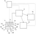
도 1을 참조하면, 본 발명은 공장 등의 산업체 또는 산업 설비에 구비된 전력을 소모하는 전력 장치 모두를 그 대상으로 할 수 있다. 이하 공장, 산업체, 산업 설비 등은 복수의 전력 장치가 배치되는 장소의 의미로 혼용되어 사용될 수 있다. 이하 전력 장치는, 전력 수요 예측의 대상으로 저항형 전열기, 히트 펌프, 스위칭 변압기, 모터, 또는 용해로 등을 포함하며, 전력을 소모하여 전력 데이터 수집이 가능한 것이면 적용가능하다.Referring to FIG. 1, the present invention can be applied to all power devices that consume power provided in industrial enterprises or industrial facilities such as factories. Hereinafter, the terms factory, industry, industrial facility, etc. may be used interchangeably to mean a place where a plurality of power devices are installed. Hereinafter, power devices include resistance-type electric heaters, heat pumps, switching transformers, motors, or melting furnaces as objects of power demand prediction, and are applicable as long as they consume power and enable power data collection.
이하 산업체의 전력 장치는 부하(L)와 동일한 의미로 사용될 수 있다. 전력 데이터는 해당 부하(L)의 전류, 전압, 전력를 포함하는 전기 관련 데이터로 특별한 언급이 없어면 혼용될 수 있다. 예로 하위 배전반(30)에 연결된 부하(L)의 실시간 전류를 측정하는 센서(S)의 전류 데이터를 각 부하(L)별로 분별하고 상위 배전반(50)의 피크 전력 관리, 부하(L) 고장 여부 파악 등에 활용할 수 있는데, 이를 위해 전압 강하를 수행할 수 있으므로, 전류, 전압, 전력 데이터 간은 혼용될 수 있다.Hereinafter, industrial power devices may be used in the same sense as load (L). Power data is electricity-related data including current, voltage, and power of the corresponding load (L) and can be used interchangeably unless otherwise specified. For example, the current data of the sensor (S) that measures the real-time current of the load (L) connected to the lower switchboard (30) is classified for each load (L), the peak power of the upper switchboard (50) is managed, and whether the load (L) is broken. It can be used for identification, etc., and for this purpose, voltage drop can be performed, so current, voltage, and power data can be used interchangeably.
데이터 수집부(110)는 부하(L)의 전력 데이터 및 매핑부(130)의 매핑 데이터를 포함하는 원시 데이터를 수집할 수 있다.The
전력 계통의 상위 계통에 해당하는 상위 배전반(50)으로부터 전력 계통의 하위 계통에 해당하는 복수의 하위 배전반(30)이 분기될 수 있다. 상위 계통 및 하위 계통은, 전력 공급자를 기준으로 전력을 공급받는 말단의 부하(L)에 걸친 전력 계통에 있어, 상류에 위치하면 상위 계통, 하류에 위치하면 하위 계통으로 하여 적용이 확장될 수 있다.A plurality of lower distribution boards 30 corresponding to lower systems of the power system may be branched from the
도 1에서는 일 실시 예로, 각 하위 배전반(30)은 개별 산업체(공장)에 대응할 수 있고, 복수의 하위 배전반(30)이 분기되는 상위 배전반(50)은 변압기가 설치된 곳을 의미할 수 있다. 즉, 제1 하위 배전반(30a)은 제1 산업체(제1 공장)를 나타내고, 제2 하위 배전반(30b)은 제2 산업체(제2 공장)를 나타내며, 제3 하위 배전반(30c)은 제3 산업체(제3 공장)를 나타낼 수 있고, 각 하위 배전반(30)에는 복수의 부하(L)가 연결될 수 있다.In FIG. 1 , as an example, each lower distribution board 30 may correspond to an individual industrial enterprise (factory), and the
수요 전력 예측에 기초해 수행되는 전압 제어는 상위 배전반(50) 또는 하위 배전반(30) 모두에서 수행가능하나, 본 발명은 상위 배전반(50)에서 수집된 전력 데이터로(111)부터 개별 부하(L)의 전력 데이터를 분별하여, 부하별 전압 또는 전력 제어를 하고자 하기에, 개별 부하(L)를 제어하는 하위 배전반(3)이 주된 전압 제어의 대상이 될 수 있다.Voltage control performed based on demand power prediction can be performed in both the
도 1에서는, 하위 배전반(30)의 일 실시 예로, 하류의 부하들(L1 ~ L6)이 하위 배전반(30)에서 모두 제어가능한 것으로 도시되어 각 부하(L1 ~ L6)마다 대응하는 센서(S)가 구비된 것을 나타낸다. 그러나, 전력 설비 구조상 소정의 하위 배전반(30)의 하류에 위치하는 전력 장치(L)들은 하위 배전반(30)에서가 아닌 개별 위치에서 전압 조정되는 경우도 포함할 수 있다.In Figure 1, as an example of the lower distribution board 30, the downstream loads (L1 to L6) are all shown as controllable from the lower distribution board 30, and a sensor (S) corresponding to each load (L1 to L6) is shown. Indicates that is provided. However, due to the power facility structure, power devices L located downstream of a certain lower distribution board 30 may have their voltage adjusted at individual locations rather than at the lower distribution board 30.
도 1에서, 데이터 수집부(110)는 모든 전력 장치(부하(L))별로 전력 데이터를 측정하는 센서(S)가 모두 구비된 제1 경우를 도시한다. 특징 추출부(310)의 특징 추출, 레이블부(330)의 레이블 부여, 특징 결합부(350)의 특징 및 레이블 재결합(재조합), 학습부(370)의 학습 방식, 또는 분류부(390)의 전력 데이터 분류 방식에 따라, 데이터 수집부(110)는 하위 배전반(30) 또는 상위 배전반(50)에만 마련되어 취합된 전력 데이터 정보를 수집하는 제2 경우를 포함할 수 있다. 상기 적어도 일부만 제1 경우 또는 제2 경우에 해당하여 제1 경우와 제2 경우가 혼합된 경우로도 확장가능하다.In FIG. 1 , the
서버(80)는 상기 제1 경우에서, 상위 배전반(50)의 계측기, 하위 배전반(30)의 계측기, 및 부하별 전력 데이터를 수집하는 복수의 센서(S1 ~ S6)와 데이터를 송수신할 수 있다.In the first case, the
서버(80)는 상기 제2 경우에서, 상위 배전반(50)의 계측기 및 하위 배전반(30)의 계측기와 데이터를 송수신할 수 있고, 하위 배전반(30)의 계측기에는 그 하류에 위치하는 부하들(L)의 전력 데이터가 취합되어 전송되고, 상위 배전반(30)의 계측기에는 그 하류에 위치하는 하위 배전반들(30)의 전력 데이터가 취합되어 전송될 수 있다.In the second case, the
데이터 수집부(110)을 제외한 나머지 구성 요소들은 서버(80)에 포함될 수 있다. 예를 들어, 상위 배전반(50) 또는 하위 배전반(30)의 전압 조정기를 제어할 수 있는 제어부(200)는 서버(80)에 위치하여 상위 계통 또는 하위 계통으로부터 전송되는 전력 데이터로부터 전력 예측부(470)의 예측에 기초해 최종적인 전압 제어 지령을 하달할 수 있다.Except for the
상위 계통 또는 하위 계통의 전압 조정기는, 주 선로의 활선 상태에서 탭을 변경해 지정된 권선 전압으로 조정할 수 있는 권선형 타입으로, OLTC(On Load Tap Changer)를 포함할 수 있다.The voltage regulator of the upper or lower system is a winding type that can be adjusted to a specified winding voltage by changing the tap in the live state of the main line, and may include an OLTC (On Load Tap Changer).
상위 계통 또는 하위 계통의 전압 조정기는, 복수의 전력반도체 소자를 포함하는 전력변환기의 기능을 하는 하이브리드 반도체형 전압 조정기일 수 있다.The voltage regulator of the upper or lower system may be a hybrid semiconductor type voltage regulator that functions as a power converter including a plurality of power semiconductor elements.
이와 같은 본 발명의 전압 조정기는, 반도체형 전기 회로를 통칭할 수 있고, 피드백 제어기일 수 있으며, 비례(Proportional), 적분(Integral), 미분(Differential) 제어기, 또는 이들의 조합을 포함할 수 있다.The voltage regulator of the present invention may refer to a semiconductor-type electric circuit, may be a feedback controller, and may include a proportional, integral, differential controller, or a combination thereof. .
따라서, 본 발명의 전압 조정기의 일 실시 예는, 3상 전력용 하이브리드 변압기일 수 있고, 반도체식 하이브리드 전압조정기로써 전력 레벨 감소 및 최적의 전력 밀도를 얻을 수 있는 구조로 구성하여 전압 제어를 할 수 있으며, 전체 전력 중 일부를 교류-직류-교류의 과정으로 변환할 수 있고, 탭 전환기를 사용하지 않고 전력변환기를 통해 전압, 전류 및 역률을 제어할 수 있다.Therefore, an embodiment of the voltage regulator of the present invention may be a three-phase power hybrid transformer, and as a semiconductor hybrid voltage regulator, voltage control can be achieved by constructing a structure that can reduce the power level and obtain optimal power density. Some of the total power can be converted into the process of alternating current-direct current-alternating current, and voltage, current, and power factor can be controlled through a power converter without using a tap changer.
반도체형 전압 조정기는, 전압 변경 횟수에 대한 수명 개념이 없고, 제어 단위가 아주 세밀해지며, 디지털신호처리장치(DSP, Digital Signal Processor)에 의해 실시간 제어 가능하기에, 상위/하위 계통의 다층 계통 제어에 적합할 수 있다.Semiconductor-type voltage regulators have no concept of lifespan regarding the number of voltage changes, have very detailed control units, and can be controlled in real time by a digital signal processor (DSP), so they can be used in multi-layer systems of upper/lower systems. May be suitable for control.
본 발명의 매핑부(130)는 각 부하(L) 및 각 부하(L)의 전력 데이터를 상호 매핑 또는 매칭하는 매핑 데이터를 생성할 수 있다. 제1 경우에서, 만일 부하별(L)로 센서(S)가 모두 구비된다면, 공장의 운영과 함께 실시간으로 생성되는 부하별(L) 전력 데이터에 각 부하(L) 또는 센서(S)가 매핑될 수 있다.The
매핑부(130)의 매핑 데이터는 레이블부(330)의 레이블 부여 또는 학습부(370)의 학습시, 전력 데이터의 분별에 이용될 수 있습니다. 즉, 레이블부(330)는 부하별 전력 데이터 간을 상호 분별하는데 이용되는 레이블(B)을 부여할 수 있고, 학습부(370)는 부하별 전력 데이터의 분별 또는 패턴 파악을 학습할 수 있다.The mapping data of the
본 발명의 목적 중 하나는, 상위 계통(상위 배전반)에서의 전력 피크가 예상시 하위 계통(하위 배전반)의 전력을 제어하고자 하는 것이고, 더 구체적으로는 하위 배전반(30)에 연결된 모든 부하(L)를 수집부터 제어까지 추적하고자 하는 것이므로, 매핑 데이터는 전력 데이터 수집으로부터 부하별 전력 제어까지 전력 데이터의 특정과 분별에 필요할 수 있다.One of the purposes of the present invention is to control the power of the lower system (lower switchboard) when a power peak in the upper system (upper switchboard) is expected, and more specifically, all loads (L) connected to the lower switchboard 30. ) from collection to control, mapping data may be necessary for specifying and discriminating power data from power data collection to load-specific power control.
본 발명의 산업체 전력 제어 장치는, 제어부(200), 특징 추출부(310), 레이블부(330), 특징 결합부(350), 학습부(370), 및 분류부(390) 중 적어도 하나를 포함할 수 있다.The industrial power control device of the present invention includes at least one of a
제어부(200)는 도 2에 도시된 산업체 전력 제어 장치에 속하는 구성 요소들의 전체 수행을 제어 또는 조정할 수 있다. 일 실시 예로, 제어부(200)는 전력 예측부(470)에 의한 전력 예측 결과를 이용해, 상위 배전반(50)에 대한 상위 계통의 전압 조정, 또는 하위 배전반(30)과 그 하위 배전반(30)에 연결된 부하들(L)에 대한 하위 계통의 전압 조정을 수행할 수 있다.The
도 3을 참조하여, 본 발명의 특징 추출 및 특징 재조합에 대해 설명한다.Referring to Figure 3, feature extraction and feature recombination of the present invention will be described.
특징 추출부(310)는 전력 데이터에 내재된 복수의 특징(F) 중 적어도 하나를 필터링할 수 있다.The
특징(F)은 부하(L)에서 수집된 전력 데이터로부터 추출가능한 고유의 특성을 의미할 수 있다. 예를 들어, 특징(F)은, 차수별 왜형률, 지난 Time frame(또는 windows)과 전압 또는 전류의 차분, 전류 파형(waveform)의 미분값이 급변하는 지점(또는 파형이 일그러지는 지점)에 대한 맵(map), 및 최소 최대 정규화(min max normalization) 등의 정규화(normalizing) 된 파형(waveform) 자체 중 적어도 하나를 포함할 수 있다.The feature (F) may mean a unique characteristic that can be extracted from power data collected from the load (L). For example, the feature (F) is the distortion rate by order, the difference between the last time frame (or windows) and voltage or current, and the point where the differential value of the current waveform changes suddenly (or the point where the waveform is distorted). It may include at least one of a map and a normalized waveform such as min max normalization.
일반적인 전력 데이터의 파형은 정현파 및 고조파가 중첩된 것이고, 왜형률은 기본파인 정현파 대비 고조파 성분의 값일 수 있다.The waveform of general power data is one in which sinusoids and harmonics overlap, and the distortion rate may be the value of the harmonic component compared to the sinusoidal wave, which is the fundamental wave.
이와 같이, 본 발명은, 기존의 푸리에 변환을 통한 주파수-진폭 등의 데이터 추출에만 기반해 전류,전력 데이터를 분석하는 것이 아니라, 주파수 해석도 본 발명의 특징(F) 중 하나가 될 수 있으며, 상기 나열된 특징(F)의 구성요소들 외에도 부하별 전력 데이터 분별에 이용가능한 것이면 특징(F)에 포함될 수 있다.As such, the present invention does not analyze current and power data based only on data extraction such as frequency-amplitude through the existing Fourier transform, but frequency analysis can also be one of the features (F) of the present invention. In addition to the components of the feature (F) listed above, any element that can be used to distinguish power data for each load may be included in the feature (F).
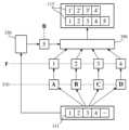
특징 추출부(310)에 입력되는 전력 데이터(111)는 상기 복수의 특징(F)들이 내재된 것이고, 특징 추출부(A,B,C,D)에 의해 각 특징들(1,2,3,4, 또는 F1,F2,F3,F4 로 표시)이 추출(필터링)될 수 있다. 제1 특징 추출부(A)에 의해 제1 특징(F1)이 추출되고, 제2 특징 추출부(B)에 의해 제2 특징(F2)이 추출되는 등이다.The
특징 결합부(350)는 추출되고 일부 가공된 특징(F)들을 재조합하여 전력 데이터를 복원할 수 있다. 추출된 특징(F)들의 가공은 특징 추출부(310)와 특징 결합부(350)의 사이에 별도의 구성요소에 의해 수행되거나, 특징 결합부(350) 자체에서 수행될 수 있다.The
특징 결합부(350)의 재조합시 레이블부(330)에 의한 레이블(B 또는 5)이 추가될 수 있다. 레이블(B 또는 5)은 재조합되는 전력 데이터(113)를 서로 분별시키고 상호 식별케하는 이름표의 기능을 할 수 있다.When the
재조합된 전력 데이터(113)는, 재조합된 특징(F)에 레이블(5)이 부착되거나, 적어도 일부의 특징(F)에 더해져 재조합된 전력 데이터(113) 간의 분별 기능을 수행할 수 있다.The recombined
레이블부(330)는 레이블(B) 부여시, 수집된 원시 데이터 중 매핑 데이터를 전송받아 활용할 수 있다.When assigning a label (B), the
특징 추출부(310)의 특징 추출 및 특징 결합부(350)의 특징 재조합은 전력 데이터를 특징 공간(feature space)에 임베딩(embedding)하여 처리하는 것일 수 있다.Feature extraction of the
도 4를 참조하면, 소정의 전력 데이터는 특징 공간(feature space)의 특징 벡터(FV, Feature Vector)로 표현될 수 있다. 각 특징(F)들은 특징 공간의 각 축을 이룰 수 있고, 특징 벡터(FV)를 각 축(F)의 성분으로 분해하는 것은 특징 추출부(310)에 의한 특징(F) 추출에 대응할 수 있다. FV-1 은 특징 벡터(FV)를 제1 특징(1, F1)으로 성분 분해한 것을 나타내고, FV-2 는 특징 벡터(FV)를 제2 특징(1, F2)으로 성분 분해한 것을 나타내는 등의 방식이다.Referring to FIG. 4, certain power data can be expressed as a feature vector (FV) in a feature space. Each feature (F) can form each axis of the feature space, and decomposing the feature vector (FV) into components of each axis (F) can correspond to feature (F) extraction by the
특징 추출부(310)의 특징(F) 추출에 대응하는 특징 벡터(FV)의 각 특징 축으로의 성분 분해는, 도 4와 같이 단순히 스칼라양의 대소로 판단되는 것에 한정되지 않으며, 차수별 왜형률, 지난 Time frame(또는 windown)과 전압 또는 전류의 차분, 전류 파형(waveform) 의 미분값이 급변하는 지점(또는 파형이 일그러지는 지점)에 대한 맵(map), 및 최소 최대 정규화(min max normalization) 등의 정규화(normalizing) 된 파형(waveform) 자체 중 적어도 하나를 포함하는 특징(F)별 스케일이나 차원을 가질 수 있다는 것을 상징적으로 나타낸다.Component decomposition into each feature axis of the feature vector (FV) corresponding to the feature (F) extraction of the
이러한 방식으로 N개의 특징(F)가 전력 데이터에 내재된 경우, 소정의 전력 데이터는 N개의 축으로 이루어진 특징 공간 상의 특징 벡터(FV)로 표현되며, N 개의 성분으로 분해된 후 가공 등의 후처리를 거쳐 특징 결합부(350)에 의해 재조합될 수 있다.In this way, when N features (F) are embedded in the power data, the given power data is expressed as a feature vector (FV) in a feature space consisting of N axes, is decomposed into N components, and then processed, etc. After processing, it can be recombined by the
특징 결합부(350)에 의한 특징(F)의 재조합은 그 목적에 따라 다양한 방식으로 수행될 수 있다. 입력되는 전력 데이터(111)의 내재된 특징별 패턴을 확인하고 분별하려는 경우 모든 특징 결합부(350)의 특징을 분해후 다시 재조합하고 레이블(B) 부여를 할 수 있다. 특징(F) 중 몇가지만 소정의 부하의 전력 데이터 분별에 필요한 경우 나머지 특징(F)들은 제외시키고 필요한 특징들만 취사선택할수도 있다.Recombination of the feature (F) by the
학습부(370)는 각 부하별(L)로 수집된 전력 데이터를 입력받아 특징 추출 및 재조합을 수행하여, 각 부하별(L) 전력 데이터의 특징들을 학습할 수 있다.The
물론, 산업체 기계들의 모든 전력 데이터를 학습하여 각 부하 개별로 정상 또는 비정상의 패턴을 예측하거나, 각 부하 개별로 전력 수요 변동을 예측하여 전압 조정을 할 수도 있다. 그러나, 모터 등과 같이 산업체 중에 특정된 기계류가 아닌 산업체 기계류 전체를 그 대상으로 하고자 하는 경우 개별 부하 전부를 추적하고 예측하는 것은 너무 많은 시간이 소비될 수 있고, 현실적으로도 모든 기계의 전류 데이터를 정확히 실시간으로 전부 측정하는 것은 힘들 수 있다.Of course, it is also possible to predict normal or abnormal patterns for each load by learning all the power data of industrial machines, or to predict power demand fluctuations for each load and adjust the voltage. However, if the target is the entire industrial machinery, rather than specific machinery such as motors, etc., tracking and predicting all individual loads may be too time-consuming, and in reality, current data from all machines must be collected accurately in real time. It can be difficult to measure everything.
학습부(370)의 학습은, 개별 부하별 전력 데이터로부터 각 패턴을 정립하는 것, 취합된 전체 전력 데이터로부터 부하별 전력 데이터를 분별하는 것, 취합된 전체 전력 데이터로부터 부하별 이상 패턴을 감지하는 것 등을 포함할 수 있다.The learning of the
이러한 특징 추출부(310), 레이블부(335) 및 특징 결합부(350)에 의한 특징 추출 및 특징 재조합의 과정은 수없이 많은 전력 데이터에 대해 반복적으로 수행될 수 있다. 이러한 반복적인 학습에 이용되는 전력 데이터는 계측기(센서,S)로부터 고속으로 방대한 데이터가 제공되는 것이 바람직할 수 있다.The process of feature extraction and feature recombination by the
일 실시 예로, 계측기는 20 hz 내지 50 khz 의 해상도를 가지는 홀 효과(Hall effect) 전류 센서일 수 있고, 600 hz 내지 1200 hz 의 샘플링 레이트로 전류값에 대한 원시 데이터를 취득할 수 있다.In one embodiment, the instrument may be a Hall effect current sensor with a resolution of 20 Hz to 50 khz, and may acquire raw data about current values at a sampling rate of 600 Hz to 1200 Hz.
학습부(370)는, 전력 데이터 패턴을 초기에 개별 부하별로 패턴 기억용으로 입력받아 학습하고, 취합된 전체 전력 데이터로부터 각 부하별 전력 데이터를 분별하는 학습을 할 수 있다. 이때, 분류부(390)는 학습부(370)에 의한 학습 결과에 기초해 실시간 측정되는 전력 데이터들의 각 성분들이 어느 부하로 분별되는지를 계속적으로 기록하고 저장 분별할 수 있다. 즉, 분류부(390)는 학습부(370)에 의한 학습 결과에 기초해 실시간 측정되는 전체 전력 데이터를 각 부하별 전력 데이터로 분별할 수 있다.The
이러한 학습부(370) 및 분류부(390)에 의해 분별된 전력 데이터들은, 부하별정상 동작 여부를 판단하는데 이용될 수 있고, 취합되는 지점(상위 배전반(50) 또는 하위 배전반(30))의 피크 전력 관리 등 전압 제어의 필요가 있는 경우 부하별 분석된 전력 데이터를 이용해, 부하별 가장 최적의 전압 제어 방법을 찾는데 이용될 수 있다.The power data classified by the
본 발명의 산업체 전력 제어 장치는 패턴 파악부(410), CVRf 추정부(430), 스케쥴링부(450), 및 전력 예측부(470) 중 적어도 하나를 포함할 수 있다.The industrial power control device of the present invention may include at least one of a
패턴 파악부(410)는, 학습부(370)에 의한 학습 및 분류부(390)에 의한 분류에 기반해, 개별 부하별 정상 동작 패턴 또는 복수의 부하가 포함된 전체 산업체 설비의 정상 패턴을 파악할 수 있고, 개별 부하별(L) 정상 동작 여부 또는 복수의 부하가 포함된 전체 산업체 설비의 정상 동작 여부를 판단할 수 있다.The
패턴 파악부(410)는 취합된 전체 전력 데이터로부터 분류된 개별 부하별 전력 데이터를 실시간으로 계속 추적/분석하여 어느 부하가 비정상 작동하고 있는지를 신속히 판정할 수 있고, 오작동 패턴이 반복적이라면 오작동 발생전 발생 시점을 예측하여 미리 조치를 취하는 것이 가능할 수 있다.The
또한, 산업체 설비에는 부하(L)의 종류에 따라 저항성 부하, 인버터 부하, 냉난방기 부하, 전동기 부하 등이 포함될 수 있는데, 패턴 파악부(410)는 부하의 종류에 따라 전력 데이터의 패턴이 분별될 수 있다. 취합된 전체 전력 데이터의 비정상적인 패턴 발생시 어떤 부하의 종류에서 발생하는 패턴인지를 먼저 파악한 후, 각 부하의 종류안에 포함된 개별 부하의 데이터를 살펴봄으로써, 신속히 문제되는 부하의 종류를 파악할 수 있고, 부하 종류별 전력 데이터의 패턴에 대한 정보는 관리자의 관리 측면에서도 유용할 수 있다.In addition, industrial facilities may include resistive loads, inverter loads, air conditioner loads, electric motor loads, etc. depending on the type of load (L), and the
학습부(370)의 학습에서도 개별 부하별 전력 데이터를 전부 예측하는 것이 어렵고 모든 부하에 계측기(S)를 전부 마련하는것은 현실적으로도 쉽지 않기에, 주된 부하 또는 적어도 일부의 부하의 전력 데이터의 패턴 파악을 위한 입력 외에는 전체 전력 데이터로부터 학습하는 것이 학습 시간과 학습량을 줄일 수 있는 것과 마찬가지로, 패턴 파악부(410)도 부하별 전력 데이터를 전부 추적하여 정상 패턴과 오작동 패턴을 분별할 수도 있지만 취합된 전체 전력 데이터의 전체 패턴을 추적하여 평소와 다른 패턴을 보이면, 그 패턴 동작이 어느 부하의 이상으로부터 기인하는 지를 판별함으로써 오작동 패턴 원인 파악에 걸리는 시간을 단축할 수 있다.Even in the learning of the
상위 계통 변전소에서 공급 전압 제어를 통해 전력 감축을 진행하고자 할 때, 공급자가 약정한 전압 변동률 범위를 지키면서, 제어 가능한 전압의 경우의 수는 제한적이며, 그로 인한 피크 제어 커버리지는 작을 수 있다.When attempting to reduce power through supply voltage control at the upper system substation, the number of voltage cases that can be controlled while maintaining the voltage change rate range agreed upon by the supplier is limited, and the resulting peak control coverage may be small.
특히, 예를 들어 0.5% ~ 12.5% 단위로 제어되는 기존의 탭 전환 방식의 전압 조정 방식으로는 전력 예측에 따른 미세한 전압 조정이 힘들어, 공급 전압 품질면에서 수용가 측에서 관측되는 가시적인 변화가 발생될 수 있다.In particular, it is difficult to finely adjust voltage according to power prediction using the existing tap switching voltage adjustment method, which is controlled in increments of 0.5% to 12.5%, resulting in visible changes observed by consumers in supply voltage quality. It can be.
따라서, 본 발명은 반도체형 전압 조정기를 채택가능하며, 예로 0.1 % 단위로 부하별 전압 조정기를 개별 제어할 수 있다. 이러한 미세한 전압 제어는 모든 부하별 전력 데이터 분석 및 스케쥴링과 연계되어 상위 계통 전체 전력 데이터 및 하위 계통 부하별 전력의 품질 하락없는 전력 제어로 이어질 수 있다.Therefore, the present invention can adopt a semiconductor-type voltage regulator, and for example, the voltage regulator for each load can be individually controlled in 0.1% units. This fine voltage control can be linked to the analysis and scheduling of power data for each load, leading to power control without deterioration in the quality of power data for the entire upper system and for each load in the lower system.
CVRf 추정부(430)는 분류부(390)에 의해 분류된 개별 부하별(L) 전력 데이터에 기초해, 부하별 보존전압강하계수(CVRf, CVR factor, Conservation Voltage Reduction factor)를 실시간으로 추정 또는 추적할 수 있다.The
보존전압강하계수(CVRf)는 전압 변동률에 대한 전력 변동률일 수 있다. 예를 들어, 전압이 1% 내려갈 때, 전력이 2% 내려가면 CVRf는 2일 수 있다. 보존전압강하계수(CVRf)에 의해, 실제 절감된 전력 절감량을 추정하는데 이용될 수 있다.The conservation voltage drop coefficient (CVRf) may be the power change rate relative to the voltage change rate. For example, when the voltage goes down by 1% and the power goes down by 2%, CVRf may be 2. The conservation voltage drop coefficient (CVRf) can be used to estimate the actual amount of power saved.
CVRf 추정부(430)는 각 전압 조정기의 부하별 CVRf 예측하거나, CVRf 가중평균치를 실시간 추정할 수 있다.The
CVRf 추정부(430)는, 학습부(370) 학습 및 분류부(390)의 분류에 따른 부하별 전력 데이터에 기초해, 보존전압강하계수(CVRf), 그 보존전압강하계수에 대한 가중 평균으로부터 전력 데이터가 취합되는 상류의 전체 보존전압강하계수를 예측할 수 있다.The
전력 예측부(470)는, 하위 계통의 하위 배전반(30)이 복수이고, 그 상류의 상위 계통의 상위 배전반(50)에 복수의 하위 배전반(30)이 분기된 경우, 하위 계통의 부하별 전력 예측값을 취합하여 상류의 하위 계통 또는 그 상류의 상위 계통의 총 미래 전력을 예측할 수 있다.The
스케쥴링부(450)는, 하위 계통의 부하별 전력 데이터로부터 전력 예측부(470)의 상위 계통의 피크 전력 발생 등의 문제 발생이 예측되는 경우, 예측된 상위 계통의 전력이 계획 범위 상한선을 초과할 것으로 예측되면, 하위 계통의 부하별 전력 제어를 위한 알고리즘을 수행할 수 있다.If a problem such as peak power generation in the upper system of the
즉, 스케쥴링부(450)는, CVRf 추정부(430)의 예측에 기초해, 상위 배전반(50) 또는 하위 배전반(30)의 피크 전력 제어시, 어떤 하위 계통의 어떤 부하에 대해 전압 조정기를 얼마만큼 전압 제어함에 따른 상위 계통의 피크 전력 제어 정도를 예측할 수 있다.That is, based on the prediction of the
스케쥴링부(450)는, CVRf 추정부(430)로부터 산출된 부하별 보존전압강하계수(CVRf), 그 보존전압강하계수에 대한 가중 평균으로부터 전력 데이터가 취합되는 상류의 전체 보존전압강하계수를 고려하여, 각 부하에서 CVRf이 큰 순서대로 소정의 전압값을 조정량을 더하며, 상위 계통에서 요구되는 피크 제어량이 달성될 때까지 조정되어야할 하위 계통의 전압 조정기의 전압 조정 범위를 넓혀 갈 수 있다.The
일 예로, 전압 조정기가 반도체형인 경우, 상기 소정의 전압값은 0.1% 일 수 있고, 0.1% 씩 미세한 조정이 가능할 수 있다.For example, if the voltage regulator is a semiconductor type, the predetermined voltage value may be 0.1%, and fine adjustment by 0.1% may be possible.
다른 예로, OLTC 방식의 권선형인 경우, 전압 조정 폭이 적은 전압 조정기부터 순차적으로 제어될 수 있고, 목표 피크 제어치가 달성되면 전압 제어가 중단될 수 있다. 이 경우 전압 조정기의 1조정 주기당 전압 조정기 한대씩 적은 전압 조정기부터 제어되며 원하는 전압에 달성하여 예측된 피크 시점에 전력 계획의 상한선을 넘지 않을 수 있다.As another example, in the case of the OLTC type winding type, voltage regulators with a small voltage adjustment range can be controlled sequentially, and voltage control can be stopped when the target peak control value is achieved. In this case, one voltage regulator per regulation cycle of the voltage regulator is controlled starting from the smallest voltage regulator, and the desired voltage can be achieved without exceeding the upper limit of the power plan at the predicted peak time.
전력 예측부(470)에 의한 전력 예측과 실제 발생한 전력값과 비교해, 전력 예측이 기설정된 신뢰도를 만족한다면, 스케쥴링부(450)에 의한 스케쥴링 알고리즘을 유지할 수 있다.If the power prediction by the
전력 예측부(470)에 의한 전력 예측과 실제 발생한 전력값과 비교해, 전력 예측이 기설정된 신뢰도를 벗어난다면, 스케쥴링부(450)는 신뢰도 회복을 위해 스케쥴을 수정, 취소, 또는 강화할 수 있다. 이러한 스케쥴의 조정은 부하별로 이루어질 수 있다.If the power prediction by the
이러한 스케쥴링부(450)의 전력 예측값과 실제 전력값의 차이에 대한 피드백 과정은 다른 구성 요소들에도 적용될 수 있다.This feedback process for the difference between the power prediction value of the
예를 들어, 스케쥴링부(450)의 피드백으로 인한 스케쥴링 변경에도 불구하고, 신뢰도 만족이 안된다면, CVRf 추정부(430)는 CVRf 가중치를 조정할 수 있다.For example, if reliability is not satisfied despite a scheduling change due to feedback from the
또한, 패턴 파악부(410)를 포함하는 다른 구성요소들도 발생한 피크 전력에서의 예측값과의 차이를 반영해 계속적으로 자신의 판단 결과를 업데이트할 수 있다.Additionally, other components including the
CVRf 추정부(430)의 CVRf 은, 전력 예측부(470)에 의한 피크 전력 발생 등의 문제 발생이 예측되는 경우, 스케쥴링부(450)에 의한 스케쥴링 설정 또는 제어부(200)에 의한 전압 제어 등에 이용될 수 있다.The CVRf of the
기존의 CVR Factor 추정 방법은 수용가(부하 집단) 외적인 요인으로 일시적인 큰 전압 변동이 발생했을 때 한정적으로 측정하는 것이 대부분이다.Most existing CVR Factor estimation methods are limited to measurements when large temporary voltage fluctuations occur due to factors external to the customer (load group).
상위 계통 변전소에서 모든 수용가의 CVR Factor를 실시간으로 파악할 수 없다면, 전압 강하에 따른 피크 전력 감축 효과를 예측 및 평가할 수 없으며, 전압 변동 후 관찰된 전력 변동만으로 CVR Factor를 추정하는 경우, 이것을 관측한 후 후행적으로 룰베이스 기법에 따라 전압 제어를 수행 하기 때문에, 성공적인 피크 제어에 어려움이 따를 수 있다.If the CVR Factor of all customers cannot be identified in real time at the upper system substation, the peak power reduction effect due to voltage drop cannot be predicted and evaluated, and if the CVR Factor is estimated only with the power change observed after the voltage change, after observing this Since voltage control is performed later according to the rule base technique, there may be difficulties in successful peak control.
따라서, 본 발명의 실시간 CVRf 추정 방법은 하위 계통기에 연결된 각 부하들의 CVR Factor의 가중평균을 실시간으로 추정/예측할 수 있다.Therefore, the real-time CVRf estimation method of the present invention can estimate/predict the weighted average of the CVR Factor of each load connected to the lower system in real time.
본 발명의 실시간 CVRf 추정이 필요한 이유는, 상위 배전반(50)에서 피크 전력 제어를 위해 수용가(부하)와 전력 공급 계약을 체결할 때, 정확한 CVR Factor 를 실시간으로 제공 받기 위한 설비 부착이나 사용 설비 내역을 받는 일은 현실적으로 불가능하기 때문일 수 있다.The reason why real-time CVRf estimation of the present invention is necessary is because when entering into a power supply contract with a consumer (load) for peak power control at the
도 5 내지 도 8, 및 상기 산업체 전력 제어 장치에 대한 내용을 참조하여, 본 발명의 산업체 전력 제어 방법에 대해 설명한다.With reference to FIGS. 5 to 8 and the contents of the industrial power control device, the industrial power control method of the present invention will be described.
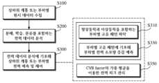
본 발명의 산업체 전력 제어 방법은, 원시 데이터 수집 단계(S100), 전력 데이터 분석 단계(S200) 및 전력 예측 및 제어 단계(S300) 중 적어도 하나를 포함할 수 있다.The industrial power control method of the present invention may include at least one of a raw data collection step (S100), a power data analysis step (S200), and a power prediction and control step (S300).
원시 데이터 수집 단계(S100)는 전력 데이터 수집 단계(S110) 또는 매핑 데이터 생성 단계(S130)를 포함할 수 있다.The raw data collection step (S100) may include a power data collection step (S110) or a mapping data generation step (S130).
전력 데이터 수집 단계(S110)는 원시 데이터를 수집하는 것일 수 있고, 원시 데이터는 하위 계통 단의 적어도 일부의 부하별 전력 데이터, 또는 하위 계통의 상류에 위치하는 상류 계통 단의 취합된 전력 데이터를 포함할 수 있다.The power data collection step (S110) may be collecting raw data, and the raw data includes power data for each load of at least a portion of the sub-system, or collected power data of the upstream system located upstream of the sub-system. can do.
하위 배전반(30)에 구비된 계측기(센서,S)는 부하별 전력 데이터를 설정된 단위 시간에 따라 측정할 수 있다.A measuring instrument (sensor, S) provided in the lower distribution panel 30 can measure power data for each load according to a set unit time.
매핑 데이터 생성 단계(S130)는 매핑 데이터를 수집하는 것일 수 있으며, 매핑 데이터는 매핑부(130)에 의해 각 부하(L)와 그 부하(L)의 전력 데이터, 또는 각 부하(L)와 그 부하(L)의 계측기(S)를 상호 매핑/매칭하는 것일 수 있다.The mapping data generation step (S130) may be collecting mapping data, and the mapping data may be divided into each load (L) and the power data of the load (L), or each load (L) and the power data of the load (L) by the
전력 데이터 분석 단계(S200)는 상기 원시 데이터 수집 단계(S100)의 전력 데이터를 매핑 데이터, 특징(F), 레이블(B), 재조합 등을 이용해 분해, 학습, 분류할 수 있다.The power data analysis step (S200) may decompose, learn, and classify the power data of the raw data collection step (S100) using mapping data, features (F), labels (B), recombination, etc.
전력 데이터 분석 단계(S200)는, 입력되는 전력 데이터(111)에 대해 특징 추출부(310)에 의한 특징(F)을 추출하는 특징 추출 단계(S210), 재조합 단계(S250)의 재조합시 레이블부(330)에 의해 레이블(B,5)을 부여하는 레이블 부여 단계(S230), 특징 추출 단계(S210)의 특징(F) 및 레이블 부여 단계(S230)의 레이블(B)을 조합하여 재조합된 전력 데이터(113)을 생성하는 재조합 단계(S250), 특징 추출 단계(S210), 레이블 부여 단계(S230) 및 재조합 단계(S250)를 통해 분류되거나 제공받은 부하별 전력 데이터의 특징 벡터를 학습하는 학습 단계(S270), 및 학습부(370)에 의한 학습 단계(S270)의 학습에 기초해 전체 전력 데이터를 부하별 전력 데이터로 분류하는 분류 단계(S290) 중 적어도 하나를 포함할 수 있다.The power data analysis step (S200) includes the feature extraction step (S210) of extracting the feature (F) by the
전력 예측 및 제어 단계(S300)는 고유 패턴 파악 단계(S310), 전력 증감 예측 단계(S330), 및 전력 피크 관리 단계(S350) 중 적어도 하나를 포함할 수 있다.The power prediction and control step (S300) may include at least one of a unique pattern identification step (S310), a power increase/decrease prediction step (S330), and a power peak management step (S350).
고유 패턴 파악 단계(S310)는 부하별 정상 동작과 이상 동작 간의 부하별 고유한 전력 데이터의 패턴을 분별하는 것, 또는 취합된 전체 전력 데이터의 정상 동작과 이상 동작 간의 패턴을 분별하여 그 패턴이 어떤 부하 또는 어떤 부하 종류의 이상 동작으로부터 기인한지 고유의 패턴을 분별하는 것을 포함할 수 있다.The unique pattern identification step (S310) is to discern the pattern of unique power data for each load between normal operation and abnormal operation for each load, or to discern the pattern between normal operation and abnormal operation of the entire collected power data to determine what the pattern is. This may include discerning unique patterns that result from abnormal behavior of the load or type of load.
전력 증감 예측 단계(S330)는 전력 예측부(470)에 의해 수행될 수 있다. 전력 예측부(470)는, 전력 데이터 분석 단계(S200)의 부하별 전력 데이터 분석에 기초해, 취합되는 단(50,30)에서의 전체 전력 데이터의 피크 전력 발생을 예측할 수 있다. 개념상 전력 증감 예측 단계(S330)는 고유 패턴 파악 단계(S310)를 포함할 수 있다.The power increase/decrease prediction step (S330) may be performed by the
고유 패턴 파악 단계(S310) 또는 전력 증감 예측 단계(S330)에 의해, 피크 전력 발생 등의 전압 제어가 필요한 상황의 발생이 예측되면, 제어부(200)는 스케쥴링부(450)의 스케쥴링에 따른 전압 제어 지령을 전압 조정기에 하달할 수 있다.If the occurrence of a situation requiring voltage control, such as peak power generation, is predicted through the unique pattern identification step (S310) or the power increase/decrease prediction step (S330), the
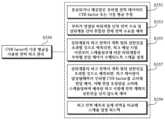
따라서, 전력 피크 관리 단계(S350)는, CVRf 추정부(430)가 분류되거나 제공받은 부하별 전력 데이터의 보존전압강하계수(CVRf) 또는 그 CVRf의 가중 평균을 추정하는 CVRf 추정 단계(S351), 전력 예측부(470)에 의해 부하가 연결된 하위 계통 단의 전력 수요 및 상위 계통 단의 취합된 전체 전력 수요를 예측하는 전력 수요 예측 단계(S353), 스케쥴링 단계(S355), 부하별 전압 제어 단계(S357), 및 피크 전력 예측과 실제 전력을 상호 비교하는 피드백 단계(S359) 중 적어도 하나를 포함할 수 있다.Accordingly, the power peak management step (S350) includes a CVRf estimation step (S351) in which the
스케쥴링 단계(S355)에서, 스케쥴링부(450)는 상위계통의 피크 전력이 계획 범위 상한선을 초과할 것으로 예측되면, 피크 예상 시점 이전부터 하위 계통 단의 부하별 전압 제어가 수행되도록 스케쥴을 설정할 수 있다.In the scheduling step (S355), if the peak power of the upper system is predicted to exceed the upper limit of the planning range, the
부하별 전압 제어 단계(S357)에서, 제어부(200)는 상위 계통의 피크 전력이 계획 범위 상한선을 초과할 것으로 예측되면, 피크 제어량이 달성될 때까지 부하별 보존전압강하계수(CVRf)를 고려해 부하별 전압 제어를 수행할 수 있다. 이때, 제어부(200)는 시간별 전압 조정량을 고려해 스케쥴링하며 예측된 피크 시점에 전력 계획 상한선을 초과치 않도록 전압을 제어할 수 있다.In the load-specific voltage control step (S357), if the peak power of the upper system is predicted to exceed the upper limit of the planning range, the
30... 하위 배전반
30a... 제1 하위 배전반
30b... 제2 하위 배전반
30c... 제3 하위 배전반
50... 상위 배전반
80... 서버
110... 데이터 수집부
111... 입력되는 전력 데이터
113... 재조합된 전력 데이터
130... 매핑부
200... 제어부
310... 특징 추출부
330... 레이블부
350... 특징 결합부
370... 학습부
390... 분류부
410... 패턴 파악부
430... CVRf 추정부
450... 스케쥴링부
470... 전력 예측부
B... 레이블
L... 부하
S... 센서(계측기)
F... 특징
FV... 특징 벡터
FV-1,2,3,4,5,6... 특징 벡터 성분
S100... 원시 데이터 수집 단계
S110... 전력 데이터 수집 단계
S130... 매핑 데이터 생성 단계
S200... 전력 데이터 분석 단계
S210... 특징 추출 단계
S230... 레이블 부여 단계
S250... 재조합 단계
S270... 학습 단계
S290... 분류 단계
S300... 전력 예측 및 제어 단계
S310... 고유 패턴 파악 단계
S330... 전력 증감 예측 단계
S350... 전력 피크 관리 단계
S351... CVRf 추정 단계
S353... 전력 수요 예측 단계
S355... 스케쥴링 단계
S357... 부하별 전압 제어 단계
S359... 피드백 단계30... Sub-distribution board
30a... 1st sub-distribution board
30b... 2nd sub-distribution board
30c... 3rd sub-distribution board
50... Upper switchboard
80...server
110... Data collection department
111... Incoming power data
113... Recombined power data
130... Mapping unit
200... Control unit
310... Feature extraction unit
330... Label section
350... Features Joint
370... Learning Department
390... Classification department
410... Pattern recognition unit
430... CVRf estimation unit
450... Scheduling department
470... power prediction unit
B...label
L... load
S... sensor (instrument)
F... Features
FV...feature vector
FV-1,2,3,4,5,6... Feature vector components
S100... Raw data collection phase
S110... Power data collection phase
S130... Mapping data creation step
S200... power data analysis step
S210... Feature extraction step
S230... Label assignment step
S250... recombination step
S270... learning phase
S290... Sorting step
S300... power prediction and control phase
S310... Unique pattern identification step
S330... Power increase/decrease prediction step
S350... Power peak management phase
S351... CVRf estimation step
S353... Power demand forecasting step
S355... Scheduling step
S357... Load-specific voltage control steps
S359... Feedback phase
Claims (13)
Translated fromKorean상기 원시 데이터 수집 단계의 전력 데이터를 분석하는 전력 데이터 분석 단계; 및
전력 예측부에 의해 미래의 전력이 예측되고, 제어부에 의해 전압 제어 지령이 하달되는 전력 예측 및 제어 단계; 를 포함하고,
상기 전력 예측 및 제어 단계에 포함되는 전력 피크 관리 단계는 CVRf 추정부에 의한 하위 배전반 또는 부하별 전력 데이터의 보존전압강하계수(CVRf) 또는 그 CVRf의 가중 평균을 추정하는 CVRf 추정 단계, 및 상기 CVRf 추정부의 CVRf 예측에 기초해, 피크 전력 제어시 상위 배전반의 피크 전력 제어 정도를 예측하는 전력 예측 및 제어 단계스케쥴이 스케쥴링부에 의해 설정되는 스케쥴링 단계를 포함하며,
상기 CVRf 추정부에 의한 하위 배전반별 또는 그 하위 배전반에 연결된 부하별 보존전압강하계수(CVRf, CVR factor, Conservation Voltage Reduction factor)나 그 CVRf의 가중 평균에 대한 추정은 실시간으로 이루어지고,
상위 배전반의 피크 전력이 계획 범위 상한선을 초과할 것으로 예측되면, 상기 제어부는 피크 제어량이 달성될 때까지 하위 배전반 또는 부하별 전압 제어를 결정하고,
상기 스케쥴링부는 상기 CVRf 추정 단계에서 산출된 상기 하위 배전반 또는 부하의 보존전압강하계수(CVRf)가 큰 순서대로 소정의 전압 조정량을 더하며, 전압 조정폭이 적은 상기 하위 배전반 또는 부하부터 순차적으로 제어함으로써, 전압 조정의 대상되는 하위 배전반 또는 부하의 범위를 넓혀가며 상위 배전반에서 요구되는 피크 제어량이 달성되도록 상기 스케쥴을 설정하며,
상기 전력 예측 및 제어 단계는 피크 전력 예측과 실제 전력을 상호 비교하는 피드백 단계를 포함하고,
상기 피드백 단계에서,
상기 스케쥴링부는, 상기 전력 예측부에 의한 전력 예측과 실제 발생한 전력값을 비교해, 전력 예측이 기설정된 신뢰도를 만족한다면, 스케쥴링 알고리즘을 유지하고, 전력 예측이 기설정된 신뢰도를 벗어난다면, 신뢰도 회복을 위해 스케쥴을 변경하며, 여기서 스케쥴 변경은 하위 배전반별 또는 부하별로 이루어지고,
상기 CVRf 추정부는, 상기 스케쥴링부의 피드백으로 인한 스케쥴링 변경에도 불구하고 신뢰도 만족이 안된다면, CVRf 가중치를 조정하는 산업체 전력 제어 방법.
A raw data collection step in which raw data including power data is collected by a data collection unit from an upper system including an upper switchboard of the power system, and a lower system including lower switchboards or loads branching from the upper switchboard;
A power data analysis step of analyzing the power data of the raw data collection step; and
A power prediction and control step in which future power is predicted by a power prediction unit and a voltage control command is issued by a control unit; Including,
The power peak management step included in the power prediction and control step includes a CVRf estimation step of estimating the conservation voltage drop coefficient (CVRf) of the power data for each sub-distribution panel or load by the CVRf estimation unit or the weighted average of the CVRf, and the CVRf Based on the CVRf prediction of the estimation unit, a power prediction and control step schedule for predicting the peak power control degree of the upper switchboard during peak power control is set by the scheduling unit, including a scheduling step,
Estimation of the conservation voltage reduction factor (CVRf, CVR factor, Conservation Voltage Reduction factor) or the weighted average of the CVRf for each sub-distribution panel or load connected to the sub-distribution panel by the CVRf estimator is performed in real time,
If the peak power of the upper distribution panel is predicted to exceed the upper limit of the planning range, the control unit determines voltage control for each lower distribution panel or load until the peak control amount is achieved,
The scheduling unit adds a predetermined voltage adjustment amount in the order of the greater conservation voltage drop coefficient (CVRf) of the lower distribution panel or load calculated in the CVRf estimation step, and sequentially controls the lower distribution panel or load starting from the lower voltage adjustment range. , the schedule is set to achieve the peak control amount required in the upper switchboard by expanding the range of the lower switchboard or load subject to voltage adjustment,
The power prediction and control step includes a feedback step for comparing peak power prediction and actual power,
In the feedback step,
The scheduling unit compares the power prediction by the power prediction unit with the actual generated power value, maintains the scheduling algorithm if the power prediction satisfies the preset reliability, and restores reliability if the power prediction deviates from the preset reliability. Change the schedule, where the schedule change is made by sub-distribution panel or load,
An industrial power control method in which the CVRf estimator adjusts the CVRf weight if reliability is not satisfied despite a scheduling change due to feedback from the scheduling unit.
상기 전력 피크 관리 단계는 상기 전력 예측부에 의해 부하가 연결된 하위 계통 단의 전력 수요 및 상위 계통 단의 취합된 전체 전력 수요를 예측하는 전력 수요 예측 단계를 포함하는 산업체 전력 제어 방법.
According to claim 1,
The power peak management step includes a power demand prediction step of predicting the power demand of the lower system stage to which the load is connected and the total power demand of the upper system stage by the power prediction unit.
상기 전력 예측 및 제어 단계는 고유 패턴 파악 단계를 포함하고,
상기 고유 패턴 파악 단계는, 부하별 정상 동작과 이상 동작 간의 부하별 고유한 전력 데이터의 패턴을 분별하거나, 취합된 전체 전력 데이터의 정상 동작과 이상 동작 간의 패턴을 분별하여 그 패턴이 어떤 부하 또는 어떤 부하 종류의 이상 동작으로부터 기인한지 고유의 패턴을 분별하는 것을 포함하는 산업체 전력 제어 방법.
According to claim 1,
The power prediction and control step includes a unique pattern identification step,
In the step of identifying the unique pattern, the pattern of the unique power data for each load is discerned between normal operation and abnormal operation for each load, or the pattern between normal operation and abnormal operation of the entire collected power data is discerned to determine which load or which load or which pattern the pattern is. An industrial power control method that includes discerning unique patterns resulting from abnormal operation of a load type.
상기 원시 데이터 수집 단계는 전력 데이터 수집 단계 및 매핑 데이터 생성 단계를 포함하고,
상기 전력 데이터 수집 단계에서, 원시 데이터는 하위 계통 단의 적어도 일부의 부하별 전력 데이터, 또는 하위 계통의 상류에 위치하는 상류 계통 단의 취합된 전력 데이터를 포함하며,
상기 매핑 데이터 생성 단계는 매핑 데이터를 수집하는 것이고,
상기 매핑 데이터는 매핑부에 의해 각 부하와 그 부하의 전력 데이터를 상호 매칭하는 것인 산업체 전력 제어 방법.
According to claim 1,
The raw data collection step includes a power data collection step and a mapping data generation step,
In the power data collection step, the raw data includes power data for each load of at least some of the sub-system stages, or collected power data of the upstream system stage located upstream of the sub-system,
The mapping data generation step is to collect mapping data,
The mapping data is an industrial power control method in which each load and the power data of the load are matched with each other by a mapping unit.
상기 전력 데이터 분석 단계는,
입력되는 전력 데이터에 대해 특징 추출부에 의한 특징을 추출하는 특징 추출 단계;
상기 특징 추출 단계의 특징 및 레이블 부여 단계의 레이블을 조합하여 특징 결합부에 의한 재조합된 전력 데이터을 생성하는 재조합 단계;
상기 재조합 단계의 재조합시, 레이블부에 의해 레이블을 부여하는 레이블 부여 단계; 를 포함하는 산업체 전력 제어 방법.
According to claim 1,
The power data analysis step is,
A feature extraction step of extracting features from the input power data by a feature extraction unit;
A recombination step of combining the features of the feature extraction step and the label of the label assignment step to generate recombined power data by a feature combination unit;
A label granting step of assigning a label by a label unit during recombination in the recombination step; Industrial power control method including.
상기 특징 추출부에 의해 추출되는 특징은, 차수별 왜형률, 시간별 전압 또는 전류의 차분, 전류 파형(waveform)의 미분값이 급변하는 지점에 대한 맵(map), 및 정규화(normalizing) 된 파형(waveform) 자체 중 적어도 하나를 포함하는 산업체 전력 제어 방법.
According to claim 10,
The features extracted by the feature extractor include distortion rate by order, difference in voltage or current by time, map of the point where the differential value of the current waveform changes suddenly, and normalized waveform. ) Industrial power control method comprising at least one of its own.
상기 특징 추출부의 특징 추출 및 특징 결합부의 특징 재조합은 전력 데이터를 특징 공간(feature space)에 임베딩(embedding)하여 처리하는 것에 대응하는 산업체 전력 제어 방법.
According to claim 10,
An industrial power control method in which the feature extraction of the feature extraction unit and the feature recombination of the feature combining unit correspond to processing power data by embedding it in a feature space.
상기 특징 추출 단계, 레이블 부여 단계 및 재조합 단계를 통해 분류되거나 제공받은 부하별 전력 데이터의 특징 벡터를 학습부에 의해 학습하는 학습 단계, 및 상기 학습 단계의 학습에 기초해 전체 전력 데이터를 부하별 전력 데이터로 분류하는 분류 단계 중 적어도 하나를 포함하는 산업체 전력 제어 방법.
According to claim 10,
A learning step in which feature vectors of power data for each load classified or provided through the feature extraction step, labeling step, and recombination step are learned by a learning unit, and based on the learning in the learning step, the entire power data is converted to power for each load. An industrial power control method comprising at least one classification step of classifying data.
Priority Applications (1)
| Application Number | Priority Date | Filing Date | Title |
|---|---|---|---|
| KR1020230037060AKR102689674B1 (en) | 2023-03-22 | 2023-03-22 | Industrial power control method for managing power peaks in the upper branch |
Applications Claiming Priority (1)
| Application Number | Priority Date | Filing Date | Title |
|---|---|---|---|
| KR1020230037060AKR102689674B1 (en) | 2023-03-22 | 2023-03-22 | Industrial power control method for managing power peaks in the upper branch |
Publications (1)
| Publication Number | Publication Date |
|---|---|
| KR102689674B1true KR102689674B1 (en) | 2024-07-30 |
Family
ID=92145294
Family Applications (1)
| Application Number | Title | Priority Date | Filing Date |
|---|---|---|---|
| KR1020230037060AActiveKR102689674B1 (en) | 2023-03-22 | 2023-03-22 | Industrial power control method for managing power peaks in the upper branch |
Country Status (1)
| Country | Link |
|---|---|
| KR (1) | KR102689674B1 (en) |
Citations (4)
| Publication number | Priority date | Publication date | Assignee | Title |
|---|---|---|---|---|
| KR20100018444A (en)* | 2008-08-06 | 2010-02-17 | 중앙대학교 산학협력단 | Apparatus and method for real-time intelligent and autonomous load management |
| KR101836439B1 (en)* | 2017-09-01 | 2018-03-09 | 주식회사 텔다 | System for predicting charging and discharging algorithm of energy storage system installed power consumer |
| JP2020201867A (en)* | 2019-06-13 | 2020-12-17 | 株式会社エナリス | Power management system, power management method and power management program |
| KR102496049B1 (en)* | 2021-12-17 | 2023-02-07 | 주식회사 크로커스 | Voltage control device for conservation voltage reduction through voltage optimization control based on load prediction model corresponding to upper grid voltage regulation |
- 2023
- 2023-03-22KRKR1020230037060Apatent/KR102689674B1/enactiveActive
Patent Citations (4)
| Publication number | Priority date | Publication date | Assignee | Title |
|---|---|---|---|---|
| KR20100018444A (en)* | 2008-08-06 | 2010-02-17 | 중앙대학교 산학협력단 | Apparatus and method for real-time intelligent and autonomous load management |
| KR101836439B1 (en)* | 2017-09-01 | 2018-03-09 | 주식회사 텔다 | System for predicting charging and discharging algorithm of energy storage system installed power consumer |
| JP2020201867A (en)* | 2019-06-13 | 2020-12-17 | 株式会社エナリス | Power management system, power management method and power management program |
| KR102496049B1 (en)* | 2021-12-17 | 2023-02-07 | 주식회사 크로커스 | Voltage control device for conservation voltage reduction through voltage optimization control based on load prediction model corresponding to upper grid voltage regulation |
Similar Documents
| Publication | Publication Date | Title |
|---|---|---|
| JP6965882B2 (en) | Maintenance planning equipment, methods and programs | |
| Wang et al. | Time-varying stochastic assessment of conservation voltage reduction based on load modeling | |
| US8280656B2 (en) | System and method for providing power distribution system information | |
| US20230038461A1 (en) | Asset management method for substation | |
| CN102498629B (en) | Monitoring of an electrical energy supply network | |
| US11486915B2 (en) | State estimation apparatus, method, and program | |
| CN112966219A (en) | Method, system, equipment and medium for identifying relationship between household meter and meter box | |
| US20240405546A1 (en) | Systems and methods for automatically characterizing disturbances in an electrical system | |
| KR102664055B1 (en) | Industrial power control device using power data decomposition | |
| US20200403443A1 (en) | Substation asset management method and apparatus based on power system reliability index | |
| Rösch et al. | Local anomaly detection analysis in distribution grid based on IEC 61850-9-2 LE SV voltage signals | |
| KR102689674B1 (en) | Industrial power control method for managing power peaks in the upper branch | |
| CN110214332A (en) | The method using planning is carried out to the electrical system for energy supply | |
| CN118017698B (en) | Power consumption terminal monitoring system, method, electronic equipment and storage medium | |
| CN118362778B (en) | Intelligent electric power data acquisition and analysis terminal based on mutual inductor | |
| CN118842177A (en) | Power supply service command auxiliary decision-making system and method based on database | |
| Arias-Guzman et al. | Segmentation and characterization of voltage sags in the analysis of industrial circuits | |
| US20230400483A1 (en) | State Estimation of a Power Network | |
| Konyukhov et al. | Improving the quality of electricity in electrical supply networks of industrial enterprises | |
| CN119382168B (en) | Transient voltage instability identification method based on Koopman operator | |
| Steinbusch et al. | Determination of the future actuator demand of adaptive Smart low voltage Grids | |
| Asefi et al. | Incorporating Service Type in Aging Failure Model of High Voltage Circuit Breaker | |
| US12088089B2 (en) | Nuisance trip decision management using data analytics in electrical protection system | |
| Odekvist et al. | Predictive Maintenance and Data Analysis in Ellevio's Distribution Grid | |
| Beiza et al. | Fault detection and identification for voltage sag state estimation in power systems |
Legal Events
| Date | Code | Title | Description |
|---|---|---|---|
| PA0109 | Patent application | Patent event code:PA01091R01D Comment text:Patent Application Patent event date:20230322 | |
| PA0201 | Request for examination | Patent event code:PA02011R01I Patent event date:20230322 Comment text:Patent Application | |
| PA0302 | Request for accelerated examination | Patent event date:20230427 Patent event code:PA03022R01D Comment text:Request for Accelerated Examination | |
| PE0902 | Notice of grounds for rejection | Comment text:Notification of reason for refusal Patent event date:20230703 Patent event code:PE09021S01D | |
| PE0601 | Decision on rejection of patent | Patent event date:20240122 Comment text:Decision to Refuse Application Patent event code:PE06012S01D | |
| PX0901 | Re-examination | Patent event code:PX09012R01I Patent event date:20240402 Comment text:Amendment to Specification, etc. | |
| PX0701 | Decision of registration after re-examination | Patent event date:20240501 Comment text:Decision to Grant Registration Patent event code:PX07013S01D | |
| GRNT | Written decision to grant | ||
| PR0701 | Registration of establishment | Comment text:Registration of Establishment Patent event date:20240725 Patent event code:PR07011E01D | |
| PR1002 | Payment of registration fee | Payment date:20240725 End annual number:3 Start annual number:1 | |
| PG1601 | Publication of registration |