KR102686076B1 - Transportable machining units and stack arrangements - Google Patents
Transportable machining units and stack arrangementsDownload PDFInfo
- Publication number
- KR102686076B1 KR102686076B1KR1020197012383AKR20197012383AKR102686076B1KR 102686076 B1KR102686076 B1KR 102686076B1KR 1020197012383 AKR1020197012383 AKR 1020197012383AKR 20197012383 AKR20197012383 AKR 20197012383AKR 102686076 B1KR102686076 B1KR 102686076B1
- Authority
- KR
- South Korea
- Prior art keywords
- support structure
- box
- processing unit
- coupling means
- transportable
- Prior art date
- Legal status (The legal status is an assumption and is not a legal conclusion. Google has not performed a legal analysis and makes no representation as to the accuracy of the status listed.)
- Active
Links
- 238000003754machiningMethods0.000titleclaimsabstractdescription30
- 238000012545processingMethods0.000claimsabstractdescription123
- 238000010168coupling processMethods0.000claimsabstractdescription78
- 238000005859coupling reactionMethods0.000claimsabstractdescription78
- 230000008878couplingEffects0.000claimsdescription8
- 230000002093peripheral effectEffects0.000claimsdescription7
- 239000000463materialSubstances0.000claimsdescription5
- 238000000034methodMethods0.000claimsdescription3
- 238000003491arrayMethods0.000description3
- 230000000903blocking effectEffects0.000description3
- 238000010586diagramMethods0.000description2
- 230000001681protective effectEffects0.000description2
- 238000013459approachMethods0.000description1
- 230000000295complement effectEffects0.000description1
- 230000001419dependent effectEffects0.000description1
- 238000011161developmentMethods0.000description1
- 239000000428dustSubstances0.000description1
- 238000012986modificationMethods0.000description1
- 230000004048modificationEffects0.000description1
Images


Classifications
- B—PERFORMING OPERATIONS; TRANSPORTING
- B23—MACHINE TOOLS; METAL-WORKING NOT OTHERWISE PROVIDED FOR
- B23D—PLANING; SLOTTING; SHEARING; BROACHING; SAWING; FILING; SCRAPING; LIKE OPERATIONS FOR WORKING METAL BY REMOVING MATERIAL, NOT OTHERWISE PROVIDED FOR
- B23D47/00—Sawing machines or sawing devices working with circular saw blades, characterised only by constructional features of particular parts
- B23D47/02—Sawing machines or sawing devices working with circular saw blades, characterised only by constructional features of particular parts of frames; of guiding arrangements for work-table or saw-carrier
- B23D47/025—Sawing machines or sawing devices working with circular saw blades, characterised only by constructional features of particular parts of frames; of guiding arrangements for work-table or saw-carrier of tables
- B—PERFORMING OPERATIONS; TRANSPORTING
- B25—HAND TOOLS; PORTABLE POWER-DRIVEN TOOLS; MANIPULATORS
- B25H—WORKSHOP EQUIPMENT, e.g. FOR MARKING-OUT WORK; STORAGE MEANS FOR WORKSHOPS
- B25H3/00—Storage means or arrangements for workshops facilitating access to, or handling of, work tools or instruments
- B25H3/006—Storage means specially adapted for one specific hand apparatus, e.g. an electric drill
- B—PERFORMING OPERATIONS; TRANSPORTING
- B25—HAND TOOLS; PORTABLE POWER-DRIVEN TOOLS; MANIPULATORS
- B25H—WORKSHOP EQUIPMENT, e.g. FOR MARKING-OUT WORK; STORAGE MEANS FOR WORKSHOPS
- B25H3/00—Storage means or arrangements for workshops facilitating access to, or handling of, work tools or instruments
- B25H3/02—Boxes
- B25H3/021—Boxes comprising a number of connected storage elements
Landscapes
- Engineering & Computer Science (AREA)
- Mechanical Engineering (AREA)
- Stackable Containers (AREA)
- Workshop Equipment, Work Benches, Supports,Or Storage Means (AREA)
- Sawing (AREA)
Abstract
Translated fromKoreanDescription
Translated fromKorean본 발명은 공구를 이용하여 공작물을 가공하기 위한 이송 가능한 가공 유닛, 특히 원형 톱 벤치에 관한 것으로, 이러한 원형 톱 벤치는 기저부 상에 세울 수 있으며 하단부를 구비한 상자형 지지 구조물로서 이러한 하단부는 가공할 공작물의 안착을 위해 사용 가능한 공작물-안착 플레이트를 제공하는, 상자형 지지 구조물, 및 공구의 기계적 구동을 위한 구동 장치를 포함하고, 구동 장치는 적어도 부분적으로 하단부 내에 배치되고, 하단부에서 구동 준비된 상태로 고정됨으로써, 구동 장치는 구동 장치에 의해 구동되는 공구에 의한 공작물의 가공 시 적어도 부분적으로 하단부 내에 잔류한다.The present invention relates to a transportable machining unit for machining workpieces with tools, in particular a circular saw bench, which is a box-shaped support structure that can be erected on a base and has a lower end, the lower end being capable of machining. a box-shaped support structure providing a workpiece-resting plate usable for seating the workpiece, and a drive device for mechanical driving of the tool, the drive device being disposed at least partially within the lower part and being ready for driving at the lower part. By being fixed, the drive device at least partially remains within the lower end during processing of the workpiece by the tool driven by the drive device.
DE 20 2004 009 123 U1은 하우징을 포함하는 원형 톱 벤치를 설명하고, 하우징은 둘레측 및 하측에서 실질적으로 닫힌 외부면들을 구비한다. 하우징은 안착면을 포함하는 작업 플레이트를 지지한다. 모터 및 톱날을 수용하기 위한 기계 프레임은 작업 플레이트의 아래에 배치된다.
본 발명의 과제는 서두에 언급한 종류의 이송 가능한 가공 유닛의 취급 가능성을 개선하는 것이다.The object of the invention is to improve the handling possibilities of transportable processing units of the kind mentioned at the outset.
이러한 과제는 제 1 항의 특징부에 기재된 특징들에 의하여 해결된다. 본 발명에 따르면, 지지 구조물은 지지 구조물-결합 수단을 제공하고, 지지 구조물-결합 수단은 지지 구조물이 적어도 하나의 상자형 몸체와 함께 수직 스택을 형성하는 상태에서 이러한 적어도 하나의 상자형 몸체와 분리 가능하면서 수직으로 인장 강도를 가지는 결합을 제공하기에 적합하다.This problem is solved by the features described in the features section of
이송 가능한 가공 유닛은 지지 구조물-결합 수단을 제공함으로써, 이송 가능한 가공 유닛은 예컨대 상자형 용기들 및/또는 다른 이송 가능한 가공 유닛들과 같은 상자형 몸체들로 구성된 수직 스택 내에서 안정적으로 부속될 수 있다. 따라서, 이송 가능한 가공 유닛은 매우 실용적인 방식으로 보관 또는 적재될 수 있다.The transportable processing unit provides support structure-coupling means so that the transportable processing unit can be stably attached within a vertical stack consisting of box-shaped bodies, for example box-shaped containers and/or other transportable processing units. there is. Accordingly, the transportable processing unit can be stored or stacked in a very practical way.
또한, 이송 가능한 가공 유닛은 지지 구조물-결합 수단으로 인하여 효율적이고 안전한 방식으로 이송될 수 있다. 지지 구조물-결합 수단은 수직으로 인장 강도를 가지는 결합을 위해 적합하므로, 이러한 이송 가능한 가공 유닛과 함께 하나의 스택이 형성될 수 있고, 이러한 스택의 개별 스택 요소들은 서로 간에 수직으로 인장 강도를 가지며 결합된다. 이와 연관하여, 수직으로 인장 강도를 가지는 결합이란, 특히 수직 방향으로 고정적이면서 힘을 전달하는 연결을 의미한다. 그러한 스택 내에 부속하는 이송 가능한 가공 유닛은 스택이 수직으로 들어 올려질 때에도 고정적으로 스택의 다른 요소들에 결합된 채로 유지되어서, 결국 효율적이고 안전한 방식으로 스택 내에서 이송될 수 있다.Furthermore, the transportable processing unit can be transported in an efficient and safe manner due to the support structure-coupling means. The support structure-joining means is suitable for vertically tensile bonding, so that a stack can be formed with these transportable processing units, the individual stack elements of which are vertically tensilely bonded to each other. do. In this regard, a connection having vertical tensile strength means a connection that is fixed and transmits force, especially in the vertical direction. Transportable processing units affixed within such a stack remain fixedly coupled to other elements of the stack even when the stack is lifted vertically, thereby enabling transport within the stack in an efficient and safe manner.
본 발명에 따르면, 이송 가능한 가공 유닛의 취급 가능성은 특히 이송 가능한 가공 유닛의 적재 및 이송과 관련하여 개선될 수 있다.According to the invention, the handling possibilities of transportable processing units can be improved, especially with regard to loading and transport of transportable processing units.
이송 가능한 가공 유닛의 기본 형상은 특히 상자형 지지 구조물에 의하여 규정된다. 바람직하게는, 지지 구조물의 외부면들은 이송 가능한 가공 유닛의 하우징 또는 외부의 하우징 면들을 나타낸다. 이송 가능한 가공 유닛의 하우징 또는 기본 형상은 특히 시스템 박스의 형상을 포함한다. 하나의 시스템의 시스템 박스들은 이러한 시스템 내에 규정되는 밑면을 제공하고, 이러한 시스템 내에 규정된 결합수단을 포함함으로써, 시스템의 시스템 박스들은 하나의 안정적인 스택으로 결합될 수 있다. 시스템 박스들은 예컨대 수동 전동 공구, 부자재 및/또는 소모재의 보관을 위한 모듈형 공구 박스들로서 더 확장된다. 본 발명에 따른 가공 유닛의 하우징 또는 기본 형상이 시스템 박스의 형상으로 형성되면, 이송 가능한 가공 유닛은 실용적인 방식으로 시스템 박스들로 구성된 스택 내에서 적재 및 이송될 수 있다.The basic shape of the transportable processing unit is defined in particular by the box-shaped support structure. Preferably, the external surfaces of the support structure represent the housing or external housing faces of the transportable processing unit. The housing or basic shape of the transportable processing unit includes in particular the shape of the system box. By providing a base defined within this system and including coupling means defined within this system, the system boxes of a system can be combined into one stable stack. System boxes are further expanded into modular tool boxes for storage of, for example, manual power tools, auxiliary materials and/or consumables. If the housing or basic shape of the processing unit according to the invention is formed in the shape of a system box, the transportable processing unit can be loaded and transported in a stack consisting of system boxes in a practical manner.
이송 가능한 가공 유닛의 지지 구조물은 여러 목적을 충족한다. 한편으로, 이미 전술한 바와 같이, 지지 구조물은 이송 가능한 가공 유닛의 기본 형상을 규정하고, 다른 상자형 몸체들 또는 이송 가능한 가공 유닛들로 구성된 스택 내에서 이러한 이송 가능한 가공 유닛의 보관 또는 이송이 가능하도록 형성된다. 다른 한편으로, 지지 구조물은 공작물-안착 플레이트를 제공하고, 이러한 공작물-안착 플레이트 상에서 공작물은 가공 시 안착된다. 마지막으로, 지지 구조물 내에 구동 장치, 예컨대 전기 모터는 구동 준비된 상태로 부속되어 고정됨으로써, 이송 가능한 가공 유닛은 적합한 방식으로 구동 장치의 개조 없이 스택으로부터 취출되어 구동되거나 구동 후 스택 내에 부속될 수 있다. 이때, 구동 장치는 항상 구동 준비된 배열로 지지 구조물 내에 잔류한다. 특히, 구동 장치는 구동 상태 - 즉 이송 가능한 가공 유닛이 공작물의 가공을 위해 사용될 수 있는 상태 - 뿐만 아니라 이송 상태 - 즉 이송 가능한 가공 유닛이 스택 내에 부속될 수 있는 상태 - 에서도 구동 준비된 배열로 지지 구조물 내에 잔류한다. 따라서, 이송 상태와 구동 상태 사이에 소모적인 개조 작업이 불필요하므로, 이송 가능한 가공 유닛은 매우 신속하고 간단하게 구동될 수 있다.The support structures of transportable processing units serve several purposes. On the one hand, as already mentioned above, the support structure defines the basic shape of the transportable processing unit and enables the storage or transport of this transportable processing unit within other box-shaped bodies or a stack of transportable processing units. formed to do so. On the other hand, the support structure provides a workpiece-rest plate on which the workpiece rests during machining. Finally, a drive device, such as an electric motor, is attached and fixed in the support structure in a ready-to-drive state so that the transportable processing unit can be taken out of the stack and driven or driven and then attached to the stack without modifying the drive device in a suitable manner. At this time, the drive device always remains in the support structure in an arrangement ready to be driven. In particular, the drive device supports the support structure in a drive-ready arrangement not only in the drive state, i.e. in the state in which the transportable machining unit can be used for machining the workpiece, but also in the transport state, i.e. in the state in which the transportable machining unit can be attached to the stack. remains within. Accordingly, since no wasteful modification work is required between the transport state and the drive state, the transportable processing unit can be driven very quickly and simply.
이미 전술한 바와 같이, 이송 가능한 가공 유닛은 지지 구조물-결합 수단으로 인하여 상자형 몸체들로 구성된 스택 내에 부속될 수 있다. 상자형 몸체들은 예컨대 용기들 또는 본 발명에 따른 이송 가능한 가공 유닛들을 가리킬 수 있다. 서로 함께 하나의 스택을 형성하는 상자형 몸체들은 본원에서 스택 요소들로 지칭된다.As already mentioned above, the transportable processing unit can be attached within a stack consisting of box-shaped bodies due to the support structure-coupling means. Box-shaped bodies can refer, for example, to containers or transportable processing units according to the invention. Box-shaped bodies that together form a stack are referred to herein as stack elements.
유리한 발전 형태들은 종속항들의 주제이다.Advantageous development forms are the subject of the dependent claims.
바람직하게는, 지지 구조물-결합 수단은 상부의 지지 구조물-결합 수단을 포함하고, 상부의 지지 구조물-결합 수단은 상자형 몸체가 이송 가능한 가공 유닛 상에 적층된 상태에서 이러한 상자형 몸체와 분리 가능하면서 수직으로 인장 강도를 가지는 결합을 제공하기에 적합하다. 이에 대해 대안적 또는 부가적으로, 지지 구조물-결합 수단은 하부의 지지 구조물-결합 수단을 포함하고, 하부의 지지 구조물-결합 수단은 이송 가능한 가공 유닛이 상자형 몸체 상에 적층된 상태에서 이러한 상자형 몸체와 분리 가능하면서 수직으로 인장 강도를 가지는 결합을 제공하기에 적합하다.Preferably, the support structure-coupling means comprises an upper support structure-coupling means, the upper support structure-coupling means being separable from the box-shaped body while the box-shaped body is stacked on a transportable processing unit. It is suitable for providing a bond with vertical tensile strength. Alternatively or additionally thereto, the support structure-coupling means comprises a lower support structure-coupling means, the lower support structure-coupling means forming a box-like body with transportable processing units stacked on the box-shaped body. It is suitable for providing a connection that is separable from the mold body and has vertical tensile strength.
따라서, 이송 가능한 가공 유닛은 스택 내에서 안정적으로 상자형 몸체의 위 및/또는 아래에 배치될 수 있고, 이러한 상자형 몸체에 수직으로 인장 강도를 가지며 결합될 수 있다. 바람직하게는, 이를 위해 지지 구조물-결합 수단은 복수의 공간 방향, 특히 전체 공간 방향에서 인장 강도를 가지는 결합을 제공하기에 적합하다.Accordingly, the transportable processing unit can be stably placed within the stack above and/or below the box-shaped body and can be tensilely coupled perpendicularly to this box-shaped body. Preferably, for this purpose the support structure-coupling means is adapted to provide a bond with tensile strength in a plurality of spatial directions, in particular in the entire spatial direction.
지지 구조물-결합 수단은 특히, 상자형 몸체가 이송 가능한 가공 유닛의 위 또는 아래에 배치되고 이러한 이송 가능한 가공 유닛과 하나의 스택을 형성할 때, 이러한 지지 구조물-결합 수단이 지지 구조물-결합 요소들에 대해 동일하게 형성되는 상자형 몸체의 몸체-결합 수단과 결합될 수 있도록 형성된다.The support structure-coupling means may be connected to the support structure-coupling elements, especially when the box-shaped body is disposed above or below a transportable processing unit and forms a stack with this transportable processing unit. It is formed so as to be engaged with the body-coupling means of the box-shaped body, which is formed identically to.
바람직한 형성예에 따르면, 지지 구조물-결합 수단, 바람직하게는 상부의 지지 구조물-결합 수단은 이동 가능하게 지지되는 잠금 요소를 포함하고, 잠금 요소는 특히 지지 구조물에서 회전 가능하게 지지되는 회전 볼트를 포함한다. 적합한 방식으로, 회전 축은 회전 볼트가 배치되는 지지 구조물의 둘레 벽에 대하여 직교한다.According to a preferred configuration, the support structure-engaging means, preferably the upper support structure-engaging means, comprises a movably supported locking element, the locking element comprising in particular a rotating bolt rotatably supported on the support structure. do. Suitably, the axis of rotation is orthogonal to the peripheral wall of the support structure on which the rotating bolt is arranged.
잠금 요소는 예컨대 이동 가능하게 지지되어 있을 수 있으며, 상자형 몸체가 이송 가능한 가공 유닛의 위 또는 아래에 배치되면, 결합 위치에 있을 때, 상자형 몸체에 구비되는 잠금 앵커 윤곽과 맞물려 결합될 수 있도록 배치될 수 있다. 바람직하게는, 잠금 요소는 이송 가능한 가공 유닛의 둘레 벽에 취부된다.The locking element may for example be movably supported so that, when the box-shaped body is placed above or below the transportable machining unit, it engages and engages, when in the engagement position, a locking anchor contour provided on the box-shaped body. can be placed. Preferably, the locking element is mounted on the peripheral wall of the transportable processing unit.
지지 구조물-결합 수단은 하나 이상의 잠금 요소를 포함할 수 있다.The support structure-coupling means may include one or more locking elements.
잠금 요소는 서로 상이하게 이동 가능하게 지지될 수 있고, 예컨대 회전 가능하게, 회동 가능하게 또는 슬라이딩 가능하게 지지될 수 있다. 이미 전술한 회전 볼트로서의 잠금 요소 버전에 대하여 대안적으로 또는 부가적으로, 잠금 요소는 또한 잠금 러그(locking lug)를 포함할 수 있고, 잠금 러그는 회동 가능하게 또는 슬라이딩 가능하게 지지된다. 이 경우, 회동 축은 적합한 방식으로 잠금 러그가 배치되는 이동 가능한 가공 유닛의 둘레 벽에 대하여 평행하다. 슬라이딩 가능하게 지지될 때의 슬라이딩 축은 적합한 방식으로 수직 방향으로 연장된다.The locking elements can be supported differently from each other movably, for example rotatably, pivotably or slidably supported. Alternatively or additionally to the version of the locking element as a rotating bolt already described above, the locking element may also comprise a locking lug, which is rotatably or slidingly supported. In this case, the axis of rotation is parallel to the peripheral wall of the movable machining unit, on which the locking lugs are arranged in a suitable manner. The sliding axis when slidably supported extends vertically in a suitable manner.
이동 가능하게 지지되는 잠금 요소를 이용하여, 이송 가능한 가공 유닛은 매우 간단한 방식으로 상자형 몸체에 결합되거나 이러한 몸체로부터 분리될 수 있다. 잠금 요소가 회전 가능하게 지지된 회전 볼트로서 형성되면, 결합/분리는 회전 볼트를 돌려서 가능하다.Using the movably supported locking elements, the transportable processing unit can be coupled to or separated from the box-shaped body in a very simple manner. If the locking element is formed as a rotatably supported rotary bolt, engagement/disengagement is possible by turning the rotary bolt.
지지 구조물-결합 수단, 바람직하게는 하부의 지지 구조물-결합 수단은 적합한 방식으로 지지 구조물에 위치 고정적으로 배치되는 적어도 하나의 잠금 앵커 윤곽을 포함한다.The support structure-coupling means, preferably the lower support structure-coupling means, comprise at least one locking anchor contour which is positionally arranged on the support structure in a suitable manner.
잠금 앵커 윤곽은 예컨대 적어도 하나의 잠금 돌출부로서 형성될 수 있고, 잠금 돌출부는 이송 가능한 가공 유닛의 둘레 벽으로부터 돌출해 있다. 지지 구조물-결합 수단은 하나 이상의 잠금 앵커 윤곽 또는 잠금 돌출부를 포함할 수 있다.The locking anchor contour can for example be formed as at least one locking protrusion, which protrudes from the peripheral wall of the transportable processing unit. The support structure-coupling means may comprise one or more locking anchor contours or locking protrusions.
앞에서 논의한 잠금 요소 및 잠금 앵커 윤곽에 대해 부가적으로, 지지 구조물-결합 수단은 맞물림 구조물들을 포함할 수 있고, 맞물림 구조물들은 예컨대 용기 또는 다른 이송 가능한 가공 유닛과 같은 상자형 몸체의 대응 맞물림 구조물들과 맞물리기에 적합하다.In addition to the locking element and locking anchor contours discussed above, the support structure-coupling means may comprise engaging structures, the engaging structures having corresponding engaging structures of a box-shaped body, for example a container or other transportable processing unit. Suitable for engagement.
이러한 방식으로, 이송 가능한 가공 유닛이 상자형 몸체와 함께 스택을 형성하는 상태에서, 이송 가능한 가공 유닛 및 상자형 몸체가 수직 방향에 대해 수직인 방향에서 서로 상대적으로 슬라이딩 방지되는 것이 달성될 수 있다.In this way, it can be achieved that the transportable processing unit and the box-shaped body are prevented from sliding relative to each other in a direction perpendicular to the vertical direction, with the transportable processing unit forming a stack with the box-shaped body.
또한, 맞물림 구조물들은 수직 방향에서의 결합을 위해서도 기여할 수 있다. 이는 맞물림 구조물들의 리어 그립 구성 요소들이 맞물리며 잠김으로써 일어날 수 있고, 이러한 잠김 맞물림은 이송 가능한 가공 유닛이 상자형 몸체에 대해 상대적으로 이동함으로써 형성될 수 있다.Additionally, the engagement structures may also contribute for coupling in the vertical direction. This can occur by engaging and locking the rear grip components of the engagement structures, and this locking engagement can be formed by moving the transportable processing unit relative to the box-shaped body.
바람직하게는, 상부의 지지 구조물-결합 수단은 지지 구조물의 상측에 배치되며 적어도 하나의 맞물림 함몰부로 구성되는 제1 맞물림 구조물을 포함하고, 하부의 지지 구조물-결합 수단은 지지 구조물의 하측에 배치되며 적어도 하나의 맞물림 돌출부로 구성되는 제2 맞물림 구조물을 포함한다. 적어도 하나의 맞물림 돌출부는 예컨대 스탠드형 받침부로서 형성될 수 있다. 적합한 방식으로, 적어도 하나의 스탠드형 받침부는 적어도 부분적으로 또한 전술한 리어 그립 구성 요소들을 형성한다.Preferably, the upper support structure-engagement means is disposed on the upper side of the support structure and comprises a first engagement structure consisting of at least one engagement depression, and the lower support structure-engagement means is disposed on the lower side of the support structure. and a second engagement structure comprised of at least one engagement protrusion. The at least one engaging protrusion can be designed, for example, as a stand-type base. In a suitable manner, the at least one standing rest at least partially also forms the rear grip components described above.
바람직한 형성예에 따르면, 지지 구조물은 제거 가능하게 하단부에 취부되는 상단부를 포함하고, 상단부는 수직 방향에서 공작물-안착 플레이트를 넘어 위쪽으로 연장되는 프레임 구조물을 포함한다.According to a preferred configuration, the support structure comprises an upper part removably attached to the lower part, and the upper part comprises a frame structure extending upwardly beyond the workpiece-rest plate in the vertical direction.
프레임 구조물은 공작물-안착 플레이트와 함께 적재 공간을 규정하고, 따라서 부자재를 위한 보관 가능성을 제공한다. 이송 가능한 가공 유닛의 구동 상태에서, 공작물-안착 플레이트 및 공구에 양호하게 접근 가능하기 위해, 상단부는 하단부로부터 제거될 수 있다. 이송 가능한 가공 유닛의 이송 상태에서 상단부는 하단부에 취부되어 적재 공간을 제공한다.The frame structure together with the workpiece-rest plate defines a loading space and thus provides storage possibilities for subsidiary materials. In the operating state of the transportable machining unit, the upper part can be removed from the lower part in order to provide good access to the workpiece-rest plate and the tool. In the transport state of the transportable processing unit, the upper part is attached to the lower part to provide a loading space.
가능한 실시 형태에 따르면, 프레임 구조물은 상단부를 나타낸다.According to a possible embodiment, the frame structure represents the upper part.
적합한 방식으로, 상단부에는 상단부-결합 수단이 구비되고, 하단부에는 하단부-결합 수단이 구비되며, 이러한 결합 수단들은 서로 맞물려 결합될 수 있어서, 상단부와 하단부 사이에 수직으로 인장 강도를 가지는 결합을 제공한다. 상단부-결합 수단 및 하단부-결합 수단은 예컨대 이동 가능한 잠금 요소 및/또는 잠금 앵커 윤곽을 포함한다.In a suitable manner, the upper part is provided with top-engagement means and the lower part is provided with bottom-engagement means, and these coupling means are capable of interlocking and engaging each other, thereby providing a vertically tensilely strong bond between the upper and lower parts. . The upper-engagement means and the lower-engagement means comprise, for example, movable locking elements and/or locking anchor contours.
바람직하게는, 상단부의 수평 횡단면, 바람직하게는 프레임 구조물의 수평 횡단면은 하단부의 수평 횡단면과 실질적으로 동일한 외부 윤곽을 포함한다. 상단부 및 하단부 또는 프레임 구조물 및 하단부는 서로 함께 상자형 몸체를 형성한다.Preferably, the horizontal cross-section of the upper part, preferably of the frame structure, has an external contour substantially the same as the horizontal cross-section of the lower part. The upper and lower parts or the frame structure and the lower part together form a box-shaped body.
적합한 방식으로, 공구는 구동 장치에 취부되고, 적어도 부분적으로 공작물-안착 플레이트의 상부에 배치된다. 바람직하게는, 프레임 구조물은 수직 방향에서 위쪽으로 구동 장치에 취부된 공구를 넘어 연장된다.In a suitable manner, the tool is mounted on the drive device and arranged at least partially on top of the workpiece-rest plate. Preferably, the frame structure extends upward in the vertical direction beyond the tool mounted on the drive device.
프레임 구조물이 수직 방향에서 위족으로 구동 장치에 취부된 공구를 넘어 연장됨으로써, 스택 내의 이송 가능한 가공 유닛은 상자형 몸체 아래에 배치될 수 있으며, 이를 위해 공구를 제거할 필요 없이 그러하다. 프레임 구조물은 특히, 적어도 부분적으로 공작물-안착 플레이트의 상부에 배치되는 공구를 이송 상태에서도 구동 장치에 그대로 둘 수 있기 위해, 필요한 공간을 수직 공간에서 생성하는 역할을 한다. 이러한 방식으로, 공구는 이송 상태에서도 구동 준비된 상태로 배치되어 유지될 수 있다.As the frame structure extends beyond the tool mounted on the drive device in the vertical direction, the transportable machining units in the stack can be placed under the box-shaped body without having to remove the tool for this purpose. The frame structure serves, in particular, to create the necessary space in the vertical space so that the tool, which is at least partially arranged on top of the workpiece-rest plate, can remain in the drive device even in the transport state. In this way, the tool can remain positioned and ready for drive even in the transport state.
상부의 지지 구조물-결합 수단은 특히 상단부에 구비된다. 이에 대해 대안적 또는 부가적으로, 하부의 지지 구조물-결합 수단은 하단부에 구비된다.The upper support structure-coupling means are provided in particular at the upper end. Alternatively or additionally, lower support structure-coupling means are provided at the lower end.
바람직한 형성예에 따르면, 상단부는 캡 형상의 커버로서 형성되고, 이러한 캡 형상의 커버는 지지 구조물에 취부된 상태에서 공구-안착 플레이트를 덮는다.According to a preferred configuration, the upper part is formed as a cap-shaped cover, and this cap-shaped cover covers the tool-resting plate when mounted on the support structure.
바람직하게는, 프레임 구조물 및 공구-안착면은 서로 함께 적재 공간을 한정한다. 특히, 상단부는 제거 가능한 및/또는 회동 가능한 덮개를 제공하고, 이러한 덮개는 프레임 구조물에 취부되고, 개방 위치에서 적재 공간으로의 접근을 허용한다.Preferably, the frame structure and the tool-rest surface together define a loading space. In particular, the upper portion provides a removable and/or pivotable cover, which cover is attached to the frame structure and allows access to the loading space in the open position.
적합한 방식으로, 이송 가능한 가공 유닛은 운반용 손잡이(carrying handle)을 제공하고, 운반용 손잡이는 지지 구조물에, 바람직하게는 상단부에, 특히 덮개에 구비된다. 지지 구조물은 특히, 이송 가능한 가공 유닛을 운반용 손잡이를 이용하여 들 수 있도록 형성된다.In a suitable manner, the transportable processing unit is provided with a carrying handle, which is provided on the support structure, preferably on the upper part, in particular on the cover. The support structure is particularly designed so that the transportable processing unit can be lifted using a carrying handle.
또한, 전술한 이송 가능한 가공 유닛 및 이송 가능한 가공 유닛의 위 또는 아래에 배치되어 이송 가능한 가공 유닛과 함께 수직 스택을 형성하는 적어도 하나의 상자형 몸체를 포함하는 스택 배열부가 제공되며, 상자형 몸체는 몸체-결합 수단을 포함하고, 몸체-결합 수단은 지지 구조물-결합 수단과 연동하여, 상자형 몸체와 이송 가능한 가공 유닛 사이에 분리 가능하면서 수직으로 인장 강도를 가지는 결합을 제공한다.Additionally, a stack arrangement is provided, including the transferable processing unit described above and at least one box-shaped body disposed above or below the transferable processing unit to form a vertical stack with the transferable processing unit, the box-shaped body comprising: A body-coupling means is provided in conjunction with the support structure-coupling means to provide a separable, vertically tensile bond between the box-shaped body and the transportable processing unit.
바람직한 형성예에 따르면, 상자형 몸체는 용기 또는 전술한 종류에 따르는 다른 가공 유닛이다. 다른 가공 유닛인 경우, 몸체-결합 수단은 지지 구조물-결합 수단을 나타낸다.According to a preferred embodiment, the box-shaped body is a container or other processing unit of the type described above. For other processing units, the body-coupling means refer to the support structure-coupling means.
바람직하게는, 이송 가능한 가공 유닛의 수평 횡단면은 상자형 몸체의 수평 횡단면과 실질적으로 동일한 외부 윤곽을 포함한다. 특히, 이송 가능한 가공 유닛은 상자형 몸체와 일직선상에 배치됨으로써, 이송 가능한 가공 유닛 및 상자형 몸체는 서로 함께 직육면체형 스택을 형성한다.Preferably, the horizontal cross-section of the transportable processing unit has an external contour substantially equal to the horizontal cross-section of the box-shaped body. In particular, the transportable processing unit is arranged in a straight line with the box-shaped body, so that the transportable processing unit and the box-shaped body together form a rectangular parallelepiped stack.
이하, 이송 가능한 가공 유닛의 예시적 실시 형태가 도면을 참조로 설명된다.BRIEF DESCRIPTION OF THE DRAWINGS Exemplary embodiments of transportable processing units are described below with reference to the drawings.
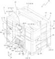
도 1은 이송 가능한 가공 유닛의 사시도이다.
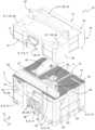
도 2는 전방에서 관찰한, 상단부가 제거된 상태의 이송 가능한 가공 유닛의 사시도이다.
도 3은 후방에서 관찰한, 상단부가 제거된 상태의 이송 가능한 가공 유닛의 사시도이다.
도 4는 덮개가 개방된 이송 가능한 가공 유닛의 사시도이다.
도 5는 이송 가능한 가공 유닛 및 2개의 상자형 용기로 구성되는 스택 배열부의 사시도이다.
도 6은 하부에서 관찰한 이송 가능한 가공 유닛의 사시도이다.
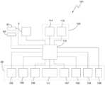
도 7은 제어 장치(101)의 개략적 블록도이다.1 is a perspective view of a transportable processing unit.
Figure 2 is a perspective view of the transportable processing unit with the upper end removed, viewed from the front.
Figure 3 is a perspective view of the transportable processing unit with the upper end removed, viewed from the rear.
Figure 4 is a perspective view of the transportable processing unit with the lid open.
Figure 5 is a perspective view of a stack arrangement consisting of a transportable processing unit and two box-shaped containers.
Figure 6 is a perspective view of the transportable processing unit viewed from below.
Figure 7 is a schematic block diagram of the
도 1 내지 도 4 및 도 6은 이송 가능한 가공 유닛(10)의 사시도이다. 도 5는 이송 가능한 가공 유닛(10)이 부속된 스택 배열부(20)를 도시한다.1 to 4 and FIG. 6 are perspective views of the
이송 가능한 가공 유닛(10)은 도면들에 표시된 z축에 대해 평행하게 연장되는 수직 방향, 도면들에 표시된 x축에 대해 평행하게 진행하는 종 방향 및 도면들에 표시된 y축에 대해 평행하게 진행하는 횡 방향으로 연장된다. x축, y축 및 z축은 서로 직교하여 정렬된다.The
이송 가능한 가공 유닛(10)은 도시된 도면들에서 예시적으로 원형 톱 벤치로서 형성된다. 이에 대해 대안적으로, 이송 가능한 가공 유닛(10)은 예컨대 라우터, 스크롤쏘(scroll saw) 또는 에지 그라인더(edge grinder)와 같은 다른 반고정식 기계로도 형성될 수 있다. 이와 연관하여, 반고정식 기계로서 특히 공작물 가공 시 기저부 상에 세워지며 이송 시 사람이 들기에 적합한 가공 유닛을 지칭해야 한다.The
이송 가능한 가공 유닛(10)은 도면들에 미도시된 공작물을 공구(1)를 이용하여 가공하기 위해 역할한다. 공구(1)는 도면들에서 예시적으로 톱날로서 형성된다.The
이송 가능한 가공 유닛(10)은 기저부 상에 세울 수 있는 상자형 지지 구조물(2)을 포함하고, 이러한 상자형 지지 구조물은 가공할 공작물의 안착을 위해 사용 가능한 공작물-안착 플레이트(4)를 제공하는 하단부(3)를 포함한다. 상자형 지지 구조물(2)은 적합한 방식으로 실질적으로 직육면체형 구조물을 가리키며, 이러한 직육면체형 구조물에서 외부면들, 바람직하게는 전체 외부면들은 실질적으로 닫혀 있다.The
또한, 이송 가능한 가공 유닛(10)은 도 7에서 개략적으로 도시된 구동 장치(5)를 포함한다. 구동 장치(5)는 예컨대 공구(1)의 기계적 구동을 위한 전기 모터를 포함한다. 구동 장치(5)는 논의된 예시에서 완전히 하단부(3) 내에 배치되고, 하단부(3)에서 구동 준비된 상태로 고정됨으로써, 구동 장치(5)는 구동 장치(5)에 의해 구동된 공구(1)에 의하여 공작물의 가공 시 하단부(3) 내에 잔류한다.The
지지 구조물(2)은 지지 구조물-결합 수단(6)을 제공한다. 지지 구조물-결합 수단(6)은 지지 구조물(2)이 적어도 하나의 상자형 몸체(21, 22)와 함께 수직 스택을 형성하는 상태에서 이러한 적어도 하나의 상자형 몸체와 분리 가능하면서 수직으로 인장 강도를 가지는 결합을 제공하기에 적합하다.The support structure (2) provides support structure-coupling means (6). The support structure-coupling means (6) is vertically tensile and separable from the at least one box-shaped body (21, 22) with the support structure (2) forming a vertical stack with the at least one box-shaped body (21, 22). It is suitable for providing a combination with .
이송 가능한 가공 유닛(10)은 지지 구조물-결합 수단(6)으로 인하여 안정적으로, 예컨대 상자형 용기들 및/또는 다른 이송 가능한 가공 유닛들(10)과 같은 상자형 몸체들(21, 22)로 구성되는 스택 내에 부속될 수 있다. 따라서, 이송 가능한 가공 유닛(10)은 스택 내에서 매우 실용적으로 적재되고 및/또는 안전하게 이송될 수 있다. 이로써, 본 발명에 따르는 이송 가능한 가공 유닛(10)은 개선된 취급 가능성을 가진다.The
도면들에서 확인할 수 있는 바와 같이, 이송 가능한 가공 유닛(10)은 특히 시스템 박스의 기본 형상을 가진다. 도면들에 도시된 이송 가능한 가공 유닛(10)은, 다른 시스템 박스들의 스택 내에 부속되도록 형성되며, 이는 예컨대 도 5에 도시된 바와 같다.As can be seen in the drawings, the
이하, 이송 가능한 가공 유닛(10)의 예시적 구성들이 상세하게 설명된다.Hereinafter, exemplary configurations of the
지지 구조물(2)은 상자형으로 형성되고, 서로 직교하여 정렬되는 4개의 둘레 벽을 포함한다. 둘레 벽들은 전면 벽(12), 후면 벽(13), 및 측벽들(25, 26)을 포함한다. 전면 벽(12) 및 후면 벽(13)은 종 방향(x)에 대해 평행하게 정렬되고, 측벽들(25, 26)은 횡 방향(y)에 대해 평행하게 정렬된다.The
도면들에 도시된 이송 가능한 가공 유닛(10)의 지지 구조물(2)은 제거 가능하게 하단부(3)에 취부되는 상단부(16)를 포함한다. 도 1은 상단부(16)가 하단부(3) 상에 안착하여 이러한 하단부에 결합되는 상태에서 가공 유닛(10)을 도시한다. 도 2에서 이송 가능한 가공 유닛(10)은 상단부(16)가 하단부(3)로부터 제거된 상태에서 도시되어 있다.The
도시된 실시 형태에 대하여 대안적으로, 이송 가능한 가공 유닛(10)은 상단부(16)를 포함하지 않고도 형성될 수 있다. 이 경우, 적합한 방식으로 하단부(3)는 전체의 지지 구조물을 나타낼 수 있다. 지지 구조물-결합 수단(6)은 모두 하단부(3)에 구비될 수 있다.Alternatively to the illustrated embodiment, the
지지 구조물-결합 수단(6)은 상부의 지지 구조물-결합 수단(7)을 포함하고, 상부의 지지 구조물-결합 수단은 예시적으로 상단부(16)에 구비된다. 상부의 지지 구조물-결합 수단(7)은 상자형 몸체(21)가 이송 가능한 가공 유닛(10) 상에 적층된 상태에서 상자형 몸체(21)와 분리 가능하면서 수직으로 인장 강도를 가지는 결합을 제공하기에 적합하다. 상부의 지지 구조물-결합 수단(7)은 이동 가능하게 지지되는 잠금 요소(9)를 포함한다. 도시된 예에서, 잠금 요소(9)는 지지 구조물(2)에 회전 가능하게 지지되는 회전 볼트(11)를 포함한다. 회전 볼트(11)는 지지 구조물(2)의 전면 벽(12)에 배치된다. 회전 볼트(11)의 회전 축은 전면 벽(12)에 대하여 직교한다.The support structure-coupling means 6 comprises an upper support structure-coupling means 7, which is exemplarily provided at the
지지 구조물-결합 수단(6)은 하단부(3)에 구비되는 하부의 지지 구조물-결합 수단(8)을 더 포함한다. 하부의 지지 구조물-결합 수단(8)은 이송 가능한 가공 유닛(10)이 상자형 몸체(22) 상에 적층된 상태에서 이러한 상자형 몸체(22)와 분리 가능하면서 수직으로 인장 강도를 가지는 결합을 제공하기에 적합하다. 하부의 지지 구조물-결합 수단(8)은 지지 구조물(2)에 위치 고정적으로 배치되는 적어도 하나의 제1 잠금 앵커 윤곽(14)을 포함한다. 도시된 예에서, 제1 잠금 앵커 윤곽(14)은 지지 구조물(2)의 하단부(3)에 배치된다. 제1 잠금 앵커 윤곽(14)은 지지 구조물(2)의 전면 벽(12)에 위치하고, 종 방향(x)과 관련하여 중앙에서 지지 구조물(2)에 배치된다. 제1 잠금 앵커 윤곽(14)은 잠금 돌출부로서 형성되고, 전면 벽(12)으로부터 돌출해 있다.The support structure-coupling means (6) further includes a lower support structure-coupling means (8) provided at the lower end (3). The lower support structure-coupling means (8) provides a separable and vertical tensile strength connection with the box-shaped body (22) when the transportable processing unit (10) is stacked on the box-shaped body (22). Suitable for providing The lower support structure-coupling means 8 comprises at least one first
잠금 요소(9) 및 제1 잠금 앵커 윤곽(14)은, 서로 포개어 수직으로 적층되는 2개의 이송 가능한 가공 유닛(10)에서 하나의 이송 가능한 가공 유닛(10)의 잠금 요소(9)가 다른 가공 유닛(10)의 제1 잠금 앵커 윤곽(14)과 맞물리며 결합될 수 있는 방식으로 배치된다.The locking
도시된 예시에서, 하부의 지지 구조물-결합 수단(8)은 제1 잠금 앵커 윤곽(14)에 대해 부가적으로 또한 제2 잠금 앵커 윤곽들(15)을 더 포함한다. 제2 잠금 앵커 윤곽들(15)은 또한 잠금 돌출부들로서 형성되나, 제1 잠금 앵커 윤곽(14)과 다르게 전면 벽(12)의 하부 모서리 영역들, 및 후면 벽(13)에 위치하는, 측벽들(25, 26)의 하부의 모서리 영역들 내에 배치된다. 제2 잠금 앵커 윤곽들(15)은, 이송 가능한 가공 유닛(10)을 제2 잠금 앵커 윤곽들(15)에 보완적인 잠금 요소들을 제공하는 용기들 또는 다른 물체들에 결합되게 하는 역할이다. 이송 가능한 가공 유닛(10)이 그와 같은 용기들 또는 물건들에 결합되어야 하는 것이 고려되지 않는다면, 제2 잠금 앵커 윤곽들(15)은 생략될 수 있다.In the example shown, the lower support structure-coupling means 8 further comprises, in addition to the first
지지 구조물-결합 수단(6)은 서두에 언급한 종류의 맞물림 구조물들을 더 포함한다.The support structure-coupling means 6 further comprises engaging structures of the kind mentioned at the beginning.
따라서 상부의 지지 구조물-결합 수단(7)은 지지 구조물(2)의 상측에 분포하여 배치되는 복수의 맞물림 함몰부들(32)을 더 포함한다. 맞물림 함몰부들(32)은 전면 벽(12)의 근방에 배치되는 2개의 제1 맞물림 함몰부들(33) 및 후면 벽(13)의 근방에 배치되는 1개의 제2 맞물림 함몰부(34)를 포함한다.Accordingly, the upper support structure-coupling means 7 further comprises a plurality of engaging
하부의 지지 구조물-결합 수단(8)은 스탠드형 받침부로서 형성되는 4개의 맞물림 돌출부들(82)을 포함하고, 이러한 맞물림 돌출부들은 지지 구조물(2)의 하측의 4개의 모서리 영역들 내에 배치된다. 맞물림 돌출부들(82)은 예컨대 도 6에서 확인할 수 있다. 맞물림 돌출부들(82) 및 맞물림 함몰부들(33, 34)은, 서로 포개어 수직으로 적층되는 2개의 이송 가능한 가공 유닛(10)에서 상부의 이송 가능한 가공 유닛의 맞물림 돌출부들(82)이 하부의 가공 유닛의 맞물림 함몰부들(32)과 맞물리도록 배치된다.The lower support structure-coupling means 8 comprises four engaging
맞물림 돌출부들(82) 및 맞물림 함몰부들(32)은 수직 방향에서의 결합을 위해서도 기여한다. 이는 맞물림 돌출부들(82) 및/또는 맞물림 함몰부들(32)의 리어 그립 구성 요소들이 서로 잠겨지며 맞물림으로써 이루어질 수 있는데, 이는 예컨대 EP 2315701 B1에서 상세히 설명된 바와 같다. 예컨대 제2 맞물림 함몰부(34)는 언더컷된 횡단면을 포함할 수 있고, 제2 맞물림 함몰부(34) 내에 물려 들어가는 대응 맞물림 구조물들(82)은 이에 상응하여 프로파일링된, 예컨대 웨지형으로 프로파일링된 리어 그립부를 포함할 수 있다.The engaging
지지 구조물(2)의 상단부(16)는 캡 형상의 커버로서 형성된다. 도 1에 도시된 상태에서 상단부(16)는 공구-안착 플레이트(4)를 예컨대 완전히 덮는다. 상단부(16)는 수직 방향에서 공작물-안착 플레이트(4)를 넘어 위쪽으로 연장되는 프레임 구조물(17)을 포함한다. 상단부(16) 또는 프레임 구조물(17)의 수평 횡단면은 하단부(3)의 수평 횡단면과 실질적으로 동일한 외부 윤곽을 포함한다. 상단부(16)는 하단부(3)와 일직선상에 배치됨으로써, 상단부는 하단부(3)와 함께 상자형 지지 구조물(2)을 형성한다.The
도 4에서 도시된 바와 같이, 프레임 구조물(17)은 실질적으로 직육면체의 옆면의 형태를 가진다; 즉 프레임 구조물(17)은 서로 직교하여 정렬되는 4개의 둘레벽들을 포함하고, 개방된 하측 및 개방된 상측을 제공한다. 프레임 구조물(17) 및 공구-안착면(4)은 서로 함께 하나의 적재 공간(18)을 한정한다.As shown in Figure 4, the
상단부(16)는 덮개(19)를 포함하고, 이러한 덮개는 프레임 구조물(17)의 개방된 상측에 연관된다. 덮개(19)는 도 1 내지 도 3 및 도 5에 도시된 바와 같이 상단부(16)를 닫기 위해 닫힘 위치로 이동할 수 있거나 도 4에 도시된 바와 같이 상단부를 열어 적재 공간(18)으로의 접근을 허용하기 위해 개방 위치로 이동할 수 있다. 덮개(19)는 후면 벽(13)의 영역 내에서 회동 가능하게 프레임 구조물(17)에 힌지된다. 덮개(19)는 프레임 구조물(17) 상에 완전하게 안착한다. 덮개(19)의 수평 횡단면의 외부 윤곽은 프레임 구조물(17)의 수평 횡단면의 외부 윤곽에 상응한다. 덮개(19)의 상부의 외부면은 지지 구조물(2)의 상측을 나타낸다.The
앞에서 이미 언급하였으며 예시적으로 회전 볼트(11)로서 형성되는 잠금 요소(9)는 덮개(19)에서 지지된다.The locking
논의된 실시 형태에서, 잠금 요소(9)는 지지 구조물(2)과 이러한 지지 구조물(2) 상에 안착한 스택 요소 사이에 수직으로 인장 강도를 가지는 결합을 제공하기 위해 역할할 뿐만 아니라, 또한, 덮개(19)를 잠궈서 이러한 덮개가 개방 위치로 이동할 수 없도록 역할이다. 이러한 목적을 위해, 잠금 요소(9)는 T 형상의 회전 볼트(11)로서 형성되고, 이러한 회전 볼트는 적어도 3개의 서로 다른 위치로 이동할 수 있다.In the embodiment discussed, the locking
도 4는 회전 볼트(11)의 제1 위치를 도시하고, 이러한 제1 위치에서 T 형상의 회전 볼트(11)는 회전 볼트(11)의 하부에서 프레임 구조물(17)에 배치되는 잠금 앵커 윤곽(35)과 맞물리며 결합되지 않는다. 이러한 위치에서 덮개(19)는 개방될 수 있다. 또한, 이 위치에서 이송 가능한 가공 유닛(10) 상에 안착된 (도 4에 미도시된) 스택 요소와의 결합이 제공될 수 있다.4 shows the first position of the
도 2는 회전 볼트(11)의 제2 위치를 도시하고, 이러한 제2 위치에서 회전 볼트(11)는 프레임 구조물(17)에 배치되는 잠금 앵커 윤곽(35)과 결합되어 맞물리나, 스택 요소가 이송 가능한 가공 유닛(10) 상에 안착되면 (도 2에 미도시된) 스택 요소와 맞물리며 결합되지 않는다. 제2 위치에서, 덮개(19)는 잠기고, 이송 가능한 가공 유닛(10) 상에 안착된 스택 요소는 분리되며 제거될 수 있다.Figure 2 shows a second position of the
도 5는 회전 볼트(11)의 제3 위치를 도시하고, 이러한 제3 위치에서 회전 볼트(11)는 프레임 구조물(17)에 구비되는 잠금 앵커 윤곽(35)과 맞물리며 결합됨과 동시에, 안착된 스택 요소(본원에서 상자형 용기(21))에 구비되는 잠금 앵커 윤곽과도 맞물리며 결합된다. 제3 위치에서 덮개(19)는 잠기고, 이송 가능한 가공 유닛(10) 상에 안착된 스택 요소(본원에서 상자형 용기(21))는 이러한 스택 요소에 결합된다.FIG. 5 shows a third position of the
덮개(19)에는 운반용 손잡이(24)가 더 구비된다. 도시된 예시에서, 운반용 손잡이(24)는 덮개(19)의 상측에 배치된다. 운반용 손잡이(24)는 유리한 방식으로, 이러한 운반용 손잡이가 선택적으로 덮개(19)의 상측 쪽으로 회동하며 접근하는 비사용 위치를 차지할 수 있거나 위쪽으로 회동되어 결국 위쪽으로 상측을 넘어 돌출하는 사용 위치를 차지할 수 있도록 형성된다. 바람직하게는, 이는 U 형상의 기본 형상을 가지는 활 형상의 운반용 손잡이를 가리킨다.The
지지 구조물(2)은, 이송 가능한 가공 유닛(10)을 운반용 손잡이(24)를 이용하여 들 수 있도록 형성된다. 특히, 상단부(16)는 수직으로 인장 강도를 가지도록 하단부(3)에 결합됨으로써, 운반용 손잡이(24)를 이용하여 상단부(16)가 들어 올려질 때 또한 하단부도 같이 들어 올려져 상단부(16)에 안정적으로 잔류한다. 도시된 예시에서, 특히 덮개(19)는 수직으로 인장 강도를 가지도록 프레임 구조물(17)에 결합될 수 있고, 프레임 구조물(17)은 수직으로 인장 강도를 가지도록 하단부(3)에 결합될 수 있다. 적합한 방식으로, 프레임 구조물(17)은 전체의 공간 방향에서 인장 강도를 가지도록 하단부(3)에 결합되고 및/또는 덮개(19)는 전체의 공간 방향에서 인장 강도를 가지도록 프레임 구조물(17)에 결합된다.The
덮개(19)의 하측에는 예컨대 교체용 톱날과 같은 교체용 공구의 보관을 위한 보관 배열부(27)가 위치한다. 이에 대해 대안적 또는 부가적으로, 덮개(19)의 하측에는 부자재를 위한 보관 배열부가 구비될 수 있고, 예컨대 스플리팅 웨지(splitting wedge)를 위한 보관 배열부가 구비될 수 있다. 도시된 예시에서, 보관 배열부(27)는 평편한 직사각형의 기본 형상을 포함하고, 후면 벽(13)의 근방에서 덮개(19)의 하측에서 회동 가능하게 힌지된다.On the lower side of the
도 2 내지 도 4에 도시된 바와 같이, 예시적으로 톱날로서 형성되는 공구(1)는 부분적으로 공작물-안착 플레이트(4)의 상부에 배치된다. 공구(1)는 공작물-안착 플레이트(4)의 개구부를 관통하여 물려 들어감으로써, 공구(1)의 일부분은 공작물-안착 플레이트(4)의 상부에 위치한다. 공작물-안착 플레이트(4)의 하부에서 공구(1)는 구동 장치(5)에 취부되거나, 이러한 구동 장치와 결합됨으로써, 이러한 공구는 구동 장치(5)에 의해 구동될 수 있다.As shown in FIGS. 2 to 4 , the
프레임 구조물(17)은 수직 방향에서 위쪽으로, 구동 장치(5)에 취부된 공구(1)를 넘어 연장된다. 이러한 방식으로, 이송 가능한 가공 유닛(10)이 스택 내에 배치되고, 덮개(19)가 닫혀 있을 때에도, 공구(1)는 구동장치(5)에 잔류할 수 있다.The
상단부(16)는 상단부-결합 수단(28)을 제공하고, 하단부(3)는 하단부-결합 수단(29)을 제공한다. 상단부-결합 수단(28) 및 하단부-결합 수단(29)을 이용하여, 상단부(16)는 분리 가능하면서 수직으로 인장 강도를 가지도록 하단부(3)에 결합될 수 있다. 특히, 상단부-결합 수단(28) 및 하단부-결합 수단(29)은 힌지 배열부를 형성할 수 있다.The
도면들에서, 상단부-결합 수단(28)은 예시적으로 지지 구조물(2)의 전면측(12)에 취부되며 예컨대 회전 볼트로서 형성되고 이동 가능하게 지지되는 잠금 요소(31)를 포함한다. 회전 볼트는 전면 벽(12)에 대해 직교하여 정렬되는 회전 축 둘레에서 회전 가능하게 지지된다. 예시적으로, 회전 볼트는 실질적으로 직사각형으로 형성되고, 전면 벽(12)에 대해 평행하게 배치된다. 상단부-결합 수단(28)은 예컨대 후면 벽(13)에 힌지된 2개의 러그(lugs)(36)를 더 포함한다. 러그들(36)은 예컨대 횡 방향에 대해 수직으로 정렬되며 평편한 직사각형인 각각 하나의 기본 몸체(37)를 포함하고, 이러한 기본 몸체의 하측 에지에는 종 방향에 대하여 평행하게 정렬되는 베어링 연장부들(38)이 구비된다.In the figures, the upper end-engaging
하단부-결합 수단(29)은 예시적으로, 하단부(3)에서 전면 벽(12)에서 잠금 앵커 윤곽(39)을 포함한다. 잠금 앵커 윤곽(39)은 전면 벽(12)에 대해 수직으로 돌출하고, 상단부(16)가 하단부(3) 상에 안착된 상태에서 잠금 요소(31)가 결합 위치에 있을 때 잠금 앵커 윤곽(39)과 결합되며 맞물릴 수 있도록 배치된다.The lower end-engaging
하단부-결합 수단(28)은 수용부 배열부들(41)을 하단부(3)에서 더 포함한다. 수용부 배열부들(41)은 지지 구조물(2)의 후면 벽(13)에 배치된다. 수용부 배열부들(41)은, 상단부(15)를 하단부(3)에 결합시키기 위한 베어링 연장부들(39)이 수용부 배열부들(41) 내에 걸려 들어갈 수 있도록 형성된다. 러그들(36) 및 수용부 배열부들(41)을 이용하여 수직 방향(z)에서 서로 이격되며 종 방향(x)으로 정렬되는 2개의 회동 축을 가지는 힌지 배열부가 형성될 수 있다. 힌지 배열부를 이용하여, 상단부(16)는 적어도 후면 벽(13)의 영역 내에서 수직으로 인장 강도를 가지도록 하단부(3)에 결합될 수 있다.The lower part-coupling means (28) further comprises receiver arrangements (41) at the lower part (3). The
앞에서 이미 언급한 바와 같이, 예시적으로 톱날로서 형성되는 공구(1)는 공작물-안착 플레이트(4) 내에 구비된 개구부를 관통하며 물려 들어간다. 톱날은 횡 방향에 대해 평행하게 또는 지지 구조물(2)의 측벽들(25, 26)에 대해 평행하게 정렬된다. 톱날은 보호 캡(42)에 의해 덮인다. 보호 캡(42)은 스플리팅 웨지(43)에 고정되고, 스플리팅 웨지는 개구부를 관통하며 물려 들어가고, 공작물-안착 플레이트(4)의 하부에 배치되는 고정 장치(44)에 고정된다. 톱날 및/또는 스플리팅 웨지(42)는 바람직하게는 후면 벽(13) 내에서 하단부(3)에 구비되는 개구부(46)를 통하여 접근 가능하며, 예컨대 신속 클램핑 시스템(45)을 이용하여 교체될 수 있다.As already mentioned above, the
공작물-안착 플레이트(4)의 상측은 도시된 예시에서 그루브들을 구비한다. 이에 대해 대안적으로, 공작물-안착 플레이트(4)의 상측은 그루브들을 포함하지 않거나 평편하거나 또는 다른 구조화를 포함할 수 있다.The upper side of the workpiece-
톱날은 횡 방향(y)으로 연장되는 가상 선분 위에 놓이며, 이러한 가상 선분은 공작물-안착 플레이트(4)를 종 방향에서 2개의 플레이트부(47, 48)로 분할한다. 톱날은 바람직하게는 종 방향에서 공작물-안착 플레이트(4)에 대해 편심으로 배치됨으로써, 제2 플레이트부(48)는 제1 플레이트부(47) 보다 더 길다. 예컨대, 제2 플레이트부(48)는 종 방향에서 제1 플레이트부(47)의 약 2배일 수 있다. 바람직하게는, 제1 플레이트부(47)는 공구(1)에 대해 상대적으로 고정되는 반면, 제2 플레이트부(48)는 적어도 횡 방향(y)에서 슬라이딩 가능하게 지지됨으로써, 이러한 제2 플레이트부는 공구(1)에 대해 상대적으로 횡 방향(y)으로 슬라이딩될 수 있다. 슬라이딩 가능하게 지지되는 제2 플레이트부(48)를 이용하여, 공작물은 가공 시 공구(1)에 대해 상대적으로 안내되거나 이동될 수 있다. 미도시된 록 오프 장치(lock-off device)를 이용하여, 제2 플레이트부(48)는 공구(1) 또는 하단부(3)에 대해 상대적으로 고정될 수 있다. 이러한 고정은 예컨대 측벽(26)에서 하단부(3)에 구비된 회전 버튼(49)를 통해 조절될 수 있다.The saw blade rests on an imaginary line segment extending in the transverse direction (y), which divides the workpiece-
제2 플레이트부(48)는 특히 이송 위치에서 고정될 수 있으며, 이러한 고정 위치에서 제2 플레이트부는 하단부(3) 또는 상단부(16)와 일직선상에 배치된다. 도면들에서 제2 플레이트부(48)는 이송 위치에서 도시되어 있다. 특히, 이송 위치에서 공작물-안착 플레이트(4)의 수평 횡단면은 하단부(3) 및/또는 상단부(16)의 수평 횡단면과 실질적으로 동일한 외부 윤곽을 포함한다.The
제2 플레이트부(48) 내에서 홈 배열부(51)가 구비되고, 이러한 홈 배열부 내에서 스토퍼 장치(52)가 안내될 수 있다. 스토퍼 장치(52)는 예컨대 앵글 스토퍼(angle stopper)로서 형성되고, 특히 홈 배열부(51) 내에서 안내될 수 있는 고정 요소(53), 고정 요소(53)에 대해 상대적으로 회동 가능한 각도 요소(54) 및 각도 요소(54)에 취부된 가이드 레일(55)을 포함한다. 스토퍼 장치(52)는, 이러한 스토퍼 장치가 적재 공간(18) 내에 부합하고, 특히 스토퍼 장치(52)가 홈 배열부(51) 내에서 안내되는 상태에서 그러하도록 치수 결정된다.A
지지 구조물(2)의 전면 벽(12)은 종 방향(x)에서 2개의 측면의 벽 부들(56, 57) 및 중앙의 벽 부(58)를 포함하고, 이러한 중앙의 벽 부는 측면의 벽 부들(56, 57)에 비해 뒤쪽으로 물러나 있어서 - 즉 횡 방향(y)에서 후면 벽(13) 쪽으로 -, 전면 벽(12)은 종 방향(x)에서 중앙에서 함몰부를 횡 방향(y)에서 포함한다. 도시된 예에서, 함몰부는 전면 벽(12)의 전체 수직 영역에 걸쳐 지지 구조물(2)의 하측으로부터 상측에 이르기까지, 이로써 하단부(3) 및 상단부(16)에 걸쳐 연장된다. 앞에서 논의된 잠금 요소들(11, 31) 및 잠금 앵커 윤곽들(14, 35, 39)은 바람직하게는 중앙의 벽 부(58)에 또는 논의된 함몰부 내에 구비되며, 이는 도면들에 도시된 바와 같다.The
중앙의 벽 부(58)에는 조작 장치(59)가 더 구비된다. 조작 장치(59)는 하단부(3)에 배치되고, 바람직하게는 이송 가능한 가공 유닛(10)의 구동을 위한 파라미터의 조절을 위해 회전 휠들(102, 104) 및/또는 키들(105, 106, 107, 108)을 포함한다. 도시된 예시에서와 같이 이송 가능한 가공 유닛(10)은 원형 벤치 톱을 가리키므로, 조작 장치(59)를 이용하여 예컨대 톱날의 높이 조절 및/또는 각도 조절이 수행될 수 있다. 조작 장치(59)는 특히, 이러한 조작 장치가 횡 방향에서 측면의 벽 부들(56, 57)을 넘어 연장되지 않도록 치수 결정된다.The
전면 벽(12)에는 켜짐 버튼(61) 및 꺼짐 버튼(62)을 포함하는 스위치 장치가 구비된다. 도시된 예에서, 스위치 장치는 측면의 벽 부(56)에 구비된다. 스위치 장치는 하단부(3)에 배치된다. 꺼짐 버튼(62)은 바람직하게는 2개의 서로 다른 위치로 이동할 수 있고 - 꺼짐 버튼(62)이 전면 벽(12) 내에 박히거나 전면벽(12)과 동일 평면으로 배치되는 이송 위치 및 꺼짐 버튼(62)이 전면 벽(12)으로부터 횡 방향으로 앞쪽으로 연장되거나 전면 벽으로부터 횡 방향으로 돌출해 있는 (도면들에 미도시된) 비상 차단 위치로 이동할 수 있다. 비상 차단 위치에서, 꺼짐 버튼(62)은 매우 용이하게 발견되고 작동될 수 있어서, 비상 차단 스위치로서 역할할 수 있다. 따라서, 추가적인 전용 비상 차단 스위치가 구비되지 않아도 된다. 스위치 장치는 특히, 켜짐 버튼(61)을 누를 때 이러한 꺼짐 버튼(62)이 비상 차단 위치를 점하도록 형성된다. 또한, 스위치 장치(62)는 적합한 방식으로 이러한 꺼짐 버튼(62)이 강하게 눌리면 이송 위치로 이동할 수 있고, 강하게 또는 약하게 눌림 시 이송 가능한 가공 유닛(10) 또는 이러한 가공 유닛의 구동 장치(5)의 차단이 야기되도록 형성된다.The
측벽(26)에서 하단부(3) 내에 수용 챔버(63)가 종결되고, 이러한 수용 챔버 내에서 포집 용기(64)가 배치된다. (도면들에 미도시된) 관 배열부에 의하여 공구(1)에서 발생하는 먼지 또는 공작물로부터 떨어져 나온 물질이 포집 용기(64) 내에 안내될 수 있다. 포집 용기(64)는 직접적으로 외부로부터 접근 가능하므로 이러한 포집 용기는 매우 간단하게 비워질 수 있다.The
도 5에는 예시적으로, 이송 가능한 가공 유닛(10)이 2개의 다른 상자형 몸체들(21, 2)을 포함하는 스택 내에 어떻게 배치되는지가 도시되어 있다.5 shows, by way of example, how the
도 5에 도시된 스택 배열부(20)는 앞에서 논의된 이송 가능한 가공 유닛(10), 이송 가능한 가공 유닛(10) 상에 배치되는 상부의 상자형 몸체(21) 및 이송 가능한 가공 유닛(10) 아래에 배치되는 하부의 상자형 몸체(22)를 포함한다. 2개의 상자형 몸체(21, 22)는 도 5에서 예시적으로 상자형 용기들로서 형성된다. 이에 대해 대안적으로, 상자형 몸체들(21, 22) 각각은 추가적 가공 유닛(10)으로서 형성될 수 있다.The
2개의 상자형 몸체들(21, 22)은 이송 가능한 가공 유닛(10)과 함께 수직 스택을 형성한다. 상자형 몸체들(21, 22)은 몸체-결합 수단(23)을 포함하고, 이러한 몸체-결합 수단은 지지 구조물-결합 수단(6)과 연동하여, 상자형 몸체들(21, 22)과 이송 가능한 가공 유닛(10) 사이에 분리 가능하면서 수직으로 인장 강도를 가지는 결합을 제공한다.The two box-shaped
이송 가능한 가공 유닛(10)의 수평 횡단면은 상자형 몸체들(21, 22)의 수평 횡단면과 실질적으로 동일한 외부 윤곽을 포함한다. 이송 가능한 가공 유닛(10)은 상자형 몸체들(21, 22)과 일직선상에 배치됨으로써, 이송 가능한 가공 유닛(10) 및 상자형 몸체들(21, 22)은 서로 함께 실질적으로 직육면체형인 스택을 형성한다.The horizontal cross-section of the
몸체-결합 수단(23)은 지지 구조물-결합 수단(6)과 동일하게 형성될 수 있다. 몸체-결합 수단(23)과 지지 구조물-결합 수단(6) 사이의 결합은 2개의 이송 가능한 가공 유닛들(10)의 지지 구조물-결합 수단들(6) 사이에서의 전술한 결합과 동일한 방식으로 수행될 수 있다.The body-coupling means 23 can be formed identically to the support structure-coupling means 6 . The coupling between the body-coupling means 23 and the support structure-coupling means 6 is in the same manner as the above-described coupling between the support structure-coupling means 6 of the two
특히, 몸체-결합 수단(23)은 바람직하게는 회전 볼트로서 형성되는 잠금 요소(65), 잠금 앵커 윤곽(66) 및 맞물림 구조물들(67)을 포함한다.In particular, the body-engaging
도 5에서 이송 가능한 가공 유닛(10) 상에 안착된 상부의 상자형 몸체(2)의 잠금 앵커 윤곽(55)은 이송 가능한 가공 유닛(10)의 잠금 요소(9)와 맞물리면서 결합된다. 또한, 이송 가능한 가공 유닛(10)의 잠금 요소(9)는 이송 가능한 가공 유닛(10)의 잠금 앵커 윤곽(35)과 맞물리면서 결합된다. 상단부(16)에 구비되는 잠금 요소(31)는 하단부(3)에 구비되는 잠금 앵커 윤곽(39)과 맞물리며 결합된다. 이송 가능한 가공 유닛(10)의 잠금 앵커 윤곽(14)은 하부의 상자형 몸체(22)의 잠금 요소(65)와 맞물리며 결합된다.In FIG. 5 the
또한, 예시적 스택 배열부(20)에서, 앞에서 이미 설명한 맞물림 구조물들은 이송 가능한 가공 유닛(10)과 상자형 몸체들(21, 22) 사이의 결합을 위해 기여한다. 특히, 상부의 상자형 몸체(21)는 이러한 몸체의 하측에서 맞물림 돌출부들을 포함하고, 이러한 맞물림 돌출부들은 이송 가능한 가공 유닛(10)의 전술한 맞물림 돌출부들(82)에 상응하고, 이송 가능한 가공 유닛(10)의 맞물림 함몰부들(32) 내에 물려 들어간다. 또한, 하부의 상자형 몸체(22)는 이러한 몸체의 상측에서 맞물림 함몰부들을 포함하고, 이러한 맞물림 함몰부들은 이송 가능한 가공 유닛(10)의 전술한 맞물림 함몰부들(32)에 상응하며, 이송 가능한 가공 유닛(10)의 맞물림 돌출부들(82)과 맞물린다.Furthermore, in the
도 7은 제어 장치(101)의 개략적 블록도로, 이러한 제어 장치는 이송 가능한 가공 유닛(10) 내에 통합될 수 있다.Figure 7 is a schematic block diagram of a
제어 장치(101)는 앞에서 논의된 조작 장치(59) 및 구동 장치(5)뿐만 아니라 제어 유닛(112) 및 전기적 조절 장치(103)를 포함한다. 또한, 제어 장치(101)는 전술한 켜짐 버튼(61) 및 꺼짐 버튼(62)을 포함할 수 있다.The
조작 장치(59)는 다수의 조작 요소를 포함한다. 예시적으로, 조작 장치(59)는 제1 회전 휠(102) 및 제2 회전 휠(104)을 포함한다. 또한, 조작 장치(59)는 예시적으로 신속 선택 키들(105, 106, 107, 108), 캘리브레이션 키(109) 및 디스플레이(111)를 포함한다.The operating
제어 유닛(112)은 예컨대 마이크로컨트롤러로서 형성된다. 조작 장치(59) 또는 이러한 조작 장치의 조작 요소들은 제어 유닛(112)에 연결된다. 또한, 예시적으로 구동 장치(5) 및 전기적 조절 장치(103)는 제어 유닛(112)에 연결된다. 또한, 켜짐 버튼(61) 및 꺼짐 버튼(62)은 제어 유닛(112)에 연결될 수 있다.The
전기적 조절 장치(103)는 예시적으로 선형 구동부(114) 및 회동 구동부(115)를 포함하고, 이러한 구동부들은 제어 유닛(112)에 의한 제어에 따라 공구(1)를 공작물-안착 플레이트(4)에 대해 상대적으로 포지셔닝하도록 형성된다. 공구(1)의 위치는 예컨대 회전 휠들(102, 104) 및/또는 신속 선택 키들(105, 106, 107, 108)을 통해 조절될 수 있다.The
구동 장치(5)는 예컨대 전기 모터로서, 특히 회전 구동부로서 형성되고, 공구(1)의 기계적 구동을 위해 역할한다. 구동 장치(5)는 하단부(3)에 구동 준비된 상태로 고정됨으로써, 구동 장치(5)는 구동 장치(5)에 의해 구동된 공구(1)에 의한 공작물(1)의 가공 시 하단부(3) 내에 잔류한다. 구동 장치에 의한 공구(1)의 구동은 예컨대 켜짐 버튼(61)의 작동에 의해 시작될 수 있고, 꺼짐 버튼(62)의 작동에 의해 정지될 수 있다.The
Claims (16)
Translated fromKorean상기 이송 가능한 가공 유닛(10)은 기저부 상에 세울 수 있으며 가공할 공작물의 안착을 위해 사용 가능한 공작물-안착 플레이트(4)를 제공하는 하단부(3)를 구비한 상자형 지지 구조물(2) 및
제거 가능하게 상기 하단부(3)에 취부되며 캡 형상의 커버로서 형성되는 상단부(16) 및 상기 공구(1)의 기계적 구동을 위한 구동 장치(5)로서, 상기 구동 장치는 적어도 부분적으로 상기 하단부(3) 내에 배치되고 상기 하단부에 구동 준비된 상태로 고정됨으로써, 상기 구동 장치(5)는 상기 구동 장치(5)에 의해 구동된 공구(1)에 의한 상기 공작물의 가공 시 적어도 부분적으로 상기 하단부(3) 내에 잔류하는, 상기 구동 장치(5)를 포함하는, 스택 배열부(20)에 있어서,
상기 지지 구조물(2)은 지지 구조물-결합 수단(6)을 제공하고, 상기 지지 구조물-결합 수단은 상기 지지 구조물(2)이 적어도 하나의 상자형 몸체(21; 22)와 함께 수직 스택을 형성하는 상태에서 상기 적어도 하나의 상자형 몸체(21; 22)와 분리 가능하면서 수직으로 인장 강도를 가지는 결합을 제공하기에 적합하고, 상기 지지 구조물-결합 수단(6)은 상부의 지지 구조물-결합 수단(7)을 포함하고, 상기 상부의 지지 구조물-결합 수단은 상단부(16)에 구비되고, 상자형 몸체(21)가 상기 이송 가능한 가공 유닛(10) 상에 적층된 상태에서 상기 상자형 몸체(21)와 분리 가능하면서 수직으로 인장 강도를 가지는 결합을 제공하기에 적합하고, 상기 지지 구조물-결합 수단(6)은 하부의 지지 구조물-결합 수단(8)을 포함하고, 상기 하부의 지지 구조물-결합 수단은 상기 이송 가능한 가공 유닛(10)이 상기 상자형 몸체(22) 상에 적층된 상태에서 상기 상자형 몸체(22)와 분리 가능하면서 수직으로 인장 강도를 가지는 결합을 제공하기에 적합하고, 상기 상자형 몸체(21, 22)는 상기 이송 가능한 가공 유닛(10)의 위 또는 아래에 배치되어, 상기 이송 가능한 가공 유닛(10)과 함께 수직 스택을 형성하고,
상기 상자형 몸체(21, 22)는 몸체-결합 수단(23)을 포함하고, 상기 몸체-결합 수단은 상기 지지 구조물-결합 수단(6)과 연동하여, 상기 상자형 몸체(21; 22)와 상기 이송 가능한 가공 유닛(10) 사이에 분리 가능하면서 수직으로 인장 강도를 가지는 결합을 제공하는 것을 특징으로 하는 스택 배열부(20).A stack arrangement (20) comprising a transportable machining unit (10) for machining a workpiece using a tool (1) and at least one box-shaped body (21, 22),
The transportable machining unit (10) comprises a box-shaped support structure (2) which can stand on a base and has a lower part (3) which provides a workpiece-rest plate (4) available for seating the workpiece to be machined;
An upper part (16) removably mounted on the lower part (3) and formed as a cap-shaped cover and a driving device (5) for mechanically driving the tool (1), wherein the driving device is at least partially connected to the lower part ( 3) and being fixed in a ready-to-drive state on the lower end, the drive device 5 is at least partially positioned on the lower end 3 during processing of the workpiece by the tool 1 driven by the drive device 5. ) in a stack arrangement (20), comprising the drive device (5), remaining in the stack arrangement (20),
The support structure (2) provides support structure-coupling means (6), wherein the support structure (2) forms a vertical stack with at least one box-shaped body (21; 22). Suitable for providing a separable and vertically tensile connection with the at least one box-shaped body (21; 22) in a state wherein the support structure-coupling means (6) is an upper support structure-coupling means. (7), wherein the upper support structure-coupling means is provided at the upper end (16), and the box-shaped body (21) is stacked on the transportable processing unit (10). 21), the support structure-coupling means (6) comprises a lower support structure-coupling means (8), and the lower support structure-coupling means (8) is suitable for providing a separable connection with the vertical tensile strength. The coupling means is suitable for providing a vertically tensile strength bond that is separable from the box-shaped body 22 when the transportable processing unit 10 is stacked on the box-shaped body 22, The box-shaped bodies (21, 22) are disposed above or below the transportable processing unit (10), forming a vertical stack with the transportable processing unit (10),
The box-shaped bodies (21, 22) include body-coupling means (23), which are linked with the support structure-coupling means (6), to form the box-shaped bodies (21; 22) and A stack arrangement (20), characterized in that it provides a separable, vertically tensile strength bond between the transportable processing units (10).
상기 지지 구조물-결합 수단(6), 또는 상기 상부의 지지 구조물-결합 수단(7)은 이동 가능하게 지지되는 잠금 요소(9)를 포함하는 것을 특징으로 하는 스택 배열부(20).According to claim 1,
Stack arrangement (20), characterized in that the support structure-engagement means (6) or the upper support structure-engagement means (7) comprise a movably supported locking element (9).
상기 지지 구조물-결합 수단(6), 또는 상기 하부의 지지 구조물-결합 수단(8)은 상기 지지 구조물(2)에 위치 고정적으로 배치되는 적어도 하나의 잠금 앵커 윤곽(14; 15)을 포함하는 것을 특징으로 하는 스택 배열부(20).According to claim 1,
The support structure-coupling means (6) or the lower support structure-coupling means (8) comprise at least one locking anchor contour (14; 15) positioned fixedly on the support structure (2). Characterized by a stack arrangement unit (20).
상기 상단부(16)는 수직 방향에서 상기 공작물-안착 플레이트(4)를 넘어 위쪽으로 연장되는 프레임 구조물(17)을 포함하는 것을 특징으로 하는 스택 배열부(20).According to claim 1,
Stack arrangement (20), characterized in that the upper part (16) comprises a frame structure (17) extending upwardly beyond the workpiece-rest plate (4) in a vertical direction.
상기 상단부(16)의 수평 횡단면, 또는 상기 프레임 구조물(17)의 수평 횡단면은 상기 하단부(3)의 수평 횡단면과 실질적으로 동일한 외부 윤곽을 포함하는 것을 특징으로 하는 스택 배열부(20).According to claim 4,
Stack arrangement (20), characterized in that the horizontal cross-section of the upper part (16) or the horizontal cross-section of the frame structure (17) has an external contour substantially the same as the horizontal cross-section of the lower part (3).
상기 공구(1)는 상기 구동 장치(5)에 취부되고, 적어도 부분적으로 상기 공작물-안착 플레이트(4)의 상부에 배치되고, 상기 프레임 구조물(17)은 수직 방향에서 위쪽으로 상기 구동 장치(5)에 취부된 공구(1)를 넘어 연장되는 것을 특징으로 하는 스택 배열부(20).According to claim 4,
The tool 1 is mounted on the drive device 5 and is at least partially disposed on the upper part of the workpiece-seating plate 4, and the frame structure 17 extends upward in the vertical direction toward the drive device 5. ) Stack arrangement (20), characterized in that it extends beyond the tool (1) mounted on it.
상기 하부의 지지 구조물-결합 수단(8)은 상기 하단부(3)에 구비되는 것을 특징으로 하는 스택 배열부(20).According to claim 4,
Stack arrangement (20), characterized in that the lower support structure-coupling means (8) is provided in the lower part (3).
상기 상단부(16)는 상기 하단부(3)에 취부된 상태에서 상기 공작물-안착 플레이트(4)를 덮는 것을 특징으로 하는 스택 배열부(20).According to claim 4,
The stack arrangement part (20), wherein the upper part (16) covers the workpiece-seating plate (4) when attached to the lower part (3).
상기 프레임 구조물(17) 및 상기 공작물-안착 플레이트(4)는 서로 함께 적재 공간(18)을 한정하고, 상기 상단부(16)는 제거 가능한 특성 및 회동 가능한 특성 중 하나 이상을 갖는 덮개(19)를 제공하고, 상기 덮개는 상기 프레임 구조물(17)에 취부되고, 상기 덮개는 개방 위치에서 상기 적재 공간(18)으로의 접근을 허용하는 것을 특징으로 하는 스택 배열부(20).According to claim 4,
The frame structure 17 and the workpiece-rest plate 4 together define a loading space 18, and the upper end 16 has a cover 19 having at least one of a removable feature and a pivotable feature. A stack arrangement (20), wherein the cover is mounted on the frame structure (17), and the cover allows access to the loading space (18) in an open position.
상기 지지 구조물(2)에, 또는 상기 상단부(16)에, 또는 상기 덮개(19)에 구비되는 운반용 손잡이(24)를 포함하고, 상기 지지 구조물(2)은 상기 이송 가능한 가공 유닛(10)을 상기 운반용 손잡이(24)를 이용하여 들 수 있도록 형성되는 것을 특징으로 하는 스택 배열부(20).According to clause 9,
It includes a carrying handle 24 provided on the support structure 2, the upper part 16, or the cover 19, and the support structure 2 supports the transportable processing unit 10. A stack arrangement unit (20), characterized in that it is formed to be lifted using the carrying handle (24).
상기 이송 가능한 가공 유닛(10)의 수평 횡단면은 상기 상자형 몸체(21; 22)의 수평 횡단면과 실질적으로 동일한 외부 윤곽을 포함하고, 상기 이송 가능한 가공 유닛(10)은 상기 상자형 몸체(21; 22)와 일직선상에 배치됨으로써, 상기 이송 가능한 가공 유닛(10) 및 상기 상자형 몸체(21; 22)는 서로 함께 실질적으로 직육면체 형인 스택을 형성하는 것을 특징으로 하는 스택 배열부(20).According to claim 1,
The horizontal cross-section of the transportable processing unit 10 has an external contour substantially identical to the horizontal cross-section of the box-shaped body 21; 22, and the transportable processing unit 10 includes the box-shaped body 21; Stack arrangement (20), characterized in that by being arranged in line with (22), the transportable processing unit (10) and the box-shaped body (21; 22) together form a substantially rectangular parallelepiped stack.
상기 이송 가능한 가공 유닛(10)은 원형 톱 벤치인 것을 특징으로 하는 스택 배열부(20).According to claim 1,
Stack arrangement (20), characterized in that the transferable machining unit (10) is a circular saw bench.
상기 잠금 요소(9)는 상기 지지 구조물(2)에 회전 가능하게 지지되는 회전 볼트(11)를 포함하고, 회전 축은 상기 회전 볼트가 배치되는 상기 지지 구조물(2)의 둘레 벽(12)에 대해 직교하는 것을 특징으로 하는 스택 배열부(20).According to claim 2,
The locking element 9 comprises a rotary bolt 11 rotatably supported on the support structure 2, the axis of rotation relative to the peripheral wall 12 of the support structure 2 on which the rotary bolt is arranged. A stack arrangement unit (20) characterized in that it is orthogonal.
상기 상자형 몸체는 상기 이송 가능한 가공 유닛(10) 상에 배치되는 상부의 상자형 용기이고, 상기 스택 배열부(20)는 상기 이송 가능한 가공 유닛(10) 아래에 배치되는 하부의 상자형 몸체를 더 포함하고, 상기 2개의 상자형 용기는 상기 이송 가능한 가공 유닛(10)과 함께 수직 스택을 형성하고, 몸체-결합 수단(23)을 포함하고, 상기 몸체-결합 수단은 상기 지지 구조물-결합 수단(6)과 연동하여, 상자형 용기들과 상기 이송 가능한 가공 유닛(10) 사이에 분리 가능하면서 수직으로 인장 강도를 가지는 결합을 제공하는 것을 특징으로 하는 스택 배열부(20).The method according to any one of claims 1 to 13,
The box-shaped body is an upper box-shaped container disposed on the transferable processing unit 10, and the stack arrangement 20 is a lower box-shaped body disposed below the transferable processing unit 10. Further comprising: the two box-shaped containers form a vertical stack with the transportable processing unit (10), comprising body-coupling means (23), wherein the body-coupling means comprises the support structure-coupling means In conjunction with (6), a stack arrangement (20) characterized in that it provides a separable and vertically tensile strength bond between the box-shaped containers and the transportable processing unit (10).
2개의 상자형 용기는 시스템 박스로서 형성되는 것을 특징으로 하는 스택 배열부(20).According to claim 12,
Stack arrangement (20), characterized in that the two box-shaped containers are formed as a system box.
2개의 상자형 용기는 수동 전동 공구, 부자재 및 소모재 중 하나 이상의 보관을 위한 모듈형 공구 박스들로서 형성되는 것을 특징으로 하는 스택 배열부(20).According to claim 13,
Stack arrangement unit 20, wherein the two box-shaped containers are formed as modular tool boxes for storage of one or more of manual power tools, subsidiary materials, and consumables.
Applications Claiming Priority (1)
| Application Number | Priority Date | Filing Date | Title |
|---|---|---|---|
| PCT/EP2016/073743WO2018065042A1 (en) | 2016-10-05 | 2016-10-05 | Transportable machining unit and stacking arrangement |
Publications (2)
| Publication Number | Publication Date |
|---|---|
| KR20190065334A KR20190065334A (en) | 2019-06-11 |
| KR102686076B1true KR102686076B1 (en) | 2024-07-17 |
Family
ID=57104012
Family Applications (1)
| Application Number | Title | Priority Date | Filing Date |
|---|---|---|---|
| KR1020197012383AActiveKR102686076B1 (en) | 2016-10-05 | 2016-10-05 | Transportable machining units and stack arrangements |
Country Status (6)
| Country | Link |
|---|---|
| US (1) | US20190232484A1 (en) |
| EP (1) | EP3523077B1 (en) |
| JP (1) | JP6895514B2 (en) |
| KR (1) | KR102686076B1 (en) |
| CN (1) | CN110023017B (en) |
| WO (1) | WO2018065042A1 (en) |
Families Citing this family (6)
| Publication number | Priority date | Publication date | Assignee | Title |
|---|---|---|---|---|
| WO2023064922A1 (en) | 2021-10-15 | 2023-04-20 | Makita U.S.A., Inc. | Modular storage system with storage box connectivity and external box features |
| USD1020146S1 (en)* | 2021-11-05 | 2024-03-26 | Festool Gmbh | Vacuum cleaner |
| DE102022201168A1 (en) | 2022-02-03 | 2023-08-03 | Festool Gmbh | Sawing apparatus, stacking arrangement, cover arrangement, transport arrangement and method |
| USD1059829S1 (en) | 2022-10-14 | 2025-02-04 | Makita U.S.A., Inc. | Storage box |
| US20250309665A1 (en)* | 2024-03-28 | 2025-10-02 | Keith Rouse | Battery charging toolbox assembly |
| DE102024110007A1 (en) | 2024-04-10 | 2025-10-16 | Truma Gerätetechnik GmbH & Co. KG | Modular box for a camper and modular extension system for a camper with such a box |
Citations (1)
| Publication number | Priority date | Publication date | Assignee | Title |
|---|---|---|---|---|
| US20100116261A1 (en) | 2008-07-03 | 2010-05-13 | Mitch Fairweather | Chop Saw with Dust Collection System |
Family Cites Families (24)
| Publication number | Priority date | Publication date | Assignee | Title |
|---|---|---|---|---|
| US2695210A (en)* | 1953-12-02 | 1954-11-23 | Century Display Mfg Company In | Tool carrying case |
| US3556623A (en)* | 1968-09-26 | 1971-01-19 | Stanley Works | Combination carrying case and tool-holder for portable power tools |
| US6347847B1 (en)* | 1998-02-02 | 2002-02-19 | 500 Group Inc. | Rolling containers assembly |
| IL128303A (en)* | 1998-02-02 | 2002-02-10 | 500 Group Inc | Rolling containers assembly |
| JP2001121509A (en)* | 1999-10-29 | 2001-05-08 | Einosuke Negishi | Portable cutting device with dust collecting function |
| US6494198B1 (en)* | 2001-04-24 | 2002-12-17 | Yuehting Chen | Stone cutter |
| US20060116787A1 (en)* | 2002-04-18 | 2006-06-01 | Etter Mark A | Power tool control system |
| DE20314301U1 (en)* | 2003-09-17 | 2004-02-26 | Berner Gmbh | Stackable tool case |
| US7066069B2 (en)* | 2004-03-09 | 2006-06-27 | Rexon Industrial Corp., Ltd. | Tilt angle display device for a circular saw machine |
| US7290655B1 (en)* | 2004-05-24 | 2007-11-06 | Wood Michael D | Carrying case assembly for a power tool and its associated method of use |
| DE202004009123U1 (en) | 2004-06-09 | 2004-09-09 | Proxxon S.A. | Circular bench saw has worktable hinged to housing, so that machine frame can be pivoted upwards for easy access for maintenance etc. |
| US7752699B1 (en)* | 2004-06-15 | 2010-07-13 | Fruzzetti Jr Francis Paul | Tubing preparation machine |
| US7299730B2 (en)* | 2005-10-11 | 2007-11-27 | Hummel Joseph S | Saw calibration wheel |
| DE102008001727A1 (en)* | 2008-05-13 | 2009-11-19 | Robert Bosch Gmbh | machine tool |
| US8875888B2 (en)* | 2009-06-29 | 2014-11-04 | Tts Tooltechnic Systems Ag & Co. Kg | Stackable container assembly with reciprocal locking of the stacked containers |
| US8327744B2 (en)* | 2009-08-26 | 2012-12-11 | Robert Bosch Gmbh | Table saw with reset mechanism |
| US8567796B2 (en)* | 2009-09-01 | 2013-10-29 | The Stanley Works Israel Ltd. | Rolling container assembly with adjustable storage units |
| US20110100183A1 (en)* | 2009-11-03 | 2011-05-05 | John Tomaino | Table saw blade height and angle adjustment mechanism |
| US8657307B2 (en)* | 2011-06-22 | 2014-02-25 | The Stanley Works Israel Ltd. | Modular rolling container assembly |
| US9403224B1 (en)* | 2011-06-30 | 2016-08-02 | Carlos Silva | Combined chop saw and work table and associated use thereof |
| DE102012017385A1 (en)* | 2012-09-01 | 2014-03-06 | Man Truck & Bus Ag | Locking device for locking and unlocking a tiltable cab for a commercial vehicle |
| US9393684B2 (en)* | 2014-04-01 | 2016-07-19 | Meridian International Co., Ltd. | Toolbox |
| DE202015106714U1 (en)* | 2015-12-09 | 2016-01-11 | Compass Corp. | tool box |
| US10906110B2 (en)* | 2017-04-28 | 2021-02-02 | Transform Sr Brands Llc | Power tool with integrated measurement device and associated methods |
- 2016
- 2016-10-05EPEP16777987.5Apatent/EP3523077B1/enactiveActive
- 2016-10-05CNCN201680089905.8Apatent/CN110023017B/enactiveActive
- 2016-10-05WOPCT/EP2016/073743patent/WO2018065042A1/ennot_activeCeased
- 2016-10-05KRKR1020197012383Apatent/KR102686076B1/enactiveActive
- 2016-10-05JPJP2019518196Apatent/JP6895514B2/enactiveActive
- 2016-10-05USUS16/339,428patent/US20190232484A1/ennot_activeAbandoned
Patent Citations (1)
| Publication number | Priority date | Publication date | Assignee | Title |
|---|---|---|---|---|
| US20100116261A1 (en) | 2008-07-03 | 2010-05-13 | Mitch Fairweather | Chop Saw with Dust Collection System |
Also Published As
| Publication number | Publication date |
|---|---|
| WO2018065042A1 (en) | 2018-04-12 |
| JP2019529144A (en) | 2019-10-17 |
| KR20190065334A (en) | 2019-06-11 |
| EP3523077A1 (en) | 2019-08-14 |
| JP6895514B2 (en) | 2021-06-30 |
| CN110023017B (en) | 2024-04-02 |
| EP3523077B1 (en) | 2023-08-30 |
| US20190232484A1 (en) | 2019-08-01 |
| CN110023017A (en) | 2019-07-16 |
Similar Documents
| Publication | Publication Date | Title |
|---|---|---|
| KR102686076B1 (en) | Transportable machining units and stack arrangements | |
| KR102627529B1 (en) | Transportable processing units, structures and stack arrangements | |
| US7108131B2 (en) | Case, particularly a machine tool case | |
| US5507385A (en) | Multipurpose storage bin | |
| US7367571B1 (en) | Tool and task box storage, transport, and workbench system | |
| TWI624408B (en) | Box and method for manipulating the box | |
| US5595228A (en) | Utility box incorporating an integral clamping vise | |
| CN101522376B (en) | Tool box apparatus for mounting electric tool to provide work station | |
| US12030064B2 (en) | Cyclone pre-separator and arrangement | |
| US20190315515A1 (en) | Stackable system container | |
| DK2551210T3 (en) | Stacking device of various containers | |
| EP3944929B1 (en) | Workbench-hand truck assembly | |
| JP2018503527A (en) | Manual tool trunk, positioning unit, system and method for positioning | |
| WO2018055575A1 (en) | Toolbox with accessory tracks | |
| CN217394891U (en) | Modular workstation | |
| JP2023113580A (en) | Saw device, stack unit, cover unit, conveyance unit and method | |
| US11958180B2 (en) | Rotary tool | |
| US20190283154A1 (en) | Transportable machining unit | |
| US20250135628A1 (en) | Transport box, stack arrangement, transport arrangement, motor vehicle and method | |
| US20250296219A1 (en) | Working apparatus having a transportable trestle | |
| GB2442713A (en) | Portable work apparatus | |
| GB2336799A (en) | Portable workbench provided with tool box | |
| AU4450099A (en) | Mobil work station |
Legal Events
| Date | Code | Title | Description |
|---|---|---|---|
| PA0105 | International application | Patent event date:20190429 Patent event code:PA01051R01D Comment text:International Patent Application | |
| PG1501 | Laying open of application | ||
| A201 | Request for examination | ||
| PA0201 | Request for examination | Patent event code:PA02012R01D Patent event date:20210817 Comment text:Request for Examination of Application | |
| E902 | Notification of reason for refusal | ||
| PE0902 | Notice of grounds for rejection | Comment text:Notification of reason for refusal Patent event date:20240216 Patent event code:PE09021S01D | |
| E701 | Decision to grant or registration of patent right | ||
| PE0701 | Decision of registration | Patent event code:PE07011S01D Comment text:Decision to Grant Registration Patent event date:20240521 | |
| GRNT | Written decision to grant | ||
| PR0701 | Registration of establishment | Comment text:Registration of Establishment Patent event date:20240715 Patent event code:PR07011E01D | |
| PR1002 | Payment of registration fee | Payment date:20240715 End annual number:3 Start annual number:1 | |
| PG1601 | Publication of registration |