KR102686041B1 - Wireless power transmission module and electronic device having the same - Google Patents
Wireless power transmission module and electronic device having the sameDownload PDFInfo
- Publication number
- KR102686041B1 KR102686041B1KR1020170020128AKR20170020128AKR102686041B1KR 102686041 B1KR102686041 B1KR 102686041B1KR 1020170020128 AKR1020170020128 AKR 1020170020128AKR 20170020128 AKR20170020128 AKR 20170020128AKR 102686041 B1KR102686041 B1KR 102686041B1
- Authority
- KR
- South Korea
- Prior art keywords
- magnetic sheet
- wireless power
- power transmission
- transmission module
- coil
- Prior art date
- Legal status (The legal status is an assumption and is not a legal conclusion. Google has not performed a legal analysis and makes no representation as to the accuracy of the status listed.)
- Active
Links
Images


Classifications
- H—ELECTRICITY
- H01—ELECTRIC ELEMENTS
- H01F—MAGNETS; INDUCTANCES; TRANSFORMERS; SELECTION OF MATERIALS FOR THEIR MAGNETIC PROPERTIES
- H01F38/00—Adaptations of transformers or inductances for specific applications or functions
- H01F38/14—Inductive couplings
- H—ELECTRICITY
- H01—ELECTRIC ELEMENTS
- H01F—MAGNETS; INDUCTANCES; TRANSFORMERS; SELECTION OF MATERIALS FOR THEIR MAGNETIC PROPERTIES
- H01F27/00—Details of transformers or inductances, in general
- H01F27/24—Magnetic cores
- H01F27/245—Magnetic cores made from sheets, e.g. grain-oriented
- H—ELECTRICITY
- H01—ELECTRIC ELEMENTS
- H01F—MAGNETS; INDUCTANCES; TRANSFORMERS; SELECTION OF MATERIALS FOR THEIR MAGNETIC PROPERTIES
- H01F27/00—Details of transformers or inductances, in general
- H01F27/28—Coils; Windings; Conductive connections
- H01F27/29—Terminals; Tapping arrangements for signal inductances
- H01F27/292—Surface mounted devices
- H—ELECTRICITY
- H02—GENERATION; CONVERSION OR DISTRIBUTION OF ELECTRIC POWER
- H02J—CIRCUIT ARRANGEMENTS OR SYSTEMS FOR SUPPLYING OR DISTRIBUTING ELECTRIC POWER; SYSTEMS FOR STORING ELECTRIC ENERGY
- H02J50/00—Circuit arrangements or systems for wireless supply or distribution of electric power
Landscapes
- Engineering & Computer Science (AREA)
- Power Engineering (AREA)
- Computer Networks & Wireless Communication (AREA)
- Charge And Discharge Circuits For Batteries Or The Like (AREA)
Abstract
Translated fromKoreanDescription
Translated fromKorean본 발명은 무선 전력 전송 모듈 및 이를 구비하는 전자 기기에 관한 것이다.
The present invention relates to a wireless power transmission module and an electronic device equipped with the same.
무선 전력 전송(Wireless Power Transfer) 기술은 스마트폰, 웨어러블 기기를 비롯한 다양한 통신 / 휴대 단말기 등을 포함하는 다양한 전자기기에 폭넓게 적용되고 있는 추세이다.Wireless Power Transfer technology is being widely applied to various electronic devices, including smartphones, wearable devices, and various communication/portable terminals.
무선 전력 전송 기술에는 크게 코일을 이용한 전자기 유도방식과, 공진(Resonance)을 이용하는 공진 방식 등으로 구분되고 있다. 이 중 자기 유도에 의한 전력 전송 방법은 1차 코일과 2차 코일 간의 전력을 전송하는 방식이다.Wireless power transmission technology is largely divided into electromagnetic induction using a coil and resonance using resonance. Among these, the power transmission method by magnetic induction is a method of transmitting power between the primary coil and the secondary coil.
코일에 자석을 움직이면 유도 전류가 발생하는데, 이를 이용하여 송신단에서 자기장을 발생시키고 수신단에서 자기장의 변화에 따라 전류가 유도되어 에너지를 만들어 낸다. 이러한 현상을 자기 유도 현상이라고 일컬으며 이를 이용한 전력 전송 방법은 에너지 전송 효율이 뛰어나다.When a magnet is moved in a coil, an induced current is generated. Using this, a magnetic field is generated at the transmitting end, and a current is induced according to the change in the magnetic field at the receiving end, creating energy. This phenomenon is called a magnetic induction phenomenon, and the power transmission method using this has excellent energy transmission efficiency.
한편, 종래의 무선 전력 전송 모듈은 페라이트를 이용한 자성 시트를 이용하여 자로를 형성하고 있다.Meanwhile, a conventional wireless power transmission module uses a magnetic sheet using ferrite to form a magnetic path.
그러나, 이러한 종래의 페라이트 자성 시트는 진동 등에 의해 분진이나 크랙이 쉽게 발생된다. 예를 들어, 무선 전력 전송 모듈이 차량에 탑재되는 경우, 차량에 의해 무선 전력 전송 모듈에 인가되는 진동으로 인해, 자성 시트에서 분진이나 크랙이 쉽게 발생되며, 이로 인해 무선 전력 전송 모듈이 제대로 동작하지 못하는 상황이 발생될 수 있다.
However, such conventional ferrite magnetic sheets easily generate dust or cracks due to vibration, etc. For example, when the wireless power transmission module is mounted on a vehicle, dust or cracks are easily generated in the magnetic sheet due to vibration applied to the wireless power transmission module by the vehicle, which prevents the wireless power transmission module from operating properly. Situations may arise where this is not possible.
본 발명의 목적은 자성 시트에서 분진이나 크랙이 발생하는 것을 최소화할 수 있는 무선 전력 전송 모듈 및 이를 구비하는 전자 기기를 제공하는 데에 있다.
The purpose of the present invention is to provide a wireless power transmission module that can minimize dust or cracks from magnetic sheets and an electronic device equipped with the same.
본 발명의 실시예에 따른 무선 전력 전송 모듈은, 적어도 하나의 코일을 포함하는 코일부 및 상기 코일부의 일측에 배치되는 자성부를 포함하며, 상기 자성부는 편평한 판 형상의 자성 시트와, 상기 자성 시트를 부분적으로 덮으며 상기 자성 시트에 결합되는 프레임을 포함할 수 있다.A wireless power transmission module according to an embodiment of the present invention includes a coil unit including at least one coil and a magnetic unit disposed on one side of the coil unit, wherein the magnetic unit includes a flat plate-shaped magnetic sheet, and the magnetic sheet. It may include a frame that partially covers and is coupled to the magnetic sheet.
또한 본 발명의 실시예에 따른 전자 기기는, 적어도 하나의 코일을 포함하는 코일부와 상기 코일부의 일측에 배치되는 자성부를 포함하며, 상기 자성부는 편평한 판 형상의 자성 시트와, 상기 자성 시트를 부분적으로 덮으며 상기 자성 시트에 결합되는 프레임을 포함하는 무선 전력 전송 모듈 및 상기 무선 전력 전송 모듈을 내부에 수용하는 케이스를 포함할 수 있다.
Additionally, an electronic device according to an embodiment of the present invention includes a coil portion including at least one coil and a magnetic portion disposed on one side of the coil portion, wherein the magnetic portion includes a flat plate-shaped magnetic sheet and the magnetic sheet. It may include a wireless power transmission module that partially covers it and includes a frame coupled to the magnetic sheet, and a case that accommodates the wireless power transmission module therein.
본 발명의 실시예에 따른 무선 전력 전송 모듈은 지속적으로 무선 전력 전송 모듈에 진동이 유입되더라도 자성 시트가 파손되거나 자성 시트에 크랙이 발생되는 것을 억제할 수 있다.The wireless power transmission module according to an embodiment of the present invention can prevent the magnetic sheet from being damaged or cracks occurring even if vibration continuously flows into the wireless power transmission module.
또한 자성 시트에서 분진이 발생되더라도 이러한 분진이 전압 변환부 측으로 유입되는 것을 억제할 수 있다.
Additionally, even if dust is generated from the magnetic sheet, such dust can be prevented from flowing into the voltage converter.
도 1은 본 발명의 실시예에 따른 전자 기기들을 개략적으로 도시한 사시도.
도 2는 도 1의 I-I′에 따른 단면도.
도 3은 도 1에 도시된 충전 기기의 분해 사시도.
도 4는 본 발명의 실시예에 따른 무선 전력 전송 모듈을 개략적으로 도시한 사시도.
도 5는 도 4의 II-II′에 따른 단면도.
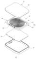
도 6은 도 4에 도시된 무선 전력 전송 모듈의 분해 사시도.1 is a perspective view schematically showing electronic devices according to an embodiment of the present invention.
Figure 2 is a cross-sectional view taken along line II' of Figure 1;
Figure 3 is an exploded perspective view of the charging device shown in Figure 1.
Figure 4 is a perspective view schematically showing a wireless power transmission module according to an embodiment of the present invention.
Figure 5 is a cross-sectional view taken along line II-II' of Figure 4.
FIG. 6 is an exploded perspective view of the wireless power transmission module shown in FIG. 4.
본 발명의 상세한 설명에 앞서, 이하에서 설명되는 본 명세서 및 청구범위에 사용된 용어나 단어는 통상적이거나 사전적인 의미로 한정해서 해석되어서는 아니 되며, 발명자는 그 자신의 발명을 가장 최선의 방법으로 설명하기 위해 용어의 개념으로 적절하게 정의할 수 있다는 원칙에 입각하여 본 발명의 기술적 사상에 부합하는 의미와 개념으로 해석되어야만 한다. 따라서 본 명세서에 기재된 실시예와 도면에 도시된 구성은 본 발명의 가장 바람직한 실시예에 불과할 뿐, 본 발명의 기술적 사상을 모두 대변하는 것은 아니므로, 본 출원시점에 있어서 이들을 대체할 수 있는 다양한 균등물과 변형 예들이 있을 수 있음을 이해하여야 한다.Prior to the detailed description of the present invention, the terms and words used in the specification and claims described below should not be construed as limited to their ordinary or dictionary meanings, and the inventor should use his/her invention in the best possible manner. In order to explain, it must be interpreted as meaning and concept consistent with the technical idea of the present invention based on the principle that the term can be appropriately defined as a concept. Therefore, the embodiments described in this specification and the configurations shown in the drawings are only the most preferred embodiments of the present invention, and do not represent the entire technical idea of the present invention, and therefore, various equivalents that can replace them at the time of filing the present application It should be understood that there may be variations.
이하, 첨부된 도면을 참조하여 본 발명의 바람직한 실시예들을 상세히 설명한다. 이때, 첨부된 도면에서 동일한 구성 요소는 가능한 동일한 부호로 나타내고 있음을 유의해야 한다. 또한, 본 발명의 요지를 흐리게 할 수 있는 공지 기능 및 구성에 대한 상세한 설명은 생략할 것이다. 마찬가지의 이유로 첨부 도면에 있어서 일부 구성요소는 과장되거나 생략되거나 또는 개략적으로 도시되었으며, 각 구성요소의 크기는 실제 크기를 전적으로 반영하는 것이 아니다.Hereinafter, preferred embodiments of the present invention will be described in detail with reference to the attached drawings. At this time, it should be noted that in the attached drawings, identical components are indicated by identical symbols whenever possible. Additionally, detailed descriptions of well-known functions and configurations that may obscure the gist of the present invention will be omitted. For the same reason, in the accompanying drawings, some components are exaggerated, omitted, or schematically shown, and the size of each component does not entirely reflect the actual size.
이하, 본 발명의 실시예를 첨부된 도면에 의거하여 상세히 설명한다
Hereinafter, embodiments of the present invention will be described in detail based on the attached drawings.
도 1은 본 발명의 실시예에 따른 전자 기기들을 개략적으로 도시한 사시도이고, 도 2는 도 1의 I-I′에 따른 단면도이고, 도 3은 도 1에 도시된 충전 기기의 분해 사시도이다.
FIG. 1 is a perspective view schematically showing electronic devices according to an embodiment of the present invention, FIG. 2 is a cross-sectional view taken along line II′ of FIG. 1 , and FIG. 3 is an exploded perspective view of the charging device shown in FIG. 1 .
도 1 내지 도 3을 참조하면, 본 실시예에 따른 전자 기기는 무선 충전에 이용되는 장치로, 전력을 무선으로 송신하는 무선전력 송신장치나, 전력을 무선으로 수신하여 저장하는 무선전력 수신장치를 모두 포함할 수 있다. 여기서, 무선전력 송신장치는 충전 기기(20)를 포함하며, 무선전력 수신장치는 충전 기기로부터 전력을 수신하여 저장하는 휴대 단말기(10)를 포함한다.
Referring to Figures 1 to 3, the electronic device according to this embodiment is a device used for wireless charging, and includes a wireless power transmitter that transmits power wirelessly or a wireless power receiver that receives and stores power wirelessly. All can be included. Here, the wireless power transmitting device includes a
이하의 실시예에서는 전자 기기의 예로 충전 기기(20)를 설명하나, 본 발명의 구성이 이에 한정되는 것은 아니며, 무선으로 전력을 송신하거나 수신하는 다른 전자 기기를 모두 포함할 수 있다.
In the following embodiment, the
충전 기기(20)는 휴대 단말기(10)의 무선 전력 수신 모듈(13)을 이용하여 휴대 단말기(10)의 배터리(12)를 충전시키는 데에 이용된다.The
충전 기기(20)는 외부로부터 공급되는 가정용 교류 전원을 직류 전원으로 변환하고, 직류 전원을 다시 특정 주파수의 교류 전압으로 변환한 후, 무선 전력 전송 모듈(30)을 통해 무선 전력을 외부로 전송한다.The
이를 위해 충전 기기(20)는 케이스(21) 및 무선 전력 전송 모듈(30)을 포함한다.To this end, the
케이스(21)는 전체적으로 절연성의 수지 재질로 형성될 수 있으며, 내부에 수용되는 구성 요소들을 외부로부터 보호한다.The
케이스(21)는 납작한 직육면체 형상으로 형성되나, 내부에 수용 공간일 구비한다면 다양한 형상으로 형성될 수 있다. 케이스(21) 내부에 형성되는 수용 공간에는 무선 전력 전송 모듈(30)이 수용된다.
The
도 4는 본 발명의 실시예에 따른 무선 전력 전송 모듈을 개략적으로 도시한 사시도이고, 도 5는 도 4의 II-II′에 따른 단면도이며, 도 6은 도 4에 도시된 무선 전력 전송 모듈의 분해 사시도이다.
Figure 4 is a perspective view schematically showing a wireless power transmission module according to an embodiment of the present invention, Figure 5 is a cross-sectional view taken along line II-II' of Figure 4, and Figure 6 is a wireless power transmission module shown in Figure 4. This is an exploded perspective view.
도 4 내지 도 6을 함께 참조하면, 무선 전력 전송 모듈(30)은 코일부(35), 및 자성부(40)를 포함한다.
Referring to FIGS. 4 to 6 together, the wireless
코일부(35)는 나선 형태로 권선된 코일을 적어도 하나 포함한다.The
코일은 피복이 형성된 도선이 이용될 수 있다. 이 경우, 코일은 통상의 절연 코일(예컨대, 폴리우레탄 와이어, polyurethane wire)이나 다중 절연 코일(예컨대 TIW, Triple Insulated Wire)이 이용될 수 있다.The coil may be a sheathed conductor. In this case, the coil may be a normal insulated coil (eg, polyurethane wire) or a multiple insulated coil (eg, Triple Insulated Wire (TIW)).
또한, 본 실시예에 따른 코일은 한 가닥으로 형성된 와이어가 이용될 수 있으며, 여러 가닥을 꼬아 형성한 연선(예컨대, 리쯔 와이어, Litz Wire) 형태의 와이어가 이용될 수도 있다.In addition, the coil according to this embodiment may be a wire formed of a single strand, or a wire in the form of a stranded wire (eg, Litz wire) formed by twisting several strands may be used.
한편 본 발명의 코일부(35)는 상기한 구성으로 한정되지 않는다. 예를 들어 도선이 납작하게 형성되는 평각 와이어를 이용하는 것도 가능하다. 또한 기판에 코일 패턴을 형성한 코일 기판으로 코일부(35)를 구성하는 등 다양한 변형이 가능하다.Meanwhile, the
본 실시예에서 코일부(35)는 두 개의 코일을 포함한다. 2개의 코일은 부분적으로 겹치도록 자성부(40) 상에 배치된다. 그러나 본 발명의 구성이 이에 한정되는 것은 아니며, 하나의 코일만 포함하거나 세 개 이상의 코일을 포함하는 등 다양한 변형이 가능하다.
In this embodiment, the
코일부(35)는 후술되는 전압 변환부(50)에서 전송된 전력을 외부로 전송한다.The
상용 교류 전원(또는 외부 직류 전원)이 전압 변환부(50)를 통해 변압되어 코일부(35)에 인가되면, 코일부(35) 주변의 자기장이 변화된다. 이에 코일부(35)와 인접하게 배치되는 휴대 단말기(10)의 무선 전력 수신 모듈(13)에는 자기장의 변화에 따라 전자기 유도 전압이 발생되고, 이로 인해 휴대 단말기(10)의 배터리(12)가 충전된다.
When commercial AC power (or external direct current power) is transformed through the
자성부(40)는 코일부(35)의 코일 배선에 의해 발생하는 자기장의 자로를 효율적으로 형성하기 위해 구비된다.The
본 실시예에 따른 자성부(40)는 자성 시트(41)와 프레임(45)을 포함한다.The
자성 시트(41)는 자로가 용이하게 형성될 수 있는 재질로 형성되며, 본 실시예에서는 센더스트(Sendust)를 이용하여 시트(sheet) 형태로 제조한다. 예를 들어, 자성 시트(41)는 센더스트 분말을 압착하여 시트 형태의 자성체를 형성한 후, 불필요한 부분을 타발하여 제거함으로써 제조될 수 있다.The
본 실시예에서 자성 시트(41)는 굴곡이 없는 편평한 판의 형태로 형성된다. 그러나 필요에 따라 돌기나 홈을 형성하는 것도 가능하다. 예를 들어 자성 시트(41)는, 코일부(35)의 적어도 일부가 삽입될 수 있는 홈을 구비하거나, 코일부의 중심 영역에 삽입되는 돌기를 구비할 수 있다.In this embodiment, the
자성 시트(41)는 전체가 동일한 재질로 형성될 수 있다. 그러나 이에 한정되지 않으며, 일부를 다른 재질로 형성하는 것도 가능하다.
The
프레임(45)은 자성 시트(41)의 둘레 부분을 감싸는 형태로 자성 시트(41)와 결합된다.The
프레임(45)은 자성 시트(41)의 제1면인 하부면을 덮는 지지부(48)와, 자성 시트(41)의 테두리 즉 측면을 덮는 테두리부(49)를 포함한다.The
지지부(48)와 테두리부(49)에 의해 프레임(45)에는 수용 공간이 형성되며, 자성 시트(41)는 상기 수용 공간 내에 배치되어 프레임(45)에 결합된다.A receiving space is formed in the
또한 테두리부(49)는 자성 시트(41)의 제2면인 상부면을 부분적을 덮는 돌출부(49a)를 구비한다. 따라서 따라 자성 시트(41)의 테두리 부분은 돌출부(49a)와 지지부(48) 사이에 개재되며 프레임(45)에 견고하게 결합되며, 이에 프레임(45)으로부터 쉽게 분리되지 않는다.Additionally, the
프레임(45)과 자성 시트(41)는 인서트 사출(Insert Injection) 방식을 통해 결합될 수 있다. 따라서 본 실시예의 프레임(45)은 사출 성형이 가능한 수지 재질로 형성될 수 있다. 예를 들어 프레임(45)은 폴리카보네이트(polycarbonate)와 같은 플라스틱 재질로 형성될 수 있으나, 이에 한정되는 것은 아니다.The
한편, 지지부(48)에는 적어도 하나의 관통 구멍(47)이 형성될 수 있다. 관통 구멍(47)은 프레임(45)을 사출 성형하는 과정에서 금형(미도시) 내부에 배치되는 지지 핀(미도시)에 의해 형성되는 구멍이다. 지지 핀은 사출 성형이 진행되는 과정에서 자성 시트(41)의 하부면을 지지하여 자성 시트(41)와 금형 내부의 바닥면을 일정 거리 이격시킨다. 여기서, 상기 이격된 공간은 사출 성형을 통해 프레임(45)의 지지부(48)가 형성된다.Meanwhile, at least one through
프레임(45)의 테두리부(49)에는 다수의 체결 단자(46)가 체결될 수 있다.A plurality of
체결 단자들(46)은 테두리부(49)를 관통하도록 배치되어 일단은 테두리부(49)의 상부로 노출되고 타단은 지지부(48)의 하부면으로 노출된다.The
테두리부(49)의 상부로 노출된 체결 단자(46)의 일단에는 코일의 단부가 결합된다. 따라서 체결 단자(46)의 일단은 코일의 단부와 용이하게 결합될 수 있는 구조로 형성될 수 있다. 예를 들어, 체결 단자(46)의 일단은 클립 구조나 압착 단자의 구조로 형성될 수 있으나, 이에 한정되는 것은 아니다.The end of the coil is coupled to one end of the
또한 체결 단자(46)의 타단은 후술되는 전압 변환부(50)와 용이하게 전기적으로 연결될 수 있도록 패드(Pad)나 핀(Pin) 형태, 또는 커넥터의 형태로 형성될 수 있다.Additionally, the other end of the
한편 본 실시예에서는 체결 단자(46)가 테두리부(49)를 관통하며 양단이 프레임(45)의 양면에 노출되는 경우를 예로 들고 있으나, 이에 한정되는 것은 아니다. 예를 들어, 체결 단자(46)를 클립 형태로 형성하여 테두리부(49)에 끼움 결합하는 등 체결 단자(46)의 양단이 프레임(45)의 양면에 배치되도록 구성할 수만 있다면 다양한 변형이 가능하다.
Meanwhile, in this embodiment, the case where the
본 실시예에 따른 무선 전력 전송 모듈(30)은 도 3에 도시된 바와 같이 전압 변환부(50)를 더 포함할 수 있다.The wireless
전압 변환부(50)는 외부로부터 공급되는 가정용 교류 전원을 직류 전원으로 변환하거나 외부로부터 직접 직류 전원을 공급받고, 직류 전원을 다시 특정 주파수의 교류 전압으로 변환한 후, 코일부(35)로 공급한다.The
전압 변환부(50)는 전자 부품이 실장된 회로 기판의 형태로 구비될 수 있으나, 이에 한정되는 것은 아니다.The
전압 변환부(50)는 자성부(40)를 중심으로 하여 코일부(35)와 반대 측에 배치되며, 자성부(40)의 프레임(45)에 구비되는 체결 단자(46)와 전기적으로 연결된다. 따라서 자성부(40)는 코일부(35)와 전압 변환부(50) 사이에 배치된다.The
한편, 도시되어 있지 않으나, 자성부(40)와 전압 변환부(50) 사이에는 전자파나 누설 자속을 자폐하기 위해 필요에 따라 알루미늄(aluminum) 시트와 같은 차폐 시트가 부가될 수 있다.
Meanwhile, although not shown, a shielding sheet such as an aluminum sheet may be added between the
이어서, 도 6을 참조하여 본 실시예에 따른 무선 전력 전송 모듈의 제조 방법을 설명한다.Next, a method of manufacturing a wireless power transmission module according to this embodiment will be described with reference to FIG. 6.
먼저 자성 시트(41)를 제조한다.First, the
전술한 바와 같이 자성 시트(41)는 센더스트 분말을 압착한 후, 불필요한 부분을 타발하여 형성할 수 있다.
As described above, the
이어서, 자성 시트(41)를 금형 내에 배치한 후, 성형 수지를 금형 내에 주입하는 인서트 사출 방식을 통해 프레임(45)을 형성한다. 이때, 자성 시트(41) 외에도 체결 단자(46)도 함께 금형 내에 배치되어 인서트 사출 방식으로 프레임(45)과 결합될 수 있다. 그러나 이에 한정되지 않으며 사출 성형이 완료된 후, 체결 단자(46)를 프레임(45)에 결합하는 것도 가능하다.
Next, the
이어서, 코일부를 자성 시트(41) 상에 배치한 후, 코일의 양단을 체결 단자(46)에 체결한다.Next, after placing the coil portion on the
한편, 본 실시예에서는 체결 단자(46)를 프레임(45)에 먼저 결합하는 경우를 예로 들고 있으나, 이에 한정되지 않으며, 체결 단자(46)를 먼저 코일의 양단에 체결한 후 체결 단자(46)를 프레임(45)에 결합하는 등 다양한 변형이 가능하다.
Meanwhile, in this embodiment, the case where the
이어서, 도 3에 도시된 바와 같이, 자성부(40)의 일측에 전압 변환부(50)를 배치하고 전압 변환부(50)를 체결 단자(46)와 전기적으로 연결하여 무선 전력 전송 모듈(30)을 완성한다.Next, as shown in FIG. 3, the
그리고 완성된 무선 전력 전송 모듈(30)을 케이스(도 2의 21) 내에 배치하여 본 실시예에 따른 전자 기기를 완성한다.
Then, the completed wireless
이상과 같이 구성되는 본 실시예에 따른 무선 전력 전송 모듈은 센더스트를 이용하여 자성 시트를 형성하고, 인서트 사출을 통해 자성 시트를 보호하는 프레임을 자성 시트에 결합한다.The wireless power transmission module according to this embodiment configured as described above forms a magnetic sheet using sendust, and a frame that protects the magnetic sheet is coupled to the magnetic sheet through insert injection.
따라서 프레임이 자성 시트를 외부 충격으로부터 보호하므로, 지속적으로 무선 전력 전송 모듈에 진동이 유입되더라도 자성 시트가 파손되거나 자성 시트에 크랙이 발생되는 것을 억제할 수 있다.Therefore, since the frame protects the magnetic sheet from external shock, it is possible to prevent the magnetic sheet from being damaged or cracks occurring even if vibration continuously flows into the wireless power transmission module.
또한 센더스트를 이용하여 자성 시트를 형성하므로 자성 시트에서 분진이 발생되는 것을 최소화할 수 있으며, 프레임이 자성 시트와 전압 변환부 사이에 배치되므로 자성 시트에서 분진이 발생되더라도 이러한 분진이 전압 변환부 측으로 유입되는 것을 억제할 수 있다.In addition, since the magnetic sheet is formed using sendust, dust generation from the magnetic sheet can be minimized, and since the frame is placed between the magnetic sheet and the voltage converter, even if dust is generated from the magnetic sheet, this dust is not directed to the voltage converter. Inflow can be prevented.
따라서 진동에 의해 무선 전력 전송 모듈을 구비하는 전자 기기에 불량이 유발되는 것을 최소화할 수 있으며, 이에 차량에 탑재하더라도 원활한 사용이 가능하다.
Therefore, it is possible to minimize defects caused by vibration in electronic devices equipped with a wireless power transmission module, and thus smooth use is possible even when mounted on a vehicle.
한편, 전술한 무선 전력 전송 모듈(30)의 구성은 전력을 수신하는 휴대 단말기(10)의 무선 전력 수신 모듈(도 2의 13)에도 동일하게 적용될 수 있다. 따라서, 상기한 구성을 적용한 무선전력 수신장치에 대한 설명은 생략하기로 한다.
Meanwhile, the configuration of the wireless
이상에서 본 발명의 실시예에 대하여 상세하게 설명하였지만 본 발명의 권리범위는 이에 한정되는 것은 아니고, 청구범위에 기재된 본 발명의 기술적 사상을 벗어나지 않는 범위 내에서 다양한 수정 및 변형이 가능하다는 것은 당 기술분야의 통상의 지식을 가진 자에게는 자명할 것이다.
Although the embodiments of the present invention have been described in detail above, the scope of the present invention is not limited thereto, and various modifications and variations are possible without departing from the technical spirit of the present invention as set forth in the claims. This will be self-evident to those with ordinary knowledge in the field.
1: 휴대 단말기
12: 배터리
13: 무선 전력 수신 모듈
20: 충전 기기
21: 케이스
30: 무선 전력 전송 모듈
35: 코일부
40: 자성부
41: 자성 시트
45: 프레임
50: 전압 변환부1: Mobile terminal
12: battery
13: Wireless power reception module
20: Charging device
21: case
30: wireless power transmission module
35: Coil part
40: Magnetic part
41: magnetic sheet
45: frame
50: Voltage conversion unit
Claims (11)
Translated fromKorean상기 코일부의 일측에 배치되는 자성부;
를 포함하며,
상기 자성부는,
편평한 판 형상의 자성 시트와, 상기 자성 시트를 부분적으로 덮으며 상기 자성 시트에 결합되는 프레임을 포함하고,
상기 프레임은, 상기 자성 시트의 제1면을 덮는 지지부와, 상기 자성 시트의 테두리를 덮는 테두리부를 포함하고,
상기 테두리부는, 상기 자성 시트의 제2면을 부분적으로 덮는 돌출부를 포함하고,
상기 자성 시트는, 상기 자성 시트의 테두리 부분이 상기 돌출부와 상기 지지부 사이에 개재됨(intervened)에 따라, 상기 프레임에 결합하는 무선 전력 전송 모듈.
A coil unit including at least one coil; and
A magnetic portion disposed on one side of the coil portion;
Includes,
The magnetic part,
It includes a flat plate-shaped magnetic sheet, and a frame that partially covers the magnetic sheet and is coupled to the magnetic sheet,
The frame includes a support portion that covers the first surface of the magnetic sheet, and an edge portion that covers an edge of the magnetic sheet,
The edge portion includes a protrusion partially covering the second surface of the magnetic sheet,
The magnetic sheet is a wireless power transmission module coupled to the frame as an edge portion of the magnetic sheet is intervened between the protrusion and the support part.
적어도 하나의 관통 구멍을 구비하는 무선 전력 전송 모듈.
The method of claim 1, wherein the support unit,
A wireless power transmission module having at least one through hole.
상기 테두리부에 구비되는 다수의 체결 단자를 포함하며,
상기 코일의 양단은 상기 체결 단자에 결합되는 무선 전력 전송 모듈.
The method of claim 1, wherein the frame is:
It includes a plurality of fastening terminals provided on the edge portion,
A wireless power transmission module where both ends of the coil are coupled to the fastening terminal.
상기 테두리부를 관통하는 형태로 배치되고, 일단이 상기 코일과 연결되는 무선 전력 전송 모듈.
The method of claim 5, wherein the fastening terminal is:
A wireless power transmission module arranged to penetrate the edge and one end connected to the coil.
회로 기판 형태로 형성되는 전압 변환부를 더 포함하며,
상기 체결 단자의 타단은 상기 회로 기판과 전기적으로 연결되는 무선 전력 전송 모듈.
According to clause 6,
It further includes a voltage converter formed in the form of a circuit board,
The other end of the fastening terminal is electrically connected to the circuit board.
센더스트 분말을 압착하여 형성하는 무선 전력 전송 모듈.
The method of claim 1, wherein the magnetic sheet is:
A wireless power transmission module formed by pressing Sendust powder.
수지 재질로 형성되며, 인서트 사출 방식을 통해 상기 자성 시트와 결합되는 무선 전력 전송 모듈.
The method of claim 1, wherein the frame is:
A wireless power transmission module formed of a resin material and combined with the magnetic sheet through an insert injection method.
상기 무선 전력 전송 모듈을 내부에 수용하는 케이스;
를 포함하고,
상기 프레임은, 상기 자성 시트의 제1면을 덮는 지지부와, 상기 자성 시트의 테두리를 덮는 테두리부를 포함하고,
상기 테두리부는, 상기 자성 시트의 제2면을 부분적으로 덮는 돌출부를 포함하고,
상기 자성 시트는, 상기 자성 시트의 테두리 부분이 상기 돌출부와 상기 지지부 사이에 개재됨(intervened)에 따라, 상기 프레임에 결합하는 전자 기기.
It includes a coil part including at least one coil and a magnetic part disposed on one side of the coil part, wherein the magnetic part includes a flat plate-shaped magnetic sheet and a frame that partially covers the magnetic sheet and is coupled to the magnetic sheet. A wireless power transfer module comprising: and
a case accommodating the wireless power transmission module therein;
Including,
The frame includes a support portion that covers the first surface of the magnetic sheet, and an edge portion that covers an edge of the magnetic sheet,
The edge portion includes a protrusion partially covering the second surface of the magnetic sheet,
The magnetic sheet is coupled to the frame as an edge portion of the magnetic sheet is intervened between the protrusion and the support part.
회로 기판 형태로 형성되는 전압 변환부를 더 포함하며,
상기 프레임은 상기 자성 시트와 상기 전압 변환부 사이에 배치되는 전자 기기.
The method of claim 10, wherein the wireless power transmission module,
It further includes a voltage converter formed in the form of a circuit board,
The frame is an electronic device disposed between the magnetic sheet and the voltage converter.
Priority Applications (1)
| Application Number | Priority Date | Filing Date | Title |
|---|---|---|---|
| KR1020170020128AKR102686041B1 (en) | 2017-02-14 | 2017-02-14 | Wireless power transmission module and electronic device having the same |
Applications Claiming Priority (1)
| Application Number | Priority Date | Filing Date | Title |
|---|---|---|---|
| KR1020170020128AKR102686041B1 (en) | 2017-02-14 | 2017-02-14 | Wireless power transmission module and electronic device having the same |
Publications (2)
| Publication Number | Publication Date |
|---|---|
| KR20180093686A KR20180093686A (en) | 2018-08-22 |
| KR102686041B1true KR102686041B1 (en) | 2024-07-17 |
Family
ID=63453175
Family Applications (1)
| Application Number | Title | Priority Date | Filing Date |
|---|---|---|---|
| KR1020170020128AActiveKR102686041B1 (en) | 2017-02-14 | 2017-02-14 | Wireless power transmission module and electronic device having the same |
Country Status (1)
| Country | Link |
|---|---|
| KR (1) | KR102686041B1 (en) |
Family Cites Families (2)
| Publication number | Priority date | Publication date | Assignee | Title |
|---|---|---|---|---|
| KR20150107280A (en)* | 2014-03-13 | 2015-09-23 | 엘지이노텍 주식회사 | Wireless apparatus for transmitting power |
| KR102166881B1 (en)* | 2014-04-03 | 2020-10-16 | 엘지이노텍 주식회사 | Wireless power transmitting apparatus |
- 2017
- 2017-02-14KRKR1020170020128Apatent/KR102686041B1/enactiveActive
Also Published As
| Publication number | Publication date |
|---|---|
| KR20180093686A (en) | 2018-08-22 |
Similar Documents
| Publication | Publication Date | Title |
|---|---|---|
| KR101179398B1 (en) | Contactless power transmission device and electronic device having the same | |
| KR101339486B1 (en) | Thin film coil and electronic device having the same | |
| US9496082B2 (en) | Coil substrate for wireless charging and electric device using the same | |
| US9355766B2 (en) | Coil for cordless charging and cordless charging apparatus using the same | |
| CN111527666B (en) | wireless power transmission device | |
| JP2014132658A (en) | Soft magnetic layer, and receiver antenna and radio power receiver having the same | |
| KR102644869B1 (en) | Wireless power transmission module and electronic device having the same | |
| CN107800197B (en) | Wireless power transmission module and electronic device with same | |
| US20150115724A1 (en) | Wireless power receiver and electronic device having the same | |
| US8855354B2 (en) | Electroacoustic transducer with wireless charging coil | |
| KR101532052B1 (en) | Antenna patch comprising common terminals for wireless charging and nfc communication | |
| KR102686041B1 (en) | Wireless power transmission module and electronic device having the same | |
| KR20130130366A (en) | Receive module for wireless charger | |
| KR20170031594A (en) | Conductive plate and electronic device having the same | |
| KR101546720B1 (en) | Thin film coil, case assembly, non-contact power receiving device, and electronic device having the same | |
| KR101546718B1 (en) | Thin film coil, case assembly, non-contact power receiving device, and electronic device having the same | |
| KR20160050445A (en) | Wireless power charging apparatus | |
| KR101546719B1 (en) | Non-contact power receiving device, case assembly, and electronic device having the same | |
| KR101973453B1 (en) | Thin film coil, wireless power receiving device, electronic apparatus, and case assembly | |
| KR20250066996A (en) | Injection molded product with shielding/heat dissipation function for high-power wireless charging | |
| KR101581695B1 (en) | Coil substrate | |
| KR20160107141A (en) | Thin film coil, wireless power receiving device, electronic apparatus, and case assembly | |
| KR20150048695A (en) | Thin film coil, case assembly, non-contact power receiving device, and electronic device having the same | |
| KR20150048692A (en) | Non-contact power receiving device, case assembly, and electronic device having the same | |
| KR20130111489A (en) | Thin film coil and electronic device having the same |
Legal Events
| Date | Code | Title | Description |
|---|---|---|---|
| PA0109 | Patent application | St.27 status event code:A-0-1-A10-A12-nap-PA0109 | |
| PG1501 | Laying open of application | St.27 status event code:A-1-1-Q10-Q12-nap-PG1501 | |
| PN2301 | Change of applicant | St.27 status event code:A-3-3-R10-R11-asn-PN2301 St.27 status event code:A-3-3-R10-R13-asn-PN2301 | |
| P22-X000 | Classification modified | St.27 status event code:A-2-2-P10-P22-nap-X000 | |
| A201 | Request for examination | ||
| PA0201 | Request for examination | St.27 status event code:A-1-2-D10-D11-exm-PA0201 | |
| R17-X000 | Change to representative recorded | St.27 status event code:A-3-3-R10-R17-oth-X000 | |
| E902 | Notification of reason for refusal | ||
| PE0902 | Notice of grounds for rejection | St.27 status event code:A-1-2-D10-D21-exm-PE0902 | |
| E13-X000 | Pre-grant limitation requested | St.27 status event code:A-2-3-E10-E13-lim-X000 | |
| P11-X000 | Amendment of application requested | St.27 status event code:A-2-2-P10-P11-nap-X000 | |
| P13-X000 | Application amended | St.27 status event code:A-2-2-P10-P13-nap-X000 | |
| E701 | Decision to grant or registration of patent right | ||
| PE0701 | Decision of registration | St.27 status event code:A-1-2-D10-D22-exm-PE0701 | |
| PR0701 | Registration of establishment | St.27 status event code:A-2-4-F10-F11-exm-PR0701 | |
| PR1002 | Payment of registration fee | Fee payment year number:1 St.27 status event code:A-2-2-U10-U11-oth-PR1002 | |
| PG1601 | Publication of registration | St.27 status event code:A-4-4-Q10-Q13-nap-PG1601 | |
| P14-X000 | Amendment of ip right document requested | St.27 status event code:A-5-5-P10-P14-nap-X000 |