KR102685933B1 - heart valve prosthesis - Google Patents
heart valve prosthesisDownload PDFInfo
- Publication number
- KR102685933B1 KR102685933B1KR1020187020234AKR20187020234AKR102685933B1KR 102685933 B1KR102685933 B1KR 102685933B1KR 1020187020234 AKR1020187020234 AKR 1020187020234AKR 20187020234 AKR20187020234 AKR 20187020234AKR 102685933 B1KR102685933 B1KR 102685933B1
- Authority
- KR
- South Korea
- Prior art keywords
- prosthesis
- prosthetic
- valve
- heart valve
- configuration
- Prior art date
- Legal status (The legal status is an assumption and is not a legal conclusion. Google has not performed a legal analysis and makes no representation as to the accuracy of the status listed.)
- Active
Links
Images


Classifications
- A—HUMAN NECESSITIES
- A61—MEDICAL OR VETERINARY SCIENCE; HYGIENE
- A61F—FILTERS IMPLANTABLE INTO BLOOD VESSELS; PROSTHESES; DEVICES PROVIDING PATENCY TO, OR PREVENTING COLLAPSING OF, TUBULAR STRUCTURES OF THE BODY, e.g. STENTS; ORTHOPAEDIC, NURSING OR CONTRACEPTIVE DEVICES; FOMENTATION; TREATMENT OR PROTECTION OF EYES OR EARS; BANDAGES, DRESSINGS OR ABSORBENT PADS; FIRST-AID KITS
- A61F2/00—Filters implantable into blood vessels; Prostheses, i.e. artificial substitutes or replacements for parts of the body; Appliances for connecting them with the body; Devices providing patency to, or preventing collapsing of, tubular structures of the body, e.g. stents
- A61F2/02—Prostheses implantable into the body
- A61F2/24—Heart valves ; Vascular valves, e.g. venous valves; Heart implants, e.g. passive devices for improving the function of the native valve or the heart muscle; Transmyocardial revascularisation [TMR] devices; Valves implantable in the body
- A61F2/2412—Heart valves ; Vascular valves, e.g. venous valves; Heart implants, e.g. passive devices for improving the function of the native valve or the heart muscle; Transmyocardial revascularisation [TMR] devices; Valves implantable in the body with soft flexible valve members, e.g. tissue valves shaped like natural valves
- A61F2/2418—Scaffolds therefor, e.g. support stents
- A—HUMAN NECESSITIES
- A61—MEDICAL OR VETERINARY SCIENCE; HYGIENE
- A61L—METHODS OR APPARATUS FOR STERILISING MATERIALS OR OBJECTS IN GENERAL; DISINFECTION, STERILISATION OR DEODORISATION OF AIR; CHEMICAL ASPECTS OF BANDAGES, DRESSINGS, ABSORBENT PADS OR SURGICAL ARTICLES; MATERIALS FOR BANDAGES, DRESSINGS, ABSORBENT PADS OR SURGICAL ARTICLES
- A61L27/00—Materials for grafts or prostheses or for coating grafts or prostheses
- A61L27/50—Materials characterised by their function or physical properties, e.g. injectable or lubricating compositions, shape-memory materials, surface modified materials
- A61L27/58—Materials at least partially resorbable by the body
- A—HUMAN NECESSITIES
- A61—MEDICAL OR VETERINARY SCIENCE; HYGIENE
- A61F—FILTERS IMPLANTABLE INTO BLOOD VESSELS; PROSTHESES; DEVICES PROVIDING PATENCY TO, OR PREVENTING COLLAPSING OF, TUBULAR STRUCTURES OF THE BODY, e.g. STENTS; ORTHOPAEDIC, NURSING OR CONTRACEPTIVE DEVICES; FOMENTATION; TREATMENT OR PROTECTION OF EYES OR EARS; BANDAGES, DRESSINGS OR ABSORBENT PADS; FIRST-AID KITS
- A61F2210/00—Particular material properties of prostheses classified in groups A61F2/00 - A61F2/26 or A61F2/82 or A61F9/00 or A61F11/00 or subgroups thereof
- A61F2210/0004—Particular material properties of prostheses classified in groups A61F2/00 - A61F2/26 or A61F2/82 or A61F9/00 or A61F11/00 or subgroups thereof bioabsorbable
- A—HUMAN NECESSITIES
- A61—MEDICAL OR VETERINARY SCIENCE; HYGIENE
- A61F—FILTERS IMPLANTABLE INTO BLOOD VESSELS; PROSTHESES; DEVICES PROVIDING PATENCY TO, OR PREVENTING COLLAPSING OF, TUBULAR STRUCTURES OF THE BODY, e.g. STENTS; ORTHOPAEDIC, NURSING OR CONTRACEPTIVE DEVICES; FOMENTATION; TREATMENT OR PROTECTION OF EYES OR EARS; BANDAGES, DRESSINGS OR ABSORBENT PADS; FIRST-AID KITS
- A61F2220/00—Fixations or connections for prostheses classified in groups A61F2/00 - A61F2/26 or A61F2/82 or A61F9/00 or A61F11/00 or subgroups thereof
- A61F2220/0025—Connections or couplings between prosthetic parts, e.g. between modular parts; Connecting elements
- A—HUMAN NECESSITIES
- A61—MEDICAL OR VETERINARY SCIENCE; HYGIENE
- A61F—FILTERS IMPLANTABLE INTO BLOOD VESSELS; PROSTHESES; DEVICES PROVIDING PATENCY TO, OR PREVENTING COLLAPSING OF, TUBULAR STRUCTURES OF THE BODY, e.g. STENTS; ORTHOPAEDIC, NURSING OR CONTRACEPTIVE DEVICES; FOMENTATION; TREATMENT OR PROTECTION OF EYES OR EARS; BANDAGES, DRESSINGS OR ABSORBENT PADS; FIRST-AID KITS
- A61F2250/00—Special features of prostheses classified in groups A61F2/00 - A61F2/26 or A61F2/82 or A61F9/00 or A61F11/00 or subgroups thereof
- A61F2250/0004—Special features of prostheses classified in groups A61F2/00 - A61F2/26 or A61F2/82 or A61F9/00 or A61F11/00 or subgroups thereof adjustable
- A61F2250/001—Special features of prostheses classified in groups A61F2/00 - A61F2/26 or A61F2/82 or A61F9/00 or A61F11/00 or subgroups thereof adjustable for adjusting a diameter
- A—HUMAN NECESSITIES
- A61—MEDICAL OR VETERINARY SCIENCE; HYGIENE
- A61F—FILTERS IMPLANTABLE INTO BLOOD VESSELS; PROSTHESES; DEVICES PROVIDING PATENCY TO, OR PREVENTING COLLAPSING OF, TUBULAR STRUCTURES OF THE BODY, e.g. STENTS; ORTHOPAEDIC, NURSING OR CONTRACEPTIVE DEVICES; FOMENTATION; TREATMENT OR PROTECTION OF EYES OR EARS; BANDAGES, DRESSINGS OR ABSORBENT PADS; FIRST-AID KITS
- A61F2250/00—Special features of prostheses classified in groups A61F2/00 - A61F2/26 or A61F2/82 or A61F9/00 or A61F11/00 or subgroups thereof
- A61F2250/0058—Additional features; Implant or prostheses properties not otherwise provided for
- A61F2250/006—Additional features; Implant or prostheses properties not otherwise provided for modular
- A61F2250/0063—Nested prosthetic parts
- A—HUMAN NECESSITIES
- A61—MEDICAL OR VETERINARY SCIENCE; HYGIENE
- A61L—METHODS OR APPARATUS FOR STERILISING MATERIALS OR OBJECTS IN GENERAL; DISINFECTION, STERILISATION OR DEODORISATION OF AIR; CHEMICAL ASPECTS OF BANDAGES, DRESSINGS, ABSORBENT PADS OR SURGICAL ARTICLES; MATERIALS FOR BANDAGES, DRESSINGS, ABSORBENT PADS OR SURGICAL ARTICLES
- A61L2430/00—Materials or treatment for tissue regeneration
- A61L2430/20—Materials or treatment for tissue regeneration for reconstruction of the heart, e.g. heart valves
Landscapes
- Health & Medical Sciences (AREA)
- Cardiology (AREA)
- Biomedical Technology (AREA)
- Engineering & Computer Science (AREA)
- Oral & Maxillofacial Surgery (AREA)
- Veterinary Medicine (AREA)
- Transplantation (AREA)
- Life Sciences & Earth Sciences (AREA)
- Animal Behavior & Ethology (AREA)
- General Health & Medical Sciences (AREA)
- Public Health (AREA)
- Heart & Thoracic Surgery (AREA)
- Vascular Medicine (AREA)
- Epidemiology (AREA)
- Medicinal Chemistry (AREA)
- Dermatology (AREA)
- Chemical & Material Sciences (AREA)
- Prostheses (AREA)
Abstract
Translated fromKoreanDescription
Translated fromKorean본 발명은 심장 판막들(cardiac valves)의 기능이상들(malfunctions)을 치료하기 위한 이식 가능한 인공삽입 디바이스들(prosthetic devices)의 분야에 관한 것이다.The present invention relates to the field of implantable prosthetic devices for treating malfunctions of cardiac valves.
본 발명은, 특히, 기능이상이 있는 심장 판막의 생리적 기능을 대체할 수 있는 이식 가능한 인공삽입 디바이스와 관련하여 개발되었다.The present invention has been developed particularly in relation to an implantable prosthetic device capable of replacing the physiological function of a malfunctioning heart valve.
심장 판막은 생명체의 순환계(circulation system)에서 혈류를 발생시키는 펌프로서 심장의 정확한 기능을 관장하는 기관이다. 이의 주된 목적은, 심장강(cardiac cavities) 내에서 혈류를 단방향으로 만드는 것을 포함하는데, 이는 이완기(diastolic phase)로 알려진 심장강의 충전 단계와 수축기(systolic phase)로 알려진 혈액 배출 단계 양자 모두에서 필수적이다.The heart valve is an organ that controls the correct function of the heart as a pump that generates blood flow in the circulatory system of living things. Its main purpose involves making blood flow unidirectional within the cardiac cavities, which is essential during both the filling phase of the cardiac cavities, known as the diastolic phase, and the blood ejection phase, known as the systolic phase. .
인간 심장에는 4 개의 심장 판막들이 존재한다. 기능이상이 주로 조기 사망의 위험이나 상당한 삶의 질의 저하로 드러나는 가장 중요한 것은 대동 판막(aortic valve) 및 승모 판막(mitral valve)이며, 이들 양자 모두는 모든 신체의 주변부 혈관신생(peripheral vascularization)을 담당하는 심장의 좌측에 위치된다. 4 개의 심장 판막들 모두는, 2 개의 주요한 기능이상 유형들, 협착증(stenosis) 및 기능부전(insufficiency)에 의해, 또는 2 개의 조합에 의해 영향을 받을 수 있다. 협착증은 판막 개구부(valve orifice)의 판막이 개방되어 있는 상태에서 이를 통한 혈액의 통과를 차단하도록 병리학적으로 좁아지는 것(pathological narrowing)으로 정의된다. 판막 기능부전 또는 부전(incompetence)은 판막의 판막첨(leaflets)을 완전히 폐쇄하는 것에 대한 불능상태(incapacity)로서 정의된다(이와 반대의 경우도 마찬가지 임). 따라서, 판막첨의 불완전한 협응(coaptation)은, 판막이 폐쇄되는 상태에서, 역류 현상(phenomenon of regurgitation), 즉 반대방향으로의 흐름의 형성을 유발한다. 대동 판막의 협착증과 승모 판막의 기능부전은, 구미각국(occidental countries)에서 가장 널리 퍼져 있는 판막 질환이다.There are four heart valves in the human heart. The most important, whose dysfunction usually manifests as a risk of early death or a significant reduction in quality of life, are the aortic and mitral valves, both of which are responsible for peripheral vascularization of all parts of the body. It is located on the left side of the heart. All four heart valves can be affected by the two main types of dysfunction, stenosis and insufficiency, or by a combination of the two. Stenosis is defined as pathological narrowing of the valve orifice to block the passage of blood through it while it is open. Valvular insufficiency or incompetence is defined as the inability to completely close the leaflets of a valve (and vice versa). Therefore, imperfect coordination of the valve tips causes the phenomenon of regurgitation, i.e. the formation of flow in the opposite direction, when the valve is closed. Aortic valve stenosis and mitral valve dysfunction are the most prevalent valve diseases in occidental countries.
심장 판막의 기능부전은, 환자에게 정상적인 생활을 하지못하게(hugely incapacitating) 하고 그리고 심장 근육에 대해 매우 부담스러운 기능이상이다. 기능부전은 특히, 방실 판막(atrio-ventricular valve), 자세하게는, 승모 판막에 대해 아주 심각한 기능이상이다. 그 기능이상은, 종종, 병리학적 전망(pathological outlook)의 급속한 악화로 이어지는 악순환을 촉발한다. 실제로, 승모 판막을 통한 혈액 역류은 좌심실(left ventricle)의 효율을 저해하며, 이는 심실 자체의 동일한 용적의 수축기 수축(volumetric systolic contraction)을 위해 말초 챔버들(peripheral chambers)을 향해 심장에 의해 효과적으로 배출되는 함산소(oxygenated) 혈액의 용적을 감소시킨다. 감소된 효율을 보상하기 위한 시도에 있어서, 좌심실은 팽창되어서 펌핑된 혈액의 용적을 증가시키는 경향이 있다. 그러나, 심실의 팽창은 또한 승모 판막 환상륜(annulus of the mitral valve)의 팽창, 게다가 그의 판막하 장치(sub-valvular apparatus)의 변형 그리고 따라서 기능이상을 유발하며, 이는, 승모 판막 판막 자체의 반응능(competence)의 결여를 악화시키는 경향이 있으며, 이에 의해 역류 비율(regurgitated proportion)을 증가시키고 추가로 심실의 펌핑 효율을 더욱 감소시킨다. 따라서, 심실의 팽창을 통한 승모 판막 역류을 보상하려는 시도가 어떻게 역류 자체의 증가를 가져오며, 따라서 심부전(cardiac insufficiency)(심장 마비)의 발생으로 빠르게 이어지는 악순환의 촉발을 초래하는것은 분명하다. 이 전망은, 이완기 목적을 위한 심실의 용적의 증가 및 심실 벽의 동시적인 얇아짐(thinning)이 심부전 상태의 저하에 기여하는 심근(myocardium)의 고통 및 약화 상태를 신속하게 발생시키는 수축기 단계(소위 후 부하(afterload)) 동안 심장 근육이 받게되는 스트레스 수준을 상당히 증가시킨다는 사실에 의해 더욱 악화된다는 사실에 의해서, 더 심각해진다.Heart valve dysfunction is a dysfunction that is hugely incapacitating and very taxing on the heart muscle. Dysfunction is a very serious dysfunction of the atrio-ventricular valve, specifically the mitral valve. The dysfunction often triggers a vicious cycle leading to a rapid deterioration of the pathological outlook. In fact, blood regurgitation through the mitral valve impairs the efficiency of the left ventricle, which effectively drains blood by the heart towards the peripheral chambers for the same volumetric systolic contraction of the ventricle itself. Reduces the volume of oxygenated blood. In an attempt to compensate for reduced efficiency, the left ventricle tends to dilate, increasing the volume of blood pumped. However, dilatation of the ventricle also causes dilatation of the annulus of the mitral valve, furthermore deformation of its sub-valvular apparatus and thus dysfunction, which is a reaction of the mitral valve itself. It tends to exacerbate the lack of competency, thereby increasing the regurgitated proportion and further reducing the pumping efficiency of the ventricle. Therefore, it is clear how attempts to compensate for mitral regurgitation through ventricular dilatation lead to an increase in regurgitation itself, thus triggering a vicious cycle that quickly leads to the development of cardiac insufficiency (heart attack). This outlook is that the increase in the volume of the ventricles for diastolic purposes and the simultaneous thinning of the ventricular walls rapidly leads to a state of pain and weakness in the myocardium (the so-called systolic phase), which contributes to the deterioration of the heart failure state. It is made even more serious by the fact that it significantly increases the level of stress to which the heart muscle is subjected during afterload.
현재의 기술 수준에서, 심장 판막의 심각한 기능 부전을 치료하기 위한 표준 치료는 영구 판막 인공 삽입물(permanent valve prosthesis)의 이식 또는 자연 판막의 성형술(repair)이며, 이 방법은 종종, 판막 자체, 예를 들어, 판륜성형술(annuloplasty)을 위한 링들, 인공 심실 판막의 경우 인공 힘줄끈(tendinous cord) 등의 기능의 회복을 촉진시키는 디바이스들의 동시적인 이식과 연관된다. 두 경우 모두에서, 치료는 대개 흉부외과가 기능이상인 판막으로의 직접 접근을 허용하는 개심 수술 절차(open-heart surgical procedure)를 통해 적용된다. 일반적으로, 이 절차는 일시적인 심장의 정지 및 적절한 펌프들 및 산소 교환기들에 의한 인공 체외 혈액 회로(artificial extra-corporeal blood circuit)(이는 환자로부터 정맥혈을 추출할 수 있고 산소를 공급하여 동맥 순환으로 다시 도입할 수 있음)의 생산을 필요로 한다. 심정지(cardiac arrest)를 제어하기 위한 기술들의 개선과 체외 순환 시스템들의 효용도의 개선에도 불구하고, 개심 치료의 침습성은 상당한 위험 인자이며 수술 절차와 연관된 사망률은 여전히 높다. 이러한 이유로, 많은 경우에, 환자의 전반적인 상태, 예를 들어, 고령 환자(advanced age) 또는 수반하는 병리의 존재는, 이에 의해, 종래의 수술과 연관된 높은 사망 위험 또는 높은 무효 수준이 받아들여질 수 없는 것으로 고려되게 된다. 따라서, 환자는 수술 치료를 거부하여 판막 기능의 재개 그리고 결과적으로 심장 근육의 효율성에 필수적인 요법과 대한 접근을 방해한다.At the current state of the art, the standard treatment for severe dysfunction of heart valves is implantation of a permanent valve prosthesis or repair of the natural valve, which often involves repairing the valve itself, e.g. It involves simultaneous implantation of devices that promote restoration of function, for example, rings for annuloplasty or artificial tendinous cords for prosthetic ventricular valves. In both cases, treatment is usually applied through an open-heart surgical procedure, which allows the thoracic surgeon direct access to the dysfunctional valve. Typically, this procedure involves temporary arrest of the heart and the creation of an artificial extra-corporeal blood circuit by means of appropriate pumps and oxygen exchangers, which can extract venous blood from the patient and oxygenate it back into the arterial circulation. (can be introduced) requires the production of Despite improvements in techniques for controlling cardiac arrest and improvements in the utility of extracorporeal circulation systems, the invasiveness of open heart therapy is a significant risk factor and the mortality rate associated with surgical procedures remains high. For this reason, in many cases the overall condition of the patient, for example advanced age or the presence of concomitant pathologies, makes the high mortality risk or high level of invalidity associated with conventional surgery unacceptable. is considered. Therefore, patients refuse surgical treatment, preventing access to therapies essential for the resumption of valvular function and, consequently, the efficiency of the heart muscle.
수술 절차의 위험들과 단점들을 제한하거나 심지어 제거하기 위해, 종래의 수술 요법들에 대한 대안으로 낮은 침습성을 갖는 이식을 위한 혁신적인 절차들이 최근 개발되고 있다.In order to limit or even eliminate the risks and disadvantages of surgical procedures, innovative procedures for transplantation with low invasiveness have recently been developed as alternatives to conventional surgical therapies.
초기에는, 침습성의 감소는, 이식 사이트에서 스티칭을 필요로 하지 않는 인공 삽입물(소위, 무봉합(sutureless) 판막 인공삽입물) 및 내시경 유형(endoscopic type) 절차들과 호환되는 수술 기구들의 사용과 함께 심장 판막에 대한 접근을 위한 수술 구멍(surgical aperture)의 치수들을 축소시킴으로써 추구되고 있다.Initially, the reduction in invasiveness was accompanied by the use of surgical instruments compatible with endoscopic type procedures and prostheses that do not require stitching at the implantation site (so-called sutureless valve prostheses). This is being pursued by reducing the dimensions of the surgical aperture for access to the valve.
보다 최근에는, 반경 방향으로 접을 수 있고, 혈관계(vascular system) 내를 탐색하고 원격 접근에 의해 이식 사이트에 도달함으로써 인공삽입 디바이스를 해제할 수 있는 로우 프로파일(low-profile) 카테터들에 의해 이식될 수 있는 판막 인공삽입물들이 개발되고 있다. 이 신기술은, 심장 박동, 즉 심정지 및 체외 혈액 순환에 대한 어떠한 필요도 없이 대체 판막 인공삽입물의 이식을 수행할 수 있게 한다.More recently, it has been implanted by low-profile catheters that are radially foldable and can release the prosthetic device by navigating within the vascular system and reaching the implantation site by remote access. Valve prosthetics are being developed. This new technology makes it possible to perform implantation of a replacement valve prosthesis without any need for a beating heart, i.e. cardiac arrest and extracorporeal blood circulation.
하기 절차와 상관없이, 수술(surgical) 또는 경피적카테터(transcatheter) 절차인지의 여부에 따라, 시정 절차 또는 교체 후에 획득되는 것으로서, 방실(atrio-ventricular) 판막의 역류의 갑작스러운 제거는, 수축기 방출 단계에서 심실이 겪게되는 혈장-역학적(haemo-dynamic) 부하의 유사한 갑작스러운 증가의 결과로서 특정한 위험을 수반한다. 설명의 단순화를 위해, 예컨대, 승모 판막을 취하기 위해, 무능력한 승모 판막을 통한 심방의 상당한 역류은, 수축기 배출 중 좌심실에 의해 받게 되는 혈장-역학적 부하를 감소시키며, 이는 폐 순환에 직접 연결되며 그리고 따라서 저압 시스템을 특징으로 하는 심방이다. 따라서, 심방에서의 환류(reflux)가 완전히 제거되는 상태에서 승모의 부전을 효과적으로 교정하면, 심실이 받게되는 부하의 갑작스러운 증가, 따라서, 심장 근육에 가해지는 힘의 급격한 증가를 야기한다. 이미 심각한 그리고/또는 팽창된 심실을 포함하는 혈장-역학적 조건의 존재하에, 심근의 근육(myocardial muscle)의 갑작스런 과부하는, 심각한 급성 사후 절차 합병증들의 원인이 될 수 있다.Abrupt removal of regurgitation of the atrio-ventricular valve, as obtained after a corrective procedure or replacement, depending on whether it is a surgical or transcatheter procedure, regardless of the following procedure, occurs during the systolic release phase. carries a certain risk as a result of a similar sudden increase in the haemo-dynamic load experienced by the ventricles. For simplicity of explanation, to take, for example, the mitral valve, the significant regurgitation of the atria through an incompetent mitral valve reduces the plasma-dynamic load experienced by the left ventricle during systolic ejection, which is directly connected to the pulmonary circulation and therefore low pressure. It is an atrium characterized by a system. Therefore, effective correction of mitral insufficiency with complete elimination of reflux in the atrium results in a sudden increase in the load on the ventricle and, therefore, in the force exerted on the heart muscle. Sudden overload of the myocardial muscle, in the presence of plasma-dynamic conditions that already include severe and/or dilated ventricles, can cause serious acute post-procedural complications.
자세하게는, 무능한 승모 판막을 경피적카테터 루트를 통해 이식 가능한 판막 인공삽입물로 그리고, 보다 자세하게는, 이식 지점에서 수술 봉합물들의 생산을 필요로 하지 않는 판막인공삽입물들로 교체하는 것과 연관된 또 다른 세트의 문제점들은, 상기 설명된 메커니즘에 따른 승모 역류에 의해 유발되는 심장의 좌측에 있는 심방실들(cardiac chambers)의 팽창의 결과인 승모 판막의 환체의 치수들의 팽창으로부터 기인한다. 경피적카테터 유형의 대부분의 공지된 승모 판막 인공 삽입물들은, 판막 개구 내부의 중심 요소의 팽창을 기반으로 한다. 이식하는 동안 인공삽입물의 본체는, 인공삽입물의 도입 및 위치설정에 필요한 압축된 구성으로부터, 자연 승모판륜과의 연속성을 발생시키기 위해 의도된 팽창된 구성으로 이동한다. 자연 환체와의 접촉 또는 적어도 근접 만이 인공삽입물의 정확한 기능, 즉 반대 유동에 대한 적절한 고정 및 평행-협착(para-valvular tightness)을 보장한다.In particular, another set of cases involves the replacement of incompetent mitral valves with valve prostheses implantable via a percutaneous catheter route and, more specifically, with valve prostheses that do not require the production of surgical sutures at the point of implantation. Problems result from expansion of the annular dimensions of the mitral valve, which is a result of expansion of the cardiac chambers on the left side of the heart caused by mitral regurgitation according to the mechanism described above. Most known mitral valve prostheses of the percutaneous catheter type are based on expansion of a central element inside the valve orifice. During implantation, the body of the prosthesis moves from a compressed configuration required for introduction and positioning of the prosthesis to an expanded configuration intended to create continuity with the natural mitral annulus. Only contact or at least proximity to the natural annulus ensures the correct functioning of the prosthesis, i.e. adequate fixation against opposing flows and para-valvular tightness.
판막 환체의 치수들에 대해 합동인 반경방향 치수들을 수술중 조건을 필요로하는 승모 판막용 경피적카테터 인공 삽입물의 예들은, 문헌 WO 2011/163275, WO 2010/037141 및 WO 2011/002996에서 설명되어 있으며, 여기서, 첫번째 2 개의 문헌에서의 후크들의 원주방향 링들(circumferential rings)의 쌍 및 세번째 문헌에서의 루프들은, 각각, 승모 판막의 환체와의 맞물림을 위한 메카니즘을 발생시킨다. 또한, 자연 환체의 치수들에 대한 인공삽입물들의 치수들의 적응을 필요로 하는 본 발명의 해법들의 다른 세트들은, WO 2008/103722에 설명되어 있으며, 여기서, 일련의 점들 및 후크들은 자연 판막의, 환체 그리고 판막첨 양자 모두와 함께 맞물리도록 의도되며, 또는 WO 2014/138868에 설명되어 있는데, 여기서, 중심 부재가 승모 판륜의 형상 및 치수들에 보다 잘 부합하도록 "D"형 방식으로 고르게 형상화된다.Examples of transcatheter prostheses for the mitral valve requiring intraoperative conditions of radial dimensions congruent to the dimensions of the valve annulus are described in documents WO 2011/163275, WO 2010/037141 and WO 2011/002996. , where the pair of circumferential rings of hooks in the first two documents and the loops in the third document, respectively, create a mechanism for engagement with the annular body of the mitral valve. Furthermore, another set of solutions of the invention requiring adaptation of the dimensions of the prostheses to the dimensions of the natural annulus are described in WO 2008/103722, in which a series of points and hooks are used to form an annulus, of a natural valve. and is intended to engage with both valve apices, or as described in WO 2014/138868, where the central member is evenly shaped in a “D” shaped manner to better conform to the shape and dimensions of the mitral valve annulus.
대체로, 종래 기술에서는, 인공삽입물들의 치수들이 팽창된 환체의 치수들로 적응되는 것이 엄청 강조할 가치가 있는데, 이는 그 필요성이 인공삽입물 자체가 위치설정 및 릴리즈 카테터에서 붕괴될 수 있는 최소 프로파일에 대해 큰 제한을 부과한다. 승모 판막의 환체와 직접적으로 상호작용하는 구조가 제공되는 무봉합 유형의 승모 판막 인공삽입물의 세트는 문서 WO 2014/080339에서 설명된다. 이 문서는 자연 판막 판막첨을 완전히 둘러싸도록 환체의 레벨에 위치되는 환형(annular) 요소를 포함하는 이식 가능한 인공삽입 시스템들을 설명한다. 상기 언급된 환형 요소와 접촉하게될 때까지 실질적으로 원통형 판막 부재의 개구 내측으로의 팽창은, 환체의 안정화를 허용하는데, 이는, 왜냐하면 자연 판막첨이 환체 자체에서 그의 삽입 라인 근처에서 인공삽입 시스템의 2 개의 구성요소들 사이에서 제 위치에 고정된 채 유지되기 때문이다. 상기 설명된 다른 설계들과 달리, 이 공지된 해결책은 자연 판막의 환체를 자체적으로 안정적인 방식으로 고정하는 특성을 갖는다.In general, it is worth emphasizing that, in the prior art, the dimensions of the prostheses are adapted to the dimensions of the inflated annulus, as this necessitates the minimum profile against which the prosthesis itself can collapse in the positioning and release catheter. imposes major restrictions. A set of mitral valve prostheses of the sutureless type, provided with a structure that directly interacts with the annular body of the mitral valve, is described in document WO 2014/080339. This document describes implantable prosthetic systems comprising an annular element positioned at the level of the annulus to completely surround the apex of the native valve. The expansion of the substantially cylindrical valve member inside the opening until it comes into contact with the above-mentioned annular element allows stabilization of the annulus, since the natural valve apex is located in the annular body itself near the line of its insertion of the prosthetic system. This is because it remains fixed in place between the two components. Unlike the other designs described above, this known solution has the property of fixing the annulus of the natural valve in a self-stable manner.
본 발명의 목적은, 종래 기술의 문제점들을 해결하는 것이다. 판막 기능부전에 의해 영향을 받는 환자에게 이식 가능한 대체 인공삽입물을 제공하는 것은 큰 유용성과 이점이 있으며, 특히 무봉합 형태인 경우, 유리하게도, 판막 역류의 제거를 시간이 지남에 따라 점진적인 방식으로 야기할 수 있음에 주목해야 한다. 아래에 설명된 인공삽입물은, 또한 인버스 리모델링(inverse remodelling) 작용, 즉 심장 병리에 의해 팽창된 본래의 자연 판막 환체의 치수를 감소시키기 위한 수축 작용의 발생에 관한 것이다. 그 중에서도, 환체의 이러한 인버스 리모델링을 적용할 수 있는 가능성은 또한 종래 기술의 문제점들 중 하나를 극복하면서 인공삽입물 자체의 치수들을 동시에 감소시킬 수 있다.The purpose of the present invention is to solve the problems of the prior art. There is great utility and benefit in providing patients affected by valvular insufficiency with implantable replacement prostheses, especially when in a sutureless form, which advantageously causes the elimination of valvular regurgitation in a gradual manner over time. It is important to note that it can be done. The prosthesis described below also relates to an inverse remodeling action, i.e. the generation of a contractile action to reduce the dimensions of the original natural valve annulus that has been distended by cardiac pathology. Among other things, the possibility of applying this inverse remodeling of the annulus makes it possible to simultaneously reduce the dimensions of the prosthesis itself, while also overcoming one of the problems of the prior art.
따라서, 본 발명의 목적은 시간이 지남에 따라 점차적으로 전이함에 따라 판막 기능부전을 완전히 제거하는 목적을 갖는 심장 판막, 특히 방실 판막(atrio-ventricular valve)의 병리학적 역류을 교정하는 것으로서, 이는 새로운 수술 조건으로 심실 벽의 근육을 보다 양호하게 적응시킬 수 있고 따라서 판막 교체와 직접적으로 연관된 수개의 합병증들의 발생률을 감소시킨다. 본 발명의 또 다른 목적은 병리학적으로 퇴행성 및 팽창성의 효과에 대항하여, 기능이상인 자연 판막의 해부학적 구조에 교정 작용을 가할 수 있는 이식 가능한 판막 인공삽입물을 만드는 기구를 제공하는 것이다.Therefore, the purpose of the present invention is to correct pathological regurgitation of heart valves, especially the atrio-ventricular valve, with the goal of completely eliminating valve dysfunction as it gradually progresses over time, which is a new surgical procedure. The condition allows better adaptation of the muscles of the ventricular wall and thus reduces the incidence of several complications directly related to valve replacement. Another object of the present invention is to provide a device for making an implantable valve prosthesis capable of exerting a corrective action on the anatomy of a dysfunctional native valve, against the effects of pathological degeneration and expansion.
본 발명의 특정 실시예들에 따른 해법의 일부 양상들은, 설명의 명료성을 위해, 특허 문헌 WO 2014/080339(그 내용은 인용에 의해 본원에 포함됨)에 예시된 인공삽입 시스템을 참조하여, 설명된다. 그러나, 일반적으로, 본 발명은 이 특허 문헌에 설명된 것과 상이한 구성을 갖는 판막 인공삽입물에도 적용될 수 있고, 그리고 이들은 그 심장 판막의 위치와 무관하게, 임의의 심장 판막의 기능 부전의 치료에 적합하다는 것이 명백하다. 실제로, 치료될 심장 판막의 환체에 안전한 방식으로 연결될 수 있는 구조물 또는 구조물들의 그룹을 포함하는 임의의 인공삽입 시스템은, 본 발명의 채택으로부터 이익을 얻을 수 있다. 특히, 배타적인 것은 아니지만, 본 발명은 특허 문헌 WO 2012/063228 및 WO 2015/118464(이들의 내용은 본원에 또함 포함됨)에 설명된 특성을 갖는 판막 인공삽입물에 적용될 수 있다.Some aspects of the solution according to certain embodiments of the invention are explained, for clarity of explanation, with reference to the prosthesis system illustrated in patent document WO 2014/080339, the content of which is incorporated herein by reference. . However, in general, the present invention can also be applied to valve prostheses having a configuration different from that described in this patent document, and that they are suitable for the treatment of malfunction of any heart valve, regardless of the location of that heart valve. It is clear. Indeed, any prosthetic system comprising a structure or group of structures that can be connected in a safe manner to the body of the heart valve to be treated can benefit from adoption of the present invention. In particular, but not exclusively, the present invention can be applied to valve prostheses having the properties described in patent documents WO 2012/063228 and WO 2015/118464, the contents of which are also incorporated herein.
본 발명의 제1 양태에 따르면, 심장 판막 용 인공삽입물은, 심장 인공삽입물의 이식 후에 심장 판막의 자연 판막첨을 기능적으로 대체하도록 의도되는 인공삽입물 판막첨들을 포함하고, 그리고 입공삽입물 부재를 더 포함하며, 인공삽입물 본체 상에 인공삽입물 판막첨들이 장착되며 그리고 이는 인공삽입 부재 및 인공삽입 판막첨들이 자연 심장 판막의 생리적 대체를 위해 기능적으로 정확한 구성을 재생하는 안정적이며 미리 정해진 기능적 구성을 취하도록 의도된다. 인공삽입 부재는, 인공삽입 부재가 상기 언급된 안정적이며 미리 정해진 기능적 구성에 대하여 변형된 기하학적 구조를 갖는 변경된 일시적인 기능 구성으로 고정되도록 사전구성된다. 인공삽입 부재는, 사용 중에 변경된 일시적인 기능적 구성으로부터 안정적이며 미리 정해진 기능적 구성으로 점차적으로 전환되도록 사전구성된다.According to a first aspect of the invention, a prosthesis for a heart valve comprises prosthetic valve tips intended to functionally replace the natural valve tips of a heart valve after implantation of the heart prosthesis, and further comprises a transprosthesis member. The prosthetic valve tips are mounted on the prosthesis body and are intended to cause the prosthetic member and prosthetic valve tips to assume a stable, predetermined functional configuration that reproduces a functionally correct configuration for physiological replacement of a natural heart valve. do. The prosthetic member is pre-configured such that the prosthetic member is fixed in a modified temporary functional configuration with a modified geometry relative to the stable, predetermined functional configuration mentioned above. The prosthetic member is preconfigured to gradually transition from a temporary functional configuration that changes during use to a stable, predetermined functional configuration.
유리하게는, 변경된 일시적인 기능적 구성으로부터 안정적이며 미리 정해진 기능적 구성으로의 인공삽입 부재의 점진적인 변화는 탄성 복귀에 의해 실행될 수 있다.Advantageously, a gradual change of the prosthetic member from an altered temporary functional configuration to a stable, predetermined functional configuration can be effected by elastic return.
특정 양태에 따르면, 심장 판막용 인공삽입물은 변경된 일시적인 기능적 구성으로 인공삽입 부재의 보유 부재들(retention members)을 포함할 수 있다. 이러한 보유 부재들은 인공삽입 부재가 변경된 일시적인 기능적 구성으로부터 안정적이며 미리 정해진 기능적 구성으로의 인공삽입 부재의 변화를 허용하도록 심장 인공삽입물의 이식 후에 점진적으로 용해되도록 제공된다. 유리하게는, 보유 부재들은 생체-침식(bio-erodible) 또는 생분해성(biodegradable) 재료일 수 있다.According to certain embodiments, a prosthesis for a heart valve may include retention members of the prosthetic member in an altered temporary functional configuration. These retention members are provided to gradually dissolve after implantation of the cardiac prosthesis to allow for change of the prosthetic member from an altered temporary functional configuration to a stable, predetermined functional configuration. Advantageously, the retaining members may be bio-erodible or biodegradable material.
특정 양태에 따르면, 인공삽입 부재는 입공삽입 판막첨을 위한 주요 지지 부재, 및 환형의 둘레 맞닿음 부재를 포함할 수 있고, 환형의 둘레 맞닿음 부재는 주요 지지 부재를 둘러쌀 수 있고, 그리고 환형의 둘레 맞닿음 부재에 대해, 주요 지지 부재는 사용하는 동안, 지지 부재와 환형 부재 사이에서 심장 판막의 자연 판막첨을 포획하도록 반경 방향의 힘으로 팽창할 수 있다. 유리하게는, 환형의 맞닿음 부재는 변경된 일시적인 구성으로부터 안정적이며 미리 정해진 구성으로 전환될 수 있고, 그리고 각기, 인공삽입 부재의 대응하는 구성들, 변경된 일시적인 기능적 구성 및 안정적이며 미리 정해진 기능적 구성을 전체로서 규정하도록 인공삽입 판막첨의 주요 지지 부재에 이를 동반하도록 제공된다. 유리하게는, 변경된 일시적인 구성의 환형의 맞닿음 부재는, 그 안정적이며 미리 정해진 구성에 대해 탄성 변형 및/또는 확장될 수 있다. 특정 양태에 따르면, 환형의 맞닿음 부재는 상기 언급된 보유 부재들에 의해 변경된 일시적인 구성으로 탄성 보유될 수 있다. 유리하게는, 보유 부재들은 환형의 맞닿음 부재의 공동들 내로 삽입될 수 있다. 변형예에 따르면, 보유 부재는 환형의 맞닿음 부재의 코어의 적어도 일부가 포함된, 매트릭스(matrix)를 포함할 수 있다.According to certain embodiments, the prosthetic member may include a main support member for the orthoprosthetic valve tip, and an annular circumferential abutting member, wherein the annular circumferential abutting member may surround the main support member, and an annular For the circumferential engagement member, the primary support member may, during use, expand with a radial force to capture the natural valve tips of the heart valve between the support member and the annular member. Advantageously, the annular abutment member can be converted from a modified temporary configuration to a stable, predetermined configuration and, respectively, the corresponding configurations of the prosthetic member, the modified temporary functional configuration and the stable, predetermined functional configuration as a whole. It is provided to accompany the main support member of the prosthetic valve tip to be defined as. Advantageously, the annular abutment member of the changed temporary configuration can elastically deform and/or expand relative to its stable, predetermined configuration. According to a particular embodiment, the annular abutting member can be elastically retained in a modified temporary configuration by the above-mentioned retaining members. Advantageously, the retaining members can be inserted into the cavities of the annular abutting member. According to a variant, the retaining member may comprise a matrix containing at least a portion of the core of the annular abutting member.
특정 양태에 따르면, 변경된 일시적인 구성에서의 환형의 맞닿음 부재의 변형은 이방성(anisotropic)일 수 있다. 유리하게는, 환형의 맞닿음 부재는 환형 부재를 변형가능하고 비-신장성으로(inextensible) 만들기 위해 적어도 하나의 연속 링을 포함할 수 있다. 유리하게는, 환형의 맞닿음 부재는 환형의 부재를 환형의 맞닿음 부재의 평면에서만 변형가능하게 하기 위해 축 방향으로 이격되는 적어도 2 개의 연속적인 링들을 포함할 수 있다.According to certain aspects, the deformation of the annular abutting member in the altered temporary configuration may be anisotropic. Advantageously, the annular abutting member may comprise at least one continuous ring to make the annular member deformable and inextensible. Advantageously, the annular abutment member may comprise at least two axially spaced successive rings so as to render the annular member deformable only in the plane of the annular abutment member.
특정 양태에 따르면, 심장 인공삽입물은 일반적으로, 경피적카테터 유형의 기술들에 의해 이식할 수 있는 작은 공간 요구조건을 갖는 비-기능적 구성으로 접힐(collapsible) 수 있다.According to certain embodiments, a cardiac prosthesis may be collapsible into a non-functional configuration with small space requirements that is generally amenable to implantation by percutaneous catheter type techniques.
본 발명은 또한 심장 판막용 인공삽입물을 제조하기 위한 방법에 관한 것이다. 이 방법은, 유리하게는, 다음 단계들을 포함한다 :The invention also relates to a method for manufacturing a prosthesis for a heart valve. This method advantageously includes the following steps:
심장 판막용 인공삽입물을 제공하는 단계 ― 상기 심장 판막용 인공삽입물은, 심장 인공삽입물의 이식 후에 심장 판막의 자연 판막첨을 기능적으로 대체하도록 의도되는 인공삽입물 판막첨들을 포함하고, 그리고 입공삽입물 부재를 더 포함하며, 인공삽입물 본체 상에 인공삽입물 판막첨들이 장착되며 그리고 이는 인공삽입 부재 및 인공삽입 판막첨들이 자연 심장 판막의 생리적 대체를 위해 기능적으로 정확한 구성을 재생하는 안정적이며 미리 정해진 기능적 구성을 취하도록 의도됨 ―,Providing a prosthesis for a heart valve, the prosthesis for a heart valve comprising prosthetic valve tips intended to functionally replace the native valve tips of a heart valve after implantation of the heart prosthesis, and comprising an absence of a transprosthesis. further comprising prosthetic valve tips mounted on the prosthesis body, wherein the prosthetic member and prosthetic valve tips adopt a stable, predetermined functional configuration that reproduces a functionally correct configuration for physiological replacement of a natural heart valve. Intended to -,
안정적이며 미리 정해진 구성에 대하여 변형된 기하학적 구조를 갖는 변경된 일시적인 기능적 구성을 취하도록 인공삽입 부재를 기하학적으로 변형시키고 인공삽입 부재를 고정하는 단계, 사용 중, 변경된 일시적인 기능 구성을 안정적이며 미리 정해진 기능적 구성으로 점진적으로 전환시킬 수 있는 그러한 방식으로 인공삽입 부재를 미리 구성하는 단계.Geometrically deforming the prosthetic member to assume an altered temporary functional configuration with a modified geometry relative to a stable, predetermined configuration and fixing the prosthetic member, during use, to transform the altered temporary functional configuration into a stable, predetermined functional configuration. Pre-configuring the prosthetic member in such a way that it can be gradually converted to
상기 언급된 방법의 특정 양태에 따르면, 인공삽입 부재는 기하학적으로 탄성 변형될 수 있고, 사용 중에 점진적으로 용해될 수 있는 보유 부재들에 의해 변경된 일시적인 기능적 구성으로 고정될 수 있다.According to a particular embodiment of the above-mentioned method, the prosthetic member can be geometrically elastically deformed and fixed in a changed temporary functional configuration by means of retaining members that can gradually dissolve during use.
일반적으로, 본 발명의 하나 또는 그 초과의 실시예들에 따른 해법은, 바람직하게는 이식 전에 탄성 범위 내에서, 판막 환체에 기계적으로 연결되는 구조를 변형시키고 그리고 변형된 구조를 일시적인 방식으로 안정화시켜서 변형이 인공삽입물의 이식 후에 미리 결정되었지만, 제한된 시간 동안 인공삽입물의 거동을 방해하는 작동에 기초한다. 구조의 변형된 구성은, 인공삽입 디바이스의 부분적 무능을 초래하는 정도여야 한다. 예를 들어, 방실 판막의 경우, 인공삽입 시스템은, 이식 직후의 제한된 시간 기간 동안, 판막 부전의 제거에 연관된 심실에 의해 수행되는 수축기 하중의 갑작스러운 증가를 부분화시킬 수 있는, 미리 정의된 부전의 정도, 즉 내부-인공삽입물 역류(intra-prosthetic regurgitation)를 갖는다. 주어진 시간 기간이 적어도 원칙적으로 설계 단계에서 경과되면, 가능하게는 판정된다면, 바람직하게는 환형 요소를 구성하는 재료의 탄성 복귀는 그 정확한 기하학적 구조의 복원(recovery) 및 인공삽입 디바이스 상의 기형적인(anomalous) 변형의 제거를 야기한다. 따라서, 이 마지막 효과는 인공삽입 판막첨의 부전 및 내부-인공삽입 판막 역류의 사라짐을 포함한다.In general, the solution according to one or more embodiments of the invention consists in deforming the structure mechanically connected to the valve annulus, preferably within an elastic range prior to implantation, and stabilizing the deformed structure in a temporary manner. Although the deformation is predetermined after implantation of the prosthesis, it is based on an action that disrupts the behavior of the prosthesis for a limited time. The altered configuration of the structure must be such that it results in partial disabling of the prosthetic device. For example, in the case of atrioventricular valves, the prosthetic system may, during a limited period of time immediately following implantation, localize the sudden increase in systolic load exerted by the ventricle associated with the obliteration of the valve insufficiency to achieve a predefined failure. has a degree of intra-prosthetic regurgitation. Once a given period of time has elapsed, at least in principle, at the design stage, preferably determined, the elastic return of the material constituting the annular element will allow for recovery of its correct geometry and anomalous formation on the prosthetic device. ) causes the elimination of the strain. Accordingly, this last effect includes failure of the prosthetic valve apex and disappearance of endoprosthetic valve regurgitation.
상기 언급된 효과 이외에, 일시적으로 부과되는 변형은 임플란트 방법 동안 자연 환체와의 연결을 실행하고 그와 상호 작용하는 구조의 부분의 치수 증가를 야기할 수 있다. 이러한 방식으로, 구조 그리고 따라서 인공삽입 시스템 전체는 동일한 인공삽입 시스템과 양립할 수 있지만, 변형이 가해지지 않은 구조를 갖는 치수보다 큰 치수의 환체에 이식하는데 적합하다.In addition to the effects mentioned above, the temporarily imposed deformation can cause an increase in the dimensions of the part of the structure that carries out a connection with and interacts with the natural annulus during the implantation method. In this way, the structure, and thus the prosthesis system as a whole, is compatible with the same prosthesis system, but is suitable for implantation in a patient with dimensions larger than those with the unmodified structure.
이식 방법의 하류에서, 며칠에서 수주일 수 있는 시간 기간에, 구조에 부과된 변형을 야기하는 구속(constraint)이 점차적으로 해소되어, 이식 시스템에서 구조, 그리고 따라서 전체 인공삽입 시스템의 실제 기하학적 구조의 복원 및/또는 구조의 치수들을 허용한다. 구조 변형에 대한 구속의 사라짐은, 판막 환체의 치수들의 감소와 함께 판막 인공삽입물의 부전을 상쇄시킨다. 이로써, 점진적인 방식으로 판막 기능부전의 제거가 얻어지며, 심근 근육에 대한 외상 효과가 감소되고, 그리고 자연 판막의 환체의 인버스 리모델링이 얻어진다.Downstream of the implantation method, over a period of time that may be days to weeks, the constraints causing the deformation imposed on the structure are gradually released, thereby reducing the actual geometry of the structure in the implantation system, and thus of the entire prosthesis system. Allows for reconstruction and/or structural dimensions. The loss of restraint against structural deformation offsets the failure of the valve prosthesis with a reduction in the dimensions of the valve annulus. Thereby, elimination of valve dysfunction is achieved in a gradual manner, traumatic effects on the myocardial muscle are reduced, and inverse remodeling of the body of the native valve is achieved.
상기 설명된 2 개의 기능적 성질들, 즉, 판막 역류를 점진적으로 교정할 수 있는 능력 및 환체의 치수들을 줄이는 능력이 반드시 동시에 존재할 필요는 없다는 것이 분명하다. 하기 설명되는 바와 같이, 실제로, 반드시 환체의 인버스 리모델링을 발생시키지 않으면서 기능부전의 교정의 점진적 특성을 발생시키는 것이 가능하다. 판막 환체의 팽창이 임상학적으로 현저하지 않은 경우 이 거동이 요구될 수 있다.It is clear that the two functional properties described above, namely the ability to progressively correct valvular regurgitation and the ability to reduce the dimensions of the annulus, do not necessarily have to exist simultaneously. As will be explained below, in practice, it is possible to effect a gradual nature of correction of dysfunction without necessarily resulting in inverse remodeling of the affected body. This behavior may be required if dilatation of the valve annulus is not clinically significant.
보다 구체적으로, 본 발명의 일 실시예에 따른 해결책은 인공삽입 시스템과 호환 가능하며, 이 시스템은 자연 내부-심실 판막을 완전히 둘러싸도록 자연 내부-심실 판막의 판막첨의 후방에 위치될 수 있는 환형 요소 및 임플란트의 직경보다 실질적으로 작은 직경으로 접을 수 있고 승모 개구 내측으로 팽창할 수 있는 중심 판막 부재를 포함한다. 이 해결책은 코어를 포함하도록 인공삽입 시스템의 일부인 환형 요소를 제공하는 것인데, 이 코어는 일반적으로 그러나 반드시 완전히 또는 심지어 부분적으로 메쉬 형태(meshed form) 또는 나선 형태(helical form) 또는 임의의 기하학적 형태를 갖는 금속 재료로 제조되는 것은 아니며, 임의의 기하학적 형태는 연장시 양자 모두의, 즉 길이 방향(환형 요소의 축방향 범위, 즉 전체 길이의 증가를 얻음)으로, 그리고 환형 요소가 위치되는 평면에 대해, 즉, 횡단 방향(환형 요소의 형상 변화를 얻음)으로의 탄성 변형을 허용한다. 구성요소의 구성 단계 중에, 구조는 그 구성에 의해 허용되는 자유도에 따라 변형되며, 그리고, 어떠한 경우에도, 일단 변형된 구성에서 이를 유지하는 구속이 제거된다면, 자연 구성으로의 그의 탄성 복귀를 보장하기 위해 구성되는 재료의 탄성 한계를 초과하지 않는다. 예시로써, 환형 요소는 그의 축 방향 범위를 증가시키거나 타원형 기하학적 형상을 부과함으로써 또는 임의의 경우에 정상 동작 조건 동안 예상되는 것과 상이한 기하학적 형상을 가짐으로써, 또는 2 개의 변형들을 동시에 적용함으로써 변형될 수 있다. 이러한 방식으로 수정된 환형 요소는, 증가된 원주 방향 범위 그리고 따라서 환형 요소의 등가 직경의 결과로서, 보다 큰 치수들을 갖는 자연 환체 내에서의 이식을 위해 인공삽입 시스템을 적합하게 하는 것 그리고 이식 디바이스에서의 내부-인공삽입 기능 부전을 야기하는 것 양자 모두의 2 개의 결과를 달성한다. 이 마지막 포인트와 관련하여, 인공삽입 시스템의 중심 부재(여기서, 요소가 인공삽입 판막첨을 지지함)는 바람직하게는, 접을 수 있고 팽창 가능한 프레임에 의해 구성되고, 팽창 가능한 프레임의 팽창된 형태는 일단 인공삽입물이 이식되면, 이를 완전히 둘러싸는 환형 요소의 기하학적 형상, 치수들 및 탄성 특성들에 의해 제한된다는 것이 관찰될 수 있다. 실제로, 이식 방법 중에, 중심 부재는 환형 요소에 기계적으로 연결될 때까지 팽창한다. 따라서, 인공삽입물의 최종 구성은, 중심 부재(그의 팽창은 어떠한 경우에도 제한적이고 불완전한 상태로 유지됨)에 의해 적용되는 반경 방향 힘과 환형 부재에 의해 구성된 구속 사이의 균형의 결과에 의해 결정된다. 중심 부재에 의해 지지되는 인공삽입 판막첨은 임플란트의 예상되는 최종 구성에서 내부-인공삽입 역류에 대하여 최적의 응고 그리고 따라서 효과적인 유체 기밀성을 제공하는 데 적합한 치수들을 갖는다. 상기 언급된 바와 같이, 환형 요소 상에 추가적인 변형을 부과함으로써, 결과적으로 중심 부재의 최종 형태가 수정되며, 이에 의해 과팽창되거나 타원 화되거나, 정상 작동 조건에서 또는 2 개의 변형들의 조합의 결과로서 예상되는 것과 상이한 형태를 갖는 임의의 비율로 수정된다. 최종 효과로서, 인공삽입 판막첨은 최적의 방식으로 서로 연결되지 않으며 무능해지며, 판막 인공삽입물은 내부 인공삽입물 역류를 나타낸다.More specifically, the solution according to one embodiment of the invention is compatible with a prosthetic system, which system is an annular shape that can be positioned posterior to the valve apex of a native intra-ventricular valve so as to completely surround the native intra-ventricular valve. It includes a central valve member that is collapsible to a diameter substantially smaller than the diameter of the element and the implant and expandable inside the mitral opening. This solution is to provide an annular element that is part of the prosthetic system to contain a core, which usually but necessarily has a completely or even partially meshed form or a helical form or any geometrical shape. It is not made of a metallic material, and any geometrical shape can be formed both when extended, i.e. longitudinally (which results in an increase in the axial extent of the annular element, i.e. the overall length) and with respect to the plane in which the annular element is located. , i.e. allows elastic deformation in the transverse direction (obtaining a change in the shape of the annular element). During the construction phase of the component, the structure is deformed according to the degrees of freedom allowed by its construction and, in any case, ensures its elastic return to its natural configuration once the restraints holding it in the deformed configuration are removed. Do not exceed the elastic limits of the material of which it is constructed. By way of example, an annular element can be modified by increasing its axial extent or imposing an elliptical geometry, or in any case by having a different geometry than that expected during normal operating conditions, or by applying the two modifications simultaneously. there is. The annular element modified in this way, as a result of the increased circumferential extent and therefore the equivalent diameter of the annular element, makes the prosthetic system suitable for implantation within natural annuli with larger dimensions and in implantable devices. Endo-prosthesis achieves two results, both of which cause dysfunction. With regard to this last point, the central member of the prosthetic system (wherein the element supports the prosthetic valve tip) is preferably constructed by a collapsible and inflatable frame, the expanded form of the inflatable frame being Once the prosthesis is implanted, it can be observed that it is limited by the geometry, dimensions and elastic properties of the annular element that completely surrounds it. In practice, during the implantation method, the central member expands until it is mechanically connected to the annular element. The final configuration of the prosthesis is therefore determined by the result of the balance between the radial forces applied by the central member (whose expansion remains limited and incomplete in any case) and the restraints constituted by the annular member. The prosthetic valve tip supported by the central member has dimensions suitable to provide optimal coagulation and therefore effective fluid tightness against endo-prosthetic reflux in the expected final configuration of the implant. As mentioned above, by imposing additional strains on the annular element, the final shape of the central member is consequently modified, either by being over-inflated or elliptical, or as expected under normal operating conditions or as a result of a combination of the two strains. It is modified in arbitrary proportions to have a form different from what it is. The net effect is that the prosthetic valve apex does not connect to each other in an optimal manner and becomes ineffective, and the valve prosthesis exhibits endoprosthetic regurgitation.
본 발명의 실시예들에 따른 해법들에서, 환형 요소의 변형된 구성은 혈액과 접촉하거나 그리고/또는 인체의 생리적 조건들 하에서 침식 또는 분해성 특성들을 특징으로 하는 재료를 공급함으로써 고정된다. 응용예로써, 본 발명의 일반적인 성질을 어떤식으로든 제한하고자 하지 않고, 채택된 구성에 따라 그 코어를 구성하는 헬릭스 또는 메시 메쉬 또는 그 코어의 공동들을 적절히 채우는 생체-침식 재료를 공급함으로써, 또는 코어의 구조 엘리먼트들을 완전히 또는 단지 적절한 부분들을 커버함으로써 따라서 그의 변형된 구성으로 이를 경화시킴으로써 환체 요소의 변형을 고정하는 결과를 얻는 것이 가능하다. 일단 인공삽입물이 이식되면, 환형 요소의 변형된 구성을 고정하기 위해 추가되는 생체-침식 재료가 해마틱 유체(haematic fluid)와 접촉하게 되며 그의 분해 과정을 시작한다. 이러한 생체-침식은, 환형 요소와 간섭하도록 필러 재료의 용량의 점진적인 감소를 유발하며, 점진적인 감소는 유사하게 중심 부재만으로, 필러 재료의 결과로서 변형 효과의 임의의 중첩없이, 탄성 균형의 구성을 점진적으로 회복시킨다. 예시로써, 환형 요소에 상기 설명된 변형들 양자 모두가 적용되었다면, 그의 원주 범위를 감소시키기 시작하여, 자연 승모 판륜(mitral annulus)의 인버스 리모델링, 즉 수축을 수반하는 작용을 생성함과 동시에 중심 부재의 환상성(circularity)의 회복을 허용한다. 2 개의 조합된 효과들은 의도된 응고를 인공삽입 판막 판막첨으로 복원시키며, 급작스러운 이식 후(post-implantation) 기간 동안 장치에 의해 표시되는 내부-인공삽입물 역류를 제거한다.In solutions according to embodiments of the invention, the modified configuration of the annular element is fixed by supplying a material characterized by erosive or degradable properties in contact with blood and/or under physiological conditions of the human body. By way of application example, and without intending to limit the general nature of the invention in any way, by supplying a bio-erodible material suitably filling the cavities of the core or the helix or mesh constituting the core, according to the configuration adopted, or It is possible to obtain the result of fixing the deformation of the annular element by covering its structural elements completely or only appropriate parts and thus hardening it into its deformed configuration. Once the prosthesis is implanted, the bio-erodible material added to fix the deformed configuration of the annular element comes into contact with the haematic fluid and begins its decomposition process. This bio-erosion causes a gradual reduction in the capacity of the filler material to interfere with the annular elements, and the gradual reduction similarly leads to the formation of an elastic balance, without any superposition of deformation effects as a result of the central member alone, the filler material. restore it to By way of example, if both of the modifications described above were applied to an annular element, it would begin to reduce its circumferential extent, producing an inverse remodeling of the natural mitral annulus, i.e. an action involving contraction, while at the same time creating a central member. Allows restoration of circularity. The two combined effects restore intended coagulation to the prosthetic valve apex and eliminate endoprosthetic regurgitation exhibited by the device during the acute post-implantation period.
생체-침식 필러 재료의 분해 속도는, 화학적 조성 및 재료 자체의 물리적 특성들에 의해 충분히 미리정해질 수 있다. 이러한 방식으로, 작동 중에 기능적으로 안정적인 그의 구성을 복구하기 위해 인공삽입물에 필요한 시간을 조절하는 것이 가능하다. 따라서, 좌심실(left ventricle)이 승모 기능 부전(mitral insufficiency)의 완전 제거와 연관된 전체 혈역학적(haemodynamic) 부하를 복구시키는 과도기(transient period)를 선험적으로 확립할 수 있다.The decomposition rate of a bio-eroding filler material can be sufficiently predetermined by the chemical composition and physical properties of the material itself. In this way, it is possible to control the time required for the prosthesis to restore its functionally stable configuration during operation. Therefore, it is possible to establish a priori a transient period during which the left ventricle recovers the full haemodynamic load associated with complete elimination of mitral insufficiency.
본 발명의 하나 또는 그 초과의 실시예들에 따른 해법들에서, 환형 요소의 코어는, 예를 들어, 유사한 용도들의 넓은 임상 경험을 이미 특징으로 하는 티타늄 합금들과 같은 임의의 생체적합성 금속 합금으로 제조될 수 있다. 그러나, 무봉합 이식 기술들에 의해 그리고 심지어 경피 이식 기술들에 의해 요구되는 필수 기능 요구사항들의 일반적인 고려하에, 초 탄성 합금들(super-resilient alloys)을 사용하는 것(즉, 탄성 범위를 유지하면서, 즉 영구적인 뒤틀림들을 받지 않으면서 더 큰 변형들을 허용하는 것)이 유리한 것으로 보인다. 무봉합 및 경피적카테터 판막 인공삽입물들로 이미 사용되는 초 탄성 합금의 일례는, 동일한 원자 백분율들을 가지며 Nitinol이라는 이름으로 시판중인 니켈-티타늄 합금이다.In solutions according to one or more embodiments of the invention, the core of the annular element is made of any biocompatible metal alloy, for example titanium alloys, which already feature wide clinical experience in similar applications. can be manufactured. However, with general consideration of the essential functional requirements demanded by sutureless implantation techniques and even by percutaneous implantation techniques, it is advisable to use super-resilient alloys (i.e., while maintaining the elastic range). , i.e. allowing larger deformations without subjecting to permanent distortions) appears to be advantageous. One example of a superelastic alloy already used in sutureless and transcatheter valve prostheses is a nickel-titanium alloy with identical atomic percentages and commercially available under the name Nitinol.
환형 요소의 변형된 구성을 위한 고정 재료에 관하여, 현재의 종래 기술에서는, 생체-침식 또는 생분해성 유형의 다양한 재료들, 즉 인체의 생리적 조건들 하에서 분해되고 그리고 해마틱 유동(haematic flow)과 접촉할 수 있는 생체 적합성 재료들이 공지되어 있다. 이러한 특성들을 갖는 재료들의 예들은, 폴리락트산(polylactic acid), 폴리디옥사논산(polydioxanone acid, PDS), 폴리글리콜산(polyglycolic acid, PGA) 또는 이들의 공중합체들에 기초하는 중합체들이며, 여기서, 다른 단량체들( 이를테면, 예컨대, 락트산 또는 트리메틸렌 카보네이트)의 추가는 합성에 사용되는 다양한 단량체들과 이들 단량체들의 성질 자체 사이의 관계에 따라 분해속도 및 용해도의 조절을 허용한다. 이들 중합체들은 본 발명의 목적을 위한 상이한 유형들의 사용을 허용하는 다양한 형태들로 입수 가능하다. 예를 들어, 폴리글리콜산(polyglycolic acid)은 이미, 재흡수될 수 있는 외과용 봉합사들(surgical suture threads)을 제조하는데 사용된다. 본 발명의 실시예들에서, 재흡수될 수 있는 실들이 제공되며, 이 실은 변형된 환형 요소의 코어 둘레에 감겨져 예를 들어 구조물의 구성에 존재하는 그의 공동들을 채울 수 있으며, 이에 의해 그의 탄성 복귀를 일시적으로 방지하고 그리고 실제로 변경 또는 변형된 일시적 구성으로 제 위치에 이를 고정시킨다. 또한, 스크류들, 플레이트들 등과 같이 이식될 수 있는 생분해성 의료 디바이스들을 제조하는데 사용되는 공지된 생체-침식 재료들이 공지되어 있다. 이러한 재료들은 환형 요소의 코어의 공동들을 채우도록 형상화된 인서트들, 웨지들 등과 같은 부재들을 제조하기 위해 본 발명에서 사용될 수 있으며, 이에 의해 변경되거나 변형된 일시적 구성으로 이를 고정한다. 본 발명의 다른 실시예들에서, 생체-침식 재료는 환형 요소의 코어의 적어도 일 부분이 변경 또는 변형된 구성으로 보유되도록 통합될 수 있는 매트릭스를 형성할 수 있다. 많은 경우들에, 사실, 생체-침식 중합체들은 우수한 기계적 특성들을 갖는다 : 예를 들어, PGA 섬유들은 영률이 대략 7 Gpa의 값, 즉 고밀도 폴리에틸렌(HDPE)보다, 예를 들어, 10 배 큰 값을 특징으로 한다.With regard to fastening materials for modified construction of annular elements, in the current state of the art there are various materials of bio-erodible or biodegradable type, i.e. decompose under physiological conditions of the human body and in contact with haematic flow. Biocompatible materials that can do this are known. Examples of materials with these properties are polymers based on polylactic acid, polydioxanone acid (PDS), polyglycolic acid (PGA) or their copolymers, where: The addition of other monomers (such as lactic acid or trimethylene carbonate) allows for control of the rate of degradation and solubility depending on the relationship between the various monomers used in the synthesis and the nature of these monomers themselves. These polymers are available in a variety of forms allowing the use of different types for the purposes of the present invention. For example, polyglycolic acid is already used to manufacture resorbable surgical suture threads. In embodiments of the invention, resorbable yarns are provided, which can be wound around the core of a modified annular element to fill, for example, its cavities present in the construction of the structure, thereby restoring its elasticity. temporarily prevents and fixes it in place with a temporary configuration that has actually been changed or modified. Also known are known bio-erodible materials used to manufacture implantable biodegradable medical devices such as screws, plates, etc. These materials may be used in the present invention to manufacture members such as inserts, wedges, etc. shaped to fill the cavities of the core of the annular element, thereby securing it in a modified or modified temporary configuration. In other embodiments of the invention, the bio-erodible material may form a matrix that can be incorporated such that at least a portion of the core of the annular element is retained in an altered or modified configuration. In many cases, in fact, bio-eroding polymers have excellent mechanical properties: for example, PGA fibers have a Young's modulus of approximately 7 Gpa, i.e., 10 times greater than that of high-density polyethylene (HDPE), for example. It is characterized by
본 발명의 다양한 실시예들의 범위에서, 상기 설명된 이점들을 달성하기 위해 환형 요소에 일시적으로 부과된 변형 또는 변경은, 또한, 환형 요소 자체의 단일 부분들 및 그 전체 구조에만 적용될 수 있다. 유사하게, 본 발명은 또한, 동일한 원리에 따라, 물리적으로 서로 분리된 복수의 세그먼트들로 세분화되는 환형 구조들에 적용될 수 있다.Within the scope of various embodiments of the invention, the modifications or changes temporarily imposed on the annular element to achieve the advantages described above can also be applied only to single parts of the annular element itself and its overall structure. Similarly, the invention can also be applied, according to the same principle, to annular structures that are subdivided into a plurality of segments physically separated from each other.
본 발명의 하나 또는 그 초과의 실시예들에 따른 해결책은, 다른 특성들 및 관련된 이점들과 관련하여, 전적으로 비제한적인 예로서 주어진 다음의 상세한 설명을 참조하여 보다 양호하게 이해될 것이며, 이 설명은 첨부된 도면들과 함께 판독되도록 의도된 것이며, 이들 도면들에서, 단순화를 위해, 대응하는 요소들이 동일하거나 유사한 참조 번호들로 표시되고 그 설명은 반복되지 않는다. 이와 관련하여, 도면들이 반드시 실제 축척으로(과장되고 그리도/또는 단순화될 수 있는 몇몇 상세들과 함께) 도시되는 것은 아니며, 그리고 다르게 나타내지 않는한, 설명된 구조들 및 방법들을 개념적으로 예시하기 위해서 간단히 사용된 것임이 명확히 이해되어야 한다. 특히 도면들에서 :
도 1a 및 도 1b는, 본 발명의 실시예들과 호환가능한 구성에 따라, 이식 방법의 상이한 단계들에 대응하는 구성들로, 심장 판막들의 치료를 위한 인공삽입 디바이스의 일반적인 개략적 도면들을 도시한다.
도 2a 및 도 2b는, 각각, 도 1a 및 도 1b에 예시된 인공삽입물의 2 개의 구성요소들을 사시도 및 평면도로 도시한다.
도 2c는, 도 2a 및 도 2b의 구성요소들의 조립된 구성을 도시한다.
도 3a, 도 3b, 및 도 3c는, 분리된 구성 및 조립된 구성 양자 모두에서 인공삽입 디바이스의 동일한 구성요소들을 설명하며, 여기서, 변형의 원인이 제거된다면, 정확한 작동 구성의 복원과 함께 환형 요소가 그의 길이 방향으로 원주 방향 범위를 증가시키는 방향으로 일시적으로 변형되는 것으로 가정된다.
도 4a, 도 4b, 및 도 4c는, 분리된 구성 및 조립된 구성 양자 모두에서 인공삽입 디바이스의 동일한 구성요소들을 설명하며, 여기서, 변형의 원인이 제거된다면, 정확한 작동 구성의 복원과 함께 환형 요소가 형상의 타원화의 방향으로 일시적으로 변형되는 것으로 가정된다.
도 5a 및 도 5b는, 심장 판막들의 치료를 위한 인공삽입 디바이스의 구성요소들의 다른 버전을 도시하고, 이 인공삽입 디바이스는, 원형 기하학적 형상과 상이한 기하학적 형상들을 갖는, 분리된 구조 및 조립된 구조 양자 모두로, 도 1a 및 도 1b에서 설명되고 있다.
도 6a, 도 6b, 및 도 6c는, 도 5a, 도 5b, 및 도 5c에 설명된 인공삽입 디바이스의 동일한 구성요소들을 분리된 구성 및 조립된 구성 양자 모두로 도시하고, 여기서, 일단 변형의 원인이 제거되었다면 정확한 작동 구성의 복원과 함께, 환형 요소가 그의 원주 방향 범위를 증가시키는 것 그리고 그 형상을 변화시키는 것 양자 모두에 의해 일시적으로 변형되는 것으로 가정된다.
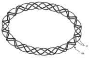
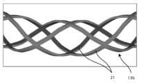
도 7a 및 도 7b는, 길이 방향 범위에서의 증가의 측면 그리고 형상의 변화의 측면 양자 모두에서의 변형을 허용하는 본 발명의 일 실시예에 따른 환형 요소의 코어의 구성의 해법의 일례를 도시한다.
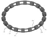
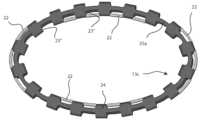
도 8a 및 도 8b는, 또한 길이 방향 범위에서의 증가의 측면 그리고 형상의 변화의 측면 양자 모두에서의 변형을 허용하는 본 발명의 일 실시예에 따른 환형 요소의 코어의 상이한 구성의 해법을 도시한다.
도 9a 및 도 9b는, 메쉬 구조에 강제적으로 삽입되는 생체-침식 재료의 블록들에 의해 환형 요소의 코어의 변형된 구성을 고정하기 위한 기술을 설명한다.
도 10a 및 도 10b는, 길이 방향으로 비-신장성의 기하학적 형상인, 형상의 변경의 측면에서의 변형만을 허용하는, 본 발명의 일 실시예에 따른 환형 요소의 코어의 상이한 구성의 해법을 도시한다.
도 11은, 구조의 일부 개구들에 강제적으로 삽입되는 생체-침식 재료의 블록들에 의해 환형 요소의 코어의 변형된 구성을 고정하기 위한 기술을 설명한다.
도 12a 및 도 12b는, 또한, 길이방향으로의 연장의 측면에서 코어의 변형을 허용하기 위해서 도 10a 및 도 10b에서 설명된 해법과 관련한 변형을 예시하는 본 발명의 일 실시예에 따른 환형 요소의 코어의 상이한 구성의 해법을 도시한다.
도 13a 및 도 13b는, 코어의 구조에 강제적으로 연결되는 생체-침식 재료의 인서트들에 의해 환형 요소의 코어의 변형된 구성을 고정하기 위한 기술을 설명한다.The solution according to one or more embodiments of the present invention, with respect to other features and associated advantages, will be better understood by reference to the following detailed description, which is given entirely by way of non-limiting example. is intended to be read in conjunction with the accompanying drawings, in which, for simplicity, corresponding elements are indicated by the same or similar reference numerals and the description is not repeated. In this regard, the drawings are not necessarily drawn to scale (with some details which may be exaggerated and/or simplified) and, unless otherwise indicated, are merely intended to conceptually illustrate the structures and methods described. It must be clearly understood that it is being used. Especially in the drawings:
1A and 1B show general schematic diagrams of a prosthetic device for the treatment of heart valves, with configurations corresponding to different steps of the implantation method, according to a configuration compatible with embodiments of the invention.
Figures 2A and 2B show in perspective and top views, respectively, two components of the prosthesis illustrated in Figures 1A and 1B.
Figure 2C shows an assembled configuration of the components of Figures 2A and 2B.
3A, 3B, and 3C illustrate the same components of the prosthetic device in both separate and assembled configurations, wherein the annular element with restoration of the correct operational configuration if the cause of deformation is removed. It is assumed that is temporarily deformed in the direction of increasing its circumferential extent in its longitudinal direction.
FIGS. 4A, 4B, and 4C illustrate the same components of the prosthetic device in both separate and assembled configurations, wherein the annular element with restoration of the correct operational configuration if the cause of deformation is removed. It is assumed that is temporarily deformed in the direction of ovalization of the shape.
5A and 5B show another version of the components of the prosthetic device for the treatment of heart valves, which has both a separate and an assembled structure, with a circular geometry and different geometric shapes. All are illustrated in FIGS. 1A and 1B.
FIGS. 6A, 6B, and 6C show the same components of the prosthetic device described in FIGS. 5A, 5B, and 5C in both separate and assembled configurations, once the cause of deformation. It is assumed that if removed, the annular element is temporarily deformed both by increasing its circumferential extent and by changing its shape, with restoration of the correct operational configuration.
7a and 7b show an example of a solution of the configuration of the core of an annular element according to an embodiment of the invention, which allows variations both in terms of an increase in the longitudinal extent and in terms of a change in shape .
8a and 8b also show solutions of different configurations of the core of the annular element according to an embodiment of the invention, which allow variations both in terms of an increase in the longitudinal extent and in terms of a change in shape .
9A and 9B illustrate a technique for fixing a modified configuration of the core of an annular element by blocks of bio-erodable material forcibly inserted into the mesh structure.
10a and 10b show solutions of different configurations of the core of the annular element according to one embodiment of the invention, which allows only deformation in terms of change of shape, which is a non-extensible geometric shape in the longitudinal direction. .
Figure 11 illustrates a technique for fixing a modified configuration of the core of an annular element by blocks of bio-erodable material forcibly inserted into some openings of the structure.
Figures 12a and 12b show a diagram of an annular element according to an embodiment of the invention, also illustrating a variation with respect to the solution described in Figures 10a and 10b to allow for deformation of the core in terms of its longitudinal extension. Solutions of different configurations of the core are shown.
Figures 13a and 13b illustrate a technique for fixing a modified configuration of the core of an annular element by means of inserts of bio-erodable material forcibly connected to the structure of the core.
도 1a 및 도 1b는, 본 발명에 따른 심장 판막용 인공삽입물(10)의 이식 방법의 2 개의 상이한 단계들을 개략적으로 예시하는데, 여기서, 인공삽입물은 치료될 자연 방실 판막(atrio-ventricular valve)(V)의 기능을 대체하기 위해 사용된다. 인공삽입물(10)은 환형 요소(12)의 형태 인 제1 구성요소 및 인공삽입 판막 판막첨(16)을 지지하는 중심 부재(14)의 형태인 제2 구성요소를 포함한다. 이식 방법 중에, 환형 요소(12)는 자연 방실 판막(V)을 완전하게 둘러싸기 위해서 방실 판막(V)의 외측에 위치되는 한편, 중심 부재(14)는 동일한 자연 방실 판막(V) 내측으로 팽창된다(도 1a). 중심 부재(14)의 팽창은, 2 개의 구성요소들(12, 14)이 서로 연결되는 것을 유발한다(도 1b). 2 개의 구성요소들(12, 14) 사이의 접촉은 직접적인 것이 아니라 그 대신에 2 개의 구성요소들(12, 14) 사이에 삽입된 채 유지되는 자연 판막(V)의 판막첨(L)의 개재(interposition)로 발생한다. 자연 방실 판막(V)의 유연성 및 변형성의 결과로서, 인공삽입물(10)의 최종 구성은 2 개의 구성요소들(12, 14) 사이의 상호 작용동안 상호 교환된 힘들의 균형에 의해 주로 결정되며, 2 개의 구성요소들(12, 14) 각각의 탄성 복귀에 따른다. 특히, 환형 요소(12)가 교환된 힘들에 대해서, 원주 방향으로, 즉 길이 방향으로 실질적으로 비-신장성이거나 적어도 부분적으로 강성이라면, 중심 부재(14)는 환형 요소(12)의 내부 원주(12a)의 길이만큼 허용되는 방사상 치수만큼 팽창한다. 구조적 상호작용의 측면에서 자연 판막의 기여가 실질적으로 무시할 수 있기 때문에, 인공삽입물(10)의 최종 평형 상태, 즉 이식후 상태(post-implantation)의 구성은 따라서, 예측 가능하고 제어 가능하다. 도 1a 및 도 1b에서 설명된 선도는, 적적으로 인공삽입물(10)의 기본 작동 원리를 나타내며, 그 구성의 해법의 맥락에서, 상이한 해법들을 제공할 수 있다. 예를 들어, 환형 요소(12)는 자연 방실 판막(V) 둘레에 그의 준비된 위치설정(positioning)을 허용하기 위해서 개방되고 그리고/또는 복수의 부분들로 세분화될 수 있다.1A and 1B schematically illustrate two different steps of the method of implantation of a
환형 요소(12)는, 그 다음에, 중심 부재(14)의 팽창 전에 재-폐쇄 및/또는 재-조립된다. 인공삽입물(10)의 이식 단계 동안 2 개의 구성요소들(12, 14) 사이에서 상호 위치설정을 안정적이며 그리고 미리 정해진 상태로 유지하기 위해서 환형 요소(12)와 중심 부재(14) 사이의 연결을 위한 가요성 아암들이 더 제공될 수 있다. 더욱이, 인공삽입물(10)의 최종 구성은, 예를 들어, 주로 자연 방실 판막(V)과 유사한 일반적인 기하학적 형상을 재현하기 위해 고려되는 구성의 요건들에 따라 원형 또는 타원형 또는 D 자형 개구를 제공할 수 있다.The
도 2a, 도 2b, 및 도 2c는 인공삽입물(10)의 2 개의 주요 구성요소들(12, 14)의 예들을 개략적으로 예시한다. 구성요소들 또는 인공삽입 시스템의 상이한 구성들은, 전체적으로, 본 발명의 적용가능성 및 효율 그리고 본원에서 이하에 설명되는 그의 구성의 해법에 영향을 미치지 않는다. 특히, 도 2a는, 도면의 좌측에, 환형 요소(12)의 사시도 그리고 도면의 우측에, 중심 부재(14)의 사시도를 도시한다. 도 2b는, 중심 부재(14)에 의해 지지되는 인공삽입 판막 판막첨(16)을 명확하게 볼 수 있는 평면도와 동일한 2 개의 구성요소들(12, 14)을 예시한다.2A, 2B, and 2C schematically illustrate examples of the two
도 2b를 참조하면, 환형 요소(12)의 내부 직경(D1)은, 그의 최대 팽창시에, 즉 임의의 외부 구속이 없는 경우에, 중심 부재(14)의 외부 직경(DD)보다 작으며, 2 개의 구성요소들이 기계적으로 함께 연결되는 횡단면에서 측정된다. 환형 요소(12)의 내부 직경(D1) 사이에 존재하는 간섭은 중심 부재(14)의 외부 직경(DD)보다 작아서, 사용시에 중심 부재(14)의 반경 방향 팽창이 환형 요소(12)의 구성된 구속에 대해서 중단되는 것을 유발하고, 2 개의 구성요소들(12, 14) 사이의 모든 접촉 표면에 걸쳐 실질적으로 연속적인 접촉 압력을 생성하여, 이에 따라 그의 연결이 안정적으로 되게 하고 그리고, 이와 동시에 인공삽입물(10)의 기능적으로 안정적인 구성으로 2 개의 구성요소들(12, 14) 사이에 삽입되는 자연 판막첨(V)을 차단한다. 중심 부재(14) 내측에 지지되는 인공삽입 판막 판막첨(16)은, 기능적으로 안정적인 인공삽입물(10)의 구성이 최적의 상호 협응(coaptation)을 갖도록 치수결정된다. 기능적으로 안정적인(즉, 중심 부재(14)가 직경만큼 팽창되는 경우) 인공삽입물(10)의 구성에 있어서, 그리고, 이 구성을 둘러싸는 환형 요소(12)에 의해 발생된 반경 방향 구속에 의해 결정되는 구성들에 있어서, 인공삽입물 판막 판막첨(16)은 도 2c(이는 이식된 인공삽입물(10)의 특성 조립 구성에서 2 개의 구성요소들(12, 14)의 평면도로서 예시함)에서 개략적으로 도시된 바와 같이 임의의 역방향 유동을 제거하기 위해 폐쇄 중에 인공삽입물(10)의 개구를 완전히 밀봉하기 위한 능력을 갖는다.Referring to Figure 2b, the inner diameter D1 of the
메인 부재(14)의 최대 가능한 팽창의 구성에서, 도 2b의 우측에서 볼 수 있는 바와 같이, 인공삽입 판막 판막첨(16)은 무능력하며, 따라서 판막의 폐쇄가 불충분하다. 본 발명의 일 양태에 따르면, 중심 부재(14)는, 인공삽입 판막 판막첨(16) 사이의 협응이 과도 기간에 걸쳐 의도적으로 부분적으로 그리고 어떠한 경우라도 불충분하도록, 도 2c의 기능적으로 안정적인 구성을 위해 제공되는 것과 상이한 기하학적 형상보다 더 크게 그리고/또는 기하학적 형상에 따라 팽창되는 것이 허용된다. 따라서, 인공삽입물(10)은 이들의 일시적인 조건들 하에서 그 작동 중에 영향을 받는데, 이들 일시적인 조건들은 내부-인공삽입물 부전의 정도에 의해, 즉 개구를 통한 역방향 유동에 의해 변형의 전체에 비례하여 기능적으로 안정적인 구성에 대하여 변경되며, 중심 부재(14)는 그 기능적으로 안정적인 구성에 대해, 즉 최적 작동 조건에 대해 변형을 받게 된다.In the configuration of maximum possible expansion of the
도 3a, 도 3b, 및 도 3c는, 환상 요소(12)가 적어도 제한된 기간 동안 내부 직경(D2)을 갖는 인공삽입물(10)을 도시하며, 이 내부 직경(D2)은 기능적으로 안정적인 구성으로 중심 부재(14)를 보유할 수 있는 내부 직경(D1)과, 동일한 완전히 팽창된 중심 부재(14)가 어떠한 외부 구속도 없다는 것으로 가정될 수 있는 외부 직경(DD) 사이에서 치수적으로 중간이다. 도 3b에 예시된 바와 같이, 조립된 인공삽입물(10)은 중심 부재(14)의 팽창부를 가지며, 중심 부재(14)는 중심 부재 둘레에 감겨지는 환형 요소(12)에 의해 제한되는데, 2 개의 구성요소들(12, 14)은 도 2c에서와 같은 기능적으로 안정적인 구성중 최적의 구성보다 더 큰 평형 상태 직경으로 서로 연결된다. 결과적으로, 인공삽입 판막 판막첨(16) 사이의 폐쇄 동안의 협응은, 또한 불충분하며(도 3b), 중심 역류 개구(R)는 판막이 폐쇄된 상태로 틈새(aperture) 내측에 남아 있게 된다. 2 개의 구성요소들(12, 14) 사이의 최적의 연결에 의해 제공되는 것보다 큰 원주 방향 범위로의 환형 요소(12)의 사전-팽창은, 인공삽입물(10)의 측면에서 역류(inverse flow)로 인한 밀봉 용량의 손실을 결정하며, 이는 따라서 무능력하다. 환형 요소(12)의 변형이 영구적이었다면, 인공삽입물(10)은 그의 생체내(in-vivo) 작동의 관점에서 안정적으로 무능력할 것이다. 그러나, 환형 요소(12)가 유사한 과도 기간에 걸쳐 시간 경과에 따라 그의 길이 방향 연신(elongation)을 점진적으로 회복할 수 있다면, 역류는, 또한, 제거되는 한 감소하는 경향이 있을 것이다. 이 과도 기간의 종료시, 판막 인공삽입물(10)은 도 3c에서 예시된 바와 같이, 기능적으로 안정적인 그의 최적의 구성에 따라 그의 생체내 작동 중에 역류에 대한 완전한 능력을 획득할 것이다.3A, 3B and 3C show a
도 4a, 도 4b, 및 도 4c는, 환상 요소(12)가 적어도 제한된 기간동안 이식된 인공 삽입물(10)의 기능적으로 안정적인 적절한 작동을 위해 제공되는 것과 상이한 기하학적 형상을 취하는 인공삽입물(10)을 예시한다. 도 4a에서 제시된 예들은, 본 발명의 일반적인 특성의 단순한 비제한적인 설명 목적과 함께, 보다 작은 직경(D3) 및 더 큰 직경(D4)을 갖는 타원형 기하학적 형상으로 변형되는 환형 요소(12)를 도시한다. 일반적으로, 환형 요소(12)의 내부 원주(12a)는 도 2a 및 도 2b의 직경(D1)의 원주와 등가인 길이를 갖는다. 환언하면, 도 4a에 도시된 환형 요소(12)는 도 2a 및 도 2b에 도시된 환형 요소(12)의 타원화에 의해 실질적으로 얻어진다. 일반적으로, 또한, 하기에서 도시되는 바와 같이 타원 형상과 상이한 변형을 부과할 수 있다. 환형 요소(12)의 변형의 결과는 도 4b에 개략적으로 도시되어 있으며, 여기서, 인공삽입물(10)의 이식된 구성을 나타내는 조립된 시스템은, 또한, 인공삽입 판막 판막첨(16)의 결과적인 뒤틀림 및 폐쇄 동안의 협응의 손실을 갖는 중심 부재(14)의 타원화를 도시한다. 따라서, 환형 요소(12)의 형상의 관점에서의 변형은, 인공삽입물(10)의 2 개의 구성요소들(12, 14) 사이의 단단한 연결을 허용하지만, 이와 동시에, 내부-인공삽입물 역류의 출현과 함께 무능력한 폐쇄를 초래하지는 않는다. 이 경우에도 또한, 형상의 변형이 일시적이라면, 즉, 환형 요소(12)가 그의 기능적으로 정확한 형상을 시간의 경과에 따라 회복할 수 있다면, 인공삽입물(10) 전체는 또한, 도 4c에 표시된 바와 같이, 과도 기간의 종료시에 완전히 능력있는 인공삽입 판막 판막첨(16)의 적절한 폐쇄를 점진적으로 회복할 것이다.4A, 4B and 4C show a
도 3a 및 도 4a를 참조하여 상기 설명된 환형 요소(12)의 길이 및 형상의 변경은 또한 동시에 적용될 수 있으며, 환형 요소(12)의 원주 방향 범위의 증가 및 그의 형상의 관점에서의 변경의 조합을 초래한다. 상기 설명된 기술들에 따라 일시적이고 가역적인 변형들의 이러한 조합을 통해, 정확한 제한 효과, 즉, 이식 단계 동안 환형 엘리먼트(12)가 연결되는 자연 병리학적 방실 판막(V)의 팽창된 환체의 인버스 리모델링의 정확한 제한 효과, 그리고 인공삽입물(10)의 일시적인 무능력 효과(이는, 유리하게는, 인공삽입물(10)이 이식된 직후에 심실 근육에 의해 겪게되는 혈역학적(haemodynamic) 부하의 위험한 급격한 증가를 방지하는 것을 허용함)가 동시에 얻어진다.The changes in the length and shape of the
앞선 도면들에 제시된 예들은 전적으로 예시적인 것이며, 본 발명에 의해 채택될 수 있는 가능한 구성의 해법들의 관점에서 제한하려는 것은 아니다. 예시로서, 도 5a 및 도 5b는, 본 발명에 따른 인공삽입물(10)의 상이하고 그리고 보다 일반적인 구성의 해법을 도시한다. 도 5a는, 환형 요소(12) 및 중심 부재(14)가 서로 상이하고 양자 모두가 반드시 원형일 필요는 없는 기하학적 형상들을 가질 수 있는 방법을 제시하는 2 개의 개별 구성요소들(12, 14)의 평면도이다. 환형 요소(12)는, 도 5a의 좌측에 예시된 바와 같이, 내부-심실 판막(V)의 환체의 해부학적 형상과 매우 유사한 실질적으로 "D"자 형상을 가질 수 있으며, 따라서 이식 방법 중에 내부-심실 판막의 환체에 연결하는데 특히 적합하다. 중심 부재(14)는 그 대신에, 최종 조립된 구성에서 정확한 협응을 발생시키도록 최적화된 인공삽입 판막 판막첨(16)의 비대칭 구성을 갖는 일반적인 타원 형상을 가질 수 있다. 도 5b는, 환형 요소(12) 내측에서 초기에 붕괴되는 중심 본체(14)의 팽창에 후속하여 2 개의 구성요소들 사이에 도달되는 탄성 평형 상태로부터의 결과들로서, 인공삽입물(10)의 조립된 구성을 도시한다. 이러한 평형의 구성이 인공삽입물(10)의 설계 단계 동안 실질적으로 판정되므로, 자연 판막(V)의 장치의 효과가 최소가 되기 때문에, 이 인공삽입 판막첨이 완전히 능력이 있으며, 즉, 도 5b에서 예시된 이식되고 기능적으로 안정적인 구성으로, 폐쇄 동안 임의의 내부-인공삽입 개구없이, 인공삽입물이 완전히 능력이 있도록 인공삽입 판막첨(16)의 시스템을 구성하는 것이 또한, 가능하다.The examples presented in the foregoing drawings are purely illustrative and are not intended to be limiting in terms of the possible configuration solutions that may be employed by the present invention. By way of example, Figures 5a and 5b show different and more general configuration solutions of the
도 6a, 도 6b, 및 도 6c는 본 발명의 상이한 실시예를 도시한다. 도 6a는 인공삽입물(10)의 개별 구성요소들(12, 14)을 예시한다. 환형 요소(12)는 치수들의 관점에서(즉, 더 큰 원주방향 범위) 그리고 환형이 되는 형상의 관점 양자 모두에서 변형된다. 도 6b는, 인공삽입물의 정확한 작동과 관련된 안정적인 구성으로부터 치수와 형상의 관점에서 상이한, 조립된 인공삽입물(10)의 최종 구성으로 환형 요소(12) 상에 부과되는 변형의 효과를 도시한다. 인공삽입물 판막 판막첨(leaflets)(16) 사이의 협응의 결여의 결과로서 틈새에서 발생되는 개구(R)는, 내부-인공삽입물 역방향 유동을 일으켜 인공삽입물(10)을 무능력하게 만든다. 환형 요소(12)에 적용된 변형이 상기 설명된 본 발명의 원리들에 따라, 일시적이고 가역적이라면, 변형된 구성의 고정 구성요소의 생체-침식의 속도에 의해 결정되는 과도 시간 주기를 갖는 상태에서, 인공삽입물(10)은 보다 작은 반경방향 치수들 그리고 인공삽입물 판막 판막첨(16) 사이의 정확한 협응을 갖는 정상 작동을 위해 그의 안정적인 구성을 회복한다. 따라서, 이 경우에, 인공삽입물(10)은 자연 방실 판막(V)의 환체의 수축 및 리모델링의 발생, 그리고 심실이 겪는 혈역학적 부하를 점진적으로 증가시킴으로써 판막 부전의 점진적인 제거 양자 모두가 또한 가능할 수 있다.Figures 6a, 6b, and 6c show different embodiments of the invention. Figure 6A illustrates the
도 7a 및 도 7b는, 도면의 보다 양호한 이해를 위해서, 본 발명의 일 실시예에 따른 환상 요소의 코어의 가능한 하나의 기하학적 형상의 개략도인 2 개의 상이한 사시도들에 따라 도시한다. 코어는 실질적으로 3 차원 나선 형상으로 발생된다. 유사한 기하학적 형상은 금속 실을 사용하여 얻어질 수 있는데, 이는 구조의 보다 큰 안정성을 위해 또는 폐쇄된 도면을 형성하도록 곡선 튜브에 기초하여 미리 형성되고 그리고 선택적으로 그의 단부에 연결되며, 선택적으로 상호 용접된 헤드 단부들을 가지며, 그리고, 여기서, 나선형 기하학적 형상은 적절한 방식으로, 예를 들어, 레이저 절단에 의해 벽을 절단함으로써 발생된다. 코어를 구성하는 재료는, 일반적으로, 금속 또는 금속 합금, 예를 들어 티타늄 합금일 수 있다. 특히, 인간의 경피적카테터 기술 분야의 디바이스들에 대해, 그의 초-탄성 특성의 결과로서 니티놀(Nitinol)로 상업적으로 공지된 니켈/티타늄 합금이 유리하게 사용되는데, 이는 큰 변형들을 허용하면서 재료의 복원력의 일정 범위뿐만 아니라 그의 생체적합성을 유지한다. 축 방향 신장성과 굴곡 변형성의 결과로서, 도 7에 도시된 구조는 팽창(즉, 축 방향 길이의 증가)의 관점 그리고 형상의 수정의 관점 양자 모두에서 일시적으로 변형될 수 있으며, 유리하게는, 상기에서 이미 설명된 기술에 따른 생체-흡수성 또는 생체-침식 재료를 인접한 헬릭스들 사이의 공동에 충전한다.7a and 7b show in two different perspective views a schematic diagram of one possible geometric shape of the core of a toroidal element according to an embodiment of the invention, for a better understanding of the drawings. The core is formed into a substantially three-dimensional helical shape. Similar geometric shapes can be obtained using metal threads, which are preformed for greater stability of the structure or on the basis of curved tubes to form a closed figure and optionally connected to their ends, optionally welded together. has head ends, where the spiral geometry is created by cutting the wall in a suitable manner, for example by laser cutting. The material making up the core may generally be a metal or metal alloy, for example a titanium alloy. In particular, for devices in the field of human percutaneous catheter technology, a nickel/titanium alloy, commercially known as Nitinol, is advantageously used as a result of its super-elastic properties, which allow large deformations while maintaining the resilience of the material. maintains its biocompatibility as well as a certain range of . As a result of the axial stretchability and flexural deformability, the structure shown in Figure 7 can be temporarily deformed both in terms of expansion (i.e. increase in axial length) and in terms of modification of shape, advantageously comprising: The cavities between adjacent helices are filled with a bio-absorbable or bio-erodible material according to the technology already described.
도 8a 및 도 8b는, 본 발명의 상이한 실시 예에 따른 환형 요소의 코어의 다른 버전을 예시한다. 도 8a는 코어 전체를 도시하는 한편, 도 8b는 그의 일 부분의 상세를 도시한다. 본원에 도시된 구조의 해법에서, 코어는 메쉬형 토로이달(meshed toroidal) 구조에 의해 실질적으로 구성된다. 이 경우에, 구조는 또한, 금속실들의 직물(fabric of interwoven metal threads)에 의해 그리고 링을 형성하도록 굴곡된 튜브로부터 시작하는 것 양자 모두에 의해 의해 구성될 수 있으며, 이 링은 선택적으로는, 반드시 폐쇄되는 것은 아니며, 그의 벽 상에서, 레이저 절단에 의해 적당한 개구들이 발생된다. 이 마지막 방법이 특히 유리하여, 메쉬의 아암들의 두께뿐만 아니라 튜브형 요소의 벽에 형성된 다양한 개구들의 치수들, 형상, 및 위치의 원하는 변경을 허용한다. 이런 식으로, 프로젝트의 요건들에 따라 코어 및 그에 따른 환형 요소의 탄성 복귀를 자유롭게 조정하기 위해서 큰 자유도의 구성이 제공된다. 단순히, 예시로서, 코어의 탄성 복귀는 위치에 따라 변화될 수 있으며, 더 경질인 영역들 및 보다 가요적인 영역들을 구성하는 것이 가능하거나, 전체적으로 그리고 단지 국부적 양자 모두로 구조의 이방성 거동을 얻을 수 있으며, 이는 예를 들어, 평면 내측의 변형들에 대해서는 가요성 코어를 제공하지만 평면 외측의 변형들에 대해서는 극도로 강성인 것을 제공할 수 있다.Figures 8a and 8b illustrate different versions of the core of the annular element according to different embodiments of the invention. Figure 8a shows the core as a whole, while Figure 8b shows details of a portion thereof. In the structural solution shown here, the core is substantially constructed by a meshed toroidal structure. In this case, the structure can also be constructed both by a fabric of interwoven metal threads and by starting from a tube bent to form a ring, which optionally consists of: It is not necessarily closed; suitable openings are created on its walls by laser cutting. This last method is particularly advantageous, allowing the desired variation of the dimensions, shape and location of the various openings formed in the wall of the tubular element as well as the thickness of the arms of the mesh. In this way, a large freedom of configuration is provided in order to freely adjust the elastic return of the core and thus the annular elements depending on the requirements of the project. Simply by way of example, the elastic return of the core can be varied depending on the position, making it possible to construct stiffer regions and more flexible regions, or to obtain an anisotropic behavior of the structure both globally and only locally. , which may, for example, provide a flexible core against in-plane deformations but extremely rigid against out-of-plane deformations.
사용될 수 있는 재료들은, 분명히, 상기 설명된 구성의 해법과 동일하다.The materials that can be used are obviously identical to the structural solutions described above.
상기에 수여된 탄성 특성들에 독립적으로, 도 8에 설명된 메시형 구조는 도 7의 구조와 유사하게 그의 축 방향 범위가 증가하고, 초기 형상에 대해 상이한 형상들에 따라 변형되고 그리고 양자 모두의 변형들이 겹쳐지는 가능성을 허용한다.Independently of the elastic properties imparted above, the mesh-like structure described in Figure 8, similar to the structure in Figure 7, increases in its axial extent, deforms according to different shapes with respect to the initial shape and both Allows for the possibility of overlapping transformations.
본 발명의 일 실시예에 따르면, 변형된 구성은 적절하게 변형된 코어 위의 생체-침식 또는 생분해성 재료의 공동-성형, 예를 들어 주형 내에서의 공동-성형에 의해 미리 정해진 시간동안 고정될 수 있어, 코어의 구조에 대한 왜곡 효과를 유지하는 커버링을 발생시킨다. 달성하고자하는 특정 변형, 또는 변형된 구성을 포함하여 코어에서 보존하는 것이 바람직한 탄성 특성들에 따라, 공동-성형은 코어의 모든 부분 또는 코어의 제한된 일 부분들만을 포함할 수 있다.According to one embodiment of the invention, the modified configuration may be fixed for a predetermined period of time by co-molding of a bio-erodable or biodegradable material on an appropriately modified core, for example by co-molding within a mold. This creates a covering that maintains the distorting effect on the structure of the core. Depending on the particular strain desired to be achieved, or the elastic properties desired to be preserved in the core, including the strained configuration, co-molding may involve all portions of the core or only limited portions of the core.
도 9a 및 도 9b에 예시된 또 다른 구조 방법은, 적절하게 형상화되고 치수가 정해지고 그리고 메쉬에 존재하는 개구에 강제적으로 삽입되는 생체-침식 재료의 웨지들 또는 블록들과 같은 인서트들의 사용을 제공한다. 특히, 도 9a는 도 8에 설명된 코어의 구조의 비-변형 부분(non-deformed portion)을 다음 도면에 대한 참조로서 도시한다. 도 9b는 본 발명의 일반적인 특성의 비 제한적 예로서, 적절히 과도하게 치수가 정해지는 생체-침식 재료의 블록들이 도 9a의 구조의 메시의 개구들 내측에 강제로 끼워지면 변형된 구성을 고정할 수 있는 방법을 도시한다. 메쉬의 개구들이 서로 상이한 치수들을 갖는 보다 일반적인 경우를 가정하면, 강제되는 내부 개구의 치수들에 따라 각각의 블록의 과잉 치수결정 기준이 전체 구조에 걸쳐 일정하게 유지된다면, 얻어지는 효과는 그의 동조적(homothetic) 팽창이다. 환언하면, 블록과 개구 사이의 간섭의 백분율이 구조 상의 위치와 독립적으로 일정하게 유지된다면, 도 9b에 나타낸 바와 같이, 그의 형상의 실질적인 변형없이 구조의 축 방향 범위를 증가시키는 효과가 일반적으로 얻어진다. 그러나, 간섭의 백분율이 위치에 따라 변한다면, 링의 형상의 변경이 또한 얻어진다. 예를 들어, 간섭의 백분율이 외부 면에서의 개구들에 비해 내부 면의 개구들에 대해 더 크다면, 구조의 축의 곡률 반경이 증가한다(직선화(straightening) 효과). 다른 한편으로, 간섭의 백분율이 외부 면의 개구들에 대해 더 크다면, 축의 곡률 반경이 감소한다(구부림(bending) 효과). 응용 예의 예로서, 2 개의 정반대 부분들(diametrically opposed portions)에 직선화 효과(내부 면에서 간섭의 백분율이 더 큼) 및 직전과 또한 직교하는 2 개의 정반대 부분들에 대한 구부림 효과(외부 면에서 간섭의 백분율이 더 큼)를 적용함으로써, 초기에 원형인 코어의 타원화(ovalization) 또는 특정 경우에, 초기에 타원형인 코어의 원형화(circularization)가 얻어지는 것이 명백하다. 또한, 그의 축방향 범위를 증가시키지 않고 코어의 기하학적 형상의 변형만을 얻는 것이 가능하고, 양쪽 모두가 아닌 구조의 단일 면에서 블록들의 삽입에 의해 직선화 효과 또는 구부림 효과를 발생시키는 것이 명백하다.Another construction method, illustrated in FIGS. 9A and 9B , provides for the use of inserts such as wedges or blocks of bio-erodible material that are suitably shaped and dimensioned and forcefully inserted into openings present in the mesh. do. In particular, FIG. 9A shows a non-deformed portion of the structure of the core illustrated in FIG. 8 with reference to the following figures. FIG. 9B is a non-limiting example of the general nature of the invention, in which appropriately oversized blocks of bio-erodible material can be forced inside the openings of the mesh of the structure of FIG. 9A to secure the deformed configuration. Shows how. Assuming the more general case where the openings of the mesh have different dimensions, if the over-dimension criterion of each block is kept constant throughout the entire structure according to the dimensions of the forced internal openings, the effect obtained is its homogeneous ( homothetic expansion. In other words, if the percentage of interference between blocks and apertures is kept constant independent of their position on the structure, the effect of increasing the axial range of the structure is generally achieved without substantial modification of its shape, as shown in Figure 9b. . However, if the percentage of interference varies with location, a change in the shape of the ring is also obtained. For example, if the percentage of interference is greater for openings on the inner face compared to openings on the outer face, the radius of curvature of the axis of the structure increases (straightening effect). On the other hand, if the percentage of interference is larger for the openings of the outer face, the radius of curvature of the axis decreases (bending effect). As an example of an application example, a straightening effect on two diametrically opposed portions (the percentage of interference is greater on the inner side) and a bending effect on two diametrically opposite portions that are also orthogonal (the percentage of interference on the outer side is greater). It is clear that by applying the percentage (the larger the percentage), an ovalization of the initially circular core or, in certain cases, a circularization of the initially oval core is obtained. It is also clear that it is possible to obtain only a variation of the geometry of the core without increasing its axial extent, and to produce either a straightening effect or a bending effect by the insertion of blocks on a single side of the structure and not both.
도 8에 예시된 것과 유사한 메시형 코어 내의 개구들의 가능한 위치들의 다양성에 비추어, 적절하게 형상화되고 치수 결정되는 생체-침식 재료의 블럭들 또는 웨지들의 강제 삽입에 의해 얻어질 수 있는 구조의 변형들의 범위가 얼마나 광범위하고 다양한지가 즉각적으로 이해될 수 있다. 탄성 범위에 변형이 부과되면, 선택적으로 Nitinol과 같은 초-탄성 합금들을 선택적으로 사용하면, 블록들을 발생시키는 재료의 인간 생리학 분야에서 일어나는 열화(degradation)는 시간이 지남에 따라 왜곡 효과의 소멸 및 코어 그리고 이에 따라 환형 요소의 원래의 기하학적 특성 및 기계적 특성의 회복으로 이어진다.In light of the variety of possible positions of openings in a mesh-like core similar to that illustrated in Figure 8, the range of structural modifications that can be achieved by forced insertion of appropriately shaped and dimensioned blocks or wedges of bio-erodible material. It is immediately apparent how broad and diverse it is. When strain is imposed on the elastic range, optionally using super-elastic alloys such as Nitinol, the degradation that occurs in the field of human physiology of the material from which the blocks are generated will lead to the disappearance of the distortion effect over time and the core This leads to restoration of the original geometric and mechanical properties of the annular element.
도 10a 및 도 10b는, 본 발명의 상이한 실시예에 따른 환형 요소의 코어의 다른 버전을 도시한다. 구조의 구성을 보다 명료하게 하기 위해 도 10a에서 전체적으로 그리고 도 10b에서 상세히 예시된 구조는 도 7 및 도 8에 도시된 것과 기능의 관점에서 상이한데, 이는 길이 방향으로 실질적으로 불가능하지만 단지 기하학적으로 변형 가능하기 때문이다. 실제로, 튜브의 벽에서 이러한 구성으로 또한 형성되고 이를 가요적으로 만드는 다수의 개구들에도 불구하고, 구조의 다양한 하부-요소들을 연결하는 적어도 하나의 연속적인 링의 존재는 구조물이 축 방향 범위의 관점에서 연장할 수 없게 한다. 단일의 연속 링 구조의 존재는 3 차원 공간에서 코어의 변형들을 허용한다. 그러나, 도 10에 도시된 바와 같이 상부 면 및 하부 면 상에 직경 방향으로 위치되거나 보다 일반적으로 축 방향으로 서로 이격된 2 개의 링의 존재는, 평면에서의 구조의 변형도(degree of deformability)를 제한한다. 따라서, 환형 요소의 절대적인 비-신장성(absolute non-extensibility)이 이식된 인공삽입 시스템의 정상 동작 모드 중에 요구되는 경우에 필요할 수 있는 이러한 구성의 해법은 변형되었지만 팽창되지 않은 구성을 허용한다. 기하학적 변형은, 생체-침식 재료의 커버링 내부에서 코어 또는 그의 단지 일부분을 둘러싸는 방식으로 또는 적합한 스페이서들 또는 블록들(이들은 동일한 생체-침식 재료로 발생되고 그리고 구조의 개구들 내측에 강제됨)의 삽입에 의해, 일시적으로 고정될 수 있다. 예로서, 본 발명의 일반적인 특성을 제한하려 하지 않으면서, 도 11은 구조의 일부 특정 개구들(이들은 구조의 축의 국부적인 곡률 반경에 대한 바람직한 수정에 따라 선택됨)에 생체-침식 재료의 블록들을 강제 삽입함으로써 도 10에 설명된 구조에 부과된, 원형으로부터 타원형으로의 형상의 변경을 도시한다.10a and 10b show different versions of the core of the annular element according to different embodiments of the invention. In order to make the configuration of the structure more clear, the structure illustrated as a whole in Figure 10a and in detail in Figure 10b differs in terms of functionality from that shown in Figures 7 and 8, which is not substantially possible in the longitudinal direction, but only geometrically deformed. Because it is possible. In fact, despite the large number of openings also formed in this configuration in the wall of the tube and making it flexible, the presence of at least one continuous ring connecting the various sub-elements of the structure ensures that the structure is flexible in terms of axial extent. It cannot be extended. The presence of a single continuous ring structure allows for deformations of the core in three-dimensional space. However, the presence of two rings located diametrically or more generally axially spaced apart from each other on the upper and lower faces, as shown in Figure 10, increases the degree of deformability of the structure in the plane. limit. Therefore, this configuration solution allows for a deformed but non-expanded configuration, which may be necessary in cases where absolute non-extensibility of the annular element is required during the normal operating mode of the implanted prosthetic system. Geometrical modifications can be made by enclosing the core or only a part thereof within a covering of bio-erodible material or by means of suitable spacers or blocks (which are made of the same bio-erodible material and are forced inside the openings of the structure). By insertion, it can be temporarily fixed. By way of example, and without intending to limit the general nature of the invention, Figure 11 illustrates forcing blocks of bio-erodible material into some specific openings of the structure (which are selected according to the desired modification to the local radius of curvature of the axis of the structure). The inset shows the change in shape from circular to oval imposed on the structure illustrated in Figure 10.
도 12a 및 도 12b는 도 10에서 설명된 환형 요소의 코어의 구성의 변경을 도시하는데, 이는 또한 길이 방향으로 구조를 변형시킬 수 있는 가능성을 다시 도입하여 그의 원주 방향 범위를 증가시키고 게다가 그의 형상을 변경시킨다. 일반적으로, 도 10의 구성을 특징짓는 링들의 구성 부분들로서 변형 가능하고 그리고 신장 가능한 요소들의 도입은, 또한 축 방향으로의 그의 연장을 허용한다. 도 12에 설명된 구조의 해법에서, 도 12b에서 명확하게 예시된 바와 같이, "S"자 형상 요소들의 도입은 코어의 원주방향 범위를 증가시키기 위한 방향으로의 팽창 가능성에 의해 주어진 추가 자유도를 도입한다.Figures 12a and 12b show a change in the configuration of the core of the annular element described in Figure 10, which also reintroduces the possibility of deforming the structure in the longitudinal direction, increasing its circumferential extent and, moreover, changing its shape. change it In general, the introduction of deformable and stretchable elements as constituent parts of the rings characterizing the configuration of FIG. 10 also allows its extension in the axial direction. In the solution of the structure described in Figure 12, the introduction of "S" shaped elements, as clearly illustrated in Figure 12b, introduces an additional degree of freedom given by the possibility of expansion in the direction to increase the circumferential extent of the core. do.
도 12에 설명된 구조의 해법의 경우에, 변형된 구성은 또한 코어의 일부 적절하게 선택된 부분들에서만 생체-침식 재료를 공동-성형(co-molding)함으로써 또는 동일한 생체-침식 재료로 제조되고 초기 토로이달 구조의 벽에 형성된 개구들 내측에 적절하게 치수가 정해지고 그리고 강제로 도입되는 블록들 및 웨지(wedges)에 의해 일시적으로 고정될 수 있다. 게다가, 도 12의 구조의 해법은 단지 "S"와 같은 연결의 기하학적 형상으로 생체-침식 재료를 간섭함으로써 임의의 변형된 구성을 또한 차단할 수 있다. 본 발명의 일반적 특성의 비제한적인 구조의 해법의 예로서, 도 13a 및 도 13b는, 보다 명확한 설명을 위한 상이한 관점에 따라, 구조물의 다양한 하부 요소들을 연결하는 "S"와 같은 부분의 아암들 사이에 강제 방식으로 매립될 수 있도록 치수결정되고 이격되어, 그 기하학적 형상을 적절하게 변형시키는 핀들이 제공된 생체-침식 재료의 인서트들을 도시한다. 블록에 의해 초래된 기하학적 형상의 수정은, 간격의 증가가 "S"와 같은 부분의 단부들 사이에서 발생되는 경우의 팽창의 구성요소 그리고 그 부분의 등가의 곡률 반경의 변경이 강제되는 경우의 수정의 구성요소 양자 모두를 가질 수 있다. 따라서, 제1 작용은 구조의 전체 원주방향 범위를 증가시키는 효과를 갖는 한편, 제 2 작용은 그의 형상을 수정하는 효과를 갖는다. 이 마지막 양태와 관련하여, "S"와 같은 형상의 반대-대칭은, 어느 아암들의 쌍이 더 큰 범위로 이격되는지에 따라 등가의 곡률 반경의 증가와 감소 양자 모두를 허용한다는 점이 강조되어야 한다. 원주방향 범위 증가의 효과 및 형상의 왜곡 효과를 증가시키는 효과는, 각각 하나의 전체가 다른 하나의 전체에 자율적이고 그리고 비-상관 방식으로 부과될 수 있다는 의미에서 실질적으로 서로 독립적이다.In the case of the solution of the structure described in Figure 12, the modified configuration can also be fabricated by co-molding the bio-eroding material only in some suitably selected parts of the core or from the same bio-eroding material and It can be temporarily secured by blocks and wedges that are appropriately dimensioned and forcibly introduced inside openings formed in the walls of the toroidal structure. Moreover, the solution of the structure of Figure 12 can also block any modified configuration by interfering with the bio-erodible material only with the geometry of the connection, such as an “S”. As an example of a non-limiting structural solution of the general nature of the invention, Figures 13a and 13b show, according to different perspectives for clearer illustration, arms of the "S"-like portion connecting the various lower elements of the structure. It shows inserts of bio-erodible material provided with pins that suitably modify their geometry, sized and spaced so that they can be embedded in a forced manner therebetween. The modification of the geometric shape brought about by the block is a component of expansion in cases where an increase in the spacing occurs between the ends of a section such as "S" and a modification in cases where a change in the equivalent radius of curvature of that section is forced. It can have both components. Thus, the first action has the effect of increasing the overall circumferential extent of the structure, while the second action has the effect of modifying its shape. With regard to this last aspect, it should be emphasized that the anti-symmetry of a shape like the "S" allows both an increase and a decrease in the equivalent radius of curvature, depending on which pair of arms is spaced to a greater extent. The effect of increasing the circumferential extent and the effect of increasing the shape distortion effect are substantially independent of each other in the sense that each one whole can be imposed on the other whole in an autonomous and non-correlated manner.
마지막으로, 경피적카테터 기술의 맥락에서, 이 마지막 구조 해법은 핀들이 편측성(unilateral) 유형의 국부적 구속을 생성하기 때문에, 그 결과로서, 예를 들어, 구성요소의 프로파일을 릴리스 카테터(release catheter) 상의 조립체와 양립시키기 위한 구조물의 부가적인 변형들이 인서트들의 존재시에도 가능하다는 것이 특히 유리한 것으로 나타난다.Finally, in the context of percutaneous catheter technology, this last structural solution is important because the pins create a local constraint of a unilateral type, and as a result, for example, the profile of the component on the release catheter. It appears particularly advantageous that additional modifications of the structure to make it compatible with the assembly are possible even in the presence of inserts.
물론, 동일하게 유지되는 본 발명의 원리, 실시예의 형태들, 및 구조의 상세들은 본 발명의 범위를 벗어나지 않고 설명되고 예시된 것에 대해 광범위하게 변경될 수 있다.Of course, the principles, embodiments, and structural details of the invention may be varied widely with respect to what is described and illustrated without departing from the scope of the invention while remaining the same.
Claims (18)
Translated fromKorean상기 심장 판막용 인공삽입물의 이식 후에 심장 판막의 자연 판막첨들(native leaflets)을 기능적으로 대체하기 위한 인공삽입 판막첨들(prosthetic leaflets);
인공삽입 부재 상에 인공삽입 판막첨들이 장착되는, 상기 인공삽입 부재; 및
상기 심장 판막용 인공삽입물의 이식 후에 점진적으로 용해되도록 제공되는 보유 부재들(retention members)을 포함하고,
상기 인공삽입 부재는 상기 보유 부재들에 의해 변경된 일시적인 기능적 구성으로 고정되고, 그리고 사용 중에, 상기 보유 부재들의 점진적 용해의 효과에 의해, 상기 변경된 일시적인 기능적 구성으로부터 안정적인 미리 정해진 기능적 구성으로 점진적으로 전환되고,
상기 안정적인 미리 정해진 기능적 구성에서, 상기 인공삽입 부재 및 인공삽입 판막첨들은 자연 심장 판막을 생리적으로 대체하고, 그리고 상기 변경된 일시적인 기능적 구성에서, 상기 인공삽입 부재는 상기 안정적인 미리 정해진 기능적 구성에 비해 변형된 형상 및 확장된 치수 중의 한 가지 이상을 가져서, 내부-인공삽입물 역류를 유발하는,
심장 판막용 인공삽입물.As a prosthesis for a cardiac valve,
Prosthetic leaflets for functionally replacing native leaflets of a heart valve after implantation of the prosthesis for the heart valve;
a prosthetic member having prosthetic valve tips mounted on the prosthetic member; and
comprising retention members provided to gradually dissolve after implantation of the heart valve prosthesis,
the prosthetic member is held in a changed temporary functional configuration by the retention members and, during use, gradually switches from the altered temporary functional configuration to a stable predetermined functional configuration by the effect of gradual dissolution of the retention members; ,
In the stable predetermined functional configuration, the prosthetic member and prosthetic valve tips physiologically replace a natural heart valve, and in the altered temporary functional configuration, the prosthetic member is modified relative to the stable predetermined functional configuration. Having one or more of the following shapes and enlarged dimensions, causing endo-prosthetic reflux,
Prosthesis for heart valve.
상기 변경된 일시적인 기능적 구성으로부터 상기 안정적인 미리 정해진 기능적 구성으로의 인공삽입 부재의 점진적인 전환은, 탄성 복귀(resilient return)에 의해 발생하는,
심장 판막용 인공삽입물.According to claim 1,
The gradual transition of the prosthetic member from the altered temporary functional configuration to the stable predetermined functional configuration occurs by resilient return.
Prosthesis for heart valve.
상기 보유 부재들은 생체-침식(bio-erodible) 또는 생분해성(biodegradable) 재료인,
심장 판막용 인공삽입물.According to claim 1,
The retaining members are bio-erodible or biodegradable material,
Prosthesis for heart valve.
상기 인공삽입 부재는 상기 입공삽입 판막첨들을 위한 지지 부재, 및 환형의 둘레 맞닿음 부재를 포함하며, 상기 환형의 둘레 맞닿음 부재는 상기 지지 부재를 둘러싸도록 적응되며, 그리고 상기 환형의 둘레 맞닿음 부재에 대해, 상기 지지 부재는, 사용하는 동안, 상기 지지 부재와 상기 환형의 둘레 맞닿음 부재 사이에 위치하는 상기 심장 판막의 자연 판막첨들을 포획하도록, 반경 방향의 힘으로 팽창할 수 있는,
심장 판막용 인공삽입물.According to claim 1 or 2,
The prosthetic member includes a support member for the orthoprosthetic valve tips, and an annular peripheral abutment member, the annular circumferential abutment member adapted to surround the support member, and the annular peripheral abutment member. For a member, the support member is capable of expanding with a radial force, during use, to capture the natural valve tips of the heart valve located between the support member and the annular circumferential abutment member.
Prosthesis for heart valve.
상기 환형의 둘레 맞닿음 부재는 변경된 일시적인 구성으로부터 안정적인 미리 정해진 구성으로 전환되고, 그리고 상기 환형의 둘레 맞닿음 부재는, 상기 인공삽입 부재의 대응하는 구성들, 변경된 일시적인 기능적 구성, 및 안정적인 미리 정해진 기능적 구성 각각을 전체적으로 규정하도록, 상기 환형의 둘레 맞닿음 부재와 함께 상기 인공삽입 판막첨들의 상기 지지 부재를 동반하도록, 제공되는,
심장 판막용 인공삽입물.According to clause 5,
The annular circumferential abutting member transitions from a modified temporary configuration to a stable predetermined configuration, and the annular circumferential abutting member transitions from the corresponding configurations of the prosthetic member to a changed temporary functional configuration and a stable predetermined functional configuration. provided to accompany the support members of the prosthetic valve tips together with the annular circumferential abutment member to define each of the components as a whole.
Prosthesis for heart valve.
상기 변경된 일시적인 구성의 환형의 둘레 맞닿음 부재는, 상기 안정적인 미리 정해진 구성에 대해 탄성 변형되거나, 확장되거나, 탄성 변형되고 확장되는,
심장 판막용 인공삽입물.According to clause 6,
wherein the annular peripheral abutting member of the modified temporary configuration is elastically deformed, expanded, or elastically deformed and expanded relative to the stable predetermined configuration.
Prosthesis for heart valve.
상기 변경된 일시적인 구성의 환형의 둘레 맞닿음 부재는, 상기 안정적인 미리 정해진 구성에 대해 탄성 변형되거나, 확장되거나, 또는 탄성 변형되고 확장되고,
상기 환형의 둘레 맞닿음 부재는 상기 보유 부재들에 의해 상기 변경된 일시적인 구성으로 탄성적으로 보유되는,
심장 판막용 인공삽입물.According to clause 5,
wherein the annular peripheral abutting member of the modified temporary configuration is elastically deformed, expanded, or elastically deformed and expanded relative to the stable predetermined configuration;
wherein the annular peripheral abutting member is resiliently retained in the modified temporary configuration by the retaining members.
Prosthesis for heart valve.
상기 보유 부재들은 상기 환형의 둘레 맞닿음 부재의 공동들 내로 삽입되는,
심장 판막용 인공삽입물.According to clause 8,
wherein the retaining members are inserted into cavities of the annular peripheral abutting member.
Prosthesis for heart valve.
상기 보유 부재들은 상기 환형의 둘레 맞닿음 부재의 코어의 적어도 일부가 포함된 매트릭스(matrix)를 포함하는,
심장 판막용 인공삽입물.According to clause 8,
The retaining members include a matrix containing at least a portion of the core of the annular peripheral abutting member.
Prosthesis for heart valve.
상기 변경된 일시적인 구성의 환형의 둘레 맞닿음 부재의 변형은 이방성인,
심장 판막용 인공삽입물.According to clause 5,
The deformation of the annular peripheral abutting member of the modified temporary configuration is anisotropic,
Prosthesis for heart valve.
상기 환형의 둘레 맞닿음 부재는 상기 환형의 둘레 맞닿음 부재를 변형가능(deformable)하게 하고 그리고 비-신장성(inextensible)으로 하기 위해서 적어도 하나의 연속적인 링을 포함하는,
심장 판막용 인공삽입물.According to clause 5,
The annular peripheral abutting member comprises at least one continuous ring to render the annular circumferential abutting member deformable and inextensible.
Prosthesis for heart valve.
상기 환형의 둘레 맞닿음 부재는 상기 환형의 둘레 맞닿음 부재의 평면에서만 상기 환형의 둘레 맞닿음 부재를 변형 가능하게 하기 위해 축 방향으로 이격되는 적어도 2 개의 연속적인 환형 링을 포함하는,
심장 판막용 인공삽입물.According to claim 12,
The annular peripheral abutting member comprises at least two continuous annular rings spaced apart in the axial direction to enable deformation of the annular circumferential abutting member only in the plane of the annular circumferential abutting member.
Prosthesis for heart valve.
상기 심장 판막용 인공삽입물은, 경피적카테터 유형(transcatheter type)의 기술들에 의해 이식되도록 적응되는 작은 공간 요건을 갖는 비-기능적 구성으로 접힘 가능한,
심장 판막용 인공삽입물.According to claim 1 or 2,
The prosthesis for a heart valve is foldable into a non-functional configuration with small space requirements, adapted to be implanted by transcatheter type techniques.
Prosthesis for heart valve.
상기 변경된 일시적인 기능적 구성에서, 상기 인공삽입 부재는, 상기 인공삽입 부재가 상기 변경된 일시적인 기능적 구성보다 더 수축된 구성을 갖는, 상기 안정적인 미리 정해진 기능적 구성에 대해 보다 팽창된 구성을 갖는,
심장 판막용 인공삽입물.According to claim 1 or 2,
In the altered temporary functional configuration, the prosthetic member has a more expanded configuration relative to the stable predetermined functional configuration, wherein the prosthetic member has a more contracted configuration than the altered temporary functional configuration.
Prosthesis for heart valve.
심장 판막용 인공삽입물의 이식 후에 심장 판막의 자연 판막첨들을 기능적으로 대체하도록 의도되는 인공삽입 판막첨들, 상기 인공삽입 판막첨들이 장착되는 인공삽입 부재, 및 상기 심장 판막용 인공삽입물의 이식 후에 점진적으로 용해되도록 제공되는 보유 부재들을 포함하는, 심장 판막용 인공삽입물을 제공하는 단계; 및
상기 인공삽입 부재를 기하학적으로 변형시키고, 그리고 상기 인공삽입 부재가, 사용 중에 상기 보유 부재들의 점진적 용해의 효과에 의해, 변경된 일시적인 기능적 구성으로부터 안정적인 미리 정해진 기능적 구성으로 점진적으로 전환될 수 있는 방식으로, 상기 인공삽입 부재를 미리 구성하도록, 상기 보유 부재들을 사용하여 상기 인공삽입 부재를 상기 변경된 일시적인 기능적 구성으로 고정시키는 단계를 포함하고,
상기 안정적인 미리 정해진 기능적 구성에서, 상기 인공삽입 부재 및 인공삽입 판막첨들은 자연 심장 판막을 생리적으로 대체하고, 그리고 상기 변경된 일시적인 기능적 구성에서, 상기 인공삽입 부재는 상기 안정적인 미리 정해진 기능적 구성에 비해 변형된 형상 및 확장된 치수 중의 한 가지 이상을 가져서, 내부-인공삽입물 역류를 유발하는,
심장 판막용 인공삽입물을 제조하기 위한 방법.A method for manufacturing a prosthesis for a heart valve, comprising:
Prosthetic valve tips intended to functionally replace the natural valve tips of a heart valve after implantation of a prosthesis for a heart valve, a prosthetic member to which said prosthetic valve tips are mounted, and a prosthetic member to which said prosthesis is mounted. providing a prosthesis for a heart valve comprising retention members provided to be dissolved; and
Geometrically deforming the prosthetic member and in such a way that the prosthetic member can be gradually converted from an altered temporary functional configuration to a stable predetermined functional configuration by the effect of gradual dissolution of the retention members during use, securing the prosthetic member in the modified temporary functional configuration using the retaining members to pre-configure the prosthetic member;
In the stable predetermined functional configuration, the prosthetic member and prosthetic valve tips physiologically replace a natural heart valve, and in the altered temporary functional configuration, the prosthetic member is modified relative to the stable predetermined functional configuration. Having one or more of the following shapes and enlarged dimensions, causing endo-prosthetic reflux,
Method for manufacturing a prosthesis for a heart valve.
상기 인공 삽입 부재는 기하학적으로 탄성 변형되고, 사용 중에 점진적으로 용해되는 보유 부재들에 의해 상기 변경된 일시적인 기능적 구성으로 고정되는,
심장 판막용 인공삽입물을 제조하기 위한 방법.According to claim 16,
wherein the prosthetic member is geometrically elastically deformed and held in the altered temporary functional configuration by retention members that gradually dissolve during use.
Method for manufacturing a prosthesis for a heart valve.
상기 변경된 일시적인 기능적 구성에서, 상기 인공삽입 부재는, 상기 인공삽입 부재가 상기 변경된 일시적인 기능적 구성보다 더 수축된 구성을 갖는, 상기 안정적인 미리 정해진 기능적 구성에 대해 보다 팽창된 구성을 갖는,
심장 판막용 인공삽입물을 제조하기 위한 방법.According to claim 16,
In the altered temporary functional configuration, the prosthetic member has a more expanded configuration relative to the stable predetermined functional configuration, wherein the prosthetic member has a more contracted configuration than the altered temporary functional configuration.
Method for manufacturing a prosthesis for a heart valve.
Applications Claiming Priority (3)
| Application Number | Priority Date | Filing Date | Title |
|---|---|---|---|
| IT102015000083515 | 2015-12-15 | ||
| ITUB2015A009133AITUB20159133A1 (en) | 2015-12-15 | 2015-12-15 | Prosthesis for heart valve |
| PCT/IB2016/057646WO2017103833A1 (en) | 2015-12-15 | 2016-12-15 | Cardiac valve prosthesis |
Publications (2)
| Publication Number | Publication Date |
|---|---|
| KR20180095876A KR20180095876A (en) | 2018-08-28 |
| KR102685933B1true KR102685933B1 (en) | 2024-07-16 |
Family
ID=55588423
Family Applications (1)
| Application Number | Title | Priority Date | Filing Date |
|---|---|---|---|
| KR1020187020234AActiveKR102685933B1 (en) | 2015-12-15 | 2016-12-15 | heart valve prosthesis |
Country Status (12)
| Country | Link |
|---|---|
| US (2) | US11458013B2 (en) |
| EP (1) | EP3389564B1 (en) |
| JP (1) | JP6900626B2 (en) |
| KR (1) | KR102685933B1 (en) |
| AU (1) | AU2016370772B2 (en) |
| BR (1) | BR112018012134B1 (en) |
| CA (1) | CA3007836A1 (en) |
| DK (1) | DK3389564T3 (en) |
| ES (1) | ES2789426T3 (en) |
| IT (1) | ITUB20159133A1 (en) |
| PL (1) | PL3389564T3 (en) |
| WO (1) | WO2017103833A1 (en) |
Families Citing this family (36)
| Publication number | Priority date | Publication date | Assignee | Title |
|---|---|---|---|---|
| US8323335B2 (en) | 2008-06-20 | 2012-12-04 | Edwards Lifesciences Corporation | Retaining mechanisms for prosthetic valves and methods for using |
| HUE059497T2 (en) | 2010-03-05 | 2022-11-28 | Edwards Lifesciences Corp | Support structures for heart valve prosthesis |
| US8657872B2 (en) | 2010-07-19 | 2014-02-25 | Jacques Seguin | Cardiac valve repair system and methods of use |
| US9326853B2 (en) | 2010-07-23 | 2016-05-03 | Edwards Lifesciences Corporation | Retaining mechanisms for prosthetic valves |
| CA3095260C (en) | 2012-01-31 | 2023-09-19 | Mitral Valve Technologies Sarl | Mitral valve docking devices, systems and methods |
| LT3545906T (en) | 2013-08-14 | 2021-03-10 | Mitral Valve Technologies Sarl | Replacement heart valve apparatus |
| SG11201606836TA (en) | 2014-02-20 | 2016-09-29 | Mitral Valve Technologies Sarl | Coiled anchor for supporting prosthetic heart valve, prosthetic heart valve, and deployment device |
| EP3782585B1 (en) | 2014-02-21 | 2023-06-28 | Mitral Valve Technologies Sàrl | Prosthetic mitral valve and anchoring device |
| US10016272B2 (en) | 2014-09-12 | 2018-07-10 | Mitral Valve Technologies Sarl | Mitral repair and replacement devices and methods |
| US10231834B2 (en) | 2015-02-09 | 2019-03-19 | Edwards Lifesciences Corporation | Low profile transseptal catheter and implant system for minimally invasive valve procedure |
| US10363130B2 (en) | 2016-02-05 | 2019-07-30 | Edwards Lifesciences Corporation | Devices and systems for docking a heart valve |
| CN109414326B (en) | 2016-07-12 | 2021-02-26 | 美敦力股份有限公司 | Prosthetic valve used to manage fluid flow |
| US10722359B2 (en) | 2016-08-26 | 2020-07-28 | Edwards Lifesciences Corporation | Heart valve docking devices and systems |
| US12329641B2 (en) | 2016-08-26 | 2025-06-17 | Edwards Lifesciences Corporation | Heart valve docking devices and systems |
| CR20190069A (en) | 2016-08-26 | 2019-05-14 | Edwards Lifesciences Corp | VALVES AND COUPLING SYSTEMS OF CORAZON VALVES |
| CA3047396A1 (en) | 2016-12-20 | 2018-06-28 | Edwards Lifesciences Corporation | Systems and mechanisms for deploying a docking device for a replacement heart valve |
| US10653523B2 (en) | 2017-01-19 | 2020-05-19 | 4C Medical Technologies, Inc. | Systems, methods and devices for delivery systems, methods and devices for implanting prosthetic heart valves |
| US11185406B2 (en) | 2017-01-23 | 2021-11-30 | Edwards Lifesciences Corporation | Covered prosthetic heart valve |
| US11013600B2 (en) | 2017-01-23 | 2021-05-25 | Edwards Lifesciences Corporation | Covered prosthetic heart valve |
| US11654023B2 (en) | 2017-01-23 | 2023-05-23 | Edwards Lifesciences Corporation | Covered prosthetic heart valve |
| US10561495B2 (en) | 2017-01-24 | 2020-02-18 | 4C Medical Technologies, Inc. | Systems, methods and devices for two-step delivery and implantation of prosthetic heart valve |
| USD867595S1 (en) | 2017-02-01 | 2019-11-19 | Edwards Lifesciences Corporation | Stent |
| US12029647B2 (en) | 2017-03-07 | 2024-07-09 | 4C Medical Technologies, Inc. | Systems, methods and devices for prosthetic heart valve with single valve leaflet |
| US10842619B2 (en) | 2017-05-12 | 2020-11-24 | Edwards Lifesciences Corporation | Prosthetic heart valve docking assembly |
| US12036113B2 (en) | 2017-06-14 | 2024-07-16 | 4C Medical Technologies, Inc. | Delivery of heart chamber prosthetic valve implant |
| EP4397285A3 (en) | 2017-06-30 | 2024-09-25 | Edwards Lifesciences Corporation | Lock and release mechanisms for trans-catheter implantable devices |
| CN116196149A (en) | 2017-06-30 | 2023-06-02 | 爱德华兹生命科学公司 | Transcatheter valve docking station |
| USD890333S1 (en) | 2017-08-21 | 2020-07-14 | Edwards Lifesciences Corporation | Heart valve docking coil |
| US11857441B2 (en) | 2018-09-04 | 2024-01-02 | 4C Medical Technologies, Inc. | Stent loading device |
| KR102208393B1 (en)* | 2018-11-07 | 2021-01-27 | (주) 태웅메디칼 | Artificial cardiac valve and Artificial cardiac valve set comprising the same |
| US11452628B2 (en) | 2019-04-15 | 2022-09-27 | 4C Medical Technologies, Inc. | Loading systems for collapsible prosthetic heart valve devices and methods thereof |
| US12133797B2 (en) | 2020-01-31 | 2024-11-05 | 4C Medical Technologies, Inc. | Prosthetic heart valve delivery system: paddle attachment feature |
| US11931253B2 (en) | 2020-01-31 | 2024-03-19 | 4C Medical Technologies, Inc. | Prosthetic heart valve delivery system: ball-slide attachment |
| US12053375B2 (en) | 2020-03-05 | 2024-08-06 | 4C Medical Technologies, Inc. | Prosthetic mitral valve with improved atrial and/or annular apposition and paravalvular leakage mitigation |
| US11992403B2 (en) | 2020-03-06 | 2024-05-28 | 4C Medical Technologies, Inc. | Devices, systems and methods for improving recapture of prosthetic heart valve device with stent frame having valve support with inwardly stent cells |
| KR102231114B1 (en)* | 2020-10-16 | 2021-03-23 | (주) 태웅메디칼 | Artificial cardiac valve |
Citations (2)
| Publication number | Priority date | Publication date | Assignee | Title |
|---|---|---|---|---|
| US20070142907A1 (en)* | 2005-12-16 | 2007-06-21 | Micardia Corporation | Adjustable prosthetic valve implant |
| US20140222142A1 (en)* | 2012-08-13 | 2014-08-07 | Medtronic, Inc. | Heart Valve Prosthesis |
Family Cites Families (13)
| Publication number | Priority date | Publication date | Assignee | Title |
|---|---|---|---|---|
| EP1737391A2 (en)* | 2004-04-13 | 2007-01-03 | Cook Incorporated | Implantable frame with variable compliance |
| US20070073391A1 (en) | 2005-09-28 | 2007-03-29 | Henry Bourang | System and method for delivering a mitral valve repair device |
| US8303648B2 (en)* | 2006-04-25 | 2012-11-06 | Cook Medical Technologies Llc | Artificial venous valve containing therapeutic agent |
| US8070802B2 (en) | 2007-02-23 | 2011-12-06 | The Trustees Of The University Of Pennsylvania | Mitral valve system |
| CN102292053A (en) | 2008-09-29 | 2011-12-21 | 卡迪尔克阀门技术公司 | Heart valve |
| CA2767035C (en) | 2009-07-02 | 2015-07-21 | The Cleveland Clinic Foundation | Apparatus and method for replacing a diseased cardiac valve |
| WO2011163275A2 (en) | 2010-06-21 | 2011-12-29 | Cardiaq Valve Technologies, Inc. | Replacement heart valve |
| IT1402571B1 (en) | 2010-11-12 | 2013-09-13 | Ht Consultant Di Giovanni Righini | PROSTHETIC SYSTEM FOR CARDIO-VASCULAR VALVE WITH SEPARATE ANCHORAGE STRUCTURE |
| ITBO20120636A1 (en) | 2012-11-20 | 2014-05-21 | Ht Consultant Di Giovanni Righini | PROSTHETIC REPLACEMENT SYSTEM FOR CARDIAC VALVE |
| CA2892521C (en)* | 2012-12-31 | 2019-05-21 | Edwards Lifesciences Corporation | Surgical heart valves adapted for post-implant expansion |
| US10583002B2 (en) | 2013-03-11 | 2020-03-10 | Neovasc Tiara Inc. | Prosthetic valve with anti-pivoting mechanism |
| ES2755938T3 (en) | 2014-02-04 | 2020-04-24 | Innovheart S R L | Prosthetic device for a heart valve |
| WO2015152980A1 (en)* | 2014-03-31 | 2015-10-08 | St. Jude Medical, Cardiology Division, Inc. | Paravalvular sealing via extended cuff mechanisms |
- 2015
- 2015-12-15ITITUB2015A009133Apatent/ITUB20159133A1/enunknown
- 2016
- 2016-12-15EPEP16831523.2Apatent/EP3389564B1/enactiveActive
- 2016-12-15PLPL16831523Tpatent/PL3389564T3/enunknown
- 2016-12-15WOPCT/IB2016/057646patent/WO2017103833A1/ennot_activeCeased
- 2016-12-15CACA3007836Apatent/CA3007836A1/enactivePending
- 2016-12-15BRBR112018012134-7Apatent/BR112018012134B1/enactiveIP Right Grant
- 2016-12-15ESES16831523Tpatent/ES2789426T3/enactiveActive
- 2016-12-15USUS16/062,020patent/US11458013B2/enactiveActive
- 2016-12-15DKDK16831523.2Tpatent/DK3389564T3/enactive
- 2016-12-15AUAU2016370772Apatent/AU2016370772B2/enactiveActive
- 2016-12-15KRKR1020187020234Apatent/KR102685933B1/enactiveActive
- 2016-12-15JPJP2018529657Apatent/JP6900626B2/enactiveActive
- 2020
- 2020-02-18USUS16/793,574patent/US11903824B2/enactiveActive
Patent Citations (2)
| Publication number | Priority date | Publication date | Assignee | Title |
|---|---|---|---|---|
| US20070142907A1 (en)* | 2005-12-16 | 2007-06-21 | Micardia Corporation | Adjustable prosthetic valve implant |
| US20140222142A1 (en)* | 2012-08-13 | 2014-08-07 | Medtronic, Inc. | Heart Valve Prosthesis |
Also Published As
| Publication number | Publication date |
|---|---|
| JP6900626B2 (en) | 2021-07-07 |
| US20180368978A1 (en) | 2018-12-27 |
| PL3389564T3 (en) | 2020-07-13 |
| KR20180095876A (en) | 2018-08-28 |
| AU2016370772B2 (en) | 2021-11-04 |
| ITUB20159133A1 (en) | 2017-06-15 |
| BR112018012134A2 (en) | 2018-11-27 |
| JP2018537204A (en) | 2018-12-20 |
| BR112018012134B1 (en) | 2023-01-24 |
| DK3389564T3 (en) | 2020-04-14 |
| AU2016370772A1 (en) | 2018-07-05 |
| EP3389564A1 (en) | 2018-10-24 |
| EP3389564B1 (en) | 2020-02-12 |
| CA3007836A1 (en) | 2017-06-22 |
| US11903824B2 (en) | 2024-02-20 |
| ES2789426T3 (en) | 2020-10-26 |
| WO2017103833A1 (en) | 2017-06-22 |
| US11458013B2 (en) | 2022-10-04 |
| US20200179113A1 (en) | 2020-06-11 |
Similar Documents
| Publication | Publication Date | Title |
|---|---|---|
| KR102685933B1 (en) | heart valve prosthesis | |
| US11717425B2 (en) | Pulmonary artery implant apparatus and methods of use thereof | |
| US9839517B2 (en) | Implantable device for treating mitral valve regurgitation | |
| US9089424B2 (en) | Aortic annuloplasty ring | |
| JP2024026388A (en) | Implantable heart valve devices, mitral valve repair devices, and associated systems and methods | |
| US11672680B2 (en) | Growth adaptive expandable stent | |
| US20220323245A1 (en) | Radially self-expanding stents | |
| KR20220116077A (en) | Prosthetic device for a heart valve | |
| US20220008233A1 (en) | Self-growing heart valves | |
| US20230285172A1 (en) | Growth adaptive expandable stent | |
| US20240299170A1 (en) | Injectable or percutaneous automatic repair device and method for inserting the same | |
| US20250143861A1 (en) | Torsional compliance |
Legal Events
| Date | Code | Title | Description |
|---|---|---|---|
| PA0105 | International application | St.27 status event code:A-0-1-A10-A15-nap-PA0105 | |
| P11-X000 | Amendment of application requested | St.27 status event code:A-2-2-P10-P11-nap-X000 | |
| P13-X000 | Application amended | St.27 status event code:A-2-2-P10-P13-nap-X000 | |
| PG1501 | Laying open of application | St.27 status event code:A-1-1-Q10-Q12-nap-PG1501 | |
| A201 | Request for examination | ||
| PA0201 | Request for examination | St.27 status event code:A-1-2-D10-D11-exm-PA0201 | |
| D13-X000 | Search requested | St.27 status event code:A-1-2-D10-D13-srh-X000 | |
| D14-X000 | Search report completed | St.27 status event code:A-1-2-D10-D14-srh-X000 | |
| E902 | Notification of reason for refusal | ||
| PE0902 | Notice of grounds for rejection | St.27 status event code:A-1-2-D10-D21-exm-PE0902 | |
| T11-X000 | Administrative time limit extension requested | St.27 status event code:U-3-3-T10-T11-oth-X000 | |
| T11-X000 | Administrative time limit extension requested | St.27 status event code:U-3-3-T10-T11-oth-X000 | |
| E13-X000 | Pre-grant limitation requested | St.27 status event code:A-2-3-E10-E13-lim-X000 | |
| P11-X000 | Amendment of application requested | St.27 status event code:A-2-2-P10-P11-nap-X000 | |
| P13-X000 | Application amended | St.27 status event code:A-2-2-P10-P13-nap-X000 | |
| E601 | Decision to refuse application | ||
| PE0601 | Decision on rejection of patent | St.27 status event code:N-2-6-B10-B15-exm-PE0601 | |
| R17-X000 | Change to representative recorded | St.27 status event code:A-3-3-R10-R17-oth-X000 | |
| T11-X000 | Administrative time limit extension requested | St.27 status event code:U-3-3-T10-T11-oth-X000 | |
| T13-X000 | Administrative time limit extension granted | St.27 status event code:U-3-3-T10-T13-oth-X000 | |
| T13-X000 | Administrative time limit extension granted | St.27 status event code:U-3-3-T10-T13-oth-X000 | |
| P11-X000 | Amendment of application requested | St.27 status event code:A-2-2-P10-P11-nap-X000 | |
| P13-X000 | Application amended | St.27 status event code:A-2-2-P10-P13-nap-X000 | |
| PX0901 | Re-examination | St.27 status event code:A-2-3-E10-E12-rex-PX0901 | |
| PX0701 | Decision of registration after re-examination | St.27 status event code:A-3-4-F10-F13-rex-PX0701 | |
| X701 | Decision to grant (after re-examination) | ||
| GRNT | Written decision to grant | ||
| PR0701 | Registration of establishment | St.27 status event code:A-2-4-F10-F11-exm-PR0701 | |
| PR1002 | Payment of registration fee | St.27 status event code:A-2-2-U10-U12-oth-PR1002 Fee payment year number:1 | |
| PG1601 | Publication of registration | St.27 status event code:A-4-4-Q10-Q13-nap-PG1601 |