KR102681889B1 - Mask apparatus - Google Patents
Mask apparatusDownload PDFInfo
- Publication number
- KR102681889B1 KR102681889B1KR1020220096133AKR20220096133AKR102681889B1KR 102681889 B1KR102681889 B1KR 102681889B1KR 1020220096133 AKR1020220096133 AKR 1020220096133AKR 20220096133 AKR20220096133 AKR 20220096133AKR 102681889 B1KR102681889 B1KR 102681889B1
- Authority
- KR
- South Korea
- Prior art keywords
- filter
- guide
- mask device
- cover
- mask
- Prior art date
- Legal status (The legal status is an assumption and is not a legal conclusion. Google has not performed a legal analysis and makes no representation as to the accuracy of the status listed.)
- Active
Links
- 238000007789sealingMethods0.000claimsabstractdescription57
- 230000029058respiratory gaseous exchangeEffects0.000claimsabstractdescription18
- 238000004140cleaningMethods0.000claimsabstractdescription17
- 239000000463materialSubstances0.000claimsdescription7
- 229920001296polysiloxanePolymers0.000claimsdescription6
- 238000004891communicationMethods0.000description11
- 238000005452bendingMethods0.000description10
- 238000000034methodMethods0.000description10
- 238000003780insertionMethods0.000description9
- 230000037431insertionEffects0.000description9
- 230000002265preventionEffects0.000description9
- 230000008569processEffects0.000description8
- 239000000126substanceSubstances0.000description8
- 230000000694effectsEffects0.000description7
- 239000000428dustSubstances0.000description5
- 230000008901benefitEffects0.000description4
- 230000004927fusionEffects0.000description4
- 238000003825pressingMethods0.000description3
- 210000002345respiratory systemAnatomy0.000description3
- 230000007480spreadingEffects0.000description3
- 238000003892spreadingMethods0.000description3
- 210000004243sweatAnatomy0.000description3
- 241000700605VirusesSpecies0.000description2
- 230000008878couplingEffects0.000description2
- 238000010168coupling processMethods0.000description2
- 238000005859coupling reactionMethods0.000description2
- 238000009434installationMethods0.000description2
- 230000002093peripheral effectEffects0.000description2
- 239000000758substrateSubstances0.000description2
- 230000007704transitionEffects0.000description2
- 206010006326Breath odourDiseases0.000description1
- 230000002730additional effectEffects0.000description1
- 244000052616bacterial pathogenSpecies0.000description1
- 230000005540biological transmissionEffects0.000description1
- 230000008859changeEffects0.000description1
- 238000006243chemical reactionMethods0.000description1
- 230000006835compressionEffects0.000description1
- 238000007906compressionMethods0.000description1
- 230000007423decreaseEffects0.000description1
- 210000005069earsAnatomy0.000description1
- 239000013013elastic materialSubstances0.000description1
- 238000007667floatingMethods0.000description1
- 230000005484gravityEffects0.000description1
- 238000002347injectionMethods0.000description1
- 239000007924injectionSubstances0.000description1
- 230000002452interceptive effectEffects0.000description1
- 238000004519manufacturing processMethods0.000description1
- 239000000203mixtureSubstances0.000description1
- 238000005192partitionMethods0.000description1
- 230000000149penetrating effectEffects0.000description1
- 230000001603reducing effectEffects0.000description1
- 210000003296salivaAnatomy0.000description1
- 238000004904shorteningMethods0.000description1
- 238000009751slip formingMethods0.000description1
Images


Classifications
- A—HUMAN NECESSITIES
- A62—LIFE-SAVING; FIRE-FIGHTING
- A62B—DEVICES, APPARATUS OR METHODS FOR LIFE-SAVING
- A62B18/00—Breathing masks or helmets, e.g. affording protection against chemical agents or for use at high altitudes or incorporating a pump or compressor for reducing the inhalation effort
- A62B18/02—Masks
- A—HUMAN NECESSITIES
- A62—LIFE-SAVING; FIRE-FIGHTING
- A62B—DEVICES, APPARATUS OR METHODS FOR LIFE-SAVING
- A62B18/00—Breathing masks or helmets, e.g. affording protection against chemical agents or for use at high altitudes or incorporating a pump or compressor for reducing the inhalation effort
- A62B18/006—Breathing masks or helmets, e.g. affording protection against chemical agents or for use at high altitudes or incorporating a pump or compressor for reducing the inhalation effort with pumps for forced ventilation
- A—HUMAN NECESSITIES
- A62—LIFE-SAVING; FIRE-FIGHTING
- A62B—DEVICES, APPARATUS OR METHODS FOR LIFE-SAVING
- A62B18/00—Breathing masks or helmets, e.g. affording protection against chemical agents or for use at high altitudes or incorporating a pump or compressor for reducing the inhalation effort
- A62B18/02—Masks
- A62B18/025—Halfmasks
- A—HUMAN NECESSITIES
- A62—LIFE-SAVING; FIRE-FIGHTING
- A62B—DEVICES, APPARATUS OR METHODS FOR LIFE-SAVING
- A62B18/00—Breathing masks or helmets, e.g. affording protection against chemical agents or for use at high altitudes or incorporating a pump or compressor for reducing the inhalation effort
- A62B18/08—Component parts for gas-masks or gas-helmets, e.g. windows, straps, speech transmitters, signal-devices
- A62B18/084—Means for fastening gas-masks to heads or helmets
- A—HUMAN NECESSITIES
- A62—LIFE-SAVING; FIRE-FIGHTING
- A62B—DEVICES, APPARATUS OR METHODS FOR LIFE-SAVING
- A62B23/00—Filters for breathing-protection purposes
- A62B23/02—Filters for breathing-protection purposes for respirators
- A—HUMAN NECESSITIES
- A62—LIFE-SAVING; FIRE-FIGHTING
- A62B—DEVICES, APPARATUS OR METHODS FOR LIFE-SAVING
- A62B23/00—Filters for breathing-protection purposes
- A62B23/02—Filters for breathing-protection purposes for respirators
- A62B23/025—Filters for breathing-protection purposes for respirators the filter having substantially the shape of a mask
- A—HUMAN NECESSITIES
- A62—LIFE-SAVING; FIRE-FIGHTING
- A62B—DEVICES, APPARATUS OR METHODS FOR LIFE-SAVING
- A62B7/00—Respiratory apparatus
- A62B7/10—Respiratory apparatus with filter elements
- A—HUMAN NECESSITIES
- A62—LIFE-SAVING; FIRE-FIGHTING
- A62B—DEVICES, APPARATUS OR METHODS FOR LIFE-SAVING
- A62B9/00—Component parts for respiratory or breathing apparatus
- A—HUMAN NECESSITIES
- A62—LIFE-SAVING; FIRE-FIGHTING
- A62B—DEVICES, APPARATUS OR METHODS FOR LIFE-SAVING
- A62B9/00—Component parts for respiratory or breathing apparatus
- A62B9/006—Indicators or warning devices, e.g. of low pressure, contamination
Landscapes
- Health & Medical Sciences (AREA)
- General Health & Medical Sciences (AREA)
- Business, Economics & Management (AREA)
- Emergency Management (AREA)
- Pulmonology (AREA)
- Life Sciences & Earth Sciences (AREA)
- Zoology (AREA)
- Respiratory Apparatuses And Protective Means (AREA)
Abstract
Translated fromKoreanDescription
Translated fromKorean본 발명은 마스크 장치에 관한 것이다.The present invention relates to a mask device.
마스크는, 사용자의 코와 입을 가려서, 사용자가 숨을 들이쉴 때 공기 중에 포함된 병균이나 먼지를 포함하는 유해 물질이 걸러지도록 하고, 사용자가 숨을 내쉴 때 배출되는 바이러스 또는 구취가 주위 사람에게 전파되는 것을 최소화할 수 있는 위생 용품으로 정의될 수 있다.A mask covers the user's nose and mouth to filter out harmful substances, including germs and dust, contained in the air when the user breathes in, and prevents viruses or bad breath released when the user exhales from spreading to people around them. It can be defined as a sanitary product that can minimize
최근에는, 확산성과 전염성이 매우 강한 바이러스가 창궐함에 따라 전염을 최소화하기 위하여 개개인은 안전을 위하여 마스크를 착용하고 외출할 것을 권고하고 있는 실정이다.Recently, as highly spreadable and contagious viruses are rampant, individuals are being recommended to wear masks when going out for safety reasons in order to minimize contagion.
현재 시중에는 다양한 종류와 형태의 마스크가 출시되고 있으며, 특히 공기 중에 포함된 유해 물질이 마스크 착용자의 호흡기로 직접 유입되는 것을 최소화하기 위하여, 필터 모듈이 장착된 마스크가 많이 판매되고 있다.Currently, various types and types of masks are being released on the market, and in particular, many masks equipped with filter modules are being sold to minimize harmful substances contained in the air from directly entering the respiratory tract of the mask wearer.
또한, 사용자가 숨을 들이쉬거나 내쉴 때, 마스크를 통과하는 공기의 유동을 원활하게 하기 위하여, 팬이 장착된 마스크도 많이 판매되고 있다.Additionally, many masks equipped with fans are sold to facilitate the flow of air passing through the mask when the user inhales or exhales.
아래의 선행 기술에 개시되는 마스크를 비롯한 종래의 마스크는 필터를 구비하여 외부 공기에 포함된 유해 물질이 걸러진 다음 사용자의 호흡기로 유입되도록 한다.Conventional masks, including the mask disclosed in the prior art below, are equipped with a filter to filter out harmful substances contained in the outside air and then allow them to flow into the user's respiratory tract.
또한, 마스크와 사용자의 안면 사이에 형성되는 호흡 공간의 압력을 감지하는 압력 감지 수단과, 상기 압력 감지 수단에 의하여 감지되는 압력에 따라 회전 속도가 가변되는 팬 모듈이 마스크에 구비되어, 사용자가 마스크를 착용한 상태에서도 편안한 상태로 호흡하도록 도와준다.In addition, the mask is equipped with a pressure sensing means that detects the pressure of the breathing space formed between the mask and the user's face, and a fan module whose rotation speed varies depending on the pressure detected by the pressure sensing means, so that the user can use the mask. It helps you breathe comfortably even while wearing it.
그러나, 현재 시장에 출시되고 공개되어 있는 마스크의 대부분은 마스크의 전면에 공기 흡입구가 형성되고, 마스크의 배면, 구체적으로 사용자의 입이나 코에 가까운 지점에 해당하는 마스크의 배면에 공기 토출구가 형성되는 구조를 이룬다. 여기서 마스크의 전면이라 함은 외부에 노출되는 부분을 의미하고, 마스크의 배면이라 함은 사용자의 안면에 밀착되는 부분을 의미한다. However, most of the masks currently on the market and disclosed have an air intake port formed on the front of the mask, and an air discharge port formed on the back of the mask, specifically at a point close to the user's mouth or nose. It forms a structure. Here, the front of the mask refers to the part exposed to the outside, and the back of the mask refers to the part that comes in close contact with the user's face.
상세히, 마스크에 형성되는 공기 흡입구는 마스크의 중앙에 가까운 전면 또는 양 측단에 가까운 전면에 형성되는 것이 일반적이며, 상기 선행 기술의 경우 마스크의 양 측단에 가까운 전면에 형성된다.In detail, the air intake port formed in the mask is generally formed on the front side close to the center of the mask or on the front side close to both side ends, and in the case of the prior art, it is formed on the front side close to both side ends of the mask.
이와 같이 공기 흡입구는 마스크의 전면에 형성되고, 공기 토출구는 마스크의 배면에 형성되는 구조에서는, 외부 공기가 마스크 내부로 유입되고 팬과 필터를 통과한 뒤 공기 토출구를 통해 사용자의 호흡기로 토출될 때까지의 과정에서 공기의 유동 전환이 과도하게 많이 발생되는 문제점이 있다.In this structure, where the air intake port is formed on the front of the mask and the air discharge port is formed on the back of the mask, when outside air flows into the mask, passes through the fan and filter, and is then discharged into the user's respiratory tract through the air discharge port. There is a problem in that excessive air flow conversion occurs in the process up to this point.
흡입되는 공기의 유동 전환 횟수가 많아질 수록 유동 저항이 커지게 되고, 결과적으로 팬의 부하가 증가하게 된다. 그리고, 팬의 부하가 증가함에 따라 팬으로 전원을 공급하는 배터리의 전력 소모가 커지는 문제가 발생한다.As the number of flow transitions of the inhaled air increases, the flow resistance increases, and as a result, the load on the fan increases. Additionally, as the load on the fan increases, a problem occurs in which power consumption of the battery that supplies power to the fan increases.
뿐만 아니라, 흡입되는 공기의 유동 전환 횟수가 많아짐에 따라 유동 소음이 증가하는 문제가 발생한다.In addition, as the number of flow transitions of the inhaled air increases, the problem of increased flow noise occurs.
또한, 공기 흡입구가 마스크의 전면에 배치되는 마스크를 착용하는 사용자는, 마스크를 벗어서 공기 흡입구가 위를 향하거나 앞을 향하는 상태로 두는 경우가 많기 때문에, 공기 흡입구를 통하여 먼지가 유입되는 가능성이 상대적으로 높은 단점이 있다.In addition, users who wear masks with the air intake port located on the front of the mask often take off the mask and leave the air intake port facing upward or forward, so the possibility of dust entering through the air intake port is relatively high. There are high disadvantages.
또한, 공기 흡입구가 마스크의 전면에 배치되는 경우, 착용 시 외관이 좋지 않은 인상을 줄 수 있다.Additionally, if the air intake port is placed on the front of the mask, its appearance may give an unfavorable impression when worn.
또한, 사용자가 마스크 장치를 착용한 상태에서 걷거나 뛸 때, 사용자의 전방에 떠 있는 이물질 또는 날파리가 흡입구로 바로 유입되는 가능성이 높기 때문에, 필터의 수명이 짧아져서 필터의 교체 주기가 짧아지는 단점이 있다.In addition, when the user walks or runs while wearing a mask device, there is a high possibility that foreign substances or flies floating in front of the user will flow directly into the intake port, so the lifespan of the filter is shortened, which has the disadvantage of shortening the filter replacement cycle. there is.
또한, 공기 흡입구가 외부에 그대로 노출되는 것을 방지하기 위하여 흡입구 커버가 장착되기도 하는데, 이 경우 외부에서 작용하는 힘이나 충격에 의하여 상기 흡입구 커버가 마스크로부터 분리되거나 파손되는 현상이 발생할 수 있다.Additionally, an inlet cover may be installed to prevent the air inlet from being exposed to the outside. In this case, the inlet cover may be separated from the mask or damaged due to external force or impact.
또한, 흡입구가 마스크 바디에 형성되지 않고, 다른 부분에 형성되는 구조, 예컨대, 마스크 바디의 측면에 분리 또는 접힘 가능하게 결합되는 별도의 에어 클리닝 모듈에 흡입구가 형성되는 구조의 경우, 에어 클리닝 모듈로 흡입된 공기가 마스크 바디의 중앙에 형성된 토출구까지 도달하는 동안 유동 저항이 현저히 증가하는 단점이 있다.In addition, in the case of a structure in which the inlet is not formed in the mask body, but is formed in another part, for example, in the case of a structure in which the inlet is formed in a separate air cleaning module that is separably or foldably coupled to the side of the mask body, the air cleaning module There is a disadvantage that the flow resistance increases significantly while the sucked air reaches the discharge port formed in the center of the mask body.
본 발명은 상기와 같은 단점을 개선하기 위하여 제안된다.The present invention is proposed to improve the above disadvantages.
상기와 같은 목적을 달성하기 위한 본 발명의 실시예에 따른 마스크 장치는, 프런트 바디; 상기 프런트 바디의 배면에 결합되고, 전면으로부터 상기 프런트 바디 쪽으로 돌출되는 한 쌍의 수용부와, 상기 한 쌍의 수용부의 하측에 형성되는 배기구와, 상기 배기구의 가장자리를 따라 전방으로 돌출되는 배기 유로 가이드를 포함하는 리어 바디; 상기 리어 바디의 배면에 결합되어 사용자의 안면에 밀착되고, 내측에 호흡 공간이 형성되는 페이스 가드; 상기 수용부에 놓여서, 상기 흡입구로 유입되는 외부 공기를 정화하여 상기 호흡 공간으로 공급하는 에어 클리닝 모듈; 및 상기 배기 유로 가이드의 단부에 끼워지는 실링 커버를 포함한다.A mask device according to an embodiment of the present invention for achieving the above object includes a front body; A pair of receiving portions coupled to the rear surface of the front body and protruding from the front toward the front body, an exhaust port formed on a lower side of the pair of receiving portions, and an exhaust flow path guide protruding forward along an edge of the exhaust port. A rear body including; A face guard coupled to the back of the rear body, adhered to the user's face, and forming a breathing space on the inside; An air cleaning module placed in the receiving unit, purifies external air flowing into the intake port and supplies it to the breathing space; and a sealing cover fitted to an end of the exhaust flow path guide.
상기 실링 커버는, 상기 배기 유로 가이드의 전면을 따라 형성되는 커버 프레임; 상기 커버 프레임의 내측 가장자리에서 후방으로 연장되는 내측 리브; 상기 커버 프레임의 외측 가장자리에서 후방으로 연장되는 외측 리브를 포함하고, 상기 배기 유로 가이드는 상기 내측 리브와 상기 외측 리브 사이에 형성되는 끼움홈에 삽입되는 것을 특징으로 한다.The sealing cover includes a cover frame formed along a front surface of the exhaust flow path guide; an inner rib extending rearward from the inner edge of the cover frame; It includes an outer rib extending rearward from an outer edge of the cover frame, and the exhaust flow path guide is inserted into a fitting groove formed between the inner rib and the outer rib.
상기 실링 커버는, 상기 커버 프레임의 좌측 부분과 우측 부분을 연결하는 연결 리브를 더 포함한다.The ceiling cover further includes a connecting rib connecting the left portion and the right portion of the cover frame.
상기 실링 커버는, 고무 또는 실리콘 소재로 이루어지는 것을 특징으로 한다.The sealing cover is characterized in that it is made of rubber or silicone material.
상기 실링 커버는 상기 리어 바디의 하단부 가장자리까지 연장되는 길이로 형성되는 것을 특징으로 한다.The sealing cover is characterized in that it is formed in a length extending to the lower edge of the rear body.
상기 한 쌍의 수용부는, 상기 리어 바디의 중심을 지나는 수직면을 기준으로 좌우 대칭되게 형성되는 것을 특징으로 한다.The pair of receiving portions is characterized in that it is formed left and right symmetrically with respect to a vertical plane passing through the center of the rear body.
상기 에어 클리닝 모듈은, 상기 수용부에 놓이는 팬 모듈; 상기 팬 모듈의 후방에 놓이는 유동 가이드; 상기 유동 가이드에 안착되어, 상기 팬 모듈로 유입되는 외부 공기를 정화하는 필터; 상기 필터의 측면을 감싸는 필터 프레임과, 상기 필터의 후면을 덮는 필터 커버로 이루어지는 필터 하우징;을 포함한다.The air cleaning module includes a fan module placed in the receiving portion; a flow guide placed behind the fan module; a filter mounted on the flow guide to purify external air flowing into the fan module; It includes a filter housing consisting of a filter frame surrounding the side of the filter and a filter cover covering the rear of the filter.
상기 필터 커버에는, 외부 공기를 흡입하는 흡입구가 형성되는 것을 특징으로 한다.The filter cover is characterized in that an intake port for sucking in external air is formed.
상기 수용부의 내측 가장자리와 상기 유동 가이드의 내측 가장자리 사이에 토출구가 형성되는 것을 특징으로 한다.A discharge port is formed between the inner edge of the receiving portion and the inner edge of the flow guide.
상기와 같은 구성을 이루는 본 발명의 실시예에 따른 마스크 장치에 의하면, 다음과 같은 효과가 있다.According to the mask device according to the embodiment of the present invention having the above configuration, the following effects are achieved.
첫째, 마스크 장치의 흡입구와 토출구가 모두 사용자의 안면을 덮는 마스크 바디의 배면에 형성되므로, 마스크 장치의 흡입구가 마스크 바디의 전면 또는 마스크 바디 이외의 다른 부분에 형성되는 경우에 비하여, 유동 저항이 현저히 감소되는 효과가 있다.First, since both the inlet and outlet of the mask device are formed on the back of the mask body that covers the user's face, the flow resistance is significantly higher compared to the case where the inlet of the mask device is formed on the front of the mask body or other parts other than the mask body. It has a reducing effect.
둘째, 사용자가 마스크 장치를 착용한 상태에서 흡입구가 외부에 노출되지 않으므로, 흡입구를 가리기 위한 별도의 커버 부재가 필요 없는 장점이 있다. 나아가, 별도의 커버 부재가 마스크 장치의 전면에 장착될 필요가 없으므로, 외력에 의하여 커버 부재가 파손되거나 분리되는 현상이 발생하지 않는 효과가 있다. Second, since the inlet is not exposed to the outside while the user is wearing the mask device, there is an advantage that there is no need for a separate cover member to cover the inlet. Furthermore, since there is no need for a separate cover member to be mounted on the front of the mask device, there is an effect of preventing the cover member from being damaged or separated due to external force.
셋째, 흡입구가 마스크 바디의 배면에 형성되므로, 마스크 바디의 전면이 전방 또는 위를 향하도록 마스크 장치를 벗어놓으면, 먼지나 기타 이물질이 흡입구를 통하여 마스크 장치 내부로 유입되는 현상을 최소화할 수 있는 장점이 있다.Third, since the inlet is formed on the back of the mask body, if you take off the mask device with the front of the mask body facing forward or upward, you can minimize the phenomenon of dust or other foreign substances flowing into the mask device through the inlet. There is.
넷째, 흡입구가 마스크 바디의 배면에 형성되므로, 마스크 장치의 전면이 깔끔하게 처리되어, 구매자자의 구매 욕구를 높일 수 있는 부가적인 효과도 있다.Fourth, since the suction port is formed on the back of the mask body, the front of the mask device is neatly processed, which has the additional effect of increasing buyers' desire to purchase.
다섯째, 필터 하우징의 일단을 분리한 뒤 다시 결합할 때, 사용자가 손으로 누르는 힘에 의하여 필터 하우징의 단부에 돌출된 후크가 파손되는 현상이 방지되는 효과가 있다.Fifth, when reconnecting one end of the filter housing after separating it, there is an effect of preventing the hook protruding from the end of the filter housing from being damaged due to the force applied by the user's hand.
여섯째, 스트랩 연결부를 구성하는 스트랩홀의 가장자리에서 방수 슬리브가 전방으로 연장되고, 상기 방수 슬리브의 내측에 실링 캡이 장착됨으로써, 스트랩 홀을 통하여 흘러 들어가는 땀이나 수분이 마스크 바디 내부로 유입되는 것을 차단할 수 있는 장점이 있다.Sixth, a waterproof sleeve extends forward from the edge of the strap hole constituting the strap connection portion, and a sealing cap is mounted on the inside of the waterproof sleeve, thereby preventing sweat or moisture flowing through the strap hole from flowing into the mask body. There is an advantage.
일곱째, 배기 유로 가이드의 단부에 실링 커버가 장착됨으로써, 배기 유로 가이드와 프런트 바디의 배면 사이에 발생하는 틈새를 통하여 수분이 침투하는 현상이 방지되는 효과가 있다.Seventh, by installing a sealing cover on the end of the exhaust flow path guide, there is an effect of preventing moisture from penetrating through the gap between the exhaust flow path guide and the back of the front body.
여덟째, 인디케이터 모듈을 구성하는 인디케이터 바디에 휨 방지벽이 형성됨으로써, 전원 버튼에 가해지는 가압력에 의하여 인디케이터 바디가 휘어지는 현상이 방지되는 효과가 있다.Eighth, by forming a bending prevention wall on the indicator body constituting the indicator module, there is an effect of preventing the indicator body from being bent due to the pressing force applied to the power button.
아홉째, 유동 가이드의 마운트 플레이트에 휨방지 보스가 돌출됨으로써, 팬 블레이드돠 마운트 플레이트의 간섭으로 인한 소음 또는 팬 모듈의 피시비 파손 가능성이 개선되는 효과가 있다.Ninth, the bending-prevention boss protrudes from the mount plate of the flow guide, which has the effect of improving the possibility of noise or damage to the PCB of the fan module due to interference between the fan blade and the mount plate.
도 1은 본 발명의 실시예에 따른 마스크 장치의 전면 사시도.
도 2는 상기 마스크 장치의 배면 사시도.
도 3은 상기 마스크 장치의 분해 사시도.
도 4는 상기 마스크 장치 내부에서의 공기 흐름을 보여주는 마스크 장치의 횡단면도.
도 5는 마스크 장치 내부에서의 공기 흐름을 보여주는 마스크 장치의 종단면도.
도 6은 본 발명의 실시예에 따른 마스크 장치를 구성하는 리어 바디의 전면 사시도.
도 7은 본 발명의 실시예에 따른 마스크 장치의 실링캡이 장착된 방수 슬리브 구조를 보여주는 확대 단면도.
도 8은 유로 가이드의 전단부에 삽입되는 실링 커버의 전면 사시도.
도 9는 상기 실링 커버의 배면 사시도.
도 10은 본 발명의 실시예에 따른 마스크 장치의 전원 모듈과 인디케이터 모듈의 결합 관계를 보여주는 분해 사시도.
도 11은 본 발명의 실시예에 따른 인디케이터 모듈을 구성하는 인디케이터 바디의 전면 사시도.
도 12는 상기 인디케이터 바디의 저면도.
도 13은 상기 인디케이터 바디의 배면 사시도.
도 14는 필터 하우징과 필터가 제거된 상태의 리어 바디의 배면을 보여주는 확대 사시도.
도 15는 유동 가이드가 제거된 상태의 리어 바디의 배면을 보여주는 확대 사시도.
도 16은 유동 가이드의 전면 사시도.
도 17은 본 발명의 실시예에 따른 필터 하우징의 절개 사시도.
도 18 내지 도 22는 본 발명의 실시예에 따른 필터 하우징의 닫음 과정을 순차적으로 보여주는 단면도.
도 23은 본 발명의 다른 실시예에 따른 필터 하우징의 절개 사시도.
도 24 내지 도 28은 본 발명의 다른 실시예에 따른 필터 하우징의 닫음 과정을 순차적으로 보여주는 단면도.1 is a front perspective view of a mask device according to an embodiment of the present invention.
Figure 2 is a rear perspective view of the mask device.
Figure 3 is an exploded perspective view of the mask device.
Figure 4 is a cross-sectional view of a mask device showing air flow within the mask device.
Figure 5 is a longitudinal cross-sectional view of the mask device showing air flow within the mask device.
Figure 6 is a front perspective view of a rear body constituting a mask device according to an embodiment of the present invention.
Figure 7 is an enlarged cross-sectional view showing a waterproof sleeve structure equipped with a sealing cap of a mask device according to an embodiment of the present invention.
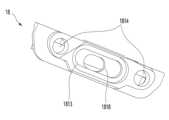
Figure 8 is a front perspective view of the sealing cover inserted into the front end of the flow guide.
Figure 9 is a rear perspective view of the sealing cover.
Figure 10 is an exploded perspective view showing the coupling relationship between the power module and the indicator module of the mask device according to an embodiment of the present invention.
Figure 11 is a front perspective view of an indicator body constituting an indicator module according to an embodiment of the present invention.
Figure 12 is a bottom view of the indicator body.
Figure 13 is a rear perspective view of the indicator body.
Figure 14 is an enlarged perspective view showing the back of the rear body with the filter housing and filter removed.
Figure 15 is an enlarged perspective view showing the back of the rear body with the flow guide removed.
Figure 16 is a front perspective view of the flow guide.
17 is a cut-away perspective view of a filter housing according to an embodiment of the present invention.
18 to 22 are cross-sectional views sequentially showing the process of closing the filter housing according to an embodiment of the present invention.
Figure 23 is a cut-away perspective view of a filter housing according to another embodiment of the present invention.
24 to 28 are cross-sectional views sequentially showing the process of closing a filter housing according to another embodiment of the present invention.
이하에서는 본 발명의 실시예에 따른 마스크 장치에 대하여 도면을 참조하여 상세히 설명하도록 한다.Hereinafter, a mask device according to an embodiment of the present invention will be described in detail with reference to the drawings.
도 1은 본 발명의 실시예에 따른 마스크 장치의 전면 사시도이고, 도 2는 상기 마스크 장치의 배면 사시도이며, 도 3은 상기 마스크 장치의 분해 사시도이고, 도 4는 상기 마스크 장치 내부에서의 공기 흐름을 보여주는 마스크 장치의 횡단면도이며, 도 5는 마스크 장치 내부에서의 공기 흐름을 보여주는 마스크 장치의 종단면도이다.Figure 1 is a front perspective view of a mask device according to an embodiment of the present invention, Figure 2 is a rear perspective view of the mask device, Figure 3 is an exploded perspective view of the mask device, and Figure 4 is an air flow inside the mask device. is a cross-sectional view of the mask device, and Figure 5 is a longitudinal cross-sectional view of the mask device showing the air flow inside the mask device.
도 1 내지 도 5를 참조하면, 본 발명의 실시예에 따른 마스크 장치(10)는, 마스크 바디(11)와, 상기 마스크 바디(11)의 배면에 고정 또는 분리 가능하게 결합되는 페이스 가드(14)와, 상기 마스크 바디(11)의 내부에 장착되는 에어 클리닝 모듈(30)을 포함한다.1 to 5, the
상세히, 상기 마스크 바디(11)는, 전면 외형을 이루는 프런트 바디(12)와, 상기 프런트 바디(12)의 배면에 결합되어 배면 외형을 이루는 리어 바디(13)를 포함한다. 상기 프런트 바디(12)의 전면은 상기 마스크 장치(10)의 전면을 형성하고, 상기 리어 바디(13)의 배면은 사용자(또는 착용자)의 안면과 마주한다.In detail, the
또한, 상기 페이스 가드(14)는 상기 리어 바디(13)의 배면에 결합되어 사용자의 안면에 밀착되며, 신축성을 가지는 실리콘 또는 고무 소재로 성형될 수 있다. 상기 페이스 가드(14)의 내측에는 호흡 공간이 형성되며, 사용자가 상기 마스크 장치(10)를 착용하면, 사용자의 코와 입이 상기 호흡 공간에 수용된다. 따라서, 상기 에어 클리닝 모듈(30)을 통과하면서 정화된 외부 공기가 상기 호흡 공간으로 안내되어, 사용자가 들이마시게 되고, 사용자가 내쉴 때 발생하는 공기도 상기 호흡 공간으로 배출된다.Additionally, the
상기 프런트 바디(12)와 상기 리어 바디(13) 사이에는 소정의 공간이 형성되며, 도 4 및 도 5에 보이는 바와 같이, 상기 리어 바디(13)의 전면에 각종 전장 부품이 장착된다. 그리고, 상기 각종 전장 부품은 상기 프런트 바디(12)에 의하여 차폐되어 외부로 노출되지 않는다.A predetermined space is formed between the
또한, 상기 에어 클리닝 모듈(30)은, 상기 리어 바디(13)에 형성된 수용부(133 : 도 6 참조)에 놓이는 팬 모듈(31)과, 상기 팬 모듈(31)의 후방에 놓이는 필터(33)를 포함한다. 상기 팬 모듈(31)은 축방향으로 공기를 흡입하여 반경 방향으로 토출하는 원심팬을 포함한다.In addition, the
상기 에어 클리닝 모듈(30)은, 상기 필터(33)의 후방에 놓이는 필터 하우징(34)을 더 포함하고, 상기 필터 하우징(34)에는 외부 공기가 흡입되는 흡입구(343)가 형성된다. 상기 필터 하우징(34)은 상기 리어 바디(13)에 회동 가능하게 결합될 수 있고, 상기 흡입구(343)는 도시된 바와 같이 직경이 다른 다수의 홀들의 집합일 수 있다.The
그리고, 상기 흡입구(343)로부터 상기 리어 바디(13)의 중심 방향으로 이격되는 지점에는 토출구(101)가 형성된다. 상기 팬 모듈(31)의 작동에 의하여 상기 흡입구 또는 흡입 그릴(343)을 통하여 흡입되는 외부 공기는 상기 필터(33)와 상기 팬 모듈(31)을 차례로 통과한 뒤 상기 토출구(101)를 통하여 상기 호흡 공간으로 토출된다.Also, an
상기 흡입구, 즉 흡입 그릴(343)은 상기 페이스 가드(14)의 외측에 배치되고, 상기 토출구(101)는 상기 페이스 가드(14)의 내측에 배치된다. 즉, 상기 흡입 그릴(343)은 상기 호흡 공간의 외측에 위치하고, 상기 토출구(101)는 상기 호흡 공간의 내측에 위치하여, 흡입되는 외부 공기와 사용자가 내뱉는 공기가 서로 혼합되지 않는다.The suction port, that is, the
한편, 상기 에어 클리닝 모듈(30)은, 상기 팬 모듈(31)의 후방에 배치되는 유동 가이드(32)를 더 포함한다.Meanwhile, the
또한, 상기 마스크 장치(10)는, 메인 제어 모듈(15)과, 전원 모듈(16)과, 인디케이터 모듈(18)과, 무선 통신 모듈(17)과, 스피커 모듈(19)과, 배터리(20), 및 배기 밸브(21) 중 적어도 하나를 더 포함한다.In addition, the
상세히, 상기 메인 제어 모듈(15)은 상기 팬 모듈(31)과 상기 스피커 모듈(19)을 비롯하여 압력 센서(미도시) 마이크(미도시) 등의 작동을 제어하기 위한 모듈이다. 상기 메인 제어 모듈(15)은 상기 리어 바디(13)의 전면 중앙의 상부에 배치될 수 있다.In detail, the
상기 전원 모듈(16)은, 상기 마스크 장치(10)에 장착되는 전장 부품들로 전원을 공급하기 위한 제어 모듈이다. 상기 전원 모듈(16)은 상기 리어 바디(13)의 전면 우측 하단에 배치될 수 있다.The
상기 전원 모듈(16)에는, 전원 공급 및 데이터 전송을 위한 케이블의 단자가 삽입되는 단자 연결부와, 마스크 장치(10)의 작동 상태를 알려주기 위해 사용되는 엘이디 모듈 등이 장착될 수 있다. 그리고, 상기 엘이디 모듈에서 조사되는 빛은 상기 인디케이터 모듈(18)을 통하여 확산 및 가이드되어 마스크 장치(10)의 외부로 방출된다.The
상기 무선 통신 모듈(17)은 블루투스를 비롯한 다양한 형태의 근거리 무선 통신 모듈 중 어느 하나일 수 있다. 상기 무선 통신 모듈(17)은 상기 리어 바디(13)의 전면 좌측 하단에 배치될 수 있다. 상기 무선 통신 모듈(17)은 상기 리어 바디(13)와 교차하는 방향, 일례로 수평하게 상기 리어 바디(13)의 전면에 장착될 수 있다. 상기 무선 통신 모듈(17)은, 상기 리어 바디(13)의 전면에서 돌출되는 한 쌍의 기판 삽입 리브(1315)에 의하여 수평한 상태로 상기 리어 바디(13)의 전면에 장착될 수 있다. 상기 무선 통신 모듈(17)의 양 측단부는 상기 한 쌍의 기판 삽입 리브(1315)에 의하여 지지된다.The
상기 스피커 모듈(19)은 상기 무선 통신 모듈(17)의 하측에 해당하는 상기 리어 바디(13)의 전면 좌측 하단에 배치될 수 있다.The
상기 배터리(20)는 상기 리어 바디(13)의 전면 중앙에 배치될 수 있고, 상기 배기 밸브(21)는 상기 리어 바디(13)의 전면 중앙의 하측에 형성된 배기구를 차폐하도록 배치될 수 있다. 즉, 사용자가 숨을 내쉴 때 상기 배기 밸브(21)는 상기 배기구를 개방하고, 사용자가 숨을 들이쉴 때 상기 배기 밸브(21)는 상기 배기구를 차폐할 수 있다. 상기 배기 밸브(21)는 휘어짐이 가능하고 납작한 플랩 형태로 제공될 수 있다.The
여기서, 상기 마스크 바디(11)의 전면, 후면, 좌측, 및 우측은, 사용자가 마스크 장치(10)를 착용한 상태를 기준으로 정의됨을 밝혀둔다.Here, it should be noted that the front, back, left, and right sides of the
한편, 도 4 및 도 5에 보이는 바와 같이, 사용자가 전원 버튼을 눌러서 상기 팬 모듈(31)을 작동시키면, 상기 마스크 장치(10)의 배면 좌측과 우측에 형성된 상기 흡입구(343)를 통하여 외부 공기가 상기 마스크 장치(10) 내부로 유입된다.Meanwhile, as shown in FIGS. 4 and 5, when the user operates the
상기 흡입구(343)를 통하여 유입되는 외부 공기는 상기 필터(33)를 통과하면서 정화된다. 그리고, 상기 필터(33)를 통과한 공기는 상기 팬 모듈(31)의 축 방향으로 흡입된 후 반경 방향으로 토출된다.External air flowing in through the
그리고, 상기 팬 모듈(31)의 반경 방향으로 토출되는 공기는 상기 유동 가이드(32)의 측면과 상기 수용부(133)의 에어 가이드면(1334:도6 참조)에 의하여 형성되는 에어 덕트102)를 통하여 상기 토출구(101)로 안내된다. 그리고, 상기 공기는 상기 토출구(101)를 통과하여 상기 페이스 가드(14) 내측에 정의되는 호흡 공간으로 공급된다.In addition, the air discharged in the radial direction of the
한편, 사용자가 내쉴 때 사용자의 입과 코를 통하여 배출되는 공기는 상기 호흡 공간에 모이게 된다. 그리고, 상기 호흡 공간에 모인 공기는 하강하여 전면 배기구(1361) 및 하면 배기구(1362)를 통하여 외부로 배출된다. 여기서, 사용자가 숨을 내쉴 때 발생하는 공기의 압력에 의하여 배기 밸브(20)가 전방으로 휘어지면서 상기 전면 배기구(1361)가 개방된다. 그리고, 사용자가 숨을 들이마실 때는 상기 호흡 공간 내부의 압력이 대기압보다 낮아지면서 상기 배기 밸브(20)가 원위치로 되돌아와서 상기 전면 배기구(1361)를 차폐하게 된다.Meanwhile, when the user exhales, the air discharged through the user's mouth and nose is collected in the breathing space. Then, the air collected in the breathing space descends and is discharged to the outside through the
상기 리어 바디(13)의 좌측단부와 우측 단부에는 스트랩 연결부(137)가 각각 형성된다. 상세히, 상기 스트랩 연결부(137)는, 사용자의 귀에 걸리거나 사용자의 후두부를 감싸는 스트랩 또는 밴드의 단부가 연결되는 부분이다. 상기 스트랩 연결부(137)는 상기 리어 바디(13)의 좌측단 상부와 하부, 우측단 상부와 하부에 각각 형성될 수 있다.
한 쌍의 스트랩 중 어느 하나의 양 단부는 좌측 상단과 하단에 구비되는 스트랩 연결부(137)에 각각 연결되고, 다른 하나의 양 단부는 우측 상단과 하단에 구비되는 스트랩 연결부(137)에 각각 연결될 수 있다. 그러면, 상기 한 쌍의 스트랩은 사용자의 양 쪽 귀에 각각 걸리도록 할 수 있다.Both ends of one of the pair of straps may be respectively connected to the
다른 방법으로서, 한 쌍의 스트랩 중 어느 하나의 양 단부는 좌측 상단과 우측 상단에 구비되는 스트랩 연결부(137)에 각각 연결되고, 다른 하나의 양 단부는 좌측 하단과 우측 하단에 구비되는 스트랩 연결부(137)에 각각 연결될 수 있다. 그러면, 상기 한 쌍의 스트랩은 사용자의 후두부에 둘러질 수 있다.As another method, both ends of one of the pair of straps are respectively connected to the
상기 네 개의 스트랩 연결부(137) 각각은, 상기 리어 바디(13)의 전면에서 함몰되되, 가로 방향(리어 바디의 폭 방향)으로 연장되는 스트랩 홈(1373)과, 상기 스트랩 홈(1373)의 어느 지점에 형성되는 스트랩 홀(1374)과, 상기 스트랩 홈(1373)의 상면과 하면을 연결하는 스트랩 바(1372)와, 상기 스트랩 홀(1374)의 가장자리에 해당하는 상기 리어 바디(13)의 배면에서 연장되는 통 형상의 방수 슬리브(1371 : 도 6 참조)를 포함한다. 그리고, 스트랩의 후크가 상기 스트랩 바(1372)에 회전 가능하게 걸리게 된다.Each of the four
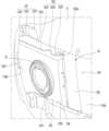
도 6은 본 발명의 실시예에 따른 마스크 장치를 구성하는 리어 바디의 전면 사시도이다.Figure 6 is a front perspective view of a rear body constituting a mask device according to an embodiment of the present invention.
도 6을 참조하면, 본 발명의 실시예에 따른 마스크 장치(10)를 구성하는 리어 바디(13)는, 사용자의 안면을 덮는 안면 커버부(131)와, 상기 안면 커버부(131)의 가장자리에서 전방으로 절곡되는 융착부(132)와, 상기 안면 커버부(131)의 전면으로부터 전방으로 돌출되어 상기 에어 클리닝 모듈(30)을 수용하는 한 쌍의 수용부(133)를 포함한다.Referring to FIG. 6, the
상세히, 상기 융착부(132)는, 상기 안면 커버부(131)의 상면 가장자리, 양 측면 가장자리, 및 하면 가장자리를 따라 연속적으로 형성된다. 그리고, 상기 안면 커버부(13)의 하면 가장자리를 따라 절곡되어 전방으로 연장되는 상기 융착부(132)의 전후 방향 폭이 가장 크다.In detail, the
상기 융착부(132) 중, 상기 안면 커버부(131)의 하면 가장자리에 형성되는 부분은 특별히 연장턱(1320)으로 정의될 수 있다. 상기 연장턱(1320)은, 상기 리어 바디(13)의 양 측단으로부터 중앙으로 갈수록 전후 방향 폭이 증가하는 형태로 볼록하게 라운드지는 형상을 이룬다.Among the fused
연장턱으로 정의되는 상기 융착부(132)의 중앙에는 상기 하면 배기구(1362)가 형성되고, 상기 하면 배기구(1362)로부터 상기 리어 바디(13)의 측단부 쪽으로 이격되는 지점에 버튼홀(1321)이 형성될 수 있다. 상기 버튼홀(1321)에는 전원 버튼이 삽입된다. 상기 버튼홀(1321)의 좌측 및 우측 가장자리에는 직경이 작은 한 쌍의 인디케이션 홀(1322)이 각각 형성된다.The lower
상기 전원 모듈(16)에 실장된 발광 수단으로부터 조사되는 빛은 상기 한 쌍의 인디케이션 홀(1322)을 통하여 외부로 방출된다. 상기 발광 수단은 LED 모듈을 포함한다.Light emitted from the light emitting means mounted on the
상기 한 쌍의 인디케이션 홀(1322) 중 어느 하나를 통하여 외부로 빛이 방출되면 상기 마스크 장치(10)의 전원이 온된 상태임을 의미할 수 있다. 그리고, 상기 한 쌍의 인디케이션 홀(1322) 중 다른 하나를 통하여 방출되는 빛의 색깔에 따라 상기 배터리(20)의 잔량을 예측할 수 있다.When light is emitted to the outside through one of the pair of
상기 버튼홀(1321)로부터 상기 리어 바디(13)의 측단부 쪽으로 더 이격되는 지점에는 단자 삽입구(1323)가 형성된다. USB(Universal Serial Bus) 케이블이 상기 단자 삽입구(1323)를 관통하여 상기 전원 모듈(16)에 형성된 단자 연결부(terminal connector)(162 : 도 9 참조)에 삽입될 수 있다. 상기 USB 케이블을 통하여 상기 배터리(20)가 충전되고, 상기 USB 케이블을 통하여 전송되는 데이터에 의하여 상기 마스크 장치(10)의 버전 또는 기능이 업데이트 또는 업그레이드될 수 있다.A
상기 한 쌍의 수용부(133)는 상기 리어 바디(13)의 중심으로부터 좌측과 우측에 각각 형성되며, 상기 리어 바디(13)의 중심을 지나는 수직선을 기준으로 대칭된다.The pair of receiving
상기 수용부(133) 각각은, 상기 안면 커버부(131)의 전면으로부터 전방으로 돌출됨으로써, 상기 에어 클리닝 모듈(30)을 수용하는 공간을 형성한다. 상기 수용부(133)는, 상기 에어 클리닝 모듈(30), 구체적으로 상기 팬 모듈(31)이 안착되는 안착면(1331)과, 상기 안면 커버부(131)의 측단부에서 상기 안착면(1331)의 외측 가장자리를 연결하는 체결면(1335)과, 상기 안착면(1331)의 내측 가장자리에서 상기 안면 커버부(131)의 전면을 연결하는 에어 가이드면(1334)을 포함한다. 상기 에어 가이드면(1334)은 상기 에어 덕트(101)의 전면을 형성한다.Each of the
또한, 상기 수용부(133)는, 상기 안착면(1331), 에어 가이드면(1334), 및 체결면(1335)의 상단들과 상기 안면 커버부(131)의 전면을 연결하는 상면(1332)을 더 포함한다.In addition, the receiving
그리고, 상기 수용부(133)는, 상기 안착면(1331), 에어 가이드면(1334), 및 체결면(1335)의 하단들과 상기 안면 커버부(131)의 전면을 연결하는 하면(1333)을 더 포함한다.In addition, the receiving
상기 체결면(1335)에는 하나 또는 다수의 체결 수단, 일례로 체결 후크(1338,1339 : 도 17 참조)가 형성된다.One or more fastening means, for example, fastening hooks 1338 and 1339 (see FIG. 17) are formed on the
상기 안착면(1331)에는 팬 장착홀(1336)이 형성되고, 상기 상면(1332)과 상기 하면(1334)은 수평하게 연장되며, 서로 평행하게 연장될 수 있다.A
상기 체결면(1335)은 상기 리어 바디(13)의 바깥쪽을 향하여 볼록하게 라운드지되, 상기 안면 커버부(131)로부터 상기 안착면(1331)으로 갈수록 경사지게 형성될 수 있다.The
상기 에어 가이드면(1334)은, 상기 안착면(1331)으로부터 상기 안면 커버부(131)를 향하여 볼록하게 라운드지게 연장되어, 상기 팬 모듈(31)에 의하여 흡입되는 공기가 상기 에어 가이드면(1334)을 따라 상기 토출구(101) 쪽으로 부드럽게 안내되도록 설계될 수 있다.The
상기 수용부(133)는, 상기 리어 바디(13)의 중심으로부터 좌측에 형성되는 좌측 수용부와, 상기 리어 바디(13)의 중심으로부터 우측에 형성되는 우측 수용부를 포함한다. 상기 좌측 수용부와 우측 수용부는 상기 리어 바디(13)의 중심으로부터 소정 간격 이격되고, 상기 좌측 수용부와 우측 수용부 사이의 공간에 상기 배터리(20)가 장착된다.The
상기 리어 바디(13)의 전면에는 배터리 장착부(138)가 형성될 수 있다. 상기 배터리 장착부(138)의 일 단부는 좌측의 에어 가이드면(1334)과 우측의 에어 가이드면(1334) 중 어느 일측에서 연장되고, 타 단부는 좌측의 에어 가이드면(1334)과 우측의 에어 가이드면(1334) 중 다른 일측에 연결된다.A
상기 배터리 장착부(138)는 n자 형상으로 이루어져서, 상기 배터리(20)의 전면과 양 측면을 지지한다. 따라서 상기 배터리 장착부(138)에 의하여 상기 배터리(20)가 상기 리어 바디(13)로부터 분리되는 현상이 방지될 수 있다.The
또한, 상기 배터리 장착부(138)의 중심부는 전방으로 더 돌출되어 크기가 다른 배터리를 선택적으로 장착 가능하게 한다.Additionally, the center of the
한편, 사용자가 상기 마스크 장치(10)를 착용한 상태에서 땀을 흘리면, 스트랩을 따라 상기 스트랩 홀(1374)로 땀이 흘러들어갈 수 있다. 뿐만 아니라, 마스크 장치(10)를 착용하지 않을 때에도 먼지나 기타 이물질이 상기 스트랩 홀(1374)로 유입될 수 있다.Meanwhile, if the user sweats while wearing the
그리고, 상기 스트랩 홀(1374)을 통하여 유입되는 수분은 상기 리어 바디(13)의 전면에 장착된 전장 부품을 부식시킬 수 있고, 유입되는 먼지로 인하여 전장 부품 주위에 스파크를 일으킬 수 있는 위험성이 있다.In addition, moisture flowing in through the
이러한 문제점을 개선하기 위해서, 상기 리어 바디(13)의 전면에 방수 슬리브(1371)가 형성된다. 상기 방수 슬리브(1371)는 상기 스트랩 홀(1374)의 가장자리를 따라 상기 리어 바디(13)의 전면으로부터 전방으로 소정 길이 연장된다.In order to improve this problem, a
그리고, 상기 방수 슬리브(1371)의 내측에는 실링캡((100)이 삽입되어, 상기 스트랩 홀(1374)을 통하여 유입되는 수분 및 이물질이 상기 프런트 바디(12)와 리어 바디(13) 사이의 공간으로 유입되는 것을 차단할 수 있다. 상기 방수 슬리브(1371)와 실링캡(100)의 구조에 대해서는 아래에서 도면을 참조하여 상세히 설명한다.Additionally, a sealing cap (100) is inserted inside the waterproof sleeve (1371) to prevent moisture and foreign substances flowing in through the strap hole (1374) from entering the space between the front body (12) and the rear body (13). The structure of the
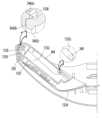
한편, 상기 배터리 장착부(138)의 하측에 해당하는 상기 안면 커버부(131)의 전면으로부터 배기 유로 가이드(136)가 전방으로 돌출된다. 그리고, 상기 배기 유로 가이드(136)의 전단부에는 실링 커버(60)가 장착되며, 상기 실링 커버(60)에 대해서는 아래에서 도면을 참조하여 상세히 설명한다.Meanwhile, an exhaust flow path guide 136 protrudes forward from the front of the
상세히, 상기 배기 유로 가이드(136)는 상기 배터리 장착부(138)의 하측에 형성되어, 상기 배터리 장착부(138)에 장착된 배터리(20)의 하단부가 상기 배기 유로 가이드(136)의 상면에 의하여 지지된다. 그 결과, 상기 배터리(20)가 상기 배터리 장착부(138)에 끼워진 상태에서 중력에 의하여 하측으로 빠지는 현상이 방지될 수 있다.In detail, the exhaust flow path guide 136 is formed on the lower side of the
상기 배기 유로 가이드(136)는 대략 터널 형태의 종단면을 형성할 수 있고, 상기 배기 유로 가이드(136)의 내측에 해당하는 상기 안면 커버부(131)에는 전면 배기구(1361)가 형성될 수 있다.The exhaust flow path guide 136 may have a longitudinal cross-section of approximately a tunnel shape, and a
상기 전면 배기구(1361) 및 상기 하면 배기구(1362) 중 적어도 하나는, 다수의 그릴 또는 구획 리브에 의하여 다수의 작은 배기구로 분할되는 배기 그릴 형태로 이루어질 수 있다. 그리고, 상기 전면 배기구(1361)는 상기 배기 밸브(21)에 의하여 선택적으로 개폐된다.At least one of the
도 7은 본 발명의 실시예에 따른 마스크 장치의 실링캡이 장착된 방수 슬리브 구조를 보여주는 확대 단면도이다.Figure 7 is an enlarged cross-sectional view showing the structure of a waterproof sleeve equipped with a sealing cap of a mask device according to an embodiment of the present invention.
도 7을 참조하면, 상기 방수 슬리브(1371)는 상기 프런트 바디(12)의 배면으로부터 이격되는 길이로 연장된다.Referring to FIG. 7, the
상세히, 상기 방수 슬리브(1371)가 상기 프런트 바디(12)의 배면에 닿는 길이로 연장되도록 하여, 수분 및 이물질이 상기 프런트 바디(12)와 리어 바디(13) 사이로 유입되는 것을 막는 것도 가능하다. 그러나, 상기 리어 바디(13)와 프런트 바디(12)가 결합된 상태에서, 조립 공차로 인하여 상기 방수 슬리브(1371)의 단부가 상기 프런트 바디(12)의 배면에 완전히 밀착되지 않는 현상이 발생할 가능성이 높다.In detail, it is possible to prevent moisture and foreign substances from flowing between the
또는, 상기 방수 슬리브(1371)의 단부가 상기 프런트 바디(12)의 배면에 열융착되도록 할 수 있으나, 열융착 과정에서 방수 슬리브(1371)가 녹아내리거나, 상기 프런트 바디(12)의 형상이 변형될 위험이 존재한다. 나아가, 상기 방수 슬리브(1371)의 단부가 열융착된 부분이 상기 마스크 장치(10)의 전면에 드러나서 미관상 좋지 않은 문제가 발생할 수 있다.Alternatively, the end of the
이러한 문제점을 해소하기 위해서, 상기 방수 슬리브(1371)의 횡단면 형상과 동일한 횡단면 구조를 가지고, 상기 방수 슬리브(1371)보다 짧은 길이를 가지는 상기 실링캡(100)이 상기 방수 슬리브(1371) 내부에 삽입되도록 할 수 있다.In order to solve this problem, the sealing
상기 실링 캡(100)은 탄성 변형 가능한 소재, 예컨대 실리콘 소재 또는 고무 소재로 이루어질 수 있다. 상기 실링캡(100)은, 상기 방수 슬리브(1371) 내부에 삽입되는 캡바디(1001)와, 상기 캡 바디(1001)의 상단에 형성되는 캡 커버(1002)를 포함한다. 상기 캡 커버(1002)의 너비는 상기 캡 바디(1001)의 너비보다 크게 형성되어, 상기 캡 커버(1002)가 상기 방수 슬리브(1371)의 단부에 걸리도록 함으로써, 상기 실링 캡(100)의 삽입 한도가 결정되도록 할 수 있다.The sealing
다른 방법으로, 상기 실링 캡(100)은 상기 방수 슬리브(1371)의 내부 형상과 동일한 형상으로 이루어지고, 상기 방수 슬리브(1371)의 내주면에 스토퍼 돌기(1375)가 돌출될 수 있다. 상기 스토퍼 돌기(1375)에 의하여 상기 실링 캡(100)의 삽입 한도가 결정될 수 있다.Alternatively, the sealing
그리고, 상기 실링캡(100)의 횡단면 크기를 상기 방수 슬리브(1371)의 횡단면 크기보다 약간 큰 사이즈로 제조하여, 상기 방수 슬리브(1371)에 밀어 넣으면, 상기 실링캡(100)의 표면과 상비 방수 슬리브(1371)의 내주면이 강하게 밀착되어, 실링 효과를 극대화할 수 있다.Then, when the cross-sectional size of the sealing
더 다른 방법으로서, 상기 방수 슬리브(1371)는 상기 스트랩 홀(1374)의 가장자리에서 전방으로 연장되되 횡단면적이 증가하는 형태로 경사지게 연장될 수 있다. 그러면, 상기 실링 캡(100)을 상기 방수 슬리브(1372)에 삽입할 때, 상기 실링 캡(100)의 삽입 깊이가 깊어질수록 상기 실링캡(100)의 압축량이 증가하면서 상기 실링캡(100)의 삽입 한계가 결정될 수 있다.As another method, the
도 8은 유로 가이드의 전단부에 삽입되는 실링 커버의 전면 사시도이고, 도 9는 상기 실링 커버의 배면 사시도이다.Figure 8 is a front perspective view of the sealing cover inserted into the front end of the flow guide, and Figure 9 is a rear perspective view of the sealing cover.
도 8 및 도 9를 참조하면, 상기 프런트 바디(12)가 상기 리어 바디(13)에 결합되면, 상기 배기 유로 가이드(136)의 전단부는 상기 프런트 바디(12)의 배면에 밀착되도록 설계된다.Referring to FIGS. 8 and 9 , when the
그러나, 조립 공차 또는 사출 후 수축에 의한 공차 등에 의하여, 상기 배기 유로 가이드(136)의 전단부가 상기 프런트 바디(12)의 배면으로부터 이격되어 틈새가 발생할 수 있다. 그리고, 우천 시 마스크 장치(10)를 쓰고 이동하거나 거친 운동을 하는 과정에서, 수분이나 침이 상기 틈새를 통하여 프런트 바디(12)와 리어 바디(30) 사이로 유입되는 현상이 발생할 수 있다.However, due to assembly tolerances or tolerances due to shrinkage after injection, the front end of the exhaust flow path guide 136 may be spaced apart from the rear surface of the
이러한 현상을 방지하기 위하여, 상기 방수 슬리브(1371)와 같이, 상기 배기 유로 가이드(136)의 전단부를 상기 프런트 바디(12)의 배면에 열융착시킬 수 있다. 그러면, 상기 방수 슬리브(1371)가 열융착되었을 때 발생하는 문제와 동일한 문제가 발생할 수 있다.To prevent this phenomenon, the front end of the exhaust flow path guide 136, like the
이와 같은 문제를 해소하기 위해서, 상기 배기 유로 가이드(136)의 전단부에 실링 커버(60)가 장착될 수 있다.To solve this problem, a sealing
상세히, 상기 실링 커버(60)는, 상기 실링 캡(100)과 마찬가지로, 실리콘이나 고무와 같은 탄성 소재로 이루어질 수 있다.In detail, the sealing
상기 실링 커버(60)는, 상기 배기 유로 가이드(136)의 전단부를 따라 연장되는 대략 n자 형태의 커버 프레임(601)과, 상기 커버 프레임(601)의 내측 가장자리에서 후방으로 연장되는 내측 리브(604)와, 상기 커버 프레임(601)의 외측 가장자리에서 후방으로 연장되는 외측 리브(603), 및 상기 커버 프레임(601)의 좌측 부분과 우측 부분을 연결하는 연결 리브(602)를 포함한다.The sealing
상기 내측 리브(604)와 외측 리브(603) 사이에는 상기 배기 유로 가이드(136)의 두께에 대응하는 크기의 폭을 가지는 끼움홈(605)이 형성되어, 상기 끼움홈(605)에 상기 배기 유로 가이드(136)의 전단부가 삽입된다.A
또한, 상기 연결 리브(602)가 형성됨으로써, 상기 커버 프레임(601)의 양 단부가 벌어지는 현상을 방지할 수 있다.In addition, by forming the connecting
그리고, 상기 실링 커버(60)의 양측 하단부는, 상기 안면 커버부(131)의 하면 가장자리에 형성되는 상기 연장턱(1320)에 닿는 길이로 형성된다. 그러면, 상기 프런트 바디(12)가 상기 리어 바디(13)에 결합될 때, 상기 실링 커버(60)의 하단부와 상기 연장턱(1320) 사이에 틈새가 발생하지 않는다.In addition, the lower ends on both sides of the sealing
도 10은 본 발명의 실시예에 따른 마스크 장치의 전원 모듈과 인디케이터 모듈의 결합 관계를 보여주는 분해 사시도이다. Figure 10 is an exploded perspective view showing the coupling relationship between the power module and the indicator module of the mask device according to an embodiment of the present invention.
도 10을 참조하면, 마스크 장치(10)에 장착되는 전원 모듈(16)은, 상기 리어 바디(13)의 전면 우측 하단에 배치되고, 상기 인디케이터 모듈(18)은 상기 전원 모듈(16)의 기판 상에 조립되어 결합된다.Referring to FIG. 10, the
상세히, 상기 전원 모듈(16)은, 전원 기판(161)과, 상기 전원 기판(161)의 전면에 실장되는 다수의 전장 부품을 포함한다. 상기 다수의 전장 부품은, 단자 연결부(162)와, 커넥터(163)와, 전원 스위치(164) 및 엘이디(165,166) 중 적어도 하나를 포함한다.In detail, the
상기 단자 연결부(162)는, 외부로부터 USB 케이블이 삽입되어 상기 배터리(200)가 충전되거나, 상기 USB 케이블을 통하여 전송되는 데이터에 의하여 상기 마스크 장치(10)의 버전 또는 기능이 업데이트 또는 업그레이드되기 위한 인터페이스 기능을 한다.The terminal connection unit 162 is used to charge the battery 200 by inserting a USB cable from the outside, or to update or upgrade the version or function of the
상기 커넥터(163)는, 상기 메인 제어 모듈(15)의 피시비를 연결하여 상기 메인 제어 모듈(15)로 전원을 제공하는 기능을 한다.The connector 163 functions to provide power to the
상기 전원 스위치(164)는, 상기 버튼 홀(1321)에 장착되는 전원 버튼(183)에 의하여 온 또는 오프된다. 상기 전원 스위치(164)는 상기 전원 기판(161)의 좌측 하단에 실장될 수 있다.The power switch 164 is turned on or off by the
상기 전원 스위치(164)가 상기 전원 버튼(183)의 조작에 의해 온 되면, 상기 마스크 장치(10)에 장착되는 전장 부품들로 전원이 공급되고, 상기 전원 버튼(183)의 조작에 의해 오프 되면, 상기 마스크 장치(10)에 장착되는 전장 부품들로 전원 공급이 차단된다.When the power switch 164 is turned on by manipulating the
상기 엘이디(165,166)는, 상기 마스크 장치(10)의 작동 상태를 알려주기 위해 외부로 빛을 방출한다. 상기 엘이디(165,166)에서 조사되는 빛은 상기 인디케이터 모듈(18)을 통하여 확산 및 가이드되어 마스크 장치(10)의 외부로 방출된다. 상기 인디케이터 모듈(18)이 상기 전원 기판(161)에 결합되면, 상기 엘이디(165,166)는 상기 인디케이터 모듈(18)에 의해 차폐되거나, 상기 인디케이터 모듈(18)의 내부에 수용된다.The LEDs 165 and 166 emit light to the outside to inform the operating state of the
상기 엘이디(165,166)는 상기 전원 스위치(164)를 기준으로 좌우 양측에 각각 이격되어 배치된다. 상기 엘이디(165,166)는, 상기 전원 스위치(164)의 우측으로 이격되는 제 1 엘이디(165)와, 좌측으로 이격되는 제 2 엘이디(166)를 포함한다.The LEDs 165 and 166 are arranged to be spaced apart from each other on both left and right sides with respect to the power switch 164. The LEDs 165 and 166 include a first LED 165 spaced to the right of the power switch 164 and a second LED 166 spaced to the left.
또한, 상기 전원 기판(161)에는, 상기 인디케이터 모듈(18)이 장착되기 위한 장착홀(167,168)이 형성된다. 상기 장착홀(167,168)은 상기 인디케이터 모듈(18)의 일부분이 후크 방식으로 걸림 결합되는 부분이다.Additionally, mounting holes 167 and 168 for mounting the
상기 장착홀(167,168)은, 상기 전원 스위치(164)를 기준으로 좌우 양측에 각각 이격되어 배치된다. 상기 장착홀(167,168)은, 상기 전원 스위치(164)의 우측으로 이격되는 제 1 장착홀(167)과, 좌측으로 이격되는 제 2 장착홀(168)을 포함한다. 상기 제 1 장착홀(167)은 상기 제 1 엘이디(165)의 상측으로 이격되고, 상기 제 2 장착홀(168)은 상기 제 2 엘이디(166)의 상측으로 이격된다.The mounting holes 167 and 168 are arranged to be spaced apart from each other on both left and right sides with respect to the power switch 164. The mounting holes 167 and 168 include a first mounting hole 167 spaced to the right of the power switch 164 and a second mounting hole 168 spaced to the left. The first mounting hole 167 is spaced above the first LED 165, and the second mounting hole 168 is spaced above the second LED 166.
상기 인디케이터 모듈(18)은, 상기 전원 기판(161)에 장착되며, 상기 엘이디(165,166)의 빛을 집광시켜 상기 마스크 장치(10)의 외부로 확산 및 가이드 하는 기능을 한다.The
상기 인디케이터 모듈(18)은, 인디케이터 바디(181)와, 상기 인디케이터 바디(181)의 저면 내측에 삽입되는 버튼 실링부(182)와, 상기 버튼 실링부(182)의 내측에 삽입되는 전원 버튼(183) 및 상기 인디케이터 바디(18)의 내부에 삽입되는 도광부(184)를 포함한다.The
상기 버튼 실링부(182)는, 내측에 상기 전원 버튼(183)이 삽입되는 삽입 공간을 형성하는 실링부 바디(1821)를 포함한다. 상기 실링부 바디(1821)는, 내측에 상기 전원 버튼(183)이 삽입된 상태에서 상기 버튼 장착부(1812)의 저면에 형성된 버튼 장착홈(1813:도 11 참조)장착된다. 상기 실링부 바디(1821)는 상기 버튼 장착홈(1813)의 내측을 감싸도록 배치될 수 있다. 상기 실링부 바디(1821)는 고무 또는 실리콘 재질로 형성될 수 있다.The
상기 실링부 바디(1821)의 삽입 공간은, 상기 실링부 바디(1821)의 저면에서 상방으로 함몰되어 형성될 수 있다. 상기 버튼 실링부(182)가 상기 버튼 장착홈(1813)에 삽입되면, 상기 실링부 바디(1821)의 저면은, 상기 버튼 장착부(1812)의 저면과 단차없이 매끄럽게 단일 면을 형성할 수 있다.The insertion space of the
상기 실링부 바디(1821)는, 상기 전원 버튼(183)과 상기 리어 바디(13)의 버튼 홀(1321) 사이의 공간으로 유입된 수분 또는 이물질이 상기 전원 기판(161) 측으로 유입되는 것을 방지하는 기능을 한다. 이를 위하여, 상기 실링부 바디(1821)는 상기 버튼 홀(1321)과 마주하도록 배치되며, 상기 버튼 홀(1321)의 단면적 보다 큰 단면적을 가질 수 있다. 따라서, 상기 전원 기판(161)에 실장된 다수의 전장 부품들이 방수 처리되고 외부로부터 보호될 수 있다.The sealing
또한, 상기 실링부 바디(1821)의 상면에는, 상기 전원 버튼(183)의 일부가 통과하는 관통 보스(1822)가 형성된다. 상기 관통 보스(1822)는, 내부에 상기 전원 버튼(183)이 통과하는 개구가 형성되며, 상기 실링부 바디(1821)의 상면 중심에서 상방으로 돌출될 수 있다.Additionally, a through
상기 관통 보스(1822)는 상기 전원 스위치(164)와 마주하여 배치된다. 따라서, 상기 전원 버튼(183)이 가압되면, 상기 전원 버튼(183)의 일부분이 상기 관통 보스(1822)를 통과하여 상기 전원 스위치(164)에 접촉할 수 있다. 상기 전원 스위치(164)는 택트 스위치를 포함한다.The through
상기 전원 버튼(183)은, 사용자에 의해 가압되어 상기 전원 스위치(164)를 작동시키는 구성으로 이해될 수 있다. 상기 전원 버튼(183)은 상기 버튼 실링부(182)의 내측에 삽입된 상태에서, 상기 버튼 홀(1321)을 통과하여 상기 마스크 장치(10)의 외부로 노출될 수 있다.The
한 실시예에 따르면, 상기 전원 버튼(183)은 상기 버튼 실링부(182)와 상기 리어 바디(13)의 사이에서 상하 방향으로 소정거리 이동 가능하도록 탄력적으로 설치될 수 있다. 이를 위하여, 상기 전원 버튼(183)과 상기 버튼 실링부(182)의 사이에는 탄성부재가 개재될 수 있다. 상기 탄성부재는 스프링을 포함할 수 있다.According to one embodiment, the
상기 전원 버튼(183)은, 상기 버튼 실링부(182)에 장착되며 사용자에 의해 가압되는 버튼 바디(1831)와, 상기 버튼 바디(1831)의 상면에서 돌출되어 상기 전원 스위치(164)에 접촉하는 버튼 돌기(1832)를 포함할 수 있다.The
상기 버튼 돌기(1832)는, 상기 버튼 바디(1831)의 상면 중심에서 상방으로 돌출될 수 있다. 상기 버튼 돌기(1832)는 상기 관통 보스(1822)와 마주하게 배치될 수 있다. 따라서, 상기 버튼 바디(1831)가 외력에 의해 가압되면, 상기 버튼 돌기(1832)가 상기 관통 보스(1822)를 통과하여 상기 전원 스위치(164)를 가압하게 된다.The
상기 도광부(184)는, 상기 인디케이터 바디(181)의 내부에 수용되어, 상기 엘이디(165,166)에서 방출되는 광이 퍼지지 않고 상기 인디케이션 홀(1322)을 향하도록 안내하는 기능을 한다. 상기 도광부(184)는 한 쌍으로 형성되어, 한 쌍의 리플렉터(1815)의 내측에 각각 수용된다. 상기 도광부(184)는 상기 베이스(1811)의 상면에 장착되고 일부분이 상기 도광부 홀(1814)에 삽입될 수 있다.The
상세히, 상기 도광부(184)는, 관 형상으로 형성되어 상기 인디케이션 홀(1322)에 삽입되는 관부(1841)와, 상기 관부(1841)의 상단에서 확관되어 연장되는 연장관(1842)과, 상기 연장관(1842)의 상단에 형성되어 상기 베이스(1811)의 상면에 고정되는 고정부(1843)를 포함할 수 있다.In detail, the
상기 관부(1841)의 중심은, 상기 인디케이션 홀(1322)의 중심과 일치할 수 있다. 상기 연장관(1842)은, 상기 도광부 홀(1814)의 내경과 대응하는 면적의 외경을 가지며, 상기 도광부 홀(1814)에 상단에 삽입될 수 있다. 상기 고정부(1843)는 상기 베이스(1811)의 상면에 고정된 상태에서, 상기 엘이디(165,166)와 마주하게 배치될 수 있다. 이때 상기 고정부(1843)에는 상기 연장관(1842)과 연통되는 개구가 형성된다.The center of the
따라서, 상기 엘이디(165,166)에서 발생된 광은, 상기 리플렉터(1815)에 의해 집광되어 상기 도광부(184)의 내부로 안내된다. 그리고 상기 도광부(184)를 통과한 광은 상기 인디케이션 홀(1322)을 통하여 상기 마스크 장치(10)의 외부로 확산되어 방출된다.Accordingly, the light generated from the LEDs 165 and 166 is collected by the
도 11은 본 발명의 실시예에 따른 인디케이터 모듈을 구성하는 인디케이터 바디의 전면 사시도이고, 도 12는 상기 인디케이터 바디의 저면도이며, 도 13은 상기 인디케이터 바디의 배면 사시도이다.Figure 11 is a front perspective view of an indicator body constituting an indicator module according to an embodiment of the present invention, Figure 12 is a bottom view of the indicator body, and Figure 13 is a rear perspective view of the indicator body.
도 11 내지 도 13을 참조하면, 본 발명의 실시예에 따른 인디케이터 모듈(18)를 구성하는 인디케이터 바디(181)는, 상기 인디케이터 바디(181)는, 베이스(1811)와, 상기 베이스(1811)의 저면에서 하방으로 연장되는 버튼 장착부(1812)와, 상기 베이스(1811)의 상면 양측에서 각각 상방으로 연장되는 한 쌍의 리플렉터(1815), 및 상기 한 쌍의 리플렉터(1815)를 연결하는 휨 방지벽(1819)를 포함한다. 또한, 상기 인디케이터 바디(181)는 상기 한 쌍의 리플렉터(1815)의 상면에 각각 형성되는 걸림부(1816,1817)를 더 포함할 수 있다.11 to 13, the
상기 베이스(1811)는, 좌우 방향으로 길게 연장되는 형상으로 형성된다. 상기 베이스(1811)의 중심은, 상기 전원 스위치(164)의 중심과 정렬될 수 있다. 상기 베이스(1811)의 상면 중심에는, 상기 전원 버튼(183)이 통과하는 버튼 통과홀(1818)이 형성된다. 상기 전원 버튼(183)이 가압되면, 상기 전원 버튼(183)이 상기 버튼 통과홀(1818)을 통과하여 상기 전원 스위치(164)를 가압하게 된다.The
상기 버튼 장착부(1812)는, 상기 베이스(1811)의 저면에서 좌우 방향으로 길게 형성된다. 이때 상기 버튼 장착부(1812)의 중심은, 상기 베이스(1811)의 중심과 정렬될 수 있다. 상기 버튼 장착부(1812)의 중심에는, 상기 전원 버튼(183)이 삽입되는 버튼 장착홈(1813)이 형성된다. 상기 버튼 장착홈(1813)은, 상기 버튼 장착부(1812)의 저면에서 상방으로 함몰되어 형성될 수 있다. 상기 버튼 장착홈(1813)은 상기 버튼 통과홀(1818)과 연결된다.The
또한, 상기 버튼 장착부(1812)의 저면에는, 상기 도광부(184)가 삽입되기 위한 도광부 홀(1814)이 형성된다. 상기 도광부 홀(1814)은, 상기 버튼 장착부(1812)의 저면에서 상방으로 관통되어 형성될 수 있다. 이때, 상기 도광부 홀(1814)은 상기 버튼 장착부(1812)의 저면에서 상기 베이스(1811)의 상면까지 관통될 수 있다.In addition, a
상기 도광부 홀(1814)은, 상기 버튼 장착홈(1813)의 양측으로 각각 이격되어 형성된다. 한 쌍의 도광부 홀(1814)은 한 쌍의 인디케이션 홀(1322)과 각각 마주하여 연결될 수 있다.The
상기 리플렉터(1815)는, 상기 엘이디(165,166)를 수용하는 수용공간을 형성하여, 상기 엘이디(165,166)에서 방출하는 빛을 집광시키는 기능을 한다. 상기 리플렉터(1815)는 상기 베이스(1811)의 상면에서 상기 버튼 통과홀(1818)을 기준으로 양측으로 각각 이격되어 형성된다.The
상기 리플렉터(1815)는, 상기 베이스(1811)의 상면 양측에서 각각 상방으로 연장되고, 전면과 양측면 및 상면은 폐쇄되고 배면은 개방되는 형상을 가질 수 있다. 그리고 상기 인디케이터 모듈(18)이 상기 전원 기판(161)에 결합되면, 상기 전원 기판(161)에 실장된 상기 엘이디(165,166)는 상기 리플렉터(1815)의 내부 공간에 수용된다. 상기 리플렉터(1815)의 수용공간은, 상기 도광부 홀(1814)과 연결된다.The
상기 걸림부(1816,1817)는, 상기 리플렉터(1815)에 형성되어 상기 장착홀(167,168)에 결합되는 부분이다. 상기 걸림부(1816,1817)는 상기 리플렉터(1815)의 상면에서 연장되는 연장부(1816)와, 상기 연장부(1816)의 단부에 형성되는 후크부(1817)를 포함한다.The locking
상기 연장부(1816)는, 상기 리플렉터(1815)의 상면에서 후방으로 연장되고, 그 단부에 상기 후크부(1817)가 구비될 수 있다. 한 쌍의 후크부(1817)는, 한 쌍의 장착홀(167,168)에 각각 후크 체결됨으로써, 상기 인디케이터 모듈(18)이 상기 전원 기판(161)에 흔들림 없이 안정적으로 고정될 수 있다.The
상기 인디케이터 모듈(18)이 상기 마스크 장치에 조립된 상태에서, 사용자가 사기 전원 버튼(183)을 상기 전원 스위치(164)를 향하여 가압하면, 상기 전원 버튼(183)을 가압하는 힘에 의하여 상기 베이스(1811)의 중심이 상측으로 볼록하게 라운드지게 휘어질 수 있다. 그리고, 상기 베이스(1811)가 휘어짐에 따라 상기 한 쌍의 리플렉터(1815)는 서로 멀어지는 방향으로 벌어지거나 휘어지게 된다. 이러한 현상에 의하여, 상기 전원 스위치(164)에 과도한 힘이 전달되어 파손되는 문제가 발생한다.When the
이러한 문제를 해결하기 위하여, 상기 한 쌍의 리플렉터(1815)가 상기 휨 방지벽(1819)에 의하여 연결되도록 한다. 상기 휨 방지벽(1819)은 상기 한 쌍의 리플렉터(1815)의 전면 내측 가장자리들을 연결한다. 그리고, 상기 휨 방지벽(1819)의 하단과 상기 베이스(1811)의 상면이 만나는 지점에는 단차부(1819a)가 형성될 수 있다.To solve this problem, the pair of
상기 휨 방지벽(1819) 및 상기 단차부(1819a)에 의하여, 상기 전원 버튼(183)에 과도한 힘이 작용하더라도, 상기 베이스(1811)가 휘어지는 현상이 발생하지 않으므로, 상기 전원 기판(161)에 실장된 부품이 파손되거나, 상기 도광부(184)와 상기 인디케이션 홀의 정렬 상태가 흐트러지는 현상을 방지할 수 있다.Due to the bending
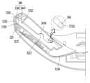
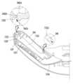
도 14는 필터 하우징과 필터가 제거된 상태의 리어 바디의 배면을 보여주는 확대 사시도이고, 도 15는 유동 가이드가 제거된 상태의 리어 바디의 배면을 보여주는 확대 사시도이며, 도 16은 유동 가이드의 전면 사시도이다.Figure 14 is an enlarged perspective view showing the rear body with the filter housing and filter removed, Figure 15 is an enlarged perspective view showing the rear body with the flow guide removed, and Figure 16 is a front perspective view of the flow guide. am.
도 14 내지 도 16을 참조하면, 상술한 바와 같이, 상기 에어 클리닝 모듈(30)이 수용되는 상기 수용부(133)는, 상기 에어 클리닝 모듈(30), 구체적으로 상기 팬 모듈(31)이 안착되는 안착면(1331)과, 상기 안면 커버부(131)의 측단부에서 상기 안착면(1331)의 외측 가장자리를 연결하는 체결면(1335)과, 상기 안착면(1331)의 내측 가장자리에서 상기 안면 커버부(131)의 전면을 연결하는 에어 가이드면(1334)을 포함한다. 상기 에어 가이드면(1334)은 상기 에어 덕트(101)의 전면을 형성한다.14 to 16, as described above, the
상기 체결면(1335)에는 유동 가이드 후크(1339 : 도 18 참조)와 필터 후크(1338)가 각각 전후 방향으로 이격되어 형성된다. 상기 필터 후크(1338)보다 상기 유동 가이드 후크(1339)가 상기 안착면(1331)에 더 가까이 위치한다.On the
그리고, 상기 필터 후크(1338)의 후방에 해당하는 상기 리어 바디(13)의 배면 측단에는 파지홈(1337)이 형성된다.Additionally, a
또한, 상기 수용부(133)는, 상기 안착면(1331), 에어 가이드면(1334), 및 체결면(1335)의 상단들과 상기 안면 커버부(131)의 전면을 연결하는 상면(1332)을 더 포함한다.In addition, the receiving
그리고, 상기 수용부(133)는, 상기 안착면(1331), 에어 가이드면(1334), 및 체결면(1335)의 하단들과 상기 안면 커버부(131)의 전면을 연결하는 하면(1333)을 더 포함한다.In addition, the receiving
상세히, 상기 수용부(133)의 상면(1332)과 하면(1333) 각각에는 장착 가이드(1332a)와, 고정 가이드(1332b) 및 힌지홀(1332c)이 형성된다.In detail, a mounting
상기 장착 가이드(1332a)는 상기 마스크 바디(11)의 후면에서 전면 방향으로 소정 길이 연장되는 리브 형태로 제공된다. 상기 고정 가이드(1332b)는 상기 장착 가이드(1332a)로부터 상기 마스크 바디(11)의 중심 방향으로 이격되는 지점에서 돌출되는 돌기 형태로 제공된다.The mounting
또한, 상기 힌지홀(1332c)은 상기 장착 가이드(1332a)로부터 상기 마스크 바디(11)의 측단부 쪽으로 이격되는 지점에서 장홀 형태로 제공된다. 상기 힌지홀(1332c)은 상기 필터 하우징(34)의 힌지(346 : 도 17 참조)가 삽입되는 홀로서, 비 원형 형상으로 이루어질 수 있으며, 일례로 타원 형상의 장홀일 수 있다.Additionally, the
또한, 상기 힌지홀(1332c)은 상기 마스크 바디(11)의 측단부로 갈수록 상기 마스크 바디(11)의 배면에 가까워지는 방향으로 비스듬히 연장될 수 있다. 즉, 타원형의 상기 힌지홀(1332c)이 설계될 때, 상기 마스크 바디(11)의 중심에 가까운 상기 힌지홀(1332c)의 일 단부로부터 상기 마스크 바디(11)의 배면에 이르는 거리는, 상기 마스크 바디(11)의 측단부에 가까운 상기 힌지홀(1332c)의 타 단부로부터 상기 마스크 바디(11)의 배면에 이르는 거리보다 길게 설계될 수 있다.Additionally, the
상기 힌지홀(1332c)이 장홀 형태로 비스듬하게 연장되는 이유는, 상기 필터(33)를 분리하기 위하여 상기 필터 하우징(34)의 단부를 회전시킬 때, 상기 필터 하우징(34)이 상기 유동 가이드(32)의 리어 플랜지(325)와 간섭되지 않도록 하기 위함이다.The reason why the
상세히, 상기 필터 하우징(34)의 체결 후크(344 : 도 17 참조)가 상기 체결면(1335)에 돌출된 필터 후크(1338)로부터 분리된 상태에서, 상기 필터 하우징(34)을 회전 시킬 때, 상기 필터 하우징(34)을 상기 마스크 바디(11)의 측단부 쪽으로 잡아당기면서 회전시킨다. 그리면, 상기 필터 하우징(34)의 힌지(346)가 상기 장홀 형태의 힌지홀(1332c)의 일 단부에서 타 타단부 쪽으로 이동하면서 회전하여, 도 18과 같은 상태가 된다.In detail, when the
이러한 본 발명의 힌지홀(1332c) 구조에 의하면, 상기 필터 하우징(34)이 상기 리어 플랜지(325)와 간섭되지 않으면서도, 상기 힌지홀(1332c)이 원형인 경우에 비하여 상기 필터 하우징(34)의 회전량(또는 개방각)이 더 커지는 장점이 있다. 그 결과 상기 필터(33)의 장착과 분리가 훨씬 더 용이하게 이루어질 수 있는 장점이 있다.According to the hinge hole (1332c) structure of the present invention, the filter housing (34) does not interfere with the rear flange (325), and compared to the case where the hinge hole (1332c) is circular, the filter housing (34) There is an advantage that the rotation amount (or opening angle) becomes larger. As a result, there is an advantage that the installation and removal of the
한편, 상기 팬 모듈(31)은, 팬 하우징(311)과 팬(312)을 포함한다. 그리고, 상기 팬 하우징(311)은, 상기 수용부(133)의 안착면(1331)에 안착되는 베이스(3111)와, 상기 베이스(3111)의 가장자리에서 소정 높이로 돌출되는 쉬라우드(3112)를 포함한다. 상기 쉬라우드(3112)는 상기 베이스(311)의 가장자리를 따라 둘러지되, 중간 부분은 상기 팬(312)의 외곽을 따라 라운드지게 연장된다.Meanwhile, the
상기 베이스에는 팬 모터 구동을 위한 피시비(F)가 배치된다. 상기 피시비는 휘어짐이 가능한 연성 피시비(Flexible PCB)를 포함한다.A PCB (F) for driving the fan motor is disposed on the base. The PCB includes a flexible PCB that can be bent.
상기 쉬라우드(3112)는 상기 베이스(3111)의 일단부의 일측 가장자리에서 직선으로 연장되다가, 어느 지점에서 상기 팬(313)의 외곽을 따라 소정 곡률로 라운드지게 연장된 다음, 상기 베이스(3111)의 일단부의 타측 가장자리까지 직선으로 연장된다.The
상기 쉬라우드(3112)의 일측 단부의 내면에는 가이드 돌기(3113)가 돌출되고, 상기 가이드 돌기(3113)와 상기 팬(312) 사이의 공간에서부터 공기가 팬의 회전 방향으로 회전하여 상기 가이드 돌기(3113)와 마주보는 상기 쉬라우드(3112)의 측단부 쪽으로 토출된다.A guide protrusion 3113 protrudes on the inner surface of one end of the
상기 가이드 돌기(3113)가 형성되는 부분, 즉 공기의 회전이 시작되는 부분을 입구(a)로 정의할 수 있고, 상기 쉬라우드(3112)의 형상을 따라 회전하는 공기가 빠져나가는 부분을 출구(b)로 정의할 수 있다.The part where the guide protrusion 3113 is formed, that is, the part where air rotation begins, can be defined as the inlet (a), and the part through which air rotating along the shape of the
상기 출구(b)로 빠져나가는 공기는 상기 토출구(101)를 통하여 사용자의 안면으로 공급된다.The air escaping through the outlet (b) is supplied to the user's face through the outlet (101).
한편, 상기 팬 모듈(31)이 상기 수용부(133)에 장착된 상태에서, 상기 유동 가이드(32)가 상기 팬 모듈(31)의 배면에 놓인다. 즉, 상기 유동 가이드(32)가 상기 쉬라우드(3112)의 후단에 놓인다.Meanwhile, when the
상기 유동 가이드(32)는, 상기 팬 하우징(311)의 개방된 후면을 덮는 마운트 플레이트(321)와, 상기 마운트 플레이트(31)의 일단에서 절곡 연장되는 덕트 플랜지(324)와, 상기 마운트 플레이트(321) 및 상기 덕트 플랜지(324)의 상단에서 절곡 연장되는 어퍼 플랜지(322)와, 상기 마운트 플레이트(321) 및 상기 덕트 플랜지(324)의 하단에서 절곡 연장되는 로어 플랜지(323), 및 상기 덕트 플랜지(324)의 단부에서 상기 덕트 플랜지(324)와 교차하는 방향으로 연장되는 리어 플랜지(325)를 포함한다.The flow guide 32 includes a
상기 마운트 플레이트(321)의 타단은 상기 수용부(133)의 체결면(1335)에 밀착된다. 그리고, 상기 마운트 플레이트(321)에는 연통홀(3211)이 형성되며, 상기 연통홀(3211)은 상기 팬 모듈(31)의 흡입구로 기능한다.The other end of the
상기 어퍼 플랜지(322)는, 마운트 어퍼 플랜지(3221)와 덕트 어퍼 플랜지(3222), 및 가이드 숄더(3223)를 포함한다.The
상기 마운트 어퍼 플랜지(3221)는, 상기 마운트 플레이트(321)의 상단에서 수직하게 절곡되어 소정의 폭을 가지고 연장된다. 상기 덕트 어퍼 플랜지(3222)는 상기 덕트 플랜지(324)의 상단에서 수직하게 절곡되어 소정의 폭을 가지고 연장된다. 상기 마운트 어퍼 플랜지(3221)와 상기 덕트 어퍼 플랜지(3222)는 한 몸으로 이루어져서 L자형 형상을 이룬다.The mount
상기 로어 플랜지(323)는, 마운트 로어 플랜지(3231)와 덕트 로어 플랜지(3232), 및 가이드 숄더(3233)를 포함한다.The
상기 마운트 로어 플랜지(3231)는 상기 마운트 플레이트(321)의 하단에서 수직하게 절곡되어 소정의 폭을 가지고 연장된다. 상기 덕트 로어 플랜지(3232)는 상기 덕트 플랜지(324)의 하단에서 수직하게 절곡되어 소정의 폭을 가지고 연장된다.The mount
상기 어퍼 플랜지(322)와 상기 로어 플랜지(323)는 상기 마운트 플레이트(321)를 상하로 이등분하는 선 또는 면을 기준으로 대칭되는 형상으로 이루어진다.The
상기 가이드 숄더(3223,3233)에 대해서는 아래에서 도면을 참조하여 더욱 상세히 설명한다.The guide shoulders 3223 and 3233 will be described in more detail below with reference to the drawings.
상기 어퍼 플랜지(322)는 상기 수용부(133)의 상면(1332)에 밀착되고, 상기 로어 플랜지(323)는 상기 수용부(133)의 하면(1333)에 밀착된다. 그리고, 상기 유동 가이드(32)가 상기 수용부(133)에 안착되면, 도 4에 보이는 바와 같이, 상기 덕트 플랜지(324)는 상기 에어 덕트(102)의 배면을 형성하고, 상기 수용부(133)의 에어 가이드면(1334)은 상기 에어 덕트(102)의 전면을 형성한다.The
상기 리어 플랜지(325)는. 상기 유동 가이드(32)가 상기 수용부(133)에 장착되면, 상기 마스크 바디(11)의 배면 일부를 형성한다. 그리고, 상기 리어 플랜지(325)의 일 측단부는 상기 필터 하우징(34)의 단부와 접하고, 상기 리어 플랜지(325)의 타 측단부는 상기 토출구(101)의 측단부를 형성한다.The
상세히, 상기 에어 덕트(102)의 출구단으로 정의되는 상기 토출구(101)는, 상기 수용부(133)를 구성하는 에어 가이드면(1334)의 단부와, 상기 리어 플랜지(325)의 타 측단부에 의하여 정의되는 것으로 이해될 수 있다.In detail, the
또한, 상기 마운트 플레이트(321)와, 상기 덕트 플랜지(324)와, 상기 어퍼 플랜지(322)와, 상기 로어 플랜지(323) 및 상기 리어 플랜지(325)의 일부분에 의하여 상기 필터(33)가 수용되는 공간이 정의된다.In addition, the
상기 어퍼 플랜지(322)와 상기 로어 플랜지(323)는 상기 필터(33)의 네 측면들 중 상부 측면 일부와 하부 측면 일부를 각각 지지하여, 사용자가 상기 마스크 장치(10)를 착용한 상태에서 상기 필터가 상하 방향으로 요동하는 것을 차단한다.The
또한, 상기 덕트 플랜지(324)는, 상기 마운트 플레이트(321)의 측단부에서 절곡 연장되어 상기 필터(33)의 측면 일부를 지지하는 필터 지지면(3241)과, 상기 필터 지지면(3241)의 단부에서 절곡 연장되는 절곡면(3242), 및 상기 절곡면(3242)의 단부에서 소정 곡률로 라운드지는 에어 가이드면(3243)을 포함한다.In addition, the
상기 덕트 플랜지(324)의 에어 가이드면(3243)은 상기 수용부(133)를 구성하는 에어 가이드면(1334)과 마주보는 위치에 형성되며, 상기 두 개의 에어 가이드면(3243,1334)에 의하여 상기 에어 덕트(102)의 전면과 후면이 정의되는 것으로 이해될 수 있다.The
상기 에어 가이드면(3243)의 라운드지는 형상에 의하여, 상기 에어 덕트(102)는 상기 팬 모듈(31)의 토출구와 연통하는 흡입구로부터 상기 토출구(101)로 갈수록 단면적이 증가하는 형태로 이루어질 수 있다. Due to the round shape of the
한편, 상기 어퍼 플랜지(322)의 덕트 어퍼 플랜지(3222)와, 상기 로어 플랜지(323)의 덕트 로어 플랜지(3232) 각각에는, 가이드 홈(3201)과 고정홈(3202)이 형성된다.Meanwhile, a
상기 가이드 홈(3201)은, 상기 절곡면(3242)으로부터 상기 리어 플랜지(325)로부터 하측으로 이격되는 어느 지점까지 형성된다. 상기 유동 가이드(32)가 상기 수용부(133)에 장착될 때, 상기 가이드 홈(3201)에는 상기 장착 가이드(1332a)가 슬라이딩 삽입된다.The
여기서, 상기 장착 가이드(1332a)가 상기 유동 가이드(32)의 덕트 어퍼 플랜지(3222)에 형성되고, 상기 가이드 홈(3201)이 상기 수용부(133)의 상면(1332)과 하면(1333)에 각각 형성되어도 무방하다.Here, the mounting
상기 장착 가이드(1332a)가 상기 가이드 홈(3201)에 삽입됨으로서, 상기 팬 모듈(31)로부터 상기 에어 덕트(102)로 토출되는 공기의 일부가 누설되는 현상을 방지할 수 있다. 구체적으로, 상기 에어 덕트(102)로 토출되는 공기의 일부가, 상기 수용부(133)의 상면(1332)과 상기 유동 가이드(32)의 어퍼 플랜지(322) 사이의 틈새, 및 상기 수용부(133)의 하면(1333)과 상기 유동 가이드(32)의 로어 플랜지(323) 사이의 틈새를 통하여 누설되는 현상이 방지된다.By inserting the mounting
또한, 상기 고정 가이드(1332b)는 상기 고정홈(3202)에 억지 끼움되어, 상기 유동 가이드(32)가 상기 수용부(133)에 흔들림 없이 결합될 수 있다. 물론, 상기 고정 가이드(1332b)와 상기 고정홈(3202)의 위치 또한 상기 장착 가이드(1332a)와 상기 가이드 홈(3201)와 마찬가지로 서로 바뀌어도 무방하다.Additionally, the fixing
한편, 상기 마운트 플레이트(321)의 전면, 즉 상기 팬 하우징(311)의 개방된 면을 덮는 면에는 팬 지지 리브(3212)가 형성될 수 있다.Meanwhile, a
상세히, 상기 팬 지지 리브(3212)는 상기 팬 하우징(311)을 구성하는 상기 쉬라우드(3112)의 형상을 따라 돌출되고, 상기 쉬라우드(3112)의 바깥 면을 따라 연장되어, 상기 팬 하우징(311)을 안정적으로 지지할 수 있다. 상기 연통홀(3211)은 상기 팬 지지 리브(3212)의 내측 영역에 형성된다.In detail, the
또한, 상기 팬 지지 리브(3212)의 외측 영역에 해당하는 상기 마운트 플레이트(321)의 전면 가장자리에는 팬 고정 보스(327)가 돌출될 수 있다. 상기 팬 고정 보스(327)는, 상기 마운트 플레이트(321)의 바깥쪽 측단부의 상측 모서리에 형성되는 제 1팬 고정 보스와, 하측 모서리에 형성되는 제 2 팬 고정 보스를 포함할 수 있다. 상기 마운트 플레이트(321)의 바깥쪽 측단부는 상기 수용부(133)의 체결면(1335)에 밀착되는 단부를 의미하는 것으로 이해될 수 있다.Additionally, a
또한, 상기 팬 고정 보스(327)로부터 이격되는 어느 지점에는 체결 보스(328)가 돌출된다. 상기 체결 보스(328)는 상기 유동 가이드(32)를 상기 수용부(133)의 안착면(1331)에 고정시키기 위한 수단으로 이해될 수 있다.Additionally, a
상기 체결 보스(328)는, 상기 제 1 팬 고정 보스로부터 이격되는 지점에 형성되는 제 1 체결 보스와, 상기 제 2 팬 고정 보스로부터 이격되는 지점에 형성되는 제 2 체결 보스를 포함할 수 있다. 상기 체결 보스(328)와 팬 고정 보스(327)의 개수는 제시되는 실시예에 제한되지 않음을 밝혀둔다.The
또한, 상기 마운트 플레이트(321)의 전면의 외측 가장자리, 즉 상기 마운트 플레이트(321)의 바깥쪽 측단부에 인접하는 영역에는 체결 후크(329)가 돌출 형성될 수 있다. 상기 체결 후크(329)는 상기 수용부(133)의 체결면(1335)에 돌출된 유동 가이드 후크(1339)에 걸려서, 상기 유동 가이드(32)의 탈거를 방지한다.Additionally, a
여기서, 상기 체결 후크(329), 체결 보스(328), 및 팬 고정 보스(327)는, 상기 마운트 플레이트(321)를 상하로 이등분하는 선을 기준으로 대칭되게 형성될 수 있다.Here, the
한편, 상기 베이스(3111)의 제조 과정에서 상기 베이스(3111)의 휘어짐이 발생하거나, 상기 유동 가이드(32)의 마운트 플레이트(321)에 압력이 가해지면, 상기 팬 모듈(31)의 피시비(F)가 상기 마운트 플레이트(321)와 간섭되어 파손되거나, 상기 팬(312)의 블레이드가 상기 마운트 플레이트(321)에 닿아서 소음을 발생시킨다.Meanwhile, if the
이러한 현상을 방지하기 위하여, 상기 마운트 플레이트(321)의 전면 일측에는 휨방지 보스(326)가 돌출될 수 있다. 구체적으로, 상기 휨 방지 보스(326)는 상기 덕트 플랜지(324)에 인접하는 상기 마운트 플레이트(321)의 전면 가장자리에서 돌출된다.To prevent this phenomenon, a bending
또한, 상기 팬 모듈(31)에서 토출되는 공기의 유동이 상기 휨방지 보스(326)에 의하여 방해되지 않도록 하기 위하여, 상기 마운트 플레이트(321)의 전면 가장자리 중 상기 팬 모듈(31)의 입구(a) 측에 대응하는 가장자리에 형성되는 것이 좋다.In addition, in order to prevent the flow of air discharged from the
따라서, 상기 유동 가이드(32)가 상기 팬 모듈(31)의 쉬라우드(3112)에 안착되면, 상기 휨방지 보스(326)의 단부는 상기 입구(a) 영역에 해당하는 상기 베이스의 면에 닿게 된다(도 15에 도시된 점선 원 참조).Therefore, when the
상기 휨방지 보스(326)에 의하여, 상기 베이스(3111)의 휨 또는 상기 마운트 플레이트(321)에 작용하는 외력에 의하여 피시비(F)가 간섭되거나 팬(312)의 블레이드가 마운트 플레이트(321)에 닿아서 소음을 발생시키는 현상이 발생하지 않게 된다.Due to the bending-
여기서, 상기 휨방지 보스(326)가 상기 마운트 플레이트(321)의 전면 상측과 하측 가장자리에 각각 형성되는 것을 배제하지는 않는다. 즉, 두 개의 휨방지 보스(326)가 서로 대칭되는 위치에서 돌출되어, 상기 입구(a) 영역 및 상기 출구(b) 영역에 닿는 것도 가능함을 밝혀둔다.Here, it is not excluded that the bending-
도 17은 본 발명의 실시예에 따른 필터 하우징의 절개 사시도이다.Figure 17 is a cut-away perspective view of a filter housing according to an embodiment of the present invention.
도 17을 참조하면, 본 발명의 실시예에 따른 필터 하우징(34)의 전면은 상기 유동 가이드(32)의 배면에 안착되는 필터(33)의 배면과 마주보고, 상기 필터 하우징(34)의 배면은 상기 마스크 바디(11)의 배면 일부를 형성한다. 즉, 사용자가 상기 마스크 장치(10)를 착용하면, 상기 필터 하우징(34)의 배면은 사용자의 안면과 마주한다.Referring to FIG. 17, the front of the
상세히, 상기 필터 하우징(34)은, 상기 필터(33)의 세 측면을 감싸는 필터 프레임(341)과, 상기 필터 프레임(341)의 배면에 형성되는 필터 커버(342)를 포함한다.In detail, the
상기 필터 커버(342)는, 상기 흡입구(343)가 형성되고, 전면에 상기 필터 프레임(341)이 연장되는 커버 본체(342a)와, 상기 커버 본체(342a)의 일 측단부에서 연장되는 연장부(342b)로 이루어지는 것으로 설명될 수 있다.The
상기 연장부(342b)는, 상기 마스크 바디(11)의 배면 윤곽에 맞게 부드럽게 라운드지게 형성될 수 있다. 상기 연장부(342b)의 단부에는 상기 파지홈(3421)이 형성될 수 있다. 상기 필터 커버(342)를 닫으면 상기 파지홈(3421)은 상기 리어 바디(13)의 측단부에 형성된 파지홈(1337:도 14 참조)에 맞닿는다.The
또한, 상기 연장부(342b)의 전면 중앙에는 체결 후크(344)가 돌출된다. 상기 필터 커버(342)를 닫으면, 상기 체결 후크(344)는 상기 필터 후크(1338)에 걸리게 되어, 상기 필터 커버(342)가 상기 리어 바디(13)에 고정 결합된다(도 22 참조).Additionally, a
상기 필터 하우징(34)의 내측 단부, 즉 상기 연장부(342b)의 반대측 단부의 양 측면에는 힌지(346)가 돌출된다. 상기 힌지(346)는 장홀 형태로 형성되는 상기 힌지홀(1332c)에 삽입되어, 상기 필터 하우징(34)의 개폐 과정에서 상기 힌지홀(1332c)의 일단에서 타단 사이를 이동하게 된다.
상세히, 상기 필터 프레임(341)은, 상기 커버 본체(342a)의 일 측단부 전면에서 전방으로 연장되는 측면 프레임(3411)과, 상기 커버 본체(342a)의 상단부 전면에서 전방으로 연장되는 상면 프레임(3412)과, 상기 상면 프레임(3412)의 맞은 편에 형성되는 하면 프레임을 포함한다. 따라서, 상기 필터(33)의 세 측면만 상기 필터 프레임(341)에 의하여 둘러진다.In detail, the
상기 상면 프레임(3412)과 하면 프레임에는 가이드 홈(3414)이 형성되고, 상기 가이드 홈(3414)에는 상기 유동 가이드(32)의 가이드 숄더(3223,3233)가 수용된다. 상기 필터를 삽입 후 상기 필터 하우징(34)을 닫을 때, 상기 가이드 홈(3414)과 상기 가이드 숄더(3223,3233)의 맞물림 과정에 의하여, 상기 필터 하우징(34)의 체결 후크(344)가 상기 필터 후크(1338)에 부드럽게 걸리게 된다. 이에 대한 내용은 아래에서 도면을 참조하여 상세히 설명한다.A
또한, 상기 측면 프레임(3411)은 상기 필터 커버(342)를 상기 커버 본체(342a)와 상기 연장부(342b)로 구분하는 경계면으로 설명될 수도 있다.Additionally, the
도 18 내지 도 22는 본 발명의 실시예에 따른 필터 하우징의 닫음 과정을 순차적으로 보여주는 단면도이다.18 to 22 are cross-sectional views sequentially showing the process of closing the filter housing according to an embodiment of the present invention.
도 18 내지 도 22를 참조하면, 상술한 바와 같이, 상기 필터 하우징(34)의 힌지(346)는 비스듬히 연장되는 장홀 형태의 힌지홀(1332c)에 삽입된다.18 to 22, as described above, the
상세히, 상기 필터 하우징(34)의 체결 후크(344)가 상기 필터 후크(1338)에서 분리되도록, 사용자는 상기 연장부(342b)의 끝을 잡고 들어 올린다. 상기 체결 후크(344)가 상기 필터 후크(1338)로부터 분리되면, 사용자는 상기 연장부(342b)의 끝을 잡고 마스크 바디(11)의 측단부 쪽으로 잡아당기면서 위로 들어올린다. 그러면, 상기 힌지(346)가 상기 힌지홀(1332c)의 일 단부에서 타단부 쪽으로 이동하면서 상기 필터 하우징(34)의 개방 각도가 증가하게 된다. 그 결과, 상기 필터 하우징(34)이 상기 유동 가이드(32)의 리어 플랜지(325)와 간섭되지 않고 개방된다.In detail, the user holds and lifts the end of the
도 18은 상기 필터 하우징(34)이 최대한 개방된 상태를 보여주는 단면도로서, 상기 힌지(346)가 상기 힌지홀(1332c)의 타단에 위치한 상태이다.Figure 18 is a cross-sectional view showing the
이 상태에서, 상기 힌지(346)가 상기 힌지홀(1332c)의 일단에 닿을 때까지 상기 필터 하우징(34)을 밀어넣은 다음 닫지 않으면, 상기 체결 후크(344)의 걸림부(3442)가 상기 필터 후크(1338)의 바깥쪽 면을 따라 미끄러지면서 후크 결합이 되지 않는 상황이 발생할 수 있다. 나아가, 사용자가 과도한 힘으로 상기 필터 하우징(34)을 닫을 경우 상기 체결 후크(344)가 부러지는 현상이 발생할 수도 있다.In this state, if the
본 발명은, 사용자가 힌지(346)를 힌지홀(1332c)의 일단에 닿도록 밀어넣지 않은 상태에서 상기 필터 하우징(34)을 닫는 동작을 하더라도, 체결 후크(344)가 필터 후크(1338)에 정확하게 결합되도록 하는 구조가 제공된다.In the present invention, even if the user closes the
일례로서, 상기 유동 가이드(32)에 가이드 숄더(3223,3233)가 라운드지게 돌출되도록 하고, 상기 필터 하우징(34)의 측면에 가이드 홈(3414)이 형성되도록 한다. 그리고, 상기 필터 하우징(34)을 닫으면 상기 가이드 홈(3414)이 상기 가이드 숄더(3223,3233)의 라운드진 면을 따라 미끄러지면서, 상기 가이드 숄더(3223,3233)가 상기 가이드 홈(3414)에 정확하게 결합되면서, 상기 제?r 후크(344)의 걸림부(3442)가 상기 필터 후크(1338)의 안쪽 면에 걸리게 된다.As an example, guide
도 18 내지 도 22에 도시된 바와 같이, 상기 필터 하우징(34)의 개방각이 점진적으로 감소함에 따라, 상기 가이드 홈(3414)은 상기 가이드 숄더(3223,3233)에 결합되는 위치로 이동한다. 동시에, 상기 힌지(346)는 상기 힌지홀(1332c)의 타단에서 일단으로 이동하게 된다.18 to 22, as the opening angle of the
도 23은 본 발명의 다른 실시예에 따른 필터 하우징의 절개 사시도이다.Figure 23 is a cut-away perspective view of a filter housing according to another embodiment of the present invention.
도 23을 참조하면, 본 발명의 다른 실시예에 따른 ??터 하우징(34)의 상면프레임(3412)과 하면 프레임(3413)에 가이드 홈이 별도로 형성되지 않고, 유동 가이드(32)에도 가이드 숄더가 형성되지 않는다.Referring to FIG. 23, guide grooves are not separately formed in the
다만, 상기 체결 후크(344)의 단부 형상이 개선되어, 필터 하우징(34)을 닫을 때 체결 후크(344)와 필터 후크(3818)의 체결이 안정적으로 이루어지도록 한다.However, the end shape of the
상세히, 상기 체결 후크(344)는, 상기 필터 커버(342)로부터 연장되는 연장부(3441)와, 상기 연장부(3441)의 단부에 형성되는 걸림부(3442)를 포함한다.In detail, the
상기 걸림부(3442)는, 상기 필터 하우징(34)의 외측 가장자리 쪽으로 경사지는 걸림면(3442a)과, 상기 걸림면(3442a)의 단부에서 직선 형태로 연장되는 미끄럼면(3442b)과, 상기 미끄럼면(3442b)의 단부에서 소정 곡률로 라운드지는 접촉면(3442c)을 포함한다.The engaging
상기 접촉면(3442c)은, 상기 필터 하우징(34)을 닫으면 상기 필터 후크(1338)에 가장 먼저 닿는 면이다.The
도 24 내지 도 28은 본 발명의 다른 실시예에 따른 필터 하우징의 닫음 과정을 순차적으로 보여주는 단면도이다.24 to 28 are cross-sectional views sequentially showing the process of closing a filter housing according to another embodiment of the present invention.
도 24 내지 도 28을 참조하면, 필터 하우징(34)이 개방된 상태에서 힌지(346)는 상기 힌지홀(1332c)의 타단에 걸린 상태가 된다.Referring to FIGS. 24 to 28, when the
이 상태에서 사용자가 상기 힌지(346) 쪽 필터 하우징(34)의 단부를 밀어넣지 않고 회전하는 경우, 즉 도 24의 화살표 방향으로 필터 하우징(34)을 밀어서 닫는 경우, 도 26에 보이는 바와 같이, 상기 필터 후크(1338)의 첨단은 상기 접촉면(3442c)에 닿는다.In this state, when the user rotates the end of the
상기 필터 후크(1338)의 첨단이 상기 접촉면(3442c)에 닿은 상태에서 상기 필터 하우징(34)의 배면을 더 누르면, 도 27에 보이는 바와 같이, 상기 필터 후크(1338)의 첨단은 상기 접촉면(3442c)을 따라 이동하면서 상기 미끄럼면(3442b)에 도달한다. 상기 필터 후크(1338)의 첨단이 상기 접촉면(3442c)과 미끄럼면(3442b)을 따라 이동할 때 상기 힌지(346)는 상기 힌지홀(1332c)의 일단 쪽으로 이동하게 된다.If the rear surface of the
이 상태에서 상기 필터 하우징(34)의 배면을 완전히 닫으면, "딸깍" 소리와 함께 상기 필터 후크(1338)의 안쪽 면이 상기 걸림면(3442a)에 닿으면서, 상기 걸림부(3442)가 상기 필터 후크(1338)에 걸리게 된다.In this state, when the back of the
상기 체결 후크(344)의 걸림부(3442)의 형상에 의하여, 사용자가 상기 필터 하우징(34)을 닫는 경우에 상기 체결 후크(344)의 단부가 상기 필터 후크(1338)의 바깥 쪽 면을 따라 미끄러지지면서 상기 체결 후크(344)가 파손되는 현상이 발생하지 않는다.Due to the shape of the catching
Claims (9)
Translated fromKorean상기 프런트 바디의 배면에 결합되고, 전면으로부터 상기 프런트 바디 쪽으로 돌출되는 한 쌍의 수용부와, 상기 한 쌍의 수용부의 하측에 형성되는 배기구와, 상기 배기구의 가장자리를 따라 전방으로 돌출되는 배기 유로 가이드를 포함하는 리어 바디;
상기 리어 바디의 배면에 결합되어 사용자의 안면에 밀착되고, 내측에 호흡 공간이 형성되는 페이스 가드;
상기 수용부에 놓여서, 내부로 유입되는 외부 공기를 정화하여 상기 호흡 공간으로 공급하는 에어 클리닝 모듈; 및
상기 배기 유로 가이드의 단부에 끼워지는 실링 커버를 포함하고,
상기 실링 커버는,
상기 배기 유로 가이드의 전면을 따라 형성되는 커버 프레임;
상기 커버 프레임의 좌측 부분과 우측 부분을 연결하는 연결 리브;
상기 커버 프레임의 내측 가장자리에서 후방으로 연장되는 내측 리브; 및
상기 커버 프레임의 외측 가장자리에서 후방으로 연장되는 외측 리브를 포함하고,
상기 배기 유로 가이드는, 상기 내측 리브와 상기 외측 리브 사이에 형성되는 끼움홈에 삽입되는 것을 특징으로 하는 마스크 장치.front body;
A pair of receiving portions coupled to the rear surface of the front body and protruding from the front toward the front body, an exhaust port formed on a lower side of the pair of receiving portions, and an exhaust flow path guide protruding forward along an edge of the exhaust port. A rear body including;
A face guard coupled to the back of the rear body, adhered to the user's face, and forming a breathing space on the inside;
An air cleaning module placed in the receiving unit to purify external air flowing into the interior and supply it to the breathing space; and
It includes a sealing cover fitted to an end of the exhaust flow path guide,
The ceiling cover is,
a cover frame formed along the front of the exhaust flow path guide;
A connecting rib connecting the left and right portions of the cover frame;
an inner rib extending rearward from the inner edge of the cover frame; and
comprising an outer rib extending rearward from an outer edge of the cover frame,
The mask device is characterized in that the exhaust flow path guide is inserted into a fitting groove formed between the inner rib and the outer rib.
상기 배기 유로 가이드의 내부에 배치되어, 상기 배기구를 차폐하는 배기 밸브를 더 포함하는 마스크 장치.According to claim 1,
The mask device further includes an exhaust valve disposed inside the exhaust flow path guide and shielding the exhaust port.
상기 끼움홈은, 상기 배기 유로 가이드의 두께에 대응하는 크기의 폭을 가지는 것을 특징으로 하는 마스크 장치.According to claim 1,
The mask device is characterized in that the fitting groove has a width corresponding to the thickness of the exhaust flow path guide.
상기 실링 커버는,
고무 또는 실리콘 소재로 이루어지는 것을 특징으로 하는 마스크 장치.According to claim 1,
The ceiling cover is,
A mask device characterized in that it is made of rubber or silicone material.
상기 실링 커버는 상기 리어 바디의 하단부 가장자리까지 연장되는 길이로 형성되는 것을 특징으로 하는 마스크 장치.According to claim 1,
The mask device is characterized in that the sealing cover is formed in a length extending to the lower edge of the rear body.
상기 한 쌍의 수용부는,
상기 리어 바디의 중심을 지나는 수직면을 기준으로 좌우 대칭되게 형성되는 것을 특징으로 하는 마스크 장치.According to claim 1,
The pair of receiving portions,
A mask device characterized in that it is formed left and right symmetrically with respect to a vertical plane passing through the center of the rear body.
상기 에어 클리닝 모듈은,
상기 수용부에 놓이는 팬 모듈;
상기 팬 모듈의 후방에 놓이는 유동 가이드;
상기 유동 가이드에 안착되어, 상기 팬 모듈로 유입되는 외부 공기를 정화하는 필터;
상기 필터의 측면을 감싸는 필터 프레임과, 상기 필터의 후면을 덮는 필터 커버로 이루어지는 필터 하우징;을 포함하는 마스크 장치.According to claim 1,
The air cleaning module,
a fan module placed in the receiving portion;
a flow guide placed behind the fan module;
a filter mounted on the flow guide to purify external air flowing into the fan module;
A mask device comprising a filter housing consisting of a filter frame surrounding a side of the filter and a filter cover covering a rear side of the filter.
상기 필터 커버에는, 외부 공기를 흡입하는 흡입구가 형성되는 것을 특징으로 하는 마스크 장치.According to claim 7,
A mask device characterized in that an intake port for sucking in external air is formed in the filter cover.
상기 수용부의 내측 가장자리와 상기 유동 가이드의 내측 가장자리 사이에 토출구가 형성되는 것을 특징으로 하는 마스크 장치.According to claim 8,
A mask device characterized in that a discharge port is formed between an inner edge of the receiving portion and an inner edge of the flow guide.
Priority Applications (4)
| Application Number | Priority Date | Filing Date | Title |
|---|---|---|---|
| KR1020220096133AKR102681889B1 (en) | 2022-08-02 | 2022-08-02 | Mask apparatus |
| CN202211348685.XACN117531136A (en) | 2022-08-02 | 2022-10-31 | Mask device |
| US18/080,154US20240042250A1 (en) | 2022-08-02 | 2022-12-13 | Mask apparatus |
| EP23159965.5AEP4327890A1 (en) | 2022-08-02 | 2023-03-03 | Mask apparatus |
Applications Claiming Priority (1)
| Application Number | Priority Date | Filing Date | Title |
|---|---|---|---|
| KR1020220096133AKR102681889B1 (en) | 2022-08-02 | 2022-08-02 | Mask apparatus |
Publications (2)
| Publication Number | Publication Date |
|---|---|
| KR20240018178A KR20240018178A (en) | 2024-02-13 |
| KR102681889B1true KR102681889B1 (en) | 2024-07-04 |
Family
ID=85461926
Family Applications (1)
| Application Number | Title | Priority Date | Filing Date |
|---|---|---|---|
| KR1020220096133AActiveKR102681889B1 (en) | 2022-08-02 | 2022-08-02 | Mask apparatus |
Country Status (4)
| Country | Link |
|---|---|
| US (1) | US20240042250A1 (en) |
| EP (1) | EP4327890A1 (en) |
| KR (1) | KR102681889B1 (en) |
| CN (1) | CN117531136A (en) |
Family Cites Families (10)
| Publication number | Priority date | Publication date | Assignee | Title |
|---|---|---|---|---|
| US4687212A (en)* | 1986-12-16 | 1987-08-18 | Baraw Corporation | Seal assembly with stabilizing ribs |
| US5372130A (en)* | 1992-02-26 | 1994-12-13 | Djs&T Limited Partnership | Face mask assembly and method having a fan and replaceable filter |
| CN107847824B (en)* | 2015-06-30 | 2020-10-27 | 3M创新有限公司 | Filter cartridge including filter media with adhesively sealed edge ends and methods of manufacture and use |
| KR101930144B1 (en) | 2015-12-29 | 2018-12-18 | 한가현 | Mask for health care of cutting off harmful materials by using air curtain |
| KR101619487B1 (en)* | 2016-02-17 | 2016-05-10 | (주)대성엠텍 | Functional mask |
| KR101942785B1 (en)* | 2016-07-18 | 2019-01-28 | 신홍제 | Functional mask |
| CN208145256U (en)* | 2018-03-15 | 2018-11-27 | 厦门伊亚创新科技有限公司 | It is a kind of can be according to the filter face mask of human body respiration rate adaptation intake |
| CA3101837A1 (en)* | 2018-06-01 | 2019-12-05 | Safebvm Corp. | Pressure safety device for bag valve mask |
| US11666787B2 (en)* | 2018-12-26 | 2023-06-06 | Lg Electronics Inc. | Mask apparatus |
| KR102426354B1 (en)* | 2021-07-19 | 2022-07-29 | 엘지전자 주식회사 | Mask apparatus |
- 2022
- 2022-08-02KRKR1020220096133Apatent/KR102681889B1/enactiveActive
- 2022-10-31CNCN202211348685.XApatent/CN117531136A/enactivePending
- 2022-12-13USUS18/080,154patent/US20240042250A1/enactivePending
- 2023
- 2023-03-03EPEP23159965.5Apatent/EP4327890A1/enactivePending
Also Published As
| Publication number | Publication date |
|---|---|
| US20240042250A1 (en) | 2024-02-08 |
| KR20240018178A (en) | 2024-02-13 |
| CN117531136A (en) | 2024-02-09 |
| EP4327890A1 (en) | 2024-02-28 |
Similar Documents
| Publication | Publication Date | Title |
|---|---|---|
| CN115634383B (en) | Mask device | |
| CN115634387B (en) | Mask device | |
| KR102681889B1 (en) | Mask apparatus | |
| KR102631285B1 (en) | Mask apparatus | |
| KR102653008B1 (en) | Mask apparatus | |
| KR20240018183A (en) | Mask apparatus | |
| KR20240018180A (en) | Mask apparatus | |
| KR20240018185A (en) | Mask apparatus | |
| KR102611200B1 (en) | Mask apparatus | |
| KR102600006B1 (en) | Mask apparatus | |
| KR102497331B1 (en) | Mask apparatus | |
| KR102497328B1 (en) | Mask apparatus | |
| CN115634388B (en) | Mask device | |
| CN115634385B (en) | Mask device | |
| KR102493267B1 (en) | Mask apparatus | |
| HK40078394A (en) | Mask apparatus | |
| HK40080424A (en) | Mask apparatus | |
| HK40078395A (en) | Mask apparatus |
Legal Events
| Date | Code | Title | Description |
|---|---|---|---|
| PA0109 | Patent application | Patent event code:PA01091R01D Comment text:Patent Application Patent event date:20220802 | |
| PA0201 | Request for examination | ||
| PE0902 | Notice of grounds for rejection | Comment text:Notification of reason for refusal Patent event date:20230927 Patent event code:PE09021S01D | |
| PG1501 | Laying open of application | ||
| PE0701 | Decision of registration | Patent event code:PE07011S01D Comment text:Decision to Grant Registration Patent event date:20240628 | |
| PR0701 | Registration of establishment | Comment text:Registration of Establishment Patent event date:20240701 Patent event code:PR07011E01D | |
| PR1002 | Payment of registration fee | Payment date:20240702 End annual number:3 Start annual number:1 | |
| PG1601 | Publication of registration |