KR102681871B1 - Aerosol generating device - Google Patents
Aerosol generating deviceDownload PDFInfo
- Publication number
- KR102681871B1 KR102681871B1KR1020210095617AKR20210095617AKR102681871B1KR 102681871 B1KR102681871 B1KR 102681871B1KR 1020210095617 AKR1020210095617 AKR 1020210095617AKR 20210095617 AKR20210095617 AKR 20210095617AKR 102681871 B1KR102681871 B1KR 102681871B1
- Authority
- KR
- South Korea
- Prior art keywords
- cover
- generating device
- aerosol generating
- guide
- hole
- Prior art date
- Legal status (The legal status is an assumption and is not a legal conclusion. Google has not performed a legal analysis and makes no representation as to the accuracy of the status listed.)
- Active
Links
Images


Classifications
- A—HUMAN NECESSITIES
- A24—TOBACCO; CIGARS; CIGARETTES; SIMULATED SMOKING DEVICES; SMOKERS' REQUISITES
- A24F—SMOKERS' REQUISITES; MATCH BOXES; SIMULATED SMOKING DEVICES
- A24F40/00—Electrically operated smoking devices; Component parts thereof; Manufacture thereof; Maintenance or testing thereof; Charging means specially adapted therefor
- A24F40/50—Control or monitoring
- A24F40/53—Monitoring, e.g. fault detection
- A—HUMAN NECESSITIES
- A24—TOBACCO; CIGARS; CIGARETTES; SIMULATED SMOKING DEVICES; SMOKERS' REQUISITES
- A24F—SMOKERS' REQUISITES; MATCH BOXES; SIMULATED SMOKING DEVICES
- A24F40/00—Electrically operated smoking devices; Component parts thereof; Manufacture thereof; Maintenance or testing thereof; Charging means specially adapted therefor
- A24F40/40—Constructional details, e.g. connection of cartridges and battery parts
- A—HUMAN NECESSITIES
- A24—TOBACCO; CIGARS; CIGARETTES; SIMULATED SMOKING DEVICES; SMOKERS' REQUISITES
- A24F—SMOKERS' REQUISITES; MATCH BOXES; SIMULATED SMOKING DEVICES
- A24F40/00—Electrically operated smoking devices; Component parts thereof; Manufacture thereof; Maintenance or testing thereof; Charging means specially adapted therefor
- A24F40/20—Devices using solid inhalable precursors
- A—HUMAN NECESSITIES
- A24—TOBACCO; CIGARS; CIGARETTES; SIMULATED SMOKING DEVICES; SMOKERS' REQUISITES
- A24F—SMOKERS' REQUISITES; MATCH BOXES; SIMULATED SMOKING DEVICES
- A24F40/00—Electrically operated smoking devices; Component parts thereof; Manufacture thereof; Maintenance or testing thereof; Charging means specially adapted therefor
- A24F40/40—Constructional details, e.g. connection of cartridges and battery parts
- A24F40/46—Shape or structure of electric heating means
- A24F40/465—Shape or structure of electric heating means specially adapted for induction heating
- A—HUMAN NECESSITIES
- A24—TOBACCO; CIGARS; CIGARETTES; SIMULATED SMOKING DEVICES; SMOKERS' REQUISITES
- A24F—SMOKERS' REQUISITES; MATCH BOXES; SIMULATED SMOKING DEVICES
- A24F40/00—Electrically operated smoking devices; Component parts thereof; Manufacture thereof; Maintenance or testing thereof; Charging means specially adapted therefor
- A24F40/40—Constructional details, e.g. connection of cartridges and battery parts
- A24F40/48—Fluid transfer means, e.g. pumps
- A24F40/485—Valves; Apertures
- A—HUMAN NECESSITIES
- A24—TOBACCO; CIGARS; CIGARETTES; SIMULATED SMOKING DEVICES; SMOKERS' REQUISITES
- A24F—SMOKERS' REQUISITES; MATCH BOXES; SIMULATED SMOKING DEVICES
- A24F40/00—Electrically operated smoking devices; Component parts thereof; Manufacture thereof; Maintenance or testing thereof; Charging means specially adapted therefor
- A24F40/50—Control or monitoring
- A24F40/51—Arrangement of sensors
- A—HUMAN NECESSITIES
- A24—TOBACCO; CIGARS; CIGARETTES; SIMULATED SMOKING DEVICES; SMOKERS' REQUISITES
- A24F—SMOKERS' REQUISITES; MATCH BOXES; SIMULATED SMOKING DEVICES
- A24F40/00—Electrically operated smoking devices; Component parts thereof; Manufacture thereof; Maintenance or testing thereof; Charging means specially adapted therefor
- A24F40/60—Devices with integrated user interfaces
- H—ELECTRICITY
- H02—GENERATION; CONVERSION OR DISTRIBUTION OF ELECTRIC POWER
- H02J—CIRCUIT ARRANGEMENTS OR SYSTEMS FOR SUPPLYING OR DISTRIBUTING ELECTRIC POWER; SYSTEMS FOR STORING ELECTRIC ENERGY
- H02J7/00—Circuit arrangements for charging or depolarising batteries or for supplying loads from batteries
- H02J7/007—Regulation of charging or discharging current or voltage
- H—ELECTRICITY
- H02—GENERATION; CONVERSION OR DISTRIBUTION OF ELECTRIC POWER
- H02M—APPARATUS FOR CONVERSION BETWEEN AC AND AC, BETWEEN AC AND DC, OR BETWEEN DC AND DC, AND FOR USE WITH MAINS OR SIMILAR POWER SUPPLY SYSTEMS; CONVERSION OF DC OR AC INPUT POWER INTO SURGE OUTPUT POWER; CONTROL OR REGULATION THEREOF
- H02M1/00—Details of apparatus for conversion
- H02M1/0003—Details of control, feedback or regulation circuits
- A—HUMAN NECESSITIES
- A24—TOBACCO; CIGARS; CIGARETTES; SIMULATED SMOKING DEVICES; SMOKERS' REQUISITES
- A24F—SMOKERS' REQUISITES; MATCH BOXES; SIMULATED SMOKING DEVICES
- A24F40/00—Electrically operated smoking devices; Component parts thereof; Manufacture thereof; Maintenance or testing thereof; Charging means specially adapted therefor
- A24F40/50—Control or monitoring
- A24F40/57—Temperature control
- A—HUMAN NECESSITIES
- A24—TOBACCO; CIGARS; CIGARETTES; SIMULATED SMOKING DEVICES; SMOKERS' REQUISITES
- A24F—SMOKERS' REQUISITES; MATCH BOXES; SIMULATED SMOKING DEVICES
- A24F40/00—Electrically operated smoking devices; Component parts thereof; Manufacture thereof; Maintenance or testing thereof; Charging means specially adapted therefor
- A24F40/65—Devices with integrated communication means, e.g. wireless communication means
- H—ELECTRICITY
- H01—ELECTRIC ELEMENTS
- H01M—PROCESSES OR MEANS, e.g. BATTERIES, FOR THE DIRECT CONVERSION OF CHEMICAL ENERGY INTO ELECTRICAL ENERGY
- H01M2220/00—Batteries for particular applications
- H01M2220/30—Batteries in portable systems, e.g. mobile phone, laptop
Landscapes
- Engineering & Computer Science (AREA)
- Power Engineering (AREA)
- Human Computer Interaction (AREA)
- Containers And Packaging Bodies Having A Special Means To Remove Contents (AREA)
- Nozzles (AREA)
Abstract
Translated fromKoreanDescription
Translated fromKorean실시 예들은 에어로졸 생성 장치에 관한 것으로서, 보다 상세하게는 관리가 편리하고 안전성이 향상되며 양질의 에어로졸을 생성할 수 있는 에어로졸 생성 장치에 관한 것이다.Embodiments relate to an aerosol generating device, and more specifically, to an aerosol generating device that is convenient to manage, has improved safety, and can generate high-quality aerosol.
궐련을 연소시켜 에어로졸을 생성하는 방식을 대체하여 비연소 방식으로 에어로졸을 생성하는 에어로졸 생성 장치에 관한 수요가 증가하고 있다. 에어로졸 생성 장치는 예를 들어, 에어로졸 생성 물질로부터 비연소 방식으로 에어로졸을 생성하여 사용자에게 공급하거나, 에어로졸 생성 물질로부터 생성한 증기를 향 매체를 통과시킴으로써 향미를 갖는 에어로졸을 생성하는 기능을 수행하는 장치이다.There is an increasing demand for aerosol generating devices that generate aerosols in a non-combustion manner, replacing the method of generating aerosols by burning cigarettes. An aerosol generating device is, for example, a device that performs the function of generating an aerosol from an aerosol generating material in a non-combustible manner and supplying it to the user, or generating an aerosol with a flavor by passing the vapor generated from the aerosol generating material through a scent medium. am.
에어로졸 생성 장치는 에어로졸 생성 물품이 수용되는 수용공간을 포함할 수 있다. 에어로졸 생성 장치의 하우징은 수용공간에 연통되는 홀을 포함하고, 에어로졸 생성 물품은 홀을 통해 에어로졸 생성 장치의 내부로 삽입될 수 있다.The aerosol generating device may include a receiving space in which an aerosol generating article is accommodated. The housing of the aerosol generating device includes a hole communicating with the receiving space, and the aerosol generating article can be inserted into the interior of the aerosol generating device through the hole.
에어로졸 생성 장치를 사용하지 않을 때 수용공간으로 이물질이 유입되는 것을 방지하기 위해서 에어로졸 생성 장치에는 수용공간을 개폐하는 커버가 마련될 수 있다. 커버는 수용공간의 홀을 폐쇄하는 위치와 수용공간의 홀을 개방하는 위치 사이를 이동함으로써 수용공간을 개폐할 수 있다.In order to prevent foreign substances from entering the accommodating space when the aerosol generating device is not in use, the aerosol generating device may be provided with a cover that opens and closes the accommodating space. The cover can open and close the accommodation space by moving between a position that closes the hole in the accommodation space and a position that opens the hole in the accommodation space.
또한 에어로졸 생성 장치에는 커버의 이동을 안내하는 가이드가 마련될 수 있다. 커버는 가이드에 이동 가능하게 연결됨으로써 에어로졸 생성 물품이 삽입되는 홀을 개폐할 수 있다.Additionally, the aerosol generating device may be provided with a guide to guide the movement of the cover. The cover is movably connected to the guide to open and close the hole into which the aerosol-generating article is inserted.
에어로졸 생성 장치의 수용공간과 가이드가 서로 접촉하여 위치할 경우, 에어로졸 생성 과정에서 생성된 액적 또는 찌꺼기가 가이드로 이동할 수 있다. 가이드에 액적 또는 찌꺼기가 쌓일 경우, 커버의 이동을 방해하고 커버가 이동하는 과정에서 커버가 파손될 수 있다.When the accommodating space of the aerosol generating device and the guide are positioned in contact with each other, droplets or debris generated during the aerosol generating process may move to the guide. If liquid droplets or debris accumulates on the guide, it may hinder the movement of the cover and may be damaged during the cover movement.
또한 수용공간과 가이드가 서로 접촉함으로써 수용공간으로 공기가 유입되는 경로인 기류 통로와 가이드가 서로 간섭될 수 있다. 이 경우, 에어로졸 생성 장치에서 생성된 에어로졸이 가이드를 통해서 에어로졸 생성 장치의 외부로 유출될 수 있으므로, 사용자에게 제공되는 에어로졸이 감소함으로써 무화량이 감소할 수 있다.Additionally, as the receiving space and the guide contact each other, the airflow passage, which is the path through which air flows into the receiving space, and the guide may interfere with each other. In this case, the aerosol generated in the aerosol generating device may leak out of the aerosol generating device through the guide, thereby reducing the amount of atomization provided to the user.
실시 예들은 에어로졸 생성 물품이 삽입되는 홀과 커버의 이동을 안내하는 가이드가 서로 이격되어 위치하는 에어로졸 생성 장치를 제공한다.Embodiments provide an aerosol generating device in which a hole into which an aerosol generating article is inserted and a guide for guiding the movement of the cover are positioned spaced apart from each other.
또한 커버가 수용공간의 홀을 폐쇄하거나 개방하는 위치에서 유지될 수 있고, 커버의 반자동 이동이 가능한 에어로졸 생성 장치를 제공한다.In addition, an aerosol generating device is provided in which the cover can be maintained in a position to close or open the hole in the receiving space, and the cover can be moved semi-automatically.
실시 예들을 통해 해결하고자 하는 과제가 상술한 과제로 제한되는 것은 아니며, 언급되지 아니한 과제들은 본 명세서 및 첨부된 도면으로부터 실시 예들이 속하는 기술분야에서 통상의 지식을 가진 자에게 명확하게 이해될 수 있을 것이다.The problems to be solved through the embodiments are not limited to the above-mentioned problems, and problems not mentioned can be clearly understood by those skilled in the art from this specification and the attached drawings. will be.
상술한 과제를 해결하기 위하여 실시 예들에 관한 에어로졸 생성 장치는 에어로졸 생성 물품이 삽입되는 홀(Hole) 및 상기 홀로부터 이격된 가이드(Guide)를 포함하는 하우징 및 상기 가이드의 제1 위치와 제2 위치 사이에서 이동함으로써 상기 홀을 개폐하는 커버를 포함하고, 상기 커버가 상기 제1 위치에 위치할 때 상기 홀은 개방되고, 상기 커버가 상기 제2 위치에 위치할 때 상기 홀은 폐쇄될 수 있다.In order to solve the above problems, the aerosol generating device according to the embodiments includes a housing including a hole into which an aerosol generating article is inserted and a guide spaced apart from the hole, and first and second positions of the guide. and a cover that opens and closes the hole by moving between the covers, wherein the hole can be opened when the cover is positioned at the first position, and the hole can be closed when the cover is positioned at the second position.
실시 예들에 관한 에어로졸 생성 장치는 수용공간의 홀과 가이드가 서로 이격되어 위치함으로써 액적 또는 찌거기가 가이드로 이동하는 현상을 방지할 수 있다. 따라서 별도로 가이드를 청소하지 않더라도 가이드에 이물질이 쌓이는 것을 방지할 수 있고, 이물질에 의한 커버의 파손을 방지할 수 있다.The aerosol generating device according to the embodiments can prevent droplets or debris from moving to the guide by positioning the hole in the receiving space and the guide to be spaced apart from each other. Therefore, even if the guide is not cleaned separately, it is possible to prevent foreign substances from accumulating on the guide and damage to the cover caused by foreign substances.
또한 공기 유입구가 가이드와 독립적인 기류 통로를 제공함으로써 기류 통로는 가이드와 간섭되지 않을 수 있다. 따라서 무화량이 향상되고, 사용자의 흡연 만족감이 증가할 수 있다.Additionally, since the air inlet provides an airflow path independent of the guide, the airflow path may not interfere with the guide. Therefore, the amount of atomization can be improved, and the user's satisfaction with smoking can increase.
실시 예들에 의한 효과가 상술한 효과들로 제한되는 것은 아니며, 언급되지 아니한 효과들은 본 명세서 및 첨부된 도면으로부터 실시 예들이 속하는 기술분야에서 통상의 지식을 가진 자에게 명확히 이해될 수 있을 것이다.The effects of the embodiments are not limited to the effects described above, and effects not mentioned can be clearly understood by those skilled in the art from this specification and the attached drawings.
도 1은 홀이 개방된 일 실시 예에 관한 에어로졸 생성 장치의 사시도를 나타낸다.
도 2는 홀이 폐쇄된 일 실시 예에 관한 에어로졸 생성 장치의 사시도를 나타낸다.
도 3a 및 도 3b는 일 실시 예에 관한 에어로졸 생성 장치의 평면도이다.
도 4는 일 실시예에 관한 에어로졸 생성 장치의 단면도를 나타낸다.
도 5a 내지 도 5c는 다른 실시 예에 관한 에어로졸 생성 장치의 커버가 이동하는 과정을 도시한 도면이다.
도 6은 또 다른 실시 예에 관한 에어로졸 생성 장치의 프로세서가 전력 공급을 제어하는 방법의 흐름도이다.
도 7은 실시 예들에 관한 에어로졸 생성 장치의 블록도를 나타낸다.
도 8 및 도 9은 에어로졸 생성 물품의 예들을 도시한 도면들이다.Figure 1 shows a perspective view of an aerosol generating device according to an embodiment in which the hole is open.
Figure 2 shows a perspective view of an aerosol generating device according to an embodiment in which the hole is closed.
3A and 3B are top views of an aerosol generating device according to one embodiment.
Figure 4 shows a cross-sectional view of an aerosol generating device according to one embodiment.
5A to 5C are diagrams illustrating a process in which the cover of an aerosol generating device according to another embodiment moves.
Figure 6 is a flowchart of a method by which a processor of an aerosol generating device controls power supply according to another embodiment.
Figure 7 shows a block diagram of an aerosol generating device according to embodiments.
Figures 8 and 9 illustrate examples of aerosol-generating articles.
실시 예들에서 사용되는 용어는 본 발명에서의 기능을 고려하면서 가능한 현재 널리 사용되는 일반적인 용어들을 선택하였으나, 이는 당 분야에 종사하는 기술자의 의도 또는 판례, 새로운 기술의 출현 등에 따라 달라질 수 있다. 또한 특정한 경우는 출원인이 임의로 선정한 용어도 있으며, 이 경우 해당되는 발명의 설명 부분에서 상세히 그 의미를 기재할 것이다. 따라서 본 발명에서 사용되는 용어는 단순한 용어의 명칭이 아닌, 그 용어가 가지는 의미와 본 발명의 전반에 걸친 내용을 토대로 정의되어야 한다.The terms used in the embodiments are general terms that are currently widely used as much as possible while considering the function in the present invention, but this may vary depending on the intention or precedent of a person working in the art, the emergence of new technology, etc. In addition, in certain cases, there are terms arbitrarily selected by the applicant, and in this case, the meaning will be described in detail in the description of the relevant invention. Therefore, the terms used in the present invention should be defined based on the meaning of the term and the overall content of the present invention, rather than simply the name of the term.
명세서 전체에서 어떤 부분이 어떤 구성요소를 "포함"한다고 할 때, 이는 특별히 반대되는 기재가 없는 한 다른 구성요소를 제외하는 것이 아니라 다른 구성요소를 더 포함할 수 있음을 의미한다. 또한 명세서에 기재된 "-부", "-모듈" 등의 용어는 적어도 하나의 기능이나 동작을 처리하는 단위를 의미하며, 이는 하드웨어 또는 소프트웨어로 구현되거나 하드웨어와 소프트웨어의 결합으로 구현될 수 있다.When it is said that a part "includes" a certain element throughout the specification, this means that, unless specifically stated to the contrary, it does not exclude other elements but may further include other elements. Additionally, terms such as “-unit” and “-module” used in the specification refer to a unit that processes at least one function or operation, which may be implemented as hardware or software, or as a combination of hardware and software.
본 명세서에서 사용된 바와 같이, "적어도 어느 하나의"와 같은 표현이 배열된 구성요소들 앞에 있을 때, 배열된 각각의 구성이 아닌 전체 구성 요소들을 수식한다. 예를 들어, "a, b, 및 c 중 적어도 어느 하나"라는 표현은 a, b, c, 또는 a와 b, a와 c, b와 c, 또는 a와 b와 c를 포함하는 것으로 해석하여야 한다.As used herein, when an expression such as “at least any one” precedes arranged elements, it modifies all of the arranged elements rather than each arranged element. For example, the expression “at least one of a, b, and c” should be interpreted to include a, b, c, or a and b, a and c, b and c, or a and b and c. do.
도 1은 홀이 개방된 일 실시 예에 관한 에어로졸 생성 장치의 사시도를 나타낸다. 일 실시 예에서, 에어로졸 생성 장치(1)는 수용공간(15)에 수용되는 에어로졸 생성 물품(2)을 전기적으로 가열하여 에어로졸을 생성하는 장치일 수 있다. 또한 에어로졸 생성 장치는 에어로졸 생성 물질을 보유하는 카트리지를 포함할 수도 있다.Figure 1 shows a perspective view of an aerosol generating device according to an embodiment in which the hole is open. In one embodiment, the
도 1에 도시된 에어로졸 생성 장치(1)에는 본 실시 예와 관련된 구성요소들이 도시되어 있다. 따라서, 도 1에 도시된 구성요소들 외에 다른 범용적인 구성요소들이 에어로졸 생성 장치(1)에 더 포함될 수 있음을 본 실시 예와 관련된 기술분야에서 통상의 지식을 가진 자라면 이해할 수 있다.In the
도 1을 참조하면, 일 실시 예에 관한 에어로졸 생성 장치(1)는 에어로졸 생성 물품(2)의 적어도 일부를 수용하는 수용공간(15)을 포함하는 하우징(100) 및 수용공간(15)을 개폐하는 커버(200)를 포함할 수 있다. 또한 일 실시 예에 관한 에어로졸 생성 장치(1)는 배터리(11), 프로세서(12) 및 히터(13)를 포함할 수 있다.Referring to FIG. 1, the
하우징(100)은 수용공간(15)의 일단부에 에어로졸 생성 물품(2)이 삽입될 수 있도록 에어로졸 생성 장치(1)의 외부와 연통하는 홀(110)을 포함할 수 있다. 수용공간(15)은 홀(110)을 통해 에어로졸 생성 장치(1)의 외부로 노출될 수 있다.The
히터(13)는 수용공간(15)의 외측의 적어도 일부를 둘러싸는 형태일 수 있으나, 이에 제한되는 것은 아니다. 예를 들어, 히터(13)는 수용공간(15)의 적어도 일부를 둘러싸는 원통형의 서셉터 및 서셉터를 둘러싸는 코일을 포함하는 유도 가열(induction heating) 방식의 발열수단일 수 있다. 또는 히터(13)가 수용공간(15)으로 돌출됨으로써 에어로졸 생성 물품(2)의 내부로 삽입되도록 배치될 수도 있다. 히터(13)는 관 형 가열 요소, 판 형 가열 요소, 침 형 가열 요소 또는 봉 형의 가열 요소를 포함할 수 있고, 가열 요소의 모양에 따라 에어로졸 생성 물품(2)의 내부 또는 외부를 가열할 수 있다.The
또한 에어로졸 생성 장치(1)에는 히터(13)가 복수 개 배치될 수도 있다. 이때, 복수 개의 히터(13)들은 에어로졸 생성 물품(2)의 내부에 삽입되도록 배치될 수도 있고, 에어로졸 생성 물품(2)의 외부에 배치될 수도 있다. 또한 복수 개의 히터(13)들 중 일부는 에어로졸 생성 물품(2)의 내부에 삽입되도록 배치되고, 나머지는 에어로졸 생성 물품(2)의 외부에 배치될 수 있다. 또한 히터(13)의 형상은 도 1에 도시된 형상에 한정되지 않고, 다양한 형상으로 제작될 수 있다.Additionally, a plurality of
하우징(100)은 커버(200)의 이동을 안내하는 가이드(120)를 포함할 수 있다. 커버(200)는 가이드(120)에 이동 가능하게 연결됨으로써 가이드(120)를 따라서 이동할 수 있다. 예를 들어, 가이드(120)는 하우징(100)의 일면에 홈의 형태로 마련될 수 있고, 커버(200)는 홈에 삽입된 상태로 슬라이딩되는 돌기를 포함할 수 있으나, 이에 제한되는 것은 아니다. 다른 예시로서, 가이드(120)는 하우징(100)의 일면에 돌출된 돌기 형태로 마련될 수 있고, 커버(200)는 돌기에 삽입되는 홈을 포함할 수도 있다. 또한 가이드(120)와 하우징(100)은 일체로 제조될 수도 있고, 별도로 제조된 후 결합될 수도 있다.The
커버(200)는 가이드(120)의 제1 위치(P1)와 제2 위치(도 2의 P2) 사이에서 이동함으로써 홀(110)을 개폐할 수 있다. 보다 구체적으로, 커버(200)는 수용공간(15)의 홀(110)을 개방하는 제1 위치(P1)와 홀(110)을 폐쇄는 제2 위치(도 2의 P2) 사이를 이동할 수 있다. 커버(220)가 제1 위치(P1)에 위치할 때 홀(110)의 전부는 개방될 수 있고, 커버(200)가 제2 위치(도 2의 P2)에 위치할 때 홀(110)의 전부는 가려질 수 있다. 커버(200)는 사용자가 손가락으로 밀어줌으로써 위치가 조정될 수도 있다. 또한 에어로졸 생성 장치(1)는 가이드(120)를 따라서 커버(200)의 위치를 조절할 수 있는 별도의 구동장치를 포함할 수 있다.The
커버(200)는 홀(110)의 형상에 대응하는 형상일 수 있다. 예를 들어, 홀(110)이 원형일 때, 커버(200)의 적어도 일부는 홀(110)의 직경보다 더 큰 직경을 갖는 원호를 포함할 수 있다.The
사용자는 에어로졸 생성 장치(1)를 사용하기 위하여 커버(200)를 제1 위치(P1)로 이동시켜 홀(110)을 개방함으로써 수용공간(15)을 에어로졸 생성 장치(1)의 외부로 노출시킬 수 있다. 사용자는 개방된 홀(110)을 통해 에어로졸 생성 물품(2)을 수용공간(15)으로 삽입할 수 있다.In order to use the
에어로졸 생성 물품(2)이 에어로졸 생성 장치(1)에 삽입되면, 에어로졸 생성 장치(1)는 히터(13)를 작동시켜, 에어로졸을 발생시킬 수 있다. 히터(13)에 의하여 발생된 에어로졸은 에어로졸 생성 물품(2)을 통과하여 사용자에게 전달된다. When the aerosol-generating
필요에 따라, 에어로졸 생성 물품(2)이 에어로졸 생성 장치(1)에 삽입되지 않은 경우에도 에어로졸 생성 장치(1)는 히터(13)를 가열할 수 있다.If desired, the aerosol-generating
배터리(11)는 에어로졸 생성 장치(1)가 동작하는데 이용되는 전력을 공급할 수 있다. 배터리(11)는 히터(13)가 가열될 수 있도록 전력을 공급할 수 있다. 배터리(11)는 충전이 가능한 배터리(11)거나 일회용 배터리(11)일 수 있다. 예를 들어, 배터리(11)는 리튬폴리머(LiPoly) 배터리(11)일 수 있으나, 이에 제한되지 않는다.The
일 실시 예에서, 히터(13)는 전기 저항성 히터(13)일 수 있다. 예를 들어, 히터(13)는 전기 전도성 트랙(track)을 포함할 수 있고, 전기 전도성 트랙에 전류가 흐르면 히터(13)가 가열될 수 있다.In one embodiment,
일 실시 예에서, 히터(13)는 임의의 적합한 전기 저항성 물질로 형성될 수 있다. 예를 들어, 적합한 전기 저항성 물질은 타이타늄, 지르코늄, 탄탈럼, 백금, 니켈, 코발트, 크로뮴, 하프늄, 나이오븀, 몰리브데넘, 텅스텐, 주석, 갈륨, 망간, 철, 구리, 스테인리스강, 니크롬 등을 포함하는 금속 또는 금속 합금일 수 있으나, 이에 제한되지 않는다. 또한 히터(13)는 금속 열선(wire), 전기 전도성 트랙(track)이 배치된 금속 열판(plate), 세라믹 발열체 등으로 구현될 수 있으나, 이에 제한되지 않는다.In one embodiment,
다른 실시 예에서, 히터(13)는 유도 가열 방식의 히터일 수 있다. 예를 들어, 히터(13)는 코일에 의해 인가된 자기장을 통해 발열하여, 에어로졸 생성 물질을 가열하는 서셉터를 포함할 수 있다.In another embodiment, the
히터(13)는 배터리(11)로부터 전력을 공급받아 에어로졸 생성 물질을 가열할 수 있다. 도 1에 도시되지는 않았으나, 에어로졸 생성 장치(1)는 배터리(11)의 전력을 변환하여 히터(13)에 공급하는 전력 변환 회로(예: DC/DC 컨버터)를 더 포함할 수 있다. 또한 에어로졸 생성 장치(1)가 유도 가열 방식으로 에어로졸을 생성하는 경우, 에어로졸 생성 장치(1)는 배터리(11)의 직류 전원을 교류 전원으로 변환하는 DC/AC 컨버터를 더 포함할 수 있다.The
프로세서(12)는 에어로졸 생성 장치(1)의 전반적인 동작을 제어할 수 있다. 일 실시 예에서, 프로세서(12)는 적어도 하나의 프로세서를 포함할 수 있다. 프로세서(12)는 다수의 논리 게이트들의 어레이로 구현될 수도 있고, 범용적인 마이크로 프로세서와 이 마이크로 프로세서에서 실행될 수 있는 프로그램이 저장된 메모리의 조합으로 구현될 수도 있다. 또한 다른 형태의 하드웨어로 구현될 수도 있음을 본 실시 예가 속하는 기술 분야에서 통상의 지식을 가진 자라면 이해할 수 있다.The
프로세서(12)는 배터리(11)의 전력을 히터(13)에 공급하는 것을 제어함으로써 히터(13)의 온도를 제어할 수 있다. 예를 들어, 프로세서(12)는 배터리(11)와 히터(13) 사이의 스위칭 소자의 스위칭을 제어함으로써 전력 공급을 제어할 수 있다. 다른 예에서, 프로세서(12)의 제어 명령에 따라 가열직접회로가 히터(13)에 대한 전력 공급을 제어할 수도 있다.The
도 2는 홀이 폐쇄된 일 실시예에 관한 에어로졸 생성 장치의 사시도를 나타낸다.Figure 2 shows a perspective view of an aerosol generating device according to one embodiment with the hole closed.
도 2를 참조하면, 에어로졸 생성 장치(1)를 사용하지 않는 경우에 사용자는 커버(200)를 제2 위치(P2)로 이동시킴으로써 홀(110)을 폐쇄할 수 있다. 커버(200)가 제2 위치(P2)로 이동하여 홀(110)이 폐쇄되면 수용공간(15)이 밀폐됨으로써 에어로졸 생성 장치(1)의 외부와 차단될 수 있다. 커버(200)가 홀(110)을 폐쇄함으로써 이물질이 수용공간(15)으로 유입되는 것을 방지할 수 있다. 또한 에어로졸 생성 과정에서 에어로졸 생성 장치(1)의 내부에 생성된 액적 또는 찌꺼기가 수용공간(15)을 통해 에어로졸 생성 장치(1)의 외부로 유출되는 것을 방지할 수 있다.Referring to FIG. 2 , when the
일반적인 에어로졸 생성 장치에서는 커버가 홀을 개폐하기 위하여 가이드와 홀이 서로 접촉하도록 배치된다. 이 경우, 가이드와 수용공간이 서로 접촉하여 연통함으로써 수용공간에서 잔존하는 액적이나 찌꺼기가 가이드로 이동할 수 있다. 특히, 가이드가 가이드 홈의 형태로 마련된 경우, 가이드의 틈새에 액적이나 찌꺼기가 누적되면 커버의 이동에 장애물로 작용함으로써 커버가 파손될 수 있다. 또한 커버가 홀을 가린 상태에서도 가이드를 통해 액적이나 찌꺼기가 에어로졸 생성 장치의 외부로 유출될 수 있다. 따라서 사용자가 주기적으로 가이드에 쌓인 액적이나 찌꺼기를 제거할 필요가 있다.In a typical aerosol generating device, the cover is arranged so that the guide and the hole contact each other in order to open and close the hole. In this case, the guide and the receiving space contact and communicate with each other, so that liquid droplets or debris remaining in the receiving space can move to the guide. In particular, when the guide is provided in the form of a guide groove, if liquid droplets or debris accumulates in the gap of the guide, it may act as an obstacle to the movement of the cover and cause damage to the cover. Additionally, even when the cover covers the hole, droplets or debris may leak out of the aerosol generating device through the guide. Therefore, it is necessary for the user to periodically remove liquid droplets or debris accumulated on the guide.
또한 수용공간과 가이드가 접촉하는 일반적인 에어로졸 생성 장치의 경우, 가이드를 통해 에어로졸 생성 장치의 내부로 공기가 유입되고, 에어로졸 생성 물품에서 생성된 에어로졸이 가이드를 통해 유출될 수 있다. 이 경우, 가이드에 쌓인 액적이나 찌거기가 공기의 유입에 대하여 저항으로 작용함으로써 흡인 저항이 일정하지 않을 수 있고, 에어로졸이 가이드를 통해 유출됨으로써 무화량이 감소할 수 있다.Additionally, in the case of a general aerosol generating device in which an accommodation space and a guide are in contact, air may flow into the interior of the aerosol generating device through the guide, and aerosol generated from the aerosol generating article may flow out through the guide. In this case, the liquid droplets or debris accumulated in the guide act as resistance to the inflow of air, so the suction resistance may not be constant, and the amount of atomization may decrease as the aerosol flows out through the guide.
일 실시 예에 관한 에어로졸 생성 장치(1)에 있어서 가이드(120)는 수용공간(15)의 홀(110)에 이웃하지만, 홀(110)과 가이드(120)는 서로 이격되어 위치한다. 가이드(120)가 홀(110)에 이격되어 위치한다는 의미는 가이드(120)가 홀(110)과 접촉하지 않고 홀(110)에 대하여 일정 간격 거리를 두고 배치되는 상태를 의미한다.In the
도 1 및 도 2에 도시된 바와 같이, 가이드(120)는 홀(110)에 대하여 일정 간격 이격되어 위치하므로, 가이드(120)와 수용공간(15)은 서로 연통하지 않고 독립적으로 마련될 수 있다. 따라서 일 실시 예에 관한 에어로졸 생성 장치(1)는 수용공간(15)에 잔존하는 액적 또는 찌꺼기가 가이드(120)로 이동하는 현상을 방지할 수 있다. 일 실시예에 관한 에어로졸 생성 장치(1)는 가이드(120)를 통해 액적이나 찌꺼끼가 에어로졸 생성 장치(1)의 외부로 유출되지 않고, 가이드(120)에 액적 또는 찌꺼기가 쌓이지 않으므로 에어로졸 생성 장치(1)의 관리가 용이할 수 있다.As shown in FIGS. 1 and 2, the
도 3a 및 도 3b는 일 실시 예에 관한 에어로졸 생성 장치의 평면도이다. 보다 구체적으로, 도 3a은 커버가 제1 위치에 위치하는 상태의 평면도이고, 도 3b는 커버가 제2 위치에 위치하는 상태의 평면도이다.3A and 3B are top views of an aerosol generating device according to one embodiment. More specifically, FIG. 3A is a plan view of the cover positioned in the first position, and FIG. 3B is a plan view of the cover positioned in the second position.
일반적으로 사용자는 에어로졸 생성 장치(1)를 사용하지 않을 때 주머니에 휴대하고, 사용할 때 에어로졸 생성 장치(1)를 손으로 잡고 사용한다. 따라서 에어로졸 생성 장치(1)는 휴대 및 사용이 용이하도록 적절한 크기로 제작되어야 한다.Generally, a user carries the aerosol generating device (1) in his pocket when not in use, and holds the aerosol generating device (1) in his hand when using it. Therefore, the
에어로졸 생성 장치(1)의 홀(110)과 가이드(120)가 일 방향에 대하여 직렬로 배치될 경우, 에어로졸 생성 장치(1)의 크기가 일 방향으로 커짐으로써 사용자가 휴대 및 소지하기에 불편할 수 있다. 또한 홀(110)과 가이드(120)가 일 방향에 대하여 직렬로 배치될 경우, 홀(110)과 가이드(120)가 서로 이격되도록 배치된 본 실시 예에서 커버(200)는 홀(110)과 가이드(120)의 이격 거리만큼을 더 가릴 정도의 크기를 가져야 한다.When the
도 3a 및 3b에 도시된 바와 같이, 일 실시 예에 관한 에어로졸 생성 장치(1)에서 가이드(120)는 홀(110)로부터 제1 방향(L1)을 따라 이격되어 위치하고, 가이드(120)는 제1 방향(L1)을 가로지르는 제2 방향(L2)으로 연장할 수 있다. 커버(200)는 적어도 일부가 가이드(120)에 연결된 상태에서 홀(110)의 전부를 가리기에 충분한 정도로 제1 방향(L1)으로 연장하는 형상일 수 있다.As shown in FIGS. 3A and 3B, in the
가이드(120) 중 적어도 일부는 홀(110)에 대응되는 제1 영역에 위치할 수 있고, 가이드(120) 중 나머지 일부는 홀(110)에 대응되지 않는 제2 영역에 위치할 수 있다.At least some of the
예를 들어, 가이드(120)는 일단부(121)에서 타단부(122)까지 제2 방향(L2)으로 연장할 수 있다. 가이드의 일단부(121)는 제1 방향(L1)에서 홀(110)의 위치로부터 벗어나도록 위치할 수 있다. 커버(200)가 가이드의 일단부(121)에 위치할 때, 에어로졸 생성 물품(2)이 홀(110)을 통해 삽입되거나 제거되는 데 커버(200)에 의하여 방해가 되지 않도록 가이드의 일단부(121)는 홀(110)에서 완전히 벗어나는 위치일 수 있다.For example, the
가이드의 타단부(122)는 제1 방향(L1)에서 홀(110)의 위치에 대응하도록 위치할 수 있다. 다시 말해, 가이드의 타단부(122)는 제1 방향(L1)을 따라 홀(110)을 지나는 직선상에 위치할 수 있다.The
커버(200)의 제1 위치(P1)는 커버(200)가 가이드의 일단부(121)로 이동한 상태에서의 커버(200)의 위치를 의미할 수 있고, 커버(200)의 제2 위치(P2)는 커버(200)가 가이드의 타단부(122)로 이동한 상태에서의 커버(200)의 위치를 의미할 수 있다.The first position (P1) of the
커버(200)는 가이드(120)에 연결된 상태에서 가이드(120)를 따라서 제2 방향(L2)으로 직선적으로 이동할 수 있다. 커버(200)가 가이드의 일단부(121)에 위치할 때 홀(110)이 개방되고(도 3a 참조), 커버(200)가 가이드의 타단부(122)에 위치할 때 홀(110)이 가려질 수 있다(도 3b 참조).The
가이드의 일단부(121)는 제1 방향(L1)에서 홀(110)의 위치로부터 완전히 벗어나도록 위치하므로, 커버(200)가 가이드의 일단부(121)에 위치할 때 홀(110)의 전부는 개방될 수 있다. 가이드의 타단부(122)는 제1 방향(L1)에서 홀(110)의 위치에 대응하도록 위치하므로, 커버(200)가 가이드의 타단부(122)에 위치할 때 홀(110)의 전부는 커버(200)에 의하여 가려질 수 있다. 사용자는 커버(200)를 제2 방향(L2)으로 밀어줌으로써 커버(200)의 위치를 가이드의 일단부(121)와 가이드의 타단부(122) 사이에서 조절할 수 있다.One
상술한 바와 같이, 일 실시 예에 관한 에어로졸 생성 장치(1)는 가이드(120)와 홀(110)의 배치 방향과 가이드(120)가 연장하는 방향(즉, 커버(200)가 이동하는 방향)이 서로 가로지르는 방향일 수 있다. 이와 같은 배치구조에 의하여, 에어로졸 생성 장치(1)는 홀(110)과 가이드(120)가 서로 이격되어 위치하더라도 하우징(100)의 전체 크기를 소형으로 제작하기 용이할 수 있다. 따라서 에어로졸 생성 장치(1)는 사용자가 휴대 및 소지하기 적합할 수 있다.As described above, the
도면에는 가이드(120)가 직선으로 도시되어 있으나, 이에 제한되는 것은 아니다. 가이드(120)의 적어도 일부가 만곡된(curved) 형태로 이루어질 수 있고, 이 경우 커버(200)는 가이드(120)의 만곡된 경로를 따라 이동할 수 있다.In the drawing, the
도 4는 일 실시 예에 관한 에어로졸 생성 장치의 단면도를 나타낸다. 도 4는 도 2의 Ⅳ-Ⅳ 단면도일 수 있다.Figure 4 shows a cross-sectional view of an aerosol generating device according to one embodiment. FIG. 4 may be a cross-sectional view taken along line IV-IV of FIG. 2.
도 4를 참조하면, 일 실시 예에 관한 에어로졸 생성 장치(1)는 가이드(120)와 이격된 공기 유입구(300)를 더 포함할 수 있다. 공기 유입구(300)는 공기가 에어로졸 생성 장치(1)의 내부에서 이동하는 경로인 기류 통로(A)와 연결될 수 있다. 다시 말해, 외부 공기는 공기 유입구(300)를 통해 에어로졸 생성 장치(1)의 내부로 유입되고, 수용공간(15)으로 이동하고, 에어로졸 생성 물품의 내부를 통과하면서 에어로졸과 혼합된 후 사용자에게 전달될 수 있다.Referring to FIG. 4, the
도 4에 도시된 바와 같이, 공기 유입구(300)는 가이드(120)로부터 이격되어 위치한다. 따라서 일 실시 예에 관한 에어로졸 생성 장치(1)의 공기 유입구(300)는 가이드(120)에 간섭되지 않고 독립적으로 기류 통로(A)와 연결될 수 있다. 독립적으로 기류 통로(A)와 연결된다는 의미는 기류 통로(A)를 흐르는 공기가 가이드(120)의 배치 구조, 형상, 가이드(120)를 따라 이동하는 커버(200) 등에 의한 영향을 받지 않는다는 의미일 수 있다.As shown in FIG. 4, the
따라서 일 실시 예에 관한 에어로졸 생성 장치(1)는 가이드(120)가 기류 통로(A)에 영향을 주지 않으므로 흡인 저항이 일정하고, 에어로졸이 가이드(120)를 통해서 외부로 유출되는 현상을 방지할 수 있다. 일 실시 예에 관한 에어로졸 생성 장치(1)는 에어로졸 생성 물품(2)으로부터 생성된 에어로졸이 온전하게 사용자에게 전달될 수 있으므로 무화량이 증가하고 양질의 에어로졸을 제공할 수 있다.Therefore, in the
도 4를 참조하면, 공기 유입구(300)는 홀(110)의 둘레에 위치할 수 있다. 공기 유입구(300)는 홀(110)의 둘레에서 홀(110)의 중심에 대하여 방사 방향(radial direction)으로 연장됨으로써 수용공간(15)과 연결되는 기류 통로(A)를 제공할 수 있다.Referring to FIG. 4 , the
도 4에 도시된 바와 같이, 수용공간(15)에 에어로졸 생성 물품(2)이 수용된 상태에서, 공기는 홀(110)의 둘레이 위치하는 공기 유입구(300)를 통해 수용공간(15)으로 유입될 수 있다. 수용공간(15)에 유입된 공기는 수용공간(15)이 연장하는 방향으로 에어로졸 생성 물품(2)의 외측을 따라서 흐른 후 에어로졸 생성 물품(2)의 내부로 흐르는 기류 통로(A)를 형성할 수 있다.As shown in FIG. 4, with the aerosol-generating
공기 유입구(300)가 가이드(120)로부터 이격되어 위치하기 때문에 공기 유입구(300)는 가이드(120)와 간섭되지 않고 독립적으로 기류 통로(A)를 제공할 수 있다. 일 실시 예에 관한 에어로졸 생성 장치(1)는 외부 공기가 가이드(120)를 통해서 수용공간(15)으로 유입되거나 또는 생성된 에어로졸이 가이드(120)를 통해서 에어로졸 생성 장치(1)의 외부로 유출되지 않는다.Since the
또한 공기 유입구(300)가 홀(110)의 둘레에 위치함으로써 하우징(100)의 외측면에 수용공간(15)으로 연결되는 별도의 공기 안내 홈을 마련할 필요가 없으므로, 에어로졸 생성 장치(1)의 내부 구조가 단순해질 수 있다.In addition, since the
다시 도 3a 및 도 3b를 참조하면, 일 실시 예에 관한 에어로졸 생성 장치(1)는 제1 위치(P1) 또는 제2 위치(P2)에 커버(200)를 유지하는 유지부(400)를 더 포함할 수 있다. 유지부(400)는 커버(200)를 제1 위치(P1) 또는 제2 위치(P2)에 고정함으로써 홀(110)이 개방된 상태 또는 홀(110)이 가려진 상태를 유지할 수 있다.Referring again to FIGS. 3A and 3B, the
유지부(400)는 커버(200)에 마련되는 제1 유지부재(410, 410')와 가이드(120)의 양 단부에 인접하여 마련되는 제2 유지부재(420, 420')를 포함할 수 있다. 제1 유지부재(410, 410')는 커버(200)가 가이드(120)와 연결되는 부분에 마련될 수 있다. 예를 들어, 가이드(120)가 가이드 홈 형태이고, 커버(200)는 가이드 홈에 삽입되는 돌기를 포함할 경우, 제1 유지부재(410, 410')는 돌기에 마련될 수 있고, 제2 유지부재(420, 420')는 커버(200)의 돌기와 결합될 수 있도록 하우징(100)에서 가이드(120)의 양측에 인접하여 마련될 수 있다.The holding
도 3a를 참조하면, 커버(200)가 제1 위치(P1)에 위치할 때, 제1 유지부재(410)는 가이드의 일단부(121)에 인접하는 제2 유지부재(420)와 결합함으로써 커버(200)의 위치가 제1 위치(P1)에 유지될 수 있다. 또한 도 3b를 참조하면, 커버(200)가 제2 위치(P2)에 위치할 때, 제1 유지부재(410')는 가이드의 타단부(122)에 인접하는 제2 유지부재(420')와 결합함으로써 커버(200)의 위치가 제2 위치(P2)에 유지될 수 있다.Referring to FIG. 3A, when the
유지부(400)는 자력에 의하여 커버(200)의 위치를 고정하는 영구 자석일 수 있고, 또는 유지부(400)는 억지끼움 방식의 물리적인 체결부일 수 있으나, 이에 제한되는 것은 아니다. 예를 들어, 제1 유지부재(410, 410')와 제2 유지부재(420, 420')는 서로 극성이 상이한 영구 자석일 수 있다. 제1 유지부재(410, 410')와 제2 유지부재(420, 420') 사이에 인력이 미치는 영역 내에 커버(200)가 위치할 때 인력에 의하여 커버(200)의 위치가 제1 위치(P1) 또는 제2 위치(P2)에 유지될 수 있다. 위치가 유지된 커버(200)를 이동시키기 위해서 사용자는 제1 유지부재(410, 410')와 제2 유지부재(420, 420') 사이의 인력에 저항하는 외력을 가함으로써 제1 유지부재(410, 410')와 제2 유지부재(420, 420')의 결합을 해제할 수 있다.The holding
이하, 다른 실시 예에 관한 에어로졸 생성 장치(1) 및 또 다른 실시 예에 관한 에어로졸 생성 장치(1)에 대하여 도면을 참조하여 설명한다. 도 1 내지 도 4를 참조하여 설명한 에어로졸 생성 장치(1)의 구성요소와 동일한 구성 요소는 동일한 참조부호를 사용하고, 이에 대한 중복되는 설명은 생략하기로 한다.Hereinafter, an
도 5a 내지 도 5c는 다른 실시 예에 관한 에어로졸 생성 장치의 커버가 이동하는 과정을 도시한 도면이다.5A to 5C are diagrams illustrating a process in which the cover of an aerosol generating device according to another embodiment moves.
다른 실시 예에 관한 에어로졸 생성 장치(1)는 커버(200)의 이동을 안내하는 탄성부재(500)를 더 포함할 수 있다. 탄성부재(500)는 탄성력에 의하여 커버(200)의 이동을 안내할 수 있다.The
탄성부재(500)의 일단(510)은 커버(200)에 회전 가능하게 연결되고, 타단(520)은 하우징(100)에 회전 가능하게 연결될 수 있다. 탄성부재(500)의 일단(510) 및 타단(520)은 적어도 일부가 만곡되어 커버(200) 및 하우징(100)에 대하여 회전 가능하게 연결될 수 있다. 탄성부재(500)의 일단(510)과 타단(520)의 사이에는 적어도 일회 이상 원형으로 권선된 부분을 포함할 수 있다. 탄성부재(500)는 하우징(100)의 배면에서 커버(200)의 이동에 의하여 형상이 변형되었다가 탄성력에 의해 형상이 복원되면서 커버(200)의 이동을 안내할 수 있다.One
도 5a는 커버(200)가 홀(110)을 개방하는 제1 위치(P1)에 위치할 때 하우징(100)의 배면을 도시한 도면이다. 커버(200)가 제1 위치(P1)에 위치할 때, 탄성부재(500)는 외력을 받지 않으므로, 압축 또는 팽창되지 않은 기본 형상을 유지한다. 따라서, 커버(200)가 제1 위치(P1)에 위치할 때 탄성부재(500)는 커버(200)에 탄성력을 제공하지 않는다.FIG. 5A is a view illustrating the back of the
도 5b는 커버(200)가 제1 위치(P1)와 제2 위치(P2)의 중간 지점인 임계위치에 위치할 때 하우징(100)의 배면을 도시한 도면이다. 사용자가 커버(200)를 제1 위치(P1)에서 제2 위치(P2)로 이동시키거나 또는 제2 위치(P2)에서 제1 위치(P1)로 이동시킬 경우, 탄성부재(500)의 일단(510)의 위치가 커버(200)와 함께 이동하면서 탄성부재(500)가 압축될 수 있다.FIG. 5B is a view illustrating the back of the
사용자가 커버(200)에 가하는 외력에 의하여 탄성부재(500)가 압축되면 기본 형상으로 복원되려는 탄성력을 커버(200)에 제공할 수 있다. 커버(200)가 제1 위치(P1)와 제2 위치(P2) 사이에서 사용자가 가하는 외력과 탄성부재(500)의 탄성력이 같아지는 임계위치를 지나기 전까지 탄성부재(500)는 외력에 의하여 압축되면서 탄성력을 축적할 수 있다. 커버(200)가 임계위치 이상으로 이동하지 않은 경우, 탄성부재(500)의 탄성력에 의하여 커버(200)는 원래 위치로 되돌아갈 수 있다.When the
도 5c는 커버(200)가 홀(110)을 가리는 제2 위치(P2)에 위치할 때 하우징(100)의 배면을 도시한 도면이다. 커버(200)가 제2 위치(P2)에 위치할 때, 탄성부재(500)는 외력을 받지 않으므로, 압축 또는 팽창되지 않은 기본 형상을 유지한다. 커버(200)가 제1 위치(P1)에서 제2 위치(P2)로 이동하거나 또는 제2 위치(P2)에서 제1 위치(P1)로 이동할 때, 임계위치를 지나는 지점에서 탄성부재(500)가 팽창하면서 커버(200)를 이동방향으로 가속시킬 수 있다. 다시 말해, 커버(200)를 임계위치를 넘어서는 지점까지 이동시키면 탄성부재(500)의 탄성력에 의해 커버(200)는 임계위치로부터 제1 위치(P1) 또는 제2 위치(P2)까지의 나머지 이동 구간을 반자동으로 슬라이딩 이동할 수 있다.FIG. 5C is a view illustrating the back of the
따라서 탄성부재(500)가 커버(200)의 반자동 이동의 구동원이 됨으로써 사용자는 작은 힘으로도 쉽게 커버(200)를 제1 위치(P1) 또는 제2 위치(P2)로 이동시킬 수 있다. 또한 커버(200)에 탄성력 이상의 외력을 가하지 않을 경우 커버(200)의 위치가 제1 위치(P1) 또는 제2 위치(P2)에 유지되므로, 의도하지 않게 커버(200)의 위치가 이동하는 것을 방지할 수 있다.Therefore, since the
한편, 도 1 내지 도 5에는 도시되지 않았으나, 에어로졸 생성 장치(1)는 별도의 크래들과 함께 시스템을 구성할 수도 있다. 예를 들어, 크래들은 에어로졸 생성 장치(1)의 배터리(11)의 충전에 이용될 수 있다. 또는, 크래들과 에어로졸 생성 장치(1)가 결합된 상태에서 히터(13)가 가열될 수도 있다.Meanwhile, although not shown in FIGS. 1 to 5, the
도 6은 또 다른 실시 예에 관한 에어로졸 생성 장치의 프로세서가 전력 공급을 제어하는 방법의 흐름도이다.Figure 6 is a flowchart of a method by which a processor of an aerosol generating device controls power supply according to another embodiment.
또 다른 실시 예에 관한 에어로졸 생성 장치(1)는 커버(200)가 홀(110)을 개방하였는지 여부에 기초하여 배터리(11)로부터 히터(13)로의 전력 공급을 제어할 수 있다. 사용자가 에어로졸 생성 장치(1)를 사용하는 경우에는 에어로졸 생성 물품(2)을 삽입하기 위하여 커버(200)는 제1 위치에 위치할 수 있다. 또한 사용자가 에어로졸 생성 장치(1)를 사용하지 않는 경우에는 이물질이 수용공간(15)으로 유입되거나 수용공간(15)에서 액적 또는 찌거기가 에어로졸 생성 장치(1)의 외부로 유출되지 않도록 커버(200)가 제2 위치에 위치하는 것이 바람직하다.The
프로세서(12)는 커버(200)가 제1 위치에 위치할 때 배터리(11)로부터 히터(13)로 전력 공급을 허용할 수 있다. 사용자가 에어로졸 생성 장치(1)를 사용하기 위해서는 커버(200)를 제1 위치로 이동시켜 홀(110)을 개방시키는 것이 요구된다. 또한 프로세서(12)는 커버(200)가 제2 위치에 위치할 때 배터리(11)로부터 히터(13)로 전력 공급을 차단할 수 있다.The
도 6을 참조하면, 에어로졸 생성 장치(1)는 커버(200)의 위치를 검출할 수 있다(610 단계). 에어로졸 생성 장치(1)는 커버(200)의 위치 변화를 감지하는 위치 감지 센서를 포함할 수 있다. 위치 감지 센서는 커버(200)의 위치가 제1 위치 또는 제2 위치에 위치하는지 여부를 감지할 수 있다. 위치 감지 센서는 압력 센서, 정전 용량형 센서, 저항 센서, 방향 센서 또는 마그네틱 센서일 수 있으나, 이에 제한되는 것은 아니다. 프로세서(12)는 위치 감지 센서로부터 수신된 신호에 기초하여 커버(200)의 위치를 검출할 수 있다.Referring to FIG. 6, the
에어로졸 생성 장치(1)는 커버(200)의 위치가 제1 위치인지 여부를 검출할 수 있다(620 단계).The
에어로졸 생성 장치(1)는 커버(200)의 위치가 제1 위치에 위치하고, 에어로졸 생성 물품(2)이 삽입된 경우, 배터리(11)로부터 히터(13)로 전력 공급을 허용할 수 있다(631 단계). 배터리(11)로부터 히터(13)로 전력 공급이 허용되면, 히터(13)의 가열이 개시될 수 있다(640 단계). 예를 들어, 에어로졸 생성 장치(1)가 위치 감지 센서로부터 커버(200)의 위치가 제1 위치로 변하였다는 신호를 수신한 경우, 에어로졸 생성 장치(1)는 배터리(11)로부터 히터(13)로 전력을 공급함으로써 히터(13)의 동작을 개시하여 에어로졸이 생성될 수 있다.The
반면, 에어로졸 생성 장치(1)는 커버(200)의 위치가 제1 위치에 위치하지 않는다고 검출한 경우, 배터리(11)로부터 히터(13)로 전력 공급을 차단할 수 있다(632 단계). 예를 들어 에어로졸 생성 장치(1)가 위치 감지 센서로부터 커버(200)의 위치가 제1 위치에서 제2 위치로 변하였다는 신호를 수신한 경우, 에어로졸 생성 장치(1)는 배터리(11)로부터 히터(13)로 전력 공급을 차단함으로써 히터(13)의 가열을 중지하여 사용을 종료시킬 수 있다. 따라서 사용자가 별도로 에어로졸 생성 장치(1)를 조작하지 않고서도 커버(200)의 위치 이동을 통해 에어로졸 생성 장치(1)의 조작이 가능하므로, 사용이 편리할 수 있다.On the other hand, when the
또한 커버(200)가 제2 위치에 위치하는 경우에 프로세서(12)는 히터(13)의 가열을 개시하는 사용자 입력이 수신되더라도 히터(13)의 가열이 개시되지 않도록 배터리(11)로부터 히터(13)로의 전력 공급을 차단할 수 있다. 커버(200)가 제2 위치에 위치하는 경우는 사용자가 에어로졸 생성 장치(1)를 사용하는 상황이 아니므로, 오작동에 의해 히터(13)가 가열됨으로써 발생할 수 있는 안전사고를 사전에 예방할 수 있다.In addition, when the
도 7은 실시 예들에 관한 에어로졸 생성 장치의 블록도를 나타낸다.Figure 7 shows a block diagram of an aerosol generating device according to embodiments.
에어로졸 생성 장치(1)는 배터리(11), 프로세서(12), 히터(13), 센싱부(40), 출력부(50), 사용자 입력부(60), 메모리(70) 및 통신부(80)를 포함할 수 있다. 다만, 에어로졸 생성 장치(1)의 내부 구조는 도 7에 도시된 것에 제한되지 않는다. 즉, 에어로졸 생성 장치(1)의 설계에 따라, 도 7에 도시된 구성 중 일부가 생략되거나 새로운 구성이 더 추가될 수 있음을 본 실시 예와 관련된 기술 분야에서 통상의 지식을 가진 자라면 이해할 수 있다.The
센싱부(40)는 에어로졸 생성 장치(1)의 상태 또는 에어로졸 생성 장치(1) 주변의 상태를 감지하고, 감지된 정보를 프로세서(12)에 전달할 수 있다. 프로세서(12)는 상기 감지된 정보에 기초하여, 히터(13)의 동작 제어, 흡연의 제한, 에어로졸 생성 물품(예: 궐련, 카트리지 등)의 삽입 여부 판단, 알림 표시 등과 같은 다양한 기능들이 수행되도록 에어로졸 생성 장치(1)를 제어할 수 있다.The
센싱부(40)는 온도 센서(42), 삽입 감지 센서(44) 및 퍼프 센서(46) 중 적어도 하나를 포함할 수 있으나, 이에 제한되지 않는다.The
온도 센서(42)는 히터(13)(또는, 에어로졸 생성 물질)가 가열되는 온도를 감지할 수 있다. 에어로졸 생성 장치(1)는 히터(13)의 온도를 감지하는 별도의 온도 센서를 포함하거나, 히터(13) 자체가 온도 센서의 역할을 수행할 수 있다. 또는, 온도 센서(42)는 배터리(11)의 온도를 모니터링하도록 배터리(11)의 주위에 배치된 것일 수도 있다.The
삽입 감지 센서(44)는 에어로졸 생성 물품의 삽입 및/또는 제거를 감지할 수 있다. 예를 들어, 삽입 감지 센서(44)는 필름 센서, 압력 센서, 광 센서, 저항성 센서, 용량성 센서, 유도성 센서 및 적외선 센서 중 적어도 하나를 포함할 수 있고, 에어로졸 생성 물품이 삽입 및/또는 제거됨에 따른 신호 변화를 감지할 수 있다.
퍼프 센서(46)는 기류 통로 또는 기류 채널의 다양한 물리적 변화에 기초하여 사용자의 퍼프를 감지할 수 있다. 예를 들어, 퍼프 센서(46)는 온도 변화, 유량(flow) 변화, 전압 변화 및 압력 변화 중 어느 하나에 기초하여 사용자의 퍼프를 감지할 수 있다.The
센싱부(40)는 전술한 센서(42 내지 46) 외에, 온/습도 센서, 기압 센서, 지자기 센서(magnetic sensor), 가속도 센서(acceleration sensor), 자이로스코프 센서, 위치 센서(예컨대, GPS), 근접 센서, 및 RGB 센서(illuminance sensor) 중 적어도 하나를 더 포함할 수 있다. 각 센서들의 기능은 그 명칭으로부터 통상의 기술자가 직관적으로 추론할 수 있으므로, 구체적인 설명은 생략될 수 있다.In addition to the
출력부(50)는 에어로졸 생성 장치(1)의 상태에 대한 정보를 출력하여 사용자에게 제공할 수 있다. 출력부(50)는 디스플레이부(52), 햅틱부(54) 및 음향 출력부(56) 중 적어도 하나를 포함할 수 있으나, 이에 제한되는 것은 아니다. 디스플레이부(52)와 터치 패드가 레이어 구조를 이루어 터치 스크린으로 구성되는 경우, 디스플레이부(52)는 출력 장치 이외에 입력 장치로도 사용될 수 있다.The
디스플레이부(52)는 에어로졸 생성 장치(1)에 대한 정보를 사용자에게 시각적으로 제공할 수 있다. 예를 들어, 에어로졸 생성 장치(1)에 대한 정보는 에어로졸 생성 장치(1)의 배터리(11)의 충/방전 상태, 히터(13)의 예열 상태, 에어로졸 생성 물품의 삽입/제거 상태 또는 에어로졸 생성 장치(1)의 사용이 제한되는 상태(예: 이상 물품 감지) 등의 다양한 정보를 의미할 수 있고, 디스플레이부(52)는 상기 정보를 외부로 출력할 수 있다. 디스플레이부(52)는 예를 들면, 액정 디스플레이 패널(LCD), 유기 발광 디스플레이 패널(OLED) 등일 수 있다. 또한, 디스플레이부(52)는 LED 발광 소자 형태일 수도 있다.The
햅틱부(54)는 전기적 신호를 기계적인 자극 또는 전기적인 자극으로 변환하여 에어로졸 생성 장치(1)에 대한 정보를 사용자에게 촉각적으로 제공할 수 있다. 예를 들어, 햅틱부(54)는 모터, 압전 소자, 또는 전기 자극 장치를 포함할 수 있다.The
음향 출력부(56)는 에어로졸 생성 장치(1)에 대한 정보를 사용자에게 청각적으로 제공할 수 있다. 예를 들어, 음향 출력부(56)는 전기 신호를 음향 신호로 변환하여 외부로 출력할 수 있다.The
프로세서(12), 센싱부(40), 출력부(50), 사용자 입력부(60), 메모리(70) 및 통신부(80)는 배터리(11)로부터 전력을 공급받아 기능을 수행할 수 있다. 도 7에 도시되지는 않았으나, 배터리(11)의 전력을 변환하여 각각의 구성요소들에 공급하는 전력 변환 회로, 예를 들면 LDO(low dropout) 회로 또는 전압 레귤레이터 회로를 더 포함할 수 있다.The
사용자 입력부(60)는 사용자로부터 입력된 정보를 수신하거나, 사용자에게 정보를 출력할 수 있다. 예를 들어, 사용자 입력부(60)는 키 패드(key pad), 돔 스위치 (dome switch), 터치 패드(접촉식 정전 용량 방식, 압력식 저항막 방식, 적외선 감지 방식, 표면 초음파 전도 방식, 적분식 장력 측정 방식, 피에조 효과 방식 등), 조그 휠, 조그 스위치 등이 있을 수 있으나 이에 제한되는 것은 아니다. 또한, 도 7에 도시되지는 않았으나, 에어로졸 생성 장치(1)는 USB(universal serial bus) 인터페이스 등과 같은 연결 인터페이스(connection interface)를 더 포함하고, USB 인터페이스 등과 같은 연결 인터페이스를 통해 다른 외부 장치와 연결하여 정보를 송수신하거나, 배터리(11)를 충전할 수 있다.The
메모리(70)는 에어로졸 생성 장치(1) 내에서 처리되는 각종 데이터들을 저장하는 하드웨어로서, 프로세서(12)에서 처리된 데이터들 및 처리될 데이터들을 저장할 수 있다. 메모리(70)는 플래시 메모리 타입(flash memory type), 하드디스크 타입(hard disk type), 멀티미디어 카드 마이크로 타입(multimedia card micro type), 카드 타입의 메모리(예를 들어 SD 또는 XD 메모리 등), 램(RAM, random access memory) SRAM(static random access memory), 롬(ROM, read-only memory), EEPROM(electrically erasable programmable read-only memory), PROM(programmable read-only memory), 자기 메모리, 자기 디스크, 광디스크 중 적어도 하나의 타입의 저장매체를 포함할 수 있다. 메모리(70)는 에어로졸 생성 장치(1)의 동작 시간, 최대 퍼프 횟수, 현재 퍼프 횟수, 적어도 하나의 온도 프로 파일 및 사용자의 흡연 패턴에 대한 데이터 등을 저장할 수 있다.The
통신부(80)는 다른 전자 장치와의 통신을 위한 적어도 하나의 구성 요소를 포함할 수 있다. 예를 들어, 통신부(80)는 근거리 통신부(82) 및 무선 통신부(84)를 포함할 수 있다.The
근거리 통신부(short-range wireless communication unit)(82)는 블루투스 통신부, BLE(Bluetooth Low Energy) 통신부, 근거리 무선 통신부(Near Field Communication unit), WLAN(와이파이) 통신부, 지그비(Zigbee) 통신부, 적외선(IrDA, infrared Data Association) 통신부, WFD(Wi-Fi Direct) 통신부, UWB(ultra wideband) 통신부, Ant+ 통신부 등을 포함할 수 있으나, 이에 제한되지 않는다.The short-range
무선 통신부(84)는 셀룰러 네트워크 통신부, 인터넷 통신부, 컴퓨터 네트워크(예: LAN 또는 WAN) 통신부 등을 포함할 수 있으나, 이에 제한되지 않는다. 무선 통신부(84)는 가입자 정보(예: 국제 모바일 가입자 식별자(IMSI)를 이용하여 통신 네트워크 내에서 에어로졸 생성 장치(1)를 확인 및 인증할 수도 있다.The
프로세서(12)는 에어로졸 생성 장치(1)의 전반적인 동작을 제어할 수 있다. 일 실시 예에서, 프로세서(12)는 적어도 하나의 프로세서를 포함할 수 있다. 프로세서는 다수의 논리 게이트들의 어레이로 구현될 수도 있고, 범용적인 마이크로 프로세서와 이 마이크로 프로세서에서 실행될 수 있는 프로그램이 저장된 메모리의 조합으로 구현될 수도 있다. 또한, 다른 형태의 하드웨어로 구현될 수도 있음을 본 실시 예가 속하는 기술 분야에서 통상의 지식을 가진 자라면 이해할 수 있다.The
프로세서(12)는 센싱부(40)에 의해 감지된 결과를 분석하고, 이후 수행될 처리들을 제어할 수 있다. 예를 들어, 프로세서(12)는 센싱부(40)에 의해 감지된 결과에 기초하여, 히터(13)의 동작이 개시 또는 종료되도록 히터(13)에 공급되는 전력을 제어할 수 있다. 다른 예를 들어, 프로세서(12)는 센싱부(40)에 의해 감지된 결과에 기초하여, 히터(13)가 소정의 온도까지 가열되거나 적절한 온도를 유지할 수 있도록 히터(13)에 공급되는 전력의 양 및 전력이 공급되는 시간을 제어할 수 있다.The
프로세서(12)는 센싱부(40)에 의해 감지된 결과에 기초하여, 출력부(50)를 제어할 수 있다. 예를 들어, 퍼프 센서(46)를 통해 카운트 된 퍼프 횟수가 기 설정된 횟수에 도달하면, 프로세서(12)는 디스플레이부(52), 햅틱부(54) 및 음향 출력부(56) 중 적어도 하나를 통해 사용자에게 에어로졸 생성 장치(1)가 곧 종료될 것을 예고할 수 있다.The
이하, 도 8 및 도 9를 참조하여, 에어로졸 생성 물품(2)의 예들을 설명한다.Examples of aerosol-generating
도 8 및 도 9은 에어로졸 생성 물품의 예들을 도시한 도면들이다.Figures 8 and 9 illustrate examples of aerosol-generating articles.
도 8을 참조하면, 에어로졸 생성 물품(2)은 담배 로드(21) 및 필터 로드(22)를 포함한다.8, the aerosol-generating
도 8에는 필터 로드(22)가 단일 세그먼트로 도시되어 있으나, 이에 한정되지 않는다. 다시 말해, 필터 로드(22)는 복수의 세그먼트들로 구성될 수도 있다. 예를 들어, 필터 로드(22)는 에어로졸을 냉각하는 세그먼트 및 에어로졸 내에 포함된 소정의 성분을 필터링하는 세그먼트를 포함할 수 있다. 또한 필요에 따라, 필터 로드(22)에는 다른 기능을 수행하는 적어도 하나의 세그먼트를 더 포함할 수 있다.In Figure 8, the
에어로졸 생성 물품(2)은 적어도 하나의 래퍼(24)에 의하여 포장될 수 있다. 래퍼(24)에는 외부 공기가 유입되거나 내부 기체가 유출되는 적어도 하나의 구멍(hole)이 형성될 수 있다. 일 예로서, 에어로졸 생성 물품(2)은 하나의 래퍼(24)에 의하여 포장될 수 있다. 다른 예로서, 에어로졸 생성 물품(2)은 2 이상의 래퍼(24)들에 의하여 중첩적으로 포장될 수도 있다. 예를 들어, 제1 래퍼(241)에 의하여 담배 로드(21)가 포장되고, 래퍼들(242, 243, 244)에 의하여 필터 로드(22)가 포장될 수 있다. 그리고, 단일 래퍼(245)에 의하여 에어로졸 생성 물품(2) 전체가 재포장될 수 있다. 만약, 필터 로드(22)가 복수의 세그먼트들로 구성되어 있다면, 각각의 세그먼트가 래퍼들(242, 243, 244)에 의하여 포장될 수 있다.The aerosol-generating
담배 로드(21)는 에어로졸 생성 물질을 포함한다. 예를 들어, 에어로졸 생성 물질은 글리세린, 프로필렌 글리콜, 에틸렌 글리콜, 디프로필렌 글리콜, 디에틸렌 글리콜, 트리에틸렌 글리콜, 테트라에틸렌 글리콜 및 올레일 알코올 중 적어도 하나를 포함할 수 있으나, 이에 한정되지 않는다. 또한 담배 로드(21)는 풍미제, 습윤제 및/또는 유기산(organic acid)과 같은 다른 첨가 물질을 함유할 수 있다. 또한 담배 로드(21)에는, 멘솔 또는 보습제 등의 가향액이, 담배 로드(21)에 분사됨으로써 첨가할 수 있다.The
담배 로드(21)는 다양하게 제작될 수 있다. 예를 들어, 담배 로드(21)는 시트(sheet)로 제작될 수도 있고, 가닥(strand)으로 제작될 수도 있다. 또한 담배 로드(21)는 담배 시트가 잘게 잘린 각초로 제작될 수도 있다. 또한 담배 로드(21)는 열 전도 물질에 의하여 둘러싸일 수 있다. 예를 들어, 열 전도 물질은 알루미늄 호일과 같은 금속 호일일 수 있으나, 이에 한정되지 않는다. 일 예로, 담배 로드(21)를 둘러싸는 열 전도 물질은 담배 로드(21)에 전달되는 열을 고르게 분산시켜 담배 로드에 가해지는 열 전도율을 향상시킬 수 있으며, 이로 인해 담배 맛을 향상시킬 수 있다. 또한 담배 로드(21)를 둘러싸는 열 전도 물질은 유도 가열식 히터에 의해 가열되는 서셉터로서의 기능을 할 수 있다. 이때, 도면에 도시되지는 않았으나, 담배 로드(21)는 외부를 둘러싸는 열 전도 물질 이외에도 추가의 서셉터를 더 포함할 수 있다.The
필터 로드(22)는 셀룰로오스 아세테이트 필터일 수 있다. 한편, 필터 로드(22)의 형상에는 제한이 없다. 예를 들어, 필터 로드(22)는 원기둥 형(type) 로드일 수도 있고, 내부에 중공을 포함하는 튜브 형(type) 로드일 수도 있다. 또한 필터 로드(22)는 리세스 형(type) 로드일 수도 있다. 만약, 필터 로드(22)가 복수의 세그먼트들로 구성된 경우, 복수의 세그먼트들 중 적어도 하나가 다른 형상으로 제작될 수도 있다.
또한 필터 로드(22)에는 적어도 하나의 캡슐(23)이 포함될 수 있다. 여기에서, 캡슐(23)은 향미를 발생시키는 기능을 수행할 수도 있고, 에어로졸을 발생시키는 기능을 수행할 수도 있다. 예를 들어, 캡슐(23)은 향료를 포함하는 액체를 피막으로 감싼 구조일 수 있다. 캡슐(23)은 구형 또는 원통형의 형상을 가질 수 있으나, 이에 제한되지 않는다.Additionally, the
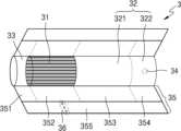
도 9을 참조하면, 에어로졸 생성 물품(3)은 전단 플러그(33)를 더 포함할 수 있다. 전단 플러그(33)는 담배 로드(31)에 있어서, 필터 로드(32)에 반대되는 일 측에 위치할 수 있다. 전단 플러그(33)는 담배 로드(31)가 외부로 이탈하는 것을 방지할 수 있으며, 흡연 중에 담배 로드(31)로부터 액상화된 에어로졸이 에어로졸 생성 장치로 흘러 들어가는 것을 방지할 수 있다.9, the aerosol-generating
필터로드(32)는 제1 세그먼트(321) 및 제2 세그먼트(322)를 포함할 수 있다. 여기에서, 제1 세그먼트(321)는 도 8의 필터 로드(22)의 제1 세그먼트에 대응될 수 있고, 제2 세그먼트(322)는 도 8의 필터 로드(22)의 제3 세그먼트에 대응될 수 있다.The
에어로졸 생성 물품(3)의 직경 및 전체 길이는 도 8의 에어로졸 생성 물품(2)의 직경 및 전체 길이에 대응될 수 있다. 예를 들어, 전단 플러그(33)의 길이는 약 7mm, 담배 로드(31)의 길이는 약 15mm, 제1 세그먼트(321)의 길이는 약 12mm, 제2 세그먼트(322)의 길이는 약 14mm일 수 있으나, 이에 한정되지 않는다.The diameter and overall length of the aerosol-generating
에어로졸 생성 물품(3)은 적어도 하나의 래퍼(35)에 의하여 포장될 수 있다. 래퍼(35)에는 외부 공기가 유입되거나 내부 기체가 유출되는 적어도 하나의 구멍(hole)이 형성될 수 있다. 예를 들어, 제1 래퍼(351)에 의하여 전단 플러그(33)가 포장되고, 제2 래퍼(352)에 의하여 담배 로드(31)가 포장되고, 제3 래퍼(353)에 의하여 제1 세그먼트(321)가 포장되고, 제4 래퍼(354)에 의하여 제2 세그먼트(322)가 포장될 수 있다. 그리고, 제5 래퍼(355)에 의하여 에어로졸 생성 물품(3) 전체가 재포장될 수 있다.The aerosol-generating
또한 제5 래퍼(355)에는 적어도 하나의 천공(36)이 형성될 수 있다. 예를 들어, 천공(36)은 담배 로드(31)를 둘러싸는 영역에 형성될 수 있으나, 이에 제한되지 않는다. 천공(36)은 도 2 및 도 3에 도시된 히터(13)에 의하여 형성된 열을 담배 로드(31)의 내부로 전달하는 역할을 수행할 수 있다.Additionally, at least one
또한 제2 세그먼트(322)에는 적어도 하나의 캡슐(34)이 포함될 수 있다. 여기에서, 캡슐(34)은 향미를 발생시키는 기능을 수행할 수도 있고, 에어로졸을 발생시키는 기능을 수행할 수도 있다. 예를 들어, 캡슐(34)은 향료를 포함하는 액체를 피막으로 감싼 구조일 수 있다. 캡슐(34)은 구형 또는 원통형의 형상을 가질 수 있으나, 이에 제한되지 않는다.Additionally, the
실시 예들은 컴퓨터에 의해 실행되는 프로그램 모듈과 같은 컴퓨터에 의해 실행가능한 명령어를 포함하는 기록 매체의 형태로도 구현될 수 있다. 컴퓨터 판독 가능 매체는 컴퓨터에 의해 액세스될 수 있는 임의의 가용 매체일 수 있고, 휘발성 및 비휘발성 매체, 분리형 및 비분리형 매체를 모두 포함한다. 또한 컴퓨터 판독가능 매체는 컴퓨터 저장 매체 및 통신 매체를 모두 포함할 수 있다. 컴퓨터 저장 매체는 컴퓨터 판독가능 명령어, 데이터 구조, 프로그램 모듈 또는 기타 데이터와 같은 정보의 저장을 위한 임의의 방법 또는 기술로 구현된 휘발성 및 비휘발성, 분리형 및 비분리형 매체를 모두 포함한다. 통신 매체는 전형적으로 컴퓨터 판독가능 명령어, 데이터 구조, 프로그램 모듈과 같은 변조된 데이터 신호의 기타 데이터, 또는 기타 전송 메커니즘을 포함하며, 임의의 정보 전달 매체를 포함한다.Embodiments may also be implemented in the form of a recording medium containing instructions executable by a computer, such as program modules executed by a computer. Computer-readable media can be any available media that can be accessed by a computer and includes both volatile and non-volatile media, removable and non-removable media. Additionally, computer-readable media may include both computer storage media and communication media. Computer storage media includes both volatile and non-volatile, removable and non-removable media implemented in any method or technology for storage of information such as computer-readable instructions, data structures, program modules or other data. Communication media typically includes computer readable instructions, data structures, other data such as program modules, modulated data signals, or other transmission mechanisms, and includes any information delivery medium.
상술한 실시 예들에 대한 설명은 예시적인 것에 불과하며, 당해 기술 분야에서 통상의 지식을 가진 자라면 이로부터 다양한 변형 및 균등한 다른 실시 예가 가능하다는 점을 이해할 것이다. 따라서 발명의 진정한 보호 범위는 첨부된 청구범위에 의해 정해져야 할 것이며, 청구범위에 기재된 내용과 동등한 범위에 있는 모든 차이점은 청구범위에 의해 정해지는 보호 범위에 포함되는 것으로 해석되어야 할 것이다.The description of the above-described embodiments is merely illustrative, and those skilled in the art will understand that various modifications and equivalent other embodiments are possible therefrom. Therefore, the true scope of protection of the invention should be determined by the appended claims, and all differences within the equivalent scope of what is stated in the claims should be interpreted as being included in the scope of protection determined by the claims.
1: 에어로졸 생성 장치11; 배터리
12; 프로세서13: 히터
15: 수용공간100: 하우징
110: 홀120: 가이드
200: 커버300: 공기 유입구
400: 유지부410: 제1 유지부재
420: 제2 유지부재500: 탄성부재1:
12; Processor 13: Heater
15: Accommodation space 100: Housing
110: Hall 120: Guide
200: Cover 300: Air inlet
400: holding part 410: first holding member
420: second holding member 500: elastic member
Claims (12)
Translated fromKorean에어로졸 생성 물품이 삽입되는 홀(Hole)을 포함하는 하우징;
상기 홀을 개방하는 제1 위치와 상기 홀을 폐쇄하는 제2 위치 사이에서 이동 가능하게 상기 하우징에 배치된 커버;
상기 홀로부터 이격 배치되고, 상기 커버의 이동을 가이드 하도록 상기 하우징에 배치된 가이드;
상기 커버에 연결되고, 상기 커버가 상기 제1 위치와 상기 제2 위치를 벗어난 경우 상기 커버에 탄성력을 제공하여 상기 커버의 이동을 안내하는 탄성부재; 및
상기 커버를 상기 제1 위치 또는 상기 제2 위치에 유지하고, 상기 커버가 이동하는 경로 상에 배치된 유지부;를 포함하고,
상기 가이드는 상기 하우징의 일면에 마련된 돌기이며,
상기 커버는 상기 가이드의 돌기에 삽입되는 홈을 포함하고,
상기 유지부는 상기 커버의 양 측에 배치되는 제1 유지부재, 및 상기 가이드의 양 측에 배치되어 상기 제1 위치 또는 상기 제2 위치에서 상기 제1 유지부재와 결합하는 제2 유지부재를 포함하며,
상기 커버가 상기 제1 유지부재 및 상기 제2 유지부재 사이의 인력이 미치는 영역 내에 위치할 때, 상기 제1 유지부재 및 상기 제2 유지부재는 서로 결합함으로써 상기 커버를 상기 제1 위치 또는 상기 제2 위치로 유지하는, 에어로졸 생성 장치.In the aerosol generating device,
A housing including a hole into which an aerosol-generating article is inserted;
a cover disposed on the housing to be movable between a first position opening the hole and a second position closing the hole;
a guide spaced apart from the hole and disposed on the housing to guide movement of the cover;
an elastic member connected to the cover and providing elastic force to the cover to guide movement of the cover when the cover deviates from the first position and the second position; and
A holding part that maintains the cover in the first position or the second position and is disposed on a path along which the cover moves,
The guide is a protrusion provided on one surface of the housing,
The cover includes a groove inserted into the protrusion of the guide,
The holding part includes a first holding member disposed on both sides of the cover, and a second holding member disposed on both sides of the guide and coupled to the first holding member at the first position or the second position. ,
When the cover is located in the area where the attractive force between the first holding member and the second holding member is applied, the first holding member and the second holding member engage with each other to move the cover to the first position or the second holding member. Aerosol generating device, held in two positions.
상기 가이드는,
상기 홀로부터 제1 방향으로 이격되고, 상기 제1 방향을 가로지르는 제2 방향으로 연장되는, 에어로졸 생성 장치.According to paragraph 1,
The guide is:
An aerosol generating device spaced apart from the hole in a first direction and extending in a second direction transverse to the first direction.
상기 가이드 중 적어도 일부는 상기 홀에 대응되는 제1 영역에 위치하고, 상기 가이드 중 나머지 일부는 상기 홀에 대응되지 않는 제2 영역에 위치하는, 에어로졸 생성 장치.According to paragraph 1,
At least some of the guides are located in a first area corresponding to the hole, and the remaining part of the guides are located in a second area that does not correspond to the hole.
상기 가이드와 이격된 공기 유입구;를 더 포함하고,
상기 공기 유입구는,
공기가 상기 에어로졸 생성 장치의 내부에서 이동하는 경로인 기류 통로와 연결되는, 에어로졸 생성 장치.According to paragraph 1,
It further includes an air inlet spaced apart from the guide,
The air inlet is,
An aerosol generating device connected to an airflow passage, which is a path through which air moves within the aerosol generating device.
상기 공기 유입구는 상기 홀의 둘레에 위치하는, 에어로졸 생성 장치.According to clause 4,
An aerosol generating device, wherein the air inlet is located around the hole.
상기 탄성부재는 상기 커버가 상기 제1 위치 및 상기 제2 위치의 사이의 임계위치를 지나는 지점에서 상기 커버에 탄성력을 제공함으로써 상기 커버를 이동시키는, 에어로졸 생성 장치.According to paragraph 1,
wherein the elastic member moves the cover by providing an elastic force to the cover at a point where the cover passes a critical position between the first position and the second position.
상기 에어로졸 생성 물품을 가열하는 히터;
상기 히터에 전력을 공급하는 배터리; 및
상기 배터리로부터 상기 히터에 공급되는 전력을 제어하는 프로세서;를 더 포함하고,
상기 프로세서는, 상기 커버가 상기 홀을 개방하였는지 여부에 기초하여 상기 배터리로부터 상기 히터로의 전력 공급을 제어하는, 에어로졸 생성 장치.According to paragraph 1,
a heater for heating the aerosol-generating article;
a battery supplying power to the heater; and
It further includes a processor that controls power supplied from the battery to the heater,
The processor controls power supply from the battery to the heater based on whether the cover opens the hole.
상기 프로세서는,
상기 커버가 상기 제1 위치에 위치할 때, 상기 배터리로부터 상기 히터로 전력 공급을 허용하는, 에어로졸 생성 장치.According to clause 10,
The processor,
Allowing power supply from the battery to the heater when the cover is positioned in the first position.
상기 프로세서는,
상기 커버가 상기 제1 위치에 위치하지 않을 때, 상기 배터리로부터 상기 히터로 전력 공급을 차단하는, 에어로졸 생성 장치.
According to clause 10,
The processor,
Cutting off power supply from the battery to the heater when the cover is not positioned in the first position.
Priority Applications (12)
| Application Number | Priority Date | Filing Date | Title |
|---|---|---|---|
| KR1020210095617AKR102681871B1 (en) | 2021-07-21 | 2021-07-21 | Aerosol generating device |
| EP23217706.3AEP4335314A3 (en) | 2021-07-21 | 2022-07-21 | Aerosol generating device |
| JP2023554062AJP7747768B2 (en) | 2021-07-21 | 2022-07-21 | Aerosol Generator |
| CA3212605ACA3212605A1 (en) | 2021-07-21 | 2022-07-21 | Aerosol generating device |
| CN202280017987.0ACN116940255A (en) | 2021-07-21 | 2022-07-21 | aerosol generating device |
| PCT/KR2022/010676WO2023003377A1 (en) | 2021-07-21 | 2022-07-21 | Aerosol generating device |
| CN202410306159.XACN118044650A (en) | 2021-07-21 | 2022-07-21 | Aerosol generating device |
| EP22846247.9AEP4287875A4 (en) | 2021-07-21 | 2022-07-21 | AEROSOL GENERATING DEVICE |
| US18/279,252US20240138475A1 (en) | 2021-07-21 | 2022-07-21 | Aerosol generating device |
| KR1020230085972AKR102624138B1 (en) | 2021-07-21 | 2023-07-03 | Aerosol generating device |
| JP2023189321AJP2024027115A (en) | 2021-07-21 | 2023-11-06 | Aerosol generating device |
| US18/529,054US20240099390A1 (en) | 2021-07-21 | 2023-12-05 | Aerosol generating device |
Applications Claiming Priority (1)
| Application Number | Priority Date | Filing Date | Title |
|---|---|---|---|
| KR1020210095617AKR102681871B1 (en) | 2021-07-21 | 2021-07-21 | Aerosol generating device |
Related Child Applications (1)
| Application Number | Title | Priority Date | Filing Date |
|---|---|---|---|
| KR1020230085972ADivisionKR102624138B1 (en) | 2021-07-21 | 2023-07-03 | Aerosol generating device |
Publications (2)
| Publication Number | Publication Date |
|---|---|
| KR20230014366A KR20230014366A (en) | 2023-01-30 |
| KR102681871B1true KR102681871B1 (en) | 2024-07-04 |
Family
ID=84979277
Family Applications (2)
| Application Number | Title | Priority Date | Filing Date |
|---|---|---|---|
| KR1020210095617AActiveKR102681871B1 (en) | 2021-07-21 | 2021-07-21 | Aerosol generating device |
| KR1020230085972AActiveKR102624138B1 (en) | 2021-07-21 | 2023-07-03 | Aerosol generating device |
Family Applications After (1)
| Application Number | Title | Priority Date | Filing Date |
|---|---|---|---|
| KR1020230085972AActiveKR102624138B1 (en) | 2021-07-21 | 2023-07-03 | Aerosol generating device |
Country Status (7)
| Country | Link |
|---|---|
| US (2) | US20240138475A1 (en) |
| EP (2) | EP4287875A4 (en) |
| JP (2) | JP7747768B2 (en) |
| KR (2) | KR102681871B1 (en) |
| CN (2) | CN116940255A (en) |
| CA (1) | CA3212605A1 (en) |
| WO (1) | WO2023003377A1 (en) |
Families Citing this family (3)
| Publication number | Priority date | Publication date | Assignee | Title |
|---|---|---|---|---|
| JP2025516918A (en)* | 2022-06-16 | 2025-05-30 | ケーティー アンド ジー コーポレイション | Aerosol generating device and method of operation thereof |
| CN220192222U (en)* | 2023-02-21 | 2023-12-19 | 深圳麦时科技有限公司 | aerosol generating device |
| KR20250122224A (en)* | 2024-02-06 | 2025-08-13 | 주식회사 케이티앤지 | Aerosol generating device comprising an switch |
Citations (3)
| Publication number | Priority date | Publication date | Assignee | Title |
|---|---|---|---|---|
| CN111280486A (en)* | 2018-11-21 | 2020-06-16 | 湖南中烟工业有限责任公司 | Magnetic repulsion damping structure and low-temperature smoking set with same |
| WO2020182755A1 (en)* | 2019-03-11 | 2020-09-17 | Nicoventures Trading Limited | Aerosol provision device |
| WO2020225105A1 (en)* | 2019-05-03 | 2020-11-12 | Jt International S.A. | Aerosol generation device having a moveable closure with a detector |
Family Cites Families (18)
| Publication number | Priority date | Publication date | Assignee | Title |
|---|---|---|---|---|
| WO2016023175A1 (en)* | 2014-08-12 | 2016-02-18 | 刘水根 | Tobacco evaporator |
| TW201938051A (en)* | 2018-03-09 | 2019-10-01 | 瑞士商菲利浦莫里斯製品股份有限公司 | An aerosol-generating device comprising a cover element |
| CN208096026U (en) | 2018-04-09 | 2018-11-16 | 深圳市合元科技有限公司 | A kind of cover sliding device and electronic smoking set |
| CN208425523U (en) | 2018-06-25 | 2019-01-25 | 惠州市吉瑞科技有限公司深圳分公司 | Flue-cured tobacco electronic cigarette with protection cap |
| KR102203852B1 (en)* | 2018-11-16 | 2021-01-15 | 주식회사 케이티앤지 | Apparatus and system for generating aerosols |
| JP2020156382A (en) | 2019-03-26 | 2020-10-01 | 日本電産コパル株式会社 | Case component for cigarette case and cigarette case |
| TWI789584B (en)* | 2019-05-03 | 2023-01-11 | 瑞士商傑太日煙國際股份有限公司(瑞士) | Aerosol generation device with closure and method of operating aerosol generation device |
| CN110179162A (en) | 2019-06-05 | 2019-08-30 | 上海新型烟草制品研究院有限公司 | A kind of aerosol generating device |
| GB201908194D0 (en) | 2019-06-07 | 2019-07-24 | Nicoventures Trading Ltd | Aerosol provision device |
| KR102395183B1 (en)* | 2019-07-23 | 2022-05-06 | 주식회사 케이티앤지 | Aerosol generating device |
| EP4009818A1 (en)* | 2019-08-08 | 2022-06-15 | JT International SA | Aerosol generation device having closure with rigid biasing element |
| CN210445698U (en) | 2019-08-09 | 2020-05-05 | 深圳市讴可电子科技有限公司 | Electronic cigarette |
| EP4044855B1 (en)* | 2019-10-17 | 2023-11-29 | Philip Morris Products S.A. | Charger and aerosol-generating system with improved closing means |
| CN211211450U (en)* | 2019-10-30 | 2020-08-11 | 深圳市合元科技有限公司 | Aerosol generating device |
| KR102423896B1 (en)* | 2019-11-22 | 2022-07-21 | 주식회사 케이티앤지 | Aerosol generating device |
| KR102355185B1 (en)* | 2019-12-19 | 2022-01-25 | 주식회사 이엠텍 | Aerosol generator |
| CN213604383U (en)* | 2020-09-08 | 2021-07-06 | 深圳市合元科技有限公司 | Door cover mechanism and aerosol generating device |
| CN112914160A (en)* | 2021-03-25 | 2021-06-08 | 陈玉水 | Electron cigarette subassembly |
- 2021
- 2021-07-21KRKR1020210095617Apatent/KR102681871B1/enactiveActive
- 2022
- 2022-07-21CNCN202280017987.0Apatent/CN116940255A/enactivePending
- 2022-07-21EPEP22846247.9Apatent/EP4287875A4/enactivePending
- 2022-07-21WOPCT/KR2022/010676patent/WO2023003377A1/ennot_activeCeased
- 2022-07-21CNCN202410306159.XApatent/CN118044650A/enactivePending
- 2022-07-21JPJP2023554062Apatent/JP7747768B2/enactiveActive
- 2022-07-21CACA3212605Apatent/CA3212605A1/enactivePending
- 2022-07-21USUS18/279,252patent/US20240138475A1/enactivePending
- 2022-07-21EPEP23217706.3Apatent/EP4335314A3/enactivePending
- 2023
- 2023-07-03KRKR1020230085972Apatent/KR102624138B1/enactiveActive
- 2023-11-06JPJP2023189321Apatent/JP2024027115A/enactivePending
- 2023-12-05USUS18/529,054patent/US20240099390A1/enactivePending
Patent Citations (3)
| Publication number | Priority date | Publication date | Assignee | Title |
|---|---|---|---|---|
| CN111280486A (en)* | 2018-11-21 | 2020-06-16 | 湖南中烟工业有限责任公司 | Magnetic repulsion damping structure and low-temperature smoking set with same |
| WO2020182755A1 (en)* | 2019-03-11 | 2020-09-17 | Nicoventures Trading Limited | Aerosol provision device |
| WO2020225105A1 (en)* | 2019-05-03 | 2020-11-12 | Jt International S.A. | Aerosol generation device having a moveable closure with a detector |
Also Published As
| Publication number | Publication date |
|---|---|
| EP4335314A3 (en) | 2024-05-15 |
| EP4287875A1 (en) | 2023-12-13 |
| KR20230014366A (en) | 2023-01-30 |
| JP2024027115A (en) | 2024-02-29 |
| KR102624138B1 (en) | 2024-01-11 |
| EP4287875A4 (en) | 2024-05-15 |
| JP2024509225A (en) | 2024-02-29 |
| CA3212605A1 (en) | 2023-01-26 |
| EP4335314A2 (en) | 2024-03-13 |
| CN118044650A (en) | 2024-05-17 |
| CN116940255A (en) | 2023-10-24 |
| JP7747768B2 (en) | 2025-10-01 |
| US20240099390A1 (en) | 2024-03-28 |
| KR20230107176A (en) | 2023-07-14 |
| WO2023003377A1 (en) | 2023-01-26 |
| US20240138475A1 (en) | 2024-05-02 |
Similar Documents
| Publication | Publication Date | Title |
|---|---|---|
| KR102624138B1 (en) | Aerosol generating device | |
| KR20230115452A (en) | Aerosol generating divice | |
| KR102600665B1 (en) | Aerosol generating apparatus for sensing aerosol generating article and operation method thereof | |
| JP7750994B2 (en) | Aerosol generating device and method of operation thereof | |
| KR102684537B1 (en) | Aerosol generating device | |
| US20240148075A1 (en) | Method and device for processing user input during battery charging | |
| KR20230173564A (en) | Aerosol generating device | |
| KR20230068948A (en) | Aerosol generating device and operating method thereof | |
| KR20230083976A (en) | Heating structure and aerosol generating device and system comprising the same | |
| RU2827973C2 (en) | Aerosol generator | |
| RU2834334C2 (en) | Aerosol generator | |
| US20240423268A1 (en) | Aerosol generating device | |
| KR102755958B1 (en) | Cover structure and aerosol generating device | |
| US20240334986A1 (en) | Aerosol generating device capable of outputting sound | |
| KR20240082969A (en) | Aerosol generating article recognition unit and aerosol generating device including the same | |
| US20240315340A1 (en) | Aerosol generating device and aerosol generating system | |
| EP4516125A1 (en) | Aerosol-generating article and aerosol-generating system | |
| JP7698132B2 (en) | Aerosol Generator | |
| US20240284984A1 (en) | Aerosol generating device | |
| US20240196985A1 (en) | Aerosol generating device and operating method thereof | |
| KR20240044117A (en) | Heating assembly and aerosol generating device comprising the same | |
| KR20240028268A (en) | Aerosol generating device | |
| KR20240107528A (en) | Aerosol generating device | |
| KR20240031767A (en) | Aerosol generating device and aerosol generating system comprising the same | |
| KR20240021086A (en) | Vaporizer for aerosol generating device and aerosol generating device comprising the same |
Legal Events
| Date | Code | Title | Description |
|---|---|---|---|
| PA0109 | Patent application | St.27 status event code:A-0-1-A10-A12-nap-PA0109 | |
| PA0201 | Request for examination | St.27 status event code:A-1-2-D10-D11-exm-PA0201 | |
| PG1501 | Laying open of application | St.27 status event code:A-1-1-Q10-Q12-nap-PG1501 | |
| E902 | Notification of reason for refusal | ||
| PE0902 | Notice of grounds for rejection | St.27 status event code:A-1-2-D10-D21-exm-PE0902 | |
| PA0107 | Divisional application | St.27 status event code:A-0-1-A10-A18-div-PA0107 St.27 status event code:A-0-1-A10-A16-div-PA0107 | |
| AMND | Amendment | ||
| E13-X000 | Pre-grant limitation requested | St.27 status event code:A-2-3-E10-E13-lim-X000 | |
| P11-X000 | Amendment of application requested | St.27 status event code:A-2-2-P10-P11-nap-X000 | |
| P13-X000 | Application amended | St.27 status event code:A-2-2-P10-P13-nap-X000 | |
| E601 | Decision to refuse application | ||
| PE0601 | Decision on rejection of patent | St.27 status event code:N-2-6-B10-B15-exm-PE0601 | |
| AMND | Amendment | ||
| E13-X000 | Pre-grant limitation requested | St.27 status event code:A-2-3-E10-E13-lim-X000 | |
| P11-X000 | Amendment of application requested | St.27 status event code:A-2-2-P10-P11-nap-X000 | |
| P13-X000 | Application amended | St.27 status event code:A-2-2-P10-P13-nap-X000 | |
| PX0901 | Re-examination | St.27 status event code:A-2-3-E10-E12-rex-PX0901 | |
| PX0701 | Decision of registration after re-examination | St.27 status event code:A-3-4-F10-F13-rex-PX0701 | |
| X701 | Decision to grant (after re-examination) | ||
| PR0701 | Registration of establishment | St.27 status event code:A-2-4-F10-F11-exm-PR0701 | |
| PR1002 | Payment of registration fee | St.27 status event code:A-2-2-U10-U11-oth-PR1002 Fee payment year number:1 | |
| PG1601 | Publication of registration | St.27 status event code:A-4-4-Q10-Q13-nap-PG1601 | |
| R18-X000 | Changes to party contact information recorded | St.27 status event code:A-5-5-R10-R18-oth-X000 |