KR102677694B1 - Mold supporting unit and apparatus for manufacturing micro structure including the mold supporting unit - Google Patents
Mold supporting unit and apparatus for manufacturing micro structure including the mold supporting unitDownload PDFInfo
- Publication number
- KR102677694B1 KR102677694B1KR1020210049444AKR20210049444AKR102677694B1KR 102677694 B1KR102677694 B1KR 102677694B1KR 1020210049444 AKR1020210049444 AKR 1020210049444AKR 20210049444 AKR20210049444 AKR 20210049444AKR 102677694 B1KR102677694 B1KR 102677694B1
- Authority
- KR
- South Korea
- Prior art keywords
- support
- mold
- unit
- angle
- area
- Prior art date
- Legal status (The legal status is an assumption and is not a legal conclusion. Google has not performed a legal analysis and makes no representation as to the accuracy of the status listed.)
- Active
Links
- 238000004519manufacturing processMethods0.000titleclaimsabstractdescription48
- 239000000203mixtureSubstances0.000claimsdescription32
- 230000000149penetrating effectEffects0.000claimsdescription2
- -1poly(α-hydroxyacid)Polymers0.000description30
- 238000010586diagramMethods0.000description25
- 239000003814drugSubstances0.000description22
- 229940079593drugDrugs0.000description15
- 238000000034methodMethods0.000description7
- 230000004308accommodationEffects0.000description5
- 108090000623proteins and genesProteins0.000description5
- 102000004169proteins and genesHuman genes0.000description5
- 239000004480active ingredientSubstances0.000description4
- 238000002347injectionMethods0.000description4
- 239000007924injectionSubstances0.000description4
- 239000005014poly(hydroxyalkanoate)Substances0.000description4
- 229920000903polyhydroxyalkanoatePolymers0.000description4
- 230000008569processEffects0.000description4
- 108090000765processed proteins & peptidesProteins0.000description4
- 239000000126substanceSubstances0.000description4
- 229940124597therapeutic agentDrugs0.000description4
- 239000004721Polyphenylene oxideSubstances0.000description3
- 230000000052comparative effectEffects0.000description3
- 239000000463materialSubstances0.000description3
- 229920000728polyesterPolymers0.000description3
- 229920000570polyetherPolymers0.000description3
- 229920000642polymerPolymers0.000description3
- KIUKXJAPPMFGSW-DNGZLQJQSA-N(2S,3S,4S,5R,6R)-6-[(2S,3R,4R,5S,6R)-3-Acetamido-2-[(2S,3S,4R,5R,6R)-6-[(2R,3R,4R,5S,6R)-3-acetamido-2,5-dihydroxy-6-(hydroxymethyl)oxan-4-yl]oxy-2-carboxy-4,5-dihydroxyoxan-3-yl]oxy-5-hydroxy-6-(hydroxymethyl)oxan-4-yl]oxy-3,4,5-trihydroxyoxane-2-carboxylic acidChemical compoundCC(=O)N[C@H]1[C@H](O)O[C@H](CO)[C@@H](O)[C@@H]1O[C@H]1[C@H](O)[C@@H](O)[C@H](O[C@H]2[C@@H]([C@@H](O[C@H]3[C@@H]([C@@H](O)[C@H](O)[C@H](O3)C(O)=O)O)[C@H](O)[C@@H](CO)O2)NC(C)=O)[C@@H](C(O)=O)O1KIUKXJAPPMFGSW-DNGZLQJQSA-N0.000description2
- HPMGFDVTYHWBAG-UHFFFAOYSA-N3-hydroxyhexanoic acidChemical compoundCCCC(O)CC(O)=OHPMGFDVTYHWBAG-UHFFFAOYSA-N0.000description2
- ALRHLSYJTWAHJZ-UHFFFAOYSA-M3-hydroxypropionateChemical compoundOCCC([O-])=OALRHLSYJTWAHJZ-UHFFFAOYSA-M0.000description2
- FHVDTGUDJYJELY-UHFFFAOYSA-N6-{[2-carboxy-4,5-dihydroxy-6-(phosphanyloxy)oxan-3-yl]oxy}-4,5-dihydroxy-3-phosphanyloxane-2-carboxylic acidChemical compoundO1C(C(O)=O)C(P)C(O)C(O)C1OC1C(C(O)=O)OC(OP)C(O)C1OFHVDTGUDJYJELY-UHFFFAOYSA-N0.000description2
- 229920001661ChitosanPolymers0.000description2
- 102400000739CorticotropinHuman genes0.000description2
- 101800000414CorticotropinProteins0.000description2
- 229920002307DextranPolymers0.000description2
- 108010066486EGF Family of ProteinsProteins0.000description2
- 102000018386EGF Family of ProteinsHuman genes0.000description2
- JOYRKODLDBILNP-UHFFFAOYSA-NEthyl urethaneChemical compoundCCOC(N)=OJOYRKODLDBILNP-UHFFFAOYSA-N0.000description2
- 229920000219Ethylene vinyl alcoholPolymers0.000description2
- 108700012941GNRH1Proteins0.000description2
- 229920002527GlycogenPolymers0.000description2
- AEMRFAOFKBGASW-UHFFFAOYSA-NGlycolic acidPolymersOCC(O)=OAEMRFAOFKBGASW-UHFFFAOYSA-N0.000description2
- 239000000579Gonadotropin-Releasing HormoneSubstances0.000description2
- 102000018997Growth HormoneHuman genes0.000description2
- 108010051696Growth HormoneProteins0.000description2
- HTTJABKRGRZYRN-UHFFFAOYSA-NHeparinChemical compoundOC1C(NC(=O)C)C(O)OC(COS(O)(=O)=O)C1OC1C(OS(O)(=O)=O)C(O)C(OC2C(C(OS(O)(=O)=O)C(OC3C(C(O)C(O)C(O3)C(O)=O)OS(O)(=O)=O)C(CO)O2)NS(O)(=O)=O)C(C(O)=O)O1HTTJABKRGRZYRN-UHFFFAOYSA-N0.000description2
- 101000599951Homo sapiens Insulin-like growth factor IProteins0.000description2
- 102100037852Insulin-like growth factor IHuman genes0.000description2
- 229920001202InulinPolymers0.000description2
- OUYCCCASQSFEME-QMMMGPOBSA-NL-tyrosineChemical compoundOC(=O)[C@@H](N)CC1=CC=C(O)C=C1OUYCCCASQSFEME-QMMMGPOBSA-N0.000description2
- MUBZPKHOEPUJKR-UHFFFAOYSA-NOxalic acidChemical compoundOC(=O)C(O)=OMUBZPKHOEPUJKR-UHFFFAOYSA-N0.000description2
- 208000002193PainDiseases0.000description2
- 229920002732PolyanhydridePolymers0.000description2
- 229920000954PolyglycolidePolymers0.000description2
- 229920001710PolyorthoesterPolymers0.000description2
- 229920002472StarchPolymers0.000description2
- 108060008682Tumor Necrosis FactorProteins0.000description2
- 229940072056alginateDrugs0.000description2
- 229920000615alginic acidPolymers0.000description2
- 235000010443alginic acidNutrition0.000description2
- 230000008901benefitEffects0.000description2
- 238000005266castingMethods0.000description2
- 229920002678cellulosePolymers0.000description2
- 239000001913celluloseSubstances0.000description2
- IDLFZVILOHSSID-OVLDLUHVSA-NcorticotropinChemical compoundC([C@@H](C(=O)N[C@@H](CO)C(=O)N[C@@H](CCSC)C(=O)N[C@@H](CCC(O)=O)C(=O)N[C@@H](CC=1NC=NC=1)C(=O)N[C@@H](CC=1C=CC=CC=1)C(=O)N[C@@H](CCCNC(N)=N)C(=O)N[C@@H](CC=1C2=CC=CC=C2NC=1)C(=O)NCC(=O)N[C@@H](CCCCN)C(=O)N1[C@@H](CCC1)C(=O)N[C@@H](C(C)C)C(=O)NCC(=O)N[C@@H](CCCCN)C(=O)N[C@@H](CCCCN)C(=O)N[C@@H](CCCNC(N)=N)C(=O)N[C@@H](CCCNC(N)=N)C(=O)N1[C@@H](CCC1)C(=O)N[C@@H](C(C)C)C(=O)N[C@@H](CCCCN)C(=O)N[C@@H](C(C)C)C(=O)N[C@@H](CC=1C=CC(O)=CC=1)C(=O)N1[C@@H](CCC1)C(=O)N[C@@H](CC(N)=O)C(=O)NCC(=O)N[C@@H](C)C(=O)N[C@@H](CCC(O)=O)C(=O)N[C@@H](CC(O)=O)C(=O)N[C@@H](CCC(O)=O)C(=O)N[C@@H](CO)C(=O)N[C@@H](C)C(=O)N[C@@H](CCC(O)=O)C(=O)N[C@@H](C)C(=O)N[C@@H](CC=1C=CC=CC=1)C(=O)N1[C@@H](CCC1)C(=O)N[C@@H](CC(C)C)C(=O)N[C@@H](CCC(O)=O)C(=O)N[C@@H](CC=1C=CC=CC=1)C(O)=O)NC(=O)[C@@H](N)CO)C1=CC=C(O)C=C1IDLFZVILOHSSID-OVLDLUHVSA-N0.000description2
- 229960000258corticotropinDrugs0.000description2
- 230000007423decreaseEffects0.000description2
- PEASPLKKXBYDKL-FXEVSJAOSA-NenfuvirtideChemical compoundC([C@@H](C(=O)N[C@@H](CO)C(=O)N[C@@H](CC(C)C)C(=O)N[C@@H]([C@@H](C)CC)C(=O)N[C@@H](CCC(O)=O)C(=O)N[C@@H](CCC(O)=O)C(=O)N[C@@H](CO)C(=O)N[C@@H](CCC(N)=O)C(=O)N[C@@H](CC(N)=O)C(=O)N[C@@H](CCC(N)=O)C(=O)N[C@@H](CCC(N)=O)C(=O)N[C@@H](CCC(O)=O)C(=O)N[C@@H](CCCCN)C(=O)N[C@@H](CC(N)=O)C(=O)N[C@@H](CCC(O)=O)C(=O)N[C@@H](CCC(N)=O)C(=O)N[C@@H](CCC(O)=O)C(=O)N[C@@H](CC(C)C)C(=O)N[C@@H](CC(C)C)C(=O)N[C@@H](CCC(O)=O)C(=O)N[C@@H](CC(C)C)C(=O)N[C@@H](CC(O)=O)C(=O)N[C@@H](CCCCN)C(=O)N[C@@H](CC=1C2=CC=CC=C2NC=1)C(=O)N[C@@H](C)C(=O)N[C@@H](CO)C(=O)N[C@@H](CC(C)C)C(=O)N[C@@H](CC=1C2=CC=CC=C2NC=1)C(=O)N[C@@H](CC(N)=O)C(=O)N[C@@H](CC=1C2=CC=CC=C2NC=1)C(=O)N[C@@H](CC=1C=CC=CC=1)C(N)=O)NC(=O)[C@@H](NC(=O)[C@H](CC(C)C)NC(=O)[C@H](CO)NC(=O)[C@@H](NC(=O)[C@H](CC=1C=CC(O)=CC=1)NC(C)=O)[C@@H](C)O)[C@@H](C)CC)C1=CN=CN1PEASPLKKXBYDKL-FXEVSJAOSA-N0.000description2
- 150000002148estersChemical class0.000description2
- 230000014509gene expressionEffects0.000description2
- 229940096919glycogenDrugs0.000description2
- 239000000122growth hormoneSubstances0.000description2
- 229920000669heparinPolymers0.000description2
- 229960002897heparinDrugs0.000description2
- 229940088597hormoneDrugs0.000description2
- 239000005556hormoneSubstances0.000description2
- 229920002674hyaluronanPolymers0.000description2
- 229960003160hyaluronic acidDrugs0.000description2
- NOESYZHRGYRDHS-UHFFFAOYSA-NinsulinChemical compoundN1C(=O)C(NC(=O)C(CCC(N)=O)NC(=O)C(CCC(O)=O)NC(=O)C(C(C)C)NC(=O)C(NC(=O)CN)C(C)CC)CSSCC(C(NC(CO)C(=O)NC(CC(C)C)C(=O)NC(CC=2C=CC(O)=CC=2)C(=O)NC(CCC(N)=O)C(=O)NC(CC(C)C)C(=O)NC(CCC(O)=O)C(=O)NC(CC(N)=O)C(=O)NC(CC=2C=CC(O)=CC=2)C(=O)NC(CSSCC(NC(=O)C(C(C)C)NC(=O)C(CC(C)C)NC(=O)C(CC=2C=CC(O)=CC=2)NC(=O)C(CC(C)C)NC(=O)C(C)NC(=O)C(CCC(O)=O)NC(=O)C(C(C)C)NC(=O)C(CC(C)C)NC(=O)C(CC=2NC=NC=2)NC(=O)C(CO)NC(=O)CNC2=O)C(=O)NCC(=O)NC(CCC(O)=O)C(=O)NC(CCCNC(N)=N)C(=O)NCC(=O)NC(CC=3C=CC=CC=3)C(=O)NC(CC=3C=CC=CC=3)C(=O)NC(CC=3C=CC(O)=CC=3)C(=O)NC(C(C)O)C(=O)N3C(CCC3)C(=O)NC(CCCCN)C(=O)NC(C)C(O)=O)C(=O)NC(CC(N)=O)C(O)=O)=O)NC(=O)C(C(C)CC)NC(=O)C(CO)NC(=O)C(C(C)O)NC(=O)C1CSSCC2NC(=O)C(CC(C)C)NC(=O)C(NC(=O)C(CCC(N)=O)NC(=O)C(CC(N)=O)NC(=O)C(NC(=O)C(N)CC=1C=CC=CC=1)C(C)C)CC1=CN=CN1NOESYZHRGYRDHS-UHFFFAOYSA-N0.000description2
- JYJIGFIDKWBXDU-MNNPPOADSA-NinulinChemical compoundO[C@H]1[C@H](O)[C@@H](CO)O[C@@]1(CO)OC[C@]1(OC[C@]2(OC[C@]3(OC[C@]4(OC[C@]5(OC[C@]6(OC[C@]7(OC[C@]8(OC[C@]9(OC[C@]%10(OC[C@]%11(OC[C@]%12(OC[C@]%13(OC[C@]%14(OC[C@]%15(OC[C@]%16(OC[C@]%17(OC[C@]%18(OC[C@]%19(OC[C@]%20(OC[C@]%21(OC[C@]%22(OC[C@]%23(OC[C@]%24(OC[C@]%25(OC[C@]%26(OC[C@]%27(OC[C@]%28(OC[C@]%29(OC[C@]%30(OC[C@]%31(OC[C@]%32(OC[C@]%33(OC[C@]%34(OC[C@]%35(OC[C@]%36(O[C@@H]%37[C@@H]([C@@H](O)[C@H](O)[C@@H](CO)O%37)O)[C@H]([C@H](O)[C@@H](CO)O%36)O)[C@H]([C@H](O)[C@@H](CO)O%35)O)[C@H]([C@H](O)[C@@H](CO)O%34)O)[C@H]([C@H](O)[C@@H](CO)O%33)O)[C@H]([C@H](O)[C@@H](CO)O%32)O)[C@H]([C@H](O)[C@@H](CO)O%31)O)[C@H]([C@H](O)[C@@H](CO)O%30)O)[C@H]([C@H](O)[C@@H](CO)O%29)O)[C@H]([C@H](O)[C@@H](CO)O%28)O)[C@H]([C@H](O)[C@@H](CO)O%27)O)[C@H]([C@H](O)[C@@H](CO)O%26)O)[C@H]([C@H](O)[C@@H](CO)O%25)O)[C@H]([C@H](O)[C@@H](CO)O%24)O)[C@H]([C@H](O)[C@@H](CO)O%23)O)[C@H]([C@H](O)[C@@H](CO)O%22)O)[C@H]([C@H](O)[C@@H](CO)O%21)O)[C@H]([C@H](O)[C@@H](CO)O%20)O)[C@H]([C@H](O)[C@@H](CO)O%19)O)[C@H]([C@H](O)[C@@H](CO)O%18)O)[C@H]([C@H](O)[C@@H](CO)O%17)O)[C@H]([C@H](O)[C@@H](CO)O%16)O)[C@H]([C@H](O)[C@@H](CO)O%15)O)[C@H]([C@H](O)[C@@H](CO)O%14)O)[C@H]([C@H](O)[C@@H](CO)O%13)O)[C@H]([C@H](O)[C@@H](CO)O%12)O)[C@H]([C@H](O)[C@@H](CO)O%11)O)[C@H]([C@H](O)[C@@H](CO)O%10)O)[C@H]([C@H](O)[C@@H](CO)O9)O)[C@H]([C@H](O)[C@@H](CO)O8)O)[C@H]([C@H](O)[C@@H](CO)O7)O)[C@H]([C@H](O)[C@@H](CO)O6)O)[C@H]([C@H](O)[C@@H](CO)O5)O)[C@H]([C@H](O)[C@@H](CO)O4)O)[C@H]([C@H](O)[C@@H](CO)O3)O)[C@H]([C@H](O)[C@@H](CO)O2)O)[C@@H](O)[C@H](O)[C@@H](CO)O1JYJIGFIDKWBXDU-MNNPPOADSA-N0.000description2
- 229940029339inulinDrugs0.000description2
- 229920000520poly(3-hydroxybutyrate-co-3-hydroxyvalerate)Polymers0.000description2
- 229920000071poly(4-hydroxybutyrate)Polymers0.000description2
- 229920001308poly(aminoacid)Polymers0.000description2
- 229920006211poly(glycolic acid-co-trimethylene carbonate)Polymers0.000description2
- 229920000747poly(lactic acid)Polymers0.000description2
- 229920001606poly(lactic acid-co-glycolic acid)Polymers0.000description2
- 239000002745poly(ortho ester)Substances0.000description2
- 229920002463poly(p-dioxanone) polymerPolymers0.000description2
- 229920002627poly(phosphazenes)Polymers0.000description2
- 229920001857poly(tyrosine carbonate)Polymers0.000description2
- 229920000058polyacrylatePolymers0.000description2
- 229920001610polycaprolactonePolymers0.000description2
- 239000004632polycaprolactoneSubstances0.000description2
- 229920000515polycarbonatePolymers0.000description2
- 239000004417polycarbonateSubstances0.000description2
- 229920002721polycyanoacrylatePolymers0.000description2
- 239000000622polydioxanoneSubstances0.000description2
- 229920000166polytrimethylene carbonatePolymers0.000description2
- 239000007787solidSubstances0.000description2
- 239000008107starchSubstances0.000description2
- 235000019698starchNutrition0.000description2
- 229940032147starchDrugs0.000description2
- 102000003390tumor necrosis factorHuman genes0.000description2
- OUYCCCASQSFEME-UHFFFAOYSA-NtyrosineNatural productsOC(=O)C(N)CC1=CC=C(O)C=C1OUYCCCASQSFEME-UHFFFAOYSA-N0.000description2
- 229940070710valerateDrugs0.000description2
- BJFIDCADFRDPIO-DZCXQCEKSA-N(2S)-N-[(2S)-6-amino-1-[(2-amino-2-oxoethyl)amino]-1-oxohexan-2-yl]-1-[[(4R,7S,10S,13S,16S,19R)-19-amino-7-(2-amino-2-oxoethyl)-10-(3-amino-3-oxopropyl)-16-[(4-hydroxyphenyl)methyl]-6,9,12,15,18-pentaoxo-13-(phenylmethyl)-1,2-dithia-5,8,11,14,17-pentazacycloeicos-4-yl]-oxomethyl]-2-pyrrolidinecarboxamideChemical compoundNCCCC[C@@H](C(=O)NCC(N)=O)NC(=O)[C@@H]1CCCN1C(=O)[C@H]1NC(=O)[C@H](CC(N)=O)NC(=O)[C@H](CCC(N)=O)NC(=O)[C@H](CC=2C=CC=CC=2)NC(=O)[C@H](CC=2C=CC(O)=CC=2)NC(=O)[C@@H](N)CSSC1BJFIDCADFRDPIO-DZCXQCEKSA-N0.000description1
- OVVIBUHLQIYUEU-IWIISZHXSA-N(2s)-6-amino-2-[[(2s)-2-[[(2s)-6-amino-2-[[(2s)-1-[(2s)-2-[[(2s,3s)-2-[[(2s)-2-[[(2s)-2-[[(2s)-2-[[(2s)-2-[[2-[[2-[[(2s)-2-amino-3-(4-hydroxyphenyl)propanoyl]amino]acetyl]amino]acetyl]amino]-3-phenylpropanoyl]amino]-4-methylpentanoyl]amino]-5-(diaminomethChemical compoundC([C@@H](C(=O)N[C@@H](CC(C)C)C(=O)N[C@@H](CCCN=C(N)N)C(=O)N[C@@H](CCCN=C(N)N)C(=O)N[C@@H]([C@@H](C)CC)C(=O)N[C@@H](CCCN=C(N)N)C(=O)N1[C@@H](CCC1)C(=O)N[C@@H](CCCCN)C(=O)N[C@@H](CC(C)C)C(=O)N[C@@H](CCCCN)C(O)=O)NC(=O)CNC(=O)CNC(=O)[C@@H](N)CC=1C=CC(O)=CC=1)C1=CC=CC=C1OVVIBUHLQIYUEU-IWIISZHXSA-N0.000description1
- DEQANNDTNATYII-OULOTJBUSA-N(4r,7s,10s,13r,16s,19r)-10-(4-aminobutyl)-19-[[(2r)-2-amino-3-phenylpropanoyl]amino]-16-benzyl-n-[(2r,3r)-1,3-dihydroxybutan-2-yl]-7-[(1r)-1-hydroxyethyl]-13-(1h-indol-3-ylmethyl)-6,9,12,15,18-pentaoxo-1,2-dithia-5,8,11,14,17-pentazacycloicosane-4-carboxaChemical compoundC([C@@H](N)C(=O)N[C@H]1CSSC[C@H](NC(=O)[C@H]([C@@H](C)O)NC(=O)[C@H](CCCCN)NC(=O)[C@@H](CC=2C3=CC=CC=C3NC=2)NC(=O)[C@H](CC=2C=CC=CC=2)NC1=O)C(=O)N[C@H](CO)[C@H](O)C)C1=CC=CC=C1DEQANNDTNATYII-OULOTJBUSA-N0.000description1
- PUDHBTGHUJUUFI-SCTWWAJVSA-N(4r,7s,10s,13r,16s,19r)-10-(4-aminobutyl)-n-[(2s,3r)-1-amino-3-hydroxy-1-oxobutan-2-yl]-19-[[(2r)-2-amino-3-naphthalen-2-ylpropanoyl]amino]-16-[(4-hydroxyphenyl)methyl]-13-(1h-indol-3-ylmethyl)-6,9,12,15,18-pentaoxo-7-propan-2-yl-1,2-dithia-5,8,11,14,17-pChemical compoundC([C@H]1C(=O)N[C@H](CC=2C3=CC=CC=C3NC=2)C(=O)N[C@@H](CCCCN)C(=O)N[C@H](C(N[C@@H](CSSC[C@@H](C(=O)N1)NC(=O)[C@H](N)CC=1C=C2C=CC=CC2=CC=1)C(=O)N[C@@H]([C@@H](C)O)C(N)=O)=O)C(C)C)C1=CC=C(O)C=C1PUDHBTGHUJUUFI-SCTWWAJVSA-N0.000description1
- UHKPXKGJFOKCGG-UHFFFAOYSA-N2-methylprop-1-ene;styreneChemical compoundCC(C)=C.C=CC1=CC=CC=C1.C=CC1=CC=CC=C1UHKPXKGJFOKCGG-UHFFFAOYSA-N0.000description1
- FMHKPLXYWVCLME-UHFFFAOYSA-N4-hydroxy-valeric acidChemical compoundCC(O)CCC(O)=OFMHKPLXYWVCLME-UHFFFAOYSA-N0.000description1
- SJZRECIVHVDYJC-UHFFFAOYSA-N4-hydroxybutyric acidChemical compoundOCCCC(O)=OSJZRECIVHVDYJC-UHFFFAOYSA-N0.000description1
- 239000000275Adrenocorticotropic HormoneSubstances0.000description1
- 102000015081Blood Coagulation FactorsHuman genes0.000description1
- 108010039209Blood Coagulation FactorsProteins0.000description1
- 108010037003BuserelinProteins0.000description1
- 108060001064CalcitoninProteins0.000description1
- 102400000113CalcitoninHuman genes0.000description1
- 208000024172Cardiovascular diseaseDiseases0.000description1
- 239000000055Corticotropin-Releasing HormoneSubstances0.000description1
- PMATZTZNYRCHOR-CGLBZJNRSA-NCyclosporin AChemical compoundCC[C@@H]1NC(=O)[C@H]([C@H](O)[C@H](C)C\C=C\C)N(C)C(=O)[C@H](C(C)C)N(C)C(=O)[C@H](CC(C)C)N(C)C(=O)[C@H](CC(C)C)N(C)C(=O)[C@@H](C)NC(=O)[C@H](C)NC(=O)[C@H](CC(C)C)N(C)C(=O)[C@H](C(C)C)NC(=O)[C@H](CC(C)C)N(C)C(=O)CN(C)C1=OPMATZTZNYRCHOR-CGLBZJNRSA-N0.000description1
- 108010036949CyclosporineProteins0.000description1
- 102000004127CytokinesHuman genes0.000description1
- 108090000695CytokinesProteins0.000description1
- 108010000437Deamino Arginine VasopressinProteins0.000description1
- GJKXGJCSJWBJEZ-XRSSZCMZSA-NDeslorelinChemical compoundCCNC(=O)[C@@H]1CCCN1C(=O)[C@H](CCCN=C(N)N)NC(=O)[C@H](CC(C)C)NC(=O)[C@H](NC(=O)[C@H](CC=1C=CC(O)=CC=1)NC(=O)[C@H](CO)NC(=O)[C@H](CC=1C2=CC=CC=C2NC=1)NC(=O)[C@H](CC=1NC=NC=1)NC(=O)[C@H]1NC(=O)CC1)CC1=CNC2=CC=CC=C12GJKXGJCSJWBJEZ-XRSSZCMZSA-N0.000description1
- 102400000239Dynorphin A(1-13)Human genes0.000description1
- 108010032976EnfuvirtideProteins0.000description1
- 102000004190EnzymesHuman genes0.000description1
- 108090000790EnzymesProteins0.000description1
- 108010056764EptifibatideProteins0.000description1
- 102000003951ErythropoietinHuman genes0.000description1
- 108090000394ErythropoietinProteins0.000description1
- 102400000932Gonadoliberin-1Human genes0.000description1
- 108010069236GoserelinProteins0.000description1
- BLCLNMBMMGCOAS-URPVMXJPSA-NGoserelinChemical compoundC([C@@H](C(=O)N[C@H](COC(C)(C)C)C(=O)N[C@@H](CC(C)C)C(=O)N[C@@H](CCCN=C(N)N)C(=O)N1[C@@H](CCC1)C(=O)NNC(N)=O)NC(=O)[C@H](CO)NC(=O)[C@H](CC=1C2=CC=CC=C2NC=1)NC(=O)[C@H](CC=1NC=NC=1)NC(=O)[C@H]1NC(=O)CC1)C1=CC=C(O)C=C1BLCLNMBMMGCOAS-URPVMXJPSA-N0.000description1
- 101500026183Homo sapiens Gonadoliberin-1Proteins0.000description1
- 102000004877InsulinHuman genes0.000description1
- 108090001061InsulinProteins0.000description1
- 102000006992Interferon-alphaHuman genes0.000description1
- 108010047761Interferon-alphaProteins0.000description1
- 102000003996Interferon-betaHuman genes0.000description1
- 108090000467Interferon-betaProteins0.000description1
- 102000008070Interferon-gammaHuman genes0.000description1
- 108010074328Interferon-gammaProteins0.000description1
- 102000003777Interleukin-1 betaHuman genes0.000description1
- 108090000193Interleukin-1 betaProteins0.000description1
- 102000004125Interleukin-1alphaHuman genes0.000description1
- 108010082786Interleukin-1alphaProteins0.000description1
- 102000000588Interleukin-2Human genes0.000description1
- 108010002350Interleukin-2Proteins0.000description1
- 102000000646Interleukin-3Human genes0.000description1
- 108010002386Interleukin-3Proteins0.000description1
- 102000004388Interleukin-4Human genes0.000description1
- 108090000978Interleukin-4Proteins0.000description1
- 102000004889Interleukin-6Human genes0.000description1
- 108090001005Interleukin-6Proteins0.000description1
- 108010000817LeuprolideProteins0.000description1
- 108010048179LypressinProteins0.000description1
- 108010021717NafarelinProteins0.000description1
- 108010016076OctreotideProteins0.000description1
- 102400000050OxytocinHuman genes0.000description1
- 101800000989OxytocinProteins0.000description1
- XNOPRXBHLZRZKH-UHFFFAOYSA-NOxytocinNatural productsN1C(=O)C(N)CSSCC(C(=O)N2C(CCC2)C(=O)NC(CC(C)C)C(=O)NCC(N)=O)NC(=O)C(CC(N)=O)NC(=O)C(CCC(N)=O)NC(=O)C(C(C)CC)NC(=O)C1CC1=CC=C(O)C=C1XNOPRXBHLZRZKH-UHFFFAOYSA-N0.000description1
- 239000002033PVDF binderSubstances0.000description1
- 229930040373ParaformaldehydeNatural products0.000description1
- 102000003982Parathyroid hormoneHuman genes0.000description1
- 108090000445Parathyroid hormoneProteins0.000description1
- 208000018737Parkinson diseaseDiseases0.000description1
- 239000004952PolyamideSubstances0.000description1
- 239000004642PolyimideSubstances0.000description1
- 229920002367PolyisobutenePolymers0.000description1
- 239000004793PolystyreneSubstances0.000description1
- 229920001328Polyvinylidene chloridePolymers0.000description1
- 108010086019SecretinProteins0.000description1
- 102100037505SecretinHuman genes0.000description1
- 108010087230SincalideProteins0.000description1
- 101710172711Structural proteinProteins0.000description1
- 108010010056TerlipressinProteins0.000description1
- 108010078233ThymalfasinProteins0.000description1
- 102400000160ThymopentinHuman genes0.000description1
- 101800001703ThymopentinProteins0.000description1
- 108010050144Triptorelin PamoateProteins0.000description1
- 108010004977VasopressinsProteins0.000description1
- 102000002852VasopressinsHuman genes0.000description1
- 238000010521absorption reactionMethods0.000description1
- 229920006243acrylic copolymerPolymers0.000description1
- 229920000122acrylonitrile butadiene styrenePolymers0.000description1
- 229920001893acrylonitrile styrenePolymers0.000description1
- 239000008186active pharmaceutical agentSubstances0.000description1
- 229920000180alkydPolymers0.000description1
- 229940035676analgesicsDrugs0.000description1
- 229940121369angiogenesis inhibitorDrugs0.000description1
- 239000004037angiogenesis inhibitorSubstances0.000description1
- 239000000730antalgic agentSubstances0.000description1
- 239000003242anti bacterial agentSubstances0.000description1
- 230000003527anti-angiogenesisEffects0.000description1
- 229940124599anti-inflammatory drugDrugs0.000description1
- 230000000648anti-parkinsonEffects0.000description1
- 230000002921anti-spasmodic effectEffects0.000description1
- 230000001153anti-wrinkle effectEffects0.000description1
- 229940125713antianxiety drugDrugs0.000description1
- 229940088710antibiotic agentDrugs0.000description1
- 229940065524anticholinergics inhalants for obstructive airway diseasesDrugs0.000description1
- 239000003146anticoagulant agentSubstances0.000description1
- 239000000935antidepressant agentSubstances0.000description1
- 229940005513antidepressantsDrugs0.000description1
- 239000000427antigenSubstances0.000description1
- 102000036639antigensHuman genes0.000description1
- 108091007433antigensProteins0.000description1
- 229940125715antihistaminic agentDrugs0.000description1
- 239000000739antihistaminic agentSubstances0.000description1
- 239000002220antihypertensive agentSubstances0.000description1
- 229940127088antihypertensive drugDrugs0.000description1
- 229940124433antimigraine drugDrugs0.000description1
- 239000002246antineoplastic agentSubstances0.000description1
- 229940041181antineoplastic drugDrugs0.000description1
- 239000000939antiparkinson agentSubstances0.000description1
- 239000000164antipsychotic agentSubstances0.000description1
- 229940005529antipsychoticsDrugs0.000description1
- 229940124575antispasmodic agentDrugs0.000description1
- 229960004676antithrombotic agentDrugs0.000description1
- 239000003443antiviral agentSubstances0.000description1
- 239000002249anxiolytic agentSubstances0.000description1
- 239000002830appetite depressantSubstances0.000description1
- KBZOIRJILGZLEJ-LGYYRGKSSA-NargipressinChemical compoundC([C@H]1C(=O)N[C@@H](CCC(N)=O)C(=O)N[C@@H](CC(N)=O)C(=O)N[C@@H](CSSC[C@@H](C(N[C@@H](CC=2C=CC(O)=CC=2)C(=O)N1)=O)N)C(=O)N1[C@@H](CCC1)C(=O)N[C@@H](CCCN=C(N)N)C(=O)NCC(N)=O)C1=CC=CC=C1KBZOIRJILGZLEJ-LGYYRGKSSA-N0.000description1
- 206010003246arthritisDiseases0.000description1
- 102000023732binding proteinsHuman genes0.000description1
- 108091008324binding proteinsProteins0.000description1
- 239000000560biocompatible materialSubstances0.000description1
- 229960000074biopharmaceuticalDrugs0.000description1
- 229960001500bivalirudinDrugs0.000description1
- 108010055460bivalirudinProteins0.000description1
- OIRCOABEOLEUMC-GEJPAHFPSA-NbivalirudinChemical compoundC([C@@H](C(=O)N[C@@H](CCC(O)=O)C(=O)N[C@@H](CCC(O)=O)C(=O)N[C@@H]([C@@H](C)CC)C(=O)N1[C@@H](CCC1)C(=O)N[C@@H](CCC(O)=O)C(=O)N[C@@H](CCC(O)=O)C(=O)N[C@@H](CC=1C=CC(O)=CC=1)C(=O)N[C@@H](CC(C)C)C(O)=O)NC(=O)[C@H](CC(O)=O)NC(=O)CNC(=O)[C@H](CC(N)=O)NC(=O)CNC(=O)CNC(=O)CNC(=O)CNC(=O)[C@H]1N(CCC1)C(=O)[C@H](CCCNC(N)=N)NC(=O)[C@H]1N(CCC1)C(=O)[C@H](N)CC=1C=CC=CC=1)C1=CC=CC=C1OIRCOABEOLEUMC-GEJPAHFPSA-N0.000description1
- 239000003114blood coagulation factorSubstances0.000description1
- 229940019700blood coagulation factorsDrugs0.000description1
- 210000001124body fluidAnatomy0.000description1
- 239000010839body fluidSubstances0.000description1
- 229960002719buserelinDrugs0.000description1
- CUWODFFVMXJOKD-UVLQAERKSA-NbuserelinChemical compoundCCNC(=O)[C@@H]1CCCN1C(=O)[C@H](CCCN=C(N)N)NC(=O)[C@H](CC(C)C)NC(=O)[C@@H](COC(C)(C)C)NC(=O)[C@@H](NC(=O)[C@H](CO)NC(=O)[C@H](CC=1C2=CC=CC=C2NC=1)NC(=O)[C@H](CC=1NC=NC=1)NC(=O)[C@H]1NC(=O)CC1)CC1=CC=C(O)C=C1CUWODFFVMXJOKD-UVLQAERKSA-N0.000description1
- 229960004015calcitoninDrugs0.000description1
- BBBFJLBPOGFECG-VJVYQDLKSA-NcalcitoninChemical compoundN([C@H](C(=O)N[C@@H](CC(C)C)C(=O)NCC(=O)N[C@@H](CCCCN)C(=O)N[C@@H](CC(C)C)C(=O)N[C@@H](CO)C(=O)N[C@@H](CCC(N)=O)C(=O)N[C@@H](CCC(O)=O)C(=O)N[C@@H](CC(C)C)C(=O)N[C@@H](CC=1NC=NC=1)C(=O)N[C@@H](CCCCN)C(=O)N[C@@H](CC(C)C)C(=O)N[C@@H](CCC(N)=O)C(=O)N[C@@H]([C@@H](C)O)C(=O)N[C@@H](CC=1C=CC(O)=CC=1)C(=O)N1[C@@H](CCC1)C(=O)N[C@@H](CCCNC(N)=N)C(=O)N[C@@H]([C@@H](C)O)C(=O)N[C@@H](CC(N)=O)C(=O)N[C@@H]([C@@H](C)O)C(=O)NCC(=O)N[C@@H](CO)C(=O)NCC(=O)N[C@@H]([C@@H](C)O)C(=O)N1[C@@H](CCC1)C(N)=O)C(C)C)C(=O)[C@@H]1CSSC[C@H](N)C(=O)N[C@@H](CO)C(=O)N[C@@H](CC(N)=O)C(=O)N[C@@H](CC(C)C)C(=O)N[C@@H](CO)C(=O)N[C@@H]([C@@H](C)O)C(=O)N1BBBFJLBPOGFECG-VJVYQDLKSA-N0.000description1
- 239000002775capsuleSubstances0.000description1
- 108700021293carbetocinProteins0.000description1
- 229960001118carbetocinDrugs0.000description1
- NSTRIRCPWQHTIA-DTRKZRJBSA-NcarbetocinChemical compoundC([C@H]1C(=O)N[C@H](C(N[C@@H](CCC(N)=O)C(=O)N[C@@H](CC(N)=O)C(=O)N[C@@H](CSCCCC(=O)N1)C(=O)N1[C@@H](CCC1)C(=O)N[C@@H](CC(C)C)C(=O)NCC(N)=O)=O)[C@@H](C)CC)C1=CC=C(OC)C=C1NSTRIRCPWQHTIA-DTRKZRJBSA-N0.000description1
- 239000006143cell culture mediumSubstances0.000description1
- 108700008462cetrorelixProteins0.000description1
- 229960003230cetrorelixDrugs0.000description1
- SBNPWPIBESPSIF-MHWMIDJBSA-NcetrorelixChemical compoundC([C@@H](C(=O)N[C@H](CCCNC(N)=O)C(=O)N[C@@H](CC(C)C)C(=O)N[C@@H](CCCNC(N)=N)C(=O)N1[C@@H](CCC1)C(=O)N[C@H](C)C(N)=O)NC(=O)[C@H](CO)NC(=O)[C@@H](CC=1C=NC=CC=1)NC(=O)[C@@H](CC=1C=CC(Cl)=CC=1)NC(=O)[C@@H](CC=1C=C2C=CC=CC2=CC=1)NC(C)=O)C1=CC=C(O)C=C1SBNPWPIBESPSIF-MHWMIDJBSA-N0.000description1
- DDPFHDCZUJFNAT-PZPWKVFESA-Nchembl2104402Chemical compoundN([C@H](C(=O)N[C@@H](CC(C)C)C(=O)NCC(=O)N[C@@H](CCCCN)C(=O)N[C@@H](CC(C)C)C(=O)N[C@@H](CO)C(=O)N[C@@H](CCC(N)=O)C(=O)N[C@@H](CCC(O)=O)C(=O)N[C@@H](CC(C)C)C(=O)N[C@@H](CC=1N=CNC=1)C(=O)N[C@@H](CCCCN)C(=O)N[C@@H](CC(C)C)C(=O)N[C@@H](CCC(N)=O)C(=O)N[C@@H]([C@@H](C)O)C(=O)N[C@@H](CC=1C=CC(O)=CC=1)C(=O)N1[C@@H](CCC1)C(=O)N[C@@H](CCCNC(N)=N)C(=O)N[C@@H]([C@@H](C)O)C(=O)N[C@@H](CC(O)=O)C(=O)N[C@@H](C(C)C)C(=O)NCC(=O)N[C@@H](C)C(=O)NCC(=O)N[C@@H]([C@@H](C)O)C(=O)N1[C@@H](CCC1)C(N)=O)C(C)C)C(=O)[C@@H]1CCCCCC(=O)N[C@@H](CO)C(=O)N[C@@H](CC(N)=O)C(=O)N[C@@H](CC(C)C)C(=O)N[C@@H](CO)C(=O)N[C@@H]([C@@H](C)O)C(=O)N1DDPFHDCZUJFNAT-PZPWKVFESA-N0.000description1
- 239000003795chemical substances by applicationSubstances0.000description1
- 239000000064cholinergic agonistSubstances0.000description1
- 239000000812cholinergic antagonistSubstances0.000description1
- 229960001265ciclosporinDrugs0.000description1
- 239000011248coating agentSubstances0.000description1
- 238000000576coating methodMethods0.000description1
- 229940047120colony stimulating factorsDrugs0.000description1
- 230000000295complement effectEffects0.000description1
- 239000003433contraceptive agentSubstances0.000description1
- 229940124558contraceptive agentDrugs0.000description1
- 229920001577copolymerPolymers0.000description1
- 239000002537cosmeticSubstances0.000description1
- 239000008406cosmetic ingredientSubstances0.000description1
- 230000008878couplingEffects0.000description1
- 238000010168coupling processMethods0.000description1
- 238000005859coupling reactionMethods0.000description1
- 229930182912cyclosporinNatural products0.000description1
- 239000007854depigmenting agentSubstances0.000description1
- 229960005408deslorelinDrugs0.000description1
- 108700025485deslorelinProteins0.000description1
- 229960004281desmopressinDrugs0.000description1
- NFLWUMRGJYTJIN-NXBWRCJVSA-NdesmopressinChemical compoundC([C@H]1C(=O)N[C@H](C(N[C@@H](CC(N)=O)C(=O)N[C@@H](CSSCCC(=O)N[C@@H](CC=2C=CC(O)=CC=2)C(=O)N1)C(=O)N1[C@@H](CCC1)C(=O)N[C@@H](CCCNC(N)=N)C(=O)NCC(N)=O)=O)CCC(=O)N)C1=CC=CC=C1NFLWUMRGJYTJIN-NXBWRCJVSA-N0.000description1
- 239000002934diureticSubstances0.000description1
- 229940030606diureticsDrugs0.000description1
- 238000001035dryingMethods0.000description1
- 108010074881dynorphin (1-13)Proteins0.000description1
- 230000000694effectsEffects0.000description1
- 108700032313elcatoninProteins0.000description1
- 229960000756elcatoninDrugs0.000description1
- 229960002062enfuvirtideDrugs0.000description1
- 239000002532enzyme inhibitorSubstances0.000description1
- GLGOPUHVAZCPRB-LROMGURASA-NeptifibatideChemical compoundN1C(=O)[C@H](CC(O)=O)NC(=O)CNC(=O)[C@H](CCCCNC(=N)N)NC(=O)CCSSC[C@@H](C(N)=O)NC(=O)[C@@H]2CCCN2C(=O)[C@@H]1CC1=CN=C2[C]1C=CC=C2GLGOPUHVAZCPRB-LROMGURASA-N0.000description1
- 229960004468eptifibatideDrugs0.000description1
- 229940105423erythropoietinDrugs0.000description1
- 239000005038ethylene vinyl acetateSubstances0.000description1
- 239000004715ethylene vinyl alcoholSubstances0.000description1
- 229920006213ethylene-alphaolefin copolymerPolymers0.000description1
- 229920005680ethylene-methyl methacrylate copolymerPolymers0.000description1
- 238000010579first pass effectMethods0.000description1
- 238000001415gene therapyMethods0.000description1
- 102000034356gene-regulatory proteinsHuman genes0.000description1
- 108091006104gene-regulatory proteinsProteins0.000description1
- XLXSAKCOAKORKW-AQJXLSMYSA-NgonadorelinChemical compoundC([C@@H](C(=O)NCC(=O)N[C@@H](CC(C)C)C(=O)N[C@@H](CCCNC(N)=N)C(=O)N1[C@@H](CCC1)C(=O)NCC(N)=O)NC(=O)[C@H](CO)NC(=O)[C@H](CC=1C2=CC=CC=C2NC=1)NC(=O)[C@H](CC=1N=CNC=1)NC(=O)[C@H]1NC(=O)CC1)C1=CC=C(O)C=C1XLXSAKCOAKORKW-AQJXLSMYSA-N0.000description1
- 229960001442gonadorelinDrugs0.000description1
- 229960002913goserelinDrugs0.000description1
- 210000003714granulocyteAnatomy0.000description1
- 230000005484gravityEffects0.000description1
- 108700020746histrelinProteins0.000description1
- HHXHVIJIIXKSOE-QILQGKCVSA-NhistrelinChemical compoundCCNC(=O)[C@@H]1CCCN1C(=O)[C@H](CCCNC(N)=N)NC(=O)[C@H](CC(C)C)NC(=O)[C@H](NC(=O)[C@H](CC=1C=CC(O)=CC=1)NC(=O)[C@H](CO)NC(=O)[C@H](CC=1C2=CC=CC=C2NC=1)NC(=O)[C@H](CC=1N=CNC=1)NC(=O)[C@H]1NC(=O)CC1)CC(N=C1)=CN1CC1=CC=CC=C1HHXHVIJIIXKSOE-QILQGKCVSA-N0.000description1
- 229960002193histrelinDrugs0.000description1
- 239000003668hormone analogSubstances0.000description1
- 230000002163immunogenEffects0.000description1
- 229960003444immunosuppressant agentDrugs0.000description1
- 239000003018immunosuppressive agentSubstances0.000description1
- 208000015181infectious diseaseDiseases0.000description1
- 239000004615ingredientSubstances0.000description1
- 239000003112inhibitorSubstances0.000description1
- 238000003780insertionMethods0.000description1
- 230000037431insertionEffects0.000description1
- 229940125396insulinDrugs0.000description1
- 229960003130interferon gammaDrugs0.000description1
- 229960001388interferon-betaDrugs0.000description1
- 229940076264interleukin-3Drugs0.000description1
- 229940028885interleukin-4Drugs0.000description1
- 229940100601interleukin-6Drugs0.000description1
- 108010021336lanreotideProteins0.000description1
- 229960002437lanreotideDrugs0.000description1
- GFIJNRVAKGFPGQ-LIJARHBVSA-NleuprolideChemical compoundCCNC(=O)[C@@H]1CCCN1C(=O)[C@H](CCCNC(N)=N)NC(=O)[C@H](CC(C)C)NC(=O)[C@@H](CC(C)C)NC(=O)[C@@H](NC(=O)[C@H](CO)NC(=O)[C@H](CC=1C2=CC=CC=C2NC=1)NC(=O)[C@H](CC=1N=CNC=1)NC(=O)[C@H]1NC(=O)CC1)CC1=CC=C(O)C=C1GFIJNRVAKGFPGQ-LIJARHBVSA-N0.000description1
- 229960004338leuprorelinDrugs0.000description1
- 210000004185liverAnatomy0.000description1
- 229960003837lypressinDrugs0.000description1
- 239000011976maleic acidSubstances0.000description1
- 238000012986modificationMethods0.000description1
- 230000004048modificationEffects0.000description1
- RWHUEXWOYVBUCI-ITQXDASVSA-NnafarelinChemical compoundC([C@@H](C(=O)N[C@H](CC=1C=C2C=CC=CC2=CC=1)C(=O)N[C@@H](CC(C)C)C(=O)N[C@@H](CCCN=C(N)N)C(=O)N1[C@@H](CCC1)C(=O)NCC(N)=O)NC(=O)[C@H](CO)NC(=O)[C@H](CC=1C2=CC=CC=C2NC=1)NC(=O)[C@H](CC=1NC=NC=1)NC(=O)[C@H]1NC(=O)CC1)C1=CC=C(O)C=C1RWHUEXWOYVBUCI-ITQXDASVSA-N0.000description1
- 229960002333nafarelinDrugs0.000description1
- 239000003887narcotic antagonistSubstances0.000description1
- 231100000252nontoxicToxicity0.000description1
- 230000003000nontoxic effectEffects0.000description1
- 108020004707nucleic acidsProteins0.000description1
- 102000039446nucleic acidsHuman genes0.000description1
- 150000007523nucleic acidsChemical class0.000description1
- 229960002700octreotideDrugs0.000description1
- XNOPRXBHLZRZKH-DSZYJQQASA-NoxytocinChemical compoundC([C@H]1C(=O)N[C@H](C(N[C@@H](CCC(N)=O)C(=O)N[C@@H](CC(N)=O)C(=O)N[C@@H](CSSC[C@H](N)C(=O)N1)C(=O)N1[C@@H](CCC1)C(=O)N[C@@H](CC(C)C)C(=O)NCC(N)=O)=O)[C@@H](C)CC)C1=CC=C(O)C=C1XNOPRXBHLZRZKH-DSZYJQQASA-N0.000description1
- 229960001723oxytocinDrugs0.000description1
- 229960001319parathyroid hormoneDrugs0.000description1
- 239000000199parathyroid hormoneSubstances0.000description1
- 239000000810peripheral vasodilating agentSubstances0.000description1
- 229960002116peripheral vasodilatorDrugs0.000description1
- 229940072644pitressinDrugs0.000description1
- 229920001200poly(ethylene-vinyl acetate)Polymers0.000description1
- 229920002432poly(vinyl methyl ether) polymerPolymers0.000description1
- 229920002239polyacrylonitrilePolymers0.000description1
- 229920001281polyalkylenePolymers0.000description1
- 229920002647polyamidePolymers0.000description1
- 229920001721polyimidePolymers0.000description1
- 229920000193polymethacrylatePolymers0.000description1
- 229920000098polyolefinPolymers0.000description1
- 229920006324polyoxymethylenePolymers0.000description1
- 229920001296polysiloxanePolymers0.000description1
- 229920002223polystyrenePolymers0.000description1
- 229920002635polyurethanePolymers0.000description1
- 239000004814polyurethaneSubstances0.000description1
- 229920002689polyvinyl acetatePolymers0.000description1
- 239000011118polyvinyl acetateSubstances0.000description1
- 229920006216polyvinyl aromaticPolymers0.000description1
- 229920000915polyvinyl chloridePolymers0.000description1
- 239000004800polyvinyl chlorideSubstances0.000description1
- 229920001290polyvinyl esterPolymers0.000description1
- 229920001289polyvinyl etherPolymers0.000description1
- 229920006215polyvinyl ketonePolymers0.000description1
- 239000005033polyvinylidene chlorideSubstances0.000description1
- 229920002981polyvinylidene fluoridePolymers0.000description1
- 229920006214polyvinylidene halidePolymers0.000description1
- OXCMYAYHXIHQOA-UHFFFAOYSA-Npotassium;[2-butyl-5-chloro-3-[[4-[2-(1,2,4-triaza-3-azanidacyclopenta-1,4-dien-5-yl)phenyl]phenyl]methyl]imidazol-4-yl]methanolChemical compound[K+].CCCCC1=NC(Cl)=C(CO)N1CC1=CC=C(C=2C(=CC=CC=2)C2=N[N-]N=N2)C=C1OXCMYAYHXIHQOA-UHFFFAOYSA-N0.000description1
- 229960003611pramlintideDrugs0.000description1
- 108010029667pramlintideProteins0.000description1
- NRKVKVQDUCJPIZ-MKAGXXMWSA-Npramlintide acetateChemical compoundC([C@@H](C(=O)NCC(=O)N1CCC[C@H]1C(=O)N[C@@H]([C@@H](C)CC)C(=O)N[C@@H](CC(C)C)C(=O)N1[C@@H](CCC1)C(=O)N1[C@@H](CCC1)C(=O)N[C@@H]([C@@H](C)O)C(=O)N[C@@H](CC(N)=O)C(=O)N[C@@H](C(C)C)C(=O)NCC(=O)N[C@@H](CO)C(=O)N[C@@H](CC(N)=O)C(=O)N[C@@H]([C@@H](C)O)C(=O)N[C@@H](CC=1C=CC(O)=CC=1)C(N)=O)NC(=O)[C@H](CC(N)=O)NC(=O)[C@H](CC(N)=O)NC(=O)[C@H](CO)NC(=O)[C@H](CO)NC(=O)[C@H](CC=1NC=NC=1)NC(=O)[C@@H](NC(=O)[C@H](CC(C)C)NC(=O)[C@H](CC=1C=CC=CC=1)NC(=O)[C@H](CC(N)=O)NC(=O)[C@H](C)NC(=O)[C@H](CC(C)C)NC(=O)[C@H](CCCNC(N)=N)NC(=O)[C@H](CCC(N)=O)NC(=O)[C@@H](NC(=O)[C@H](C)NC(=O)[C@H](CS)NC(=O)[C@@H](NC(=O)[C@H](C)NC(=O)[C@@H](NC(=O)[C@H](CC(N)=O)NC(=O)[C@H](CS)NC(=O)[C@@H](N)CCCCN)[C@@H](C)O)[C@@H](C)O)[C@@H](C)O)C(C)C)C1=CC=CC=C1NRKVKVQDUCJPIZ-MKAGXXMWSA-N0.000description1
- SCUZVMOVTVSBLE-UHFFFAOYSA-Nprop-2-enenitrile;styreneChemical compoundC=CC#N.C=CC1=CC=CC=C1SCUZVMOVTVSBLE-UHFFFAOYSA-N0.000description1
- 102000037983regulatory factorsHuman genes0.000description1
- 108091008025regulatory factorsProteins0.000description1
- 229960002101secretinDrugs0.000description1
- OWMZNFCDEHGFEP-NFBCVYDUSA-Nsecretin humanChemical compoundC([C@@H](C(=O)N[C@H](C(=O)N[C@@H](CO)C(=O)N[C@@H](CCC(O)=O)C(=O)N[C@@H](CC(C)C)C(=O)N[C@@H](CO)C(=O)N[C@@H](CCCNC(N)=N)C(=O)N[C@@H](CC(C)C)C(=O)N[C@@H](CCCNC(N)=N)C(=O)N[C@@H](CCC(O)=O)C(=O)NCC(=O)N[C@@H](C)C(=O)N[C@@H](CCCNC(N)=N)C(=O)N[C@@H](CC(C)C)C(=O)N[C@@H](CCC(N)=O)C(=O)N[C@@H](CCCNC(N)=N)C(=O)N[C@@H](CC(C)C)C(=O)N[C@@H](CC(C)C)C(=O)N[C@@H](CCC(N)=O)C(=O)NCC(=O)N[C@@H](CC(C)C)C(=O)N[C@@H](C(C)C)C(N)=O)[C@@H](C)O)NC(=O)[C@@H](NC(=O)CNC(=O)[C@H](CC(O)=O)NC(=O)[C@H](CO)NC(=O)[C@@H](N)CC=1NC=NC=1)[C@@H](C)O)C1=CC=CC=C1OWMZNFCDEHGFEP-NFBCVYDUSA-N0.000description1
- 230000019491signal transductionEffects0.000description1
- 229960002959sincalideDrugs0.000description1
- IZTQOLKUZKXIRV-YRVFCXMDSA-NsincalideChemical compoundC([C@@H](C(=O)N[C@@H](CCSC)C(=O)NCC(=O)N[C@@H](CC=1C2=CC=CC=C2NC=1)C(=O)N[C@@H](CCSC)C(=O)N[C@@H](CC(O)=O)C(=O)N[C@@H](CC=1C=CC=CC=1)C(N)=O)NC(=O)[C@@H](N)CC(O)=O)C1=CC=C(OS(O)(=O)=O)C=C1IZTQOLKUZKXIRV-YRVFCXMDSA-N0.000description1
- 230000009759skin agingEffects0.000description1
- 230000008591skin barrier functionEffects0.000description1
- 230000004936stimulating effectEffects0.000description1
- 239000006188syrupSubstances0.000description1
- 235000020357syrupNutrition0.000description1
- 239000003826tabletSubstances0.000description1
- BENFXAYNYRLAIU-QSVFAHTRSA-NterlipressinChemical compoundNCCCC[C@@H](C(=O)NCC(N)=O)NC(=O)[C@@H]1CCCN1C(=O)[C@H]1NC(=O)[C@H](CC(N)=O)NC(=O)[C@H](CCC(N)=O)NC(=O)[C@H](CC=2C=CC=CC=2)NC(=O)[C@H](CC=2C=CC(O)=CC=2)NC(=O)[C@@H](NC(=O)CNC(=O)CNC(=O)CN)CSSC1BENFXAYNYRLAIU-QSVFAHTRSA-N0.000description1
- 229960003813terlipressinDrugs0.000description1
- NZVYCXVTEHPMHE-ZSUJOUNUSA-NthymalfasinChemical compoundCC(=O)N[C@@H](CO)C(=O)N[C@@H](CC(O)=O)C(=O)N[C@@H](C)C(=O)N[C@@H](C)C(=O)N[C@@H](C(C)C)C(=O)N[C@@H](CC(O)=O)C(=O)N[C@@H]([C@@H](C)O)C(=O)N[C@@H](CO)C(=O)N[C@@H](CO)C(=O)N[C@@H](CCC(O)=O)C(=O)N[C@@H]([C@@H](C)CC)C(=O)N[C@@H]([C@@H](C)O)C(=O)N[C@@H]([C@@H](C)O)C(=O)N[C@@H](CCCCN)C(=O)N[C@@H](CC(O)=O)C(=O)N[C@@H](CC(C)C)C(=O)N[C@@H](CCCCN)C(=O)N[C@@H](CCC(O)=O)C(=O)N[C@@H](CCCCN)C(=O)N[C@@H](CCCCN)C(=O)N[C@@H](CCC(O)=O)C(=O)N[C@@H](C(C)C)C(=O)N[C@@H](C(C)C)C(=O)N[C@@H](CCC(O)=O)C(=O)N[C@@H](CCC(O)=O)C(=O)N[C@@H](C)C(=O)N[C@@H](CCC(O)=O)C(=O)N[C@@H](CC(N)=O)C(O)=ONZVYCXVTEHPMHE-ZSUJOUNUSA-N0.000description1
- 229960004231thymalfasinDrugs0.000description1
- 229960004517thymopentinDrugs0.000description1
- PSWFFKRAVBDQEG-YGQNSOCVSA-NthymopentinChemical compoundNC(N)=NCCC[C@H](N)C(=O)N[C@@H](CCCCN)C(=O)N[C@@H](CC(O)=O)C(=O)N[C@@H](C(C)C)C(=O)N[C@H](C(O)=O)CC1=CC=C(O)C=C1PSWFFKRAVBDQEG-YGQNSOCVSA-N0.000description1
- 108700012359toxinsProteins0.000description1
- 239000003204tranquilizing agentSubstances0.000description1
- 230000002936tranquilizing effectEffects0.000description1
- 230000002103transcriptional effectEffects0.000description1
- 230000037317transdermal deliveryEffects0.000description1
- 238000013271transdermal drug deliveryMethods0.000description1
- 238000011282treatmentMethods0.000description1
- 229920000428triblock copolymerPolymers0.000description1
- 229960004824triptorelinDrugs0.000description1
- VXKHXGOKWPXYNA-PGBVPBMZSA-NtriptorelinChemical compoundC([C@@H](C(=O)N[C@H](CC=1C2=CC=CC=C2NC=1)C(=O)N[C@@H](CC(C)C)C(=O)N[C@@H](CCCNC(N)=N)C(=O)N1[C@@H](CCC1)C(=O)NCC(N)=O)NC(=O)[C@H](CO)NC(=O)[C@H](CC=1C2=CC=CC=C2NC=1)NC(=O)[C@H](CC=1N=CNC=1)NC(=O)[C@H]1NC(=O)CC1)C1=CC=C(O)C=C1VXKHXGOKWPXYNA-PGBVPBMZSA-N0.000description1
- 229960005486vaccineDrugs0.000description1
- 229920002554vinyl polymerPolymers0.000description1
- 229960002811ziconotideDrugs0.000description1
- BPKIMPVREBSLAJ-QTBYCLKRSA-NziconotideChemical compoundC([C@H]1C(=O)N[C@@H](CC(O)=O)C(=O)N[C@@H]2C(=O)N[C@@H]3C(=O)N[C@H](C(=O)NCC(=O)N[C@@H](CO)C(=O)N[C@H](C(N[C@@H](CCCNC(N)=N)C(=O)N[C@@H](CO)C(=O)NCC(=O)N[C@@H](CCCCN)C(=O)N[C@@H](CSSC2)C(N)=O)=O)CSSC[C@H](NC(=O)[C@H](CCCCN)NC(=O)[C@H](C)NC(=O)CNC(=O)[C@H](CCCCN)NC(=O)CNC(=O)[C@H](CCCCN)NC(=O)[C@@H](N)CSSC3)C(=O)N[C@@H](CO)C(=O)N[C@@H](CCCNC(N)=N)C(=O)N[C@@H](CC(C)C)C(=O)N[C@H](C(N1)=O)CCSC)[C@@H](C)O)C1=CC=C(O)C=C1BPKIMPVREBSLAJ-QTBYCLKRSA-N0.000description1
Images


Classifications
- B—PERFORMING OPERATIONS; TRANSPORTING
- B29—WORKING OF PLASTICS; WORKING OF SUBSTANCES IN A PLASTIC STATE IN GENERAL
- B29C—SHAPING OR JOINING OF PLASTICS; SHAPING OF MATERIAL IN A PLASTIC STATE, NOT OTHERWISE PROVIDED FOR; AFTER-TREATMENT OF THE SHAPED PRODUCTS, e.g. REPAIRING
- B29C33/00—Moulds or cores; Details thereof or accessories therefor
- B29C33/30—Mounting, exchanging or centering
- B29C33/305—Mounting of moulds or mould support plates
- A—HUMAN NECESSITIES
- A61—MEDICAL OR VETERINARY SCIENCE; HYGIENE
- A61M—DEVICES FOR INTRODUCING MEDIA INTO, OR ONTO, THE BODY; DEVICES FOR TRANSDUCING BODY MEDIA OR FOR TAKING MEDIA FROM THE BODY; DEVICES FOR PRODUCING OR ENDING SLEEP OR STUPOR
- A61M37/00—Other apparatus for introducing media into the body; Percutany, i.e. introducing medicines into the body by diffusion through the skin
- A61M37/0015—Other apparatus for introducing media into the body; Percutany, i.e. introducing medicines into the body by diffusion through the skin by using microneedles
- B—PERFORMING OPERATIONS; TRANSPORTING
- B29—WORKING OF PLASTICS; WORKING OF SUBSTANCES IN A PLASTIC STATE IN GENERAL
- B29C—SHAPING OR JOINING OF PLASTICS; SHAPING OF MATERIAL IN A PLASTIC STATE, NOT OTHERWISE PROVIDED FOR; AFTER-TREATMENT OF THE SHAPED PRODUCTS, e.g. REPAIRING
- B29C33/00—Moulds or cores; Details thereof or accessories therefor
- B29C33/30—Mounting, exchanging or centering
- B29C33/307—Mould plates mounted on frames; Mounting the mould plates; Frame constructions therefor
- B—PERFORMING OPERATIONS; TRANSPORTING
- B29—WORKING OF PLASTICS; WORKING OF SUBSTANCES IN A PLASTIC STATE IN GENERAL
- B29C—SHAPING OR JOINING OF PLASTICS; SHAPING OF MATERIAL IN A PLASTIC STATE, NOT OTHERWISE PROVIDED FOR; AFTER-TREATMENT OF THE SHAPED PRODUCTS, e.g. REPAIRING
- B29C39/00—Shaping by casting, i.e. introducing the moulding material into a mould or between confining surfaces without significant moulding pressure; Apparatus therefor
- B29C39/22—Component parts, details or accessories; Auxiliary operations
- B29C39/26—Moulds or cores
- B—PERFORMING OPERATIONS; TRANSPORTING
- B29—WORKING OF PLASTICS; WORKING OF SUBSTANCES IN A PLASTIC STATE IN GENERAL
- B29C—SHAPING OR JOINING OF PLASTICS; SHAPING OF MATERIAL IN A PLASTIC STATE, NOT OTHERWISE PROVIDED FOR; AFTER-TREATMENT OF THE SHAPED PRODUCTS, e.g. REPAIRING
- B29C39/00—Shaping by casting, i.e. introducing the moulding material into a mould or between confining surfaces without significant moulding pressure; Apparatus therefor
- B29C39/22—Component parts, details or accessories; Auxiliary operations
- B29C39/42—Casting under special conditions, e.g. vacuum
- B—PERFORMING OPERATIONS; TRANSPORTING
- B29—WORKING OF PLASTICS; WORKING OF SUBSTANCES IN A PLASTIC STATE IN GENERAL
- B29L—INDEXING SCHEME ASSOCIATED WITH SUBCLASS B29C, RELATING TO PARTICULAR ARTICLES
- B29L2031/00—Other particular articles
- B29L2031/753—Medical equipment; Accessories therefor
Landscapes
- Engineering & Computer Science (AREA)
- Health & Medical Sciences (AREA)
- Mechanical Engineering (AREA)
- Heart & Thoracic Surgery (AREA)
- Anesthesiology (AREA)
- Biomedical Technology (AREA)
- Medical Informatics (AREA)
- Hematology (AREA)
- Life Sciences & Earth Sciences (AREA)
- Animal Behavior & Ethology (AREA)
- General Health & Medical Sciences (AREA)
- Public Health (AREA)
- Veterinary Medicine (AREA)
- Dermatology (AREA)
- Moulds For Moulding Plastics Or The Like (AREA)
Abstract
Translated fromKoreanDescription
Translated fromKorean본 발명은 마이크로 구조체 제조용 몰드 지지 유닛 및 이를 포함하는 마이크로 구조체 제조 장치에 관한 것으로, 보다 상세하게는 원심력을 이용하여 조성물을 몰드에 채울 수 있는 마이크로 구조체 제조용 몰드 지지 유닛 및 이를 포함하는 마이크로 구조체 제조 장치에 관한 것이다.The present invention relates to a mold support unit for manufacturing microstructures and a microstructure manufacturing apparatus including the same. More specifically, a mold support unit for manufacturing microstructures capable of filling a mold with a composition using centrifugal force and a microstructure manufacturing apparatus comprising the same. It's about.
약물을 신체에 전달하는 투여경로에는 경구형, 주사형, 경피형 등이 있다. 경구형 투여는 환자의 복약 순응도를 높일 수 있는 편리한 투여로 유효성분은 캡슐, 정제, 시럽 형태로 신체에 전달한다. 그러나 간에서의 초회통과대사(first-pass metabolism)등으로 인해 유효성분이 불활성화될 수도 있으며 실제로 바이오 의약품의 흡수율은 비교적 낮다. 때문에, 약물 및 치료제 등의 정확하고 빠른 약효를 발현시키기 위해 주사형으로 피부 장벽을 뚫어서 인체에 투여한다. 주사형으로 전달할 경우, 유효성분의 활성이 유지된다는 장점이 있으나 감염의 위험, 정확하지 않은 용량 투여, 공포증, 고통 등의 단점이 있다.Administration routes for delivering drugs to the body include oral, injection, and transdermal types. Oral administration is a convenient administration that can increase patient compliance with medication, and the active ingredients are delivered to the body in the form of capsules, tablets, or syrup. However, the active ingredients may be inactivated due to first-pass metabolism in the liver, and the absorption rate of biopharmaceuticals is actually relatively low. Therefore, in order to achieve accurate and rapid efficacy of drugs and therapeutic agents, they are administered to the human body by piercing the skin barrier through injection. When delivered by injection, there is an advantage that the activity of the active ingredient is maintained, but there are disadvantages such as risk of infection, inaccurate dosage administration, fear, and pain.
기존 경구형과 주사형 경로투여의 한계를 극복하기 위해서 최소 침투 마이크로 니들을 포함한 다양한 마이크로 구조체 경피형 약물전달 시스템이 개발되었다. 마이크로 구조체는 주로 생분해성(Biodegradable/dissolving), 솔리드(solid), 코팅(coating), 할로우(hollow)형태로 제작된다. 생분해성 마이크로 구조체는 고분자와 active ingredient(API/화장품 또는 의약품)를 포함한 다양한 물질을 미세 바늘 형태로 제형화하고, 피부 삽입 후 탑재된 물질이 체액에 의해 용해되어 통증 없이 약물을 전달할 수 있는 경피 전달시스템이다.To overcome the limitations of existing oral and injection routes of administration, various microstructure transdermal drug delivery systems, including minimally invasive microneedles, have been developed. Microstructures are mainly manufactured in biodegradable/dissolving, solid, coating, and hollow forms. Biodegradable microstructures are formulated with various substances, including polymers and active ingredients (API/cosmetics or pharmaceuticals), in the form of microneedles, and after insertion into the skin, the loaded substances are dissolved by body fluids, enabling transdermal delivery of drugs without pain. It's a system.
마이크로 구조체의 제조 방법으로 몰드 캐스팅 제조방법이 사용된다. 몰드 캐스팅 제조방법은 원심력 또는 진공을 이용하여 몰드에 조성물을 채운 후 건조한다.A mold casting manufacturing method is used as a manufacturing method for microstructures. The mold casting manufacturing method involves filling a mold with a composition using centrifugal force or vacuum and then drying it.
그러나 진공 이용 방식은 조성물이 몰드 천제에 퍼지지 않거나, 진공으로 인해 조성물에 기포가 생겨 마이크로 구조체 제조 균일성에 문제가 발생한다.However, in the vacuum method, the composition does not spread on the mold material, or bubbles are created in the composition due to the vacuum, causing problems in the uniformity of microstructure manufacturing.
그리고 원심력 이용 방식은 회전장치의 회전 반경 방향에 위치된 몰드에는 조성물이 정확하게 채워지나 회전 반경 방향에 위치하지 않은 몰드에는 조성물이 한쪽으로 쏠리는 현상이 발생한다. 이러한 문제를 해결하기 위하여, 더 많은 조성물을 몰드에 로딩하여 마이크로 구조체를 제작하는데, 조성물의 양이 증가됨에 따라 마이크로 구조체의 베이스부가 두꺼워진다. 베이스부의 두께가 두꺼워질 경우, 마이크로 구조체 어레이의 탄력성이 낮아져 마이크로 니들이 피부에 정확하게 삽입되지 않을 가능성이 크며, 탑재된 의약품이 장량적으로 전달되지 않는 문제가 발생한다.In addition, in the method of using centrifugal force, the composition is accurately filled in the mold located in the rotation radius direction of the rotating device, but the composition is tilted to one side in the mold not located in the rotation radius direction. To solve this problem, a microstructure is manufactured by loading more composition into a mold. As the amount of composition increases, the base of the microstructure becomes thicker. If the thickness of the base portion becomes thick, the elasticity of the microstructure array decreases, making it highly likely that the microneedle will not be accurately inserted into the skin, and a problem occurs in which the loaded medicine is not delivered in a large amount.
이러한 기존 마이크로 구조체 제작 방법의 한계를 극복할 수 있고, 대량 생산이 가능하며, 정량약물 탑재가 가능하고, 제작 균일성이 높은 마이크로 구조체의 제조방법이 요구된다.A method for manufacturing microstructures that can overcome the limitations of existing microstructure manufacturing methods, enables mass production, allows loading of a fixed amount of drug, and has high manufacturing uniformity is required.
본 발명은 조성물을 몰드의 전체 영역에 균일하게 채울 수 있는 마이크로 구조체 제조용 몰드 지지 유닛 및 이를 포함하는 마이크로 구조체 제조 장치를 제공한다.The present invention provides a mold support unit for manufacturing microstructures that can uniformly fill the entire area of a mold with a composition and a microstructure manufacturing device including the same.
본 발명에 따른 몰드 지지 유닛은 마이크로 구조체 제조용 몰드들을 지지하며, 상기 몰드들이 놓이는 지지 영역들이 서로 이격하여 복수 개 형성된 지지 플레이트를 포함하되, 상기 지지 영역들은 상기 몰드가 놓이는 상면이 제1각도로 배치되는 제1지지 영역; 및 상기 몰드가 놓이는 상면이 상기 제1각도와 상이한 제2각도로 배치되는 제2지지 영역을 포함한다.The mold support unit according to the present invention supports molds for manufacturing microstructures and includes a support plate in which a plurality of support regions on which the molds are placed are formed to be spaced apart from each other, wherein the upper surface of the support regions on which the molds are placed is arranged at a first angle. a first support area; and a second support area where the upper surface on which the mold is placed is disposed at a second angle different from the first angle.
또한, 상기 지지 영역들은, 상기 몰드가 놓이는 상면이 상기 제1 각도 및 상기 제2각도와 상이한 제3각도로 배치되는 제3지지 영역을 더 포함할 수 있다.Additionally, the support areas may further include a third support area in which the upper surface on which the mold is placed is disposed at a third angle that is different from the first angle and the second angle.
또한, 상기 제1지지 영역의 상면은 상기 지지 플레이트의 상면과 나란하게 배치되고, 상기 제2지지 영역의 상면은 상기 지지 플레이트의 상면에 대해 상기 제2각도로 경사지게 배치되고, 상기 제3지지 영역의 상면은 상기 지지 플레이트의 상면에 대해 상기 제3각도로 경사지게 배치될 수 있다.In addition, the upper surface of the first support area is arranged parallel to the upper surface of the support plate, the upper surface of the second support area is inclined at the second angle with respect to the upper surface of the support plate, and the third support area The upper surface may be disposed to be inclined at the third angle with respect to the upper surface of the support plate.
또한, 상기 제3지지 영역은 상기 제1지지 영역을 사이에 두고 상기 제2지지 영역의 반대편에 위치하고, 상기 제2지지 영역의 상면과 상기 제3지지 영역의 상면은 상기 제1지지 영역을 기준으로 대칭될 수 있다.In addition, the third support area is located on the opposite side of the second support area with the first support area in between, and the upper surface of the second support area and the upper surface of the third support area are based on the first support area. It can be symmetrical.
또한, 상기 제1지지 영역 내지 상기 제3지지 영역은 일 방향으로 순차적으로 위치하고, 상기 지지 플레이트의 상면에 대해 상기 제3각도는 상기 제2각도보다 클 수 있다.Additionally, the first to third support areas are sequentially located in one direction, and the third angle may be greater than the second angle with respect to the upper surface of the support plate.
또한, 내측으로 상기 지지 영역들이 개별적으로 삽입될 수 있는 개구가 복수 개 형성되고, 상기 개구를 형성하는 내측면에 상기 몰드가 놓이는 지지턱이 형성된 로딩 플레이트를 더 포함할 수 있다.In addition, a plurality of openings through which the support regions can be individually inserted may be formed inside, and a loading plate may be formed with a support ledge on which the mold is placed on an inner surface forming the openings.
또한, 상기 지지 영역들과 상기 개구들은 일대일 대응할 수 있다.Additionally, the support areas and the openings may have a one-to-one correspondence.
또한, 상기 지지 플레이트의 저면에는 하부로 소정 길이로 연장되는 복수 개의 지지 레그가 형성될 수 있다.Additionally, a plurality of support legs extending downward to a predetermined length may be formed on the bottom of the support plate.
또한, 상기 지지 플레이트는 복수 개가 상하 방향으로 적층되며, 상기 지지 레그는 그 하부에 위치하는 상기 지지 플레이트의 상면에 놓일 수 있다.Additionally, a plurality of the support plates are stacked in an upward and downward direction, and the support legs may be placed on the upper surface of the support plate located below them.
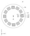
본 발명에 따른 마이크로 구조체 제조 장치는 제1회전축을 중심으로 회전가능한 회전 유닛; 및 상기 제1회전축으로부터 기 설정된 거리에서 상기 회전 유닛과 결합하고, 제2회전축을 중심으로 상기 회전 유닛에 대해 상대 회전이 가능하며, 마이크로 구조체 제조용 몰드를 지지하는 몰드 지지 유닛을 포함하되, 상기 몰드 지지 유닛은, 상기 몰드가 놓이는 지지 영역이 형성된 지지 플레이트를 포함하고, 상기 제1회전축을 중심으로 회전하는 상기 회전 유닛의 원심력에 의해 상기 몰드 지지 유닛이 상기 제2회전축을 중심으로 회전하여 상기 지지 영역이 상기 제1회전축을 향할 수 있다.A microstructure manufacturing apparatus according to the present invention includes a rotation unit rotatable about a first rotation axis; and a mold support unit coupled to the rotation unit at a preset distance from the first rotation axis, capable of relative rotation with respect to the rotation unit about a second rotation axis, and supporting a mold for manufacturing a microstructure, wherein the mold The support unit includes a support plate on which a support area on which the mold is placed is formed, and the mold support unit rotates about the second rotation axis by the centrifugal force of the rotation unit rotating about the first rotation axis to support the mold support unit. The area may face the first rotation axis.
또한, 상기 몰드 지지 유닛은 복수 개가 상기 제1회전축을 중심으로 링 형상으로 배치되고, 상기 제1회전축으로부터 동일한 거리에 위치할 수 있다.Additionally, a plurality of mold support units may be arranged in a ring shape around the first rotation axis and may be located at the same distance from the first rotation axis.
또한, 상기 지지 영역은, 상기 몰드가 놓이는 상면이 제1각도로 배치되는 제1지지 영역; 및 상기 몰드가 놓이는 상면이 상기 제1각도와 상이한 제2각도로 배치되는 제2지지 영역을 포함할 수 있다.Additionally, the support area may include: a first support area where the upper surface on which the mold is placed is disposed at a first angle; and a second support area where the upper surface on which the mold is placed is disposed at a second angle different from the first angle.
또한, 상기 제1지지 영역의 상면은 상기 지지 플레이트의 상면과 나란하고, 상기 제2지지 영역의 상면은 상기 지지 플레이트의 상면에 대해 상기 제2각도로 경사지게 배치될 수 있다.Additionally, the upper surface of the first support area may be parallel to the upper surface of the support plate, and the upper surface of the second support area may be inclined at the second angle with respect to the upper surface of the support plate.
또한, 상기 제1지지 영역의 상면은 상기 지지 플레이트의 상면과 나란하게 배치되고, 상기 제2지지 영역의 상면은 상기 지지 플레이트의 상면에 대해 경사지게 배치될 수 있다.Additionally, the upper surface of the first support area may be arranged parallel to the upper surface of the support plate, and the upper surface of the second support area may be disposed to be inclined with respect to the upper surface of the support plate.
또한, 상기 몰드 지지 유닛은, 내측으로 상기 지지 영역이 삽입될 수 있는 개구가 형성되고, 상기 개구를 형성하는 내측면에 상기 몰드가 놓이는 지지턱이 형성된 로딩 플레이트를 더 포함할 수 있다.In addition, the mold support unit may further include a loading plate having an opening inside which the support area can be inserted, and a support jaw on which the mold is placed on the inner surface forming the opening.
본 발명에 의하면, 회전 유닛이 제1회전축을 중심으로 회전하는 경우, 지지 플레이트의 지지영역에 놓인 몰드가 제1회전축을 향해 배치되고, 회전 유닛의 원심력에 의해 조성물이 몰드의 각 영역으로 일정한 두께로 펼쳐지고, 몰드의 니들 홈에 정확하게 채워질 수 있다.According to the present invention, when the rotation unit rotates about the first rotation axis, the mold placed in the support area of the support plate is disposed toward the first rotation axis, and the centrifugal force of the rotation unit spreads the composition to each area of the mold at a constant thickness. It can be expanded and accurately filled into the needle groove of the mold.
도 1은 본 발명의 일 실시 예에 따른 마이크로 구조체 제조 장치를 나타내는 도면이다.
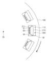
도 2는 도 1의 마이크로 구조체 제조 장치의 고속 회전 상태를 나타내는 도면이다.
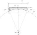
도 3은 본 발명의 다른 실시 예에 따른 마이크로 구조체 제조 장치를 나타내는 도면이다.
도 4는 도 3의 몰드 지지 유닛을 나타내는 도면이다.
도 5는 도 4의 마이크로 구조체 제조 장치의 회전 상태를 나타내는 도면이다.
도 6은 본 발명의 다른 실시 예에 따른 지지 플레이트를 나타내는 도면이다.
도 7은 도 4의 실시 예에 따른 몰드 지지 유닛을 이용하여 제조한 마이크로 구조체를 나타내는 도면이다.
도 8은 비교 예에 따른 몰드 지지 유닛을 이용하여 제조한 마이크로 구조체를 나타내는 도면이다.
도 9는 본 발명의 다른 실시예에 따른 몰드 지지 유닛을 나타내는 평면도이다.
도 10은 도 9의 몰드 지지 유닛을 나타내는 단면도이다.
도 11은 본 발명의 또 다른 실시 예에 따른 몰드 지지 유닛을 나타내는 도면이다.
도 12는 도 11의 몰드 지지 유닛을 나타내는 분해도이다.
도 13은 본 발명의 또 다른 실시 예에 따른 몰드 지지 유닛을 나타내는 도면이다.
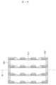
도 14는 도 13의 몰드 지지 유닛이 복수 개 적층된 모습을 나타내는 도면이다.
도 15는 도 13의 몰드 지지 유닛이 제2회전축을 중심으로 90도 회전한 모습을 나타내는 도면이다.
도 16은 본 발명의 또 다른 실시 예에 따른 몰드 지지 유닛을 나타내는 도면이다.
도 17은 본 발명의 또 다른 실시 예에 따른 마이크로 구조체 제조 장치를 나타내는 도면이다.
도 18은 본 발명의 또 다른 실시 예에 따른 마이크로 구조체 제조 장치를 나타내는 도면이다.1 is a diagram showing a microstructure manufacturing apparatus according to an embodiment of the present invention.
FIG. 2 is a diagram showing a high-speed rotation state of the microstructure manufacturing device of FIG. 1.
Figure 3 is a diagram showing a microstructure manufacturing apparatus according to another embodiment of the present invention.
FIG. 4 is a diagram showing the mold support unit of FIG. 3.
Figure 5 is a diagram showing the rotation state of the microstructure manufacturing apparatus of Figure 4.
Figure 6 is a diagram showing a support plate according to another embodiment of the present invention.
FIG. 7 is a diagram showing a microstructure manufactured using the mold support unit according to the embodiment of FIG. 4.
Figure 8 is a diagram showing a microstructure manufactured using a mold support unit according to a comparative example.
Figure 9 is a plan view showing a mold support unit according to another embodiment of the present invention.
FIG. 10 is a cross-sectional view showing the mold support unit of FIG. 9.
Figure 11 is a diagram showing a mold support unit according to another embodiment of the present invention.
Figure 12 is an exploded view showing the mold support unit of Figure 11.
Figure 13 is a diagram showing a mold support unit according to another embodiment of the present invention.
FIG. 14 is a diagram showing a plurality of mold support units of FIG. 13 stacked.
FIG. 15 is a view showing the mold support unit of FIG. 13 rotated 90 degrees about the second rotation axis.
Figure 16 is a diagram showing a mold support unit according to another embodiment of the present invention.
Figure 17 is a diagram showing a microstructure manufacturing apparatus according to another embodiment of the present invention.
Figure 18 is a diagram showing a microstructure manufacturing apparatus according to another embodiment of the present invention.
이하, 첨부된 도면들을 참조하여 본 발명의 바람직한 실시 예를 상세히 설명할 것이다. 그러나 본 발명의 기술적 사상은 여기서 설명되는 실시 예에 한정되지 않고 다른 형태로 구체화될 수도 있다. 오히려, 여기서 소개되는 실시 예는 개시된 내용이 철저하고 완전해질 수 있도록 그리고 당업자에게 본 발명의 사상이 충분히 전달될 수 있도록 하기 위해 제공되는 것이다.Hereinafter, preferred embodiments of the present invention will be described in detail with reference to the attached drawings. However, the technical idea of the present invention is not limited to the embodiments described herein and may be embodied in other forms. Rather, the embodiments introduced herein are provided so that the disclosed content will be thorough and complete and so that the spirit of the present invention can be sufficiently conveyed to those skilled in the art.
본 명세서에서, 어떤 구성요소가 다른 구성요소 상에 있다고 언급되는 경우에 그것은 다른 구성요소 상에 직접 형성될 수 있거나 또는 그들 사이에 제 3의 구성요소가 개재될 수도 있다는 것을 의미한다. 또한, 도면들에 있어서, 막 및 영역들의 두께는 기술적 내용의 효과적인 설명을 위해 과장된 것이다.In this specification, when an element is referred to as being on another element, it means that it may be formed directly on the other element or that a third element may be interposed between them. Additionally, in the drawings, the thicknesses of films and regions are exaggerated for effective explanation of technical content.
또한, 본 명세서의 다양한 실시 예 들에서 제1, 제2, 제3 등의 용어가 다양한 구성요소들을 기술하기 위해서 사용되었지만, 이들 구성요소들이 이 같은 용어들에 의해서 한정되어서는 안 된다. 이들 용어들은 단지 어느 구성요소를 다른 구성요소와 구별시키기 위해서 사용되었을 뿐이다. 따라서, 어느 한 실시 예에 제 1 구성요소로 언급된 것이 다른 실시 예에서는 제 2 구성요소로 언급될 수도 있다. 여기에 설명되고 예시되는 각 실시 예는 그것의 상보적인 실시 예도 포함한다. 또한, 본 명세서에서 '및/또는'은 전후에 나열한 구성요소들 중 적어도 하나를 포함하는 의미로 사용되었다.Additionally, in various embodiments of the present specification, terms such as first, second, and third are used to describe various components, but these components should not be limited by these terms. These terms are merely used to distinguish one component from another. Accordingly, what is referred to as a first component in one embodiment may be referred to as a second component in another embodiment. Each embodiment described and illustrated herein also includes its complementary embodiment. Additionally, in this specification, 'and/or' is used to mean including at least one of the components listed before and after.
명세서에서 단수의 표현은 문맥상 명백하게 다르게 뜻하지 않는 한 복수의 표현을 포함한다. 또한, "포함하다" 또는 "가지다" 등의 용어는 명세서상에 기재된 특징, 숫자, 단계, 구성요소 또는 이들을 조합한 것이 존재함을 지정하려는 것이지, 하나 또는 그 이상의 다른 특징이나 숫자, 단계, 구성요소 또는 이들을 조합한 것들의 존재 또는 부가 가능성을 배제하는 것으로 이해되어서는 안 된다. 또한, 본 명세서에서 "연결"은 복수의 구성 요소를 간접적으로 연결하는 것, 및 직접적으로 연결하는 것을 모두 포함하는 의미로 사용된다.In the specification, singular expressions include plural expressions unless the context clearly dictates otherwise. In addition, terms such as "include" or "have" are intended to designate the presence of features, numbers, steps, components, or a combination thereof described in the specification, but are not intended to indicate the presence of one or more other features, numbers, steps, or components. It should not be understood as excluding the possibility of the presence or addition of elements or combinations thereof. In addition, in this specification, “connection” is used to include both indirectly connecting a plurality of components and directly connecting them.
또한, 하기에서 본 발명을 설명함에 있어 관련된 공지 기능 또는 구성에 대한 구체적인 설명이 본 발명의 요지를 불필요하게 흐릴 수 있다고 판단되는 경우에는 그 상세한 설명은 생략할 것이다.In addition, in the following description of the present invention, if a detailed description of a related known function or configuration is judged to unnecessarily obscure the gist of the present invention, the detailed description will be omitted.
아래에서 설명되는 다양한 실시예들에 따른 마이크로 구조체 제조 장치는 신체에 약물을 전달할 수 있는 마이크로 구조체를 제조할 수 있다. 마이크로 구조체는 두께가 얇은 베이스 레이어(Base layer)와 베이스 레이어의 일면에 형성된 복수의 니들(needle)이 결합된 구조로, 니들이 피부 조직에 삽입되어 약물을 전달할 수 있다. 이러한 마이크로 구조체는 마이크로 구조체 제조용 몰드(이하 '몰드' 라고 한다)의 니들 홈에 조성물을 채워 제조한다. 조성물은 생체적합성 또는 생분해성 물질일 수 있다. 생체적합성 또는 생분해성 물질은 실질적으로 인체에 독성이 없고 화학적으로 불활성이며 면역원성이 없는 물질로, 최종적으로 체내 침투 후 용해되는 이점을 가진다.The microstructure manufacturing apparatus according to various embodiments described below can manufacture microstructures capable of delivering drugs to the body. The microstructure is a structure that combines a thin base layer and a plurality of needles formed on one side of the base layer, and the needles can be inserted into skin tissue to deliver drugs. These microstructures are manufactured by filling the needle grooves of a mold for manufacturing microstructures (hereinafter referred to as 'mold') with a composition. The composition may be biocompatible or biodegradable. Biocompatible or biodegradable materials are substances that are substantially non-toxic to the human body, chemically inert, and non-immunogenic, and have the advantage of being dissolved after finally penetrating into the body.
이러한 생체적합성 물질의 종류는 특별히 제한되지 않으며, 예를 들어, 히알루론산, 폴리에스테르, 폴리하이드록시알카노에이트(PHAs), 폴리(α-하이드록시액시드), 폴리(β-하이드록시액시드), 폴리(3-하이드로식부티레이트-co-발러레이트; PHBV), 폴리(3-하이드록시프로프리오네이트; PHP), 폴리(3-하이드록시헥사노에이트; PHH), 폴리(4-하이드록시액시드), 폴리(4-하이드록시부티레이트), 폴리(4-하이드록시발러레이트), 폴리(4-하이드록시헥사노에이트), 폴리(에스테르아마이드), 폴리카프로락톤, 폴리락타이드, 폴리글리코라이드, 폴리(락타이드-co-글리코라이드; PLGA), 폴리디옥사논, 폴리오르토에스테르, 폴리에테르에스테르, 폴리언하이드라이드, 폴리(글리콜산-co-트리메틸렌 카보네이트), 폴리포스포에스테르, 폴리포스포에스테르 우레탄, 폴리(아미노산), 폴리사이아노아크릴레이트, 폴리(트리메틸렌 카보네이트), 폴리(이미노카보네이트), 폴리(타이로신 카보네이트), 폴리카보네이트, 폴리(타이로신 아릴레이트), 폴리알킬렌 옥살레이트, 폴리포스파젠스, PHA-PEG, 에틸렌 비닐 알코올 코폴리머(EVOH), 폴리우레탄, 실리콘, 폴리에스테르, 폴리올레핀, 폴리이소부틸렌과 에틸렌-알파올레핀 공중합체, 스틸렌-이소브틸렌-스틸렌 트리블록 공중합체, 아크릴 중합체 및 공중합체, 비닐 할라이드 중합체 및 공중합체, 폴리비닐 클 로라이드, 폴리비닐 에테르, 폴리비닐 메틸 에테르, 폴리비닐리덴 할라이드, 폴리비닐리덴 플루오라이드, 폴리비닐리덴 클로라이드, 폴리플루오로알켄, 폴리퍼플루오로알켄, 폴리아크릴로니트릴, 폴리비닐 케톤, 폴리비닐아로마틱스, 폴리스틸렌, 폴리비닐 에스테르, 폴리비닐 아세테이트, 에틸렌-메틸 메타크릴레이트 공중합체, 아크릴로니트릴-스틸렌 공중합체, ABS 수지와 에틸렌-비닐 아세테이트 공중합체, 폴리아마이드, 알키드 수지, 폴리옥시메틸렌, 폴리이미드, 폴리에테르, 폴리아크릴레이트, 폴리메타크릴레이트, 폴리아크릴산-co-말레산, 키토산, 덱스트란, 셀룰로오스, 헤파린, 알기네이트, 이눌린, 녹말 또는 글리코겐을 사용할 수 있고, 히알루론산, 폴리에스테르, 폴리하이드록시알카노에이트(PHAs), 폴리(α-하이드록시액시드), 폴리(β-하이드록시액시드), 폴리(3-하이드로식부티레이트-co-발러레이트; PHBV), 폴리(3-하이드록시프로프리오네이트; PHP), 폴리(3-하이드록시헥사노에이트; PHH), 폴리(4-하이드록시액시드), 폴리(4-하이드록시부티레이트), 폴리(4-하이드록시발러레이트), 폴리(4-하이드록시헥사노에이트), 폴리(에스테르아마이드), 폴리카프로락톤, 폴리락타이드, 폴리글리코라이드, 폴리(락타이드-co-글리코라이드; PLGA), 폴리디옥사논, 폴리오르토에스테르, 폴리에테르에스테르, 폴리언하이드라이드, 폴리(글리콜산-co-트리메틸렌 카보네이트), 폴리포스포에스테르, 폴리포스포에스테르우레탄, 폴리(아미노산), 폴리사이아노아크릴레이트, 폴리(트리메틸렌 카보네이트), 폴리(이미노카보네이트), 폴리(타이로신 카보네이트), 폴리카보네이트, 폴리(타이로신 아릴레이트), 폴리알킬렌 옥살레이트, 폴리포스파젠스, PHAPEG, 키토산, 덱스트란, 셀룰로오스, 헤파린, 알기네이트, 이눌린, 녹말 및 글리코겐으로 이루어진 그룹으로부터 선택된 하나 이상을 사용할 수 있다.The types of these biocompatible materials are not particularly limited and include, for example, hyaluronic acid, polyester, polyhydroxyalkanoates (PHAs), poly(α-hydroxyacid), and poly(β-hydroxyacid). ), poly(3-hydroxybutyrate-co-valerate; PHBV), poly(3-hydroxypropionate; PHP), poly(3-hydroxyhexanoate; PHH), poly(4-hyde) Roxyacid), poly(4-hydroxybutyrate), poly(4-hydroxyvalerate), poly(4-hydroxyhexanoate), poly(esteramide), polycaprolactone, polylactide, poly Glycolide, poly(lactide-co-glycolide; PLGA), polydioxanone, polyorthoester, polyether ester, polyanhydride, poly(glycolic acid-co-trimethylene carbonate), polyphosphoester , polyphosphoester urethane, poly(amino acid), polycyanoacrylate, poly(trimethylene carbonate), poly(iminocarbonate), poly(tyrosine carbonate), polycarbonate, poly(tyrosine arylate), polyalkyl Len oxalate, polyphosphazenes, PHA-PEG, ethylene vinyl alcohol copolymer (EVOH), polyurethanes, silicones, polyesters, polyolefins, polyisobutylene and ethylene-alphaolefin copolymers, styrene-isobutylene- Styrene triblock copolymers, acrylic polymers and copolymers, vinyl halide polymers and copolymers, polyvinyl chloride, polyvinyl ether, polyvinyl methyl ether, polyvinylidene halide, polyvinylidene fluoride, polyvinylidene chloride, Polyfluoroalkene, polyperfluoroalkene, polyacrylonitrile, polyvinyl ketone, polyvinyl aromatics, polystyrene, polyvinyl ester, polyvinyl acetate, ethylene-methyl methacrylate copolymer, acrylonitrile-styrene copolymer. Polymer, ABS resin and ethylene-vinyl acetate copolymer, polyamide, alkyd resin, polyoxymethylene, polyimide, polyether, polyacrylate, polymethacrylate, polyacrylic acid-co-maleic acid, chitosan, dextran, Cellulose, heparin, alginate, inulin, starch, or glycogen can be used, as well as hyaluronic acid, polyester, polyhydroxyalkanoates (PHAs), poly(α-hydroxy acid), and poly(β-hydroxy acid). Seed), poly(3-hydrosybutyrate-co-valerate; PHBV), poly (3-hydroxypropionate; PHP), poly (3-hydroxyhexanoate; PHH), poly (4-hydroxy acid), poly (4-hydroxybutyrate), poly (4-hydroxyvalerate), poly(4-hydroxyhexanoate), poly(esteramide), polycaprolactone, polylactide, polyglycolide, poly(lactide-co-glycolide; PLGA) , polydioxanone, polyorthoester, polyether ester, polyanhydride, poly(glycolic acid-co-trimethylene carbonate), polyphosphoester, polyphosphoester urethane, poly(amino acid), polycyano Acrylate, poly(trimethylene carbonate), poly(iminocarbonate), poly(tyrosine carbonate), polycarbonate, poly(tyrosine arylate), polyalkylene oxalate, polyphosphazene, PHAPEG, chitosan, dextran , cellulose, heparin, alginate, inulin, starch, and glycogen can be used.
상기 마이크로 구조체가 생체 적합성 또는 생분해성 물질이 탑재된 솔리드형 마이크로 니들인 경우, 약물을 추가적으로 탑재할 수 있다. 상기 약물은 광의의 개념을 의미하며, 협의의 치료 목적의 치료제뿐만 아니라, 에너지, 나노 성분, 미용 성분(예컨대, 주름개선제, 피부노화 억제제 및 피부 미백제), 세포 배양액 등을 모두 포함한다.If the microstructure is a solid microneedle loaded with a biocompatible or biodegradable material, a drug can be additionally loaded. The drug refers to a broad concept and includes not only therapeutic agents in the narrow sense, but also energy, nano-ingredients, cosmetic ingredients (e.g., anti-wrinkle agents, skin aging inhibitors, and skin whitening agents), cell culture media, etc.
구체적으로, 상기 치료제로는 화학약물, 단백질/펩타이드의 약, 펩타이드의 약,유전자 치료용 핵산 분자 등을 포함한다.Specifically, the therapeutic agent includes chemical drugs, protein/peptide drugs, peptide drugs, nucleic acid molecules for gene therapy, etc.
예를 들어, 치료제는 항염증제, 진통제, 항관절염제, 진경제, 항우울증제, 항정신병약물, 신경안정제, 항불안제, 마약길항제, 항파킨스질환 약물, 콜린성 아고니스트, 항암제, 항혈관신생억제제, 면역억제제, 항바이러스제, 항생제, 식욕억제제, 진통제, 항콜린제, 항히스타민제, 항편두통제, 호르몬제, 관상혈관, 뇌혈관 또는 말초혈관 확장제, 피임약, 항혈전제, 이뇨제, 항고혈압제, 심혈관질환 치료제 등을 포함할 수 있다.For example, therapeutic agents include anti-inflammatory drugs, analgesics, anti-arthritis drugs, antispasmodics, antidepressants, antipsychotics, tranquilizers, anti-anxiety drugs, narcotic antagonists, anti-Parkinson disease drugs, cholinergic agonists, anticancer drugs, anti-angiogenesis inhibitors, and immunosuppressants. , antiviral drugs, antibiotics, appetite suppressants, painkillers, anticholinergics, antihistamines, anti-migraine drugs, hormones, coronary, cerebrovascular or peripheral vasodilators, contraceptives, antithrombotic agents, diuretics, antihypertensive drugs, cardiovascular disease treatments, etc. It can be included.
특히, 단백질/펩타이드 의약은 호르몬, 호르몬 유사체, 효소, 효소저해제, 신호전달단백질 또는 그 일부분, 항체 또는 그 일부분, 단쇄항체, 결합단백질 또는 그 결합도메인, 항원, 부착단백질, 구조단백질, 조절단백질, 독소단백질, 사이토카인, 전사조절 인자, 혈액 응고 인자 및 백신 등을 포함할 수 있다. 보다 상세하게는, 상기 단백질/펩타이드 의약은 인슐린, IGF-1(insulin-like growth factor 1), 성장호르몬, 에리쓰로포이에틴, G-CSFs (granulocyte-colony stimulating factors), GM-CSFs(granulocyte/macrophagecolony stimulating factors), 인터페론 알파, 인터페론 베타, 인터페론 감마, 인터루킨-1 알파 및 베타, 인터루킨-3, 인터루킨-4, 인터루킨-6, 인터루킨-2, EGFs (epidermal growth factors), 칼시토닌(calcitonin), ACTH(adrenocorticotropic hormone), TNF (tumor necrosis factor), 아토비스반(atobisban), 부세레린(buserelin), 세트로렉릭스(cetrorelix), 데스로레린(deslorelin), 데스모프레신(desmopressin), 디노르핀 A(dynorphin A) (1-13), 엘카토닌(elcatonin), 엘레이도신(eleidosin), 엡티피바타이드(eptifibatide), GHRHII(growth hormone releasing hormone-II), 고나도레린(gonadorelin), 고세레린(goserelin), 히스트레린(histrelin), 류프로레린(leuprorelin), 라이프레신(lypressin), 옥트레오타이드(octreotide), 옥시토신(oxytocin), 피트레신(pitressin), 세크레틴(secretin), 신칼라이드(sincalide), 테르리프레신(terlipressin), 티모펜틴(thymopentin), 티모신(thymosine) α1, 트리프토레린(triptorelin), 바이발리루딘(bivalirudin), 카르베토신(carbetocin), 사이클로스포린, 엑세딘(exedine), 란레오타이드(lanreotide), LHRH (luteinizing hormone-releasing hormone), 나파레린(nafarelin), 부갑상선 호르몬, 프람린타이드(pramlintide), T-20(enfuvirtide), 타이말파신(thymalfasin) 및 지코노타이드를 포함할 수 있다.In particular, protein/peptide medicines include hormones, hormone analogs, enzymes, enzyme inhibitors, signal transduction proteins or parts thereof, antibodies or parts thereof, single-chain antibodies, binding proteins or their binding domains, antigens, attachment proteins, structural proteins, regulatory proteins, It may include toxin proteins, cytokines, transcriptional regulatory factors, blood coagulation factors, and vaccines. More specifically, the protein/peptide medicine contains insulin, IGF-1 (insulin-like growth factor 1), growth hormone, erythropoietin, G-CSFs (granulocyte-colony stimulating factors), and GM-CSFs (granulocyte /macrophagecolony stimulating factors), interferon alpha, interferon beta, interferon gamma, interleukin-1 alpha and beta, interleukin-3, interleukin-4, interleukin-6, interleukin-2, EGFs (epidermal growth factors), calcitonin, ACTH (adrenocorticotropic hormone), TNF (tumor necrosis factor), atobisban, buserelin, cetrorelix, deslorelin, desmopressin, Dynorphin A (1-13), elcatonin, eleidosin, eptifibatide, growth hormone releasing hormone-II (GHRHII), gonadorelin , goserelin, histrelin, leuprorelin, lypressin, octreotide, oxytocin, pitressin, secretin , sincalide, terlipressin, thymopentin, thymosine α1, triptorelin, bivalirudin, carbetocin, Cyclosporine, exedine, lanreotide, LHRH (luteinizing hormone-releasing hormone), nafarelin, parathyroid hormone, pramlintide, T-20 (enfuvirtide), Tymal May include thymalfasin and ziconotide.
몰드는 다양한 형상을 가질 수 있다. 본 발명의 도면에서는 몰드가 사각 형상으로 도시되었으나, 이에 국한되지 않으며, 원형 또는 다각형상을 가질 수 있다. 이러한 몰드의 형상에 따라 사각형, 원형, 그리고 다각형의 베이스 레이어가 제조될 수 있다.The mold can have various shapes. In the drawings of the present invention, the mold is shown as a square shape, but it is not limited to this and may have a circular or polygonal shape. Depending on the shape of the mold, square, circular, and polygonal base layers can be manufactured.
이하 본 발명에 따른 마이크로 구조체 제조 장치에 대해 상세하게 설명한다.Hereinafter, the microstructure manufacturing apparatus according to the present invention will be described in detail.
도 1은 본 발명의 일 실시 예에 따른 마이크로 구조체 제조 장치를 나타내는 도면이고, 도 2는 도 1의 마이크로 구조체 제조 장치의 고속 회전 상태를 나타내는 도면이다.FIG. 1 is a diagram illustrating a microstructure manufacturing apparatus according to an embodiment of the present invention, and FIG. 2 is a diagram illustrating a high-speed rotation state of the microstructure manufacturing apparatus of FIG. 1 .
도 1 및 도 2를 참조하면, 마이크로 구조체 제조 장치(10)는 회전 유닛(100)과 몰드 지지 유닛(200)을 포함한다.Referring to FIGS. 1 and 2 , the
회전 유닛(100)은 제1회전축(20)을 중심으로 회전가능한 구성으로, 다양한 형상으로 제공될 수 있다. 일 실시 예에 의하면, 회전 유닛(100)은 제1회전축(20)을 중심으로 회전가능한 원형 판으로 제공될 수 있다. 다른 실시 예에 의하면, 회전 유닛(100)은 제1회전축(20)을 중심으로 회전가능한 원형 프레임으로 제공될 수 있다. 제1회전축(20)은 지면에 수직하게 제공될 수 있다.The
회전 유닛(100)에는 몰드 지지 유닛(200)이 위치할 수 있는 수용 공간(110)이 형성된다. 실시 예에 의하면, 수용 공간(110)은 복수 개 형성되며, 제1회전축(20)을 중심으로 원형으로 배치된다. 각각의 수용 공간(110)은 제1회전축(20)으로부터 동일 거리에 위치할 수 있다.An
몰드 지지 유닛(200)은 몰드(50)를 지지한다. 몰드 지지 유닛(200)은 수용 공간(110)에 각각 위치하며, 제2회전축(30)을 중심으로 회전 가능하도록 회전 유닛(100)과 결합한다. 제2회전축(30)은 몰드 지지 유닛(200)들의 배열 방향인 상기 원형에 대해 접선 방향으로 배치된다. 제2회전축(30)는 몰드 지지 유닛(200)의 회전 반경 방향에 수직하게 배치될 수 있다.The
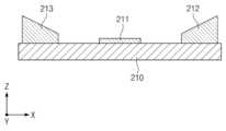
몰드 지지 유닛(200)은 지지 플레이트(210)를 포함한다. 지지 플레이트(210)는 소정 면적을 갖고, 두께가 얇은 판으로 일 면에는 지지 영역(211)이 형성된다. 지지 영역(211)의 상면에는 몰드(50)가 놓인다. 지지 영역(211)의 상면은 평평한 면으로 제공된다.The
몰드(50)가 지지 영역(211)에 놓인 상태에서 몰드(50)의 상면에 조성물(60)이 공급된다. 조성물(60)은 높은 점성으로 인해 몰드(50)의 니들 홈(51)에 바로 투입되지 못한다. 이 상태에서 회전 유닛(100)이 제1회전축(20)을 중심으로 고속 회전하면, 원심력에 의해 몰드 지지 유닛(200)이 제2회전축(30)을 중심으로 90도 회전하여 지지 플레이트(210)가 회전 유닛(100)의 회전 반경 방향에 수직하게 배치되고, 지지 영역(211)이 제1회전축(20)을 향해 배치된다. 회전 유닛(100)의 원심력은 몰드(50)의 상면에 수직하게 작용 후 방사상으로 펼쳐지므로, 조성물(60)이 몰드(50)의 각 영역으로 균일하게 펼쳐져 니들 홈(51)으로 투입될 수 있다. 조성물(60)은 회전 유닛(100)의 원심력 방향으로 니들 홈(51)의 깊숙이 침투할 수 있다.The
도 3은 본 발명의 다른 실시 예에 따른 마이크로 구조체 제조 장치를 나타내는 도면이고, 도 4는 도 3의 몰드 지지 유닛을 나타내는 도면이고, 도 5는 도 4의 마이크로 구조체 제조 장치의 회전 상태를 나타내는 도면이다.FIG. 3 is a diagram showing a microstructure manufacturing apparatus according to another embodiment of the present invention, FIG. 4 is a diagram showing the mold support unit of FIG. 3, and FIG. 5 is a diagram showing the rotation state of the microstructure manufacturing apparatus of FIG. 4. am.
먼저, 도 3 및 도 4를 참조하면, 회전 유닛(100)에는 복수 개의 수용 공간(110)이 형성된다. 실시 예에 의하면, 수용 공간(110)은 4개 형성되며, 90도 사이각으로 배치된다. 수용 공간(110)은 소정 길이로 형성되며, 그 길이방향이 회전 유닛(100)의 반경 방향에 수직하게 배치된다.First, referring to FIGS. 3 and 4, a plurality of
몰드 지지 유닛(200)은 수용 공간(110)에 각각 위치하며, 제2회전축(30)을 중심으로 회전 가능하도록 회전 유닛(100)과 결합한다. 몰드 지지 유닛(200)은 지지 플레이트(210)를 포함한다. 지지 플레이트(210)는 수용 공간(110)에 상응하는 면적을 가지며, 일 면에는 복수 개의 지지 영역(211, 212, 213)이 형성된다. 지지 영역(211, 212, 213)에는 몰드(50)가 각각 놓인다. 실시 예에 의하면, 지지 플레이트(210)의 상면에는 3개의 지지 영역(211, 212, 213)이 제공되며, 제1지지 영역(211)은 지지 플레이트(210)의 중앙에 위치하고, 제1지지 영역(211)의 양 측에 제2지지 영역(212)과 제3지지 영역(213)이 각각 위치한다.The
제1지지 영역(211)의 상면은 제1각도(θ1)로 배치된다. 실시 예에 의하면, 제1각도(211)는 지지 플레이트(210)의 상면과 0°를 이루는 각도로, 제1지지 영역(211)의 상면은 지지 플레이트(210)의 상면과 나란하게 배치된다.The upper surface of the
제2지지 영역(212)의 상면은 제2각도(θ2)로 배치된다. 제2각도(θ2)는 제1각도(θ1)와 상이한 각도로, 지지 플레이트(210)의 중심을 기준으로 지지 플레이트(210)의 상면과 0°보다 크고 90°보다 작은 각도를 이룰 수 있다. 실시 예에 의하면, 제2각도(θ2)는 지지 플레이트(210)의 상면과 1°보다 크고 60°보다 작은 각도를 이룰 수 있다. 이로 인해 제2지지 영역(212)의 상면은 지지 플레이트(210)의 상면과 제2각도(θ2)로 경사지게 배치될 수 있다. 구체적으로, 제2지지 영역(212)은 제1지지 영역(211)에 인접한 선단이 후단보다 높이가 낮게 제공되어 상면이 제1지지 영역(211) 측으로 제2각도(θ1)로 하향 경사지게 제공된다.The upper surface of the
제3지지 영역(213)의 상면은 제3각도(θ3)로 배치된다. 제3각도(θ3)는 제1각도(θ1) 및 제2각도(θ2)와 상이한 각도로, 지지 플레이트(210)의 중심을 기준으로 지지 플레이트(210)의 상면과 90°보다 크고 180°보다 작은 각도를 이룰 수 있다. 실시 예에 의하면, 제3각도(θ3)는 지지 플레이트(210))의 상면과 91°보다 크고 150°보다 작은 각도를 이룰 수 있다. 이로 인해 제3지지 영역(213)의 상면은 지지 플레이트(210)의 상면과 제3각도(θ3)로 경사지게 배치될 수 있다. 구체적으로, 제3지지 영역(213)은 제1지지 영역(211)에 인접한 선단이 후단보다 높이가 낮게 제공되며, 상면이 제1지지 영역(211) 측으로 제3각도(θ3)로 하향 경사지게 제공된다. 제3지지 영역(213)의 상면은 제1지지 영역(211)을 중심으로, 제2지지 영역(212)의 상면과 대칭될 수 있다.The upper surface of the
도 5를 참조하면, 회전 유닛(100)이 제1회전축(20)을 중심으로 고속 회전하면, 원심력에 의해 몰드 지지 유닛(200)이 제2회전축(30)을 중심으로 90도 회전하여 지지 플레이트(210)의 일 면이 회전 유닛(100)의 회전 반경 방향에 수직하게 배치된다. 이 때, 제1회전축(20)에서 지지 영역(211, 212, 213)들 각각의 상면을 연결하는 최단 거리(r)를 반경으로 하는 가상의 원(70)을 기준으로, 지지 영역(211, 212, 213)들의 상면은 가상의 원(70)의 접선 방향으로 배치된다. 때문에, 회전 유닛(100)의 원심력이 몰드(50)의 상면에 수직하게 제공되어 조성물(60)이 몰드(50)의 각 영역으로 균일하게 펼쳐질 수 있다.Referring to FIG. 5, when the
본 실시 예에서는, 지지 플레이트(210)에 3개의 지지 영역(211, 212, 213)이 제공되는 것으로 설명하였으나, 지지 영역의 개수는 다양하게 변경될 수 있다. 일 예로, 도 6을 참조하면, 지지 플레이트(210)에는 9개의 지지 영역(211 내지 219)이 제공될 수 있다. 지지 플레이트(210)의 중앙에 위치한 제1지지 영역(211)을 기준으로 양측에 각각 4개씩 지지 영역(212 내지 219)이 제공될 수 있다. 지지 영역(211 내지 219)들의 상면은 서로 다른 각도로 배치되며, 지지 플레이트(210)의 중앙에서 멀어질수록 각도가 점차 증가한다. 그리고 지지 영역(212 내지 219)들의 경사 각도는 제1지지 영역(211)을 기준으로 서로 대칭될 수 있다.In this embodiment, it has been described that three
도 7은 도 4의 실시 예에 따른 몰드 지지 유닛을 이용하여 제조한 마이크로 구조체를 나타내는 도면이고, 도 8은 비교 예에 따른 몰드 지지 유닛을 이용하여 제조한 마이크로 구조체를 나타내는 도면이다. 비교 예에 따른 몰드 지지 유닛(300)은 제1 내지 제3지지 영역(311 내지 313)의 상면이 모두 평평한 면으로 제공된다.FIG. 7 is a diagram showing a microstructure manufactured using a mold support unit according to the embodiment of FIG. 4, and FIG. 8 is a diagram showing a microstructure manufactured using a mold support unit according to a comparative example. In the mold support unit 300 according to the comparative example, all upper surfaces of the first to third support regions 311 to 313 are provided as flat surfaces.
먼저, 도 7을 참조하면, 회전 유닛(100)의 원심력이 제1 내지 제3지지 영역(211 내지 213)의 상면에 수직한 방향으로 제공되므로, 조성물(61 내지 63)이 몰드(50)의 각 영역으로 균일하게 펼쳐지고, 니들 홈(51)에 균일하게 투입되는 것을 확인할 수 있다.First, referring to FIG. 7, since the centrifugal force of the
반면, 도 8을 참조하면, 제1지지 영역(311)에 놓인 몰드(50)에는 조성물(71)이 균일하게 펼쳐졌으나, 제2 및 제3지지 영역(312, 313)에 놓인 몰드(50)에는 조성물(72, 73)이 외곽 영역에 집중되는 것을 확인할 수 있다. 이는 제2 및 제3지지 영역(312, 313)의 상면이 제1회전축(20)을 향해 배치되지 않아 조성물(72, 73)이 회전 유닛(100)의 원심력 방향으로 펼쳐진 결과로 이해된다.On the other hand, referring to FIG. 8, the composition 71 was spread uniformly in the
도 9는 본 발명의 다른 실시예에 따른 몰드 지지 유닛을 나타내는 평면도이고, 도 10은 도 9의 몰드 지지 유닛을 나타내는 단면도이다.Figure 9 is a plan view showing a mold support unit according to another embodiment of the present invention, and Figure 10 is a cross-sectional view showing the mold support unit of Figure 9.
도 9 및 도 10을 참조하면, 몰드 지지 유닛(200)의 지지 플레이트(100)는 상술한 제1 내지 제3지지 영역(211 내지 213)이 복수의 행으로 제공될 수 있다. Y축 방향으로 제1지지 영역(211)들이 일렬 배열되고, 제2지지 영역(212)들이 일렬 배열되고, 제3지지 영역(213)들이 일렬 배열된다. 제1지지 영역(211)들의 상면은 평평한 평면으로 제공되고, 제2지지 영역(212)들의 상면은 제2각도로 경사지게 배치되고, 제3지지 영역(213)들의 상면은 제3각도로 경사지게 배치된다.Referring to FIGS. 9 and 10 , the
상술한 몰드 지지 유닛(200)을 이용하여 마이크로 구조체를 제조할 경우, 하나의 제조 공정으로 복수개의 마이크로 구조체를 동시에 제조할 수 있다.When manufacturing a micro structure using the
도 11은 본 발명의 또 다른 실시 예에 따른 몰드 지지 유닛을 나타내는 도면이고, 도 12는 도 11의 몰드 지지 유닛을 나타내는 분해도이다.FIG. 11 is a view showing a mold support unit according to another embodiment of the present invention, and FIG. 12 is an exploded view showing the mold support unit of FIG. 11.
도 11 및 도 12를 참조하면, 몰드 지지 유닛(200)은 지지 플레이트(210)와 로딩 플레이트(220)를 포함한다.11 and 12, the
지지 플레이트(210)는 도 3 내지 도 10에서 설명한 지지 플레이트 중 어느 하나가 사용될 수 있다.As the
로딩 플레이트(220)는 지지 플레이트(210)에 상응하는 면적을 가지며, 복수 개의 개구(221 내지 223)가 형성된다. 개구(221 내지 223)는 로딩 플레이트(220)의 상면과 하면을 관통하는 홀로, 실시 예에 의하면 사각 형상으로 제공된다. 개구(211)는 지지 플레이트(210)의 지지영역(211 내지 213)들에 대응하는 위치, 개수, 그리고 크기로 형성된다. 개구(221 내지 223)를 형성하는 로딩 플레이트(220)의 내측면에는 지지턱(231 내지 233)이 형성된다. 지지턱(231 내지 233)은 개구(221 내지 223)를 형성하는 로딩 플레이트(220)의 내측면들 중 적어도 서로 마주하는 한 쌍의 내측면에 각각 형성될 수 있다. 개구(221 내지 223)에 몰드(50)가 삽입될 경우, 지지턱(231 내지 233)은 몰드(50)의 저면을 지지한다.The
이하, 상기 실시 예에 따른 몰드 지지 유닛(200)에 몰드(50)를 안착시키는 과정에 대해 설명한다.Hereinafter, the process of seating the
먼저, 지지 플레이트(210)와 로딩 플레이트(220)가 분리된 상태에서 로딩 플레이트(220)의 개구(221 내지 223)에 몰드(50)를 위치시킨다. 그리고 지지 영역(211 내지 213)과 개구(221 내지 223)가 동일 선상에 위치하도록 지지 플레이트(210)와 로딩 플레이트(220)를 위치시킨 상태에서 로딩 플레이트(220)를 아래로 이동시킨다. 이 과정에서 지지 영역(211 내지 213)들이 개구(221 내지 223)들에 삽입되며, 개구(221 내지 223)에 놓인 몰드(50)가 지지 영역(211 내지 213)들의 상면에 안착된다.First, with the
앞서 설명한 바와 같이, 지지 영역(211 내지 213)들 중 일부(212, 213)의 상면이 경사면으로 제공된다. 경사면은 경사도에 인해 몰드(50)를 일정한 위치에 안착하는 것이 쉽지 않다. 이러한 문제를 해결하기 위하여, 로딩 플레이트(220)를 이용한다. 몰드(50)를 로딩 플레이트(220)의 개구(221 내지 223)에 위치시킨 상태에서, 로딩 플레이트(220)와 지지 플레이트(210)의 결합으로, 몰드(50)를 지지 영역(211 내지 213)의 상면으로 전달한다. 이 과정에서 몰드(50)는 지지 영역(211 내지 213)의 상면에 항상 일정한 지점에 안착될 수 있다.As described above, the upper surfaces of some of the
도 13은 본 발명의 또 다른 실시 예에 따른 몰드 지지 유닛을 나타내는 도면이고, 도 14는 도 13의 몰드 지지 유닛이 복수 개 적층된 모습을 나타내는 도면이고, 도 15는 도 13의 몰드 지지 유닛이 제2회전축을 중심으로 90도 회전한 모습을 나타내는 도면이다.FIG. 13 is a view showing a mold support unit according to another embodiment of the present invention, FIG. 14 is a view showing a plurality of mold support units of FIG. 13 stacked, and FIG. 15 is a view showing the mold support unit of FIG. 13. This is a diagram showing a 90-degree rotation around the second rotation axis.
도 13 및 도 14를 참조하면, 지지 플레이트(210)의 저면에는 지지 레그(240)가 형성된다. 지지 레그(240)는 지지 플레이트(210)의 저면으로부터 아래로 소정 길이로 제공된다. 지지 레그(240)는 복수 개 제공되며, 지지 플레이트(210)의 기 설정된 지점에서 서로 이격하여 배치된다.13 and 14,
상술한 구조를 갖는 몰드 지지 유닛(200)은 복수 개가 적층될 수 있다. 구체적으로, 상부에 위치한 몰드 지지 유닛(200)에 포함된 지지 플레이트(210)는 지지 레그(240)가 하부에 위치한 몰드 지지 유닛(200)의 로딩 플레이트(220)의 상면에 놓인다. 이렇게 적측된 복수 개의 몰드 지지 유닛(200)들은 결합 수단(미도시)에 의해 일체로 결합되며, 제2회전축(30)을 중심으로 일체로 회전 가능하다.A plurality of
상기 몰드 지지 유닛(200)들에 형성된 제1지지 영역(211)들 모두는 그 상면이 지지 플레이트(210)의 상면과 나란하게 배치된다. 제2지지 영역(212)과 제3지지 영역(213)은 몰드 지지 유닛(200)에 따라 경사 각도가 상이하게 제공된다. 구체적으로, 제1회전축(20)으로부터 거리가 멀어질수록 제2지지 영역(212)과 제3지지 영역(213)의 경사 각도가 점차 작아진다. 때문에, 하부에 위치한 몰드 지지 유닛(200)의 제2지지 영역(212)과 제3지지 영역(213)의 상면은 상부에 위치한 몰드 지지 유닛(200)의 제2지지 영역(212)과 제3지지 영역(213)의 상면보다 작은 경사 각도를 갖는다.The upper surfaces of all
도 15를 참조하면, 회전 유닛(100)이 제1회전축(20)을 중심으로 고속 회전할 경우, 원심력에 의해 몰드 지지 유닛(200)들이 제2회전축(30)을 중심으로 90도 회전하여 지지 플레이트(210)들이 회전 유닛(100)의 반경 방향에 수직하게 배치된다. 그리고 상술한 제1 내지 제3지지 영역(211, 212, 213)의 상면의 경사 각도 배치로, 제1 내지 제3지지 영역(211, 212, 213)들의 상면은 제1회전축(20)을 향해 배치될 수 있다.Referring to FIG. 15, when the
도 16은 본 발명의 또 다른 실시 예에 따른 몰드 지지 유닛을 나타내는 도면이다.Figure 16 is a diagram showing a mold support unit according to another embodiment of the present invention.
도 16를 참조하면, 지지 레그(240)는 지지 플레이트(210)의 저면 가장자리영역 뿐만 아니라 중심 영역에도 형성될 수 있다. 지지 레그(240)들은 그 하부에 위치한 로딩 플레이트(220)의 상면에 놓인다. 지지 레그(240)들이 지지 플레이트(210)의 전체 영역에 걸쳐 일정 간격으로 배치됨에 따라, 고속 회전 동안 몰드를 안정적으로 지지할 수 있다.Referring to FIG. 16, the
도 17은 본 발명의 또 다른 실시 예에 따른 마이크로 구조체 제조 장치를 나타내는 도면이다.Figure 17 is a diagram showing a microstructure manufacturing apparatus according to another embodiment of the present invention.
도 17을 참조하면, 몰드 지지 유닛(200)은 몰드(50)의 상면이 제1회전축(20)을 향하도록 제2회전축(30)에 고정 위치한다. 때문에, 몰드(50)에 조성물(60)을 공급하거나, 회전 유닛(100)이 고속 회전하는 동안, 몰드(50)는 그 상면이 항상 제1회전축(20)을 향해 배치된다. 조성물(60)을 몰드(50)에 공급하는 과정에서, 조성물(60)이 자중에 의해 아래로 흘러내릴 수 있다. 때문에, 본 실시 예에 따른 마이크로 구조체 제조 장치(10)는 높은 점성을 갖는 조성물(60)에 적합하다 할 수 있다. 회전 유닛(100)의 고속 회전으로, 충분한 크기의 원심력이 몰드(50)의 상면에 전달될 수 있으므로, 높은 점성의 조성물(60)도 몰드(50)의 상면에 균일한 두께로 펼쳐질 수 있다.Referring to FIG. 17, the
도 18은 본 발명의 또 다른 실시 예에 따른 마이크로 구조체 제조 장치를 나타내는 도면이다.Figure 18 is a diagram showing a microstructure manufacturing apparatus according to another embodiment of the present invention.
도 18을 참조하면, 회전 유닛(100)은 제1회전축(20)이 지면(XY평면)과 나란하게 배치된다. 때문에, 몰드 지지 유닛(200)들은 제1회전축(20)을 중심으로 서로 상이한 높이에 위치한다. 이러한 회전 유닛(100)의 구조로 인해, 조성물(60)은 제1회전축(20)의 하부에 위치하는 몰드 지지 유닛(200)들에 안착된 몰드(50)에 공급 가능하다. 조성물이 공급되지 않는 다른 몰드 지지 유닛(200)들에는 무게 형성 지그(90)가 제공될 수 있다. 무게 형성 지그(90)는 몰드(50)와 조성물(60)을 합한 무게를 갖는 구성으로, 제1회전축(20)을 중심으로 회전 유닛(100)의 무게 중심을 맞추기 위해 제공된다.Referring to FIG. 18, the
이상, 본 발명을 바람직한 실시 예를 사용하여 상세히 설명하였으나, 본 발명의 범위는 특정 실시 예에 한정되는 것은 아니며, 첨부된 특허청구범위에 의하여 해석되어야 할 것이다. 또한, 이 기술분야에서 통상의 지식을 습득한 자라면, 본 발명의 범위에서 벗어나지 않으면서도 많은 수정과 변형이 가능함을 이해하여야 할 것이다.Above, the present invention has been described in detail using preferred embodiments, but the scope of the present invention is not limited to the specific embodiments and should be interpreted in accordance with the appended claims. Additionally, those skilled in the art should understand that many modifications and variations are possible without departing from the scope of the present invention.
10: 마이크로 구조체 제조 장치
20: 제1회전축
30: 제2회전축
50: 몰드
60: 조성물
100: 회전 유닛
200: 몰드 지지 유닛
210: 지지 플레이트
220: 로딩 플레이트10: Micro structure manufacturing device
20: First rotation axis
30: Second rotation axis
50: mold
60: Composition
100: rotation unit
200: mold support unit
210: support plate
220: loading plate
Claims (15)
Translated fromKorean상기 몰드들이 놓이는 지지 영역들이 서로 이격하여 복수 개 형성된 지지 플레이트를 포함하되,
상기 지지 영역들은
상기 몰드가 놓이는 상면이 제1각도로 배치되는 제1지지 영역; 및
상기 몰드가 놓이는 상면이 상기 제1각도와 상이한 제2각도로 배치되는 제2지지 영역을 포함하고,
상기 몰드가 상기 지지 영역들에 놓인 상태에서 몰드의 상면에 조성물이 공급되면 상기 회전 유닛이 상기 제1회전축을 중심으로 고속 회전하면서 원심력에 의해 상기 제2 회전축을 중심으로 90도 회전하고, 상기 지지 플레이트가 상기 회전 유닛의 회전 반경 방향에 수직하게 배치되며, 상기 지지 영역들이 제1회전축을 향해 배치됨에 따라, 상기 회전 유닛의 원심력이 몰드의 상면에 수직하게 작용 후 방사상으로 펼쳐져 상기 조성물이 균일하게 몰드의 니들 홈으로 깊숙이 침투되는 것을 특징으로 하는 몰드 지지 유닛.In the mold support unit coupled to a rotation unit rotatable about a first rotation axis and supporting molds for manufacturing microstructures rotatable about a second rotation axis,
The support areas on which the molds are placed include a plurality of support plates spaced apart from each other,
The support areas are
a first support area where the upper surface on which the mold is placed is disposed at a first angle; and
The upper surface on which the mold is placed includes a second support area disposed at a second angle different from the first angle,
When the composition is supplied to the upper surface of the mold while the mold is placed in the support areas, the rotation unit rotates at high speed about the first rotation axis and rotates 90 degrees about the second rotation axis by centrifugal force, and the support The plate is disposed perpendicular to the rotation radius direction of the rotation unit, and as the support areas are disposed toward the first rotation axis, the centrifugal force of the rotation unit acts perpendicular to the upper surface of the mold and then spreads radially to uniformly distribute the composition. A mold support unit characterized by penetrating deeply into the needle grooves of the mold.
상기 지지 영역들은,
상기 몰드가 놓이는 상면이 상기 제1 각도 및 상기 제2각도와 상이한 제3각도로 배치되는 제3지지 영역을 더 포함하는 몰드 지지 유닛.According to claim 1,
The support areas are,
The mold support unit further includes a third support area where the upper surface on which the mold is placed is disposed at a third angle different from the first angle and the second angle.
상기 제1지지 영역의 상면은 상기 지지 플레이트의 상면과 나란하게 배치되고,
상기 제2지지 영역의 상면은 상기 지지 플레이트의 상면에 대해 상기 제2각도로 경사지게 배치되고,
상기 제3지지 영역의 상면은 상기 지지 플레이트의 상면에 대해 상기 제3각도로 경사지게 배치되는 몰드 지지 유닛.According to claim 2,
The upper surface of the first support area is disposed parallel to the upper surface of the support plate,
The upper surface of the second support area is inclined at the second angle with respect to the upper surface of the support plate,
A mold support unit wherein the upper surface of the third support area is inclined at the third angle with respect to the upper surface of the support plate.
상기 제3지지 영역은 상기 제1지지 영역을 사이에 두고 상기 제2지지 영역의 반대편에 위치하고,
상기 제2지지 영역의 상면과 상기 제3지지 영역의 상면은 상기 제1지지 영역을 기준으로 대칭되는 몰드 지지 유닛.According to claim 3,
The third support area is located on the opposite side of the second support area with the first support area in between,
A mold support unit wherein the upper surface of the second support area and the upper surface of the third support area are symmetrical with respect to the first support area.
상기 제1지지 영역 내지 상기 제3지지 영역은 일 방향으로 순차적으로 위치하고,
상기 지지 플레이트의 상면에 대해 상기 제3각도는 상기 제2각도보다 큰 몰드 지지 유닛.According to claim 2,
The first to third support areas are sequentially located in one direction,
The mold support unit wherein the third angle is greater than the second angle with respect to the upper surface of the support plate.
내측으로 상기 지지 영역들이 개별적으로 삽입될 수 있는 개구가 복수 개 형성되고, 상기 개구를 형성하는 내측면에 상기 몰드가 놓이는 지지턱이 형성된 로딩 플레이트를 더 포함하는 몰드 지지 유닛.According to claim 1,
A mold support unit further comprising a loading plate having a plurality of openings through which the support regions can be individually inserted, and having a support jaw on which the mold is placed on an inner surface forming the openings.
상기 지지 영역들과 상기 개구들은 일대일 대응하는 몰드 지지 유닛.According to claim 6,
A mold support unit wherein the support areas and the openings have a one-to-one correspondence.
상기 지지 플레이트의 저면에는 하부로 소정 길이로 연장되는 복수 개의 지지 레그가 형성된 몰드 지지 유닛.According to claim 1,
A mold support unit in which a plurality of support legs extending downward to a predetermined length are formed on the bottom of the support plate.
상기 지지 플레이트는 복수 개가 상하 방향으로 적층되며, 상기 지지 레그는 그 하부에 위치하는 상기 지지 플레이트의 상면에 놓이는 몰드 지지 유닛.According to claim 8,
A mold support unit in which a plurality of the support plates are stacked in an upward and downward direction, and the support legs are placed on an upper surface of the support plate located below the support plate.
상기 제1회전축으로부터 기 설정된 거리에서 상기 회전 유닛과 결합하고, 제2회전축을 중심으로 상기 회전 유닛에 대해 상대 회전이 가능하며, 마이크로 구조체 제조용 몰드를 지지하는 몰드 지지 유닛을 포함하되,
상기 몰드 지지 유닛은,
상기 몰드가 놓이는 지지 영역이 형성된 지지 플레이트를 포함하고,
상기 제1회전축을 중심으로 회전하는 상기 회전 유닛의 원심력에 의해 상기 몰드 지지 유닛이 상기 제2회전축을 중심으로 회전하여 상기 지지 영역이 상기 제1회전축을 향하는 마이크로 구조체 제조 장치.A rotation unit rotatable about a first rotation axis; and
A mold support unit coupled to the rotation unit at a preset distance from the first rotation axis, capable of relative rotation with respect to the rotation unit about a second rotation axis, and supporting a mold for manufacturing a microstructure,
The mold support unit is,
It includes a support plate on which a support area on which the mold is placed is formed,
Micro structure manufacturing apparatus wherein the mold support unit rotates around the second rotation axis due to the centrifugal force of the rotation unit rotating around the first rotation axis, so that the support area faces the first rotation axis.
상기 몰드 지지 유닛은 복수 개가 상기 제1회전축을 중심으로 링 형상으로 배치되고, 상기 제1회전축으로부터 동일한 거리에 위치하는 마이크로 구조체 제조 장치.According to claim 10,
A microstructure manufacturing apparatus in which a plurality of the mold support units are arranged in a ring shape around the first rotation axis and are located at the same distance from the first rotation axis.
상기 지지 영역은,
상기 몰드가 놓이는 상면이 제1각도로 배치되는 제1지지 영역; 및
상기 몰드가 놓이는 상면이 상기 제1각도와 상이한 제2각도로 배치되는 제2지지 영역을 포함하는 마이크로 구조체 제조 장치.According to claim 10,
The support area is,
a first support area where the upper surface on which the mold is placed is disposed at a first angle; and
A microstructure manufacturing apparatus including a second support area where the upper surface on which the mold is placed is disposed at a second angle different from the first angle.
상기 제1지지 영역의 상면은 상기 지지 플레이트의 상면과 나란하고,
상기 제2지지 영역의 상면은 상기 지지 플레이트의 상면에 대해 상기 제2각도로 경사지게 배치되는 마이크로 구조체 제조 장치.According to claim 12,
The upper surface of the first support area is parallel to the upper surface of the support plate,
A microstructure manufacturing apparatus wherein the upper surface of the second support area is inclined at the second angle with respect to the upper surface of the support plate.
상기 제1지지 영역의 상면은 상기 지지 플레이트의 상면과 나란하게 배치되고,
상기 제2지지 영역의 상면은 상기 지지 플레이트의 상면에 대해 경사지게 배치되는 마이크로 구조체 제조 장치.According to claim 12,
The upper surface of the first support area is disposed parallel to the upper surface of the support plate,
A microstructure manufacturing apparatus wherein the upper surface of the second support area is disposed to be inclined with respect to the upper surface of the support plate.
상기 몰드 지지 유닛은,
내측으로 상기 지지 영역이 삽입될 수 있는 개구가 형성되고, 상기 개구를 형성하는 내측면에 상기 몰드가 놓이는 지지턱이 형성된 로딩 플레이트를 더 포함하는 마이크로 구조체 제조 장치.According to claim 10,
The mold support unit is,
A microstructure manufacturing apparatus further comprising a loading plate having an opening through which the support region can be inserted, and a support jaw on which the mold is placed on an inner surface forming the opening.
Applications Claiming Priority (2)
| Application Number | Priority Date | Filing Date | Title |
|---|---|---|---|
| KR20210040700 | 2021-03-29 | ||
| KR1020210040700 | 2021-03-29 |
Publications (2)
| Publication Number | Publication Date |
|---|---|
| KR20220135131A KR20220135131A (en) | 2022-10-06 |
| KR102677694B1true KR102677694B1 (en) | 2024-06-24 |
Family
ID=83597020
Family Applications (1)
| Application Number | Title | Priority Date | Filing Date |
|---|---|---|---|
| KR1020210049444AActiveKR102677694B1 (en) | 2021-03-29 | 2021-04-15 | Mold supporting unit and apparatus for manufacturing micro structure including the mold supporting unit |
Country Status (1)
| Country | Link |
|---|---|
| KR (1) | KR102677694B1 (en) |
Families Citing this family (1)
| Publication number | Priority date | Publication date | Assignee | Title |
|---|---|---|---|---|
| JP2025518134A (en)* | 2022-05-27 | 2025-06-12 | カーサス バイオ インコーポレイテッド | Mold support unit for manufacturing microstructures and microstructure manufacturing apparatus including same |
Citations (4)
| Publication number | Priority date | Publication date | Assignee | Title |
|---|---|---|---|---|
| JP4411984B2 (en)* | 2004-01-27 | 2010-02-10 | パナソニック電工株式会社 | Optical device manufacturing method and optical device manufacturing mold. |
| JP5050621B2 (en) | 2007-04-16 | 2012-10-17 | 凸版印刷株式会社 | Imprint mold and imprint mold manufacturing method |
| KR101736358B1 (en)* | 2015-06-24 | 2017-05-16 | 주식회사 에스엔비아 | Continuous manufacturing of needle patches using centrifugal force |
| KR101837449B1 (en) | 2016-10-28 | 2018-03-12 | 삼성전자주식회사 | Microneedle patch, method and apparatus for manufacturing microneedle |
Family Cites Families (1)
| Publication number | Priority date | Publication date | Assignee | Title |
|---|---|---|---|---|
| SG150395A1 (en)* | 2007-08-16 | 2009-03-30 | Micron Technology Inc | Stacked microelectronic devices and methods for manufacturing stacked microelectronic devices |
- 2021
- 2021-04-15KRKR1020210049444Apatent/KR102677694B1/enactiveActive
Patent Citations (4)
| Publication number | Priority date | Publication date | Assignee | Title |
|---|---|---|---|---|
| JP4411984B2 (en)* | 2004-01-27 | 2010-02-10 | パナソニック電工株式会社 | Optical device manufacturing method and optical device manufacturing mold. |
| JP5050621B2 (en) | 2007-04-16 | 2012-10-17 | 凸版印刷株式会社 | Imprint mold and imprint mold manufacturing method |
| KR101736358B1 (en)* | 2015-06-24 | 2017-05-16 | 주식회사 에스엔비아 | Continuous manufacturing of needle patches using centrifugal force |
| KR101837449B1 (en) | 2016-10-28 | 2018-03-12 | 삼성전자주식회사 | Microneedle patch, method and apparatus for manufacturing microneedle |
Also Published As
| Publication number | Publication date |
|---|---|
| KR20220135131A (en) | 2022-10-06 |
Similar Documents
| Publication | Publication Date | Title |
|---|---|---|
| KR102038751B1 (en) | Microneddle array with complex formulation and method for manufacturing the same | |
| KR101785833B1 (en) | Micro-needles and methof of mamufacture | |
| KR101925678B1 (en) | Micro-needles and method of mamufacture | |
| US10441545B2 (en) | Microcellular microstructure and method for manufacturing same | |
| US11382841B2 (en) | Microstructure using fluidization of solid, and manufacturing method therefor | |
| KR20230024669A (en) | Micro-needle patch | |
| KR102677694B1 (en) | Mold supporting unit and apparatus for manufacturing micro structure including the mold supporting unit | |
| KR102094744B1 (en) | Micro-needle and method of mamufacture | |
| US20250001651A1 (en) | Mold unit for manufacturing microstructures | |
| EP4534269A1 (en) | Mold support unit for manufacturing microstructure and microstructure manufacturing apparatus comprising same | |
| KR20190117874A (en) | A candle-typed microstructure for transdermal delivery and a method for manufacturing the same, and a method for inserting the candle-typed microstructure into skin | |
| KR102685381B1 (en) | Hypoallergenic microstructure | |
| KR101942172B1 (en) | Micro-needles, mamufacture apparatus thereof and method of mamufacture using them | |
| KR102772603B1 (en) | Nozzle unit and micro-structure manufacturing method using the nozzle unit | |
| KR102198437B1 (en) | Shooting microstructures and Applicator for the same | |
| KR102713865B1 (en) | Micro structure capable of self-interlocking | |
| JP7658617B2 (en) | Self-interlocking microstructure | |
| KR20180079728A (en) | Micro-needles apparatus | |
| KR102665358B1 (en) | Micro system for multi compound delivery | |
| KR102635939B1 (en) | Micro-needle patch | |
| WO2022108184A1 (en) | Low-irritation microstructure | |
| US20240350782A1 (en) | Microsystem for delivering multiple materials | |
| CN116472085A (en) | Microstructure capable of self-interlocking | |
| CN116669702A (en) | Microsystems for delivering multiple materials | |
| KR20230012358A (en) | Micro-needle patch manufacturing method |
Legal Events
| Date | Code | Title | Description |
|---|---|---|---|
| PA0109 | Patent application | Patent event code:PA01091R01D Comment text:Patent Application Patent event date:20210415 | |
| PA0201 | Request for examination | Patent event code:PA02012R01D Patent event date:20211125 Comment text:Request for Examination of Application Patent event code:PA02011R01I Patent event date:20210415 Comment text:Patent Application | |
| PN2301 | Change of applicant | Patent event date:20220317 Comment text:Notification of Change of Applicant Patent event code:PN23011R01D | |
| PN2301 | Change of applicant | Patent event date:20220406 Comment text:Notification of Change of Applicant Patent event code:PN23011R01D | |
| PG1501 | Laying open of application | ||
| E902 | Notification of reason for refusal | ||
| PE0902 | Notice of grounds for rejection | Comment text:Notification of reason for refusal Patent event date:20231019 Patent event code:PE09021S01D | |
| E701 | Decision to grant or registration of patent right | ||
| PE0701 | Decision of registration | Patent event code:PE07011S01D Comment text:Decision to Grant Registration Patent event date:20240612 | |
| GRNT | Written decision to grant | ||
| PR0701 | Registration of establishment | Comment text:Registration of Establishment Patent event date:20240619 Patent event code:PR07011E01D | |
| PR1002 | Payment of registration fee | Payment date:20240620 End annual number:3 Start annual number:1 | |
| PG1601 | Publication of registration |