KR102677101B1 - Positioining apparatus and method for for wireless power transfer - Google Patents
Positioining apparatus and method for for wireless power transferDownload PDFInfo
- Publication number
- KR102677101B1 KR102677101B1KR1020190151120AKR20190151120AKR102677101B1KR 102677101 B1KR102677101 B1KR 102677101B1KR 1020190151120 AKR1020190151120 AKR 1020190151120AKR 20190151120 AKR20190151120 AKR 20190151120AKR 102677101 B1KR102677101 B1KR 102677101B1
- Authority
- KR
- South Korea
- Prior art keywords
- vehicle
- charging pad
- interface
- command
- pad
- Prior art date
- Legal status (The legal status is an assumption and is not a legal conclusion. Google has not performed a legal analysis and makes no representation as to the accuracy of the status listed.)
- Active
Links
- 238000000034methodMethods0.000titledescription34
- 238000012546transferMethods0.000titledescription8
- 230000005540biological transmissionEffects0.000claimsabstractdescription108
- 238000000691measurement methodMethods0.000claimsabstractdescription18
- 238000005259measurementMethods0.000claimsdescription17
- 238000004891communicationMethods0.000description34
- 238000010586diagramMethods0.000description22
- 229910000859α-FeInorganic materials0.000description10
- 230000008878couplingEffects0.000description7
- 238000010168coupling processMethods0.000description7
- 238000005859coupling reactionMethods0.000description7
- 238000005516engineering processMethods0.000description6
- 239000003990capacitorSubstances0.000description5
- 230000006870functionEffects0.000description5
- 230000008569processEffects0.000description5
- 230000005611electricityEffects0.000description4
- 230000001939inductive effectEffects0.000description4
- 230000015556catabolic processEffects0.000description3
- 230000004907fluxEffects0.000description3
- 239000000696magnetic materialSubstances0.000description3
- 239000000463materialSubstances0.000description3
- 230000008859changeEffects0.000description2
- 238000006243chemical reactionMethods0.000description2
- 238000013461designMethods0.000description2
- 230000005672electromagnetic fieldEffects0.000description2
- 238000004146energy storageMethods0.000description2
- 238000001914filtrationMethods0.000description2
- 239000007789gasSubstances0.000description2
- 230000014509gene expressionEffects0.000description2
- 238000012545processingMethods0.000description2
- 230000004044responseEffects0.000description2
- 102100032533ADP/ATP translocase 1Human genes0.000description1
- 102100026396ADP/ATP translocase 2Human genes0.000description1
- 102100026397ADP/ATP translocase 3Human genes0.000description1
- 102100026400ADP/ATP translocase 4Human genes0.000description1
- 101000768061Escherichia phage P1 Antirepressor protein 1Proteins0.000description1
- 101000796932Homo sapiens ADP/ATP translocase 1Proteins0.000description1
- 101000718417Homo sapiens ADP/ATP translocase 2Proteins0.000description1
- 101000718437Homo sapiens ADP/ATP translocase 3Proteins0.000description1
- 101000718447Homo sapiens ADP/ATP translocase 4Proteins0.000description1
- 230000003213activating effectEffects0.000description1
- 239000000809air pollutantSubstances0.000description1
- 231100001243air pollutantToxicity0.000description1
- 230000008901benefitEffects0.000description1
- 230000001413cellular effectEffects0.000description1
- 238000002485combustion reactionMethods0.000description1
- 239000004020conductorSubstances0.000description1
- 238000006731degradation reactionMethods0.000description1
- 238000010292electrical insulationMethods0.000description1
- 230000005284excitationEffects0.000description1
- 231100001261hazardousToxicity0.000description1
- 239000011810insulating materialSubstances0.000description1
- 238000009413insulationMethods0.000description1
- 230000003993interactionEffects0.000description1
- 238000012986modificationMethods0.000description1
- 230000004048modificationEffects0.000description1
- 238000004806packaging method and processMethods0.000description1
- 230000035515penetrationEffects0.000description1
- 230000001681protective effectEffects0.000description1
- 230000009467reductionEffects0.000description1
- 230000008054signal transmissionEffects0.000description1
- 230000001360synchronised effectEffects0.000description1
- 238000010200validation analysisMethods0.000description1
- 238000012800visualizationMethods0.000description1
Images


Classifications
- B—PERFORMING OPERATIONS; TRANSPORTING
- B60—VEHICLES IN GENERAL
- B60L—PROPULSION OF ELECTRICALLY-PROPELLED VEHICLES; SUPPLYING ELECTRIC POWER FOR AUXILIARY EQUIPMENT OF ELECTRICALLY-PROPELLED VEHICLES; ELECTRODYNAMIC BRAKE SYSTEMS FOR VEHICLES IN GENERAL; MAGNETIC SUSPENSION OR LEVITATION FOR VEHICLES; MONITORING OPERATING VARIABLES OF ELECTRICALLY-PROPELLED VEHICLES; ELECTRIC SAFETY DEVICES FOR ELECTRICALLY-PROPELLED VEHICLES
- B60L53/00—Methods of charging batteries, specially adapted for electric vehicles; Charging stations or on-board charging equipment therefor; Exchange of energy storage elements in electric vehicles
- B60L53/30—Constructional details of charging stations
- B60L53/35—Means for automatic or assisted adjustment of the relative position of charging devices and vehicles
- B60L53/36—Means for automatic or assisted adjustment of the relative position of charging devices and vehicles by positioning the vehicle
- B—PERFORMING OPERATIONS; TRANSPORTING
- B60—VEHICLES IN GENERAL
- B60L—PROPULSION OF ELECTRICALLY-PROPELLED VEHICLES; SUPPLYING ELECTRIC POWER FOR AUXILIARY EQUIPMENT OF ELECTRICALLY-PROPELLED VEHICLES; ELECTRODYNAMIC BRAKE SYSTEMS FOR VEHICLES IN GENERAL; MAGNETIC SUSPENSION OR LEVITATION FOR VEHICLES; MONITORING OPERATING VARIABLES OF ELECTRICALLY-PROPELLED VEHICLES; ELECTRIC SAFETY DEVICES FOR ELECTRICALLY-PROPELLED VEHICLES
- B60L53/00—Methods of charging batteries, specially adapted for electric vehicles; Charging stations or on-board charging equipment therefor; Exchange of energy storage elements in electric vehicles
- B60L53/10—Methods of charging batteries, specially adapted for electric vehicles; Charging stations or on-board charging equipment therefor; Exchange of energy storage elements in electric vehicles characterised by the energy transfer between the charging station and the vehicle
- B60L53/12—Inductive energy transfer
- B—PERFORMING OPERATIONS; TRANSPORTING
- B60—VEHICLES IN GENERAL
- B60L—PROPULSION OF ELECTRICALLY-PROPELLED VEHICLES; SUPPLYING ELECTRIC POWER FOR AUXILIARY EQUIPMENT OF ELECTRICALLY-PROPELLED VEHICLES; ELECTRODYNAMIC BRAKE SYSTEMS FOR VEHICLES IN GENERAL; MAGNETIC SUSPENSION OR LEVITATION FOR VEHICLES; MONITORING OPERATING VARIABLES OF ELECTRICALLY-PROPELLED VEHICLES; ELECTRIC SAFETY DEVICES FOR ELECTRICALLY-PROPELLED VEHICLES
- B60L53/00—Methods of charging batteries, specially adapted for electric vehicles; Charging stations or on-board charging equipment therefor; Exchange of energy storage elements in electric vehicles
- B60L53/30—Constructional details of charging stations
- B60L53/35—Means for automatic or assisted adjustment of the relative position of charging devices and vehicles
- B60L53/38—Means for automatic or assisted adjustment of the relative position of charging devices and vehicles specially adapted for charging by inductive energy transfer
- B—PERFORMING OPERATIONS; TRANSPORTING
- B60—VEHICLES IN GENERAL
- B60L—PROPULSION OF ELECTRICALLY-PROPELLED VEHICLES; SUPPLYING ELECTRIC POWER FOR AUXILIARY EQUIPMENT OF ELECTRICALLY-PROPELLED VEHICLES; ELECTRODYNAMIC BRAKE SYSTEMS FOR VEHICLES IN GENERAL; MAGNETIC SUSPENSION OR LEVITATION FOR VEHICLES; MONITORING OPERATING VARIABLES OF ELECTRICALLY-PROPELLED VEHICLES; ELECTRIC SAFETY DEVICES FOR ELECTRICALLY-PROPELLED VEHICLES
- B60L2200/00—Type of vehicles
- B60L2200/12—Bikes
- B—PERFORMING OPERATIONS; TRANSPORTING
- B60—VEHICLES IN GENERAL
- B60L—PROPULSION OF ELECTRICALLY-PROPELLED VEHICLES; SUPPLYING ELECTRIC POWER FOR AUXILIARY EQUIPMENT OF ELECTRICALLY-PROPELLED VEHICLES; ELECTRODYNAMIC BRAKE SYSTEMS FOR VEHICLES IN GENERAL; MAGNETIC SUSPENSION OR LEVITATION FOR VEHICLES; MONITORING OPERATING VARIABLES OF ELECTRICALLY-PROPELLED VEHICLES; ELECTRIC SAFETY DEVICES FOR ELECTRICALLY-PROPELLED VEHICLES
- B60L2200/00—Type of vehicles
- B60L2200/24—Personal mobility vehicles
- B—PERFORMING OPERATIONS; TRANSPORTING
- B60—VEHICLES IN GENERAL
- B60Y—INDEXING SCHEME RELATING TO ASPECTS CROSS-CUTTING VEHICLE TECHNOLOGY
- B60Y2200/00—Type of vehicle
- B60Y2200/10—Road Vehicles
- B60Y2200/11—Passenger cars; Automobiles
- B—PERFORMING OPERATIONS; TRANSPORTING
- B60—VEHICLES IN GENERAL
- B60Y—INDEXING SCHEME RELATING TO ASPECTS CROSS-CUTTING VEHICLE TECHNOLOGY
- B60Y2200/00—Type of vehicle
- B60Y2200/10—Road Vehicles
- B60Y2200/12—Motorcycles, Trikes; Quads; Scooters
- B—PERFORMING OPERATIONS; TRANSPORTING
- B60—VEHICLES IN GENERAL
- B60Y—INDEXING SCHEME RELATING TO ASPECTS CROSS-CUTTING VEHICLE TECHNOLOGY
- B60Y2200/00—Type of vehicle
- B60Y2200/80—Other vehicles not covered by groups B60Y2200/10 - B60Y2200/60
- B60Y2200/86—Carts; Golf carts
- B—PERFORMING OPERATIONS; TRANSPORTING
- B60—VEHICLES IN GENERAL
- B60Y—INDEXING SCHEME RELATING TO ASPECTS CROSS-CUTTING VEHICLE TECHNOLOGY
- B60Y2200/00—Type of vehicle
- B60Y2200/90—Vehicles comprising electric prime movers
- B60Y2200/91—Electric vehicles
- Y—GENERAL TAGGING OF NEW TECHNOLOGICAL DEVELOPMENTS; GENERAL TAGGING OF CROSS-SECTIONAL TECHNOLOGIES SPANNING OVER SEVERAL SECTIONS OF THE IPC; TECHNICAL SUBJECTS COVERED BY FORMER USPC CROSS-REFERENCE ART COLLECTIONS [XRACs] AND DIGESTS
- Y02—TECHNOLOGIES OR APPLICATIONS FOR MITIGATION OR ADAPTATION AGAINST CLIMATE CHANGE
- Y02T—CLIMATE CHANGE MITIGATION TECHNOLOGIES RELATED TO TRANSPORTATION
- Y02T10/00—Road transport of goods or passengers
- Y02T10/60—Other road transportation technologies with climate change mitigation effect
- Y02T10/70—Energy storage systems for electromobility, e.g. batteries
- Y—GENERAL TAGGING OF NEW TECHNOLOGICAL DEVELOPMENTS; GENERAL TAGGING OF CROSS-SECTIONAL TECHNOLOGIES SPANNING OVER SEVERAL SECTIONS OF THE IPC; TECHNICAL SUBJECTS COVERED BY FORMER USPC CROSS-REFERENCE ART COLLECTIONS [XRACs] AND DIGESTS
- Y02—TECHNOLOGIES OR APPLICATIONS FOR MITIGATION OR ADAPTATION AGAINST CLIMATE CHANGE
- Y02T—CLIMATE CHANGE MITIGATION TECHNOLOGIES RELATED TO TRANSPORTATION
- Y02T10/00—Road transport of goods or passengers
- Y02T10/60—Other road transportation technologies with climate change mitigation effect
- Y02T10/7072—Electromobility specific charging systems or methods for batteries, ultracapacitors, supercapacitors or double-layer capacitors
- Y—GENERAL TAGGING OF NEW TECHNOLOGICAL DEVELOPMENTS; GENERAL TAGGING OF CROSS-SECTIONAL TECHNOLOGIES SPANNING OVER SEVERAL SECTIONS OF THE IPC; TECHNICAL SUBJECTS COVERED BY FORMER USPC CROSS-REFERENCE ART COLLECTIONS [XRACs] AND DIGESTS
- Y02—TECHNOLOGIES OR APPLICATIONS FOR MITIGATION OR ADAPTATION AGAINST CLIMATE CHANGE
- Y02T—CLIMATE CHANGE MITIGATION TECHNOLOGIES RELATED TO TRANSPORTATION
- Y02T90/00—Enabling technologies or technologies with a potential or indirect contribution to GHG emissions mitigation
- Y02T90/10—Technologies relating to charging of electric vehicles
- Y02T90/12—Electric charging stations
- Y—GENERAL TAGGING OF NEW TECHNOLOGICAL DEVELOPMENTS; GENERAL TAGGING OF CROSS-SECTIONAL TECHNOLOGIES SPANNING OVER SEVERAL SECTIONS OF THE IPC; TECHNICAL SUBJECTS COVERED BY FORMER USPC CROSS-REFERENCE ART COLLECTIONS [XRACs] AND DIGESTS
- Y02—TECHNOLOGIES OR APPLICATIONS FOR MITIGATION OR ADAPTATION AGAINST CLIMATE CHANGE
- Y02T—CLIMATE CHANGE MITIGATION TECHNOLOGIES RELATED TO TRANSPORTATION
- Y02T90/00—Enabling technologies or technologies with a potential or indirect contribution to GHG emissions mitigation
- Y02T90/10—Technologies relating to charging of electric vehicles
- Y02T90/14—Plug-in electric vehicles
Landscapes
- Engineering & Computer Science (AREA)
- Power Engineering (AREA)
- Transportation (AREA)
- Mechanical Engineering (AREA)
- Charge And Discharge Circuits For Batteries Or The Like (AREA)
- Electric Propulsion And Braking For Vehicles (AREA)
Abstract
Translated fromKoreanDescription
Translated fromKorean본 발명은 무선 충전을 위한 위치 측정 방법 및 이를 이용하는 위치 측정 장치에 관한 것으로, 더욱 상세하게는 LF 신호를 기반으로 한 위치 측정 방법 및 이를 이용하는 위치 측정 장치에 관한 것이다.The present invention relates to a position measurement method for wireless charging and a position measurement device using the same, and more specifically, to a position measurement method based on an LF signal and a position measurement device using the same.
최근 개발되고 있는 전기 자동차(Electric Vehicle, EV)는 배터리의 동력으로 모터를 구동하여, 종래의 가솔린 엔진 자동차에 비해 배기 가스 및 소음 등과 같은 공기 오염원이 적으며, 고장이 적고, 수명이 길고, 운전 조작이 간단하다는 장점이 있다.Electric vehicles (EVs), which are being developed recently, drive motors with battery power, produce fewer air pollutants such as exhaust gases and noise than conventional gasoline engine vehicles, have fewer breakdowns, have a longer lifespan, and are easier to drive. It has the advantage of being simple to operate.
전기 자동차는 구동원에 따라 하이브리드 전기 자동차(Hybrid Electric Vehicle, HEV), 플러그인 하이브리드 전기 자동차(Plug-in Hybrid Electric Vehicle, PHEV) 및 전기 자동차(EV)로 분류된다. HEV에는 주전력인 엔진과 보조 전력인 모터를 가지고 있다. PHEV는 주전력인 모터와 배터리가 방전될 때 사용되는 엔진을 가지고 있다. EV는 모터를 가지고 있으나, 엔진은 가지고 있지 않다.Electric vehicles are classified into Hybrid Electric Vehicle (HEV), Plug-in Hybrid Electric Vehicle (PHEV), and Electric Vehicle (EV) depending on the driving source. HEV has an engine as main power and a motor as auxiliary power. PHEV has a motor that provides main power and an engine that is used when the battery is discharged. EVs have a motor, but no engine.
전기 자동차의 모터를 구동하기 위한 배터리의 무선 충전은 차징 스테이션의 1차 코일과 전기 자동차의 2차 코일이 자기 공명 방식으로 결합되어 수행될 수 있다. 또한, 자기 공진 무선 전력 전송 시스템에서는 1차 코일과 2차 코일이 정렬되지 않으면, 무선 전력 전달의 효율이 크게 저하될 수 있으므로, 무선 충전의 효율을 높이기 위해 1차 코일과 2차 코일의 정렬이 요구될 수도 있다.Wireless charging of a battery for driving the motor of an electric vehicle can be performed by combining the primary coil of the charging station and the secondary coil of the electric vehicle through magnetic resonance. Additionally, in a self-resonant wireless power transmission system, if the primary and secondary coils are not aligned, the efficiency of wireless power transfer may be greatly reduced, so to increase the efficiency of wireless charging, the alignment of the primary and secondary coils is required. It may be required.
종래의 정렬 방법으로는 후방 카메라를 이용하여 2차 코일이 장착된 전기 자동차를 그라운드 어셈블리(Ground Assembly, GA)의 1차 코일에 정렬시키는 방법이 있다. 또한, 다른 종래의 정렬 방법으로는 전기 자동차가 주차 영역에 범프(bump)에 의해 주차된 후, 움직일 수 있는 충전 패드(movable charging pad)를 이동시켜, 충전 패드의 1차 코일과 전기 자동차의 2차 코일을 정렬하는 방법이 있다.A conventional alignment method involves aligning an electric vehicle equipped with a secondary coil to the primary coil of a ground assembly (GA) using a rear camera. In addition, in another conventional alignment method, after the electric vehicle is parked in the parking area by a bump, the movable charging pad is moved to align the primary coil of the charging pad and the secondary coil of the electric vehicle. There is a way to align the car coils.
다만, 종래의 기술은 코일의 정렬에 사용자의 개입, 정렬 및 사용자의 불편 및 정렬의 큰 편차를 초래하며, 이는 약간의 코일 오정렬로 인해 과도한 시스템 성능 저하를 유발할 수 있다. 따라서, 코일의 오정렬에 민감한 자기 공진 형 무선 전력 전송 시스템에서 상술한 종래 기술을 이용하면, 최적의 전력 전달 효율을 실현하기 어렵고, 시스템의 안정성 및 신뢰성이 낮아질 수 있다.However, the conventional technology requires user intervention in the alignment of the coils, causing user inconvenience and large deviations in alignment, which may cause excessive system performance degradation due to slight coil misalignment. Therefore, if the above-described conventional technology is used in a self-resonant wireless power transmission system that is sensitive to coil misalignment, it is difficult to realize optimal power transmission efficiency, and the stability and reliability of the system may be lowered.
따라서, 무선 전력 전송 시스템에서 차징 스테이션의 그라운드 어셈블리와 전기 자동차의 차량 어셈블리 간의 정렬을 위해 차량의 위치를 정확하게 측정 또는 예측하는 방법이 요구되고 있다.Therefore, in a wireless power transmission system, there is a need for a method to accurately measure or predict the position of the vehicle for alignment between the ground assembly of the charging station and the vehicle assembly of the electric vehicle.
상기와 같은 문제점을 해결하기 위한 본 발명의 목적은 무선 충전을 위한 위치 정렬을 위해 LF 신호를 이용한 위치 측정 방법을 제공하는 데 있다.The purpose of the present invention to solve the above problems is to provide a position measurement method using LF signals for position alignment for wireless charging.
상기와 같은 문제점을 해결하기 위한 본 발명의 다른 목적은 상기 위치 측정 방법을 이용하는 위치 측정 장치를 제공하는 데 있다.Another object of the present invention to solve the above problems is to provide a position measurement device using the position measurement method.
상기 목적을 달성하기 위한 본 발명의 일 실시예에 따라 차량과의 위치 정렬을 위해 충전 패드에 의해 수행되는 위치 측정 방법은 상기 충전 패드 근처로 진입하는 차량과 동기화를 수행하는 단계; 상기 충전 패드에 배치된 복수의 LF 인터페이스를 통해 동일한 세기의 LF 신호를 송신하는 단계; 상기 차량으로부터 상기 LF 신호에 대한 수신 세기 정보를 수신하는 단계; 상기 차량으로부터 수신한 수신 세기 정보에 따라 상기 LF 인터페이스의 송신 세기를 조정하는 단계; 및 상기 조정된 송신 세기에 따라 LF 신호를 송신하는 단계를 포함할 수 있으며, 상기 조정된 송신 세기가 상기 차량과 상기 충전 패드의 정렬 범위에 해당하는지 판단하는 단계를 더 포함할 수 있다. 이때, 상기 위치 측정 방법은, 상기 조정된 송신 세기가 상기 정렬 범위에 해당할 때까지 LF 인터페이스의 송신 세기 조정 및 LF 신호 송신을 반복하는 것을 특징으로 한다.According to an embodiment of the present invention for achieving the above object, a position measurement method performed by a charging pad for position alignment with a vehicle includes the steps of synchronizing with a vehicle entering near the charging pad; Transmitting LF signals of the same intensity through a plurality of LF interfaces disposed on the charging pad; Receiving reception strength information for the LF signal from the vehicle; adjusting the transmission strength of the LF interface according to reception strength information received from the vehicle; And it may include transmitting an LF signal according to the adjusted transmission intensity, and may further include determining whether the adjusted transmission intensity corresponds to an alignment range of the vehicle and the charging pad. At this time, the position measurement method is characterized by repeating transmission intensity adjustment of the LF interface and LF signal transmission until the adjusted transmission intensity corresponds to the alignment range.
상기 충전 패드 근처로 진입하는 차량과 동기화를 수행하는 단계는, 상기 충전 패드에 배치된 복수의 LF 인터페이스를 통해 정렬 시작 동기화 신호를 차량에 송신하는 단계; 및 상기 차량이 전송하는 동기화 LF 신호를 감지하는 단계를 포함할 수 있다.The step of performing synchronization with a vehicle entering near the charging pad includes transmitting an alignment start synchronization signal to the vehicle through a plurality of LF interfaces disposed on the charging pad; And it may include detecting a synchronization LF signal transmitted by the vehicle.
상기 LF 인터페이스의 송신 세기를 조정하는 단계는, 상기 차량으로부터 수신한 LF 신호 세기가 이전 대비 증가한 경우 상기 LF 인터페이스의 송신 세기를 감소시키는 단계를 포함할 수 있다. 상기 LF 인터페이스의 송신 세기를 조정하는 단계는 또한, 상기 LF 인터페이스 각각이 서로 다른 시간에 LF 신호를 송신하는 단계를 포함한다.Adjusting the transmission strength of the LF interface may include reducing the transmission strength of the LF interface when the strength of the LF signal received from the vehicle increases compared to before. Adjusting the transmission strength of the LF interface also includes the step of each of the LF interfaces transmitting LF signals at different times.
상기 조정된 송신 세기가 상기 차량과 상기 충전 패드의 정렬 범위에 해당하는지 판단하는 단계는, 상기 충전 패드의 복수의 LF 인터페이스의 위치를 좌표로 하는 충전 패드 영역을 설정하는 단계; 및 상기 충전 패드 영역과 상기 차량의 복수의 LF 인터페이스에서의 수신 세기를 이용해 상기 판단을 수행하는 단계를 포함할 수 있다.The step of determining whether the adjusted transmission intensity corresponds to an alignment range of the vehicle and the charging pad includes setting a charging pad area using the positions of a plurality of LF interfaces of the charging pad as coordinates; And it may include performing the determination using reception strengths at the charging pad area and a plurality of LF interfaces of the vehicle.
상기 조정된 송신 세기가 상기 차량과 상기 충전 패드의 정렬 범위에 해당하는지 판단하는 단계는, 상기 충전 패드의 복수의 LF 인터페이스의 위치를 좌표로 하는 충전 패드 영역을 설정하는 단계; 및 상기 충전 패드 영역과 상기 차량의 복수의 LF 인터페이스에서의 수신 세기를 이용해 상기 판단을 수행하는 단계를 포함할 수 있다.The step of determining whether the adjusted transmission intensity corresponds to an alignment range of the vehicle and the charging pad includes setting a charging pad area using the positions of a plurality of LF interfaces of the charging pad as coordinates; And it may include performing the determination using reception strengths at the charging pad area and a plurality of LF interfaces of the vehicle.
상기 충전 패드 영역과 상기 차량의 복수의 LF 인터페이스에서의 수신 세기를 이용해 상기 판단을 수행하는 단계는, 상기 설정된 영역의 각 꼭지점을 중심으로 상기 차량의 제1 인터페이스에서의 수신 세기에 상응하는 거리를 반지름으로 하는 복수의 원을 표시하는 단계; 상기 복수의 원이 교차하는 지점을 상기 차량의 상기 제1 인터페이스의 위치로 결정하는 단계; 및 상기 제1 인터페이스의 위치가 상기 충전 패드 영역 내인 경우 상기 차량이 상기 충전 패드의 정렬 범위 내에 해당하는 것으로 판단하는 단계를 포함할 수 있다.The step of performing the determination using the reception intensity at the charging pad area and the plurality of LF interfaces of the vehicle includes determining a distance corresponding to the reception intensity at the first interface of the vehicle centered on each vertex of the set area. Displaying a plurality of circles with radii; determining a point where the plurality of circles intersect as the location of the first interface of the vehicle; and determining that the vehicle falls within an alignment range of the charging pad when the location of the first interface is within the charging pad area.
상기 복수의 LF 인터페이스가 송신하는 LF 신호는, 프리엠블, 각 LF 인터페이스의 식별자, 각 LF 인터페이스의 위치 정보를 포함할 수 있다.The LF signal transmitted by the plurality of LF interfaces may include a preamble, an identifier of each LF interface, and location information of each LF interface.
상기 다른 목적을 달성하기 위한 본 발명의 일 실시예에 따른 위치 측정 장치는, 프로세서; 및 상기 프로세서를 통해 실행되는 적어도 하나의 명령을 저장하는 메모리를 포함할 수 있다. 상기 적어도 하나의 명령은, 상기 프로세서로 하여금, 상기 충전 패드 근처로 진입하는 차량과 동기화를 수행하도록 하는 명령; 상기 충전 패드에 배치된 복수의 LF 인터페이스를 통해 동일한 세기의 LF 신호를 송신하도록 하는 명령; 상기 차량으로부터 상기 LF 신호에 대한 수신 세기 정보를 수신하도록 하는 명령; 상기 차량으로부터 수신한 수신 세기 정보에 따라 상기 LF 인터페이스의 송신 세기를 조정하도록 하는 명령; 및 상기 조정된 송신 세기에 따라 LF 신호를 송신하도록 하는 명령을 포함할 수 있다.A position measuring device according to an embodiment of the present invention for achieving the above other object includes a processor; And it may include a memory that stores at least one instruction executed through the processor. The at least one instruction may include: an instruction for causing the processor to perform synchronization with a vehicle entering the vicinity of the charging pad; A command to transmit LF signals of the same intensity through a plurality of LF interfaces disposed on the charging pad; A command to receive reception strength information for the LF signal from the vehicle; A command to adjust the transmission strength of the LF interface according to reception strength information received from the vehicle; And it may include a command to transmit an LF signal according to the adjusted transmission strength.
또한, 상기 적어도 하나의 명령은, 상기 조정된 송신 세기가 상기 차량과 상기 충전 패드의 정렬 범위에 해당하는지 판단하도록 하는 명령을 더 포함할 수 있으며, 상기 프로세서는 상기 조정된 송신 세기가 상기 정렬 범위에 해당할 때까지 LF 인터페이스의 송신 세기 조정 및 LF 신호 송신을 반복할 수 있다.In addition, the at least one instruction may further include an instruction for determining whether the adjusted transmission intensity corresponds to an alignment range of the vehicle and the charging pad, and the processor may determine whether the adjusted transmission intensity corresponds to the alignment range. You can repeat adjusting the transmission strength of the LF interface and transmitting the LF signal until it corresponds to .
상기 충전 패드 근처로 진입하는 차량과 동기화를 수행하도록 하는 명령은, 상기 충전 패드에 배치된 복수의 LF 인터페이스를 통해 정렬 시작 동기화 신호를 차량에 송신하도록 하는 명령; 및 상기 차량이 전송하는 동기화 LF 신호를 감지하도록 하는 명령을 포함할 수 있다.The command to perform synchronization with a vehicle entering near the charging pad includes: a command to transmit an alignment start synchronization signal to the vehicle through a plurality of LF interfaces disposed on the charging pad; And it may include a command to detect a synchronization LF signal transmitted by the vehicle.
상기 LF 인터페이스의 송신 세기를 조정하도록 하는 명령은, 상기 차량으로부터 수신한 LF 신호 세기가 이전 대비 증가한 경우 상기 LF 인터페이스의 송신 세기를 감소시키도록 하는 명령을 포함할 수 있다.The command to adjust the transmission strength of the LF interface may include a command to reduce the transmission strength of the LF interface when the strength of the LF signal received from the vehicle increases compared to before.
상기 LF 인터페이스의 송신 세기를 조정하도록 하는 명령은, 상기 LF 인터페이스 각각은 서로 다른 시간에 LF 신호를 송신하도록 하는 명령을 포함할 수 있다.The command for adjusting the transmission strength of the LF interface may include a command for each of the LF interfaces to transmit LF signals at different times.
상기 조정된 송신 세기가 상기 차량과 상기 충전 패드의 정렬 범위에 해당하는지 판단하도록 하는 명령은, 상기 충전 패드의 복수의 LF 인터페이스의 위치를 좌표로 하는 충전 패드 영역을 설정하도록 하는 명령; 및 상기 충전 패드 영역과 상기 차량의 복수의 LF 인터페이스에서의 수신 세기를 이용해 상기 판단을 수행하도록 하는 명령을 포함할 수 있다.The command for determining whether the adjusted transmission intensity corresponds to an alignment range of the vehicle and the charging pad includes: a command for setting a charging pad area using the positions of a plurality of LF interfaces of the charging pad as coordinates; And it may include a command to perform the determination using the reception strength at the charging pad area and the plurality of LF interfaces of the vehicle.
상기 충전 패드 영역과 상기 차량의 복수의 LF 인터페이스에서의 수신 세기를 이용해 상기 판단을 수행하도록 하는 명령은, 상기 설정된 영역의 각 꼭지점을 중심으로 상기 차량의 제1 인터페이스에서의 수신 세기에 상응하는 거리를 반지름으로 하는 복수의 원을 표시하도록 하는 명령; 상기 복수의 원이 교차하는 지점을 상기 차량의 상기 제1 인터페이스의 위치로 결정하도록 하는 명령; 및 상기 제1 인터페이스의 위치가 상기 충전 패드 영역 내인 경우 상기 차량이 상기 충전 패드의 정렬 범위 내에 해당하는 것으로 판단하도록 하는 명령을 포함할 수 있다.The command to perform the determination using the reception intensity in the charging pad area and the plurality of LF interfaces of the vehicle is a distance corresponding to the reception intensity in the first interface of the vehicle centered on each vertex of the set area. A command to display a plurality of circles with radii; A command to determine a point where the plurality of circles intersect as the location of the first interface of the vehicle; And when the location of the first interface is within the charging pad area, it may include a command to determine that the vehicle falls within an alignment range of the charging pad.
상기 복수의 LF 인터페이스가 송신하는 LF 신호는, 프리엠블, 각 LF 인터페이스의 식별자, 각 LF 인터페이스의 위치 정보를 포함할 수 있다.The LF signal transmitted by the plurality of LF interfaces may include a preamble, an identifier of each LF interface, and location information of each LF interface.
본 발명에 따르면 그라운드 어셈블리의 송신 코일과 전기 자동차의 수신 코일을 정밀하게 정렬할 수 있어 무선 충전 효율을 극대화할 수 있다.According to the present invention, the transmitting coil of the ground assembly and the receiving coil of the electric vehicle can be precisely aligned, thereby maximizing wireless charging efficiency.
도 1은 본 발명의 일 실시예가 적용되는 전기차를 위한 무선 전력 전송의 개념을 설명하기 위한 개념도이다.
도 2는 본 발명의 일 실시예에 따른 전기차 무선 충전 회로를 도시한 개념도이다.
도 3은 본 발명의 일 실시예에 따른 전기차 무선 전력 전송에서의 정렬 개념을 설명하기 위한 개념도이다.
도 4는 본 발명의 일 실시예에 따른 충전 패드 및 전기차를 나타낸 도면이다.
도 5는 본 발명의 일 실시예에 따른 무선 전력 전송에서의 전력 흐름을 나타낸 도면이다.
도 6은 무선 전력을 수행하는 전력 송신기 및 전력 수신기 회로를 도시한 다.
도 7은 다양한 주파수를 가지는 신호별 판독 범위를 나타낸 도면이다.
도 8은 차량의 무선 충전을 위한 위치 정렬의 개념도이다.
도 9는 전력공급측 디바이스와 차량 간의 LF 안테나 정렬의 예를 도시한다.
도 10은 본 발명의 일 실시예에 따른 송신 세기를 결정하는 방법을 설명하기 위한 도면이다.
도 11은 본 발명의 일 실시예에 따른 차량의 위치에 따라 변동하는 송신 세기 및 수신 값을 나타낸 도면이다.
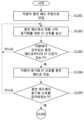
도 12a 및 12b는 본 발명의 일 실시예에 따른 위치 측정 방법의 순서도이다.
도 13은 본 발명의 일 실시예에 따라 차량이 정렬 범위 내에 위치하는지 판단하는 방법의 개념도이다.
도 14는 본 발명의 일 실시예에 따른 위치 측정 장치의 블록 구성도이다.1 is a conceptual diagram illustrating the concept of wireless power transmission for an electric vehicle to which an embodiment of the present invention is applied.
Figure 2 is a conceptual diagram illustrating an electric vehicle wireless charging circuit according to an embodiment of the present invention.
Figure 3 is a conceptual diagram illustrating the concept of alignment in electric vehicle wireless power transmission according to an embodiment of the present invention.
Figure 4 is a diagram showing a charging pad and an electric vehicle according to an embodiment of the present invention.
Figure 5 is a diagram showing power flow in wireless power transmission according to an embodiment of the present invention.
6 shows a power transmitter and power receiver circuit performing wireless power.
Figure 7 is a diagram showing the read range for each signal having various frequencies.
Figure 8 is a conceptual diagram of position alignment for wireless charging of a vehicle.
Figure 9 shows an example of LF antenna alignment between a power supply side device and a vehicle.
Figure 10 is a diagram for explaining a method of determining transmission intensity according to an embodiment of the present invention.
Figure 11 is a diagram showing transmission intensity and reception values that vary depending on the location of the vehicle according to an embodiment of the present invention.
12A and 12B are flowcharts of a position measurement method according to an embodiment of the present invention.
Figure 13 is a conceptual diagram of a method for determining whether a vehicle is located within an alignment range according to an embodiment of the present invention.
Figure 14 is a block diagram of a position measurement device according to an embodiment of the present invention.
본 발명은 다양한 변경을 가할 수 있고 여러 가지 실시예를 가질 수 있는 바, 특정 실시예들을 도면에 예시하고 상세한 설명에 상세하게 설명하고자 한다. 그러나, 이는 본 발명을 특정한 실시 형태에 대해 한정하려는 것이 아니며, 본 발명의 사상 및 기술 범위에 포함되는 모든 변경, 균등물 내지 대체물을 포함하는 것으로 이해되어야 한다. 각 도면을 설명하면서 유사한 참조부호를 유사한 구성요소에 대해 사용하였다.Since the present invention can make various changes and have various embodiments, specific embodiments will be illustrated in the drawings and described in detail in the detailed description. However, this is not intended to limit the present invention to specific embodiments, and should be understood to include all changes, equivalents, and substitutes included in the spirit and technical scope of the present invention. While describing each drawing, similar reference numerals are used for similar components.
제1, 제2, A, B 등의 용어는 다양한 구성요소들을 설명하는 데 사용될 수 있지만, 상기 구성요소들은 상기 용어들에 의해 한정되어서는 안 된다. 상기 용어들은 하나의 구성요소를 다른 구성요소로부터 구별하는 목적으로만 사용된다. 예를 들어, 본 발명의 권리 범위를 벗어나지 않으면서 제1 구성요소는 제2 구성요소로 명명될 수 있고, 유사하게 제2 구성요소도 제1 구성요소로 명명될 수 있다. "및/또는"이라는 용어는 복수의 관련된 기재된 항목들의 조합 또는 복수의 관련된 기재된 항목들 중의 어느 항목을 포함한다.Terms such as first, second, A, B, etc. may be used to describe various components, but the components should not be limited by the terms. The above terms are used only for the purpose of distinguishing one component from another. For example, a first component may be named a second component, and similarly, the second component may also be named a first component without departing from the scope of the present invention. The term “and/or” includes any of a plurality of related stated items or a combination of a plurality of related stated items.
어떤 구성요소가 다른 구성요소에 "연결되어" 있다거나 "접속되어" 있다고 언급된 때에는, 그 다른 구성요소에 직접적으로 연결되어 있거나 또는 접속되어 있을 수도 있지만, 중간에 다른 구성요소가 존재할 수도 있다고 이해되어야 할 것이다. 반면에, 어떤 구성요소가 다른 구성요소에 "직접 연결되어" 있다거나 "직접 접속되어" 있다고 언급된 때에는, 중간에 다른 구성요소가 존재하지 않는 것으로 이해되어야 할 것이다.When a component is said to be "connected" or "connected" to another component, it is understood that it may be directly connected to or connected to the other component, but that other components may exist in between. It should be. On the other hand, when it is mentioned that a component is “directly connected” or “directly connected” to another component, it should be understood that there are no other components in between.
본 출원에서 사용한 용어는 단지 특정한 실시예를 설명하기 위해 사용된 것으로, 본 발명을 한정하려는 의도가 아니다. 단수의 표현은 문맥상 명백하게 다르게 뜻하지 않는 한, 복수의 표현을 포함한다. 본 출원에서, "포함하다" 또는 "가지다" 등의 용어는 명세서상에 기재된 특징, 숫자, 단계, 동작, 구성요소, 부품 또는 이들을 조합한 것이 존재함을 지정하려는 것이지, 하나 또는 그 이상의 다른 특징들이나 숫자, 단계, 동작, 구성요소, 부품 또는 이들을 조합한 것들의 존재 또는 부가 가능성을 미리 배제하지 않는 것으로 이해되어야 한다.The terms used in this application are only used to describe specific embodiments and are not intended to limit the invention. Singular expressions include plural expressions unless the context clearly dictates otherwise. In this application, terms such as “comprise” or “have” are intended to designate the presence of features, numbers, steps, operations, components, parts, or combinations thereof described in the specification, but are not intended to indicate the presence of one or more other features. It should be understood that it does not exclude in advance the possibility of the existence or addition of elements, numbers, steps, operations, components, parts, or combinations thereof.
다르게 정의되지 않는 한, 기술적이거나 과학적인 용어를 포함해서 여기서 사용되는 모든 용어들은 본 발명이 속하는 기술 분야에서 통상의 지식을 가진 자에 의해 일반적으로 이해되는 것과 동일한 의미를 가지고 있다. 일반적으로 사용되는 사전에 정의되어 있는 것과 같은 용어들은 관련 기술의 문맥 상 가지는 의미와 일치하는 의미를 가지는 것으로 해석되어야 하며, 본 출원에서 명백하게 정의하지 않는 한, 이상적이거나 과도하게 형식적인 의미로 해석되지 않는다.Unless otherwise defined, all terms used herein, including technical or scientific terms, have the same meaning as commonly understood by a person of ordinary skill in the technical field to which the present invention pertains. Terms defined in commonly used dictionaries should be interpreted as having a meaning consistent with the meaning in the context of the related technology, and should not be interpreted in an ideal or excessively formal sense unless explicitly defined in the present application. No.
본 명세서에 사용되는 일부 용어를 정의하면 다음과 같다.Some terms used in this specification are defined as follows.
전기차(Electric Vehicle, EV)는 49 CFR(code of federal regulations) 523.3 등에서 정의된 자동차(automobile)를 지칭할 수 있다. 전기차는 고속도로 이용 가능하고, 차량 외부의 전원공급원으로부터 재충전 가능한 배터리 등의 차량 탑재 에너지 저장 장치에서 공급되는 전기에 의해 구동될 수 있다. 전원공급원은 주거지나 공용 전기서비스 또는 차량 탑재 연료를 이용하는 발전기 등을 포함할 수 있다.Electric Vehicle (EV) may refer to an automobile defined in 49 CFR (code of federal regulations) 523.3, etc. Electric vehicles can be used on highways and can be driven by electricity supplied from a vehicle-mounted energy storage device, such as a rechargeable battery from a power source external to the vehicle. Power sources may include residential or public electric services or vehicle-mounted fuel-fired generators.
전기차(electric vehicle, EV)는 일렉트릭 카(electric car), 일렉트릭 오토모바일(electric automobile), ERV(electric road vehicle), PV(plug-in vehicle), xEV(plug-in vehicle) 등으로 지칭될 수 있고, xEV는 BEV(plug-in all-electric vehicle 또는 battery electric vehicle), PEV(plug-in electric vehicle), HEV(hybrid electric vehicle), HPEV(hybrid plug-in electric vehicle), PHEV(plug-in hybrid electric vehicle) 등으로 지칭되거나 구분될 수 있다.An electric vehicle (EV) may be referred to as an electric car, electric automobile, electric road vehicle (ERV), plug-in vehicle (PV), plug-in vehicle (xEV), etc. xEV is BEV (plug-in all-electric vehicle or battery electric vehicle), PEV (plug-in electric vehicle), HEV (hybrid electric vehicle), HPEV (hybrid plug-in electric vehicle), and PHEV (plug-in electric vehicle). hybrid electric vehicle), etc.
플러그인 전기차(Plug-in Electric Vehicle, PEV)는 전력 그리드에 연결하여 량 탑재 일차 배터리를 재충전하는 전기차로 지칭될 수 있다.A plug-in electric vehicle (PEV) can be referred to as an electric vehicle that connects to the power grid to recharge its on-board primary battery.
플러그인 차량(Plug-in vehicle, PV)은 본 명세서에서 전기차 전력공급장치(electric vehicle supply equipment, EVSE)로부터 물리적인 플러그와 소켓을 사용하지 않고 무선 충전 방식을 통해 재충전 가능한 차량으로 지칭될 수 있다.A plug-in vehicle (PV) may be referred to herein as a vehicle that can be recharged through a wireless charging method from electric vehicle supply equipment (EVSE) without using a physical plug or socket.
중량 자동차(Heavy duty vehicles; H.D. Vehicles)는 49 CFR 523.6 또는 CFR 37.3(bus)에서 정의된 네 개 이상의 바퀴를 가진 모든 차량을 지칭할 수 있다.Heavy duty vehicles (H.D. Vehicles) may refer to any vehicle with four or more wheels as defined in 49 CFR 523.6 or CFR 37.3 (bus).
경량 플러그인 전기차(Light duty plug-in electric vehicle)는 주로 공공 거리, 도로 및 고속도로에서 사용하기 위한 재충전 가능한 배터리나 다른 에너지 장치의 전류가 공급되는 전기 모터에 의해 추진력을 얻는 3개 또는 4개 바퀴를 가진 차량을 지칭할 수 있다. 경량 플러그인 전기차는 총 중량이 4.545㎏보다 작게 규정될 수 있다.Light duty plug-in electric vehicle is a vehicle with three or four wheels powered by an electric motor supplied with current from a rechargeable battery or other energy device, primarily for use on public streets, roads and highways. It can refer to a vehicle you have. A lightweight plug-in electric vehicle can be defined as having a total weight of less than 4.545 kg.
무선 충전 시스템(Wireless power charging system, WCS)은 무선 전력 전송과 얼라인먼트 및 통신을 포함한 GA와 VA 간의 제어를 위한 시스템을 지칭할 수 있다.A wireless power charging system (WCS) may refer to a system for wireless power transmission and control between GA and VA, including alignment and communication.
무선 전력 전송(Wireless power transfer, WPT)은 유틸리티(Utility)나 그리드(Grid) 등의 교류(AC) 전원공급 네트워크에서 전기차로 무접촉 수단을 통해 전기적인 전력을 전송하는 것을 지칭할 수 있다.Wireless power transfer (WPT) can refer to the transfer of electrical power from an alternating current (AC) power supply network, such as a utility or grid, to an electric vehicle through contactless means.
유틸리티(Utility)는 전기적인 에너지를 제공하며 통상 고객 정보 시스템(Customer Information System, CIS), 양방향 검침 인프라(Advanced Metering Infrastructure, AMI), 요금과 수익(Rates and Revenue) 시스템 등을 포함하는 시스템들의 집합으로 지칭될 수 있다. 유틸리티는 가격표 또는 이산 이벤트(discrete events)를 통해 플러그인 전기차가 에너지를 이용할 수 있도록 한다. 또한, 유틸리티는 관세율, 계측 전력 소비에 대한 인터벌 및 플러그인 전기차에 대한 전기차 프로그램의 검증 등에 대한 정보를 제공할 수 있다.A utility provides electrical energy and is usually a set of systems that include a Customer Information System (CIS), Advanced Metering Infrastructure (AMI), and Rates and Revenue system. It may be referred to as . Utilities make energy available to plug-in electric vehicles through price tags or discrete events. Additionally, utilities can provide information on tariff rates, intervals for metered power consumption, and validation of electric vehicle programs for plug-in electric vehicles.
스마트 충전(Smart charging)은 EVSE 및/또는 플러그인 전기차가 차량 충전율이나 방전율을 그리드 용량이나 사용 비용 비율의 시간을 최적화하기 위해 전력 그리드와 통신하는 시스템으로 설명할 수 있다.Smart charging can be described as a system where EVSE and/or plug-in electric vehicles communicate with the power grid to optimize the vehicle charge or discharge rate to grid capacity or time-of-use cost ratio.
자동 충전(Automatic charging)은 전력을 전송할 수 있는 1차측 충전기 어셈블리(primary charger assembly)에 대하여 적절한 위치에 차량을 위치시키고 인덕티브 충전하는 동작으로 정의될 수 있다. 자동 충전은 필요한 인증 및 권한을 얻은 후에 수행될 수 있다.Automatic charging can be defined as the operation of placing a vehicle in an appropriate position and inductively charging it with respect to a primary charger assembly capable of transmitting power. Automatic recharge can be performed after obtaining the necessary authentication and permissions.
상호운용성(Interoperabilty)은 서로 상대적인 시스템의 성분들이 전체 시스템의 목적하는 동작을 수행하기 위해 함께 작동할 수 있는 상태를 지칭할 수 있다. 정보 상호운용성(Information interoperability)은 두 개 이상의 네트워크들, 시스템들, 디바이스들, 애플리케이션들 또는 성분들이 사용자가 거의 또는 전혀 불편함 없이 안전하고 효과적으로 정보를 공유하고 쉽게 사용할 수 있는 능력을 지칭할 수 있다.Interoperability can refer to a state in which components of a system relative to each other can work together to perform the desired operation of the overall system. Information interoperability can refer to the ability of two or more networks, systems, devices, applications or components to share and easily use information securely and effectively with little or no inconvenience to users. .
유도 충전 시스템(Inductive charging system)은 두 파트가 느슨하게 결합된 트랜스포머를 통해 전기 공급 네트워크에서 전기차로 정방향에서 전자기적으로 에너지를 전송하는 시스템을 지칭할 수 있다. 본 실시예에서 유도 충전 시스템은 전기차 충전 시스템에 대응할 수 있다.An inductive charging system can refer to a system that electromagnetically transfers energy in the forward direction from the electricity supply network to an electric vehicle through a transformer in which the two parts are loosely coupled. In this embodiment, the inductive charging system may correspond to an electric vehicle charging system.
유도 커플러(Inductive coupler)는 GA 코일과 VA 코일로 형성되어 전력이 전기적인 절연을 통해 전력을 전송하는 트랜스포머를 지칭할 수 있다.An inductive coupler may refer to a transformer that is formed of a GA coil and a VA coil and transmits power through electrical insulation.
유도 결합(Inductive coupling)은 두 코일들 간의 자기 결합을 지칭할 수 있다. 두 코일은 그라운드 어셈블리 코일(Ground assembly coil)과 차량 어셈블리 코일(Vehicle assembly coil)을 지칭할 수 있다.Inductive coupling can refer to magnetic coupling between two coils. The two coils may refer to a ground assembly coil and a vehicle assembly coil.
그라운드 어셈블리(Ground assembly, GA)는 GA 코일과 다른 적절한 부품을 포함하여 그라운드 또는 인프라스트럭처(infrastructure) 측에 배치되는 어셈블리를 지칭할 수 있다. 다른 적절한 부품은 임피던스와 공진주파수를 제어하기 위한 적어도 하나의 부품, 자기 경로(magnetic path)를 강화하기 위한 페라이트 및 전자기 차폐 재료를 포함할 수 있다. 예컨대, GA는 무선 충전 시스템의 전력 소스로서 기능하는 데 필요한 전력/주파수 변환 장치, GA 컨트롤러 및 그리드로부터의 배선과 각 유닛과 필터링 회로들, 하우징 등의 사이의 배선을 포함할 수 있다.Ground assembly (GA) may refer to an assembly that includes a GA coil and other suitable components and is placed on the ground or infrastructure side. Other suitable components may include at least one component to control the impedance and resonant frequency, a ferrite to strengthen the magnetic path, and an electromagnetic shielding material. For example, the GA may include wiring from the power/frequency conversion device, GA controller, and grid necessary to function as a power source for the wireless charging system, and wiring between each unit and filtering circuits, housing, etc.
차량 어셈블리(Vehicle assembly, VA)는 VA 코일과 다른 적절한 부품을 포함하여 차량에 배치되는 어셈블리를 지칭할 수 있다. 다른 적절한 부품은 임피던스와 공진주파수를 제어하기 위한 적어도 하나의 부품, 자기 경로를 강화하기 위한 페라이트 및 전자기 차폐 재료를 포함할 수 있다. 예를 들면, VA는 무선 충전 시스템의 차량 부품으로서 기능하는 데 필요한 정류기/전력변환장치와 VA 컨트롤러 및 차량 배터리의 배선뿐 아니라 각 유닛과 필터링 회로들, 하우징 등의 사이의 배선을 포함할 수 있다.Vehicle assembly (VA) may refer to an assembly that is placed in a vehicle, including VA coils and other suitable components. Other suitable components may include at least one component to control the impedance and resonant frequency, a ferrite to strengthen the magnetic path, and an electromagnetic shielding material. For example, VA may include wiring between each unit and filtering circuits, housing, etc., as well as wiring for the rectifier/power converter, VA controller, and vehicle battery required to function as a vehicle component of the wireless charging system. .
전술한 GA는 서플라이 디바이스(supply device), 전력공급측 장치 등으로 지칭될 수 있고, 이와 유사하게 VA는 전기차 디바이스(EV device), 전기차량 측 장치 등으로 지칭될 수 있다.The GA described above may be referred to as a supply device, a power supply side device, etc., and similarly, VA may be referred to as an electric vehicle device (EV device), an electric vehicle side device, etc.
전력공급측 장치(supply device)는 전기차량측 장치에 무접촉 결합을 제공하는 장치 즉, 전기차 외부의 장치일 수 있다. 전력 공급측 장치는 1차측 장치로 지칭될 수 있다. 전기차가 전력을 받을 때, 전력 공급측 장치는 전력을 전송하는 전원 소스로서 동작할 수 있다. 전력 공급측 장치는 하우징과 모든 커버들을 포함할 수 있다.The supply device may be a device that provides contactless coupling to the electric vehicle side device, that is, a device external to the electric vehicle. Power supply side devices may be referred to as primary side devices. When the electric vehicle receives power, the power supply side device can operate as a power source to transmit power. The power supply side device may include a housing and all covers.
전기차량측 장치(EV device)는 전력 공급측 장치에 무접촉 결합을 제공하는 전기차 탑재 장치일 수 있다. 전기차량측 장치는 2차측 장치로 지칭될 수 있다. 전기차가 전력을 받을 때, 전기차량측 장치는 전력공급측 장치로부터의 전력을 전기차로 전달할 수 있다. 전기차량측 장치는 하우징과 모든 커버들을 포함할 수 있다.An electric vehicle-side device (EV device) may be a device mounted on an electric vehicle that provides contactless coupling to a power supply-side device. Electric vehicle-side devices may be referred to as secondary-side devices. When the electric vehicle receives power, the device on the electric vehicle side can transmit power from the device on the power supply side to the electric vehicle. The electric vehicle side device may include a housing and all covers.
그라운드 어셈블리 컨트롤러(Ground Assembly controller)는 차량으로부터의 정보를 토대로 GA 코일에 대한 출력 전력 레벨을 조절하는 GA의 일부분일 수 있다.The Ground Assembly controller may be a part of the GA that adjusts the output power level to the GA coil based on information from the vehicle.
차량 어셈블리 컨트롤러(Vehicle Assembly controller)는 충전 동안 특정 차량용 파라미터를 모니터링하고 GA와의 통신을 개시하여 출력 전력 레벨을 제어하는 VA의 일부분일 수 있다.The Vehicle Assembly controller may be a part of the VA that monitors specific vehicle parameters during charging and initiates communication with the GA to control output power levels.
전술한 GA 컨트롤러는 전력공급측 장치의 서플라이 파워 서킷(supply power circuit, SPC)로 지칭될 수 있고, VA 컨트롤러는 전기차 파워 서킷(EV power circuit, EVPC)로 지칭될 수 있다.The GA controller described above may be referred to as a supply power circuit (SPC) of the power supply side device, and the VA controller may be referred to as an electric vehicle power circuit (EV power circuit, EVPC).
마그네틱 갭(Magnetic gap)은 리츠선(litz wire)의 상부 또는 GA 코일의 마그네틱 재료의 상부의 가장 높은 평면과 상기 리츠선의 하부 또는 VA 코일의 마그네틱 재료의 가장 낮은 평면이 서로 정렬되었을 때 이들 사이의 수직 거리를 지칭할 수 있다.Magnetic gap is the gap between the highest plane of the upper part of the litz wire or the magnetic material of the GA coil and the lowest plane of the lower part of the Litz wire or the magnetic material of the VA coil when they are aligned with each other. Can refer to vertical distance.
주위 온도(Ambient temperature)는 직접적으로 햇빛이 비치지 않는 대상 서브시스템의 대기에서 측정된 그라운드 레벨 온도를 지칭할 수 있다.Ambient temperature may refer to the ground level temperature measured in the atmosphere of the target subsystem outside of direct sunlight.
차량 지상고(Vehicle ground clearance)는 도로 또는 도로포장과 차량 플로어 팬의 최하부 사이의 수직 거리를 지칭할 수 있다.Vehicle ground clearance may refer to the vertical distance between the road or pavement and the bottom of the vehicle floor pan.
차량 마그네틱 지상고(Vehicle magnetic ground clearance)는 리츠선의 바닥 최하위 평면 또는 차량에 탑재된 VA 코일의 절연 재료와 도로포장 사이의 수직 거리를 지칭할 수 있다.Vehicle magnetic ground clearance may refer to the vertical distance between the lowest plane of the floor of the Litz wire or the insulating material of the VA coil mounted on the vehicle and the pavement.
차량 어셈블리(VA) 코일 표면 간격(Vehicle assembly coil surface distance)은 리츠선의 바닥 최하부의 평면 또는 VA 코일의 마그네틱 재료와 VA 코일의 최하위 외부 표면 사이의 수직 거리를 지칭할 수 있다. 이러한 거리는 보호 커버재 및 코일 포장재로 포장된 추가 아이템을 포함할 수 있다.Vehicle assembly (VA) coil surface distance may refer to the bottommost plane of the Litz wire or the vertical distance between the magnetic material of the VA coil and the lowest outer surface of the VA coil. This distance may include additional items packaged with protective covering material and coil packaging.
전술한 VA 코일은 2차 코일(secondary coil), 차량 코일(vehicle coil), 수신 코일(receiver coil) 등으로 지칭될 수 있고, 이와 유사하게 그라운드 어셈블리 코일(ground assembly coil, GA coil)은 1차 코일(primary coil), 송신 코일(transmit coil) 등으로 지칭될 수 있다.The aforementioned VA coil may be referred to as a secondary coil, vehicle coil, receiver coil, etc., and similarly, the ground assembly coil (GA coil) is the primary coil. It may be referred to as a primary coil, a transmit coil, etc.
노출 도전 부품(Exposed conductive component)은 사람에 의해 접촉될 수 있고 평상시 전기가 흐르지 않지만 고장 시에 전기가 흐를 수 있는 전기적인 장치(예컨대, 전기차)의 도전성 부품을 지칭할 수 있다.An exposed conductive component may refer to a conductive part of an electrical device (eg, an electric vehicle) that can be touched by a person and does not normally conduct electricity, but may conduct electricity in the event of a breakdown.
유해 라이브 요소(Hazardous live component)는 어떤 조건하에서 유해한 전기 쇼크를 줄 수 있는 라이브 구성요소를 지칭할 수 있다.Hazardous live component may refer to a live component that can deliver a harmful electric shock under certain conditions.
라이브 요소(Live component)는 기본적인 용도에서 전기적으로 활성화되는 모든 도체 또는 도전성 부품을 지칭할 수 있다.Live component can refer to any conductor or conductive component that is electrically active in its primary use.
직접 접촉(Direct contact)은 생물체인 사람의 접촉을 지칭할 수 있다.Direct contact may refer to contact between a living organism and a person.
간접 접촉(Indirect contact)은 절연 실패로 사람이 노출된, 도전된, 전기가 흐르는 활성 성분에 접촉하는 것을 지칭할 수 있다.(IEC 61140 참조)Indirect contact may refer to contact of a person with a live, conductive component that is exposed due to insulation failure (see IEC 61140).
얼라인먼트(Alignment)는 규정된 효율적인 전력 전송을 위해 전력공급측 장치에 대한 전기차량측 장치의 상대적인 위치를 찾는 절차 및/또는 전기차량측 장치에 대한 전력공급측 장치의 상대적인 위치를 찾는 절차를 가리킬 수 있다. 본 명세서에서 얼라인먼트는 무선 전력 전송 시스템의 위치 정렬을 지칭할 수 있으나, 이에 한정되지는 않는다.Alignment may refer to the process of locating an electric vehicle-side device relative to an electric vehicle-side device and/or the procedure of locating an electric vehicle-side device relative to an electric vehicle-side device for specified efficient power transfer. In this specification, alignment may refer to positional alignment of a wireless power transmission system, but is not limited thereto.
페어링(Pairing)은 전력을 전송할 수 있도록 배치된 단일 전용 그라운드 어셈블리(전력공급측 장치)와 차량(전기차)이 연관되는 절차를 지칭할 수 있다. 본 명세서에서 페어링은 충전 스팟 또는 특정 그라운드 어셈블리와 차량 어셈블리 제어기의 연관 절차를 포함할 수 있다. 연관(Correlation/Association)은 두 피어 통신 실체들 사이의 관계 성립 절차를 포함할 수 있다.Pairing can refer to the process of associating a vehicle (electric vehicle) with a single dedicated ground assembly (power supply side device) arranged to transmit power. In this specification, pairing may include an association procedure between a charging spot or a specific ground assembly and a vehicle assembly controller. Correlation/Association may include a procedure for establishing a relationship between two peer communication entities.
하이 레벨 통신(High level communication)은 명령 및 제어 통신에서 담당하는 정보를 초과하는 모든 정보를 처리할 수 있다. 하이 레벨 통신의 데이터 링크는 PLC(Power line communication)을 사용할 수 있으나, 이에 한정되지는 않는다.High level communication can handle all information that exceeds that covered by command and control communication. The data link for high-level communication may use PLC (Power line communication), but is not limited to this.
저전력 기동(Low power excitation)은 정밀 포지셔닝과 페어링을 수행하기 위해 전기차가 전력공급측 장치를 감지하도록 그것을 활성화하는 것을 지칭할 수 있으나, 이에 한정되지 않으며 그 역도 가능하다.Low power excitation may refer to, but is not limited to, activating an electric vehicle to detect a power supply side device to perform precise positioning and pairing, and vice versa.
SSID(Service set identifier)는 무선랜 상에서 전송되는 패킷의 해더에 붙는 32-character로 이루어진 유니크한 식별자이다. SSID는 무선 장비에서 접속하려고하는 BSS(basic service set)를 구분해준다. SSID는 기본적으로 여러 개의 무선랜을 서로 구별해준다. 따라서 특정한 무선랜을 사용하려는 모든 AP(access point)와 모든 단말(terminal)/스테이션(station) 장비들은 모두 같은 SSID를 사용할 수 있다. 유일한 SSID를 사용하지 않는 장비는 BSS에 조인하는 것이 불가능하다. SSID는 평문으로 그대로 보여지기 때문에 네트워크에 어떠한 보안 특성도 제공하지 않을 수 있다.SSID (Service set identifier) is a unique 32-character identifier attached to the header of packets transmitted over wireless LAN. SSID identifies the BSS (basic service set) that the wireless device is trying to connect to. SSID basically distinguishes multiple wireless LANs from each other. Therefore, all APs (access points) and all terminal/station devices that want to use a specific wireless LAN can all use the same SSID. Devices that do not use a unique SSID cannot join the BSS. Because the SSID is displayed as plain text, it may not provide any security properties to the network.
ESSID(Extended service set identifier)는 접속하고자 하는 네트워크의 이름이다. SSID와 비슷하지만 보다 확장된 개념일 수 있다.ESSID (Extended service set identifier) is the name of the network you want to connect to. It is similar to SSID, but may be a more expanded concept.
BSSID(Basic service set identifier)는 통상 48bits로 특정 BSS(basic service set)를 구분하기 위해 사용한다. 인프라스트럭쳐 BSS 네트워크의 경우, BSSID는 AP 장비의 MAC(medium access control)가 될 수 있다. 독립적인(independent) BSS나 애드훅(ad hoc) 네트워크의 경우, BSSID는 임의의 값으로 생성될 수 있다.BSSID (Basic service set identifier) is usually 48 bits and is used to identify a specific BSS (basic service set). For an infrastructure BSS network, the BSSID can be the MAC (medium access control) of the AP device. In the case of an independent BSS or ad hoc network, the BSSID can be generated with a random value.
차징 스테이션(charging station)은 적어도 하나 이상의 그라운드 어셈블리와 적어도 하나 이상의 그라운드 어셈블리를 관리하는 적어도 하나 이상의 그라운드 어셈블리 제어기를 포함할 수 있다. 그라운드 어셈블리는 적어도 하나 이상의 무선통신기를 구비할 수 있다. 차징 스테이션은 가정, 사무실, 공공장소, 도로, 주차장 등에 설치되는 적어도 하나 이상의 그라운드 어셈블리를 구비한 장소를 지칭할 수 있다.A charging station may include at least one ground assembly and at least one ground assembly controller that manages the at least one ground assembly. The ground assembly may be equipped with at least one wireless communicator. A charging station may refer to a place equipped with at least one ground assembly installed in homes, offices, public places, roads, parking lots, etc.
본 발명은 LF(Low-Frequency) 센서를 이용한 차량의 위치 추정 방법 및 장치에 관한 것으로, 더욱 상세하게는 전기 자동차와 충전 패드(pad) 간의 위치 정렬시 LF 센서를 이용하여 전기 자동차의 위치를 추정하는 방법 및 장치에 관한 것이다.The present invention relates to a method and device for estimating the position of a vehicle using a low-frequency (LF) sensor, and more specifically, to estimate the position of an electric vehicle using an LF sensor when aligning the position between an electric vehicle and a charging pad. It relates to a method and device for doing so.
이하, 본 발명에 따른 바람직한 실시예를 첨부된 도면을 참조하여 상세하게 설명한다.Hereinafter, preferred embodiments according to the present invention will be described in detail with reference to the attached drawings.
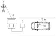
도 1은 본 발명의 일 실시예가 적용되는 전기차를 위한 무선 전력 전송의 개념을 설명하기 위한 개념도이다.1 is a conceptual diagram illustrating the concept of wireless power transmission for an electric vehicle to which an embodiment of the present invention is applied.
도 1을 참조하면, 무선 전력 전송은 전기차(electric vehicle, 10)의 적어도 하나의 구성요소와 차징 스테이션(charging station, 20)에 의해서 수행될 수 있고, 전기차(10)에 무선으로 전력을 전송하기 위해서 이용될 수 있다.Referring to FIG. 1, wireless power transmission may be performed by at least one component of an
여기서, 전기차(10)는 일반적으로 배터리(12)와 같이 충전 가능한 에너지 저장 장치로부터 유도된 전류를 동력장치인 전기 모터의 에너지원으로 공급하는 차량(automobile)으로 정의할 수 있다.Here, the
다만, 본 발명에 따른 전기차(10)는 전기 모터와 일반적인 내연기관(internal combustion engine)을 함께 갖는 하이브리드 자동차를 포함할 수 있고, 자동차(automobile)뿐만 아니라 모터사이클(motocycle), 카트(cart), 스쿠터(scooter) 및 전기 자전거(electric bicycle)를 포함할 수 있다.However, the
또한, 전기차(10)는 무선으로 배터리(12)를 충전할 수 있도록 수신 코일이 포함된 수신 패드(11)를 포함할 수 있으며, 유선으로 배터리(12)를 충전할 수 있도록 플러그 접속구를 포함할 수도 있다. 이때, 유선으로 배터리(12)를 충전할 수 있는 전기차(10)를 플러그인 전기차(Plug-in Electric Vehicle, PEV)로 지칭할 수 있다.In addition, the
여기서, 차징 스테이션(20)은 전력망(power grid, 30) 또는 전력 백본(power backbone)에 연결될 수 있고, 전력 링크(power link)를 통하여 송신 코일이 포함된 송신 패드(21)에 교류(AC) 또는 직류(DC) 전력을 제공할 수 있다.Here, the charging
또한, 차징 스테이션(20)은 유무선 통신을 통하여 전력망(power grid, 30) 또는 전력망을 관리하는 인프라 관리 시스템(infrastructure management system) 또는 인프라 서버와 통신할 수 있고, 전기차(10)와 무선 통신을 수행할 수 있다.In addition, the charging
여기서, 무선 통신에는 블루투스(Bluetooth), 지그비(zigbee), 셀룰러(cellular), 무선 로컬 영역 네트워크(wireless local area network) 등이 있을 수 있다.Here, wireless communication may include Bluetooth, zigbee, cellular, wireless local area network, etc.
또한, 예를 들어 차징 스테이션(20)은 전기차(10) 소유자의 집에 부속된 주차장, 주유소에서 전기차 충전을 위한 주차구역, 쇼핑 센터나 직장의 주차구역 등과 같이 다양한 장소에 위치할 수 있다.Additionally, for example, the charging
여기서, 전기차(10)의 배터리(12)를 무선 충전하는 과정은 먼저 전기차(10)의 수신 패드(11)가 송신 패드(21)에 의한 에너지 장(energy field)에 위치하고, 송신 패드(21)의 송신 코일과 수신 패드(11)의 수신 코일이 서로 상호작용 또는 커플링됨으로써 수행될 수 있다. 상호작용 또는 커플링의 결과로 수신 패드(11)에 기전력이 유도되고, 유도된 기전력에 의해 배터리(12)가 충전될 수 있다.Here, in the process of wirelessly charging the
또한, 차징 스테이션(20)과 송신 패드(21)는 그 전부 또는 일부를 그라운드 어셈블리(Ground Assembly, GA)로 지칭할 수 있고, 그라운드 어셈블리는 앞서 정의한 의미를 참조할 수 있다.In addition, the charging
또한, 전기차(10)의 수신 패드(11)와 전기차의 다른 내부 구성요소 전부 또는 일부를 차량 어셈블리(Vehicle Assembly, VA)로 지칭할 수 있는데, 여기서 차량 어셈블리는 앞서 정의한 의미를 참조할 수 있다.Additionally, the receiving
여기서, 송신 패드 또는 수신 패드는 비극성(non-polarized) 또는 극성(polarized)으로 구성될 수도 있다.Here, the transmitting pad or the receiving pad may be configured as non-polarized or polarized.
이때, 패드가 비극성이면 패드의 중앙에 하나의 극이 있고, 바깥 주변에 반대 극을 가질 수 있다. 여기서, 자속(flux)는 패드의 중앙에서 나가고(exit), 패드의 모든 바깥 경계에서 복귀(return)하도록 형성될 수 있다.At this time, if the pad is non-polar, there may be one pole in the center of the pad and the opposite pole around the outside. Here, the magnetic flux can be formed to exit from the center of the pad and return from all outer boundaries of the pad.
또한, 패드가 극성인 경우, 패드의 어느 한쪽 끝에 각각의 극을 가질 수 있다. 여기서, 자속은 패드의 방향(orientation)에 기초하여 형성될 수 있다.Additionally, if the pad is polarized, each pad may have a polarity at either end. Here, magnetic flux can be formed based on the orientation of the pad.
도 2는 본 발명의 일 실시예에 따른 전기차 무선 충전 회로를 도시한 개념도이다.Figure 2 is a conceptual diagram illustrating an electric vehicle wireless charging circuit according to an embodiment of the present invention.
도 2를 참조하면, 전기차 무선 충전 시스템에서 충전이 이루어지는 회로에 대한 개략적인 구성을 알 수 있다.Referring to FIG. 2, a schematic configuration of a charging circuit in an electric vehicle wireless charging system can be seen.
여기서, 도 2의 좌측 회로는 전력망에서 공급되는 전원(Vsrc), 도 1에서의 차징 스테이션(20), 송신 패드(21)의 구성 중 전부 또는 일부를 표현한 것으로 해석될 수 있고, 도 2의 우측 회로는 수신 패드 및 배터리를 포함한 전기차의 일부 또는 전부를 표현한 것으로 해석될 수 있다.Here, the circuit on the left side of FIG. 2 can be interpreted as representing all or part of the configuration of the power supply (Vsrc) supplied from the power grid, the charging
먼저, 도 2의 좌측 회로는 전력망에서 공급되는 전원(Vsrc)에 대응되는 출력 전력(Psrc)를 무선 충전 전력 변환기에 제공하고, 무선 충전 전력 변환기는 송신 코일(L1)에서 희망하는 공진 주파수에서의 전자기장을 방출할 수 있도록, 제공받은 전력(Psrc)의 주파수 및 AC/DC 변환을 수행한 전력(P1)을 출력할 수 있다.First, the left circuit of FIG. 2 provides output power (Psrc ) corresponding to power (Vsrc ) supplied from the power grid to the wireless charging power converter, and the wireless charging power converter provides the desired resonance in the transmitting coil (L1 ). In order to emit an electromagnetic field at a frequency, the frequency and AC/DC conversion of the provided power (Psrc ) and power (P1 ) can be output.
구체적으로, 무선 충전 전력 변환기는 전력망에서 공급된 전력(Psrc)이 AC 전력인 경우 DC 전력으로 변환하는 AC/DC 변환기 및 DC전력을 무선 충전에 적합한 공진 주파수의 전력으로 변환하는 저주파수 변환기(또는 LF 변환기) 중 적어도 하나를 포함할 수 있다. 공진 주파수는 예를 들면, 79 내지 90 kHz 사이에 위치하도록 결정할 수 있다.Specifically, the wireless charging power converter is an AC/DC converter that converts the power (Psrc ) supplied from the power grid into DC power when it is AC power, and a low-frequency converter (or LF converter). The resonant frequency may be determined to be located between, for example, 79 and 90 kHz.
무선 충전 전력 변환기에서 출력된 전력(P1)은 다시 송신 코일(L1), 제1 커패시터(C1) 및 제1 저항(R1)으로 구성된 회로에 공급될 수 있고, 이때 제1 커패시터(C1)는 송신 코일(L1)과 함께 충전에 적합한 공진 주파수를 갖도록 하는 소자값을 가지도록 결정될 수 있다. 또한, 여기서 제1 저항(R1)은 송신 코일(L1) 및 제1 커패시터(C1)에 의해 발생하는 전력손실을 의미할 수 있다.The power (P1 ) output from the wireless charging power converter may be supplied to a circuit consisting of a transmitting coil (L1 ), a first capacitor (C1 ), and a first resistor (R1 ), where the first capacitor ( C1 ) may be determined to have an element value that allows it to have a resonance frequency suitable for charging together with the transmission coil (L1 ). Additionally, here, the first resistance (R1 ) may refer to power loss generated by the transmission coil (L1 ) and the first capacitor (C1 ).
여기서, 송신 코일(L1)은 수신 코일(L2)과 커플링 계수 k으로 정의되는 전자기적 커플링이 이루어져 전력이 전송되도록 하거나, 또는 전력이 수신 코일(L2)로 유도될 수 있다. 따라서, 본 발명에서 전력이 전송된다는 의미는 전력이 유도된다는 의미와 혼용하여 사용될 수 있다.Here, the transmitting coil (L1 ) is electromagnetically coupled to the receiving coil (L2 ), defined by a coupling coefficient k, such that power is transmitted, or power can be induced into the receiving coil (L2 ). Therefore, in the present invention, the meaning of power being transmitted can be used interchangeably with the meaning of power being induced.
여기서, 수신 코일로 유도되거나 전송받은 전력(P2)은 전기차 전력 변환기로 제공될 수 있다. 이때, 제2 커패시터(C2)는 수신 코일(L2)과 함께 충전에 적합한 공진 주파수를 갖도록 하는 소자값으로 결정될 수 있고, 제2 저항(R2)은 수신 코일(L2) 및 제2 커패시터(C2)에 의해 발생하는 전력 손실을 의미할 수 있다.Here, the power (P2 ) induced or transmitted to the receiving coil may be provided to the electric vehicle power converter. At this time, the second capacitor (C2 ) may be determined to have an element value such that it has a resonance frequency suitable for charging together with the receiving coil (L2 ), and the second resistor (R2 ) may be determined to have a resonance frequency suitable for charging with the receiving coil (L2 ). This may mean power loss caused by the capacitor (C2 ).
전기차 전력 변환기는 제공받은 특정 공진 주파수의 전력(P2)을 다시 전기차의 배터리(VHV)에 적합한 전압 레벨을 갖는 DC 전력으로 변환하는 AC/DC 변환기를 포함할 수 있다.The electric vehicle power converter may include an AC/DC converter that converts the received power (P2 ) of a specific resonance frequency back into DC power having a voltage level suitable for the battery (VHV ) of the electric vehicle.
전기차 전력 변환기가 제공받은 전력(P2)을 변환한 전력(PHV)을 출력하면, 출력된 전력(PHV)는 전기차에 내장된 배터리(VHV)의 충전에 사용될 수 있다.When the electric vehicle power converter outputs power (PHV ) converted from the received power (P2 ), the output power (PHV ) can be used to charge the battery (VHV ) built into the electric vehicle.
여기서, 도 2의 우측 회로에는 수신 코일(L2)을 배터리(VHV)와 선택적으로 접속 또는 해제하기 위한 스위치(switch)를 더 포함할 수 있다.Here, the circuit on the right side of FIG. 2 may further include a switch for selectively connecting or disconnecting the receiving coil (L2 ) to the battery (VHV ).
여기서, 송신 코일(L1)과 수신 코일(L2)의 공진 주파수(resonance frequency)는 서로 유사하거나 동일하도록 구성될 수 있으며, 송신 코일(L1)에서 발생된 전자기장에 수신 코일(L2)이 근거리에 위치할 수 있도록 구성될 수 있다.Here, the resonance frequencies of the transmitting coil (L1 ) and the receiving coil (L2 ) may be configured to be similar or identical to each other, and the electromagnetic field generated by the transmitting coil (L1 ) may be applied to the receiving coil (L2 ). It can be configured to be located at a short distance.
여기서, 도 2의 회로는 본 발명의 실시예들을 위해서 이용 가능한 전기차 무선 충전 시스템에서의 전력 전송에 관한 예시적 회로로 이해되어야 하며, 도 2에서의 회로에 한정하여 해석되는 것은 아니다.Here, the circuit of FIG. 2 should be understood as an exemplary circuit related to power transmission in an electric vehicle wireless charging system usable for embodiments of the present invention, and is not interpreted as being limited to the circuit in FIG. 2.
한편, 송신 코일(L1)과 수신 코일(L2)이 원거리에 위치할수록 전력 손실이 증가할 수 있으므로, 양자의 위치를 설정하는 것은 중요한 요소일 수 있다.Meanwhile, power loss may increase as the transmitting coil (L1 ) and the receiving coil (L2 ) are located further apart, so setting the positions of both may be an important factor.
이때, 송신 코일(L1)은 도 1에서의 송신 패드(21)에 포함되고, 수신 코일(L2)은 도 1에서의 수신 패드(11)에 포함될 수 있다. 또한, 송신 코일은 GA 코일(Ground Assembly coil)로 지칭될 수도 있고, 수신 코일은 VA 코일(Vehicle Assembly coil)로 지칭될 수도 있다. 한편, 본 명세서에서는 설명의 편의상 필요에 따라, 송신 코일과 송신 패드를 기능상 동일한 의미로 사용하였다. 또한, 수신 코일과 수신 패드를 기능상 동일한 의미로 사용하였다.At this time, the transmitting coil (L1 ) may be included in the
따라서, 송신 패드와 수신 패드 상호간의 위치 결정 또는 전기차와 송신 패드 상호간의 위치 결정에 관하여 이하 도면을 참조하여 설명한다.Accordingly, positioning between a transmitting pad and a receiving pad or between an electric vehicle and a transmitting pad will be described with reference to the drawings below.
도 3은 본 발명의 일 실시예에 따른 전기차 무선 전력 전송에서의 정렬 개념을 설명하기 위한 개념도이다.Figure 3 is a conceptual diagram illustrating the concept of alignment in electric vehicle wireless power transmission according to an embodiment of the present invention.
도 3을 참조하면, 도 1에서의 송신 패드(21) 및 전기차(10)에 내장된 수신 패드(11) 사이의 위치 정렬 방법을 설명할 수 있다. 여기서, 위치 정렬은 앞서 설명한 용어인 얼라인먼트(alignment)에 대응될 수 있고, 따라서, GA와 VA간의 위치 정렬로 정의할 수도 있고, 송신 패드(21)와 수신 패드(11)의 위치 정렬로 한정해석되지 않는다.Referring to FIG. 3, a method of positioning alignment between the transmitting
여기서, 송신 패드(21)는 도 3에서는 지표면 아래에 위치한 것으로 도시하였으나, 지표면 위에 위치할 수도 있고, 지표면 아래에서 송신 패드(21)의 상면이 노출되도록 위치할 수도 있다.Here, the
또한, 전기차의 수신 패드(11)는 지표면을 기준으로 측정된 높이(z방향으로 정의)에 따라 카테고리를 달리하여 정의할 수 있고, 예를 들어 지표면에서 수신 패드(11)의 높이가 100-150(mm)인 경우 class 1, 140-210(mm) 인 경우 class 2, 170-250(mm)인 경우 class 3와 같이 설정할 수 있다. 이때, 수신 패드(11)에 따라 class 1만을 지원하거나, class 1과 2를 지원할 수도 있는 등 부분적 지원이 가능할 수 있다.In addition, the receiving
여기서, 지표면을 기준으로 측정된 높이는 앞서 설명한 용어인 차량 마그네틱 지상고에 대응될 수 있다.Here, the height measured relative to the ground surface may correspond to the vehicle magnetic ground clearance, which is a term described previously.
또한, 송신 패드(21)의 높이 방향(z 방향으로 정의)의 위치는 상기 수신 패드(11)에서 지원하는 최대 클래스와 최소 클래스 사이에 위치하도록 결정할 수 있는데, 예를 들어 수신 패드(11)가 class1과 2만을 지원한다면, 수신 패드(11)를 기준으로 100-210 (mm) 사이에 송신 패드가 위치하도록 결정할 수 있다.Additionally, the position of the transmitting
또한, 송신 패드(21)의 중심과 수신 패드(11)의 중심 사이의 격차는 가로 및 세로 방향의 한계값 이내에 위치하도록 결정할 수 있다. 예를 들어, 가로 방향(+y 방향 또는 차량 진행 방향의 우측 수직 방향으로 정의)으로는 ±75 (mm) 이내에 위치하도록 결정할 수 있고, 세로 방향(-x방향 또는 차량 진행 방향으로 정의)으로는 ±100 (mm) 이내에 위치하도록 결정할 수 있다.Additionally, the gap between the center of the transmitting
여기서, 송신 패드(21)와 수신 패드(11)의 상대적 위치는 그 실험적 결과에 따라 한계값이 달라질 수 있고, 상기 수치들은 예시적인 것으로 이해되어야 한다.Here, the relative positions of the transmitting
또한, 송신 패드(21)와 수신 패드(11)는 각각 코일을 포함하는 것으로 전제하고 패드 상호간의 정렬로 설명하였으나, 더 구체적으로는 송신 패드(21)와 수신 패드(11)에 각각 내장된 송신 코일(또는 GA 코일)과 수신 코일(또는 VA 코일) 상호간의 정렬로 정의할 수도 있다.In addition, the
한편, 전기차 무선충전시 충전효율 극대화를 위해 1차측 코일(GA Coil)과 2차측 코일(VA Coil)의 정렬에 LF(Low Frequency) 신호가 사용될 수 있다. LF 신호는 매우 낮은 주파수 및 낮은 주파수의 ITU 무선 대역에서 동작하는 디지털 변조된 자기장(digitally modulated magnetic field)이다. LF 센서는 19kHz 내지 300kHz 의 주파수 범위 내의 고정된 주파수에서 동작할 수 있다.Meanwhile, in order to maximize charging efficiency when wirelessly charging electric vehicles, the LF (Low Frequency) signal can be used to align the primary coil (GA Coil) and secondary coil (VA Coil). LF signals are digitally modulated magnetic fields that operate in the very low and low frequency ITU radio bands. LF sensors can operate at a fixed frequency within the frequency range of 19 kHz to 300 kHz.
또한, 자기장은 EV에 위치하는 적어도 2개의 안테나에 의해 생성될 수 있다. EV에 위치하는 LF 안테나 배치는 예를 들어, 아래 도 8에 도시된 바와 같은 위치들일 수 있지만, 이러한 실시예에 의해 제한되지 않는다. 추가적으로, 1차측 디바이스는 적어도 2개의 자기 센서들을 포함할 수 있으며, 자기 센서의 센싱 엘리먼트들은 대칭적으로 배치되는 것이 바람직하다. 자기 센서들은 자기장의 세기를 x, y, z 방향에서 수신할 수 있다.Additionally, the magnetic field may be generated by at least two antennas located in the EV. LF antenna placement located in the EV may be, for example, locations as shown in Figure 8 below, but is not limited by this embodiment. Additionally, the primary device may include at least two magnetic sensors, and the sensing elements of the magnetic sensors are preferably arranged symmetrically. Magnetic sensors can receive magnetic field strength in the x, y, and z directions.
한편, 자율주행 기술을 접목하여 자율주차 또는 원격주차를 이용한 위치정렬 또한 고려되고 있다.Meanwhile, location alignment using autonomous or remote parking by incorporating autonomous driving technology is also being considered.
또한, 전기차 충전 통신 표준 문서인 ISO 15118-8에 따르면, 전기차 충전을 위한 무선통신을 사용 시 차량측 통신 제어기(EVCC, Electric Vehicle Communication Controller)와 전력 공급측 통신 제어기(SECC, Supply Equipment Communication Controller) 사이의 통신 규격은 IEEE Std 802.11-2012를 준수한다. 무선통신에서 고려되는 통신 채널을 위한 EVCC 및 SECC 간의 거리에 대한 요구 범위는 디스커버리(Discovery)의 경우 5m~30m, 정밀 포지셔닝(Fine positioning)의 경우 10cm~5m, 충전 제어(Charge control)의 경우 5cm~5m이다.In addition, according to ISO 15118-8, an electric vehicle charging communication standard document, when using wireless communication for electric vehicle charging, there is a communication between the vehicle communication controller (EVCC, Electric Vehicle Communication Controller) and the power supply communication controller (SECC, Supply Equipment Communication Controller). The communication standard complies with IEEE Std 802.11-2012. The required range for the distance between EVCC and SECC for communication channels considered in wireless communication is 5m to 30m for discovery, 10cm to 5m for fine positioning, and 5cm for charge control. It is ~5m.
여기서, 디스커버리는 전기차가 충전 패드를 탐색하는 단계로, EVCC가 SECC의 통신 범위에 진입하고 적절한 SECC와 연결하는 단계이다. 정밀 포지셔닝은 WPT의 경우 효율적인 전력 전송을 위한 1차측 및 2차측 디바이스들 간의 정렬을, 도전성 충전을 위한 자동 연결의 경우 전력 전송을 위해 EV 및 EVSE의 커넥터들의 정렬을 의미할 수 있다. 충전 제어는 예를 들어, 차량으로부터 EVSE로의 전력 요청 등이 형태일 수 있다.Here, discovery is the stage where the electric vehicle searches for a charging pad, and the EVCC enters the communication range of the SECC and connects with the appropriate SECC. Precision positioning can mean alignment between primary and secondary devices for efficient power transfer in the case of WPT, and alignment of connectors of EV and EVSE for power transfer in the case of automatic connection for conductive charging. Charging control may take the form of, for example, a power request from the vehicle to the EVSE.
도 4는 본 발명의 일 실시예에 따른 충전 패드 및 전기차를 나타낸 도면이다.Figure 4 is a diagram showing a charging pad and an electric vehicle according to an embodiment of the present invention.
본 발명은 무선 전력 수신기에 대한 무선 전력 송신기의 상대적인 위치를 결정하기 위한 방법에 관한 것이다. 무선 전력 송신기와 무선 전력 수신기 사이의 거리 또는 방향은 무선 전력 송신기 또는 무선 전력 수신기에서 발생되는 자기장을 검출함으로써 결정될 수 있고, 그에 따라 수신기 및 송신기 간의 상대적인 위치를 판단할 수 있다.The present invention relates to a method for determining the relative position of a wireless power transmitter with respect to a wireless power receiver. The distance or direction between the wireless power transmitter and the wireless power receiver can be determined by detecting a magnetic field generated from the wireless power transmitter or the wireless power receiver, and the relative position between the receiver and the transmitter can be determined accordingly.
도 4에 도시된 바와 같이, 전력 송신기(송신 패드; 21)에 4개의 LF 안테나(P1, P2, P3, P4)를 장착하고, 전력 수신기(수신 패드)에 2개의 LF 안테나(V1, V2)를 배치함으로써, 차량이 정 위치에 위치하고 있는지를 확인할 수 있도록 하는 기술이 논의되고 있었다.As shown in Figure 4, four LF antennas (P1, P2, P3, P4) are mounted on the power transmitter (transmitting pad; 21), and two LF antennas (V1, V2) are mounted on the power receiver (receiving pad). A technology was being discussed to ensure that the vehicle is in the correct position by placing a .
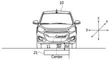
도 5는 본 발명의 일 실시예에 따른 무선 전력 전송에서의 전력 흐름을 나타낸 도면이다.Figure 5 is a diagram showing power flow in wireless power transmission according to an embodiment of the present invention.
도 5를 참조하면, 전력은 충전 패드로부터 전기차로 송신됨을 알 수 있다. 다만, 이는 가시화를 위해 가상으로 나타낸 전력 흐름일 뿐, 도시된 내용이 본 발명을 한정한하는 것은 아니다.Referring to Figure 5, it can be seen that power is transmitted from the charging pad to the electric vehicle. However, this is only a virtual power flow for visualization, and the depicted content does not limit the present invention.
또한, 도 5에서 도시된 바와 같이, 본 발명의 일 실시예에 따른 전기차의 LF 안테나(V1, V2)는 충전 패드의 좌우 또는 상하에 대응하는 위치에 대칭되게 위치할 수 있다.Additionally, as shown in FIG. 5, the LF antennas V1 and V2 of the electric vehicle according to an embodiment of the present invention may be symmetrically positioned at positions corresponding to the left and right or top and bottom of the charging pad.
도 6은 무선 전력을 수행하는 전력 송신기 및 전력 수신기 회로를 도시한 다.6 shows a power transmitter and power receiver circuit performing wireless power.
도 6을 참조하면, 수신기(receiver)(610)는 수신 코일(receiver coil), 배터리(battery), 배터리 충전기(battery charger), 정류기(rectifier), 필터(filter) 및 수신 제어기(rx control)를 포함하여 구성될 수 있다.Referring to FIG. 6, the receiver 610 includes a receiver coil, battery, battery charger, rectifier, filter, and rx control. It can be configured to include.
송신기(transmitter)(620)는 송신 코일(transmitter coil), DC 전압 공급기, 반-브릿지(half-bridge) 회로 및 송신 제어기(tx control)를 포함하여 구성될 수 있다.The transmitter 620 may be configured to include a transmitter coil, a DC voltage supply, a half-bridge circuit, and a transmit controller (tx control).
도 7은 다양한 주파수를 가지는 신호별 판독 범위를 나타낸 도면이다.Figure 7 is a diagram showing the read range for each signal having various frequencies.
도 7을 참조하면, LF 및 수동형 HF를 이용하는 경우, 인근 거리에서 판독 가능할 수 있다. 또한, 수동형 UHF를 이용하는 경우, 원거리에서 판독 가능할 수 있으며, 능동형 UHF를 이용하는 경우, 능동형 테크에 따라 원거리보다 상대적으로 더욱 긴 거리에서 판독 가능할 수 있다.Referring to FIG. 7, when using LF and passive HF, reading may be possible from a nearby distance. Additionally, when using passive UHF, it may be possible to read from a long distance, and when using active UHF, it may be possible to read from a relatively longer distance depending on the active technology.
그런데, LF 센서의 특성상 수신기와 송신기가 일정 수준이상 근접하게 되면 신호 포화로 인해 정확한 거리를 감지하지 못하는 한계를 가지고 있다. 따라서, 본 발명은 LF 신호를 이용한 위치 정렬시 신호 포화의 한계를 해결하고자 한다.However, due to the characteristics of the LF sensor, it has the limitation of not being able to detect the exact distance due to signal saturation when the receiver and transmitter are closer than a certain level. Therefore, the present invention seeks to solve the limitation of signal saturation when aligning positions using an LF signal.
도 8은 차량의 무선 충전을 위한 위치 정렬의 개념도이다.Figure 8 is a conceptual diagram of position alignment for wireless charging of a vehicle.
도 8을 참조하면, 무선 충전을 위한 위치 정렬 방법은 그라운드 어셈블리(GA)의 1차 코일 및 차량 어셈블리(VA)의 2차 코일의 위치를 정렬하여 무선 충전 효율을 극대화 및/또는 최적화하기 위한 방법으로, GA 측의 4개의 안테나(ANT1, ANT2, ANT3 및 ANT4) 및 VA 측의 2개의 안테나(ANTa 및 ANTb) 간의 자기장 측정치를 기초로 수행될 수 있다.Referring to FIG. 8, the position alignment method for wireless charging is a method for maximizing and/or optimizing wireless charging efficiency by aligning the positions of the primary coil of the ground assembly (GA) and the secondary coil of the vehicle assembly (VA). It can be performed based on magnetic field measurements between four antennas (ANT1, ANT2, ANT3 and ANT4) on the GA side and two antennas (ANTa and ANTb) on the VA side.
더욱 상세하게는, VA는 2개의 안테나를 포함할 수 있고, 2개의 안테나는 VA의 좌측 구역 및 우측 구역에 하나씩 위치할 수 있으며, 좌측 구역 및 우측 구역은 VA를 좌측 및 우측으로 2등분한 구역을 의미할 수 있고, 좌우 대칭적으로 구분한 구역을 의미할 수 있다. VA가 사각형의 구조를 가지는 경우, 2개의 안테나는 사각형의 좌측변 중앙 및 우측변 중앙에 각각 위치할 수 있으나, 구조는 설계에 따라 변경될 수 있으므로, 사각형으로 한정하지 않는다.More specifically, the VA may include two antennas, and the two antennas may be located one in a left zone and one in a right zone of the VA, where the left zone and the right zone are a zone that divides the VA into left and right halves. It can mean , and it can mean a symmetrically divided area. If the VA has a rectangular structure, the two antennas can be located in the center of the left side and the center of the right side of the rectangle, respectively, but the structure may change depending on the design, so it is not limited to a rectangular shape.
또한, 2개의 안테나는 VA와 연결되어 차량의 특정 부분에 위치할 수도 있으며, 이러한 경우 차량의 특정 부분의 좌측 구역 및 우측 구역에 하나씩 위치할 수 있다. 차량의 특정 부분의 좌측 구역 및 우측 구역은 차량의 특정 부분을 좌우 대칭적으로 구분한 구역을 의미할 수 있다.Additionally, the two antennas may be connected to the VA and located in a specific part of the vehicle. In this case, the two antennas may be located one in the left area and one in the right area of the specific part of the vehicle. The left area and right area of a specific part of the vehicle may refer to areas in which the specific part of the vehicle is symmetrically divided into left and right sides.
상술한 VA 및 차량의 특정 부분의 좌측 구역 및 우측 구역은 앞쪽 구역 및 뒤쪽 구역도 될 수 있으나, 이에 한정하지 않으며, 대칭성을 가지고 구분된 2개의 구역을 의미할 수 있다. 이하에서는 VA에 위치하는 것으로 가정하여 설명하겠다.The left and right zones of the VA and specific parts of the vehicle described above may also be the front zone and the rear zone, but are not limited thereto, and may mean two zones divided with symmetry. Hereinafter, the explanation will be made assuming that it is located in VA.
VA 또는 차량 어셈블리 컨트롤러(vehicle assembly controller)는 안테나를 제어할 수 있고, VA 및 GA 간의 위치 차이 정보를 산출할 수 있다.The VA or vehicle assembly controller can control the antenna and calculate position difference information between the VA and GA.
GA는 4개의 안테나를 포함할 수 있고, 4개의 안테나는 GA의 제1 구역, 제2 구역, 제3 구역 및 제 4구역에 하나씩 위치할 수 있으며, 제1 구역, 제2 구역, 제3 구역 및 제4 구역은 각각 GA의 좌측 상단 구역, 우측 상단 구역, 좌측 하단 구역 및 우측 하단 구역을 의미할 수 있으나, 이에 한정하지 않으며, GA를 동일한 크기를 가지도록 4등분한 구역들을 각각 의미할 수 있다. GA가 사각형의 구조를 가지는 경우, 4개의 안테나는 사격형의 각 모서리에 각각 위치할 수 있으나, 구조는 설계에 따라 변경될 수 있으므로, 사각형으로 한정하지 않는다. 또한, GA 또는 그라운드 어셈블리 컨트롤러(ground assembly controller)는 4개의 안테나가 검출한 자기장 정보를 기초로 자기장 측정치를 산출할 수 있다.The GA may include four antennas, each of the four antennas may be located in a first zone, a second zone, a third zone, and a fourth zone of the GA, and each of the first zone, the second zone, and the third zone And the fourth zone may refer to the upper left zone, upper right zone, lower left zone, and lower right zone of GA, respectively, but is not limited thereto, and may refer to zones divided into four equal sizes of GA. there is. If the GA has a rectangular structure, the four antennas can be located at each corner of the shooting shape, but the structure can be changed depending on the design, so it is not limited to a rectangular shape. Additionally, the GA or ground assembly controller can calculate magnetic field measurements based on the magnetic field information detected by the four antennas.
여기서, VA 및/또는 GA가 포함하는 안테나는 루프 안테나(loop 안테나)를 의미할 수 있고, 페라이트 로드 안테나(ferrite rod 안테나)를 의미할 수도 있으나, 이에 한정되지 않는다.Here, the antenna included in VA and/or GA may mean a loop antenna or a ferrite rod antenna, but is not limited thereto.
페라이트 로드 안테나는 크기의 감소로 인해 차량, 휴대용 라디오 및 항공기 등에 사용될 수 있고, 거의 반사가 없으며, 전계 강도의 완만한 감소로 양호한 범위 제어가 가능할 수 있다. 또한, 페라이트 로드 안테나는 높은 보급률을 가질 수 있고, 공진 주파수 입력 단계에 따른 낮은 무부하 전류(quiescent current)를 요구할 수 있고, 높은 주파수에 비해 디튜닝(detuning)에 덜 민감할 수 있다. 다만, 페라이트 로드 안테나는 Q 인자가 매우 높으므로, 요구되는 신호 변조의 일부를 필터링할 수 있다.Ferrite rod antennas can be used in vehicles, portable radios, and aircraft due to their reduced size, virtually no reflections, and good range control due to a gentle reduction in field strength. Additionally, ferrite rod antennas may have high penetration rates, may require low quiescent current depending on the resonant frequency input stage, and may be less sensitive to detuning compared to higher frequencies. However, since the ferrite rod antenna has a very high Q factor, some of the required signal modulation can be filtered.
페라이트 로드 안테나는 저주파수(Low Frequency; LF)를 이용하는 안테나를 의미할 수 있다. 페라이트 로드 루프 안테나는 일반적인 에어-코어(Air-core) 루프 안테나의 특별한 경우로 생각할 수 있다. 에어-코어(Air-core) 루프 안테나는 솔레노이드와 같은 의미로 볼 수 있다. 따라서 솔레노이드에서의 자기장은 암페어의 법칙에 근거하여 표현될 수 있다. 다만, 솔레노이드는 코일 내부의 매질이 공기이기 때문에 내부 매질이 페라이트 로드인 경우에는 코일 내부의 매질인 페라이트 로드가 반영되어야 한다. 또한, 코일의 턴수, 코일의 반경, 코일의 길이 등을 고려한다면 최종적인 LF 안테나(Ferrite-rod Loop 안테나)의 자기장에 대한 자속밀도(B)는 아래 수학식 1과 같이 표현될 수 있다.A ferrite rod antenna may refer to an antenna that uses low frequency (LF). Ferrite loaded loop antennas can be thought of as a special case of the general air-core loop antenna. Air-core loop antennas can be viewed in the same sense as solenoids. Therefore, the magnetic field in the solenoid can be expressed based on Ampere's law. However, since the medium inside the coil of a solenoid is air, if the internal medium is a ferrite rod, the ferrite rod, which is the medium inside the coil, must be reflected. In addition, considering the number of turns of the coil, the radius of the coil, the length of the coil, etc., the magnetic flux density (B) for the magnetic field of the final LF antenna (ferrite-rod loop antenna) can be expressed as
한편, 저주파수(LF)는 ITU(International Telecommunication Union)에서 12 단계로 구분한 주파수 영역 중 30~300 kHz 대역을 사용하는 LF 대역을 의미할 수 있다. ITU에서 12 단계로 구분한 주파수 영역은 표 1과 같다.Meanwhile, low frequency (LF) may refer to the LF band using the 30 to 300 kHz band among the frequency areas divided into 12 levels by the International Telecommunication Union (ITU). The frequency range divided into 12 levels by ITU is shown in Table 1.
도 9는 전력공급측 디바이스와 차량 간의 LF 안테나 정렬의 예를 도시한다.Figure 9 shows an example of LF antenna alignment between a power supply side device and a vehicle.
도 9를 참조하면, x, y 좌표계는 전력공급측 장치의 송신 패드에 대한 좌표계를 나타내고, x', y' 좌표계는 차량(또는 수신 패드)의 좌표계를 나타낸다. 전력공급측 장치(또는 송신 패드)의 안테나는 P1, P2, P3, P4로 표현되어 있으며 각각 전력공급측 장치의 좌측 상단 구역, 우측 상단 구역, 좌측 하단 구역 및 우측 하단 구역에 대칭적으로 배치되어 있다. 차량 측 안테나는 V1 및 V2로 표현되어 있으며 수신 패드의 자기장 구조 주위에 대칭적으로 위치하고 있다.Referring to FIG. 9, the x, y coordinate system represents the coordinate system for the transmitting pad of the power supply side device, and the x', y' coordinate system represents the coordinate system for the vehicle (or receiving pad). The antennas of the power supply side device (or transmission pad) are represented by P1, P2, P3, and P4 and are symmetrically disposed in the upper left area, upper right area, lower left area, and lower right area of the power supply side device, respectively. The vehicle-side antennas are represented by V1 and V2 and are positioned symmetrically around the magnetic field structure of the receiving pad.
이와 같은 배치를 고려하여 차량측 장치 및 전력공급측 장치가 LF 신호를 사용해 위치 정렬을 수행할 수 있다.Considering this arrangement, the vehicle-side device and the power supply-side device can perform position alignment using the LF signal.
도 10은 본 발명의 일 실시예에 따른 송신 세기를 결정하는 방법을 설명하기 위한 도면이다.Figure 10 is a diagram for explaining a method of determining transmission intensity according to an embodiment of the present invention.
본 발명은 LF 세기와 통신을 이용하여 무선 충전을 위한 송신 패드 및 수신 패드 간 정렬을 제어하는 방법에 관한 것이다. 보다 구체적으로, 본 발명은 송신 패드(1차 패드; 21)에서의 송신 세기와 송신 시점, 수신 패드(2차 패드; 11)에서의 측정 세기와 송신 시점에 대한 특징을 규정하여 송신 패드의 송신 세기를 제어하고 차량의 예상 위치를 판단할 수 있다.The present invention relates to a method of controlling alignment between a transmitting pad and a receiving pad for wireless charging using LF intensity and communication. More specifically, the present invention defines the characteristics of the transmission intensity and transmission time at the transmission pad (primary pad; 21) and the measurement intensity and transmission time at the reception pad (secondary pad; 11) to determine the transmission of the transmission pad. It is possible to control the intensity and determine the expected position of the vehicle.
1차 패드(21)는 충전 패드의 크기를 특징 지을 수 있는 위치에 LF 송수신 인터페이스(P1 ~ P4)를 가지고, 2차 패드(11)는 차량 패드의 크기를 특징 지을 수 있는 위치에 LF 송수신 인터페이스(V1 ~ V2)를 가진다.The
1차 패드 상의 LF 송수신 인터페이스는 무선 정렬 통신 동기화를 위해 주기적으로 LF 송신을 수행한다. 2차 패드 상의 LF 송수신 인터페이스는 1차 패드로부터 LF 신호를 수신한 시점에 즉시 응답한다. 1차 패드는 2차 패드의 응답을 수신한 시점을 동기화 시간으로 설정할 수 있다. 이때, 경우에 따라 양 측정 패드에서는 GPS 를 이용한 시간으로 동기화를 수행할 수도 있다.The LF transmit/receive interface on the primary pad periodically performs LF transmission for synchronization of radio alignment communication. The LF transmit/receive interface on the secondary pad responds immediately upon receiving the LF signal from the primary pad. The primary pad can set the time when it receives the response from the secondary pad as the synchronization time. At this time, in some cases, both measurement pads may be synchronized with time using GPS.
동기화 이후, 1차 패드는 도 10에 도시된 바와 같이, 시분할 순서에 따라 정해진 송신 시점에 1차, 2차 패드가 송신을 수행한다(S1010, S1020). 1차 패드 송신 시점에 2차 패드는 수신 대기 상태이며(S1011), 2차 패드의 송신 시점에서 1차 패드는 수신 대기 상태이다(S1012).After synchronization, as shown in FIG. 10, the primary and secondary pads transmit at a designated transmission time according to the time division order (S1010, S1020). At the time of transmission of the primary pad, the secondary pad is in a waiting state for reception (S1011), and at the time of transmission of the secondary pad, the primary pad is in a waiting state for reception (S1012).
도 10을 참조하면, 1차 패드(21) 상에 위치하는 4개의 LF 송수신 인터페이스(V1 ~ V2)는 시분할되어 자신에게 배정된 시점에 각각 LF 신호를 송신한다. 도 10의 실시에에서는 P1, P2, P3, P4의 시간 순서대로 LF 신호의 송신을 수행하게 되는데, 이때 2차 패드(11) 상의 LF 인터페이스 V1 및 V2 각각은 매 시점에 1차 패드로부터 송신되는 LF 신호를 측정한다(S1011). 예를 들어, V1에서 측정한 P1의 신호 세기는 5, P2의 신호 세기는 15, p3의 신호 세기는 13, p4의 신호 세기는 4로 서로 다를 수 있다. V2 또한 P1, P2, P3, P4의 신호 세기를 측정한다.Referring to FIG. 10, four LF transmission/reception interfaces (V1 to V2) located on the
1차 패드로부터 송신되는 LF 신호의 세기를 측정한 2차 패드(11)는 P1, P2, P3, P4와 관련된 각 시점에 측정한 신호 세기를 1차 패드로 피드백한다(S1012).The
2차 패드(11)로부터 측정된 신호 세기를 수신한 1차 패드(21)는 측정된 LF 신호 세기의 크기에 따라 송신 세기를 조정하여 결정하고, 조정된 송신 세기를 이용해 LF 신호를 전송한다(S1020).The
도 11은 본 발명의 일 실시예에 따른 차량의 위치에 따라 변동하는 송신 세기 및 수신 값을 나타낸 도면이다.Figure 11 is a diagram showing transmission intensity and reception values that vary depending on the location of the vehicle according to an embodiment of the present invention.
1차 패드에서 송신한 LF 신호에 대한 2차 패드의 측정 결과를 1차 패드로 피드백함으로써, 1차 패드에서 송신한 정보와 2차 패드에서 수신된 정보를 비교할 수 있다. 1차 패드 측 프로세서는 비교 결과를 통해 1차 패드와 2차 패드의 거리의 변화를 추정할 수 있다.By feeding back the measurement results of the secondary pad for the LF signal transmitted from the primary pad to the primary pad, the information transmitted from the primary pad can be compared with the information received from the secondary pad. The processor on the first pad side can estimate the change in the distance between the first pad and the second pad through the comparison result.
이러한 과정은 반복 실행될 수 있으며, 1차 패드와 2차 패드가 서로 가까워질수록 2차 패드에서 측정된 신호 세기는 커질 것이다(S1110). 보다 큰 값의 수신신호 세기에 대한 정보를 수신한 1파 패드 측 프로세서는 다음 번 신호 송신시 송신 세기를 이전보다 작은 크기로 조정하여 LF 신호를 송신할 수 있으므로(S1120), 1차 패드와 2차 패드가 서로 가까워졌을 때의 신호 포화를 방지할 수 있다.This process can be repeated, and as the primary and secondary pads become closer to each other, the signal strength measured at the secondary pad will increase (S1110). The processor on the 1st wave pad side, which has received information about the received signal strength of a larger value, can transmit the LF signal by adjusting the transmission strength to a smaller size than before when transmitting the next signal (S1120), so the 1st pad and 2 Signal saturation can be prevented when car pads are close to each other.
도 12a 및 12b는 본 발명의 일 실시예에 따른 위치 측정 방법의 순서도이다.12A and 12B are flowcharts of a position measurement method according to an embodiment of the present invention.
도 12a 및 12b에 도시된 본 발명의 일 실시예에 따른 위치 측정 방법은 차량 또는 차량에 포함된 위치 정렬 장치, 그리고 충전 패드 또는 충전 패드에 포함된 위치 정렬 장치 또는 위치 측정 장치에 의해 수행될 수 있다.The position measurement method according to an embodiment of the present invention shown in FIGS. 12A and 12B can be performed by a vehicle or a position alignment device included in the vehicle, and a charging pad or a position alignment device or position measurement device included in the charging pad. there is.
여기서, 충전 패드는 1차 패드 또는 송신 패드를 의미할 수 있다.Here, the charging pad may mean a primary pad or a transmission pad.
차량이 충전소에 진입하여 충전 패드 주변으로 위치하게 되면(S1201), 충전 패드의 각 LF 스팟(spot)(인터페이스 또는 송신기) P1-P4에서 순차적으로 LF 데이터를 송신한다(S1202). 이때, 충전 패드의 LF 인터페이스가 송신하는 데이터는 프리엠블, 각 스팟의 ID, 각 스팟의 위치 정보를 포함할 수 있다.When the vehicle enters the charging station and is located around the charging pad (S1201), LF data is sequentially transmitted from each LF spot (interface or transmitter) P1-P4 of the charging pad (S1202). At this time, the data transmitted by the LF interface of the charging pad may include a preamble, the ID of each spot, and location information of each spot.
이때, 차량에서는 충전 패드의 모든 LF 스팟이 전송하는 데이터를 수신하되(S1203), 1개의 스팟 ID를 가진 스팟 위치 정보를 수신한 때를 동기화 시작 지점으로 판단할 수 있다.At this time, the vehicle receives data transmitted by all LF spots of the charging pad (S1203), and can determine the time when spot location information with one spot ID is received as the synchronization start point.
충전 패드의 LF 스팟으로부터 LF 동기화 신호를 수신한 차량은 이에 대한 응답으로 동기화 LF 신호를 충전 패드로 송신한다(S1204). 이때, 차량의 LF 스팟(예를 들어 2차 패드 내) V1 및 V2는 순차적으로 LF 데이터를 송신한다.The vehicle that receives the LF synchronization signal from the LF spot of the charging pad transmits a synchronization LF signal to the charging pad in response (S1204). At this time, the vehicle's LF spots (for example, within the secondary pad) V1 and V2 sequentially transmit LF data.
차량이 전송한 LF 데이터를 수신한 충전패드의 각 LF 스팟(P1-P4)에서는 서로 약속된 동기화 신호 정보를 동시에 수신했는지 확인하고, 차량의 LF 스팟(V1-V2)로부터 수신한 데이터의 내용이 일치하는지 확인한다(S1205).Each LF spot (P1-P4) on the charging pad that received the LF data transmitted by the vehicle checks whether the promised synchronization signal information has been received at the same time, and the contents of the data received from the vehicle's LF spots (V1-V2) are checked. Check if they match (S1205).
동기화가 완료되면 충전 패드의 각 스팟은 동일한 세기로 LF 신호를 송신한다(S1206). 이를 수신한 차량은 수신 신호의 세기에 대한 정보를 충전 패드로 제공한다(S1207).When synchronization is complete, each spot on the charging pad transmits an LF signal at the same intensity (S1206). The vehicle that receives this provides information about the strength of the received signal to the charging pad (S1207).
충전 패드는 자신이 송신한 LF 출력 세기와 차량으로부터 수신한 LF 수신 세기의 차이를 산출한다(S1208).The charging pad calculates the difference between the LF output intensity transmitted by itself and the LF reception intensity received from the vehicle (S1208).
충전 패드는 차량으로부터 수신한 수신 신호 세기가, 두 패드 간의 거리가 가까워짐에 따라 더 커졌는지 확인하고(S1209), 충전 패드의 각 지점에서의 송신 세기를 조정하여 신호를 전송한다(S1210). 즉, 충전 패드는 증가된 수신 세기를 표준 세기로 맞추기 위해 다음 번 LF 송신에서 사용할 세기를 이전 전송시보다 낮게 변경한다.The charging pad checks whether the received signal strength received from the vehicle increases as the distance between the two pads becomes closer (S1209), and transmits the signal by adjusting the transmission strength at each point of the charging pad (S1210). That is, the charging pad changes the intensity to be used in the next LF transmission to be lower than that in the previous transmission in order to adjust the increased reception intensity to the standard intensity.
이처럼 충전 패드는 차량과의 거리가 가까워짐에 따라 LF 신호의 송신 세기를 반복적으로 조정하여 수신 세기를 일정하게 맞추도록 한다.In this way, the charging pad repeatedly adjusts the transmission strength of the LF signal as the distance from the vehicle increases to keep the reception strength constant.
충전 패드는 각 LF 스팟에 대해 결정된 송신 세기 값이 정렬 범위에 해당할 때까지(S1211), LF 신호의 송신 및 송신 신호 세기의 조정 절차를 반복하여 수행한다.The charging pad repeats the process of transmitting the LF signal and adjusting the transmitted signal strength until the transmitted intensity value determined for each LF spot corresponds to the alignment range (S1211).
충전 패드는 1차 패드와 2차 패드의 송신 신호 세기 감소 분을 거리로 환산하여 충전 패드와 차량간의 추정 거리에 반영한다. 충전 패드는 추정된 차량 및 충전 패드 간 거리에 기초하여 송신 세기 값이 정렬 범위에 해당하는 값인지 판정한다.The charging pad converts the decrease in transmission signal strength of the primary and secondary pads into a distance and reflects it in the estimated distance between the charging pad and the vehicle. The charging pad determines whether the transmission intensity value corresponds to the alignment range based on the estimated distance between the vehicle and the charging pad.
도 13은 본 발명의 일 실시예에 따라 차량이 정렬 범위 내에 위치하는지 판단하는 방법의 개념도이다.Figure 13 is a conceptual diagram of a method for determining whether a vehicle is located within an alignment range according to an embodiment of the present invention.
본 발명의 일 실시에에 따른 차량의 정렬 범위 내 위치 여부를 판단하기 위해서는, 충전 패드의 LF 스팟 P1-P4에서 송신되고 V1에서 수신된 신호의 세기를 측정한다. 이후, 충전 패드는 LF 스팟 P1-P4의 위치를 좌표로 설정하여 도 13에 도시된 바와 같은 충전 패드 영역(예를 들어, P1, P2, P3, P4를 꼭지점으로 하는 사각형)을 정의한다. 충전 패드 영역이 설정되면 해당 영역의 각 꼭지점을 중심으로 V1에서의 수신 세기에 상응하는 거리를 반지름으로 하는 4개의 원을 그린다. 이때, 4개의 원이 교차하는 지점을 V1의 위치로 결정할 수 있다.In order to determine whether the vehicle is located within the alignment range according to an embodiment of the present invention, the strength of the signal transmitted from LF spots P1-P4 of the charging pad and received at V1 is measured. Thereafter, the charging pad sets the positions of the LF spots P1-P4 as coordinates to define a charging pad area (e.g., a square with P1, P2, P3, and P4 as vertices) as shown in FIG. 13. Once the charging pad area is set, four circles are drawn centered on each vertex of the area, with the radius being the distance corresponding to the reception strength in V1. At this time, the point where the four circles intersect can be determined as the location of V1.
또한, 충전패드의 LF 스팟 P1-P4에 의해 송신되고 V2에서 수신된 신호의 세기를 측정한다. LF 스팟 P1-P4의 위치를 좌표로 하는 충전 패드 영역을 설정하고, 해당 영역의 각 꼭지점을 중심으로 하고 V2에서의 수신 세기에 상응하는 거리를 반지름으로 하는 4개의 원을 그린다. 이때, 4개의 원이 교차하는 지점을 V2의 위치로 결정할 수 있다.Additionally, the strength of the signal transmitted by LF spots P1-P4 of the charging pad and received at V2 is measured. Set the charging pad area using the positions of LF spots P1-P4 as coordinates, and draw four circles with each vertex of the area as the center and the radius being the distance corresponding to the reception intensity at V2. At this time, the point where the four circles intersect can be determined as the location of V2.
이후, 도 13에 도시된 바와 같이 V1의 위치 및 V2의 위치가 충전 패드의 좌표 영역에 포함되는지 판단함으로써, 조정된 송신 신호의 세기가 정렬 범위에 해당하는 값인지 판정할 수 있다.Thereafter, as shown in FIG. 13, it can be determined whether the intensity of the adjusted transmission signal is a value corresponding to the alignment range by determining whether the position of V1 and the position of V2 are included in the coordinate area of the charging pad.
즉, 앞서 설명한 바에 따라 결정된 V1 및 V2의 위치가 송신 패드의 4개의 스폿에 의해 설정되는 영역 내에 위치하는 경우 차량이 송신 패드와의 정렬 범위 내에 위치하는 것으로 판단할 수 있다.That is, if the positions of V1 and V2 determined as described above are located within the area set by the four spots of the transmission pad, it can be determined that the vehicle is located within the alignment range with the transmission pad.
도 14는 본 발명의 일 실시예에 따른 위치 측정 장치의 블록 구성도이다.Figure 14 is a block diagram of a position measurement device according to an embodiment of the present invention.
도 14를 참조하면, 본 발명의 일 실시예에 따른 위치 측정 장치(100)는 통신부(110), 프로세서(120) 및 LF 인터페이스(130)를 포함할 수 있다.Referring to FIG. 14, the
위치 측정 장치(100)는 GA를 포함할 수도 있고, GA일 수도 있다. 위치 측정 장치(100)의 구성은 명칭에 한정되지 않으며, 기능에 의해 정의될 수 있다. 또한, 복수의 기능을 하나의 구성이 수행할 수 있으며, 하나의 기능을 복수의 구성이 수행할 수 있다.The
통신부(110)는 차량과 통신할 수 있는 통신 모듈을 포함할 수 있다. 여기서, 통신 모듈은 WIFI 통신을 수행할 수 있는 통신 모듈을 포함할 수 있고, 3G 통신 및 4G 통신을 수행할 수 있는 통신 모듈도 포함할 수 있으나, 이에 한정하지 않는다.The
또한, 통신부(110)는 GA 및 VA의 위치 정렬을 위해 차량과 연결할 수 있고, 본 발명에 따라 구성된 수신신호 측정치를 차량으로 송신할 수 있다.Additionally, the
프로세서(120)는 후술하는 LF 인터페이스(130)로부터 검출한 자기장 정보를 기초로 수신신호 측정치를 산출할 수 있다. 여기서, 자기장 정보는 LF 인터페이스(130)에 연결된 개별 LF 스폿 별로 존재할 수 있다. 프로세서(120)는 또한, 자기장 측정치를 통신부(110)에 제공하여 차량으로 전송하도록 할 수 있다.The
LF 인터페이스(130)는 GA에 위치하는 복수의, 예를 들어, 4개의 안테나를 포함할 수 있으며, 4개의 안테나가 검출한 LF 자기장에 대한 정보를 획득할 수 있다. LF 인터페이스(130)는 획득한 자기장에 대한 정보를 프로세서(120)로 제공할 수 있다.The
또한, 본 발명의 일 실시예에 따른 위치 측정 장치(100)는 적어도 하나의 프로세서 및 프로세서를 통해 상술한 동작이 실행되는 적어도 하나의 명령을 저장하고 있는 메모리를 포함할 수 있다. 여기서, 프로세서는 메모리에 저장된 프로그램 명령(program command)을 실행할 수 있고, 중앙 처리 장치(Central Processing Unit, CPU), 그래픽 처리 장치(Graphics Processing Unit, GPU) 또는 본 발명에 따른 방법들이 수행되는 전용의 프로세서를 의미할 수 있다. 메모리는 휘발성 저장 매체 및/또는 비휘발성 저장 매체로 구성될 수 있고, 읽기 전용 메모리(Read Only Memory, ROM) 및/또는 랜덤 액세스 메모리(Random Access Memory, RAM)로 구성될 수 있다.Additionally, the
상기 적어도 하나의 명령은, 상기 프로세서로 하여금, 상기 충전 패드 근처로 진입하는 차량과 동기화를 수행하도록 하는 명령; 상기 충전 패드에 배치된 복수의 LF 인터페이스를 통해 동일한 세기의 LF 신호를 송신하도록 하는 명령; 상기 차량으로부터 상기 LF 신호에 대한 수신 세기 정보를 수신하도록 하는 명령; 상기 차량으로부터 수신한 수신 세기 정보에 따라 상기 LF 인터페이스의 송신 세기를 조정하도록 하는 명령; 및 상기 조정된 송신 세기에 따라 LF 신호를 송신하도록 하는 명령을 포함할 수 있다The at least one instruction may include: an instruction for causing the processor to perform synchronization with a vehicle entering the vicinity of the charging pad; A command to transmit LF signals of the same intensity through a plurality of LF interfaces disposed on the charging pad; A command to receive reception strength information for the LF signal from the vehicle; A command to adjust the transmission strength of the LF interface according to reception strength information received from the vehicle; And it may include a command to transmit an LF signal according to the adjusted transmission strength.
또한, 상기 적어도 하나의 명령은, 상기 조정된 송신 세기가 상기 차량과 상기 충전 패드의 정렬 범위에 해당하는지 판단하도록 하는 명령을 더 포함할 수 있으며, 상기 프로세서는 상기 조정된 송신 세기가 상기 정렬 범위에 해당할 때까지 LF 인터페이스의 송신 세기 조정 및 LF 신호 송신을 반복할 수 있다.In addition, the at least one instruction may further include an instruction for determining whether the adjusted transmission intensity corresponds to an alignment range of the vehicle and the charging pad, and the processor may determine whether the adjusted transmission intensity corresponds to the alignment range. You can repeat adjusting the transmission strength of the LF interface and transmitting the LF signal until it corresponds to .
상기 충전 패드 근처로 진입하는 차량과 동기화를 수행하도록 하는 명령은, 상기 충전 패드에 배치된 복수의 LF 인터페이스를 통해 정렬 시작 동기화 신호를 차량에 송신하도록 하는 명령; 및 상기 차량이 전송하는 동기화 LF 신호를 감지하도록 하는 명령을 포함할 수 있다.The command to perform synchronization with a vehicle entering near the charging pad includes: a command to transmit an alignment start synchronization signal to the vehicle through a plurality of LF interfaces disposed on the charging pad; And it may include a command to detect a synchronization LF signal transmitted by the vehicle.
상기 LF 인터페이스의 송신 세기를 조정하도록 하는 명령은, 상기 차량으로부터 수신한 LF 신호 세기가 이전 대비 증가한 경우 상기 LF 인터페이스의 송신 세기를 감소시키도록 하는 명령을 포함할 수 있다.The command to adjust the transmission strength of the LF interface may include a command to reduce the transmission strength of the LF interface when the strength of the LF signal received from the vehicle increases compared to before.
상기 LF 인터페이스의 송신 세기를 조정하도록 하는 명령은, 상기 LF 인터페이스 각각은 서로 다른 시간에 LF 신호를 송신하도록 하는 명령을 포함할 수 있다.The command for adjusting the transmission strength of the LF interface may include a command for each of the LF interfaces to transmit LF signals at different times.
상기 조정된 송신 세기가 상기 차량과 상기 충전 패드의 정렬 범위에 해당하는지 판단하도록 하는 명령은, 상기 충전 패드의 복수의 LF 인터페이스의 위치를 좌표로 하는 충전 패드 영역을 설정하도록 하는 명령; 및 상기 충전 패드 영역과 상기 차량의 복수의 LF 인터페이스에서의 수신 세기를 이용해 상기 판단을 수행하도록 하는 명령을 포함할 수 있다.The command for determining whether the adjusted transmission intensity corresponds to an alignment range of the vehicle and the charging pad includes: a command for setting a charging pad area using the positions of a plurality of LF interfaces of the charging pad as coordinates; And it may include a command to perform the determination using the reception strength at the charging pad area and the plurality of LF interfaces of the vehicle.
상기 충전 패드 영역과 상기 차량의 복수의 LF 인터페이스에서의 수신 세기를 이용해 상기 판단을 수행하도록 하는 명령은, 상기 설정된 영역의 각 꼭지점을 중심으로 상기 차량의 제1 인터페이스에서의 수신 세기에 상응하는 거리를 반지름으로 하는 복수의 원을 표시하도록 하는 명령; 상기 복수의 원이 교차하는 지점을 상기 차량의 상기 제1 인터페이스의 위치로 결정하도록 하는 명령; 및 상기 제1 인터페이스의 위치가 상기 충전 패드 영역 내인 경우 상기 차량이 상기 충전 패드의 정렬 범위 내에 해당하는 것으로 판단하도록 하는 명령을 포함할 수 있다.The command to perform the determination using the reception intensity in the charging pad area and the plurality of LF interfaces of the vehicle is a distance corresponding to the reception intensity in the first interface of the vehicle centered on each vertex of the set area. A command to display a plurality of circles with radii; A command to determine a point where the plurality of circles intersect as the location of the first interface of the vehicle; And when the location of the first interface is within the charging pad area, it may include a command to determine that the vehicle falls within an alignment range of the charging pad.
상기 복수의 LF 인터페이스가 송신하는 LF 신호는, 프리엠블, 각 LF 인터페이스의 식별자, 각 LF 인터페이스의 위치 정보를 포함할 수 있다.The LF signal transmitted by the plurality of LF interfaces may include a preamble, an identifier of each LF interface, and location information of each LF interface.
본 발명의 실시예에 따른 동작은 컴퓨터로 읽을 수 있는 기록매체에 컴퓨터가 읽을 수 있는 프로그램 또는 코드로서 구현하는 것이 가능하다. 컴퓨터가 읽을 수 있는 기록매체는 컴퓨터 시스템에 의해 읽혀질 수 있는 데이터가 저장되는 모든 종류의 기록장치를 포함한다. 또한 컴퓨터가 읽을 수 있는 기록매체는 네트워크로 연결된 컴퓨터 시스템에 분산되어 분산 방식으로 컴퓨터로 읽을 수 있는 프로그램 또는 코드가 저장되고 실행될 수 있다.Operations according to embodiments of the present invention can be implemented as a computer-readable program or code on a computer-readable recording medium. Computer-readable recording media include all types of recording devices that store data that can be read by a computer system. Additionally, computer-readable recording media can be distributed across networked computer systems so that computer-readable programs or codes can be stored and executed in a distributed manner.
또한, 컴퓨터가 읽을 수 있는 기록매체는 롬(rom), 램(ram), 플래시 메모리(flash memory) 등과 같이 프로그램 명령을 저장하고 수행하도록 특별히 구성된 하드웨어 장치를 포함할 수 있다. 프로그램 명령은 컴파일러(compiler)에 의해 만들어지는 것과 같은 기계어 코드뿐만 아니라 인터프리터(interpreter) 등을 사용해서 컴퓨터에 의해 실행될 수 있는 고급 언어 코드를 포함할 수 있다.Additionally, computer-readable recording media may include hardware devices specially configured to store and execute program instructions, such as ROM, RAM, flash memory, etc. Program instructions may include not only machine language code such as that created by a compiler, but also high-level language code that can be executed by a computer using an interpreter, etc.
본 발명의 일부 측면들은 장치의 문맥에서 설명되었으나, 그것은 상응하는 방법에 따른 설명 또한 나타낼 수 있고, 여기서 블록 또는 장치는 방법 단계 또는 방법 단계의 특징에 상응한다. 유사하게, 방법의 문맥에서 설명된 측면들은 또한 상응하는 블록 또는 아이템 또는 상응하는 장치의 특징으로 나타낼 수 있다. 방법 단계들의 몇몇 또는 전부는 예를 들어, 마이크로프로세서, 프로그램 가능한 컴퓨터 또는 전자 회로와 같은 하드웨어 장치에 의해(또는 이용하여) 수행될 수 있다. 몇몇의 실시예에서, 가장 중요한 방법 단계들의 하나 이상은 이와 같은 장치에 의해 수행될 수 있다.Although some aspects of the invention have been described in the context of an apparatus, it may also refer to a corresponding method description, where a block or device corresponds to a method step or feature of a method step. Similarly, aspects described in the context of a method may also be represented by corresponding blocks or items or features of a corresponding device. Some or all of the method steps may be performed by (or using) a hardware device, such as a microprocessor, programmable computer, or electronic circuit, for example. In some embodiments, one or more of the most important method steps may be performed by such an apparatus.
실시예들에서, 프로그램 가능한 로직 장치(예를 들어, 필드 프로그머블 게이트 어레이)가 여기서 설명된 방법들의 기능의 일부 또는 전부를 수행하기 위해 사용될 수 있다. 실시예들에서, 필드 프로그머블 게이트 어레이는 여기서 설명된 방법들 중 하나를 수행하기 위한 마이크로프로세서와 함께 작동할 수 있다. 일반적으로, 방법들은 어떤 하드웨어 장치에 의해 수행되는 것이 바람직하다.In embodiments, a programmable logic device (e.g., a field programmable gate array) may be used to perform some or all of the functionality of the methods described herein. In embodiments, a field programmable gate array may operate in conjunction with a microprocessor to perform one of the methods described herein. In general, the methods are preferably performed by some hardware device.
이상 본 발명의 바람직한 실시예를 참조하여 설명하였지만, 해당 기술 분야의 숙련된 당업자는 하기의 특허 청구의 범위에 기재된 본 발명의 사상 및 영역으로부터 벗어나지 않는 범위 내에서 본 발명을 다양하게 수정 및 변경시킬 수 있음을 이해할 수 있을 것이다.Although the present invention has been described with reference to preferred embodiments of the present invention, those skilled in the art can make various modifications and changes to the present invention without departing from the spirit and scope of the present invention as set forth in the claims below. You will understand that it is possible.
10: 전기차11: 수신 패드/수신 코일
12: 배터리20: 차징 스테이션
21: 송신 패드/송신 코일30: 전력망
100: 위치측정 장치10: Electric vehicle 11: Receiving pad/receiving coil
12: Battery 20: Charging station
21: Transmission pad/transmission coil 30: Power grid
100: Position measurement device
Claims (16)
Translated fromKorean상기 충전 패드 근처로 진입하는 차량과 동기화를 수행하는 단계;
상기 충전 패드에 배치된 복수의 LF(Low-Frequency) 인터페이스를 통해 동일한 세기의 LF 신호를 송신하는 단계;
상기 차량으로부터 상기 LF 신호에 대한 수신 세기 정보를 수신하는 단계;
상기 차량으로부터 수신한 수신 세기 정보에 따라 상기 LF 인터페이스의 송신 세기를 조정하는 단계; 및
상기 조정된 송신 세기에 따라 LF 신호를 송신하는 단계를 포함하는, 위치 측정 방법.A position measurement method performed by a charging pad for position alignment with a vehicle, comprising:
performing synchronization with a vehicle entering the vicinity of the charging pad;
Transmitting LF signals of the same intensity through a plurality of LF (Low-Frequency) interfaces disposed on the charging pad;
Receiving reception strength information for the LF signal from the vehicle;
adjusting the transmission strength of the LF interface according to reception strength information received from the vehicle; and
Transmitting a LF signal according to the adjusted transmission strength.
상기 조정된 송신 세기가 상기 차량과 상기 충전 패드의 정렬 범위에 해당하는지 판단하는 단계를 더 포함하고,
상기 조정된 송신 세기가 상기 정렬 범위에 해당할 때까지 LF 인터페이스의 송신 세기 조정 및 LF 신호 송신을 반복하는, 위치 측정 방법.In claim 1,
Further comprising determining whether the adjusted transmission intensity corresponds to an alignment range of the vehicle and the charging pad,
Position measurement method, repeating adjustment of the transmission intensity of the LF interface and transmission of the LF signal until the adjusted transmission intensity corresponds to the alignment range.
상기 충전 패드 근처로 진입하는 차량과 동기화를 수행하는 단계는,
상기 충전 패드에 배치된 복수의 LF 인터페이스를 통해 정렬 시작 동기화 신호를 차량에 송신하는 단계; 및
상기 차량이 전송하는 동기화 LF 신호를 감지하는 단계를 포함하는, 위치 측정 방법.In claim 1,
The step of performing synchronization with a vehicle entering near the charging pad is,
Transmitting an alignment start synchronization signal to the vehicle through a plurality of LF interfaces disposed on the charging pad; and
A position measurement method comprising detecting a synchronization LF signal transmitted by the vehicle.
상기 LF 인터페이스의 송신 세기를 조정하는 단계는,
상기 차량으로부터 수신한 LF 신호 세기가 이전 대비 증가한 경우 상기 LF 인터페이스의 송신 세기를 감소시키는 단계를 포함하는, 위치 측정 방법.In claim 1,
The step of adjusting the transmission strength of the LF interface is,
A position measurement method comprising reducing the transmission strength of the LF interface when the LF signal strength received from the vehicle increases compared to before.
상기 LF 인터페이스의 송신 세기를 조정하는 단계는,
상기 LF 인터페이스 각각이 서로 다른 시간에 LF 신호를 송신하는 단계를 포함하는, 위치 측정 방법.In claim 1,
The step of adjusting the transmission strength of the LF interface is,
A position measurement method comprising the step of each of the LF interfaces transmitting LF signals at different times.
상기 조정된 송신 세기가 상기 차량과 상기 충전 패드의 정렬 범위에 해당하는지 판단하는 단계는,
상기 충전 패드의 복수의 LF 인터페이스의 위치를 좌표로 하는 충전 패드 영역을 설정하는 단계; 및
상기 충전 패드 영역과 상기 차량의 복수의 LF 인터페이스에서의 수신 세기를 이용해 상기 판단을 수행하는 단계를 포함하는, 위치 측정 방법.In claim 2,
The step of determining whether the adjusted transmission intensity corresponds to the alignment range of the vehicle and the charging pad,
Setting a charging pad area using the positions of a plurality of LF interfaces of the charging pad as coordinates; and
A position measurement method comprising performing the determination using reception strengths at the charging pad area and a plurality of LF interfaces of the vehicle.
상기 충전 패드 영역과 상기 차량의 복수의 LF 인터페이스에서의 수신 세기를 이용해 상기 판단을 수행하는 단계는,
상기 설정된 영역의 각 꼭지점을 중심으로 상기 차량의 제1 인터페이스에서의 수신 세기에 상응하는 거리를 반지름으로 하는 복수의 원을 설정하는 단계;
상기 복수의 원이 교차하는 지점을 상기 차량의 상기 제1 인터페이스의 위치로 결정하는 단계; 및
상기 제1 인터페이스의 위치가 상기 충전 패드 영역 내인 경우 상기 차량이 상기 충전 패드의 정렬 범위 내에 해당하는 것으로 판단하는 단계를 포함하는, 위치 측정 방법.In claim 6,
The step of performing the determination using the reception strength at the charging pad area and the plurality of LF interfaces of the vehicle,
Setting a plurality of circles centered on each vertex of the set area and having a radius corresponding to a reception intensity at the first interface of the vehicle;
determining a point where the plurality of circles intersect as the location of the first interface of the vehicle; and
A position measurement method comprising determining that the vehicle falls within an alignment range of the charging pad when the location of the first interface is within the charging pad area.
상기 복수의 LF 인터페이스가 송신하는 LF 신호는, 프리엠블, 각 LF 인터페이스의 식별자, 각 LF 인터페이스의 위치 정보를 포함하는, 위치 측정 방법.In claim 1,
The LF signal transmitted by the plurality of LF interfaces includes a preamble, an identifier of each LF interface, and location information of each LF interface.
프로세서; 및
상기 프로세서를 통해 실행되는 적어도 하나의 명령을 저장하는 메모리를 포함하고,
상기 적어도 하나의 명령은,
상기 충전 패드 근처로 진입하는 차량과 동기화를 수행하도록 하는 명령;
상기 충전 패드에 배치된 복수의 LF(Low-Frequency) 인터페이스를 통해 동일한 세기의 LF 신호를 송신하도록 하는 명령;
상기 차량으로부터 상기 LF 신호에 대한 수신 세기 정보를 수신하도록 하는 명령;
상기 차량으로부터 수신한 수신 세기 정보에 따라 상기 LF 인터페이스의 송신 세기를 조정하도록 하는 명령; 및
상기 조정된 송신 세기에 따라 LF 신호를 송신하도록 하는 명령을 포함하는, 위치 측정 장치.A device for measuring the position between a vehicle and a charging pad,
processor; and
Comprising a memory that stores at least one instruction to be executed by the processor,
The at least one command is:
Commands to perform synchronization with a vehicle entering the vicinity of the charging pad;
A command to transmit LF signals of the same intensity through a plurality of LF (Low-Frequency) interfaces disposed on the charging pad;
A command to receive reception strength information for the LF signal from the vehicle;
A command to adjust the transmission strength of the LF interface according to reception strength information received from the vehicle; and
A position measuring device comprising instructions to transmit an LF signal according to the adjusted transmission strength.
상기 적어도 하나의 명령은,
상기 조정된 송신 세기가 상기 차량과 상기 충전 패드의 정렬 범위에 해당하는지 판단하도록 하는 명령을 더 포함하고,
상기 프로세서는 상기 조정된 송신 세기가 상기 정렬 범위에 해당할 때까지 LF 인터페이스의 송신 세기 조정 및 LF 신호 송신을 반복하는, 위치 측정 장치.In claim 9,
The at least one command is:
Further comprising instructions for determining whether the adjusted transmission intensity corresponds to an alignment range of the vehicle and the charging pad,
The processor repeats adjusting the transmission intensity of the LF interface and transmitting the LF signal until the adjusted transmission intensity corresponds to the alignment range.
상기 충전 패드 근처로 진입하는 차량과 동기화를 수행하도록 하는 명령은,
상기 충전 패드에 배치된 복수의 LF 인터페이스를 통해 정렬 시작 동기화 신호를 차량에 송신하도록 하는 명령; 및
상기 차량이 전송하는 동기화 LF 신호를 감지하도록 하는 명령을 포함하는, 위치 측정 장치.In claim 9,
The command to perform synchronization with a vehicle entering near the charging pad is:
Commands to transmit an alignment start synchronization signal to the vehicle through a plurality of LF interfaces disposed on the charging pad; and
A position measurement device comprising a command to detect a synchronization LF signal transmitted by the vehicle.
상기 LF 인터페이스의 송신 세기를 조정하도록 하는 명령은,
상기 차량으로부터 수신한 LF 신호 세기가 이전 대비 증가한 경우 상기 LF 인터페이스의 송신 세기를 감소시키도록 하는 명령을 포함하는, 위치 측정 장치.In claim 9,
The command to adjust the transmission strength of the LF interface is:
A position measuring device comprising a command to reduce the transmission strength of the LF interface when the strength of the LF signal received from the vehicle increases compared to before.
상기 LF 인터페이스의 송신 세기를 조정하도록 하는 명령은,
상기 LF 인터페이스 각각은 서로 다른 시간에 LF 신호를 송신하도록 하는 명령을 포함하는, 위치 측정 장치.In claim 9,
The command to adjust the transmission strength of the LF interface is:
Each of the LF interfaces includes instructions to transmit LF signals at different times.
상기 조정된 송신 세기가 상기 차량과 상기 충전 패드의 정렬 범위에 해당하는지 판단하도록 하는 명령은,
상기 충전 패드의 복수의 LF 인터페이스의 위치를 좌표로 하는 충전 패드 영역을 설정하도록 하는 명령; 및
상기 충전 패드 영역과 상기 차량의 복수의 LF 인터페이스에서의 수신 세기를 이용해 상기 판단을 수행하도록 하는 명령을 포함하는, 위치 측정 장치.In claim 10,
A command for determining whether the adjusted transmission intensity corresponds to the alignment range of the vehicle and the charging pad is,
A command to set a charging pad area using the positions of a plurality of LF interfaces of the charging pad as coordinates; and
A position measuring device comprising instructions to perform the determination using reception strengths at the charging pad area and a plurality of LF interfaces of the vehicle.
상기 충전 패드 영역과 상기 차량의 복수의 LF 인터페이스에서의 수신 세기를 이용해 상기 판단을 수행하도록 하는 명령은,
상기 설정된 영역의 각 꼭지점을 중심으로 상기 차량의 제1 인터페이스에서의 수신 세기에 상응하는 거리를 반지름으로 하는 복수의 원을 설정하도록 하는 명령;
상기 복수의 원이 교차하는 지점을 상기 차량의 상기 제1 인터페이스의 위치로 결정하도록 하는 명령; 및
상기 제1 인터페이스의 위치가 상기 충전 패드 영역 내인 경우 상기 차량이 상기 충전 패드의 정렬 범위 내에 해당하는 것으로 판단하도록 하는 명령을 포함하는, 위치 측정 장치.In claim 14,
A command to perform the determination using the reception strength at the charging pad area and the plurality of LF interfaces of the vehicle is:
A command to set a plurality of circles centered on each vertex of the set area and having a radius corresponding to a reception intensity at the first interface of the vehicle;
A command to determine a point where the plurality of circles intersect as the location of the first interface of the vehicle; and
A position measuring device comprising a command to determine that the vehicle falls within an alignment range of the charging pad when the location of the first interface is within the charging pad area.
상기 복수의 LF 인터페이스가 송신하는 LF 신호는, 프리엠블, 각 LF 인터페이스의 식별자, 각 LF 인터페이스의 위치 정보를 포함하는, 위치 측정 장치.In claim 9,
The LF signal transmitted by the plurality of LF interfaces includes a preamble, an identifier of each LF interface, and location information of each LF interface.
Priority Applications (1)
| Application Number | Priority Date | Filing Date | Title |
|---|---|---|---|
| US16/695,756US11198370B2 (en) | 2018-11-28 | 2019-11-26 | Position measurement apparatus and method for wireless power transfer |
Applications Claiming Priority (2)
| Application Number | Priority Date | Filing Date | Title |
|---|---|---|---|
| KR20180149174 | 2018-11-28 | ||
| KR1020180149174 | 2018-11-28 |
Publications (2)
| Publication Number | Publication Date |
|---|---|
| KR20200063985A KR20200063985A (en) | 2020-06-05 |
| KR102677101B1true KR102677101B1 (en) | 2024-06-20 |
Family
ID=71089039
Family Applications (1)
| Application Number | Title | Priority Date | Filing Date |
|---|---|---|---|
| KR1020190151120AActiveKR102677101B1 (en) | 2018-11-28 | 2019-11-22 | Positioining apparatus and method for for wireless power transfer |
Country Status (1)
| Country | Link |
|---|---|
| KR (1) | KR102677101B1 (en) |
Families Citing this family (2)
| Publication number | Priority date | Publication date | Assignee | Title |
|---|---|---|---|---|
| KR102835993B1 (en)* | 2022-01-07 | 2025-07-21 | (주)와이파워원 | Apparatus and method for detection of alignment-deviation in pickup system for electric vehicle |
| CN120287870A (en)* | 2025-06-16 | 2025-07-11 | 浙江航天润博测控技术有限公司 | Wireless charging method and system for inspection robot |
Citations (2)
| Publication number | Priority date | Publication date | Assignee | Title |
|---|---|---|---|---|
| US20170005523A1 (en) | 2015-06-30 | 2017-01-05 | Qualcomm Incorporated | Systems, methods and apparatus for guidance and alignment between electric vehicles and wireless charging systems |
| US20170361726A1 (en) | 2016-06-15 | 2017-12-21 | Qualcomm Incorporated | Methods and apparatus for positioning a vehicle |
Family Cites Families (3)
| Publication number | Priority date | Publication date | Assignee | Title |
|---|---|---|---|---|
| KR20140123222A (en)* | 2013-04-12 | 2014-10-22 | 주식회사 유디존테크놀로지 | A system for enhancing wireless power transmission efficiency through interactive antenna position controls and the method thereof |
| US9381821B2 (en)* | 2013-05-15 | 2016-07-05 | Qualcomm Incorporated | Systems, methods, and apparatus related to electric vehicle wired and wireless charging |
| KR102479336B1 (en)* | 2017-02-17 | 2022-12-19 | 현대자동차주식회사 | Method and apparatus for aligning position using low frequency antenna in wireless charging system |
- 2019
- 2019-11-22KRKR1020190151120Apatent/KR102677101B1/enactiveActive
Patent Citations (2)
| Publication number | Priority date | Publication date | Assignee | Title |
|---|---|---|---|---|
| US20170005523A1 (en) | 2015-06-30 | 2017-01-05 | Qualcomm Incorporated | Systems, methods and apparatus for guidance and alignment between electric vehicles and wireless charging systems |
| US20170361726A1 (en) | 2016-06-15 | 2017-12-21 | Qualcomm Incorporated | Methods and apparatus for positioning a vehicle |
Also Published As
| Publication number | Publication date |
|---|---|
| KR20200063985A (en) | 2020-06-05 |
Similar Documents
| Publication | Publication Date | Title |
|---|---|---|
| US11198370B2 (en) | Position measurement apparatus and method for wireless power transfer | |
| KR102479336B1 (en) | Method and apparatus for aligning position using low frequency antenna in wireless charging system | |
| US10622846B2 (en) | Method and apparatus for position alignment using low-frequency antennas in wireless power transfer system | |
| US11177702B2 (en) | Position alignment apparatus and method for wireless power transfer | |
| KR101955806B1 (en) | Method for detecting foreign object, wireless power transfer control apparatus, and wireless power transfer apparatus using the method | |
| KR102550114B1 (en) | Coil alignment method and wireless power transfer apparatus using the same for electric vehicles | |
| KR101803151B1 (en) | Method and apparatus for magnetic field alignment in wireless power charging system and primary pad used therein | |
| US10399449B2 (en) | Wireless charging control apparatus and method for optimal charging by adjusting the inclination of the electric vehicle being charged | |
| US20230122546A1 (en) | Low frequency sensor based apparatus and method for measuring vehicle position | |
| US11552509B2 (en) | Apparatus and method for measuring vehicle position based on low frequency signals | |
| KR102277826B1 (en) | Wireless charing control apparatus and method for electric vehicle, and wireless charing apparatus for electric vehicle | |
| KR102391649B1 (en) | Method for detecting foreign object, wireless power transfer control apparatus, and wireless power transfer apparatus using the method | |
| KR102802438B1 (en) | Position alignment apparatus and method for wireless power transfer | |
| US20180072173A1 (en) | Method and apparatus for wireless power transfer to electric vehicle using a plurality of transmission coils | |
| KR20180029860A (en) | Method and apparatus for transmitting wireless power to electric vehicle using plurality of transmission coils | |
| KR102799127B1 (en) | Positioining apparatus and method for for wireless power transfer | |
| KR102677101B1 (en) | Positioining apparatus and method for for wireless power transfer | |
| KR20190087761A (en) | Wireless charging pad incorporating ferrite of various structure in wireless power transfer system of electric system | |
| KR102682414B1 (en) | Apparatus and method for aligning positions for wireless charging | |
| KR102561392B1 (en) | Method and apparatus for transmitting wireless power to an electric vehicle using the control of the number of turns of coil | |
| KR102332797B1 (en) | Apparatus for detecting foreign object using mobile laser in wireless power transfer system of electric vehicle | |
| KR102722342B1 (en) | Apparatus and method for measuring vehicle locations based on low frequency sensor | |
| KR20240033680A (en) | Coil structure for three phase wireless power transfer, wireless power transfer apparatus and method using coil structure |
Legal Events
| Date | Code | Title | Description |
|---|---|---|---|
| PA0109 | Patent application | Patent event code:PA01091R01D Comment text:Patent Application Patent event date:20191122 | |
| PG1501 | Laying open of application | ||
| PN2301 | Change of applicant | Patent event date:20210706 Comment text:Notification of Change of Applicant Patent event code:PN23011R01D | |
| A201 | Request for examination | ||
| PA0201 | Request for examination | Patent event code:PA02012R01D Patent event date:20220907 Comment text:Request for Examination of Application Patent event code:PA02011R01I Patent event date:20191122 Comment text:Patent Application | |
| E701 | Decision to grant or registration of patent right | ||
| PE0701 | Decision of registration | Patent event code:PE07011S01D Comment text:Decision to Grant Registration Patent event date:20240610 | |
| GRNT | Written decision to grant | ||
| PR0701 | Registration of establishment | Comment text:Registration of Establishment Patent event date:20240617 Patent event code:PR07011E01D | |
| PR1002 | Payment of registration fee | Payment date:20240617 End annual number:3 Start annual number:1 | |
| PG1601 | Publication of registration |