KR102675895B1 - Vehicular multi-operating switching unit - Google Patents
Vehicular multi-operating switching unitDownload PDFInfo
- Publication number
- KR102675895B1 KR102675895B1KR1020160140989AKR20160140989AKR102675895B1KR 102675895 B1KR102675895 B1KR 102675895B1KR 1020160140989 AKR1020160140989 AKR 1020160140989AKR 20160140989 AKR20160140989 AKR 20160140989AKR 102675895 B1KR102675895 B1KR 102675895B1
- Authority
- KR
- South Korea
- Prior art keywords
- switch
- directional
- rotary
- disposed
- detent
- Prior art date
- Legal status (The legal status is an assumption and is not a legal conclusion. Google has not performed a legal analysis and makes no representation as to the accuracy of the status listed.)
- Active
Links
Images


Classifications
- H—ELECTRICITY
- H01—ELECTRIC ELEMENTS
- H01H—ELECTRIC SWITCHES; RELAYS; SELECTORS; EMERGENCY PROTECTIVE DEVICES
- H01H25/00—Switches with compound movement of handle or other operating part
- H01H25/04—Operating part movable angularly in more than one plane, e.g. joystick
- B—PERFORMING OPERATIONS; TRANSPORTING
- B60—VEHICLES IN GENERAL
- B60R—VEHICLES, VEHICLE FITTINGS, OR VEHICLE PARTS, NOT OTHERWISE PROVIDED FOR
- B60R16/00—Electric or fluid circuits specially adapted for vehicles and not otherwise provided for; Arrangement of elements of electric or fluid circuits specially adapted for vehicles and not otherwise provided for
- B60R16/005—Electro-mechanical devices, e.g. switched
- H—ELECTRICITY
- H01—ELECTRIC ELEMENTS
- H01H—ELECTRIC SWITCHES; RELAYS; SELECTORS; EMERGENCY PROTECTIVE DEVICES
- H01H25/00—Switches with compound movement of handle or other operating part
- H01H25/06—Operating part movable both angularly and rectilinearly, the rectilinear movement being along the axis of angular movement
- H—ELECTRICITY
- H01—ELECTRIC ELEMENTS
- H01H—ELECTRIC SWITCHES; RELAYS; SELECTORS; EMERGENCY PROTECTIVE DEVICES
- H01H25/00—Switches with compound movement of handle or other operating part
- H01H25/04—Operating part movable angularly in more than one plane, e.g. joystick
- H01H2025/048—Operating part movable angularly in more than one plane, e.g. joystick having a separate central push, slide or tumbler button which is not integral with the operating part that surrounds it
- H—ELECTRICITY
- H01—ELECTRIC ELEMENTS
- H01H—ELECTRIC SWITCHES; RELAYS; SELECTORS; EMERGENCY PROTECTIVE DEVICES
- H01H2231/00—Applications
- H01H2231/026—Car
- H—ELECTRICITY
- H01—ELECTRIC ELEMENTS
- H01H—ELECTRIC SWITCHES; RELAYS; SELECTORS; EMERGENCY PROTECTIVE DEVICES
- H01H2239/00—Miscellaneous
- H01H2239/03—Avoiding erroneous switching
Landscapes
- Engineering & Computer Science (AREA)
- Mechanical Engineering (AREA)
- Switches With Compound Operations (AREA)
Abstract
Translated fromKoreanDescription
Translated fromKorean본 발명은 차량에 장착되는 스위치로서, 복합적인 동작 구현을 이루되 간단하고 컴팩트한 구조를 이루는 차량용 스위치에 관한 것이다.The present invention relates to a switch mounted on a vehicle, which implements complex operations but has a simple and compact structure.
통상적으로, 차량용 스티어링 휠 어셈블리는 스티어링 휠과, 스티어링 컬럼과, 스티어링 롤 커넥터(Sterring Roll Connector) 어셈블리와 그리고 다기능 스위치 어셈블리 등을 구비한다. 스티어링 휠은 운전자가 조향 방향을 설정하기 위한 것으로, 운전자에 의한 스티어링 휠의 회전은 스티어링 컬럼을 통하여 차륜에 전달되어 차량의 조향각을 설정하게 된다. 또한, 자동차 등의 차량에는 이동 수단으로서의 기능을 넘어서 사용자로 하여금 보다 안정적이면서도 편안한 주행 상태를 제공할 수 있도록 하는 각종 편의 수단으로서 기능이 요구되고 있다.Typically, a steering wheel assembly for a vehicle includes a steering wheel, a steering column, a steering roll connector assembly, and a multi-function switch assembly. The steering wheel is used by the driver to set the steering direction, and the rotation of the steering wheel by the driver is transmitted to the wheels through the steering column to set the steering angle of the vehicle. In addition, vehicles such as cars are required to function as various convenience means that provide users with a more stable and comfortable driving condition beyond their function as a means of transportation.
예를 들어, 근래 생산되는 차량의 스티어링 휠에는 윈도우를 개폐시키는 윈도우 스위치, 조향 라이트를 온/오프시키는 조향 라이트 스위치 및 오디오를 구동시키는 오디오 스위치, 와이퍼를 구동시키는 와이퍼 스위치 등이 배치되고, 다기능 스위치 어셈블리는 라이트 및 포그램프, 와이퍼, 각종 오디오 장치 및 차량 윈도우 스위치 등을 구비하는 것으로 운전자로 하여금 각종 장치의 조작성을 증대시킴으로써, 각종 장치의 조작 중에도 전방 주의력을 상실하지 않도록 하는데, 이는 스티어링 휠의 상부에 버튼 스위치로 구현되거나 스티어링 휠 측면의 차량용 레버 스위치로서 구현되거나 다양한 기능이 콘솔 스위치로 집중된다.For example, the steering wheel of a recently produced vehicle is equipped with a window switch that opens and closes the windows, a steering light switch that turns the steering light on/off, an audio switch that operates the audio, a wiper switch that operates the wipers, etc., and a multi-function switch. The assembly is equipped with lights, fog lamps, wipers, various audio devices, and vehicle window switches, etc., and allows the driver to increase the operability of various devices, thereby preventing the driver from losing forward attention while operating various devices. This is the upper part of the steering wheel. Various functions are concentrated as a console switch, whether implemented as a button switch or a vehicle lever switch on the side of the steering wheel.
근래 자동차의 스위치에 있어서 다양한 기능의 스위치가 복합적으로 집약되는 경향을 나타내는데, 기능의 증대만큼 구조가 복잡해지고 복잡한 구조로 인한 오작동 가능성도 증대된다.Recently, switches in automobiles tend to integrate switches with various functions in a complex manner. As the functions increase, the structure becomes more complex, and the possibility of malfunction due to the complex structure also increases.
본 발명은 종래 기술의 문제점을 해결하기 위해 발명한 것으로서, 본 발명의 목적은 컴팩트하고 간단한 구조를 통하여 복합적인 동작 구현을 가능하게 함으로써 내구성을 증진시키고 보다 정확한 동작 구현을 가능하게 하는 차량용 멀티 오퍼레이팅 스위치 유니트를 제공하는 것이다.The present invention was invented to solve the problems of the prior art. The purpose of the present invention is to provide a multi-operating switch for vehicles that improves durability and enables more accurate operation by enabling complex operation implementation through a compact and simple structure. Unit is provided.
본 발명은, 하우징부와, 상기 하우징부의 내부에 배치되는 기판과, 일단이 상기 하우징부에 수용되고 타단이 상기 하우징부에 노출되어 가동 가능하게 배치되는 스위치 샤프트부와, 상기 스위치 샤프트부의 축회동을 감지 출력하는 로터리 스위치부와, 상기 스위치 샤프트부의 틸팅 디렉셔널 동작을 감지 출력하는 디렉셔널 스위치부와, 상기 스위치 샤프트부의 압입 푸시 동작을 감지 출력하는 푸시 스위치부를 구비하고, 상기 디렉셔널 스위치부는: 상기 스위치 샤프트부의 틸팅 디렉셔널 동작에 의하여 상기 하우징부 내에서 위치 가변 가능한 디렉셔널 슬라이드부와, 상기 기판에 배치되고 상기 디렉셔널 슬라이드부의 위치 가변에 의하여 가동되어 변화된 신호를 생성하는 디렉셔널 스위치와, 상기 디렉셔널 슬라이드부 및 상기 스위치 샤프트부를 평면 상에서 원위치 복귀시키는 디렉셔널 리턴부를 구비하되, 상기 디렉셔널 리턴부는: 상기 하우징부에 가동 가능하게 배치되는 리턴 플런저와, 상기 하우징부에 수용되어 상기 리턴 플런저를 탄성지지하는 리턴 탄성부와, 상기 리턴 플런저와 상시 접촉 상태를 형성하고 상기 리턴 플런저를 원위치 복귀시키는 위치를 포함하는 리턴 그루브를 구비하되, 상기 리턴 플런저는 상기 하우징부에 대하여 상기 스위치 샤프트부의 축 길이 방향으로 가동 가능하고, 상기 리턴 그루브는 상기 디렉셔널 슬라이부에 형성되는 것을 특징으로 하는 차량용 멀티 오퍼레이팅 스위치 유니트를 제공한다.The present invention includes a housing portion, a substrate disposed inside the housing portion, a switch shaft portion with one end accommodated in the housing portion and the other end exposed to the housing portion and movably disposed, and an axis rotation of the switch shaft portion. It has a rotary switch unit that detects and outputs, a directional switch unit that detects and outputs a tilting directional operation of the switch shaft unit, and a push switch unit that detects and outputs a press-fit push operation of the switch shaft unit, wherein the directional switch unit: A directional slide part whose position is variable within the housing part by a tilting directional operation of the switch shaft part, a directional switch disposed on the substrate and operated by the variable position of the directional slide part to generate a changed signal, A directional return part is provided for returning the directional slide part and the switch shaft part to their original positions on a plane, wherein the directional return part includes: a return plunger movably disposed in the housing part, and a return plunger accommodated in the housing part. and a return elastic portion that elastically supports the return groove, which is in constant contact with the return plunger and includes a position for returning the return plunger to its original position, wherein the return plunger is connected to the axis of the switch shaft with respect to the housing portion. A multi-operating switch unit for a vehicle is provided, which is movable in the longitudinal direction, and the return groove is formed in the directional slide portion.
상기 차량용 멀티 오퍼레이팅 스위치 유니트에 있어서, 상기 하우징부는, 상기 기판을 지지하는 하우징 베이스와, 상기 하우징 베이스와 맞물리어 내부 공간을 형성하고 상기 리턴 플런저가 가동 가능하게 배치되는 리턴 장착부가 형성되는 하우징 커버를 구비할 수도 있다.In the multi-operating switch unit for a vehicle, the housing portion includes a housing base that supports the substrate, a housing cover that engages the housing base to form an internal space and is formed with a return mounting portion on which the return plunger is movably disposed. It may be available.
상기 차량용 멀티 오퍼레이팅 스위치 유니트에 있어서, 상기 디렉셔널 슬라이드부는: 상기 하우징 베이스와 상기 하우징 커버 사이에 배치되고 상기 스위치 샤프트부가 관통 배치되는 디렉셔널 미디엄 슬라이드와, 상기 디렉셔널 미디엄 슬라이드 및 상기 하우징 베이스 사이에 배치되고 상기 스위치 샤프트부의 외주에 관통 장착되는 디렉셔널 바텀 슬라이드와, 상기 하우징 커버의 일면으로 상기 디렉셔널 미디엄 슬라이드를 향한 저면에 형성되고 상기 디렉셔널 미디엄 슬라이드와 상대 가동 가능하게 맞물림되는 디렉셔널 탑 슬라이드를 구비할 수도 있다.In the multi-operating switch unit for a vehicle, the directional slide portion includes: a directional medium slide disposed between the housing base and the housing cover and through which the switch shaft portion is disposed, and between the directional medium slide and the housing base. A directional bottom slide disposed and mounted through the outer periphery of the switch shaft portion, and a directional top slide formed on a bottom surface of the housing cover facing the directional medium slide and relatively movably engaged with the directional medium slide. It may also be provided.
상기 차량용 멀티 오퍼레이팅 스위치 유니트에 있어서, 상기 디렉셔널 미디엄 슬라이드의 일면에는 상기 디렉셔널 탑 슬라이드와 맞물림 가능하도록 형성되는 미디엄 어퍼 가이드가 형성되고, 상기 디렉셔널 미디엄 슬라이드의 타면에는 미디엄 로워 가이드가 형성되되, 상기 미디엄 로워 가이드는 상기 디렉셔널 바텀 슬라이드에 형성되는 바텀 가이드와 상대 가동 가능하게 맞물림되도록 형성될 수도 있다.In the multi-operating switch unit for a vehicle, a medium upper guide is formed on one side of the directional medium slide to engage with the directional top slide, and a medium lower guide is formed on the other side of the directional medium slide, The medium lower guide may be formed to be relatively movably engaged with a bottom guide formed on the directional bottom slide.
상기 차량용 멀티 오퍼레이팅 스위치 유니트에 있어서, 상기 디렉셔널 바텀 슬라이드는: 상기 일면 상에 상기 바텀 가이드가 형성되고, 상기 스위치 샤프트부가 관통되고 내측면이 상기 스위치 샤프트부와 접촉하는 바텀 관통구가 구비되는 바텀 슬라이드 바디와, 상기 미디엄 어퍼 가이드와 상기 미디엄 연장 형성되고 상기 리턴 그루브가 형성되는 바텀 슬라이드 사이드와, 상기 바텀 슬라이드 바디의 하부에 형성되어 상기 디렉셔널 스위치를 가동시킬 수 있는 바텀 슬라이드 가동부를 구비할 수도 있다.In the multi-operating switch unit for a vehicle, the directional bottom slide is: a bottom in which the bottom guide is formed on one surface, the switch shaft part penetrates, and the inner surface is provided with a bottom through-hole in contact with the switch shaft part. It may be provided with a slide body, a bottom slide side on which the medium upper guide and the medium extend and the return groove is formed, and a bottom slide movable part formed on a lower part of the bottom slide body and capable of operating the directional switch. there is.
상기 차량용 멀티 오퍼레이팅 스위치 유니트에 있어서, 상기 미디엄 어퍼 가이드와 상기 미디엄 로워 가이드는 동일 평면 상에서 투영되는 경우 90도 교차 배치될 수도 있다.In the multi-operating switch unit for a vehicle, the medium upper guide and the medium lower guide may be arranged to intersect at 90 degrees when projected on the same plane.
상기 차량용 멀티 오퍼레이팅 스위치 유니트에 있어서, 상기 리턴 그루브는: 상기 스위치 샤프트부에 외력이 인가되지 않는 정상 상태에서 상기 리턴 플런저와 접촉 상태를 형성하는 그루브 스테이블 포지션과, 상기 그루브 스테이블 포지션의 외측에 배치되고 상기 스위치 샤프트부에 외력이 인가되는 외력 인가 상태에서 상기 리턴 플런저와 접촉 상태를 형성하는 그루브 무빙 포지션을 포함할 수도 있다.In the multi-operating switch unit for a vehicle, the return groove has: a groove stable position forming a contact state with the return plunger in a normal state in which no external force is applied to the switch shaft portion, and an outer groove stable position outside the groove stable position. It may include a groove moving position that is disposed and forms a contact state with the return plunger when an external force is applied to the switch shaft portion.
상기 차량용 멀티 오퍼레이팅 스위치 유니트에 있어서, 상기 바텀 슬라이드 가동부는 상기 슬라이드 바디의 하부로부터 연장 돌출 형성되는 돌기이고, 상기 디렉셔널 스위치는 접촉 스위치일 수도 있다.In the multi-operating switch unit for a vehicle, the bottom slide movable portion may be a protrusion extending from a lower part of the slide body, and the directional switch may be a contact switch.
상기 차량용 멀티 오퍼레이팅 스위치 유니트에 있어서, 상기 스위치 샤프트부는: 상기 하우징부에 수용되는 일단에 배치되고 힌지 동작을 가능하게 하고 외주에 샤프트 힌지 가이드가 배치되는 스위치 샤프트 힌지와, 상기 스위치 샤프트 힌지와 연결되고 일단이 상기 하우징부에 노출되고 사전 설정된 길이를 갖는 스위치 샤프트 바디를 구비하고, 상기 로터리 스위치부는: 상기 기판과 상기 하우징부 사이에 배치되고, 상기 스위치 샤프트 힌지의 적어도 일부를 수용 가능하고 상기 샤프트 힌지 가이드와 맞물림 가능한 로터리 엔코더 수용 가이드를 구비하고 외주에 복수 개의 로터리 엔코더 슬릿을 구비하는 로터리 엔코더와, 상기 기판에 상기 로터리 엔코더와 사전 설정된 간격으로 이격되어 배치되고, 상기 로터리 엔코더가 상기 스위치 샤프트부와 함께 축회동하는 경우 상기 로터리 엔코더 슬릿의 이동수를 감지하는 로터리 스위치 센서를 포함할 수도 있다.In the multi-operating switch unit for a vehicle, the switch shaft portion includes: a switch shaft hinge disposed at one end accommodated in the housing portion, enabling a hinge operation, and having a shaft hinge guide disposed on the outer circumference, and being connected to the switch shaft hinge, a switch shaft body having one end exposed to the housing portion and having a predetermined length, the rotary switch portion being: disposed between the substrate and the housing portion, capable of receiving at least a portion of the switch shaft hinge, and A rotary encoder having a rotary encoder accommodating guide capable of engaging with the guide and having a plurality of rotary encoder slits on an outer circumference, the rotary encoder being disposed on the substrate at a predetermined distance from the rotary encoder, and the rotary encoder being connected to the switch shaft portion and the rotary encoder. It may also include a rotary switch sensor that detects the number of movements of the rotary encoder slit when the shaft rotates together.
상기 차량용 멀티 오퍼레이팅 스위치 유니트에 있어서, 상기 로터리 스위치부는 상기 로터리 엔코더의 회동 동작을 디텐팅시키는 로터리 디텐트부를 더 구비할 수도 있다.In the multi-operating switch unit for a vehicle, the rotary switch unit may further include a rotary detent unit that detents the rotational operation of the rotary encoder.
상기 차량용 멀티 오퍼레이팅 스위치 유니트에 있어서, 상기 로터리 디텐트부는: 상기 로터리 엔코더의 저면에 배치되는 로터리 디텐트와, 상기 하우징부에 배치되는 베이스 로터리 디텐트 수용부에 수용되는 로터리 디텐트 탄성부와, 상기 로터리 디텐트 탄성부에 의하여 탄성 지지되어 상기 로터리 디텐트와 상시 접촉 상태를 형성하는 로터리 디텐트 볼을 구비할 수도 있다.In the multi-operating switch unit for a vehicle, the rotary detent portion includes: a rotary detent disposed on a bottom of the rotary encoder, a rotary detent elastic portion accommodated in a base rotary detent receiving portion disposed in the housing portion, and A rotary detent ball may be provided, which is elastically supported by the rotary detent elastic portion and is in constant contact with the rotary detent.
상기 차량용 멀티 오퍼레이팅 스위치 유니트에 있어서, 상기 로터리 디텐트부는: 상기 로터리 엔코더의 하부 측면에 배치되는 로터리 디텐트와, 상기 로터리 디텐트의 대응되는 위치로 상기 하우징부에 위치 고정되어 장착되는 판 스프링 타입의 로터리 디텐트 탄성부와, 상기 로터리 디텐트 탄성부와 일체를 이루어 절곡 돌출 형성되어 상기 로터리 디텐트와 상시 접촉 상태를 형성하는 로터리 디텐트 탄성 돌기를 구비할 수도 있다.In the multi-operating switch unit for a vehicle, the rotary detent unit includes: a rotary detent disposed on a lower side of the rotary encoder, and a leaf spring type that is fixedly mounted on the housing unit at a position corresponding to the rotary detent. The rotary detent elastic portion may be provided with a rotary detent elastic protrusion that is integrally formed with the rotary detent elastic portion and is bent and protruded to form a state of constant contact with the rotary detent.
상기 차량용 멀티 오퍼레이팅 스위치 유니트에 있어서, 상기 로터리 디텐트부는: 상기 로터리 엔코더의 하부 측면에 배치되는 로터리 디텐트와, 상기 하우징부에 상기 스위치 샤프트부의 중심을 향하는 반경 방향으로 배치되는 베이스 로터리 디텐트 수용부에 수용되는 로터리 디텐트 탄성부와, 상기 로터리 디텐트 탄성부에 의하여 탄성 지지되어 상기 로터리 디텐트와 상시 접촉 상태를 형성하는 로터리 디텐트 볼을 구비할 수도 있다.In the multi-operating switch unit for a vehicle, the rotary detent portion includes: a rotary detent disposed on a lower side of the rotary encoder, and a base rotary detent disposed in the housing portion in a radial direction toward the center of the switch shaft portion. It may include a rotary detent elastic portion accommodated in the portion, and a rotary detent ball that is elastically supported by the rotary detent elastic portion and is in constant contact with the rotary detent.
상기 차량용 멀티 오퍼레이팅 스위치 유니트에 있어서, 상기 푸시 스위치부는: 상기 로터리 엔코더의 하부 측면으로 상기 로터리 디텐트의 상단에는, 상기 스위치 샤프트부의 길이 방향 및 상기 스위치 샤프트부의 중심으로부터의 반경 방향 상 상기 로터리 디텐트와 층을 이루어 형성되는 푸시 디텐트와, 적어도 일부가 상기 로터리 엔코더에 배치되고 상기 스위치 샤프트부의 상기 스위치 샤프트 힌지가 상기 로터리 엔코더를 가압하여 하방 이동시키는 경우 상기 로터리 엔코더와 함께 수직 가동되는 푸시 가동부와, 상기 기판에 배치되고 상기 푸시 가동부가 수직 방향으로 위치 변동되는 경우 변화된 신호를 생성하는 푸시 스위치를 구비할 수도 있다.In the multi-operating switch unit for a vehicle, the push switch unit includes: a lower side of the rotary encoder and an upper end of the rotary detent, the rotary detent in the longitudinal direction of the switch shaft unit and in the radial direction from the center of the switch shaft unit. a push detent formed in layers, at least a portion of which is disposed on the rotary encoder and a push movable part that moves vertically together with the rotary encoder when the switch shaft hinge of the switch shaft part presses the rotary encoder to move downward; , may be provided with a push switch that is disposed on the substrate and generates a changed signal when the push movable part changes position in the vertical direction.
상기 차량용 멀티 오퍼레이팅 스위치 유니트에 있어서, 상기 베이스 로터리 디텐트 수용부의 상기 하우징부의 내측을 향한 단부 상단은 챔퍼링되어 상기 로터리 엔코더의 수직 가동시 상기 로터리 엔코어와의 원치 않는 간섭을 배제하는 가이드 챔퍼링부를 더 구비할 수도 있다.In the multi-operating switch unit for a vehicle, the upper end of the base rotary detent accommodating portion facing the inside of the housing portion is chamfered to form a guide chamfering portion that excludes unwanted interference with the rotary encoder when the rotary encoder is vertically moved. There may be more available.
상기 차량용 멀티 오퍼레이팅 스위치 유니트에 있어서, 상기 푸시 스위치부는: 적어도 일부가 상기 로터리 엔코더의 하부에 배치되고 상기 스위치 샤프트부의 상기 스위치 샤프트 힌지와 접촉하여 상기 스위치 샤프트부가 수직 가동되는 경우 함께 수직 가동되는 푸시 홀더와, 상기 기판에 배치되고 상기 푸시 홀더가 수직 방향으로 위치 변동되는 경우 변화된 신호를 생성하는 푸시 스위치와, 상기 푸시 홀더의 하부에 배치되고 상기 푸시 홀더를 탄성 지지하는 푸시 리턴부를 포함할 수도 있다.In the multi-operating switch unit for a vehicle, the push switch unit: a push holder at least partially disposed below the rotary encoder and in contact with the switch shaft hinge of the switch shaft unit to move vertically together when the switch shaft unit moves vertically. It may also include a push switch disposed on the substrate and generating a changed signal when the push holder changes position in the vertical direction, and a push return portion disposed below the push holder and elastically supporting the push holder.
상기 차량용 멀티 오퍼레이팅 스위치 유니트에 있어서, 상기 푸시 홀더는: 상기 스위치 샤프트 힌지를 수용 접촉하는 푸시 홀더 바디와, 상기 푸시 홀더 바디의 측면으로부터 연장 형성되는 푸시 홀더 사이드와, 상기 푸시 홀더 사이드로부터 상기 스위치 샤프트부의 수직 가동 방향과 평행하게 연장 형성되어 상기 스위치 샤프트부가 수직 가동되는 경우 상기 푸시 스위치를 가동시키는 푸시 홀더 가동부를 포함할 수도 있다.In the multi-operating switch unit for a vehicle, the push holder includes: a push holder body that receives and contacts the switch shaft hinge, a push holder side extending from a side of the push holder body, and a push holder side extending from the push holder side to the switch shaft. It may include a push holder movable part that extends parallel to the vertical movement direction of the unit and operates the push switch when the switch shaft part moves vertically.
상기 차량용 멀티 오퍼레이팅 스위치 유니트에 있어서, 상기 푸시 리턴부는: 상기 푸시 홀더 바디와 접촉하는 푸시 리턴 바디와, 상기 푸시 리턴 바디의 측면으로부터 연장 형성되는 푸시 리턴 사이드와, 상기 푸시 리턴 사이드의 일면 상에 배치되고 상기 푸시 홀더 사이드를 탄성 지지하는 푸시 리턴 러버캡을 포함할 수도 있다.In the multi-operating switch unit for a vehicle, the push return unit includes: a push return body in contact with the push holder body, a push return side extending from a side of the push return body, and disposed on one surface of the push return side. and may include a push return rubber cap that elastically supports the push holder side.
상기 차량용 멀티 오퍼레이팅 스위치 유니트에 있어서, 상기 푸시 홀더 바디에는 푸시 홀더 바디 관통구가 형성되고, 상기 푸시 리턴 바디에는 푸시 리턴 바디 관통구가 형성되고, 상기 스위치 샤프트 힌지의 저면에는 샤프트 힌지 스톱퍼가 구비되고, 상기 하우징부의 상기 샤프트 힌지 스톱퍼의 대응되는 위치에는 베이스 푸시 톨러런스가 구비되되, 상기 스위치 샤프트부에 푸시 동작을 이루는 외력만이 인가되는 경우 상기 샤프트 힌지 스톱퍼는 상기 베이스 푸시 톨러런스에 수용 가능하고, 상기 스위치 샤프트부에 틸팅 동작을 이루는 외력이 인가되는 경우 상기 샤프트 힌지 스톱퍼는 상기 베이스 푸시 톨러런스의 외측에 접촉하여 상기 샤프트 힌지 스톱퍼가 상기 베이스 푸시 톨러런스로 수용되는 것이 방지될 수도 있다.In the multi-operating switch unit for a vehicle, a push holder body through-hole is formed in the push holder body, a push return body through-hole is formed in the push return body, and a shaft hinge stopper is provided on the bottom of the switch shaft hinge. , a base push tolerance is provided at a position corresponding to the shaft hinge stopper of the housing portion, and when only an external force forming a push operation is applied to the switch shaft portion, the shaft hinge stopper can be accommodated in the base push tolerance, When an external force that causes a tilting operation is applied to the switch shaft portion, the shaft hinge stopper may contact the outside of the base push tolerance to prevent the shaft hinge stopper from being received by the base push tolerance.
본 발명의 또 다른 일면에 따르면, 본 발명은 하우징부와, 상기 하우징부의 내부에 배치되는 기판과, 일단이 상기 하우징부에 수용되고 타단이 상기 하우징부에 노출되어 가동 가능하게 배치되는 스위치 샤프트부와, 상기 스위치 샤프트부의 축회동을 감지 출력하는 로터리 스위치부와, 상기 스위치 샤프트부의 틸팅 디렉셔널 동작을 감지 출력하는 디렉셔널 스위치부와, 상기 스위치 샤프트부의 압입 푸시 동작을 감지 출력하는 푸시 스위치부를 구비하고, 상기 디렉셔널 스위치부는: 상기 스위치 샤프트부의 틸팅 디렉셔널 동작에 의하여 상기 하우징부 내에서 위치 가변 가능한 디렉셔널 슬라이드부와, 상기 기판에 배치되고 상기 디렉셔널 슬라이드부의 위치 가변에 의하여 가동되어 변화된 신호를 생성하는 디렉셔널 스위치와, 상기 디렉셔널 슬라이드부 및 상기 스위치 샤프트부를 평면 상에서 원위치 복귀시키는 디렉셔널 리턴부를 구비하되, 상기 디렉셔널 스위치는: 상기 기판의 일면 상에 배치되는 디렉셔널 스위치 하우징과, 상기 디렉셔널 스위치 하우징의 일면 상에 노출 배치되고 상기 디렉셔널 슬라이드부와 접촉 가능하되, 상기 디렉셔널 스위치 하우징의 내부 일지점을 중심으로 상기 기판에 평행한 축을 중심으로 회동하여 가압되는 경우 상기 디렉셔널 슬라이드 하우징의 내부로 수용되는 디렉셔널 스위치 노브를 포함하는 것을 특징으로 하는 차량용 멀티 오퍼레이팅 스위치 유니트를 제공한다.According to another aspect of the present invention, the present invention includes a housing part, a substrate disposed inside the housing part, and a switch shaft part whose one end is accommodated in the housing part and the other end is exposed to the housing part and is movably disposed. and a rotary switch unit that detects and outputs shaft rotation of the switch shaft unit, a directional switch unit that detects and outputs a tilting directional operation of the switch shaft unit, and a push switch unit that detects and outputs a press-fit push operation of the switch shaft unit. And, the directional switch unit: a directional slide unit whose position is variable within the housing unit by a tilting directional operation of the switch shaft unit, and a signal that is disposed on the substrate and operated by changing the position of the directional slide unit, thereby changing the signal. and a directional switch that generates a directional switch and a directional return portion that returns the directional slide portion and the switch shaft portion to their original positions on a plane, wherein the directional switch includes: a directional switch housing disposed on one side of the substrate; It is disposed exposed on one surface of the directional switch housing and can be contacted with the directional slide part, and when pressed by rotating around an axis parallel to the substrate with an internal point of the directional switch housing as the center, the directional switch housing A multi-operating switch unit for a vehicle is provided, which includes a directional switch knob accommodated inside a slide housing.
상기 차량용 멀티 오퍼레이팅 스위치 유니트에 있어서, 상기 디렉셔널 스위치 노브는 상기 스위치 샤프트부의 중심으로부터 반경 방향으로 배치되고, 상기 기판에 수평한 회동 중심은 상기 디렉셔널 스위치 노브의 길이 방향 중 상기 스위치 샤프트부의 중심을 향한 단부 측에 배치될 수도 있다.In the vehicle multi-operating switch unit, the directional switch knob is disposed in a radial direction from the center of the switch shaft portion, and the rotation center horizontal to the substrate is the center of the switch shaft portion in the longitudinal direction of the directional switch knob. It may also be placed on the facing end side.
상기 차량용 멀티 오퍼레이팅 스위치 유니트에 있어서, 상기 디렉셔널 스위치 하우징의 내부로 상기 디렉셔널 스위치 노브에 탄성 복귀력을 제공하는 디렉셔널 스위치 탄성부와, 상기 디렉셔널 스위치 노브에 의하여 가동되는 디렉셔널 스위치 가동 접점과, 상기 디렉셔널 스위치 노브에 의하여 상기 디렉셔널 스위치 가동 접점이 가동되는 경우 접속 가능하게 대응 배치되는 디렉셔널 스위치 고정 접점을 포함할 수도 있다.In the vehicle multi-operating switch unit, a directional switch elastic portion that provides an elastic return force to the directional switch knob inside the directional switch housing, and a directional switch operation contact operated by the directional switch knob. And, when the directional switch movable contact point is operated by the directional switch knob, it may include a directional switch fixed contact point disposed correspondingly so that it can be connected.
본 발명의 또 다른 일면에 따르면, 본 발명은 하우징부와, 상기 하우징의 내부에 배치되는 기판과, 일단이 상기 하우징부에 수용되고 타단이 상기 하우징부에 노출되어 가동 가능하게 배치되는 스위치 샤프트부와, 상기 스위치 샤프트부의 축회동을 감지 출력하는 로터리 스위치부와, 상기 스위치 샤프트부의 틸팅 디렉셔널 동작을 감지 출력하는 디렉셔널 스위치부와, 상기 스위치 샤프트부의 압입 푸시 동작을 감지 출력하는 푸시 스위치부를 구비하고, 상기 스위치 샤프트부(300)는: 상기 하우징부에 수용되는 일단에 배치되고 힌지 동작을 가능하게 하고 외주에 샤프트 힌지 가이드(321)가 배치되는 스위치 샤프트 힌지(320)와, 상기 스위치 샤프트 힌지(320)와 연결되고 일단이 상기 하우징부(100)에 노출되고 사전 설정된 길이를 갖는 스위치 샤프트 바디(310)를 구비하고, 상기 로터리 스위치부(400)는: 상기 기판(200)과 상기 하우징부(100) 사이에 배치되고, 상기 스위치 샤프트 힌지(320)의 적어도 일부를 수용 가능하고 상기 샤프트 힌지 가이드(321)와 맞물림 가능한 로터리 블록 수용 가이드(413)를 구비하고 상기 기판(200)을 향한 단부에 외주에 복수 개의 로터리 블록 가동부(415)을 구비하는 로터리 블록(410)과, 상기 기판에 상기 로터리 블록(410)의 상기 로터리 블록 가동부(415)와 직접 접촉하도록 상기 기판(200)의 저면에 배치되고, 상기 로터리 블록(410)가 상기 스위치 샤프트부(300)와 함께 축회동하는 경우 상기 로터리 블록 가동부(415)의 단차에 의하여 가동되는 로터리 스위치 센서(420)를 포함하는 것을 특징으로 하는 차량용 멀티 오퍼레이팅 스위치 유니트를 제공한다. 즉, 본 발명은 하우징부와, 상기 하우징부의 내부에 배치되는 기판과, 일단이 상기 하우징부에 수용되고 타단이 상기 하우징부에 노출되어 가동 가능하게 배치되는 스위치 샤프트부와, 상기 스위치 샤프트부의 축회동을 감지 출력하는 로터리 스위치부를 구비하고, 상기 로터리 스위치부(400)는: 로터리 블록(410)과, 상기 로터리 블록(410)에 의하여 가동되는 로터리 스위치 센서(420)와, 상기 로터리 블록(410)의 회동 동작을 디텐팅시키는 로터리 디텐트부(430)를 구비하고, 상기 로터리 디텐트부(430)는: 상기 로터리 블록의 저면에 배치되는 로터리 디텐트(431)와, 상기 하우징부(100)에 수용 배치되는 로터리 디텐트 탄성부(435)와, 상기 로터리 디텐트 탄성부(435)에 의하여 탄성 지지되는 로터리 디텐트 로드(433)를 구비하고, 상기 로터리 디텐트 로드(433)는: 상기 로터리 디텐트(431)와 상시 접촉 상태를 형성하는 디텐트 로드 헤드(4331)와, 상기 디텐트 로드 헤드(4331)에 연결되고 외주에 상기 로터리 디텐트 탄성부(435)가 배치되는 길이를 갖는 디텐트 로드 바디(4333)를 구비하는 차량용 멀티 오퍼레이팅 스위치 유니트를 제공할 수도 있다.According to another aspect of the present invention, the present invention includes a housing portion, a substrate disposed inside the housing, and a switch shaft portion whose one end is accommodated in the housing portion and the other end is exposed to the housing portion and is movably disposed. and a rotary switch unit that detects and outputs shaft rotation of the switch shaft unit, a directional switch unit that detects and outputs a tilting directional operation of the switch shaft unit, and a push switch unit that detects and outputs a press-fit push operation of the switch shaft unit. And, the
상기 차량용 멀티 오퍼레이팅 스위치 유니트에 있어서, 상기 로터리 스위치부(400)는 상기 로터리 블록(410)의 회동 동작을 디텐팅시키는 로터리 디텐트부(430)를 더 구비할 수도 있다.In the multi-operating switch unit for a vehicle, the rotary switch unit 400 may further include a
상기 차량용 멀티 오퍼레이팅 스위치 유니트에 있어서, 상기 로터리 디텐트부(430)는: 상기 로터리 블록의 저면에 배치되는 로터리 디텐트(431)와, 상기 하우징부(100)에 배치되는 베이스 로터리 디텐트 수용부(131)에 수용되는 로터리 디텐트 탄성부(435)와, 상기 로터리 디텐트 탄성부(435)에 의하여 탄성 지지되어 상기 로터리 디텐트(431)와 상시 접촉 상태를 형성하는 로터리 디텐트 로드(433)를 구비할 수도 있다.In the multi-operating switch unit for a vehicle, the
상기 차량용 멀티 오퍼레이팅 스위치 유니트에 있어서, 상기 로터리 디텐트 로드(433)는: 상기 로터리 디텐트(431)와 상시 접촉 상태를 형성하는 디텐트 로드 헤드(4331)와, 상기 디텐트 로드 헤드(4331)에 연결되고 외주에 상기 로터리 디텐트 탄성부(435)가 배치되는 길이를 갖는 디텐트 로드 바디(4333)를 구비할 수도 있다.In the multi-operating switch unit for a vehicle, the
상기 차량용 멀티 오퍼레이팅 스위치 유니트에 있어서, 상기 로터리 디텐트(431)는 곡선 프로파일을 구비할 수도 있다.In the multi-operating switch unit for a vehicle, the
상기 차량용 멀티 오퍼레이팅 스위치 유니트에 있어서, 상기 로터리 디텐트(431)는: 외력이 인가되지 않는 경우 상기 디텐트 로드 헤드(4331)가 안착되는 디텐트 스테이블 포지션(4311)과, 상기 디텐트 스테이블 포지션(4311)과 연결되고, 외력이 인가되는 경우 상기 디텐트 로드 헤드(4331)가 접촉하고 외력이 제거되는 경우 상기 디텐트 로드 헤드(4331)를 상기 디텐트 스테이블 포지션(4311)로 안내하는 디텐트 경사 포지션(4313)을 포함할 수도 있다.In the vehicle multi-operating switch unit, the
상기 차량용 멀티 오퍼레이팅 스위치 유니트에 있어서, 상기 푸시 스위치부는: 적어도 일부가 상기 기판의 하부 측에 배치되고 상기 스위치 샤프트부의 상기 스위치 샤프트 힌지와 접촉하여 상기 스위치 샤프트부가 수직 가동되는 경우 함께 수직 가동되는 푸시 홀더(610)와, 상기 기판의 저면에 배치되고 상기 푸시 홀더가 수직 방향으로 위치 변동되는 경우 변화된 신호를 생성하는 푸시 스위치(620)와, 상기 푸시 홀더(610)의 하부에 배치되고 상기 푸시 홀더를 탄성 지지하는 푸시 리턴부(630)를 포함할 수도 있다.In the vehicle multi-operating switch unit, the push switch unit: a push holder at least partially disposed on the lower side of the substrate and in contact with the switch shaft hinge of the switch shaft unit to move vertically together when the switch shaft unit moves vertically. (610), a
상기 차량용 멀티 오퍼레이팅 스위치 유니트에 있어서, 상기 푸시 스위치(620)의 푸시 동작 스트로크는 상기 로터리 스위치 센서(420)의 가동 스트로크보다 클 수도 있다.In the vehicle multi-operating switch unit, the push operation stroke of the
상기 차량용 멀티 오퍼레이팅 스위치 유니트에 있어서, 상기 디렉셔널 스위치부(500)는: 상기 스위치 샤프트부(300)의 틸팅 디렉셔널 동작에 의하여 상기 하우징부(100) 내에서 위치 가변 가능한 디렉셔널 슬라이드부(510)와, 상기 기판(200)에 배치되고 상기 디렉셔널 슬라이드부(510)의 위치 가변에 의하여 가동되어 변화된 신호를 생성하는 디렉셔널 스위치(560)와, 상기 디렉셔널 슬라이드부(510) 및 상기 스위치 샤프트부(300)를 원위치 복귀시키는 디렉셔널 리턴부(550)를 구비할 수도 있다.In the multi-operating switch unit for a vehicle, the
상기 차량용 멀티 오퍼레이팅 스위치 유니트에 있어서, 상기 디렉셔널 리턴부(550)는: 상기 하우징부(100)에 가동 가능하게 배치되는 리턴 플런저(555)와, 상기 하우징부에 수용되어 상기 리턴 플런저를 탄성지지하는 리턴 탄성부(553)와, 상기 리턴 플런저와 상시 접촉 상태를 형성하고 상기 리턴 플런저를 원위치 복귀시키는 위치를 포함하는 리턴 그루브(557)를 구비하되, 상기 리턴 플런저(555)는 상기 하우징부(100)에 대하여 상기 스위치 샤프트부(300)의 축 길이 방향으로 가동 가능하고, 상기 리턴 그루브(557)는 상기 디렉셔널 슬라이부(510)에 형성될 수도 있다.In the vehicle multi-operating switch unit, the
상기 차량용 멀티 오퍼레이팅 스위치 유니트에 있어서, 상기 하우징부(100)는, 상기 기판(200)을 지지하는 하우징 베이스(130)와, 상기 하우징 베이스(130)와 맞물리어 내부 공간을 형성하고 상기 리턴 플런저(555)가 가동 가능하게 배치되는 리턴 장착부(551)가 형성되는 하우징 커버(110)를 구비할 수도 있다.In the vehicle multi-operating switch unit, the
상기 차량용 멀티 오퍼레이팅 스위치 유니트에 있어서, 상기 디렉셔널 슬라이드부(510)는: 상기 하우징 베이스(130)와 상기 하우징 커버(110) 사이에 배치되고 상기 스위치 샤프트부(300)가 관통 배치되는 디렉셔널 미디엄 슬라이드(530)와, 상기 디렉셔널 미디엄 슬라이드(530) 및 상기 하우징 베이스(130) 사이에 배치되고 상기 스위치 샤프트부(300)의 외주에 관통 장착되는 디렉셔널 바텀 슬라이드(540)와, 상기 하우징 커버의 일면으로 상기 디렉셔널 미디엄 슬라이드를 향한 저면에 형성되고 상기 디렉셔널 미디엄 슬라이드와 상대 가동 가능하게 맞물림되는 디렉셔널 탑 슬라이드(520)를 구비할 수도 있다.In the vehicle multi-operating switch unit, the
상기 차량용 멀티 오퍼레이팅 스위치 유니트에 있어서, 상기 디렉셔널 미디엄 슬라이드(530)의 일면에는 상기 디렉셔널 탑 슬라이드(520)와 맞물림 가능하도록 형성되는 미디엄 어퍼 가이드(531)가 형성되고, 상기 디렉셔널 미디엄 슬라이드(530)의 타면에는 미디엄 로워 가이드(537)가 형성되되, 상기 미디엄 로워 가이드(537)는 상기 디렉셔널 바텀 슬라이드(540)에 형성되는 바텀 가이드(541)와 상대 가동 가능하게 맞물림되도록 형성될 수도 있다.In the multi-operating switch unit for a vehicle, a medium
상기 차량용 멀티 오퍼레이팅 스위치 유니트에 있어서, 상기 디렉셔널 바텀 슬라이드(540)는: 상기 일면 상에 상기 바텀 가이드(541)가 형성되고, 상기 스위치 샤프트부(300)가 관통되고 내측면이 상기 스위치 샤프트부(300)와 접촉하는 바텀 관통구(542)가 구비되는 바텀 슬라이드 바디(544)와, 상기 바텀 슬라이드 바디(544)의 측면에 연장 형성되고 상기 리턴 그루브(557)가 형성될 수 있는 바텀 슬라이드 사이드(547)와, 상기 바텀 슬라이드 바디(544)의 하부에 형성되어 상기 디렉셔널 스위치를 가동시킬 수 있는 바텀 슬라이드 가동부(545)를 구비할 수도 있다.In the multi-operating switch unit for a vehicle, the directional
상기 차량용 멀티 오퍼레이팅 스위치 유니트에 있어서, 상기 미디엄 어퍼 가이드(531)와 상기 미디엄 로워 가이드(537)는 동일 평면 상에서 투영되는 경우 90도 교차 배치될 수도 있다.In the vehicle multi-operating switch unit, the medium
상기 차량용 멀티 오퍼레이팅 스위치 유니트에 있어서, 상기 바텀 슬라이드 사이드(547)는 상기 바텀 슬라이드 바디(544)의 각 꼭지점 단부 측에 배치되고, 복수 개의 상기 바텀 슬라이드 사이드(547) 중 하나 이상에는 상기 리턴 플런저(555)의 진입을 제한하는 리턴 더미 그루브(557d)가 배치될 수도 있다.In the vehicle multi-operating switch unit, the
상기 차량용 멀티 오퍼레이팅 스위치 유니트에 있어서, 상기 바텀 슬라이드 사이드(547)는 4개가 구비되고, 상기 리턴 더미 그루브(557d)는 대각 배치될 수도 있다.In the multi-operating switch unit for a vehicle, four bottom slide sides 547 are provided, and the return dummy groove 557d may be arranged diagonally.
또한, 본 발명의 또 다른 일면에 따르면, 본 발명은 하우징부와, 상기 하우징부의 내부에 배치되는 기판과, 일단이 상기 하우징부에 수용되고 타단이 상기 하우징에 노출되어 가동 가능하게 배치되는 스위치 샤프트부와, 상기 스위치 샤프트부의 축회동을 감지 출력하는 로터리 스위치부와, 상기 스위치 샤프트부의 틸팅 디렉셔널 동작을 감지 출력하는 디렉셔널 스위치부와, 상기 스위치 샤프트부의 압입 푸시 동작을 감지 출력하는 푸시 스위치부를 구비하고, 상기 스위치 샤프트부(300)는: 상기 하우징부에 수용되는 일단에 배치되고 힌지 동작을 가능하게 하고 외주에 샤프트 힌지 가이드(321)가 배치되는 스위치 샤프트 힌지(320)와, 상기 스위치 샤프트 힌지(320)와 연결되고 일단이 상기 하우징부(100)에 노출되고 사전 설정된 길이를 갖는 스위치 샤프트 바디(310)를 구비하고, 상기 로터리 스위치부(400)는: 상기 기판(200)과 상기 하우징부(100) 사이에 배치되고, 상기 스위치 샤프트 힌지(320)의 적어도 일부를 수용 가능하고 상기 샤프트 힌지 가이드(321)와 맞물림 가능한 로터리 블록 수용 가이드(413)를 구비하고 상기 기판(200)을 향한 단부에 외주에 복수 개의 로터리 블록 가동부(415)을 구비하는 로터리 블록(410)과, 상기 기판에 상기 로터리 블록(410)의 상기 로터리 블록 가동부(415)와 직접 접촉하도록 상기 기판(200)의 저면에 배치되고, 상기 로터리 블록(410)가 상기 스위치 샤프트부(300)와 함께 축회동하는 경우 상기 로터리 블록 가동부(415)의 단차에 의하여 가동되는 로터리 스위치 센서(420)를 포함하고, 상기 디렉셔널 스위치부(500)는: 상기 스위치 샤프트부(300)의 틸팅 디렉셔널 동작에 의하여 상기 하우징부(100) 내에서 위치 가변 가능한 디렉셔널 슬라이드부(510)와, 상기 기판(200)에 배치되고 상기 디렉셔널 슬라이드부(510)의 위치 가변에 의하여 가동되어 변화된 신호를 생성하는 디렉셔널 스위치(560)와, 상기 디렉셔널 슬라이드부(510) 및 상기 스위치 샤프트부(300)를 원위치 복귀시키는 디렉셔널 리턴부(550)를 구비하고, 상기 디렉셔널 리턴부(550)는: 상기 하우징부(100)에 가동 가능하게 배치되는 리턴 플런저(555)와, 상기 하우징부에 수용되어 상기 리턴 플런저를 탄성지지하는 리턴 탄성부(553)와, 상기 리턴 플런저와 상시 접촉 상태를 형성하고 상기 리턴 플런저를 원위치 복귀시키는 위치를 포함하는 리턴 그루브(557)를 구비하되, 상기 리턴 플런저(555)는 상기 하우징부(100)에 대하여 상기 스위치 샤프트부(300)의 축 길이 방향으로 가동 가능하고, 상기 리턴 그루브(557)는 상기 디렉셔널 슬라이부(510)에 형성되고, 상기 하우징부(100)는, 상기 기판(200)을 지지하는 하우징 베이스(130)와, 상기 하우징 베이스(130)와 맞물리어 내부 공간을 형성하고 상기 리턴 플런저(555)가 가동 가능하게 배치되는 리턴 장착부(551)가 형성되는 하우징 커버(110)를 구비하고, 상기 디렉셔널 슬라이드부(510)는: 상기 하우징 베이스(130)와 상기 하우징 커버(110) 사이에 배치되고 상기 스위치 샤프트부(300)가 관통 배치되는 디렉셔널 미디엄 슬라이드(530)와, 상기 디렉셔널 미디엄 슬라이드(530) 및 상기 하우징 베이스(130) 사이에 배치되고 상기 스위치 샤프트부(300)의 외주에 관통 장착되는 디렉셔널 바텀 슬라이드(540)와, 상기 하우징 커버의 일면으로 상기 디렉셔널 미디엄 슬라이드를 향한 저면에 형성되고 상기 디렉셔널 미디엄 슬라이드와 상대 가동 가능하게 맞물림되는 디렉셔널 탑 슬라이드(520)를 구비하고, 상기 디렉셔널 미디엄 슬라이드(530)의 일면에는 상기 디렉셔널 탑 슬라이드(520)와 맞물림 가능하도록 형성되는 미디엄 어퍼 가이드(531)가 형성되고, 상기 디렉셔널 미디엄 슬라이드(530)의 타면에는 미디엄 로워 가이드(537)가 형성되되, 상기 미디엄 로워 가이드(537)는 상기 디렉셔널 바텀 슬라이드(540)에 형성되는 바텀 가이드(541)와 상대 가동 가능하게 맞물림되도록 형성되고, 상기 디렉셔널 바텀 슬라이드(540)는: 상기 일면 상에 상기 바텀 가이드(541)가 형성되고, 상기 스위치 샤프트부(300)가 관통되고 내측면이 상기 스위치 샤프트부(300)와 접촉하는 바텀 관통구(542)가 구비되는 바텀 슬라이드 바디(544)와, 상기 바텀 슬라이드 바디(544)의 측면에 연장 형성되고 상기 리턴 그루브(557)가 형성될 수 있는 바텀 슬라이드 사이드(547)와, 상기 바텀 슬라이드 바디(544)의 하부에 형성되어 상기 디렉셔널 스위치를 가동시킬 수 있는 바텀 슬라이드 가동부(545)를 구비하고, 상기 바텀 슬라이드 사이드(547)의 하부에는 상기 기판(200) 측과 접촉하는 바텀 슬라이드 사이드 접촉부(547b)가 구비되고, 상기 기판(200) 측에는 상기 바텀 슬라이드 사이드 접촉부(547b)와 접촉하는 슬라이드 사이드 가이드(700)가 배치되는 것을 특징으로 하는 차량용 멀티 오퍼레이팅 스위치 유니트를 제공한다.In addition, according to another aspect of the present invention, the present invention includes a housing part, a substrate disposed inside the housing part, and a switch shaft having one end received in the housing part and the other end exposed to the housing and movably disposed. a rotary switch unit that detects and outputs a shaft rotation of the switch shaft unit, a directional switch unit that detects and outputs a tilting directional operation of the switch shaft unit, and a push switch unit that detects and outputs a press-fit push operation of the switch shaft unit. Provided, the
상기 차량용 멀티 오퍼레이팅 스위치 유니트에 있어서, 상기 슬라이드 사이드 가이드(700)는 상기 바텀 슬라이드 사이드 접촉부(547b)의 접촉 배향에 따라 상기 기판의 일면으로부터 차등적 높이를 갖는 영역을 포함할 수도 있다.In the multi-operating switch unit for a vehicle, the
상기 차량용 멀티 오퍼레이팅 스위치 유니트에 있어서, 상기 슬라이드 사이드 가이드(700)는: 상기 스위치 샤프트부(300)에 외력이 인가되지 않은 경우 상기 바텀 슬라이드 사이드 접촉부(547b)가 접촉하는 슬라이드 사이드 가이드 허브부(710)와, 상기 슬라이드 사이드 가이드 허브부(710)의 외측에 배치되고 동일면을 형성하는 슬라이드 사이드 가이드 정방향부(720)와, 상기 슬라이드 사이드 가이드 정방향부(720)의 사이에 상기 슬라이드 사이드 가이드 정방향부(720)와 차등적 높이 단차를 갖는 슬라이드 사이드 가이드 대각선부(730)를 포함할 수도 있다.In the vehicle multi-operating switch unit, the
상기 차량용 멀티 오퍼레이팅 스위치 유니트에 있어서, 상기 슬라이드 사이드 가이드 정방향부(720)와 상기 슬라이드 사이드 가이드 대각선부(730) 사이에는 경사 배치되는 슬라이드 사이드 가이드 경사부(740)를 포함할 수도 있다.In the multi-operating switch unit for a vehicle, a slide side guide inclined
상기 차량용 멀티 오퍼레이팅 스위치 유니트에 있어서, 상기 슬라이드 사이드 가이드 정방향부(720)는 상기 디렉셔널 스위치(560)의 대향 배치되는 선분에 평행한 방향으로 배치될 수도 있다.In the multi-operating switch unit for a vehicle, the slide side guide
상기 차량용 멀티 오퍼레이팅 스위치 유니트에 있어서, 상기 로터리 스위치부(400)는 상기 로터리 블록(410)의 회동 동작을 디텐팅시키는 로터리 디텐트부(430)를 더 구비할 수도 있다.In the multi-operating switch unit for a vehicle, the rotary switch unit 400 may further include a
상기 차량용 멀티 오퍼레이팅 스위치 유니트에 있어서, 상기 로터리 디텐트부(430)는: 상기 로터리 블록의 저면에 배치되는 로터리 디텐트(431)와, 상기 하우징부(100)에 배치되는 베이스 로터리 디텐트 수용부(131)에 수용되는 로터리 디텐트 탄성부(435)와, 상기 로터리 디텐트 탄성부(435)에 의하여 탄성 지지되어 상기 로터리 디텐트(431)와 상시 접촉 상태를 형성하는 로터리 디텐트 로드(433)를 구비할 수도 있다.In the multi-operating switch unit for a vehicle, the
상기 차량용 멀티 오퍼레이팅 스위치 유니트에 있어서, 상기 로터리 디텐트 로드(433)는: 상기 로터리 디텐트(431)와 상시 접촉 상태를 형성하는 디텐트 로드 헤드(4331)와, 상기 디텐트 로드 헤드(4331)에 연결되고 외주에 상기 로터리 디텐트 탄성부(435)가 배치되는 길이를 갖는 디텐트 로드 바디(4333)를 구비할 수도 있다.In the multi-operating switch unit for a vehicle, the
상기 차량용 멀티 오퍼레이팅 스위치 유니트에 있어서, 상기 로터리 디텐트(431)는 곡선 프로파일을 구비할 수도 있다.In the multi-operating switch unit for a vehicle, the
상기 차량용 멀티 오퍼레이팅 스위치 유니트에 있어서, 상기 로터리 디텐트(431)는: 외력이 인가되지 않는 경우 상기 디텐트 로드 헤드(4331)가 안착되는 디텐트 스테이블 포지션(4311)과, 상기 디텐트 스테이블 포지션(4311)과 연결되고, 외력이 인가되는 경우 상기 디텐트 로드 헤드(4331)가 접촉하고 외력이 제거되는 경우 상기 디텐트 로드 헤드(4331)를 상기 디텐트 스테이블 포지션(4311)로 안내하는 디텐트 경사 포지션(4313)을 포함할 수도 있다.In the vehicle multi-operating switch unit, the
상기 차량용 멀티 오퍼레이팅 스위치 유니트에 있어서, 상기 푸시 스위치부는: 적어도 일부가 상기 기판의 하부 측에 배치되고 상기 스위치 샤프트부의 상기 스위치 샤프트 힌지와 접촉하여 상기 스위치 샤프트부가 수직 가동되는 경우 함께 수직 가동되는 푸시 홀더(610)와, 상기 기판의 저면에 배치되고 상기 푸시 홀더가 수직 방향으로 위치 변동되는 경우 변화된 신호를 생성하는 푸시 스위치(620)와, 상기 푸시 홀더(610)의 하부에 배치되고 상기 푸시 홀더를 탄성 지지하는 푸시 리턴부(630)를 포함할 수도 있다.In the vehicle multi-operating switch unit, the push switch unit: a push holder at least partially disposed on the lower side of the substrate and in contact with the switch shaft hinge of the switch shaft unit to move vertically together when the switch shaft unit moves vertically. (610), a
상기 차량용 멀티 오퍼레이팅 스위치 유니트에 있어서, 상기 푸시 스위치(620)의 푸시 동작 스트로크는 상기 로터리 스위치 센서(420)의 가동 스트로크보다 클 수도 있다.In the vehicle multi-operating switch unit, the push operation stroke of the
상기 차량용 멀티 오퍼레이팅 스위치 유니트에 있어서, 상기 미디엄 어퍼 가이드(531)와 상기 미디엄 로워 가이드(537)는 동일 평면 상에서 투영되는 경우 90도 교차 배치될 수도 있다.In the vehicle multi-operating switch unit, the medium
상기 차량용 멀티 오퍼레이팅 스위치 유니트에 있어서, 상기 바텀 슬라이드 사이드(547)는 상기 바텀 슬라이드 바디(544)의 각 꼭지점 단부 측에 배치되고, 복수 개의 상기 바텀 슬라이드 사이드(547) 중 하나 이상에는 상기 리턴 플런저(555)의 진입을 제한하는 리턴 더미 그루브(557d)가 배치될 수도 있다.In the vehicle multi-operating switch unit, the
상기 차량용 멀티 오퍼레이팅 스위치 유니트에 있어서, 상기 바텀 슬라이드 사이드(547)는 4개가 구비되고, 상기 리턴 더미 그루브(557d)는 대각 배치될 수도 있다.In the multi-operating switch unit for a vehicle, four bottom slide sides 547 are provided, and the return dummy groove 557d may be arranged diagonally.
본 발명에 의하면, 자동차의 실내 스티어링 휠 또는 콘솔 스위치 장치 등에 장착되어 운전자의 차량의 네비게이션 장치, 오디오 멀티미디어 장치 내지 공조 장치 등의 차량의 실내 사용되는 전기적 동작을 선택 내지 조정할 수 있도록 복합적인 동작 구현을 가능하게 하는 스위치 유니트를 제공할 수 있다.According to the present invention, a complex operation implementation is implemented to enable the driver to select or adjust electrical operations used inside the vehicle, such as a navigation device, an audio multimedia device, or an air conditioning device, by being mounted on a vehicle's interior steering wheel or console switch device. A switch unit that makes this possible can be provided.
또한, 본 발명의 차량용 멀티 오퍼레이팅 스위치 유니트는 구성요소를 최소화하고 스위치 센서 등을 단일 기판 측으로 집중시켜 전기적 배선의 문제를 최소화하고 이로 인한 설계 자유도를 증진시킴과 아울러 조립성을 향상시켜 생산성 증진으로 인한 원가 절감을 이룰 수 있다.In addition, the multi-operating switch unit for vehicles of the present invention minimizes problems with electrical wiring by minimizing components and concentrating switch sensors, etc. on a single board, thereby improving design freedom and improving assembly, resulting in increased productivity. Cost savings can be achieved.
또한, 본 발명의 차량용 멀티 오퍼레이팅 스위치 유니트는, 단일 기판의 사용 등의 컴팩트한 구성 또는 다양한 동작의 배치 영역의 구획 등을 통하여 장착 공간을 최소화시킬 수 있고 구성요소 간의 간섭으로 인한 오작동 가능성을 방지 내지 최소화시킬 수 있다.In addition, the multi-operating switch unit for a vehicle of the present invention can minimize the mounting space through a compact configuration such as the use of a single board or dividing the various operation areas, and prevents the possibility of malfunction due to interference between components. It can be minimized.
또한, 본 발명의 차량용 멀티 오퍼레이팅 스위치 유니트는, 디렉셔널 슬라이드부의 하부에 스위치 샤프트 힌지가 배치되는 구조, 즉, 스위치 샤프트 힌지가 하우징부의 하부에 배치되고, 디렉셔널 슬라이드부 및 디렉셔널 스위치를 로터리 스위치부 및 푸시 스위치부보다 높은 위치에 배치되는 구조를 통하여, 디렉셔널 스위치부의 작동을 위한 스위치 샤프트 바디의 스위치 샤프트 힌지를 중심으로 하는 회전각을 최소화시켜 스위치 샤프트 바디의 단부에 배치되는 노브 등이 하우징부 등과의 접촉으로 인한 간섭 발생을 방지하여 노브와 하우징부과의 이격 거리를 최소화시킴으로써 하우징 커버 관통구 등을 통한 이물 유입을 방지 내지 최소화시킬 수 있고, 노브 등과의 간섭 가능성을 방지 내지 저하시켜 구성요소의 컴팩트한 설계를 가능하게 할 수 있다.In addition, the multi-operating switch unit for a vehicle of the present invention has a structure in which a switch shaft hinge is disposed at the bottom of the directional slide portion, that is, the switch shaft hinge is disposed at the bottom of the housing portion, and the directional slide portion and the directional switch are connected to a rotary switch. Through a structure placed at a higher position than the switch and push switch parts, the rotation angle around the switch shaft hinge of the switch shaft body for operation of the directional switch part is minimized, and the knob etc. placed at the end of the switch shaft body is placed in the housing. By minimizing the separation distance between the knob and the housing by preventing interference due to contact with parts, etc., the inflow of foreign substances through the housing cover penetration hole, etc. can be prevented or minimized, and the possibility of interference with the knob, etc. can be prevented or reduced to prevent or reduce the possibility of interference with the knob, etc. It can enable compact design.
또한, 본 발명의 차량용 멀티 오퍼레이팅 스위치 유니트는, 로터리 디텐트부를 통한 푸시 동작 구현을 가능하게 하여 부품수의 감소 및 제조 원가 절감과 더불어 컴팩트한 구성을 가능하게 할 수 있다.In addition, the multi-operating switch unit for a vehicle of the present invention can implement a push operation through a rotary detent unit, thereby reducing the number of parts and reducing manufacturing costs, and enabling a compact configuration.
또한, 본 발명의 차량용 멀티 오퍼레이팅 스위치 유니트는, 디렉셔널 스위치의 가동을 회동 방식 구조를 취하여 가동 동작 과정 상에서의 요구되는 스트로크 공간을 최소화하여 장착 공간을 최소화시킬 수 있고 컴팩트한 구성을 가능하게 하여, 구성요소 간의 간섭으로 인한 오작동 가능성을 방지 내지 최소화시킬 수 있다.In addition, the multi-operating switch unit for a vehicle of the present invention uses a rotary structure to operate the directional switch, thereby minimizing the stroke space required during the operation process, thereby minimizing the installation space and enabling a compact configuration. The possibility of malfunction due to interference between components can be prevented or minimized.
또한, 본 발명의 차량용 멀티 오퍼레이팅 스위치 유니트는, 푸시 스위치부의 작동 스트로크를 극대화시켜 설계 자유도를 증진시키고 오작동 내지 부품 파손 가능성을 최소화시킬 수도 있다.In addition, the multi-operating switch unit for a vehicle of the present invention can maximize the operating stroke of the push switch unit to improve design freedom and minimize the possibility of malfunction or component damage.
또한, 본 발명의 차량용 멀티 오퍼레이팅 스위치 유니트는, 리턴 더미 그루브를 통하여 오조립 가능성을 방지하고 제조 원가를 최소화시킬 수도 있다.In addition, the multi-operating switch unit for a vehicle of the present invention can prevent the possibility of incorrect assembly and minimize manufacturing costs through the return dummy groove.
또한, 본 발명의 차량용 멀티 오퍼레이팅 스위치 유니트는, 슬라이드 사이드 가이드를 통하여 스위치 샤프트부의 디렉셔널 스위치부를 가동시키는 전방향 가동 스트로크를 거의 균일화시킬 수 있어 사용자의 조작 이질감 형성을 방지할 수도 있다.In addition, the multi-operating switch unit for a vehicle of the present invention can almost uniformize the omnidirectional operation stroke that operates the directional switch portion of the switch shaft through the slide side guide, thereby preventing the formation of a sense of heterogeneity in user operation.
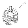
도 1은 본 발명의 일실시예에 따른 차량용 멀티 오퍼레이팅 스위치 유니트의 개략적인 사시도이다.
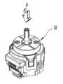
도 2는 본 발명의 일실시예에 따른 차량용 멀티 오퍼레이팅 스위치 유니트의 개략적인 로터리 동작 작동 상태를 도시하는 사시도이다.
도 3은 본 발명의 일실시예에 따른 차량용 멀티 오퍼레이팅 스위치 유니트의 개략적인 디렉셔널 틸팅 동작 상태를 도시하는 사시도이다.
도 4는 본 발명의 일실시예에 따른 차량용 멀티 오퍼레이팅 스위치 유니트의 개략적인 푸시 동작 상태를 도시하는 사시도이다.
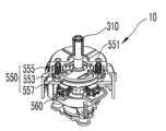
도 5는 본 발명의 일실시예에 따른 차량용 멀티 오퍼레이팅 스위치 유니트의 개략적인 분해 사시도이다.
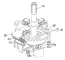
도 6은 본 발명의 일실시예에 따른 차량용 멀티 오퍼레이팅 스위치 유니트의 개략적인 부분 절단 사시도이다.
도 7은 본 발명의 일실시예에 따른 차량용 멀티 오퍼레이팅 스위치 유니트의 스위치 샤프트부의 개략적인 사시도이다.
도 8은 본 발명의 일실시예에 따른 차량용 멀티 오퍼레이팅 스위치 유니트의 로터리 엔코더의 개략적인 사시도이다.
도 9는 본 발명의 일실시예에 따른 차량용 멀티 오퍼레이팅 스위치 유니트의 개략적인 부분 절단 사시도이다.
도 10은 본 발명의 일실시예에 따른 차량용 멀티 오퍼레이팅 스위치 유니트의 디렉셔널 틸팅시 디렉셔널 리턴부의 작동 상태를 나타내는 개략적인 부분 절단 측면도이다.
도 11은 본 발명의 일실시예에 따른 차량용 멀티 오퍼레이팅 스위치 유니트의 디렉셔널 틸팅 동작시 작동 상태를 도시하는 개략적인 부분 사시도이다.
도 12는 본 발명의 일실시예에 따른 차량용 멀티 오퍼레이팅 스위치 유니트의 디렉셔널 스위치의 장착 상태를 나타내는 개략적인 사시도이다.
도 13은 본 발명의 일실시예에 따른 차량용 멀티 오퍼레이팅 스위치 유니트의 디렉셔널 틸팅 동작 상태를 나타내는 개략적인 부분 측면도이다.
도 14는 본 발명의 일실시예에 따른 차량용 멀티 오퍼레이팅 스위치 유니트의 개략적인 부분 절단 사시도이다.
도 15는 본 발명의 일실시예에 따른 차량용 멀티 오퍼레이팅 스위치 유니트의 푸시 스위치부의 개략적인 부분 사시도이다.
도 16은 본 발명의 일실시예에 따른 차량용 멀티 오퍼레이팅 스위치 유니트의 디렉셔널 바텀 슬라이드의 저면도이다.
도 17은 본 발명의 일실시예에 따른 차량용 멀티 오퍼레이팅 스위치 유니트의 디렉셔널 틸팅 동작 과정을 나타내는 상태도이다.
도 18 내 도 23은 본 발명의 다른 일실시예에 따른 차량용 멀티 오퍼레이팅 스위치 유니트의 구성에 대한 개략적인 부분 사시도, 부분 측단면도 및 상태도이다.
도 24는 본 발명의 또 다른 일실시예에 따른 차량용 멀티 오퍼레이팅 스위치 유니트의 개략적인 분해 사시도이다.
도 25 및 도 26은 본 발명의 또 다른 일실시예에 따른 차량용 멀티 오퍼레이팅 스위치 유니트의 디렉셔널 스위치에 대한 개략적인 사시도이다.
도 27은 본 발명의 또 다른 일실시예에 따른 차량용 멀티 오퍼레이팅 스위치 유니트의 디렉셔널 스위치에 대한 개략적인 측면도이다.
도 28은 본 발명의 다른 일실시예에 따른 단순한 반경 방향 가동되는 디렉셔널 스위치에 대한 개략적인 측면도이다.
도 29는 본 발명의 또 다른 일실시예에 따른 차량용 멀티 오퍼레이팅 스위치 유니트의 디렉셔널 스위치에 대한 개략적인 부분 측면도이다.
도 30은 본 발명의 또 다른 일실시예에 따른 차량용 멀티 오퍼레이팅 스위치 유니트의 개략적인 분해 사시도이다.
도 31 내지 도 33은 본 발명의 또 다른 일실시예에 따른 차량용 멀티 오퍼레이팅 스위치 유니트의 푸시 스위치부 및 로터리 스위치부의 개략적인 부분 사시도이다.
도 34 내지 도 37은 본 발명의 또 다른 일실시예에 따른 차량용 멀티 오퍼레이팅 스위치 유니트의 푸시 스위치부의 작동 상태도이다.
도 38 및 도 39는 본 발명의 또 다른 일실시예에 따른 차량용 멀티 오퍼레이팅 스위치 유니트의 로터리 디텐트부의 개략적인 변형 상태 사시도이다.
도 40 내지 도 42는 본 발명의 또 다른 일실시예에 따른 차량용 멀티 오퍼레이팅 스위치 유니트의 바텀 슬라이드 사이드와 접하여 안내하는 슬라이드 사이드 가이드의 배치도, 사시도 및 작동 위치 관계도이다.1 is a schematic perspective view of a multi-operating switch unit for a vehicle according to an embodiment of the present invention.
Figure 2 is a perspective view showing a schematic rotary operation operating state of a multi-operating switch unit for a vehicle according to an embodiment of the present invention.
Figure 3 is a perspective view showing a schematic directional tilting operation state of a multi-operating switch unit for a vehicle according to an embodiment of the present invention.
Figure 4 is a perspective view showing a schematic push operation state of a multi-operating switch unit for a vehicle according to an embodiment of the present invention.
Figure 5 is a schematic exploded perspective view of a multi-operating switch unit for a vehicle according to an embodiment of the present invention.
Figure 6 is a schematic partial cutaway perspective view of a multi-operating switch unit for a vehicle according to an embodiment of the present invention.
Figure 7 is a schematic perspective view of the switch shaft portion of a multi-operating switch unit for a vehicle according to an embodiment of the present invention.
Figure 8 is a schematic perspective view of a rotary encoder of a multi-operating switch unit for a vehicle according to an embodiment of the present invention.
Figure 9 is a schematic partially cut away perspective view of a multi-operating switch unit for a vehicle according to an embodiment of the present invention.
Figure 10 is a schematic partially cut side view showing the operating state of the directional return unit during directional tilting of the multi-operating switch unit for a vehicle according to an embodiment of the present invention.
Figure 11 is a schematic partial perspective view showing an operating state during a directional tilting operation of a multi-operating switch unit for a vehicle according to an embodiment of the present invention.
Figure 12 is a schematic perspective view showing the installation state of the directional switch of the multi-operating switch unit for a vehicle according to an embodiment of the present invention.
Figure 13 is a schematic partial side view showing a directional tilting operation state of a multi-operating switch unit for a vehicle according to an embodiment of the present invention.
Figure 14 is a schematic partial cutaway perspective view of a multi-operating switch unit for a vehicle according to an embodiment of the present invention.
Figure 15 is a schematic partial perspective view of the push switch portion of the multi-operating switch unit for a vehicle according to an embodiment of the present invention.
Figure 16 is a bottom view of the directional bottom slide of the multi-operating switch unit for a vehicle according to an embodiment of the present invention.
Figure 17 is a state diagram showing the directional tilting operation process of the multi-operating switch unit for a vehicle according to an embodiment of the present invention.
18 to 23 are schematic partial perspective views, partial side cross-sectional views, and state diagrams of the configuration of a multi-operating switch unit for a vehicle according to another embodiment of the present invention.
Figure 24 is a schematic exploded perspective view of a multi-operating switch unit for a vehicle according to another embodiment of the present invention.
25 and 26 are schematic perspective views of a directional switch of a multi-operating switch unit for a vehicle according to another embodiment of the present invention.
Figure 27 is a schematic side view of a directional switch of a multi-operating switch unit for a vehicle according to another embodiment of the present invention.
Figure 28 is a schematic side view of a simple radially operated directional switch according to another embodiment of the present invention.
Figure 29 is a schematic partial side view of the directional switch of a multi-operating switch unit for a vehicle according to another embodiment of the present invention.
Figure 30 is a schematic exploded perspective view of a multi-operating switch unit for a vehicle according to another embodiment of the present invention.
31 to 33 are schematic partial perspective views of the push switch unit and the rotary switch unit of a multi-operating switch unit for a vehicle according to another embodiment of the present invention.
Figures 34 to 37 are diagrams showing the operating state of the push switch unit of a multi-operating switch unit for a vehicle according to another embodiment of the present invention.
Figures 38 and 39 are schematic perspective views of a deformed state of the rotary detent portion of a multi-operating switch unit for a vehicle according to another embodiment of the present invention.
Figures 40 to 42 are a layout view, a perspective view, and an operating position relationship diagram of a slide side guide that guides in contact with the bottom slide side of a multi-operating switch unit for a vehicle according to another embodiment of the present invention.
이하, 본 발명의 바람직한 실시예를 첨부된 도면들을 참조하여 상세히 설명한다. 우선 각 도면의 구성요소들에 참조부호를 부가함에 있어서, 동일한 구성요소들에 대해서는 비록 다른 도면상에 표시되더라도 가능한 한 동일한 부호를 가지도록 하고 있음에 유의해야 한다. 또한, 본 발명을 설명함에 있어, 관련된 공지 구성 또는 기능에 대한 구체적인 설명이 본 발명의 요지를 흐릴 수 있다고 판단되는 경우에는 그 상세한 설명은 생략한다.Hereinafter, preferred embodiments of the present invention will be described in detail with reference to the attached drawings. First, when adding reference numerals to components in each drawing, it should be noted that identical components are given the same reference numerals as much as possible even if they are shown in different drawings. Additionally, in describing the present invention, if it is determined that a detailed description of a related known configuration or function may obscure the gist of the present invention, the detailed description will be omitted.
본 발명의 차량용 멀티 오퍼레이팅 스위치 유니트(10)는 하우징부(100)와 기판(200)과 스위치 샤프트부(300)와 로터리 스위치부(400)와 디렉셔널 스위치부(500)와 푸시 스위치부(600)를 포함한다. 본 발명의 차량용 멀티 오퍼레이팅 스위치 유니트(10)는 차량에 사용되는 스위치 유니트로서 다양한 조작 상태 구현을 가능하도록 하여 차량의 다양한 기능, 예를 들어 차량에 구비되는 오디오, 네비게이션, 공조 장치 등의 다양한 차량용 전장 장치 들의 작동 상태를 조정 제어하는데 사용될 수 있다.The
하우징부(100)는 하우징 커버(110)와 하우징 베이스(130)를 구비하는데, 하우징 커버(110)와 하우징 베이스(130)는 서로 체결되어 내부 공간을 형성한다. 하우징 베이스(130)는 기판(200)을 지지하는 구조를 형성하고, 하우징 커버(110)는 하우징 베이스(130)와 맞물리어 체결되어 내부 공간을 형성한다. 하우징 커버(110)의 일면에는 하우징 커버 관통구(111)가 형성되고, 하우징 커버 관통구(111)에는 하기되는 스위치 샤프트부(300)의 일단이 외부로 노출되어 운전자 등의 사용자의 조작력 제공을 가능하게 한다.The
본 실시예의 하우징부(100)는 하우징 홀더(120)를 더 구비하는데, 하우징 홀더(120)는 하우징 커버(110)와 하우징 베이스(130) 사이에 배치되고, 하우징 홀더(120)는 하우징 베이스(130)와 함께 기판(200)을 지지할 수 있고, 하우징 홀더(120)는 하우징 커버(110)와 하우징 베이스(130)가 이루는 공간을 분리하여 하기되는 로터리 스위치부(400)와 디렉셔널 스위치부(500)의 작동시 간섭 발생을 방지하는 공간 분할 기능을 수행할 수 있다.The
기판(200)은 하우징부(100)의 내부에 배치되는데, 기판(200)에는 다양한 전기 소자가 배치될 수 있고 이들 전기 소자는 기판(200)에 형성되는 배선을 통하여 연결될 수도 있고 다른 요소, 예를 들어 플렉서블기판 내지 케이블과 같은 요소들을 통하여 전기적 소통을 이루는 구조를 취할 수도 있다. 기판(200)은 본 실시예에서 양면 기판으로 구현되어 양면에 각종 소자들이 배치될 수 있다.The
기판(200)의 중앙에는 기판 관통구(202)가 형성되어 스위치 샤프트부(300)의 관통 배치를 가능하게 한다. 기판(200)의 일단에는 기판 커넥터(201)가 형성되는데, 기판 커넥터(201)에는 커넥터(203)가 연결되고 커넥터(203)를 통하여 외부 전기 장치, 예를 들어 제어부(미도시)와 같은 외부 전기 장치와의 연결이 이루어질 수 있다.A substrate through-
스위치 샤프트부(300)는 일단이 하우징부(100)에 수용되고 타단이 외부로 노출되는 구조를 취하는데, 스위치 샤프트부(300)는 스위치 샤프트 바디(310)와 스위치 샤프트 힌지(320)를 포함한다. 스위치 샤프트 바디(310)는 사전 설정된 소정의 길이를 갖는 로드 타입으로 구현되고 스위치 샤프트 힌지(320)는 스위치 샤프트 바디(310)의 단부에 배치되어 하우징부(100)의 내부에 수용 배치된다. 본 실시예에서 도시되지는 않았으나 스위치 샤프트 바디(310)의 외부로 노출된 단부에는 스위치 노브(미도시)가 장착되어 운전자 등의 그립을 원활하게 하여 소정의 조작감을 제공할 수 있다.The
스위치 샤프트 바디(310)의 하단에 연결되는 스위치 샤프트 힌지(320)는 본 실시예에서 구형 형상을 취하는데 구체적 설계 사양에 따라 변형된 형상을 구비할 수 있다. 스위치 샤프트 힌지(320)는 스위치 샤프트부(300)의 회동 중심을 이루는데, 스위치 샤프트 힌지(320)는 하우징 홀더(120)와 하기되는 로터리 스위치부(400)의 로터리 엔코더(410)에 형성되는 로터리 엔코더 수용부(411, 도 5 참조)에 의하여 형성되는 공간에 배치되고, 하우징 홀더(120)에 형성되는 하우징 홀더 관통구(121)를 통하여 스위치 샤프트 바디(310)가 관통 배치되는 구조를 형성한다.The
따라서, 사용자에 의하여 스위치 샤프트 바디(310)는 축방향 회전 운동, 수평 가압력을 통한 스위치 샤프트 바디(310)의 스위치 샤프트 힌지(320)를 중심으로 하는 틸팅 운동, 및 스위치 샤프트 바디(310)를 하방향으로 압입하는 압입 푸시 운동 등의 복합적인 운동을 이룰 수 있다.Accordingly, by the user, the
본 실시예에 따른 스위치 샤프트 바디(310)의 디렉셔널 틸팅 운동의 회동 중심점으로의 기능을 수행하는 스위치 샤프트 힌지(320)의 위치는 하우징부와 기판의 사이, 보다 구체적으로 기판(200)과 하우징 베이스(130)의 사이, 더욱 구체적으로, 기판(200)의 하부에 배치되는 하우징 홀더(120)와 하우징 베이스(130)의 사이에 배치되고, 디렉셔널 스위치부(500)는 기판(200)과 하우징 커버(110) 사이에 배치되는 구조를 취하여 스위치 샤프트 바디(310)의 회동 중심인 스위치 샤프트 힌지(320)로부터 이격되어 상부에 배치되는 디렉셔널 스위치부(500)의 디렉셔널 스위치(560)의 가동을 위하여 요구되는 스위치 샤프트 바디(310)의 디렉셔널 틸팅 운동을 최소화시켜 하우징 커버 등과의 이격 거리를 최소화시켜 하우징 커버 등을 통한 내부로의 이물 유입을 방지할 수 있다.The position of the
즉, 도 17에는 디렉셔널 틸팅 동작을 구현하는 스위치 샤프트 바디 및 스위치 샤프트 힌지(320)의 동작 상태도가 도시되는데, 스위치 샤프트 바디의 단부에는 노브(109)가 배치된다. 정상 상태에서 스위치 샤프트 바디는 선 O-A 상에 배치되고, 본 발명의 스위치 샤프트 바디의 디렉셔널 틸팅 동작으로 디렉셔널 스위치(560)를 가동시키기 위한 위치를 선 I-I 상의 P라 할 때 스위치 샤프트 바디(310)가 위치 P에 도달할 때의 스위치 샤프트 바디(310)의 길이는 선 O-B 상에 배치되며 이때 노브(109)의 단부는 도면 부호 Q로 지시된 위치를 점유한다.That is, FIG. 17 shows an operation state diagram of the switch shaft body and the
반면, 본 발명의 구조와 달리 스위치 샤프트 힌지가 가상의 중심점(Ovrt)를 점유하는 경우 디렉셔널 스위치를 가동시키기 위하여 요구되는 위치 P까지 스위치 샤프트가 이동할 때의 스위치 샤프트는 선 Ovrt-C 상에 배치되고, 이 때 노브(109)의 단부는 Qvrt의 위치를 점하게 된다. 선 II-II를 소정의 기준선이라 할 때 선 II-II로부터 각각의 경우에 대한 노브(109)의 단부(Q,Qvrt)의 거리는 L1, L2로 표시되고, L1>L2(L1-L2=L3>0)의 관계를 이루게 된다.On the other hand, unlike the structure of the present invention, when the switch shaft hinge occupies the virtual center point (Ovrt), the switch shaft is placed on the line Ovrt-C when the switch shaft moves to the position P required to operate the directional switch. And at this time, the end of the
즉, 스위치 샤프트 힌지의 하부 배치 구조를 통하여 디렉셔널 스위치(560)를 가동시키기 위하여 요구되는 디렉셔널 틸팅 각도를 최소화시킴으로써 노브(109)의 하우징부를 향한 이동 거리를 최소화시키고 이로부터 노브(109)와 하우징부의 하우징 커버와의 이격 거리를 최소화시킴으로써 하우징 커버 측을 통한 이물 유입 가능성을 저감시키고, 컴팩트한 구성을 가능하게 할 수 있다.That is, by minimizing the directional tilting angle required to operate the
로터리 스위치부(400)는 스위치 샤프트부(300)의 축회동을 감지하고 이를 신호로 제어부(미도시)와 같은 외부 장치로 출력 전달한다. 로터리 스위치부(400)는 로터리 엔코더(410)와 로터리 스위치 센서(420)를 포함하는데, 로터리 엔코더(410)는 기판(20))과 하우징부(100)의 하우징 베이스(130) 사이에 배치되고 스위치 샤프트부(300)의 스위치 샤프트 힌지(320)의 적어도 일부를 수용 가능한 구조를 취한다. 즉, 로터리 엔코더(410)는 로터리 엔코더 수용부(411)가 포함되는데, 로터리 엔코더 수용부(411)는 로터리 엔코더(410)의 중앙에 형성되는 공간으로 로터리 엔코더(410)의 상부에 배치되는 하우징 홀더(120)와 함께 장착 공간을 형성하여 스위치 샤프트 힌지(320)의 안착을 가능하게 한다.The rotary switch unit 400 detects the shaft rotation of the
로터리 엔코더(410)의 내측으로 로터리 엔코더 수용부(411)를 구획하는 내측부에 로터리 엔코더 수용 가이드(413)가 형성되고, 스위치 샤프트부(300)의 스위치 샤프트 힌지(320)의 외주에 샤프트 힌지 가이드(321)가 형성되는데, 샤프트 힌지 가이드(321)는 로터리 엔코더 수용 가이드(413)에 수용 배치된다.A rotary
로터리 엔코더 수용 가이드(413)와 샤프트 힌지 가이드(321)는 상대적인 축방향 회동을 방지하도록 맞물리는 구조를 취하는데, 본 실시예에서 로터리 엔도커 수용 가이드(413)와 샤프트 힌지 가이드(321)의 축방향, 측 스위치 샤프트 바디(310)의 축길이 방향을 따른 소정의 상대 가동은 허용되는 구조를 취한다. 즉, 로터리 엔코더 수용 가이드(413)는 스위치 샤프트 바디(310)에 외력이 인가되지 않은 상태에서의 축길이 방향으로 장방형 구조를 취하여 로터리 엔코더 수용 가이드(413)의 로터리 엔코더(410)의 원주 방향에 대한 길이보다 로터리 엔코더(410)의 회전축의 축길이 방향에 대한 길이가 큰 값을 갖는 구조를 취하는데, 로터리 엔코더 수용 가이드(413)의 로터리 엔코더(410)의 원주 방향에 대한 길이를 횡방향 길이 A, 로터리 엔코더(410)의 회전축의 축길이 방향에 대한 길이를 종방향 길이 B라 할 때, 종횡비(AR=B/A)는 1보다 큰 값을 갖도록 구성된다.The rotary
로터리 엔코더(410)의 외주에는 복수 개의 로터리 엔코더 슬릿(415)가 형성되는데, 로터리 엔코더 슬릿(415)의 대응되는 위치에는 로터리 스위치 센서(420)가 배치된다. 즉, 로터리 스위치 센서(420)는 본 실시예에서 광센서로 형성되고, 로터리 스위치 센서(420)는 기판(200)의 하면에 배치된다. 로터리 스위치 센서(420)의 대응되는 위치에 로터리 엔코더(410)의 단부, 즉 로터리 엔코더 슬릿(415)이 가동 가능하게 배치되어, 스위치 샤프트부(300)와 함께 축방향 회동을 이루는 로터리 엔코더(410)의 회전 상태를 로터리 엔코더 슬릿(415)의 이동 회수를 통하여 로터리 스위치 센서(420)가 감지하고 이를 기판(200)을 거쳐 외부 장치로 전달할 수 있다.A plurality of rotary encoder slits 415 are formed on the outer periphery of the
로터리 스위치부(400)의 원치 않는 회동 상태를 방지하고 보다 정확한 회전 신호를 생성함으로써 스위치 샤프트부의 회전 동작을 통한 차량의 장치들의 작동 상태 설정에 있어 오작동을 방지하기 위하여, 스위치 샤프트부(300) 및 로터리 엔코더(410)의 회전 동작을 디텐팅시키는 구성요소를 더 구비할 수 있다. 즉, 본 발명의 로터리 스위치부(400)는 로터리 디텐트부(430)를 포함하는데, 로터리 디텐트부(430)는 로터리 디텐트(431)와 로터리 디텐트 볼(433)과 로터리 디텐트 탄성부(435)를 포함하고, 하우징부(100)의 하우징 베이스(130)에는 베이스 로터리 디텐트 수용부(131)가 구비된다. 베이스 로터리 디텐트 수용부(131)에는 로터리 디텐트 탄성부(435)가 수용 배치된다.In order to prevent malfunctions in setting the operating state of the vehicle devices through the rotation of the switch shaft portion by preventing unwanted rotation of the rotary switch portion 400 and generating a more accurate rotation signal, the
로터리 디텐트(431)는 로터리 엔코더(410)의 저면에 형성되는데, 별도의 구성으로 형성된 후 로터리 엔코더(410)의 저면에 장착될 수도 있으나, 본 실시예에서의 로터리 디텐트(431)는 로터리 엔코더(410)의 저면에 일체로 형성되는 구조를 취한다. 로터리 디텐트(431)는 하나 이상의, 본 실시예에서는 복수 개의 돌기 및 요홈 형상으로 구현되고 소정의 사전 설정된 간격으로 배치되는 구조를 취할 수 있다. 본 실시예에서 도시되는 않았으나 경우에 따라 로터리 엔코더의 과도한 회동을 방지하기 위한 로터리 스톱퍼(미도시)가 더 구비되어 회전 제한 영역을 형성하는 구조를 취할 수도 있고, 회동 제한없이 무한회전을 이루되, 전원 오프시 로터리 스위치 센서의 회동 기준을 초기화시키는 구조를 취할 수도 있는 등 다양한 구성이 가능하다.The
로터리 디텐트(431)의 대응되는 위치에 베이스 로터리 디텐트 수용부(131)가 형성되고, 베이스 로터리 디텐트 수용부(131)에는 코일 스프링 구조의 로터리 디텐트 탄성부(435)가 배치된다. 로터리 디텐트 탄성부(435)는 볼 형상의 로터리 디텐트 볼(433)을 탄성 지지하는데, 로터리 디텐트 볼(433)은 로터리 디텐트(431)와 상시 접촉 상태를 형성한다. 본 실시예에서 로터리 디텐트 탄성부는 코일 스프링으로 구현되었으나, 로터리 디텐트 탄성부는 스파이럴 타입의 판 스프링으로 구현되고 펀칭 돌출된 부분이 로터리 디텐트와 접촉하여 디텐팅 동작을 이루는 등 로터리 디텐팅 동작을 구현하는 범위에서 다양한 구성이 가능하다.A base rotary
한편, 본 발명의 디렉셔널 스위치부(500)는 스위치 샤프트부(300)의 디렉셔널 동작, 즉, 스위치 샤프트부(300)의 스위치 샤프트 바디(310)를 스위치 샤프트 힌지(320)를 중심으로 측면 이동시키는 힘을 인가하는 경우 스위치 샤프트부(300)의 틸팅 동작으로 인하여 발생하는 기판(200)의 평행한 평면 상에서 볼 때 평면 상에서의 일방향으로의 운동 동작을 감지하여 이를 출력한다.Meanwhile, the
디렉셔널 스위치부(500)는 디렉셔널 슬라이드부(510)와 디렉셔널 스위치(560)와 디렉셔널 리턴부(550)를 포함한다. 디렉셔널 슬라이드부(510)는 스위치 샤프트부(300)의 틸팅 디렉셔널 동작에 의하여 하우징부(100) 내에서 위치 가변 가능한데, 디렉셔널 슬라이드부(510)는 기판(200)과 평행한 평면 상에서 가동 운동을 이루어, 스위치 샤프트부의 틸팅 운동이 기판에 평행한 평면 상에서 평면 운동으로 전환되는 디렉셔널 스위치부(500)의 디렉셔널 틸팅 운동이 이루어질 수 있다.The
디렉셔널 스위치(560)는 기판(200)에 배치되고 디렉셔널 슬라이드부(510)의 위치 가변에 의하여 가동되어 변화된 신호를 생성하는데, 본 실시예에서 디렉셔널 스위치(560)는 접촉 스위치로 구현되나 설계 사양에 따라 다양한 변형이 가능하다.The
디렉셔널 스위치(560)는 기판(200)의 일면으로 기판(200)의 하우징 커버(110)를 향한 상면에 배치되는데, 하우징 홀더(120)를 통하여 구획 분할되는 상부 영역에 배치되어 가동될 수 있는 구조를 형성한다.The
한편, 본 발명에 따른 디렉셔널 슬라이드부(510)는 디렉셔널 탑 슬라이드(520)와 디렉셔널 미디엄 슬라이드(530)와 디렉셔널 바텀 슬라이드(540)를 포함하는데, 디렉셔널 미디엄 슬라이드(530)는 하우징 베이스(130)와 하우징 커버(110) 사이, 보다 구체적으로는 하우징 커버(110)와 하우징 홀더(120) 사이에 배치되는데, 디렉셔널 미디엄 슬라이드(530)의 중앙에는 미디엄 관통구(533)가 구비되어 스위치 샤프트부(300)의 스위치 샤프트 바디(310)의 관통을 허용한다.Meanwhile, the
또한, 디렉셔널 미디엄 슬라이드(530)의 측면에는 미디엄 사이드(535)가 형성되는데, 미디엄 사이드(535)는 디렉셔널 미디엄 슬라이드(530)의 측면에 제거된 홈을 형성하여 하기되는 디렉셔널 리턴부의 구성요소와의 간섭을 배제할 수 있다.In addition, a
디렉셔널 미디엄 슬라이드(530)는 소정의 플레이트 구조를 형성하고, 디렉션러 미디엄 슬라이드(530)는 미디엄 어퍼 가이드(531)와 미디엄 로워 가이드(537)를 구비하는데, 미디엄 어퍼 가이드(531)는 디렉셔널 미디엄 슬라이드(530)의 일면, 즉 하우징 커버(110)를 향한 일면에 형성되고, 미디엄 로워 가이드(537)는 디렉셔널 미디엄 슬라이드(530)의 아랫면, 즉 하우징 홀더(120)를 향한 일면에 형성된다. 디렉셔널 탑 슬라이드(520, 도 13 점선 참조)는 하우징 커버(110)의 일면으로 디렉셔널 미디엄 슬라이드(530)를 향한 저면에 형성되고 디렉셔널 미디엄 슬라이드(530)와 상대 가동 가능하게 맞물림되는데, 디렉셔널 탑 슬라이드(520)는 디렉셔널 미디엄 슬라이드(530)의 미디엄 어퍼 가이드(531)와 맞물리어 상대 운동 가능한 구조를 형성하여 하우징부(100)의 내부에서 디렉셔널 미디엄 슬라이드(530)가 미디엄 어퍼 가이드(531) 및 디렉셔널 탑 슬라이드(520)의 길이 방향으로 수평면 상에서의 가동을 이루는 것을 가능하게 한다.The directional
본 실시예에서 디렉셔널 탑 슬라이드(520)는 요홈 형상으로 그리고 미디엄 어퍼 가이드(531)가 돌기 형상으로 구성되는데, 양자는 서로 반대되는 구성을 취할 수도 있는 등 다양한 변형이 가능하다.In this embodiment, the directional
또한, 디렉셔널 미디엄 슬라이드(530)의 타면, 즉 저면에는 미디엄 로워 가이드(537)가 형성되는데, 미디엄 로워 가이드(537)는 하기되는 디렉셔널 바텀 슬라이드(540)의 일면 상에 형성되는 바텀 가이드(541)와 상대 가동 가능하게 맞물림되는 구조를 형성한다. 본 실시예에서 미디엄 로워 가이드(537)는 돌기 구조로 그리고 바텀 가이드(541)는 요홈 구조로 형성되는데, 반대되는 구조를 형성할 수도 있다.In addition, a medium
디렉셔널 바텀 슬라이드(540)는 바텀 슬라이드 바디(544)와 바텀 슬라이드 사이드(547)와 바텀 슬라이드 가동부(545)를 포함하는데, 바텀 슬라이드 바디(544)는 일면 상에 상기 기술된 바텀 가이드(541)가 형성되고, 중앙에 바텀 관통구(542)가 형성된다. 바텀 관통구(542)는 상기 미디엄 관통구(533)와 동심 구조를 이루나, 바텀 관통구(542)의 내경은 미디엄 관통구(533)의 내경보다 작은 값을 구비하는데, 바텀 관통구(542)의 내경은 스위치 샤프트부(300)의 스위치 샤프트 바디(310)의 직경에 근사한 값을 구비하여 바텀 관통구(542)의 내측면은 스위치 샤프트 바디(310)의 외주면과 접촉하여 스위치 샤프트부(300)의 틸팅 운동시 디렉셔널 바텀 슬라이드(540)가 함께 수평면 상에서 이동하는 디렉셔널 틸팅 운동을 이룰 수 있다.The directional
바텀 슬라이드 바디(544)의 일면 상에는 바텀 슬라이드 돌기(543)가 형성되어 상면에 배치되는 디렉셔널 미디엄 슬라이드(530)와의 접촉면을 최소화시키는 점접촉 구조를 형성하여 접촉 저항을 줄이는 구조를 더 구비할 수도 있다. 본 실시예에서는 바텀 슬라이드 바디 측에 돌기 구조가 형성되는 구조를 취하였으나 디렉셔널 미디엄 슬라이드 측에 배치되는 구조를 취할 수도 있는 등 변형이 가능하다.A
바텀 슬라이드 사이드(547)는 바텀 슬라이드 바디(544)의 측면으로 연장 형성되는 구조를 이루는데, 경우에 따라서는 별개물로 형성되어 바텀 슬라이드 바디와 체결되는 구조를 취할 수도 있다. 바텀 슬라이드 사이드(547)는 미디엄 사이드(535)의 대응되는 위치에 형성되는데, 바텀 슬라이드 사이드(547)에는 하기되는 리턴 그루브(557)가 형성된다.The
바텀 슬라이드 가동부(545)는 바텀 슬라이드 바디(544)의 하부에 형성되고, 디렉셔널 바텀 슬라이드(540)가 디렉셔널 틸팅 운동을 이루는 경우 바텀 슬라이드 가동부(545)는 기판 상으로 바텀 관통구(542)의 인근 외측 등반경 상으로 등간격 배치되는 디렉셔널 스위치(560)를 가동시킬 수 있다. 본 실시예에서 디렉셔널 스위치(560)는 접촉 스위치로 구현되는데, 바텀 슬라이드 가동부(540)는 디렉셔널 스위치(560)와의 접촉을 가능하게 하는 돌출 구조를 형성한다. 본 실시예에서 디렉셔널 스위치(560)는 4개가 구비되고 바텀 슬라이드 가동부(545)도 이에 대응하여 4개의 가동면을 갖는 사각형 돌출물 구조를 형성하는데, 각각의 할당된 가동면이 디렉셔널 스위치(560)와 접촉을 이루어 디렉셔널 스위치(560)의 변화된 신호 출력을 생성한다. 보다 자세하게는 도 16에 도시된 바와 같이, 바텀 슬라이드 가동부(545)는 디렉셔널 바텀 슬라이드(540)의 저면에 배치되는데, 바텀 슬라이드 가동부(545)는 사각형 돌출물 구조로 형성되나, 접촉시 원활한 가동을 이루고 디렉셔널 동작시 안정적인 접촉 및 분리 동작을 통하여 디렉셔널 스위치의 내구성 저하를 방지할 수 있도록 소정의 내곡된 원호 형상을 갖는 구조로 형성될 수도 있다.The bottom slide
한편, 본 실시예에서 디렉셔널 스위치는 스위치 샤프트의 중심으로부터 반경 방향으로 가압되는 수평 이동 방식의 디렉셔널 스위치에 대하여 기술되었으나, 본 발명의 차량용 멀티 오퍼레이팅 스위치 유니트의 디렉셔널 스위치는 반경 방향으로의 가압 동작에 국한되는 것은 아니다. 즉, 디렉셔널 바텀 슬라이더는 반경 반향으로의 수평 이동 동작을 이루나, 본 발명의 디렉셔널 스위치도 반드시 수평 이동 동작을 이루는 구성에 한정되는 것은 아니다.Meanwhile, in this embodiment, the directional switch has been described as a horizontally moving directional switch that is pressed in the radial direction from the center of the switch shaft, but the directional switch of the multi-operating switch unit for a vehicle of the present invention is pressed in the radial direction. It is not limited to movement. In other words, the directional bottom slider performs a horizontal movement in a radial direction, but the directional switch of the present invention is not necessarily limited to a configuration that performs a horizontal movement.
도 24 내지 도 27에는 본 발명의 디렉셔널 스위치의 다른 일예가 도시된다. 발명의 이해를 용이하게 하기 위하여 도면 부호와 명칭을 동일하게 유지한다. 디렉셔널 스위치(560)는 디렉셔널 스위치 하우징(561)과 디렉셔널 스위치 노브(563)를 포함하고, 디렉셔널 스위치 하우징(561)의 내부에 배치되는 디렉셔널 스위치 접점(565,567)은 디렉셔널 스위치 노브(563)를 통하여 가동된다.24 to 27 show another example of the directional switch of the present invention. To facilitate understanding of the invention, drawing symbols and names are kept the same. The
디렉셔널 스위치 하우징(561)은 기판(200)의 일면 상에 배치되는데, 스위치 샤프(300)를 중심으로 등반경 등간격 배치 구조를 취하는 것이 바람직하다.The directional switch housing 561 is disposed on one side of the
디렉셔널 스위치 하우징(561)은 디렉셔널 스위치 하우징 커버(5611)와 디렉셔널 스위치 하우징 바디(5613)를 포함하는데, 디렉셔널 스위치 하우징 커버(5611)와 디렉셔널 스위치 하우징 바디(5613)는 서로 맞물리어 내부 공간을 형성하고 내부 공간에 디렉셔널 스위치 노브(563) 등의 적어도 일부가 수용 배치되는 구조를 취한다.The directional switch housing 561 includes a directional switch housing cover 5611 and a directional switch housing body 5613. The directional switch housing cover 5611 and the directional switch housing body 5613 are engaged with each other. It has a structure in which an internal space is formed and at least a part of the directional switch knob 563, etc., is accommodated and arranged in the internal space.
본 실시예에서 디렉셔널 스위치 하우징(561)은 디렉셔널 스위치 하우징 커버(5611)와 디렉셔널 스위치 하우징 바디(5613)를 포함하는 구조를 취하였으나, 경우에 따라 디렉셔널 스위치 하우징 커버만 기판의 일면 상에 고정 장착 가능한 구조를 취하거나, 디렉셔널 스위치 하우징 바디와 기판이 일체화되어 사출 형성되는 구조를 취할 수도 있는 등 설계 사양에 따라 다양한 구성이 가능하다.In this embodiment, the directional switch housing 561 has a structure including a directional switch housing cover 5611 and a directional switch housing body 5613, but in some cases, only the directional switch housing cover is on one side of the substrate. A variety of configurations are possible depending on the design specifications, such as a structure that can be fixedly mounted, or a structure in which the directional switch housing body and the substrate are integrated and formed by injection.
디렉셔널 스위치 하우징(561)의 일면으로 기판(200)이 향하는 일면의 방향과 동일한 방향으로 디렉셔널 스위치 하우징 노브 관통구(5612)이 배치된다.A directional switch housing knob through hole 5612 is disposed on one side of the directional switch housing 561 in the same direction as the side toward which the
디렉셔널 스위치 노브(563)은 적어도 일부가 디렉셔널 스위치 하우징의 일면 상에 노출 가능하록 디렉셔널 스위치 하우징(561)에 배치된다. 디렉셔널 스위치 노브(563)의 노출된 부위는 디렉셔널 슬라이드부와 접촉 가능한 구조를 취한다. 디렉셔널 스위치 노브(563)는 디렉셔널 스위치 하우징(561)의 내부 일지점을 중심으로 기판(200)에 평행한 축을 중심으로 회동 가능한 구조를 취한다.The directional switch knob 563 is disposed on the directional switch housing 561 so that at least a portion of it can be exposed on one surface of the directional switch housing. The exposed portion of the directional switch knob 563 has a structure that allows contact with the directional slide portion. The directional switch knob 563 has a structure that can be rotated around an axis parallel to the
도 27에 도시된 바와 같이, 디렉셔널 스위치 노브(563)는 외력이 가해지지 않는 정상 상태의 경우 디렉셔널 스위치 하우징 노브 관통구(5612)의 일면 상으로 노출되어 배치된다. 디렉셔널 슬라이드부의 디렉셔널 바텀 슬라이드(540)의 바텀 슬라이드 가동부(545)가 기판과 평행한 평면 상에서 수평 이동하는 경우 디렉셔널 스위치 노브(563)는 디렉셔널 스위치 하우징(561)의 내부 일지점을 중심으로 회동하여 디렉셔널 스위치 하우징(561)의 내측으로 진입한다.As shown in FIG. 27, the directional switch knob 563 is exposed and disposed on one surface of the directional switch housing knob through-hole 5612 in a normal state in which no external force is applied. When the bottom slide
디렉셔널 스위치 노브(563)가 회동하는 일지점, 즉 디렉셔널 스위치 노브(563)의 회동점은 스위치 샤프트(300)의 중심을 향한 단부 측에 배치된다. 보다 구체적으로,The point at which the directional switch knob 563 rotates, that is, the pivot point of the directional switch knob 563, is disposed on the end side toward the center of the
디렉셔널 스위치 노브(563)는 스위치 샤프트(300)의 중심으로부터 반경 방향으로 배치된다. 즉, 디렉셔널 스위치 노브(563)는 스위치 샤프트(300)의 중심에서 반경 방향으로 길이 방향을 갖도로 배치되는데, 디렉셔널 스위치 노브(563)는 기판(200)에 수직하게 배치되고 기판(300)에 수평하게 배치되는 회동축을 중심으로 회동하는 구조를 취하는데, 디렉셔널 스위치 노브(563)의 회동 중심은 디렉셔널 스위치 노브(563)의 길이 방향 중 반경 상 먼 측이 아닌 스위치 샤프트의 중심을 향한 단부 측에 배치된다. 즉, 도 27에 도시된 바와 같이, 디렉셔널 스위치 노브(563)는 도면 부호 CO이 아닌 도면 부호 CI를 중심으로 회동 가능하게 배치되는 구조를 취한다. 이러한 반경상 내측 지점을 회동 중심으로 함으로써, 디렉셔널 슬라이드부의 바텀 슬라이드 가동부의 이동에 대하여 디렉셔널 스위치 노브의 점짐적 회동을 가능하게 함으로써 디렉셔널 스위치 자체의 설계 자유도를 향상시킬 수도 있다.The directional switch knob 563 is disposed in a radial direction from the center of the
또한, 디렉셔널 스위치 노브(563)에 인가되는 외력 제거시 원위치 복귀하기 위한 디렉셔널 스위치 탄성부(564)와 디렉셔널 스위치 접점부(565,567)이 구비되는데, 디렉셔널 스위치 탄성부(564) 및 디렉셔널 스위치 접점부(565,567)는 디렉셔널 스위치 하우징의 내부에 배치될 수 있다.In addition, a directional switch elastic portion 564 and a directional switch contact portion 565 and 567 are provided to return to the original position when the external force applied to the directional switch knob 563 is removed. The directional switch elastic portion 564 and the direct switch contact portion 565 and 567 are provided. The directional switch contact portions 565 and 567 may be disposed inside the directional switch housing.
도 29에는 본 발명의 디렉셔널 스위치 탄성부 및 디렉셔널 스위치 접점부에 대한 일예가 도시된다. 즉, 디렉셔널 스위치 탄성부(564)는 디렉셔널 스위치 하우징(561)의 내부로 디렉셔널 스위치 노브(563)에 탄성 복귀력을 제공하는데, 디렉셔널 스위치 탄성부(564)는 디렉셔널 스위치 노브(563)의 회동 중심(CI)에 직접 연결되는 구조를 취할 수도 있다. 즉, 본 실시예에서 디렉셔널 스위치 탄성부(564)는 토션 스프링으로 구현되어 디렉셔널 스위치 노브(563)의 초기 탄성력으로 지지하고 외력 제거시 복원력에 의하여 디렉셔널 스위치 노브(563)를 원위치 복귀시키는 구조를 취한다.Figure 29 shows an example of the directional switch elastic portion and the directional switch contact portion of the present invention. That is, the directional switch elastic portion 564 provides an elastic return force to the directional switch knob 563 inside the directional switch housing 561, and the directional switch elastic portion 564 provides an elastic return force to the directional switch knob 563 ( 563) may have a structure that is directly connected to the center of rotation (CI). That is, in this embodiment, the directional switch elastic portion 564 is implemented as a torsion spring to support the initial elastic force of the directional switch knob 563 and to return the directional switch knob 563 to its original position by a restoring force when the external force is removed. Take structure.
디렉셔널 스위치 접점부(565,567)는 디렉셔널 스위치 가동 접점(565)와 디렉셔널 스위치 고정 접점(567)를 포함하는데,The directional switch contact portions 565 and 567 include a directional switch movable contact 565 and a directional switch fixed contact 567.
디렉셔널 스위치 가동 접점(565)은 디렉셔널 스위치 노브(563)에 의하여 가동되는데, 디렉셔널 스위치 가동 접점(565)은 디렉셔널 스위치 노브(563)의 저면에 배치되는 구조를 취할 수 있다.The directional switch movable contact point 565 is operated by the directional switch knob 563. The directional switch movable contact point 565 may have a structure disposed on the bottom of the directional switch knob 563.
디렉셔널 스위치 고정 접점(567)는 디렉셔널 스위치 노브(563)에 의하여 디렉셔널 스위치 가동 접점(565)이 가동되는 경우 접속 가능하게 대응 배치되는데, 디렉셔널 스위치 고정 접점(567)은 디렉셔널 스위치 하우징 바디(5613)에 형성되고 모듈화된 디렉셔널 스위치의 커넥터(미도시)를 통하여 기판(200)을 거쳐 외부 전기 장치 등과 전기적 소통을 이루는 구조를 취할 수 있다. 또한, 경우에 따라 앞서 기술된 바와 같이, 디렉셔널 스위치 하우징 바디와 기판이 일체화되어 인서트 사출되는 경우 기판에 디렉셔널 스위치 고정 접점도 기판에 일체 형성될 수도 있다.The directional switch fixed contact point 567 is arranged to be accessible when the directional switch movable contact point 565 is operated by the directional switch knob 563. The directional switch fixed contact point 567 is connected to the directional switch housing. A structure may be adopted to achieve electrical communication with an external electric device, etc. through the
이와 같이 디렉셔널 스위치 노브(563)는 기판에 평행한 일면 상에 노출 배치되고 회동 방식을 통하여 가동되는 구조를 취하여, 단순한 반경 방향으로의 가동에 의하여 요구되는 스트로크 공간(dc, 도 27 및 도 28 참조)에 대비하여 가동 공간을 상당히 축소함으로써 보다 컴팩트한 장치 구성이 가능하다.In this way, the directional switch knob 563 is exposed on one side parallel to the substrate and has a structure that moves through a rotation method, so that the stroke space (dc, Figures 27 and 28) required by simple radial movement By significantly reducing the operating space compared to (reference), a more compact device configuration is possible.
상기 디렉셔널 슬라이드부(510)의 디렉셔널 틸팅 운동, 즉 스위치 샤프트의 틸팅 운동에 의한 수평면 상에서의 수평 슬라이딩 운동인 디렉셔널 틸팅 운동은 디렉셔널 톱 슬라이드, 디렉셔널 미디엄 슬라이드 및 디렉셔널 바텀 슬라이드의 상대 운동을 통하여 이루어질 수 있는데, 디렉셔널 탑 슬라이드와 미디엄 어퍼 가이드 간의 상대 운동, 미디엄 로워 가이드와 바텀 가이드 간의 상대 운동을 통하여 이룰 수 있다. 본 실시예에서 미디엄 어퍼 가이드와 미디엄 로워 가이드는 동일 평면 상에 투영되는 경우 각각의 길이가 이루는 방향이 90도 교차 배치되는 구조를 취하여, 실질적으로 디렉셔널 틸팅 운동의 수평면 상에서의 어느 위치로의 운동도 가능하게 할 수 있다.The directional tilting movement of the
한편, 상기 기술된 바와 같이 디렉셔널 스위치부(500)는 디렉셔널 리턴부(550)를 포함하는데, 디렉셔널 리턴부(550)는 스위치 샤프트부에 인가되는 외력 제거후 디렉셔널 슬라이드부(510) 및 스위치 샤프트부(300)를 평면 상에서 원위치 복귀시킨다. 디렉셔널 리턴부(550)는 리턴 탄성부(553)와 리턴 플런저(555)와 리턴 그루브(557)를 포함하는데, 리턴 플런저(555)는 하우징부(100)에 가동 가능하게 수용된다. 즉, 하우징부(100)의 하우징 커버(110)에는 리턴 장착부(551)가 형성되는데, 리턴 장착부(551)에 리턴 플런저(555)가 가동 가능하게 수용 배치된다. 리턴 플런저(555)는 로드 타입으로 형성되고, 리턴 플런저(555)의 단부는 리턴 그루브(557)를 향하여 배치된다. 리턴 플런저(555)가 배치되는 리턴 장착부(551)에는 리턴 탄성부(553)가 배치되는데, 리턴 탄성부(553)는 리턴 장착부(551)의 내부 일면에 의하여 지지되고 타단은 리턴 플런저(555)의 외주면과 접촉하여 리턴 플런저(555)를 하우징 커버(110)에 대하여 탄성 지지한다.Meanwhile, as described above, the
리턴 그루브(557)는 리턴 플런저(555)와 상시 접촉 상태를 형성하고 외력이 제거되는 정상 상태의 경우 리턴 플런저(555)와 리턴 탄성부(553)와의 상호 작용을 통하여 리턴 플런저(555)를 원위치 복귀시켜, 궁극적으로 디렉셔널 슬라이드부(510)를 원위치 복귀시키는데, 리턴 플런저(555)는 하우징부(100)의 리턴 장착부(551)에서 스위치 샤프트부(300)의 스위치 샤프트 바디(310)의 축길이 방향과 평행하게 축길이 방향으로 가동 가능하게 리턴 탄성부(553)에 의하여 탄성 지지되도록 배치되고, 리턴 그루브(557)는 디렉셔널 바텀 슬라이드(540)의 바텀 슬라이드 사이드(547)에 형성된다.The
리턴 그루브(557)는 그루브 스테이블 포지션(558)과 그루브 무빙 포지션(559)을 포함하는데, 그루브 스테이블 포지션(558)은 스위치 샤프트부(300)의 스위치 샤프트 바디(310)에 외력이 인가되지 않는 정상 상태에서 리턴 플런저(555)의 단부와 접촉 상태를 형성하고, 그루브 무빙 포지션(559)은 그루브 스테이블 포지션(558)의 외측에 배치되고 스위치 샤프트부(300)의 스위치 샤프트 바디(310)에 외력이 인가되어 스위치 샤프트 바디(310)가 중심위치로부터 측방향으로 이동하는 경우 리턴 플런저(555)와 접촉 상태를 형성한다.The
이와 같은 디렉셔널 리턴부(550)의 간결한 동작을 통하여 스위치 샤프트 바디(310)의 길이 방향에 수직한 외력 성분이 인가후 제거되는 경우 스위치 샤프트 바디(310)가 원위치로 안정적으로 복귀 동작을 이룰 수 있다.Through this simple operation of the
본 발명의 푸시 스위치부(600)는 스위치 샤프트부(300)의 압입 푸시 동작을 감지 출력하는데, 푸시 스위치부(600)는 푸시 홀더(610)와 푸시 스위치(620)와 푸시 리턴부(630)를 구비한다.The push switch unit 600 of the present invention detects and outputs a press-fit push operation of the
푸시 홀더(610)는 적어도 일부가 로터리 엔코더(410)의 하부에 배치되어 스위치 샤프트부(300)의 스위치 샤프트 힌지(320)와 접촉하여 스위치 샤프트부(300)가 수직 가동되는 경우 함께 수직 가동된다. 푸시 스위치(620)는 광센서로 구현될 수 있다. 본 실시예에서는 광센서로 구현되는 경우를 중심으로 기술되나, 경우에 따라 비접촉식 자기 센서 스위치 및 마그네트 구조로 형성될 수도 있는 등 다양한 변형이 가능하다.At least a portion of the
푸시 스위치 홀더(620)가 수직 방향으로 위치 변동되는 경우 푸시 스위치 홀더(620)에 의하여 가동되어 변화된 신호를 생성하는데, 푸시 스위치(620)는 기판(200)의 저면으로 로터리 스위치 센서(420)의 인근에 배치된다. 푸시 리턴부(630)는 푸시 홀더의 하부에 배치되고 푸시 홀더(610)를 탄성 지지하여 푸시 홀더(610)에 가해지는 외력이 제거되는 경우 푸시 홀더(610)를 원위치 복귀시킨다.When the
보다 구체적으로 푸시 홀더(610)는 푸시 홀더 바디(611)와 푸시 홀더 사이드(615)와 푸시 홀더 가동부(617)를 포함하는데, 푸시 홀더 바디(611)는 중앙에 푸시 홀더 바디 관통구(613)를 구비하고 푸시 홀더 바디 관통구(613)를 통하여 스위치 샤프트 힌지(320)의 샤프트 힌지 스톱퍼(325)가 관통 배치되는 구조를 이룰 수 있다. 푸시 홀더 사이드(615)는 푸시 홀더 바디(611)의 외측으로 푸시 홀더 바디(611)의 측면으로부터 연장 형성되는데, 푸시 홀더 사이드(615)에는 푸시 홀더 가동부(617)가 배치된다. 푸시 홀더 가동부(617)는 푸시 홀더 사이드(615)로부터 스위치 샤프트부(300)의 수직 가동 방향과 평행하게 연장 형성되어 스위치 샤프트부(300)가 수직 가동되는 경우 푸시 스위치(620)를 가동시키는데, 푸시 홀더 가동부(617)는 기판(200) 측을 향하여 상방향으로 연장 형성되고, 외력이 가해지지 않은 경우 푸시 홀더 가동부(617)의 단부가 푸시 스위치(620)의 수광부(미도시)와 발광부(미도시) 사이에 배치되고, 푸시 압입력이 가해져 푸시 홀더 가동부(617)가 이동하는 경우 푸시 스위치(620)로부터 이격되어 소정의 신호 변화를 생성하도록 한다.More specifically, the
외력이 제거되고 난 후, 푸시 스위치부(600)의 원위치 복귀를 위하여 푸시 리턴부(630)가 더 구비되는데, 푸시 리턴부(630)는 푸시 리턴 바디(631)와 푸시 리턴 사이드(633)와 푸시 리턴 러버캡(635)를 포함한다. 푸시 리턴 바디(621)는 중앙에 푸시 리턴 바디 관통구(632)가 형성되어 소정의 링 형상을 구비하는데, 샤프트 힌지 스톱퍼(325)의 가동을 가능하게 한다.After the external force is removed, a
푸시 홀더 바디(611)의 하부에 배치되어 푸시 홀더 바디(611)와 접촉 가능한 구조를 취한다. 푸시 리턴 사이드(633)가 푸시 리턴 바디(621)의 외주로부터 연장 형성되는데, 푸시 리턴 사이드(633)의 일면으로부터 푸시 리턴 러버캡(635)이 돌출 배치된다. 푸시 리턴 바디, 푸시 리턴 사이드 및 푸시 리턴 러버캡은 일체화될 수도 있고 서로 체결되는 구조를 형성할 수도 있는 등 다양한 변형이 가능하다.It is disposed at the lower part of the
푸시 리턴 러버캡(635)은 푸시 홀더 사이드(615)를 탄성 지지하여 수직 가압력이 제거되는 경우 푸시 홀더를 원위치 복귀시킨다.The push return
또한, 푸시 리턴부를 통한 원위치 복귀하는 경우 푸시 홀더의 안정적인 원위치 복귀를 위한 안내 구성요소가 더 구비될 수도 있다. 즉, 도 5에 도시된 바와 같이 하우징 베이스(130)의 내측에는 베이스 푸시 가이드(133)가 형성되고, 베이스 푸시 가이드(133)를 따라 푸시 홀더 가동부(617)의 측단이 삽입되어 안정적인 상대 수직 가동 구조를 형성할 수 있다.In addition, when returning to the original position through the push return unit, a guiding component may be further provided to ensure a stable return to the original position of the push holder. That is, as shown in FIG. 5, a
한편, 원치 않는 두 개의 동작이 동시에 구현되어, 예를 들어 푸시 동작과 디렉셔널 틸팅 동작이 동시에 이루어져 신호 출력 혼선이 발생하는 것을 방지하는 구조를 더 구비할 수도 있다. 즉, 스위치 샤프트 힌지(320)의 저면에 형성되는 샤프트 힌지 스톱퍼(325)의 대응되는 위치에는 베이스 푸시 톨러런스(135)가 형성되고, 베이스 푸시 톨러런스(135)의 외주에는 베이스 푸시 스톱퍼(137)가 형성된다. 베이스 푸시 톨러런스는 소정의 요홈 구조를 취하는데, 푸시 동작을 이루는 경우 스위치 샤프트 힌지(320)의 하단에 배치되는 샤프트 힌지 스톱퍼(325)를 수용을 허용한다. 반면, 디렉셔널 틸팅 동작시 스위치 샤프트 바디가 축 길이 방향 압입력이 인가되는 경우 샤프트 힌지 스톱퍼(325)는 베이스 푸시 스톱퍼(137)와 접촉 가능한 구조를 형성하여 스위치 샤프트 바디의 압입 동작을 방지할 수 있다.Meanwhile, a structure may be further provided to prevent signal output confusion from occurring when two unwanted operations are implemented simultaneously, for example, a push operation and a directional tilting operation. That is, the
한편, 상기 실시예에서 로터리 스위치부의 로터리 디텐트부는 로터리 엔코더의 저면에 배치되는 경우에 대하여 기술하였으나, 본 발명에 따른 로터리 디텐트부의 구조가 이에 한정되는 것은 아니다. 도 18 내지 도 23에는 본 발명의 차량용 멀티 오퍼레이팅 스위치 유니트의 다른 일예들이 도시된다.Meanwhile, in the above embodiment, the case where the rotary detent part of the rotary switch part is disposed on the bottom of the rotary encoder has been described, but the structure of the rotary detent part according to the present invention is not limited to this. 18 to 23 show other examples of the multi-operating switch unit for a vehicle according to the present invention.
도 18 및 도 19에는 로터리 디텐트부(430b)의 변형예가 도시된다. 즉, 로터리 디텐트부(430b)는 앞선 실시예에서와는 달리 하부 측면에서 디텐팅되는 구조를 취한다. 로터리 디텐트부(430b)는 로터리 디텐트(431)와 로터리 디텐트 탄성부(433)와 로터리 디텐트 탄성 돌기(435)를 포함하는데, 로터리 엔코더(410)는 앞선 실시예에서와 동일하나 로터리 디텐트(431)는 로터리 엔코더(410)의 하부 측면에 배치되는 구조를 취하고, 로터리 디텐트는 하나 이상의 돌기/요홈 구조로 형성되고, 로터리 디텐트 탄성부(433)는 하우징부(100)의 하우징 베이스(130)에 장착되는데, 로터리 디텐트 탄성부(433)는 판 스프링 타입으로 구현된다. 즉, 로터리 디텐트 탄성부(433)는 예를 들어 금속 플레이트와 같은 소정의 탄성력을 구비하는 탄성편으로 형성되고, 로터리 디텐트 탄성 돌기(435)는 로터리 디텐트 탄성부(433)와 일체로 형성되되, 로터리 디텐트 탄성부(433)의 중앙에서 돌출 절곡되어 형성되고 로터리 디텐트(431)와 상시 접촉 상태를 형성한다.18 and 19 show a modified example of the rotary detent portion 430b. That is, the rotary detent portion 430b has a structure in which it is detented from the lower side, unlike in the previous embodiment. The rotary detent portion 430b includes a
로터리 디텐트 탄성부(433) 및 로터리 디텐트 탄성 돌기(435)는 하나 이상이 구비될 수 있는데, 본 실시예에서는 원활한 디텐팅 동작과 더불어 로터리 엔코더(410)의 회동시 어느 일측으로 기울어지지 않고 안정적인 지지 상태를 형성하도록 3개의 로터리 디텐트 탄성부(433) 및 로터리 디텐트 탄성 돌기(435)가 로터리 엔코더의 회동축에 평행한 평면 상에서 등각 분할 배치되는 구조를 취한다.One or more rotary detent
또한, 도 20 내지 도 23에는 본 발명의 차량용 멀티 오퍼레이팅 스위치 유니트의 하부 측면에서 로터리 엔코더의 회동에 대한 디텐팅 동작이 이루어지는 또 다른 변형예가 도시된다. 로터리 엔코더(410)의 외주에는 복수 개의 로터리 엔코더 슬릿(415)이 형성되는데, 로터리 엔코더 슬릿(415)의 대응되는 위치에는 로터리 스위치 센서(420)가 배치된다.In addition, Figures 20 to 23 show another modified example in which a detent operation in response to rotation of the rotary encoder is performed on the lower side of the multi-operating switch unit for a vehicle of the present invention. A plurality of rotary encoder slits 415 are formed on the outer periphery of the
로터리 디텐트부(430a)는 로터리 스위치부의 원치 않는 회동 상태를 방지하고 보다 정확한 회전 신호를 생성함으로써 스위치 샤프트부의 회전 동작을 통한 차량의 장치들의 작동 상태 설정에 있어 오작동을 방지하고 조작감을 제공하기 위하여, 스위치 샤프트부(300) 및 로터리 엔코더(410)의 회전 동작을 디텐팅시키는데, 로터리 디텐트부(430a)는 로터리 디텐트(431a)와 로터리 디텐트 볼(433a)과 로터리 디텐트 탄성부(435a)를 포함한다.The rotary detent unit 430a prevents unwanted rotation of the rotary switch unit and generates a more accurate rotation signal to prevent malfunctions and provide a sense of operation in setting the operating status of the vehicle devices through the rotational movement of the switch shaft unit. , to detent the rotational movement of the
하우징부(100)의 하우징 베이스(130)에는 베이스 로터리 디텐트 수용부(131a,132a)가 구비된다. 베이스 로터리 디텐트 수용부(131a,132a)는 하우징 베이스(130)의 하부 측부에 반경 방향으로 형성되는데, 베이스 로터리 디텐트 수용부(131a,132a)에는 디텐트 홀더(436a)가 삽입 배치되고, 베이스 로터리 디텐트 수용부(131a,132a)에는, 보다 구체적으로 디텐트 홀더(436a)의 내측에는 로터리 디텐트 탄성부(435a)의 일단이 접촉하고 로터리 디텐트 탄성부(435a)의 타단은 로터리 디텐트 볼(433a)과 접촉하고, 로터리 디텐트 탄성부(435a)는 로터리 디텐트 볼(433a)에 소정의 탄성력을 제공하여 로터리 디텐트 볼(433a)과 로터리 디텐트(431a) 간의 상시 접촉 구조를 형성한다.The
즉, 베이스 로터리 디텐트 수용부(131a,132a)는 베이스 로터리 디텐트 수용부 홀더 관통구(132a)와 베이스 로터리 디텐트 수용부 가이드(131a)를 구비하는데, 베이스 로터리 디텐트 수용부 가이드(131a)는 하우징 베이스(130)의 하부 측부로 내측면에 형성되고, 베이스 로터리 디텐트 수용부 홀더 관통구(132a)는 하우징 베이스(130)의 하부 측부로 베이스 로터리 디텐트 수용부 가이드(131a)의 외측에 하우징 베이스(130)를 관통하여 형성된다. 디텐트 홀더(436a)은 디텐트 홀더 장착부(347a)를 구비하고 디텐트 홀더 장착부(347a)는 베이스 로터리 디텐트 수용부 홀더 관통구(132a)에 삽입하여 디텐트 홀더(346a)가 하우징 베이스(130)에 안정적인 장착 상태를 형성 가능하게 한다.That is, the base rotary
베이스 로터리 디텐트 수용부 가이드(131a)는 하우징 베이스(130)의 내측면에서 하우징 베이스(130)의 중심을 향하여 연장 형성되는 튜브 구조를 이루는데, 베이스 로터리 디텐트 수용부 가이드(131a)는 양단이 개방된 구조를 형성하여 로터리 디텐트 탄성부(435a)의 삽입 배치 조립 과정을 용이하게 하고, 로터리 디텐트 탄성부(435a)의 안정적인 압축 가동을 가능하게 하고, 로터리 디텐트 볼(433)의 적어도 일부를 수용하여 로터리 디텐트 볼(433)의 로터리 엔코더(410)의 하부 측면에 형성된 로터리 디텐트(431a)와의 상시 접촉을 통한 안정적인 가동 상태를 가능하게 할 수 있다. 베이스 로터리 디텐트 수용부 가이드(131a)의 외주면에는 가이드 돌기(136)가 형성되고 디텐트 홀더(436a)의 디텐트 홀더 장착부(437a)에는 디텐트 홀더 장착 수용부(438a)가 구비되는데, 가이드 돌기(136)는 디텐트 홀더 장착 숭요부(438a)와 맞물리어 디텐트 홀더(346a)가 하우징 베이스(130)로부터 원치 않게 분리 이탈되는 것을 방지할 수도 있다.The base rotary
디텐팅 구조에 대하여 부연하면, 로터리 디텐트(431)는 로터리 엔코더(410)의 하부 측면, 보다 구체적으로 로터리 엔코더(410)의 하부로 로터리 엔코더(410)의 회전 중심으로부터 반경 방향에 수직한 외주면에 형성되는 구조를 취한다. 로터리 디텐트(431)는 소정의 사전 설정된 간격으로 배치되는 구조를 취할 수 있다. 본 실시예에서 도시되는 않았으나 경우에 따라 로터리 엔코더의 과도한 회동을 방지하기 위한 로터리 스톱퍼(미도시)가 더 구비되어 회전 제한 영역을 형성하는 구조를 취할 수도 있고, 회동 제한없이 무한회전을 이루되, 전원 오프시 로터리 스위치 센서의 회동 기준을 초기화시키는 구조를 취할 수도 있는 등 다양한 구성이 가능하다.To elaborate on the detent structure, the
한편, 이와 같은 로터리 디텐트부는 반경 방향으로 배치되는 구조를 이루는 구성을 취하는 경우 로터리 디텐트부는 푸시 리턴 기능을 부가적으로 구현할 수도 있다. 즉, 이 경우, 본 발명의 다른 일예는 푸시 스위치부를 보다 간결한 구조로 전환하는 일예를 이룰 수도 있는데, 로터리 스위치부와 푸시 스위치부가 일체화되는 구조를 형성할 수도 있다.Meanwhile, when such a rotary detent part is configured to be arranged in the radial direction, the rotary detent part may additionally implement a push return function. That is, in this case, another example of the present invention may be to convert the push switch unit into a more simple structure, and may form a structure in which the rotary switch unit and the push switch unit are integrated.
앞선 실시예에서 푸시 스위치부는 푸시 홀더(610)와 푸시 스위치(620)와 푸시 리턴부(630)를 포함하는데, 본 실시예의 경우 푸시 스위치부가 푸시 스위치와 푸시 가동부와 푸시 디텐트를 구비하되, 앞선 실시예에서의 푸시 리턴부의 복귀 기능은 푸시 디텐부와 함께 로터리 디텐트부에 의하여 대체 실행되고 로터리 엔코더 슬릿(돌기)가 푸시 가동부의 기능을, 그리고 로터리 스위치가 푸시 스위치의 스위칭 감지 기능을 함께 수행하는 구조를 취할 수도 있다.In the previous embodiment, the push switch unit includes a
즉, 푸시 가동부는 로터리 엔코더에, 특히 상단에 배치되고, 스위치 샤프트부의 스위치 샤프트 힌지가 로터리 엔코더를 가압하여 하방 이동되는 경우, 로터리 엔코더와 함께 수직 가동되어 기판에 배치되는 푸시 스위치의 신호 변화를 발생시키는데, 본 실시예에서 로터리 엔코더 슬릿이 푸시 가동부의 기능을 함께 담당하고, 로터리 스위치가 푸시 스위치의 기능을 함께 담당한다.That is, the push movable part is disposed on the rotary encoder, especially at the top, and when the switch shaft hinge of the switch shaft part moves downward by pressing the rotary encoder, it moves vertically together with the rotary encoder to generate a signal change in the push switch placed on the board. In this embodiment, the rotary encoder slit functions as a push moving part, and the rotary switch functions as a push switch.
푸시 디텐트(630a)는 로터리 엔코더(410a)의 하부 측면으로 로터리 디텐트(431a)의 상단에 형성된다. 푸시 디텐트(630a)는 스위치 샤프트부(300)의 길이 방향 및 스위치 샤프트부(300)의 중심으로부터의 반경 방향 상 로터리 디텐트(431a)와 층을 이루어 형성된다. 즉, 스위치 샤프트부(300)의 회동축이 관통하는 평면 상에서 볼 때 푸시 디텐트(630a)가 배치되는 평면과 로터리 디텐트(431a)가 배치되는 평면은 상이하고, 푸시 디텐트(630a)가 배치되는 평면이 로터리 디텐트(431a)가 배치되는 평면보다 하우징 커버(110) 측을 향하여 배치되는 구조를 형성한다.The
본 실시예에서 로터리 스위치 센서(420)가 푸시 스위치의 기능을 부가적으로 수행할 수 있는데, 푸시 동작을 통하여 스위치 샤프트부(300)가 수직 가압되는 경우 푸시 가동부의 기능을 담당하는 로터리 엔코더 슬릿의 위치 변화가 푸시 스위치의 기능을 담당하는 로터리 스위치의 신호 변화를 야기시킨다. 이때, 푸시 동작을 통한 신호의 온/오프 주기는 통상적인 로터리 동작에서의 신호의 온/오프 주기의 변화와 다른 양상을 나타내므로 이를 구별하여 푸시 동작의 입력 상태 감지를 이루는 구성을 취할 수도 있다. 하지만, 이는 본 발명의 일실시예로서 경우에 따라 다양한 구성이 가능하다. 즉, 도 20 내지 도 23에서는 푸시 스위치부와 로터리 스위치부가 통합된 구성을 기술하였으나, 로터리 엔코더 슬릿(415)이 푸시 스위치의 신호 변화를 발생시키되 로터리 스위치와는 별개의 푸시 스위치가 더 구비되는 구성을 취할 수도 있고, 푸시 디텐트 이외에 별개의 푸시 스위치 및 별개의 푸시 가동부가 로터리 스위치 및 로터리 엔코더 슬릿과 별개로 구비되는 구성을 취할 수도 있는 등 설계 사양에 따라 다양한 구성이 가능하다.In this embodiment, the
이와 같은 실시예 구성을 통하여, 스위치 샤프트부(300)가 수직 가압되는 경우 함께 이동하는 로터리 엔코더(410a)의 하부 측면은 로터리 디텐트 볼(433a)와 로터리 디텐트(431a)와 상시 접촉 상태를 이루는 상태에서 로터리 디텐트 볼(433a)은 로터리 디텐트(431a)와 접촉 상태가 해제되고 푸시 디텐트(630a)와 접촉 상태를 형성한다. 이때, 로터리 디텐트(431a)와 푸시 디텐트(630a) 사이에는 디텐트 경계(631a)가 형성되어 사용자가 푸시 동작으로의 전환을 촉각적으로 용이하게 감지할 수 있다. 즉, 디텐트 경계(631a)는 로터리 디텐트(431a)와 푸시 디텐트(630a)의 사이에 배치되어 양자와 상이한 곡률 내지 돌출부를 형성하여 통상적인 위치로부터 수직 가압에 의한 푸시 동작으로의 전환시 촉각적 변화를 통한 조작자의 인지를 가능하게 할 수 있다.Through this embodiment configuration, when the
푸시 디텐트(630a)의 경우 로터리 엔코더(410)의 하단 측부로 소정의 곡률을 갖는 경사면 배치 구조를 이루어 언스테이블한 상태를 형성함으로써 수직 가압력이 제거되는 경우 로터리 디텐트부의 복원력에 의하여 푸시 가압 상태를 벗어나 원위치 복귀될 수 있다. 푸시 스위치를 가동시키는 푸시 가동부는 적어도 일부가 로터리 엔코더(410)의 상단에 배치되고 스위치 샤프트부의 스위치 샤프트 힌지가 상기 로터리 엔코더를 가압하여 하방 이동시키는 경우 로터리 엔코더와 함께 수직 가동되는데, 본 실시예에서 로터리 엔코더 슬릿(415)이 푸시 가동부의 기능을 대체하는 구성을 취하고, 푸시 가동부에 의하여 전기적 신호의 변화를 발생시키는 푸시 스위치의 기능은 로터리 스위치가 함께 수행하는 구성을 취한다. 즉, 푸시 스위치는 기판(200)에 배치되고 푸시 가동부(610a)가 수직 방향으로 위치 변동되는 경우 변화된 신호를 생성하는데, 앞서 언급된 바와 같이 본 실시예에서 푸시 스위치는 로터리 스위치 센서(420)와 일체로 형성된다. 경우에 따라 푸시 로터리 스위치 센서와 별개로 푸시 스위치가 구비되는 경우 별개의 푸시 스위치 가동부가 더 구비되는 구성을 취할 수도 있다.In the case of the
또한, 베이스 로터리 디텐트 수용부 가이드(131a)의 단부에는 푸시 동작 시 다른 구성, 예를 들어 로터리 엔코더와의 불필요한 간섭을 방지하고 원활한 작동을 이루게 하는 구성을 더 구비할 수 있다. 즉, 베이스 로터리 디텐트 수용부 가이드(131a)의 내측 단부로 하우징 베이스(130)의 중심을 향한 단부 상단은 제거되는 챔퍼링되는 가이드 챔퍼링부(134a)를 더 구비하는데, 이와 같은 가이드 챔퍼링부(134a)를 통하여 베이스 로터리 디텐트 수용부 가이드(131a)의 상단이 제거되는 구조를 이룸으로써 로터리 디텐트 볼(433a)의 상면의 적어도 일부가 노출되도록 하여 푸시 디텐트(630a)와의 보다 용이하고 적절한 접촉 가능 상태를 형상할 수도 있다.In addition, the end of the base rotary
도 22 및 도 23에 도시된 바와 같이, 수직 외력이 스위치 샤프트부에 가해지는 경우, 로터리 엔코더(420)는 수직 가동되고 이와 동시에, 스위치 샤프트부의 수직 가동에 대한 푸시 디텐팅 동작을 이루는 푸시 디텐트부는 로터리 디텐트부와 구성을 공유하여, 로터리 디텐트 볼(433a)이 로터리 디텐트(431)와 접촉 상태로부터 푸시 동작을 통하여 수직 가동됨으로써 로터리 디텐트 볼(433a)은 로터리 디텐트(431)와의 접촉 상태가 해제되고 푸시 디텐트(630a)와의 접촉 상태가 형성되고, 이 과정에서 디텐트 경계(631a)를 넘어 접촉 상태가 변화됨으로써 소정의 디텐트 감이 조작자에게 제공될 수 있다.As shown in FIGS. 22 and 23, when a vertical external force is applied to the switch shaft portion, the
<419><419>
상기 실시예들에서 로터리 스위치부는 엔코더 타입으로 구현되는 경우를 중심으로 기술되었으나, 본 발명은 이에 국한되지 않고 다양한 변형이 가능하다. 즉, 도 30에는 본 발명의 차량용 멀티 오퍼레이팅 스위치 유니트의 다른 실시예에 대한 분해 사시도가 도시된다.In the above embodiments, the rotary switch unit has been described focusing on the case where it is implemented as an encoder type, but the present invention is not limited to this and various modifications are possible. That is, Figure 30 shows an exploded perspective view of another embodiment of the multi-operating switch unit for a vehicle of the present invention.
차량용 멀티 오퍼레이팅 스위치 유니트(10)에 대하여 앞서 기술된 동일한 구성요소에 대하여는 동일한 도면 부호 및 명칭을 사용하며, 중복된 설명은 상기로 대체하고, 차이점을 중심으로 기술한다.The same reference numerals and names are used for the same components described above for the vehicle
본 실시예에서의 로터리 스위치부(400)는 직접적인 접촉 방식의 스위치로 구현된다. 앞서 실시예에서 도면 부호 410으로 기술된 로터리 엔코더는 본 실시예에서 로터리 블록(410)으로 대체된다.The rotary switch unit 400 in this embodiment is implemented as a direct contact type switch. The rotary encoder described by
즉, 로터리 스위치부(400)는 로터리 블록(410)과 로터리 스위치 센서(420)를 포함하는데, 로터리 블록(410)은 기판(200)과 하우징부(100) 사이에 배치된다.That is, the rotary switch unit 400 includes a
로터리 블록(410)은 스위치 샤프트 힌지(320)의 적어도 일부를 수용할 수 있는 구조를 취한다. 또한, 로터리 블록(410)의 내측에는 로터리 블록 수용 가이드(413)가 구비되는데, 로터리 블록 수용 가이드(413)는 샤프트 힌지 가이드(321)와 맞물림 가능하다.The
또한, 본 실시예의 로터리 블록(410)은 기판(200)을 향한 단부, 즉 상단에 복수 개의 로터리 블록 가동부(415)를 구비한다. 로터리 블록 가동부(415)는 기판(200) 측을 향하여 돌출 내지 요홈 형상을 구비하는데, 로터리 블록 가동부(415)는 하기되는 로터리 스위치 센서(420)와 직접적인 접촉 상태를 형성한다.In addition, the
로터리 스위치 센서(420)는 기판(200)의 저면 배치되어 로터리 블록(410)의 로터리 블록 가동부(415)와 직접 접촉하고, 로터리 블록(410)은 스위치 샤프트부(300)와 함께 축회동하는 경우 로터리 블록 가동부(415)의 단차에 의하여 가동된다. 즉, 로터리 블록 가동부(415)는 소정의 높낮이를 갖는 단차 구조로 형성되는데, 스위치 샤프트부(300)의 회동에 의하여 가동하는 로터리 블록(410)의 상단에 배치되는 로터리 블록 가동부(415)는 소정의 단차를 구비하여 스위치 샤프트부(300)가 회동하는 위치에 따라 로터리 스위치 센서(420)의 온/오프 상태를 절환시킬 수 있다.The
이러한 로터리 블록 가동부(415)와 로터리 스위치 센서(420)는 로터리 블록의 원주를 따라 복수 개가 배치되어 하나의 로터리 스위치 센서로부터의 오작동 신호 여부를 확인하여 보다 정확한 로터리 동작 신호 구현을 가능하도록 할 수도 있다.A plurality of such rotary block
또한, 앞선 실시예에서와 마찬가지로 본 실시예에서도 로터리 스위치부의 동작시 스위치 샤프트부의 회동을 촉각적으로 인지 가능하게 하는 로터리 디텐트부(430)를 더 구비할 수도 있다.In addition, as in the previous embodiment, this embodiment may also be further provided with a
로터리 디텐트부(430)는 로터리 블록(410)의 회동 동작을 디텐팅시키는, 즉 스위치 샤프트부(300)의 회동으로 로터리 블록(410)의 회동 동작을 디텐팅시키는데, 로터리 디텐트부(430)는 로터리 디텐트(431)와, 로터리 디텐트 탄성부(435)와, 로터리 디텐트 로드(433)를 포함한다.The
로터리 디텐트(431)는 로터리 블록의 저면에 배치되고, 로터리 디텐트 탄성부(435)는 하우징부(100)에 배치되는 베이스 로터리 디텐트 수용부(131)에 수용되고, 로터리 디텐트 로드(433)는 로터리 디텐트 탄성부(435)에 의하여 탄성 지지되어 로터리 디텐트(431)와 상시 접촉 상태를 형성한다.The
앞선 실시예에서는 볼 타입의 로터리 디텐트 볼을 사용하였으나, 본 실시예에서는 로터리 디렌트 로드(433)를 통하여 조립시 볼 타입의 조립 난점을 해소할 수 있다.In the previous embodiment, a ball-type rotary detent ball was used, but in this embodiment, the assembly difficulties of the ball-type can be resolved through the
로드 타입의 로터리 디텐트 로드(433)는 디텐트 로드 헤드(4331)와, 디텐트 로드 바디(4333)를 포함하는데, 디텐트 로드 헤드(4331)는 로터리 디텐트(431)와 상시 접촉 상태를 형성하고, 디텐트 로드 바디(4333)는 디텐트 로드 헤드(4331)에 연결되고 외주에 로터리 디텐트 탄성부(435)가 배치되는 길이를 갖는다.The rod-type
본 실시예는 앞선 실시예의 반복적 단순 디텐팅 촉감을 제공하는데 국한되지 않고 다양한 프로파일을 구비하는 방식을 취할 수 있다. 즉, 본 실시예에 따른 로터리 디텐트(431)는 곡선 프로파일을 구비한다.This embodiment is not limited to providing the simple, repetitive detentating tactile sensation of the previous embodiment, but can adopt a method of providing various profiles. That is, the
도 30, 도 32, 도 33에 도시된 바와 같이 곡선 프로파일 타입의 로터리 디텐트(431)는 디텐트 스테이블 포지션(4311)과, 디텐트 경사 포지션(4313)를 포함한다.As shown in FIGS. 30, 32, and 33, the curved profile
디텐트 스테이블 포지션(4311)는 외력이 인가되지 않는 경우 디텐트 로드 헤드(4331)가 안착된다. 디텐트 경사 포지션(4313)는 디텐트 스테이블 포지션(4311)과 연결되고, 외력이 인가되는 경우 디텐트 로드 헤드(4331)가 접촉하고 외력이 제거되는 경우 디텐트 로드 헤드(4331)를 디텐트 스테이블 포지션(4311)로 안내한다. 이와 같이 단순한 디텐팅 촉각을 주는 범위를 넘어 디텐트 스테이블 포지션(4311)과 디텐트 경사 포지션(4313)의 접촉 위치에 따라 외력의 유무에 따라 변동한 후, 외력 제거시 로터리 디텐트부의 작동에 의하여 스위치 샤프트부의 회동을 원위치 복귀시킬 수 있다.In the detent stable position 4311, the detent rod head 4331 is seated when no external force is applied. The detent inclined position 4313 is connected to the detent stable position 4311, and when an external force is applied, the detent rod head 4331 contacts the detent rod head 4331 when the external force is removed. It guides you to the stable position (4311). In this way, beyond the scope of providing a simple detent tactile sensation, the contact position of the detent stable position 4311 and the detent tilt position 4313 changes depending on the presence or absence of external force, and then the operation of the rotary detent unit occurs when the external force is removed. This allows the rotation of the switch shaft part to return to its original position.
한편, 푸시 스위치부(600)는 앞선 실시예의 경우와 유사하게 푸시 홀더(610)와, 푸시 스위치(620)와, 푸시 리턴부(630)를 포함한다.Meanwhile, the push switch unit 600 includes a
푸시 홀더(610)는 적어도 일부가 기판(200)의 하부 측에 배치되고 스위치 샤프트부(300)의 스위치 샤프트 힌지(320)와 접촉하여 스위치 샤프트부(300)가 수직 가동되는 경우 함께 수직 가동된다.At least a portion of the
도 34에 도시된 바와 같이, 푸시 스위치(620)는 기판(200)의 저면에 배치되고 푸시 홀더(610)가 수직 방향으로 위치 변동되는 경우 변화된 신호를 생성한다.As shown in FIG. 34, the
푸시 리턴부(630)는 푸시 홀더(610)의 하부에 배치되고 푸시 홀더(610)를 탄성 지지한다.The
또한, 푸시 스위치(620)의 푸시 동작 스트로크는 로터리 스위치 센서(420)의 가동 스트로크보다 크다. 도 35, 도 36, 도 37에는 로터리 스위치와 동일한 푸시 타입의 스위치(620d)가 기판의 저면에 배치된 경우와 본 실시예에서와 같은 푸시 동작 스트로크가 큰 푸시 스위치(620)와 동시에 도시되는데, 도 35는 푸시 동작시 본 실시예에서와 같은 푸시 동작 스트로크가 큰 푸시 스위치(620)는 이미 푸시 동작을 통한 신호 생성을 이룬 후에, 로터리 스위치와 동일한 푸시 타입의 스위치(620d)가 푸시 가동을 시작함이 도시되고, 도 36에는 푸시 동작을 위한 외력이 제거된 후Additionally, the push operation stroke of the
로터리 스위치와 동일한 푸시 타입의 스위치(620d)는 이미 푸시 동작 신호가 종료된 후에도 본 실시예에서와 같은 푸시 동작 스트로크가 큰 푸시 스위치(620)는 아직 푸시 동작을 이루는 푸시 스트로크 동작 상태임이 도시되며, 도 37에 도시된 바와 같이,Even after the push operation signal for the push type switch 620d, which is the same as the rotary switch, has already ended, the
본 실시예에서와 같은 푸시 동작 스트로크가 큰 푸시 스위치(620)는 로터리 스위치와 동일한 푸시 타입의 스위치(620d)의 스트로크보다 도면 부호 δ만큼의 스트로크 차이가 발생한다.The
이와 같은 푸시 동작의 스트로크를 증대시키 과도한 동작 내지 과소한 동작으로 인한 스위치 파손 내지 미작동 발생을 방지할 수 있도록 설계 사양 범위를 증대시킬 수 있다.By increasing the stroke of such a push operation, the design specification range can be increased to prevent switch damage or malfunction due to excessive or underoperation.
또 한편, 디렉셔널 스위치부(500)는 앞서 기술한 바와 같이, 디렉셔널 슬라이드부(510)와, 디렉셔널 스위치(560)와, 디렉셔널 리턴부(550)를 포함한다.On the other hand, as described above, the
디렉셔널 슬라이드부(510)는 스위치 샤프트부(300)의 틸팅 디렉셔널 동작에 의하여 하우징부(100) 내에서 위치 가변 가능하고, 디렉셔널 스위치(560)는 기판(200)에 배치되고 디렉셔널 슬라이드부(510)의 위치 가변에 의하여 가동되어 변화된 신호를 생성한다. 또한, 디렉셔널 리턴부(550)는 디렉셔널 슬라이드부(510) 및 상기 스위치 샤프트부(300)를 원위치 복귀시킨다. 디렉셔널 리턴부(550)는 리턴 플런저(555)와, 리턴 탄성부(553)와, 리턴 그루브(557)를 포함한다.The
리턴 플런저(555)는 하우징부(100)에 가동 가능하게 배치되고, 리턴 탄성부(553)는 하우징부(100)에 수용되어 리턴 플런저(555)를 탄성지지한다. 리턴 그루브(557)는 리턴 플런저(555)와 상시 접촉 상태를 형성하고 리턴 플런저(555)를 원위치 복귀시키는 위치를 포함한다.The
리턴 플런저(555)는 상기 하우징부(100)에 대하여 상기 스위치 샤프트부(300)의 축 길이 방향으로 가동 가능하고, 상기 리턴 그루브(557)는 상기 디렉셔널 슬라이부(510)에 형성된다.The
하우징부(100)는, 기판(200)을 지지하는 하우징 베이스(130)와, 하우징 베이스(130)와 맞물리어 내부 공간을 형성하고 리턴 플런저(555)가 가동 가능하게 배치되는 리턴 장착부(551)가 형성되는 하우징 커버(110)를 구비한다.The
또한, 디렉셔널 슬라이드부(510)의 구성은 앞선 경우와 대체적으로 거의 동일하다. 즉, 디렉셔널 슬라이드부(510)는 디렉셔널 미디엄 슬라이드(530)와, 디렉셔널 바텀 슬라이드(540)와, 디렉셔널 탑 슬라이드(520)를 포함한다.Additionally, the configuration of the
디렉셔널 미디엄 슬라이드(530)는 하우징 베이스(130)와 하우징 커버(110) 사이에 배치되고 스위치 샤프트부(300)가 관통 배치된다.The directional
디렉셔널 바텀 슬라이드(540)는 디렉셔널 미디엄 슬라이드(530) 및 하우징 베이스(130) 사이에 배치되고 스위치 샤프트부(300)의 외주에 관통 장착된다.The directional
디렉셔널 탑 슬라이드(520)는 하우징 커버의 일면으로 디렉셔널 미디엄 슬라이드를 향한 저면에 형성되고 디렉셔널 미디엄 슬라이드와 상대 가동 가능하게 맞물림된다.The directional
이때, 각각의 슬라이드 사이에는 상대 가동 안내하는 구성을 취함은 앞선 경우와 동일하다. 즉, 디렉셔널 미디엄 슬라이드(530)의 일면에는 디렉셔널 탑 슬라이드(520)와 맞물림 가능하도록 형성되는 미디엄 어퍼 가이드(531)가 형성되고, 디렉셔널 미디엄 슬라이드(530)의 타면에는 미디엄 로워 가이드(537)가 형성되되, 미디엄 로워 가이드(537)는 디렉셔널 바텀 슬라이드(540)에 형성되는 바텀 가이드(541)와 상대 가동 가능하게 맞물림되도록 형성된다.At this time, the configuration of guiding relative movement between each slide is the same as the previous case. That is, a medium
디렉셔널 바텀 슬라이드(540)는 일면 상에 바텀 가이드(541)가 형성되고, 스위치 샤프트부(300)가 관통되고 내측면이 스위치 샤프트부(300)와 접촉하는 바텀 관통구(542)가 구비되는 바텀 슬라이드 바디(544)와, 바텀 슬라이드 바디(544)의 측면에 연장 형성되고 리턴 그루브(557)가 형성될 수 있는 바텀 슬라이드 사이드(547)와, 바텀 슬라이드 바디(544)의 하부에 형성되어 디렉셔널 스위치를 가동시킬 수 있는 바텀 슬라이드 가동부(545)를 구비한다.The directional
이때, 미디엄 어퍼 가이드(531)와 미디엄 로워 가이드(537)는 동일 평면 상에서 투영되는 경우 90도 교차 배치되는데, 바텀 슬라이드 사이드(547)는 상기 바텀 슬라이드 바디(544)의 각 꼭지점 단부 측에 배치되고, 복수 개의 바텀 슬라이드 사이드(547) 중 하나 이상에는 리턴 플런저(555)의 진입을 제한하는 리턴 더미 그루브(557d)가 배치될 수 있다.At this time, the medium
보다 구체적으로 도 38 및 도 39에 도시된 바와 같이, 바텀 슬라이드 사이드(547)는 4개가 구비되고 이들 중의 하나 이상의 바텀 슬라이드 사이드(547)에는 리턴 그루브(557) 대신 리턴 플런저(555)의 진입 접촉을 방지하여 조립 작업자가 원치 않는 위치에의 오조립을 방지할 수 있다. 즉, 4개의 바텀 슬라이드 사이드(547)에 대응하여 모두 4개의 리턴 플런저가 배치되고 리턴 그루브(557)가 형성될 수도 있으나, 4개의 바텀 슬라이드 사이드(547)에 대하여 리턴 플런저가 배치되지 않는 경우 바텀 슬라이드 사이드(547) 중의 수 개에는 리턴 그룹(557) 대신 리턴 더미 그루브(557d)가 형성되어 대응 배치되지 않는 설계 구조의 경우 조립자가 리턴 플런저의 위치를 잘못 인식하여 오조립시키는 것을 방지할 수도 있다.More specifically, as shown in FIGS. 38 and 39, there are four bottom slide sides 547, and at least one of them has an entry contact of the
본 발명의 실시예의 경우 총 4개의 바텀 슬라이드 사이드(547)를 통하여 안정적인 구조를 취하되, 리턴 더미 그루브(557d)는 대각 배치되는 구조를 취하여 대각 배치되는 2개의 리턴 플런저와 리턴 그루부의 맞물림을 통한 디텐팅 구조를 형성하되 이외의 위치에서는 리턴 플런저의 삽입을 배제하여 소정의 디텐팅 동작을 구현하면서도 비용 절감 상태를 형성할 수도 있다.In the case of the embodiment of the present invention, a stable structure is adopted through a total of four bottom slide sides 547, but the return dummy groove 557d adopts a diagonal arrangement structure through engagement of two diagonally arranged return plungers and the return groove. By forming a detent structure and excluding insertion of the return plunger at other positions, a predetermined detent operation can be achieved while reducing costs.
한편, 상기 실시예들에서, 바텀 슬라이드 사이드(547)는 기판(200)의 일면 측과 접촉 상태를 형성할 수 있는데, 스위치 샤프트부의 디렉셔널 슬라이딩 동작시 기판(200)과의 접촉 안내 동작을 이룰 수 있다. 본 실시예에서는 스위치 샤프트부의 틸팅 동작시 디렉셔널 스위치가 배치되는 방향으로의 정방향 동작이외의 대각 방향 동작의 경우에도 디렉셔널 스위치가 스위치 샤프트부의 정방향 동작의 동작의 경우와 동일 내지 실질적으로 동일한 작동 스트로크를 갖도록 하는 구성요소를 더 구비할 수도 있다.Meanwhile, in the above embodiments, the
도 40 및 도 41에 도시된 바와 같이, 바텀 슬라이드 사이드(547)의 하부에는 기판(200) 측과 접촉하는 바텀 슬라이드 사이드 접촉부(547b)가 구비되고, 기판(200) 측에는 바텀 슬라이드 사이드 접촉부(547b)와 접촉하는 슬라이드 사이드 가이드(700)가 배치될 수 있다.As shown in FIGS. 40 and 41, a bottom slide side contact portion 547b is provided at the lower portion of the
슬라이드 사이드 가이드(700)는 바텀 슬라이드 사이드 접촉부(547b)의 접촉 배향에 따라 기판(200)의 일면으로부터 차등적 높이를 갖는 영역을 포함한다.The
슬라이드 사이드 가이드(700)는 슬라이드 사이드 가이드 허브부(710)와, 슬라이드 사이드 가이드 정방향부(720)와, 슬라이드 사이드 대각선부(730)를 포함한다. 슬라이드 사이드 가이드 허브부(710) 스위치 샤프트부(300)에 외력이 인가되지 않은 경우 바텀 슬라이드 사이드 접촉부(547b)가 접촉한다.The
슬라이드 사이드 가이드 정방향부(720)는 슬라이드 사이드 가이드 허브부(710)의 외측에 배치되고 동일면을 형성하고, 슬라이드 사이드 대각선부(730)는 슬라이드 사이드 가이드 정방향부(720)의 사이에 슬라이드 사이드 가이드 정방향부(720)와 차등적 높이 단차를 갖는다.The slide side guide
본 실시예에서 슬라이드 사이드 가이드 정방향부(720)는 디렉셔널 스위치(560)의 대향 배치되는 선분에 평행한 방향으로 배치되는데, 디렉셔널 미디엄 슬라이드(530)의 십자형상으로 볼 때 디렉셔널 미디엄 슬라이드(530)의 중심으로부터 각 단부 측을 향한 방향으로 슬라이드 사이드 가이드 정방향부(720)가 형성된다.In this embodiment, the slide side guide
도 42에는 스위치 샤프트부의 정방향, 대각 방향 동작시 기하 관계가 도시된다. 도 42에 도시된 바와 같이, 원위치 지점에서 스위치 샤프트부(300)를 SW1,SW2로 지시되는 90도 간격을 갖는 동일 평면 상에서의 디렉셔널 스위치를 향한 정방향으로 가동하는 경우 스위치 샤프트부는 도면 부호 d1으로 지시되는 이동 간격을 갖고 이동함으로써 각 정방향에 배치되는 디렉셔널 스위치의 작동이 이루어지는 반면, 동일 편면 상에서 대각 방향으로 이동시 정방향에서의 작동 거리(d1)보다 작은 거리(d2)의 이동이 이루어지는 경우 디렉셔널 스위치가 작동하게 되어 사용자가 정방향에 대하여 느끼는 이동거리보다 훨씬 작은 거리만큼의 틸팅 동작시 가동이 이루어짐으로써 불균일한 스위칭 스트로크 동작으로 인하여 사용자, 특히 운전자의 조작시 이질감을 발생할 수 있다.Figure 42 shows the geometric relationship when the switch shaft part operates in the forward and diagonal directions. As shown in FIG. 42, when the
하지만, 도 42에 도시된 바와 같이, SW1,SW2가 이루는 수직 평면 상에서 대각 방향으로의 SW3로의 이동시 SW1,SW2의 경우와 동일한 이동 거리(d1)을 갖게 되어 조작시 이동 거리 차이로 인한 이질감 발생을 최소화시킬 수도 있다.However, as shown in Figure 42, when moving to SW3 in the diagonal direction on the vertical plane formed by SW1 and SW2, the same moving distance (d1) as in the case of SW1 and SW2 is obtained, preventing the occurrence of a sense of heterogeneity due to the difference in moving distance during operation. It can also be minimized.
한편, 도 41에 도시된 바와 같이, 슬라이드 사이드 가이드 정방향부(720)와 슬라이드 사이드 대각선부(730)의 사이에 단차로 인한 조작시 이질감 발생을 방지하도록 연속적 접촉 이동을 허용하는 구성을 더 구비할 수도 있다. 즉, 슬라이드 사이드 가이드 정방향부(720)와 슬라이드 사이드 대각선부(730) 사이에는 경사 배치되는 슬라이드 사이드 가이드 경사부(740)가 배치되어 바텀 슬라이드 사이드 접촉부(547b)와의 연속적 접촉으로 인한 스위치 샤프트부의 틸팅 동작시 조작 이질감 발생을 방지할 수도 있다.Meanwhile, as shown in FIG. 41, a configuration that allows continuous contact movement may be further provided to prevent the occurrence of a sense of discomfort during operation due to a step between the slide side guide
이상의 설명은 본 발명의 기술 사상을 예시적으로 설명한 것에 불과한 것으로서, 본 발명이 속하는 기술 분야에서 통상의 지식을 가진 자라면 본 발명의 본질적인 특성에서 벗어나지 않는 범위에서 다양한 수정 및 변형이 가능할 것이다. 따라서, 본 발명에 개시된 실시예들은 본 발명의 기술 사상을 한정하기 위한 것이 아니라 설명하기 위한 것이고, 이러한 실시예에 의하여 본 발명의 기술 사상의 범위가 한정되는 것은 아니다. 본 발명의 보호 범위는 아래의 청구범위에 의하여 해석되어야 하며, 그와 동등한 범위 내에 있는 모든 기술 사상은 본 발명의 권리범위에 포함되는 것으로 해석되어야 할 것이다.The above description is merely an illustrative explanation of the technical idea of the present invention, and various modifications and variations will be possible to those skilled in the art without departing from the essential characteristics of the present invention. Accordingly, the embodiments disclosed in the present invention are not intended to limit the technical idea of the present invention, but are for illustrative purposes, and the scope of the technical idea of the present invention is not limited by these embodiments. The scope of protection of the present invention should be interpreted in accordance with the claims below, and all technical ideas within the equivalent scope should be construed as being included in the scope of rights of the present invention.
10...차량용 멀티 오퍼레이팅 스위치 유니트
100..하우징부110...하우징 커버
120...하우징 홀더130...하우징 베이스
200...기판300..스위치 샤프트부
400...로터리 스위치부500...디렉셔널 스위치부
600...푸시 스위치부10...Vehicle multi-operating switch unit
100...
120...
200...
400...
600...Push switch part
Claims (17)
Translated fromKorean상기 로터리 스위치부(400)는: 로터리 블록(410)과, 상기 로터리 블록(410)에 의하여 가동되는 로터리 스위치 센서(420)와, 상기 로터리 블록(410)의 회동 동작을 디텐팅시키는 로터리 디텐트부(430)를 구비하고,
상기 로터리 디텐트부(430)는: 상기 로터리 블록의 저면에 배치되는 로터리 디텐트(431)와, 상기 하우징부(100)에 수용 배치되는 로터리 디텐트 탄성부(435)와, 상기 로터리 디텐트 탄성부(435)에 의하여 탄성 지지되는 로터리 디텐트 로드(433)를 구비하고,
상기 로터리 디텐트 로드(433)는: 상기 로터리 디텐트(431)와 상시 접촉 상태를 형성하는 디텐트 로드 헤드(4331)와, 상기 디텐트 로드 헤드(4331)에 연결되고 외주에 상기 로터리 디텐트 탄성부(435)가 배치되는 길이를 갖는 디텐트 로드 바디(4333)를 구비하는 것을 특징으로 하는 차량용 멀티 오퍼레이팅 스위치 유니트.
A housing portion, a substrate disposed inside the housing portion, a switch shaft portion with one end accommodated in the housing portion and the other end exposed to the housing portion and movably disposed, and a device that detects and outputs axial rotation of the switch shaft portion. Provided with a rotary switch unit,
The rotary switch unit 400 includes: a rotary block 410, a rotary switch sensor 420 operated by the rotary block 410, and a rotary detent that detents the rotational movement of the rotary block 410. It has a unit 430,
The rotary detent portion 430 includes: a rotary detent 431 disposed on the bottom of the rotary block, a rotary detent elastic portion 435 accommodated in the housing portion 100, and the rotary detent Provided with a rotary detent rod 433 elastically supported by an elastic portion 435,
The rotary detent rod 433 includes: a detent rod head 4331 that is in constant contact with the rotary detent 431, and a detent rod head 4331 connected to the detent rod head 4331 and having the rotary detent on the outer circumference. A multi-operating switch unit for a vehicle, characterized in that it has a detent rod body (4333) having a length at which the elastic portion (435) is disposed.
상기 스위치 샤프트부(300)는:
상기 하우징부에 수용되는 일단에 배치되고 힌지 동작을 가능하게 하고 외주에 샤프트 힌지 가이드(321)가 배치되는 스위치 샤프트 힌지(320)와, 상기 스위치 샤프트 힌지(320)와 연결되고 일단이 상기 하우징부(100)에 노출되고 사전 설정된 길이를 갖는 스위치 샤프트 바디(310)를 구비하는 것을 특징으로 하는 차량용 멀티 오퍼레이팅 스위치 유니트.
According to clause 1,
The switch shaft portion 300 is:
A switch shaft hinge 320 disposed at one end accommodated in the housing portion, enabling hinge operation, and having a shaft hinge guide 321 disposed on the outer periphery, and connected to the switch shaft hinge 320, one end of which is connected to the housing portion. A multi-operating switch unit for a vehicle, characterized in that it has a switch shaft body (310) exposed to (100) and having a preset length.
상기 로터리 블록(410)은, 상기 기판(200)과 상기 하우징부(100) 사이에 배치되고, 상기 스위치 샤프트 힌지(320)의 적어도 일부를 수용 가능하고 상기 샤프트 힌지 가이드(321)와 맞물림 가능한 로터리 블록 수용 가이드(413) 및 상기 기판(200)을 향한 단부 외주에 배치되는 복수 개의 로터리 블록 가동부(415)을 구비하고,
상기 로터리 스위치 센서(420)는, 상기 기판에 상기 로터리 블록(410)의 상기 로터리 블록 가동부(415)와 직접 접촉하도록 상기 기판(200)의 저면에 배치되고, 상기 로터리 블록(410)가 상기 스위치 샤프트부(300)와 함께 축회동하는 경우 상기 로터리 블록 가동부(415)의 단차에 의하여 가동되는 것을 특징으로 하는 차량용 멀티 오퍼레이팅 스위치 유니트.
According to clause 2,
The rotary block 410 is disposed between the substrate 200 and the housing portion 100, can accommodate at least a portion of the switch shaft hinge 320, and is capable of engaging with the shaft hinge guide 321. It is provided with a block receiving guide 413 and a plurality of rotary block movable parts 415 disposed on the outer periphery of the end facing the substrate 200,
The rotary switch sensor 420 is disposed on the bottom of the substrate 200 so as to directly contact the rotary block movable part 415 of the rotary block 410 on the substrate, and the rotary block 410 is connected to the switch. A multi-operating switch unit for a vehicle, characterized in that it is operated by a step of the rotary block movable part 415 when rotating together with the shaft part 300.
상기 로터리 디텐트(431)는 곡선 프로파일을 구비하는 것을 특징으로 하는 차량용 멀티 오퍼레이팅 스위치 유니트.According to clause 1,
The rotary detent (431) is a multi-operating switch unit for a vehicle, characterized in that it has a curved profile.
상기 로터리 디텐트(431)는:
외력이 인가되지 않는 경우 상기 디텐트 로드 헤드(4331)가 안착되는 디텐트 스테이블 포지션(4311)과,
상기 디텐트 스테이블 포지션(4311)과 연결되고, 외력이 인가되는 경우 상기 디텐트 로드 헤드(4331)가 접촉하고 외력이 제거되는 경우 상기 디텐트 로드 헤드(4331)를 상기 디텐트 스테이블 포지션(4311)로 안내하는 디텐트 경사 포지션(4313)을 포함하는 것을 특징으로 하는 차량용 멀티 오퍼레이팅 스위치 유니트.According to clause 5,
The rotary detent 431 is:
A detent stable position 4311 where the detent rod head 4331 is seated when no external force is applied,
It is connected to the detent stable position 4311, and when an external force is applied, the detent rod head 4331 contacts the detent rod head 4331 when the external force is removed. A multi-operating switch unit for a vehicle, characterized in that it includes a detent tilt position (4313) that guides to (4311).
상기 스위치 샤프트부의 압입 푸시 동작을 감지 출력하는 푸시 스위치부를 구비하고, 상기 푸시 스위치부는:
적어도 일부가 상기 기판의 하부 측에 배치되고 상기 스위치 샤프트부의 상기 스위치 샤프트 힌지와 접촉하여 상기 스위치 샤프트부가 수직 가동되는 경우 함께 수직 가동되는 푸시 홀더(610)와,
상기 기판의 저면에 배치되고 상기 푸시 홀더가 수직 방향으로 위치 변동되는 경우 변화된 신호를 생성하는 푸시 스위치(620)와,
상기 푸시 홀더(610)의 하부에 배치되고 상기 푸시 홀더를 탄성 지지하는 푸시 리턴부(630)를 포함하는 것을 특징으로 하는 차량용 멀티 오퍼레이팅 스위치 유니트.According to clause 1,
It has a push switch unit that detects and outputs a press-fit push operation of the switch shaft unit, and the push switch unit:
A push holder (610) at least partially disposed on the lower side of the substrate and in contact with the switch shaft hinge of the switch shaft portion, which moves vertically together when the switch shaft portion moves vertically;
a push switch 620 disposed on the bottom of the substrate and generating a changed signal when the push holder changes position in the vertical direction;
A multi-operating switch unit for a vehicle, comprising a push return unit 630 disposed below the push holder 610 and elastically supporting the push holder.
상기 푸시 스위치(620)의 푸시 동작 스트로크는 상기 로터리 스위치 센서(420)의 가동 스트로크보다 큰 것을 특징으로 하는 차량용 멀티 오퍼레이팅 스위치 유니트.According to clause 7,
A multi-operating switch unit for a vehicle, characterized in that the push operation stroke of the push switch (620) is larger than the operation stroke of the rotary switch sensor (420).
상기 스위치 샤프트부의 틸팅 디렉셔널 동작을 감지 출력하는 디렉셔널 스위치부를 구비하고, 상기 디렉셔널 스위치부(500)는:
상기 스위치 샤프트부(300)의 틸팅 디렉셔널 동작에 의하여 상기 하우징부(100) 내에서 위치 가변 가능한 디렉셔널 슬라이드부(510)와,
상기 기판(200)에 배치되고 상기 디렉셔널 슬라이드부(510)의 위치 가변에 의하여 가동되어 변화된 신호를 생성하는 디렉셔널 스위치(560)와,
상기 디렉셔널 슬라이드부(510) 및 상기 스위치 샤프트부(300)를 원위치 복귀시키는 디렉셔널 리턴부(550)를 구비하는 것을 특징으로 하는 차량용 멀티 오퍼레이팅 스위치 유니트.According to clause 6,
It has a directional switch unit that detects and outputs a tilting directional operation of the switch shaft unit, and the directional switch unit 500 includes:
A directional slide part 510 whose position is variable within the housing part 100 by the tilting directional operation of the switch shaft part 300,
A directional switch 560 disposed on the substrate 200 and operated by changing the position of the directional slide part 510 to generate a changed signal;
A multi-operating switch unit for a vehicle, comprising a directional return unit 550 that returns the directional slide unit 510 and the switch shaft unit 300 to their original positions.
상기 디렉셔널 리턴부(550)는:
상기 하우징부(100)에 가동 가능하게 배치되는 리턴 플런저(555)와,
상기 하우징부에 수용되어 상기 리턴 플런저를 탄성지지하는 리턴 탄성부(553)와,
상기 리턴 플런저와 상시 접촉 상태를 형성하고 상기 리턴 플런저를 원위치 복귀시키는 위치를 포함하는 리턴 그루브(557)를 구비하되,
상기 리턴 플런저(555)는 상기 하우징부(100)에 대하여 상기 스위치 샤프트부(300)의 축 길이 방향으로 가동 가능하고, 상기 리턴 그루브(557)는 상기 디렉셔널 슬라이부(510)에 형성되는 것을 특징으로 하는 차량용 멀티 오퍼레이팅 스위치 유니트.According to clause 9,
The directional return unit 550 is:
a return plunger 555 movably disposed in the housing portion 100;
a return elastic portion 553 accommodated in the housing portion to elastically support the return plunger;
A return groove 557 is provided that is in constant contact with the return plunger and includes a position for returning the return plunger to its original position,
The return plunger 555 is movable in the axial longitudinal direction of the switch shaft portion 300 with respect to the housing portion 100, and the return groove 557 is formed in the directional slide portion 510. Features a multi-operating switch unit for vehicles.
상기 하우징부(100)는, 상기 기판(200)을 지지하는 하우징 베이스(130)와, 상기 하우징 베이스(130)와 맞물리어 내부 공간을 형성하고 상기 리턴 플런저(555)가 가동 가능하게 배치되는 리턴 장착부(551)가 형성되는 하우징 커버(110)를 구비하는 차량용 멀티 오퍼레이팅 스위치 유니트.According to clause 10,
The housing portion 100 includes a housing base 130 that supports the substrate 200, and a return portion in which the return plunger 555 is movably disposed to form an internal space by engaging with the housing base 130. A multi-operating switch unit for a vehicle including a housing cover 110 on which a mounting portion 551 is formed.
상기 디렉셔널 슬라이드부(510)는:
상기 하우징 베이스(130)와 상기 하우징 커버(110) 사이에 배치되고 상기 스위치 샤프트부(300)가 관통 배치되는 디렉셔널 미디엄 슬라이드(530)와,
상기 디렉셔널 미디엄 슬라이드(530) 및 상기 하우징 베이스(130) 사이에 배치되고 상기 스위치 샤프트부(300)의 외주에 관통 장착되는 디렉셔널 바텀 슬라이드(540)와, 상기 하우징 커버의 일면으로 상기 디렉셔널 미디엄 슬라이드를 향한 저면에 형성되고 상기 디렉셔널 미디엄 슬라이드와 상대 가동 가능하게 맞물림되는 디렉셔널 탑 슬라이드(520)를 구비하는 것을 특징으로 하는 차량용 멀티 오퍼레이팅 스위치 유니트.According to claim 11,
The directional slide unit 510 is:
A directional medium slide 530 disposed between the housing base 130 and the housing cover 110 and through which the switch shaft portion 300 is disposed,
A directional bottom slide 540 disposed between the directional medium slide 530 and the housing base 130 and mounted through the outer periphery of the switch shaft portion 300, and the directional bottom slide 540 mounted on one side of the housing cover. A multi-operating switch unit for a vehicle, comprising a directional top slide (520) formed on the bottom facing the medium slide and movably engaged with the directional medium slide.
상기 디렉셔널 미디엄 슬라이드(530)의 일면에는 상기 디렉셔널 탑 슬라이드(520)와 맞물림 가능하도록 형성되는 미디엄 어퍼 가이드(531)가 형성되고, 상기 디렉셔널 미디엄 슬라이드(530)의 타면에는 미디엄 로워 가이드(537)가 형성되되, 상기 미디엄 로워 가이드(537)는 상기 디렉셔널 바텀 슬라이드(540)에 형성되는 바텀 가이드(541)와 상대 가동 가능하게 맞물림되도록 형성되는 것을 특징으로 하는 차량용 멀티 오퍼레이팅 스위치 유니트.According to clause 12,
A medium upper guide 531 formed to be capable of engaging with the directional top slide 520 is formed on one side of the directional medium slide 530, and a medium lower guide is formed on the other side of the directional medium slide 530 ( 537) is formed, and the medium lower guide 537 is formed to be relatively movably engaged with the bottom guide 541 formed on the directional bottom slide 540. A multi-operating switch unit for a vehicle.
상기 디렉셔널 바텀 슬라이드(540)는:
상기 일면 상에 상기 바텀 가이드(541)가 형성되고, 상기 스위치 샤프트부(300)가 관통되고 내측면이 상기 스위치 샤프트부(300)와 접촉하는 바텀 관통구(542)가 구비되는 바텀 슬라이드 바디(544)와,
상기 바텀 슬라이드 바디(544)의 측면에 연장 형성되고 상기 리턴 그루브(557)가 형성될 수 있는 바텀 슬라이드 사이드(547)와,
상기 바텀 슬라이드 바디(544)의 하부에 형성되어 상기 디렉셔널 스위치를 가동시킬 수 있는 바텀 슬라이드 가동부(545)를 구비하는 것을 특징으로 하는 차량용 멀티 오퍼레이팅 스위치 유니트.According to clause 13,
The directional bottom slide 540 is:
The bottom guide 541 is formed on one surface, and the bottom slide body is provided with a bottom through hole 542 through which the switch shaft part 300 penetrates and whose inner surface is in contact with the switch shaft part 300 ( 544) and,
a bottom slide side 547 extending from a side of the bottom slide body 544 and forming the return groove 557;
A multi-operating switch unit for a vehicle, characterized in that it has a bottom slide movable part 545 formed on the lower part of the bottom slide body 544 and capable of operating the directional switch.
상기 미디엄 어퍼 가이드(531)와 상기 미디엄 로워 가이드(537)는 동일 평면 상에서 투영되는 경우 90도 교차 배치되는 것을 특징으로 하는 차량용 멀티 오퍼레이팅 스위치 유니트.According to clause 14,
A multi-operating switch unit for a vehicle, characterized in that the medium upper guide 531 and the medium lower guide 537 are intersected by 90 degrees when projected on the same plane.
상기 바텀 슬라이드 사이드(547)는 상기 바텀 슬라이드 바디(544)의 각 꼭지점 단부 측에 배치되고,
복수 개의 상기 바텀 슬라이드 사이드(547) 중 하나 이상에는 상기 리턴 플런저(555)의 진입을 제한하는 리턴 더미 그루브(557d)가 배치되는 것을 특징으로 하는 차량용 멀티 오퍼레이팅 스위치 유니트.According to clause 14,
The bottom slide side 547 is disposed at each vertex end of the bottom slide body 544,
A multi-operating switch unit for a vehicle, characterized in that a return dummy groove (557d) is disposed on one or more of the plurality of bottom slide sides (547) to restrict entry of the return plunger (555).
상기 바텀 슬라이드 사이드(547)는 4개가 구비되고,
상기 리턴 더미 그루브(557d)는 대각 배치되는 것을 특징으로 하는 차량용 멀티 오퍼레이팅 스위치 유니트.
According to clause 16,
There are four bottom slide sides 547,
A multi-operating switch unit for a vehicle, characterized in that the return dummy groove (557d) is arranged diagonally.
Priority Applications (6)
| Application Number | Priority Date | Filing Date | Title |
|---|---|---|---|
| KR1020160140989AKR102675895B1 (en) | 2016-10-27 | 2016-10-27 | Vehicular multi-operating switching unit |
| CN201690001313.1UCN208655476U (en) | 2015-10-30 | 2016-10-28 | Vehicle multioperation switch unit |
| PCT/KR2016/012293WO2017074120A1 (en) | 2015-10-30 | 2016-10-28 | Vehicular multi-operating switch unit |
| EP16860303.3AEP3370242B1 (en) | 2015-10-30 | 2016-10-28 | Vehicular multi-operating switch unit |
| JP2018521257AJP6674540B2 (en) | 2015-10-30 | 2016-10-28 | Multi-operating switch unit for vehicles |
| US15/771,766US10522308B2 (en) | 2015-10-30 | 2016-10-28 | Multi-operating switch unit for vehicles |
Applications Claiming Priority (1)
| Application Number | Priority Date | Filing Date | Title |
|---|---|---|---|
| KR1020160140989AKR102675895B1 (en) | 2016-10-27 | 2016-10-27 | Vehicular multi-operating switching unit |
Publications (2)
| Publication Number | Publication Date |
|---|---|
| KR20180046125A KR20180046125A (en) | 2018-05-08 |
| KR102675895B1true KR102675895B1 (en) | 2024-06-18 |
Family
ID=62187321
Family Applications (1)
| Application Number | Title | Priority Date | Filing Date |
|---|---|---|---|
| KR1020160140989AActiveKR102675895B1 (en) | 2015-10-30 | 2016-10-27 | Vehicular multi-operating switching unit |
Country Status (1)
| Country | Link |
|---|---|
| KR (1) | KR102675895B1 (en) |
Families Citing this family (1)
| Publication number | Priority date | Publication date | Assignee | Title |
|---|---|---|---|---|
| KR102644027B1 (en)* | 2016-10-27 | 2024-03-05 | 엘에스오토모티브테크놀로지스 주식회사 | Vehicular multi-operating switching unit and operating module with the same |
Citations (1)
| Publication number | Priority date | Publication date | Assignee | Title |
|---|---|---|---|---|
| KR101514154B1 (en)* | 2013-12-10 | 2015-04-21 | 대성전기공업 주식회사 | Vehicular multi-operating switching unit |
- 2016
- 2016-10-27KRKR1020160140989Apatent/KR102675895B1/enactiveActive
Patent Citations (1)
| Publication number | Priority date | Publication date | Assignee | Title |
|---|---|---|---|---|
| KR101514154B1 (en)* | 2013-12-10 | 2015-04-21 | 대성전기공업 주식회사 | Vehicular multi-operating switching unit |
Also Published As
| Publication number | Publication date |
|---|---|
| KR20180046125A (en) | 2018-05-08 |
Similar Documents
| Publication | Publication Date | Title |
|---|---|---|
| US9536689B2 (en) | Multi-operating switch unit for vehicles | |
| KR102603759B1 (en) | Vehicular multi-operating switching unit | |
| JP6674540B2 (en) | Multi-operating switch unit for vehicles | |
| KR101698647B1 (en) | Vehicular multi-operating switching unit | |
| US11339872B2 (en) | Lever type vehicular remote shift switching device | |
| EP2590196B1 (en) | Multi-directional switch device | |
| KR101096925B1 (en) | Integrated switching unit with directional switch and apparatus with the same | |
| KR101363189B1 (en) | Vehicular controlling unit for changing shift range and method for controlling the same | |
| KR20210111402A (en) | Lever type vehicular remote shifting switching unit | |
| US8869643B2 (en) | Operation input device | |
| KR101706426B1 (en) | Vehicular multi-operating switching unit | |
| KR102675895B1 (en) | Vehicular multi-operating switching unit | |
| KR102571093B1 (en) | Power seat switch unit for vehicle and power seat switch module having the same | |
| KR101514154B1 (en) | Vehicular multi-operating switching unit | |
| KR101435283B1 (en) | Vehicular multi-operating switching unit | |
| US20120287033A1 (en) | Operation input device | |
| KR102442657B1 (en) | Automotive Rotary Switch Unit | |
| KR102644027B1 (en) | Vehicular multi-operating switching unit and operating module with the same | |
| KR102565839B1 (en) | Vehicular multi-operating switching unit | |
| KR102506453B1 (en) | Vehicular multi-operating switching unit | |
| KR101481259B1 (en) | Vehicular multi-operating switching unit | |
| KR20190042834A (en) | Vehicular multi-operating switching unit | |
| KR20180046127A (en) | Vehicular multi-operating switching unit and operating module with the same | |
| KR20180046126A (en) | Vehicular multi-operating switching unit | |
| JP2019186194A (en) | Vehicular lever |
Legal Events
| Date | Code | Title | Description |
|---|---|---|---|
| PA0109 | Patent application | Patent event code:PA01091R01D Comment text:Patent Application Patent event date:20161027 | |
| N231 | Notification of change of applicant | ||
| PN2301 | Change of applicant | Patent event date:20180228 Comment text:Notification of Change of Applicant Patent event code:PN23011R01D | |
| PG1501 | Laying open of application | ||
| A201 | Request for examination | ||
| PA0201 | Request for examination | Patent event code:PA02012R01D Patent event date:20210906 Comment text:Request for Examination of Application Patent event code:PA02011R01I Patent event date:20161027 Comment text:Patent Application | |
| E902 | Notification of reason for refusal | ||
| PE0902 | Notice of grounds for rejection | Comment text:Notification of reason for refusal Patent event date:20230526 Patent event code:PE09021S01D | |
| E701 | Decision to grant or registration of patent right | ||
| PE0701 | Decision of registration | Patent event code:PE07011S01D Comment text:Decision to Grant Registration Patent event date:20240530 | |
| GRNT | Written decision to grant | ||
| PR0701 | Registration of establishment | Comment text:Registration of Establishment Patent event date:20240612 Patent event code:PR07011E01D | |
| PR1002 | Payment of registration fee | Payment date:20240613 End annual number:3 Start annual number:1 | |
| PG1601 | Publication of registration |