KR102666860B1 - Window panel, electronic apparatus including the same, and method of manufacturing the window panel - Google Patents
Window panel, electronic apparatus including the same, and method of manufacturing the window panelDownload PDFInfo
- Publication number
- KR102666860B1 KR102666860B1KR1020180172434AKR20180172434AKR102666860B1KR 102666860 B1KR102666860 B1KR 102666860B1KR 1020180172434 AKR1020180172434 AKR 1020180172434AKR 20180172434 AKR20180172434 AKR 20180172434AKR 102666860 B1KR102666860 B1KR 102666860B1
- Authority
- KR
- South Korea
- Prior art keywords
- window panel
- depth
- strengthening
- panel
- ion
- Prior art date
- Legal status (The legal status is an assumption and is not a legal conclusion. Google has not performed a legal analysis and makes no representation as to the accuracy of the status listed.)
- Active
Links
- 238000004519manufacturing processMethods0.000titleclaimsdescription15
- 150000002500ionsChemical class0.000claimsabstractdescription134
- 230000006835compressionEffects0.000claimsabstractdescription45
- 238000007906compressionMethods0.000claimsabstractdescription45
- 238000005728strengtheningMethods0.000claimsdescription101
- 230000035515penetrationEffects0.000claimsdescription79
- 150000003839saltsChemical class0.000claimsdescription68
- 229910052751metalInorganic materials0.000claimsdescription24
- 239000002184metalSubstances0.000claimsdescription24
- 230000014509gene expressionEffects0.000claimsdescription10
- 230000007704transitionEffects0.000claimsdescription10
- 230000008859changeEffects0.000claimsdescription9
- 239000003513alkaliSubstances0.000claimsdescription4
- 229910002651NO3Inorganic materials0.000claimsdescription2
- NHNBFGGVMKEFGY-UHFFFAOYSA-NNitrateChemical compound[O-][N+]([O-])=ONHNBFGGVMKEFGY-UHFFFAOYSA-N0.000claimsdescription2
- 150000002823nitratesChemical class0.000claimsdescription2
- 239000000758substrateSubstances0.000abstractdescription35
- 239000010410layerSubstances0.000description36
- 238000000034methodMethods0.000description28
- 230000008569processEffects0.000description24
- FGIUAXJPYTZDNR-UHFFFAOYSA-Npotassium nitrateChemical compound[K+].[O-][N+]([O-])=OFGIUAXJPYTZDNR-UHFFFAOYSA-N0.000description23
- 230000000052comparative effectEffects0.000description18
- 230000008878couplingEffects0.000description14
- 238000010168coupling processMethods0.000description14
- 238000005859coupling reactionMethods0.000description14
- VWDWKYIASSYTQR-UHFFFAOYSA-Nsodium nitrateChemical compound[Na+].[O-][N+]([O-])=OVWDWKYIASSYTQR-UHFFFAOYSA-N0.000description12
- 239000010409thin filmSubstances0.000description12
- 230000007547defectEffects0.000description11
- 239000011734sodiumSubstances0.000description11
- 238000003426chemical strengthening reactionMethods0.000description10
- 239000011521glassSubstances0.000description10
- 235000010333potassium nitrateNutrition0.000description8
- 239000004323potassium nitrateSubstances0.000description8
- 238000005538encapsulationMethods0.000description7
- 230000007423decreaseEffects0.000description6
- 238000010586diagramMethods0.000description6
- 239000004065semiconductorSubstances0.000description6
- 235000010344sodium nitrateNutrition0.000description6
- 239000004317sodium nitrateSubstances0.000description6
- 238000005470impregnationMethods0.000description5
- 238000005342ion exchangeMethods0.000description5
- 239000012044organic layerSubstances0.000description5
- 238000005496temperingMethods0.000description5
- 229910001413alkali metal ionInorganic materials0.000description4
- 239000002585baseSubstances0.000description4
- 239000003990capacitorSubstances0.000description4
- 238000013461designMethods0.000description4
- 238000005259measurementMethods0.000description4
- -1phosphorus compoundChemical class0.000description4
- 230000004044responseEffects0.000description4
- 229910052783alkali metalInorganic materials0.000description3
- 239000013256coordination polymerSubstances0.000description3
- 239000005346heat strengthened glassSubstances0.000description3
- 229910001415sodium ionInorganic materials0.000description3
- 239000004642PolyimideSubstances0.000description2
- FKNQFGJONOIPTF-UHFFFAOYSA-NSodium cationChemical compound[Na+]FKNQFGJONOIPTF-UHFFFAOYSA-N0.000description2
- 239000000463materialSubstances0.000description2
- 229920001721polyimidePolymers0.000description2
- 238000005096rolling processMethods0.000description2
- 230000035939shockEffects0.000description2
- 229910018068Li 2 OInorganic materials0.000description1
- NPYPAHLBTDXSSS-UHFFFAOYSA-NPotassium ionChemical compound[K+]NPYPAHLBTDXSSS-UHFFFAOYSA-N0.000description1
- 230000004308accommodationEffects0.000description1
- 239000012790adhesive layerSubstances0.000description1
- 238000013459approachMethods0.000description1
- 150000001639boron compoundsChemical class0.000description1
- 239000005345chemically strengthened glassSubstances0.000description1
- 239000003086colorantSubstances0.000description1
- 238000011109contaminationMethods0.000description1
- 230000002950deficientEffects0.000description1
- 238000001514detection methodMethods0.000description1
- 238000001962electrophoresisMethods0.000description1
- 238000005516engineering processMethods0.000description1
- 230000005484gravityEffects0.000description1
- 239000007788liquidSubstances0.000description1
- 239000004973liquid crystal related substanceSubstances0.000description1
- 150000002642lithium compoundsChemical class0.000description1
- 238000000691measurement methodMethods0.000description1
- 239000000203mixtureSubstances0.000description1
- 230000000149penetrating effectEffects0.000description1
- 239000011574phosphorusSubstances0.000description1
- 229910052698phosphorusInorganic materials0.000description1
- 229910001414potassium ionInorganic materials0.000description1
- 238000012545processingMethods0.000description1
- 230000002787reinforcementEffects0.000description1
- 230000003014reinforcing effectEffects0.000description1
- 239000011347resinSubstances0.000description1
- 229920005989resinPolymers0.000description1
- 238000000926separation methodMethods0.000description1
- 239000002356single layerSubstances0.000description1
- 238000003860storageMethods0.000description1
- 238000006467substitution reactionMethods0.000description1
- 239000005341toughened glassSubstances0.000description1
Images


Classifications
- G—PHYSICS
- G09—EDUCATION; CRYPTOGRAPHY; DISPLAY; ADVERTISING; SEALS
- G09F—DISPLAYING; ADVERTISING; SIGNS; LABELS OR NAME-PLATES; SEALS
- G09F9/00—Indicating arrangements for variable information in which the information is built-up on a support by selection or combination of individual elements
- G09F9/30—Indicating arrangements for variable information in which the information is built-up on a support by selection or combination of individual elements in which the desired character or characters are formed by combining individual elements
- G09F9/301—Indicating arrangements for variable information in which the information is built-up on a support by selection or combination of individual elements in which the desired character or characters are formed by combining individual elements flexible foldable or roll-able electronic displays, e.g. thin LCD, OLED
- C—CHEMISTRY; METALLURGY
- C03—GLASS; MINERAL OR SLAG WOOL
- C03C—CHEMICAL COMPOSITION OF GLASSES, GLAZES OR VITREOUS ENAMELS; SURFACE TREATMENT OF GLASS; SURFACE TREATMENT OF FIBRES OR FILAMENTS MADE FROM GLASS, MINERALS OR SLAGS; JOINING GLASS TO GLASS OR OTHER MATERIALS
- C03C4/00—Compositions for glass with special properties
- C03C4/18—Compositions for glass with special properties for ion-sensitive glass
- C—CHEMISTRY; METALLURGY
- C03—GLASS; MINERAL OR SLAG WOOL
- C03C—CHEMICAL COMPOSITION OF GLASSES, GLAZES OR VITREOUS ENAMELS; SURFACE TREATMENT OF GLASS; SURFACE TREATMENT OF FIBRES OR FILAMENTS MADE FROM GLASS, MINERALS OR SLAGS; JOINING GLASS TO GLASS OR OTHER MATERIALS
- C03C21/00—Treatment of glass, not in the form of fibres or filaments, by diffusing ions or metals in the surface
- C03C21/001—Treatment of glass, not in the form of fibres or filaments, by diffusing ions or metals in the surface in liquid phase, e.g. molten salts, solutions
- C03C21/002—Treatment of glass, not in the form of fibres or filaments, by diffusing ions or metals in the surface in liquid phase, e.g. molten salts, solutions to perform ion-exchange between alkali ions
- H—ELECTRICITY
- H05—ELECTRIC TECHNIQUES NOT OTHERWISE PROVIDED FOR
- H05K—PRINTED CIRCUITS; CASINGS OR CONSTRUCTIONAL DETAILS OF ELECTRIC APPARATUS; MANUFACTURE OF ASSEMBLAGES OF ELECTRICAL COMPONENTS
- H05K5/00—Casings, cabinets or drawers for electric apparatus
- H05K5/0017—Casings, cabinets or drawers for electric apparatus with operator interface units
- H—ELECTRICITY
- H05—ELECTRIC TECHNIQUES NOT OTHERWISE PROVIDED FOR
- H05K—PRINTED CIRCUITS; CASINGS OR CONSTRUCTIONAL DETAILS OF ELECTRIC APPARATUS; MANUFACTURE OF ASSEMBLAGES OF ELECTRICAL COMPONENTS
- H05K5/00—Casings, cabinets or drawers for electric apparatus
- H05K5/02—Details
- H05K5/03—Covers
- H—ELECTRICITY
- H05—ELECTRIC TECHNIQUES NOT OTHERWISE PROVIDED FOR
- H05K—PRINTED CIRCUITS; CASINGS OR CONSTRUCTIONAL DETAILS OF ELECTRIC APPARATUS; MANUFACTURE OF ASSEMBLAGES OF ELECTRICAL COMPONENTS
- H05K5/00—Casings, cabinets or drawers for electric apparatus
- H05K5/02—Details
- H05K5/0217—Mechanical details of casings
- H05K5/0226—Hinges
- H—ELECTRICITY
- H10—SEMICONDUCTOR DEVICES; ELECTRIC SOLID-STATE DEVICES NOT OTHERWISE PROVIDED FOR
- H10K—ORGANIC ELECTRIC SOLID-STATE DEVICES
- H10K2102/00—Constructional details relating to the organic devices covered by this subclass
- H10K2102/301—Details of OLEDs
- H10K2102/311—Flexible OLED
- H—ELECTRICITY
- H10—SEMICONDUCTOR DEVICES; ELECTRIC SOLID-STATE DEVICES NOT OTHERWISE PROVIDED FOR
- H10K—ORGANIC ELECTRIC SOLID-STATE DEVICES
- H10K50/00—Organic light-emitting devices
- H10K50/80—Constructional details
- H10K50/84—Passivation; Containers; Encapsulations
- H10K50/841—Self-supporting sealing arrangements
- H—ELECTRICITY
- H10—SEMICONDUCTOR DEVICES; ELECTRIC SOLID-STATE DEVICES NOT OTHERWISE PROVIDED FOR
- H10K—ORGANIC ELECTRIC SOLID-STATE DEVICES
- H10K59/00—Integrated devices, or assemblies of multiple devices, comprising at least one organic light-emitting element covered by group H10K50/00
- H10K59/10—OLED displays
- H10K59/12—Active-matrix OLED [AMOLED] displays
- H—ELECTRICITY
- H10—SEMICONDUCTOR DEVICES; ELECTRIC SOLID-STATE DEVICES NOT OTHERWISE PROVIDED FOR
- H10K—ORGANIC ELECTRIC SOLID-STATE DEVICES
- H10K59/00—Integrated devices, or assemblies of multiple devices, comprising at least one organic light-emitting element covered by group H10K50/00
- H10K59/80—Constructional details
- H10K59/87—Passivation; Containers; Encapsulations
- H10K59/871—Self-supporting sealing arrangements
- H—ELECTRICITY
- H10—SEMICONDUCTOR DEVICES; ELECTRIC SOLID-STATE DEVICES NOT OTHERWISE PROVIDED FOR
- H10K—ORGANIC ELECTRIC SOLID-STATE DEVICES
- H10K77/00—Constructional details of devices covered by this subclass and not covered by groups H10K10/80, H10K30/80, H10K50/80 or H10K59/80
- H10K77/10—Substrates, e.g. flexible substrates
- H10K77/111—Flexible substrates
- Y—GENERAL TAGGING OF NEW TECHNOLOGICAL DEVELOPMENTS; GENERAL TAGGING OF CROSS-SECTIONAL TECHNOLOGIES SPANNING OVER SEVERAL SECTIONS OF THE IPC; TECHNICAL SUBJECTS COVERED BY FORMER USPC CROSS-REFERENCE ART COLLECTIONS [XRACs] AND DIGESTS
- Y02—TECHNOLOGIES OR APPLICATIONS FOR MITIGATION OR ADAPTATION AGAINST CLIMATE CHANGE
- Y02P—CLIMATE CHANGE MITIGATION TECHNOLOGIES IN THE PRODUCTION OR PROCESSING OF GOODS
- Y02P40/00—Technologies relating to the processing of minerals
- Y02P40/50—Glass production, e.g. reusing waste heat during processing or shaping
- Y02P40/57—Improving the yield, e-g- reduction of reject rates
Landscapes
- Chemical & Material Sciences (AREA)
- Engineering & Computer Science (AREA)
- Materials Engineering (AREA)
- Life Sciences & Earth Sciences (AREA)
- Chemical Kinetics & Catalysis (AREA)
- General Chemical & Material Sciences (AREA)
- Geochemistry & Mineralogy (AREA)
- Organic Chemistry (AREA)
- Microelectronics & Electronic Packaging (AREA)
- Theoretical Computer Science (AREA)
- General Physics & Mathematics (AREA)
- Physics & Mathematics (AREA)
- Devices For Indicating Variable Information By Combining Individual Elements (AREA)
Abstract
Translated fromKoreanDescription
Translated fromKorean본 발명은 윈도우 패널, 이를 포함하는 전자 장치, 및 윈도우 패널의 제조 방법에 관한 것으로, 상세하게는 강화 처리된 윈도우 패널, 이를 포함하는 전자 장치, 및 윈도우 패널의 제조 방법에 관한 것이다.The present invention relates to a window panel, an electronic device including the same, and a method of manufacturing the window panel, and more specifically, to a reinforced window panel, an electronic device including the same, and a method of manufacturing the window panel.
전자 장치는 윈도우 부재, 수납 부재, 및 전자 소자를 포함한다. 전자 소자는 표시 소자, 터치 소자, 또는 검출 소자 등 전기적 신호에 따라 활성화되는 다양한 소자들을 포함할 수 있다.The electronic device includes a window member, a storage member, and an electronic element. Electronic devices may include various devices activated according to electrical signals, such as display devices, touch devices, or detection devices.
윈도우 부재는 전자 소자를 보호하고, 사용자에게 활성 영역을 제공한다. 이에 따라, 사용자는 윈도우 부재를 통해 전자 소자에 입력을 제공하거나 전자 소자에 생성된 정보를 수신한다. 또한, 전자 소자는 윈도우 부재를 통해 외부 충격으로부터 안정적으로 보호될 수 있다.The window member protects the electronic components and provides an active area for the user. Accordingly, the user provides input to the electronic device or receives information generated in the electronic device through the window member. Additionally, electronic devices can be stably protected from external shock through the window member.
최근, 전자 장치의 슬림화 추세로 인해, 윈도우 부재에 대한 경량화 및 박형화 또한 요구되고 있으며, 이에 따른 구조적 취약성을 보완하기 위해, 윈도우 부재에 대한 다양한 강화 방법이 연구되고 있다.Recently, due to the trend of slimming electronic devices, there is a demand for lighter and thinner window members, and various strengthening methods for window members are being studied to compensate for structural vulnerabilities.
따라서, 본 발명은 내구성이 향상된 윈도우 패널을 제공하는 데 그 목적이 있다.Therefore, the purpose of the present invention is to provide a window panel with improved durability.
또한, 본 발명은 상기한 윈도우 패널의 제조 방법을 제공하는 데 그 목적이 있다.Additionally, the purpose of the present invention is to provide a method for manufacturing the above-described window panel.
본 발명의 일 실시예에 따른 윈도우 패널은, 100㎛ 미만의 두께를 갖고, 두께 방향에서 서로 마주하는 제1 면 및 제2 면을 포함하는 기재, 상기 기재 내에 분산되고 각각이 제1 이온 반지름을 가진 제1 이온들, 및 상기 기재 내에 분산되고 각각이 상기 제1 이온 반지름보다 큰 제2 이온 반지름을 가진 제2 이온들을 포함하고, 상기 제2 이온들은 소정의 본 발명의 일 실시예에 따른 윈도우 패널은 100㎛ 미만의 두께를 갖고, 두께 방향에서 서로 마주하는 제1 면 및 제2 면을 포함하는 기재, 상기 기재 내에 분산되고 각각이 제1 이온 반지름을 가진 제1 이온들, 및 상기 기재 내에 분산되고 각각이 상기 제1 이온 반지름보다 큰 제2 이온 반지름을 가진 제2 이온들을 포함하고, 상기 제2 이온들은 소정의 압축 응력을 발생시키고, 상기 압축 응력은 상기 제1 면 또는 상기 제2 면으로부터 상기 두께의 1/2 지점까지의 범위 내에서 이격되는 깊이에 따라 감소되고, 압축 깊이(DOC)는 하기 관계식을 만족하고, 상기 압축 깊이는 상기 압축 응력이 0(zero)이 되는 깊이로 정의된다.A window panel according to an embodiment of the present invention includes a substrate having a thickness of less than 100㎛, a first surface and a second surface facing each other in the thickness direction, and a substrate dispersed within the substrate and each having a first ionic radius. comprising first ions with a second ion dispersed within the substrate and each having a second ionic radius greater than the first ionic radius, wherein the second ions form a window according to an embodiment of the present invention. The panel has a thickness of less than 100 μm and includes a substrate having a first side and a second side facing each other in the thickness direction, first ions dispersed in the substrate and each having a first ionic radius, and within the substrate comprising second ions dispersed and each having a second ionic radius greater than the first ionic radius, the second ions generating a predetermined compressive stress, the compressive stress being applied to the first surface or the second surface. It decreases according to the depth of separation within the range from 1/2 of the thickness, and the compression depth (DOC) satisfies the following relational expression, and the compression depth is defined as the depth at which the compressive stress becomes 0 (zero). do.
[관계식][Relational Expression]
0.15T ≤ DOC ≤ 0.3T, T는 상기 기재의 두께임.0.15T ≤ DOC ≤ 0.3T, T is the thickness of the substrate.
상기 압축 응력은 상기 압축 깊이 이상의 깊이 범위에서 감소될 수 있다.The compressive stress may be reduced in a depth range beyond the compression depth.
상기 제2 이온들이 상기 제1 면 또는 상기 제2 면으로부터 침투 가능한 최대 침투 깊이로 정의되는 이온 침투 깊이는 0.5T 이상으로 설계될 수 있다.The ion penetration depth, defined as the maximum penetration depth through which the second ions can penetrate from the first or second surface, may be designed to be 0.5T or more.
상기 표면 압축 응력은 200MPa 이상일 수 있다.The surface compressive stress may be 200 MPa or more.
상기 제2 이온들이 상기 제1 면 또는 상기 제2 면으로부터 이격된 최대 깊이로 정의되는 이온 침투 깊이는 0.3T 이상이고, 상기 표면 압축 응력은 100MPa 이상일 수 있다.The ion penetration depth, defined as the maximum depth at which the second ions are spaced from the first or second surface, may be 0.3T or more, and the surface compressive stress may be 100 MPa or more.
상기 표면 압축 응력은 500MPa 이상일 수 있다.The surface compressive stress may be 500 MPa or more.
상기 응력 거동의 기울기가 변화되는 최초 전이점은 0.2T 이하일 수 있다.The first transition point at which the slope of the stress behavior changes may be 0.2T or less.
상기 제2 이온들은 알칼리 금속 이온을 포함할 수 있다.The second ions may include alkali metal ions.
상기 기재는 상기 두께 방향과 교차하는 방향을 따라 연장된 폴딩 축을 중심으로 폴딩 가능할 수 있다.The substrate may be foldable around a folding axis extending along a direction intersecting the thickness direction.
본 발명의 일 실시예에 따른 전자 장치는 전면에 영상을 표시하는 표시 패널, 및 상기 표시 패널의 상기 전면에 배치되고, 제1 면 및 상기 제1 면과 대향되고 상기 표시 패널과 마주하는 제2 면을 포함하는 윈도우 패널을 포함하고, 상기 윈도우 패널 및 상기 표시 패널은 상기 두께 방향과 교차하는 방향을 따라 연장된 폴딩 축을 중심으로 폴딩 가능하고, 상기 윈도우 패널의 내부 응력은 상기 제1 면 및 제2 면 각각으로부터 상기 윈도우 패널의 두께의 1/2 지점을 향하는 깊이에 따라 변화되는 응력 거동을 갖고, 상기 응력 거동은 표면 압축 응력(Compressive stress of surface, CS), 압축 깊이(Depth of Compressive stress, DOC), 이온 침투 깊이(Depth of layer, DOL), 및 중심 인장 응력(Central tensile stress, CT)을 포함하고, 상기 압축 깊이(DOC)는 하기 관계식을 만족한다.An electronic device according to an embodiment of the present invention includes a display panel that displays an image on a front surface, and a first surface disposed on the front surface of the display panel, and a second surface facing the first surface and facing the display panel. and a window panel including a surface, wherein the window panel and the display panel are foldable about a folding axis extending along a direction intersecting the thickness direction, and the internal stress of the window panel is caused by the first surface and the second surface. It has a stress behavior that changes depending on the depth from each of the two sides toward 1/2 the thickness of the window panel, and the stress behavior is compressive stress of surface (CS), depth of compressive stress, DOC), ion penetration depth (Depth of layer, DOL), and central tensile stress (CT), and the compression depth (DOC) satisfies the following relationship.
[관계식][Relational Expression]
0.15T≤DOC≤0.3T, T: 윈도우 패널의 두께임.0.15T≤DOC≤0.3T, T: Thickness of window panel.
상기 응력 거동은 상기 압축 깊이 이상의 깊이 범위에서 변화될 수 있다.The stress behavior may change in a depth range beyond the compression depth.
상기 이온 침투 깊이는 약 0.3T 이상일 수 있다.The ion penetration depth may be about 0.3T or more.
상기 표면 압축 응력은 약 500MPa 이상일 수 있다.The surface compressive stress may be about 500 MPa or more.
상기 응력 거동의 기울기가 변화되는 최초 전이점은 0.2T 미만일 수 있다.The initial transition point at which the slope of the stress behavior changes may be less than 0.2T.
본 발명의 일 실시예에 따른 윈도우 패널 제조 방법은, 제1 이온을 포함하는 초기 윈도우 패널을 제공하는 단계; 및 윈도우 패널이 형성되도록 상기 초기 윈도우 패널을 상기 제1 이온보다 큰 반지름을 가진 제2 이온을 포함하는 금속염에 함침하여 상기 초기 윈도우 패널을 강화시키는 단계를 포함하고, 상기 윈도우 패널의 두께는 100㎛ 미만이고, 상기 윈도우 패널의 압축 깊이는 하기 관계식을 만족한다. 상기 초기 윈도우 패널을 강화시키는 단계는, 350도 이상 460도 이하의 온도 범위 및 30분 이상 360분 이하의 시간 범위로 설정된다. 상기 초기 윈도우 패널을 강화시키는 단계에서, 상기 윈도우 패널의 압축 응력의 크기는 상기 압축 깊이로부터 0.5T의 지점까지의 범위 내에서 연속적으로 변화하도록 설계된다.A window panel manufacturing method according to an embodiment of the present invention includes providing an initial window panel including first ions; and strengthening the initial window panel by impregnating the initial window panel with a metal salt containing a second ion having a larger radius than the first ion so that a window panel is formed, and the thickness of the window panel is 100㎛. is less than, and the compression depth of the window panel satisfies the following relational equation. The step of strengthening the initial window panel is set to a temperature range of 350 degrees to 460 degrees and a time range of 30 minutes to 360 minutes. In the step of reinforcing the initial window panel, the magnitude of compressive stress of the window panel is designed to change continuously within a range from the compression depth to a point of 0.5T.
[관계식][Relational Expression]
0.15T≤DOC≤0.3T, T: 윈도우 패널의 두께임.0.15T≤DOC≤0.3T, T: Thickness of window panel.
상기 금속 염은 단일의 염을 포함하고, 상기 금속 염은 알칼리 질산염을 포함하고, 상기 초기 윈도우 패널을 강화시키는 단계에서, 상기 제2 이온의 이온 침투 깊이가 0.5T 이상이 되도록 설계될 수 있다.The metal salt includes a single salt, and the metal salt includes an alkali nitrate. In the step of strengthening the initial window panel, the ion penetration depth of the second ion may be designed to be 0.5T or more.
상기 금속 염은 혼합 염을 포함하고, 상기 금속 염은 적어도 두 가지의 서로 다른 알칼리 질산염을 포함하고, 상기 초기 윈도우 패널을 강화시키는 단계에서, 상기 제2 이온의 이온 침투 깊이가 0.3T 이상이 되도록 설계될 수 있다.The metal salt includes a mixed salt, the metal salt includes at least two different alkali nitrates, and in the step of strengthening the initial window panel, the ion penetration depth of the second ion is 0.3T or more. can be designed.
상기 초기 윈도우 패널 강화 단계는, 혼합 염에 상기 초기 윈도우 패널을 함침하는 제1 강화 단계, 및 단일 염에 상기 제1 강화 단계를 거친 상기 초기 윈도우 패널을 함침하는 제2 강화 단계를 포함하고, 상기 윈도우 패널의 압축 깊이는 0.2T 미만일 수 있다. 상기 제1 강화 단계는 350도 이상 460도 이하의 온도 범위 및 30분 이상 360분 이하의 시간 범위로 설정될 수 있다.The initial window panel strengthening step includes a first strengthening step of impregnating the initial window panel with a mixed salt, and a second strengthening step of impregnating the initial window panel that has undergone the first strengthening step with a single salt, The compression depth of the window panel may be less than 0.2T. The first strengthening step may be set to a temperature range of 350 degrees to 460 degrees and a time range of 30 minutes to 360 minutes.
상기 제1 강화 단계에서, 상기 제2 이온의 이온 침투 깊이는 0.3T 이상이 되도록 설계될 수 있다.In the first strengthening step, the ion penetration depth of the second ion may be designed to be 0.3T or more.
상기 윈도우 패널의 표면 압축 응력은 500MPa 이상일 수 있다.The surface compressive stress of the window panel may be 500 MPa or more.
상기 제2 강화 단계는, 350도 이상 460도 이하의 온도 범위 및 240분 이하의 시간 범위로 설정될 수 있다.The second strengthening step may be set to a temperature range of 350 degrees to 460 degrees and a time range of 240 minutes or less.
본 발명에 따르면, 유연성을 가지면서도 내구성 및 신뢰성이 향상된 윈도우 부재를 제공할 수 있다.According to the present invention, it is possible to provide a window member that is flexible and has improved durability and reliability.
도 1은 본 발명의 일 실시예에 따른 전자 장치의 분해 사시도이다.
도 2a 및 도 2b는 본 발명의 일 실시예에 따른 전자 장치의 결합 사시도들이다.
도 3a 및 도 3b는 도 1에 도시된 전자 패널의 단면도들이다.
도 4a는 도 3a에 전자 패널의 일부를 개략적으로 도시한 평면도이다.
도 4b는 본 발명의 일 실시예에 따른 전자 패널의 일부 구성을 도시한 신호 회로도이다.
도 4c는 도 4a의 일부를 간략히 도시한 단면도이다.
도 5a는 비교 실시예에 따른 윈도우 패널의 내부 응력 거동을 도시한 그래프이다.
도 5b는 본 발명의 일 실시예에 따른 윈도우 패널의 내부 응력 거동을 간략히 도시한 그래프이다.
도 6a 내지 도 6d는 본 발명의 일 실시예에 따른 윈도우 패널의 제조 방법을 간략히 도시한 도면들이다.
도 7a 및 도 7b는 본 발명의 일 실시예에 따른 윈도우 패널의 내부 응력 거동을 도시한 그래프들이다.
도 8a은 비교 실시예의 표면 응력을 측정한 사진이다.
도 8b는 비교 실시예의 내부 응력 거동을 도시한 사진이다.
도 9a는 본 발명의 일 실시예에 따른 윈도우 패널의 표면 응력을 측정한 사진이다.
도 9b는 본 발명의 일 실시예에 따른 윈도우 패널의 내부 응력 거동을 도시한 사진이다.
도 10a는 본 발명의 일 실시예에 따른 윈도우 패널의 표면 응력을 측정한 사진이다.
도 10b는 본 발명의 일 실시예에 따른 윈도우 패널의 내부 응력 거동을 도시한 사진이다.
도 11a는 본 발명의 일 실시예에 따른 윈도우 패널의 표면 응력을 측정한 사진이다.
도 11b는 본 발명의 일 실시예에 따른 윈도우 패널의 내부 응력 거동을 도시한 사진이다.
도 12a 및 도 12b는 본 발명의 일 실시예에 따른 윈도우 패널의 내부 응력 거동을 도시한 사진들이다.
도 13a 내지 도 15b는 본 발명의 일 실시예에 따른 윈도우 패널의 표면 응력을 측정한 사진들이다.
도 16a 및 도 16b는 본 발명의 일 실시예에 따른 전자 장치의 사시도들이다.
도 17a 및 도 17b는 본 발명의 일 실시예에 따른 전자 장치의 단면도들이다.1 is an exploded perspective view of an electronic device according to an embodiment of the present invention.
2A and 2B are combined perspective views of an electronic device according to an embodiment of the present invention.
3A and 3B are cross-sectional views of the electronic panel shown in FIG. 1.
FIG. 4A is a plan view schematically showing a portion of the electronic panel in FIG. 3A.
Figure 4b is a signal circuit diagram showing a partial configuration of an electronic panel according to an embodiment of the present invention.
FIG. 4C is a cross-sectional view briefly illustrating a portion of FIG. 4A.
Figure 5a is a graph showing the internal stress behavior of a window panel according to a comparative example.
Figure 5b is a graph briefly showing the internal stress behavior of a window panel according to an embodiment of the present invention.
6A to 6D are diagrams briefly showing a method of manufacturing a window panel according to an embodiment of the present invention.
FIGS. 7A and 7B are graphs showing the internal stress behavior of a window panel according to an embodiment of the present invention.
Figure 8a is a photograph measuring the surface stress of a comparative example.
Figure 8b is a photograph showing the internal stress behavior of the comparative example.
Figure 9a is a photograph measuring the surface stress of a window panel according to an embodiment of the present invention.
Figure 9b is a photograph showing the internal stress behavior of a window panel according to an embodiment of the present invention.
Figure 10a is a photograph measuring the surface stress of a window panel according to an embodiment of the present invention.
Figure 10b is a photograph showing the internal stress behavior of a window panel according to an embodiment of the present invention.
Figure 11a is a photograph measuring the surface stress of a window panel according to an embodiment of the present invention.
Figure 11b is a photograph showing the internal stress behavior of a window panel according to an embodiment of the present invention.
Figures 12a and 12b are photographs showing the internal stress behavior of a window panel according to an embodiment of the present invention.
Figures 13a to 15b are photographs measuring the surface stress of a window panel according to an embodiment of the present invention.
16A and 16B are perspective views of an electronic device according to an embodiment of the present invention.
17A and 17B are cross-sectional views of an electronic device according to an embodiment of the present invention.
본 명세서에서, 어떤 구성요소(또는 영역, 층, 부분 등)가 다른 구성요소 "상에 있다", "연결 된다", 또는 "결합된다"고 언급되는 경우에 그것은 다른 구성요소 상에 직접 배치/연결/결합될 수 있거나 또는 그들 사이에 제3의 구성요소가 배치될 수도 있다는 것을 의미한다.In this specification, when a component (or region, layer, portion, etc.) is referred to as being “on,” “connected to,” or “coupled to” another component, it is directly placed/on the other component. This means that they can be connected/combined or a third component can be placed between them.
동일한 도면부호는 동일한 구성요소를 지칭한다. 또한, 도면들에 있어서, 구성요소들의 두께, 비율, 및 치수는 기술적 내용의 효과적인 설명을 위해 과장된 것이다.Like reference numerals refer to like elements. Additionally, in the drawings, the thickness, proportions, and dimensions of components are exaggerated for effective explanation of technical content.
"및/또는"은 연관된 구성들이 정의할 수 있는 하나 이상의 조합을 모두 포함한다. “And/or” includes all combinations of one or more that the associated configurations may define.
제1, 제2 등의 용어는 다양한 구성요소들을 설명하는데 사용될 수 있지만, 상기 구성요소들은 상기 용어들에 의해 한정되어서는 안 된다. 상기 용어들은 하나의 구성요소를 다른 구성요소로부터 구별하는 목적으로만 사용된다. 예를 들어, 본 발명의 권리 범위를 벗어나지 않으면서 제1 구성요소는 제2 구성요소로 명명될 수 있고, 유사하게 제2 구성요소도 제1 구성요소로 명명될 수 있다. 단수의 표현은 문맥상 명백하게 다르게 뜻하지 않는 한, 복수의 표현을 포함한다.Terms such as first, second, etc. may be used to describe various components, but the components should not be limited by the terms. The above terms are used only for the purpose of distinguishing one component from another. For example, a first component may be named a second component without departing from the scope of the present invention, and similarly, the second component may also be named a first component. Singular expressions include plural expressions unless the context clearly dictates otherwise.
또한, "아래에", "하측에", "위에", "상측에" 등의 용어는 도면에 도시된 구성들의 연관관계를 설명하기 위해 사용된다. 상기 용어들은 상대적인 개념으로, 도면에 표시된 방향을 기준으로 설명된다.Additionally, terms such as “below,” “on the lower side,” “above,” and “on the upper side” are used to describe the relationship between the components shown in the drawings. The above terms are relative concepts and are explained based on the direction indicated in the drawings.
다르게 정의되지 않는 한, 본 명세서에서 사용된 모든 용어 (기술 용어 및 과학 용어 포함)는 본 발명이 속하는 기술 분야의 당업자에 의해 일반적으로 이해되는 것과 동일한 의미를 갖는다. 또한, 일반적으로 사용되는 사전에서 정의된 용어와 같은 용어는 관련 기술의 맥락에서 의미와 일치하는 의미를 갖는 것으로 해석되어야 하고, 이상적인 또는 지나치게 형식적인 의미로 해석되지 않는 한, 명시적으로 여기에서 정의됩니다.Unless otherwise defined, all terms (including technical terms and scientific terms) used in this specification have the same meaning as commonly understood by a person skilled in the art to which the present invention pertains. Additionally, terms such as those defined in commonly used dictionaries should be interpreted as having meanings consistent with their meanings in the context of the relevant technology, and unless interpreted in an idealized or overly formal sense, are explicitly defined herein. It's possible.
"포함하다" 또는 "가지다" 등의 용어는 명세서 상에 기재된 특징, 숫자, 단계, 동작, 구성요소, 부품 또는 이들을 조합한 것이 존재함을 지정하려는 것이지, 하나 또는 그 이상의 다른 특징들이나 숫자, 단계, 동작, 구성요소, 부분품 또는 이들을 조합한 것들의 존재 또는 부가 가능성을 미리 배제하지 않는 것으로 이해되어야 한다.Terms such as “include” or “have” are intended to designate the presence of features, numbers, steps, operations, components, parts, or combinations thereof described in the specification, but do not include one or more other features, numbers, or steps. , it should be understood that it does not exclude in advance the possibility of the existence or addition of operations, components, parts, or combinations thereof.
이하, 도면을 참조하여 본 발명의 실시예들을 설명한다.Hereinafter, embodiments of the present invention will be described with reference to the drawings.
도 1은 본 발명의 일 실시예에 따른 전자 장치의 분해 사시도이다. 도 2a 및 도 2b는 본 발명의 일 실시예에 따른 전자 장치의 결합 사시도들이다. 도 3a 및 도 3b는 도 1에 도시된 전자 패널의 단면도들이다. 도 2a 및 도 2b는 용이한 설명을 위해 다양한 상태의 전자 장치를 도시하였다. 이하, 도 1 내지 도 2b를 참조하여 전자 장치에 대해 설명한다.1 is an exploded perspective view of an electronic device according to an embodiment of the present invention. 2A and 2B are combined perspective views of an electronic device according to an embodiment of the present invention. 3A and 3B are cross-sectional views of the electronic panel shown in FIG. 1. FIGS. 2A and 2B illustrate electronic devices in various states for ease of explanation. Hereinafter, the electronic device will be described with reference to FIGS. 1 to 2B.
전자 장치(EA)는 전자 패널(EP) 및 하우징 유닛(HU)을 포함한다. 전자 패널(EP)은 유연성을 가질 수 있다. 전자 패널(EP)은 일 방향을 따라 연장된 폴딩 축(FX)을 중심으로 폴딩되거나 언폴딩될 수 있다. 본 실시예에서, 폴딩 축(FX)은 제1 방향(D1)을 따라 연장되고 전자 패널(EP) 전면 상에 정의된 것으로 도시되었다. 다만, 이는 예시적으로 도시한 것이고, 폴딩 축(FX)은 전자 장치(EA)의 설계에 따라 전자 패널(EP)의 배면 상에 정의될 수도 있고, 제2 방향(D2) 또는 제1 방향(D1)과 제2 방향(D2)에 교차하는 방향을 따라 연장될 수도 있으며, 어느 하나의 실시예로 한정되지 않는다.The electronic device (EA) includes an electronic panel (EP) and a housing unit (HU). Electronic panels (EPs) can be flexible. The electronic panel EP may be folded or unfolded around the folding axis FX extending in one direction. In this embodiment, the folding axis FX is shown as extending along the first direction D1 and defined on the front side of the electronic panel EP. However, this is shown as an example, and the folding axis FX may be defined on the back of the electronic panel EP depending on the design of the electronic device EA, and may be located in the second direction D2 or the first direction ( It may extend along a direction intersecting the second direction D1) and the second direction D2, and is not limited to any one embodiment.
전자 패널(EP)은 전기적 신호에 따라 활성화될 수 있다. 본 실시예에서, 전자 패널(EP)은 활성화되어 전면에 영상(IM)을 표시한다. 사용자는 영상(IM)을 통해 정보를 수신할 수 있다. 다만, 이는 예시적으로 도시한 것이고, 전자 패널(EP)은 활성화되어 전면에 인가되는 외부 입력을 감지할 수도 있다. 외부 입력은 사용자의 터치, 무체물의 접촉이나 인접, 압력, 광, 또는 열을 포함할 수 있으며, 어느 하나의 실시예로 한정되지 않는다.The electronic panel (EP) can be activated according to electrical signals. In this embodiment, the electronic panel (EP) is activated to display the image (IM) on the front. Users can receive information through video (IM). However, this is shown as an example, and the electronic panel (EP) may be activated and detect an external input applied to the front. External input may include a user's touch, contact or proximity to an intangible object, pressure, light, or heat, and is not limited to any one embodiment.
전자 패널(EP)은 윈도우 패널(100) 및 표시 패널(200)을 포함할 수 있다. 윈도우 패널(100)은 제1 방향(D1)과 제2 방향(D2)이 정의하는 평면상에서 제3 방향(D3)에서 서로 대향된 제1 면(S1)과 제2 면(S2)을 포함한다. 제1 면(S1)은 윈도우 패널(100)의 전면일 수 있고, 전자 패널(EP)의 전면을 정의한다. 제2 면(S2)은 윈도우 패널(100)의 배면일 수 있다. 제2 면(S2)은 표시 패널(200)을 향하는 면일 수 있다. 도 1에 도시된 전자 장치(EA)의 결함 사시도에서 제2 면(S2)은 외부로 노출되지 않는다.The electronic panel (EP) may include a
윈도우 패널(100)은 제3 방향(D3)에서 정의되는 두께(TH)를 가질 수 있다. 두께(TH)는 제1 면(S1)과 제2 면(S2) 사이의 거리와 대응될 수 있다.The
본 실시예에서, 윈도우 패널(100)은 박형일 수 있다. 예를 들어, 윈도우 패널(100)의 두께(TH)는 약 100㎛이하일 수 있다. 또한, 윈도우 패널(100)은 광학적으로 투명할 수 있으며, 소정의 강성을 가질 수 있다. 예를 들어, 윈도우 패널(100)은 유리(glass) 재질의 박막 기판일 수 있다.In this embodiment, the
본 발명에 따른 윈도우 패널(100)은 100㎛ 이하의 얇은 두께를 갖더라도 외부 충격에 대한 안정적인 신뢰성을 가질 수 있다. 이에 대한 상세한 설명은 후술하기로 한다.The
본 발명의 일 실시예에 따른 전자 장치(EA)는 박형의 윈도우 패널(100)을 포함함으로써, 슬림화될 수 있고, 경량화를 이룰 수 있으며, 폴딩 동작에 적합한 유연성을 가질 수 있다. 또한, 윈도우 패널(100)은 비교적 리지드한 물질인 유리를 포함하면서도 얇은 두께를 가짐으로써, 슬림하면서도 신뢰성이 향상된 전자 장치(EA)를 용이하게 구현할 수 있다.By including a
표시 패널(200)은 윈도우 패널(100)의 제2 면(S2) 상에 배치된다. 도시되지 않았으나, 표시 패널(200)과 윈도우 패널(100) 사이에는 소정의 점착층이 더 배치될 수도 있다. 영상(IM)은 실질적으로 표시 패널(200)에 의해 표시될 수 있다. 표시 패널(200)에 표시된 영상(IM)은 윈도우 패널(100)을 투과하여 외부 사용자에게 용이하게 시인될 수 있다.The
도 3a 및 도 3b에는 동작에 따른 전자 패널(EP)의 단면도를 간략히 도시하였다. 도 3a에는 도 2a와 대응되며 언폴딩된 상태의 전자 패널(EP)을 도시하였고, 도 3b에는 도 2b와 대응되며 폴딩된 상태의 전자 패널(EP)을 도시하였다. 이하, 도 3a 및 도 3b를 참조하여 본 발명에 대해 설명한다.Figures 3a and 3b briefly show cross-sectional views of the electronic panel (EP) in operation. FIG. 3A corresponds to FIG. 2A and shows the electronic panel (EP) in an unfolded state, and FIG. 3B corresponds to FIG. 2B and shows the electronic panel (EP) in a folded state. Hereinafter, the present invention will be described with reference to FIGS. 3A and 3B.
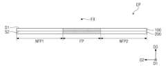
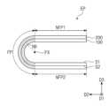
본 발명의 일 실시예에 따른 전자 패널(EP)은 폴딩 축(FX)을 중심으로 폴딩될 수 있다. 전자 패널(EP)은 폴딩부(FP), 제1 평면부(NFP1), 및 제2 평면부(NFP2)를 포함한다. 제1 평면부(NFP1) 및 제2 평면부(NFP2)는 제2 방향(D2)을 따라 배열되고, 폴딩부(FP)는 제1 평면부(NFP1)와 제2 평면부(NFP2) 사이에 배치될 수 있다. 제1 평면부(NFP1), 폴딩부(FP), 및 제2 평면부(NFP2)는 연결되어 일체의 형상을 가질 수 있다. 본 실시예에서는 용이한 설명을 위해 폴딩부(FP)를 음영 처리하여 도시하였다.The electronic panel EP according to an embodiment of the present invention may be folded around the folding axis FX. The electronic panel EP includes a folding part FP, a first flat part NFP1, and a second flat part NFP2. The first flat part NFP1 and the second flat part NFP2 are arranged along the second direction D2, and the folding part FP is between the first flat part NFP1 and the second flat part NFP2. can be placed. The first flat part NFP1, the folding part FP, and the second flat part NFP2 may be connected to have an integrated shape. In this embodiment, the folding portion FP is shown shaded for ease of explanation.
폴딩부(FP)는 폴딩 축(FX)을 중심으로 폴딩될 수 있다. 폴딩부(FP)는 전자 패널(EP)이 폴딩될 때, 형상의 변형이 발생되는 부분일 수 있다. 폴딩부(FP)는 제1 모드에서 폴딩 축(FX)을 중심으로 폴딩되어, 제2 방향(D2) 및 제3 방향(D3)에 의해 정의되는 단면상에서 소정의 반지름(RR)을 가진 반 원 형상을 가질 수 있다. 도 3a에 도시된 반지름(RR)은 내측 반지름을 의미하며, 윈도우 패널(100)의 제1 면(S1)으로부터 폴딩 축(FX)까지의 거리로 정의될 수 있다. 본 실시예에서, 폴딩부(FP)에는 폴딩에 따른 폴딩 스트레스가 인가될 수 있다.The folding unit FP may be folded around the folding axis FX. The folding portion FP may be a portion whose shape is deformed when the electronic panel EP is folded. The folding portion FP is folded about the folding axis FX in the first mode, and is a semicircle with a predetermined radius RR in the cross section defined by the second direction D2 and the third direction D3. It can have a shape. The radius RR shown in FIG. 3A refers to the inner radius and may be defined as the distance from the first surface S1 of the
제1 평면부(NFP1)는 폴딩부(FP)의 일 측에 인접하고, 제2 평면부(NFP2)는 폴딩부(FP)의 타 측에 인접한다. 제1 평면부(NFP1)와 제2 평면부(NFP2)는 폴딩부(FP)를 사이에 두고 제1 방향(D1)에서 서로 이격될 수 있다. 제1 평면부(NFP1)와 제2 평면부(NFP2)는 전자 패널(EP)이 폴딩될 때, 형상의 변형이 발생되지 않는 부분들일 수 있다.The first flat part NFP1 is adjacent to one side of the folding part FP, and the second flat part NFP2 is adjacent to the other side of the folding part FP. The first flat part NFP1 and the second flat part NFP2 may be spaced apart from each other in the first direction D1 with the folding part FP interposed therebetween. The first flat part NFP1 and the second flat part NFP2 may be parts whose shape is not deformed when the electronic panel EP is folded.
본 발명에 따르면, 전자 패널(EP)은 유연성을 가질 수 있다. 이에 따라, 폴딩 축(FX)을 중심으로 폴딩되거나 언폴딩되어 다양한 형상으로 변형될 수 있다.According to the present invention, the electronic panel (EP) can be flexible. Accordingly, it can be folded or unfolded around the folding axis FX and transformed into various shapes.
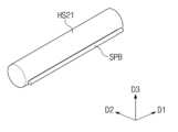
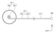
다시 도 1 내지 도 2b를 참조하면, 하우징 유닛(HU)은 전자 패널(EP)을 수용하며, 전자 장치(EA)의 외관을 정의한다. 하우징 유닛(HU)은 형상을 변형시킬 수 있다. 전자 패널(EP)의 형상은 하우징 유닛(HU)의 형상에 의해 결정될 수 있다. 구체적으로, 하우징 유닛(HU)은 제1 하우징 부재(HS1), 제2 하우징 부재(HS2), 및 결합 부재(BN)를 포함할 수 있다.Referring again to FIGS. 1 to 2B, the housing unit (HU) accommodates the electronic panel (EP) and defines the appearance of the electronic device (EA). The housing unit (HU) can change its shape. The shape of the electronic panel EP may be determined by the shape of the housing unit HU. Specifically, the housing unit (HU) may include a first housing member (HS1), a second housing member (HS2), and a coupling member (BN).
제1 하우징 부재(HS1)는 전자 패널(EP)의 일 부분을 수용한다. 전자 패널(EP)의 일 부분은 제1 하우징 부재(HS1) 내에 삽입될 수 있다. 제2 하우징 부재(HS2)는 제1 하우징 부재(HS2)와 제2 방향(D2)에서 서로 이격되어 배치될 수 있다. 제2 하우징 부재(HS2)는 전자 패널(EP)의 다른 일 부분을 수용한다. 전자 패널(EP)의 다른 일 부분은 제2 하우징 부재(HS2) 내에 삽입될 수 있다.The first housing member HS1 accommodates a portion of the electronic panel EP. A portion of the electronic panel EP may be inserted into the first housing member HS1. The second housing member HS2 may be arranged to be spaced apart from the first housing member HS2 in the second direction D2. The second housing member HS2 accommodates another portion of the electronic panel EP. Another part of the electronic panel EP may be inserted into the second housing member HS2.
결합 부재(BN)는 제1 및 제2 하우징 부재들(HS1, HS2) 사이에 배치되어 제1 및 제2 하우징 부재들(HS1, HS2)을 결합시킨다. 한편, 제1 및 제2 하우징 부재들(HS1, HS2)은 결합 부재(BN)에 연결된 상태로 움직일 수 있다. 제1 및 제2 하우징 부재들(HS1, HS2)의 움직임에 따라, 전자 패널(EP)의 폴딩 또는 언폴딩 상태가 결정될 수 있다.The coupling member BN is disposed between the first and second housing members HS1 and HS2 to couple the first and second housing members HS1 and HS2. Meanwhile, the first and second housing members HS1 and HS2 may move while connected to the coupling member BN. Depending on the movement of the first and second housing members HS1 and HS2, the folded or unfolded state of the electronic panel EP may be determined.
결합 부재(BN)는 제1 결합부들(BN11, BN12), 및 제2 결합부들(BN21, BN22)을 포함한다. 제1 결합부들(BN11, BN12)은 제1 및 제2 하우징 부재들(HS1, HS2)을 사이에 두고 제1 방향(D1)에서 서로 이격되어 배치된다. 제1 결합부들(BN11, BN12)은 각각 제1 및 제2 하우징 부재들(HS1, HS2)의 일 측들과 타 측들을 각각 결합시킨다.The coupling member BN includes first coupling parts BN11 and BN12, and second coupling parts BN21 and BN22. The first coupling parts BN11 and BN12 are arranged to be spaced apart from each other in the first direction D1 with the first and second housing members HS1 and HS2 interposed therebetween. The first coupling portions BN11 and BN12 respectively couple one side and the other sides of the first and second housing members HS1 and HS2, respectively.
본 실시예에서, 제1 결합부들(BN11, BN12) 각각은 두 개의 홀들이 정의된 판(plate)으로 도시되고, 제2 결합부들(BN21, BN22) 각각은 볼트들로 도시되었다. 제2 결합부들(BN21, BN22)은 각각 제1 결합부들(BN11, BN12)에 정의된 홀들을 관통하여 제1 및 제2 하우징 부재들(HS1, HS2)과 결합될 수 있다. 다만, 이는 예시적으로 도시한 것이고, 제1 결합부들(BN11, BN12)과 제2 결합부들(BN21, BN22)은 제1 및 제2 하우징 부재들(HS1, HS2)이 폴딩 축(FX)을 중심으로 폴딩 또는 언폴딩 동작을 가능하게 하는 다양한 구성들로 설계될 수 있으며, 어느 하나의 실시예로 한정되지 않는다.In this embodiment, each of the first coupling parts BN11 and BN12 is shown as a plate with two holes defined, and each of the second coupling parts BN21 and BN22 is shown as a bolt. The second coupling parts BN21 and BN22 may be coupled to the first and second housing members HS1 and HS2 by passing through holes defined in the first coupling parts BN11 and BN12, respectively. However, this is shown as an example, and the first coupling parts (BN11, BN12) and the second coupling parts (BN21, BN22) are connected to the folding axis FX by the first and second housing members (HS1, HS2). It can be designed with various configurations that enable folding or unfolding operations around the center, and is not limited to any one embodiment.
도 2a에는 전자 장치(EA)가 언폴딩된 상태를 도시하였다. 도 2a에 도시된 것과 같이, 언폴딩된 상태에서 전자 장치(EA)는 전자 패널(EP)의 전면을 외부에 노출시킨다. 사용자는 전자 패널(EP)에 제공되는 영상(IM)을 용이하게 시인할 수 있다.Figure 2a shows the electronic device (EA) in an unfolded state. As shown in FIG. 2A, in the unfolded state, the electronic device EA exposes the front of the electronic panel EP to the outside. The user can easily view the image (IM) provided on the electronic panel (EP).
도 2b에는 전자 장치(EA)가 폴딩된 상태를 도시하였다. 도 2b에 도시된 것과 같이, 폴딩된 상태에서 전자 장치(EA)는 전자 패널(EP)은 하우징 유닛(HU)에 의해 커버되어 외부에서 시인되지 않는다.Figure 2b shows the electronic device (EA) in a folded state. As shown in FIG. 2B, in the folded state of the electronic device EA, the electronic panel EP is covered by the housing unit HU and is not visible from the outside.
본 발명의 일 실시예에 따른 전자 장치(EA)는 유연한 전자 패널(EP) 및 형상이 변형되는 하우징 유닛(HU)을 포함함으로써, 전자 패널(EP)을 폴딩하거나 언폴딩시킬 수 있다. 이에 따라, 전자 장치(EA)의 휴대성이 향상되고 다양한 환경에서의 전자 장치(EA)의 활용성이 향상될 수 있다.The electronic device EA according to an embodiment of the present invention includes a flexible electronic panel EP and a housing unit HU whose shape is deformable, thereby allowing the electronic panel EP to be folded or unfolded. Accordingly, the portability of the electronic device (EA) can be improved and the usability of the electronic device (EA) in various environments can be improved.
도 4a는 도 3a에 전자 패널의 일부를 개략적으로 도시한 평면도이고, 도 4b는 본 발명의 일 실시예에 따른 전자 패널의 일부 구성을 도시한 신호 회로도이고, 도 4c는 도 4a의 일부를 간략히 도시한 단면도이다. 도 4a 내지 도 4c에는 표시 패널(200)의 일부 영역들 및 일부 구성들을 간략히 도시하였다. 이하, 도 4a 내지 도4c를 참조하여 본 발명의 일 실시예에 따른 전자 패널에 대해 설명한다. 한편, 도 1 내지 도 3b에서 설명한 구성과 동일한 구성에 대해서는 동일한 참조부호를 부여하고 중복된 설명은 생략하기로 한다.FIG. 4A is a plan view schematically showing a portion of the electronic panel in FIG. 3A, FIG. 4B is a signal circuit diagram illustrating a portion of the electronic panel according to an embodiment of the present invention, and FIG. 4C is a brief diagram of a portion of FIG. 4A. This is a cross-sectional view. FIGS. 4A to 4C briefly show some areas and some configurations of the
도 4a에 도시된 것과 같이, 전자 패널(EP)은 평면상에서 복수의 발광영역들(LA(i,j)~LA(i+1,j+2)) 및 발광영역들(LA(i,j)~LA(i+1,j+2))을 에워싸는 비 발광영역(NLA)으로 구분될 수 있다. 도 4a에는 6개의 발광영역들(LA(i,j)~LA(i+1,j+2))이 제공된 부분을 예시적으로 도시하였다.As shown in FIG. 4A, the electronic panel EP has a plurality of light emitting areas (LA(i,j) to LA(i+1,j+2)) and light emitting areas (LA(i,j) on a plane. )~LA(i+1,j+2)) can be divided into a non-luminous area (NLA) surrounding it. Figure 4a exemplarily shows a portion provided with six light-emitting areas (LA(i,j) to LA(i+1,j+2)).
발광영역들(LA(i,j)~LA(i+1,j+2))은 각각 소정의 광을 방출한다. 6개의 발광영역들(LA(i,j)~LA(i+1,j+2))은 서로 동일하거나 상이한 컬러의 광들을 방출할 수 있다.The light emitting areas (LA(i,j) to LA(i+1,j+2)) each emit a certain amount of light. The six light-emitting areas (LA(i,j) to LA(i+1,j+2)) may emit lights of the same or different colors.
비 발광영역(NLA)은 실질적으로 발광영역들(LA(i,j)~LA(i+1,j+2))을 구분하는 구성일 수 있다. 비 발광영역(NLA)은 발광영역들(LA(i,j)~LA(i+1,j+2)) 주변으로 방출되는 광을 차단하여 빛샘 등을 방지하고, 발광영역들(LA(i,j)~LA(i+1,j+2))이 분명하게 구획되도록 한다.The non-emissive area (NLA) may be configured to substantially separate the light-emitting areas (LA(i,j) to LA(i+1,j+2)). The non-emissive area (NLA) blocks light emitted around the emitting areas (LA(i,j) to LA(i+1,j+2) to prevent light leakage, etc., and the non-emissive area (LA(i) ,j)~LA(i+1,j+2)) are clearly demarcated.
발광영역들(LA(i,j)~LA(i+1,j+2)) 각각에는 광을 생성하는 표시소자가 각각 배치될 수 있다. 본 실시예에서, 표시소자는 유기발광소자일 수 있다. 표시소자들에 전기적 신호를 제공하는 신호 배선들은 비 발광영역(NLA)에 중첩하게 배치될 수 있다.A display element that generates light may be disposed in each of the light-emitting areas (LA(i,j) to LA(i+1,j+2)). In this embodiment, the display device may be an organic light emitting device. Signal wires that provide electrical signals to the display elements may be arranged to overlap the non-emissive area (NLA).
도 4b에는 화소(PX(i,j))의 등가회로가 예시적으로 도시되었다. 화소(PX(i,j))는 i번째 게이트 라인(GLi)으로부터 게이트 신호를 수신하고, j번째 데이터 라인(DLj)으로부터 데이터 신호를 수신한다. 화소(PX(i,j))는 전원라인(KL)으로부터 제1 전원전압(ELVDD)을 수신한다.In Figure 4b, the equivalent circuit of the pixel (PX(i,j)) is shown as an example. The pixel PX(i,j) receives a gate signal from the ith gate line GLi and a data signal from the jth data line DLj. The pixel (PX(i,j)) receives the first power voltage (ELVDD) from the power line (KL).
화소(PX(i,j))는 제1 트랜지스터(TR1), 제2 트랜지스터(TR2), 커패시터(CP), 및 표시 소자(ED)를 포함한다. 본 실시예에서, 표시 소자(ED)는 유기발광소자로 예시적으로 도시되었다. 다만, 이는 예시적으로 도시한 것이고, 본 발명의 일 실시예에 따른 표시 소자(ED)는 액정 커패시터, 전기영동소자, 전기습윤소자, 또는 무기발광소자를 포함할 수도 있다. 한편, 화소(PX(i,j))의 구성은 이에 제한되지 않고 변형되어 실시될 수 있다.The pixel PX(i,j) includes a first transistor TR1, a second transistor TR2, a capacitor CP, and a display element ED. In this embodiment, the display device ED is exemplarily shown as an organic light emitting device. However, this is shown as an example, and the display element (ED) according to an embodiment of the present invention may include a liquid crystal capacitor, an electrophoresis element, an electrowetting element, or an inorganic light emitting element. Meanwhile, the configuration of the pixel PX(i,j) is not limited to this and may be modified.
제1 트랜지스터(TR1)는 i번째 게이트 라인(GLi)에 인가된 게이트 신호에 응답하여 j번째 데이터 라인(DLj)에 인가된 데이터 신호를 출력한다. 커패시터(CP)는 제1 트랜지스터(TR1)로부터 수신한 데이터 신호에 대응하는 전압을 충전한다.The first transistor TR1 outputs a data signal applied to the j-th data line DLj in response to the gate signal applied to the i-th gate line GLi. The capacitor CP charges a voltage corresponding to the data signal received from the first transistor TR1.
제2 트랜지스터(TR2)는 표시 소자(ED)에 연결된다. 제2 트랜지스터(TR2)는 커패시터(CP)에 저장된 전하량에 대응하여 표시 소자(ED)에 흐르는 구동전류를 제어한다. 표시 소자(ED)는 제2 트랜지스터(TR2)의 턴-온 구간 동안 발광한다.The second transistor TR2 is connected to the display element ED. The second transistor TR2 controls the driving current flowing through the display element ED in response to the amount of charge stored in the capacitor CP. The display element ED emits light during the turn-on period of the second transistor TR2.
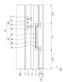
도 4c에는 도 4a에 도시된 표시 패널(200)의 일부를 자른 단면도로, 일 화소(PX)가 배치된 영역을 도시하였으며, 도 4b에 도시된 등가 회로의 구성들 중 제2 트랜지스터(TR2, 이하 박막 트랜지스터)와 표시 소자(ED)를 도시하였다. 도 4c에 도시된 것과 같이, 표시 패널(200)은 베이스 기판(SUB), 복수의 절연층들(IL1, IL2, IL3, IL4), 화소(PX), 및 봉지층(ECL)을 포함할 수 있다.FIG. 4C is a cross-sectional view of a portion of the
베이스 기판(SUB)은 유연성을 갖고 절연성을 가질 수 있다. 베이스 기판(SUB)은 예를 들어, 폴리이미드(polyimide, PI)와 같은 수지를 포함할 수 있다. 절연층들(IL1, IL2, IL3, IL4)은 제3 방향(D3)을 따라 순차적으로 적층된 제1 내지 제4 절연층들(IL1, IL2, IL3, IL4)을 포함할 수 있다. 제1 내지 제4 절연층들(IL1, IL2, IL3, IL4) 각각은 무기막 및/또는 유기막을 포함할 수 있으며, 단층 또는 다층 구조를 가질 수 있다.The base substrate (SUB) may be flexible and have insulating properties. The base substrate (SUB) may include a resin such as polyimide (PI). The insulating layers IL1, IL2, IL3, and IL4 may include first to fourth insulating layers IL1, IL2, IL3, and IL4 sequentially stacked along the third direction D3. Each of the first to fourth insulating layers IL1, IL2, IL3, and IL4 may include an inorganic layer and/or an organic layer, and may have a single-layer or multi-layer structure.
베이스 기판(SUB) 상에 박막 트랜지스터(TR2)가 배치된다. 박막 트랜지스터(TR2)는 반도체 패턴(SP), 제어 전극(CE), 입력 전극(IE), 및 출력 전극(CE)을 포함할 수 있다.A thin film transistor TR2 is disposed on the base substrate SUB. The thin film transistor TR2 may include a semiconductor pattern (SP), a control electrode (CE), an input electrode (IE), and an output electrode (CE).
반도체 패턴(SP)은 베이스 기판(SUB)과 제1 절연층(IL1) 사이에 배치된다. 제어 전극(CE)은 반도체 패턴(SP)과 평면상에서 중첩하여 배치된다. 제어 전극(CE)은 제1 절연층(IL1)과 제2 절연층(IL2) 사이에 배치될 수 있다. 다만, 이는 예시적으로 도시한 것이고, 제어 전극(CE)과 반도체 패턴(SP)의 층 관계는 변경될 수도 있다. 예를 들어, 반도체 패턴(SP)이 제어 전극(CE) 상에 배치될 수도 있으며, 어느 하나의 실시예로 한정되지 않는다.The semiconductor pattern SP is disposed between the base substrate SUB and the first insulating layer IL1. The control electrode (CE) is disposed to overlap the semiconductor pattern (SP) on a plane. The control electrode CE may be disposed between the first insulating layer IL1 and the second insulating layer IL2. However, this is shown as an example, and the layer relationship between the control electrode (CE) and the semiconductor pattern (SP) may be changed. For example, the semiconductor pattern SP may be disposed on the control electrode CE, and is not limited to any one embodiment.
입력 전극(IE) 및 출력 전극(OE)은 제2 절연층(Il2)과 제3 절연층(IL3) 사이에 배치된다. 입력 전극(IE) 및 출력 전극(OE)은 동일 층 상에 배치되어 평면상에서 서로 이격될 수 있다. 입력 전극(IE) 및 출력 전극(OE) 각각은 제1 절연층(IL1)과 제2 절연층(IL2)을 관통하여 반도체 패턴(SP)에 접속된다.The input electrode (IE) and the output electrode (OE) are disposed between the second insulating layer (Il2) and the third insulating layer (IL3). The input electrode (IE) and the output electrode (OE) may be disposed on the same layer and spaced apart from each other on a plane. Each of the input electrode IE and the output electrode OE is connected to the semiconductor pattern SP through the first insulating layer IL1 and the second insulating layer IL2.
표시 소자(ED)는 제3 절연층(IL3) 상에 배치된다. 표시 소자(ED)는 제1 전극(ED1), 제2 전극(ED2), 및 발광층(EM)을 포함할 수 있다. 표시 소자(ED)의 발광 방향에 따라, 제1 전극(ED1)과 제2 전극(ED2)의 위치는 서로 바뀔 수 있다. 제1 전극(ED1)은 제3 절연층(IL4) 상에 배치된다. 제1 전극(ED1)은 제3 절연층(IL3)을 관통하여 박막 트랜지스터(TR2)에 접속될 수 있다.The display element ED is disposed on the third insulating layer IL3. The display element ED may include a first electrode ED1, a second electrode ED2, and an emission layer EM. Depending on the direction of light emission of the display element ED, the positions of the first electrode ED1 and the second electrode ED2 may be changed. The first electrode ED1 is disposed on the third insulating layer IL4. The first electrode ED1 may penetrate the third insulating layer IL3 and be connected to the thin film transistor TR2.
제4 절연층(IL4)에는 제1 전극(ED1)의 적어도 일부를 노출시키는 개구부(OP)가 정의될 수 있다. 발광층(EM)은 개구부(OP)에 배치될 수 있다. 발광 영역(LA)은 발광층(EM)과 대응되어 정의될 수 있다.An opening OP exposing at least a portion of the first electrode ED1 may be defined in the fourth insulating layer IL4. The light emitting layer (EM) may be disposed in the opening (OP). The light emitting area (LA) may be defined in correspondence with the light emitting layer (EM).
제2 전극(ED2)은 제4 절연층(IL) 상에 배치된다. 제2 전극(CE)은 발광 영역(LA)뿐만 아니라 비 발광 영역(NLA)에도 배치된다.The second electrode ED2 is disposed on the fourth insulating layer IL. The second electrode CE is disposed not only in the light emitting area LA but also in the non-light emitting area NLA.
봉지층(ECL)은 제2 전극(ED2) 상에 배치된다. 봉지층(ECL)은 발광영역(LA)와 비 발광영역(NLA)에 모두 중첩한다. 봉지층(ECL)은 표시 소자(ED)를 봉지하여 외부 오염이나 수분이 표시 소자(ED)에 침투되는 것을 방지하고, 표시 패널(200)의 전면에 평탄면을 제공할 수 있다.The encapsulation layer (ECL) is disposed on the second electrode (ED2). The encapsulation layer (ECL) overlaps both the emitting area (LA) and the non-emitting area (NLA). The encapsulation layer (ECL) seals the display element (ED) to prevent external contamination or moisture from penetrating into the display element (ED), and can provide a flat surface on the front of the
봉지층(ECL)은 제1 무기막(IOL1), 제2 무기막(IOL2), 및 유기막(OL)을 포함할 수 있다. 유기막(OL)은 제1 무기막(IOL1)과 제2 무기막(IOL2) 사이에 배치된다. 한편, 이는 예시적으로 도시한 것이고, 본 발명의 일 실시예에 따른 봉지층(ECL)은 유리 기판을 포함할 수도 있다. 이때, 봉지층(ECL)은 표시 소자(ED)로부터 소정의 간격으로 이격되어 배치될 수도 있으며, 어느 하나의 실시예로 한정되지 않는다.The encapsulation layer (ECL) may include a first inorganic layer (IOL1), a second inorganic layer (IOL2), and an organic layer (OL). The organic layer OL is disposed between the first inorganic layer IOL1 and the second inorganic layer IOL2. Meanwhile, this is shown as an example, and the encapsulation layer (ECL) according to an embodiment of the present invention may include a glass substrate. At this time, the encapsulation layer (ECL) may be arranged to be spaced apart from the display element (ED) at a predetermined interval, and is not limited to any one embodiment.
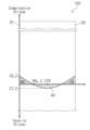
도 5a는 비교 실시예에 따른 윈도우 패널의 내부 응력 거동을 도시한 그래프이고, 도 5b는 본 발명의 일 실시예에 따른 윈도우 패널의 내부 응력 거동을 간략히 도시한 그래프이다. 도 5a 및 도 5b 각각에는 비교 실시예의 윈도우 패널(100-A, 이하 비교 패널)과 본 발명의 일 실시예에 따른 윈도우 패널(100)을 점선 처리하여 도시하였다. 이하, 도 5a 및 도 5b를 참조하여 본 발명에 대해 설명한다.FIG. 5A is a graph showing the internal stress behavior of a window panel according to a comparative example, and FIG. 5B is a graph briefly showing the internal stress behavior of a window panel according to an embodiment of the present invention. In each of FIGS. 5A and 5B , a window panel 100-A (hereinafter referred to as a comparative panel) of a comparative example and a
도 5a 및 도 5b에 도시된 것과 같이, 패널(100, 100-A)에 나타나는 내부 응력은 깊이(depth)에 따라 달라질 수 있다. 내부 응력은 압축 응력(compressive stress) 및 인장 응력(tensile stress)을 포함한다.As shown in FIGS. 5A and 5B, internal stress appearing in the
한편, 깊이는 패널(100-A, 100)의 표면들로부터 패널(100-A, 100)의 내부를 향할 때 표면들로부터의 거리를 의미한다. 예를 들어, 비교 패널(100-A)에 있어서, 깊이 방향(depth direction)은 제1 면(S1-C) 및 제2 면(S2-C) 각각으로부터 제3 방향(D3)과 평행한 방향을 따라 비교 패널(100-A)의 중심 지점(CTR)을 향하는 방향으로 정의될 수 있다. 중심 지점(CTR)은 비교 패널(100-A)의 두께의 1/2이 되는 지점일 수 있다.Meanwhile, depth refers to the distance from the surfaces of the panel 100-A, 100 when heading toward the inside of the panel 100-A, 100. For example, in the comparison panel 100-A, the depth direction is a direction parallel to the third direction D3 from each of the first surface S1-C and the second surface S2-C. It may be defined as a direction toward the center point (CTR) of the comparison panel 100-A. The center point (CTR) may be a point that is half the thickness of the comparison panel 100-A.
마찬가지로, 윈도우 패널(100)에 있어서, 깊이 방향은 제1 면(S1) 및 제2 면(S2) 각각으로부터 제3 방향(D3)과 평행한 방향을 따라 윈도우 패널(100)의 중심 지점(CTR)을 향하는 방향으로 정의될 수 있다. 깊이는 윈도우 패널(100)의 두께의 1/2이 되는 중심 지점(CTR)을 중심으로 좌우 대칭이 되는 위치로 정의될 수 있다.Likewise, in the
패널(100, 100-A)의 응력 거동은 표면 압축 응력(Surface compressive stress)을 갖고, 압축 깊이(Depth of compression, DOC)를 가지며, 이온 침투 깊이(Depth of layer, DOL), 및 중심 인장 응력(Central tensile stress)을 가질 수 있다. 표면 압축 응력은 표면에 존재하는 압축 응력으로, 제1 면(S1, S1_A), 및 제2 면(S2, S2_A)에 존재하는 압축 응력일 수 있다. 도 5a 및 도 5b에는 비교 패널(100-A)의 표면 압축 응력(CS_A, 이하 제1 표면 압축 응력) 및 본 발명의 일 실시예에 따른 패널(100)의 표면 압축 응력(CS_B, 이하 제2 표면 압축 응력)을 각각 표시하였다.The stress behavior of the
압축 깊이는 내부 응력이 0(zero)이 되는 지점으로, 압축 응력과 인장 응력이 평형을 이루는 지점일 수 있다. 내부 응력 거동을 압축 응력을 기준으로 하는 경우, 압축 깊이는 압축 응력이 0이 되는 지점으로 정의될 수 있다.The compression depth is the point where the internal stress becomes 0 (zero), and may be the point where the compressive stress and tensile stress are in balance. If the internal stress behavior is based on compressive stress, the compression depth can be defined as the point where the compressive stress becomes zero.
이온 침투 깊이는 강화 공정 시 패널(100, 100-A)에 침투된 이온, 예를 들어 알칼리 금속 이온이 패널(100, 100-A) 내부에 도달한 깊이를 의미할 수 있다. 도 5a 및 도 5b에는 비교 패널(100-A)의 압축 깊이(DOC_A, 이하 제1 압축 깊이) 및 본 발명의 일 실시예에 따른 패널(100)의 압축 깊이(DOC_B, 이하 제2 압축 깊이)를 각각 표시하였다.The ion penetration depth may refer to the depth at which ions, for example, alkali metal ions, penetrated into the
중심 인장 응력은 압축 응력에 대응하여 패널(100, 100-A)의 내부에 형성되는 내부 응력일 수 있으며, 대체로, 압축 응력과 대향되는 인장 응력으로 나타난다. 도 5a 및 도 5b에는 비교 패널(100-A)의 중심 인장 응력(CT_A) 및 본 발명의 일 실시예에 따른 패널(100)의 중심 인장 응력(CT_B)을 각각 표시하였다.The central tensile stress may be an internal stress formed inside the panel (100, 100-A) in response to the compressive stress, and generally appears as a tensile stress opposite to the compressive stress. 5A and 5B show the central tensile stress (CT_A) of the comparative panel 100-A and the central tensile stress (CT_B) of the
압축 깊이(DOC_A, DOC_B) 이상의 깊이 범위에서의 인장 응력 거동에 의한 면적(AA)은 제1 면(S1)으로부터 압축 깊이(DOC_A) 범위까지의 압축 응력 거동에 의한 면적(BA) 및 제2 면(S2)으로부터 압축 깊이 범위까지의 압축 응력 거동에 의한 면적(CA)의 합이 서로 유사하게 설계됨으로써, 패널(100, 100-A)의 강도는 향상될 수 있다. 이에 따라, 비교 패널(100-A)의 내부 응력이 패널(100, 100-A) 내에서 균형을 이룰 수 있으며, 비교 패널(100-A)의 파단(self-destruction) 등의 문제가 방지될 수 있다. 패널(100, 100-A)은 압축 응력에 대응하여 인장 응력을 형성함으로써, 압축 응력에 따른 변형을 최소화하고, 패널(100, 100-A)에 미치는 응력들 간의 균형을 이룰 수 있다.The area (AA) due to the tensile stress behavior in the depth range of compression depth (DOC_A, DOC_B) or more is the area (BA) due to compressive stress behavior from the first surface (S1) to the compression depth (DOC_A) range and the second surface The strength of the
도 5a에 도시된 것과 같이, 비교 패널(100-A)은 표면에서 제1 표면 압축 응력(CS_A)을 갖고, 제1 압축 깊이(DOC_A), 및 제1 중심 인장 응력(CT_A)을 가진 것으로 도시되었다. 비교 패널(100-A)에서의 응력 변화는 제1 압축 깊이(DOC_A) 보다 깊은 구간 내에서 일정한 값을 갖는 것으로 도시되었다. 이때의 응력 값은 제1 중심 인장 응력(CT_A)으로 유지될 수 있다.As shown in Figure 5A, comparison panel 100-A is shown as having a first surface compressive stress (CS_A), a first depth of compression (DOC_A), and a first central tensile stress (CT_A) at the surface. It has been done. The stress change in the comparison panel 100-A was shown to have a constant value within a section deeper than the first compression depth DOC_A. The stress value at this time may be maintained as the first central tensile stress (CT_A).
도 5a에 도시된 비교 패널(100-A)의 내부 응력 거동은 화학 강화된 유리 기판의 거동과 대응될 수 있다. 구체적으로, 비교 패널(100-A)의 내부 응력 거동은 압축 깊이(DOC_A) 이상의 깊이 범위에서 응력의 변화가 거의 일정하게 유지되는 양상을 보인다. 구체적으로, 압축 깊이(DOC_A) 이상의 깊이 범위에서 비교 패널(100-A)의 내부 응력은 제1 중심 인장 응력(CT_A)으로 일정하게 유지될 수 있다.The internal stress behavior of the comparative panel 100-A shown in FIG. 5A may correspond to the behavior of a chemically strengthened glass substrate. Specifically, the internal stress behavior of the comparison panel 100-A shows that the change in stress remains almost constant in a depth range greater than the compression depth (DOC_A). Specifically, the internal stress of the comparison panel 100-A may be kept constant at the first central tensile stress CT_A in a depth range greater than the compression depth DOC_A.
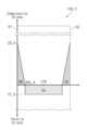
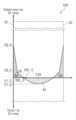
이와 달리, 도 5b를 참조하면, 본 발명의 일 실시예에 따른 윈도우 패널(100)은 제2 표면 압축 응력(CS_B), 제2 이온 침투 깊이, 제2 압축 깊이(DOC_B), 및 제2 중심 인장 응력(CT_B)을 가질 수 있다. 제2 표면 압축 응력(CS_B)은 제1 표면 압축 응력(CS_A)보다 작을 수 있다. 제2 표면 압축 응력(CS_B)은 약 200MPa 이상일 수 있다.In contrast, referring to FIG. 5B, the
제2 압축 깊이(DOC_B)는 제1 압축 깊이(DOC_A)보다 클 수 있다. 제2 중심 인장 응력(CT_B)은 제1 중심 인장 응력(CT_A)보다 작을 수 있다.The second compression depth (DOC_B) may be greater than the first compression depth (DOC_A). The second central tensile stress (CT_B) may be smaller than the first central tensile stress (CT_A).
윈도우 패널(100)에 있어서, 제2 압축 깊이(DOC_B)는 하기 관계식을 만족할 수 있다.In the
[관계식][Relational Expression]
0.15T < DOC_B < 0.3T, T: 윈도우 패널의 두께0.15T < DOC_B < 0.3T, T: Thickness of window panel
관계식에 따르면, 제2 압축 깊이(DOC_B)는 윈도우 패널(100)의 두께의 15% 이상 두께의 30% 이하의 범위 내의 깊이로 설계될 수 있다.According to the relational equation, the second compression depth DOC_B may be designed to be a depth within a range of 15% to 30% of the thickness of the
본 발명의 일 실시예에 따른 윈도우 패널(100)의 응력 거동은 표면 압축 응력을 나타내는 표면으로부터 압축 응력과 인장응력의 크기가 동일하여 평형을 이루는 압축 깊이까지의 범위 내에서 기울기가 일정하거나 기울기 변화가 크지 않은 양상을 보일 수 있다. 또한, 윈도우 패널(100)의 응력 거동은 압축 깊이로부터 윈도우 패널(100)의 두께가 1/2이 되는 지점까지의 범위 내에서 응력의 크기가 변화되는 양상을 보일 수 있다. 이러한 거동은 실질적으로 열 강화에 따른 응력 거동 프로파일과 대응될 수 있다.The stress behavior of the
구체적으로, 윈도우 패널(100)의 응력 거동은 제2 압축 깊이(DOC_B) 이상의 깊이 범위에서도 변화되는 양상을 보일 수 있다. 본 실시예에서, 윈도우 패널(100)에 있어서, 인장 응력은 윈도우 패널(100)의 중심에 가까워질수록 커지고, 윈도우 패널(100)의 중심에서 최대 인장 응력을 가지며, 제2 중심 인장 응력(CT_B)과 대응될 수 있다. 윈도우 패널(100)의 응력 거동은 열 강화된 유리 기판의 거동과 대응될 수 있다.Specifically, the stress behavior of the
응력 거동에 표시되지 않았으나, 윈도우 패널(100)은 강화 처리 시 이온 침투 깊이가 소정의 깊이 이상이 되도록 제어될 수 있다. 본 발명의 일 실시예에 따른 윈도우 패널(100)이 단일 염을 이용한 강화 처리 공정을 거치는 경우, 이온 침투 깊이는 0.5T이상으로 제어될 수 있다. 또는, 본 발명의 일 실시예에 따른 윈도우 패널(100)이 혼합 염을 이용한 강화 처리 공정을 거치는 경우, 이온 침투 깊이는 0.3T이상으로 제어될 수 있다. 윈도우 패널(100)은 이온 침투 깊이를 소정의 깊이 이상이 되도록 제어됨으로써, 열 강화된 응력 거동 프로파일을 가질 수 있고, 박막의 두께에서도 향상된 강도와 내 충격성을 가질 수 있다.Although not indicated in the stress behavior, the
하기 표 1은 단일 염을 이용한 강화 처리 공정을 서로 상이한 두께들을 가진 두 가지의 그룹(EX_A, EX_B)에 속한 샘플들에 진행한 결과들을 도시한 것이다. 하기 표 1을 참조하여, 이온 침투 깊이를 두께의 1/2 이상으로 설계하는 단일 염을 이용한 강화 처리 공정에 대해 설명한다.Table 1 below shows the results of performing a strengthening treatment process using a single salt on samples belonging to two groups (EX_A, EX_B) with different thicknesses. Referring to Table 1 below, a strengthening treatment process using a single salt is described in which the ion penetration depth is designed to be more than 1/2 of the thickness.
상기 표 1을 참조하면, 제1 그룹(EX_A)은 약 700㎛의 두께를 가진 유리 재질의 샘플들 각각에 단일 염을 이용한 강화 처리 공정을 적용한 결과들을 포함한다. 제2 그룹(EX_B)은 약 50㎛의 두께를 가진 유리 재질의 샘플들 각각에 단일 염을 이용한 강화 처리 공정을 적용한 결과들을 포함한다.제1 그룹(EX_A)을 참조하면, 약 700㎛의 두께를 가진 유리 재질의 샘플들에서 강화 처리 공정 시간이 증가될수록 표면 압축 응력(CS)은 점차 감소된다. 이와 달리, 이온 침투 깊이(DOL)나 중심 인장 응력(CT)은 강화 처리 공정 시간이 증가될수록 점차 증가되는 양상으로 나타난다.Referring to Table 1, the first group (EX_A) includes the results of applying a strengthening treatment process using a single salt to each of the glass samples with a thickness of about 700㎛. The second group (EX_B) includes the results of applying a strengthening treatment process using a single salt to each of the glass samples with a thickness of about 50 ㎛. Referring to the first group (EX_A), the thickness of about 700 ㎛ As the strengthening treatment process time increases in samples made of glass, the surface compressive stress (CS) gradually decreases. In contrast, the depth of ion penetration (DOL) or central tensile stress (CT) appears to gradually increase as the reinforcement treatment process time increases.
상술한 바와 같이, 강화 처리 공정이 샘플들을 단일 염에 노출시키는 공정에 해당되는 점에서, 공정 시간이 증가될수록 단일 염이 샘플들 내부로 침투하여 도달하게 되는 깊이에 해당되는 이온 깊이(DOL)는 공정 시간이 증가할수록 증가된다.As described above, given that the strengthening treatment process corresponds to a process of exposing samples to a single salt, as the process time increases, the ion depth (DOL), which corresponds to the depth at which the single salt penetrates into the samples, increases. It increases as the process time increases.
이와 달리, 제2 그룹(EX_B)을 참조하면, 약 50㎛의 두께를 가진 유리 재질의 샘플들에서 강화 처리 공정 시간이 증가될수록 표면 압축 응력(CS)은 감소하다 일정 구간(120분~180분)에서 자파 불량이 발생되는 것을 볼 수 있다. 그러나, 180분을 초과하는 구간(240분~360분)에서는 자파 불량이 발생되지 않아 표면 압축 응력의 측정이 가능해지고, 이 구간에서도 공정 시간이 증가될수록 표면 압축 응력(CS)이 점차 감소하는 양상으로 나타난다.On the other hand, referring to the second group (EX_B), as the strengthening treatment process time increases in glass samples with a thickness of about 50㎛, the surface compressive stress (CS) decreases over a certain period (120 to 180 minutes). ), you can see that a self-wave defect occurs. However, in the section exceeding 180 minutes (240 to 360 minutes), no self-rupture defects occur, making it possible to measure the surface compressive stress. Even in this section, as the process time increases, the surface compressive stress (CS) gradually decreases. It appears as
자파 불량 발생 구간(120분~180분)에서는 자파 불량 발생으로 인해 샘플이 손상된 상태이므로, 압축 응력(CS), 이온 침투 깊이(DOL), 및 중심 인장 응력(CT)의 측정이 어려워 상기 표 1에 결과값이 기재되지 않았다. 이 중 이온 침투 깊이(DOL)는 제1 그룹(EX_A)에서와 유사하게 나타날 수 있다. 본 실시예에서, 이온 침투 깊이(DOL)를 표면으로부터 이온이 침투 가능한 최대 깊이로 볼 때, 자파 불량이 발생되지 않았다면, 제1 그룹(EX_A)에서와 대응되게 약 21㎛, 약 26㎛ 정도의 수치로 나타날 것으로 예상될 수 있다.In the section where magnetic wave defects occur (120 minutes to 180 minutes), the sample is damaged due to magnetic wave defects, so it is difficult to measure compressive stress (CS), depth of ion penetration (DOL), and central tensile stress (CT), as shown in Table 1 above. The results were not recorded. Among these, the ion penetration depth (DOL) may appear similar to that in the first group (EX_A). In this embodiment, when considering the ion penetration depth (DOL) as the maximum depth at which ions can penetrate from the surface, if no self-wave defects occur, the ion penetration depth (DOL) is about 21㎛, corresponding to about 26㎛, as in the first group (EX_A). It can be expected to appear numerically.
자파 불량 발생 이후 구간(240분~360분)에서는 자파 불량이 발생되지 않아 이온 침투 깊이(DOL) 측정이 가능하나, 700㎛ 두께의 제1 그룹(EX_A)에서 측정된 이온 침투 깊이(DOL)보다 낮게 나타나고, 처리 시간이 증가됨에 따라 오히려 감소된 양상으로 나타난다. 이는 샘플의 두께 범위 내에서 해당 이온의 농도가 가장 높은 지점을 이온 침투 깊이(DOL)로 보는 이온 침투 깊이(DOL) 측정 방법에 따른 오류일 수 있다.In the section after the self-wave defect occurred (240 minutes to 360 minutes), the depth of ion penetration (DOL) could be measured because no defects occurred in the self-wave, but it was higher than the depth of ion penetration (DOL) measured in the first group (EX_A) with a thickness of 700㎛. It appears low, and appears to actually decrease as processing time increases. This may be an error due to the depth of ion penetration (DOL) measurement method, which views the point with the highest concentration of the ion within the thickness range of the sample as the depth of ion penetration (DOL).
구체적으로, 50㎛ 두께를 가진 제1 그룹(EX_A) 내에서 이온 침투 깊이(DOL)가 샘플 두께의 반인 25㎛ 이상으로 설계되는 경우, 일 면으로부터 침투된 이온의 침투 영역과 타 면으로부터 침투된 이온의 침투 영역이 서로 중첩됨에 따라, 가장 높은 이온 농도를 가진 지점은 샘플 두께의 반보다 낮은 25㎛ 이하로 측정된다. 또한, 강화 공정 시간이 증가될수록 이온 침투 깊이(DOL)가 증가되도록 설계되므로, 이온 침투 깊이(DOL)로 측정되는 결과값은 감소되는 양상으로 나타난다.Specifically, in the case where the ion penetration depth (DOL) within the first group (EX_A) with a thickness of 50㎛ is designed to be 25㎛ or more, which is half the sample thickness, the penetration area of ions penetrated from one side and the penetration area of ions penetrated from the other side As the ion penetration areas overlap, the point with the highest ion concentration is measured below 25 μm, less than half the sample thickness. In addition, since the depth of ion penetration (DOL) is designed to increase as the strengthening process time increases, the result measured by the depth of ion penetration (DOL) appears to decrease.
본 발명의 일 실시예에 따른 단일 염을 이용한 강화 처리 단계에 있어서, 실제 측정된 깊이와 설계된 깊이는 서로 상이할 수 있다. 0.5T 이내의 범위 내에서는 설계된 깊이와 실제 측정된 깊이가 서로 대응될 수 있으나, 0.5T 이상의 범위에서는 설계된 깊이보다 실제 측정된 깊이가 더 작게 나타날 수 있다. 이는 이온 침투 깊이(DOL)의 실제 측정이 샘플의 두께 범위 내에서 가장 높은 이온 농도를 가진 지점을 찾는 것으로 이루어짐에 따라 나타나는 오차일 수 있다.In the strengthening treatment step using a single salt according to an embodiment of the present invention, the actual measured depth and the designed depth may be different from each other. Within the range of 0.5T, the designed depth and the actual measured depth may correspond to each other, but within the range of 0.5T or more, the actual measured depth may appear smaller than the designed depth. This may be an error as the actual measurement of depth of ion penetration (DOL) consists of finding the point with the highest ion concentration within the thickness of the sample.
이하 본 명세서에서는 이온 침투 깊이를 설계값과 측정값으로 구분한다. 설계값은 해당 이온 침투 깊이를 갖도록 이온 농도나 온도 시간을 제어하는 것이고, 측정값은 강화 처리를 거친 기재를 표면 응력 측정 장치(FSM) 등의 측정장비를 통해 측정한 결과값을 의미할 수 있다. 본 명세서에서 의미하는 이온 침투 깊이는 실질적으로, 설계된 깊이와 대응될 수 있다. 즉, 본 발명의 일 실시예에 따른 이온 침투 깊이(DOL)는 이온이 침투 가능한 최대 깊이로 해석될 수 있다. 본 발명에 따르면, 단일 염을 이용한 강화 처리 공정 시 이온 침투 깊이(DOL)를 0.5T 이상으로 설계되도록 공정 시간과 온도를 제어함으로써, 100㎛ 이하의 박막의 두께를 가지면서도 자파 불량이 감소되고 200MPa 이상의 표면 압축 응력(CS)을 가진 윈도우 패널(100)을 안정적으로 제공할 수 있다.Hereinafter, in this specification, the ion penetration depth is divided into design values and measured values. The design value is to control the ion concentration or temperature and time to have the corresponding ion penetration depth, and the measured value can refer to the result of measuring the strengthened substrate through measuring equipment such as a surface stress measurement device (FSM). . The ion penetration depth as meant herein may substantially correspond to the designed depth. That is, the ion penetration depth (DOL) according to an embodiment of the present invention can be interpreted as the maximum depth at which ions can penetrate. According to the present invention, by controlling the process time and temperature so that the depth of ion penetration (DOL) is designed to be 0.5T or more during the strengthening treatment process using a single salt, self-wave defects are reduced while having a thin film thickness of 100㎛ or less and 200MPa
본 발명에 따르면, 이온 교환 법을 이용한 화학 강화 처리를 통해 열 강화된 유리 기판의 거동과 대응되는 응력 거동을 가진 윈도우 패널(100)이 형성될 수 있다. 본 발명에 따르면, 박막 두께를 가진 윈도우 패널(100)의 화학 강화 처리를 제어하여 열 강화된 응력 거동을 가질 수 있도록 설계할 수 있다. 이에 따라, 박막 두께의 윈도우 패널(100)에서도 향상된 강도를 구현할 수 있다.According to the present invention, a
도 6a 내지 도 6d는 본 발명의 일 실시예에 따른 윈도우 패널의 제조 방법을 간략히 도시한 도면들이다. 도 6a 내지 도 6c에는 용이한 설명을 위해, 윈도우 패널(100)의 화학 강화 공정을 도시하였고, 제2 방향(D2) 및 제3 방향(D3)에 의해 정의되는 단면상에서의 변화를 개략적으로 도시하였다. 이하, 도 6a 내지 도 6c를 참조하여 본 발명에 대해 설명한다.6A to 6D are diagrams briefly showing a method of manufacturing a window panel according to an embodiment of the present invention. 6A to 6C illustrate the chemical strengthening process of the
도 6a에 도시된 것과 같이, 초기 윈도우 패널(100-I)을 제공한다. 초기 윈도우 패널(100-I)은 절연 기판을 포함할 수 있다. 본 실시예에서, 초기 윈도우 패널(100-I)은 유리 기판일 수 있다.As shown in FIG. 6A, an initial window panel 100-I is provided. The initial window panel 100-I may include an insulating substrate. In this embodiment, the initial window panel 100-I may be a glass substrate.
초기 윈도우 패널(100-I)은 기재(MD) 및 복수의 제1 이온들(Na+)을 포함할 수 있다. 본 실시예에서, 제1 이온들(Na+)은 나트륨 이온들(sodium ions)를 포함할 수 있다. 제1 이온들(Na+)은 기재(MD) 내에 분산되어 배치될 수 있다.The initial window panel 100-I may include a substrate (MD) and a plurality of first ions (Na+ ). In this embodiment, the first ions (Na+ ) may include sodium ions. The first ions (Na+) may be distributed and disposed within the substrate (MD).
한편, 초기 윈도우 패널(100-I)은 리튬 화합물(Li2O), 붕소 화합물(B2O3), 또는 인 화합물(P2O5)이 제거된 유리 기판일 수 있다. 본 발명의 일 실시예에 따른 초기 윈도우 패널(100-I)은 재료에 제한 없이 다양한 재료들로 구성된 유리 기판을 포함할 수 있으며, 어느 하나의 실시예로 한정되지 않는다.Meanwhile, the initial window panel 100-I may be a glass substrate from which lithium compound (Li2 O), boron compound (B2 O3 ), or phosphorus compound (P2 O5 ) has been removed. The initial window panel 100-I according to an embodiment of the present invention may include a glass substrate made of various materials without limitation, and is not limited to any one embodiment.
이후, 도 6b에 도시된 것과 같이, 금속 염에 초기 윈도우 패널(100-I)을 함침시켜 초기 윈도우 패널(100-I)을 강화한다. 본 실시예에서, 초기 윈도우 패널(100-I)의 강화 단계는 화학 강화일 수 있다. 구체적으로, 초기 윈도우 패널(100-I)은 이온 교환법을 통해 강화될 수 있다. 강화 단계에서 온도는 350도 이상 460도 이하의 온도 범위로 설정되고, 30분 이상 360분 이하의 시간 범위로 설정될 수 있다.Thereafter, as shown in FIG. 6B, the initial window panel 100-I is strengthened by impregnating the initial window panel 100-I with metal salt. In this embodiment, the strengthening step of the initial window panel 100-I may be chemical strengthening. Specifically, the initial window panel 100-I may be strengthened through an ion exchange method. In the strengthening step, the temperature may be set to a temperature range of 350 degrees to 460 degrees, and a time range of 30 minutes to 360 minutes.
금속 염은 제1 이온(Na+)과 상이한 제2 이온(K+)을 포함할 수 있다. 제2 이온(K+)은 제1 이온(Na+)보다 큰 반지름을 가질 수 있다. 한편, 제2 이온은 알칼리 금속 이온을 포함할 수 있다. 본 실시예에서, 제2 이온(K+)은 칼륨 이온(K+)을 포함할 수 있다.The metal salt may include a second ion (K+ ) that is different from the first ion (Na+ ). The second ion (K+ ) may have a larger radius than the first ion (Na+ ). Meanwhile, the second ion may include an alkali metal ion. In this embodiment, the second ion (K+ ) may include a potassium ion (K+ ).
제2 이온(K+)은 제1 이온(Na+)과 치환될 수 있다. 본 실시예에서, 제2 이온(K+)과 제1 이온(Na+) 사이의 치환은 일대일로 이루어질 수 있다. 이에 따라, 금속 염에 포함된 알칼리 금속 이온들 일부는 제1 이온(Na+) 과 교환되어 매질(MD) 내에 분산될 수 있다.The second ion (K+ ) may be replaced with the first ion (Na+ ). In this embodiment, substitution between the second ion (K+ ) and the first ion (Na+ ) may be one-to-one. Accordingly, some of the alkali metal ions included in the metal salt may be exchanged with the first ion (Na+ ) and dispersed in the medium (MD).
금속 염은 다양한 형태로 제공될 수 있다. 예를 들어, 금속 염은 용융된 액상의 이온 염 상태로 제공될 수 있다. 한편, 본 실시예에서, 금속 염은 단일 염 또는 혼합 염으로 제공될 수 있다. 예를 들어, 금속 염은 질산 칼륨(KNO3) 100%로 구성된 단일 염일 수 있다.Metal salts can come in a variety of forms. For example, the metal salt may be provided in the form of a molten liquid ionic salt. Meanwhile, in this embodiment, the metal salt may be provided as a single salt or mixed salt. For example, the metal salt may be a single salt composed of 100% potassium nitrate (KNO3 ).
또는, 금속 염은 서로 다른 적어도 두 가지의 알칼리 금속 염들을 포함하는 혼합 염일 수 있다. 예를 들어, 초기 윈도우 패널(100-I) 내에 분산된 이온이 나트륨 이온(Na+)인 경우, 금속 염은 질산 칼륨(KNO3)과 질산 나트륨(NaNO3)이 소정의 비율로 혼합된 혼합 염을 포함할 수 있다. 이때, 혼합 비율은 X:(10-X)의 비율로 구성될 수 있다.Alternatively, the metal salt may be a mixed salt containing at least two different alkali metal salts. For example, if the ion dispersed within the initial window panel (100-I) is sodium ion (Na+ ), the metal salt is a mixture of potassium nitrate (KNO3 ) and sodium nitrate (NaNO3 ) mixed in a predetermined ratio. May contain salt. At this time, the mixing ratio may be composed of a ratio of X:(10-X).
도 6c를 참조하면, 초기 윈도우 패널(100-I)은 강화 단계를 거쳐 윈도우 패널(100)로 형성될 수 있다. 윈도우 패널(100)은 매질(MD) 및 매질(MD) 내에 분산된 제2 이온(K+)은 제1 이온(Na+)을 포함할 수 있다.Referring to FIG. 6C, the initial window panel 100-I may be formed into the
본 실시예에서, 제2 이온(K+)은 윈도우 패널(100)에 내부 응력을 발생시킬 수 있다. 상술한 바와 같이, 제2 이온(K+)은 제1 이온(Na+)보다 큰 반지름을 가진다. 이에 따라, 제2 이온(K+)에 의해 형성된 내부 응력은 압축 응력일 수 있다. 도 6c에는 용이한 설명을 위해 압축 응력이 발생된 영역을 음영 처리하여 도시하였다.In this embodiment, the second ion (K+ ) may generate internal stress in the
도 6c에 도시된 것과 같이, 윈도우 패널(100)에 있어서, 제1 면(S1)으로부터 제1 깊이(WD1) 범위까지 제2 이온(K+)에 의한 압축 응력이 존재할 수 있다. 마찬가지로, 제2 면(S2)으로부터 제2 깊이(WD2) 범위까지 제2 이온(K+)에 의한 압축 응력이 존재할 수 있다. 제1 깊이(WD1)와 제2 깊이(WD2) 각각은 실질적으로 압축 깊이(DOC_B)와 대응될 수 있다.As shown in FIG. 6C, in the
따라서, 본 발명에 따른 제1 깊이(WD1)와 제2 깊이(WD2) 각각은 윈도우 패널(100)의 두께(WD)의 0.15배 이상 0.3배 이하로 설계될 수 있다. 윈도우 패널(100)의 두께(WD)는 100㎛ 미만일 수 있다. 본 발명에 따르면, 제1 깊이(WD1)와 제2 깊이(WD2) 각각을 소정의 범위 내로 설계함으로써, 윈도우 패널(100)의 내부 응력 거동이 열 강화를 거친 내부 응력의 거동과 유사한 거동으로 나타날 수 있다.Therefore, each of the first depth WD1 and the second depth WD2 according to the present invention may be designed to be 0.15 times or more and 0.3 times or less the thickness WD of the
한편, 도 6c에는 제2 이온(K+)이 윈도우 패널(100)의 표면(S1, S2)으로부터 내부로 침투된 최대 깊이(DS1, DS2)를 도시하였다. 구체적으로, 제1 면(S1)으로부터 제2 이온(K+)이 침투된 깊이는 제1 거리(DS1)로 도시되고, 제2 면(S2)으로부터 제2 이온(K+)이 침투된 깊이는 제2 거리(DS2)로 도시되었다. 제1 거리(DS1)와 제2 거리(DS2) 각각은 실질적으로 상술한 이온 침투 깊이와 대응될 수 있다. 도 6c에는 용이한 설명을 위해 제1 거리(DS1)와 제2 거리(DS2)를 서로 이격된 위치에 도시되도록 하였으나, 실제 거리는 도 6c에 도시된 거리와 상이할 수 있다.Meanwhile, FIG. 6C shows the maximum depths (DS1, DS2) at which the second ions (K+ ) penetrated from the surfaces (S1, S2) of the
본 발명에 따르면, 금속 염이 단일 염으로 제공되는 경우, 제1 거리(DS1) 및 제2 거리(DS2)는 윈도우 패널(100)의 두께(WD)의 0.5배 이상으로 제어될 수 있다. 즉, 단일 염을 이용한 강화 처리 공정에 있어서, 어느 일 표면(S1, S2)에 주입된 이온의 침투 거리는 중심선(CTR) 또는 그 이상을 넘도록 설계될 수 있다.According to the present invention, when the metal salt is provided as a single salt, the first distance DS1 and the second distance DS2 can be controlled to be 0.5 times or more than the thickness WD of the
또는, 금속 염이 혼합 염으로 제공되는 경우, 제1 거리(DS1) 및 제2 거리(DS2)는 윈도우 패널(100)의 두께(WD)의 0.3배 이상으로 제어될 수 있다.Alternatively, when the metal salt is provided as a mixed salt, the first distance DS1 and the second distance DS2 may be controlled to be 0.3 times or more than the thickness WD of the
본 발명에 따르면, 제1 거리(DS1) 및 제2 거리(DS2)를 제어함으로써, 압축 깊이를 상술한 바와 같이 윈도우 패널(100)의 두께(WD)의 0.15배 이상 0.3배 이하로 설계할 수 있고, 열 경화와 유사한 응력 거동을 구현시킬 수 있다.According to the present invention, by controlling the first distance DS1 and the second distance DS2, the compression depth can be designed to be 0.15 to 0.3 times the thickness WD of the
한편, 본 실시예에서, 제1 깊이(WD1)와 제2 깊이(WD2), 제1 거리(DS1)와 제2 거리(DS2)는 중심선(CTR)을 중심으로 각각 서로 대칭으로 도시되었다. 다만, 이는 예시적으로 도시한 것이고, 제1 깊이(WD1)와 제2 깊이(WD2), 제1 거리(DS1)와 제2 거리(DS2)는 제1 면(S1) 및 제2 면(S2)을 통해 침투된 제2 이온(K+)의 농도, 제1 면(S1) 및 제2 면(S2)에 인접하여 분산된 제1 이온(Na+)의 위치나 농도에 따라 다르게 형성될 수도 있으며, 어느 하나의 실시예로 한정되지 않는다.Meanwhile, in this embodiment, the first depth WD1, the second depth WD2, the first distance DS1, and the second distance DS2 are shown symmetrically about the center line CTR. However, this is shown as an example, and the first depth (WD1) and the second depth (WD2), the first distance (DS1) and the second distance (DS2) are the first surface (S1) and the second surface (S2). It may be formed differently depending on the concentration of the second ion (K+ ) penetrated through ) and the location or concentration of the first ion (Na+ ) dispersed adjacent to the first surface (S1) and the second surface (S2). and is not limited to any one example.
본 발명에 따른 윈도우 패널(100)은 이온 교환을 통한 화학 강화 단계를 거치면서도 열 강화를 거친 내부 응력의 거동과 유사한 내부 응력 거동을 가질 수 있다. 이때, 중심 인장 응력의 값은 감소되고, 이온 침투 깊이가 증가될 수 있어, 자파 불량이 개선되고 외부 충격에 대해 향상된 신뢰성을 가질 수 있다.The
도 7a 및 도 7b는 본 발명의 일 실시예에 따른 윈도우 패널의 내부 응력 거동을 도시한 그래프들이다. 도 7a 및 도 7b에는 용이한 설명을 위해 도 6b와 대응되도록 도시되었다. 이하, 도 7a 및 도 7b를 참조하여 본 발명에 대해 설명한다. 한편, 도 1 내지 도 6c에서 설명한 구성과 동일한 구성에 대해서는 동일한 참조부호를 부여하고 중복된 설명은 생략하기로 한다.7A and 7B are graphs showing the internal stress behavior of a window panel according to an embodiment of the present invention. FIGS. 7A and 7B are shown to correspond to FIG. 6B for easy explanation. Hereinafter, the present invention will be described with reference to FIGS. 7A and 7B. Meanwhile, the same reference numerals will be given to the same components as those described in FIGS. 1 to 6C, and duplicate descriptions will be omitted.
본 발명에 따르면, 윈도우 패널(100-C)은 복수의 강화 단계를 거칠 수 있다. 구체적으로, 윈도우 패널(100-C)은 1차 강화 처리된 거친 윈도우 패널(100-B)을 2차 강화 처리하여 형성될 수 있다. 본 실시예에서는 용이한 설명을 위해 도 7a에는 1차 강화 단계를 거친 윈도우 패널(100-B)의 내부 응력 거동을 도시하였고, 도 7b에는 2차 강화 단계를 거친 윈도우 패널(100-C)의 내부 응력 거동을 도시하였다.According to the present invention, the window panel 100-C may undergo multiple strengthening steps. Specifically, the window panel 100-C may be formed by subjecting the rough window panel 100-B, which has undergone primary strengthening, to secondary strengthening. In this embodiment, for ease of explanation, Figure 7a shows the internal stress behavior of the window panel 100-B that has gone through the first strengthening step, and Figure 7b shows the internal stress behavior of the window panel 100-C that has gone through the second strengthening step. The internal stress behavior is shown.
도 7a에 도시된 것과 같이, 1차 강화 단계를 거친 윈도우 패널(100-B)은 도 6b에 도시된 윈도우 패널(100)의 응력 거동과 유사한 거동을 가질 수 있다. 즉, 1차 강화 단계를 거친 윈도우 패널(100-B)은 열 강화 처리된 유리 기판의 거동과 유사한 거동을 가질 수 있다. 윈도우 패널(100-B)의 표면 압축 응력(CS_C)은 약 100MPa 이상으로 나타날 수 있다.As shown in FIG. 7A, the window panel 100-B that has undergone the first strengthening step may have a behavior similar to the stress behavior of the
본 발명에 따른 1차 강화 단계는 화학 강화 단계일 수 있다. 1차 강화 단계는 혼합 염을 통한 이온 교환 단계를 포함한다. 혼합 염은 서로 상이한 적어도 두 가지의 알칼리 금속 염들을 포함할 수 있다. 예를 들어, 1차 강화 단계는 질산 칼륨(KNO3)과 질산 나트륨(NaNO3)이 X:(10-X)의 비율로 혼합된 금속 염에 함침하는 단계를 포함할 수 있다. 온도는 350도 이상 460도 이하의 온도 범위로 설정되고, 30분 이상 360분 이하의 시간 범위로 설정될 수 있다. 이때, 1차 강화 단계는 윈도우 패널(100-B) 내에서의 이온 침투 깊이가 윈도우 패널(100-B)의 두께의 0.3배 이상이 되도록 제어될 수 있다.The first strengthening step according to the present invention may be a chemical strengthening step. The first strengthening step involves an ion exchange step through mixed salts. The mixed salt may include at least two different alkali metal salts. For example, the first strengthening step may include impregnating potassium nitrate (KNO3 ) and sodium nitrate (NaNO3 ) in a mixed metal salt at a ratio of X:(10-X). The temperature can be set to a temperature range of 350 degrees to 460 degrees, and a time range of 30 minutes to 360 minutes. At this time, the first strengthening step may be controlled so that the ion penetration depth within the window panel 100-B is 0.3 times or more than the thickness of the window panel 100-B.
이후, 도 7b에 도시된 것과 같이, 2차 강화 단계를 거친 윈도우 패널(100-C)은 깊이에 따라 변화되는 내부 응력 거동을 가질 수 있다. 2차 강화 단계를 거친 윈도우 패널(100-C)의 내부 응력 거동은 1차 강화 단계를 거친 윈도우 패널(100-B)의 내부 응력 거동으로부터 표면 압축 응력, 압축 깊이, 및 중심 인장 응력이 변화된 거동을 보일 수 있다.Thereafter, as shown in FIG. 7B, the window panel 100-C that has undergone the second strengthening step may have an internal stress behavior that changes depending on the depth. The internal stress behavior of the window panel (100-C) that has gone through the second strengthening step is a change in surface compressive stress, compression depth, and central tensile stress from the internal stress behavior of the window panel (100-B) that has gone through the first strengthening step. can be shown.
구체적으로, 2차 강화 단계를 거친 윈도우 패널(100-C)의 표면 압축 응력(CS_D)은 1차 강화 단계를 거친 윈도우 패널(100-B)의 표면 압축 응력(CS_C)보다 증가될 수 있다. 본 실시예에서, 2차 강화 단계를 거친 윈도우 패널(100-C)의 표면 압축 응력(CS_D)은 약 500MPa 이상일 수 있다.Specifically, the surface compressive stress (CS_D) of the window panel (100-C) that has gone through the second strengthening step may be increased than the surface compressive stress (CS_C) of the window panel (100-B) that has gone through the first strengthening step. In this embodiment, the surface compressive stress (CS_D) of the window panel 100-C that has undergone the secondary strengthening step may be about 500 MPa or more.
2차 강화 단계를 거친 윈도우 패널(100-C)의 압축 깊이(DOC_D)는 1차 강화 단계를 거친 윈도우 패널(100-B)의 압축 깊이(DOC_C)보다 증가될 수 있다.The compression depth (DOC_D) of the window panel (100-C) that has gone through the second strengthening step may be increased than the compression depth (DOC_C) of the window panel (100-B) that has gone through the first strengthening step.
한편, 2차 강화 단계를 거친 윈도우 패널(100-C)의 내부 응력 거동은 소정의 전이점(TP)을 더 포함할 수 있다. 전이점(TP)은 압축 깊이(DOC_D) 이하의 깊이 범위에서 발생될 수 있다. 윈도우 패널(100-C)의 내부 응력 거동에 있어서, 전이점(TP)을 기준으로 내부 응력 거동의 기울기가 달라질 수 있다. 본 실시예에서, 전이점(TP)은 윈도우 패널(100-D)의 두께의 약 0.2배 이하일 수 있다. 2차 강화 단계를 거친 윈도우 패널(100-C)의 응력 거동은 전이점(TP)을 더 포함함으로써, 압축 깊이(DOC_D) 이상의 깊이 범위에서 요구되는 인장 응력의 평균 크기가 감소될 수 있다.Meanwhile, the internal stress behavior of the window panel 100-C that has undergone the second strengthening step may further include a predetermined transition point (TP). The transition point (TP) may occur in a depth range below the compression depth (DOC_D). In the internal stress behavior of the window panel 100-C, the slope of the internal stress behavior may vary based on the transition point (TP). In this embodiment, the transition point TP may be about 0.2 times or less than the thickness of the window panel 100-D. The stress behavior of the window panel 100-C that has undergone the secondary strengthening step further includes a transition point (TP), so that the average magnitude of the tensile stress required in a depth range greater than the compression depth (DOC_D) can be reduced.
본 발명에 따른 2차 강화 단계는 화학 강화 단계일 수 있다. 2차 강화 단계는 단일 염을 통한 이온 교환 단계를 포함한다. 단일 염은 단일의 알칼리 금속 염을 포함할 수 있다. 예를 들어, 2차 강화 단계는 질산 칼륨(KNO3) 100%의 금속 염에 함침하는 단계를 포함할 수 있다. 온도는 350도 이상 460도 이하의 온도 범위로 설정되고, 240분 이하의 시간 범위로 설정될 수 있다. 이때, 2차 강화 처리 환경은 K+ 이온의 침투 깊이(설계값)는 윈도우 패널(100-C)의 두께의 0.2배 미만으로 제어되는 환경일 수 있다. 2차 강화 단계에서 이온 침투 깊이가 두께의 0.2배 미만이 되도록 공정 환경을 설계함으로써, 내부 응력 거동의 기울기가 달라지는 전이점을 확보할 수 있는 것과 동시에, 향상된 내 충격성을 가진 박막의 강화 유리가 제공될 수 있다.The secondary strengthening step according to the present invention may be a chemical strengthening step. The secondary strengthening step involves an ion exchange step with a single salt. A single salt may include a single alkali metal salt. For example, the secondary strengthening step may include impregnation with a 100% metal salt of potassium nitrate (KNO3 ). The temperature can be set in a temperature range of 350 degrees or more and 460 degrees or less, and a time range of 240 minutes or less. At this time, the secondary strengthening treatment environment may be an environment in which the penetration depth (design value) of K + ions is controlled to be less than 0.2 times the thickness of the window panel 100-C. By designing the process environment so that the ion penetration depth in the secondary strengthening step is less than 0.2 times the thickness, it is possible to secure a transition point where the slope of internal stress behavior changes, and at the same time, provide thin-film tempered glass with improved impact resistance. It can be.
본 발명에 따르면, 두 단계의 강화 처리 단계를 거침으로써, 윈도우 패널(100-C)은 열 경화 처리된 것과 유사한 내부 응력 거동을 가지면서도 높은 표면 압축 응력(CS_D)을 가질 수 있다. 본 발명에 따르면, 윈도우 패널(100-C)이 얇은 두께를 갖더라도, 충분한 신뢰성이 확보될 수 있다. 따라서, 향상된 신뢰성을 가진 플렉서블 윈도우 패널이 제공될 수 있다.According to the present invention, by going through a two-step strengthening treatment step, the window panel 100-C can have internal stress behavior similar to that of a heat-cured one while having a high surface compressive stress (CS_D). According to the present invention, even if the window panel 100-C has a thin thickness, sufficient reliability can be secured. Accordingly, a flexible window panel with improved reliability can be provided.
도 8a은 비교 실시예의 표면 응력을 측정한 사진이고, 도 8b는 비교 실시예의 내부 응력 거동을 도시한 사진이다. 도 9a는 본 발명의 일 실시예에 따른 윈도우 패널의 표면 응력을 측정한 사진이고, 도 9b는 본 발명의 일 실시예에 따른 윈도우 패널의 내부 응력 거동을 도시한 사진이다. 도 10a는 본 발명의 일 실시예에 따른 윈도우 패널의 표면 응력을 측정한 사진이고, 도 10b는 본 발명의 일 실시예에 따른 윈도우 패널의 내부 응력 거동을 도시한 사진이다. 도 11a는 본 발명의 일 실시예에 따른 윈도우 패널의 표면 응력을 측정한 사진이고, 도 11b는 본 발명의 일 실시예에 따른 윈도우 패널의 내부 응력 거동을 도시한 사진이다.Figure 8a is a photograph showing the surface stress of the comparative example, and Figure 8b is a photograph showing the internal stress behavior of the comparative example. FIG. 9A is a photograph measuring the surface stress of a window panel according to an embodiment of the present invention, and FIG. 9B is a photograph showing the internal stress behavior of the window panel according to an embodiment of the present invention. FIG. 10A is a photograph measuring the surface stress of a window panel according to an embodiment of the present invention, and FIG. 10B is a photograph showing the internal stress behavior of the window panel according to an embodiment of the present invention. FIG. 11A is a photograph measuring the surface stress of a window panel according to an embodiment of the present invention, and FIG. 11B is a photograph showing the internal stress behavior of the window panel according to an embodiment of the present invention.
도 8a, 도 9a, 도 10a, 및 도 11a는 각각 표면 응력 측정 장치(Film stress measurement, FSM)로 측정된 사진들로, 표면 압축 응력과 이온 침투 깊이를 계산할 수 있는 세로 줄 형태의 줄무늬(fringe)를 표시한다. 표면 압축 응력과 이온 침투 깊이는 세로 줄 형태의 줄무늬(fringe)와 광 탄성 계수를 통해 얻어질 수 있다.Figures 8a, 9a, 10a, and 11a are photographs measured with a surface stress measurement (FSM) device, respectively, showing vertical stripe-shaped fringes from which surface compressive stress and ion penetration depth can be calculated. ) is displayed. Surface compressive stress and ion penetration depth can be obtained from the longitudinal fringes and photoelastic modulus.
도 8b, 도 9b, 도 10b, 및 도 11b는 각각 내부 응력 거동을 촬영한 것으로, 윈도우 패널의 단면을 촬영하여 얻어질 수 있다. 도 8b, 도 9b, 도 10b, 및 도 11b는 도 5b에 도시된 그래프를 반전시킨 형태와 대응될 수 있다. 따라서, 도 8b, 도 9b, 도 10b, 및 도 11b에서는 상측이 압축 응력을 나타내며, 하 측은 인장 응력을 나타낼 수 있다.FIGS. 8B, 9B, 10B, and 11B are images of internal stress behavior, respectively, and can be obtained by photographing a cross section of a window panel. FIGS. 8B, 9B, 10B, and 11B may correspond to an inverted graph shown in FIG. 5B. Accordingly, in FIGS. 8B, 9B, 10B, and 11B, the upper side may represent compressive stress, and the lower side may represent tensile stress.
한편, 도 8a 내지 도 11b는 0.05㎜의 두께를 가진 샘플들을 기초로 측정된 결과값들일 수 있다. 이하, 도 8a 내지 도 11b를 참조하여 본 발명에 대해 설명한다.Meanwhile, FIGS. 8A to 11B may show measured results based on samples with a thickness of 0.05 mm. Hereinafter, the present invention will be described with reference to FIGS. 8A to 11B.
도 8a 및 도 8b는 도 5a에 도시된 비교 실시예에 대한 결과값과 대응될 수 있다. 구체적으로, 비교 실시예는 420도에서 60분 동안 강화 처리하여 얻어진 윈도우 패널일 수 있다. 도 8a를 참조하면, 비교 실시예에서 표면 압축 응력은 715MPa로 나타나며, 이온 침투 깊이는 9.4㎛로 측정될 수 있다. 이온 침투 깊이는 0.188T(T는 패널의 두께)로 표현될 수 있다. 즉, 비교 실시예에서 이온 침투 깊이는 0.5T보다 작은 수치로 설계되었다.FIGS. 8A and 8B may correspond to the results for the comparative example shown in FIG. 5A. Specifically, the comparative example may be a window panel obtained by tempering at 420 degrees for 60 minutes. Referring to FIG. 8A, in the comparative example, the surface compressive stress is shown to be 715 MPa, and the ion penetration depth can be measured to be 9.4 μm. The ion penetration depth can be expressed as 0.188T (T is the thickness of the panel). That is, in the comparative example, the ion penetration depth was designed to be less than 0.5T.
이에 따라, 비교 실시예는 도 8b에 도시된 것과 같이, 전형적인 화학 강화 처리된 내부 응력 거동을 가진다. 높은 표면 압축 응력을 가진 것에 비해 상대적으로 낮은 이온 침투 깊이를 가짐으로써, 압축 응력이 표면과 가까운 영역에 강하게 집중될 수 있다. 얇은 두께를 가진 패널에서 중심 인장 응력은 내부 응력 평형을 위해 높은 값으로 형성되고, 이에 따라, 자파 불량이 발생되기 쉽다.Accordingly, the comparative example has a typical chemically strengthened internal stress behavior, as shown in Figure 8b. By having a relatively low ion penetration depth compared to having a high surface compressive stress, the compressive stress can be strongly concentrated in areas close to the surface. In panels with a thin thickness, the central tensile stress is formed at a high value for internal stress balance, and thus, self-rupture failure is likely to occur.
이와 달리, 도 9a 및 도 9b에 도시된 것과 같이, 본 발명의 일 실시예에 따른 제1 샘플은 열 강화 내부 응력 거동을 가진다. 제1 샘플은 420도에서 240분동안 강화 처리하여 얻어진 윈도우 패널일 수 있다. 강화는 화학 강화로, 질산 칼륨(KNO3) 100%로 구성된 단일 염에 함침되는 단계를 포함할 수 있다.In contrast, as shown in FIGS. 9A and 9B, the first sample according to one embodiment of the present invention has thermally enhanced internal stress behavior. The first sample may be a window panel obtained by tempering at 420 degrees for 240 minutes. Strengthening is chemical strengthening and may include impregnation with a single salt consisting of 100% potassium nitrate (KNO3 ).
도 9a 및 도 9b를 참조하면, 제1 샘플의 이온 침투 깊이는 약 30㎛로 제어된다. 이에 따라, 이온 침투 깊이는 0.6T(T는 패널의 두께)로 표현될 수 있다. 즉, 제1 샘플에서의 이온 침투 깊이는 0.5T 이상의 수치로 설계되었다. 한편, 제1 샘플의 표면 압축 응력은 약 512MPa로 나타난다. 도 9b는 용이한 설명을 위해 도 8b에 비해 scale을 확대하여 도시하였고 실질적으로 도 8b에 도시된 압축 응력보다 낮은 압축 응력을 가진다고 볼 수 있다.Referring to FIGS. 9A and 9B, the ion penetration depth of the first sample is controlled to be about 30 μm. Accordingly, the ion penetration depth can be expressed as 0.6T (T is the thickness of the panel). That is, the ion penetration depth in the first sample was designed to be 0.5T or more. Meanwhile, the surface compressive stress of the first sample appears to be about 512 MPa. FIG. 9b is shown on an enlarged scale compared to FIG. 8b for ease of explanation, and can be considered to have substantially lower compressive stress than that shown in FIG. 8b.
도 10a 및 도 10b에 도시된 것과 같이, 본 발명의 일 실시예에 따른 제2 샘플은 열 강화 내부 응력 거동을 가진다. 제2 샘플은 420도에서 300분동안 강화 처리하여 얻어진 윈도우 패널일 수 있다. 강화는 화학 강화로, 질산 칼륨(KNO3) 100%로 구성된 단일 염에 함침되는 단계를 포함할 수 있다.As shown in FIGS. 10A and 10B, the second sample according to one embodiment of the present invention has thermally enhanced internal stress behavior. The second sample may be a window panel obtained by tempering at 420 degrees for 300 minutes. Strengthening is chemical strengthening and may include impregnation with a single salt consisting of 100% potassium nitrate (KNO3 ).
도 10a 및 도 10b를 참조하면, 제2 샘플의 이온 침투 깊이는 약 32㎛로 제어된다. 이에 따라, 이온 침투 깊이는 0.64T로 표현될 수 있으며, 제2 샘플에서의 이온 침투 깊이는 0.5T 이상의 수치로 설계되었다. 한편, 제2 샘플의 표면 압축 응력은 약 404MPa로 나타난다. 도 10b는 용이한 설명을 위해 도 8b에 비해 scale을 확대하여 도시하였고 실질적으로 도 8b에 도시된 압축 응력보다 낮은 압축 응력을 가진다고 볼 수 있다.Referring to FIGS. 10A and 10B, the ion penetration depth of the second sample is controlled to be about 32㎛. Accordingly, the ion penetration depth can be expressed as 0.64T, and the ion penetration depth in the second sample was designed to be 0.5T or more. Meanwhile, the surface compressive stress of the second sample appears to be about 404 MPa. FIG. 10b is shown on an enlarged scale compared to FIG. 8b for ease of explanation, and can be considered to have substantially lower compressive stress than that shown in FIG. 8b.
도 11a 및 도 11b에 도시된 것과 같이, 본 발명의 일 실시예에 따른 제3 샘플은 열 강화 내부 응력 거동을 가진다. 제3 샘플은 420도에서 360분동안 강화 처리하여 얻어진 윈도우 패널일 수 있다. 강화는 화학 강화로, 질산 칼륨(KNO3) 100%로 구성된 단일 염에 함침되는 단계를 포함할 수 있다.As shown in FIGS. 11A and 11B, the third sample according to one embodiment of the present invention has thermally enhanced internal stress behavior. The third sample may be a window panel obtained by tempering at 420 degrees for 360 minutes. Strengthening is chemical strengthening and may include impregnation with a single salt consisting of 100% potassium nitrate (KNO3 ).
도 11a 및 도 11b를 참조하면, 제3 샘플의 이온 침투 깊이는 약 36㎛로 제어된다. 이에 따라, 이온 침투 깊이는 0.72T로 표현될 수 있으며, 제3 샘플에서의 이온 침투 깊이는 0.5T 이상의 수치로 설계되었다. 한편, 제3 샘플의 표면 압축 응력은 약 336MPa로 나타난다. 도 11b는 용이한 설명을 위해 도 8b에 비해 scale을 확대하여 도시하였고 실질적으로 도 8b에 도시된 압축 응력보다 낮은 압축 응력을 가진다고 볼 수 있다.Referring to FIGS. 11A and 11B, the ion penetration depth of the third sample is controlled to be about 36 μm. Accordingly, the ion penetration depth can be expressed as 0.72T, and the ion penetration depth in the third sample was designed to be 0.5T or more. Meanwhile, the surface compressive stress of the third sample appears to be about 336 MPa. FIG. 11b is shown on an enlarged scale compared to FIG. 8b for ease of explanation, and can be considered to have substantially lower compressive stress than that shown in FIG. 8b.
도 9a 내지 도 11b를 참조하면, 본 발명의 일 실시예에 따른 윈도우 패널과 대응되는 제1 내지 제3 샘플들 각각의 이온 침투 깊이는 0.5T 이상으로 설계된다. 이에 반해 표면 압축 응력들 각각은 비교 실시예의 표면 압축 응력인 715MPa보다 낮게 설계되었다. 즉, 제1 내지 제3 샘플들은 단일 염에 함침되는 단계에서 0.5T 이상의 이온 침투 깊이를 갖도록 설계됨으로써, 이온 침투에 의해 발생되는 표면 압축 응력을 표면으로부터 내부를 따라 분산시킬 수 있다. 본 실시예에서, 압축 응력 깊이(DOC)는 약 0.15T 이상 0.3T 이하로 설계될 수 있다.Referring to FIGS. 9A to 11B, the ion penetration depth of each of the first to third samples corresponding to the window panel according to an embodiment of the present invention is designed to be 0.5T or more. On the other hand, each of the surface compressive stresses was designed to be lower than the surface compressive stress of 715 MPa in the comparative example. That is, the first to third samples are designed to have an ion penetration depth of 0.5T or more in the step of impregnating a single salt, so that the surface compressive stress generated by ion penetration can be distributed from the surface along the interior. In this embodiment, the depth of compressive stress (DOC) can be designed to be about 0.15T or more and 0.3T or less.
본 발명에 따르면, 표면 압축 응력이 과도하게 높아지는 문제가 방지되고 표면 영역에서의 압축 응력이 집중되는 문제가 방지될 수 있다. 또한, 내부 응력 평형을 위한 중심 인장 응력이 감소될 수 있다. 따라서, 얇은 두께를 가진 윈도우 패널에서도 자파 불량 등의 발생이 안정적으로 방지되고 윈도우 패널의 내충격성 및 강도가 향상될 수 있다.According to the present invention, the problem of surface compressive stress becoming excessively high can be prevented and the problem of compressive stress being concentrated in the surface area can be prevented. Additionally, the central tensile stress for internal stress balance can be reduced. Accordingly, even in a window panel with a thin thickness, occurrence of self-wave defects can be stably prevented and the impact resistance and strength of the window panel can be improved.
본 발명에 따른 윈도우 패널은 열 강화 내부 응력 거동과 유사한 내부 응력 거동을 가질 수 있다. 본 발명에 따른 윈도우 패널은 깊은 이온 침투 깊이를 가질 수 있다. 이에 따라, 표면 압축 응력이 소폭 감소되더라도, 높은 이온 침투 깊이를 가짐으로써, 자파 불량 등이 개선될 수 있고 향상된 신뢰성을 가질 수 있다.Window panels according to the invention may have internal stress behavior similar to thermally strengthened internal stress behavior. Window panels according to the present invention can have a deep ion penetration depth. Accordingly, even if the surface compressive stress is slightly reduced, by having a high ion penetration depth, self-propagation defects, etc. can be improved and reliability can be improved.
도 12a 및 도 12b는 본 발명의 일 실시예에 따른 윈도우 패널의 내부 응력 거동을 도시한 사진들이다. 도 13a 내지 도 15b는 본 발명의 일 실시예에 따른 윈도우 패널의 표면 응력을 측정한 사진들이다. 도 12a 내지 도 15b는 복수 회 강화 공정을 거친 윈도우 패널에 관한 도면들이다. 이하, 도 12a 내지 도 15b를 참조하여 본 발명에 대해 설명한다.Figures 12a and 12b are photographs showing the internal stress behavior of a window panel according to an embodiment of the present invention. Figures 13A to 15B are photographs measuring the surface stress of a window panel according to an embodiment of the present invention. 12A to 15B are diagrams of window panels that have undergone multiple strengthening processes. Hereinafter, the present invention will be described with reference to FIGS. 12A to 15B.
도 12a는 1차 강화 처리된 윈도우 패널의 내부 응력 거동을 도시한 것으로, 도 7a와 대응될 수 있다. 도 12b는 2차 강화 처리된 윈도우 패널의 내부 응력 거동을 도시한 것으로, 도 7b와 대응될 수 있다. 도 13a, 도 14a, 도 15a는 1차 강화된 윈도우 패널들의 표면 응력을 측정한 사진들이고, 도 13b, 도 14b, 도 15b는 2차 강화된 윈도우 패널들의 표면 응력을 측정한 사진들이다. 도 13a 내지 도 15b는 표면 응력 측정 장치(FSM)를 통해 측정되었다. 이하, 도 12a 내지 도 15b를 참조하여 본 발명에 대해 설명한다. 한편, 도 1 내지 도 11b에서 설명한 구성과 동일한 구성에 대한 중복된 설명은 생략하기로 한다.FIG. 12A shows the internal stress behavior of a window panel that has undergone primary strengthening, and may correspond to FIG. 7A. FIG. 12b shows the internal stress behavior of a window panel that has been secondaryly strengthened, and may correspond to FIG. 7b. FIGS. 13A, 14A, and 15A are photographs measuring the surface stress of the primary reinforced window panels, and FIGS. 13B, 14B, and 15B are photographs measuring the surface stress of the secondary reinforced window panels. 13A to 15B were measured using a surface stress measurement device (FSM). Hereinafter, the present invention will be described with reference to FIGS. 12A to 15B. Meanwhile, duplicate descriptions of the same configurations as those described in FIGS. 1 to 11B will be omitted.
도 12a에 도시된 것과 같이, 1차 강화 처리된 경우, 윈도우 패널의 두께(TH)에 따른 내부 응력 거동은 열 경화 처리된 거동과 유사하게 나타날 수 있다. 제1 지점(P1)과 제2 지점(P2)은 각각 압축 깊이(DOC)와 대응될 수 있다. 따라서, 제1 지점(P1) 및 제2 지점(P2) 각각은 윈도우 패널의 두께(TH)의 0.15배 이상 0.3배 이하 범위로 제어될 수 있다.As shown in FIG. 12A, when primary strengthening treatment is performed, internal stress behavior depending on the thickness (TH) of the window panel may appear similar to that of heat hardening treatment. The first point (P1) and the second point (P2) may each correspond to the compression depth (DOC). Accordingly, each of the first point P1 and the second point P2 can be controlled to a range of 0.15 to 0.3 times the thickness TH of the window panel.
상술한 바와 같이, 복수 회의 강화 처리 공정을 거치는 경우에 있어서, 1차 강화 처리는 혼합 염을 포함하는 금속 염에 함침하는 단계를 포함할 수 있다. 본 실시예에서, 1차 강화 단계 질산 나트륨과 질산 칼륨이 3:7의 몰비로 혼합된 혼합 염에 420도에서 300분 동안 함침되는 것으로 진행되었다.As described above, in the case of performing a plurality of strengthening treatment processes, the first strengthening treatment may include a step of impregnating the metal salt containing a mixed salt. In this example, the first strengthening step was carried out by impregnating the mixed salt of sodium nitrate and potassium nitrate at a molar ratio of 3:7 at 420 degrees for 300 minutes.
이후, 도 12b에 도시된 것과 같이, 2차 강화 처리된 윈도우 패널은 중심 인장 응력은 감소되고 표면 압축 응력은 증가되는 내부 응력 거동을 가질 수 있다. 2차 강화 단계는 질산 칼륨 100%의 단일 염에 420도에서 30분 동안 함침되는 것으로 진행되었다. 2차 강화 단계의 환경은 윈도우 패널의 이온 침투 깊이(DOL)가 윈도우 패널의 두께(TH)의 0.2배 이상으로 설계되도록 제어될 수 있다.Thereafter, as shown in FIG. 12B, the secondary reinforced window panel may have internal stress behavior in which the central tensile stress is reduced and the surface compressive stress is increased. The second strengthening step involved impregnation in a single salt of 100% potassium nitrate at 420 degrees for 30 minutes. The environment of the secondary strengthening step can be controlled so that the depth of ion penetration (DOL) of the window panel is designed to be 0.2 times or more than the thickness (TH) of the window panel.
도 12b를 참조하면, 2차 강화 단계를 거친 윈도우 패널의 응력 거동은 압축 깊이 이전에 적어도 두 개의 서로 다른 기울기를 가진 구간을 포함할 수 있다. 예를 들어, 도 12b에서 제3 지점(P3) 및 제6 지점(P6) 각각은 상술한 바와 같이, 성질이 상이한 기울기로 변화되는 전이점(translation point, TP: 도 7b 참조)을 의미하고, 제4 지점(P4) 및 제5 지점(P5) 각각은 압축 깊이(DOC)를 의미하는 것일 수 있다. 제3 지점(P3) 및 제6 지점(P6) 각각은 윈도우 패널의 두께(TH)의 0.2배 이하 범위로 제어될 수 있다.Referring to FIG. 12b, the stress behavior of the window panel that has undergone the secondary strengthening step may include at least two sections with different slopes before the compression depth. For example, in FIG. 12B, the third point (P3) and the sixth point (P6) each mean a transition point (TP: see FIG. 7B) where the properties change to different slopes, as described above, Each of the fourth point (P4) and the fifth point (P5) may mean the depth of compression (DOC). Each of the third point (P3) and the sixth point (P6) can be controlled to a range of 0.2 times or less of the thickness (TH) of the window panel.
도 13a를 참조하면, 1차 강화 단계는 질산 나트륨과 질산 칼륨이 3:7의 몰비로 혼합된 혼합 염에 420도에서 240분 동안 함침되는 것으로 진행되었다. 이때, 1차 강화 처리된 제1 샘플의 표면 압축 응력은 237MPa이고, 이온 침투 깊이는 20.4㎛로 나타나고, 약 0.4T로 표현될 수 있다.Referring to Figure 13a, the first strengthening step was carried out by impregnating the mixed salt of sodium nitrate and potassium nitrate at a molar ratio of 3:7 at 420 degrees for 240 minutes. At this time, the surface compressive stress of the first sample subjected to primary strengthening treatment is 237 MPa, the ion penetration depth is 20.4㎛, and can be expressed as about 0.4T.
도 13b를 참조하면, 2차 강화 단계는 질산 칼륨 100%의 단일 염에 400도에서 45분간 함침되는 것으로 진행되었다. 이때, 2차 강화 처리된 제1 샘플의 표면 압축 응력은 738MPa이고, 이온 침투 깊이는 17.1㎛로 나타나고, 윈도우 패널의 두께(TH)를 "T"로 명명할 때, 약 0.34T로 표현될 수 있다. 2차 강화 처리된 제1 샘플의 이온 침투 깊이는 약 3㎛ 정도로 소폭 감소되었으나, 표면 압축 응력은 500MPa 이상으로 증가되었다.Referring to Figure 13b, the second strengthening step was carried out by impregnating a single salt of 100% potassium nitrate at 400 degrees for 45 minutes. At this time, the surface compressive stress of the first sample subjected to secondary strengthening treatment is 738 MPa, the ion penetration depth is 17.1㎛, and when the thickness (TH) of the window panel is named "T", it can be expressed as about 0.34T. there is. The ion penetration depth of the first sample subjected to secondary strengthening treatment was slightly reduced to about 3㎛, but the surface compressive stress increased to more than 500MPa.
도 14a를 참조하면, 1차 강화 단계는 질산 나트륨과 질산 칼륨이 3:7의 몰비로 혼합된 혼합 염에 420도에서 300분 동안 함침되는 것으로 진행되었다. 이때, 1차 강화 처리된 제2 샘플의 표면 압축 응력은 200MPa이고, 이온 침투 깊이는 21.4㎛로 나타나고, 0.43T로 표현될 수 있다.Referring to Figure 14a, the first strengthening step was carried out by impregnating the mixed salt of sodium nitrate and potassium nitrate at a molar ratio of 3:7 at 420 degrees for 300 minutes. At this time, the surface compressive stress of the second sample that underwent primary strengthening treatment is 200 MPa, the ion penetration depth is 21.4 ㎛, and can be expressed as 0.43T.
도 14b를 참조하면, 2차 강화 단계는 질산 칼륨 100%의 단일 염에 400도에서 45분간 함침되는 것으로 진행되었다. 이때, 2차 강화 처리된 제2 샘플의 표면 압축 응력은 722MPa이고, 이온 침투 깊이는 17.0㎛로 나타난다. 2차 강화 처리된 제1 샘플의 이온 침투 깊이는 약 4㎛ 정도로 소폭 감소되었으나, 표면 압축 응력은 500MPa 이상으로 증가되었다.Referring to Figure 14b, the second strengthening step was carried out by impregnating a single salt of 100% potassium nitrate at 400 degrees for 45 minutes. At this time, the surface compressive stress of the second sample that underwent secondary strengthening was 722 MPa, and the ion penetration depth was 17.0 ㎛. The ion penetration depth of the first sample subjected to secondary strengthening treatment was slightly reduced to about 4㎛, but the surface compressive stress increased to more than 500MPa.
도 15a를 참조하면, 1차 강화 단계는 질산 나트륨과 질산 칼륨이 3:7의 몰비로 혼합된 혼합 염에 420도에서 360분 동안 함침되는 것으로 진행되었다. 이때, 1차 강화 처리된 제3 샘플의 표면 압축 응력은 174MPa이고, 이온 침투 깊이는 20.4㎛로 나타난다.Referring to Figure 15a, the first strengthening step was carried out by impregnating the mixed salt of sodium nitrate and potassium nitrate at a molar ratio of 3:7 at 420 degrees for 360 minutes. At this time, the surface compressive stress of the third sample that underwent primary strengthening was 174 MPa, and the ion penetration depth was 20.4 ㎛.
도 15b를 참조하면, 2차 강화 단계는 질산 칼륨 100%의 단일 염에 400도에서 45분간 함침되는 것으로 진행되었다. 즉, 도 13b, 도 14b, 및 도 15b에서는 2차 강화 단계는 동일하게 유지되었다. 이때, 2차 강화 처리된 제3 샘플의 표면 압축 응력은 749MPa이고, 이온 침투 깊이는 17.9㎛로 나타난다. 2차 강화 처리된 제1 샘플의 이온 침투 깊이는 약 2㎛ 정도로 소폭 감소되었으나, 표면 압축 응력은 500MPa 이상으로 증가되었다.Referring to Figure 15b, the second strengthening step was carried out by impregnating a single salt of 100% potassium nitrate at 400 degrees for 45 minutes. That is, the secondary strengthening step remained the same in Figures 13b, 14b, and 15b. At this time, the surface compressive stress of the third sample that underwent secondary strengthening was 749 MPa, and the ion penetration depth was 17.9 ㎛. The ion penetration depth of the first sample subjected to secondary strengthening treatment was slightly reduced to about 2㎛, but the surface compressive stress increased to more than 500MPa.
본 발명에 따르면, 복수의 강화 단계를 거침으로써, 윈도우 패널은 높은 표면 압축 응력을 가질 수 있다. 본 발명에 따르면, 1차 강화 단계에서 깊은 이온 침투 깊이를 확보하고, 2차 강화 단계를 통해 높은 표면 압축 응력을 확보함으로써, 100㎛ 미만의 박막 두께에서도 향상된 신뢰성을 확보할 수 있다.According to the present invention, by undergoing multiple strengthening steps, the window panel can have a high surface compressive stress. According to the present invention, improved reliability can be secured even with a thin film thickness of less than 100㎛ by securing a deep ion penetration depth in the primary strengthening step and securing high surface compressive stress through the secondary strengthening step.
도 16a 및 도 16b는 본 발명의 일 실시예에 따른 전자 장치의 사시도들이다. 도 17a 및 도 17b는 본 발명의 일 실시예에 따른 전자 장치의 단면도들이다. 이하, 도 16a 내지 도 17b를 참조하여 본 발명에 대해 설명한다.16A and 16B are perspective views of an electronic device according to an embodiment of the present invention. 17A and 17B are cross-sectional views of an electronic device according to an embodiment of the present invention. Hereinafter, the present invention will be described with reference to FIGS. 16A to 17B.
본 발명의 일 실시예에 따른 전자 장치는 롤링 가능한 두루마리 형 전자 장치일 수 있다. 전자 장치는 하우징 유닛(HU-1), 전자 패널(EP-1), 및 지지부(SPB)를 포함할 수 있다.An electronic device according to an embodiment of the present invention may be a scroll-type electronic device that can be rolled. The electronic device may include a housing unit (HU-1), an electronic panel (EP-1), and a support portion (SPB).
하우징 유닛(HU-1)은 중심 부재(HS11) 및 외부 하우징 부재(HS21)를 포함할 수 있다. 중심 부재(HS11)는 외부 하우징 부재(HS21) 내부에 수용될 수 있다. 중심 부재(HS11)는 전자 패널(EP-1)이 롤링되기 위한 중심 축으로 기능할 수 있다.The housing unit (HU-1) may include a central member (HS11) and an outer housing member (HS21). The central member HS11 may be accommodated inside the outer housing member HS21. The central member HS11 may function as a central axis for rolling the electronic panel EP-1.
외부 하우징 부재(HS21)는 소정의 수용 공간을 제공한다. 수용 공간에는 중심 부재(HS11)가 수용될 수 있으며, 롤링된 상태의 전자 패널(EP-1)이 수용될 수 있다. 본 실시예에서, 외부 하우징 부재(HS21)는 일 측이 오픈된 원 기둥 형상으로 도시되었다. 다만, 이는 예시적으로 도시한 것이고, 본 발명의 일 실시예에 따른 외부 하우징 부재(HS21)는 내부 공간을 제공할 수 있다면, 다양한 형상을 가질 수 있으며, 어느 하나의 실시예로 한정되지 않는다.The outer housing member HS21 provides a predetermined accommodation space. The center member HS11 can be accommodated in the receiving space, and the electronic panel EP-1 in a rolled state can be accommodated. In this embodiment, the external housing member HS21 is shown in the shape of a circular pillar with one side open. However, this is shown as an example, and the external housing member HS21 according to an embodiment of the present invention may have various shapes as long as it can provide an internal space, and is not limited to any one embodiment.
전자 패널(EP-1)은 제3 방향(D3)을 향해 영상(IM)을 표시한다. 전자 패널(EP-1)은 윈도우 패널(100-1) 및 표시 패널(200-1)을 포함할 수 있다.The electronic panel EP-1 displays the image IM toward the third direction D3. The electronic panel EP-1 may include a window panel 100-1 and a display panel 200-1.
전자 패널(EP-1)은 롤링 가능할 수 있다. 전자 패널(EP-1)은 중심 부재(HS11)를 중심으로 롤링되거나 언롤링 될 수 있다. 도 16a 및 도 17a는 언롤링 상태를 도시한 것이고, 도 16b 및 도 17b는 롤링된 상태를 도시한 것이다. 전자 패널(EP-1)은 언롤링 상태에서 활성화되어 영상(IM)을 표시하고, 롤링 상태에서는 비활성되어 하우징 유닛(HU-1)에 수용될 수 있다.The electronic panel (EP-1) may be rollable. The electronic panel (EP-1) may be rolled or unrolled around the central member (HS11). FIGS. 16A and 17A show an unrolled state, and FIGS. 16B and 17B show a rolled state. The electronic panel EP-1 may be activated in the unrolled state to display an image IM, and may be inactive in the rolled state and be accommodated in the housing unit HU-1.
지지부(SPB)는 전자 패널(EP-1)의 일 측에 연결되어 전자 패널(EP-1)을 지지할 수 있다. 지지부(SPB)는 언롤링된 상태에서 전자 패널(EP-1)의 형상이 제1 방향(D1) 및 제2 방향(D2)에 의해 정의되는 평면과 평행하도록 유지시킬 수 있고, 롤링 상태에서는 하우징 유닛(HU-1)의 외부에 배치되어 전자 패널(EP-1)의 인/출입을 용이하게 할 수 있다.The support part (SPB) may be connected to one side of the electronic panel (EP-1) and support the electronic panel (EP-1). The support portion (SPB) can maintain the shape of the electronic panel (EP-1) in an unrolled state parallel to the plane defined by the first direction (D1) and the second direction (D2), and in the rolled state, the housing It is placed outside the unit (HU-1) to facilitate entry/exit of the electronic panel (EP-1).
본 발명의 일 실시예에 따르면, 전자 패널(EP-1)은 윈도우 패널(100-1)을 포함함으로써, 윈도우 패널(100-1)도 롤링/언롤링 동작을 할 수 있다. 본 발명에 따르면, 윈도우 패널(100-1)은 박막 두께를 가지면서도 향상된 신뢰성을 가질 수 있다. 이에 따라, 롤링 가능한 전자 장치에 있어서, 형상이 다양하게 변형되는 전자 패널(EP-1)을 안정적으로 보호할 수 있다.According to one embodiment of the present invention, the electronic panel EP-1 includes the window panel 100-1, so the window panel 100-1 can also perform a rolling/unrolling operation. According to the present invention, the window panel 100-1 can have improved reliability while having a thin film thickness. Accordingly, in a rollable electronic device, the electronic panel EP-1, whose shape is deformed in various ways, can be stably protected.
이상에서는 본 발명의 바람직한 실시예를 참조하여 설명하였지만, 해당 기술 분야의 숙련된 당업자 또는 해당 기술 분야에 통상의 지식을 갖는 자라면, 후술될 특허청구범위에 기재된 본 발명의 사상 및 기술 영역으로부터 벗어나지 않는 범위 내에서 본 발명을 다양하게 수정 및 변경시킬 수 있음을 이해할 수 있을 것이다.Although the present invention has been described above with reference to preferred embodiments, those skilled in the art or have ordinary knowledge in the relevant technical field should not deviate from the spirit and technical scope of the present invention as set forth in the claims to be described later. It will be understood that the present invention can be modified and changed in various ways within the scope of the present invention.
따라서, 본 발명의 기술적 범위는 명세서의 상세한 설명에 기재된 내용으로 한정되는 것이 아니라 특허청구범위에 의해 정하여져야만 할 것이다.Therefore, the technical scope of the present invention should not be limited to what is described in the detailed description of the specification, but should be defined by the scope of the claims.
EP: 전자 패널100: 윈도우 패널
200: 표시 패널CS: 표면 압축 응력EP: Electronic Panel 100: Window Panel
200: Display panel CS: Surface compressive stress
Claims (25)
Translated fromKorean윈도우 패널이 형성되도록 상기 초기 윈도우 패널을 상기 제1 이온보다 큰 반지름을 가진 제2 이온을 포함하는 금속염에 함침하여 상기 초기 윈도우 패널을 강화시키는 단계를 포함하고,
상기 윈도우 패널의 두께는 100㎛ 미만이고,
상기 초기 윈도우 패널을 강화시키는 단계는, 350도 이상 460도 이하의 온도 범위 및 30분 이상 360분 이하의 시간 범위로 설정되고,
상기 초기 윈도우 패널을 강화시키는 단계에서, 상기 윈도우 패널의 압축 깊이(DOC)가 하기 관계식을 만족하며, 상기 윈도우 패널의 압축 응력의 크기는 상기 압축 깊이로부터 0.5T의 지점까지의 범위 내에서 연속적으로 변화하도록 설계되고,
상기 압축 깊이는 상기 압축 응력이 0(zero)이 되는 깊이로 정의되는 윈도우 패널 제조 방법.
[관계식]
0.15T≤DOC≤0.3T, T: 윈도우 패널의 두께임.providing an initial window panel including first ions; and
Strengthening the initial window panel by impregnating the initial window panel with a metal salt containing a second ion having a larger radius than the first ion so that a window panel is formed,
The thickness of the window panel is less than 100㎛,
The step of strengthening the initial window panel is set to a temperature range of 350 degrees to 460 degrees and a time range of 30 minutes to 360 minutes,
In the step of strengthening the initial window panel, the depth of compression (DOC) of the window panel satisfies the following relational expression, and the magnitude of compressive stress of the window panel is continuously within the range from the compression depth to the point of 0.5T. designed to change,
The compression depth is defined as the depth at which the compressive stress becomes 0 (zero).
[Relational Expression]
0.15T≤DOC≤0.3T, T: Thickness of window panel.
상기 금속 염은 단일의 염을 포함하고, 상기 금속 염은 알칼리 질산염을 포함하고,
상기 초기 윈도우 패널을 강화시키는 단계에서, 상기 제2 이온의 이온 침투 깊이가 0.5T 이상이 되도록 설계되는 윈도우 패널 제조 방법.According to claim 15,
The metal salt includes a single salt, the metal salt includes an alkali nitrate,
A window panel manufacturing method wherein, in the step of strengthening the initial window panel, the ion penetration depth of the second ion is designed to be 0.5T or more.
상기 금속 염은 혼합 염을 포함하고, 상기 금속 염은 적어도 두 가지의 서로 다른 알칼리 질산염을 포함하고,
상기 초기 윈도우 패널을 강화시키는 단계에서, 상기 제2 이온의 이온 침투 깊이가 0.3T 이상이 되도록 설계되는 윈도우 패널 제조 방법.According to claim 15,
The metal salt includes mixed salts, the metal salt includes at least two different alkali nitrates,
A method of manufacturing a window panel, wherein in the step of strengthening the initial window panel, the ion penetration depth of the second ion is designed to be 0.3T or more.
상기 초기 윈도우 패널을 강화시키는 단계는,
350도 이상 460도 이하의 온도 범위 및 30분 이상 360분 이하의 시간 범위로 설정되며, 혼합 염에 상기 초기 윈도우 패널을 함침하는 제1 강화 단계; 및
단일 염에 상기 제1 강화 단계를 거친 상기 초기 윈도우 패널을 함침하는 제2 강화 단계를 포함하고,
상기 윈도우 패널의 압축 깊이는 0.2T 미만인 윈도우 패널 제조 방법.According to claim 15,
The step of strengthening the initial window panel is,
A first strengthening step of impregnating the initial window panel with the mixed salt, set at a temperature range of 350 degrees to 460 degrees and a time range of 30 minutes to 360 minutes; and
a second strengthening step of impregnating the initial window panel subjected to the first strengthening step with a single salt;
A window panel manufacturing method wherein the compression depth of the window panel is less than 0.2T.
상기 제1 강화 단계에서, 상기 제2 이온의 이온 침투 깊이는 0.3T 이상이 되도록 설계되는 윈도우 패널 제조 방법.According to clause 18,
In the first strengthening step, the window panel manufacturing method is designed such that the ion penetration depth of the second ion is 0.3T or more.
상기 윈도우 패널의 표면 압축 응력은 500MPa 이상인 윈도우 패널 제조 방법.
According to clause 18,
A window panel manufacturing method wherein the surface compressive stress of the window panel is 500 MPa or more.
상기 제2 강화 단계는, 350도 이상 460도 이하의 온도 범위 및 240분 이하의 시간 범위로 설정되는 윈도우 패널 제조 방법.According to clause 18,
The second strengthening step is a window panel manufacturing method set to a temperature range of 350 degrees to 460 degrees and a time range of 240 minutes or less.
상기 윈도우 패널의 응력 거동의 기울기가 변화되는 최초 전이점은 0.2T 미만인 윈도우 패널 제조 방법.According to clause 18,
A window panel manufacturing method wherein the first transition point at which the slope of the stress behavior of the window panel changes is less than 0.2T.
상기 윈도우 패널은 두께 방향에서 서로 마주하는 제1 면 및 제2 면을 포함하고, 상기 제1 면 및 상기 제2 면 각각에서의 표면 압축 응력은 200MPa 이상인 윈도우 패널 제조 방법.According to claim 16,
The window panel includes a first surface and a second surface facing each other in a thickness direction, and surface compressive stress on each of the first surface and the second surface is 200 MPa or more.
상기 윈도우 패널은 두께 방향에서 서로 마주하는 제1 면 및 제2 면을 포함하고, 상기 제1 면 및 상기 제2 면 각각에서의 표면 압축 응력은 100MPa 이상인 윈도우 패널 제조 방법.According to claim 17,
The window panel includes a first surface and a second surface facing each other in a thickness direction, and surface compressive stress on each of the first surface and the second surface is 100 MPa or more.
상기 윈도우 패널은 두께 방향과 교차하는 방향을 따라 연장된 폴딩 축을 중심으로 폴딩 가능한 윈도우 패널 제조 방법.
According to claim 15,
A method of manufacturing a window panel in which the window panel can be folded around a folding axis extending along a direction intersecting the thickness direction.
Priority Applications (3)
| Application Number | Priority Date | Filing Date | Title |
|---|---|---|---|
| KR1020180172434AKR102666860B1 (en) | 2018-12-28 | 2018-12-28 | Window panel, electronic apparatus including the same, and method of manufacturing the window panel |
| US16/729,783US11673829B2 (en) | 2018-12-28 | 2019-12-30 | Window panel, electronic apparatus including same, and method for manufacturing window panel |
| CN201911393469.5ACN111383534A (en) | 2018-12-28 | 2019-12-30 | window panel |
Applications Claiming Priority (1)
| Application Number | Priority Date | Filing Date | Title |
|---|---|---|---|
| KR1020180172434AKR102666860B1 (en) | 2018-12-28 | 2018-12-28 | Window panel, electronic apparatus including the same, and method of manufacturing the window panel |
Publications (2)
| Publication Number | Publication Date |
|---|---|
| KR20200083773A KR20200083773A (en) | 2020-07-09 |
| KR102666860B1true KR102666860B1 (en) | 2024-05-21 |
Family
ID=71122647
Family Applications (1)
| Application Number | Title | Priority Date | Filing Date |
|---|---|---|---|
| KR1020180172434AActiveKR102666860B1 (en) | 2018-12-28 | 2018-12-28 | Window panel, electronic apparatus including the same, and method of manufacturing the window panel |
Country Status (3)
| Country | Link |
|---|---|
| US (1) | US11673829B2 (en) |
| KR (1) | KR102666860B1 (en) |
| CN (1) | CN111383534A (en) |
Families Citing this family (1)
| Publication number | Priority date | Publication date | Assignee | Title |
|---|---|---|---|---|
| CN113707015B (en)* | 2021-08-18 | 2022-08-23 | 武汉华星光电半导体显示技术有限公司 | Flexible folding display device |
Citations (3)
| Publication number | Priority date | Publication date | Assignee | Title |
|---|---|---|---|---|
| US20160224069A1 (en) | 2014-01-29 | 2016-08-04 | Corning Incorporated | Bendable glass stack assemblies, articles and methods of making the same |
| US20170150628A1 (en) | 2015-11-19 | 2017-05-25 | Corning Incorporated | Display screen protector |
| US20180172634A1 (en) | 2015-09-17 | 2018-06-21 | Corning Incorporated | Methods of characterizing ion-exchanged chemically strengthened glasses containing lithium |
Family Cites Families (10)
| Publication number | Priority date | Publication date | Assignee | Title |
|---|---|---|---|---|
| EP2321230A4 (en) | 2008-07-29 | 2012-10-10 | Corning Inc | Dual stage ion exchange for chemical strengthening of glass |
| KR102302163B1 (en) | 2013-10-14 | 2021-09-15 | 코닝 인코포레이티드 | Ion Exchange Processes and Chemically Strengthened Glass Substrates Resulting Therefrom |
| US9517968B2 (en) | 2014-02-24 | 2016-12-13 | Corning Incorporated | Strengthened glass with deep depth of compression |
| DE202015009904U1 (en) | 2014-10-08 | 2021-05-14 | Corning Incorporated | Glass-based item |
| US10150698B2 (en) | 2014-10-31 | 2018-12-11 | Corning Incorporated | Strengthened glass with ultra deep depth of compression |
| KR102242188B1 (en) | 2016-04-01 | 2021-04-20 | 니폰 덴키 가라스 가부시키가이샤 | Chemically tempered glass |
| KR102608263B1 (en)* | 2016-08-10 | 2023-12-04 | 삼성디스플레이 주식회사 | Window substrate and display device having the same |
| KR102731599B1 (en) | 2016-11-07 | 2024-11-22 | 삼성디스플레이 주식회사 | Glass substrate, manufacturing method of the same, and display device having the same |
| KR102515093B1 (en)* | 2017-04-13 | 2023-03-30 | 삼성디스플레이 주식회사 | Window member and method of manufacturing the same |
| KR20180131319A (en) | 2017-05-30 | 2018-12-10 | 한국전자통신연구원 | Space mode multiplexer/demultiplexer using binary phase plates and spatial mode multiplexing/demultiplexing method using it |
- 2018
- 2018-12-28KRKR1020180172434Apatent/KR102666860B1/enactiveActive
- 2019
- 2019-12-30CNCN201911393469.5Apatent/CN111383534A/enactivePending
- 2019-12-30USUS16/729,783patent/US11673829B2/enactiveActive
Patent Citations (3)
| Publication number | Priority date | Publication date | Assignee | Title |
|---|---|---|---|---|
| US20160224069A1 (en) | 2014-01-29 | 2016-08-04 | Corning Incorporated | Bendable glass stack assemblies, articles and methods of making the same |
| US20180172634A1 (en) | 2015-09-17 | 2018-06-21 | Corning Incorporated | Methods of characterizing ion-exchanged chemically strengthened glasses containing lithium |
| US20170150628A1 (en) | 2015-11-19 | 2017-05-25 | Corning Incorporated | Display screen protector |
Also Published As
| Publication number | Publication date |
|---|---|
| KR20200083773A (en) | 2020-07-09 |
| US20200207659A1 (en) | 2020-07-02 |
| CN111383534A (en) | 2020-07-07 |
| US11673829B2 (en) | 2023-06-13 |
Similar Documents
| Publication | Publication Date | Title |
|---|---|---|
| KR102688585B1 (en) | Display device | |
| KR102528266B1 (en) | Electronic apparatus | |
| US20230303436A1 (en) | Reinforced window member and method of manufacturing the same | |
| US20200194730A1 (en) | Display device | |
| US7034451B2 (en) | Self light emitting display device | |
| KR102601689B1 (en) | Electronic apparatus | |
| KR20200036979A (en) | Window member and electronic apparatus including the same | |
| KR102666860B1 (en) | Window panel, electronic apparatus including the same, and method of manufacturing the window panel | |
| KR20200082015A (en) | Flexible display device | |
| US10036932B2 (en) | Display element, backlight and portable information device using the display element | |
| CN112185996B (en) | Display device | |
| KR20180064626A (en) | Display Device | |
| KR100654680B1 (en) | Display unit integrated touch panel device and manufacturing method thereof | |
| JP2005108540A (en) | Self-luminous display panel | |
| KR102028978B1 (en) | INSPECTION APPARATUS OF LIQUID CRYSTAL DISPLAY DEVICE and METHOD FOR TESTING THE SAME | |
| KR20180001856A (en) | Transparent OLED illuminating glass and method for manufacturing thereof | |
| TW202215393A (en) | Display element and display device | |
| US20040160177A1 (en) | Electroluminescence display panel and three-dimensional display apparatus | |
| CN112527141A (en) | Display device and method for manufacturing the same | |
| JP2021043276A (en) | Display device | |
| JPWO2009019775A1 (en) | Surface emitting device | |
| US8436275B2 (en) | Laser irradiation apparatus and method for sealing organic light emitting diode using the laser irradiation apparatus | |
| US11581389B2 (en) | Display device | |
| US11778745B2 (en) | Flexible circuit board and display device including the same | |
| JP2004234938A (en) | Organic el display device |
Legal Events
| Date | Code | Title | Description |
|---|---|---|---|
| PA0109 | Patent application | Patent event code:PA01091R01D Comment text:Patent Application Patent event date:20181228 | |
| PG1501 | Laying open of application | ||
| PA0201 | Request for examination | Patent event code:PA02012R01D Patent event date:20211015 Comment text:Request for Examination of Application Patent event code:PA02011R01I Patent event date:20181228 Comment text:Patent Application | |
| E902 | Notification of reason for refusal | ||
| PE0902 | Notice of grounds for rejection | Comment text:Notification of reason for refusal Patent event date:20230912 Patent event code:PE09021S01D | |
| E701 | Decision to grant or registration of patent right | ||
| PE0701 | Decision of registration | Patent event code:PE07011S01D Comment text:Decision to Grant Registration Patent event date:20240213 | |
| GRNT | Written decision to grant | ||
| PR0701 | Registration of establishment | Comment text:Registration of Establishment Patent event date:20240513 Patent event code:PR07011E01D | |
| PR1002 | Payment of registration fee | Payment date:20240514 End annual number:3 Start annual number:1 | |
| PG1601 | Publication of registration |