KR102665028B1 - Cyclone dust collector and vacuum cleaner having the same - Google Patents
Cyclone dust collector and vacuum cleaner having the sameDownload PDFInfo
- Publication number
- KR102665028B1 KR102665028B1KR1020160169879AKR20160169879AKR102665028B1KR 102665028 B1KR102665028 B1KR 102665028B1KR 1020160169879 AKR1020160169879 AKR 1020160169879AKR 20160169879 AKR20160169879 AKR 20160169879AKR 102665028 B1KR102665028 B1KR 102665028B1
- Authority
- KR
- South Korea
- Prior art keywords
- rotating body
- case
- grill
- fan
- vacuum cleaner
- Prior art date
- Legal status (The legal status is an assumption and is not a legal conclusion. Google has not performed a legal analysis and makes no representation as to the accuracy of the status listed.)
- Active
Links
- 239000000428dustSubstances0.000titleclaimsabstractdescription137
- 230000008878couplingEffects0.000claimsdescription14
- 238000010168coupling processMethods0.000claimsdescription14
- 238000005859coupling reactionMethods0.000claimsdescription14
- 238000007789sealingMethods0.000claimsdescription11
- 230000000994depressogenic effectEffects0.000claimsdescription3
- 239000000126substanceSubstances0.000description13
- 238000010586diagramMethods0.000description6
- 238000004140cleaningMethods0.000description3
- 238000001914filtrationMethods0.000description3
- 239000000463materialSubstances0.000description3
- 230000002093peripheral effectEffects0.000description3
- 230000003247decreasing effectEffects0.000description2
- 230000014509gene expressionEffects0.000description2
- 230000005484gravityEffects0.000description1
- 238000012986modificationMethods0.000description1
- 230000004048modificationEffects0.000description1
- JTJMJGYZQZDUJJ-UHFFFAOYSA-NphencyclidineChemical classC1CCCCN1C1(C=2C=CC=CC=2)CCCCC1JTJMJGYZQZDUJJ-UHFFFAOYSA-N0.000description1
- 229920001296polysiloxanePolymers0.000description1
- 239000012780transparent materialSubstances0.000description1
Images


Classifications
- A—HUMAN NECESSITIES
- A47—FURNITURE; DOMESTIC ARTICLES OR APPLIANCES; COFFEE MILLS; SPICE MILLS; SUCTION CLEANERS IN GENERAL
- A47L—DOMESTIC WASHING OR CLEANING; SUCTION CLEANERS IN GENERAL
- A47L9/00—Details or accessories of suction cleaners, e.g. mechanical means for controlling the suction or for effecting pulsating action; Storing devices specially adapted to suction cleaners or parts thereof; Carrying-vehicles specially adapted for suction cleaners
- A47L9/10—Filters; Dust separators; Dust removal; Automatic exchange of filters
- A47L9/16—Arrangement or disposition of cyclones or other devices with centrifugal action
- A47L9/1683—Dust collecting chambers; Dust collecting receptacles
- A—HUMAN NECESSITIES
- A47—FURNITURE; DOMESTIC ARTICLES OR APPLIANCES; COFFEE MILLS; SPICE MILLS; SUCTION CLEANERS IN GENERAL
- A47L—DOMESTIC WASHING OR CLEANING; SUCTION CLEANERS IN GENERAL
- A47L9/00—Details or accessories of suction cleaners, e.g. mechanical means for controlling the suction or for effecting pulsating action; Storing devices specially adapted to suction cleaners or parts thereof; Carrying-vehicles specially adapted for suction cleaners
- A47L9/10—Filters; Dust separators; Dust removal; Automatic exchange of filters
- A47L9/16—Arrangement or disposition of cyclones or other devices with centrifugal action
- A47L9/1658—Construction of outlets
- A47L9/1666—Construction of outlets with filtering means
- A—HUMAN NECESSITIES
- A47—FURNITURE; DOMESTIC ARTICLES OR APPLIANCES; COFFEE MILLS; SPICE MILLS; SUCTION CLEANERS IN GENERAL
- A47L—DOMESTIC WASHING OR CLEANING; SUCTION CLEANERS IN GENERAL
- A47L9/00—Details or accessories of suction cleaners, e.g. mechanical means for controlling the suction or for effecting pulsating action; Storing devices specially adapted to suction cleaners or parts thereof; Carrying-vehicles specially adapted for suction cleaners
- A47L9/10—Filters; Dust separators; Dust removal; Automatic exchange of filters
- A47L9/16—Arrangement or disposition of cyclones or other devices with centrifugal action
- A47L9/1608—Cyclonic chamber constructions
- A—HUMAN NECESSITIES
- A47—FURNITURE; DOMESTIC ARTICLES OR APPLIANCES; COFFEE MILLS; SPICE MILLS; SUCTION CLEANERS IN GENERAL
- A47L—DOMESTIC WASHING OR CLEANING; SUCTION CLEANERS IN GENERAL
- A47L9/00—Details or accessories of suction cleaners, e.g. mechanical means for controlling the suction or for effecting pulsating action; Storing devices specially adapted to suction cleaners or parts thereof; Carrying-vehicles specially adapted for suction cleaners
- A47L9/10—Filters; Dust separators; Dust removal; Automatic exchange of filters
- A47L9/16—Arrangement or disposition of cyclones or other devices with centrifugal action
- A47L9/1658—Construction of outlets
- A47L9/1666—Construction of outlets with filtering means
- A47L9/1675—Construction of outlets with filtering means movable, revolving or rotary
- A—HUMAN NECESSITIES
- A47—FURNITURE; DOMESTIC ARTICLES OR APPLIANCES; COFFEE MILLS; SPICE MILLS; SUCTION CLEANERS IN GENERAL
- A47L—DOMESTIC WASHING OR CLEANING; SUCTION CLEANERS IN GENERAL
- A47L9/00—Details or accessories of suction cleaners, e.g. mechanical means for controlling the suction or for effecting pulsating action; Storing devices specially adapted to suction cleaners or parts thereof; Carrying-vehicles specially adapted for suction cleaners
- A47L9/10—Filters; Dust separators; Dust removal; Automatic exchange of filters
- A47L9/16—Arrangement or disposition of cyclones or other devices with centrifugal action
- A47L9/1691—Mounting or coupling means for cyclonic chamber or dust receptacles
- B—PERFORMING OPERATIONS; TRANSPORTING
- B01—PHYSICAL OR CHEMICAL PROCESSES OR APPARATUS IN GENERAL
- B01D—SEPARATION
- B01D45/00—Separating dispersed particles from gases or vapours by gravity, inertia, or centrifugal forces
- B01D45/12—Separating dispersed particles from gases or vapours by gravity, inertia, or centrifugal forces by centrifugal forces
- B01D45/16—Separating dispersed particles from gases or vapours by gravity, inertia, or centrifugal forces by centrifugal forces generated by the winding course of the gas stream, the centrifugal forces being generated solely or partly by mechanical means, e.g. fixed swirl vanes
- B—PERFORMING OPERATIONS; TRANSPORTING
- B01—PHYSICAL OR CHEMICAL PROCESSES OR APPARATUS IN GENERAL
- B01D—SEPARATION
- B01D46/00—Filters or filtering processes specially modified for separating dispersed particles from gases or vapours
- B01D46/24—Particle separators, e.g. dust precipitators, using rigid hollow filter bodies
- B—PERFORMING OPERATIONS; TRANSPORTING
- B01—PHYSICAL OR CHEMICAL PROCESSES OR APPARATUS IN GENERAL
- B01D—SEPARATION
- B01D50/00—Combinations of methods or devices for separating particles from gases or vapours
- B01D50/20—Combinations of devices covered by groups B01D45/00 and B01D46/00
- B—PERFORMING OPERATIONS; TRANSPORTING
- B04—CENTRIFUGAL APPARATUS OR MACHINES FOR CARRYING-OUT PHYSICAL OR CHEMICAL PROCESSES
- B04C—APPARATUS USING FREE VORTEX FLOW, e.g. CYCLONES
- B04C9/00—Combinations with other devices, e.g. fans, expansion chambers, diffusors, water locks
- B—PERFORMING OPERATIONS; TRANSPORTING
- B01—PHYSICAL OR CHEMICAL PROCESSES OR APPARATUS IN GENERAL
- B01D—SEPARATION
- B01D46/00—Filters or filtering processes specially modified for separating dispersed particles from gases or vapours
- B01D46/24—Particle separators, e.g. dust precipitators, using rigid hollow filter bodies
- B01D46/2403—Particle separators, e.g. dust precipitators, using rigid hollow filter bodies characterised by the physical shape or structure of the filtering element
- B—PERFORMING OPERATIONS; TRANSPORTING
- B04—CENTRIFUGAL APPARATUS OR MACHINES FOR CARRYING-OUT PHYSICAL OR CHEMICAL PROCESSES
- B04C—APPARATUS USING FREE VORTEX FLOW, e.g. CYCLONES
- B04C9/00—Combinations with other devices, e.g. fans, expansion chambers, diffusors, water locks
- B04C2009/004—Combinations with other devices, e.g. fans, expansion chambers, diffusors, water locks with internal filters, in the cyclone chamber or in the vortex finder
- B—PERFORMING OPERATIONS; TRANSPORTING
- B04—CENTRIFUGAL APPARATUS OR MACHINES FOR CARRYING-OUT PHYSICAL OR CHEMICAL PROCESSES
- B04C—APPARATUS USING FREE VORTEX FLOW, e.g. CYCLONES
- B04C9/00—Combinations with other devices, e.g. fans, expansion chambers, diffusors, water locks
- B04C2009/007—Combinations with other devices, e.g. fans, expansion chambers, diffusors, water locks with internal rotors, e.g. impeller, ventilator, fan, blower, pump
Landscapes
- Engineering & Computer Science (AREA)
- Mechanical Engineering (AREA)
- Chemical & Material Sciences (AREA)
- Chemical Kinetics & Catalysis (AREA)
- Filters For Electric Vacuum Cleaners (AREA)
- Cyclones (AREA)
Abstract
Translated fromKoreanDescription
Translated fromKorean본 발명은 진공청소기에 관한 것으로, 상세하게는 사용성이 향상된 사이클론 집진장치 및 이를 포함하는 진공청소기에 관한 것이다.The present invention relates to a vacuum cleaner, and more specifically, to a cyclone dust collector with improved usability and a vacuum cleaner including the same.
진공청소기는 팬과 모터에 의해 발생하는 흡입력에 의해 공기를 흡입하고, 흡입되는 공기 중에 포함되는 이물질이 걸러지도록 함으로써 청소가 수행되도록 하는 기기이다.A vacuum cleaner is a device that performs cleaning by sucking air using suction force generated by a fan and motor, and filtering out foreign substances contained in the sucked air.
진공청소기는 흡입된 공기 중에서 이물질이 걸러지도록 하기 위해 소정의 필터링 장치에 의해 이물질이 걸러지도록 내부에 집진유닛을 포함한다. 집진유닛에서 이물질이 걸러지도록 하는 필터링 장치에는 공기가 다공성의 필터를 통과하면서 강제적으로 이물질이 걸러지는 다공성 필터유닛, 공기의 사이클론 유동중에 이물질이 걸러지도록 하는 사이클론 방식의 집진유닛이 있다.The vacuum cleaner includes a dust collection unit inside the vacuum cleaner so that foreign substances are filtered out from the sucked air by a predetermined filtering device. Filtering devices that filter out foreign substances in the dust collection unit include a porous filter unit, in which foreign substances are forcibly filtered out as air passes through a porous filter, and a cyclone-type dust collection unit, in which foreign substances are filtered out during the cyclonic flow of air.
사이클론 집진장치는 캐니스터 타입의 청소기, 업라이트 타입의 청소기, 핸디형 청소기 등에 두루 사용될 수 있다.Cyclone dust collection devices can be used in a variety of canister-type vacuum cleaners, upright-type vacuum cleaners, and hand-held vacuum cleaners.
사이클론 집진장치는 공기가 유입되는 인렛부 및 공기가 외부로 유출되는 아웃렛부를 포함할 수 있다. 인렛부를 통해 유입된 공기는 먼지가 걸러져 아웃렛부를 통해 외부로 유출될 수 있다.The cyclone dust collector may include an inlet portion through which air flows in and an outlet portion through which air flows out. Dust may be filtered out of the air flowing in through the inlet portion and may be discharged to the outside through the outlet portion.
본 발명의 일 측면은 사이클론 집진장치의 사용성이 향상된 사이클론 집진장치 및 이를 포함하는 진공청소기에 관한 것이다.One aspect of the present invention relates to a cyclone dust collector with improved usability and a vacuum cleaner including the same.
본 발명의 다른 측면은 구조를 단순화하여 원가를 절감하고 생산성을 향상시킬 수 있는 사이클론 집진장치 및 이를 포함하는 진공청소기에 관한 것이다.Another aspect of the present invention relates to a cyclone dust collector that can reduce costs and improve productivity by simplifying the structure, and a vacuum cleaner including the same.
본 발명의 일 측면에 따른 진공청소기는, 사이클론 집진장치를 포함하는 진공청소기에 있어서, 상기 사이클론 집진장치는, 인렛부를 통해 유입된 공기를 선회시켜 먼지를 분리하고, 먼지가 분리된 공기가 상기 사이클론 챔버로부터 유출되도록 마련되는 아웃렛부를 포함하는 사이클론 챔버와, 상기 아웃렛부에 회전 가능하게 마련되는 그릴; 상기 그릴이 장착되며, 회전 가능하게 마련되는 제1팬과, 상기 제1팬의 유동 방향과 반대 방향의 유동을 발생시키도록 마련되는 제2팬을 포함하는 회전체; 상기 회전체가 회전 가능하게 수용되는 케이스; 상기 그릴과 상기 케이스 사이에 마련되는 갭; 상기 케이스와 상기 회전체 사이에 마련되는 베어링;을 포함하고, 상기 케이스는, 복수의 홀이 형성되며, 상기 복수의 홀을 통해 유입되는 공기가 상기 갭을 통해 배출되도록 형성되는 먼지제거유로;를 포함한다.A vacuum cleaner according to one aspect of the present invention is a vacuum cleaner including a cyclone dust collector, wherein the cyclone dust collector separates dust by swirling air introduced through an inlet portion, and the dust-separated air is distributed through the cyclone. A cyclone chamber including an outlet portion provided to flow out from the chamber, and a grill rotatably provided on the outlet portion; a rotating body on which the grill is mounted and including a first fan rotatably provided and a second fan provided to generate a flow in a direction opposite to the flow direction of the first fan; A case in which the rotating body is rotatably accommodated; a gap provided between the grill and the case; a bearing provided between the case and the rotating body, wherein the case has a plurality of holes formed therein, and a dust removal passage formed so that air flowing in through the plurality of holes is discharged through the gap. Includes.
또한, 상기 복수의 홀은, 상기 케이스의 외측 둘레에 형성된다.Additionally, the plurality of holes are formed on the outer periphery of the case.
또한, 상기 케이스와 상기 회전체 사이에 마련되는 베어링을 포함한다.Additionally, it includes a bearing provided between the case and the rotating body.
또한, 상기 케이스는, 상기 아웃렛부에 연결되는 제1케이스와, 상기 제1케이스로부터 연장되어, 상기 회전체가 회전 가능하게 수용되도록 마련되는 제2케이스를 포함하고, 상기 복수의 홀은 상기 제2케이스에 배치된다.In addition, the case includes a first case connected to the outlet portion, and a second case extending from the first case to rotatably accommodate the rotating body, and the plurality of holes are configured to accommodate the first case. It is placed in 2 cases.
또한, 상기 사이클론 챔버는, 상기 그릴과 상기 아웃렛부 사이에 형성되어, 상기 제1팬측으로 유입되는 공기가 배출되는 메인 유로를 포함한다.Additionally, the cyclone chamber is formed between the grill and the outlet portion and includes a main passage through which air flowing into the first fan is discharged.
또한, 상기 메인 유로와 먼지제거유로는 서로 격리된다.Additionally, the main flow path and the dust removal flow path are isolated from each other.
또한, 상기 회전체는 흡입력에 의해 회전한다.Additionally, the rotating body rotates due to suction force.
또한, 상기 그릴은, 반구형, 원뿔형, 원형, 판형, 실린더형 중 적으로 어느 하나를 포함한다.Additionally, the grill may include one of a hemispherical shape, a conical shape, a circular shape, a plate shape, and a cylindrical shape.
또한, 상기 제2케이스는, 상기 베어링이 장착되도록 형성되는 베어링 장착부를 포함한다.Additionally, the second case includes a bearing mounting portion formed to mount the bearing.
또한, 상기 회전체는, 상기 그릴이 결합되는 제1회전체와, 상기 제1회전체로부터 연장되어, 그 외측에 상기 베어링이 마련되는 제2회전체를 포함하고, 상기 제2팬은 상기 제1회전체의 외측에 배치된다.In addition, the rotating body includes a first rotating body to which the grill is coupled, and a second rotating body extending from the first rotating body and having the bearing provided outside the first rotating body, and the second fan is connected to the first rotating body. It is placed on the outside of the first rotor.
또한, 상기 제2회전체는, 상기 베어링이 결합되도록 형성되는 베어링 결합부를 포함한다.Additionally, the second rotating body includes a bearing coupling portion formed to couple the bearing.
또한, 상기 사이클론 챔버는 개폐 가능하게 마련되는 커버를 포함하고, 상기 커버는, 공기를 선회시켜 분리되는 먼지를 가이드 하기 위한 가이드를 더 포함한다.Additionally, the cyclone chamber includes a cover that can be opened and closed, and the cover further includes a guide for guiding dust separated by rotating air.
또한, 상기 가이드는, 상기 커버의 중심이 가장자리 보다 함몰되어, 중심에서 외측으로 경사지게 형성된다.In addition, the guide is formed so that the center of the cover is more depressed than the edges and slopes outward from the center.
또한, 상기 사이클론 챔버는 상기 아웃렛부와 연결되는 유출관을 포함하고, 상기 케이스와 상기 유출관 사이를 실링하는 실링부재가 마련된다.Additionally, the cyclone chamber includes an outlet pipe connected to the outlet portion, and a sealing member is provided to seal between the case and the outlet pipe.
본 발명의 다른 측면에 따른 사이클론 집진장치는 인렛부를 통해 유입된 공기를 선회시켜 먼지를 분리하고, 먼지가 분리된 공기가 상기 사이클론 챔버로부터 유출되도록 마련되는 아웃렛부를 포함하는 사이클론 챔버; 상기 아웃렛부에 회전 가능하게 마련되는 그릴; 상기 그릴이 장착되며, 회전 가능하게 마련되는 제1팬과, 상기 제1팬의 유동 방향과 반대 방향의 유동을 발생시키도록 상기 제1팬의 외측 둘레에 마련되는 제2팬을 포함하는 회전체; 상기 회전체가 회전 가능하게 수용되고, 공기가 유입되는 복수의 홀이 형성되는 케이스; 상기 그릴과 상기 케이스 사이에 마련되는 갭; 상기 케이스와 상기 회전체 사이에 마련되는 베어링; 상기 복수의 홀을 통해 유입되는 공기가 상기 갭을 통해 배출되도록 형성되는 먼지제거유로;를 포함한다.A cyclone dust collector according to another aspect of the present invention includes a cyclone chamber that separates dust by swirling air introduced through an inlet portion and includes an outlet portion provided to allow the dust-separated air to flow out of the cyclone chamber; A grill rotatably provided at the outlet portion; A rotating body including a first fan on which the grill is mounted and rotatably provided, and a second fan provided around the outside of the first fan to generate a flow in a direction opposite to the flow direction of the first fan. ; A case in which the rotating body is rotatably accommodated and a plurality of holes through which air flows are formed; a gap provided between the grill and the case; a bearing provided between the case and the rotating body; It includes a dust removal passage formed so that air flowing in through the plurality of holes is discharged through the gap.
또한, 상기 케이스는, 상기 아웃렛부에 연결되는 제1케이스와, 상기 제1케이스로부터 연장되어, 상기 회전체가 회전 가능하게 수용되도록 마련되는 제2케이스를 포함하고, 상기 복수의 홀은 상기 제2케이스에 배치된다.In addition, the case includes a first case connected to the outlet portion, and a second case extending from the first case to rotatably accommodate the rotating body, and the plurality of holes are configured to accommodate the first case. It is placed in 2 cases.
또한, 상기 사이클론 챔버는, 상기 그릴과 상기 아웃렛부 사이에 형성되어, 상기 제1팬측으로 유입되는 공기가 배출되는 메인 유로를 포함하고, 상기 메인 유로와 먼지제거유로는 서로 격리된다.Additionally, the cyclone chamber is formed between the grill and the outlet portion and includes a main passage through which air flowing into the first fan is discharged, and the main passage and the dust removal passage are isolated from each other.
또한, 상기 그릴은, 반구형, 원뿔형, 원형, 판형, 실린더형 중 적으로 어느 하나를 포함한다.Additionally, the grill may include one of a hemispherical shape, a conical shape, a circular shape, a plate shape, and a cylindrical shape.
또한, 상기 회전체는, 상기 그릴이 결합되는 제1회전체와, 상기 제1회전체로부터 연장되어, 그 외측에 상기 베어링이 마련되는 제2회전체를 포함하고, 상기 제2팬은 상기 제1회전체의 외측에 배치된다.In addition, the rotating body includes a first rotating body to which the grill is coupled, and a second rotating body extending from the first rotating body and having the bearing provided outside the first rotating body, and the second fan is connected to the first rotating body. It is placed on the outside of the first rotor.
또한, 상기 사이클론 챔버는 상기 아웃렛부와 연결되는 유출관을 포함하고, 상기 케이스와 상기 유출관 사이를 실링하는 실링부재가 마련된다.Additionally, the cyclone chamber includes an outlet pipe connected to the outlet portion, and a sealing member is provided to seal between the case and the outlet pipe.
본 발명의 실시예에 따르면 구조를 단순화 하여 원가를 절감하고 생산성을 향상시킬 수 있다.According to an embodiment of the present invention, the structure can be simplified to reduce costs and improve productivity.
또한, 사이클론 집진장치 및 이를 포함하는 진공청소기의 사용성을 향상시킬 수 잇다.In addition, the usability of the cyclone dust collector and the vacuum cleaner including it can be improved.
또한, 그릴의 외주면에 이물질이 달라붙지 않으므로 흡입력을 향상시킬 수 있다.Additionally, since foreign substances do not stick to the outer circumference of the grill, suction power can be improved.
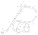
도 1 은 본 발명의 일 실시예에 따른 사이클론 집진장치가 마련되는 진공청소기를 나타내는 도면,
도 2 는 본 발명의 일 실시예에 따른 사이클론 집진장치를 나타내는 사시도,
도 3 은 본 발명의 일 실시예에 따른 사이클론 집진장치를 나타내는 분해 사시도,
도 4 는 도 2 의 A-A' 부분 단면도로서, 본 발명의 일 실시예에 따른 사이클론 집진장치의 단면도,
도 5 는 본 발명의 일 실시예에 따른 아웃렛부에 결합되는 그릴 어셈블리를 나타내는 도면,
도 6 은 본 발명의 일 실시예에 따른 그릴 어셈블리를 나타내는 저면 사시도,
도 7 은 본 발명의 일 실시예에 따른 그릴 어셈블리를 나타내는 분해 사시도,
도 8 은 본 발명의 일 실시예에 따른 그릴 어셈블리를 나타내는 정면도,
도 9 는 본 발명의 일 실시예에 따른 그릴 어셈블리의 회전체의 동작에 따른 기류 유동을 나타내는 도면,
도 10 은 도 3 의 B-B' 부분의 단면도로서, 본 발명의 일 실시예에 따른 그릴 어셈블리의 기류를 나타내는 도면,
도 11 은 본 발명의 다른 실시예에 따른 그릴 어셈블리를 나타내는 사시도,
도 12 는 도 11의 C-C' 부분의 단면도로서, 본 발명의 다른 실시예에 따른 그릴 어셈블리의 기류를 나타내는 도면이다.1 is a diagram showing a vacuum cleaner equipped with a cyclone dust collection device according to an embodiment of the present invention;
Figure 2 is a perspective view showing a cyclone dust collection device according to an embodiment of the present invention;
Figure 3 is an exploded perspective view showing a cyclone dust collection device according to an embodiment of the present invention;
Figure 4 is a partial cross-sectional view taken along line AA' of Figure 2, showing a cross-sectional view of a cyclone dust collector according to an embodiment of the present invention;
5 is a view showing a grill assembly coupled to an outlet portion according to an embodiment of the present invention;
6 is a bottom perspective view showing a grill assembly according to an embodiment of the present invention;
7 is an exploded perspective view showing a grill assembly according to an embodiment of the present invention;
8 is a front view showing a grill assembly according to an embodiment of the present invention;
9 is a diagram showing airflow according to the operation of the rotating body of the grill assembly according to an embodiment of the present invention;
Figure 10 is a cross-sectional view of portion BB' of Figure 3, showing the airflow of the grill assembly according to an embodiment of the present invention;
11 is a perspective view showing a grill assembly according to another embodiment of the present invention;
FIG. 12 is a cross-sectional view taken along line CC' of FIG. 11 and is a view showing an airflow of a grill assembly according to another embodiment of the present invention.
본 명세서에 기재된 실시예와 도면에 도시된 구성은 개시된 발명의 바람직한 일 예에 불과할 뿐이며, 본 출원의 출원시점에 있어서 본 명세서의 실시예와 도면을 대체할 수 있는 다양한 변형 예들이 있을 수 있다.The embodiments described in this specification and the configurations shown in the drawings are only preferred examples of the disclosed invention, and at the time of filing this application, there may be various modifications that can replace the embodiments and drawings in this specification.
또한, 본 명세서의 각 도면에서 제시된 동일한 참조번호 또는 부호는 실질적으로 동일한 기능을 수행하는 부품 또는 구성요소를 나타낸다.In addition, the same reference numbers or symbols shown in each drawing of this specification indicate parts or components that perform substantially the same function.
또한, 본 명세서에서 사용한 용어는 실시예를 설명하기 위해 사용된 것으로, 개시된 발명을 제한 및/또는 한정하려는 의도가 아니다. 단수의 표현은 문맥상 명백하게 다르게 뜻하지 않는 한, 복수의 표현을 포함한다. 본 명세서에서, "포함하다" 또는 "가지다" 등의 용어는 명세서상에 기재된 특징, 숫자, 단계, 동작, 구성요소, 부품 또는 이들을 조합한 것이 존재함을 지정하려는 것이지, 하나 또는 그 이상의 다른 특징들이나 숫자, 단계, 동작, 구성요소, 부품 또는 이들을 조합한 것들의 존재 또는 부가 가능성을 미리 배제하지 않는다.Additionally, the terms used herein are used to describe embodiments and are not intended to limit and/or limit the disclosed invention. Singular expressions include plural expressions unless the context clearly dictates otherwise. In this specification, terms such as “comprise” or “have” are intended to designate the presence of features, numbers, steps, operations, components, parts, or combinations thereof described in the specification, but are not intended to indicate the presence of one or more other features. The existence or addition of numbers, steps, operations, components, parts, or combinations thereof is not excluded in advance.
또한, 본 명세서에서 사용한 "제1", "제2" 등과 같이 서수를 포함하는 용어는 다양한 구성요소들을 설명하는데 사용될 수 있지만, 상기 구성요소들은 상기 용어들에 의해 한정되지는 않으며, 상기 용어들은 하나의 구성요소를 다른 구성요소로부터 구별하는 목적으로만 사용된다. 예를 들어, 본 발명의 권리 범위를 벗어나지 않으면서 제1 구성요소는 제2 구성요소로 명명될 수 있고, 유사하게 제2 구성요소도 제1 구성요소로 명명될 수 있다. "및/또는" 이라는 용어는 복수의 관련된 기재된 항목들의 조합 또는 복수의 관련된 기재된 항목들 중의 어느 항목을 포함한다.In addition, terms including ordinal numbers such as “first”, “second”, etc. used in this specification may be used to describe various components, but the components are not limited by the terms, and the terms It is used only for the purpose of distinguishing one component from another. For example, a first component may be named a second component without departing from the scope of the present invention, and similarly, the second component may also be named a first component. The term “and/or” includes any of a plurality of related stated items or a combination of a plurality of related stated items.
이하에서는 본 발명에 따른 실시예를 첨부된 도면을 참조하여 상세히 설명한다.Hereinafter, embodiments according to the present invention will be described in detail with reference to the attached drawings.
이하에서 사용되는 전면 및 전방은 도 1 에 도시된 진공청소기(1)를 기준으로 앞으로 보이는 전면 및 전방을 향하는 방향을 지칭하고, 후방은 진공청소기(1)의 후방을 향하는 방향을 지칭하도록 한다. 본 발명의 일 실시예에 따른 사이클론 집진장치는 캐니스터 타입(Canister Type)의 진공청소기에 적용된 것으로 설명하였으나, 업 라이트, 스틱, 로봇 청소기 등 모든 타입의 청소기에 적용 가능하고, 싱글 사이클론, 멀티 사이클론 등 모든 타입의 먼지통에 적용 가능하다.The terms front and front used hereinafter refer to the front and the direction facing forward relative to the
도 1 은 본 발명의 일 실시예에 따른 사이클론 집진장치가 마련되는 진공청소기를 나타내는 도면이다.1 is a diagram showing a vacuum cleaner equipped with a cyclone dust collection device according to an embodiment of the present invention.
도 1 에 도시된 바와 같이, 진공청소기(1)는 캐니스터 타입(Canister Type)의 진공 청소기일 수 있다. 진공청소기(1)는 본체(10), 본체(10)에 장착되는 사이클론 집진장치(100), 그리고 피청소면에 접촉하여 먼지 및 공기를 흡입하는 흡입부(21)를 포함할 수 있다.As shown in FIG. 1, the
사이클론 집진장치(100)는 선회 기류를 발생시켜 원심력에 의해 공기와 먼지를 분리할 수 있다.The
본체(10)는 흡입력을 생성하는 팬모터(미도시)를 포함한다. 본체(10)에서 생성되는 흡입력에 의해 흡입부(21)는 피청소면의 공기 및 먼지를 흡입할 수 있다.The
본체(10)와 흡입부(21) 사이에는 연장관(20), 사용자의 조작을 위한 핸들(30), 핸들(30)의 자유로운 이동을 위해 유연한 재질을 갖는 플렉시블 호스(23)가 마련될 수 있다. 핸들(30)에는 진공청소기(1)의 기능을 조작할 수 있는 조작부(31)가 마련될 수 있다.An
흡입부(21), 연장관(20), 핸들(30) 및 플렉시블 호스(23)는 모두 연통되도록 마련될 수 있다. 흡입부(21)를 통해 흡입된 공기와 먼지는 연장관(20), 핸들(30), 그리고 플렉시블 호스(23)를 순차적으로 통과해서 본체(10)로 이동될 수 있다.The
본체(10)에는 흡입된 공기를 사이클론 집진장치(100)로 안내하는 흡입포트(12)와 사이클론 집진장치(100)에서 정화된 공기가 배출되는 배출포트(13)가 마련될 수 있다. 배출포트(13)는 팬모터가 마련된 팬모터실(미도시)에 연통될 수 있다.The
본체(10)에는 사이클론 집진장치(100)를 장착할 수 있도록 장착부(미도시)가 마련될 수 있다. 사이클론 집진장치(100)는 장착부에 분리 가능하게 장착될 수 있다. 사이클론 집진장치(100)는 흡입부(21)를 통해 흡입된 공기에서 먼지를 분리하여 수거하고, 정화된 공기가 배출포트(13)를 통해 배출되도록 한다.The
도 2 는 본 발명의 일 실시예에 따른 사이클론 집진장치를 나타내는 사시도이고, 도 3 은 본 발명의 일 실시예에 따른 사이클론 집진장치를 나타내는 분해 사시도이며, 도 4 는 도 2 의 A-A' 부분 단면도로서, 본 발명의 일 실시예에 따른 사이클론 집진장치의 단면도이다.Figure 2 is a perspective view showing a cyclone dust collection device according to an embodiment of the present invention, Figure 3 is an exploded perspective view showing a cyclone dust collection device according to an embodiment of the present invention, and Figure 4 is a cross-sectional view of part A-A' of Figure 2. , This is a cross-sectional view of a cyclone dust collector according to an embodiment of the present invention.
도 2 내지 도 4 에 도시된 바와 같이, 사이클론 집진장치(100)는 먼지가 포함된 공기가 유입되는 입구(114)와 정화된 공기가 배출되는 출구(113)를 포함한다. 사이클론 집진장치(100)가 본체(10)에 장착될 때, 사이클론 집진장치(100)의 입구(114)는 본체(10)의 흡입포트(12)에 연결되고, 사이클론 집진장치(100)의 출구(113)는 본체(10)의 배출포트(13)에 연결될 수 있다.As shown in Figures 2 to 4, the
사이클론 집진장치(100)는 상면이 개방된 원통 형상의 사이클론 바디(110)와, 사이클론 바디(110)의 상부에 마련되는 커버(190)를 포함할 수 있다. 커버(190)는 사이클론 바디(110)와 힌지부재(180)에 의해 결합될 수 있다. 커버(190)는 사이클론 바디(110)에 분리 가능하게 연결될 수 있다. 사이클론 바디(110)에는 힌지축 수용부(181)가 마련되고, 커버(190)에는 힌지축 수용부(181)에 대응되도록 힌지축(182)이 마련될 수 있다.The
커버(190)의 일측에는 사용자가 커버(190)를 사이클론 바디(110)로부터 용이하게 분리하도록 하기 위한 손잡이(192)가 마련될 수 있다. 커버(190)의 손잡이(192)는 힌지축(182)에 대향되는 위치에 배치될 수 있다.A
한편, 사이클론 바디(110)와 커버(190)는 외부에서 사이클론 집진장치(100) 내부에 집진되는 먼지의 양을 확인할 수 있도록 투명한 재질로 마련될 수 있다. 사이클론 바디(110)와 커버(190)의 적어도 일부는 투명 또는 불투명 재질로 마련될 수 있다.Meanwhile, the
사이클론 바디(110)의 내부에는 선회기류를 형성하여 원심력에 의해 먼지를 분리하는 사이클론 챔버(140) 및 먼지를 수거하는 먼지 수거 챔버(150)가 마련될 수 있다. 사이클론 챔버(140) 및 먼지 수거 챔버(150)는 내벽(112)에 의해 구획될 수 있다. 사이클론 챔버(140)는 내벽(112)의 내측에 마련되고, 먼지 수거 챔버(150)는 내벽(112)과 외벽(111) 사이에 마련될 수 있다. 외벽(111)은 사이클론 바디(110)의 외관을 형성할 수 있다.Inside the
내벽(112)의 일측 상부에는 사이클론 챔버(140)에서 공기와 분리된 먼지가 먼지 수거 챔버(150)로 유동될 수 있도록 사이클론 챔버(140)와 먼지 수거 챔버(150)를 연통시키는 개구(115)가 마련될 수 있다. 원심력에 의해 공기에 비해 무거운 먼지는 외측으로 흩어지므로 개구(115)는 사이클론 챔버(140)의 외주측에 형성될 수 있다.At the top of one side of the
사이클론 챔버(140)는 선회기류를 형성하기 위해 원통 형상으로 형성되며, 선회기류를 안내하기 위해 사이클론 챔버(140)의 주위에는 나선 형태의 경사지게 형성되는 나선부(141)가 마련될 수 있다. 공기는 나선부(141)를 따라서 가이드되어 사이클론 챔버(140)의 주위를 빙글빙글 선회할 수 있게 된다.The
한편, 커버(190)의 저면에는 사이클론 챔버(140)의 선회기류에 의해 먼지 수거 챔버(150)로 이동하는 먼지를 안내하기 위한 가이드(193)가 형성될 수 있다. 가이드(193)는 커버(190)의 중심이 하측으로 함몰되어 외측으로 갈수록 경사를 가지도록 형성될 수 있다. 가이드(193)는 곡면(R)으로 형성될 수 있다. 커버(190)의 가이드(193)에 의해 안내되는 공기 및 먼지는 커버(190)의 외측으로 안내되어 먼지 수거 챔버(150)로 이동될 수 있다.Meanwhile, a
사용자는 커버(190)를 사이클론 바디(110)로부터 분리한 후, 먼지 수거 챔버(150)에 포집된 먼지를 비울 수 있다.The user may separate the
사이클론 바디(110)에는 커버(190)의 손잡이(192)와 결합되도록 대응되는 고정돌기(111a)가 형성될 수 있다.A
사이클론 집진장치(100)에는 사이클론 챔버(140)로 공기가 유입되는 인렛부(120,inlet part), 사이클론 챔버(140)에서 공기가 유출되는 아웃렛부(130,outlet psrt)가 마련될 수 있다. 인렛부(120)와 아웃렛부(130)는 사이클론 바디(110)의 저면에 형성될 수 있다. 아웃렛부(130)는 사이클론 바디(110)의 저면 중심에 위치되고, 인렛부(120)는 사이클론 바디(110)의 저면 중심에서 일측으로 편심되어 위치될 수 있다.The
인렛부(120)는 사이클론 집진장치(100)의 입구(114)에 연통되고, 아웃렛부(130)는 사이클론 집진장치(100)의 출구(113)에 연통되도록 마련될 수 있다.The
사이클론 집진장치(100)의 입구(114)를 통해 유입된 공기는 인렛부(120)를 통해 사이클론 챔버(140)로 진입할 수 있다. 사이클론 집진장치(100)의 내에서 먼지가 제거된 공기는 사이클론 챔버(140)의 아웃렛부(130)를 통해 외부로 유출될 수 있다.Air introduced through the
아웃렛부(130)는 내부에 소정의 공간을 갖는 원통형상을 포함할 수 있다. 아웃렛부(130)측에는 원심력에 의해 1차로 먼지가 제거된 정화 공기에서 먼지를 거르기 위한 그릴 어셈블리(200)가 마련될 수 있다. 그릴 어셈블리(200)는 유출관(131)에 마련될 수 있다. 유출관(131)은 아웃렛부(130)에 연통될 수 있다.The
그릴 어셈블리(200)는 그릴(220), 그릴(220)이 회전 가능하게 장착되는 회전체(230), 회전체(230)가 회전 가능하게 수용되는 케이스(210), 케이스(210)와 회전체(230) 사이에 마련되는 베어링(240)을 포함할 수 있다. 그릴(220)에 의해 이물질이 걸러진 공기는 아웃렛부(130)를 통해 사이클론 집진장치(100)로부터 유출될 수 있다. 그릴 어셈블리(200)의 상세한 구성에 대해서는 후술한다.The
이하, 본 발명의 일 실시예에 따른 진공청소기의 동작을 설명한다.Hereinafter, the operation of a vacuum cleaner according to an embodiment of the present invention will be described.
본체(10)의 팬모터가 구동되면, 팬모터의 흡입력에 의해 흡입부(21)를 통해 피청소면의 공기가 흡입될 수 있다. 흡입된 공기는 연장관(20), 핸들(30), 그리고 플렉시블 호스(23)를 순차적으로 통과하여 본체(10)에 장착된 사이클론 집진장치(100)로 유입될 수 있다.When the fan motor of the
사이클론 집진장치(100)로 유입된 공기는 인렛부(120)를 통해 사이클론 챔버(140)로 안내된다. 사이클론 챔버(140)로 안내된 공기는 사이클론 챔버(140) 내부의 나선부(141)에 의해 선회하면서 상승한다.The air introduced into the
공기보다 무게가 무서운 먼지는 원심력에 의해 반경 방향 외측으로 흩어지고, 사이클론 챔버(140)의 상측에 위치한 개구(115)를 통해 먼지 수거 챔버(150)로 유입되게 된다. 이때, 먼지는 커버(190)에 형성된 가이드(193)에 의해 안내될 수 있다. 먼지 수거 챔버(150)로 유입된 먼지는 중력에 의해 낙하하여 먼지 수거 챔버(150)에 포집될 수 있다.Dust, which weighs more than air, is scattered outward in the radial direction by centrifugal force and flows into the
사이클론 챔버(140) 내에서 원심력에 의해 1차로 먼지가 제거된 공기는 그릴 어셈블리(200)를 통과하면서 일정 크기 이상의 먼지가 2차로 걸러질 수 있다.The air from which dust is first removed by centrifugal force in the
그릴 어셈블리(200)를 통과한 공기는 유출관(131) 및 아웃렛부(130)를 통해 하측으로 안내될 수 잇다. 아웃렛부(130)를 통해 최종적으로 깨끗해진 공기는 출구(113)를 통해 사이클론 집진장치(100)를 빠져 나가고, 팬모터를 거쳐 본체(10)의 외부로 나가게 된다. 도시되지는 않았지만, 출구(113)에는 본체(10) 외측으로 나가는 공기중의 먼지를 거를 수 있는 필터가 더 마련될 수 있다.Air passing through the
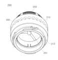
도 5 는 본 발명의 일 실시예에 따른 아웃렛부에 결합되는 그릴 어셈블리를 나타내는 도면이고, 도 6 은 본 발명의 일 실시예에 따른 그릴 어셈블리를 나타내는 저면 사시도이며, 도 7 은 본 발명의 일 실시예에 따른 그릴 어셈블리를 나타내는 분해 사시도이고, 도 8 은 본 발명의 일 실시예에 따른 그릴 어셈블리를 나타내는 정면도이며, 도 9 는 본 발명의 일 실시예에 따른 그릴 어셈블리의 회전체의 동작에 따른 기류 유동을 나타내는 도면이고, 도 10 은 도 3 의 B-B' 부분의 단면도로서, 본 발명의 일 실시예에 따른 그릴 어셈블리의 기류를 나타내는 도면이다.FIG. 5 is a diagram showing a grill assembly coupled to an outlet portion according to an embodiment of the present invention, FIG. 6 is a bottom perspective view showing a grill assembly according to an embodiment of the present invention, and FIG. 7 is an embodiment of the present invention. It is an exploded perspective view showing a grill assembly according to an example, Figure 8 is a front view showing the grill assembly according to an embodiment of the present invention, and Figure 9 is an airflow according to the operation of the rotating body of the grill assembly according to an embodiment of the present invention. It is a diagram showing the flow, and FIG. 10 is a cross-sectional view taken along the line B-B' of FIG. 3, and is a diagram showing the airflow of the grill assembly according to an embodiment of the present invention.
도 5 내지 도 10 에 도시된 바와 같이, 사이클론 집진장치(100)의 아웃렛부(130)에는 그릴 어셈블리(200)가 마련될 수 있다. 그릴 어셈블리(200)는 유출관(131)에 장착되어 공기 중의 일정 크기 이상의 먼지를 거를 수 있도록 마련된다. 그릴 어셈블리(200)에 의해 먼지가 걸러진 공기는 유출관(131) 및 아웃렛부(130)를 통해 안내되어 사이클론 집진장치(100)의 출구(113)로 안내된다.As shown in FIGS. 5 to 10 , a
그릴 어셈블리(200)는 팬모터의 흡입력에 의해 회전 가능하게 구비된다. 그릴 어셈블리(200)는 그릴(220)과, 그릴(220)이 장착되어 회전 가능하게 마련되는 회전체(230), 회전체(230)가 회전 가능하도록 수용되는 케이스(210), 케이스(210)와 회전체(230) 사이에 마련되는 베어링(240)을 포함할 수 있다.The
회전체(230)는 케이스(210) 내에 회전 가능하게 장착될 수 있다. 그릴(220)은 회전체(230)에 장착되어 회전체(230)와 함께 회전할 수 있다.The
케이스(210)는 유출관(131)에 장착될 수 있다. 케이스(210)는 유출관(131)의 형상에 대응되도록 형성될 수 있다. 본 발명의 실시예에서 유출관(131)은 원통형으로 구비되어 케이스(210)는 원통형으로 형성될 수 있다. 그릴 어셈블리(200)는 청소 또는 교체가 가능하도록 유출관(131)에서 분리 가능하게 장착될 수 있다.
케이스(210)는 제1케이스(211)와 제2케이스(212)를 포함할 수 있다. 제1케이스(211)는 유출관(131)에 결합할 수 있도록 형성된다.
제1케이스(211)는 하단에 마련된 결합돌기(213)에 의해 유출관(131)에 결합될 수 있다. 유출관(131)에는 결합돌기(213)에 대응되는 결합홈(133)이 형성될 수 있다. 본 발명의 실시예에서 케이스(210)는 제1케이스(211)에 형성된 결합돌기(213)와 유출관(131)의 결합홈(133)에 의해 결합되는 것을 예를 들어 도시하였으나, 본 발명의 사상은 이에 한정되지 않는다. 예를 들면 케이스는 유출관에 체결부재 또는 억지 끼움, 또는 나사 결합 등 분리 가능한 다양한 방법으로 결합될 수 있다.The
제1케이스(211)와 제2케이스(212)는 단차지게 형성될 수 있다. 제2케이스(212)는 제1케이스(211)의 상측으로 연장되어 형성될 수 있다. 제2케이스(212)는 회전체(230)가 회전 가능하게 수용되도록 회전체 수용부(215)가 내부에 형성될 수 있다.The
제2케이스(212)의 제2직경(D2)은 제1케이스(211)의 제1직경(D1) 보다 크게 마련될 수 있다.The second diameter D2 of the
제1케이스(211)는 유출관(131)의 내부로 삽입될 수 있다. 따라서, 제1케이스(211)의 제1직경(D1)은 유출관(131)의 내부 직경(D3) 과 동일하거나 작게 형성될 수도 있다.The
제1케이스(211)와 유출관(131) 사이에는 실링부재(250)가 마련될 수 있다. 실링부재(250)는 링 형상으로 형성될 수 있다. 실링부재(250)는 제1케이스(211)의 외주면에 끼워질 수 있다. 케이스(210)를 유출관(131)에 결합시키기 위해 제1케이스(211)의 외주면에 실링부재(250)가 결합된 상태로 결합될 수 있다. 실링부재(250)는 유출관(131)과 제1케이스(211) 사이에 빈틈이 발생하지 않도록 하고, 유출관(131)에 삽입된 제1케이스(211)가 유출관(131)으로부터 분리되는 것을 방지할 수 있도록 고정시킬 수 있다. 실링부재(250)는 고무 또는 실리콘 재질을 포함할 수 있다.A sealing
제2케이스(212)의 제2직경(D2)은 유출관(131)의 외주면 직경과 동일하거나 크게 형성될 수 있다. 제2케이스(212)의 내측에는 회전체(230)가 회전 가능하게 수용될 수 있는 회전체 수용부(215)가 마련될 수 있다.The second diameter D2 of the
제2케이스(212)에는 홀(300)이 형성된다. 제2케이스(212)의 홀(300)은 복수로 형성된다. 홀(300)은 제2케이스(212)의 둘레에 형성된다. 홀(300)은 제2케이스(212)의 둘레에 복수개가 일정 간격으로 이격되어 배치될 수 있다. 홀(300)은 제2케이스(212)의 내측 회전체 수용부(215)에 연통되도록 배치된다. 홀(300)은 제2케이스(212)의 외주면 둘레에 일정 간격 이격되어 배치될 수 있다. 복수의 홀(300)의 주변에는 외기가 잘 유입될 수 있도록 내측으로 함몰되는 홀가이드(301)가 형성될 수 있다. 홀(300)은 홀가이드(301)의 중심에 형성될 수 있다. 복수의 홀(300)을 통해 케이스(210) 외측의 공기가 케이스(210) 내측의 회전체 수용부(215)로 유입될 수 있다.A
제1케이스(211)에는 회전체(230)를 회전 가능하게 하는 베어링(240)이 장착되기 위한 베어링 장착부(214)가 마련된다. 베어링 장착부(214)는 제1케이스(211)의 내측에 마련된다.The
베어링(240)은 일측은 케이스(210)의 베어링 장착부(214)에 지지되고 타측은 회전체(230)에 지지될 수 있다.One side of the
회전체(230)는 케이스(210)와의 사이에 마련되는 베어링(240)에 의해 회전 가능하게 마련된다.The
회전체(230)는 그릴(220)이 결합되도록 마련되는 제1회전체(230a)와, 제1회전체(230a)로부터 하측으로 연장되는 제2회전체(230b)를 포함할 수 있다. 제1회전체(230a)와 제2회전체(230b)는 단차지게 형성될 수 잇다. 제1회전체(230a) 내측에는 제1팬(231)이 형성될 수 있다. 제1팬(231)은 회전체(230)의 회전 시 공기의 유동을 형성하도록 마련된다. 제1팬(231)은 회전체(230)의 중심으로부터 사방으로 연장 형성될 수 있다. 본 발명의 실시예에서 제1팬(231)은 세 개가 120 도 간격으로 형성되는 것을 예를 들어 도시하였으나, 본 발명의 사상은 이에 한정되지 않는다. 예를 들어 제1팬의 날개 개수는 3개 이하 또는 3개 이상으로 형성될 수 있다. 또 제1팬(231)은 바닥으로부터 수직하게 배치되는 것을 예를 들어 도시하였으나, 제1팬은 경사를 포함할 수 있다.The
제1팬(231)은 팬모터에 의해 흡입력이 발생하면 제1팬(231)에 의해 회전체(230)가 일 방향으로 회전할 수 있다. 제1팬(231)의 회전에 의한 공기의 유동 방향은 팬모터에 의한 흡입력에 의한 공기의 유동을 방해하지 않도록 마련될 수 있다. 제1팬(231)의 회전에 의한 공기는 그릴(220)과 아웃렛부(130) 사이에 형성되어 제1팬(231)측으로 유입된 공기가 아웃렛부(130)를 통해 배출되는 메인유로(200a)로 유동할 수 있다.When suction force is generated by the fan motor of the
제1회전체(230a)의 외측에는 제2팬(232)이 형성될 수 잇다. 제2팬(232)은 제1팬(231)에 의한 공기의 유동을 방해하도록 구비될 수 있다. 팬모터에 의한 흡입력이 발생하면, 제2팬(232)은 유출관(131)측으로부터 사이클론 챔버(140) 측으로 공기를 유동시킬 수 있다. 즉, 제2팬(232)은 팬모터의 흡입력에 의한 기류의 방향과 반대 방향의 기류를 발생시킬 수 있다. 제2팬(232)은 제1회전체(230a)의 외측면에 일정 간격 이격되어 복수개가 형성될 수 있다. 제2팬(232)은 회전체(230)의 측면에 구비되어 측면팬이라 할 수 있다.A
제2회전체(230b)에는 베어링(240)이 결합되기 위한 베어링 결합부(234)가 형성될 수 있다. 베어링 결합부(234)는 베어링(240)에 의해 회전체(230)가 회전될 수 있도록 마련된다.A bearing
제1회전체(230a)는 상단 테두리에 그릴(220)이 결합되도록 그릴 장착부(233)가 마련될 수 있다. 그릴 장착부(233)는 원형으로 형성되어 회전체(230)의 회전 시 그릴(220)이 분리되지 않도록 고정 및 지지한다.The first
그릴(220)은 반구 형상으로 형성될 수 있다. 그릴(220)은 다수의 홀(300)을 포함하여 마련된다. 그릴(220)의 하단 테두리는 원형으로 형성될 수 있다. 그릴(220)의 하단에는 그릴 장착부(233)에 결합되도록 대응되는 형상의 그릴 결합부(221)가 형성될 수 있다. 그릴(220)은 그릴 결합부(221)가 회전체(230)의 그릴 장착부(233)에 결합되어 고정된다. 회전체(230)에 결합된 그릴(220)은 회전체(230)와 함께 회전할 수 있다.The
한편, 그릴(220)이 회전체(230)와 함께 회전할 수 있도록 케이스(210)와 그릴(220) 사이에는 소정 간격의 갭(G)이 형성될 수 있다. 갭(G)은 그릴(220)이 장착된 회전체(230)와 케이스(210) 사이에 형성될 수 있다. 갭(G)은 그릴(220)이 결합되는 회전체(230)의 제1회전체(230a)의 상단 외주연과 제2케이스(212)의 내면(210a) 사이에 형성될 수 있다.Meanwhile, a gap G of a predetermined distance may be formed between the
팬모터에 흡입력이 발생되어 그릴(220)이 회전하면 그릴(220) 측 메인 유로(200a)로 공기가 유동하게 되고, 회전하는 그릴(220)과 케이스(210) 사이에 머리카락 등의 이물질이 낄 수 있게 된다.When suction force is generated in the fan motor and the
이러한 머리카락 등의 이물질은 그릴(220)의 회전을 방해할 수 있다. 이때, 제2케이스(212)에 형성된 복수의 홀(300)을 통해 유입되는 공기는 갭(G)을 통해 배출되는 먼지제거유로(200b)를 형성할 수 있다.Foreign substances such as hair may interfere with the rotation of the
먼지제거유로(200b)를 통해 배출되는 공기는 반구 형상의 그릴(220)에 붙은 먼지 또는 이물질을 원심력에 의해 떨어지게 할 수 있다.The air discharged through the
케이스(210) 외측에서 복수의 홀(300)을 통해 유입되는 공기가 먼지제거유로(200b)를 통해 갭(G)으로 배출되어 그릴(220)이 회전하지 못하게 되는 것을 방지할 수 있다.It is possible to prevent the
도 10 에 도시된 바와 같이, 그릴 어셈블리(200)의 동작을 설명한다.As shown in FIG. 10, the operation of the
그릴 어셈블리(200)는 그릴(220) 및 회전체(230)가 회전 가능하게 구비되어 원심력에 의해 그릴(220) 표면의 먼지 및 이물질 등이 떨어져 나갈 수 있도록 마련된다.The
팬모터에 의해 흡입력이 발생되면 회전체(230)와 그릴(220)은 일체로 회전할 수 있다. 사이클론 챔버(140)의 선회기류에 의해 먼지가 걸러진 공기는 그릴(220)을 통과하여 유출관(131) 측으로 유동하는 메인유로(200a)를 형성한다.When suction force is generated by the fan motor, the
이때, 메인유로(200a)는 그릴(220)로부터 유입되는 공기가 유출관(131) 측으로 배출되도록 상측에서 하측으로 형성될 수 있다.At this time, the
한편, 회전체(230)의 제2팬(232)과 케이스(210) 사이에서는 제2팬(232)에 의해 메인유로(200a)의 반대방향으로 기류가 형성될 수 있다. 그릴(220)이 장착된 회전체(230)의 제2팬(232)과 케이스(210) 사이의 갭(G)에서는 팬모터의 흡입력에 의한 공기 유동을 방해하도록 팬모터의 흡입력에 의한 기류의 방향과 반대 방향의 기류가 발생된다.Meanwhile, an airflow may be formed between the
케이스(210)에 형성된 복수의 홀(300)은 제2팬(232)과 케이스(210) 사이로 외기가 유입되도록 마련된다. 제2팬(232)과 케이스(210) 사이로 유입되는 외기는 먼지제거유로(200b)의 갭(G)을 통해 배출되어, 그릴(220)의 표면과 갭(G)에 달라붙은 먼지, 머리카락 등의 이물질을 제거할 수 있다.A plurality of
본 발명의 실시예에 따른 그릴(220)은 반구 형상으로 회전 가능하게 마련되어, 그릴(220)의 표면에 붙는 먼지 또는 머리카락 등이 그릴(220)의 회전 및 원심력에 의해 떨어져 나갈 수 있다. 이러한 반구 형상의 그릴(220)은 공기가 통과하는 면적을 넓힐 수 있고, 그에 따른 팬모터에 의한 흡입력이 저하되는 것을 방지할 수 있다.The
한편, 이렇게 떨어져 나간 먼지는 사이클론 챔버(140)의 선회 기류에 의해 회전하다가 먼지 수거 챔버(150)로 포집될 수 있다.Meanwhile, the fallen dust may be rotated by the swirling air current of the
따라서, 그릴(220)이 회전 가능하게 마련됨으로써 진공청소기(1)의 흡입력이 저하되는 것을 방지하고 청소 효율을 향상시킬 수 있다. 또한, 그릴(220)의 표면에 먼지가 달라붙지 않으므로 사이클론 집진장치(100) 내의 먼지를 제거하기 용이하다. 사용자는 사이클론 집진장치(100)를 본체(10)로부터 분리하여 커버(190)를 열고, 먼지 수거 챔버(150)에 포집된 먼지만 버리면 되므로, 사이클론 집진장치(100)를 쉽고 간편하게 청소할 수 있다.Accordingly, by providing the
또, 그릴(220)과 케이스(210) 사이의 갭(G)을 통해 먼지가 유입되지 않고, 그릴(220)과 케이스(210) 사이의 갭(G)에 먼지, 머리카락 등의 이물질이 끼는 것을 방지할 수 있다.In addition, it prevents dust from entering through the gap (G) between the
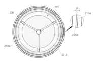
도 11 은 본 발명의 다른 실시예에 따른 그릴 어셈블리를 나타내는 사시도이고, 도 12 는 도 11의 C-C' 부분의 단면도로서, 본 발명의 다른 실시예에 따른 그릴 어셈블리의 기류를 나타내는 도면이다. 미도시된 도면 부호는 도 1 내지 도 10 을 참조한다.FIG. 11 is a perspective view showing a grill assembly according to another embodiment of the present invention, and FIG. 12 is a cross-sectional view taken along portion C-C' of FIG. 11, which is a view showing airflow of the grill assembly according to another embodiment of the present invention. Reference numbers not shown refer to FIGS. 1 to 10.
도 11 내지 도 12에 도시된 바와 같이, 그릴 어셈블리(200A)는 평면 형상의 그릴(220A)을 포함할 수 있다. 본 발명의 실시예에서 그릴(220A)은 반구 또는 평면 형상인 것을 예를 들어 도시하였으나, 본 발명의 사상은 이에 한정되지 않는다. 예를 들어 그릴은 반구형, 원뿔형, 원형, 판형, 실린더형 중 적어도 어느 하나를 포함할 수 있다.As shown in FIGS. 11 and 12 , the
그릴(220A)은 다수의 홀이 마련되는 원형의 판을 포함할 수 있다. 그릴(220A)은 회전체(230A)에 결합되어 회전 가능하게 마련된다. 회전체(230A)는 케이스(210A)의 내부에 회전 가능하게 수용될 수 있다. 회전체(230A)와 케이스(210A) 사이에는 베어링(240A)이 마련되어 회전체(230A)가 회전할 수 있도록 한다.The
회전체(230A)는 내부에 배치되는 제1팬(231A)과 외측면에 배치되는 제2팬(232A)을 포함할 수 있다.The
팬모터의 흡입력에 의해 회전체(230A)가 회전하면 제1팬(231A)측으로 유입되는 메인유로(200Aa)가 형성된다. 메인유로(200Aa)는 그릴(220A)을 통해 제1팬(231A) 측으로 유입되는 공기가 유출관(131)을 통해 배출되는 유로를 형성한다.When the
이때, 제2팬(232A)에 의해 발생하는 유동은 메인유로(200Aa)와 반대 방향의 유동이 발생한다. 케이스(210A)의 외측면에 형성되는 복수의 홀(300A)을 통해 유입되는 공기는 제2팬(232A)에 의해 메인유로(200Aa)의 반대 방향 즉, 케이스(210A)와 그릴(220A) 사이에 형성되는 갭(G)을 통해 배출되는 먼지 제거 유로(200Ab)를 형성할 수 있다.At this time, the flow generated by the second fan (232A) flows in the opposite direction to the main flow path (200Aa). The air flowing in through the plurality of
먼지 제거 유로(200Ab)는 케이스(210A)의 복수의 홀(300A)과 갭(G) 사이에 형성될 수 있다. 복수의 홀(300A)을 통해 유입되는 공기가 제2팬(232A)에 의해 그릴(220A)과 케이스(210A) 사이의 갭(G)을 통해 배출되어, 그릴(220A)과 케이스(210A) 사이로 먼지 및 머리카락이 끼거나 넘어가는 것을 방지할 수 있다.The dust removal passage 200Ab may be formed between the plurality of
상기한 구성에 의한 그릴 어셈블리(200A)의 구체적인 구조 및 동작은 상기 설명된 내용으로부터 충분히 예측 가능하므로 중복적인 설명은 생략한다.Since the specific structure and operation of the
이상에서는 특정의 실시예에 대하여 도시하고 설명하였다. 그러나, 상기한 실시예에만 한정되지 않으며, 발명이 속하는 기술분야에서 통상의 지식을 가진 자라면 이하의 청구범위에 기재된 발명의 기술적 사상의 요지를 벗어남이 없이 얼마든지 다양하게 변경 실시할 수 있을 것이다.In the above, specific embodiments are shown and described. However, it is not limited to the above-mentioned embodiments, and those skilled in the art can make various changes without departing from the gist of the technical idea of the invention as set forth in the claims below. .
1: 진공청소기10 : 본체
12 : 흡입포트13 : 배출포트
20 : 연장관21 : 흡입부
30 : 핸들100 : 사이클론 집진장치
110 : 사이클론 바디111 : 외벽
112 : 내벽113 : 출구
114 : 입구120 : 인렛부
130 : 아웃렛부131 : 유출관
140 : 사이클론 챔버141 : 나선부
150 : 먼지 수거 챔버190 : 커버
200, 200A : 그릴 어셈블리210 : 케이스
211 : 제1케이스212 : 제2케이스
220 : 그릴230 : 회전체
230a : 제1회전체230b : 제2회전체
231 : 제1팬232 : 제2팬
240 : 베어링250 : 실링부재
300 : 홀301 : 홀가이드 1: Vacuum cleaner 10: Main body
12: Suction port 13: Discharge port
20: extension tube 21: suction part
30: Handle 100: Cyclone dust collector
110: Cyclone body 111: External wall
112: inner wall 113: exit
114: entrance 120: inlet
130: Outlet portion 131: Outflow pipe
140: Cyclone chamber 141: Spiral portion
150: dust collection chamber 190: cover
200, 200A: grill assembly 210: case
211: 1st case 212: 2nd case
220: Grill 230: Rotating body
230a:
231: 1st fan 232: 2nd fan
240: Bearing 250: Sealing member
300: Hole 301: Hole Guide
Claims (20)
Translated fromKorean상기 사이클론 집진장치는,
인렛부를 통해 유입된 공기를 선회시켜 먼지를 분리하고, 먼지가 분리된 공기가 유출되도록 마련되는 아웃렛부를 포함하는 사이클론 챔버;
상기 아웃렛부에 회전 가능하게 마련되는 그릴;
상기 그릴이 장착되며, 회전 가능하게 마련되는 제1팬과, 상기 제1팬의 유동 방향과 반대 방향의 유동을 발생시키도록 마련되는 제2팬을 포함하는 회전체; 및
상기 회전체가 회전 가능하게 수용되고, 상기 그릴과의 사이에 갭이 형성되는 케이스;를 포함하고,
상기 케이스는,
외측 둘레에 형성되는 복수의 홀을 포함하고,
상기 복수의 홀을 통해 유입되는 공기가 상기 갭을 통해 배출되도록 상기 복수의 홀과 상기 갭 사이에 형성되는 먼지제거유로;를 포함하는 진공청소기.In a vacuum cleaner including a cyclone dust collector,
The cyclone dust collector is,
a cyclone chamber that separates dust by rotating air introduced through the inlet portion and includes an outlet portion through which the dust-separated air flows out;
A grill rotatably provided at the outlet portion;
a rotating body on which the grill is mounted and including a first fan rotatably provided and a second fan provided to generate a flow in a direction opposite to the flow direction of the first fan; and
A case in which the rotating body is rotatably accommodated and a gap is formed between the rotating body and the grill,
In the above case,
It includes a plurality of holes formed around the outer circumference,
A vacuum cleaner comprising: a dust removal passage formed between the plurality of holes and the gap so that air flowing in through the plurality of holes is discharged through the gap.
상기 케이스와 상기 회전체 사이에 마련되는 베어링을 포함하는 진공청소기.According to paragraph 1,
A vacuum cleaner including a bearing provided between the case and the rotating body.
상기 케이스는,
상기 아웃렛부에 연결되는 제1케이스와,
상기 제1케이스로부터 연장되어, 상기 회전체가 회전 가능하게 수용되도록 마련되는 제2케이스를 포함하고,
상기 복수의 홀은 상기 제2케이스에 배치되는 진공청소기.According to paragraph 3,
In the above case,
A first case connected to the outlet unit,
A second case extends from the first case and is provided to rotatably accommodate the rotating body,
The plurality of holes are disposed in the second case.
상기 사이클론 챔버는,
상기 그릴과 상기 아웃렛부 사이에 형성되어, 상기 제1팬측으로 유입되는 공기가 배출되는 메인 유로를 포함하는 진공청소기.According to paragraph 1,
The cyclone chamber is,
A vacuum cleaner including a main flow path formed between the grill and the outlet portion through which air flowing into the first fan is discharged.
상기 메인 유로와 먼지제거유로는 서로 격리되는 진공청소기.According to clause 5,
A vacuum cleaner in which the main flow path and the dust removal flow path are isolated from each other.
상기 회전체는 흡입력에 의해 회전하는 진공청소기.According to paragraph 1,
A vacuum cleaner in which the rotating body rotates by suction force.
상기 그릴은,
반구형, 원뿔형, 원형, 판형, 실린더형 중 적으로 어느 하나를 포함하는 진공청소기.According to paragraph 1,
The grill is,
A vacuum cleaner having any one of hemispherical, conical, circular, plate, and cylindrical shapes.
상기 제2케이스는,
상기 베어링이 장착되도록 형성되는 베어링 장착부를 포함하는 진공청소기.According to paragraph 4,
In the second case,
A vacuum cleaner including a bearing mounting portion formed to mount the bearing.
상기 회전체는,
상기 그릴이 결합되는 제1회전체와,
상기 제1회전체로부터 연장되어, 그 외측에 상기 베어링이 마련되는 제2회전체를 포함하고,
상기 제2팬은 상기 제1회전체의 외측에 배치되는 진공청소기.According to paragraph 3,
The rotating body is,
A first rotating body to which the grill is coupled,
It extends from the first rotating body and includes a second rotating body on the outside of which the bearing is provided,
The second fan is a vacuum cleaner disposed outside the first rotating body.
상기 제2회전체는,
상기 베어링이 결합되도록 형성되는 베어링 결합부를 포함하는 진공청소기.According to clause 10,
The second rotating body is,
A vacuum cleaner including a bearing coupling portion formed to couple the bearing.
상기 사이클론 챔버는 개폐 가능하게 마련되는 커버를 포함하고,
상기 커버는,
공기를 선회시켜 분리되는 먼지를 가이드 하기 위한 가이드를 더 포함하는 진공청소기.According to paragraph 1,
The cyclone chamber includes a cover that can be opened and closed,
The cover is,
A vacuum cleaner further comprising a guide for guiding dust that is separated by swirling air.
상기 가이드는,
상기 커버의 중심이 가장자리 보다 함몰되어, 중심에서 외측으로 경사지게 형성되는 진공청소기.According to clause 12,
The guide is:
A vacuum cleaner in which the center of the cover is depressed more than the edges and is inclined outward from the center.
상기 사이클론 챔버는 상기 아웃렛부와 연결되는 유출관을 포함하고,
상기 케이스와 상기 유출관 사이를 실링하는 실링부재가 마련되는 진공청소기.According to paragraph 1,
The cyclone chamber includes an outlet pipe connected to the outlet portion,
A vacuum cleaner provided with a sealing member that seals between the case and the outflow pipe.
상기 아웃렛부에 회전 가능하게 마련되는 그릴;
상기 그릴이 장착되며, 회전 가능하게 마련되는 제1팬과, 상기 제1팬의 유동 방향과 반대 방향의 유동을 발생시키도록 마련되는 제2팬을 포함하는 회전체;
상기 그릴과 상기 아웃렛부 사이에 형성되어, 상기 제1팬측으로 유입되는 공기가 배출되는 메인 유로;
상기 회전체가 회전 가능하게 수용되고, 공기가 유입되도록 둘레에는 복수의 홀이 형성되는 케이스;
상기 그릴과 상기 케이스 사이에 마련되는 갭;
상기 케이스와 상기 회전체 사이에 마련되는 베어링; 및
상기 복수의 홀을 통해 유입되는 공기가 상기 갭을 통해 배출되도록 상기 복수의 홀과 상기 갭 사이에 형성되는 먼지제거유로로서, 상기 먼지제거유로는 상기 메인 유로와 서로 격리되는 먼지제거유로;를 포함하는 사이클론 집진장치.a cyclone chamber that separates dust by rotating air introduced through the inlet portion and includes an outlet portion through which the dust-separated air flows out;
A grill rotatably provided at the outlet portion;
a rotating body on which the grill is mounted and including a first fan rotatably provided and a second fan provided to generate a flow in a direction opposite to the flow direction of the first fan;
a main flow path formed between the grill and the outlet portion through which air flowing into the first fan is discharged;
a case in which the rotating body is rotatably accommodated and a plurality of holes are formed around the circumference to allow air to flow;
a gap provided between the grill and the case;
a bearing provided between the case and the rotating body; and
A dust removal passage formed between the plurality of holes and the gap so that air flowing in through the plurality of holes is discharged through the gap, wherein the dust removal passage is a dust removal passage isolated from the main passage. Cyclone dust collection device.
상기 케이스는,
상기 아웃렛부에 연결되는 제1케이스와,
상기 제1케이스로부터 연장되어, 상기 회전체가 회전 가능하게 수용되도록 마련되는 제2케이스를 포함하고,
상기 복수의 홀은 상기 제2케이스에 배치되는 사이클론 집진장치.According to clause 15,
In the above case,
A first case connected to the outlet unit,
A second case extends from the first case and is provided to rotatably accommodate the rotating body,
A cyclone dust collector wherein the plurality of holes are disposed in the second case.
상기 그릴은,
반구형, 원뿔형, 원형, 판형, 실린더형 중 적으로 어느 하나를 포함하는 사이클론 집진장치.According to clause 15,
The grill is,
A cyclone dust collector including any one of hemispherical, conical, circular, plate, and cylindrical shapes.
상기 회전체는,
상기 그릴이 결합되는 제1회전체와,
상기 제1회전체로부터 연장되어, 그 외측에 상기 베어링이 마련되는 제2회전체를 포함하고,
상기 제2팬은 상기 제1회전체의 외측에 배치되는 사이클론 집진장치.According to clause 16,
The rotating body is,
A first rotating body to which the grill is coupled,
It extends from the first rotating body and includes a second rotating body on the outside of which the bearing is provided,
The second fan is a cyclone dust collector disposed outside the first rotating body.
상기 사이클론 챔버는 상기 아웃렛부와 연결되는 유출관을 포함하고,
상기 케이스와 상기 유출관 사이를 실링하는 실링부재가 마련되는 사이클론 집진장치.According to clause 15,
The cyclone chamber includes an outlet pipe connected to the outlet portion,
A cyclone dust collector provided with a sealing member that seals between the case and the outflow pipe.
Priority Applications (4)
| Application Number | Priority Date | Filing Date | Title |
|---|---|---|---|
| KR1020160169879AKR102665028B1 (en) | 2016-12-13 | 2016-12-13 | Cyclone dust collector and vacuum cleaner having the same |
| EP17880560.2AEP3528682B1 (en) | 2016-12-13 | 2017-12-08 | Cyclone dust collector and vacuum cleaner having the same |
| PCT/KR2017/014382WO2018110911A1 (en) | 2016-12-13 | 2017-12-08 | Cyclone dust collector and vacuum cleaner having the same |
| US15/838,743US10537220B2 (en) | 2016-12-13 | 2017-12-12 | Cyclone dust collector and vacuum cleaner having the same |
Applications Claiming Priority (1)
| Application Number | Priority Date | Filing Date | Title |
|---|---|---|---|
| KR1020160169879AKR102665028B1 (en) | 2016-12-13 | 2016-12-13 | Cyclone dust collector and vacuum cleaner having the same |
Publications (2)
| Publication Number | Publication Date |
|---|---|
| KR20180068204A KR20180068204A (en) | 2018-06-21 |
| KR102665028B1true KR102665028B1 (en) | 2024-05-13 |
Family
ID=62488159
Family Applications (1)
| Application Number | Title | Priority Date | Filing Date |
|---|---|---|---|
| KR1020160169879AActiveKR102665028B1 (en) | 2016-12-13 | 2016-12-13 | Cyclone dust collector and vacuum cleaner having the same |
Country Status (4)
| Country | Link |
|---|---|
| US (1) | US10537220B2 (en) |
| EP (1) | EP3528682B1 (en) |
| KR (1) | KR102665028B1 (en) |
| WO (1) | WO2018110911A1 (en) |
Families Citing this family (7)
| Publication number | Priority date | Publication date | Assignee | Title |
|---|---|---|---|---|
| CN108436848B (en)* | 2017-02-16 | 2024-02-27 | 博世电动工具(中国)有限公司 | Air pre-cleaning assembly and electric tool with same |
| JP7005880B2 (en)* | 2017-06-21 | 2022-01-24 | バイオドライングテック エスピーエー | Accelerated cyclone separating solid particles |
| US10894228B2 (en)* | 2018-10-15 | 2021-01-19 | Digo Creative Enterprise Ltd. | Inflatable valve filter |
| CN111467884A (en)* | 2020-03-12 | 2020-07-31 | 江苏人和环保设备有限公司 | Front dust removal and collection system of cloth bag type air dust collector |
| CN112190174A (en)* | 2020-11-04 | 2021-01-08 | 苏州睿梵工业设计有限公司 | Hand-held vacuum cleaner |
| KR20220119980A (en)* | 2021-02-22 | 2022-08-30 | 엘지전자 주식회사 | Station for cleaner |
| KR20230043581A (en)* | 2021-09-24 | 2023-03-31 | 삼성전자주식회사 | Dust seperation device and cleaner having the same |
Citations (1)
| Publication number | Priority date | Publication date | Assignee | Title |
|---|---|---|---|---|
| KR101486860B1 (en)* | 2008-05-14 | 2015-01-30 | 삼성전자주식회사 | Cyclone dust collecting apparatus and vacuum cleaner having the same |
Family Cites Families (11)
| Publication number | Priority date | Publication date | Assignee | Title |
|---|---|---|---|---|
| KR100406638B1 (en)* | 2000-01-22 | 2003-11-22 | 삼성광주전자 주식회사 | Vacuum cleaner |
| KR100433414B1 (en)* | 2002-05-11 | 2004-05-31 | 삼성광주전자 주식회사 | Cyclone-type dust collect apparatus for vacuum cleaner |
| KR100437106B1 (en)* | 2002-05-31 | 2004-06-23 | 삼성광주전자 주식회사 | Cyclone-type dust collecting apparatus for vacuum cleaner |
| US7351269B2 (en)* | 2003-12-22 | 2008-04-01 | Lau Kwok Yau | Self cleaning filter and vacuum incorporating same |
| KR100767123B1 (en) | 2005-10-19 | 2007-10-17 | 삼성광주전자 주식회사 | Dust collector of vacuum cleaner |
| KR100783142B1 (en)* | 2007-03-12 | 2007-12-07 | 삼성광주전자 주식회사 | Dust collector of vacuum cleaner |
| JP4798637B2 (en) | 2008-10-20 | 2011-10-19 | シャープ株式会社 | Dust collector and vacuum cleaner |
| US9011564B2 (en)* | 2009-07-21 | 2015-04-21 | Koninklijke Philips N.V. | Unit for pumping air containing particles and separating the particles from the air |
| CN104042166B (en) | 2013-03-14 | 2017-04-12 | 东芝生活电器株式会社 | Electric Cleaner |
| KR102308501B1 (en)* | 2015-03-27 | 2021-10-06 | 삼성전자주식회사 | Cyclone dust collector and vacuum cleaner having the same |
| KR102516499B1 (en)* | 2015-12-30 | 2023-04-03 | 삼성전자주식회사 | Cyclone dust collector and vacuum cleaner having the same |
- 2016
- 2016-12-13KRKR1020160169879Apatent/KR102665028B1/enactiveActive
- 2017
- 2017-12-08EPEP17880560.2Apatent/EP3528682B1/enactiveActive
- 2017-12-08WOPCT/KR2017/014382patent/WO2018110911A1/ennot_activeCeased
- 2017-12-12USUS15/838,743patent/US10537220B2/enactiveActive
Patent Citations (1)
| Publication number | Priority date | Publication date | Assignee | Title |
|---|---|---|---|---|
| KR101486860B1 (en)* | 2008-05-14 | 2015-01-30 | 삼성전자주식회사 | Cyclone dust collecting apparatus and vacuum cleaner having the same |
Also Published As
| Publication number | Publication date |
|---|---|
| US20180160871A1 (en) | 2018-06-14 |
| EP3528682A1 (en) | 2019-08-28 |
| KR20180068204A (en) | 2018-06-21 |
| EP3528682A4 (en) | 2019-08-28 |
| US10537220B2 (en) | 2020-01-21 |
| EP3528682B1 (en) | 2022-06-08 |
| WO2018110911A1 (en) | 2018-06-21 |
Similar Documents
| Publication | Publication Date | Title |
|---|---|---|
| KR102665028B1 (en) | Cyclone dust collector and vacuum cleaner having the same | |
| KR102308501B1 (en) | Cyclone dust collector and vacuum cleaner having the same | |
| KR100437371B1 (en) | Cyclone dust-collecting apparatus for Vaccum Cleaner | |
| RU2325836C2 (en) | Dust control unit for vacuum-cleaner (options) | |
| US7645309B2 (en) | Dust collection unit and vacuum cleaner with the same | |
| EP2581019B1 (en) | Cyclonic separation apparatus | |
| KR102516499B1 (en) | Cyclone dust collector and vacuum cleaner having the same | |
| KR20070089457A (en) | Vacuum cleaner | |
| KR102246450B1 (en) | Cleaner | |
| KR102463056B1 (en) | Cyclone dust collector and vacuum cleaner having the same | |
| EP1676514A2 (en) | Vacuum cleaner | |
| KR102341743B1 (en) | Cyclone dust collector, vacuum cleaner having the cyclone dust collector and handy-stick type vacuum cleaner having the cyclone dust collector | |
| KR20060125956A (en) | Dust collection unit | |
| JP6918679B2 (en) | Vacuum cleaner | |
| KR200394919Y1 (en) | Dust collecting unit | |
| KR20060125955A (en) | Dust collection unit | |
| KR20050119737A (en) | A vacuum cleaner | |
| KR101196029B1 (en) | Dust collecting unit | |
| KR20050119739A (en) | A dust collector for vacuum cleaner | |
| KR100546624B1 (en) | Dust collector of vacuum cleaner | |
| KR20060125951A (en) | Dust collection unit | |
| KR200394918Y1 (en) | Dust collecting unit | |
| KR20070012988A (en) | Dust collection unit | |
| KR20050119741A (en) | A dust collector for vacuum cleaner | |
| KR20060125953A (en) | Dust collection unit |
Legal Events
| Date | Code | Title | Description |
|---|---|---|---|
| PA0109 | Patent application | Patent event code:PA01091R01D Comment text:Patent Application Patent event date:20161213 | |
| PG1501 | Laying open of application | ||
| A201 | Request for examination | ||
| PA0201 | Request for examination | Patent event code:PA02012R01D Patent event date:20211207 Comment text:Request for Examination of Application Patent event code:PA02011R01I Patent event date:20161213 Comment text:Patent Application | |
| E902 | Notification of reason for refusal | ||
| PE0902 | Notice of grounds for rejection | Comment text:Notification of reason for refusal Patent event date:20230731 Patent event code:PE09021S01D | |
| E701 | Decision to grant or registration of patent right | ||
| PE0701 | Decision of registration | Patent event code:PE07011S01D Comment text:Decision to Grant Registration Patent event date:20240226 | |
| GRNT | Written decision to grant | ||
| PR0701 | Registration of establishment | Comment text:Registration of Establishment Patent event date:20240507 Patent event code:PR07011E01D | |
| PR1002 | Payment of registration fee | Payment date:20240508 End annual number:3 Start annual number:1 | |
| PG1601 | Publication of registration |