KR102663292B1 - Display apparatus and automotive apparatus - Google Patents
Display apparatus and automotive apparatusDownload PDFInfo
- Publication number
- KR102663292B1 KR102663292B1KR1020180146672AKR20180146672AKR102663292B1KR 102663292 B1KR102663292 B1KR 102663292B1KR 1020180146672 AKR1020180146672 AKR 1020180146672AKR 20180146672 AKR20180146672 AKR 20180146672AKR 102663292 B1KR102663292 B1KR 102663292B1
- Authority
- KR
- South Korea
- Prior art keywords
- disposed
- area
- pad
- sound generating
- generating device
- Prior art date
- Legal status (The legal status is an assumption and is not a legal conclusion. Google has not performed a legal analysis and makes no representation as to the accuracy of the status listed.)
- Active
Links
Images


Classifications
- B—PERFORMING OPERATIONS; TRANSPORTING
- B60—VEHICLES IN GENERAL
- B60R—VEHICLES, VEHICLE FITTINGS, OR VEHICLE PARTS, NOT OTHERWISE PROVIDED FOR
- B60R11/00—Arrangements for holding or mounting articles, not otherwise provided for
- B60R11/02—Arrangements for holding or mounting articles, not otherwise provided for for radio sets, television sets, telephones, or the like; Arrangement of controls thereof
- B60R11/0229—Arrangements for holding or mounting articles, not otherwise provided for for radio sets, television sets, telephones, or the like; Arrangement of controls thereof for displays, e.g. cathodic tubes
- B60R11/0235—Arrangements for holding or mounting articles, not otherwise provided for for radio sets, television sets, telephones, or the like; Arrangement of controls thereof for displays, e.g. cathodic tubes of flat type, e.g. LCD
- H—ELECTRICITY
- H04—ELECTRIC COMMUNICATION TECHNIQUE
- H04R—LOUDSPEAKERS, MICROPHONES, GRAMOPHONE PICK-UPS OR LIKE ACOUSTIC ELECTROMECHANICAL TRANSDUCERS; DEAF-AID SETS; PUBLIC ADDRESS SYSTEMS
- H04R1/00—Details of transducers, loudspeakers or microphones
- H04R1/20—Arrangements for obtaining desired frequency or directional characteristics
- H04R1/32—Arrangements for obtaining desired frequency or directional characteristics for obtaining desired directional characteristic only
- H—ELECTRICITY
- H04—ELECTRIC COMMUNICATION TECHNIQUE
- H04R—LOUDSPEAKERS, MICROPHONES, GRAMOPHONE PICK-UPS OR LIKE ACOUSTIC ELECTROMECHANICAL TRANSDUCERS; DEAF-AID SETS; PUBLIC ADDRESS SYSTEMS
- H04R7/00—Diaphragms for electromechanical transducers; Cones
- H04R7/02—Diaphragms for electromechanical transducers; Cones characterised by the construction
- H04R7/04—Plane diaphragms
- H04R7/045—Plane diaphragms using the distributed mode principle, i.e. whereby the acoustic radiation is emanated from uniformly distributed free bending wave vibration induced in a stiff panel and not from pistonic motion
- G—PHYSICS
- G06—COMPUTING OR CALCULATING; COUNTING
- G06F—ELECTRIC DIGITAL DATA PROCESSING
- G06F3/00—Input arrangements for transferring data to be processed into a form capable of being handled by the computer; Output arrangements for transferring data from processing unit to output unit, e.g. interface arrangements
- G06F3/16—Sound input; Sound output
- B—PERFORMING OPERATIONS; TRANSPORTING
- B60—VEHICLES IN GENERAL
- B60R—VEHICLES, VEHICLE FITTINGS, OR VEHICLE PARTS, NOT OTHERWISE PROVIDED FOR
- B60R11/00—Arrangements for holding or mounting articles, not otherwise provided for
- B60R11/02—Arrangements for holding or mounting articles, not otherwise provided for for radio sets, television sets, telephones, or the like; Arrangement of controls thereof
- B60R11/0217—Arrangements for holding or mounting articles, not otherwise provided for for radio sets, television sets, telephones, or the like; Arrangement of controls thereof for loud-speakers
- G—PHYSICS
- G02—OPTICS
- G02F—OPTICAL DEVICES OR ARRANGEMENTS FOR THE CONTROL OF LIGHT BY MODIFICATION OF THE OPTICAL PROPERTIES OF THE MEDIA OF THE ELEMENTS INVOLVED THEREIN; NON-LINEAR OPTICS; FREQUENCY-CHANGING OF LIGHT; OPTICAL LOGIC ELEMENTS; OPTICAL ANALOGUE/DIGITAL CONVERTERS
- G02F1/00—Devices or arrangements for the control of the intensity, colour, phase, polarisation or direction of light arriving from an independent light source, e.g. switching, gating or modulating; Non-linear optics
- G02F1/01—Devices or arrangements for the control of the intensity, colour, phase, polarisation or direction of light arriving from an independent light source, e.g. switching, gating or modulating; Non-linear optics for the control of the intensity, phase, polarisation or colour
- G02F1/13—Devices or arrangements for the control of the intensity, colour, phase, polarisation or direction of light arriving from an independent light source, e.g. switching, gating or modulating; Non-linear optics for the control of the intensity, phase, polarisation or colour based on liquid crystals, e.g. single liquid crystal display cells
- G02F1/133—Constructional arrangements; Operation of liquid crystal cells; Circuit arrangements
- G02F1/1333—Constructional arrangements; Manufacturing methods
- G02F1/133308—Support structures for LCD panels, e.g. frames or bezels
- G—PHYSICS
- G06—COMPUTING OR CALCULATING; COUNTING
- G06F—ELECTRIC DIGITAL DATA PROCESSING
- G06F1/00—Details not covered by groups G06F3/00 - G06F13/00 and G06F21/00
- G06F1/16—Constructional details or arrangements
- G06F1/1601—Constructional details related to the housing of computer displays, e.g. of CRT monitors, of flat displays
- G06F1/1605—Multimedia displays, e.g. with integrated or attached speakers, cameras, microphones
- G—PHYSICS
- G06—COMPUTING OR CALCULATING; COUNTING
- G06F—ELECTRIC DIGITAL DATA PROCESSING
- G06F3/00—Input arrangements for transferring data to be processed into a form capable of being handled by the computer; Output arrangements for transferring data from processing unit to output unit, e.g. interface arrangements
- G06F3/16—Sound input; Sound output
- G06F3/165—Management of the audio stream, e.g. setting of volume, audio stream path
- G—PHYSICS
- G10—MUSICAL INSTRUMENTS; ACOUSTICS
- G10K—SOUND-PRODUCING DEVICES; METHODS OR DEVICES FOR PROTECTING AGAINST, OR FOR DAMPING, NOISE OR OTHER ACOUSTIC WAVES IN GENERAL; ACOUSTICS NOT OTHERWISE PROVIDED FOR
- G10K11/00—Methods or devices for transmitting, conducting or directing sound in general; Methods or devices for protecting against, or for damping, noise or other acoustic waves in general
- G10K11/002—Devices for damping, suppressing, obstructing or conducting sound in acoustic devices
- G—PHYSICS
- G10—MUSICAL INSTRUMENTS; ACOUSTICS
- G10K—SOUND-PRODUCING DEVICES; METHODS OR DEVICES FOR PROTECTING AGAINST, OR FOR DAMPING, NOISE OR OTHER ACOUSTIC WAVES IN GENERAL; ACOUSTICS NOT OTHERWISE PROVIDED FOR
- G10K11/00—Methods or devices for transmitting, conducting or directing sound in general; Methods or devices for protecting against, or for damping, noise or other acoustic waves in general
- G10K11/004—Mounting transducers, e.g. provided with mechanical moving or orienting device
- G—PHYSICS
- G10—MUSICAL INSTRUMENTS; ACOUSTICS
- G10K—SOUND-PRODUCING DEVICES; METHODS OR DEVICES FOR PROTECTING AGAINST, OR FOR DAMPING, NOISE OR OTHER ACOUSTIC WAVES IN GENERAL; ACOUSTICS NOT OTHERWISE PROVIDED FOR
- G10K9/00—Devices in which sound is produced by vibrating a diaphragm or analogous element, e.g. fog horns, vehicle hooters or buzzers
- G10K9/12—Devices in which sound is produced by vibrating a diaphragm or analogous element, e.g. fog horns, vehicle hooters or buzzers electrically operated
- G10K9/122—Devices in which sound is produced by vibrating a diaphragm or analogous element, e.g. fog horns, vehicle hooters or buzzers electrically operated using piezoelectric driving means
- G—PHYSICS
- G10—MUSICAL INSTRUMENTS; ACOUSTICS
- G10K—SOUND-PRODUCING DEVICES; METHODS OR DEVICES FOR PROTECTING AGAINST, OR FOR DAMPING, NOISE OR OTHER ACOUSTIC WAVES IN GENERAL; ACOUSTICS NOT OTHERWISE PROVIDED FOR
- G10K9/00—Devices in which sound is produced by vibrating a diaphragm or analogous element, e.g. fog horns, vehicle hooters or buzzers
- G10K9/12—Devices in which sound is produced by vibrating a diaphragm or analogous element, e.g. fog horns, vehicle hooters or buzzers electrically operated
- G10K9/13—Devices in which sound is produced by vibrating a diaphragm or analogous element, e.g. fog horns, vehicle hooters or buzzers electrically operated using electromagnetic driving means
- H—ELECTRICITY
- H04—ELECTRIC COMMUNICATION TECHNIQUE
- H04R—LOUDSPEAKERS, MICROPHONES, GRAMOPHONE PICK-UPS OR LIKE ACOUSTIC ELECTROMECHANICAL TRANSDUCERS; DEAF-AID SETS; PUBLIC ADDRESS SYSTEMS
- H04R1/00—Details of transducers, loudspeakers or microphones
- H04R1/20—Arrangements for obtaining desired frequency or directional characteristics
- H04R1/22—Arrangements for obtaining desired frequency or directional characteristics for obtaining desired frequency characteristic only
- H04R1/28—Transducer mountings or enclosures modified by provision of mechanical or acoustic impedances, e.g. resonator, damping means
- H04R1/2807—Enclosures comprising vibrating or resonating arrangements
- H04R1/2811—Enclosures comprising vibrating or resonating arrangements for loudspeaker transducers
- H—ELECTRICITY
- H04—ELECTRIC COMMUNICATION TECHNIQUE
- H04R—LOUDSPEAKERS, MICROPHONES, GRAMOPHONE PICK-UPS OR LIKE ACOUSTIC ELECTROMECHANICAL TRANSDUCERS; DEAF-AID SETS; PUBLIC ADDRESS SYSTEMS
- H04R7/00—Diaphragms for electromechanical transducers; Cones
- H04R7/02—Diaphragms for electromechanical transducers; Cones characterised by the construction
- H04R7/04—Plane diaphragms
- H—ELECTRICITY
- H04—ELECTRIC COMMUNICATION TECHNIQUE
- H04R—LOUDSPEAKERS, MICROPHONES, GRAMOPHONE PICK-UPS OR LIKE ACOUSTIC ELECTROMECHANICAL TRANSDUCERS; DEAF-AID SETS; PUBLIC ADDRESS SYSTEMS
- H04R9/00—Transducers of moving-coil, moving-strip, or moving-wire type
- H04R9/02—Details
- H04R9/025—Magnetic circuit
- H—ELECTRICITY
- H04—ELECTRIC COMMUNICATION TECHNIQUE
- H04R—LOUDSPEAKERS, MICROPHONES, GRAMOPHONE PICK-UPS OR LIKE ACOUSTIC ELECTROMECHANICAL TRANSDUCERS; DEAF-AID SETS; PUBLIC ADDRESS SYSTEMS
- H04R9/00—Transducers of moving-coil, moving-strip, or moving-wire type
- H04R9/02—Details
- H04R9/04—Construction, mounting, or centering of coil
- H04R9/041—Centering
- H04R9/043—Inner suspension or damper, e.g. spider
- H—ELECTRICITY
- H05—ELECTRIC TECHNIQUES NOT OTHERWISE PROVIDED FOR
- H05K—PRINTED CIRCUITS; CASINGS OR CONSTRUCTIONAL DETAILS OF ELECTRIC APPARATUS; MANUFACTURE OF ASSEMBLAGES OF ELECTRICAL COMPONENTS
- H05K5/00—Casings, cabinets or drawers for electric apparatus
- H05K5/02—Details
- H05K5/03—Covers
- H—ELECTRICITY
- H04—ELECTRIC COMMUNICATION TECHNIQUE
- H04R—LOUDSPEAKERS, MICROPHONES, GRAMOPHONE PICK-UPS OR LIKE ACOUSTIC ELECTROMECHANICAL TRANSDUCERS; DEAF-AID SETS; PUBLIC ADDRESS SYSTEMS
- H04R2440/00—Bending wave transducers covered by H04R, not provided for in its groups
- H—ELECTRICITY
- H04—ELECTRIC COMMUNICATION TECHNIQUE
- H04R—LOUDSPEAKERS, MICROPHONES, GRAMOPHONE PICK-UPS OR LIKE ACOUSTIC ELECTROMECHANICAL TRANSDUCERS; DEAF-AID SETS; PUBLIC ADDRESS SYSTEMS
- H04R2499/00—Aspects covered by H04R or H04S not otherwise provided for in their subgroups
- H04R2499/10—General applications
- H04R2499/13—Acoustic transducers and sound field adaptation in vehicles
- H—ELECTRICITY
- H04—ELECTRIC COMMUNICATION TECHNIQUE
- H04R—LOUDSPEAKERS, MICROPHONES, GRAMOPHONE PICK-UPS OR LIKE ACOUSTIC ELECTROMECHANICAL TRANSDUCERS; DEAF-AID SETS; PUBLIC ADDRESS SYSTEMS
- H04R2499/00—Aspects covered by H04R or H04S not otherwise provided for in their subgroups
- H04R2499/10—General applications
- H04R2499/15—Transducers incorporated in visual displaying devices, e.g. televisions, computer displays, laptops
Landscapes
- Engineering & Computer Science (AREA)
- Physics & Mathematics (AREA)
- Acoustics & Sound (AREA)
- Multimedia (AREA)
- Theoretical Computer Science (AREA)
- Signal Processing (AREA)
- General Engineering & Computer Science (AREA)
- General Physics & Mathematics (AREA)
- Health & Medical Sciences (AREA)
- Human Computer Interaction (AREA)
- Nonlinear Science (AREA)
- Mechanical Engineering (AREA)
- Otolaryngology (AREA)
- Computer Hardware Design (AREA)
- Audiology, Speech & Language Pathology (AREA)
- General Health & Medical Sciences (AREA)
- Optics & Photonics (AREA)
- Mathematical Physics (AREA)
- Chemical & Material Sciences (AREA)
- Crystallography & Structural Chemistry (AREA)
- Microelectronics & Electronic Packaging (AREA)
- Electromagnetism (AREA)
- Devices For Indicating Variable Information By Combining Individual Elements (AREA)
- Fittings On The Vehicle Exterior For Carrying Loads, And Devices For Holding Or Mounting Articles (AREA)
- Diaphragms For Electromechanical Transducers (AREA)
Abstract
Translated fromKoreanDescription
Translated fromKorean본 명세서는 표시장치 및 차량용 장치에 관한 것이다.This specification relates to display devices and vehicle devices.
최근 정보화 시대로 접어듦에 따라 전기적 정보신호를 시각적으로 표현하는 디스플레이(display) 분야가 급속도로 발전해 왔다. 이에 박형화, 경량화, 저소비전력화의 우수한 성능을 지닌 여러 가지 다양한 표시장치(Display Apparatus)가 개발되고 있다.Recently, as we have entered the information age, the display field, which visually expresses electrical information signals, has developed rapidly. Accordingly, a variety of display devices are being developed that are thinner, lighter, and have excellent performance with lower power consumption.
예를 들면, 표시장치는 액정표시장치, 전계방출 표시장치, 및 유기발광 표시장치장치 등으로 분류될 수 있다.For example, display devices can be classified into liquid crystal displays, field emission displays, and organic light emitting display devices.
이들 표시장치 중에, 액정표시장치는 박막 트랜지스터를 포함하는 어레이 기판과, 컬러필터 및/또는 블랙매트릭스 등을 구비한 상부기판과, 어레이 기판과 상부 기판 사이에 액정층을 포함하여 구성된다. 화소 영역에 있는 두 개의 전극 사이에 인가되는 전계에 따라 액정층의 배열 상태가 조절되고 배열 상태에 따라 광의 투과도가 조절되어 화상이 표시되는 장치이다.Among these display devices, the liquid crystal display device includes an array substrate including thin film transistors, an upper substrate including a color filter and/or a black matrix, and a liquid crystal layer between the array substrate and the upper substrate. This is a device in which the arrangement of the liquid crystal layer is adjusted according to the electric field applied between two electrodes in the pixel area, and the light transmittance is adjusted according to the arrangement to display an image.
그리고, 유기발광 표시장치는 자발광소자로서 저소비 전력, 응답속도가 빠르고 발광 효율, 휘도 및 시야각이 큰 장점이 있다.Additionally, the organic light emitting display device is a self-emitting device and has the advantages of low power consumption, fast response speed, high luminous efficiency, brightness, and viewing angle.
표시장치는 표시패널 상에 화상을 표시하며, 소리를 제공하기 위해서 일반적으로 별도의 스피커를 설치해야 한다. 표시장치에 스피커를 설치할 경우, 스피커에서 발생된 소리는 화상이 표시되는 표시패널의 전면이 아닌 표시패널의 후면 또는 표시패널의 아래쪽으로, 예를 들면 표시패널에 표시되는 화상을 시청하는 시청자 방향으로 진행되므로, 이는 시청자의 몰입을 방해하게 된다.A display device displays images on a display panel, and generally requires a separate speaker to be installed to provide sound. When installing a speaker on a display device, the sound generated from the speaker is directed not to the front of the display panel where the image is displayed, but to the back or bottom of the display panel, for example, toward the viewer watching the image displayed on the display panel. As it progresses, this hinders the viewer's immersion.
또한, 스피커에서 발생된 소리는 표시패널의 후면 또는 표시패널의 아래쪽으로 진행하므로, 벽 또는 바닥에서 반사되는 소리와의 간섭으로 인해서 음질이 떨어지게 된다.Additionally, since the sound generated from the speaker travels to the back of the display panel or below the display panel, sound quality deteriorates due to interference with sound reflected from the wall or floor.
또한, TV, 랩탑 컴퓨터, 또는 컴퓨터 모니터 등과 같은 세트장치에 스피커가 포함될 경우, 스피커가 공간을 차지하게 되므로 세트장치의 디자인 및 공간 배치에 제약이 따르는 문제가 발생한다.Additionally, when speakers are included in a set device such as a TV, laptop computer, or computer monitor, the speakers take up space, which causes limitations in the design and spatial arrangement of the set device.
이에 본 명세서의 발명자들은 위에서 언급한 문제점들을 인식하고, 표시패널의 전면에서 영상을 시청할 시 소리의 진행방향이 표시패널의 전면이 될 수 있으며, 소리의 음질이 향상될 수 있는 여러 실험을 하게 되었다. 여러 실험을 거쳐 소리의 진행방향이 표시패널의 전면으로 되도록 음향을 발생시킬 수 있으며, 소리의 음질을 향상시킬 수 있는 새로운 구조의 표시장치를 발명하였다.Accordingly, the inventors of the present specification recognized the above-mentioned problems and conducted several experiments to determine that when viewing an image from the front of the display panel, the direction of sound can be in the front of the display panel and the quality of the sound can be improved. . Through various experiments, a display device with a new structure was invented that can generate sound so that the direction of sound travels toward the front of the display panel and improve the quality of the sound.
본 명세서의 실시예에 따른 해결 과제는 소리의 진행방향이 표시패널의 전면으로 되도록 음향을 발생시킬 수 있는 음향발생장치를 포함하는 표시장치를 제공하는 것이다.The problem to be solved according to the embodiments of the present specification is to provide a display device including a sound generator capable of generating sound so that the direction of sound travels toward the front of the display panel.
본 명세서의 실시예에 따른 해결 과제는 음향이 향상될 수 있는 새로운 구조의 음향발생장치를 포함하는 표시장치를 제공하는 것이다.The problem to be solved according to the embodiments of the present specification is to provide a display device including a sound generating device of a new structure in which sound can be improved.
본 명세서의 실시예에 따른 해결 과제들은 이상에서 언급한 과제들로 제한되지 않으며, 언급되지 않은 또 다른 과제들은 아래의 기재로부터 당업자에게 명확하게 이해될 수 있을 것이다.The problems to be solved according to the embodiments of the present specification are not limited to the problems mentioned above, and other problems not mentioned will be clearly understood by those skilled in the art from the description below.
본 명세서의 실시예에 따른 표시장치는, 영상을 표시하는 표시패널, 표시패널을 지지하는 지지부재, 표시패널 내에 배치되며, 표시패널을 진동시켜 음향을 발생시키는 적어도 하나의 음향발생장치, 및 지지부재의 하측에 배치되며, 적어도 하나의 음향발생장치의 중앙에 대응되도록 배치되는 연결부재를 포함한다.A display device according to an embodiment of the present specification includes a display panel for displaying an image, a support member for supporting the display panel, at least one sound generator disposed within the display panel and generating sound by vibrating the display panel, and a support. It is disposed on the lower side of the member and includes a connecting member disposed to correspond to the center of at least one sound generating device.
본 명세서의 실시예에 따른 표시장치는, 영상을 표시하며, 제1 영역, 제2 영역, 및 제3 영역을 포함하는 표시패널, 표시패널을 지지하는 지지부재, 표시패널 내에 배치되며, 제1 영역, 제2 영역, 및 제3 영역 중 적어도 하나의 영역에 배치되는 적어도 하나의 음향발생장치, 지지부재와 적어도 하나의 음향발생장치 사이에 배치되는 연결부재, 표시패널과 지지부재 사이에 배치되며, 제1 변과 제1 변과 수직인 제2 변을 포함하는 제1 파티션, 제1 영역과 제3 영역 사이에 배치되는 제2 파티션, 및 제2 영역과 제3 영역 사이에 배치되는 제3 파티션을 포함한다.A display device according to an embodiment of the present specification displays an image, includes a display panel including a first region, a second region, and a third region, a support member supporting the display panel, and is disposed within the display panel, and includes a first region, a second region, and a third region. At least one sound generating device disposed in at least one of the region, the second region, and the third region, a connecting member disposed between the support member and the at least one sound generating device, and disposed between the display panel and the support member; , a first partition including a first side and a second side perpendicular to the first side, a second partition disposed between the first area and the third area, and a third partition disposed between the second area and the third area. Contains partitions.
본 명세서의 실시예에 따른 차량용 장치는 차량 본체, 및 차량 본체에 배치되는 표시장치 또는 음향발생장치를 포함한다.A vehicle device according to an embodiment of the present specification includes a vehicle body, and a display device or sound generating device disposed on the vehicle body.
기타 실시예의 구체적인 사항들은 상세한 설명 및 도면들에 포함되어 있다.Specific details of other embodiments are included in the detailed description and drawings.
본 명세서의 실시예에 따른 표시장치는 표시패널을 진동시켜 음향을 발생시키는 음향발생장치를 구성함으로써, 표시장치의 소리의 진행방향이 표시패널의 전면으로 되도록 음향을 발생시킬 수 있다. 따라서, 표시장치의 영상을 시청하는 시청자의 몰입감을 향상시킬 수 있다.The display device according to an embodiment of the present specification is configured as a sound generating device that generates sound by vibrating the display panel, so that the sound of the display device can be generated so that the direction of sound travels toward the front of the display panel. Accordingly, the sense of immersion of the viewer watching the video on the display device can be improved.
본 명세서의 실시예에 따른 표시장치는 표시패널 내에 음향발생장치를 구성함으로써, 슬림화가 가능할 수 있으며, 음향이 향상될 수 있는 음향발생장치를 구현할 수 있다. 따라서, 본 명세서의 실시예에 따른 표시장치 또는 음향발생장치를 차량용 장치에 구현할 수 있는 장점이 있다.The display device according to an embodiment of the present specification can be slimmed by configuring a sound generating device within the display panel, and a sound generating device that can improve sound can be implemented. Therefore, there is an advantage that the display device or sound generating device according to the embodiments of the present specification can be implemented in a vehicle device.
본 명세서의 효과는 이상에서 언급한 효과에 제한되지 않으며, 언급되지 않은 또 다른 효과는 아래의 기재로부터 당업자에게 명확하게 이해될 수 있을 것이다.The effects of the present specification are not limited to the effects mentioned above, and other effects not mentioned will be clearly understood by those skilled in the art from the description below.
이상에서 해결하고자 하는 과제, 과제 해결 수단, 효과에 기재한 발명의 내용이 청구항의 필수적인 특징을 특정하는 것은 아니므로, 청구항의 권리 범위는 발명의 내용에 기재된 사항에 의하여 제한되지 않는다.Since the content of the invention described in the problem to be solved, the means for solving the problem, and the effect described above do not specify the essential features of the claim, the scope of the claim is not limited by the matters described in the content of the invention.
도 1a는 본 명세서의 실시예에 따른 음향발생장치를 포함하는 표시장치를 나타내는 도면이다.
도 1b는 도 1a의 절단선 I-I'을 따라 자른 단면도이다.
도 2a 및 도 2b는 본 명세서의 실시예에 따른 음향발생장치의 단면도이다.
도 3a 및 도 3b는 본 명세서의 실시예의 제1 구조에 따른 음향발생장치의 음향을 발생시키는 내용을 설명하는 도면이다.
도 4a 및 도 4b는 본 명세서의 실시예의 제2 구조에 따른 음향발생장치의 음향을 발생시키는 내용을 설명하는 도면이다.
도 5는 본 명세서의 실시예에 따른 음향발생장치와 지지부재와의 결합구조를 도시한 도면이다.
도 6은 본 명세서의 실시예에 따른 음향발생장치를 포함하는 표시장치를 나타내는 도면이다.
도 7은 본 명세서의 실시예에 따른 음향발생장치를 포함하는 표시장치를 나타내는 도면이다.
도 8a 및 도 8b는 본 명세서의 다른 실시예에 따른 음향발생장치를 포함하는 표시장치를 나타내는 도면이다.
도 8c 및 도 8d는 본 명세서의 다른 실시예에 따른 음향발생장치를 도시한 도면이다.
도 9a 내지 도 9d는 본 명세서의 다른 실시예에 따른 음향발생장치를 도시한 도면이다.
도 10a 및 도 10b는 본 명세서의 실시예에 따른 음향발생장치를 포함하는 표시장치를 나타내는 도면이다.
도 11a 내지 도 11d는 본 명세서의 실시예에 따른 음향발생장치와 파티션의 실시예를 도시한 도면이다.
도 12a 내지 도 12d는 본 명세서의 실시예에 따른 음향발생장치와 파티션의 실시예를 도시한 도면이다.
도 13a 및 도 13b는 본 명세서의 실시예에 따른 음향발생장치와 파티션의 실시예를 도시한 도면이다.
도 14a 및 도 14b는 본 명세서의 실시예에 따른 음향발생장치와 파티션의 실시예를 도시한 도면이다.
도 15a 및 도 15b는 본 명세서의 실시예에 따른 음향발생장치와 파티션의 실시예를 도시한 도면이다.
도 16a 및 도 16b는 본 명세서의 실시예에 따른 음향발생장치와 파티션의 실시예를 도시한 도면이다.
도 17a 내지 도 17d는 본 명세서의 실시예에 따른 음향발생장치와 파티션의 실시예를 도시한 도면이다.
도 18a 내지 도 18d는 본 명세서의 실시예에 따른 음향발생장치와 파티션의 실시예를 도시한 도면이다.
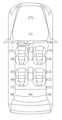
도 19는 본 명세서의 실시예에 따른 차량용 장치를 도시한 도면이다.FIG. 1A is a diagram illustrating a display device including a sound generating device according to an embodiment of the present specification.
FIG. 1B is a cross-sectional view taken along line II' of FIG. 1A.
2A and 2B are cross-sectional views of a sound generating device according to an embodiment of the present specification.
3A and 3B are diagrams illustrating the content of generating sound by the sound generating device according to the first structure of the embodiment of the present specification.
4A and 4B are diagrams illustrating the content of generating sound by the sound generating device according to the second structure of the embodiment of the present specification.
Figure 5 is a diagram showing a coupling structure between a sound generating device and a support member according to an embodiment of the present specification.
Figure 6 is a diagram showing a display device including a sound generating device according to an embodiment of the present specification.
Figure 7 is a diagram showing a display device including a sound generating device according to an embodiment of the present specification.
8A and 8B are diagrams showing a display device including a sound generating device according to another embodiment of the present specification.
Figures 8c and 8d are diagrams showing a sound generating device according to another embodiment of the present specification.
9A to 9D are diagrams showing a sound generating device according to another embodiment of the present specification.
10A and 10B are diagrams showing a display device including a sound generating device according to an embodiment of the present specification.
11A to 11D are diagrams showing examples of a sound generating device and a partition according to an embodiment of the present specification.
FIGS. 12A to 12D are diagrams illustrating examples of a sound generating device and a partition according to an embodiment of the present specification.
Figures 13a and 13b are diagrams showing an example of a sound generating device and a partition according to an embodiment of the present specification.
Figures 14a and 14b are diagrams showing an example of a sound generating device and a partition according to an embodiment of the present specification.
Figures 15a and 15b are diagrams showing an example of a sound generating device and a partition according to an embodiment of the present specification.
Figures 16a and 16b are diagrams showing an example of a sound generating device and a partition according to an embodiment of the present specification.
Figures 17a to 17d are diagrams illustrating examples of a sound generating device and a partition according to an embodiment of the present specification.
Figures 18A to 18D are diagrams illustrating examples of a sound generating device and a partition according to an embodiment of the present specification.
Figure 19 is a diagram showing a vehicle device according to an embodiment of the present specification.
본 명세서의 이점 및 특징, 그리고 그것들을 달성하는 방법은 첨부되는 도면과 함께 상세하게 후술되어 있는 실시예들을 참조하면 명확해질 것이다. 그러나, 본 명세서는 이하에서 개시되는 실시예들에 한정되는 것이 아니라 서로 다른 다양한 형태로 구현될 것이며, 단지 본 실시예들은 본 명세서의 개시가 완전하도록 하며, 본 명세서가 속하는 기술 분야에서 통상의 지식을 가진 자에게 발명의 범주를 완전하게 알려주기 위해 제공되는 것이며, 본 명세서는 청구항의 범주에 의해 정의될 뿐이다.The advantages and features of the present specification and methods for achieving them will become clear by referring to the embodiments described in detail below along with the accompanying drawings. However, the present specification is not limited to the embodiments disclosed below and will be implemented in various different forms, but the present embodiments only serve to ensure that the disclosure of the present specification is complete, and are common knowledge in the technical field to which the present specification pertains. It is provided to fully inform those who have the scope of the invention, and this specification is only defined by the scope of the claims.
본 명세서의 실시예를 설명하기 위한 도면에 개시된 형상, 크기, 비율, 각도, 개수 등은 예시적인 것이므로 본 명세서가 도시된 사항에 한정되는 것은 아니다. 명세서 전체에 걸쳐 동일 참조 부호는 동일 구성 요소를 지칭한다. 또한, 본 명세서를 설명함에 있어서, 관련된 공지 기술에 대한 구체적인 설명이 본 명세서의 요지를 불필요하게 흐릴 수 있다고 판단되는 경우 그 상세한 설명은 생략한다. 본 명세서 상에서 언급한 '포함한다', '갖는다', '이루어진다' 등이 사용되는 경우 '~만'이 사용되지 않는 이상 다른 부분이 추가될 수 있다. 구성 요소를 단수로 표현한 경우에 특별히 명시적인 기재 사항이 없는 한 복수를 포함하는 경우를 포함한다.The shape, size, ratio, angle, number, etc. disclosed in the drawings for explaining the embodiments of the present specification are illustrative, and the present specification is not limited to the matters shown. Like reference numerals refer to like elements throughout the specification. Additionally, in describing the present specification, if it is determined that a detailed description of related known technologies may unnecessarily obscure the gist of the present specification, the detailed description will be omitted. When 'includes', 'has', 'consists of', etc. mentioned in this specification are used, other parts may be added unless 'only' is used. In cases where a component is expressed in the singular, the plural is included unless specifically stated otherwise.
구성 요소를 해석함에 있어서, 오차 범위에 대한 별도의 명시적 기재가 없더라도 오차 범위를 포함하는 것으로 해석한다.When analyzing a component, the error range is interpreted to include the error range even if there is no separate explicit description of the error range.
위치 관계에 대한 설명일 경우, 예를 들어, "상에", "상부에", "하부에", "옆에" 등으로 두 부분의 위치 관계가 설명되는 경우, 예를 들면, "바로" 또는 "직접"이 사용되지 않는 이상 두 부분 사이에 하나 이상의 다른 부분이 위치할 수도 있다.In the case of a description of a positional relationship, for example, if the positional relationship of two parts is described as “on”, “at the top”, “at the bottom”, “next to”, etc., for example, “right away” Alternatively, there may be one or more other parts between the two parts, unless "directly" is used.
시간 관계에 대한 설명일 경우, "후에", 에 "이어서", "다음에", "전에" 등으로 시간적 선후 관계가 설명되는 경우, "바로" 또는 "직접"이 사용되지 않는 이상 연속적이지 않은 경우도 포함할 수 있다.In the case of a description of a temporal relationship, if a temporal relationship is described with “after”, “sequentially”, “next to”, “before”, etc., unless “immediately” or “directly” is used, it is not continuous. Cases may also be included.
제1, 제2 등이 다양한 구성요소들을 서술하기 위해서 사용되나, 이들 구성요소들은 이들 용어에 의해 제한되지 않는다. 이들 용어들은 단지 하나의 구성 요소를 다른 구성요소와 구별하기 위하여 사용하는 것이다. 따라서, 이하에서 언급되는 제1 구성요소는 본 명세서의 기술적 사상 내에서 제2 구성요소일 수도 있다.Although first, second, etc. are used to describe various components, these components are not limited by these terms. These terms are merely used to distinguish one component from another. Accordingly, the first component mentioned below may be the second component within the technical idea of the present specification.
본 명세서의 구성 요소를 설명하는 데 있어서, 제 1, 제 2, A, B, (a), (b) 등의 용어를 사용할 수 있다. 이러한 용어는 그 구성 요소를 다른 구성 요소와 구별하기 위한 것일 뿐, 그 용어에 의해 해당 구성 요소의 본질, 차례, 순서 또는 개수 등이 한정되지 않는다. 어떤 구성 요소가 다른 구성요소에 "연결", "결합" 또는 "접속"된다고 기재된 경우, 그 구성 요소는 그 다른 구성요소에 직접적으로 연결되거나 또는 접속될 수 있지만, 특별히 명시적인 기재 사항이 없는 간접적으로 연결되거나 또는 접속될 수 있는 각 구성 요소 사이에 다른 구성 요소가 "개재"될 수도 있다고 이해되어야 할 것이다.In describing the components of this specification, terms such as first, second, A, B, (a), and (b) may be used. These terms are only used to distinguish the component from other components, and the nature, sequence, order, or number of the components are not limited by the term. When a component is described as being “connected,” “coupled,” or “connected” to another component, that component may be directly connected or connected to that other component, but indirectly unless specifically stated otherwise. It should be understood that other components may be “interposed” between each component that can be connected or connected.
"적어도 하나"는 연관된 구성요소의 하나 이상의 모든 조합을 포함하는 것으로 이해되어야 할 것이다. 예를 들면, "제1, 제2, 및 제3 구성요소의 적어도 하나"의 의미는 제1, 제2, 또는 제3 구성요소뿐만 아니라, 제1, 제2, 및 제3 구성요소의 두 개 이상의 모든 구성요소의 조합을 포함한다고 할 수 있다.“At least one” should be understood to include any combination of one or more of the associated elements. For example, “at least one of the first, second, and third components” means not only the first, second, or third component, but also two of the first, second, and third components. It can be said to include a combination of all or more components.
본 명세서에서 "표시장치"는 표시패널과 표시패널을 구동하기 위한 구동부를 포함하는 액정 모듈(Liquid Crystal Module; LCM), 유기발광 표시모듈(OLED Module)과 같은 표시장치를 포함할 수 있다. 그리고, LCM, OLED 모듈 등을 포함하는 완제품(complete product 또는 final product)인 노트북 컴퓨터, 텔레비전, 컴퓨터 모니터, 차량용 또는 자동차용 장치(automotive apparatus) 또는 차량(vehicle)의 다른 형태 등을 포함하는 전장장치(equipment apparatus), 스마트폰 또는 전자패드 등의 모바일 전자장치(mobile electronic apparatus) 등과 같은 세트 전자 장치(set electronic apparatus) 또는 세트 장치(set device 또는 set apparatus)도 포함할 수 있다.In this specification, “display device” may include a display device such as a liquid crystal module (LCM) including a display panel and a driver for driving the display panel, and an organic light emitting display module (OLED module). And, electronic devices including laptop computers, televisions, computer monitors, automotive or automotive apparatus, or other types of vehicles, which are complete products or final products including LCM and OLED modules. It may also include a set electronic apparatus or set apparatus, such as an equipment apparatus, a mobile electronic apparatus such as a smartphone or an electronic pad.
따라서, 본 명세서에서의 표시장치는 LCM, OLED 모듈 등과 같은 디스플레이 장치 자체, 및 LCM, OLED 모듈 등을 포함하는 응용제품 또는 최종소비자용 장치인 세트 장치까지 포함할 수 있다.Accordingly, the display device in this specification may include the display device itself, such as an LCM, an OLED module, etc., and an application product including an LCM, an OLED module, etc., or a set device that is a device for end consumers.
그리고, 몇몇 예에서는, 표시패널과 구동부 등으로 구성되는 LCM, OLED 모듈을 "표시장치"로 표현하고, LCM, OLED 모듈을 포함하는 완제품으로서의 전자장치를 "세트장치"로 구별하여 표현할 수도 있다. 예를 들면, 표시장치는 액정(LCD) 또는 유기발광(OLED)의 표시패널과, 표시패널을 구동하기 위한 제어부인 소스 PCB를 포함할 수 있다. 세트장치는 소스 PCB에 전기적으로 연결되어 세트장치 전체를 구동하는 세트 제어부인 세트 PCB를 더 포함할 수 있다.Additionally, in some examples, the LCM and OLED modules composed of a display panel and a driver may be expressed as a “display device,” and the electronic device as a finished product including the LCM and OLED modules may be expressed as a “set device.” For example, a display device may include a liquid crystal display (LCD) or organic light emitting diode (OLED) display panel and a source PCB, which is a control unit for driving the display panel. The set device may further include a set PCB, which is a set control unit that is electrically connected to the source PCB and drives the entire set device.
본 실시예에 사용되는 표시패널은 액정표시패널, 유기전계발광(OLED: Organic Light Emitting Diode) 표시패널, 및 전계발광 표시패널(electroluminescent display panel) 등의 모든 형태의 표시패널이 사용될 수 있으며. 실시예가 이에 한정되는 것은 아니다. 예를 들면, 표시패널은 본 명세서의 실시예에 따른 음향발생장치에 의하여 진동됨으로써 음향을 발생할 수 있는 표시패널일 수 있다. 본 명세서의 실시예에 따른 표시장치에 적용되는 표시패널은 표시패널의 형태나 크기에 한정되지 않는다.The display panel used in this embodiment can be any type of display panel, such as a liquid crystal display panel, an organic light emitting diode (OLED) display panel, and an electroluminescent display panel. The examples are not limited to this. For example, the display panel may be a display panel that can generate sound by being vibrated by a sound generating device according to an embodiment of the present specification. The display panel applied to the display device according to the embodiments of the present specification is not limited to the shape or size of the display panel.
예를 들면, 표시패널이 액정표시패널인 경우에는, 다수의 게이트 라인과 데이터 라인, 및 게이트 라인과 데이터 라인의 교차 영역에 형성되는 픽셀(Pixel)을 포함할 수 있다. 그리고, 각 픽셀에서의 광투과도를 조절하기 위한 스위칭 소자인 박막 트랜지스터를 포함하는 어레이 기판과, 컬러필터 및/또는 블랙매트릭스 등을 구비한 상부기판과, 어레이 기판 및 상부기판 사이에 형성되는 액정층을 포함하여 구성될 수 있다.For example, when the display panel is a liquid crystal display panel, it may include a plurality of gate lines, data lines, and pixels formed in intersection areas of the gate lines and data lines. And, an array substrate including a thin film transistor, which is a switching element for controlling the light transmittance in each pixel, an upper substrate including a color filter and/or a black matrix, and a liquid crystal layer formed between the array substrate and the upper substrate. It may be configured to include.
표시패널이 유기전계발광(OLED) 표시패널인 경우에는, 다수의 게이트 라인과 데이터 라인, 및 게이트 라인과 데이터 라인의 교차 영역에 형성되는 픽셀(Pixel)을 포함할 수 있다. 그리고, 각 픽셀에 선택적으로 전압을 인가하기 위한 소자인 박막 트랜지스터를 포함하는 어레이 기판과, 어레이 기판 상의 유기 발광 소자(OLED)층, 및 유기 발광 소자층을 덮도록 어레이 기판 상에 배치되는 봉지 기판 또는 인캡슐레이션(Encapsulation) 기판 등을 포함하여 구성될 수 있다. 봉지 기판은 외부의 충격으로부터 박막 트랜지스터 및 유기 발광 소자층 등을 보호하고, 유기 발광 소자층으로 수분이나 산소가 침투하는 것을 방지할 수 있다. 그리고, 어레이 기판 상에 형성되는 층은 무기발광층(inorganic light emitting layer), 예를 들면 나노사이즈의 물질층(nano-sized material layer), 및 양자점(quantum dot) 발광층 등을 포함할 수 있다. 다른 예로는 마이크로 발광 다이오드를 포함할 수 있다.When the display panel is an organic electroluminescent (OLED) display panel, it may include a plurality of gate lines, data lines, and pixels formed in intersection areas of the gate lines and data lines. And, an array substrate including a thin film transistor, which is a device for selectively applying voltage to each pixel, an organic light emitting device (OLED) layer on the array substrate, and an encapsulation substrate disposed on the array substrate to cover the organic light emitting device layer. Alternatively, it may be configured to include an encapsulation substrate, etc. The encapsulation substrate protects the thin film transistor and the organic light emitting device layer from external shock and can prevent moisture or oxygen from penetrating into the organic light emitting device layer. Additionally, the layer formed on the array substrate may include an inorganic light emitting layer, for example, a nano-sized material layer, and a quantum dot light emitting layer. Other examples may include micro light emitting diodes.
표시패널은 표시패널에 부착되는 금속판(metal plate)과 같은 후면(backing)을 더 포함할 수 있다. 다른 구조, 예를 들면, 다른 물질로 이루어진 다른 구조가 포함될 수도 있다.The display panel may further include a backing such as a metal plate attached to the display panel. Other structures may also be included, for example, other structures made of other materials.
본 명세서의 여러 실시예들의 각각 특징들이 부분적으로 또는 전체적으로 서로 결합 또는 조합 가능하고, 기술적으로 다양한 연동 및 구동이 가능하며, 각 실시예들이 서로에 대하여 독립적으로 실시 가능할 수도 있고 연관 관계로 함께 실시할 수도 있다.Each feature of the various embodiments of the present specification can be combined or combined with each other, partially or entirely, and various technological interconnections and operations are possible, and each embodiment may be implemented independently of each other or together in a related relationship. It may be possible.
이하, 첨부된 도면 및 실시예를 통해 본 명세서의 실시예를 살펴보면 다음과 같다.Hereinafter, embodiments of the present specification will be examined through the attached drawings and examples.
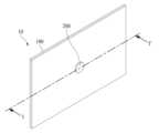
도 1a는 본 명세서의 실시예에 따른 음향발생장치를 포함하는 표시장치를 나타내는 도면이다.FIG. 1A is a diagram illustrating a display device including a sound generating device according to an embodiment of the present specification.
도 1a는 표시장치의 배면을 도시한 것이다. 도 1a를 참조하면, 표시장치(10)는 영상을 표시하는 표시패널(100)과 음향발생장치(200)를 포함할 수 있다. 음향발생장치(200)는 표시패널(100)을 진동시켜 음향을 발생시킬 수 있다. 음향발생장치(200)는 표시패널(100)의 배면에 배치될 수 있다. 표시패널(100)을 진동시켜 음향을 발생시키는 음향발생장치(200)를 포함할 수 있다.Figure 1A shows the back of the display device. Referring to FIG. 1A , the
표시패널(100)은 영상, 예를 들면 전자 영상(electronic image) 또는 디지털 영상(digital image)을 표시하는 것으로, 액정 디스플레이 패널(Liquid crystal Display Panel), 유기전계 발광(OLED: Organic Light Emitting Diode) 디스플레이 패널(Display Panel), 및 전계 발광 디스플레이 패널(Electroluminescent Display Panel) 등 모든 형태의 디스플레이 패널로 구현될 수 있다. 표시패널(100)은 음향발생장치(200)의 진동에 따라 진동하여 음향을 표시패널(100)의 전면 방향으로 출력할 수 있다.The
일 예에 따르면, 표시패널(100)은 애노드 전극, 캐소드 전극 및 유기 화합물층을 포함하는 픽셀 어레이층의 구조에 따라 탑 에미션(Top Emission) 방식, 바텀 에미션(Bottom Emission) 방식, 또는 듀얼 에미션(Dual Emission) 방식 등의 형태로 화상을 표시할 수 있다. 탑 에미션 방식은 픽셀 어레이층에서 발생된 가시광을 베이스 기판의 전방으로 방출시켜 영상을 표시할 수 있고, 바텀 에미션 방식은 픽셀 어레이층에서 발생된 가시광을 베이스 기판의 후방으로 방출시켜 영상을 표시할 수 있다.According to one example, the
그리고, 음향발생장치(200)는 표시패널(100)을 진동판으로 사용함으로써 음향을 발생시킬 수 있다. 음향발생장치는 엑츄에이터(actuator), 엑사이터(exciter), 또는 트랜스듀서(transducer)로 표현할 수도 있으며, 이 용어에 한정되지 않는다. 예를 들면, 음향발생장치(200)는 전기적 신호에 따라 음향을 출력하는 음향 기기일 수 있다.Additionally, the
도 1b는 도 1a의 절단선 I-I'을 따라 자른 단면도이다.FIG. 1B is a cross-sectional view taken along line II' of FIG. 1A.
도 1b를 참조하면, 표시장치는 음향발생장치(200) 및 지지부재(300)를 포함할 수 있다.Referring to FIG. 1B , the display device may include a
지지부재(supporting member; 300)는 표시패널(100)의 후면(rear surface) 또는 측면(side surface) 중 하나 이상을 지지할 수 있다. 그리고, 음향발생장치(200)는 지지부재(300)에 고정될 수 있다.The supporting
지지부재(300)는 예를 들면, 커버버텀(cover bottom)일 수 있다. 예를 들면, 표시패널(100)의 측면(lateral surface or side surface)을 둘러싸고, 커버버텀과 결합되고, 표시패널(100)을 지지하도록 표시패널(100)의 일측 가장자리를 수용하여 표시패널(100)을 지지하는 미들캐비넷(middle cabinet)을 포함할 수 있다. 예를 들어, 미들 캐비닛은 "┤"자 형태의 단면을 가질 수 있다. 지지부재(300)는 커버버텀, 또는 커버버텀 및 미들캐비넷을 포함할 수 있으나, 이 예의 구조에 한정하지 않는다. 지지부재(300)는 표시패널(100)의 후면 또는 측면을 지지할 수 있는 어떠한 구조 등을 포함할 수 있다.The
지지부재(300)는 표시패널(100)의 후면 또는 전체에 걸쳐서 형성되는 판상부재일 수 있다. 예를 들면, 지지부재(300)는 표시패널(100)의 후면 전체를 이격되게 덮을 수 있다. 지지부재(300)는 글라스 재질, 금속 재질, 또는 플라스틱 재질로 이루어진 평판 형태를 가질 수 있다. 예를 들면, 지지부재(300)의 가장자리 또는 날카로운 모서리 부분은 모따기 공정 또는 코너 라운딩 공정에 의해 사면 형태 또는 곡면 형태를 가질 수 있다. 일 예에 따르면, 글라스 재질의 지지부재(300)는 사파이어 글라스(Sapphire Glass)일 수 있다. 예를 들어, 금속 재질의 지지부재(300)는 하나 이상의 알루미늄, 알루미늄 합금, 마그네슘 합금, 및 철과 니켈의 합금 중 어느 하나의 재질로 이루어질 수 있다. 다른 예로는, 지지부재(300)는 금속 플레이트 및 글라스 플레이트보다 상대적으로 얇은 두께를 가지면서 표시패널(100)의 후면과 마주하는 글라스 플레이트의 적층 구조를 가질 수 있으며, 이 경우, 표시장치(10)의 후면은 금속 플레이트에 의해 거울면으로 사용될 수도 있다. 그러나, 이 예의 물질들이나 형상 등에 제한되는 것은 아니다.The
그리고, 지지부재(300)는 음향발생장치(200)가 삽입되는 관통홀을 포함할 수 있다. 예를 들면, 관통홀은 음향발생장치(200)가 삽입되기 위하여, 지지부재(300)의 두께 방향을 따라 지지부재(300)의 설정된 일부 영역에 원형 또는 다각 형태를 가지도록 천공될 수 있다.Additionally, the
그리고, 본 명세서에서 지지부재(300)는 커버버텀(Cover Bottom), 플레이트 버텀(Plate Bottom), 백커버(Back Cover), 베이스 프레임(Base Frame), 메탈 프레임(Metal Frame), 메탈 샤시(Metal Chassis), 샤시 베이스(Chassis Base), m-샤시 등 다른 표현으로 사용될 수 있다. 따라서, 표시패널(100)을 지지하는 지지체로서 표시장치의 후면에 배치되는 모든 형태의 프레임 또는 판상 구조물 등을 포함할 수 있다.And, in this specification, the
그리고, 접착부재(400)는 표시패널(100)과 지지부재(300)의 가장자리에 배치될 수 있다. 예를 들면, 접착부재(400)는 표시패널(100)의 배면 및 지지부재(300)의 상면 사이에 배치될 수 있다. 접착부재(400)는 표시패널(100)과 지지부재(300)를 접착시킬 수 있다. 그리고. 접착부재(400)는 양면 테이프(Double-sided Tape), 단면 테이프(Single-sided tape), 접착제, 및 본드 등일 수 있으며, 실시예에 한정되는 것은 아니다.Additionally, the
도 2a 및 도 2b는 본 명세서의 실시예에 따른 음향발생장치의 단면도이다.2A and 2B are cross-sectional views of a sound generating device according to an embodiment of the present specification.
음향발생장치는 마그네트가 코일의 외측에 배치되는 제1 구조와, 마그네트가 코일의 내측에 배치되는 제2 구조로 분류할 수 있다. 제1 구조는 다이나믹 타입(dynamic type) 또는 외자형(external magnetic type) 으로 표현할 수 있다. 그리고, 제2 구조는 마이크로 타입(micro type) 또는 내자형(internal magnetic type)으로 표현될 수 있다.Sound generating devices can be classified into a first structure in which a magnet is disposed on the outside of the coil, and a second structure in which the magnet is disposed on the inside of the coil. The first structure can be expressed as a dynamic type or external magnetic type. And, the second structure can be expressed as a micro type or internal magnetic type.
도 2a는 제1 구조를 도시한 것이고, 도 2b는 제2 구조를 도시한 것이다.Figure 2a shows the first structure, and Figure 2b shows the second structure.
도 2a를 참조하면, 음향발생장치(200)는 플레이트(210, 210'), 플레이트 상에 있는 마그네트(220), 플레이트 상에 있는 센터폴(230), 센터폴(230) 주위에 있는 보빈(250), 및 보빈(250) 외곽에 권취되어 있는 코일(260) 등을 포함할 수 있다.Referring to FIG. 2A, the
예를 들면, 제1 플레이트(210) 상에 마그네트(220)가 있으며, 마그네트(220) 상에 제2 플레이트(210')가 구비될 수 있다. 제1 플레이트(210)와 제2 플레이트(210')는 마그네트(220)를 지지하면서 음향발생장치(200)를 지지부재(300)에 고정시킬 수 있다. 따라서, 제1 플레이트(210)는 지지부재(300)의 지지홀에 고정될 수 있으며, 마그네트(220)는 제1 플레이트(210)와 제2 플레이트(210') 사이에서 고정 지지될 수 있다.For example, a
제1 플레이트(210) 및 제2 플레이트(210') 중 적어도 하나는 철(Fe)과 같은 물질로 이루질 수 있다. 제1 플레이트(210) 및 제2 플레이트(210')는 플레이트의 용어에 한정되는 것은 아니다. 예를 들면, 제1 플레이트(210) 및 제2 플레이트(210')는 요크 등 다른 용어로 표현될 수도 있다.At least one of the
마그네트(220)는 바륨 훼라이트 등의 소결(燒結) 자석을 이용할 수 있으며, 재질은 삼산화이철 (Fe2O3), 탄산바륨 (witherite)(BaCO3), 네오디뮴(Nd), 자력 성분이 개선된 스트론튬 훼라이트(Fe12O19Sr), 알루미늄(Al), 니켈(Ni), 코발트(Co) 의 합금 주조자석 등의 하나 이상을 포함할 수 있다. 다른 예로는, 네오디뮴 자석은 네오디뮴-철-붕소(Nd-Fe-B)일 수 있다. 그러나, 실시예는 이 예들에 한정되지 않는다.The
프레임(240)은 제1 플레이트(210)의 가장자리를 따라 제2 플레이트(210') 상에 배치될 수 있다. 센터폴(230)은 제1 플레이트(210)의 중앙영역에 센터폴(230)이 배치될 수 있다. 센터폴(230)과 제1 플레이트(210)는 일체로 형성될 수도 있다. 센터폴(230)은 폴피스(pole pieces)라고 할 수도 있다. 일 예에서는, 폴피스(pole pieces)가 센터폴(230) 상에 더 배치될 수도 있다. The
보빈(250)은 센터폴(230)의 주위를 감쌀 수 있다. 코일(260)은 보빈(250)의 아래의 일정 영역 주위, 예를 들면, 보빈(250)의 아래 영역에 권취될 수 있다. 예를 들면, 코일(260)은 보빈(250)의 아래의 외곽면에 권취되어 있으며, 이 코일(260)에 음향발생을 위한 전류 또는 보이스 신호가 인가될 수 있다.The
보빈(250)은 펄프 또는 종이를 가공한 재질, 알루미늄이나 마그네슘 또는 그 합금, 폴리프로필렌(polypropylene) 등의 합성 수지, 또는 폴리아미드(polyamide)계 섬유 등으로 형성된 환상(또는 원통) 구조물로 구현될 수 있으며, 이에 한정되는 것은 아니다. 보빈(250)과 코일(260)을 합하여 보이스 코일(voice coil)로 표현할 수도 있다.The
그리고, 댐퍼(270)는 보빈(250)의 상측 일부와 프레임(240) 사이에 배치될 수 있다. 댐퍼(damper)는 에지(edge) 등 다른 용어로 표현될 수도 있다.Additionally, the
도 2b는 마그네트가 코일의 내측에 배치되는 제2 구조를 도시한 도면이다.Figure 2b is a diagram showing a second structure in which a magnet is disposed inside a coil.
도 2b를 참조하면, 제2 구조의 음향발생표시장치(200')는 제1 플레이트(210) 상에 있는 마그네트(220), 마그네트(220) 상에 있는 센터폴(230), 마그네트(220)와 센터폴(230) 주위에 있는 보빈(250), 및 보빈(250) 외곽에 권취되어 있는 코일(260) 등을 포함할 수 있다.Referring to FIG. 2B, the sound generating display device 200' of the second structure includes a
예를 들면, 제1 플레이트(210)는 지지부재(300)의 지지홀에 고정될 수 있다. 마그네트(220)는 제1 플레이트(210) 상에 배치되며, 센터폴(230)은 마그네트(220) 상에 배치될 수 있다. 센터폴(230)은 폴피스(pole pieces)라고 할 수도 있다. 일 예에서는, 폴피스(pole pieces)가 센터폴(230) 상에 더 배치될 수도 있다.For example, the
보빈(250)은 마그네트(220)와 센터폴(230)을 둘러싸며, 코일(260)은 보빈(250) 외곽면에 권취될 수 있다.The
제2 플레이트(210')는 제1 플레이트(210)의 외곽 주변에 배치되며, 프레임(240)은 제2 플레이트(210')의 주변의 외측에 배치될 수 있다. 예를 들면, 댐퍼(270)는 프레임(240)과 보빈(250) 사이에 배치될 수 있다.The second plate 210' may be placed around the outside of the
마그네트가 외측에 배치되는 제1 구조에 비하여 내부 자석을 가지는 제2 구조는 누설자속이 작고 음향발생장치의 전체적인 크기를 작게 할 수 있는 장점이 있다.Compared to the first structure in which the magnet is disposed on the outside, the second structure with an internal magnet has the advantage of having a small magnetic leakage flux and reducing the overall size of the sound generating device.
본 명세서의 실시예에 의한 표시장치에 사용되는 음향발생장치는 도 2a 및 도 2b에 도시한 구조에 한정되는 것은 아니다. 표시패널을 진동시키는, 예를 들면, 표시패널을 직접 진동시켜 음향을 발생할 수 있는 다른 종류의 음향발생장치가 사용될 수도 있다.The sound generating device used in the display device according to the embodiment of the present specification is not limited to the structure shown in FIGS. 2A and 2B. Other types of sound generating devices that vibrate the display panel, for example, can generate sound by directly vibrating the display panel, may be used.
도 3a 및 도 3b는 본 명세서의 실시예의 제1 구조에 따른 음향발생장치의 음향을 발생시키는 내용을 설명하는 도면이다.3A and 3B are diagrams illustrating the content of generating sound by the sound generating device according to the first structure of the embodiment of the present specification.
도 3a는 전류가 인가된 상태를 나타낸다.Figure 3a shows a state in which current is applied.
마그네트(220)의 하면과 연결된 센터폴(230)이 N극이 되고, 마그네트(220)의 상면과 연결된 제2 플레이트(210')가 S극이 되어, 코일(260) 주변에 외부 자기장이 발생할 수 있다.The
이 상태에서 음향 발생용 전류가 코일(260)에 인가되면 코일(260) 주위에 인가 자기장이 형성되며, 인가 자기장과 외부 자기장에 의하여 보빈(250)을 상측으로 이동하는 힘이 발생된다. 예를 들면, 전류가 코일(260)에 인가되면 코일(260) 주위에 자기장이 형성되며, 마그네트(220)에 의하여 형성되는 외부 자기장이 있으므로, 플레밍의 왼손법칙에 따라 보빈(250) 전체가 센터폴(230)에 의하여 가이드되면서 상측으로 이동한다.In this state, when a current for sound generation is applied to the
따라서, 보빈(250)의 일면은 표시패널(100)의 후면에 접촉되며, 보빈은 코일(260)의 전류 인가 및 비인가에 따라 표시패널(100)을 상측(화살표로 표시)으로 진동시키게 되고, 표시패널(100)의 진동에 의하여 음파(또는 음향)가 발생하게 된다.Accordingly, one surface of the
이 상태에서 전류가 중지되거나 반대방향의 전류가 인가되면, 도 3b에 도시한 바와 같이, 도 3a에서 설명한 유사한 원리에 따라 보빈(250)을 하측으로 이동시키는 힘이 발생되고, 표시패널(100)이 하측(화살표로 표시)으로 진동한다.In this state, when the current is stopped or a current in the opposite direction is applied, as shown in FIG. 3B, a force is generated to move the
댐퍼(270)는 프레임(240)과, 보빈(250)의 상측 일부의 사이에 배치될 수 있다. 댐퍼(270)는 주름진 구조, 예를 들면 탄성을 가질 수 있으며, 댐퍼(270)는 보빈(250)의 상하 운동에 따라 수축 및 이완운동하면서 보빈(250)의 상하 진동을 조절할 수 있다. 예를 들면, 댐퍼(270)는 보빈(250)과 프레임(240)에 연결되어 있으며, 보빈(250)의 상하 진동은 댐퍼(270)의 복원력에 의해 조절될 수 있다. 예를 들면, 보빈(250)이 일정 높이 이상으로 진동하거나 일정 높이 이하로 진동할 경우 보빈(250)은 댐퍼(270)의 복원력에 의해 원위치로 원상 복귀할 수 있다.The
따라서, 코일(260)로의 전류 인가 방향과 크기에 따라서, 표시패널(100)이 상하방향으로 진동할 수 있으며, 이 진동에 의하여 음파가 발생될 수 있다.Therefore, depending on the direction and size of current application to the
도 4a 및 도 4b는 본 명세서의 실시예의 제2 구조에 따른 음향발생장치의 음향을 발생시키는 내용을 설명하는 도면이다.4A and 4B are diagrams illustrating the content of generating sound by a sound generating device according to the second structure of the embodiment of the present specification.
도 4a는 전류가 인가된 상태를 나타낸다.Figure 4a shows a state in which current is applied.
제2 플레이트(210)가 S극이 되고, 마그네트(220)의 상면과 연결된 센터폴(230)이 N극이 되어, 코일(260) 주변에 외부 자기장이 형성된다. N극과 S극은 서로 교환가능할 수 있으며, N극과 S극이 바뀔 경우에는 코일(260)의 권선방향을 수정하여 동일하게 동작시킬 수도 있다. 이 상태에서 음향 발생용 전류가 코일(260)에 인가되면 코일(260) 주위에 인가 자기장이 형성되며, 인가 자기장과 외부 자기장에 의하여 보빈(250)을 상측으로 이동하는 힘이 발생된다. 예를 들면, 코일(260)에 전류가 인가되면 코일(260) 주위에 자기장이 형성되며, 마그네트(220)에 의하여 형성되는 외부 자기장이 있으므로, 플레밍의 왼손법칙에 따라 보빈(250) 전체가 센터폴(230)에 의하여 가이드되면서 상측으로 이동한다.The
따라서, 보빈(250)의 일면은 표시패널(100)의 후면에 접촉되어 있으며, 코일(260)의 전류 인가 및 비인가 상태에 따라 표시패널(100)을 상측(화살표로 표시)으로 진동시키게 되고, 이 진동에 의하여 음파(또는 음향)가 발생하게 된다.Accordingly, one surface of the
이 상태에서 전류가 중지되거나 반대방향의 전류가 인가되면, 도 4b에 도시한 바와 같이, 도 4a에서 설명한 유사한 원리에 따라 보빈(250)을 하측으로 이동시키는 힘이 발생되고, 표시패널(100)이 하측(화살표로 표시)으로 진동한다.In this state, when the current is stopped or a current in the opposite direction is applied, as shown in FIG. 4B, a force is generated to move the
댐퍼(270)는 프레임(240)과, 보빈(250)의 상측 일부 사이에 배치될 수 있다. 댐퍼(270)는 탄성을 가지는 주름진 구조를 가질 수 있으며, 댐퍼(270)는 보빈(250)의 상하 운동에 따라 수축 및 이완운동하면서 보빈(250)의 상하 진동을 조절할 수 있다. 예를 들면, 댐퍼(270)는 보빈(250)과 프레임(240)에 연결되어 있으며, 보빈(250)의 상하 진동은 댐퍼(270)의 복원력에 의해 조절될 수 있다. 예를 들면, 보빈(250)이 일정 높이 이상으로 진동하거나 일정 높이 이하로 진동할 경우 보빈(250)은 댐퍼(270)의 복원력에 의해 원위치로 원상 복귀할 수 있다.The
따라서, 코일(260)로의 전류 인가 방향과 크기에 따라서, 표시패널(100)이 상하방향으로 진동할 수 있으며, 이 진동에 의하여 음파가 발생될 수 있다.Therefore, depending on the direction and size of current application to the
도 5는 본 명세서의 실시예에 따른 음향발생장치와 지지부재와의 결합구조를 도시한 도면이다.Figure 5 is a diagram showing a coupling structure between a sound generating device and a support member according to an embodiment of the present specification.
본 명세서의 실시예에서는 제1 구조 또는 제2 구조에 의한 음향발생장치 모두를 적용할 수 있으며, 이하에서는 제2 구조의 음향방생장치를 예로 들어 설명한다.In the embodiments of the present specification, both the first structure and the second structure sound generating device can be applied. Hereinafter, the sound generating device having the second structure will be described as an example.
도 5를 참조하면, 음향발생장치(200)는 확경부(614)를 포함할 수 있다. 확경부(614)는 제1 플레이트(210)와 일체로 형성될 수 있다. 음향발생장치(200)의 제1 플레이트(210)는 원통형 또는 실린더 형상이 아닐 수 있다. 제1 플레이트(210)의 일측은 제1 플레이트(210)의 나머지 부분의 직경보다 큰 돌출부를 가질 수 있다. 직경이 커진 돌출부 영역을 확경부(614)라고 표현할 수 있다. 확경부(614)는 환상을 가질 수 있다. 확경부(614) 중 일부에는 음향발생장치(200)의 고정을 위한 연장부(612)가 형성될 수 있다.Referring to Figure 5, the
연장부(612)에는 나사(screw; 320)와 너트(nut; 330)가 구성될 수 있다. 지지부재(300)에 고정된 너트(330)를 이용하여, 나사(320)에 의하여 음향발생장치(200)는 지지부재(300)에 결합할 수 있다. 너트(330)는 예를 들면, 셀프 클린칭 너트(self-clinching nut)일 수 있다. 셀프 클린칭 너트의 하나의 예는 팸너트(PEM® nut)일 수 있으며, 실시예가 이에 한정되는 것은 아니다. 이에 의해 음향발생장치(200)는 지지부재(300)에 있는 지지홀(310)에 수용될 수 있다.The
셀프 클린칭 너트(self-clinching nut)를 사용할 경우, 음향발생장치(200)에서 발생되는 진동이 너트(330)인 셀프 클린칭 너트에서 일부 흡수될 수 있으므로, 지지부재(300)로 전달되는 진동을 감소시킬 수 있다. 그리고, 표시패널(100)은 음향발생장치(200)의 보빈(250)에 부착될 수 있다.When using a self-clinching nut, the vibration generated by the
도 5에서 설명한 바와 같이, 음향발생장치는 지지부재의 지지홀을 통하여 표시패널에 결합할 수 있다. 따라서, 지지부재의 후면에는 지지홀이 필요하고, 지지홀에 의해 외부로부터의 이물질이 유입되는 문제점이 있었다. 그리고, 음향발생장치가 지지부재의 후면으로 노출되므로, 지지부재의 후면으로 노출되는 음향발생장치에 의하여 외관상 심미감을 저해하는 문제점이 있었다. 그리고, 지지부재의 후면으로 노출되는 음향발생장치의 손상을 방지하기 위해서 음향발생장치의 보호용 덮개가 필요하므로 보호용 덮개를 추가하는 공정이 필요하거나, 보호용 덮개에 의해 음향발생장치의 두께가 두꺼워지는 문제점이 있었다. 이에 본 명세서의 발명자들은 음향발생장치가 지지부재의 지지홀에 의해 지지부재와 결합되지 않고, 표시패널 내에 음향발생장치를 구성하기 위한 여러 실험을 하였다. 여러 실험을 통하여, 표시패널 내에 음향발생장치를 구성하기 위해서는 음향발생장치의 두께를 감소시켜야 함을 인식하였다. 음향발생장치가 두꺼울 경우에는 표시패널의 두께가 두꺼워지며, 표시패널의 화질 또는 화상에 영향을 줄 수 있으며, 외관상 심미감을 저해하는 문제점이 있음을 인식하였다. 따라서, 음향발생장치의 두께를 감소시키기 위해서는 음향발생장치에 포함된 구성요소들의 두께를 감소시켜야 한다. 예를 들면, 마그네트의 두께를 낮출 경우에는 자속밀도(magnetic flux density)가 줄어들므로 음압이 낮아지는 문제점이 생길 수 있다. 그리고, 보빈의 높이(또는 두께)를 낮출 경우에는 보빈에 감겨진 코일의 권폭이 줄어들므로, 음향발생장치의 자기력의 약화로 인해 음색의 명료도(articulation)가 낮아지거나 음압이 낮아지는 문제점이 생길 수 있다. 그리고, 전기적인 신호를 코일로 전달되는 배선은 댐퍼와의 간섭으로 인하여 음향발생장치에서 간섭음이 발생하는 문제점이 생길 수 있다. 이에 여러 실험을 통하여 음향발생장치의 면적을 넓게 하여 음향발생장치의 두께를 낮출 수 있으며, 음향에 영향을 주지 않는 새로운 구조의 음향발생장치를 발명하였다. 이에 대해서 도 6을 참조하여 설명한다.As described in FIG. 5, the sound generating device can be coupled to the display panel through the support hole of the support member. Therefore, a support hole is required at the rear of the support member, and there is a problem in that foreign substances from the outside enter through the support hole. Additionally, since the sound generating device is exposed to the rear of the support member, there was a problem in that the aesthetics of the exterior were impaired due to the sound generating device exposed to the rear of the support member. In addition, a protective cover for the sound generating device is required to prevent damage to the sound generating device exposed to the rear of the support member, so a process of adding a protective cover is necessary, or the thickness of the sound generating device becomes thicker due to the protective cover. There was this. Accordingly, the inventors of the present specification conducted several experiments to construct a sound generating device within the display panel without the sound generating device being coupled to the support member through the support hole of the support member. Through various experiments, it was recognized that in order to construct a sound generating device within a display panel, the thickness of the sound generating device must be reduced. It was recognized that if the sound generating device is thick, the thickness of the display panel becomes thick, which may affect the quality or image of the display panel and impairs aesthetics. Therefore, in order to reduce the thickness of the sound generating device, the thickness of the components included in the sound generating device must be reduced. For example, when the thickness of the magnet is reduced, the magnetic flux density is reduced, which may cause the problem of lowering the sound pressure. In addition, when the height (or thickness) of the bobbin is lowered, the width of the coil wound around the bobbin is reduced, which may cause problems such as lowered articulation of the tone or lowered sound pressure due to weakening of the magnetic force of the sound generator. there is. Additionally, the wiring that transmits electrical signals to the coil may interfere with the damper, causing interference noise from the sound generating device. Accordingly, through various experiments, the area of the sound generating device can be increased, the thickness of the sound generating device can be reduced, and a sound generating device with a new structure that does not affect the sound has been invented. This will be explained with reference to FIG. 6.
도 6은 본 명세서의 다른 실시예에 따른 음향발생장치를 포함한 표시장치를 도시한 도면이다.FIG. 6 is a diagram illustrating a display device including a sound generating device according to another embodiment of the present specification.
본 명세서의 실시예에서는 제1 구조 또는 제2 구조에 의한 음향발생장치 모두가 적용될 수 있으며, 이하에서는 제2 구조를 예로 들어 설명한다.In the embodiments of the present specification, both the first structure and the second structure of the sound generating device can be applied, and the second structure will be described below as an example.
도 6을 참조하면, 본 명세서의 실시예에 따른 표시장치(10)는 표시패널(100)과 음향발생장치(1500)를 포함할 수 있다. 음향발생장치(1500)는 표시패널(100) 내에 배치될 수 있다. 예를 들면, 음향발생장치(1500)는 표시패널(100)과 지지부재(300) 사이에 배치될 수 있다.Referring to FIG. 6 , a
음향발생장치(1500)는 플레이트(1510) 상에 있는 마그네트(1520), 마그네트(1520) 상에 있는 센터폴(1530), 마그네트(1520)와 센터폴(1530) 주위에 있는 보빈(1550), 및 보빈(1550) 외곽에 권취되어 있는 코일(1560) 등을 포함할 수 있다. 플레이트(1510) 외측에는 프레임(1540)이 배치될 수 있다. 그리고, 프레임(1540)과 보빈(1550) 사이에는 댐퍼(1570)가 배치될 수 있다. 음향발생장치에 대한 설명은 도 2에서 설명한 내용과 동일하므로, 여기서는 상세한 설명을 생략한다.The
표시패널(100)은 접착부재(402)를 매개로 음향발생장치(1500)의 보빈(1550)에 부착될 수 있다. 접착부재(402)는 양면 테이프(double-sided tape), 단면 테이프(single-sided tape), 접착제, 및 본드(bond)일 수 있으며, 이에 한정되는 것은 아니다. 도 6에서와 같이, 접착부재(402)는 음향발생장치(1500)가 표시패널(100)에 부착되는 부분에 형성될 수 있다. 이에 한정하지 않고, 접착부재(402)는 표시패널(100)의 배면 전체에 형성될 수도 있다. 예를 들면, 접착부재(402)는 표시패널(100)의 배면과 음향발생장치(1500) 사이의 전체면에 형성될 수 있다.The
플레이트(1510)의 연장부(1512)에는 결합부재(1710)가 배치될 수 있다. 예를 들면, 결합부재(1710)는 지지부재(300) 내에 배치될 수 있다. 결합부재(1710)는 나사(1720)와 너트(1730)가 포함될 수 있다. 나사(1720)와 너트(1730)는 지지부재(300) 내에 배치되며, 나사(1720)와 너트(1730)에 의해 음향발생장치(1500)가 지지부재(300) 내에 고정될 수 있다. 예를 들면, 너트(1730)는 예를 들면, 셀프 클린칭 너트(self-clinching nut)일 수 있다. 셀프 클린칭 너트의 하나의 예는 팸너트(PEM® nut)일 수 있으며, 실시예가 이에 한정되는 것은 아니다.A
예를 들면, 음향발생장치(1500)는 지지부재(300)의 지지홀 없이 압입방식을 이용하여 너트(1730)와 지지부재(300)가 결합될 수 있다. 압입방식은 톱니모양의 압입방식을 이용할 수 있으며, 본 명세서의 실시예는 결합방식이나 모양에 한정되는 것은 아니다. 이에 의해 음향발생장치(1500)가 표시패널(100) 내에 배치될 수 있다. 예를 들면, 음향발생장치(1500)는 결합부재(1710)에 의하여 표시패널(100)과 지지부재(300) 사이에 배치될 수 있다. 따라서, 음향발생장치가 표시패널 내에 배치될 수 있으므로, 지지부재의 지지홀을 구성하지 않아도 되며, 지지부재의 지지홀에 의한 외부로부터의 이물질의 유입을 방지할 수 있다. 그리고, 음향발생장치가 지지부재의 후면으로 노출되지 않으므로, 외관상 심미감을 갖는 표시장치를 제공할 수 있으며, 음향발생장치의 손상을 방지할 수 있다.For example, the
음향발생장치(1500)가 결합부재(1710)에 의하여 표시패널(100)과 지지부재(300) 사이에 배치될 경우, 음질이 저하되는 문제점이 있음을 인식하였다. 이에 대해서 도 7을 참조하여 설명한다.It has been recognized that when the
도 7은 본 명세서의 다른 실시예에 따른 음향발생장치를 포함한 표시장치를 도시한 도면이다.FIG. 7 is a diagram illustrating a display device including a sound generating device according to another embodiment of the present specification.
음향발생장치(1500)는 음향발생장치에 인가되는 신호, 예를 들면, 오디오 신호에 의하여 상하운동을 하게 되고, 보빈(1550)의 진동에 의하여 표시패널(100)이 진동하게 되어 소리 또는 음향을 발생시킬 수 있다. 음향발생장치(1500)가 결합부재(1710)에 의하여 지지부재(300)에 고정될 경우, 너트(1730), 예를 들면, 팸너트의 제작 시에 지지부재(300)의 휨("B"로 표시)이 발생함을 인식하였다. 지지부재(300)의 휨에 의해서 표시패널(100)의 진동축(P)이 미스얼라인이 발생할 수 있다. 예를 들면, 지지부재(300)의 휨에 의해서 표시패널(100)의 진동축(P)이 음향발생장치(1500)의 중앙(E)과 일치하지 않음을 인식하였다. 표시패널의 진동축(P)과 음향발생장치의 중앙(E)이 일치하지 않는 것을 롤링현상이라고 할 수 있다. 롤링현상에 의해서 음향발생장치의 음질이 열화되고 표시장치의 신뢰성이 저하되는 문제점이 있음을 인식하였다. 이에 본 명세서의 발명자들은 여러 실험을 통하여 표시패널 내에 음향발생장치를 구성하고, 롤링현상이 발생하지 않는 새로운 구조의 음향발생장치를 구현하였다. 이에 대해서 도 8을 참조하여 설명한다.The
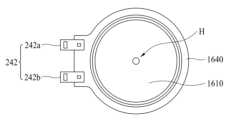
도 8a 및 도 8b는 본 명세서의 다른 실시예에 따른 음향발생장치를 포함한 표시장치를 도시한 도면이다. 도 8c는 본 명세서의 다른 실시예에 따른 음향발생장치의 저면도(bottom view)이며, 도 8d는 본 명세서의 다른 실시예에 따른 음향발생장치의 정면도(front view)이다.8A and 8B are diagrams illustrating a display device including a sound generating device according to another embodiment of the present specification. FIG. 8C is a bottom view of a sound generating device according to another embodiment of the present specification, and FIG. 8D is a front view of a sound generating device according to another embodiment of the present specification.
본 명세서의 실시예에서는 제1 구조 또는 제2 구조에 의한 음향발생장치 모두가 적용될 수 있으며, 이하에서는 제2 구조를 예로 들어 설명한다.In the embodiments of the present specification, both the first structure and the second structure of the sound generating device can be applied, and the second structure will be described below as an example.
도 8a 및 도 8b를 참조하면, 본 명세서의 실시예에 따른 표시장치(20)는 표시패널(100)과 음향발생장치(1600)를 포함할 수 있다. 음향발생장치(1600)는 표시패널(100) 내에 배치될 수 있다. 예를 들면, 음향발생장치(1600)는 표시패널(100)과 지지부재(300) 사이에 배치될 수 있다.Referring to FIGS. 8A and 8B , the
음향발생장치(1600)는 플레이트(1610) 상에 있는 마그네트(1620), 마그네트(1620) 상에 있는 센터폴(1630), 마그네트(1620)와 센터폴(1630) 주위에 있는 보빈(1650), 및 보빈(1650) 외곽에 권취되어 있는 코일(1660) 등을 포함할 수 있다. 플레이트(1610) 외측에는 프레임(1650)이 배치될 수 있다. 그리고, 프레임(1640)과 보빈(1650) 사이에는 댐퍼(1670)가 배치될 수 있다. 음향발생장치에 대한 설명은 도 2에서 설명한 내용과 동일하므로, 여기서는 상세한 설명을 생략한다.The
플레이트(1610)의 연장부(1612)를 포함할 수 있다. 다른 예로는, 도 8b에 도시한 바와 같이, 연장부 없이 음향발생장치를 구성할 수 있다. 연장부가 없을 경우, 음향발생장치를 제조하기 위한 사출물 성형을 줄일 수 있으므로, 음향발생장치의 제조단가를 줄일 수 있는 장점이 있다.It may include an
도 7에서 설명한 바와 같이, 너트의 제작 시에 발생하는 지지부재(300)의 휨을 방지하기 위해서 음향발생장치(1600)의 고정을 너트 없이 구성할 수 있고, 지지부재(300)의 휨에 의해 표시패널(100)의 진동축이 이동되지 않도록 하기 위해서 표시패널의 진동축과 음향발생장치의 중앙과 일치할 수 있도록 구성하여야 함을 인식하였다. 여러 실험을 통하여, 플레이트(1610)에 나사탭을 넣어 너트 없이 지지부재(300)에 장착될 수 있으며, 표시패널의 진동축이 이동하지 않는 새로운 구조의 표시장치를 발명하였다. 도 8a 및 도 8b를 참조하면, 지지부재(300)의 하측에는 연결부재(1820)가 배치될 수 있다. 예를 들면, 연결부재(1820)는 지지부재(300)와 음향발생장치(1600)의 사이에 배치될 수 있다. 예를 들면, 연결부재(1820)는 지지부재(300)와 음향발생장치(1600)의 플레이트(1610) 사이에 배치될 수 있다. 예를 들면, 연결부재(1820)는 지지부재(300)를 관통하여 배치될 수 있다. 예를 들면, 연결부재(1820)는 지지부재(300)의 하측을 관통하여 플레이트(1610)의 내부까지 연장될 수 있다. 연결부재(1820)는 적어도 하나의 음향발생장치(1600)의 중앙 또는 중심에 대응되도록 배치될 수 있다. 연결부재(1820)는 적어도 하나의 음향발생장치(1600)의 중앙축 또는 중심축에 대응되도록 배치될 수 있다. 예를 들면, 연결부재(1820)는 마그네트(1620) 및 센터폴(1630)의 중앙에 대응되도록 배치될 수 있다. 연결부재(1820)는 마그네트(1620) 및 센터폴(1630)의 중앙축 또는 중심축에 대응되도록 배치될 수 있다. 연결부재(1820)에는 나사가 포함될 수 있다. 따라서, 연결부재(1820)에 의해 음향발생장치(1600)가 지지부재(300) 내에 고정될 수 있다. 연결부재(1820)가 배치되는 위치는 음향발생장치(1600)의 중앙, 예를 들면, 마그네트(1620)의 크기와 대응되는 범위일 수 있으며, 마그네트(1620)의 크기보다 작거나 같은 범위에 배치될 수 있다. 따라서, 연결부재(1820)는 음향발생장치(1600)의 중앙에 대응되도록 배치될 수 있으므로, 너트에 의한 지지부재(300)의 휨으로 발생하는 표시패널(100)의 진동축의 이동을 방지할 수 있다. 예를 들면, 연결부재(1820)는 표시패널(100)의 진동축과 음향발생장치(1600)의 중앙을 일치("A"로 표시)시킬 수 있다. 따라서, 표시패널(100)의 진동축과 음향발생장치(1600)의 중앙이 일치하지 않는 롤링현상을 방지할 수 있다. 롤링현상에 의해서 발생하는 음질, 예를 들면, 고음에서의 음질이 열화되는 문제점을 방지할 수 있으며, 신뢰성이 향상될 수 있는 표시장치를 제공할 수 있다.As explained in FIG. 7, in order to prevent bending of the
도 8c를 참조하면, 플레이트(1610)에는 연결부재(1820)를 고정하기 위한 홀(H)이 배치되며, 홀(H)에는 나사산이 배치될 수 있다. 홀(H)을 통하여 연결부재(1820)에 의해 플레이트(1610)와 지지부재(300)가 고정될 수 있다. 프레임(1640)의 일측에는 외부로부터 음향 신호, 예를 들면, 보이스 신호를 인가받기 위한 배선(242)이 배치될 수 있다. 음향 신호는 음향발생장치(1600)에 공급될 수 있다. 배선(242)은 제1 배선(242a) 및 제2 배선(242b)을 포함할 수 있다. 제1 배선(242a)에는 +전원이 인가될 수 있고, 제2 배선(242b)에는 -전원이 인가될 수 있으며, 이에 한정되는 것은 아니다.Referring to FIG. 8C, a hole H for fixing the connecting
음향발생장치(1600)는 지지부재(300)의 지지홀 없이 지지부재(300)와 결합될 수 있다. 이에 의해 음향발생장치(1600)가 표시패널(100) 내에 배치될 수 있다. 예를 들면, 음향발생장치(1600)는 연결부재(1820)에 의하여 표시패널(100)과 지지부재(300) 사이에 배치될 수 있다. 따라서, 음향발생장치가 표시패널 내에 배치될 수 있으므로, 지지부재에 지지홀을 구성하지 않아도 되며, 지지부재의 지지홀로 인한 외부로부터의 이물질의 유입을 방지할 수 있다. 그리고, 음향발생장치가 지지부재의 후면으로 노출되지 않으므로, 음향발생장치의 손상을 방지할 수 있으며, 외관상 심미감을 갖는 표시장치를 제공할 수 있다.The
표시패널(100)은 접착부재(402)를 매개로 음향발생장치(1600)의 보빈(1650)에 부착될 수 있다. 접착부재(402)는 양면 테이프(double-sided tape), 단면 테이프(single-sided tape), 접착제, 및 본드(bond)일 수 있으며, 이에 한정되는 것은 아니다. 도 8a 및 도 8b에서와 같이, 접착부재(402)는 음향발생장치(1600)가 표시패널(100)에 부착되는 부분에 형성될 수 있다. 이에 한정하지 않고, 접착부재(402)는 표시패널(100)의 배면 전체에 형성될 수도 있다. 예를 들면, 접착부재(402)는 표시패널(100)의 배면과 음향발생장치(1600) 사이의 전체면에 형성될 수 있다.The
표시패널(100)의 배면에는 봉지 기판(102)이 배치될 수 있다. 예를 들면, 봉지 기판(102)은 외부의 충격으로부터 표시패널에 배치되어 있는 박막 트랜지스터 및 발광 소자층 등을 보호하고, 발광 소자층으로 수분이나 산소가 침투하는 것을 방지할 수 있다. 봉지 기판(102)은 인캡슐레이션(Encapsulation) 기판이라고 할 수 있다. 봉지기판(102)은 강자성체, 예를 들면, 철(Fe)과 니켈(Ni)의 합금인 인바(invar) 등의 재질로 구성될 수 있으며, 이에 한정되는 것은 아니다.An
음향발생장치(1600)가 진동할 시 발생하는 열을 줄이거나 감소시키기 위해서 표시패널(100)의 배면에는 방열부재(600)가 더 배치될 수 있다. 예를 들면, 방열부재(600)는 접착부재를 매개로 표시패널(100)의 배면에 배치될 수 있다. 방열부재(600)는 음향발생장치(1600)의 크기보다 큰 크기를 가지거나 음향발생장치(1600)를 덮도록 구성할 수 있으며, 일정한 두께를 갖는 다각판 형태 또는 원판 형태를 가질 수 있으며, 이에 한정되는 것은 아니다. 예를 들면, 방열부재(600)는 알루미늄(Al), 구리(Cu) 또는 은(Ag) 및 이들의 합금 등과 같이 열전도율이 높은 금속 재료로 구성되는 방열 시트 또는 방열 테이프일 수 있으며, 이에 한정되는 것은 아니다. 따라서, 방열부재(600)를 구성하므로, 음향발생장치(1600)의 진동 시 발생하는 열로 인한 표시패널(100)의 화질에 미치는 영향을 감소시킬 수 있다.In order to reduce or reduce heat generated when the
지지부재(300)와 표시패널(100) 사이에 파티션(700)이 배치될 수 있다. 파티션(700)은 표시패널(100)이 진동할 때 음향이 발생되는 에어갭(air gap) 또는 공간(space)일 수 있다. 음향을 발생시키거나 음향을 전달하는 에어갭 또는 공간을 파티션이라고 할 수 있다. 파티션은 인클로저(enclosure) 또는 배플(baffle)이라고 할 수 있으며, 용어에 한정되지 않는다.A
음향발생장치(1600)가 표시패널(100) 내에 배치되기 위해서는 음향발생장치(1600)의 두께가 얇도록 구성하여야 한다. 이에 본 명세서의 발명자들은 보빈의 높이(또는 두께)가 낮아짐으로 인한 음압이 낮아지는 문제점을 해결하기 위해서 보빈의 주변에 배치된 댐퍼의 면적을 넓게 하는 구조를 구현하였다. 댐퍼의 면적을 크게 할 경우, 코일로 전류를 인가하는 배선의 공간이 좁아지므로 배선과 댐퍼와의 간섭이 발생함을 인식하였다. 이에 여러 실험을 통하여, 댐퍼를 도전체로 구성하여 배선과 댐퍼의 역할을 함께 할 수 있도록 구성하였다. 예를 들면, 댐퍼는 금속 등으로 구성할 수 있으며, 실시예가 이에 한정되는 것은 아니다. 예를 들면, 댐퍼는 스테인레스스틸(staineless steel), 구리(Cu) 등으로 구성할 수 있으며, 실시예가 이에 한정되는 것은 아니다.In order for the
도 8d를 참조하면, 댐퍼(1670)의 면적이 프레임(1640)의 면적과 거의 유사함을 알 수 있다. 이에 의해 보빈의 높이 또는 두께를 낮추거나 줄일 수 있다. 그리고, 배선과 댐퍼와의 간섭을 방지하기 위해서 댐퍼가 배선의 역할을 하도록 하였으며, 이에 대해서 도 9를 참조하여 후술한다.Referring to FIG. 8D, it can be seen that the area of the
보빈(1650)의 상면에는 보빈링(1680)이 더 구성될 수 있다. 보빈링(1680)은 보빈(1650)의 상면을 덮음으로써 보빈(1650)을 보호할 수 있으므로, 외부 충격에 의한 보빈(1650)의 변형을 방지할 수 있다. 보빈(1650)과 보빈링(1680) 사이에는 접착부재가 더 배치될 수 있으며, 접착부재에 의하여 보빈(1650)과 보빈링(1680)이 부착될 수 있다. 접착부재는 양면테이프, 양면 폼패드, 단면테이프, 단면 폼패드, 접착제, 및 본드 중 하나로 구성할 수 있으며, 이에 한정되는 것은 아니다. 보빈(1650) 또는 보빈링(1680)과 표시패널(100) 사이에 접착부재(402)가 배치되며, 접착부재(402)에 의하여 표시패널(100)과 음향발생장치(1600)가 부착될 수 있다.A bobbin ring 1680 may be further formed on the upper surface of the
도 9a 내지 도 9d는 본 명세서의 다른 실시예에 따른 음향발생장치를 도시한 도면이다.9A to 9D are diagrams showing a sound generating device according to another embodiment of the present specification.
도 9a는 본 명세서의 실시예에 따른 음향발생장치의 배면도이며, 도 9b는 본 명세서의 실시예에 따른 음향발생장치의 정면도이다.Figure 9a is a rear view of a sound generating device according to an embodiment of the present specification, and Figure 9b is a front view of the sound generating device according to an embodiment of the present specification.
도 9a는 하나의 음향발생장치를 도시한 것이다. 도 9b는 두 개의 음향발생장치가 구성된 2 어레이(two array)를 도시한 것이며, 도 9c는 4개의 음향발생장치가 구성된 4 어레이(4 array)를 도시한 것이다. 도 9d는 6개의 음향발생장치가 구성된 6 어레이(6 array)를 도시한 것이다. 본 실시예에 따른 음향발생장치는 하나의 음향발생장치, 또는 2 어레이 구조 이상의 음향발생장치로 구성될 수 있으며, 이에 한정되는 것은 아니다. 음향발생장치는 도 2에서 설명한 제1 구조 또는 제2 구조에 의한 음향발생장치 모두가 적용될 수 있다.Figure 9a shows one sound generating device. Figure 9b shows a two array consisting of two sound generating devices, and Figure 9c shows a four array consisting of four sound generating devices. Figure 9d shows a 6 array consisting of 6 sound generating devices. The sound generating device according to this embodiment may be comprised of a single sound generating device or a sound generating device having a two-array structure or more, but is not limited thereto. The sound generating device may be either the first structure or the second structure described in FIG. 2.
도 9a 내지 도 9d를 참조하면, 음향발생장치의 두께를 감소시키고 마그네트의 성능을 향상시키기 위해서 댐퍼의 면적을 넓게 구성할 수 있다. 그리고, 댐퍼는 스테인레스스틸(staineless steel), 구리(Cu) 등으로 구성하여 음향발생장치로의 음향신호를 인가할 수 있는 배선이 될 수 있다.Referring to FIGS. 9A to 9D, the area of the damper can be configured to be large in order to reduce the thickness of the sound generating device and improve the performance of the magnet. In addition, the damper may be made of stainless steel, copper (Cu), etc. and can serve as a wire that can apply a sound signal to the sound generating device.
도 9a를 참조하면, 하나의 음향발생장치(1600)는 프레임(1640) 상에 댐퍼(1670)가 배치될 수 있다. 하나의 음향발생장치(1600)는 싱글타입(single type)이라고 할 수 있다.Referring to FIG. 9A, one
댐퍼(1670)는 배선의 역할을 하도록 구성하므로, +전원(또는 음향신호)이 인가되는 제1 댐퍼(1670a)와 -전원(또는 음향신호)이 인가되는 제2 댐퍼(1670b)로 구성될 수 있다. 댐퍼(1670)는 가로방향을 기준으로 나누어지며, +전원이 인가되는 제1 댐퍼(1670a)는 도면의 정면을 기준으로 위 부분일 수 있고, -전원이 인가되는 제2 댐퍼(1670b)는 도면의 정면을 기준으로 아래 부분일 수 있다. 예를 들면, 제1 댐퍼(1670a)는 제1 배선(242a)에 연결되고, 제2 댐퍼(1670b)는 제2 배선(242b)에 연결될 수 있다. 댐퍼의 형상(S)은 지그재그 형상으로 구성할 수 있다. 사선으로 구성할 경우, 댐퍼의 상하운동에 의하여 끊어짐이 발생할 수 있으며, 댐퍼의 길이를 길게 할 경우 공진주파수에 영향을 줄 수 있다. 예를 들면, C와 D로 표시된 부분의 두께는 일정하게 구성하고 폭을 다르게 구성하므로, 겹치는 부분에서의 끊어짐을 방지할 수 있다.Since the
도 9b를 참조하면, 두 개의 음향발생장치(1900)는 프레임(1640) 상에 댐퍼(1670)가 배치될 수 있다. 두 개의 음향발생장치(1900)는 트윈타입(twin type)이라고 할 수 있다.Referring to FIG. 9B, the two
댐퍼는 병렬로 연결될 수 있다. 댐퍼(1670)는 배선을 역할을 하도록 구성하므로, +전원이 인가되는 제1 댐퍼(1670a)와 -전원이 인가되는 제2 댐퍼(1670b)로 구성될 수 있다. 댐퍼(1670)는 가로방향을 기준으로 나누어지며, +전원이 인가되는 제1 댐퍼(1670a)는 도면의 정면을 기준으로 위 부분일 수 있고, -전원이 인가되는 제2 댐퍼(1670b)는 도면의 정면을 기준으로 아래 부분일 수 있다. 예를 들면, 제1 댐퍼(1670a)는 제1 배선(242a)에 연결되고, 제2 댐퍼(1670b)는 제2 배선(242b)에 연결될 수 있다. 예를 들면, 두 개의 제1 댐퍼(1670a) 각각은 일체로 연결되어 제1 배선(242a)에 연결될 수 있으며, 두 개의 제2 댐퍼(1670b) 각각은 일체로 연결되어 제2 배선(242b)에 연결될 수 있다. 그리고, 댐퍼의 형상에 대한 설명은 도 9a에서 설명한 내용과 동일 또는 유사하게 적용될 수 있다.Dampers can be connected in parallel. Since the
도 9c를 참조하면, 4 개의 음향발생장치(2020)는 프레임(1640) 상에 댐퍼(1670)가 배치될 수 있다. 4 개의 음향발생장치(2020)는 쿼드타입(quad type)이라고 할 수 있다.Referring to FIG. 9C, the four
댐퍼는 병렬 및 직렬로 연결될 수 있다. 댐퍼(1670)는 배선을 역할을 하도록 구성하므로, +전원이 인가되는 제1 댐퍼(1670a)와 -전원이 인가되는 제2 댐퍼(1670b)로 구성될 수 있다. 댐퍼(1670)는 가로방향을 기준으로 나누어지며, +전원이 인가되는 제1 댐퍼(1670a)는 도면의 정면을 기준으로 위 부분일 수 있고, -전원이 인가되는 제2 댐퍼(1670b)는 도면의 정면을 기준으로 아래 부분일 수 있다. 제1 댐퍼(1670a)의 각각은 제1 배선(242a)에 연결되고, 제2 댐퍼(1670b)의 각각은 제2 배선(242b)에 연결될 수 있다. 예를 들면, 두 개의 제1 댐퍼(1670a) 각각은 일체로 연결되어 제1 배선(242a)에 연결될 수 있으며, 두 개의 제2 댐퍼(1670b) 각각은 일체로 연결되어 제2 배선(242b)에 연결될 수 있다. 그리고, 댐퍼의 형상에 대한 설명은 도 9a에서 설명한 내용과 동일하게 적용될 수 있다.Dampers can be connected in parallel and series. Since the
도 9d를 참조하면, 6 개의 음향발생장치(2000)는 프레임(1640) 상에 댐퍼(1670)가 배치될 수 있다. 6 개의 음향발생장치(2000)는 헥사타입(Hexa type)이라고 할 수 있다.Referring to FIG. 9D, six
댐퍼는 병렬 및 직렬로 연결될 수 있다. 댐퍼(1670)는 배선을 역할을 하도록 구성하므로, +전원이 인가되는 제1 댐퍼(1670a)와 -전원이 인가되는 제2 댐퍼(1670b)로 구성될 수 있다. 댐퍼(1670)는 가로방향을 기준으로 나누어지며, 도면의 좌측 및 우측에 위치한 댐퍼에서, +전원이 인가되는 제1 댐퍼(1670a)는 도면의 정면을 기준으로 좌측 부분일 수 있고, -전원이 인가되는 제2 댐퍼(1670b)는 도면의 정면을 기준으로 우측 부분일 수 있다. 그리고, 도면의 중앙에 위치한 제1 댐퍼(1670a)는 우측 부분일 수 있고, 제2 댐퍼(1670b)는 좌측 부분일 수 있다. 예를 들면, 제1 댐퍼(1670a)의 각각은 제1 배선(242a)에 연결되고, 제2 댐퍼(1670b)의 각각은 제2 배선(242b)에 연결될 수 있다. 예를 들면, 두 개의 제1 댐퍼(1670a) 각각은 일체로 연결되어 제1 배선(242a)에 연결될 수 있으며, 두 개의 제2 댐퍼(1670b) 각각은 일체로 연결되어 제2 배선(242b)에 연결될 수 있다. 그리고, 댐퍼의 형상에 대한 설명은 도 9a에서 설명한 내용과 동일하게 적용될 수 있다.Dampers can be connected in parallel and series. Since the
따라서, 본 명세서의 실시예에 따른 음향발생장치는 지지부재의 지지홀 없이 음향발생장치를 배치할 수 있으므로, 음향발생장치의 배치 자유도가 향상될 수 있다.Therefore, in the sound generating device according to an embodiment of the present specification, the sound generating device can be arranged without a support hole in the support member, and thus the degree of freedom in arranging the sound generating device can be improved.
도 8에서 설명한 바와 같이, 너트의 제작 시에 발생하는 지지부재(300)의 휨을 방지하기 위해서 음향발생장치(1600)의 고정을 너트 없이 구성할 수 있고, 지지부재(300)의 휨에 의해 표시패널(100)의 진동축이 이동되지 않도록 하기 위해서 표시패널의 진동축과 음향발생장치의 중앙이 일치할 수 있도록 구성하였다. 그리고, 도 9a 내지 도 9d에서 설명한 바와 같이, 작은 면적을 갖는 음향발생장치로 구현할 경우 표시패널이 이동하게 되므로, 표시패널의 이동을 방지하기 위해서 표시패널의 가장자리를 강하게 고정하여야 한다. 표시패널의 가장자리를 너무 강하게 고정하게 될 경우, 표시패널의 진동이 약해지고, 표시패널의 진동이 약해지면 음압이 낮아지게 되고, 저음에서의 음향이 저하되는 문제점이 생김을 인식하였다. 이에 본 명세서의 발명자들은 여러 실험을 통하여, 저음에서의 음향을 개선할 수 있는 새로운 구조의 표시장치를 발명하였다. 이에 대해서 도 10을 참조하여 설명한다.As explained in FIG. 8, in order to prevent bending of the
도 10a 및 도 10b는 본 명세서의 다른 실시예에 따른 음향발생장치를 포함한 표시장치를 도시한 도면이다.10A and 10B are diagrams illustrating a display device including a sound generating device according to another embodiment of the present specification.
본 명세서의 실시예에서는 제1 구조 또는 제2 구조에 의한 음향발생장치 모두가 적용될 수 있으며, 이하에서는 제2 구조를 예로 들어 설명한다.In the embodiments of the present specification, both the first structure and the second structure of the sound generating device can be applied, and the second structure will be described below as an example.
도 10a 및 도 10b을 참조하면, 본 명세서의 실시예에 따른 표시장치(30)는 표시패널(100)과 음향발생장치(1600)를 포함할 수 있다. 음향발생장치(1600)는 표시패널(100) 내에 배치될 수 있다. 예를 들면, 음향발생장치(1600)는 표시패널(100)과 지지부재(300) 사이에 배치될 수 있다. 음향발생장치(1600) 및 방열부재(600)에 대한 설명은 도 8a 내지 도 8d에서 설명한 내용과 동일하므로, 여기서는 설명을 생략한다. 도 10b는 도 8b에서 설명한 바와 같이, 연장부 없이 구성한 것이며, 연장부가 없을 경우, 음향발생장치를 제조하기 위한 사출물 성형을 줄일 수 있으므로, 음향발생장치의 제조단가를 줄일 수 있는 장점이 있다.Referring to FIGS. 10A and 10B , the
본 명세서의 실시예에 따른 표시장치(30)는 표시패널(100)의 상면 및 측면에 배치되는 커버(303)를 포함할 수 있다. 커버(303)는 표시패널(100)을 보호하고 지지할 수 있다. 커버(303)는 케이스 탑(case top)일 수 있으며, 용어에 한정되는 것은 아니다. 일 예에 따른 커버(303)는 플라스틱 재질, 금속 재질, 또는 플라스틱 재질과 금속 재질의 혼합 재질로 이루어질 수 있으며, 이에 한정되는 것은 아니다. 커버(303)와 표시패널(100) 사이에는 패드부(702)가 더 구성될 수 있다. 예를 들면, 패드부(702)는 커버(303)의 하면과 표시패널(100)의 상면 사이에 배치될 수 있다. 커버(303)가 있는 경우에 표시패널(100)의 면적이 작아지므로, 패드부(702)를 구성하여, 면적이 작은 표시패널(100)에서 표시패널(100)이 이동하면서 발생하는 롤링현상을 방지할 수 있다. 따라서, 패드부(702)는 표시패널(100)을 고정할 수 있으므로, 표시패널(100)의 이동을 방지할 수 있다. 패드부(702)는 표시패널(100)의 이동에 따른 표시패널(100)의 진동이 약해지는 것을 방지할 수 있으므로, 음향발생장치(1600)의 저음을 개선할 수 있다. 패드부(702)는 폼패드 또는 폼테입으로 구성할 수 있으며, 이에 한정되는 것은 아니다. 패드부(702)는 파티션일 수 있으며, 용어에 한정되는 것은 아니다. 패드부(702)는 파티션(700)과 동일한 재질로 구성할 수 있으며, 이에 한정되는 것은 아니다. 다른 예로는, 패드부(702)는 파티션(700)과 다른 재질로 구성할 수 있다. 예를 들면, 패드부(702)와 파티션(700)은 강성(stiffness)이 서로 다른 재질로 구성할 수 있다. 패드부(702)는 단면테이프로 구성하고, 파티션(700)은 양면테이프로 구성할 수 있다. 다른 예로는, 패드부(702)는 양면테이프로 구성하고, 파티션(700)은 단면테이프로 구성할 수 있다.The
도 11a 내지 도 11d는 본 명세서의 실시예에 따른 음향발생장치와 파티션의 실시예를 도시한 도면이다.11A to 11D are diagrams showing examples of a sound generating device and a partition according to an embodiment of the present specification.
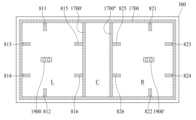
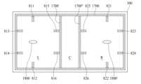
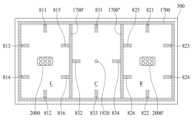
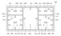
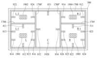
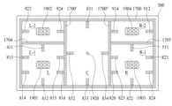
도 11a 내지 도 11d를 참조하면, 표시패널(100)은 제1 영역(L), 제2 영역(R), 및 제3 영역(C)을 포함할 수 있다. 제1 영역(L)은 표시패널(100)의 배면의 좌측영역, 제2 영역(R)은 표시패널(100)의 배면의 우측영역, 및 제3 영역(C)은 표시패널(100)의 배면의 중앙영역일 수 있다. 제1 영역(L), 제2 영역(R), 및 제3 영역(C) 중 적어도 하나의 영역에는 적어도 하나의 음향발생장치가 배치될 수 있다. 적어도 하나의 음향발생장치는 타원형의 음향발생장치, 한쌍의 음향발생장치, 원형의 음향발생장치, 싱글타입 음향발생장치, 및 2 어레이 이상의 음향발생장치 중 적어도 하나 이상을 포함할 수 있다. 타원형(oval shape)은 타원형(elliptical shape), 끝이 둥근 사각형(a rectangular shape with rounded corners), 또는 폭이 높이와 다른 비원형 곡선형(non-circular curved shape having a width different from its height)을 포함할 수 있으며, 실시예는 이에 한정되지 않는다. 적어도 하나의 음향발생장치는 표시패널을 진동시켜 음향을 발생시킬 수 있다. 예를 들면, 적어도 하나의 음향발생장치는 표시패널을 직접 진동시켜 음향을 발생시킬 수 있다.Referring to FIGS. 11A to 11D , the
도 11a에서 제1 음향발생장치(1600) 및 제2 음향발생장치(1600')는 도 9a에서 원형의 음향발생장치로 구성할 수 있다. 도 11b에서 제1 음향발생장치(1900) 및 제2 음향발생장치(1900')는 도 9b에서 설명한 음향발생장치로 구성할 수 있다. 예를 들면, 두 개의 음향발생장치로 구성할 수 있다. 제1 음향발생장치(1900) 및 제2 음향발생장치(1900')는 제1 영역(L) 및 제2 영역(R)에서 서로 다른 중고음역대의 음향을 출력할 수 있다. 예를 들면, 300Hz 내지 20kHZ의 범위의 음향을 출력할 수 있으며, 이 범위에 한정되는 것은 아니다. 도 11c에서 제1 음향발생장치(2000) 및 제2 음향발생장치(2000')는 도 9d에서 설명한 음향발생장치로 구성할 수 있다. 예를 들면, 6 개의 음향발생장치로 구성할 수 있다. 제1 음향발생장치(2000) 및 제2 음향발생장치(2000')는 제1 영역(L) 및 제2 영역(R)에서 서로 다른 중고음역대의 음향을 출력할 수 있다. 예를 들면, 200Hz 내지 20kHZ의 범위의 음향을 출력할 수 있으며, 이 범위에 한정되는 것은 아니다. 도 11d에서 제1 음향발생장치(1800) 및 제2 음향발생장치(1800')는 도 9a에서 설명한 원형을 타원형으로 적용한 것이다.The first
도 11a를 참조하면, 제1 음향발생장치(1600) 및 제2 음향발생장치(1600')는 표시패널의 제1 영역(L) 및 제2 영역(R)에 각각 배치될 수 있다. 예를 들면, 제1 음향발생장치(1600)는 표시패널(100)의 배면의 제1 영역(L)에 배치될 수 있고, 제2 음향발생장치(1600')는 표시패널(100)의 배면의 제2 영역(R)에 배치될 수 있다. 도 8 및 도 10에서 설명한 바와 같이, 제1 음향발생장치(1600) 및 제2 음향발생장치(1600')는 표시패널(100) 내에 배치될 수 있다.Referring to FIG. 11A , the first
따라서, 제1 음향발생장치(1600)는 표시패널(100)의 배면의 좌측영역인 제1 영역(L)에 배치되어 표시패널(100)의 좌측영역을 진동시킬 수 있으며, 제2 음향발생장치(1600')는 표시패널(100) 배면의 우측영역인 제2 영역(R)에 배치되어 표시패널(100)의 우측영역을 진동시킬 수 있다. 제1 및 제2 음향발생장치(1600, 1600') 각각은 서로 다른 진동 신호를 수신하여 독립적으로 구동될 수 있다. 예를 들면, 제1 음향발생장치(1600)는 표시패널(100)의 배면의 좌측영역을 진동판으로 사용함으로써 음향을 발생시킬 수 있으며, 제2 음향발생장치(1600')는 표시패널(100)의 배면의 우측영역을 진동판으로 사용함으로써 음향을 발생시킬 수 있다. 이에 대한 설명은 도 11b 내지 도 18d에도 동일하거나 유사하게 적용될 수 있다. 그리고, 도 8 및 도 10에서 설명한 내용이 동일하거나 유사하게 적용될 수 있다.Accordingly, the first
파티션 및 패드에 대한 설명은 도 11a를 예로 들어 설명하며, 이에 대한 설명은 도 11b 내지 도 11d에서도 동일하거나 유사하게 적용될 수 있다.The description of the partition and pad is explained using FIG. 11A as an example, and the description may be applied in the same or similar manner to FIGS. 11B to 11D.
도 11a 내지 도 11d를 참조하면, 제1 파티션(1700)은 표시패널과 지지부재(300) 사이에 배치될 수 있다. 예를 들면, 제1 파티션(1700)은 표시패널의 배면과 지지부재의 상면 사이에 배치될 수 있다. 제1 파티션(1700)은 지지부재(300)에 배치될 수 있다. 예를 들면, 제1 파티션(1700)은 지지부재의 가장자리 또는 지지부재의 상면의 가장자리에 배치될 수 있다. 제1 파티션(1700)은 표시패널의 가장자리에 배치될 수 있다. 예를 들면, 제1 파티션(1700)은 표시패널의 배면의 가장자리에 배치될 수 있다. 제1 파티션(1700)은 표시패널의 배면 또는 지지부재의 전체 영역일 수도 있다. 제1 파티션(1700)은 표시패널(100)의 배면의 외곽의 네 변의 전체 영역일 수도 있다. 또는, 제1 파티션(1700)은 지지부재(300)의 상면의 외곽의 네 변의 전체 영역일 수도 있다. 제1 파티션(1700)은 밀봉된 구조로 형성될 수도 있고, 밀봉되지 않은 구조로 형성될 수도 있다.Referring to FIGS. 11A to 11D , the
제1 파티션(1700)은 음향발생장치에 의하여 표시패널(100)이 진동할 때 음향이 발생되는 에어갭(air gap) 또는 공간(space)일 수 있다. 음향을 발생시키거나 음향을 전달하는 에어갭 또는 공간을 파티션이라고 할 수 있다. 제1 파티션(1700)은 인클로저(enclosure) 또는 배플(baffle)이라고 할 수 있으며, 용어에 한정되지 않는다.The
도 11a를 참조하면, 제1 음향발생장치(1600)와 제2 음향발생장치(1600')의 사이에는 적어도 두 개의 파티션인 제2 파티션(1700') 및 제3 파티션(1700")이 배치될 수 있다. 제2 파티션(1700') 및 제3 파티션(1700") 중 하나는 제1 음향발생장치(1600)와 제2 음향발생장치(1600')의 사이에 두 개 이상의 서브 파티션으로 구성되어 있다고 할 수도 있다. 예를 들면, 제1 영역(L) 및 제3 영역(C) 사이에는 제2 파티션(1700')이 배치될 수 있고, 제2 영역(R) 및 제3 영역(C) 사이에는 제3 파티션(1700")이 배치될 수 있다.Referring to FIG. 11A, at least two partitions, a second partition 1700' and a
제1 파티션(1700)은 제1 영역(L), 제2 영역(R), 및 제3 영역(C)을 둘러싸도록 배치될 수 있다. 제1 파티션(1700), 제2 파티션(1700'), 및 제3 파티션(1700")은 표시패널(100)의 배면에 배치될 수 있다. 제1 파티션(1700), 제2 파티션(1700'), 및 제3 파티션(1700")은 지지부재(300)의 배면 또는 상면에 배치될 수 있다. 그리고, 제1 파티션(1700), 제2 파티션(1700'), 및 제3 파티션(1700")은 표시패널(100)과 지지부재(300) 사이에 배치될 수 있다. 예를 들면, 제1 파티션(1700), 제2 파티션(1700'), 및 제3 파티션(1700")은 표시패널(100)의 배면과 지지부재(300)의 상면 사이에 배치될 수 있다.The
제2 파티션(1700') 및 제3 파티션(1700")은 제1 음향발생장치(1600) 및 제2 음향발생장치(1600')에 의하여 표시패널(100)이 진동할 때 음향이 발생되는 에어갭(air gap) 또는 공간(space)일 수 있다. 음향을 발생시키거나 음향을 전달하는 에어갭 또는 공간을 파티션이라고 할 수 있다. 제2 파티션(1700') 및 제3 파티션(1700")은 인클로저(enclosure) 또는 배플(baffle)이라고 할 수 있으며, 용어에 한정되지 않는다. 제2 파티션(1700') 및 제3 파티션(1700")은 제1 음향발생장치(1600) 및 제2 음향발생장치(1600')에서 발생되는 좌우 음향을 분리할 수 있다. 제2 파티션(1700') 및 제3 파티션(1700")으로 정해질 수 있는 공간(space) 또는 에어갭(air gap)에서의 표시패널(100)의 진동을 표시패널(100)의 중앙에서 감쇄 또는 흡수하므로, 좌측영역에서의 음향이 우측영역의 공간으로 전달되는 것을 차단하거나 줄일 수 있다. 따라서, 제2 파티션(1700') 및 제3 파티션(1700")을 구성하므로, 좌우 음향을 분리할 수 있으며, 음향출력특성을 향상시킬 수 있다. 제1 음향발생장치(1600) 및 제2 음향발생장치(1600')는 서로 다른 중고음역대의 음향이 출력될 수 있으며, 좌우 음향분리에 의한 스테레오 음향이 출력될 수 있으며, 2채널 형태의 음향출력특성을 갖는 표시장치를 제공할 수 있다. 따라서, 표시패널에 파티션을 구성함으로써, 표시패널의 좌우영역에서의 중고음의 공명진동수의 차이로 인한 음향특성의 영향을 줄일 수 있다. 예를 들면, 중음역대는 200Hz~3kHz, 고음역대는 3kHz 이상일 수 있으며, 저음역대는 200Hz 이하일 수 있으며, 이에 한정되는 것은 아니다.The second partition 1700' and the
좌측영역인 제1 영역(L)에 제1 음향발생장치(1600) 및 우측영역인 제2 영역(R)에 제2 음향발생장치(1600')로 구성하고, 중앙영역인 제3 영역(C)에는 음향발생장치를 구성하지 않을 수 있다. 이로 인해서, 제1 영역(L) 및 제2 영역(R)에서의 간섭으로 인한 음질 열화를 감소시킬 수 있다. 그리고, 중고음역대의 음향특성을 더 향상시킬 수 있는 효과가 있다.It is composed of a first
제1 영역(L)의 면적 및 제2 영역(R)의 면적은 제3 영역(C)의 면적보다 크게 구성될 수 있다. 제1 영역(L)의 면적 및 제2 영역(R)의 면적이 커지므로, 저음역대의 음향이 향상될 수 있으며, 제3 영역(C)은 제1 영역(L) 및 제2 영역(R)에서의 간섭으로 인한 음질의 열화를 감소시킬 수 있다. 이에 의해, 저중고음역대의 음질을 향상시킬 수 있다.The area of the first area (L) and the area of the second area (R) may be larger than the area of the third area (C). Since the area of the first area (L) and the area of the second area (R) are increased, the sound in the low range can be improved, and the third area (C) is divided into the first area (L) and the second area (R). ) can reduce the deterioration of sound quality due to interference. As a result, the sound quality in the low, middle, and high registers can be improved.
도 11a 내지 도 18d에서 제1 파티션(1700)이 도 1에서 설명한 접착부재일 수 있다. 도 1에서 설명한 표시패널과 지지부재 사이에는 표시패널과 지지부재를 접착시키는 접착부재가 더 배치될 수 있다. 예를 들면, 표시패널의 가장자리 또는 지지부재의 가장자리에 접착부재가 더 배치될 수 있다.11A to 18D, the
도 11a 내지 도 12d는 음향발생장치가 표시패널(100)의 제1 영역(L)인 좌측영역 또는 제2 영역(R)인 우측영역의 중앙에 위치하지 않고, 좌측영역 또는 우측영역으로 치우쳐 배치된 것을 도시한 것이다. 이에 한정하지 않고, 음향발생장치가 표시패널(100)의 제1 영역(L)인 좌측영역 또는 제2 영역(R)인 우측영역의 중앙에 배치될 수도 있다. 또는, 음향발생장치가 표시패널의 제1 영역(L) 및 제2 영역(R)에서 비대칭적으로 배치되어 있다고 할 수 있다. 음향발생장치가 표시패널(100)의 제1 영역(L)인 좌측영역의 중앙 또는 제2 영역(R)인 우측영역의 중앙에 위치하는 경우보다 좌측영역 또는 우측영역으로 치우쳐 위치할 경우, 스테레오 음향특성이 더 향상될 수 있다.11A to 12D, the sound generating device is not located in the center of the left area (the first area (L)) or the right area (the second area (R)) of the
얇은 두께의 표시장치를 구현하기 위해서 표시장치에 포함된 기판의 두께를 얇게 구성할 수 있다. 기판의 두께가 얇아지면서, 파티션이 표시패널의 배면 또는 지지부재의 상면에 구현될 경우에, 표시패널과 지지부재가 부착될 시에 파티션으로 인하여 표시패널 자체 또는 지지부재가 평평하지 않고 표시패널 또는 지지부재에서의 단차가 생기는 문제점이 발생하였다. 예를 들면, 패드의 형상 등으로 이하여 표시패널의 화면으로 두드러지는 형상이 발생하며, 표시패널이 평평하지 않는, 또는 지지부재가 평평하지 않는, 울퉁불퉁하게 시인되는 문제점이 발생하였다. 이러한 현상을 표시패널 또는 지지부재의 울퉁불퉁한 현상 또는 웨이브(wave) 현상(이하 "웨이브 현상"이라 함)이라 할 수 있으며, 용어에 한정되는 것은 아니다. 따라서, 패두부의 형상 및 따른 파티션의 형상에 대해서 여러 실험을 하였다. 여러 실험을 통하여 제1 파티션(1700)은 표시패널(100)의 형태를 따라 배치하여야 함을 인식하였다. 예를 들면, 제1 파티션(1700)은 사각형의 형태를 가질 수 있으며, 이에 한정하지 않고 표시패널의 형태에 따라 변경될 수 있다. 표시패널이 곡선 형태 등을 포함하는 커브드(curved) 또는 곡선형 표시패널일 경우, 제1 파티션은 커브드 형태 또는 곡선 형태를 가질 수 있다. 따라서, 제1 파티션(1700)이 표시패널의 형태를 따라 배치됨으로써, 표시패널(100)과 지지부재와의 부착 시에 표시패널(100)이 당겨짐이 줄어들 수 있으므로, 웨이브 현상이 방지될 수 있다.In order to implement a thin display device, the thickness of the substrate included in the display device can be configured to be thin. As the thickness of the substrate becomes thinner, when a partition is implemented on the back of the display panel or the upper surface of the support member, when the display panel and the support member are attached, the display panel itself or the support member is not flat due to the partition and the display panel or the support member is not flat. A problem occurred where a level difference occurred in the support member. For example, due to the shape of the pad, etc., a shape that stands out on the screen of the display panel occurs, and a problem arises in which the display panel is not flat or the support member is not flat and is viewed as uneven. This phenomenon may be referred to as an uneven phenomenon or wave phenomenon (hereinafter referred to as “wave phenomenon”) of the display panel or support member, but is not limited to these terms. Therefore, several experiments were conducted on the shape of the head of the shell and the shape of the corresponding partition. Through various experiments, it was recognized that the
음향발생장치에 의하여 표시패널이 진동하여 발생되는 음파는 음향발생장치의 중앙으로부터 방사상으로 퍼지면서 진행할 수 있다. 이 음파를 진행파(progressive wave)라고 할 수 있다. 이 진행파가 파티션의 한 변에서 만나는 경우 파티션에서 반사되어 진행파와 반대방향으로 진행하는 반사파(reflected wave)를 형성하게 된다. 이 반사파는 진행파와 중첩 및 간섭되어, 중첩된 음파가 진행하지 못하고 일정한 위치에 정체되어 있는 정재파(standing wave)를 형성하게 된다. 이 정재파에 의하여 음압이 감소되어 음향출력특성이 나빠질 수 있다.The sound wave generated by the display panel vibrating by the sound generating device may spread radially from the center of the sound generating device. This sound wave can be called a progressive wave. When this traveling wave meets one side of a partition, it is reflected from the partition and forms a reflected wave that travels in the opposite direction to the traveling wave. This reflected wave overlaps and interferes with the traveling wave, forming a standing wave in which the superimposed sound wave cannot proceed and stagnates at a certain location. This standing wave may reduce the sound pressure and worsen the sound output characteristics.
그러나, 제1 파티션(1700)으로 구성할 경우 정재파에 의한 피크나 딥 현상을 제어할 수 없으므로, 제1 파티션(1700)에 정재파에 의한 피크나 딥 현상을 제어하기 위한 구조를 구성하여야 함을 인식하였다. 피크는 특정주파수에서 음압이 튀는 현상이며, 딥은 특성 주파수의 발생이 억제되어 낮은 음압이 발생되는 현상이다. 피크 또는 딥 현상에 의해 표시장치의 음향출력특성이 저하될 수 있다. 피크나 딥 현상을 제어하기 위한 구조는 웨이브 현상을 방지하고, 정재파에 의한 피크나 딥 현상의 제어에도 용이할 수 있도록 구성하여야 한다. 이 구조를 단순히 구현하는 것이 아니라, 여러 실험을 통하여 구현하였다. 따라서, 제1 및 제2 음향발생장치(1600, 1600')의 세로방향으로 발생하는 정재파에 의한 피크(peak)와 딥(dip) 현상을 줄이기 위해서 제1 파티션(1700)에 패드를 구성할 수 있다. 이에 의해, 반사파와 진행파의 간섭에 의하여 발생되는 정재파에 의한 음압 감소 현상을 줄일 수 있다. 그리고, 음압 감소를 일으키는 정재파는 진행파와 반사파의 크기가 큰 지점에서 많이 발생할 수 있다. 따라서, 패드는 음향발생장치로부터 도달하는 음파가 가장 큰 위치에 배치될 수 있다. 예를 들면, 제1 파티션(1700)의 하나 이상의 변에는 패드가 구성될 수 있다. 패드는 제1 파티션(1700)의 네 개의 변 중에서 가장 강한 음파가 도착되는 하나 이상의 변에 형성하고, 제1 및 제2 음향발생장치(1600, 1600')를 향하도록 구성될 수 있다.However, when configured with the
패드의 형상은 지지부재에 배치된 패드가 표시패널(100)에 부착될 시에 표시패널(100)의 당김에 의한 웨이브 현상이 방지될 수 있도록 구성할 수 있다. 또는, 표시패널(100)에 배치된 패드가 지지부재에 부착될 시에 표시패널(100)의 당김에 의한 웨이브 현상이 방지될 수 있도록 구성할 수 있다. 예를 들면, 음향발생장치의 정재파에 의한 피크나 딥 현상의 제어에 용이하여야 하며, 웨이브 현상이 방지될 수 있도록 구현하여야 한다. 여러 실험을 통하여 패드는 사각형 또는 끝이 둥근 사각형의 형상으로 구현하였다.The shape of the pad may be configured to prevent a wave phenomenon caused by pulling of the
도 11a를 참조하면, 정재파에 의한 피크나 딥 현상을 줄이기 위해서 제1 파티션(1700)의 적어도 하나 이상의 변에 패드를 구성할 수 있다. 예를 들면, 제1 파티션(1700)은 제1 변, 및 제1 변과 수직인 제2 변을 포함할 수 있디. 제1 변에는 적어도 하나의 제1 패드(811) 및 적어도 하나의 제7 패드(821)가 구성될 수 있다. 적어도 하나의 제1 패드(811)는 제1 영역(C)에 배치될 수 있으며, 적어도 하나의 제7 패드(821)는 제2 영역(R)에 배치될 수 있다. 적어도 하나의 제1 패드(811) 및 적어도 하나의 제7 패드(821)는 적어도 하나 이상 구성할 수 있다. 제1 변은 표시패널(100) 또는 지지부재(300)의 가로방향일 수 있고, 제2 변은 표시패널(100) 또는 지지부재(300)의 세로방향일 수 있다. 가로방향 및 세로방향은 서로 혼용하여 사용할 수 있다.Referring to FIG. 11A, a pad may be formed on at least one side of the
적어도 하나의 제2 패드(812)는 적어도 하나의 제1 패드(811)와 마주보며 배치될 수 있다. 예를 들면, 적어도 하나의 제2 패드(812)는 적어도 하나의 제1 패드(811)와 마주보는 변에 배치될 수 있다. 적어도 하나의 제2 패드(812)는 제1 영역(L)에 배치될 수 있다. 적어도 하나의 제2 패드(812)는 적어도 하나 이상 구성할 수 있다.At least one
적어도 하나의 제8 패드(822)는 적어도 하나의 제7 패드(821)와 마주보며 배치될 수 있다. 예를 들면, 적어도 하나의 제8 패드(822)는 적어도 하나의 제7 패드(821)와 마주보는 변에 배치될 수 있다. 적어도 하나의 제8 패드(822)는 제2 영역(R)에 배치될 수 있다. 적어도 하나의 제8 패드(822)는 적어도 하나 이상 구성할 수 있다.At least one
제1 파티션(1700)의 제1 변과 마주보는 변에는 제2 패드(812) 및 제8 패드(822)가 더 구성될 수 있다. 제1 영역(L)에서 제1 파티션(1700)의 제1 변과 마주보는 변에 제2 패드(812)가 배치되고, 제2 영역(R)에서 제1 파티션(1700)의 제1 변과 마주보는 변에 제8 패드(822)가 배치될 수 있다. 제2 패드(812)는 제1 패드(811)와 마주보게 구성할 수 있으며, 제8 패드(822)는 제7 패드(821)와 마주보게 구성할 수 있다. 제2 패드(812) 및 제8 패드(822)는 적어도 하나 이상 구성할 수 있다.A
적어도 하나의 제1 패드(811) 및 적어도 하나의 제2 패드(812)는 제1 음향발생장치(1600)를 향하도록 구성할 수 있다. 적어도 하나의 제7 패드(821) 및 적어도 하나의 제8 패드(822)는 제2 음향발생장치(1600')를 향하도록 구성할 수 있다. 예를 들면, 제1 영역(L)에는 제1 음향발생장치(1600)를 향하도록 제1 패드(811) 및 제2 패드(812)가 배치되고, 제2 영역(R)에는 제2 음향발생장치(1600')를 향하도록 제7 패드(821) 및 제8 패드(822)가 배치될 수 있다. 따라서, 패드(811, 812, 821, 822)는 제1 및 제2 음향발생장치(1600, 1600')의 세로방향으로 발생하는 정재파에 의한 피크나 딥 현상을 줄일 수 있으며, 진동이 좌우로 전달될 수 있으므로, 음향출력특성이 향상될 수 있다.At least one
제1 파티션(1700)의 제2 변에는 적어도 하나의 제3 패드(813), 적어도 하나의 제4 패드(814), 적어도 하나의 제9 패드(823), 및 적어도 하나의 제10 패드(824)가 더 구성될 수 있다. 다른 예로는, 적어도 하나의 제3 패드(813) 및 적어도 하나의 제4 패드(814) 중 하나만 구성할 수도 있다. 다른 예로는, 적어도 하나의 제9 패드(823) 및 적어도 하나의 제10 패드(824) 중 하나만 구성할 수도 있다. 제3 패드(813), 제4 패드(814), 제9 패드(823), 및 제10 패드(824)는 제1 파티션(1700)의 하나 이상의 변에 하나 이상 구성할 수 있다. 제3 패드(813), 제4 패드(814), 제9 패드(823), 및 제10 패드(924)는 제1 영역(L) 및 제2 영역(R) 중 적어도 하나의 영역에 배치될 수 있다. 예를 들면, 제3 패드(813) 또는 제4 패드(814)는 제1 영역(L)에 배치될 수 있으며, 제9 패드(823) 또는 제10 패드(824)는 제2 영역(R)에 배치될 수 있다. 예를 들면, 제3 패드(813) 및 제4 패드(814)는 제1 음향발생장치(1600)를 기준으로 대칭적으로 배치될 수 있으며, 제9 패드(823) 및 제10 패드(824)는 제2 음향발생장치(1600')를 기준으로 대칭적으로 배치될 수 있다.On the second side of the
제1 패드 내지 제4 패드(811, 812, 813, 814) 및 제7 패드 내지 제10 패드(821, 822, 823, 824)의 형상은 사각형 또는 끝이 둥근 사각형일 수 있으며, 이에 한정하지 않고 원형 등의 다양한 형상으로 구성할 수 있다.The shape of the first to
제1 파티션(1700)은 양면테이프, 양면 폼패드, 단면테이프, 단면 폼패드, 접착제, 및 본드 중 하나로 구성할 수 있으며, 이에 한정되는 것은 아니다. 양면테이프 또는 양면 폼패드로 구성할 경우 표시패널(100)의 배면과 지지부재의 상면을 부착할 시 접착력을 향상시킬 수 있다. 예를 들면, 제1 파티션(1700)은 일정 정도 압축될 수 있는 탄성을 가지는 재질로 구현될 수 있으며, 폴리우레탄(polyurethane), 폴리올레핀(polyolefin), 및 폴리에틸렌(polyethylene) 재질로 구성할 수 있으며, 이에 한정되는 것은 아니다.The
제2 파티션(1700') 및 제3 파티션(1700") 중 하나는 제1 파티션(1700)과 동일한 재질로 구성할 수 있다. 예를 들면, 양면테이프, 양면 폼패드, 단면테이프, 단면 폼패드, 접착제, 및 본드 중 하나로 구성할 수 있으며, 이에 한정되는 것은 아니다.One of the second partition 1700' and the
적어도 하나의 제1 패드(811) 또는 적어도 하나의 제2 패드(812)는 제1 파티션(1700)과 동일한 재질로 구성할 수 있다. 적어도 하나의 제3 패드(813) 또는 적어도 하나의 제4 패드(814)는 제1 파티션(1700)과 동일한 재질로 구성할 수 있다. 적어도 하나의 제7 패드(821) 또는 적어도 하나의 제8 패드(822)는 제1 파티션(1700)과 동일한 재질로 구성할 수 있다. 적어도 하나의 제9 패드(823) 또는 적어도 하나의 제10 패드(824)는 제1 파티션(1700)과 동일한 재질로 구성할 수 있다. 예를 들면, 양면테이프, 양면 폼패드, 단면테이프, 단면 폼패드, 접착제, 및 본드 중 하나로 구성할 수 있으며, 이에 한정되는 것은 아니다.At least one
제1 패드 내지 제4 패드(811, 812, 813, 814) 및 제7 패드 내지 제10 패드(821, 822, 823, 824)는 제1 파티션(1700)과 동일한 재질로 구성할 수 있다. 제1 패드 내지 제4 패드(811, 812, 813, 814) 및 제7 패드 내지 제10 패드(821, 822, 823, 824)는 제2 파티션(1700') 또는 제3 파티션(1700")과 동일한 재질로 구성할 수 있다. 예를 들면, 제1 패드 내지 제4 패드(811, 812, 813, 814) 및 제7 패드 내지 제10 패드(821, 822, 823, 824)는 양면테이프, 양면 폼패드, 단면테이프, 단면 폼패드, 접착제, 본드 중 하나로 구성할 수 있으며, 이에 한정되는 것은 아니다.The first to
다른 예로는, 적어도 하나의 제1 패드(811)는 제1 파티션(1700)과 다른 재질로 구성할 수 있다. 제1 파티션(1700)은 양면테이프로 구성할 수 있다. 양면테이프로 구성할 경우, 단면테이프와 비교하여 웨이브 현상에는 불리하나, 표시패널과 지지부재와의 접착력이 향상될 수 있으며, 음질이 향상될 수 있다. 적어도 하나의 제1 패드(811)는 제1 파티션(1700), 제2 파티션(1700'), 및 제3 파티션(1700") 중 적어도 하나와 다른 재질로 구성할 수 있다. 적어도 하나의 제1 패드(811) 또는 적어도 하나의 제2 패드(812)는 제1 파티션(1700)과 다른 재질로 구성할 수 있다. 적어도 하나의 제1 패드(811) 또는 적어도 하나의 제2 패드(812)는 제1 파티션(1700), 제2 파티션(1700'), 및 제3 파티션(1700") 중 적어도 하나와 다른 재질로 구성할 수 있다. 적어도 하나의 제2 패드(812)는 적어도 하나의 제1 패드(811)와 동일한 재질로 구성할 수 있다. 적어도 하나의 제3 패드(813) 또는 적어도 하나의 제4 패드(814)는 제1 파티션(1700)과 다른 재질로 구성할 수 있다. 적어도 하나의 제3 패드(813) 또는 적어도 하나의 제4 패드(814)는 제1 파티션(1700), 제2 파티션(1700'), 및 제3 파티션(1700") 중 적어도 하나와 다른 재질로 구성할 수 있다. 적어도 하나의 제3 패드(813) 또는 적어도 하나의 제4 패드(814)는 적어도 하나의 제1 패드(811)와 동일한 재질로 구성할 수 있다.As another example, at least one
적어도 하나의 제7 패드(821) 또는 적어도 하나의 제8 패드(822)는 제1 파티션(1700)과 다른 재질로 구성할 수 있다. 적어도 하나의 제7 패드(821) 또는 적어도 하나의 제8 패드(822)는 제1 파티션(1700), 제2 파티션(1700'), 및 제3 파티션(1700") 중 적어도 하나와 다른 재질로 구성할 수 있다. 적어도 하나의 제7 패드(821) 또는 적어도 하나의 제8 패드(822)는 적어도 하나의 제1 패드(811)와 동일한 재질로 구성할 수 있다. 적어도 하나의 제8 패드(822)는 적어도 하나의 제7 패드(821)와 동일한 재질로 구성할 수 있다.At least one
적어도 하나의 제9 패드(823) 또는 적어도 하나의 제10 패드(824)는 제1 파티션(1700)과 다른 재질로 구성할 수 있다. 적어도 하나의 제9 패드(823) 또는 적어도 하나의 제10 패드(824)는 제1 파티션(1700), 제2 파티션(1700'), 및 제3 파티션(1700") 중 적어도 하나와 다른 재질로 구성할 수 있다. 적어도 하나의 제9 패드(823) 또는 적어도 하나의 제10 패드(824)는 적어도 하나의 제1 패드(811)와 동일한 재질로 구성할 수 있다. 적어도 하나의 제9 패드(823) 또는 적어도 하나의 제10 패드(824)는 적어도 하나의 제7 패드(821)와 동일한 재질로 구성할 수 있다.At least one
제1 패드 내지 제4 패드(811, 812, 813, 814) 및 제7 패드 내지 제10 패드(821, 822, 823, 824)는 제1 파티션(1700)과 다른 재질로 구성할 수 있다. 제1 패드 내지 제4 패드(811, 812, 813, 814) 및 제7 패드 내지 제10 패드(821, 822, 823, 824)는 제2 파티션(1700') 또는 제3 파티션(1700")과 다른 재질로 구성할 수 있다. 예를 들면, 제1 패드 내지 제4 패드(811, 812, 813, 814) 및 제7 패드 내지 제10 패드(821, 822, 823, 824)는 단면테이프로 구성할 수 있다. 단면테이프는 표시패널(100)과의 접촉 시에 충격을 흡수할 수 있는 폼(foam) 재질일 수 있다. 폼 재질이 아닐 경우 표시패널(100)과의 접촉으로 인하여 원하지 않는 이상음이 나타날 수 있다. 단면테이프는, 예를 들면, 폴리우레탄(polyurethane), 폴리올레핀(polyolefin), 및 폴리에틸렌(polyethylene) 재질로 구성할 수 있으며, 이에 한정되는 것은 아니다. 제1 파티션(1700)과 제1 패드 내지 제4 패드(811, 812, 813, 814) 및 제7 패드 내지 제10 패드(821, 822, 823, 824)가 다른 재질로 구성할 경우, 동일 재질이며 접착력이 다른 재질일 수 있다. 또는, 다른 재질이며 접착력이 다른 재질일 수도 있으며, 이에 한정되는 것은 아니다. 이렇게 구성할 경우, 제1 파티션(1700) 내에 있는 제1 패드 내지 제4 패드(811, 812, 813, 814) 및 제7 패드 내지 제10 패드(821, 822, 823, 824)가 표시패널(100)과 지지부재(300)와의 부착 시에 표시패널(100)의 당겨짐이 줄어들 수 있으므로, 웨이브 현상이 방지될 수 있다.The first to
따라서, 파티션은 표시패널의 형태를 따라 구성하고, 파티션의 적어도 한 변에 하나 이상의 패드를 구성함으로써, 웨이브 현상을 줄일 수 있으며, 정재파에 의한 피크와 딥 현상을 줄일 수 있으므로, 음향출력특성을 향상시킬 수 있다. 그리고, 제1 음향발생장치 및 제2 음향발생장치는 서로 다른 중고음역대의 음향이 출력될 수 있으며, 좌우 음향분리에 의한 스테레오 음향이 출력될 수 있으며, 2채널 형태의 음향출력특성을 갖는 표시장치를 제공할 수 있다.Therefore, by configuring the partition according to the shape of the display panel and configuring one or more pads on at least one side of the partition, the wave phenomenon can be reduced and the peak and dip phenomenon caused by standing waves can be reduced, thereby improving sound output characteristics. You can do it. In addition, the first sound generator and the second sound generator can output sounds in different mid- to high-pitched ranges, can output stereo sound by separating left and right sounds, and are a display device with two-channel sound output characteristics. can be provided.
도 12a 내지 도 12d는 본 명세서의 실시예에 따른 음향발생장치와 파티션의 다른 실시예를 도시한 도면이다.Figures 12a to 12d are diagrams showing another example of a sound generating device and a partition according to an embodiment of the present specification.
도 12a 내지 도 12d는 도 11a 내지 도 11d에서 설명한 내용과 동일한 내용에 대해서 설명을 생략하고 간략히 설명할 수 있다. 예를 들면, 음향발생장치, 파티션, 및 패드에 대한 설명은 생략하거나 간략히 설명할 수 있다. 파티션 및 패드에 대한 설명은 도 12a를 예로 들어 설명하며, 이에 대한 설명은 도 12b 내지 도 12d에서 동일하게 적용될 수 있다.In FIGS. 12A to 12D , the same contents as those described in FIGS. 11A to 11D may be briefly explained without explanation. For example, descriptions of the sound generating device, partition, and pad may be omitted or briefly explained. The description of the partition and pad is explained using FIG. 12A as an example, and the description can be applied equally to FIGS. 12B to 12D.
도 12a 내지 도 18d에서 음향발생장치, 파티션, 및 패드에 대한 설명은 도 11a 내지 도 11d에서 설명한 내용과 동일한 내용에 대해서 설명을 생략하고 간략히 설명할 수 있다. 도 12a 내지 18d에서 음향발생장치의 예로, 하나의 음향발생장치, 2 어레이, 4 어레이의 음향발생장치로 설명하였으나, 도 9c의 4 어레이의 음향발생장치도 적용할 수 있다.The description of the sound generating device, partition, and pad in FIGS. 12A to 18D may be briefly explained by omitting the same content as that described in FIGS. 11A to 11D. In FIGS. 12A to 18D, examples of sound generating devices include one sound generating device, two arrays, and four arrays of sound generating devices. However, the four arrays of sound generating devices in FIG. 9c can also be applied.
도 12a 내지 도 12d를 참조하면, 제1 및 제2 음향발생장치의 세로방향으로 발생하는 정재파에 의한 피크나 딥 현상을 줄이기 위해서, 제1 파티션(1700)의 적어도 하나 이상의 변에는 패드가 구성될 수 있다. 예를 들면, 제1 파티션(1700)은 제1 변, 및 제1 변과 수직인 제2 변으로 구성되어 있으며, 제1 변에는 제1 패드(811) 및 제7 패드(821)가 구성될 수 있다. 제1 파티션(1700)의 제1 변과 마주보는 변에는 제2 패드(812) 및 제8 패드(822)가 더 구성될 수 있다. 제1 파티션(1700)의 제2 변에는 제3 패드(813), 제4 패드(814), 제9 패드(823), 및 제10 패드(824)가 구성될 수 있다. 다른 예로는, 적어도 하나의 제3 패드(813) 및 적어도 하나의 제4 패드(814) 중 하나만 구성할 수도 있다. 다른 예로는, 적어도 하나의 제9 패드(823) 및 적어도 하나의 제10 패드(824) 중 하나만 구성할 수도 있다. 제1 내지 제4 패드(811, 812, 813, 814) 및 제7 내지 제10 패드(821, 822, 823, 824)에 대한 설명은 도 11a 내지 도 11d에서 설명한 내용과 동일하므로, 여기서는 상세한 설명을 생략하거나 간략히 설명할 수 있다.Referring to FIGS. 12A to 12D, in order to reduce the peak or dip phenomenon caused by standing waves occurring in the longitudinal direction of the first and second sound generating devices, a pad is formed on at least one side of the
도 12a를 참조하면, 제1 파티션(1700)의 제2 변과 마주보는 변에는 적어도 하나 이상의 제5 패드(815), 제6 패드(816), 제11 패드(825), 및 제12 패드(826)가 더 구성될 수 있다. 예를 들면, 적어도 하나의 제5 패드(815) 및 적어도 하나의 제6 패드(816)는 제1 영역(L)에서 제1 파티션(1700)의 제2 변과 마주보는 변에 배치되며, 제2 파티션(1700')의 적어도 한변에 적어도 하나의 제5 패드(815) 및 적어도 하나의 제6 패드(816)가 배치될 수 있다. 다른 예로는, 적어도 하나의 제5 패드(815) 및 적어도 하나의 제6 패드(816) 중 하나만 구성할 수도 있다. 예를 들면, 적어도 하나의 제11 패드(825) 및 적어도 하나의 제12 패드(826)는 제2 영역(R)에서 제1 파티션(1700)의 제2 변과 마주보는 변에 배치되며, 제3 파티션(1700")의 적어도 한변에는 적어도 하나의 제11 패드(825) 및 적어도 하나의 제12 패드(826)가 배치될 수 있다. 다른 예로는, 적어도 하나의 제11 패드(825) 및 적어도 하나의 제12 패드(826) 중 하나만 구성할 수도 있다. 제5 패드(815) 및 제6 패드(816)는 제3 패드(813) 및 제4 패드(814)와 마주보게 구성할 수 있다. 예를 들면, 제5 패드(815) 및 제6 패드(816)는 제1 음향발생장치(1600)를 기준으로 대칭적으로 배치될 수 있다. 제11 패드(825) 및 제12 패드(826)는 제9 패드(823) 및 제10 패드(824)와 마주보게 구성할 수 있다. 예를 들면, 제11 패드(825) 및 제12 패드(826)는 제2 음향발생장치(1600')를 기준으로 대칭적으로 배치될 수 있다.Referring to FIG. 12A, on the side opposite to the second side of the
적어도 하나의 제5 패드(815) 또는 적어도 하나의 제6 패드(816)는 제1 파티션(1700)과 동일한 재질로 구성할 수 있다. 예를 들면, 양면테이프, 양면 폼패드, 단면테이프, 단면 폼패드, 접착제, 본드 중 하나로 구성할 수 있으며, 이에 한정되는 것은 아니다. 다른 예로는, 적어도 하나의 제5 패드(815) 또는 적어도 하나의 제6 패드(816)는 제1 파티션(1700)과 다른 재질로 구성할 수 있다. 적어도 하나의 제5 패드(815) 또는 적어도 하나의 제6 패드(816)는 제1 파티션(1700), 제2 파티션(1700'), 및 제3 파티션(1700") 중 적어도 하나와 다른 재질로 구성할 수 있다. 적어도 하나의 제11 패드(825) 또는 적어도 하나의 제12 패드(826)는 제1 파티션(1700)과 동일한 재질로 구성할 수 있다. 예를 들면, 양면테이프, 양면 폼패드, 단면테이프, 단면 폼패드, 접착제, 및 본드 중 하나로 구성할 수 있으며, 이에 한정되는 것은 아니다. 다른 예로는, 적어도 하나의 제11 패드(825) 또는 적어도 하나의 제12 패드(826)는 제1 파티션(1700)과 다른 재질로 구성할 수 있다. 적어도 하나의 제11 패드(825) 또는 적어도 하나의 제12 패드(826)는 제1 파티션(1700), 제2 파티션(1700'), 및 제3 파티션(1700") 중 적어도 하나와 다른 재질로 구성할 수 있다.At least one
따라서, 파티션은 표시패널의 형태를 따라 구성하고, 파티션의 적어도 한 변에 하나 이상의 패드를 구성함으로써, 웨이브 현상을 줄일 수 있으며, 정재파에 의한 피크와 딥 현상을 줄일 수 있으므로, 음향출력특성을 향상시킬 수 있다. 그리고, 제1 음향발생장치 및 제2 음향발생장치는 서로 다른 중고음역대의 음향이 출력될 수 있으며, 좌우 음향분리에 의한 스테레오 음향이 출력될 수 있으며, 2채널 형태의 음향출력특성을 갖는 표시장치를 제공할 수 있다.Therefore, by configuring the partition according to the shape of the display panel and configuring one or more pads on at least one side of the partition, the wave phenomenon can be reduced and the peak and dip phenomenon caused by standing waves can be reduced, thereby improving sound output characteristics. You can do it. In addition, the first sound generator and the second sound generator can output sounds in different mid- to high-pitched ranges, can output stereo sound by separating left and right sounds, and are a display device with two-channel sound output characteristics. can be provided.
도 13a 및 도 13b는 본 명세서의 실시예에 따른 음향발생장치와 파티션의 다른 실시예를 도시한 도면이다.13A and 13B are diagrams showing another example of a sound generating device and a partition according to an embodiment of the present specification.
도 13a 및 도 13b는 도 11a 내지 도 11d에서 설명한 내용과 동일한 내용에 대해서 설명을 생략하고 간략히 설명할 수 있다. 예를 들면, 음향발생장치, 파티션, 및 패드에 대한 설명은 생략하거나 간략히 설명할 수 있다.In FIGS. 13A and 13B , the same content as that described in FIGS. 11A to 11D may be omitted and briefly explained. For example, descriptions of the sound generating device, partition, and pad may be omitted or briefly explained.
도 13a 및 도 13b를 참조하면, 제1 파티션(1700)은 표시패널과 지지부재(300) 사이에 배치될 수 있다. 예를 들면, 제1 파티션(1700)은 표시패널의 배면과 지지부재의 상면 사이에 배치될 수 있다. 제1 파티션(1700)은 지지부재(300)에 배치될 수 있다. 예를 들면, 제1 파티션(1700)은 지지부재의 가장자리 또는 지지부재의 상면의 가장자리에 배치될 수 있다. 제1 파티션(1700)은 표시패널의 가장자리에 배치될 수 있다. 예를 들면, 제1 파티션(1700)은 표시패널의 배면 또는 지지부재의 가장자리에 배치될 수 있다. 제1 파티션(1700)은 표시패널의 배면 또는 지지부재의 외곽의 네 변의 전체 영역일 수도 있다.Referring to FIGS. 13A and 13B , the
제1 파티션(1700)은 표시패널(100)의 형태를 따라 배치될 수 있다. 예를 들면, 제1 파티션(1700)은 사각형의 형상을 가질 수 있으며, 이에 한정하지 않고 표시패널의 형상에 따라 변경될 수 있다. 표시패널이 곡선 형태 등을 포함하는 커브드(curved) 또는 곡선형의 표시패널일 경우, 제1 파티션은 커브드 형태 또는 곡선 형태를 가질 수 있다. 따라서, 제1 파티션(1700)이 표시패널의 형태를 따라 배치됨으로써, 웨이브 현상이 방지될 수 있다.The
도 13a를 참조하면, 제1 영역(L)에는 제1 음향발생장치(1900)가 배치될 수 있고, 제2 영역(R)에는 제2 음향발생장치(1900')가 배치될 수 있다. 제1 음향발생장치(1900) 및 제2 음향발생장치(1900')는 도 9b에서 설명한 음향발생장치로 구성할 수 있다. 예를 들면, 두 개의 음향발생장치로 구성할 수 있다. 제1 음향발생장치(1900) 및 제2 음향발생장치(1900')는 제1 영역(L) 및 제2 영역(R)에서 서로 다른 중고음역대의 음향을 출력할 수 있다. 예를 들면, 300Hz 내지 20kHZ의 범위의 음향을 출력할 수 있으며, 이 범위에 한정되는 것은 아니다.Referring to FIG. 13A, a first
제3 영역(C)에는 제3 음향발생장치(1920)가 배치될 수 있다. 제3 음향발생장치(1920)는 도 9a에서 설명한 음향발생장치로 구성할 수 있다. 예를 들면, 하나의 음향발생장치로 구성할 수 있다. 제3 음향발생장치(1920)는 제3 영역(C)에서 중저음역대의 음향을 출력할 수 있다. 예를 들면, 100Hz 내지 10kHZ의 범위의 음향을 출력할 수 있으며, 이 범위에 한정되는 것은 아니다.A third
따라서, 제1 음향발생장치(1900) 및 제2 음향발생장치(1900')는 서로 다른 중고음역대의 음향이 출력될 수 있으며, 제3 음향발생장치(1920)는 중저음역대의 음향이 출력될 수 있다. 이에 의해, 좌우 음향분리에 의한 스테레오 음향이 출력될 수 있으며, 3채널 형태의 음향출력특성을 갖는 표시장치를 제공할 수 있다.Accordingly, the
도 13b를 참조하면, 제1 영역(L)에는 제1 음향발생장치(2000)가 배치될 수 있고, 제2 영역(R)에는 제2 음향발생장치(2000')가 배치될 수 있다. 제1 음향발생장치(2000) 및 제2 음향발생장치(2000')는 도 9d에서 설명한 음향발생장치로 구성할 수 있다. 예를 들면, 6 개의 음향발생장치로 구성할 수 있다. 제1 음향발생장치(2000) 및 제2 음향발생장치(2000')는 제1 영역(L) 및 제2 영역(R)에서 서로 다른 중고음역대의 음향을 출력할 수 있다. 예를 들면, 200Hz 내지 20kHZ의 범위의 음향을 출력할 수 있으며, 이 범위에 한정되는 것은 아니다.Referring to FIG. 13B, a first
제3 영역(C)에는 제3 음향발생장치(1920)가 배치될 수 있다. 제3 음향발생장치(1920)는 도 9a에서 설명한 음향발생장치로 구성할 수 있다. 예를 들면, 하나의 음향발생장치로 구성할 수 있다. 제3 음향발생장치(1920)는 제3 영역(C)에서 중저음역대의 음향을 출력할 수 있다. 예를 들면, 100Hz 내지 10kHZ의 범위의 음향을 출력할 수 있으며, 이 범위에 한정되는 것은 아니다.A third
따라서, 제1 음향발생장치(2000) 및 제2 음향발생장치(2000')는 서로 다른 중고음역대의 음향이 출력될 수 있으며, 제3 음향발생장치(1920)는 중저음역대의 음향이 출력될 수 있다. 이에 의해, 좌우 음향분리에 의한 스테레오 음향이 출력될 수 있으며, 3채널 형태의 음향출력특성을 갖는 표시장치를 제공할 수 있다.Accordingly, the
도 13a 및 도 13b를 참조하면, 제1 영역(L)의 제1 음향발생장치와 제2 영역(R)의 제2 음향발생장치, 및 제3 영역(C)의 제3 음향발생장치는 비대칭으로 배치될 수 있다. 도 13a를 예로 들면, 제1 영역(L)의 제1 음향발생장치(1900)와 제2 영역(R)의 제2 음향발생장치(1900')는 제3 영역(C)의 제3 음향발생장치(1920)와 다른 선상에 배치될 수 있다. 제1 영역(L)의 제1 음향발생장치(1900)와 제2 영역(R)의 제2 음향발생장치(1900')는 대칭으로 배치될 수 있고, 제3 영역(C)의 제3 음향발생장치(1920)는 제1 영역(L)의 제1 음향발생장치(1900)와 제2 영역(R)의 제2 음향발생장치(1900')와 비대칭으로 배치될 수 있다. 제3 영역(C)의 제3 음향발생장치(1920)는 제1 영역(L)의 제1 음향발생장치(1900)와 제2 영역(R)의 제2 음향발생장치(1900')보다 낮은 위치에 배치될 수 있으며, 실시예가 이에 한정되는 것은 아니다.Referring to FIGS. 13A and 13B, the first sound generating device in the first area (L), the second sound generating device in the second area (R), and the third sound generating device in the third area (C) are asymmetric. It can be placed as . 13A as an example, the first
도 13a 및 도 13b를 참조하면, 제1 파티션(1700), 제2 파티션(1700'), 및 제3 파티션(1700")의 적어도 한변에 적어도 하나의 부재가 더 배치될 수 있다. 도 13a를 예로 들어 설명하며, 이 설명은 도 13b에도 동일하거나 유사하게 적용될 수 있다. 제1 부재(831)는 제1 파티션(1700)의 제1 변에 배치될 수 있다. 예를 들면, 제1 부재(831)는 제3 음향발생장치(1920)를 향하도록 배치될 수 있다. 제2 부재(832)는 제2 파티션(1700')의 변에 배치될 수 있다. 예를 들면, 제2 부재(832)는 제3 영역(C)에 배치될 수 있다. 제3 부재(834)는 제3 파티션(1700")의 변에 배치될 수 있다. 예를 들면, 제3 부재(834)는 제3 영역(C)에 배치될 수 있다. 제2 부재(832)는 제3 부재(834)와 마주보도록 배치될 수 있다. 제1 부재(831), 제2 부재(832), 및 제3 부재(834)는 제1 영역(L) 및/또는 제2 영역(R)에서의 진동이 제3 영역(C)으로 넘어오는 것을 줄이거나 방지할 수 있으므로, 선명하거나 깨끗한 음향을 갖는 표시장치를 제공할 수 있다. 제1 부재(831)는 음향발생장치의 세로방향으로 발생하는 정재파에 의한 피크나 딥 현상을 줄일 수 있으므로, 패드라고 할 수 있으며, 용어에 한정되는 것은 아니다.Referring to FIGS. 13A and 13B, at least one member may be further disposed on at least one side of the
제2 부재(832) 및 제3 부재(834) 중 하나는 제1 음향발생장치(1900) 및/또는 제2 음향발생장치(1900')를 기준으로 대칭으로 배치될 수 있다. 예를 들면, 제2 부재(832) 및 제3 부재(834) 중 하나는 제1 음향발생장치(1900) 및/또는 제2 음향발생장치(1900')와 동일한 평면 또는 동일한 선상에 배치될 수 있으며, 이에 한정되는 것은 아니다. 제2 부재(832) 및 제3 부재(834) 중 하나는 제1 음향발생장치(1900) 및/또는 제2 음향발생장치(1900')를 기준으로 비대칭으로 배치될 수 있다. 예를 들면, 제2 부재(832) 및 제3 부재(834) 중 하나는 제1 음향발생장치(1900) 및/또는 제2 음향발생장치(1900')와 다른 평면 또는 다른 선상에 배치될 수 있으며, 이에 한정되는 것은 아니다. 제2 부재(832)는 제1 파티션(1700)의 적어도 한변에 배치된 제3 패드(813) 및 제4 패드(814) 사이에 배치될 수 있으며, 이에 한정되는 것은 아니다. 제3 부재(834)는 제1 파티션(1700)의 적어도 한변에 배치된 제9 패드(823) 또는 제10 패드(824) 사이에 배치될 수 있으며, 이에 한정되는 것은 아니다. 예를 들면, 제2 부재(832)는 제3 패드(813) 또는 제4 패드(814)의 위 또는 아래에 배치될 수 있고, 제3 부재(834)는 제9 패드(823) 또는 제10 패드(824)의 아래 또는 위에 배치될 수 있으며, 이에 한정되는 것은 아니다.One of the
제1 부재(831), 제2 부재(832), 및 제3 부재(834)는 양면테이프, 양면 폼패드, 단면테이프, 단면 폼패드, 접착제, 및 본드 중 하나로 구성할 수 있다. 제1 부재(831), 제2 부재(832), 및 제3 부재(834)는 제1 패드(811), 제2 패드(821), 제3 패드(813), 제4 패드(814), 제7 패드(821), 제8 패드(822), 제9 패드(823), 및 제10 패드(824)와 다른 재질로 구성할 경우 표시패널(100)과의 접촉 시에 다른 접착력으로 인하여 웨이브 현상이 발생할 수 있다. 따라서, 제1 부재(831), 제2 부재(832), 및 제3 부재(834)가 제1 패드(811), 제2 패드(812), 제3 패드(813), 제4 패드(814), 제7 패드(821), 제8 패드(822), 제9 패드(823), 및 제10 패드(824)와 동일 재질로 구성할 경우, 웨이브 현상을 줄일 수 있으며, 이상음 발생을 줄일 수 있다. 따라서, 제1 부재(831), 제2 부재(832), 및 제3 부재(834)는 제1 패드(811), 제2 패드(812), 제3 패드(813), 제4 패드(814), 제7 패드(821), 제8 패드(822), 제9 패드(823), 및 제10 패드(824)와 동일 재질로 구성할 수 있다. 양면테이프 또는 단면테이프는 표시패널(100)과의 접촉 시에 충격을 흡수할 수 있는 폼(foam) 재질일 수 있다. 폼 재질이 아닐 경우 표시패널(100)과의 접촉으로 인하여 원하지 않는 이상음이 나타남을 알 수 있었다. 예를 들면, 폴리우레탄(polyurethane), 폴리올레핀(polyolefin), 및 폴리에틸렌(polyethylene) 재질로 구성할 수 있으며, 이에 한정되는 것은 아니다. 제1 부재(831), 제2 부재(832), 및 제3 부재(834)의 형상은 도 11a 내지 도 11d에서 설명한 바와 같이, 제1 패드(811), 제2 패드(812), 제3 패드(813), 제4 패드(814), 제7 패드(821), 제8 패드(822), 제9 패드(823), 및 제10 패드(824)와 동일하거나 유사하게 적용할 수 있다.The
도 13a 내지 도 18d에서 제1 영역(L), 제2 영역(R), 및 제3 영역(C)이 동일한 면적으로 도시되었으나, 본 명세서의 실시예가 이에 한정되는 것은 아니다. 예를 들면, 제1 영역(L)과 제2 영역(R의 면적은 제3 영역(C)보다 큰 면적으로 구성할 수도 있다. 제1 영역(L), 제2 영역(R), 및 제3 영역(C)이 동일한 면적으로 구성될 경우, 더 낮은 저음역대의 음향을 출력할 수 있다. 예를 들면, 중저음역대의 음향을 출력하는 제3 영역(C)의 면적이 제1 영역(L) 및 제2 영역(R)의 면적보다 클 경우에는 저음역대의 재생 영역이 더 넓어질 수 있다.13A to 18D, the first area L, the second area R, and the third area C are shown to have the same area, but the embodiments of the present specification are not limited thereto. For example, the areas of the first area (L) and the second area (R) may be configured to have an area larger than that of the third area (C). The first area (L), the second area (R), and the When the three areas (C) are composed of the same area, sound in a lower low-pitched range can be output. For example, the area of the third area (C) that outputs sound in the mid- to low-pitched range is larger than the area of the first area (L). ) and the area of the second area (R), the reproduction area of the low-pitched sound may be wider.
도 14a 및 도 14b는 본 명세서의 실시예에 따른 음향발생장치와 파티션의 다른 실시예를 도시한 도면이다.Figures 14a and 14b are diagrams showing another example of a sound generating device and a partition according to an embodiment of the present specification.
도 14a 및 도 14b는 도 11a 내지 도 11d, 도 13a 및 도 13b에서 설명한 내용과 동일한 내용에 대해서 설명을 생략하고 간략히 설명할 수 있다. 예를 들면, 음향발생장치, 파티션, 및 패드에 대한 설명은 생략하거나 간략히 설명할 수 있다.In FIGS. 14A and 14B, the same content as that described in FIGS. 11A to 11D, 13A, and 13B may be omitted and briefly explained. For example, descriptions of the sound generating device, partition, and pad may be omitted or briefly explained.
도 14a를 참조하면, 제1 파티션(1700)의 제2 변과 마주보는 변에는 적어도 하나 이상의 제5 패드(815), 제6 패드(816), 제11 패드(825), 및 제12 패드(826)가 더 구성될 수 있다. 예를 들면, 적어도 하나의 제5 패드(815) 및 적어도 하나의 제6 패드(816)는 제1 영역(L)에서 제1 파티션(1700)의 제2 변과 마주보는 변에 배치되며, 제2 파티션(1700')의 적어도 한변에는 적어도 하나의 제5 패드(815) 및 적어도 하나의 제6 패드(816)가 배치될 수 있다. 다른 예로는, 적어도 하나의 제5 패드(815) 및 적어도 하나의 제6 패드(816) 중 하나만 구성할 수도 있다. 예를 들면, 적어도 하나의 제11 패드(825) 및 적어도 하나의 제12 패드(826)는 제2 영역(R)에서 제1 파티션(1700)의 제2 변과 마주보는 변에 배치되며, 제3 파티션(1700")의 적어도 한변에는 적어도 하나의 제11 패드(825) 및 적어도 하나의 제12 패드(826)가 배치될 수 있다. 다른 예로는, 적어도 하나의 제11 패드(825) 및 적어도 하나의 제12 패드(826) 중 하나만 구성할 수도 있다. 제5 패드(815) 및 제6 패드(816)는 제3 패드(813) 및 제4 패드(814)와 마주보게 구성할 수 있다. 예를 들면, 제5 패드(815) 및 제6 패드(816)는 제1 음향발생장치(1900)를 기준으로 대칭적으로 배치될 수 있다. 제11 패드(825) 및 제12 패드(826)는 제9 패드(823) 및 제10 패드(824)와 마주보게 구성할 수 있다. 예를 들면, 제11 패드(825) 및 제12 패드(826)는 제2 음향발생장치(1900')를 기준으로 대칭적으로 배치될 수 있다.Referring to FIG. 14A, on the side opposite the second side of the
적어도 하나의 제5 패드(815) 또는 적어도 하나의 제6 패드(816)는 제1 파티션(1700)과 동일한 재질로 구성할 수 있다. 예를 들면, 양면테이프, 양면 폼패드, 단면테이프, 단면 폼패드, 접착제, 및 본드 중 하나로 구성할 수 있으며, 이에 한정되는 것은 아니다. 다른 예로는, 적어도 하나의 제5 패드(815) 또는 적어도 하나의 제6 패드(816)는 제1 파티션(1700)과 다른 재질로 구성할 수 있다. 적어도 하나의 제5 패드(815) 또는 적어도 하나의 제6 패드(816)는 제1 파티션(1700), 제2 파티션(1700'), 및 제3 파티션(1700") 중 적어도 하나와 다른 재질로 구성할 수 있다. 적어도 하나의 제11 패드(825) 또는 적어도 하나의 제12 패드(826)는 제1 파티션(1700)과 동일한 재질로 구성할 수 있다. 예를 들면, 양면테이프, 양면 폼패드, 단면테이프, 단면 폼패드, 접착제, 및 본드 중 하나로 구성할 수 있으며, 이에 한정되는 것은 아니다. 다른 예로는, 적어도 하나의 제11 패드(825) 또는 적어도 하나의 제12 패드(826)는 제1 파티션(1700)과 다른 재질로 구성할 수 있다. 적어도 하나의 제11 패드(825) 또는 적어도 하나의 제12 패드(826)는 제1 파티션(1700), 제2 파티션(1700'), 및 제3 파티션(1700") 중 적어도 하나와 다른 재질로 구성할 수 있다.At least one
따라서, 파티션은 표시패널의 형태를 따라 구성하고, 파티션의 적어도 한 변에 하나 이상의 패드를 구성함으로써, 웨이브 현상을 줄일 수 있으며, 정재파에 의한 피크와 딥 현상을 줄일 수 있으므로, 음향출력특성을 향상시킬 수 있다. 그리고, 제1 음향발생장치 및 제2 음향발생장치는 서로 다른 중고음역대의 음향이 출력될 수 있으며, 좌우 음향분리에 의한 스테레오 음향이 출력될 수 있으며, 2채널 형태의 음향출력특성을 갖는 표시장치를 제공할 수 있다.Therefore, by configuring the partition according to the shape of the display panel and configuring one or more pads on at least one side of the partition, the wave phenomenon can be reduced and the peak and dip phenomenon caused by standing waves can be reduced, thereby improving sound output characteristics. You can do it. In addition, the first sound generator and the second sound generator can output sounds in different mid- to high-pitched ranges, can output stereo sound by separating left and right sounds, and are a display device with two-channel sound output characteristics. can be provided.
도 15a 및 도 15b는 본 명세서의 실시예에 따른 음향발생장치와 파티션의 다른 실시예를 도시한 도면이다.15A and 15B are diagrams showing another example of a sound generating device and a partition according to an embodiment of the present specification.
도 15a 및 도 15b는 도 11a 내지 도 11d, 도 13a 및 도 13b에서 설명한 내용과 동일한 내용에 대해서 설명을 생략하고 간략히 설명할 수 있다. 예를 들면, 음향발생장치, 파티션, 및 패드에 대한 설명은 생략하거나 간략히 설명할 수 있다.In FIGS. 15A and 15B, the same content as that described in FIGS. 11A to 11D, 13A, and 13B may be omitted and briefly explained. For example, descriptions of the sound generating device, partition, and pad may be omitted or briefly explained.
도 15a를 참조하면, 제1 영역(L)에는 제1 음향발생장치(1900)가 배치될 수 있고, 제2 영역(R)에는 제2 음향발생장치(1900')가 배치될 수 있다. 제1 음향발생장치(1900) 및 제2 음향발생장치(1900')는 도 9b에서 설명한 음향발생장치로 구성할 수 있다. 예를 들면, 두 개의 음향발생장치로 구성할 수 있다. 제1 음향발생장치(1900) 및 제2 음향발생장치(1900')는 제1 영역(L) 및 제2 영역(R)에서 서로 다른 중고음역대의 음향을 출력할 수 있다. 예를 들면, 300Hz 내지 20kHZ 범위의 음향을 출력할 수 있으며, 이 범위에 한정되는 것은 아니다.Referring to FIG. 15A, a first
제3 영역(C)에는 제3 음향발생장치(1920)가 배치될 수 있다. 제3 음향발생장치(1920)는 도 9a에서 설명한 음향발생장치로 구성할 수 있다. 예를 들면, 하나의 음향발생장치로 구성할 수 있다. 제3 음향발생장치(1920)는 제3 영역(C)에서 중저음역대의 음향을 출력할 수 있다. 예를 들면, 100Hz 내지 10kHZ의 범위의 음향을 출력할 수 있으며, 이 범위에 한정되는 것은 아니다.A third
따라서, 제1 음향발생장치(2000) 및 제2 음향발생장치(2000')는 서로 다른 중고음역대의 음향이 출력될 수 있으며, 제3 음향발생장치(1920)는 중저음역대의 음향이 출력될 수 있다. 이에 의해, 좌우 음향분리에 의한 스테레오 음향이 출력될 수 있으며, 3채널 형태의 음향출력특성을 갖는 표시장치를 제공할 수 있다.Accordingly, the
도 15b를 참조하면, 제1 영역(L)에는 제1 음향발생장치(2000)가 배치될 수 있고, 제2 영역(R)에는 제2 음향발생장치(2000')가 배치될 수 있다. 제1 음향발생장치(2000) 및 제2 음향발생장치(2000')는 도 9d에서 설명한 음향발생장치로 구성할 수 있다. 예를 들면, 6 개의 음향발생장치로 구성할 수 있다. 제1 음향발생장치(2000) 및 제2 음향발생장치(2000')는 제1 영역(L) 및 제2 영역(R)에서 서로 다른 중고음역대의 음향을 출력할 수 있다. 예를 들면, 200Hz 내지 20kHZ의 범위의 음향을 출력할 수 있으며, 이 범위에 한정되는 것은 아니다.Referring to FIG. 15B, a first
제3 영역(C)에는 제3 음향발생장치(1920)가 배치될 수 있다. 제3 음향발생장치(1920)는 도 9a에서 설명한 음향발생장치로 구성할 수 있다. 예를 들면, 하나의 음향발생장치로 구성할 수 있다. 제3 음향발생장치(1920)는 제3 영역(C)에서 중저음역대의 음향을 출력할 수 있다. 예를 들면, 100Hz 내지 10kHZ의 범위의 음향을 출력할 수 있으며, 이 범위에 한정되는 것은 아니다.A third
따라서, 제1 음향발생장치(2000) 및 제2 음향발생장치(2000')는 서로 다른 중고음역대의 음향이 출력될 수 있으며, 제3 음향발생장치(1920)는 중저음역대의 음향이 출력될 수 있다. 이에 의해, 좌우 음향분리에 의한 스테레오 음향이 출력될 수 있으며, 3채널 형태의 음향출력특성을 갖는 표시장치를 제공할 수 있다.Accordingly, the
도 15a 및 도 15b를 참조하면, 제1 영역(L)의 제1 음향발생장치와 제2 영역(R)의 제2 음향발생장치, 및 제3 영역(C)의 제3 음향발생장치는 대칭으로 배치될 수 있다. 도 15a를 예로 들면, 제1 영역(L)의 제1 음향발생장치(1900), 제2 영역(R)의 제2 음향발생장치(1900'), 및 제3 영역(C)의 제3 음향발생장치(1920)와 동일한 선상에 배치될 수 있다. 이렇게 배치할 경우, 소리를 발생시키는 음원의 높이가 동일하거나 유사해질 수 있으므로, 좌우 음의 차이로 소리의 위치를 표현하는 스테레오 음향을 재생할 시, 음상(sound image)이 올바른 위치에 구현되는 음상 정위감이 향상될 수 있다.Referring to FIGS. 15A and 15B, the first sound generating device in the first area (L), the second sound generating device in the second area (R), and the third sound generating device in the third area (C) are symmetrical. It can be placed as . 15A as an example, the first
도 15a 및 도 15b를 참조하면, 제1 파티션(1700), 제2 파티션(1700'), 및 제3 파티션(1700")의 적어도 한변에 적어도 하나의 부재가 더 배치될 수 있다. 도 15a를 예로 들어 설명하며, 이 설명은 도 15b에도 동일하거나 유사하게 적용될 수 있다. 제1 부재(831)는 제1 파티션(1700)의 제1 변에 배치될 수 있다. 예를 들면, 제1 부재(831)는 제3 음향발생장치(1920)를 향하도록 배치될 수 있다. 제2 부재(832)는 제2 파티션(1700')의 변에 배치될 수 있다. 예를 들면, 제2 부재(832)는 제3 영역(C)에 배치될 수 있다. 제3 부재(834)는 제3 파티션(1700")의 변에 배치될 수 있다. 예를 들면, 제3 부재(834)는 제3 영역(C)에 배치될 수 있다. 제2 부재(832)는 제3 부재(834)와 마주보도록 배치될 수 있다. 제4 부재(833)는 제1 파티션(1700)의 제1 변에 배치될 수 있다. 예를 들면, 제4 부재(833)는 제3 음향발생장치(1920)를 향하도록 배치될 수 있다. 제4 부재(834)는 제1 부재(831)와 마주보도록 배치될 수 있다. 예를 들면, 제4 부재(834)는 제1 부재(831)와 마주보는 변에 배치될 수 있다. 제1 부재(831), 제2 부재(832), 제3 부재(834), 및 제4 부재(833)는 제1 영역(L) 및/또는 제2 영역(R)에서의 진동이 제3 영역(C)으로 넘어오는 것을 줄이거나 방지할 수 있으므로, 선명하거나 깨끗한 음향을 갖는 표시장치를 제공할 수 있다. 제1 부재(831) 및 제4 부재(833)는 음향발생장치의 세로방향으로 발생하는 정재파에 의한 피크나 딥 현상을 줄일 수 있으므로, 패드라고 할 수 있다.Referring to FIGS. 15A and 15B, at least one member may be further disposed on at least one side of the
제2 부재(832) 및 제3 부재(834)중 하나는 제1 음향발생장치(1900) 및/또는 제2 음향발생장치(1900')을 기준으로 대칭으로 배치될 수 있다. 예를 들면, 제2 부재(832) 및 제3 부재(834)는 제1 음향발생장치(1900) 및/또는 제2 음향발생장치(1900')와 동일한 평면 또는 동일한 선상에 배치될 수 있으며, 이에 한정되는 것은 아니다. 제2 부재(832) 및 제3 부재(834) 중 하나는 제1 음향발생장치(1900) 및/또는 제2 음향발생장치(1900')을 기준으로 비대칭으로 배치될 수 있다. 예를 들면, 제2 부재(832) 및 제3 부재(834) 중 하나는 제1 음향발생장치(1900) 및/또는 제2 음향발생장치(1900')와 다른 평면 또는 다른 선상에 배치될 수 있으며, 이에 한정되는 것은 아니다. 제2 부재(832)는 제1 파티션(1700)의 적어도 한변에 배치된 제3 패드(813) 및 제4 패드(814) 사이에 배치될 수 있으며, 이에 한정되는 것은 아니다. 제3 부재(834)는 제1 파티션(1700)의 적어도 한변에 배치된 제 제9 패드(823) 및 제10 패드(824) 사이에 배치될 수 있으며, 이에 한정되는 것은 아니다. 예를 들면, 제2 부재(832)는 제3 패드(813) 또는 제4 패드(814)의 위 또는 아래에 배치될 수 있고, 제3 부재(834)는 제9 패드(823) 또는 제10 패드(824)의 아래 또는 위에 배치될 수 있으며, 이에 한정되는 것은 아니다.One of the
제1 부재(831), 제2 부재(832), 제3 부재(834), 및 제4 부재(833)는 양면테이프, 양면 폼패드, 단면테이프, 단면 폼패드, 접착제, 및 본드 중 하나로 구성할 수 있다. 제1 부재(831), 제2 부재(832), 제3 부재(834), 및 제4 부재(833)는 제 제1 패드(811), 제2 패드(812), 제3 패드(813), 제4 패드(814), 제7 패드(821), 제8 패드(822), 제9 패드(823), 및 제10 패드(824)와 다른 재질로 구성할 경우 표시패널(100)과의 접촉 시에 다른 접착력으로 인하여 웨이브 현상이 발생할 수 있다. 따라서, 제1 부재(831), 제2 부재(832), 제3 부재(834), 및 제4 부재(833)가 제1 패드(811), 제2 패드(812), 제3 패드(813), 제4 패드(814), 제7 패드(821), 제8 패드(822), 제9 패드(823), 및 제10 패드(824)와 동일 재질로 구성할 경우, 웨이브 현상을 줄일 수 있으며, 이상음 발생을 줄일 수 있다. 따라서, 제1 부재(831), 제2 부재(832), 제3 부재(834), 및 제4 부재(833)는 제1 패드(811), 제2 패드(812), 제3 패드(813), 제4 패드(814), 제7 패드(821), 제8 패드(822), 제9 패드(823), 및 제10 패드(824)와 동일 재질로 구성할 수 있다. 양면테이프 또는 단면테이프는 표시패널(100)과의 접촉 시에 충격을 흡수할 수 있는 폼(foam) 재질일 수 있다. 폼 재질이 아닐 경우 표시패널(100)과의 접촉으로 인하여 원하지 않는 이상음이 나타남을 알 수 있었다. 예를 들면, 폴리우레탄(polyurethane), 폴리올레핀(polyolefin), 및 폴리에틸렌(polyethylene) 재질로 구성할 수 있으며, 이에 한정되는 것은 아니다. 제1 부재(831), 제2 부재(832), 제3 부재(834), 및 제4 부재(833)의 형상은 도 11a 내지 도 11d에서 설명한 바와 같이, 제1 패드(811), 제2 패드(812), 제3 패드(813), 제4 패드(814), 제7 패드(821), 제8 패드(822), 제9 패드(823), 및 제10 패드(824)와 동일하거나 유사하게 적용할 수 있다.The
도 16a 및 도 16b는 본 명세서의 실시예에 따른 음향발생장치와 파티션의 다른 실시예를 도시한 도면이다.Figures 16a and 16b are diagrams showing another example of a sound generating device and a partition according to an embodiment of the present specification.
도 16a 및 도 16b는 도 11a 내지 도 11d, 도 15a 및 도 15b에서 설명한 내용과 동일한 내용에 대해서 설명을 생략하고 간략히 설명할 수 있다. 예를 들면, 음향발생장치, 파티션, 및 패드에 대한 설명은 생략하거나 간략히 설명할 수 있다.In FIGS. 16A and 16B, the same content as that described in FIGS. 11A to 11D, 15A, and 15B may be omitted and briefly explained. For example, descriptions of the sound generating device, partition, and pad may be omitted or briefly explained.
도 16a를 참조하면, 제1 파티션(1700)의 제2 변과 마주보는 변에는 적어도 하나 이상 이상의 제5 패드(815), 제6 패드(816), 제11 패드(825), 및 제12 패드(826)가 더 구성될 수 있다. 예를 들면, 제5 패드(815) 및 제6 패드(816)는 제1 영역(L)에서 제1 파티션(1700)의 제2 변과 마주보는 변에 배치되며, 제2 파티션(1700')의 적어도 한변에는 적어도 하나의 제5 패드(815) 및 적어도 하나의 제6 패드(816)가 배치될 수 있다. 다른 예로는, 적어도 하나의 제5 패드(815) 및 적어도 하나의 제6 패드(816) 중 하나만 구성할 수도 있다. 예를 들면, 제11 패드(825) 및 제12 패드(826)는 제2 영역(R)에서 제1 파티션(1700)의 제2 변과 마주보는 변에 배치되며, 제3 파티션(1700")의 적어도 한변에는 적어도 하나의 제11 패드(825) 및 적어도 하나의 제12 패드(826)가 배치될 수 있다. 다른 예로는, 적어도 하나의 제11 패드(825) 및 적어도 하나의 제12 패드(826) 중 하나만 구성할 수도 있다. 제5 패드(815) 및 제6 패드(816)는 제3 패드(813) 및 제4 패드(814)와 마주보게 구성할 수 있다. 예를 들면, 제5 패드(815) 및 제6 패드(816)는 제1 음향발생장치(1900)를 기준으로 대칭적으로 배치될 수 있다. 제11 패드(825) 및 제12 패드(826)는 제9 패드(823) 및 제10 패드(824)와 마주보게 구성할 수 있다. 예를 들면, 제11 패드(825) 및 제12 패드(826)는 제2 음향발생장치(1900')를 기준으로 대칭적으로 배치될 수 있다.Referring to FIG. 16A, at least one
적어도 하나의 제5 패드(815) 또는 적어도 하나의 제6 패드(816)는 제1 파티션(1700)과 동일한 재질로 구성할 수 있다. 예를 들면, 양면테이프, 양면 폼패드, 단면테이프, 단면 폼패드, 접착제, 및 본드 중 하나로 구성할 수 있으며, 이에 한정되는 것은 아니다. 다른 예로는, 적어도 하나의 제5 패드(815) 또는 적어도 하나의 제6 패드(816)는 제1 파티션(1700)과 다른 재질로 구성할 수 있다. 적어도 하나의 제5 패드(815) 또는 적어도 하나의 제6 패드(816)는 제1 파티션(1700), 제2 파티션(1700'), 및 제3 파티션(1700") 중 적어도 하나와 다른 재질로 구성할 수 있다. 적어도 하나의 제11 패드(825) 또는 적어도 하나의 제12 패드(826)는 제1 파티션(1700)과 동일한 재질로 구성할 수 있다. 예를 들면, 양면테이프, 양면 폼패드, 단면테이프, 단면 폼패드, 접착제, 및 본드 중 하나로 구성할 수 있으며, 이에 한정되는 것은 아니다. 다른 예로는, 적어도 하나의 제11 패드(825) 또는 적어도 하나의 제12 패드(826)는 제1 파티션(1700)과 다른 재질로 구성할 수 있다. 적어도 하나의 제11 패드(825) 또는 적어도 하나의 제12 패드(826)는 제1 파티션(1700), 제2 파티션(1700'), 및 제3 파티션(1700") 중 적어도 하나와 다른 재질로 구성할 수 있다.At least one
따라서, 파티션은 표시패널의 형태를 따라 구성하고, 파티션의 적어도 한 변에 하나 이상의 패드를 구성함으로써, 웨이브 현상을 줄일 수 있으며, 정재파에 의한 피크와 딥 현상을 줄일 수 있으므로, 음향출력특성을 향상시킬 수 있다. 그리고, 제1 음향발생장치 및 제2 음향발생장치는 서로 다른 중고음역대의 음향이 출력될 수 있으며, 좌우 음향분리에 의한 스테레오 음향이 출력될 수 있으며, 2채널 형태의 음향출력특성을 갖는 표시장치를 제공할 수 있다.Therefore, by configuring the partition according to the shape of the display panel and configuring one or more pads on at least one side of the partition, the wave phenomenon can be reduced and the peak and dip phenomenon caused by standing waves can be reduced, thereby improving sound output characteristics. You can do it. In addition, the first sound generator and the second sound generator can output sounds in different mid- to high-pitched ranges, can output stereo sound by separating left and right sounds, and are a display device with two-channel sound output characteristics. can be provided.
도 17a 내지 도 17d는 본 명세서의 실시예에 따른 음향발생장치와 파티션의 다른 실시예를 도시한 도면이다.Figures 17a to 17d are diagrams showing another example of a sound generating device and a partition according to an embodiment of the present specification.
도 17a 내지 도 17d는 도 11a 내지 도 11d에서 설명한 내용과 동일한 내용에 대해서 설명을 생략하고 간략히 설명할 수 있다. 예를 들면, 음향발생장치, 파티션, 및 패드에 대한 설명은 생략하거나 간략히 설명할 수 있다.In FIGS. 17A to 17D , the same contents as those described in FIGS. 11A to 11D may be briefly explained without explanation. For example, descriptions of the sound generating device, partition, and pad may be omitted or briefly explained.
도 17a 내지 도 17d를 참조하면, 제1 영역(L) 및 제2 영역(R)이 적어도 두 영역을 포함할 수 있으며, 제1 영역(L) 및 제2 영역(R)의 적어도 두 영역의 각각에 음향발생장치를 배치할 수 있다. 제1 영역(L)의 두 영역 사이에 제4 파티션(1704)이 더 배치될 수 있다. 제2 영역(R)의 두 영역 사이에 제5 파티션(1705)이 더 배치될 수 있다.Referring to FIGS. 17A to 17D, the first region (L) and the second region (R) may include at least two regions, and the at least two regions of the first region (L) and the second region (R) may include A sound generating device can be placed in each. A
도 17a를 참조하면, 제1 영역(L)은 제1-1 영역(L-1) 및 제1-2 영역(L-2)을 포함하며, 제1-1 영역(L-1)에는 제1 음향발생장치(1901)가 배치될 수 있고, 제1-2 영역(L-2)에는 제2 음향발생장치(1902)가 배치될 수 있다. 제1 음향발생장치(1901) 및 제2 음향발생장치(1902)는 동일한 구조의 음향발생장치로 배치할 수 있다. 제1 음향발생장치(1901) 및 제2 음향발생장치(1902)는 다른 구조로 배치될 경우, 예를 들면, 제1 음향발생장치(1901)는 두 개의 음향발생장치로 배치하고, 제2 음향발생장치(1902)는 6 개의 음향발생장치로 구성할 경우, 제1 영역(L)에서 서로 다른 음역대의 음향이 출력될 수 있으므로, 깨끗한 음향의 출력이 어려울 수 있다. 제1 음향발생장치(1901)는 두 개의 음향발생장치로 배치하고, 제2 음향발생장치(1902)는 6 개의 음향발생장치로 구성하더라도, 동일한 음역대의 음향이 출력될 수 있는 음향발생장치로 구성할 경우에는 구성할 수도 있다. 제1-1 영역(L-1)이 제1-2 영역(L-2)보다 크게 구성될 수 있으며, 이에 한정되는 것은 아니다. 예를 들면, 제1-2 영역(L-2)은 제1-1 영역(L-1)의 1/3 영역에 배치될 수 있으며, 이에 한정되는 것은 아니다. 예를 들면, 고음역대의 음향보다 중음역대의 음향을 크게 할 경우, 제1-1 영역(L-1)이 제1-2 영역(L-2)보다 크게 구성할 수 있으며, 이에 한정되는 것은 아니다. 예를 들면, 제1-2 영역(L-2)은 제1-1 영역(L-1)과 동일한 면적을 가질 수 있다. 제1-1 영역(L-1)의 제1 음향발생장치(1901)는 중음역대의 음향을 출력할 수 있으며, 제1-2 영역(L-2)의 제2 음향발생장치(1902)는 고음역대의 음향을 출력할 수 있다. 예를 들면, 제1-2 영역(L-2)의 제2 음향발생장치(1902)는 서라운드 알고리즘을 더한 고음이 출력될 수 있다. 예를 들면, 소리의 공간감을 증대하는 음장 효과 알고리즘을 적용한 서라운드 음향을 출력할 수 있다.Referring to FIG. 17A, the first region (L) includes a 1-1 region (L-1) and a 1-2 region (L-2), and the 1-1 region (L-1) includes the 1st region (L-1). 1
제2 영역(R)은 제2-1 영역(R-1) 및 제2-2 영역(R-2)으로 나누어지고, 제2-1 영역(R-1)에는 제3 음향발생장치(1903)가 배치될 수 있고, 제2-2 영역(R-2)에는 제4 음향발생장치(1904)가 배치될 수 있다. 제2-1 영역(R-1)이 제2-2 영역(R-2)보다 크게 구성될 수 있으며, 이에 한정되는 것은 아니다. 제2-1 영역(R-1)의 제3 음향발생장치(1903)는 중음역대의 음향을 출력할 수 있으며, 제2-2 영역(R-2)의 제4 음향발생장치(1904)는 고음역대의 음향을 출력할 수 있다. 예를 들면, 제2-2 영역(R-2)의 제4 음향발생장치(1904)는 서라운드 알고리즘을 더한 고음역대의 음향이 출력될 수 있다. 예를 들면, 소리의 공간감을 증대하는 음장 효과 알고리즘을 적용한 서라운드 음향을 출력할 수 있다.The second region (R) is divided into a 2-1 region (R-1) and a 2-2 region (R-2), and a third
제1 음향발생장치(1901), 제2 음향발생장치(1902), 제3 음향발생장치(1903), 및 제4 음향발생장치(1904)는 동일한 구조의 음향발생장치로 구성할 수 있다. 예를 들면, 도 9b에서 설명한 두 개의 음향발생장치로 구성할 수 있다. 제1 음향발생장치(1901) 및 제2 음향발생장치(1902)는 두 개의 음향발생장치로 구성하고, 제3 음향발생장치(1903) 및 제4 음향발생장치(1904)는 6개의 음향발생장치로 구성할 경우, 제1 영역(L) 및 제2 영역에(R)서 서로 다른 음역대의 음향이 출력될 수 있으므로, 깨끗한 음향의 출력이 어려울 수 있다.The
제3 영역(C)에는 제5 음향발생장치(1920)가 배치될 수 있다. 제5 음향발생장치(1920)는 도 9a에서 설명한 음향발생장치로 구성할 수 있다. 예를 들면, 하나의 음향발생장치로 구성할 수 있다. 제5 음향발생장치(1920)는 제3 영역(C)에서 중저음역대의 음향을 출력할 수 있다. 예를 들면, 100Hz 내지 10kHZ의 범위의 음향을 출력할 수 있으며, 이 범위에 한정되는 것은 아니다.A fifth
도 17a 및 도 17b를 참조하면, 제1 영역(L)의 제1-1 영역(L-1)과 제1-2 영역(L-2) 사이에 제4 파티션(1704)이 배치될 수 있다. 제1-1 영역(L-1)에는 제1 파티션(1700)의 적어도 한변에는 적어도 하나의 패드가 배치될 수 있다. 예를 들면, 적어도 하나의 제2 패드(812)는 제1 파티션(1700)의 제1 변에 배치될 수 있고, 적어도 하나의 제3 패드(813) 및 적어도 하나의 제4 패드(814)는 제1 파티션(1700)의 제1 변과 수직인 제2 변에 배치될 수 있다. 다른 예로는, 적어도 하나의 제3 패드(813) 및 적어도 하나의 제4 패드(814) 중 하나만 구성할 수도 있다. 예를 들면, 적어도 하나의 제2 패드(812), 제3 패드(813), 및 제4 패드(814)는 제1 음향발생장치(1901)를 향하여 배치될 수 있다.Referring to FIGS. 17A and 17B, a
적어도 하나의 제13 패드(411)는 제4 파티션(1704)의 적어도 한변에 배치될 수 있다. 예를 들면, 적어도 하나의 제13 패드(411)는 제1 음향발생장치(1901)를 향하여 배치될 수 있다. 적어도 하나의 제13 패드(411)는 적어도 하나의 제2 패드(812)와 마주보며 배치될 수 있으며, 이에 한정되는 것은 아니다.At least one
제1-2 영역(L-2)에는 제1 파티션(1700) 및 제2 파티션(1700')의 적어도 한변에는 적어도 하나의 패드가 배치될 수 있다. 예를 들면, 적어도 하나의 제14 패드(922)는 제1 파티션(1700)의 제2 변에 배치될 수 있다. 적어도 하나의 제15 패드(924)는 제2 파티션(1700')의 적어도 한변에 배치될 수 있다. 적어도 하나의 제14 패드(922) 및 적어도 하나의 제15 패드(924)는 제2 음향발생장치(1902)를 향하여 배치될 수 있다. 적어도 하나의 제14 패드(922) 및 적어도 하나의 제15 패드(924)는 제2 음향발생장치(1902)를 기준으로 대칭으로 배치될 수 있으며, 이에 한정되는 것은 아니다. 예를 들면, 적어도 하나의 제14 패드(922) 및 적어도 하나의 제15 패드(924)는 제2 음향발생장치(1902)를 기준으로 동일한 평면 또는 동일한 선상에 배치될 수 있다.In the 1-2 area L-2, at least one pad may be disposed on at least one side of the
제2 영역(L)의 제2-1 영역(R-1)과 제2-2 영역(R-2) 사이에 제5 파티션(1705)이 배치될 수 있다. 제2-1 영역(R-1)에는 제1 파티션(1700)의 적어도 한변에는 적어도 하나의 패드가 배치될 수 있다. 예를 들면, 적어도 하나의 제8 패드(822)는 제1 파티션(1700)의 제1 변에 배치될 수 있고, 적어도 하나의 제9 패드(823) 및 적어도 하나의 제10 패드(824)는 제1 파티션(1700)의 제1 변과 수직인 제2 변에 배치될 수 있다. 예를 들면, 적어도 하나의 제8 패드(822), 제9 패드(823), 및 제10 패드(824)는 제3 음향발생장치(1903)를 향하여 배치될 수 있다.A
적어도 하나의 제16 패드(511)는 제5 파티션(1705)의 적어도 한변에 배치될 수 있다. 예를 들면, 적어도 하나의 제16 패드(511)는 제3 음향발생장치(1903)를 향하여 배치될 수 있다. 적어도 하나의 제16 패드(511)는 적어도 하나의 제8 패드(822)와 마주보며 배치될 수 있으며, 이에 한정되는 것은 아니다.At least one sixteenth
제2-2 영역(R-2)에는 제1 파티션(1700) 및 제3 파티션(1700")의 적어도 한변에는 적어도 하나의 패드가 배치될 수 있다. 예를 들면, 적어도 하나의 제17 패드(912)는 제1 파티션(1700)의 제2 변에 배치될 수 있다. 적어도 하나의 제18 패드(914)는 제3 파티션(1700")의 적어도 한변에 배치될 수 있다. 적어도 하나의 제17 패드(912) 및 적어도 하나의 제18 패드(914)는 제4 음향발생장치(1904)를 향하여 배치될 수 있다. 적어도 하나의 제17 패드(912) 및 적어도 하나의 제18 패드(914)는 제4 음향발생장치(1904)를 기준으로 대칭으로 배치될 수 있다. 예를 들면, 적어도 하나의 제17 패드(912) 및 적어도 하나의 제18 패드(914)는 제4 음향발생장치(1904)를 기준으로 동일한 평면 또는 동일한 선상에 배치될 수 있다.In the 2-2 area R-2, at least one pad may be disposed on at least one side of the
제4 파티션(1704) 및 제5 파티션(1705)은 제1 파티션(1700)과 동일 재질로 구성할 수 있다. 동일 재질로 구성할 경우 표시패널(100)과 지지부재를 부착할 시 접착력을 향상시킬 수 있다. 예를 들면, 제4 파티션(1704) 및 제5 파티션(1705)은 제1 파티션(1700), 제2 파티션(1700'), 및 제3 파티션(1700")과 동일 재질로 구성할 수 있다. 제4 파티션(1704) 및 제5 파티션(1705)은 양면테이프, 양면 폼패드, 단면테이프, 단면 폼패드, 접착제, 및 본드 중 하나로 구성할 수 있으며, 이에 한정되는 것은 아니다. 예를 들면, 제4 파티션(1704) 및 제5 파티션(1705)은 표시패널(100)과의 접촉 시에 충격을 흡수할 수 있는 폼(foam) 재질일 수 있다. 폼 재질이 아닐 경우 표시패널(100)과의 접촉으로 인하여 원하지 않는 이상음이 나타남을 알 수 있었다. 예를 들면, 일정 정도 압축될 수 있는 탄성을 가지는 재질로 구현될 수 있으며, 폴리우레탄(polyurethane), 폴리올레핀(polyolefin), 및 폴리에틸렌(polyethylene) 재질로 구성할 수 있으며, 이에 한정되는 것은 아니다.The
도 17b를 참조하면, 제1 음향발생장치(1901), 제2 음향발생장치(1902), 제3 음향발생장치(1903), 및 제4 음향발생장치(1904)는 도 9d에서 설명한 6 개의 음향발생장치로 구성할 수 있다. 도 17a에서 설명한 내용과 동일하며, 이에 대한 설명은 생략한다. 부재 및 패드에 대한 설명은 도 13a 내지 도 16b에서 설명한 내용과 동일하거나 유사하므로 상세한 설명은 생략한다.Referring to Figure 17b, the first
도 17a 및 도 17b를 참조하면, 제1 영역(L)의 제1, 제2 음향발생장치와 제2 영역(R)의 제3, 제4 음향발생장치, 및 제3 영역(C)의 제5 음향발생장치는 비대칭적으로 배치될 수 있다. 도 17a를 예로 들면, 제1 영역(L)의 제1, 제2 음향발생장치(1901, 1902)와 제2 영역(R)의 제3, 제4 음향발생장치(1903, 1904)는 제3 영역(C)의 제5 음향발생장치(1920)와 다른 선상에 배치될 수 있다. 제1 영역(L)의 제1, 제2 음향발생장치(1901, 1902)와 제2 영역(R)의 제3, 제4 음향발생장치(1903, 1904)는 대칭적으로 배치될 수 있고, 제3 영역(C)의 제5 음향발생장치(1920)는 제1 영역(L)의 제1, 제2 음향발생장치(1901, 1902) 및 제2 영역(R)의 제3, 제4 음향발생장치(1903, 1904)와 비대칭적으로 배치될 수 있다. 제3 영역(C)의 제5 음향발생장치(1920)는 제1 영역(L)의 제1, 제2 음향발생장치(1901, 1902)와 제2 영역(R)의 제3, 제4 음향발생장치(1903, 1904)보다 낮은 위치에 배치될 수 있다.17A and 17B, the first and second sound generating devices in the first area (L), the third and fourth sound generating devices in the second area (R), and the first and second sound generating devices in the third area (C) 5 Sound generating devices can be arranged asymmetrically. 17A as an example, the first and second
도 17c 및 도 17d는 도 15a, 도 15b, 도 17a, 및 도 17b에서 설명한 내용과 유사하므로, 여기서는 상세한 설명을 생략한다. 도 17c 및 도 17d를 참조하면, 제4 부재(833)는 제1 파티션(1700)의 제1 변에 배치될 수 있다. 예를 들면, 제4 부재(833)는 제5 음향발생장치(1920)를 향하도록 배치될 수 있다. 제4 부재(834)는 제1 부재(831)와 마주보도록 배치될 수 있다. 예를 들면, 제4 부재(834)는 제1 부재(831)와 마주보는 변에 배치될 수 있다. 제1 부재(831), 제2 부재(832), 제3 부재(834), 및 제4 부재(833)는 제1 영역(L) 및/또는 제2 영역(R)에서의 진동이 제3 영역(C)으로 넘어오는 것을 줄이거나 방지할 수 있으므로, 선명하거나 깨끗한 음향을 갖는 표시장치를 제공할 수 있다. 제1 부재(831) 및 제4 부재(833)는 음향발생장치의 세로방향으로 발생하는 정재파에 의한 피크나 딥 현상을 줄일 수 있으므로, 패드라고 할 수 있다.Since FIGS. 17C and 17D are similar to the content described in FIGS. 15A, 15B, 17A, and 17B, detailed descriptions are omitted here. Referring to FIGS. 17C and 17D , the
도 17c 및 도 17d를 참조하면, 제1 영역(L)의 제1, 제2 음향발생장치(1901,1902), 제2 영역(R)의 제3, 제4 음향발생장치(1904, 1904), 및 제3 영역(C)의 제5 음향발생장치(1920)는 대칭적으로 배치될 수 있다. 도 17c를 예로 들면, 제1 영역(L)의 제1, 제2 음향발생장치(1901,1902), 제2 영역(R)의 제3, 제4 음향발생장치(1903, 1904)는 제3 영역(C)의 제5 음향발생장치(1920)와 동일한 선상에 배치될 수 있다. 이렇게 배치할 경우, 소리를 발생시키는 음원의 높이가 동일하거나 유사해질 수 있으므로, 좌우 음의 차이로 소리의 위치를 표현하는 스테레오 음향을 재생할 시, 음상(sound image)이 올바른 위치에 구현되는 음상 정위감이 향상될 수 있다.Referring to FIGS. 17C and 17D, the first and second
따라서, 제1 음향발생장치(1901) 및 제3 음향발생장치(1903)는 서로 다른 중음역대의 음향이 출력될 수 있으며, 제2 음향발생장치(1902) 및 제4 음향발생장치(1904)는 서로 다른 고음역대의 음향이 출력될 수 있으며, 제5 음향발생장치(1920)는 중저음역대의 음향이 출력될 수 있다. 이에 의해, 5채널 형태의 음향출력특성을 갖는 표시장치를 제공할 수 있다.Accordingly, the
도 18a 내지 도 18d는 본 명세서의 실시예에 따른 음향발생장치와 파티션의 다른 실시예를 도시한 도면이다.Figures 18A to 18D are diagrams illustrating another example of a sound generating device and a partition according to an embodiment of the present specification.
도 18a 내지 도 18d는 도 11a 내지 도 11d, 및 도 17a 내지 도 17d에서 설명한 내용과 동일한 내용에 대해서 설명을 생략하고 간략히 설명할 수 있다. 예를 들면, 음향발생장치, 파티션, 및 패드에 대한 설명은 생략하거나 간략히 설명할 수 있다.In FIGS. 18A to 18D , the same contents as those described in FIGS. 11A to 11D and 17A to 17D may be omitted and briefly explained. For example, descriptions of the sound generating device, partition, and pad may be omitted or briefly explained.
도 18a를 참조하면, 제1 파티션(1700)의 제2 변과 마주보는 변에는 적어도 하나 이상의 제5 패드(815), 제6 패드(816), 제11 패드(825), 및 제12 패드(826)가 더 구성될 수 있다. 예를 들면, 적어도 하나의 제5 패드(815) 및 적어도 하나의 제6 패드(816)는 제1 영역(L)에서 제1 파티션(1700)의 제2 변과 마주보는 변에 배치되며, 제2 파티션(1700')의 적어도 한변에는 적어도 하나의 제5 패드(815) 및 적어도 하나의 제6 패드(816)가 배치될 수 있다. 다른 예로는, 적어도 하나의 제5 패드(815) 및 적어도 하나의 제6 패드(816) 중 하나만 구성할 수도 있다. 예를 들면, 적어도 하나의 제11 패드(825) 및 적어도 하나의 제12 패드(826)는 제2 영역(R)에서 제1 파티션(1700)의 제2 변과 마주보는 변에 배치되며, 제3 파티션(1700")의 적어도 한변에는 적어도 하나의 제11 패드(825) 및 적어도 하나의 제12 패드(826)가 배치될 수 있다. 다른 예로는, 적어도 하나의 제11 패드(825) 및 적어도 하나의 제12 패드(826) 중 하나만 구성할 수도 있다. 제5 패드(815) 및 제6 패드(816)는 제3 패드(813) 및 제4 패드(814)와 마주보게 구성할 수 있다. 예를 들면, 제5 패드(815) 및 제6 패드(816)는 제1 음향발생장치(1901)를 기준으로 대칭적으로 배치될 수 있다. 제11 패드(825) 및 제12 패드(826)는 제9 패드(823) 및 제10 패드(824)와 마주보게 구성할 수 있다. 예를 들면, 제11 패드(825) 및 제12 패드(826)는 제2 음향발생장치(1902)를 기준으로 대칭적으로 배치될 수 있다.Referring to FIG. 18A, on the side opposite to the second side of the
적어도 하나의 제5 패드(815) 또는 적어도 하나의 제6 패드(816)는 제1 파티션(1700)과 동일한 재질로 구성할 수 있다. 예를 들면, 양면테이프, 양면 폼패드, 단면테이프, 단면 폼패드, 접착제, 및 본드 중 하나로 구성할 수 있으며, 이에 한정되는 것은 아니다. 다른 예로는, 적어도 하나의 제5 패드(815) 또는 적어도 하나의 제6 패드(816)는 제1 파티션(1700)과 다른 재질로 구성할 수 있다. 적어도 하나의 제5 패드(815) 또는 적어도 하나의 제6 패드(816)는 제1 파티션(1700), 제2 파티션(1700'), 및 제3 파티션(1700") 중 적어도 하나와 다른 재질로 구성할 수 있다. 적어도 하나의 제11 패드(825) 또는 적어도 하나의 제12 패드(826)는 제1 파티션(1700)과 동일한 재질로 구성할 수 있다. 예를 들면, 양면테이프, 양면 폼패드, 단면테이프, 단면 폼패드, 접착제, 및 본드 중 하나로 구성할 수 있으며, 이에 한정되는 것은 아니다. 다른 예로는, 적어도 하나의 제11 패드(825) 또는 적어도 하나의 제12 패드(826)는 제1 파티션(1700)과 다른 재질로 구성할 수 있다. 적어도 하나의 제11 패드(825) 또는 적어도 하나의 제12 패드(826)는 제1 파티션(1700), 제2 파티션(1700'), 및 제3 파티션(1700") 중 적어도 하나와 다른 재질로 구성할 수 있다.At least one
따라서, 제1 음향발생장치(1901) 및 제3 음향발생장치(1903)는 서로 다른 중음역대의 음향이 출력될 수 있으며, 제2 음향발생장치(1902) 및 제4 음향발생장치(1904)는 서로 다른 고음역대의 음향이 출력될 수 있으며, 제5 음향발생장치(1920)는 중저음역대의 음향이 출력될 수 있다. 이에 의해, 5채널 형태의 음향출력특성을 갖는 표시장치를 제공할 수 있다.Accordingly, the
도 19는 본 명세서의 실시예에 따른 차량용 장치를 도시한 도면이다.Figure 19 is a diagram showing a vehicle device according to an embodiment of the present specification.
본 명세서에서 음향발생장치를 포함하는 표시패널은 자동차(automobile)에서의 중앙통제패널(central control panel) 등과 같은 사용자 인터페이스 모듈(user interface module)로 차량(vehicle)에 적용될 수 있다. 예를 들면, 이러한 표시패널은 표시패널의 진동이 차량의 내부를 향하여 전파되도록 두 개의 앞좌석들의 탑승자들(occupants) 사이에 구현될 수 있으며, 이 예에 한정되는 것은 아니다. 따라서, 차량 내에서의 오디오 경험은 차량 내부의 측면(interior sides)에서만 스피커를 갖는 것에 비하여 개선될 수 있다.In this specification, a display panel including a sound generating device may be applied to a vehicle as a user interface module, such as a central control panel in an automobile. For example, such a display panel can be implemented between the occupants of the two front seats so that the vibration of the display panel propagates toward the interior of the vehicle, but this example is not limited. Accordingly, the audio experience within a vehicle can be improved compared to having speakers only on the interior sides of the vehicle.
도 19를 참조하면, 음향발생장치 또는 표시장치가 적용된 차량용 장치를 예로 도시한 것이다. 차량의 내부는 잔향이 심하고, 음파가 부딪치는 굴곡이 많아서 원하는 음향을 출력하기 어려운 문제점이 있다. 따라서, 차량 내, 또는 차량 본체에 본 명세서의 실시예에 따른 음향발생장치 또는 표시장치를 구성할 경우, 차량에 배치되는 기존의 스피커에 비하여 작은 면적으로 구현할 수 있고, 음향이 향상된 음향발생장치 또는 표시장치를 구비한 차량용 장치를 구현할 수 있는 장점이 있다. 도 19에서 (1) 내지 (17)은 차량 내 또는 차량 본체에 음향발생장치 또는 표시장치가 배치되는 부분을 표시한 것이며, 이 예에 한정되는 것은 아니다.Referring to FIG. 19, a vehicle device equipped with a sound generating device or a display device is shown as an example. The interior of a vehicle has severe reverberation, and there are many curves where sound waves collide, making it difficult to output the desired sound. Therefore, when constructing a sound generating device or display device according to an embodiment of the present specification in a vehicle or on the vehicle body, it can be implemented in a smaller area compared to an existing speaker placed in a vehicle, and a sound generating device or display device with improved sound There is an advantage in being able to implement a vehicle device equipped with a display device. In FIG. 19, (1) to (17) show portions where the sound generating device or display device is placed within the vehicle or on the vehicle body, and are not limited to this example.
운전자석을 기준으로 운전자석의 앞측은 표시장치와 함께 구현되는 음향발생장치가 구성될 수 있고, 운전자석의 뒤측은 표시장치가 없는 음향발생장치가 구성될 수 있으며, 이에 한정되는 것은 아니다. 다른 예로는 두 개의 앞좌석을 기준으로 두 개의 앞좌석은 표시장치와 함께 구현되는 음향발생장치가 구성될 수 있고, 두 개의 앞좌석의 뒤측은 표시장치가 없는 음향발생장치가 구성될 수 있으며, 이에 한정되는 것은 아니다. 예를 들면, 표시장치와 함께 구현되는 부분은 표시장치나 차량 내장재 등과 함께 구현될 수 있다. 예를 들면, 도 19에서 (1)은 표시장치와 함께 음향발생장치가 구현될 수 있다. (1)에 배치되는 음향발생장치는 트위터(tweeter) 또는 중앙 스피커일 수 있으며, 이에 한정되는 것은 아니다. (1)에 배치되는 음향발생장치는 150Hz에서 20kHz의 음향이 출력될 수 있으며, 이에 한정되는 것은 아니다. (17)에 배치되는 음향발생장치는 미드레인지(mid-range) 또는 풀레인지(full-range)의 150Hz에서 20kHz의 음향이 출력될 수 있으며, 이에 한정되는 것은 아니다. 그리고, (1) 및 (17) 모두에 음향발생장치가 배치될 수 있다. 다른 예로는, (1) 및 (17) 중 하나에 음향발생장치가 배치될 수 있다.Based on the driver's seat, the front of the driver's seat may be configured with a sound generating device implemented with a display device, and the rear of the driver's seat may be configured with a sound generating device without a display device, but is not limited to this. As another example, based on the two front seats, the two front seats may be configured with a sound generating device implemented with a display device, and the rear of the two front seats may be configured with a sound generating device without a display device, It is not limited to this. For example, a part implemented together with a display device may be implemented together with a display device or vehicle interior materials. For example, in Figure 19 (1), a sound generating device may be implemented along with a display device. The sound generating device placed in (1) may be a tweeter or a central speaker, but is not limited thereto. The sound generator placed in (1) can output sound from 150Hz to 20kHz, but is not limited to this. The sound generator placed at (17) can output mid-range or full-range sound from 150Hz to 20kHz, but is not limited thereto. And, sound generating devices may be disposed in both (1) and (17). As another example, a sound generating device may be placed in one of (1) and (17).
(2) 내지 (4), 및 (14) 내지 (16)은 프런트 도어(front door)에 배치되는 음향발생장치일 수 있다. 다른 예로는 (2) 내지 (4), 및 (14) 내지 (16)에는 음향발생장치가 포함되는 표시장치 또는 표시장치가 배치될수 있다. (2) 및 (16)에 배치되는 음향발생장치는 미드레인지의 스피커일 수 있으며, 이에 한정되는 것은 아니다. (2) 및 (16)에 배치되는 음향발생장치는 미드레인지의 150Hz에서 20kHz의 음향이 출력될 수 있으며, 이에 한정되는 것은 아니다. (3) 및 (15)에 배치되는 음향발생장치는 트위터(tweeter)일 수 있으며, 이에 한정되는 것은 아니다. (3) 및 (15)에 배치되는 음향발생장치는 2kHz에서 20kHz의 음향이 출력될 수 있으며, 이에 한정되는 것은 아니다. (2) 및 (16), (3) 및 (15)에 배치되는 음향발생장치에서 출력되는 음향은 합쳐져서 출력될 수도 있다. (4) 및 (14)에 배치되는 음향발생장치는 풀레인지의 스피커, 우퍼(woofer), 미드우퍼(mid-woofer), 및 서브우퍼(sub-woofer) 중 하나일 수 있으며, 이에 한정되는 것은 아니다. (4) 및 (14)에 배치되는 음향발생장치는 풀레인지(full-range)의 150Hz에서 20kHz의 음향이 출력될 수 있으며, 이에 한정되는 것은 아니다. (2) 내지 (4), 및 (14) 내지 (16) 중 하나가 배치될 수 있다. 예를 들면, (3), (4), (14), 및 (15)에 음향발생장치가 배치될 수 있다.(2) to (4), and (14) to (16) may be sound generating devices placed on the front door. As another example, a display device or a display device including a sound generating device may be disposed in (2) to (4) and (14) to (16). The sound generating device disposed in (2) and (16) may be a mid-range speaker, but is not limited thereto. The sound generating devices placed in (2) and (16) can output sound from 150Hz to 20kHz in the midrange, but are not limited to this. The sound generating device disposed in (3) and (15) may be a tweeter, but is not limited thereto. The sound generating devices placed in (3) and (15) can output sounds from 2 kHz to 20 kHz, but are not limited to this. The sounds output from the sound generating devices arranged in (2) and (16), (3), and (15) may be combined and output. The sound generating device disposed in (4) and (14) may be one of a full-range speaker, woofer, mid-woofer, and sub-woofer, but is limited thereto. no. The sound generators placed in (4) and (14) can output full-range sounds from 150Hz to 20kHz, but are not limited thereto. One of (2) to (4), and (14) to (16) can be arranged. For example, sound generating devices may be disposed at (3), (4), (14), and (15).
(5) 내지 (7), 및 (11) 내지 (13)은 리어 도어(rear door)에 배치되는 음향발생장치일 수 있다. 다른 예로는 (5) 내지 (7), 및 (11)내지 (13)에는 음향발생장치가 포함되는 표시장치 또는 표시장치가 배치될 수 있다. (5) 및 (13)에 배치되는 음향발생장치는 트위터(tweeter)일 수 있으며, 이에 한정되는 것은 아니다. (5) 및 (13)에 배치되는 음향발생장치는 풀레인지(full-range)의 150Hz에서 20kHz의 음향이 출력될 수 있으며, 이에 한정되는 것은 아니다. (6) 및 (12)에 배치되는 음향발생장치는 풀레인지의 스피커 또는 미드레인지의 스피커일 수 있으며, 이에 한정되는 것은 아니다. (6) 및 (12)에 배치되는 음향발생장치는 풀레인지(full-range) 또는 미드레인지(mid-range)의 150Hz에서 20kHz의 음향이 출력될 수 있으며, 이에 한정되는 것은 아니다. (7) 및 (11)에 배치되는 음향발생장치는 풀레인지의 스피커, 우퍼, 미드 우퍼, 및 서브우퍼 중 하나일 수 있으며, 이에 한정되는 것은 아니다. (7) 및 (11)에 배치되는 음향발생장치는 풀레인지(full-range)의 150Hz에서 20kHz의 음향이 출력될 수 있으며, 이에 한정되는 것은 아니다. (5) 내지 (7), 및 (11)내지 (13) 중 하나 이상이 배치될 수 있다. 예를 들면, (5), (7), (11), 및 (13)에 음향발생장치가 배치될 수 있다.(5) to (7) and (11) to (13) may be sound generating devices placed on the rear door. As another example, a display device or a display device including a sound generating device may be disposed in (5) to (7) and (11) to (13). The sound generating device disposed in (5) and (13) may be a tweeter, but is not limited thereto. The sound generators placed in (5) and (13) can output full-range sounds from 150Hz to 20kHz, but are not limited to this. The sound generating device disposed in (6) and (12) may be a full-range speaker or a mid-range speaker, but is not limited thereto. The sound generators placed in (6) and (12) can output full-range or mid-range sounds from 150Hz to 20kHz, but are not limited thereto. The sound generating device disposed in (7) and (11) may be one of a full-range speaker, woofer, mid-woofer, and subwoofer, but is not limited thereto. The sound generators placed in (7) and (11) can output full-range sounds from 150Hz to 20kHz, but are not limited to this. One or more of (5) to (7), and (11) to (13) may be arranged. For example, sound generating devices may be disposed at (5), (7), (11), and (13).
(8) 내지 (10)은 리어 데크(rear deck)에 배치되는 음향발생장치일 수 있다. 다른예로는 (8) 내지 (10)에는 음향발생장치가 포함되는 표시장치 또는 표시장치가 배치될 수 있다. (8) 및 (10)에 배치되는 음향발생장치는 풀레인지의 스피커 및 미드레인지의 스피커 중 하나일 수 있으며, 이에 한정되는 것은 아니다. (8) 및 (10)에 배치되는 음향발생장치는 풀레인지 또는 미드레인지의 150Hz에서 20kHz의 음향이 출력될 수 있으며, 이에 한정되는 것은 아니다. (8) 및 (10)에 배치되는 음향발생장치는 풀레인지 또는 미드레인지의 서라운드 음향이 출력될 수 있는 음향발생장치로 구성할 수 있다. (9)에 배치되는 음향발생장치는 우퍼 및 서브우퍼 중 하나일 수 있으며, 이에 한정되는 것은 아니다. (9)에 배치되는 음향발생장치는 60Hz에서 150Hz의 음향이 출력될 수 있으며, 이에 한정되는 것은 아니다. 다른 예로는, (9)에 배치되는 음향발생장치로 우퍼 및 서브우퍼 중 하나로 구성하지 않고, 하나 이상의 트위터를 구성할 수 있다. 다른 예로는, (9)에 배치되는 음향발생장치는 우퍼 및 서브우퍼 중 하나 및 하나 이상의 트위터를 구성할 수 있다. 따라서, 차량 본체에 배치되는 음향발생장치는 150Hz에서 20kHz, 2kHz에서 20kHz, 및 60Hz에서 150Hz 중 하나 이상의 음향이 출력되도록 구현될 수 있다.(8) to (10) may be sound generating devices placed on the rear deck. As another example, a display device or a display device including a sound generating device may be disposed in (8) to (10). The sound generating device disposed in (8) and (10) may be either a full-range speaker or a mid-range speaker, but is not limited thereto. The sound generating devices placed in (8) and (10) can output sounds of 150Hz to 20kHz in the full range or midrange, but are not limited thereto. The sound generating device arranged in (8) and (10) can be configured as a sound generating device capable of outputting full-range or mid-range surround sound. The sound generating device placed in (9) may be one of a woofer and a subwoofer, but is not limited thereto. The sound generator placed in (9) can output sound from 60Hz to 150Hz, but is not limited to this. As another example, the sound generating device disposed at (9) may not consist of one of a woofer and a subwoofer, but may consist of one or more tweeters. As another example, the sound generating device disposed at (9) may constitute one of a woofer and a subwoofer and one or more tweeters. Accordingly, the sound generating device disposed on the vehicle body may be implemented to output one or more sounds from 150Hz to 20kHz, 2kHz to 20kHz, and 60Hz to 150Hz.
운전자석 또는 두 개의 앞좌석을 기준으로 (2) 내지 (4), 및 (14) 내지 (16)은 좌측 및 우측이라고 할 수 있으며, 좌측과 우측에 배치되는 음향발생장치는 대칭으로 구성될 수 있다. 다른 예로는 좌측과 우측에 배치되는 음향발생장치가 포함되는 표시장치는 대칭으로 구성될 수 있다. 예를 들면, 운전자석 또는 두 개의 앞좌석을 기준으로 좌측에 배치되는 음향발생장치에서 출력되는 주파수는 150Hz에서 20kHz 및 2kHz에서 20kHz 중에서 하나 이상일 수 있으며, 운전자석 또는 두 개의 앞좌석을 기준으로 우측에 배치되는 음향발생장치에서 출력되는 주파수는 150Hz에서 20kHz 및 2kHz에서 20kHz 중에서 하나 이상일 수 있다. 이렇게 구성할 경우, 좌측 및 우측에서 출력되는 음상 정위감이 향상될 수 있다. 예를 들면, (2) 내지 (4), 및 (14) 내지 (16)은 도 2, 도 5, 도 6, 도 8a 내지 도 8d, 및 도 9a 내지 도 9d에 도시된 음향발생장치를 적용하여 구현할 수 있다. (1) 및 (17)은 도 2, 도 5, 도 6, 도 8a 내지 도 8d, 및 도 9a 내지 도 9d에 도시된 음향발생장치를 적용하여 구현할 수 있다. (1) 내지 (17)은 도 2, 도 5, 도 6, 도 8a 내지 도 8d, 및 도 10a 내지 도 18d에 도시된 표시장치를 적용하여 구현할 수 있다.Based on the driver's seat or the two front seats, (2) to (4), and (14) to (16) can be said to be the left and right sides, and the sound generating devices placed on the left and right sides can be configured symmetrically. there is. As another example, a display device including sound generating devices disposed on the left and right sides may be configured symmetrically. For example, the frequency output from the sound generator placed on the left side of the driver's seat or two front seats may be one or more of 150Hz to 20kHz and 2kHz to 20kHz, and the frequency output from the sound generator located on the left side of the driver's seat or two front seats may be one or more of 150Hz to 20kHz and 2kHz to 20kHz. The frequency output from the sound generating device placed in may be one or more of 150Hz to 20kHz and 2kHz to 20kHz. If configured in this way, the sense of localization of sound images output from the left and right sides can be improved. For example, (2) to (4) and (14) to (16) apply the sound generating device shown in FIGS. 2, 5, 6, 8A to 8D, and 9A to 9D. This can be implemented. (1) and (17) can be implemented by applying the sound generating device shown in FIGS. 2, 5, 6, 8A to 8D, and 9A to 9D. (1) to (17) can be implemented by applying the display devices shown in FIGS. 2, 5, 6, 8A to 8D, and 10A to 18D.
본 명세서의 실시예에 따른 음향발생장치는 표시장치에 배치되는 음향발생장치에 적용하는 것이 가능하다. 본 명세서의 실시예에 따른 표시장치는 모바일 디바이스, 영상전화기, 스마트 와치(smart watch), 와치 폰(watch phone), 웨어러블 기기(wearable apparatus), 폴더블 기기(foldable apparatus), 롤러블 기기(rollable apparatus), 벤더블 기기(bendable apparatus), 플렉서블 기기(flexible apparatus), 커브드 기기(curved apparatus), 전자 수첩, 전자 책, PMP(portable multimedia player), PDA(personal digital assistant), MP3 플레이어, 모바일 의료기기, 데스크탑 PC(desktop PC), 랩탑 PC(laptop PC), 넷북컴퓨터(netbook computer), 워크스테이션(workstation), 네비게이션, 차량용 네비게이션, 차량용 표시장치, 차량용 장치, 텔레비전, 월페이퍼(wallpaper) 기기, 샤이니지(signage) 기기, 게임기기, 노트북, 모니터, 카메라, 캠코더, 및 가전 기기 등에 적용될 수 있다. 그리고, 본 명세서의 음향발생장치는 유기발광 조명장치 또는 무기발광 조명장치에 적용할 수 있다. 음향발생장치가 조명장치에 적용될 경우, 조명 및 스피커의 역할을 할 수 있다.The sound generating device according to the embodiments of the present specification can be applied to a sound generating device disposed on a display device. Display devices according to embodiments of the present specification include mobile devices, video phones, smart watches, watch phones, wearable apparatus, foldable apparatus, and rollable devices. apparatus, bendable apparatus, flexible apparatus, curved apparatus, electronic notebook, e-book, portable multimedia player (PMP), personal digital assistant (PDA), MP3 player, mobile Medical devices, desktop PCs, laptop PCs, netbook computers, workstations, navigation, vehicle navigation, vehicle display devices, vehicle devices, televisions, wallpaper devices, It can be applied to shiny devices, gaming devices, laptops, monitors, cameras, camcorders, and home appliances. Additionally, the sound generating device of this specification can be applied to an organic light emitting lighting device or an inorganic light emitting lighting device. When a sound generator is applied to a lighting device, it can function as a light and speaker.
본 명세서의 실시예에 따른 표시장치 및 차량용 장치는 아래와 같이 설명될 수 있다.A display device and a vehicle device according to an embodiment of the present specification can be described as follows.
본 명세서의 실시예에 따른 표시장치는, 영상을 표시하는 표시패널, 표시패널을 지지하는 지지부재, 표시패널 내에 배치되며, 표시패널을 진동시켜 음향을 발생시키는 적어도 하나의 음향발생장치, 및 지지부재의 하측에 배치되며, 적어도 하나의 음향발생장치의 중앙에 대응되도록 배치되는 연결부재를 포함한다.A display device according to an embodiment of the present specification includes a display panel for displaying an image, a support member for supporting the display panel, at least one sound generator disposed within the display panel and generating sound by vibrating the display panel, and a support. It is disposed on the lower side of the member and includes a connecting member disposed to correspond to the center of at least one sound generating device.
본 명세서의 몇몇 실시예에 따르면, 연결부재는 표시패널의 진동축에 대응되도록 배치될 수 있다.According to some embodiments of the present specification, the connecting member may be arranged to correspond to the vibration axis of the display panel.
본 명세서의 몇몇 실시예에 따르면, 적어도 하나의 음향발생장치는 플레이트, 플레이트 상에 있는 마그네트 및 센터폴, 센터폴 주위에 있는 보빈, 플레이트 외측에 있는 프레임, 및 프레임과 보빈 사이에 있는 댐퍼를 포함할 수 있다.According to some embodiments of the present specification, at least one sound generating device includes a plate, a magnet and a center pole on the plate, a bobbin around the center pole, a frame outside the plate, and a damper between the frame and the bobbin. can do.
본 명세서의 몇몇 실시예에 따르면, 연결부재는 플레이트와 지지부재 사이에 배치될 수 있다.According to some embodiments of the present specification, the connecting member may be disposed between the plate and the support member.
본 명세서의 몇몇 실시예에 따르면, 연결부재는 마그네트 및 센터폴의 중앙에 대응되도록 배치될 수 있다.According to some embodiments of the present specification, the connecting member may be arranged to correspond to the center of the magnet and the center pole.
본 명세서의 몇몇 실시예에 따르면, 연결부재는 지지부재의 하측을 관통하여 플레이트의 내부까지 연장될 수 있다.According to some embodiments of the present specification, the connecting member may extend through the lower side of the support member to the inside of the plate.
본 명세서의 몇몇 실시예에 따르면, 댐퍼는 적어도 하나의 음향발생장치로 음향신호를 인가하는 배선일 수 있다.According to some embodiments of the present specification, the damper may be a wire that applies a sound signal to at least one sound generating device.
본 명세서의 몇몇 실시예에 따르면, 표시패널의 상면 및 측면에 배치되는 커버, 및 커버의 하면과 표시패널의 상면 사이에 배치되는 패드부를 더 포함할 수 있다.According to some embodiments of the present specification, the display panel may further include a cover disposed on the top and side surfaces of the display panel, and a pad portion disposed between the bottom surface of the cover and the top surface of the display panel.
본 명세서의 실시예에 따른 표시장치는, 영상을 표시하며, 제1 영역, 제2 영역, 및 제3 영역을 포함하는 표시패널, 표시패널을 지지하는 지지부재, 표시패널 내에 배치되며, 제1 영역, 제2 영역, 및 제3 영역 중 적어도 하나의 영역에 배치되는 적어도 하나의 음향발생장치, 지지부재와 적어도 하나의 음향발생장치 사이에 배치되는 연결부재, 표시패널과 지지부재 사이에 배치되며, 제1 변과 제1 변과 수직인 제2 변을 포함하는 제1 파티션, 제1 영역과 제3 영역 사이에 배치되는 제2 파티션, 및 제2 영역과 제3 영역 사이에 배치되는 제3 파티션을 포함한다.A display device according to an embodiment of the present specification displays an image, includes a display panel including a first region, a second region, and a third region, a support member supporting the display panel, and is disposed within the display panel, and includes a first region, a second region, and a third region. At least one sound generating device disposed in at least one of the region, the second region, and the third region, a connecting member disposed between the support member and the at least one sound generating device, and disposed between the display panel and the support member; , a first partition including a first side and a second side perpendicular to the first side, a second partition disposed between the first area and the third area, and a third partition disposed between the second area and the third area. Contains partitions.
본 명세서의 몇몇 실시예에 따르면, 연결부재는 적어도 하나의 음향발생장치의 중앙축에 대응되도록 배치될 수 있다.According to some embodiments of the present specification, the connecting member may be arranged to correspond to the central axis of at least one sound generating device.
본 명세서의 몇몇 실시예에 따르면, 적어도 하나의 음향발생장치는 플레이트, 플레이트 상에 있는 마그네트 및 센터폴, 센터폴 주위에 있는 보빈, 플레이트 외측에 있는 프레임, 및 프레임과 보빈 사이에 있는 댐퍼를 포함할 수 있다.According to some embodiments of the present specification, at least one sound generating device includes a plate, a magnet and a center pole on the plate, a bobbin around the center pole, a frame outside the plate, and a damper between the frame and the bobbin. can do.
본 명세서의 몇몇 실시예에 따르면, 연결부재는 플레이트와 지지부재 사이에 배치될 수 있다.According to some embodiments of the present specification, the connecting member may be disposed between the plate and the support member.
본 명세서의 몇몇 실시예에 따르면, 연결부재는 마그네트 및 센터폴의 중앙에 대응되도록 배치될 수 있다.According to some embodiments of the present specification, the connecting member may be arranged to correspond to the center of the magnet and the center pole.
본 명세서의 몇몇 실시예에 따르면, 연결부재는 지지부재의 하측을 관통하여 플레이트의 내부까지 연장될 수 있다.According to some embodiments of the present specification, the connecting member may extend through the lower side of the support member to the inside of the plate.
본 명세서의 몇몇 실시예에 따르면, 표시패널의 상면 및 측면에 배치되는 커버, 및 커버의 하면과 표시패널의 상면 사이에 배치되는 패드부를 더 포함할 수 있다.According to some embodiments of the present specification, the display panel may further include a cover disposed on the top and side surfaces of the display panel, and a pad portion disposed between the bottom surface of the cover and the top surface of the display panel.
본 명세서의 몇몇 실시예에 따르면, 적어도 하나의 음향발생장치는 한쌍의 음향발생장치, 타원형의 음향발생장치, 원형의 음향발생장치, 싱글타입 음향발생장치, 및 2 어레이 이상의 음향발생장치 중 적어도 하나 이상을 포함할 수 있다.According to some embodiments of the present specification, the at least one sound generating device is at least one of a pair of sound generating devices, an oval-shaped sound generating device, a circular sound generating device, a single type sound generating device, and two or more arrays of sound generating devices. It may include more.
본 명세서의 몇몇 실시예에 따르면, 제1 영역 및 제2 영역의 각각에는 적어도 하나의 음향발생장치가 배치될 수 있다.According to some embodiments of the present specification, at least one sound generating device may be disposed in each of the first area and the second area.
본 명세서의 몇몇 실시예에 따르면, 제1 영역에 배치되며, 제1 변에 배치되는 적어도 하나의 제1 패드, 제1 패드와 마주보는 변에 배치되는 적어도 하나의 제2 패드, 및 제2 변에 배치되는 적어도 하나의 제3 패드 또는 적어도 하나의 제4 패드를 더 포함할 수 있다.According to some embodiments of the present specification, it is disposed in the first area, at least one first pad disposed on the first side, at least one second pad disposed on the side facing the first pad, and the second side. It may further include at least one third pad or at least one fourth pad disposed on.
본 명세서의 몇몇 실시예에 따르면, 제1 영역에 배치되며, 제2 파티션의 적어도 한변에 배치되는 적어도 하나의 제5 패드 또는 적어도 하나의 제6 패드를 더 포함할 수 있다.According to some embodiments of the present specification, it is disposed in the first area and may further include at least one fifth pad or at least one sixth pad disposed on at least one side of the second partition.
본 명세서의 몇몇 실시예에 따르면, 제2 영역에 배치되며, 제1 변에 배치되는 적어도 하나의 제7 패드, 적어도 하나의 제7 패드와 마주보는 변에 배치되는 적어도 하나의 제8 패드, 및 제2 변에 배치되는 적어도 하나의 제9 패드 또는 적어도 하나의 제10 패드를 더 포함할 수 있다.According to some embodiments of the present specification, it is disposed in the second area, at least one seventh pad disposed on the first side, at least one eighth pad disposed on the side opposite the at least one seventh pad, and It may further include at least one ninth pad or at least one tenth pad disposed on the second side.
본 명세서의 몇몇 실시예에 따르면, 제3 영역에 배치되며, 제3 파티션의 적어도 한변에 배치되는 적어도 하나의 제11 패드 또는 적어도 하나의 제12 패드를 더 포함할 수 있다.According to some embodiments of the present specification, it is disposed in the third area and may further include at least one eleventh pad or at least one twelfth pad disposed on at least one side of the third partition.
본 명세서의 몇몇 실시예에 따르면, 제1 영역에 배치되는 음향발생장치와 제2 영역에 배치되는 음향발생장치는 표시패널을 진동시켜 중고음역대의 음향을 출력할 수 있다.According to some embodiments of the present specification, the sound generating device disposed in the first area and the sound generating device disposed in the second area may vibrate the display panel to output sound in the mid- to high-pitched range.
본 명세서의 몇몇 실시예에 따르면, 제1 영역, 제2 영역, 및 제3 영역의 각각에는 적어도 하나의 음향발생장치가 배치될 수 있다.According to some embodiments of the present specification, at least one sound generating device may be disposed in each of the first area, the second area, and the third area.
본 명세서의 몇몇 실시예에 따르면 제1 영역, 제2 영역, 및 제3 영역의 면적은 동일할 수 있다.According to some embodiments of the present specification, the areas of the first area, the second area, and the third area may be the same.
본 명세서의 몇몇 실시예에 따르면, 제1 영역에 배치되며, 제1 변에 배치되는 적어도 하나의 제1 패드, 적어도 하나의 제1 패드와 마주보는 변에 배치되는 적어도 하나의 제2 패드, 및 제2 변에 배치되는 적어도 하나의 제3 패드 또는 적어도 하나의 제4 패드를 더 포함할 수 있다.According to some embodiments of the present specification, it is disposed in the first area, at least one first pad disposed on the first side, at least one second pad disposed on the side opposite the at least one first pad, and It may further include at least one third pad or at least one fourth pad disposed on the second side.
본 명세서의 몇몇 실시예에 따르면, 제1 영역에 배치되며, 제2 파티션의 적어도 한변에 배치되는 적어도 하나의 제5 패드 또는 적어도 하나의 제6 패드를 더 포함할 수 있다.According to some embodiments of the present specification, it is disposed in the first area and may further include at least one fifth pad or at least one sixth pad disposed on at least one side of the second partition.
본 명세서의 몇몇 실시예에 따르면, 제2 영역에 배치되며, 제1 변에 배치되는 적어도 하나의 제7 패드, 적어도 하나의 제7 패드와 마주보는 변에 배치되는 적어도 하나의 제8 패드, 및 제2 변에 배치되는 적어도 하나의 제9 패드 또는 적어도 하나의 제10 패드를 더 포함할 수 있다.According to some embodiments of the present specification, it is disposed in the second area, at least one seventh pad disposed on the first side, at least one eighth pad disposed on the side opposite the at least one seventh pad, and It may further include at least one ninth pad or at least one tenth pad disposed on the second side.
본 명세서의 몇몇 실시예에 따르면, 제3 영역에 배치되며, 제3 파티션의 적어도 한변에 배치되는 적어도 하나의 제11 패드 또는 적어도 하나의 제12 패드를 더 포함할 수 있다.According to some embodiments of the present specification, it is disposed in the third area and may further include at least one eleventh pad or at least one twelfth pad disposed on at least one side of the third partition.
본 명세서의 몇몇 실시예에 따르면, 제3 영역에 배치되며, 제1 변에 배치되는 적어도 하나의 제1 부재, 제2 파티션의 적어도 한변에 배치되는 적어도 하나의 제2 부재, 및 제4 파티션의 적어도 한변에 배치되는 적어도 하나의 제3 부재를 더 포함할 수 있다.According to some embodiments of the present specification, it is disposed in the third area, at least one first member disposed on the first side, at least one second member disposed on at least one side of the second partition, and the fourth partition. It may further include at least one third member disposed on at least one side.
본 명세서의 몇몇 실시예에 따르면, 제3 영역에 배치되며, 제1 변에 배치되는 적어도 하나의 제1 부재, 제2 파티션의 적어도 한변에 배치되는 적어도 하나의 제2 부재, 제4 파티션의 적어도 한변에 배치되는 적어도 하나의 제3 부재, 및 적어도 하나의 제1 부재와 마주보는 변에 배치되는 적어도 하나의 제4 부재를 더 포함할 수 있다.According to some embodiments of the present specification, it is disposed in the third area, at least one first member disposed on the first side, at least one second member disposed on at least one side of the second partition, and at least one of the fourth partition. It may further include at least one third member disposed on one side, and at least one fourth member disposed on the side opposite to the at least one first member.
본 명세서의 몇몇 실시예에 따르면, 제1 영역에 배치되는 음향발생장치와 제2 영역에 배치되는 음향발생장치는 표시패널을 진동시켜 중고음역대의 음향을 출력하고, 제3 영역에 배치되는 음향발생장치는 표시패널을 진동시켜 중저음역대의 음향을 출력할 수 있다.According to some embodiments of the present specification, the sound generating device disposed in the first area and the sound generating device disposed in the second area vibrate the display panel to output sound in the mid- to high-pitched range, and the sound generating device disposed in the third area The device can vibrate the display panel and output sound in the mid-to-low range.
본 명세서의 몇몇 실시예에 따르면, 제1 영역에 배치되는 음향발생장치, 제2 영역에 배치되는 음향발생장치, 및 제3 영역에 배치되는 음향발생장치는 동일한 선상에 배치될 수 있다.According to some embodiments of the present specification, a sound generating device arranged in the first area, a sound generating device arranged in the second area, and a sound generating device arranged in the third area may be arranged on the same line.
본 명세서의 몇몇 실시예에 따르면, 제1 영역은 제1-1 영역 및 제1-2 영역을 포함하고, 제2 영역은 제2-1 영역과 제2-2 영역을 포함할 수 있다.According to some embodiments of the present specification, the first area may include a 1-1 area and a 1-2 area, and the second area may include a 2-1 area and a 2-2 area.
본 명세서의 몇몇 실시예에 따르면, 제1-1 영역과 제1-2 영역 사이에 배치되는 제4 파티션, 및 제2-1 영역과 제2-2 영역 사이에 배치되는 제5 파티션을 더 포함할 수 있다.According to some embodiments of the present specification, it further includes a fourth partition disposed between the 1-1 area and the 1-2 area, and a fifth partition disposed between the 2-1 area and the 2-2 area. can do.
본 명세서의 몇몇 실시예에 따르면, 제1-1 영역에 배치되며, 제1 변에 배치되는 적어도 하나의 제2 패드, 제2 변에 배치되는 적어도 하나의 제3 패드 또는 적어도 하나의 제4 패드, 제4 파티션의 적어도 한변에 배치되는 적어도 하나의 제13 패드, 제1-2 영역에 배치되며, 제2 변에 배치되는 적어도 하나의 제14 패드, 및 제2 파티션의 적어도 한변에 배치되는 적어도 하나의 제15 패드를 더 포함할 수 있다.According to some embodiments of the present specification, it is disposed in the 1-1 area, at least one second pad disposed on the first side, at least one third pad disposed on the second side, or at least one fourth pad , at least one thirteenth pad disposed on at least one side of the fourth partition, at least one fourteenth pad disposed in the 1-2 area and disposed on the second side, and at least one pad disposed on at least one side of the second partition. It may further include one fifteenth pad.
본 명세서의 몇몇 실시예에 따르면, 제1-1 영역에 배치되며, 제2 파티션의 적어도 한변에 배치되는 적어도 하나의 제5 패드 또는 적어도 하나의 제6 패드를 더 포함할 수 있다.According to some embodiments of the present specification, it is disposed in the 1-1 area and may further include at least one fifth pad or at least one sixth pad disposed on at least one side of the second partition.
본 명세서의 몇몇 실시예에 따르면, 제2-1 영역에 배치되며, 제1 변에 배치되는 적어도 하나의 제8 패드, 제2 변에 배치되는 적어도 하나의 제9 패드 또는 적어도 하나의 제10 패드, 제5 파티션의 적어도 한변에 배치되는 적어도 하나의 제16 패드, 제2-2 영역에 배치되며, 제2 변에 배치되는 적어도 하나의 제17 패드, 및 제3 파티션의 적어도 한변에 배치되는 적어도 하나의 제18 패드를 더 포함할 수 있다.According to some embodiments of the present specification, it is disposed in the 2-1 area, at least one eighth pad disposed on the first side, at least one ninth pad or at least one tenth pad disposed on the second side. , at least one 16th pad disposed on at least one side of the fifth partition, at least one 17th pad disposed in the 2-2 area and disposed on the second side, and at least one pad disposed on at least one side of the third partition. It may further include one 18th pad.
본 명세서의 몇몇 실시예에 따르면, 제2-1 영역에 배치되며, 제3 파티션의 적어도 한변에 배치되는 적어도 하나의 제9 패드 또는 적어도 하나의 제10 패드를 더 포함할 수 있다.According to some embodiments of the present specification, it is disposed in the 2-1 area and may further include at least one ninth pad or at least one tenth pad disposed on at least one side of the third partition.
본 명세서의 몇몇 실시예에 따르면, 제3 영역에 배치되며, 제1 변에 배치되는 적어도 하나의 제1 부재, 제2 파티션의 적어도 한변에 배치되는 적어도 하나의 제2 부재, 및 제4 파티션의 적어도 한변에 배치되는 적어도 하나의 제3 부재를 더 포함할 수 있다.According to some embodiments of the present specification, it is disposed in the third area, at least one first member disposed on the first side, at least one second member disposed on at least one side of the second partition, and the fourth partition. It may further include at least one third member disposed on at least one side.
본 명세서의 몇몇 실시예에 따르면, 제3 영역에 배치되며, 제1 파티션의 제1 변에 배치되는 적어도 하나의 제1 부재, 제2 파티션의 적어도 한변에 배치되는 적어도 하나의 제2 부재, 제4 파티션의 적어도 한변에 배치되는 적어도 하나의 제3 부재, 및 적어도 하나의 제1 부재와 마주보는 변에 배치되는 적어도 하나의 제4 부재를 더 포함할 수 있다.According to some embodiments of the present specification, it is disposed in the third area, at least one first member disposed on the first side of the first partition, at least one second member disposed on at least one side of the second partition, 4 It may further include at least one third member disposed on at least one side of the partition, and at least one fourth member disposed on the side opposite to the at least one first member.
본 명세서의 몇몇 실시예에 따르면, 제1-1 영역에 배치되는 음향발생장치 및 제1-2 영역에 배치되는 음향발생장치는 동일한 구조의 음향발생장치를 포함하며, 제2-1 영역에 배치되는 음향발생장치 및 제2-2 영역에 배치되는 음향발생장치는 동일한 구조의 음향발생장치를 포함할 수 있다.According to some embodiments of the present specification, the sound generating device disposed in the 1-1 area and the sound generating device disposed in the 1-2 area include sound generating devices of the same structure, and are disposed in the 2-1 area. The sound generating device and the sound generating device disposed in area 2-2 may include sound generating devices of the same structure.
본 명세서의 몇몇 실시예에 따르면, 제1-1 영역에 배치되는 음향발생장치 및 제2-1 영역에 배치되는 음향발생장치는 표시패널을 진동시켜 중음역대의 음향을 출력하고, 제1-2 영역에 배치되는 음향발생장치 및 제2-2 영역에 배치되는 음향발생장치는 표시패널을 진동시켜 고음역대의 음향을 출력하고, 제3 영역에 배치되는 음향발생장치는 표시패널을 진동시켜 중저음역대의 음향을 출력할 수 있다.According to some embodiments of the present specification, the sound generating device disposed in the 1-1 region and the sound generating device disposed in the 2-1 region vibrate the display panel to output sound in the mid-range, and the sound generating device disposed in the 1-2 region vibrates the display panel. The sound generator disposed in and the sound generator disposed in the 2-2 region vibrates the display panel to output sound in the high-pitched range, and the sound generator disposed in the third region vibrates the display panel to output sound in the mid- to low-pitched range. can be output.
본 명세서의 실시예에 따른 차량용 장치는 차량 본체, 및 차량 본체에 배치되는 표시장치 또는 음향발생장치를 포함한다.A vehicle device according to an embodiment of the present specification includes a vehicle body, and a display device or sound generating device disposed on the vehicle body.
본 명세서의 몇몇 실시예에 따르면, 차량 본체의 운전자석 또는 두 개의 앞좌석을 기준으로 좌측 및 우측에 배치되는 음향발생장치는 서로 대칭으로 배치될 수 있다.According to some embodiments of the present specification, sound generating devices disposed on the left and right sides of the driver's seat or the two front seats of the vehicle body may be arranged symmetrically to each other.
본 명세서의 몇몇 실시예에 따르면, 차량 본체에 배치되는 음향발생장치는 150Hz에서 20kHz, 2kHz에서 20kHz, 및 60Hz에서 150Hz 중 하나 이상의 음향을 출력할 수 있다.According to some embodiments of the present specification, the sound generating device disposed on the vehicle body may output one or more sounds from 150Hz to 20kHz, 2kHz to 20kHz, and 60Hz to 150Hz.
이상 첨부된 도면을 참조하여 본 명세서의 실시예들을 더욱 상세하게 설명하였으나, 본 명세서는 반드시 이러한 실시예로 국한되는 것은 아니고, 본 명세서의 기술사상을 벗어나지 않는 범위 내에서 다양하게 변형 실시될 수 있다. 따라서, 본 명세서에 개시된 실시예들은 본 명세서의 기술 사상을 한정하기 위한 것이 아니라 설명하기 위한 것이고, 이러한 실시예에 의하여 본 명세서의 기술 사상의 범위가 한정되는 것은 아니다. 그러므로, 이상에서 기술한 실시예들은 모든 면에서 예시적인 것이며 한정적이 아닌 것으로 이해해야만 한다. 본 명세서의 보호 범위는 청구 범위에 의하여 해석되어야 하며, 그와 동등한 범위 내에 있는 모든 기술 사상은 본 명세서의 권리 범위에 포함되는 것으로 해석되어야 할 것이다.Although the embodiments of the present specification have been described in more detail with reference to the accompanying drawings, the present specification is not necessarily limited to these embodiments, and various modifications may be made without departing from the technical spirit of the present specification. . Accordingly, the embodiments disclosed in this specification are not intended to limit the technical idea of the present specification, but rather to explain it, and the scope of the technical idea of the present specification is not limited by these embodiments. Therefore, the embodiments described above should be understood in all respects as illustrative and not restrictive. The scope of protection of this specification should be interpreted in accordance with the claims, and all technical ideas within the equivalent scope should be interpreted as being included in the scope of rights of this specification.
10: 표시장치
100: 표시패널
200, 200', 1600, 1600', 1800, 1800', 1900, 1900', 1901, 1902, 1903, 1904, 1920, 2000, 2000', 2020: 음향발생장치
300: 지지부재
400, 402: 접착부재
411, 511, 811, 812, 813, 814, 815, 816, 821, 822, 823, 824, 825, 826, 912, 914, 922, 924: 패드
831, 832, 833, 834: 부재
700, 700', 1700, 1700', 1700", 1704, 1705: 파티션10: display device
100: display panel
200, 200', 1600, 1600', 1800, 1800', 1900, 1900', 1901, 1902, 1903, 1904, 1920, 2000, 2000', 2020: Sound generating device
300: Support member
400, 402: Adhesive member
411, 511, 811, 812, 813, 814, 815, 816, 821, 822, 823, 824, 825, 826, 912, 914, 922, 924: Pad
831, 832, 833, 834: Absent
700, 700', 1700, 1700', 1700", 1704, 1705: Partition
Claims (45)
Translated fromKorean상기 표시패널을 지지하는 지지부재;
상기 표시패널 내에 배치되며, 상기 제1 영역, 상기 제2 영역, 및 상기 제3 영역 중 적어도 하나의 영역에 배치되는 적어도 하나의 음향발생장치;
상기 지지부재와 상기 적어도 하나의 음향발생장치 사이에 배치되는 연결부재;
상기 표시패널과 상기 지지부재 사이에 배치되며, 제1 변과 상기 제1 변과 수직인 제2 변을 포함하는 제1 파티션;
상기 제1 영역과 상기 제3 영역 사이에 배치되는 제2 파티션; 및
상기 제2 영역과 상기 제3 영역 사이에 배치되는 제3 파티션을 포함하고,
상기 제1 영역에 배치되며, 상기 제1 변에 배치되는 적어도 하나의 제1 패드;
상기 적어도 하나의 제1 패드와 마주보는 변에 배치되는 적어도 하나의 제2 패드; 및
상기 제2 변에 배치되는 적어도 하나의 제3 패드 또는 적어도 하나의 제4 패드를 포함하는, 표시장치.a display panel that displays an image and includes a first area, a second area, and a third area;
a support member supporting the display panel;
at least one sound generating device disposed within the display panel and disposed in at least one of the first area, the second area, and the third area;
a connecting member disposed between the support member and the at least one sound generating device;
a first partition disposed between the display panel and the support member and including a first side and a second side perpendicular to the first side;
a second partition disposed between the first area and the third area; and
It includes a third partition disposed between the second area and the third area,
at least one first pad disposed in the first area and disposed on the first side;
at least one second pad disposed on a side facing the at least one first pad; and
A display device comprising at least one third pad or at least one fourth pad disposed on the second side.
상기 연결부재는 상기 적어도 하나의 음향발생장치의 중앙축에 대응되도록 배치되고, 상기 표시패널의 진동축에 대응되도록 배치되는, 표시장치.According to clause 9,
The display device is arranged to correspond to a central axis of the at least one sound generating device and to a vibration axis of the display panel.
상기 적어도 하나의 음향발생장치는,
플레이트;
상기 플레이트 상에 있는 마그네트 및 센터폴;
상기 센터폴 주위에 있는 보빈;
상기 플레이트 외측에 있는 프레임; 및
상기 프레임과 상기 보빈 사이에 있는 댐퍼를 포함하는, 표시장치.According to clause 9,
The at least one sound generating device,
plate;
A magnet and center pole on the plate;
a bobbin around the center pole;
a frame outside the plate; and
A display device comprising a damper between the frame and the bobbin.
상기 연결부재는 상기 플레이트와 상기 지지부재 사이에 배치되는, 표시장치.According to claim 11,
The display device wherein the connecting member is disposed between the plate and the support member.
상기 연결부재는 상기 마그네트 및 상기 센터폴의 중앙에 대응되도록 배치되는, 표시장치.According to claim 11,
The display device wherein the connecting member is disposed to correspond to the center of the magnet and the center pole.
상기 연결부재는 상기 지지부재의 하측을 관통하여 상기 플레이트의 내부까지 연장되는, 표시장치.According to claim 11,
The display device wherein the connecting member penetrates the lower side of the support member and extends to the inside of the plate.
상기 표시패널의 상면 및 측면에 배치되는 커버; 및
상기 커버의 하면과 상기 표시패널의 상면 사이에 배치되는 패드부를 더 포함하는, 표시장치.According to clause 9,
a cover disposed on the top and sides of the display panel; and
A display device further comprising a pad portion disposed between a lower surface of the cover and an upper surface of the display panel.
상기 적어도 하나의 음향발생장치는 한쌍의 음향발생장치, 타원형의 음향발생장치, 원형의 음향발생장치, 싱글타입 음향발생장치, 및 2 어레이 이상의 음향발생장치 중 적어도 하나 이상을 포함하는, 표시장치.According to clause 9,
The at least one sound generating device includes at least one of a pair of sound generating devices, an oval-shaped sound generating device, a circular sound generating device, a single-type sound generating device, and two or more arrays of sound generating devices.
상기 제1 영역 및 상기 제2 영역의 각각에는 상기 적어도 하나의 음향발생장치가 배치되는, 표시장치.According to clause 9,
The display device wherein the at least one sound generating device is disposed in each of the first area and the second area.
상기 제1 영역에 배치되며, 상기 제2 파티션의 적어도 한변에 배치되는 적어도 하나의 제5 패드 또는 적어도 하나의 제6 패드를 더 포함하는, 표시장치.According to clause 9,
The display device is disposed in the first area and further includes at least one fifth pad or at least one sixth pad disposed on at least one side of the second partition.
상기 제2 영역에 배치되며, 상기 제1 변에 배치되는 적어도 하나의 제7 패드;
상기 적어도 하나의 제7 패드와 마주보는 변에 배치되는 적어도 하나의 제8 패드; 및
상기 제2 변에 배치되는 적어도 하나의 제9 패드 또는 적어도 하나의 제10 패드를 더 포함하는, 표시장치.According to claim 17,
at least one seventh pad disposed in the second area and disposed on the first side;
at least one eighth pad disposed on a side facing the at least one seventh pad; and
The display device further includes at least one ninth pad or at least one tenth pad disposed on the second side.
상기 제2 영역에 배치되며, 상기 제3 파티션의 적어도 한변에 배치되는 적어도 하나의 제11 패드 또는 적어도 하나의 제12 패드를 더 포함하는, 표시장치.According to claim 20,
The display device is disposed in the second area and further includes at least one eleventh pad or at least one twelfth pad disposed on at least one side of the third partition.
상기 제1 영역에 배치되는 음향발생장치와 상기 제2 영역에 배치되는 음향발생장치는 상기 표시패널을 진동시켜 중고음역대의 음향을 출력하는, 표시장치.According to claim 17,
A display device wherein the sound generating device disposed in the first area and the sound generating device disposed in the second area vibrate the display panel to output sound in a mid- to high-pitched range.
상기 제1 영역, 상기 제2 영역, 및 상기 제3 영역의 각각에는 상기 적어도 하나의 음향발생장치가 배치되는, 표시장치.According to clause 9,
The display device wherein the at least one sound generating device is disposed in each of the first area, the second area, and the third area.
상기 제1 영역, 상기 제2 영역, 및 상기 제3 영역의 면적은 동일한, 표시장치.According to claim 23,
The display device wherein the first area, the second area, and the third area have the same area.
상기 제3 영역에 배치되며, 상기 제1 변에 배치되는 적어도 하나의 제1 부재;
상기 제2 파티션의 적어도 한변에 배치되는 적어도 하나의 제2 부재; 및
상기 제3 파티션의 적어도 한변에 배치되는 적어도 하나의 제3 부재를 더 포함하는, 표시장치.According to claim 23,
at least one first member disposed in the third area and disposed on the first side;
at least one second member disposed on at least one side of the second partition; and
The display device further includes at least one third member disposed on at least one side of the third partition.
상기 적어도 하나의 제1 부재와 마주보는 변에 배치되는 적어도 하나의 제4 부재를 더 포함하는, 표시장치.According to clause 29,
The display device further includes at least one fourth member disposed on a side facing the at least one first member.
상기 제1 영역에 배치되는 음향발생장치와 상기 제2 영역에 배치되는 음향발생장치는 상기 표시패널을 진동시켜 중고음역대의 음향을 출력하고, 상기 제3 영역에 배치되는 음향발생장치는 상기 표시패널을 진동시켜 중저음역대의 음향을 출력하는, 표시장치.According to claim 23,
The sound generating device disposed in the first area and the sound generating device disposed in the second area vibrate the display panel to output a sound in the mid-to-high range, and the sound generating device disposed in the third area vibrates the display panel. A display device that vibrates to output sound in the mid-to-low range.
상기 제1 영역에 배치되는 음향발생장치, 상기 제2 영역에 배치되는 음향발생장치, 및 상기 제3 영역에 배치되는 음향발생장치는 동일한 선상에 배치되는, 표시장치.According to claim 23,
A display device wherein the sound generating device disposed in the first area, the sound generating device disposed in the second area, and the sound generating device disposed in the third area are arranged on the same line.
상기 표시패널을 지지하는 지지부재;
상기 표시패널 내에 배치되며, 상기 제1 영역, 상기 제2 영역, 및 상기 제3 영역 중 적어도 하나의 영역에 배치되는 적어도 하나의 음향발생장치;
상기 지지부재와 상기 적어도 하나의 음향발생장치 사이에 배치되는 연결부재;
상기 표시패널과 상기 지지부재 사이에 배치되며, 제1 변과 상기 제1 변과 수직인 제2 변을 포함하는 제1 파티션;
상기 제1 영역과 상기 제3 영역 사이에 배치되는 제2 파티션;
상기 제2 영역과 상기 제3 영역 사이에 배치되는 제3 파티션;
상기 제1-1 영역과 상기 제1-2 영역 사이에 배치되는 제4 파티션; 및
상기 제2-1 영역과 상기 제2-2 영역 사이에 배치되는 제5 파티션을 포함하고,
상기 제1-1 영역에 배치되며, 상기 제1 변에 배치되는 적어도 하나의 제2 패드;
상기 제2 변에 배치되는 적어도 하나의 제3 패드 또는 적어도 하나의 제4 패드;
상기 제4 파티션의 적어도 한변에 배치되는 적어도 하나의 제13 패드;
상기 제1-2 영역에 배치되며, 상기 제1 파티션의 상기 제2 변에 배치되는 적어도 하나의 제14 패드;
상기 제2 파티션의 적어도 한변에 배치되는 적어도 하나의 제15 패드를 포함하는, 표시장치.Displays an image and includes a first area, a second area, and a third area, wherein the first area includes a 1-1 area and a 1-2 area, and the second area includes a 2-1 area. a display panel including a region and a 2-2 region;
a support member supporting the display panel;
at least one sound generating device disposed within the display panel and disposed in at least one of the first area, the second area, and the third area;
a connecting member disposed between the support member and the at least one sound generating device;
a first partition disposed between the display panel and the support member and including a first side and a second side perpendicular to the first side;
a second partition disposed between the first area and the third area;
a third partition disposed between the second area and the third area;
a fourth partition disposed between the 1-1 area and the 1-2 area; and
It includes a fifth partition disposed between the 2-1 area and the 2-2 area,
at least one second pad disposed in the 1-1 area and disposed on the first side;
at least one third pad or at least one fourth pad disposed on the second side;
at least one thirteenth pad disposed on at least one side of the fourth partition;
at least one fourteenth pad disposed in the 1-2 area and disposed on the second side of the first partition;
A display device comprising at least one fifteenth pad disposed on at least one side of the second partition.
상기 제1-1 영역에 배치되며, 상기 제2 파티션의 적어도 한변에 배치되는 적어도 하나의 제5 패드 또는 적어도 하나의 제6 패드를 더 포함하는, 표시장치.According to claim 35,
The display device is disposed in the 1-1 area and further includes at least one fifth pad or at least one sixth pad disposed on at least one side of the second partition.
상기 제2-1 영역에 배치되며, 상기 제1 변에 배치되는 적어도 하나의 제8 패드;
상기 제2 변에 배치되는 적어도 하나의 제9 패드 또는 적어도 하나의 제10 패드;
상기 제5 파티션의 적어도 한변에 배치되는 적어도 하나의 제16 패드;
상기 제2-2 영역에 배치되며, 상기 제2 변에 배치되는 적어도 하나의 제17 패드; 및
상기 제3 파티션의 적어도 한변에 배치되는 적어도 하나의 제 18 패드를 더 포함하는, 표시장치.According to claim 35,
at least one eighth pad disposed in the 2-1 area and disposed on the first side;
at least one ninth pad or at least one tenth pad disposed on the second side;
at least one sixteenth pad disposed on at least one side of the fifth partition;
at least one seventeenth pad disposed in the 2-2 area and disposed on the second side; and
The display device further includes at least one eighteenth pad disposed on at least one side of the third partition.
상기 제2-1 영역에 배치되며, 상기 제3 파티션의 적어도 한변에 배치되는 적어도 하나의 제11 패드 또는 적어도 하나의 제12 패드를 더 포함하는, 표시장치.According to clause 37,
The display device is disposed in the 2-1 area and further includes at least one eleventh pad or at least one twelfth pad disposed on at least one side of the third partition.
상기 제3 영역에 배치되며, 상기 제1 변에 배치되는 적어도 하나의 제1 부재;
상기 제2 파티션의 적어도 한변에 배치되는 적어도 하나의 제2 부재; 및
상기 제3 파티션의 적어도 한변에 배치되는 적어도 하나의 제3 부재를 더 포함하는, 표시장치.According to claim 35,
at least one first member disposed in the third area and disposed on the first side;
at least one second member disposed on at least one side of the second partition; and
The display device further includes at least one third member disposed on at least one side of the third partition.
상기 적어도 하나의 제1 부재와 마주보는 변에 배치되는 적어도 하나의 제4 부재를 더 포함하는, 표시장치.According to clause 39,
The display device further includes at least one fourth member disposed on a side facing the at least one first member.
상기 제1-1 영역에 배치되는 음향발생장치 및 상기 제1-2 영역에 배치되는 음향발생장치는 동일한 구조의 음향발생장치를 포함하며, 상기 제2-1 영역에 배치되는 음향발생장치 및 상기 제2-2 영역에 배치되는 음향발생장치는 동일한 구조의 음향발생장치를 포함하는, 표시장치.According to claim 35,
The sound generating device disposed in the 1-1 area and the sound generating device disposed in the 1-2 area include a sound generating device having the same structure, and the sound generating device disposed in the 2-1 area and the sound generating device disposed in the 1-2 area. A display device wherein the sound generating device disposed in the 2-2 area includes a sound generating device having the same structure.
상기 제1-1 영역에 배치되는 음향발생장치 및 상기 제2-1 영역에 배치되는 음향발생장치는 상기 표시패널을 진동시켜 중음역대의 음향을 출력하고,
상기 제1-2 영역에 배치되는 음향발생장치 및 상기 제2-2 영역에 배치되는 음향발생장치는 상기 표시패널을 진동시켜 고음역대의 음향을 출력하고,
상기 제3 영역에 배치되는 음향발생장치는 상기 표시패널을 진동시켜 중저음역대의 음향을 출력하는, 표시장치.According to claim 35,
The sound generator disposed in the 1-1 region and the sound generator disposed in the 2-1 region vibrate the display panel to output mid-range sound,
The sound generator disposed in the 1-2 region and the sound generator disposed in the 2-2 region vibrate the display panel to output a high-pitched sound,
A display device wherein the sound generator disposed in the third area vibrates the display panel to output sound in the mid-to-low range.
상기 차량 본체에 배치되며, 제 9 항 내지 제 17 항, 제 19 항 내지 제 24 항, 제 29 항 내지 제 32 항, 제 35 항 내지 제 42 항 중 어느 한 항에 따른 표시장치를 포함하는, 차량용 장치.vehicle body; and
disposed on the vehicle body, comprising a display device according to any one of claims 9 to 17, 19 to 24, 29 to 32, and 35 to 42, Vehicle device.
상기 차량 본체의 운전자석 또는 두 개의 앞좌석을 기준으로 좌측 및 우측에 배치되는 음향발생장치는 서로 대칭으로 배치되는, 차량용 장치.According to claim 43,
A device for a vehicle, wherein sound generating devices disposed on the left and right sides of the driver's seat or two front seats of the vehicle body are arranged symmetrically to each other.
상기 차량 본체에 배치되는 음향발생장치는 150Hz에서 20kHz, 2kHz에서 20kHz, 및 60Hz에서 150Hz 중 하나 이상의 음향을 출력하는, 차량용 장치.
According to claim 43,
The sound generating device disposed on the vehicle body outputs one or more sounds from 150Hz to 20kHz, 2kHz to 20kHz, and 60Hz to 150Hz.
Priority Applications (4)
| Application Number | Priority Date | Filing Date | Title |
|---|---|---|---|
| KR1020180146672AKR102663292B1 (en) | 2018-11-23 | 2018-11-23 | Display apparatus and automotive apparatus |
| US16/686,669US11200021B2 (en) | 2018-11-23 | 2019-11-18 | Display apparatus and automotive apparatus |
| CN201911156411.9ACN111225314B (en) | 2018-11-23 | 2019-11-22 | Display device and automobile device |
| CN202211012045.1ACN115396777A (en) | 2018-11-23 | 2019-11-22 | Display device and automobile device |
Applications Claiming Priority (1)
| Application Number | Priority Date | Filing Date | Title |
|---|---|---|---|
| KR1020180146672AKR102663292B1 (en) | 2018-11-23 | 2018-11-23 | Display apparatus and automotive apparatus |
Publications (2)
| Publication Number | Publication Date |
|---|---|
| KR20200061195A KR20200061195A (en) | 2020-06-02 |
| KR102663292B1true KR102663292B1 (en) | 2024-05-02 |
Family
ID=70770304
Family Applications (1)
| Application Number | Title | Priority Date | Filing Date |
|---|---|---|---|
| KR1020180146672AActiveKR102663292B1 (en) | 2018-11-23 | 2018-11-23 | Display apparatus and automotive apparatus |
Country Status (3)
| Country | Link |
|---|---|
| US (1) | US11200021B2 (en) |
| KR (1) | KR102663292B1 (en) |
| CN (2) | CN115396777A (en) |
Families Citing this family (10)
| Publication number | Priority date | Publication date | Assignee | Title |
|---|---|---|---|---|
| US11604531B2 (en)* | 2019-03-04 | 2023-03-14 | Google Llc | Trackpad with force sensing circuitry |
| US10823392B1 (en)* | 2019-12-31 | 2020-11-03 | Dong Guan Jia Sheng Lighting Technology Co., Ltd. China | Multifunctional sound lamp |
| CN111741412B (en) | 2020-06-29 | 2022-07-26 | 京东方科技集团股份有限公司 | Display device, sound emission control method, and sound emission control device |
| EP3962108A1 (en) | 2020-08-31 | 2022-03-02 | LG Display Co., Ltd. | Vibration apparatus and apparatus including the same |
| JP7576418B2 (en)* | 2020-09-16 | 2024-10-31 | 株式会社ジャパンディスプレイ | Pressure Sensors |
| CN116325797A (en)* | 2020-10-07 | 2023-06-23 | 索尼集团公司 | Output device |
| KR102787617B1 (en)* | 2020-10-21 | 2025-03-26 | 엘지디스플레이 주식회사 | Vibration apparatus and apparatus comprising the same |
| JP7596232B2 (en)* | 2021-08-20 | 2024-12-09 | 株式会社デンソーテン | Panel Speaker |
| KR20240120517A (en)* | 2023-01-31 | 2024-08-07 | 엘지디스플레이 주식회사 | Vibration apparatus and display apparatus comprising the same |
| WO2024245956A1 (en)* | 2023-06-01 | 2024-12-05 | Pss Belgium Nv | Device for generating sound |
Citations (5)
| Publication number | Priority date | Publication date | Assignee | Title |
|---|---|---|---|---|
| US20020191807A1 (en) | 1998-01-16 | 2002-12-19 | Sony Corporation | Speaker apparatus and electronic apparatus having speaker apparatus enclosed therein |
| KR100690489B1 (en) | 2002-09-03 | 2007-03-09 | 샤프 가부시키가이샤 | Liquid crystal display device having an audio output function and the like and electronic device having the same |
| KR101806197B1 (en) | 2017-08-08 | 2017-12-07 | 부전전자 주식회사 | Micro-speaker having formed metal pattern dampers for stabilizing vibration |
| KR101817102B1 (en) | 2016-11-30 | 2018-01-10 | 엘지디스플레이 주식회사 | Display device for generating sound by panel vibration type |
| WO2018168478A1 (en) | 2017-03-14 | 2018-09-20 | パイオニア株式会社 | Sound generator for mobile entities |
Family Cites Families (20)
| Publication number | Priority date | Publication date | Assignee | Title |
|---|---|---|---|---|
| US6965678B2 (en)* | 2000-01-27 | 2005-11-15 | New Transducers Limited | Electronic article comprising loudspeaker and touch pad |
| JP2003174692A (en)* | 2001-12-07 | 2003-06-20 | Sony Corp | Display device |
| US6853734B2 (en)* | 2002-05-20 | 2005-02-08 | Joseph Y. Sahyoun | Audio speaker damper with electrically conductive paths thereon to carry voice coil signals and a method therefore |
| JP2005328336A (en)* | 2004-05-14 | 2005-11-24 | Pioneer Electronic Corp | Damper for loudspeaker device, loudspeaker device using its damper, and manufacturing method for loudspeaker device |
| US7382892B2 (en)* | 2005-05-05 | 2008-06-03 | Yen-Chen Chan | Evenly elastically deformable damper for speaker |
| CN101056477B (en)* | 2007-04-12 | 2011-09-21 | 曾勇 | Radio attached audio energy converter |
| US7658456B2 (en)* | 2008-01-29 | 2010-02-09 | Funai Electric Co., Ltd. | Television and rib structure |
| JP2009258440A (en)* | 2008-04-17 | 2009-11-05 | Funai Electric Co Ltd | Thin-type display device |
| US8295538B2 (en)* | 2008-08-22 | 2012-10-23 | Harman Becker Automotive Systems Gmbh | Loudspeaker spider |
| JP5847637B2 (en) | 2012-04-12 | 2016-01-27 | 京セラ株式会社 | Electronics |
| CN203206318U (en)* | 2013-04-05 | 2013-09-18 | 瑞声科技(南京)有限公司 | Screen apparatus |
| TWM469704U (en)* | 2013-07-29 | 2014-01-01 | Usher Audio Technology | Speaker enclosure |
| CN203788340U (en)* | 2014-01-24 | 2014-08-20 | 南通神华电气有限公司 | Totally-enclosed waterproof mining loudspeaking telephone |
| CN203933946U (en) | 2014-05-18 | 2014-11-05 | 李雄 | Highly reliable moving-core-type audio-frequency transducer |
| US10142739B2 (en)* | 2016-03-28 | 2018-11-27 | Lg Display Co., Ltd. | Panel vibration type display device for generating sound |
| EP3528510B1 (en)* | 2016-10-13 | 2022-02-09 | Panasonic Intellectual Property Management Co., Ltd. | Flat speaker and display device |
| KR102373433B1 (en) | 2017-04-29 | 2022-03-10 | 엘지디스플레이 주식회사 | Display apparatus |
| KR102370839B1 (en)* | 2017-05-11 | 2022-03-04 | 엘지디스플레이 주식회사 | Display apparatus |
| KR102824272B1 (en)* | 2017-12-28 | 2025-06-25 | 소니그룹주식회사 | Display device |
| CN108462917B (en) | 2018-03-30 | 2020-03-17 | 四川长虹电器股份有限公司 | Electromagnetic excitation energy converter, laser projection optical sound screen and synchronous display method thereof |
- 2018
- 2018-11-23KRKR1020180146672Apatent/KR102663292B1/enactiveActive
- 2019
- 2019-11-18USUS16/686,669patent/US11200021B2/enactiveActive
- 2019-11-22CNCN202211012045.1Apatent/CN115396777A/enactivePending
- 2019-11-22CNCN201911156411.9Apatent/CN111225314B/enactiveActive
Patent Citations (5)
| Publication number | Priority date | Publication date | Assignee | Title |
|---|---|---|---|---|
| US20020191807A1 (en) | 1998-01-16 | 2002-12-19 | Sony Corporation | Speaker apparatus and electronic apparatus having speaker apparatus enclosed therein |
| KR100690489B1 (en) | 2002-09-03 | 2007-03-09 | 샤프 가부시키가이샤 | Liquid crystal display device having an audio output function and the like and electronic device having the same |
| KR101817102B1 (en) | 2016-11-30 | 2018-01-10 | 엘지디스플레이 주식회사 | Display device for generating sound by panel vibration type |
| WO2018168478A1 (en) | 2017-03-14 | 2018-09-20 | パイオニア株式会社 | Sound generator for mobile entities |
| KR101806197B1 (en) | 2017-08-08 | 2017-12-07 | 부전전자 주식회사 | Micro-speaker having formed metal pattern dampers for stabilizing vibration |
Also Published As
| Publication number | Publication date |
|---|---|
| US11200021B2 (en) | 2021-12-14 |
| CN115396777A (en) | 2022-11-25 |
| CN111225314B (en) | 2022-09-09 |
| KR20200061195A (en) | 2020-06-02 |
| CN111225314A (en) | 2020-06-02 |
| US20200167122A1 (en) | 2020-05-28 |
Similar Documents
| Publication | Publication Date | Title |
|---|---|---|
| KR102663292B1 (en) | Display apparatus and automotive apparatus | |
| KR102633372B1 (en) | Display apparatus | |
| KR102559531B1 (en) | Display apparatus | |
| CN109391883B (en) | display screen | |
| KR102650501B1 (en) | Sound generating apparatus, display apparatus and automotive apparatus including the same | |
| JP2021083119A (en) | apparatus | |
| KR102370183B1 (en) | Display apparatus | |
| KR102455559B1 (en) | Display apparatus | |
| KR102080213B1 (en) | Display apparatus | |
| KR102605160B1 (en) | Display apparatus | |
| KR102696992B1 (en) | Display apparatus | |
| KR102808319B1 (en) | Display apparatus | |
| KR102514184B1 (en) | Display apparatus | |
| KR102689706B1 (en) | Display apparatus | |
| KR102422063B1 (en) | Display apparatus | |
| KR102785207B1 (en) | Display apparatus | |
| KR20200050913A (en) | Display apparatus |
Legal Events
| Date | Code | Title | Description |
|---|---|---|---|
| PA0109 | Patent application | Patent event code:PA01091R01D Comment text:Patent Application Patent event date:20181123 | |
| PG1501 | Laying open of application | ||
| A201 | Request for examination | ||
| PA0201 | Request for examination | Patent event code:PA02012R01D Patent event date:20211022 Comment text:Request for Examination of Application Patent event code:PA02011R01I Patent event date:20181123 Comment text:Patent Application | |
| E902 | Notification of reason for refusal | ||
| PE0902 | Notice of grounds for rejection | Comment text:Notification of reason for refusal Patent event date:20230712 Patent event code:PE09021S01D | |
| E701 | Decision to grant or registration of patent right | ||
| PE0701 | Decision of registration | Patent event code:PE07011S01D Comment text:Decision to Grant Registration Patent event date:20240404 | |
| GRNT | Written decision to grant | ||
| PR0701 | Registration of establishment | Comment text:Registration of Establishment Patent event date:20240429 Patent event code:PR07011E01D | |
| PR1002 | Payment of registration fee | Payment date:20240429 End annual number:3 Start annual number:1 | |
| PG1601 | Publication of registration |