KR102663207B1 - Apparatus for air-ventilation of vehicle and method for controlling the same - Google Patents
Apparatus for air-ventilation of vehicle and method for controlling the sameDownload PDFInfo
- Publication number
- KR102663207B1 KR102663207B1KR1020180129138AKR20180129138AKR102663207B1KR 102663207 B1KR102663207 B1KR 102663207B1KR 1020180129138 AKR1020180129138 AKR 1020180129138AKR 20180129138 AKR20180129138 AKR 20180129138AKR 102663207 B1KR102663207 B1KR 102663207B1
- Authority
- KR
- South Korea
- Prior art keywords
- air
- passage
- vehicle
- recovery
- air conditioning
- Prior art date
- Legal status (The legal status is an assumption and is not a legal conclusion. Google has not performed a legal analysis and makes no representation as to the accuracy of the status listed.)
- Active
Links
- 238000000034methodMethods0.000titleclaimsabstractdescription14
- 238000009423ventilationMethods0.000titledescription2
- 238000004378air conditioningMethods0.000claimsabstractdescription98
- 238000011084recoveryMethods0.000claimsabstractdescription82
- 238000010438heat treatmentMethods0.000claimsabstractdescription26
- 238000001816coolingMethods0.000claimsabstractdescription16
- 230000001143conditioned effectEffects0.000claimsdescription9
- 238000007599dischargingMethods0.000claimsdescription8
- 230000005540biological transmissionEffects0.000claimsdescription5
- 238000000926separation methodMethods0.000claimsdescription4
- 238000011144upstream manufacturingMethods0.000claimsdescription3
- 238000010586diagramMethods0.000description16
- 230000003134recirculating effectEffects0.000description5
- 210000003195fasciaAnatomy0.000description3
- 230000000694effectsEffects0.000description2
- 239000000446fuelSubstances0.000description2
- 230000000903blocking effectEffects0.000description1
- 238000002485combustion reactionMethods0.000description1
- 239000002826coolantSubstances0.000description1
- 238000005516engineering processMethods0.000description1
- 238000002156mixingMethods0.000description1
- 239000003507refrigerantSubstances0.000description1
Images


Classifications
- B—PERFORMING OPERATIONS; TRANSPORTING
- B60—VEHICLES IN GENERAL
- B60H—ARRANGEMENTS OF HEATING, COOLING, VENTILATING OR OTHER AIR-TREATING DEVICES SPECIALLY ADAPTED FOR PASSENGER OR GOODS SPACES OF VEHICLES
- B60H1/00—Heating, cooling or ventilating [HVAC] devices
- B60H1/00007—Combined heating, ventilating, or cooling devices
- B60H1/00021—Air flow details of HVAC devices
- B60H1/00064—Air flow details of HVAC devices for sending air streams of different temperatures into the passenger compartment
- B—PERFORMING OPERATIONS; TRANSPORTING
- B60—VEHICLES IN GENERAL
- B60H—ARRANGEMENTS OF HEATING, COOLING, VENTILATING OR OTHER AIR-TREATING DEVICES SPECIALLY ADAPTED FOR PASSENGER OR GOODS SPACES OF VEHICLES
- B60H1/00—Heating, cooling or ventilating [HVAC] devices
- B60H1/00007—Combined heating, ventilating, or cooling devices
- B60H1/00021—Air flow details of HVAC devices
- B60H1/00028—Constructional lay-out of the devices in the vehicle
- B—PERFORMING OPERATIONS; TRANSPORTING
- B60—VEHICLES IN GENERAL
- B60H—ARRANGEMENTS OF HEATING, COOLING, VENTILATING OR OTHER AIR-TREATING DEVICES SPECIALLY ADAPTED FOR PASSENGER OR GOODS SPACES OF VEHICLES
- B60H1/00—Heating, cooling or ventilating [HVAC] devices
- B60H1/00507—Details, e.g. mounting arrangements, desaeration devices
- B60H1/00557—Details of ducts or cables
- B60H1/00564—Details of ducts or cables of air ducts
- B—PERFORMING OPERATIONS; TRANSPORTING
- B60—VEHICLES IN GENERAL
- B60H—ARRANGEMENTS OF HEATING, COOLING, VENTILATING OR OTHER AIR-TREATING DEVICES SPECIALLY ADAPTED FOR PASSENGER OR GOODS SPACES OF VEHICLES
- B60H1/00—Heating, cooling or ventilating [HVAC] devices
- B60H1/00642—Control systems or circuits; Control members or indication devices for heating, cooling or ventilating devices
- B60H1/00664—Construction or arrangement of damper doors
- B60H1/00671—Damper doors moved by rotation; Grilles
- B60H1/00678—Damper doors moved by rotation; Grilles the axis of rotation being in the door plane, e.g. butterfly doors
- B—PERFORMING OPERATIONS; TRANSPORTING
- B60—VEHICLES IN GENERAL
- B60H—ARRANGEMENTS OF HEATING, COOLING, VENTILATING OR OTHER AIR-TREATING DEVICES SPECIALLY ADAPTED FOR PASSENGER OR GOODS SPACES OF VEHICLES
- B60H1/00—Heating, cooling or ventilating [HVAC] devices
- B60H1/00642—Control systems or circuits; Control members or indication devices for heating, cooling or ventilating devices
- B60H1/00814—Control systems or circuits characterised by their output, for controlling particular components of the heating, cooling or ventilating installation
- B60H1/00821—Control systems or circuits characterised by their output, for controlling particular components of the heating, cooling or ventilating installation the components being ventilating, air admitting or air distributing devices
- B60H1/00835—Damper doors, e.g. position control
- B60H1/00842—Damper doors, e.g. position control the system comprising a plurality of damper doors; Air distribution between several outlets
- B—PERFORMING OPERATIONS; TRANSPORTING
- B60—VEHICLES IN GENERAL
- B60H—ARRANGEMENTS OF HEATING, COOLING, VENTILATING OR OTHER AIR-TREATING DEVICES SPECIALLY ADAPTED FOR PASSENGER OR GOODS SPACES OF VEHICLES
- B60H1/00—Heating, cooling or ventilating [HVAC] devices
- B60H1/00007—Combined heating, ventilating, or cooling devices
- B60H1/00021—Air flow details of HVAC devices
- B60H2001/00078—Assembling, manufacturing or layout details
- B60H2001/00085—Assembling, manufacturing or layout details of air intake
- B—PERFORMING OPERATIONS; TRANSPORTING
- B60—VEHICLES IN GENERAL
- B60H—ARRANGEMENTS OF HEATING, COOLING, VENTILATING OR OTHER AIR-TREATING DEVICES SPECIALLY ADAPTED FOR PASSENGER OR GOODS SPACES OF VEHICLES
- B60H1/00—Heating, cooling or ventilating [HVAC] devices
- B60H1/00007—Combined heating, ventilating, or cooling devices
- B60H1/00021—Air flow details of HVAC devices
- B60H2001/00078—Assembling, manufacturing or layout details
- B60H2001/00092—Assembling, manufacturing or layout details of air deflecting or air directing means inside the device
- B—PERFORMING OPERATIONS; TRANSPORTING
- B60—VEHICLES IN GENERAL
- B60H—ARRANGEMENTS OF HEATING, COOLING, VENTILATING OR OTHER AIR-TREATING DEVICES SPECIALLY ADAPTED FOR PASSENGER OR GOODS SPACES OF VEHICLES
- B60H1/00—Heating, cooling or ventilating [HVAC] devices
- B60H1/00007—Combined heating, ventilating, or cooling devices
- B60H1/00021—Air flow details of HVAC devices
- B60H2001/00185—Distribution of conditionned air
- B60H2001/002—Distribution of conditionned air to front and rear part of passenger compartment
- B—PERFORMING OPERATIONS; TRANSPORTING
- B60—VEHICLES IN GENERAL
- B60H—ARRANGEMENTS OF HEATING, COOLING, VENTILATING OR OTHER AIR-TREATING DEVICES SPECIALLY ADAPTED FOR PASSENGER OR GOODS SPACES OF VEHICLES
- B60H1/00—Heating, cooling or ventilating [HVAC] devices
- B60H1/00507—Details, e.g. mounting arrangements, desaeration devices
- B60H2001/00607—Recycling
- B—PERFORMING OPERATIONS; TRANSPORTING
- B60—VEHICLES IN GENERAL
- B60H—ARRANGEMENTS OF HEATING, COOLING, VENTILATING OR OTHER AIR-TREATING DEVICES SPECIALLY ADAPTED FOR PASSENGER OR GOODS SPACES OF VEHICLES
- B60H1/00—Heating, cooling or ventilating [HVAC] devices
- B60H1/00642—Control systems or circuits; Control members or indication devices for heating, cooling or ventilating devices
- B60H1/00664—Construction or arrangement of damper doors
- B60H2001/00721—Air deflecting or air directing means
Landscapes
- Physics & Mathematics (AREA)
- Thermal Sciences (AREA)
- Engineering & Computer Science (AREA)
- Mechanical Engineering (AREA)
- Air-Conditioning For Vehicles (AREA)
Abstract
Translated fromKoreanDescription
Translated fromKorean본 발명은 후석 공조 기능을 사용하지 않을 경우 전석에서 토출된 공기를 다시 후방에서 도입하여 재순환함으로써 공조 효율을 높일 수 있도록 하는 차량의 공기조화장치 및 그 제어방법에 관한 것이다.The present invention relates to an air conditioning system for a vehicle and a control method thereof that can increase air conditioning efficiency by introducing air discharged from the front seat from the rear and recirculating it when the rear seat air conditioning function is not used.
종래의 차량의 경우 차량 전방에 공기조화장치가 설치되고, 공기조화장치에서 공조된 공기를 전석과 후석으로 토출하여 실내를 냉난방하였다. 후석으로 공기를 토출하는 경우에는 중앙에서 유로를 연장하여 전석과 후석 사이의 센터콘솔에서 후방을 향해 공조된 공기를 토출함으로써 후석 승객의 승차편의를 높일 수 있었다.In the case of conventional vehicles, an air conditioning device is installed at the front of the vehicle, and air conditioned by the air conditioning device is discharged to the front and rear seats to cool and heat the interior. In the case of discharging air to the rear seats, the flow path was extended from the center to discharge conditioned air from the center console between the front and rear seats toward the rear, thereby increasing the riding convenience for rear seat passengers.
한편, 차량의 연비가 중요해지고 전기자동차 등이 활성화됨에 따라 에너지 관점에서 실내의 공기를 다시 도입하여 재공조하고 재순환함으로써 연비를 높일 수 있는 방안이 주목받고 있는데, 이 경우에도 기존의 내기순환구조만을 이용할 경우에는 이미 후방을 향해 토출된 공기의 일부만을 재순환할 수 밖에 없어 충분히 에너지 효율적이지 못한 문제가 있었다.Meanwhile, as fuel efficiency of vehicles becomes more important and electric vehicles become more popular, attention is being paid to ways to increase fuel efficiency by reintroducing indoor air, reconditioning, and recirculating it from an energy perspective. In this case, too, only the existing internal circulation structure is used. When used, there was a problem that it was not energy efficient enough as only a portion of the air already discharged toward the rear could be recirculated.
상기의 배경기술로서 설명된 사항들은 본 발명의 배경에 대한 이해 증진을 위한 것일 뿐, 이 기술분야에서 통상의 지식을 가진자에게 이미 알려진 종래기술에 해당함을 인정하는 것으로 받아들여져서는 안 될 것이다.The matters described as background technology above are only for the purpose of improving understanding of the background of the present invention, and should not be taken as recognition that they correspond to prior art already known to those skilled in the art.
본 발명은 이러한 문제점을 해결하기 위하여 제안된 것으로, 후석 공조 기능을 사용하지 않을 경우 전석에서 토출된 공기를 다시 후방에서 도입하여 재순환함으로써 공조 효율을 높일 수 있도록 하는 차량의 공기조화장치 및 그 제어방법을 제공하고자 함이다.The present invention was proposed to solve this problem, and when the rear seat air conditioning function is not used, the air discharged from the front seat is re-introduced from the rear and recirculated to increase air conditioning efficiency and its control method. The purpose is to provide.
상기의 목적을 달성하기 위한 본 발명에 따른 차량의 공기조화장치는, 공기유입구와 공기유출구가 형성되며, 공기유입구와 공기유출구의 사이에 냉각코어와 히팅코어가 구비된 하우징; 일단이 하우징의 공기유출구와 연결되며, 차량의 후방으로 연장되고, 타단이 후석공간을 향하도록 배치된 후석공기벤트와 연결된 리어연장유로; 리어연장유로와 하우징의 공기유입구를 직접 연결하는 공기회수유로; 및 리어연장유로와 공기유출구 사이의 공기유통 및 공기회수유로와 공기유입구 사이의 공기유통을 개폐하는 개폐도어유닛;을 포함한다.An air conditioning device for a vehicle according to the present invention for achieving the above object includes a housing formed with an air inlet and an air outlet, and a cooling core and a heating core provided between the air inlet and the air outlet; A rear extension passageway whose end is connected to the air outlet of the housing, extends to the rear of the vehicle, and whose other end is connected to the rear seat air vent arranged to face the rear seat space; An air recovery passage directly connecting the rear extension passage and the air inlet of the housing; and an opening/closing door unit that opens and closes the air distribution between the rear extension passage and the air outlet and the air distribution between the air recovery passage and the air inlet.
공기회수유로는 일단이 리어연장유로의 일단측에 연결되고 타단이 하우징의 공기유입구와 연결될 수 있다.One end of the air recovery passage may be connected to one end of the rear extension passage, and the other end may be connected to the air inlet of the housing.
공기회수유로는 타단이 하우징 공기유입구측에 형성된 내기도입부에 연결될 수 있다.The other end of the air recovery passage may be connected to an internal inlet formed on the air inlet side of the housing.
개폐도어유닛은 리어연장유로에 마련되어 리어연장유로와 공기유출구 사이의 공기유통을 개폐하는 후석공조도어 및 공기회수유로에 마련되어 공기회수유로와 공기유입구 사이의 공기유통을 개폐하는 공기회수도어로 구성될 수 있다.The opening/closing door unit consists of a rear air conditioning door provided in the rear extension passage to open and close the air distribution between the rear extension passage and the air outlet, and an air recovery door provided in the air recovery passage to open and close the air distribution between the air recovery passage and the air inlet. You can.
후석공조도어는 리어연장유로에서 공기회수유로가 연결되는 지점보다 상류측에 마련될 수 있다.The rear air conditioning door may be provided upstream of the point where the air recovery passage is connected to the rear extension passage.
공기회수도어와 후석공조도어는 동력전달구조체로 연결되어 연동되며, 공기회수도어의 개방작동시 후석공조도어는 폐쇄작동되고, 공기회수도어의 폐쇄작동시 후석공조도어는 개방작동될 수 있다.The air recovery door and the rear air conditioning door are connected and interlocked by a power transmission structure. When the air recovery door is opened, the rear air conditioning door is closed, and when the air recovery door is closed, the rear air conditioning door is opened.
후석공조모드시에는 리어연장유로와 공기유출구 사이의 공기유통이 개방되도록 하고, 공기회수모드시에는 공기회수유로와 공기유입구 사이의 공기유통이 개방되도록 개폐도어유닛을 제어하는 제어기;를 더 포함할 수 있다.It may further include a controller that controls the opening/closing door unit to open the air circulation between the rear extension passage and the air outlet in the rear seat air conditioning mode, and to open the air circulation between the air recovery passage and the air inlet in the air recovery mode. You can.
제어기는 후석공조모드시 공기회수유로와 공기유입구 사이의 공기유통이 폐쇄되도록 하고, 공기회수모드시 리어연장유로와 공기유출구 사이의 공기유통이 폐쇄되도록 개폐도어유닛을 제어할 수 있다.The controller can control the opening/closing door unit to close the air circulation between the air recovery passage and the air inlet in the rear seat air conditioning mode, and to close the air circulation between the rear extension passage and the air outlet in the air recovery mode.
제어기는 후석승객이 감지된 경우 후석공조모드를 구현하고, 후석승객이 감지되지 않은 경우 공기회수모드를 구현할 수 있다.The controller can implement the rear-seat air conditioning mode when rear-seat passengers are detected, and the air recovery mode when rear-seat passengers are not detected.
제어기는 디프로스트모드시 공기회수유로와 공기유입구 사이의 공기유통이 폐쇄되도록 개폐도어유닛을 제어할 수 있다.The controller can control the opening/closing door unit so that the air circulation between the air recovery passage and the air inlet is closed during the defrost mode.
하우징 공기유입구측에는 내기도입부와 외기도입부가 형성되고, 하우징 내부공간에는 공기유입구측으로 공기필터가 마련되며, 내기도입부 및 외기도입부가 형성된 지점과 공기필터 사이에는 이격 공간이 형성되고, 공기회수유로는 이격공간에 연결됨으로써 리어연장유로와 하우징의 공기유입구를 직접 연결할 수 있다.An internal air inlet part and an external air inlet part are formed on the housing air inlet side, and an air filter is provided on the air inlet side in the inner space of the housing. A separation space is formed between the point where the internal air inlet part and the external air inlet part are formed and the air filter, and the air recovery flow path is separated. By being connected to the space, the rear extension passage and the air inlet of the housing can be directly connected.
후석공기벤트는 전석과 후석 사이의 센터콘솔에 마련되고, 리어연장유로는 차량의 플로어에서 연장되어 센터콘솔에서 후석공기벤트와 연결될 수 있다.The rear seat air vent is provided in the center console between the front and rear seats, and the rear extension passage extends from the floor of the vehicle and can be connected to the rear seat air vent in the center console.
후석공조모드이며 동시에 난방모드인 경우 리어연장유로와 공기유출구 사이의 공기유통 및 공기회수유로와 공기유입구 사이의 공기유통이 폐쇄되도록 개폐도어유닛을 제어하는 제어기;를 더 포함할 수 있다.In the case of the rear seat air conditioning mode and the heating mode at the same time, a controller that controls the opening/closing door unit to close the air distribution between the rear extension passage and the air outlet and the air distribution between the air recovery passage and the air inlet may be further included.
본 발명의 차량의 공기조화장치 제어방법은, 공조제어모드를 판단하는 단계; 공조제어모드가 후석공조모드인 경우, 후석공기벤트와 연결된 리어연장유로와 공기유출구 사이의 공기유통이 개방되도록 개폐도어유닛을 제어함으로써 공조된 공기가 후석공기벤트를 통해 토출되도록 하는 단계; 및 공조제어모드가 공기회수모드인 경우, 리어연장유로에 연결된 공기회수유로와 공기유입구 사이의 공기유통이 개방되도록 개폐도어유닛을 제어함으로써 후석공기벤트를 통해 하우징으로 내기를 도입하는 단계;를 포함한다.The method of controlling an air conditioning system for a vehicle according to the present invention includes determining an air conditioning control mode; When the air conditioning control mode is the rear seat air conditioning mode, controlling the opening/closing door unit to open the air distribution between the rear extension passage connected to the rear seat air vent and the air outlet, so that the conditioned air is discharged through the rear seat air vent; And when the air conditioning control mode is the air recovery mode, controlling the opening/closing door unit to open the air circulation between the air recovery passage connected to the rear extension passage and the air inlet, thereby introducing air into the housing through the rear seat air vent. do.
공조된 공기가 후석공기벤트를 통해 토출되도록 하는 단계에서는 공기회수유로와 공기유입구 사이의 공기유통이 폐쇄되도록 개폐도어유닛을 제어하고, 후석공기벤트를 통해 하우징으로 내기를 도입하는 단계에서는 리어연장유로와 공기유출구 사이의 공기유통이 폐쇄되도록 개폐도어유닛을 제어할 수 있다.In the step of discharging the conditioned air through the rear seat air vent, the opening/closing door unit is controlled to close the air circulation between the air recovery passage and the air inlet, and in the step of introducing air into the housing through the rear seat air vent, the rear extension passage is controlled. The opening/closing door unit can be controlled so that the air circulation between the and air outlet is closed.
본 발명의 차량의 공기조화장치 및 그 제어방법에 따르면, 후석 공조 기능을 사용하지 않을 경우 전석에서 토출된 공기를 다시 후방에서 도입하여 재순환함으로써 공조된 공기를 충분히 사용 후 재도입할 수 있는 효과가 있다.According to the vehicle air conditioning device and its control method of the present invention, when the rear seat air conditioning function is not used, the air discharged from the front seat is re-introduced from the rear and recirculated, resulting in the effect of reintroducing the conditioned air after sufficient use. there is.
본 발명에 따르면, 전방에서 후방을 향해 토출된 공기를 전방이 아닌 후방에서 유입함으로써 토출된 공조공기를 최대한 재유입하고 재순환함으로써 에너지 효율이 매우 높아진다.According to the present invention, the air discharged from the front to the rear is introduced from the rear rather than the front, thereby re-introducing and recirculating the discharged air conditioning air as much as possible, greatly increasing energy efficiency.
도 1은 본 발명의 일 실시예에 따른 차량의 공기조화장치의 전석냉방모드인 경우를 나타낸 도면.
도 2는 본 발명의 일 실시예에 따른 차량의 공기조화장치의 후석냉방모드인 경우를 나타낸 도면.
도 3은 본 발명의 일 실시예에 따른 차량의 공기조화장치의 전석난방모드인 경우를 나타낸 도면.
도 4는 본 발명의 일 실시예에 따른 차량의 공기조화장치의 후석난방모드인 경우를 나타낸 도면.
도 5는 본 발명의 일 실시예에 따른 차량의 공기조화장치의 구성도.
도 6은 본 발명의 일 실시예에 따른 차량의 공기조화장치의 동력전달구조체를 나나탠 도면.
도 7은 본 발명의 일 실시예에 따른 차량의 공기조화장치 제어방법의 순서도.1 is a diagram illustrating a case of an all-seat cooling mode of a vehicle air conditioning system according to an embodiment of the present invention.
Figure 2 is a diagram showing the case of the rear seat cooling mode of the air conditioning system of a vehicle according to an embodiment of the present invention.
Figure 3 is a diagram showing the case of the front seat heating mode of the air conditioning system of a vehicle according to an embodiment of the present invention.
Figure 4 is a diagram showing the rear seat heating mode of the air conditioning system of a vehicle according to an embodiment of the present invention.
Figure 5 is a configuration diagram of a vehicle air conditioning system according to an embodiment of the present invention.
Figure 6 is a diagram showing the power transmission structure of a vehicle air conditioning system according to an embodiment of the present invention.
Figure 7 is a flowchart of a method for controlling an air conditioning system in a vehicle according to an embodiment of the present invention.
도 1은 본 발명의 일 실시예에 따른 차량의 공기조화장치의 전석냉방모드인 경우를 나타낸 도면이고, 도 2는 본 발명의 일 실시예에 따른 차량의 공기조화장치의 후석냉방모드인 경우를 나타낸 도면이며, 도 3은 본 발명의 일 실시예에 따른 차량의 공기조화장치의 전석난방모드인 경우를 나타낸 도면이고, 도 4는 본 발명의 일 실시예에 따른 차량의 공기조화장치의 후석난방모드인 경우를 나타낸 도면이며, 도 5는 본 발명의 일 실시예에 따른 차량의 공기조화장치의 구성도이고, 도 6은 본 발명의 일 실시예에 따른 차량의 공기조화장치의 동력전달구조체를 나나탠 도면이며, 도 7은 본 발명의 일 실시예에 따른 차량의 공기조화장치 제어방법의 순서도이다.Figure 1 is a diagram showing a case of the front seat cooling mode of the air conditioning system of a vehicle according to an embodiment of the present invention, and Figure 2 is a diagram showing the case of the rear seat cooling mode of the air conditioning system of a vehicle according to an embodiment of the present invention. Figure 3 is a diagram showing the case of the front seat heating mode of the air conditioning system of a vehicle according to an embodiment of the present invention, and Figure 4 is a diagram showing the rear seat heating mode of the air conditioning system of a vehicle according to an embodiment of the present invention. This is a diagram showing the case in mode, and Figure 5 is a configuration diagram of a vehicle air conditioning system according to an embodiment of the present invention, and Figure 6 is a power transmission structure of a vehicle air conditioning system according to an embodiment of the present invention. This is a drawing, and Figure 7 is a flowchart of a method for controlling an air conditioning system of a vehicle according to an embodiment of the present invention.
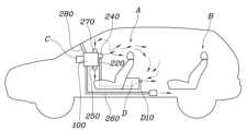
도 5는 본 발명의 일 실시예에 따른 차량의 공기조화장치의 구성도이고, 도 1 내지 4의 경우 각각의 모드에 따른 작동을 나타낸 도면이다. 본 발명에 따른 차량의 공기조화장치는, 공기유입구(120)와 공기유출구(140)가 형성되며, 공기유입구(120)와 공기유출구(140)의 사이에 냉각코어(160)와 히팅코어(170)가 구비된 하우징(100); 일단이 하우징(100)의 공기유출구(140)와 연결되며, 차량의 후방으로 연장되고, 타단이 후석(B)공간을 향하도록 배치된 후석공기벤트(D10)와 연결된 리어연장유로(220); 리어연장유로(220)와 하우징(100)의 공기유입구(120)를 직접 연결하는 공기회수유로(230); 및 리어연장유로(220)와 공기유출구(140) 사이의 공기유통 및 공기회수유로(230)와 공기유입구(120) 사이의 공기유통을 개폐하는 개폐도어유닛(300);을 포함한다.Figure 5 is a configuration diagram of a vehicle air conditioning system according to an embodiment of the present invention, and Figures 1 to 4 are diagrams showing operation according to each mode. The air conditioning device for a vehicle according to the present invention is formed with an
하우징(100)은 차량에 설치되어 공기를 도입하고, 도입된 공기를 냉각하거나 히팅하거나 믹싱한 후 각각의 유로를 통해 토출하는 역할을 수행한다. 그리고 내부에는 블로워(150)가 마련되어 공기 흐름을 위한 동력을 제공한다. 또한, 필터(130)가 마련되어 도입된 공기를 정화한 후 실내로 토출하도록 한다.The
구체적으로, 본 발명의 하우징(100)은 공기유입구(120)와 공기유출구(140)가 형성되며, 공기유입구(120)와 공기유출구(140)의 사이에 냉각코어(160)와 히팅코어(170)가 구비된다. 그리고 차량은 전석(A)과 후석(B)으로 공간이 구비되고, 그에 따라 각각 시트가 설치되는데, 전석(A)과 후석(B)의 경우 상대적인 전후 배치 순서를 따라 정해질 수 있고, 후석(B)이 여러 열로 마련될 수도 있다. 또한, 내연기관 차량의 경우에는 뜨거워진 엔진 냉각수로 히팅코어(170)를 가열하지만, 전기자동차 등의 경우에는 별도의 전열기구가 히팅코어(170)가 되거나 전열기구를 이용하여 간적접으로 히팅코어(170)를 가열하는 것도 가능하고, 냉매를 활용한 히트펌프시스템 등을 이용하여 히팅코어(170)를 가열하는 등의 다양한 방법이 활용될 수 있다.Specifically, the
한편, 전석(A)의 경우에는 차량 전방의 센터페시아에서 바로 공기를 토출하여 냉방을 수행하고, 전석(A)의 플로어측을 향해 공기를 토출하여 난방을 수행한다.Meanwhile, in the case of the front seats (A), air is discharged directly from the center fascia at the front of the vehicle to perform cooling, and air is discharged toward the floor side of the front seats (A) to perform heating.
그리고 후석(B)의 경우 냉방시에는 센터터널을 따라 연장되어 센터콘솔(D)로 향하는 리어연장유로(220)를 통해 후방으로 공기를 토출하여 냉방하고, 난방시에는 플로어를 따라 후방으로 연장된 플로어유로(260)를 통해 후석 바닥으로 공기를 토출하여 난방을 한다.In the case of the rear seat (B), when cooling, air is discharged to the rear through the
리어연장유로(220)는 일단이 하우징(100)의 공기유출구(140)와 연결되며, 차량의 후방으로 연장되고, 타단이 후석공간을 향하도록 배치된 후석공기벤트(D10)와 연결된다. 구체적으로, 후석공기벤트(D10)는 전석(A)과 후석(B) 사이의 센터콘솔(D)에 마련되고, 리어연장유로(220)는 차량의 플로어를 따라 연장되어 센터콘솔(D)에서 후석공기벤트(D10)와 연결될 수 있다. 리어연장유로(220)는 하우징(100)에서 연장되는 별도의 덕트 구조일 수 있다.The
그리고 공기회수유로(230)는 리어연장유로(220)와 하우징(100)의 공기유입구(120)를 직접 연결하도록 한다. 또한, 리어연장유로(220)와 공기유출구(140) 사이의 공기유통 및 공기회수유로(230)와 공기유입구(120) 사이의 공기유통을 개폐하는 개폐도어유닛(300)이 마련된다. 공기회수유로(230)는 하우징(100)의 내부에도 마련될 수 있고 하우징의 외부에도 마련될 수 있다. 공기회수유로(230)가 차량의 공조장치(HVAC : heating, ventilation, & air conditioning) 내부에 마련되는 경우에는 차량의 공조장치 하우징의 내부에 형성된 다양한 유로들과 마찬가지로 하우징에 일체로서 성형될 수 있다.And the
이러한 유로들의 연결구조를 통해 전석 센터페시아에서 토출된 차가운 공기가 전석(A)을 냉방한 후 후방에서 센터콘솔(D)의 후석공기벤트(D10) - 리어연장유로(220) - 공기회수유로(230) 순으로 다시 유입되어 하우징(100) 내부에서 재공조된 후 다시 토출되는바, 냉방 효율이 매우 높아진다. 종래의 차량에도 대부분 내기순환을 위한 구조가 있었지만, 이러한 구조들은 센터페시아에 있는 것이 보통이어서, 후방으로 토출되는 공기를 재도입한다기보다는 실내의 전방에 머무르는 공기를 재도입하는 수준이었고, 재순환의 효율이 매우 떨어졌다.Through the connection structure of these channels, the cold air discharged from the front seat center fascia cools the front seats (A) and then flows from the rear to the rear seat air vent (D10) of the center console (D) - rear extension passage (220) - air recovery passage ( 230), it is re-introduced, re-conditioned inside the
특히 차량의 전석(A)에만 탑승자가 앉아 있는 경우에는 차량 후석(B)의 경우 공조가 불필요하기 때문에 본 발명의 구조에 따를 경우 차가운 공기가 도 5와 같이 전석(A)에서만 순환되는 루프를 이룰 수 있어 에너지 차원에서 매우 효과적이다.In particular, when the occupants sit only in the front seat (A) of the vehicle, air conditioning is not necessary in the rear seat (B) of the vehicle, so according to the structure of the present invention, a loop is formed in which cold air circulates only in the front seat (A) as shown in FIG. 5. It is very effective in terms of energy.
이를 위해, 공기회수유로(230)는 일단이 리어연장유로(220)의 일단측에 연결되고 타단이 하우징(100)의 공기유입구(120)와 연결될 수 있다. 그리고 공기회수유로(230)는 타단이 하우징(100) 공기유입구(120)측에 형성된 내기도입부(270)에 연결될 수 있다. 이를 통해 리어연장유로(220)는 후방으로 공기를 토출하거나 또는 후방에서 공기를 도입하는 두 가지의 역할을 선택적으로 수행하게 된다.For this purpose, one end of the
하우징(100) 공기유입구(120)측에는 내기도입부(270)와 외기도입부(280)가 형성되고, 하우징(100) 내부공간에는 공기유입구(120)측으로 공기필터(130)가 마련되며, 내기도입부(270) 및 외기도입부(280)가 형성된 지점과 공기필터(130) 사이에는 이격 공간이 형성되고, 공기회수유로(230)는 이격공간에 연결됨으로써 리어연장유로(220)와 하우징(100)의 공기유입구(120)를 직접 연결할 수 있다. 이를 통하여 종래에 적용되어 있는 공조장치 하우징에도 쉽게 본 발명을 적용하는 것이 가능하다. 본래부터 있던 공간을 활용하고 유로 1개와 도어 1개만을 추가함으로써 큰 설계변경 없이도 쉽게 구현이 가능한 것이다.An
한편, 개폐도어유닛(300)은 리어연장유로(220)에 마련되어 리어연장유로(220)와 공기유출구(140) 사이의 공기유통을 개폐하는 후석공조도어(320) 및 공기회수유로(230)에 마련되어 공기회수유로(230)와 공기유입구(120) 사이의 공기유통을 개폐하는 공기회수도어(340)로 구성될 수 있다.Meanwhile, the opening/
구체적으로, 후석공조도어(320)는 리어연장유로(220)에서 공기회수유로(230)가 연결되는 지점보다 상류측에 마련될 수 있다. 이를 통하여 리어연장유로(220)가 확실히 후방으로 공기를 토출하거나 또는 후방에서 공기를 도입하는 두 가지의 역할을 구분하여 수행하게 된다.Specifically, the rear
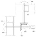
그리고, 도 6과 같이, 공기회수도어(340)와 후석공조도어(320)는 동력전달구조체(360)로 연결되어 연동되며, 이 경우 액추에이터(380)를 1개만 사용함으로써 공기회수도어(340)의 개방작동시 후석공조도어(320)는 폐쇄작동되고, 공기회수도어(340)의 폐쇄작동시 후석공조도어(320)는 개방작동될 수 있다. 물론, 각각의 도어에 각각 액추에이터를 적용하여 개별적으로 제어하는 것도 가능할 것이다.And, as shown in Figure 6, the
제어기(C)는 각종 도어의 작동을 제어함으로써 다양한 공조모드를 구현하도록 한다. 구체적으로, 도 2는 본 발명의 일 실시예에 따른 차량의 공기조화장치의 후석냉방모드인 경우를 나타낸 도면이고, 도 4는 본 발명의 일 실시예에 따른 차량의 공기조화장치의 후석난방모드인 경우를 나타낸 도면이다.The controller (C) implements various air conditioning modes by controlling the operation of various doors. Specifically, Figure 2 is a diagram showing the rear seat cooling mode of the air conditioning system of a vehicle according to an embodiment of the present invention, and Figure 4 is a diagram showing the rear seat heating mode of the air conditioning system of a vehicle according to an embodiment of the present invention. This is a drawing showing the case.
후석공조모드시에는 제어기(C)가 리어연장유로(220)와 공기유출구(140) 사이의 공기유통이 개방되도록 하고, 공기회수모드시에는 공기회수유로(230)와 공기유입구(120) 사이의 공기유통이 개방되도록 개폐도어유닛(300)을 제어한다. 이를 위해 제어기(C)는 후석공조모드시 공기회수유로(230)와 공기유입구(120) 사이의 공기유통이 폐쇄되도록 하고, 공기회수모드시 리어연장유로(220)와 공기유출구(140) 사이의 공기유통이 폐쇄되도록 개폐도어유닛(300)을 제어할 수 있다.In the rear seat air conditioning mode, the controller (C) opens the air circulation between the
즉, 도 2와 같이 후석냉방모드인 경우에는 후석공조도어(320)를 개방하여 냉각된 공기가 리어연장유로(220)로 공급되도록 하고 이 경우에는 공기회수도어(340)를 폐쇄하여 후석의 공기를 다시 전방으로 유입하지 않도록 함으로써 후석 탑승자도 쾌적해질 수 있도록 한다. 한편, 도 4와 같이 후석난방모드인 경우에는 가열된 공기가 플로어유로(260)를 통해 후석의 바닥으로 공급되도록 한다. 이 경우 후석공조도어(320)는 폐쇄하여 리어연장유로(220)로 가열된 공기가 가지 않도록 함으로써 후석 탑승자의 불쾌감을 줄인다. 그리고 공기회수도어(340)는 폐쇄하여 후석 탑승자가 온기를 충분히 느낄 수 있도록 한다. 물론, 에너지 효율차원에서 이 경우 공기회수도어(340)를 개방하여 재순환함으로서 효율을 높이는 것도 가능할 것이다.That is, in the case of rear seat cooling mode as shown in FIG. 2, the rear seat
한편, 도 1과 같이 전석냉방모드인 경우에는 앞서 설명한 것과 같이 후석공조도어(320)를 폐쇄하고 공기회수도어(340)를 개방하여 전방에서 후방을 향해 토출된 냉기가 전석(A)을 공조한 후 바로 다시 유입되어 리어연장유로(220)를 통해 전방으로 도입된 후 재공조되어 재토출되도록 함으로써 에너지를 효과적으로 사용하고 전석 탑승자의 쾌적감을 최대한 끌어올리도록 한다. 그리고 도 3과 같이 전석난방모드인 경우에도 후석공조도어(320)를 폐쇄하고 공기회수도어(340)를 개방하여 전석(A)만을 따뜻하게 함으로써 에너지를 절약할 수 있도록 한다.Meanwhile, in the case of the front seat cooling mode as shown in FIG. 1, the rear seat
그리고, 제어기(C)는 후석승객이 감지된 경우 후석공조모드를 구현하고, 후석승객이 감지되지 않은 경우 공기회수모드를 구현함으로써 자동적으로 최적의 제어를 수행하도록 할 수 있고, 여기서 후석의 탑승을 센싱함에 있어서는 카메라, 정전용량, 무게센서 등 다양한 방식의 센서 사용이 가능하다.In addition, the controller (C) can automatically perform optimal control by implementing a rear-seat air conditioning mode when a rear-seat passenger is detected and an air recovery mode when a rear-seat passenger is not detected, where boarding of the rear seat is possible. For sensing, various types of sensors can be used, such as cameras, capacitance, and weight sensors.
특히, 제어기(C)는 디프로스트모드시 공기회수유로(230)와 공기유입구(120) 사이의 공기유통이 폐쇄되도록 개폐도어유닛(300)을 제어함으로써 차량 운행의 안전을 해하지 않는 범위에서 에너지를 절감할 수 있다. 보통 겨울에는 따뜻하고 습한 실내공기가 차가운 윈드실드에 응축되어 윈드실드의 시야가 가려지는 현상이 발생하는데, 이를 제거하기 위해 제어기(C)는 디프로스트모드를 구현한다. 이 경우에는 차량의 습한 내기를 사용하지 않고 외기를 사용함이 일반적인바, 외기를 가열하여 윈드실드측으로 토출한다. 따라서, 이 경우에는 내기의 순환이 불필요한바, 디프로스트모드시 공기회수유로(230)와 공기유입구(120) 사이의 공기유통이 폐쇄되도록 개폐도어유닛(300)을 제어하는 것이다.In particular, the controller (C) controls the opening/
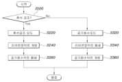
도 7은 본 발명의 일 실시예에 따른 차량의 공기조화장치 제어방법의 순서도로서, 본 발명의 차량의 공기조화장치 제어방법은, 공조제어모드를 판단하는 단계(S100); 공조제어모드가 후석공조모드인 경우, 후석공기벤트와 연결된 리어연장유로와 공기유출구 사이의 공기유통이 개방되도록 개폐도어유닛을 제어함으로써 공조된 공기가 후석공기벤트를 통해 토출되도록 하는 단계(S220,S240); 및 공조제어모드가 공기회수모드인 경우, 리어연장유로에 연결된 공기회수유로와 공기유입구 사이의 공기유통이 개방되도록 개폐도어유닛을 제어함으로써 후석공기벤트를 통해 하우징으로 내기를 도입하는 단계(S320,S340);를 포함한다. 공기회수모드란, 전석만을 공조하기 때문에 공기를 회수하는 경우를 말한다.Figure 7 is a flow chart of a method of controlling an air conditioning system of a vehicle according to an embodiment of the present invention. The method of controlling an air conditioning system of a vehicle of the present invention includes the step of determining an air conditioning control mode (S100); When the air conditioning control mode is the rear seat air conditioning mode, a step (S220, S240); And when the air conditioning control mode is the air recovery mode, introducing air into the housing through the rear seat air vent by controlling the opening/closing door unit to open the air circulation between the air recovery passage connected to the rear extension passage and the air inlet (S320, S340); includes. The air recovery mode refers to a case where air is recovered because only all seats are air-conditioned.
그리고 공조된 공기가 후석공기벤트를 통해 토출되도록 하는 단계(S220)에서는 공기회수유로와 공기유입구 사이의 공기유통이 폐쇄되도록 제어기를 통해 개폐도어유닛을 제어하고(S260), 후석공기벤트를 통해 하우징으로 내기를 도입하는 단계(S320)에서는 리어연장유로와 공기유출구 사이의 공기유통이 폐쇄되도록 개폐도어유닛을 제어할 수 있다(S360).And in the step of discharging the conditioned air through the rear seat air vent (S220), the opening/closing door unit is controlled through a controller to close the air circulation between the air recovery passage and the air inlet (S260), and the housing is opened through the rear seat air vent. In the step of introducing a bet (S320), the opening/closing door unit can be controlled so that the air circulation between the rear extension passage and the air outlet is closed (S360).
본 발명의 차량의 공기조화장치 및 그 제어방법에 따르면, 후석 공조 기능을 사용하지 않을 경우 전석에서 토출된 공기를 다시 후방에서 도입하여 재순환함으로써 공조된 공기를 충분히 사용 후 재도입할 수 있는 효과가 있다.According to the vehicle air conditioning device and its control method of the present invention, when the rear seat air conditioning function is not used, the air discharged from the front seat is re-introduced from the rear and recirculated, resulting in the effect of reintroducing the conditioned air after sufficient use. there is.
본 발명에 따르면, 전방에서 후방을 향해 토출된 공기를 전방이 아닌 후방에서 유입함으로써 토출된 공조공기를 최대한 재유입하고 재순환함으로써 에너지 효율이 매우 높아진다.According to the present invention, the air discharged from the front to the rear is introduced from the rear rather than the front, thereby re-introducing and recirculating the discharged air conditioning air as much as possible, greatly increasing energy efficiency.
본 발명의 특정한 실시예에 관련하여 도시하고 설명하였지만, 이하의 특허청구범위에 의해 제공되는 본 발명의 기술적 사상을 벗어나지 않는 한도 내에서, 본 발명이 다양하게 개량 및 변화될 수 있다는 것은 당 업계에서 통상의 지식을 가진 자에게 있어서 자명할 것이다.Although the present invention has been shown and described in relation to specific embodiments, it is known in the art that the present invention can be modified and changed in various ways without departing from the technical spirit of the present invention as provided by the following claims. It will be self-evident to those with ordinary knowledge.
100 : 하우징 220 : 리어연장유로
230 : 공기회수유로 300 : 개폐도어유닛
C : 제어기100: Housing 220: Rear extension passage
230: Air recovery passage 300: Opening/closing door unit
C: controller
Claims (15)
Translated fromKorean일단이 하우징의 공기유출구와 연결되며, 차량의 후방으로 연장되고, 타단이 후석공간을 향하도록 배치된 후석공기벤트와 연결된 리어연장유로;
리어연장유로와 하우징의 공기유입구를 직접 연결하는 공기회수유로; 및
후석승객이 감지된 경우 후석공조모드가 수행되고, 후석승객이 감지되지 않은 경우 공기회수모드가 수행되는 공조제어모드에 따라 리어연장유로와 공기유출구 사이의 공기유통 및 공기회수유로와 공기유입구 사이의 공기유통을 개폐하는 개폐도어유닛;을 포함하되,
후석공기벤트는 차량의 전석과 후석 사이의 센터콘솔에 마련되며,
공기회수유로는 일단이 리어연장유로의 일단측에 연결되고, 타단이 하우징의 공기유입구 측에 형성된 내기도입부로부터 이격된 위치에서 하우징의 공기유입구와 연결되며,
공기회수모드시에는 공기회수유로와 공기유입구 사이의 공기유통이 개방되도록 하여 공기유출구를 통해 공기가 토출되고, 후석공기벤트를 통해 하우징으로 토출된 공기가 도입되는 것을 특징으로 하는 차량의 공기조화장치.A housing formed with an air inlet and an air outlet, and having a cooling core and a heating core between the air inlet and the air outlet;
A rear extension passageway whose end is connected to the air outlet of the housing, extends to the rear of the vehicle, and whose other end is connected to the rear seat air vent arranged to face the rear seat space;
An air recovery passage directly connecting the rear extension passage and the air inlet of the housing; and
Depending on the air conditioning control mode, when rear seat passengers are detected, the rear seat air conditioning mode is performed, and when rear seat passengers are not detected, the air recovery mode is performed. Air distribution between the rear extension passage and the air outlet, and between the air recovery passage and the air inlet, are controlled according to the air conditioning control mode. Including an opening and closing door unit that opens and closes the air distribution,
The rear seat air vent is located in the center console between the front and rear seats of the vehicle.
One end of the air recovery passage is connected to one side of the rear extension passage, and the other end is connected to the air inlet of the housing at a position spaced apart from the internal inlet formed on the air inlet side of the housing,
In the air recovery mode, the air circulation between the air recovery passage and the air inlet is opened so that air is discharged through the air outlet, and the discharged air is introduced into the housing through the rear seat air vent. .
개폐도어유닛은 리어연장유로에 마련되어 리어연장유로와 공기유출구 사이의 공기유통을 개폐하는 후석공조도어 및 공기회수유로에 마련되어 공기회수유로와 공기유입구 사이의 공기유통을 개폐하는 공기회수도어로 구성된 것을 특징으로 하는 차량의 공기조화장치.In claim 1,
The opening/closing door unit consists of a rear air conditioning door provided in the rear extension passage to open and close the air distribution between the rear extension passage and the air outlet, and an air recovery door provided in the air recovery passage to open and close the air distribution between the air recovery passage and the air inlet. Characterized by a vehicle air conditioning system.
후석공조도어는 리어연장유로에서 공기회수유로가 연결되는 지점보다 상류측에 마련된 것을 특징으로 하는 차량의 공기조화장치.In claim 4,
The rear air conditioning door is an air conditioning device for a vehicle, characterized in that it is provided upstream of the point where the air recovery passage is connected to the rear extension passage.
공기회수도어와 후석공조도어는 동력전달구조체로 연결되어 연동되며, 공기회수도어의 개방작동시 후석공조도어는 폐쇄작동되고, 공기회수도어의 폐쇄작동시 후석공조도어는 개방작동되는 것을 특징으로 하는 차량의 공기조화장치.In claim 4,
The air recovery door and the rear air conditioning door are connected and interlocked by a power transmission structure, and when the air recovery door is opened, the rear air conditioning door is closed, and when the air recovery door is closed, the rear air conditioning door is opened. Vehicle air conditioning system.
후석공조모드시에는 리어연장유로와 공기유출구 사이의 공기유통이 개방되도록 하고, 공기회수모드시에는 공기회수유로와 공기유입구 사이의 공기유통이 개방되도록 개폐도어유닛을 제어하는 제어기;를 더 포함하는 것을 특징으로 하는 차량의 공기조화장치.In claim 1,
A controller that controls the opening/closing door unit to open the air circulation between the rear extension passage and the air outlet in the rear seat air conditioning mode, and to open the air circulation between the air recovery passage and the air inlet in the air recovery mode. An air conditioning device for a vehicle, characterized in that.
제어기는 후석공조모드시 공기회수유로와 공기유입구 사이의 공기유통이 폐쇄되도록 하고, 공기회수모드시 리어연장유로와 공기유출구 사이의 공기유통이 폐쇄되도록 개폐도어유닛을 제어하는 것을 특징으로 하는 차량의 공기조화장치.In claim 7,
The controller controls the opening/closing door unit to close the air circulation between the air recovery passage and the air inlet in the rear seat air conditioning mode, and to close the air circulation between the rear extension passage and the air outlet in the air recovery mode. Air conditioning device.
제어기는 후석승객이 감지된 경우 후석공조모드를 구현하고, 후석승객이 감지되지 않은 경우 공기회수모드를 구현하는 것을 특징으로 하는 차량의 공기조화장치.In claim 7,
An air conditioning device for a vehicle, wherein the controller implements a rear-seat air conditioning mode when a rear-seat passenger is detected and an air recovery mode when a rear-seat passenger is not detected.
제어기는 디프로스트모드시 공기회수유로와 공기유입구 사이의 공기유통이 폐쇄되도록 개폐도어유닛을 제어하는 것을 특징으로 하는 차량의 공기조화장치.In claim 7,
An air conditioning device for a vehicle, wherein the controller controls the opening/closing door unit to close the air circulation between the air recovery passage and the air inlet in the defrost mode.
하우징 공기유입구측에는 내기도입부와 외기도입부가 형성되고, 하우징 내부공간에는 공기유입구측으로 공기필터가 마련되며, 내기도입부 및 외기도입부가 형성된 지점과 공기필터 사이에는 이격 공간이 형성되고, 공기회수유로는 이격공간에 연결됨으로써 리어연장유로와 하우징의 공기유입구를 직접 연결하는 것을 특징으로 하는 차량의 공기조화장치.In claim 1,
An internal air inlet part and an external air inlet part are formed on the housing air inlet side, and an air filter is provided on the air inlet side in the inner space of the housing. A separation space is formed between the point where the internal air inlet part and the external air inlet part are formed and the air filter, and the air recovery flow path is separated. An air conditioning device for a vehicle, characterized in that it directly connects the rear extension passage and the air inlet of the housing by being connected to the space.
리어연장유로는 차량의 플로어에서 연장되어 센터콘솔에서 후석공기벤트와 연결된 것을 특징으로 하는 차량의 공기조화장치.In claim 1,
The rear extension passage is an air conditioning device for a vehicle, characterized in that it extends from the floor of the vehicle and is connected to the rear seat air vent in the center console.
후석공조모드이며 동시에 난방모드인 경우 리어연장유로와 공기유출구 사이의 공기유통 및 공기회수유로와 공기유입구 사이의 공기유통이 폐쇄되도록 개폐도어유닛을 제어하는 제어기;를 더 포함하는 것을 특징으로 하는 차량의 공기조화장치.In claim 1,
The vehicle further includes a controller that controls the opening/closing door unit to close the air distribution between the rear extension passage and the air outlet and the air distribution between the air recovery passage and the air inlet when the rear seat air conditioning mode is in the heating mode at the same time. air conditioning equipment.
공조제어모드가 후석공조모드인 경우, 차량의 전석과 후석 사이의 센터콘솔에 마련된 후석공기벤트와 연결된 리어연장유로와 공기유출구 사이의 공기유통이 개방되도록 개폐도어유닛을 제어함으로써 공조된 공기가 후석공기벤트를 통해 토출되도록 하는 단계; 및
공조제어모드가 공기회수모드인 경우, 일단이 리어연장유로의 일단측에 연결되고, 타단이 하우징의 공기유입구 측에 형성된 내기도입부로부터 이격된 위치에서 하우징의 공기유입구와 연결된 공기회수유로와 공기유입구 사이의 공기유통이 개방되도록 개폐도어유닛을 제어함으로써 공기유출구를 통해 공기가 토출되도록 하고, 후석공기벤트를 통해 토출된 공기가 하우징으로 도입되도록 하는 단계;를 포함하는 차량의 공기조화장치 제어방법.Determining the air conditioning control mode;
When the air conditioning control mode is the rear seat air conditioning mode, the air conditioned air is directed to the rear seat by controlling the opening/closing door unit to open the air circulation between the rear extension passage connected to the rear air vent provided in the center console between the front and rear seats of the vehicle and the air outlet. allowing discharge through an air vent; and
When the air conditioning control mode is the air recovery mode, the air recovery passage and air inlet have one end connected to one end of the rear extension passage and the other end connected to the air inlet of the housing at a distance away from the internal inlet formed on the air inlet side of the housing. A method of controlling an air conditioning system for a vehicle, including the step of controlling the opening/closing door unit to open the air circulation between the doors so that air is discharged through the air outlet, and allowing the air discharged through the rear seat air vent to be introduced into the housing.
공조된 공기가 후석공기벤트를 통해 토출되도록 하는 단계에서는 공기회수유로와 공기유입구 사이의 공기유통이 폐쇄되도록 개폐도어유닛을 제어하고, 후석공기벤트를 통해 하우징으로 내기를 도입하는 단계에서는 리어연장유로와 공기유출구 사이의 공기유통이 폐쇄되도록 개폐도어유닛을 제어하는 것을 특징으로 하는 차량의 공기조화장치 제어방법.In claim 14,
In the step of discharging the conditioned air through the rear seat air vent, the opening/closing door unit is controlled to close the air circulation between the air recovery passage and the air inlet, and in the step of introducing air into the housing through the rear seat air vent, the rear extension passage is controlled. A method of controlling an air conditioning system for a vehicle, characterized in that the opening and closing door unit is controlled to close the air circulation between the air outlet and the air outlet.
Priority Applications (2)
| Application Number | Priority Date | Filing Date | Title |
|---|---|---|---|
| KR1020180129138AKR102663207B1 (en) | 2018-10-26 | 2018-10-26 | Apparatus for air-ventilation of vehicle and method for controlling the same |
| US16/269,008US11465465B2 (en) | 2018-10-26 | 2019-02-06 | Air ventilation device of vehicle and method for controlling the same |
Applications Claiming Priority (1)
| Application Number | Priority Date | Filing Date | Title |
|---|---|---|---|
| KR1020180129138AKR102663207B1 (en) | 2018-10-26 | 2018-10-26 | Apparatus for air-ventilation of vehicle and method for controlling the same |
Publications (2)
| Publication Number | Publication Date |
|---|---|
| KR20200047931A KR20200047931A (en) | 2020-05-08 |
| KR102663207B1true KR102663207B1 (en) | 2024-05-03 |
Family
ID=70328592
Family Applications (1)
| Application Number | Title | Priority Date | Filing Date |
|---|---|---|---|
| KR1020180129138AActiveKR102663207B1 (en) | 2018-10-26 | 2018-10-26 | Apparatus for air-ventilation of vehicle and method for controlling the same |
Country Status (2)
| Country | Link |
|---|---|
| US (1) | US11465465B2 (en) |
| KR (1) | KR102663207B1 (en) |
Families Citing this family (2)
| Publication number | Priority date | Publication date | Assignee | Title |
|---|---|---|---|---|
| DE102019107613B3 (en)* | 2019-03-25 | 2020-07-02 | Bayerische Motoren Werke Aktiengesellschaft | Vehicle with an air conditioner that has a preconditioning operation |
| CN115199447B (en)* | 2022-06-07 | 2023-07-25 | 东风汽车集团股份有限公司 | Air inlet system of vehicle engine and control method thereof |
Citations (2)
| Publication number | Priority date | Publication date | Assignee | Title |
|---|---|---|---|---|
| JP2004114897A (en)* | 2002-09-27 | 2004-04-15 | Nissan Motor Co Ltd | Vehicle air conditioner |
| JP2011225117A (en)* | 2010-04-20 | 2011-11-10 | Nissan Motor Co Ltd | Air conditioning device for vehicle |
Family Cites Families (7)
| Publication number | Priority date | Publication date | Assignee | Title |
|---|---|---|---|---|
| JPH0930249A (en)* | 1995-07-21 | 1997-02-04 | Denso Corp | Air conditioner for vehicle |
| JP4293054B2 (en)* | 2003-09-26 | 2009-07-08 | 株式会社デンソー | Air conditioner for vehicles |
| KR102189136B1 (en) | 2014-03-11 | 2020-12-09 | 주식회사 두원공조 | Air conditioner for vehicle |
| JP6697815B2 (en)* | 2015-12-08 | 2020-05-27 | 三菱重工サーマルシステムズ株式会社 | Vehicle air conditioner |
| DE112017000155T5 (en)* | 2016-06-27 | 2018-06-21 | Hanon Systems | Air conditioning for one vehicle |
| US10759255B2 (en)* | 2016-07-20 | 2020-09-01 | Ford Global Technologies, Llc | Autonomous-vehicle climate-control system |
| US10829020B2 (en)* | 2018-02-01 | 2020-11-10 | Ford Global Technologies, Llc | Vehicle seating arrangement |
- 2018
- 2018-10-26KRKR1020180129138Apatent/KR102663207B1/enactiveActive
- 2019
- 2019-02-06USUS16/269,008patent/US11465465B2/enactiveActive
Patent Citations (2)
| Publication number | Priority date | Publication date | Assignee | Title |
|---|---|---|---|---|
| JP2004114897A (en)* | 2002-09-27 | 2004-04-15 | Nissan Motor Co Ltd | Vehicle air conditioner |
| JP2011225117A (en)* | 2010-04-20 | 2011-11-10 | Nissan Motor Co Ltd | Air conditioning device for vehicle |
Also Published As
| Publication number | Publication date |
|---|---|
| US20200130464A1 (en) | 2020-04-30 |
| US11465465B2 (en) | 2022-10-11 |
| KR20200047931A (en) | 2020-05-08 |
Similar Documents
| Publication | Publication Date | Title |
|---|---|---|
| KR100755951B1 (en) | Seat air conditioner for vehicle | |
| KR102603479B1 (en) | Air conditioner for vehicle | |
| KR20130133019A (en) | Air-conditioning device for vehicle | |
| KR102663207B1 (en) | Apparatus for air-ventilation of vehicle and method for controlling the same | |
| KR20180067761A (en) | Air conditioner for vehicles | |
| KR20210056227A (en) | Air conditioner for vehicle | |
| KR101946520B1 (en) | Air conditioning system for automotive vehicles | |
| KR101313598B1 (en) | Air conditioner in vehicle | |
| KR20190044893A (en) | Air conditioner for vehicle | |
| KR102533423B1 (en) | Air conditioner for vehicle | |
| KR102739698B1 (en) | Air conditioner for vehicle | |
| KR101364514B1 (en) | Air conditioner for an Automobile | |
| JP3912252B2 (en) | Parking ventilation or air conditioning | |
| JPH0413212Y2 (en) | ||
| KR101694041B1 (en) | An individual air conditioning apparatus with combined door for rear seat | |
| KR20090036370A (en) | Air Conditioning Device of Car Seat | |
| KR20180125687A (en) | Air conditioner for vehicle | |
| JPS6315043Y2 (en) | ||
| CN109986923A (en) | Automotive HVAC System | |
| KR20120134617A (en) | Air conditioner for vehicle | |
| KR101820789B1 (en) | Air conditioner for vehicle | |
| JPH044881Y2 (en) | ||
| KR101199683B1 (en) | Roof Duct for Rear Seat Air-conditioning of Vehicles | |
| KR100410941B1 (en) | Air conditioning apparatus for automobile | |
| KR20080104810A (en) | Car air conditioner |
Legal Events
| Date | Code | Title | Description |
|---|---|---|---|
| PA0109 | Patent application | Patent event code:PA01091R01D Comment text:Patent Application Patent event date:20181026 | |
| PG1501 | Laying open of application | ||
| A201 | Request for examination | ||
| PA0201 | Request for examination | Patent event code:PA02012R01D Patent event date:20211012 Comment text:Request for Examination of Application Patent event code:PA02011R01I Patent event date:20181026 Comment text:Patent Application | |
| E902 | Notification of reason for refusal | ||
| PE0902 | Notice of grounds for rejection | Comment text:Notification of reason for refusal Patent event date:20230725 Patent event code:PE09021S01D | |
| E701 | Decision to grant or registration of patent right | ||
| PE0701 | Decision of registration | Patent event code:PE07011S01D Comment text:Decision to Grant Registration Patent event date:20240130 | |
| GRNT | Written decision to grant | ||
| PR0701 | Registration of establishment | Comment text:Registration of Establishment Patent event date:20240429 Patent event code:PR07011E01D | |
| PR1002 | Payment of registration fee | Payment date:20240429 End annual number:3 Start annual number:1 | |
| PG1601 | Publication of registration |