KR102660343B1 - Front structure of vehicle body - Google Patents
Front structure of vehicle bodyDownload PDFInfo
- Publication number
- KR102660343B1 KR102660343B1KR1020190042692AKR20190042692AKR102660343B1KR 102660343 B1KR102660343 B1KR 102660343B1KR 1020190042692 AKR1020190042692 AKR 1020190042692AKR 20190042692 AKR20190042692 AKR 20190042692AKR 102660343 B1KR102660343 B1KR 102660343B1
- Authority
- KR
- South Korea
- Prior art keywords
- panel
- cowl panel
- vehicle
- cowl
- coupled
- Prior art date
- Legal status (The legal status is an assumption and is not a legal conclusion. Google has not performed a legal analysis and makes no representation as to the accuracy of the status listed.)
- Active
Links
- 239000011521glassSubstances0.000claimsabstractdescription39
- 230000035939shockEffects0.000claimsdescription22
- 239000006096absorbing agentSubstances0.000claimsdescription21
- 238000009434installationMethods0.000claimsdescription6
- 238000004378air conditioningMethods0.000claimsdescription3
- 230000000149penetrating effectEffects0.000claimsdescription3
- 238000010586diagramMethods0.000description7
- 238000000034methodMethods0.000description3
- 230000037147athletic performanceEffects0.000description1
- 230000005540biological transmissionEffects0.000description1
- 230000000694effectsEffects0.000description1
- 238000005516engineering processMethods0.000description1
- 239000000446fuelSubstances0.000description1
- 230000000644propagated effectEffects0.000description1
- 239000013589supplementSubstances0.000description1
Images


Classifications
- B—PERFORMING OPERATIONS; TRANSPORTING
- B62—LAND VEHICLES FOR TRAVELLING OTHERWISE THAN ON RAILS
- B62D—MOTOR VEHICLES; TRAILERS
- B62D25/00—Superstructure or monocoque structure sub-units; Parts or details thereof not otherwise provided for
- B62D25/08—Front or rear portions
- B62D25/088—Details of structures as upper supports for springs or dampers
- B—PERFORMING OPERATIONS; TRANSPORTING
- B62—LAND VEHICLES FOR TRAVELLING OTHERWISE THAN ON RAILS
- B62D—MOTOR VEHICLES; TRAILERS
- B62D25/00—Superstructure or monocoque structure sub-units; Parts or details thereof not otherwise provided for
- B62D25/08—Front or rear portions
- B—PERFORMING OPERATIONS; TRANSPORTING
- B62—LAND VEHICLES FOR TRAVELLING OTHERWISE THAN ON RAILS
- B62D—MOTOR VEHICLES; TRAILERS
- B62D25/00—Superstructure or monocoque structure sub-units; Parts or details thereof not otherwise provided for
- B62D25/08—Front or rear portions
- B62D25/081—Cowls
- B—PERFORMING OPERATIONS; TRANSPORTING
- B60—VEHICLES IN GENERAL
- B60S—SERVICING, CLEANING, REPAIRING, SUPPORTING, LIFTING, OR MANOEUVRING OF VEHICLES, NOT OTHERWISE PROVIDED FOR
- B60S1/00—Cleaning of vehicles
- B60S1/02—Cleaning windscreens, windows or optical devices
- B60S1/04—Wipers or the like, e.g. scrapers
- B60S1/043—Attachment of the wiper assembly to the vehicle
- B60S1/0438—Attachement of separate wiper motor assembly to the vehicle
- B—PERFORMING OPERATIONS; TRANSPORTING
- B62—LAND VEHICLES FOR TRAVELLING OTHERWISE THAN ON RAILS
- B62D—MOTOR VEHICLES; TRAILERS
- B62D21/00—Understructures, i.e. chassis frame on which a vehicle body may be mounted
- B62D21/11—Understructures, i.e. chassis frame on which a vehicle body may be mounted with resilient means for suspension, e.g. of wheels or engine; sub-frames for mounting engine or suspensions
- B—PERFORMING OPERATIONS; TRANSPORTING
- B62—LAND VEHICLES FOR TRAVELLING OTHERWISE THAN ON RAILS
- B62D—MOTOR VEHICLES; TRAILERS
- B62D25/00—Superstructure or monocoque structure sub-units; Parts or details thereof not otherwise provided for
- B62D25/02—Side panels
- B—PERFORMING OPERATIONS; TRANSPORTING
- B62—LAND VEHICLES FOR TRAVELLING OTHERWISE THAN ON RAILS
- B62D—MOTOR VEHICLES; TRAILERS
- B62D25/00—Superstructure or monocoque structure sub-units; Parts or details thereof not otherwise provided for
- B62D25/04—Door pillars ; windshield pillars
- B—PERFORMING OPERATIONS; TRANSPORTING
- B62—LAND VEHICLES FOR TRAVELLING OTHERWISE THAN ON RAILS
- B62D—MOTOR VEHICLES; TRAILERS
- B62D25/00—Superstructure or monocoque structure sub-units; Parts or details thereof not otherwise provided for
- B62D25/08—Front or rear portions
- B62D25/082—Engine compartments
- B—PERFORMING OPERATIONS; TRANSPORTING
- B62—LAND VEHICLES FOR TRAVELLING OTHERWISE THAN ON RAILS
- B62D—MOTOR VEHICLES; TRAILERS
- B62D25/00—Superstructure or monocoque structure sub-units; Parts or details thereof not otherwise provided for
- B62D25/08—Front or rear portions
- B62D25/14—Dashboards as superstructure sub-units
- B62D25/145—Dashboards as superstructure sub-units having a crossbeam incorporated therein
- B—PERFORMING OPERATIONS; TRANSPORTING
- B62—LAND VEHICLES FOR TRAVELLING OTHERWISE THAN ON RAILS
- B62D—MOTOR VEHICLES; TRAILERS
- B62D31/00—Superstructures for passenger vehicles
- B62D31/003—Superstructures for passenger vehicles compact cars, e.g. city cars
- B—PERFORMING OPERATIONS; TRANSPORTING
- B60—VEHICLES IN GENERAL
- B60S—SERVICING, CLEANING, REPAIRING, SUPPORTING, LIFTING, OR MANOEUVRING OF VEHICLES, NOT OTHERWISE PROVIDED FOR
- B60S1/00—Cleaning of vehicles
- B60S1/02—Cleaning windscreens, windows or optical devices
- B60S1/04—Wipers or the like, e.g. scrapers
- B60S1/0452—Position of the wipers relative to the vehicle
- B60S1/0458—Arrangement wherein the windscreen frame cooperates with the wipers
- B60S1/0463—Arrangement of the cowl
- B—PERFORMING OPERATIONS; TRANSPORTING
- B60—VEHICLES IN GENERAL
- B60Y—INDEXING SCHEME RELATING TO ASPECTS CROSS-CUTTING VEHICLE TECHNOLOGY
- B60Y2306/00—Other features of vehicle sub-units
- B60Y2306/01—Reducing damages in case of crash, e.g. by improving battery protection
Landscapes
- Engineering & Computer Science (AREA)
- Mechanical Engineering (AREA)
- Chemical & Material Sciences (AREA)
- Combustion & Propulsion (AREA)
- Transportation (AREA)
- Body Structure For Vehicles (AREA)
Abstract
Translated fromKoreanDescription
Translated fromKorean본 발명은 차량의 전방 오버행이 극단적으로 짧아지는 마이크로 모빌리티에 있어서 전방 오버행이 짧아지더라도 충돌강성을 확보하고 차량의 샤시 부품들 사이에 간섭이 없이 장착하며 차체의 강성과 마운팅부의 강성을 향상시킬 수 있도록 하는 차량의 차체 전방 구조체에 관한 것이다.The present invention can secure crash rigidity even when the front overhang is shortened in micro-mobility where the front overhang of the vehicle is extremely short, install without interference between vehicle chassis parts, and improve the rigidity of the vehicle body and the rigidity of the mounting part. It relates to the front body structure of a vehicle that allows
최근 자율주행차량과 전기자동차의 개발에 따라 이동수단으로서의 차량의 개념과 형태가 변화되고 있다. 이러한 수요자의 요구에 맞추어 소형의 이동수단으로서 마이크로 모빌리티가 개발되고 있는데, 마이크로 모빌리티의 경우 전기자동차로서 엔진이 없고, 그에 따라 불필요한 하중을 줄이고 연비를 높이기 위해 전방의 엔진룸이 대폭 축소되는 디자인 경향이 있다.Recently, with the development of autonomous vehicles and electric vehicles, the concept and form of vehicles as a means of transportation are changing. Micro-mobility is being developed as a small means of transportation in response to the needs of these consumers. In the case of micro-mobility, as an electric vehicle, there is no engine, and accordingly, the design trend is to drastically reduce the front engine room to reduce unnecessary load and increase fuel efficiency. there is.
엔진룸이 축소되는 경우에는 차량 전방의 구조체가 모두 짧아지고, 차량 전단과 전방 액슬의 중심 사이 거리인 전방 오버행 역시 극단적으로 줄일 수 있게 되어 차량 경량화와 운동성능의 가벼움을 추구할 수 있게 된다.When the engine room is reduced, all structures at the front of the vehicle are shortened, and the front overhang, which is the distance between the front end of the vehicle and the center of the front axle, can also be drastically reduced, making it possible to pursue lightness of vehicle weight and athletic performance.
그러나 이와 같이 전방 오버행이 극단적으로 짧아질 경우에는 전방 충돌시 충격량을 흡수할 수 있는 구조가 부족하고 충격량의 전달시간이 짧아져 실내공간으로 전달되는 충격이 증대된다. 따라서, 오버행을 줄이는 디자인을 채택하더라도 종래와 같은 수준의 충돌강성을 확보하기 위해서는 그에 맞추어 차체의 전방 구조가 변화할 필요가 있다.However, when the front overhang is extremely short like this, there is a lack of structure that can absorb the amount of impact in the event of a front collision, and the transmission time of the amount of impact is shortened, increasing the impact transmitted to the interior space. Therefore, even if a design that reduces the overhang is adopted, the front structure of the car body needs to change accordingly in order to secure the same level of crash rigidity as before.
상기의 배경기술로서 설명된 사항들은 본 발명의 배경에 대한 이해 증진을 위한 것일 뿐, 이 기술분야에서 통상의 지식을 가진자에게 이미 알려진 종래기술에 해당함을 인정하는 것으로 받아들여져서는 안 될 것이다.The matters described as background technology above are only for the purpose of improving understanding of the background of the present invention, and should not be taken as recognition that they correspond to prior art already known to those skilled in the art.
본 발명은 이러한 문제점을 해결하기 위하여 제안된 것으로, 차량의 전방 오버행이 극단적으로 짧아지는 마이크로 모빌리티에 있어서 전방 오버행이 짧아지더라도 충돌강성을 확보하고 차량의 샤시 부품들 사이에 간섭이 없이 장착하며 차체의 강성과 마운팅부의 강성을 향상시킬 수 있도록 하는 차량의 차체 전방 구조체를 제공하고자 함이다.The present invention was proposed to solve this problem, and in micro-mobility where the front overhang of the vehicle is extremely short, collision rigidity is secured even if the front overhang is short, and it is installed without interference between the vehicle chassis parts and the body of the vehicle. The purpose is to provide a front structure of the vehicle body that can improve the rigidity of the body and the rigidity of the mounting portion.
상기의 목적을 달성하기 위한 본 발명에 따른 차량의 차체 전방 구조체는, 차량의 폭 방향을 따라 연장된 패널 형상이고, 하단부가 대시패널의 상단부에 결합되며, 상단부가 차량의 전방으로 절곡되어 전방윈드실드글래스 하단의 후방 지점까지 연장된 제1카울패널; 및 차량의 폭 방향을 따라 연장된 패널 형상으로서 제1카울패널의 하방에 배치되며, 상단부가 전방으로 연장되어 전방윈드실드글래스의 하단에 결합되며, 하단부가 제1카울패널에 결합되고, 제1카울패널의 상단부가 결합됨으로써 제1카울패널과 함께 전방윈드실드글래스 하단의 후방 지점에서 차량 폭 방향으로 연장된 멤버를 형성하는 제2카울패널;을 포함한다.The front body structure of a vehicle according to the present invention for achieving the above object has a panel shape extending along the width direction of the vehicle, the lower end is coupled to the upper end of the dash panel, and the upper end is bent toward the front of the vehicle to provide front wind. A first cowl panel extending to the rear point at the bottom of the shield glass; and a panel shape extending along the width direction of the vehicle, disposed below the first cowl panel, the upper end extending forward and coupled to the lower end of the front windshield glass, the lower end being coupled to the first cowl panel, and the first cowl panel It includes a second cowl panel that is joined to the upper part of the cowl panel to form a member extending in the direction of the width of the vehicle at a rear point of the bottom of the front windshield glass together with the first cowl panel.
제1카울패널의 상단부는 제2카울패널의 중앙부에 결합되고, 제1카울패널의 중앙부와 제2카울패널의 중앙부 사이는 제1카울패널과 제2카울패널이 이격되어 멤버를 형성할 수 있다.The upper part of the first cowl panel is coupled to the central part of the second cowl panel, and the first cowl panel and the second cowl panel are spaced apart to form a member between the central part of the first cowl panel and the central part of the second cowl panel. .
제1카울패널의 일측에는 제2카울패널과 결합된 지점의 하부에 제1카울패널을 관통하는 블로워홀이 형성되고, 블로워홀은 공조장치에 차량의 외기를 도입할 수 있다.On one side of the first cowl panel, a blower hole penetrating the first cowl panel is formed at the bottom of the point where it is connected to the second cowl panel, and the blower hole can introduce outside air from the vehicle into the air conditioning system.
패널 형상이며, 상부가 전방윈드실드글래스를 따라 연장되고 하부가 대시패널을 따라 연장된 프런트필러이너패널;을 더 포함하고, 제1카울패널의 양단에는 차량의 전방을 향해 절곡된 제1플랜지가 형성되며 제2카울패널의 양단에는 차량의 전방을 향해 절곡된 제2플랜지가 형성되고, 프런트필러이너패널은 제1플랜지 및 제2플랜지를 통해 제1카울패널과 제2카울패널이 이루는 멤버 형상의 측단에 결합될 수 있다.It has a panel shape, and further includes a front pillar inner panel with the upper part extending along the front windshield glass and the lower part extending along the dash panel, and a first flange bent toward the front of the vehicle at both ends of the first cowl panel. A second flange is formed at both ends of the second cowl panel, bent toward the front of the vehicle, and the front pillar inner panel has a member shape formed by the first cowl panel and the second cowl panel through the first flange and the second flange. It can be joined to the side end of .
프런트필러이너패널은 환형의 패널 형상으로서 도어의 테두리를 따라 연장되고, 제1카울패널과 제2카울패널이 이루는 멤버 형상의 개방된 측단을 폐쇄하는 형상으로 결합될 수 있다.The front pillar inner panel has a ring-shaped panel shape, extends along the edge of the door, and can be combined in a shape that closes the open side end of the member shape formed by the first cowl panel and the second cowl panel.
전방윈드실드글래스 하단의 후방에 배치된 쇽업소버마운트;를 더 포함하고, 제2카울패널은 쇽업소버마운트의 상방에 배치될 수 있다.It may further include a shock absorber mount disposed at the rear of the bottom of the front windshield glass, and the second cowl panel may be disposed above the shock absorber mount.
쇽업소버마운트는 전방윈드실드글래스 하단의 후방에서 차량 양측으로 마련되고, 양측의 쇽업소버마운트는 크로스멤버에 의해 연결될 수 있다.Shock absorber mounts are provided on both sides of the vehicle at the rear at the bottom of the front windshield glass, and the shock absorber mounts on both sides can be connected by a cross member.
쇽업소버마운트 및 크로스멤버의 측단에는 휀더에이프런패널이 결합되고, 휀더에이프런패널의 후단은 프런트필러이너패널과 결합될 수 있다.A fender apron panel may be coupled to the side ends of the shock absorber mount and cross member, and the rear end of the fender apron panel may be coupled to the front pillar inner panel.
제2카울패널은 전방부가 실내공간측으로 만입되어 설치공간을 형성하고, 설치공간에 윈도우와이퍼 모터가 배치되며, 윈도우와이퍼 모터는 제2카울패널에 마운팅될 수 있다.The front part of the second cowl panel is recessed toward the interior space to form an installation space, a window wiper motor is disposed in the installation space, and the window wiper motor can be mounted on the second cowl panel.
윈도우와이퍼 모터는 제1카울패널과 제2카울패널이 이루는 멤버 형상에 직접 마운팅될 수 있다.The window wiper motor can be mounted directly on the member shape formed by the first cowl panel and the second cowl panel.
본 발명의 차량의 차체 전방 구조체에 따르면, 차량의 전방 오버행이 극단적으로 짧아지는 마이크로 모빌리티에 있어서 전방 오버행이 짧아지더라도 충돌강성을 확보하고 차량의 샤시 부품들 사이에 간섭이 없이 장착하며 차체의 강성과 마운팅부의 강성을 향상시킬 수 있게 된다.According to the vehicle body front structure of the present invention, in micro-mobility where the front overhang of the vehicle is extremely short, collision rigidity is secured even when the front overhang is short, and it is installed without interference between vehicle chassis parts, thereby improving the rigidity of the vehicle body. and the rigidity of the mounting part can be improved.
도 1은 본 발명의 일 실시예에 따른 차량의 차체 전방 구조체가 적용된 차량을 나타낸 도면.
도 2는 본 발명의 일 실시예에 따른 차량의 차체 전방 구조체의 단면도.
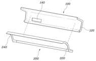
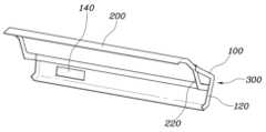
도 3은 본 발명의 일 실시예에 따른 차량의 차체 전방 구조체의 사시도.
도 4 내지 7은 본 발명의 일 실시예에 따른 차량의 차체 전방 구조체가 조립되는 과정을 나타낸 도면.
도 8은 본 발명의 일 실시예에 따른 차량의 차체 전방 구조체가 조립된 상태를 나타낸 도면.1 is a diagram showing a vehicle to which a front body structure of a vehicle according to an embodiment of the present invention is applied.
Figure 2 is a cross-sectional view of the front body structure of a vehicle according to an embodiment of the present invention.
Figure 3 is a perspective view of the front body structure of a vehicle according to an embodiment of the present invention.
4 to 7 are diagrams showing the process of assembling the front body structure of a vehicle according to an embodiment of the present invention.
Figure 8 is a diagram showing the assembled state of the front body structure of a vehicle according to an embodiment of the present invention.
도 1은 본 발명의 일 실시예에 따른 차량의 차체 전방 구조체가 적용된 차량을 나타낸 도면이고, 도 2는 본 발명의 일 실시예에 따른 차량의 차체 전방 구조체의 단면도이며, 도 3은 본 발명의 일 실시예에 따른 차량의 차체 전방 구조체의 사시도이고, 도 4 내지 7은 본 발명의 일 실시예에 따른 차량의 차체 전방 구조체가 조립되는 과정을 나타낸 도면이며, 도 8은 본 발명의 일 실시예에 따른 차량의 차체 전방 구조체가 조립된 상태를 나타낸 도면이다.FIG. 1 is a diagram showing a vehicle to which the front body structure of a vehicle according to an embodiment of the present invention is applied, FIG. 2 is a cross-sectional view of the front structure of a vehicle body according to an embodiment of the present invention, and FIG. 3 is a view showing a vehicle body front structure of a vehicle according to an embodiment of the present invention. It is a perspective view of the front body structure of a vehicle according to an embodiment, Figures 4 to 7 are diagrams showing the process of assembling the front structure of a vehicle body according to an embodiment of the present invention, and Figure 8 is an embodiment of the present invention. This is a drawing showing the assembled state of the vehicle body front structure according to .
도 1은 본 발명의 일 실시예에 따른 차량의 차체 전방 구조체가 적용된 차량을 나타낸 도면으로서, 도시된 바와 같이 본 발명이 적용될 경우 효과가 큰 차량은 전방 오버행(O)이 극단적으로 짧은 차량이다. 이러한 차량의 경우는 전기자동차로서 엔진이 없기 때문에 엔진룸이 불필요하고, 이동수단으로의 의미가 매우 강한 차량이다. 이같은 경우 엔진룸이 없기 때문에 프런트사이드멤버나 휀더 등의 경우도 매우 짧아 전방 충돌시 충분히 하중을 지지하지 못하고 로드패스를 형성하지 못함이 일반적이다.Figure 1 is a diagram illustrating a vehicle to which the front body structure of a vehicle according to an embodiment of the present invention is applied. As shown, a vehicle to which the present invention is applied to have a great effect is a vehicle with an extremely short front overhang (O). In the case of these vehicles, as they are electric vehicles and do not have an engine, an engine room is unnecessary, and they are very significant as a means of transportation. In this case, since there is no engine room, the front side members and fenders are also very short, so they are generally unable to sufficiently support the load and form a road path in the event of a frontal collision.
본 발명은 이와 같이 오버행이 짧은 차량의 경우에도 전방 구조를 변경함으로써 충돌하중을 견디고 로드패스를 잘 형성할 수 있도록 하기 위한 것이다. 도시된 차량의 경우에는 차량의 전방윈드실드글래스가 최전방까지 연장되고, 오버행은 매우 짧다. 따라서 전방 휠을 지지하는 쇽옵서버 마운팅 지점이 전방윈드실드글래스의 최하단보다 오히려 차량의 후방으로 치우친 지점에 위치될 수밖에 없다. 그에 따라 종래와 같은 카울의 형상은 찾아볼 수 없고 카울이 사라지는 경우에 해당할 수밖에 없다.The present invention is intended to enable vehicles with short overhangs to withstand collision loads and form a good road path by changing the front structure. In the case of the vehicle shown, the front windshield glass of the vehicle extends to the front, and the overhang is very short. Therefore, the shock absorber mounting point that supports the front wheels is bound to be located at a point toward the rear of the vehicle rather than at the bottom of the front windshield glass. Accordingly, the shape of the cowl as before cannot be found, and it is inevitable that the cowl will disappear.
이러한 구조를 구현하기 위해 본 발명에 따른 차량의 차체 전방 구조체는, 차량의 폭 방향을 따라 연장된 패널 형상이고, 하단부가 대시패널(D)의 상단부에 결합되며, 상단부가 차량의 전방으로 절곡되어 전방윈드실드글래스(W) 하단의 후방 지점까지 연장된 제1카울패널(100); 및 차량의 폭 방향을 따라 연장된 패널 형상으로서 제1카울패널(100)의 하방에 배치되며, 상단부가 전방으로 연장되어 전방윈드실드글래스(W)의 하단에 결합되며, 하단부가 제1카울패널(100)에 결합되고, 제1카울패널(100)의 상단부가 결합됨으로써 제1카울패널(100)과 함께 전방윈드실드글래스(W) 하단의 후방 지점에서 차량 폭 방향으로 연장된 멤버(300)를 형성하는 제2카울패널(200);을 포함한다.In order to implement this structure, the front body structure of the vehicle according to the present invention has a panel shape extending along the width direction of the vehicle, the lower end is coupled to the upper end of the dash panel (D), and the upper end is bent toward the front of the vehicle. A first cowl panel (100) extending to the rear point at the bottom of the front windshield glass (W); And it has a panel shape extending along the width direction of the vehicle and is disposed below the
도 2는 본 발명의 일 실시예에 따른 차량의 차체 전방 구조체의 단면도이고, 도 3은 본 발명의 일 실시예에 따른 차량의 차체 전방 구조체의 사시도이며, 도 4 내지 7은 본 발명의 일 실시예에 따른 차량의 차체 전방 구조체가 조립되는 과정을 나타낸 도면이고, 도 8은 조립된 상태를 나타낸다.Figure 2 is a cross-sectional view of the front body structure of a vehicle according to an embodiment of the present invention, Figure 3 is a perspective view of the front structure of the vehicle body according to an embodiment of the present invention, and Figures 4 to 7 are an embodiment of the present invention. This is a diagram showing the process of assembling the front body structure of a vehicle according to an example, and Figure 8 shows the assembled state.
도시된 바와 같이 본 발명의 카울은 기존과 같이 쇽업소버마운트(400)와 전방윈드실드글래스(W) 하단의 사이 공간을 채우는 구조가 아니라, 전방윈드실드글래스(W) 하단에서 오히려 후방부에 카울과 유사한 기능을 수행하는 구조가 마련된다. 이러한 카울 유사 구조는 제1카울패널(100)과 제2카울패널(200)의 조합으로 구성된다.As shown, the cowl of the present invention is not structured to fill the space between the
구체적으로, 제1카울패널(100)은 차량의 폭 방향을 따라 연장된 패널 형상이고, 하단부가 대시패널(D)의 상단부에 결합된다. 그리고 상단부가 차량의 전방으로 절곡되어 전방윈드실드글래스(W) 하단의 후방 지점까지 연장된다. 즉, 본 발명의 카울은 전방윈드실드글래스(W) 하단과 대시패널(D)의 사이에 존재한다. 그리고 제2카울패널(200)은 차량의 폭 방향을 따라 연장된 패널 형상으로서 제1카울패널(100)의 하방에 배치된다. 그리고 상단부가 전방으로 연장되어 전방윈드실드글래스(W)의 하단에 결합된다. 하단부는 제1카울패널(100)에 결합된다. 이에 따라 제2카울패널(200)은 제1카울패널(100)의 상단부가 결합됨으로써 제1카울패널(100)과 함께 전방윈드실드글래스(W) 하단의 후방 지점에서 차량 폭 방향으로 연장된 멤버(300)를 형성하도록 하는 것이다.Specifically, the
즉, 본 발명의 카울 유사구조는 제1카울패널(100)과 제2카울패널(200)의 결합에 의해 형성되며, 이러한 두 패널이 폐단면의 멤버(300) 형상을 구현함으로서 부족한 전방 충돌구조를 보완토록 한다. 그리고 멤버(300) 형상으로 형성함으로서 윈드실드글래스(W) 또는 와이퍼모터(W10) 등을 마운팅하더라도 조립강성을 효과적으로 확보할 수 있게 하는 것이다.In other words, the cowl-like structure of the present invention is formed by combining the
좀 더 구체적으로 살펴보면, 제1카울패널(100)의 상단부는 제2카울패널(200)의 중앙부에 결합되고, 제1카울패널(100)의 중앙부와 제2카울패널(200)의 중앙부 사이는 제1카울패널(100)과 제2카울패널(200)이 이격되어 멤버(300)를 형성할 수 있다.Looking more specifically, the upper part of the
그리고 제1카울패널(100)의 일측에는 제2카울패널(200)과 결합된 지점의 하부에 제1카울패널(100)을 관통하는 블로워홀(140)이 형성되고, 블로워홀(140)은 공조장치에 차량의 외기를 도입할 수 있다. 즉, 종래의 카울이 사라진 대신, 제1카울패널(100)에 블로워홀(140)을 형성함으로써 차량의 실내공간에 외기 도입이 가능해진다.And on one side of the
또한, 측방에는 프런트필러이너패널(700)이 마련되는데, 프런트필러이너패널(700)은 패널 형상이며, 상부가 전방윈드실드글래스(W)를 따라 연장되고 하부가 대시패널(D)을 따라 연장된다. 그리고 제1카울패널(100)의 양단에는 차량의 전방을 향해 절곡된 제1플랜지(120)가 형성되며 제2카울패널(200)의 양단에도 차량의 전방을 향해 절곡된 제2플랜지(220)가 형성된다. 이러한 프런트필러이너패널(700)은 제1플랜지(120) 및 제2플랜지(220)를 통해 제1카울패널(100)과 제2카울패널(200)이 이루는 멤버(300) 형상의 측단에 결합됨으로써 충돌시의 로드패스를 이루는 것이다.In addition, a front pillar
또한, 프런트필러이너패널(700)은 환형의 패널 형상으로서 도어의 테두리를 따라 연장된다. 도 7에 도시된 프런트필러이너패널(700)의 경우 후반부가 잘려진 형상으로 도시된 것이나, 프런트필러이너패널(700)은 도시된 것보다 후방으로 좀 더 연장되어 환형 내지 링형의 구조를 갖고 이는 도어의 테두리를 이루도록 한다. 이러한 프런트필러이너패널(700)의 전단부는 휀더에이프런패널(600)의 외측에 결합하며 제1카울패널(100)과 제2카울패널(200)이 이루는 멤버 형상의 개방된 측단을 폐쇄하는 형상으로 결합될 수 있다. 이러한 구조는 본 발명의 제1카울패널(100)과 제2카울패널(200)이 이루는 멤버(300) 형상에 연결되어 상호 로드패스를 형성하게 된다. 그리고 로드패스의 연속성을 확보하기 위해 멤버간에 면접촉이 이루어져야 하는바, 프런트필러이너패널(700)은 제1플랜지(120) 및 제2플랜지(220)를 통해 제1카울패널(100)과 제2카울패널(200)이 이루는 멤버(300) 형상의 측단에 결합되는 것이다. 도 8은 이와 같은 휀더에이프런패널(600)과 프런트필러이너패널(700)이 결합된 상태를 나타낸다.Additionally, the front pillar
한편, 전방윈드실드글래스(W) 하단의 후방에는 쇽업소버마운트(400)가 배치된다. 일반적인 차량의 경우와는 달리 오버행이 짧아 쇽업소버마운트(400)가 전방윈드실드글래스(W)보다 후방에 위치되는 것이다. 그리고 제2카울패널(200)은 쇽업소버마운트(400)의 상방에 배치될 수 있다.Meanwhile, a
또한, 쇽업소버마운트(400)는 전방윈드실드글래스(W) 하단의 후방에서 차량 양측으로 마련되고, 양측의 쇽업소버마운트(400)는 크로스멤버(500)에 의해 연결될 수 있다. 그리고 크로스멤버(500) 역시 도시된 바와 같이 휀더에이프런패널(600)에 연결된다. 따라서, 실질적으로 최전방에 위치되게 되는 크로스멤버(500)에 전달된 충돌하중은 쇽업소버마운트(400)를 통하여 휀더에이프런패널(600)과 프런트필러이너패널(700)를 통해 본 발명의 카울측의 멤버(300)로 분산되어 전파되는 로드패스를 형성하게 된다.In addition, shock absorber mounts 400 are provided on both sides of the vehicle at the rear of the bottom of the front windshield glass (W), and the shock absorber mounts 400 on both sides can be connected by a
또한, 크로스멤버(500)는 하방에 위치된 백빔멤버들과도 수직으로 연결됨으로서 충돌하중이 매우 다양한 경로로 분산되는 것이고, 이를 통하여 궁극적으로 오버행이 짧아지더라도 전방구조가 충격을 최대한 흡수하고, 실내공간으로 최소한의 충격만을 전달함으로써 시트측에 가해지는 최대 충격량의 피크치를 저감시키게 된다.In addition, the
그리고 제2카울패널(200)은 전방부가 실내공간측으로 만입되어 설치공간(240)을 형성하고, 설치공간(240)에 윈도우와이퍼 모터(W10)가 배치되며, 윈도우와이퍼 모터(W10)는 제2카울패널(200)에 마운팅될 수 있다. 이에 따라 도시된 바와 같이 윈도우와이퍼 모터(W10)는 제1카울패널(100)과 제2카울패널(200)이 이루는 멤버(300) 형상에 직접 마운팅될 수 있다. 기존의 경우에는 윈도우와이퍼 모터(W10)의 지지를 위해 카울에 별도의 브라켓 등을 두었으나, 본 발명의 경우에는 제1카울패널(100)과 제2카울패널(200)이 이루는 멤버(300) 형상의 폐단면 구조를 통한 강성 확보를 통하여, 윈도우와이퍼 모터(W10)의 마운팅을 강건하게 할 수 있게 되는 것이다.And the front part of the
본 발명의 차량의 차체 전방 구조체에 따르면, 차량의 전방 오버행이 극단적으로 짧아지는 마이크로 모빌리티에 있어서 전방 오버행이 짧아지더라도 충돌강성을 확보하고 차량의 샤시 부품들 사이에 간섭이 없이 장착하며 차체의 강성과 마운팅부의 강성을 향상시킬 수 있게 된다.According to the vehicle body front structure of the present invention, in micro-mobility where the front overhang of the vehicle is extremely short, collision rigidity is secured even when the front overhang is short, and it is installed without interference between vehicle chassis parts, thereby improving the rigidity of the vehicle body. and the rigidity of the mounting part can be improved.
본 발명의 특정한 실시예에 관련하여 도시하고 설명하였지만, 이하의 특허청구범위에 의해 제공되는 본 발명의 기술적 사상을 벗어나지 않는 한도 내에서, 본 발명이 다양하게 개량 및 변화될 수 있다는 것은 당 업계에서 통상의 지식을 가진 자에게 있어서 자명할 것이다.Although the present invention has been shown and described in relation to specific embodiments, it is known in the art that the present invention can be modified and changed in various ways without departing from the technical spirit of the present invention as provided by the following claims. This will be self-evident to those with ordinary knowledge.
100 : 제1카울패널 200 : 제2카울패널
300 : 멤버형상 400 : 쇽업소버마운트100: 1st cowl panel 200: 2nd cowl panel
300: Member shape 400: Shock absorber mount
Claims (12)
Translated fromKorean차량의 폭 방향을 따라 연장된 패널 형상으로서 제1카울패널의 하방에 배치되며, 상단부가 전방으로 연장되어 전방윈드실드글래스의 하단에 결합되며, 하단부가 제1카울패널에 결합되고, 제1카울패널의 상단부가 결합됨으로써 제1카울패널과 함께 전방윈드실드글래스 하단의 후방 지점에서 차량 폭 방향으로 연장된 멤버를 형성하는 제2카울패널을 포함하고;
제1카울패널의 일측에는 제2카울패널과 결합된 지점의 하부에 제1카울패널을 관통하는 블로워홀이 형성되고, 블로워홀은 공조장치에 차량의 외기를 도입하는 것을 특징으로 하는 차량의 차체 전방 구조체.A first cowl panel that has a panel shape extending along the width direction of the vehicle, the lower end of which is coupled to the upper end of the dash panel, and the upper end of which is bent toward the front of the vehicle and extends to a rear point at the bottom of the front windshield glass; and
It has a panel shape extending along the width direction of the vehicle and is disposed below the first cowl panel, the upper part extends forward and is coupled to the lower part of the front windshield glass, the lower part is coupled to the first cowl panel, and the first cowl panel It includes a second cowl panel that is joined to the upper part of the panel to form a member extending in the direction of the width of the vehicle at a rear point of the bottom of the front windshield glass together with the first cowl panel;
On one side of the first cowl panel, a blower hole penetrating the first cowl panel is formed at the lower part of the point where it is connected to the second cowl panel, and the blower hole introduces the outside air of the vehicle into the air conditioning system. anterior structure.
제1카울패널의 상단부는 제2카울패널의 중앙부에 결합되고, 제1카울패널의 중앙부와 제2카울패널의 중앙부 사이는 제1카울패널과 제2카울패널이 이격되어 멤버를 형성하는 것을 특징으로 하는 차량의 차체 전방 구조체.In claim 1,
The upper part of the first cowl panel is coupled to the central part of the second cowl panel, and the first cowl panel and the second cowl panel are spaced apart to form a member between the central part of the first cowl panel and the central part of the second cowl panel. The front body structure of a vehicle.
패널 형상이며, 상부가 전방윈드실드글래스를 따라 연장되고 하부가 대시패널을 따라 연장된 프런트필러이너패널;을 더 포함하고,
제1카울패널의 양단에는 차량의 전방을 향해 절곡된 제1플랜지가 형성되며 제2카울패널의 양단에는 차량의 전방을 향해 절곡된 제2플랜지가 형성되고, 프런트필러이너패널은 제1플랜지 및 제2플랜지를 통해 제1카울패널과 제2카울패널이 이루는 멤버 형상의 측단에 결합된 것을 특징으로 하는 차량의 차체 전방 구조체.In claim 1,
It further includes a front pillar inner panel that has a panel shape, the upper part extending along the front windshield glass and the lower part extending along the dash panel,
A first flange bent toward the front of the vehicle is formed at both ends of the first cowl panel, and a second flange bent toward the front of the vehicle is formed at both ends of the second cowl panel. The front pillar inner panel includes the first flange and the front pillar inner panel. A body front structure of a vehicle, characterized in that it is coupled to the side end of the member shape formed by the first cowl panel and the second cowl panel through a second flange.
프런트필러이너패널은 환형의 패널 형상으로서 도어의 테두리를 따라 연장되고, 제1카울패널과 제2카울패널이 이루는 멤버 형상의 개방된 측단을 폐쇄하는 형상으로 결합된 것을 특징으로 하는 차량의 차체 전방 구조체.In claim 4,
The front pillar inner panel has a ring-shaped panel shape, extends along the edge of the door, and is connected in a shape that closes the open side edge of the member shape formed by the first cowl panel and the second cowl panel. struct.
전방윈드실드글래스 하단의 후방에 배치된 쇽업소버마운트;를 더 포함하고,
제2카울패널은 쇽업소버마운트의 상방에 배치된 것을 특징으로 하는 차량의 차체 전방 구조체.In claim 1,
It further includes a shock absorber mount disposed at the rear of the bottom of the front windshield glass,
The second cowl panel is a front structure of the vehicle body, characterized in that it is disposed above the shock absorber mount.
쇽업소버마운트는 전방윈드실드글래스 하단의 후방에서 차량 양측으로 마련되고, 양측의 쇽업소버마운트는 크로스멤버에 의해 연결된 것을 특징으로 하는 차량의 차체 전방 구조체.In claim 6,
A shock absorber mount is provided on both sides of the vehicle at the rear of the bottom of the front windshield glass, and the shock absorber mounts on both sides are connected by a cross member.
쇽업소버마운트 및 크로스멤버의 측단에는 휀더에이프런패널이 결합되고, 휀더에이프런패널의 후단은 프런트필러이너패널과 결합된 것을 특징으로 하는 차량의 차체 전방 구조체.In claim 7,
A front structure of a vehicle body, characterized in that a fender apron panel is coupled to the side ends of the shock absorber mount and cross member, and the rear end of the fender apron panel is coupled to a front pillar inner panel.
제2카울패널은 전방부가 실내공간측으로 만입되어 설치공간을 형성하고, 설치공간에 윈도우와이퍼 모터가 배치되며, 윈도우와이퍼 모터는 제2카울패널에 마운팅된 것을 특징으로 하는 차량의 차체 전방 구조체.In claim 1,
The front part of the second cowl panel is recessed into the interior space to form an installation space, a window wiper motor is disposed in the installation space, and the window wiper motor is mounted on the second cowl panel.
윈도우와이퍼 모터는 제1카울패널과 제2카울패널이 이루는 멤버 형상에 직접 마운팅된 것을 특징으로 하는 차량의 차체 전방 구조체.In claim 9,
The window wiper motor is a vehicle body front structure characterized in that it is mounted directly on the member shape formed by the first cowl panel and the second cowl panel.
차량의 폭 방향을 따라 연장된 패널 형상으로서 제1카울패널의 하방에 배치되며, 상단부가 전방으로 연장되어 전방윈드실드글래스의 하단에 결합되며, 하단부가 제1카울패널에 결합되고, 제1카울패널의 상단부가 결합됨으로써 제1카울패널과 함께 전방윈드실드글래스 하단의 후방 지점에서 차량 폭 방향으로 연장된 멤버를 형성하는 제2카울패널; 및
패널 형상이며, 상부가 전방윈드실드글래스를 따라 연장되고 하부가 대시패널을 따라 연장된 프런트필러이너패널을 포함하고;
제1카울패널의 양단에는 차량의 전방을 향해 절곡된 제1플랜지가 형성되며 제2카울패널의 양단에는 차량의 전방을 향해 절곡된 제2플랜지가 형성되고, 프런트필러이너패널은 제1플랜지 및 제2플랜지를 통해 제1카울패널과 제2카울패널이 이루는 멤버 형상의 측단에 결합된 것을 특징으로 하는 차량의 차체 전방 구조체.A first cowl panel that has a panel shape extending along the width direction of the vehicle, the lower end of which is coupled to the upper end of the dash panel, and the upper end of which is bent toward the front of the vehicle and extends to a rear point at the bottom of the front windshield glass;
It has a panel shape extending along the width direction of the vehicle and is disposed below the first cowl panel, the upper part extends forward and is coupled to the lower part of the front windshield glass, the lower part is coupled to the first cowl panel, and the first cowl panel A second cowl panel that is joined to the upper part of the panel to form a member extending in the direction of the width of the vehicle from the rear point of the bottom of the front windshield glass together with the first cowl panel; and
It has a panel shape and includes a front pillar inner panel, the upper part of which extends along the front windshield glass, and the lower part of which extends along the dash panel;
A first flange bent toward the front of the vehicle is formed at both ends of the first cowl panel, and a second flange bent toward the front of the vehicle is formed at both ends of the second cowl panel. The front pillar inner panel includes the first flange and the front pillar inner panel. A body front structure of a vehicle, characterized in that it is coupled to the side end of the member shape formed by the first cowl panel and the second cowl panel through a second flange.
차량의 폭 방향을 따라 연장된 패널 형상으로서 제1카울패널의 하방에 배치되며, 상단부가 전방으로 연장되어 전방윈드실드글래스의 하단에 결합되며, 하단부가 제1카울패널에 결합되고, 제1카울패널의 상단부가 결합됨으로써 제1카울패널과 함께 전방윈드실드글래스 하단의 후방 지점에서 차량 폭 방향으로 연장된 멤버를 형성하는 제2카울패널; 및
전방윈드실드글래스 하단의 후방에 배치된 쇽업소버마운트를 포함하고;
제2카울패널은 쇽업소버마운트의 상방에 배치된 것을 특징으로 하는 차량의 차체 전방 구조체.A first cowl panel that has a panel shape extending along the width direction of the vehicle, the lower end of which is coupled to the upper end of the dash panel, and the upper end of which is bent toward the front of the vehicle and extends to a rear point at the bottom of the front windshield glass;
It has a panel shape extending along the width direction of the vehicle and is disposed below the first cowl panel, the upper part extends forward and is coupled to the lower part of the front windshield glass, the lower part is coupled to the first cowl panel, and the first cowl panel A second cowl panel that is joined to the upper part of the panel to form a member extending in the direction of the width of the vehicle from the rear point of the bottom of the front windshield glass together with the first cowl panel; and
It includes a shock absorber mount disposed at the rear of the bottom of the front windshield glass;
The second cowl panel is a front structure of the vehicle body, characterized in that it is disposed above the shock absorber mount.
Priority Applications (4)
| Application Number | Priority Date | Filing Date | Title |
|---|---|---|---|
| KR1020190042692AKR102660343B1 (en) | 2019-04-11 | 2019-04-11 | Front structure of vehicle body |
| US16/543,862US11110964B2 (en) | 2019-04-11 | 2019-08-19 | Front structure of vehicle body |
| CN201910856722.XACN111806570B (en) | 2019-04-11 | 2019-09-09 | Front structure of vehicle body |
| DE102019215284.8ADE102019215284A1 (en) | 2019-04-11 | 2019-10-04 | Front structure of a vehicle body |
Applications Claiming Priority (1)
| Application Number | Priority Date | Filing Date | Title |
|---|---|---|---|
| KR1020190042692AKR102660343B1 (en) | 2019-04-11 | 2019-04-11 | Front structure of vehicle body |
Publications (2)
| Publication Number | Publication Date |
|---|---|
| KR20200120805A KR20200120805A (en) | 2020-10-22 |
| KR102660343B1true KR102660343B1 (en) | 2024-04-24 |
Family
ID=72613689
Family Applications (1)
| Application Number | Title | Priority Date | Filing Date |
|---|---|---|---|
| KR1020190042692AActiveKR102660343B1 (en) | 2019-04-11 | 2019-04-11 | Front structure of vehicle body |
Country Status (4)
| Country | Link |
|---|---|
| US (1) | US11110964B2 (en) |
| KR (1) | KR102660343B1 (en) |
| CN (1) | CN111806570B (en) |
| DE (1) | DE102019215284A1 (en) |
Families Citing this family (5)
| Publication number | Priority date | Publication date | Assignee | Title |
|---|---|---|---|---|
| KR102660344B1 (en)* | 2019-04-11 | 2024-04-23 | 현대자동차주식회사 | Front structure of vehicle body |
| KR102660369B1 (en)* | 2019-04-11 | 2024-04-23 | 현대자동차주식회사 | Front body of vehicle |
| USD931143S1 (en)* | 2020-06-12 | 2021-09-21 | Volvo Car Corporation | Automobile exterior |
| KR20220086890A (en)* | 2020-12-17 | 2022-06-24 | 현대자동차주식회사 | Front vehicle body structure |
| US12134424B1 (en) | 2023-05-12 | 2024-11-05 | Via Fortuna, Llc | Modular motor vehicle platforms and assembly methods |
Family Cites Families (14)
| Publication number | Priority date | Publication date | Assignee | Title |
|---|---|---|---|---|
| JPS6154369A (en)* | 1984-08-27 | 1986-03-18 | Mazda Motor Corp | Front part chassis structure of car |
| US5868426A (en)* | 1997-05-27 | 1999-02-09 | Chrysler Corporation | Cross car steering column support and method of installation |
| US6213541B1 (en)* | 1999-08-20 | 2001-04-10 | Textron Automotive Company | Cowl assembly |
| US6491147B1 (en)* | 2000-11-01 | 2002-12-10 | Daimlerchrysler Corporation | Method for attaching a clutch pedal assembly to a vehicle for adaptation from an automatic transmission to a manual transmission application |
| JP4539366B2 (en)* | 2005-02-22 | 2010-09-08 | トヨタ自動車株式会社 | Body front structure |
| JP5245639B2 (en)* | 2008-08-20 | 2013-07-24 | マツダ株式会社 | Front body structure of automobile |
| JP5789432B2 (en)* | 2011-06-30 | 2015-10-07 | 本田技研工業株式会社 | Vehicle front structure |
| WO2013105322A1 (en)* | 2012-01-11 | 2013-07-18 | 本田技研工業株式会社 | Structure for front portion of vehicle |
| CN104114435A (en)* | 2012-02-20 | 2014-10-22 | 本田技研工业株式会社 | Structure for front part of vehicle |
| CN203419181U (en)* | 2013-08-02 | 2014-02-05 | 奇瑞汽车股份有限公司 | Upper structure of front wall of automotive body |
| JP2017001621A (en)* | 2015-06-15 | 2017-01-05 | トヨタ自動車株式会社 | Vehicle front structure |
| KR101795403B1 (en)* | 2016-06-24 | 2017-11-14 | 현대자동차 주식회사 | Front vehicle body reinforcing structure |
| US10435078B2 (en)* | 2017-02-15 | 2019-10-08 | Nissan North America, Inc. | Airbox drain syphon tube valve |
| JP2019006250A (en)* | 2017-06-23 | 2019-01-17 | 三菱自動車工業株式会社 | Body front structure |
- 2019
- 2019-04-11KRKR1020190042692Apatent/KR102660343B1/enactiveActive
- 2019-08-19USUS16/543,862patent/US11110964B2/enactiveActive
- 2019-09-09CNCN201910856722.XApatent/CN111806570B/enactiveActive
- 2019-10-04DEDE102019215284.8Apatent/DE102019215284A1/enactivePending
Also Published As
| Publication number | Publication date |
|---|---|
| US20200324826A1 (en) | 2020-10-15 |
| DE102019215284A1 (en) | 2020-10-15 |
| US11110964B2 (en) | 2021-09-07 |
| CN111806570A (en) | 2020-10-23 |
| KR20200120805A (en) | 2020-10-22 |
| CN111806570B (en) | 2024-05-24 |
Similar Documents
| Publication | Publication Date | Title |
|---|---|---|
| KR102660344B1 (en) | Front structure of vehicle body | |
| KR102660343B1 (en) | Front structure of vehicle body | |
| US9725122B2 (en) | Front vehicle body structure | |
| US9731766B2 (en) | Front vehicle body structure | |
| KR102429004B1 (en) | Vehicle body reinforcement strucure that corresponds to small over lap collision | |
| KR20210012367A (en) | Front body for vehicle | |
| KR102660369B1 (en) | Front body of vehicle | |
| KR102394581B1 (en) | Front vehicle body reinforcing structure | |
| KR20110058181A (en) | Reinforcement Structure of Vehicle Engine Room Dash Panel | |
| JP2006193023A (en) | Body front structure | |
| KR102614165B1 (en) | Front body for vehicle | |
| KR101786657B1 (en) | Structure for connecting front vehicle body | |
| KR100517699B1 (en) | Unifing structure between lower frame and carrier in car | |
| KR100192217B1 (en) | Frame structure of a vehicle | |
| KR100728725B1 (en) | Carrier Reinforcement Structure | |
| KR20060109632A (en) | Cowl side panel reinforcement structure of automobile | |
| KR200146885Y1 (en) | Structure for reinforcing front door hinge reinforcement panel | |
| KR100405547B1 (en) | side body structure of frame body automotive vehicle | |
| KR100282920B1 (en) | Coupling Structure of Automobile Radiator Support Member | |
| KR200146879Y1 (en) | Structure for reinforcing car front door hinge reinforcement panel | |
| KR20140010837A (en) | Cowl assembly of vehicles | |
| KR20070122085A (en) | Carrier reinforcement structure of front end module | |
| JPH04293681A (en) | Front body structure for vehicle | |
| KR19980044375U (en) | Rigidity Reinforcement Structure of Automobile Front Body | |
| KR19990002801U (en) | Coupling structure of the car rear side quarter panel |
Legal Events
| Date | Code | Title | Description |
|---|---|---|---|
| PA0109 | Patent application | Patent event code:PA01091R01D Comment text:Patent Application Patent event date:20190411 | |
| PG1501 | Laying open of application | ||
| PA0201 | Request for examination | Patent event code:PA02012R01D Patent event date:20220408 Comment text:Request for Examination of Application Patent event code:PA02011R01I Patent event date:20190411 Comment text:Patent Application | |
| E902 | Notification of reason for refusal | ||
| PE0902 | Notice of grounds for rejection | Comment text:Notification of reason for refusal Patent event date:20230719 Patent event code:PE09021S01D | |
| E701 | Decision to grant or registration of patent right | ||
| PE0701 | Decision of registration | Patent event code:PE07011S01D Comment text:Decision to Grant Registration Patent event date:20240122 | |
| GRNT | Written decision to grant | ||
| PR0701 | Registration of establishment | Comment text:Registration of Establishment Patent event date:20240419 Patent event code:PR07011E01D | |
| PR1002 | Payment of registration fee | Payment date:20240419 End annual number:3 Start annual number:1 | |
| PG1601 | Publication of registration |