KR102659834B1 - Radar sensor system, and method of operation of the radar sensor system - Google Patents
Radar sensor system, and method of operation of the radar sensor systemDownload PDFInfo
- Publication number
- KR102659834B1 KR102659834B1KR1020207027911AKR20207027911AKR102659834B1KR 102659834 B1KR102659834 B1KR 102659834B1KR 1020207027911 AKR1020207027911 AKR 1020207027911AKR 20207027911 AKR20207027911 AKR 20207027911AKR 102659834 B1KR102659834 B1KR 102659834B1
- Authority
- KR
- South Korea
- Prior art keywords
- frequency components
- radar sensor
- sensor system
- synchronization
- master
- Prior art date
- Legal status (The legal status is an assumption and is not a legal conclusion. Google has not performed a legal analysis and makes no representation as to the accuracy of the status listed.)
- Active
Links
Images

Classifications
- G—PHYSICS
- G01—MEASURING; TESTING
- G01S—RADIO DIRECTION-FINDING; RADIO NAVIGATION; DETERMINING DISTANCE OR VELOCITY BY USE OF RADIO WAVES; LOCATING OR PRESENCE-DETECTING BY USE OF THE REFLECTION OR RERADIATION OF RADIO WAVES; ANALOGOUS ARRANGEMENTS USING OTHER WAVES
- G01S7/00—Details of systems according to groups G01S13/00, G01S15/00, G01S17/00
- G01S7/02—Details of systems according to groups G01S13/00, G01S15/00, G01S17/00 of systems according to group G01S13/00
- G01S7/03—Details of HF subsystems specially adapted therefor, e.g. common to transmitter and receiver
- G—PHYSICS
- G01—MEASURING; TESTING
- G01S—RADIO DIRECTION-FINDING; RADIO NAVIGATION; DETERMINING DISTANCE OR VELOCITY BY USE OF RADIO WAVES; LOCATING OR PRESENCE-DETECTING BY USE OF THE REFLECTION OR RERADIATION OF RADIO WAVES; ANALOGOUS ARRANGEMENTS USING OTHER WAVES
- G01S13/00—Systems using the reflection or reradiation of radio waves, e.g. radar systems; Analogous systems using reflection or reradiation of waves whose nature or wavelength is irrelevant or unspecified
- G01S13/87—Combinations of radar systems, e.g. primary radar and secondary radar
- G—PHYSICS
- G01—MEASURING; TESTING
- G01S—RADIO DIRECTION-FINDING; RADIO NAVIGATION; DETERMINING DISTANCE OR VELOCITY BY USE OF RADIO WAVES; LOCATING OR PRESENCE-DETECTING BY USE OF THE REFLECTION OR RERADIATION OF RADIO WAVES; ANALOGOUS ARRANGEMENTS USING OTHER WAVES
- G01S13/00—Systems using the reflection or reradiation of radio waves, e.g. radar systems; Analogous systems using reflection or reradiation of waves whose nature or wavelength is irrelevant or unspecified
- G01S13/88—Radar or analogous systems specially adapted for specific applications
- G01S13/93—Radar or analogous systems specially adapted for specific applications for anti-collision purposes
- G01S13/931—Radar or analogous systems specially adapted for specific applications for anti-collision purposes of land vehicles
- G—PHYSICS
- G01—MEASURING; TESTING
- G01S—RADIO DIRECTION-FINDING; RADIO NAVIGATION; DETERMINING DISTANCE OR VELOCITY BY USE OF RADIO WAVES; LOCATING OR PRESENCE-DETECTING BY USE OF THE REFLECTION OR RERADIATION OF RADIO WAVES; ANALOGOUS ARRANGEMENTS USING OTHER WAVES
- G01S7/00—Details of systems according to groups G01S13/00, G01S15/00, G01S17/00
- G01S7/02—Details of systems according to groups G01S13/00, G01S15/00, G01S17/00 of systems according to group G01S13/00
- G01S7/03—Details of HF subsystems specially adapted therefor, e.g. common to transmitter and receiver
- G01S7/032—Constructional details for solid-state radar subsystems
- G—PHYSICS
- G01—MEASURING; TESTING
- G01S—RADIO DIRECTION-FINDING; RADIO NAVIGATION; DETERMINING DISTANCE OR VELOCITY BY USE OF RADIO WAVES; LOCATING OR PRESENCE-DETECTING BY USE OF THE REFLECTION OR RERADIATION OF RADIO WAVES; ANALOGOUS ARRANGEMENTS USING OTHER WAVES
- G01S7/00—Details of systems according to groups G01S13/00, G01S15/00, G01S17/00
- G01S7/02—Details of systems according to groups G01S13/00, G01S15/00, G01S17/00 of systems according to group G01S13/00
- G01S7/40—Means for monitoring or calibrating
- G01S7/4004—Means for monitoring or calibrating of parts of a radar system
- H—ELECTRICITY
- H01—ELECTRIC ELEMENTS
- H01Q—ANTENNAS, i.e. RADIO AERIALS
- H01Q1/00—Details of, or arrangements associated with, antennas
- H01Q1/12—Supports; Mounting means
- H01Q1/22—Supports; Mounting means by structural association with other equipment or articles
- H01Q1/24—Supports; Mounting means by structural association with other equipment or articles with receiving set
- G—PHYSICS
- G01—MEASURING; TESTING
- G01S—RADIO DIRECTION-FINDING; RADIO NAVIGATION; DETERMINING DISTANCE OR VELOCITY BY USE OF RADIO WAVES; LOCATING OR PRESENCE-DETECTING BY USE OF THE REFLECTION OR RERADIATION OF RADIO WAVES; ANALOGOUS ARRANGEMENTS USING OTHER WAVES
- G01S13/00—Systems using the reflection or reradiation of radio waves, e.g. radar systems; Analogous systems using reflection or reradiation of waves whose nature or wavelength is irrelevant or unspecified
- G01S13/02—Systems using reflection of radio waves, e.g. primary radar systems; Analogous systems
- G01S2013/0236—Special technical features
- G01S2013/0245—Radar with phased array antenna
Landscapes
- Engineering & Computer Science (AREA)
- Radar, Positioning & Navigation (AREA)
- Remote Sensing (AREA)
- Physics & Mathematics (AREA)
- Computer Networks & Wireless Communication (AREA)
- General Physics & Mathematics (AREA)
- Electromagnetism (AREA)
- Radar Systems Or Details Thereof (AREA)
- Variable-Direction Aerials And Aerial Arrays (AREA)
Abstract
Translated fromKoreanDescription
Translated fromKorean본 발명은 레이더 센서 시스템에 관한 것이다. 또한, 본 발명은 레이더 센서 시스템을 작동하기 위한 방법에 관한 것이다. 또한, 본 발명은 컴퓨터 프로그램 제품에 관한 것이다.The present invention relates to a radar sensor system. The invention also relates to a method for operating a radar sensor system. The present invention also relates to computer program products.
현재, 운전자 보조 시스템의 시장은 변혁을 겪고 있다. 지난 몇 년 사이에는 주로 저렴한 센서 시스템에 초점이 맞춰졌던 반면, 현재는 센서 시스템에 대한 수요가 훨씬 더 높은 고도 자율 주행(high-autonomous driving)의 경향이 나타나고 있다. 고도의 운전자 보조 기능들 또는 자동 주행 기능을 갖춘 차량들에는 기능들의 개루프 제어 및 폐루프 제어를 위한 센서들이 점점 더 많이 장착되고 있다. 차량에 장착되는 센서는 예컨대 레이더 센서(Radar sensor) 또는 라이다 센서(LIDAR sensor)일 수 있고, 최대한 높은 정확도를 보유해야 한다. 정밀 센서들을 이용함으로써 자율 주행 또는 부분 자율 주행 기능들의 기능 안전성 및 신뢰성이 보장될 수 있다.Currently, the market for driver assistance systems is undergoing a transformation. While in the past few years the focus has primarily been on low-cost sensor systems, there is now a trend towards high-autonomous driving, which places much higher demands on sensor systems. Vehicles with advanced driver assistance functions or autonomous driving functions are increasingly equipped with sensors for open- and closed-loop control of functions. The sensor mounted on the vehicle may be, for example, a radar sensor or a LIDAR sensor, and must have the highest accuracy possible. By using precision sensors, functional safety and reliability of autonomous or partially autonomous driving functions can be guaranteed.
자율 주행 기능 또는 자동 주행 보조 기능을 갖춘 차량들의 경우, 에러, 특히 ISO26262에 따른 E/E 에러가 각각의 레이더 센서 내지 버스 통신의 차단을 야기할 수 있다. 다수의 안테나, 고주파 채널(RF channel) 및 메모리를 구비한 고성능 레이더 센서들의 경우, 고장 확률이 크게 증가한다. ISO 26262에 따르면, 상기 확률은 FIT 단위(Failure in Time, 10-9/h)로 결정된다. 따라서, 하나의 컴포넌트가 비활성화되기 전에 ASIL-B 내지 ASIL-C에 따라 최대 100FIT를 가질 수 있다. 이 경우, 각각의 컴포넌트의 안전한 상태는 고려되지 않는다. 예컨대 수정 발진기(quartz oscillator)가 30FIT(SN 29500-4)를 갖는다면, 상기 수정 발진기가 이미 레이더 센서의 가용 FIT 비율 중 30%를 차지한다.In the case of vehicles equipped with autonomous driving functions or automatic driving assistance functions, errors, especially E/E errors according to ISO26262, may cause blocking of each radar sensor or bus communication. In the case of high-performance radar sensors equipped with multiple antennas, RF channels, and memory, the probability of failure increases significantly. According to ISO 26262, the probability is determined in FIT units (Failure in Time, 10-9 /h). Therefore, a component can have up to 100 FITs depending on ASIL-B through ASIL-C before becoming disabled. In this case, the safe state of each component is not considered. For example, if a quartz oscillator has 30 FIT (SN 29500-4), the quartz oscillator already accounts for 30% of the available FIT rate of the radar sensor.
본 발명의 과제는 개선된 작동 특성을 가진 레이더 센서 시스템을 제공하는 것이다.The object of the present invention is to provide a radar sensor system with improved operating characteristics.
제1 양태에 따라서, 상기 과제는,According to the first aspect, the problem is:
- 정의된 개수의 고주파 부품(RF component)으로서, 각각 레이더 파들을 송신 및/또는 수신하기 위한 하나 이상의 안테나와, 상기 하나 이상의 안테나를 작동하기 위한 하나 이상의 안테나 컨트롤러를 포함하는 고주파 부품들; 및- a defined number of RF components, each comprising one or more antennas for transmitting and/or receiving radar waves and one or more antenna controllers for operating the one or more antennas; and
- 모든 고주파 부품과 연결되어 모든 고주파 부품의 작동 주파수가 동기화될 수 있게 하는 동기화 네트워크;를 구비한 레이더 센서 시스템에 의해 해결되며,- It is solved by a radar sensor system with a synchronization network connected to all high-frequency components so that the operating frequencies of all high-frequency components are synchronized,
- 이 경우, 적어도 하나의 정의된 기준에 따라 모든 고주파 부품 중에서 동기화 마스터가 제공될 수 있다.- In this case, a synchronization master can be provided among all high-frequency components according to at least one defined criterion.
이러한 방식으로, 작동 주파수를 위한 동기화 마스터의 기능이 모든 고주파 부품에 의해 수행되며, 그럼으로써 레이더 센서 시스템의 개선된 작동 특성이 지원된다. 그렇게 하여, 예컨대 바람직하게 레이더 센서 시스템의 림프 홈 기능 및/또는 복수의 고주파 부품 간의 열적 드리프트(thermal drift)가 감소할 수 있다.In this way, the function of a synchronization master for the operating frequency is performed by all high-frequency components, thereby supporting improved operating characteristics of the radar sensor system. In this way, for example, the limp home function of the radar sensor system and/or thermal drift between the plurality of high-frequency components can advantageously be reduced.
제2 양태에 따라서, 상기 과제는,According to the second aspect, the problem is:
- 각각 하나 이상의 안테나를 이용하는 정의된 개수의 고주파 부품을 이용하여 레이더 파들을 송신 및 수신하는 단계와;- transmitting and receiving radar waves using a defined number of high-frequency components, each using one or more antennas;
- 정의된 개수의 고주파 부품과 연결되어 있는 동기화 네트워크를 이용하여 고주파 부품들의 작동 주파수를 동기화하는 단계;- synchronizing the operating frequencies of high-frequency components using a synchronization network connected to a defined number of high-frequency components;
를 포함하는 레이더 센서 시스템의 작동 방법에 의해 해결되며,It is solved by a method of operation of a radar sensor system comprising,
- 이때, 적어도 하나의 정의된 기준에 따라 모든 고주파 부품이 동기화 마스터의 기능을 담당한다.- At this time, all high-frequency components take on the function of synchronization master according to at least one defined criterion.
본원 레이더 센서 시스템의 바람직한 개선예들은 종속 청구항들의 대상이다.Advantageous improvements of the present radar sensor system are the subject of the dependent claims.
본원 레이더 센서 시스템의 한 바람직한 개선예는, 동기화 마스터가 랜덤 원리에 따라 고주파 부품들 중에서 선택될 수 있는 것을 특징으로 한다.One advantageous improvement of the present radar sensor system is characterized in that the synchronization master can be selected among the high-frequency components according to a random principle.
본원 레이더 센서 시스템의 또 다른 바람직한 개선예에 따르면, 동기화 마스터는 온도 기준에 따라 고주파 부품들 중에서 선택될 수 있다. 그렇게 하여, 동기화 마스터의 전력 소비가 증가하고 열 에너지를 발생시킨다는 사실을 기반으로, 레이더 센서 시스템의 열 부하가 바람직하게 더 균일해질 수 있다.According to another advantageous improvement of the present radar sensor system, the synchronization master can be selected among high-frequency components according to temperature criteria. In that way, the heat load of the radar sensor system can advantageously become more uniform, based on the fact that the power consumption of the synchronization master increases and generates heat energy.
본원 레이더 센서 시스템의 또 다른 바람직한 개선예는, 고주파 부품들 간의 온도차들이 정의된 범위에서 동일하게 유지되는 방식으로 동기화 마스터가 선택될 수 있는 것을 특징으로 한다.Another advantageous improvement of the present radar sensor system is characterized in that the synchronization master can be selected in such a way that the temperature differences between the high-frequency components remain the same in a defined range.
본원 레이더 센서 시스템의 또 다른 바람직한 개선예는, 동기화 마스터로서 각각 최저온 고주파 부품이 선택될 수 있는 방식으로 동기화 마스터가 선택될 수 있는 것을 특징으로 한다. 언급한 조치에 의해, 온도 영향은 바람직하게 축소되며, 그럼으로써 예컨대 레이더 센서 시스템의 각도 추정 특성이 개선될 수 있다.Another preferred improvement of the radar sensor system of the present invention is that the synchronization masters can be selected in such a way that the lowest temperature and high frequency components can be selected as the synchronization masters, respectively. By the measures mentioned, the temperature influence is advantageously reduced, whereby the angle estimation characteristics of radar sensor systems, for example, can be improved.
본원 레이더 센서 시스템의 또 다른 바람직한 개선예는, 동기화 마스터와 동기화 슬레이브 간의 정의된 위상차가 제공될 수 있는 방식으로 동기화 마스터가 선택될 수 있는 것을 특징으로 한다. 그렇게 하여, 바람직하게는 레이더 센서 시스템의 균일한 감지 특성이 지원된다.Another advantageous improvement of the present radar sensor system is characterized in that the synchronization master can be selected in such a way that a defined phase difference between the synchronization master and the synchronization slave can be provided. In that way, uniform sensing characteristics of the radar sensor system are preferably supported.
본원 레이더 센서 시스템의 또 다른 바람직한 개선예는, 동기화 마스터가 정의된 작동 패턴에 따라 고주파 부품들 중에서 제공될 수 있는 것을 특징으로 한다. 그렇게 하여, 예컨대 동기화 마스터의 작동은 고주파 부품들의 기하학적 배치의 시계 방향으로 또는 시계 반대 방향으로 수행될 수 있으며, 그로 인해 바람직하게 고주파 부품들의 균일한 부하가 지원된다.Another advantageous improvement of the present radar sensor system is characterized in that a synchronization master can be provided among the high-frequency components according to a defined operating pattern. In this way, for example, the operation of the synchronization master can be carried out clockwise or counterclockwise of the geometrical arrangement of the high-frequency components, thereby advantageously supporting a uniform loading of the high-frequency components.
하기에서는 매우 간소화된 개략도들에 기초하여 본 발명의 바람직한 실시예들이 더 상세하게 설명된다.In the following, preferred embodiments of the invention are explained in more detail based on highly simplified schematic drawings.
도 1은 본원 레이더 센서 시스템의 개략도이다.
도 2는 본원 레이더 센서 시스템의 약간 더 상세한 개략도이다.
도 3은 레이더 센서 시스템을 작동하기 위한 본원 방법의 기본 흐름도이다.1 is a schematic diagram of the present radar sensor system.
Figure 2 is a slightly more detailed schematic diagram of the present radar sensor system.
3 is a basic flow diagram of the present method for operating a radar sensor system.
도면들에서 동일한 구조적 요소들은 각각 동일한 도면부호를 갖는다.Identical structural elements in the drawings each have the same reference numeral.
현재의 레이더 센서들은 통상 레이더 파들을 생성하고 수신하기 위한 다수의 고주파 채널을 포함한다. 이 경우, 정상 작동 모드에서 모든 고주파 모듈은 동시에 작동 상태일 수 있다. 상기 유형의 레이더 센서들은 대칭형 구성의 경우 복수의 부분 센서로 분할될 수 있다. 따라서, 각자의 부분 센서는 레이더 센서의 상응하는 비율의 고주파 모듈들 또는 고주파 채널들을 포함할 수 있다. 따라서, 예컨대 레이더 센서의 일측 부분 센서는, 가능한 림프 홈 작동 모드 중에 제한된 속도 조건에서 차량의 자율 주행을 가능하게 할 수 있다. 이는, 타측 부분 센서들의 컴포넌트들이 더는 기능할 수 없을 때 실현될 수 있다.Current radar sensors typically include multiple high-frequency channels for generating and receiving radar waves. In this case, in normal operating mode, all high-frequency modules can be in operation simultaneously. Radar sensors of this type can be divided into multiple partial sensors in the case of a symmetrical configuration. Accordingly, each partial sensor may comprise a corresponding proportion of high-frequency modules or high-frequency channels of a radar sensor. Thus, for example, a sensor on one side of a radar sensor can enable autonomous driving of the vehicle in limited speed conditions, possibly during a limp home operating mode. This can be realized when the components of the sensors on the other side are no longer able to function.
본원 레이더 센서 시스템의 구조는 예컨대 공지된 경제적인 기본 컴포넌트들로 구성될 수 있다. 동일한 유형의 복수의 부품들의 병렬화를 통해, 레이더 센서 시스템의 출력 및 정확도의 개선이 실현된다. 더 나아가, 복수의 동일한 유형의 부품의 이용을 통해 어셈블리의 신뢰성 있는 기능을 제공하기 위한 중복성(redundancy)이 가능해질 수 있다. 이로써, 기술적으로 간단하게, 레이더 센서 시스템의 림프 홈 작동 모드가 구현될 수 있다. 그러나 이를 위해, 고주파 컴포넌트들(RF component) 및 마이크로컨트롤러들 외에 클록 발생 시 중복성도 제공되어야 한다. 고주파 컴포넌트들은 예컨대 MMIC(monolithic microwave integrated circuit)의 형태로 구성되는 안테나 컨트롤러 또는 증폭기일 수 있다.The structure of the present radar sensor system can for example consist of known and economical basic components. Through the parallelization of multiple components of the same type, improvements in output and accuracy of the radar sensor system are realized. Furthermore, the use of multiple parts of the same type may enable redundancy to provide reliable functioning of the assembly. In this way, the limp home operating mode of the radar sensor system can be implemented in a technically simple manner. However, for this, in addition to the RF components and microcontrollers, redundancy in clock generation must also be provided. The high-frequency components may be, for example, an antenna controller or an amplifier configured in the form of a monolithic microwave integrated circuit (MMIC).
모든 고주파 컴포넌트들이 공통 클록 발생기에 의해 유효 주파수 또는 베이스 주파수(base frequency)를 공급받음으로써, 레이더 센서 시스템은 높은 코히어런스를 갖는다. 특히, 상이한 고주파 부품들이 동일한 작동 주파수로 작동될 수 있으며, 그럼으로써 복수의 고주파 부품의 중복적이고 일관된 클록 공급이 가능해진다.The radar sensor system has high coherence as all high-frequency components are supplied with their effective or base frequency by a common clock generator. In particular, different high-frequency components can be operated at the same operating frequency, thereby enabling redundant and consistent clock supply of multiple high-frequency components.
바람직하게는, 레이더 센서 시스템 내에서 이용되는 고주파 부품들 중 적어도 일부분은 클록 내지 유효 주파수를 공급받을 수 있다. 정상 작동 모드 중에, 레이더 센서 시스템의 모든 고주파 부품 또는 안테나 컨트롤러가 하나 이상의 클록 발생기로부터 동일한 클록을 공급받을 수 있으며, 그에 따라 모든 데이터가 상호 간에 계산될 수 있다.Preferably, at least some of the high-frequency components used within the radar sensor system can be supplied with a clock or effective frequency. During normal operating mode, all high-frequency components or antenna controllers of the radar sensor system can be supplied with the same clock from one or more clock generators, so that all data can be calculated relative to each other.
레이더 센서 시스템의 정상 작동 모드 중에, 하나 이상의 클록 발생기를 통해, 모든 안테나 컨트롤러 내지 고주파 부품으로의 동시 클록 공급이 수행된다. 하나의 소스에서 클록 공급이 이루어짐으로써 높은 코히어런스가 실현될 수 있다. 그 대안으로, 또는 그에 추가로, 클록 공급은 동시에 작동되는 복수의 클록 발생기에서 생성될 수 있다. 하나의 클록 발생기에 예컨대 결함이 있다면, 제어 유닛을 통해 하나 이상의 추가 클록 발생기가 주파수를 생성하기 위해 활성화되거나 스위치 온될 수 있다.During the normal operating mode of the radar sensor system, simultaneous clock supply to all antenna controllers and/or high-frequency components is performed via one or more clock generators. High coherence can be achieved by supplying the clock from a single source. Alternatively, or additionally, the clock supply may be generated from multiple clock generators operating simultaneously. If one clock generator is for example defective, one or more additional clock generators can be activated or switched on to generate the frequency via the control unit.
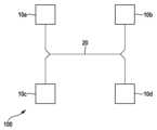
도 1에는, 본원 레이더 센서 시스템(100)의 개략도가 도시되어 있다. 레이더 센서 시스템(100)은 MMIC로서 형성된 4개의 고주파 부품(10a...10d)을 포함한다. 이 경우, 4개라는 개수는 다만 예시일 뿐이며, 본원 레이더 센서 시스템(100)은 4개보다 적거나 많은 고주파 부품도 포함할 수 있다. 또한, 모든 고주파 부품(10a...10d)이 연결되어 있고, 모든 고주파 부품(10a...10d)의 작동 주파수를 동기화하기 위해 이용되는 동기화 네트워크(20)도 확인할 수 있으며, 동기화 과정에서 하나의 고주파 부품(10a...10d)은 동기화 마스터 부품으로서 작용하고, 다른 고주파 부품들은 슬레이브 고주파 부품들로서 작용한다. 동기화 네트워크(20)의 라인들의 기하학적 길이들은 레이더 센서 시스템(100)의 레이더 분해능에 비해 짧은 것이 바람직하며, 그럼으로써 동기화 네트워크(20) 내부에서의 신호 전파 시간이 레이더 분해능(radar resolution)에 매칭된다.1, a schematic diagram of the present
또한, 레이더 센서 시스템(100)은 고주파 부품들(10a...10d)의 안테나 컨트롤러들을 포함한다. 간소화를 위해, 예컨대 안테나, 증폭기, 발진기 등과 같이 레이더 파를 송신하고 수신하기 위해 필요한, 고주파 부품들(10a...10d)의 추가 컴포넌트들은 도면들에 도시되어 있지 않다.Additionally, the
동기화 마스터 부품은 레이더 센서 시스템(100)의 작동 시간 동안 항시 같은 부품이 아니며, 레이더 센서 시스템(100)의 작동 시간에 걸쳐 적어도 하나의 정의된 기준에 따라 모든 고주파 부품(10a...10d)에 의해 동기화 마스터 부품의 기능이 수행된다.The synchronization master component is not the same component at all times during the operating time of the
통상, 레이더 센서 시스템 내에서는, 고주파수 생성을 수행하는 하나의 부품에 마스터의 역할이 할당되고, 다른 고주파 부품들은 상기 부품으로부터 고주파 동기화 신호를 공급받는다. 고주파 동기화 신호는, 레이더 센서 시스템(100)의 높은 각도 분해능을 가능하게 하기 위해 고주파 부품들(10a...10d)의 높은 코히어런스를 제공하는 데 필요하다. 이를 위해, 종래 기술에서는, 특수 설계된 모듈들(specialized module)이 고주파수의 발생 및 추가 신호 처리를 위해 사용된다.Typically, within a radar sensor system, the role of master is assigned to one component that performs high-frequency generation, and other high-frequency components receive high-frequency synchronization signals from the component. The high frequency synchronization signal is needed to provide high coherence of the
그러나 고주파 모듈 개발을 위한 비용이 점점 높아지는 경우, 예컨대 더 작은 노드 크기(node size)를 위한 마스킹 비용이 더 높은 경우, 비록 실질적인 실리콘 표면이 상대적으로 더 크더라도, 동일한 유형의 복수의 모듈을 이용하는 것이 비용 측면에서 유리한 것으로 보인다. 이런 방식으로, 본 발명에 의해, 비용 효과적이고 중복적인 레이더 센서 시스템을 실현하는 바람직한 가능성이 달성된다.However, as costs for high-frequency module development become increasingly higher, for example, masking costs for smaller node sizes are higher, it is advisable to use multiple modules of the same type, even if the actual silicon surface is relatively larger. It appears to be advantageous in terms of cost. In this way, by means of the invention the advantageous possibility of realizing a cost-effective and redundant radar sensor system is achieved.
본 발명에 의해, 하나의 고주파 부품으로부터 역할 교대(rolling) 방식으로 다른 모든 고주파 부품으로 마스터의 역할이 이임된다. 이는 바람직하게, 예컨대 열 관리 영역에서 레이더 센서 시스템(100)을 위한 유리한 작동 특성들을 도출한다.By the present invention, the role of master is transferred from one high-frequency component to all other high-frequency components in a rolling manner. This advantageously leads to advantageous operating characteristics for the
도 2에는, 도 1의 레이더 센서 시스템(100)의 배치가 더 자세한 상세도로 도시되어 있으며, 여기서는 고주파 부품들(10a...10d)이 동기화 네트워크(20)의 전기 라인들의 더 짧은 길이를 가능하게 하기 위해 상호 간에 정의된 각도로 배치됨으로써, 레이더 센서 시스템(100)의 검출 정확도가 최적화될 수 있다는 것을 확인할 수 있다.In FIG. 2 the arrangement of the
마스터 모듈은 레이더 센서 시스템(100)의 정상 작동 모드 중에 후술되는 기능 중 다수를 담당한다.The master module is responsible for many of the functions described below during normal operating modes of the
- PLL을 이용한 주파수 생성(예: 77GHz) 및 경우에 따른 클록 발생(예: 50MHz),- Frequency generation using PLL (e.g. 77 GHz) and in some cases clock generation (e.g. 50 MHz),
- 고주파 동기화 신호의 출력 및 증폭,- Output and amplification of high-frequency synchronization signals,
- 부분적으로 송신 신호의 공급,- supply of partially transmitted signals,
- 기저대역으로 혼합,- Blended into baseband,
- 경우에 따라 AD 변환 및 디지털 신호의 출력.- In some cases, AD conversion and output of digital signals.
첫 번째와 두 번째에 언급한 기능은 일반적으로 마스터 고주파 부품만 담당하고, 그 외 나머지 3가지 기능은 레이더 센서 시스템(100)의 모든 관여 고주파 부품(10a...10d)이 담당한다.The first and second functions are generally handled only by the master high-frequency component, and the remaining three functions are handled by all involved high-frequency components (10a...10d) of the
마스터 부품의 손실 전력 증가는, 상한 온도[고온(HT)]의 범위 내에서, 마스터 부품(10a...10d)이 슬레이브 모듈들(10a...10d)보다 더 이른 시점에 스위치 오프될 수밖에 없게 하고(또는 성능이 저하되게 하고), 그렇게 하여 가용성이 저하된다.The increase in power loss of the master component inevitably causes the master component (10a...10d) to be switched off earlier than the slave modules (10a...10d) within the upper temperature limit [high temperature (HT)]. (or degrade performance), thereby reducing availability.
그에 추가로, 상기 부품은, HT 한계 온도 근처에서 상대적으로 더 오래 작동하기 때문에, 유효 수명에 걸쳐 더 강하게 열화된다. 그러므로 본 발명에 의해, (예컨대 온도 센서를 이용하여) 개별 고주파 부품들의 온도를 검출하고, 최저 온도를 갖는 고주파 부품(10a...10d)에 동기화 마스터 역할을 할당하는 점이 제안된다.Additionally, because the components operate relatively longer near their HT limit temperatures, they deteriorate more strongly over their useful life. Therefore, according to the present invention, it is proposed to detect the temperature of individual high-frequency components (e.g. using a temperature sensor) and assign the synchronization master role to the high-
요컨대 항상 하나의 동일한 고주파 부품(10a...10d)이 마스터 역할을 점유하고, 그에 따라 슬레이브 부품들보다 더 고온이라면, 슬레이브 부품들에 비해 상승한 그 온도는 기저대역에서 위상의 잠재적 편차들을 야기한다. 이렇게 해서 예컨대 마스터 부품은 기저대역에서 슬레이브 부품들에 비해 30°만큼 오프셋된 위상을 갖는데, 이러한 편차는 각도 추정에서 오류를 야기하기 때문에 최대한 발생하지 않아야 한다. 이는 레이더 센서 시스템(100)의 작동 동안, 제안된 마스터 부품(10a...10d)의 역할 교대에 의해 바람직하게 지원된다.In short, if one and the same high-frequency component (10a...10d) always occupies the master role and is therefore hotter than the slave components, its elevated temperature relative to the slave components causes potential phase deviations in the baseband. . In this way, for example, the master component has a phase offset of 30° relative to the slave components at baseband. This deviation causes errors in angle estimation and should be avoided as much as possible. This is advantageously supported by the proposed alternation of roles of the
위상 외에 진폭도 온도에 걸쳐 드리프트를 보이며, 그런 까닭에 고주파 부품들(10a...10d) 간의 온도차가 방지되어야 한다.In addition to phase, amplitude also exhibits drift over temperature, and therefore temperature differences between the high-frequency components (10a...10d) must be prevented.
역할 교대식 마스터 기능을 위해, 다수의 정의된 선택 기준이 사용될 수 있다.For a rotating master function, a number of defined selection criteria can be used.
- 확률적인 랜덤 원리에 따른 마스터 기능의 교체,- Replacement of the master function according to the stochastic random principle,
- 예컨대 마스터 고주파 부품에 의해 50MHz 클록도 발생하고 림프 홈 기능이 제공되는 경우, 레이더 센서 시스템(100)의 "선호 측(preferred side)"에서 마스터 기능을 담당,- For example, if a 50 MHz clock is also generated by the master high-frequency component and a limp home function is provided, the “preferred side” of the
- 예컨대 고주파 부품들(10a...10d)의 기하학적 배치의 시계 방향으로 또는 시계 반대 방향으로 기설정 패턴에 따른 마스터 기능의 교체.- Replacement of the master function according to a preset pattern, e.g. clockwise or counterclockwise of the geometrical arrangement of the high-
레이더 센서 시스템(100)의 마스터 고주파 부품으로서 고주파 부품(10a...10d)을 역할 교대 방식으로 작동하기 위한, 앞서 별도로 설명하지 않은 또 다른 기준들도 가능하다.Other criteria not separately described above are also possible for operating the high-
바람직하게, 제안된 방법은 레이더 센서 시스템에서뿐만 아니라, 복수의 고주파 부품을 포함하는 모든 제품에서 사용될 수 있다. 바람직하게, 본원 레이더 센서 시스템은 자동차 분야에서 사용된다.Advantageously, the proposed method can be used not only in radar sensor systems, but also in any product containing a plurality of high-frequency components. Preferably, the radar sensor system herein is used in the automotive field.
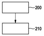
도 3에는, 레이더 센서 시스템을 작동하기 위한 방법의 기본 흐름도가 도시되어 있다.3, a basic flow diagram of a method for operating a radar sensor system is shown.
단계 200에서, 각각 하나 이상의 안테나를 이용하는 정의된 개수의 고주파 부품(10a...10d)을 이용하여 레이더 파를 송신 및 수신하는 단계가 수행된다.In
단계 210에서, 정의된 개수의 고주파 부품(10a...10d)과 연결되어 있는 동기화 네트워크(20)를 이용하여 고주파 부품들(10a...10d)의 작동 주파수를 동기화하는 단계가 수행되며, 동기화 마스터의 기능은 적어도 하나의 정의된 기준에 따라 모든 고주파 부품(10a...10d)이 담당한다.In
바람직하게는, 제안된 방법은 레이더 센서 시스템(100)의 (도시되지 않은) 제어 장치에서 실행되는 소프트웨어로서 구현될 수 있다. 바람직하게는, 이러한 방식으로 방법의 간단한 가변성이 지원된다.Preferably, the proposed method can be implemented as software running on a control device (not shown) of the
따라서, 통상의 기술자는, 본 발명의 핵심에서 벗어나지 않으면서, 상기에 기술되지 않았거나 부분적으로만 기술된 실시예들도 실현할 수 있다.Accordingly, a person skilled in the art can realize embodiments not described above or only partially described without departing from the core of the present invention.
Claims (8)
Translated fromKorean모든 고주파 부품(10a...10d)과 연결되어 모든 고주파 부품(10a...10d)의 작동 주파수가 동기화될 수 있게 하는 동기화 네트워크(20);
를 포함하는 레이더 센서 시스템(100)으로서,
모든 고주파 부품(10a...10d)으로부터 정의된 적어도 하나의 기준에 따라서 동기화 마스터가 제공될 수 있고,
상기 동기화 마스터는 온도 기준에 따라 고주파 부품들(10a...10d) 중에서 선택될 수 있는, 레이더 센서 시스템(100).A defined number of high-frequency components 10a...10d, each comprising one or more antennas for transmitting and/or receiving radar waves and one or more antenna controllers for operating the one or more antennas ( 10a...10d); and
A synchronization network (20) connected to all high-frequency components (10a...10d) so that the operating frequencies of all high-frequency components (10a...10d) can be synchronized;
A radar sensor system 100 including,
A synchronization master can be provided according to at least one defined criterion from all high-frequency components 10a...10d,
Radar sensor system (100), wherein the synchronization master can be selected among high-frequency components (10a...10d) according to temperature criteria.
- 각각 하나 이상의 안테나를 이용하는 정의된 개수의 고주파 부품(10a...10d)을 이용하여 레이더 파들을 송신 및 수신하는 단계와;
- 정의된 개수의 고주파 부품(10a...10d)과 연결되어 있는 동기화 네트워크(20)를 이용하여 고주파 부품들(10a...10d)의 작동 주파수를 동기화하는 단계;를 포함하며, 이 경우,
- 모든 고주파 부품(10a...10d)으로부터 정의된 적어도 하나의 기준에 따라서 동기화 마스터가 제공될 수 있고,
상기 동기화 마스터는 온도 기준에 따라 고주파 부품들(10a...10d) 중에서 선택될 수 있는, 레이더 센서 시스템의 작동 방법.
As a method for operating the radar sensor system 100, the method includes:
- transmitting and receiving radar waves using a defined number of high-frequency components (10a...10d), each using one or more antennas;
- synchronizing the operating frequencies of the high-frequency components (10a...10d) using a synchronization network (20) connected to a defined number of high-frequency components (10a...10d), where ,
- a synchronization master can be provided according to at least one defined criterion from all high-frequency components 10a...10d,
Method of operation of a radar sensor system, wherein the synchronization master can be selected among high-frequency components (10a...10d) according to temperature criteria.
Applications Claiming Priority (3)
| Application Number | Priority Date | Filing Date | Title |
|---|---|---|---|
| DE102018203117.7 | 2018-03-01 | ||
| DE102018203117.7ADE102018203117A1 (en) | 2018-03-01 | 2018-03-01 | Radar sensor system and method for operating a radar sensor system |
| PCT/EP2019/050728WO2019166146A1 (en) | 2018-03-01 | 2019-01-12 | Radar sensor system and method for operating a radar sensor system |
Publications (2)
| Publication Number | Publication Date |
|---|---|
| KR20200128090A KR20200128090A (en) | 2020-11-11 |
| KR102659834B1true KR102659834B1 (en) | 2024-04-24 |
Family
ID=65019531
Family Applications (1)
| Application Number | Title | Priority Date | Filing Date |
|---|---|---|---|
| KR1020207027911AActiveKR102659834B1 (en) | 2018-03-01 | 2019-01-12 | Radar sensor system, and method of operation of the radar sensor system |
Country Status (9)
| Country | Link |
|---|---|
| US (1) | US11579245B2 (en) |
| EP (1) | EP3759511B1 (en) |
| JP (1) | JP6963115B2 (en) |
| KR (1) | KR102659834B1 (en) |
| CN (1) | CN111801589B (en) |
| CA (1) | CA3092374A1 (en) |
| DE (1) | DE102018203117A1 (en) |
| MX (1) | MX2020008921A (en) |
| WO (1) | WO2019166146A1 (en) |
Families Citing this family (2)
| Publication number | Priority date | Publication date | Assignee | Title |
|---|---|---|---|---|
| DE102018203934A1 (en) | 2018-03-15 | 2019-09-19 | Robert Bosch Gmbh | Radar sensor system and method for operating a radar sensor system |
| DE102019216517B3 (en)* | 2019-10-25 | 2021-03-18 | Daimler Ag | Method for synchronizing at least two sensor systems |
Citations (3)
| Publication number | Priority date | Publication date | Assignee | Title |
|---|---|---|---|---|
| US20110122026A1 (en) | 2009-11-24 | 2011-05-26 | Delaquil Matthew P | Scalable and/or reconfigurable beamformer systems |
| US20150153445A1 (en)* | 2013-12-03 | 2015-06-04 | Nxp B.V. | Multichip automotive radar system, a radar chip for such a system, and a method of operating such a system |
| US20170147018A1 (en) | 2015-11-19 | 2017-05-25 | Honeywell International Inc. | Automatic master-slave system and approach |
Family Cites Families (20)
| Publication number | Priority date | Publication date | Assignee | Title |
|---|---|---|---|---|
| BE544068A (en)* | 1954-12-31 | |||
| DE19931928A1 (en)* | 1999-07-08 | 2001-01-11 | Bosch Gmbh Robert | Radar transmitter |
| JP2002299943A (en)* | 2001-04-02 | 2002-10-11 | Murata Mfg Co Ltd | Phased array antenna device and radar device using the same |
| JP4087802B2 (en)* | 2004-02-10 | 2008-05-21 | 三菱電機株式会社 | Millimeter-wave transceiver module and abnormality monitoring method |
| GB0614093D0 (en)* | 2006-07-14 | 2006-08-23 | Bae Systems Plc | Deployable antenna system |
| JP4983409B2 (en)* | 2007-06-04 | 2012-07-25 | 富士通株式会社 | Phase-locked oscillator and multi-radar system using the same |
| DE102008044355A1 (en)* | 2008-12-04 | 2010-06-10 | Robert Bosch Gmbh | Modular radar system |
| US8274426B2 (en)* | 2009-04-30 | 2012-09-25 | Greina Technologies, Inc | High-resolution, active reflector radio frequency ranging system |
| CN102313885B (en)* | 2010-06-30 | 2013-06-26 | 中国科学院电子学研究所 | Multi-dimensional microwave imaging system and method |
| DE102010040696A1 (en)* | 2010-09-14 | 2012-03-15 | Robert Bosch Gmbh | Radar sensor for motor vehicles, in particular RCA sensor |
| US8847823B2 (en)* | 2012-01-09 | 2014-09-30 | Lockheed Martin Corporation | Dimensionally tolerant multiband conformal antenna arrays |
| DE102012201990B4 (en) | 2012-02-10 | 2023-02-16 | Robert Bosch Gmbh | Radar sensor with monitoring circuit |
| US9116244B1 (en)* | 2013-02-28 | 2015-08-25 | Rockwell Collins, Inc. | System for and method of weather phenomenon detection using multiple beams |
| DE102013213483A1 (en)* | 2013-07-10 | 2015-01-15 | Conti Temic Microelectronic Gmbh | Use of a signal generating unit integrated in a microcontroller for controlling at least one voltage-controlled oscillator of high-frequency components of a radar sensor |
| US9473071B2 (en)* | 2013-07-15 | 2016-10-18 | Infineon Technologies Ag | System and method for a radio frequency system |
| LU92331B1 (en)* | 2013-12-10 | 2015-06-11 | Iee Sarl | Radar sensor with frequency dependent beam steering |
| DE102014222837A1 (en)* | 2014-11-10 | 2016-05-12 | Robert Bosch Gmbh | radar system |
| CN105607053B (en)* | 2015-09-09 | 2018-05-04 | 湖北中南鹏力海洋探测系统工程有限公司 | A kind of float type high-frequency ground wave radar system |
| DE102015218542A1 (en) | 2015-09-28 | 2017-03-30 | Robert Bosch Gmbh | Integrated high-frequency circuit, radar sensor and operating method |
| CN106953157B (en)* | 2017-04-17 | 2023-06-27 | 上海瀚界科技发展有限公司 | An antenna device for a radar sensor |
- 2018
- 2018-03-01DEDE102018203117.7Apatent/DE102018203117A1/enactivePending
- 2019
- 2019-01-12CACA3092374Apatent/CA3092374A1/enactivePending
- 2019-01-12WOPCT/EP2019/050728patent/WO2019166146A1/ennot_activeCeased
- 2019-01-12KRKR1020207027911Apatent/KR102659834B1/enactiveActive
- 2019-01-12EPEP19700498.9Apatent/EP3759511B1/enactiveActive
- 2019-01-12JPJP2020545465Apatent/JP6963115B2/enactiveActive
- 2019-01-12USUS16/958,143patent/US11579245B2/enactiveActive
- 2019-01-12CNCN201980016531.0Apatent/CN111801589B/enactiveActive
- 2019-01-12MXMX2020008921Apatent/MX2020008921A/enunknown
Patent Citations (3)
| Publication number | Priority date | Publication date | Assignee | Title |
|---|---|---|---|---|
| US20110122026A1 (en) | 2009-11-24 | 2011-05-26 | Delaquil Matthew P | Scalable and/or reconfigurable beamformer systems |
| US20150153445A1 (en)* | 2013-12-03 | 2015-06-04 | Nxp B.V. | Multichip automotive radar system, a radar chip for such a system, and a method of operating such a system |
| US20170147018A1 (en) | 2015-11-19 | 2017-05-25 | Honeywell International Inc. | Automatic master-slave system and approach |
Also Published As
| Publication number | Publication date |
|---|---|
| CN111801589B (en) | 2024-08-27 |
| CN111801589A (en) | 2020-10-20 |
| KR20200128090A (en) | 2020-11-11 |
| JP2021515221A (en) | 2021-06-17 |
| EP3759511A1 (en) | 2021-01-06 |
| CA3092374A1 (en) | 2019-09-06 |
| DE102018203117A1 (en) | 2019-09-05 |
| US20200355787A1 (en) | 2020-11-12 |
| US11579245B2 (en) | 2023-02-14 |
| MX2020008921A (en) | 2020-10-01 |
| JP6963115B2 (en) | 2021-11-05 |
| WO2019166146A1 (en) | 2019-09-06 |
| EP3759511B1 (en) | 2024-08-21 |
Similar Documents
| Publication | Publication Date | Title |
|---|---|---|
| CN104678366B (en) | Multichip automotive radar system, a radar chip for such a system, and a method of operating such a system | |
| KR102659834B1 (en) | Radar sensor system, and method of operation of the radar sensor system | |
| CN105765402B (en) | Radar device and control method thereof | |
| CN111103530A (en) | Duty cycle monitor circuit and method for duty cycle monitoring | |
| KR102685365B1 (en) | Radar sensor system, and method of operation of the radar sensor system | |
| JP7138176B2 (en) | Radar sensor device and method of providing frequency | |
| US20240077578A1 (en) | Cascaded radar system with improved availability | |
| CN111566509B (en) | Radar system with clock generator integrated in central control unit | |
| US20210003674A1 (en) | Control device, irradiation system, control method, and program | |
| JP6982195B2 (en) | How to operate the radar sensor system and radar sensor system | |
| KR102711667B1 (en) | Radar sensor system, and method of operating the radar sensor system | |
| JP5977308B2 (en) | Electronic circuit having sleep mode | |
| KR100646892B1 (en) | Synchronous circuit | |
| JPS6376639A (en) | Clock synchronization method | |
| GB2352941A (en) | Synchronisation arrangement | |
| JPH0514263A (en) | Phase synchronization monitoring method |
Legal Events
| Date | Code | Title | Description |
|---|---|---|---|
| PA0105 | International application | St.27 status event code:A-0-1-A10-A15-nap-PA0105 | |
| PG1501 | Laying open of application | St.27 status event code:A-1-1-Q10-Q12-nap-PG1501 | |
| PA0201 | Request for examination | St.27 status event code:A-1-2-D10-D11-exm-PA0201 | |
| E902 | Notification of reason for refusal | ||
| PE0902 | Notice of grounds for rejection | St.27 status event code:A-1-2-D10-D21-exm-PE0902 | |
| E13-X000 | Pre-grant limitation requested | St.27 status event code:A-2-3-E10-E13-lim-X000 | |
| P11-X000 | Amendment of application requested | St.27 status event code:A-2-2-P10-P11-nap-X000 | |
| P13-X000 | Application amended | St.27 status event code:A-2-2-P10-P13-nap-X000 | |
| E701 | Decision to grant or registration of patent right | ||
| PE0701 | Decision of registration | St.27 status event code:A-1-2-D10-D22-exm-PE0701 | |
| PR0701 | Registration of establishment | St.27 status event code:A-2-4-F10-F11-exm-PR0701 | |
| PR1002 | Payment of registration fee | St.27 status event code:A-2-2-U10-U12-oth-PR1002 Fee payment year number:1 | |
| PG1601 | Publication of registration | St.27 status event code:A-4-4-Q10-Q13-nap-PG1601 |