KR102657960B1 - Force transmitting frame and motion assist apparatus comprising thereof - Google Patents
Force transmitting frame and motion assist apparatus comprising thereofDownload PDFInfo
- Publication number
- KR102657960B1 KR102657960B1KR1020160135106AKR20160135106AKR102657960B1KR 102657960 B1KR102657960 B1KR 102657960B1KR 1020160135106 AKR1020160135106 AKR 1020160135106AKR 20160135106 AKR20160135106 AKR 20160135106AKR 102657960 B1KR102657960 B1KR 102657960B1
- Authority
- KR
- South Korea
- Prior art keywords
- longitudinal member
- transmission frame
- force transmission
- base
- force
- Prior art date
- Legal status (The legal status is an assumption and is not a legal conclusion. Google has not performed a legal analysis and makes no representation as to the accuracy of the status listed.)
- Active
Links
Images


Classifications
- A—HUMAN NECESSITIES
- A63—SPORTS; GAMES; AMUSEMENTS
- A63B—APPARATUS FOR PHYSICAL TRAINING, GYMNASTICS, SWIMMING, CLIMBING, OR FENCING; BALL GAMES; TRAINING EQUIPMENT
- A63B23/00—Exercising apparatus specially adapted for particular parts of the body
- A63B23/035—Exercising apparatus specially adapted for particular parts of the body for limbs, i.e. upper or lower limbs, e.g. simultaneously
- A63B23/04—Exercising apparatus specially adapted for particular parts of the body for limbs, i.e. upper or lower limbs, e.g. simultaneously for lower limbs
- B—PERFORMING OPERATIONS; TRANSPORTING
- B25—HAND TOOLS; PORTABLE POWER-DRIVEN TOOLS; MANIPULATORS
- B25J—MANIPULATORS; CHAMBERS PROVIDED WITH MANIPULATION DEVICES
- B25J9/00—Programme-controlled manipulators
- B25J9/0006—Exoskeletons, i.e. resembling a human figure
- A—HUMAN NECESSITIES
- A61—MEDICAL OR VETERINARY SCIENCE; HYGIENE
- A61F—FILTERS IMPLANTABLE INTO BLOOD VESSELS; PROSTHESES; DEVICES PROVIDING PATENCY TO, OR PREVENTING COLLAPSING OF, TUBULAR STRUCTURES OF THE BODY, e.g. STENTS; ORTHOPAEDIC, NURSING OR CONTRACEPTIVE DEVICES; FOMENTATION; TREATMENT OR PROTECTION OF EYES OR EARS; BANDAGES, DRESSINGS OR ABSORBENT PADS; FIRST-AID KITS
- A61F5/00—Orthopaedic methods or devices for non-surgical treatment of bones or joints; Nursing devices ; Anti-rape devices
- A61F5/01—Orthopaedic devices, e.g. long-term immobilising or pressure directing devices for treating broken or deformed bones such as splints, casts or braces
- A61F5/0102—Orthopaedic devices, e.g. long-term immobilising or pressure directing devices for treating broken or deformed bones such as splints, casts or braces specially adapted for correcting deformities of the limbs or for supporting them; Ortheses, e.g. with articulations
- A61F5/0127—Orthopaedic devices, e.g. long-term immobilising or pressure directing devices for treating broken or deformed bones such as splints, casts or braces specially adapted for correcting deformities of the limbs or for supporting them; Ortheses, e.g. with articulations for the feet
- A—HUMAN NECESSITIES
- A61—MEDICAL OR VETERINARY SCIENCE; HYGIENE
- A61F—FILTERS IMPLANTABLE INTO BLOOD VESSELS; PROSTHESES; DEVICES PROVIDING PATENCY TO, OR PREVENTING COLLAPSING OF, TUBULAR STRUCTURES OF THE BODY, e.g. STENTS; ORTHOPAEDIC, NURSING OR CONTRACEPTIVE DEVICES; FOMENTATION; TREATMENT OR PROTECTION OF EYES OR EARS; BANDAGES, DRESSINGS OR ABSORBENT PADS; FIRST-AID KITS
- A61F2/00—Filters implantable into blood vessels; Prostheses, i.e. artificial substitutes or replacements for parts of the body; Appliances for connecting them with the body; Devices providing patency to, or preventing collapsing of, tubular structures of the body, e.g. stents
- A61F2/50—Prostheses not implantable in the body
- A61F2/60—Artificial legs or feet or parts thereof
- A—HUMAN NECESSITIES
- A61—MEDICAL OR VETERINARY SCIENCE; HYGIENE
- A61F—FILTERS IMPLANTABLE INTO BLOOD VESSELS; PROSTHESES; DEVICES PROVIDING PATENCY TO, OR PREVENTING COLLAPSING OF, TUBULAR STRUCTURES OF THE BODY, e.g. STENTS; ORTHOPAEDIC, NURSING OR CONTRACEPTIVE DEVICES; FOMENTATION; TREATMENT OR PROTECTION OF EYES OR EARS; BANDAGES, DRESSINGS OR ABSORBENT PADS; FIRST-AID KITS
- A61F5/00—Orthopaedic methods or devices for non-surgical treatment of bones or joints; Nursing devices ; Anti-rape devices
- A61F5/01—Orthopaedic devices, e.g. long-term immobilising or pressure directing devices for treating broken or deformed bones such as splints, casts or braces
- A61F5/0102—Orthopaedic devices, e.g. long-term immobilising or pressure directing devices for treating broken or deformed bones such as splints, casts or braces specially adapted for correcting deformities of the limbs or for supporting them; Ortheses, e.g. with articulations
- A61F5/0104—Orthopaedic devices, e.g. long-term immobilising or pressure directing devices for treating broken or deformed bones such as splints, casts or braces specially adapted for correcting deformities of the limbs or for supporting them; Ortheses, e.g. with articulations without articulation
- A61F5/0111—Orthopaedic devices, e.g. long-term immobilising or pressure directing devices for treating broken or deformed bones such as splints, casts or braces specially adapted for correcting deformities of the limbs or for supporting them; Ortheses, e.g. with articulations without articulation for the feet or ankles
- A—HUMAN NECESSITIES
- A61—MEDICAL OR VETERINARY SCIENCE; HYGIENE
- A61H—PHYSICAL THERAPY APPARATUS, e.g. DEVICES FOR LOCATING OR STIMULATING REFLEX POINTS IN THE BODY; ARTIFICIAL RESPIRATION; MASSAGE; BATHING DEVICES FOR SPECIAL THERAPEUTIC OR HYGIENIC PURPOSES OR SPECIFIC PARTS OF THE BODY
- A61H3/00—Appliances for aiding patients or disabled persons to walk about
- A—HUMAN NECESSITIES
- A63—SPORTS; GAMES; AMUSEMENTS
- A63B—APPARATUS FOR PHYSICAL TRAINING, GYMNASTICS, SWIMMING, CLIMBING, OR FENCING; BALL GAMES; TRAINING EQUIPMENT
- A63B21/00—Exercising apparatus for developing or strengthening the muscles or joints of the body by working against a counterforce, with or without measuring devices
- A63B21/40—Interfaces with the user related to strength training; Details thereof
- A63B21/4001—Arrangements for attaching the exercising apparatus to the user's body, e.g. belts, shoes or gloves specially adapted therefor
- A63B21/4011—Arrangements for attaching the exercising apparatus to the user's body, e.g. belts, shoes or gloves specially adapted therefor to the lower limbs
- A—HUMAN NECESSITIES
- A63—SPORTS; GAMES; AMUSEMENTS
- A63B—APPARATUS FOR PHYSICAL TRAINING, GYMNASTICS, SWIMMING, CLIMBING, OR FENCING; BALL GAMES; TRAINING EQUIPMENT
- A63B24/00—Electric or electronic controls for exercising apparatus of preceding groups; Controlling or monitoring of exercises, sportive games, training or athletic performances
- A63B24/0087—Electric or electronic controls for exercising apparatus of groups A63B21/00 - A63B23/00, e.g. controlling load
- B—PERFORMING OPERATIONS; TRANSPORTING
- B25—HAND TOOLS; PORTABLE POWER-DRIVEN TOOLS; MANIPULATORS
- B25J—MANIPULATORS; CHAMBERS PROVIDED WITH MANIPULATION DEVICES
- B25J11/00—Manipulators not otherwise provided for
- A—HUMAN NECESSITIES
- A61—MEDICAL OR VETERINARY SCIENCE; HYGIENE
- A61F—FILTERS IMPLANTABLE INTO BLOOD VESSELS; PROSTHESES; DEVICES PROVIDING PATENCY TO, OR PREVENTING COLLAPSING OF, TUBULAR STRUCTURES OF THE BODY, e.g. STENTS; ORTHOPAEDIC, NURSING OR CONTRACEPTIVE DEVICES; FOMENTATION; TREATMENT OR PROTECTION OF EYES OR EARS; BANDAGES, DRESSINGS OR ABSORBENT PADS; FIRST-AID KITS
- A61F5/00—Orthopaedic methods or devices for non-surgical treatment of bones or joints; Nursing devices ; Anti-rape devices
- A61F5/01—Orthopaedic devices, e.g. long-term immobilising or pressure directing devices for treating broken or deformed bones such as splints, casts or braces
- A61F5/0102—Orthopaedic devices, e.g. long-term immobilising or pressure directing devices for treating broken or deformed bones such as splints, casts or braces specially adapted for correcting deformities of the limbs or for supporting them; Ortheses, e.g. with articulations
- A—HUMAN NECESSITIES
- A61—MEDICAL OR VETERINARY SCIENCE; HYGIENE
- A61H—PHYSICAL THERAPY APPARATUS, e.g. DEVICES FOR LOCATING OR STIMULATING REFLEX POINTS IN THE BODY; ARTIFICIAL RESPIRATION; MASSAGE; BATHING DEVICES FOR SPECIAL THERAPEUTIC OR HYGIENIC PURPOSES OR SPECIFIC PARTS OF THE BODY
- A61H2201/00—Characteristics of apparatus not provided for in the preceding codes
- A61H2201/12—Driving means
- A61H2201/1207—Driving means with electric or magnetic drive
- A—HUMAN NECESSITIES
- A61—MEDICAL OR VETERINARY SCIENCE; HYGIENE
- A61H—PHYSICAL THERAPY APPARATUS, e.g. DEVICES FOR LOCATING OR STIMULATING REFLEX POINTS IN THE BODY; ARTIFICIAL RESPIRATION; MASSAGE; BATHING DEVICES FOR SPECIAL THERAPEUTIC OR HYGIENIC PURPOSES OR SPECIFIC PARTS OF THE BODY
- A61H2201/00—Characteristics of apparatus not provided for in the preceding codes
- A61H2201/14—Special force transmission means, i.e. between the driving means and the interface with the user
- A61H2201/1463—Special speed variation means, i.e. speed reducer
- A—HUMAN NECESSITIES
- A61—MEDICAL OR VETERINARY SCIENCE; HYGIENE
- A61H—PHYSICAL THERAPY APPARATUS, e.g. DEVICES FOR LOCATING OR STIMULATING REFLEX POINTS IN THE BODY; ARTIFICIAL RESPIRATION; MASSAGE; BATHING DEVICES FOR SPECIAL THERAPEUTIC OR HYGIENIC PURPOSES OR SPECIFIC PARTS OF THE BODY
- A61H2201/00—Characteristics of apparatus not provided for in the preceding codes
- A61H2201/16—Physical interface with patient
- A61H2201/1602—Physical interface with patient kind of interface, e.g. head rest, knee support or lumbar support
- A61H2201/164—Feet or leg, e.g. pedal
- A61H2201/1642—Holding means therefor
- A—HUMAN NECESSITIES
- A61—MEDICAL OR VETERINARY SCIENCE; HYGIENE
- A61H—PHYSICAL THERAPY APPARATUS, e.g. DEVICES FOR LOCATING OR STIMULATING REFLEX POINTS IN THE BODY; ARTIFICIAL RESPIRATION; MASSAGE; BATHING DEVICES FOR SPECIAL THERAPEUTIC OR HYGIENIC PURPOSES OR SPECIFIC PARTS OF THE BODY
- A61H2201/00—Characteristics of apparatus not provided for in the preceding codes
- A61H2201/16—Physical interface with patient
- A61H2201/1602—Physical interface with patient kind of interface, e.g. head rest, knee support or lumbar support
- A61H2201/165—Wearable interfaces
Landscapes
- Health & Medical Sciences (AREA)
- Engineering & Computer Science (AREA)
- General Health & Medical Sciences (AREA)
- Orthopedic Medicine & Surgery (AREA)
- Life Sciences & Earth Sciences (AREA)
- Animal Behavior & Ethology (AREA)
- Public Health (AREA)
- Veterinary Medicine (AREA)
- Vascular Medicine (AREA)
- Heart & Thoracic Surgery (AREA)
- Biomedical Technology (AREA)
- Transplantation (AREA)
- Nursing (AREA)
- Physical Education & Sports Medicine (AREA)
- Robotics (AREA)
- Mechanical Engineering (AREA)
- Oral & Maxillofacial Surgery (AREA)
- Cardiology (AREA)
- Biophysics (AREA)
- Rehabilitation Tools (AREA)
- Manipulator (AREA)
- Epidemiology (AREA)
- Pain & Pain Management (AREA)
- Rehabilitation Therapy (AREA)
Abstract
Translated fromKoreanDescription
Translated fromKorean아래의 설명은 힘 전달 프레임 및 이를 포함하는 운동 보조 장치에 관한 것이다.The description below relates to a force transmission frame and an exercise assistance device including the same.
관절이 불편한 노인이나 환자들이 보행을 원활하게 할 수 있는 운동 보조 장치 및 군사용 등의 목적으로 사용자의 근력을 보조하기 위한 장치들이 개발되고 있다.Exercise assistance devices that allow elderly people or patients with joint discomfort to walk more smoothly and devices that assist the user's muscle strength for military purposes are being developed.
일 실시 예에 따르면 힘 전달 프레임은, 베이스; 상기 베이스에 연결되는 제 1 길이 방향 부재; 상기 베이스에 대하여 슬라이딩 가능한 제 2 길이 방향 부재; 및 상기 제 1 길이 방향 부재의 일단 및 제 2 길이 방향 부재의 일단을 고정하는 제 1 고정부를 포함할 수 있다.According to one embodiment, the force transmission frame includes a base; a first longitudinal member connected to the base; a second longitudinal member slidable relative to the base; And it may include a first fixing part that fixes one end of the first longitudinal member and one end of the second longitudinal member.
상기 제 1 길이 방향 부재의 중간 영역 및 제 2 길이 방향 부재의 중간 영역은, 상대적으로 이동 가능할 수 있다.The middle region of the first longitudinal member and the middle region of the second longitudinal member may be relatively movable.
상기 제 1 길이 방향 부재 및 제 2 길이 방향 부재 각각의 중간 영역은, 길이 방향에 수직한 방향으로 작용하는 힘에 대하여 유연할 수 있다.The middle region of each of the first and second longitudinal members may be flexible against a force acting in a direction perpendicular to the longitudinal direction.
상기 제 1 길이 방향 부재 및 제 2 길이 방향 부재 사이의 간격은, 상기 제 1 고정부로부터 상기 베이스로 갈수록 증가할 수 있다.The gap between the first longitudinal member and the second longitudinal member may increase from the first fixing part to the base.
상기 제 1 길이 방향 부재로부터 상기 제 2 길이 방향 부재까지의 간격은, 아래의 수학식에 따라 결정될 수 있다.The distance from the first longitudinal member to the second longitudinal member may be determined according to the equation below.
<수학식><Equation>
(여기서, h(x)는 상기 제 1 길이 방향 부재 및 상기 제 2 길이 방향 부재 사이의 거리, F는 상기 힘 전달 프레임의 일 단부에 작용하는 힘의 크기, T는 상기 제 1 길이 방향 부재에 걸리는 장력의 크기, L은 상기 힘 전달 프레임의 길이, x는 상기 힘 전달 프레임의 베이스로부터 상기 제 1 길이 방향 부재의 임의의 점까지의 거리, p(x)는 x에서의 상기 제 1 길이 방향 부재의 높이)(Where, h(x) is the distance between the first longitudinal member and the second longitudinal member, F is the magnitude of the force acting on one end of the force transmission frame, and T is the distance between the first longitudinal member and the second longitudinal member. The magnitude of the applied tension, L is the length of the force transmission frame, x is the distance from the base of the force transmission frame to an arbitrary point of the first longitudinal member, and p(x) is the first longitudinal direction in x height of member)
상기 힘 전달 프레임은, 상기 제 1 길이 방향 부재 및 상기 제 2 길이 방향 부재 사이에 배치되며, 상기 제 2 길이 방향 부재가 상기 제 1 길이 방향 부재에 대하여 일정한 간격을 유지하게 하는 적어도 하나 이상의 간격 유지 부재를 더 포함할 수 있다.The force transmission frame is disposed between the first longitudinal member and the second longitudinal member, and maintains at least one gap such that the second longitudinal member maintains a constant distance with respect to the first longitudinal member. Additional absences may be included.
상기 적어도 하나 이상의 간격 유지 부재의 높이는, 상기 제 1 고정부로부터 멀어질수록 높아질 수 있다.The height of the at least one space maintaining member may increase as the distance from the first fixing part increases.
상기 힘 전달 프레임은, 상기 베이스에 연결되는 제 3 길이 방향 부재; 상기 베이스에 대하여 슬라이딩 가능한 제 4 길이 방향 부재; 상기 제 3 길이 방향 부재의 일단 및 상기 제 4 길이 방향 부재의 일단을 고정하는 제 2 고정부; 및 상기 제 1 고정부 및 제 2 고정부를 연결하는 고정 부재를 더 포함할 수 있다.The force transmission frame includes a third longitudinal member connected to the base; a fourth longitudinal member slidable relative to the base; a second fixing part for fixing one end of the third longitudinal member and one end of the fourth longitudinal member; And it may further include a fixing member connecting the first fixing part and the second fixing part.
상기 제 2 길이 방향 부재는, 상기 제 1 길이 방향 부재를 기준으로 상기 제 3 길이 방향 부재의 반대편에 배치되고, 상기 제 4 길이 방향 부재는, 상기 제 3 길이 방향 부재를 기준으로 상기 제 1 길이 방향 부재의 반대편에 배치될 수 있다.The second longitudinal member is disposed on an opposite side of the third longitudinal member with respect to the first longitudinal member, and the fourth longitudinal member is disposed on an opposite side of the third longitudinal member with respect to the third longitudinal member. It may be placed on the opposite side of the direction member.
상기 베이스는, 사용자의 뒤발(rearfoot)의 적어도 일부를 지지하고, 상기 제 1 길이 방향 부재는, 사용자의 중간발(midfoot)의 적어도 일부를 지지하고, 상기 제 2 길이 방향 부재는, 상기 사용자가 지면에 직립한 상태에서 상기 제 1 길이 방향 부재 및 지면 사이에 위치하고, 상기 고정부는, 상기 사용자의 앞발(forefoot)의 적어도 일부를 지지할 수 있다.The base supports at least a portion of the user's rearfoot, the first longitudinal member supports at least a portion of the user's midfoot, and the second longitudinal member supports the user's midfoot. Located between the first longitudinal member and the ground in a state of standing upright on the ground, the fixing portion may support at least a portion of the user's forefoot.
일 실시 예에 따르면 운동 보조 장치는, 사용자의 제 1 부분을 지지하기 위한 지지프레임; 상기 제 1 부분에 연결된 사용자의 관절의 운동을 보조 하기 위한 조인트 어셈블리; 및 상기 조인트 어셈블리에 연결되는 베이스와, 상기 베이스에 연결되는 제 1 길이 방향 부재와, 상기 베이스에 대하여 슬라이딩 가능한 제 2 길이 방향 부재와, 상기 제 1 길이 방향 부재의 일단 및 상기 제 2 길이 방향 부재의 일단을 고정하는 고정부를 포함하고, 상기 사용자의 제 2 부분으로 힘을 전달하기 위한 힘 전달 프레임을 포함할 수 있다.According to one embodiment, an exercise assistance device includes: a support frame for supporting a first part of a user; a joint assembly for assisting movement of the user's joints connected to the first part; and a base connected to the joint assembly, a first longitudinal member connected to the base, a second longitudinal member slidable with respect to the base, one end of the first longitudinal member, and the second longitudinal member. It may include a fixing part for fixing one end of the user, and a force transmission frame for transmitting force to the second part of the user.
상기 힘 전달 프레임은, 상기 제 1 길이 방향 부재 및 제 2 길이 방향 부재 사이에 배치되며, 상기 제 2 길이 방향 부재가 상기 제 1 길이 방향 부재에 대하여 일정한 간격을 유지하게 하는 적어도 하나 이상의 간격 유지 부재를 더 포함할 수 있다.The force transmission frame is disposed between the first longitudinal member and the second longitudinal member, and at least one space maintaining member that maintains a constant distance between the second longitudinal member and the first longitudinal member. It may further include.
상기 운동 보조 장치는, 상기 제 2 길이 방향 부재로 동력을 전달하기 위한 액추에이터(actuator); 및 상기 액추에이터 및 상기 힘 전달 프레임을 연결하는 동력 전달 케이블을 더 포함할 수 있다.The exercise assistance device includes: an actuator for transmitting power to the second longitudinal member; And it may further include a power transmission cable connecting the actuator and the force transmission frame.
상기 액추에이터는, 상기 조인트 어셈블리에 연결되는 탄성체 지지부; 및 상기 탄성체 지지부에 지지되고, 제 2 길이 방향 부재로 탄성력을 제공하는 탄성체를 포함할 수 있다.The actuator includes an elastic support portion connected to the joint assembly; And it may include an elastic body supported by the elastic body support part and providing elastic force to the second longitudinal member.
상기 액추에이터는, 상기 탄성체 지지부에 대하여 슬라이딩 가능한 슬라이더; 및 상기 슬라이더 및 제 2 길이 방향 부재를 서로 연결하는 동력 전달 케이블을 더 포함하고, 상기 탄성체는 상기 탄성체 지지부 및 슬라이더 사이에 배치될 수 있다.The actuator includes a slider capable of sliding with respect to the elastic support portion; and a power transmission cable connecting the slider and the second longitudinal member to each other, wherein the elastic body may be disposed between the elastic body support portion and the slider.
상기 액추에이터는, 구동원; 및 상기 구동원에 연결되고, 상기 동력 전달 케이블을 감거나 풀기 위한 회전체를 포함할 수 있다.The actuator includes a drive source; And it is connected to the drive source and may include a rotating body for winding or unwinding the power transmission cable.
상기 운동 보조 장치는, 상기 액추에이터 및 제 2 길이 방향 부재 사이에 연결되고, 상기 액추에이터로부터 상기 제 2 길이 방향 부재로 전달되는 힘을 증가시키기 위한 감속기를 더 포함할 수 있다.The exercise assistance device may further include a reducer connected between the actuator and the second longitudinal member to increase the force transmitted from the actuator to the second longitudinal member.
상기 운동 보조 장치는, 상기 액추에이터에서 생성된 동력을 상기 감속기로 전달하기 위한 동력 전달 케이블을 더 포함하고, 상기 감속기는 상기 제 2 길이 방향 부재에 회전 가능하게 설치되는 제 1 움직도르래를 포함하고, 상기 동력 전달 케이블의 제 1 단부는 상기 베이스에 고정되고, 제 2 단부는 액추에이터에 고정되고, 중간 부분은 상기 제 1 움직도르래에 감길 수 있다.The exercise assistance device further includes a power transmission cable for transmitting power generated by the actuator to the reducer, and the reducer includes a first movable pulley rotatably installed on the second longitudinal member, The first end of the power transmission cable is fixed to the base, the second end is fixed to the actuator, and the middle part can be wound around the first movable pulley.
상기 힘 전달 프레임은, 상기 제 2 길이 방향 부재에 나란히 배치되는 제 3 길이 방향 부재를 더 포함하고, 상기 제 1 길이 방향 부재는, 상기 제 2 길이 방향 부재 및 상기 제 3 길이 방향 부재에 각각 일단이 고정되는 제 1 분지부 및 제 2 분지부를 포함할 수 있다.The force transmission frame further includes a third longitudinal member disposed in parallel with the second longitudinal member, wherein the first longitudinal member has one end at each of the second longitudinal member and the third longitudinal member. It may include a fixed first branch and a second branch.
상기 운동 보조 장치는, 상기 제 2 길이 방향 부재 및 상기 제 3 길이 방향 부재로 동력을 전달하기 위한 액추에이터(actuator); 및 상기 액추에이터로부터 전달받은 힘을 상기 제 2 길이 방향 부재 및 상기 제 3 길이 방향 부재로 각각 증가시켜 전달할 수 있는 감속기를 더 포함할 수 있다.The exercise assistance device includes: an actuator for transmitting power to the second longitudinal member and the third longitudinal member; And it may further include a reducer capable of increasing and transmitting the force transmitted from the actuator to the second longitudinal member and the third longitudinal member, respectively.
상기 감속기는, 상기 베이스에 설치되는 고정 도르래; 상기 제 2 길이 방향 부재에 설치되는 제 1 움직도르래; 상기 제 3 길이 방향 부재에 설치되는 제 2 움직도르래; 일단은 상기 액추에이터에 연결되고, 중간 상기 제 1 움직도르래, 고정도르래 및 제 2 움직도르래에 순차적으로 감기고, 타단은 상기 베이스에 고정되는 제 1 동력 전달부; 및 일단은 상기 액추에이터에 연결되고, 중간 부분은 상기 제 2 움직도르래, 고정도르래 및 제 1 움직도르래에 순차적으로 감기고, 타단은 상기 베이스에 고정되는 제 2 동력 전달부를 포함할 수 있다.The reducer includes a fixed pulley installed on the base; a first movable pulley installed on the second longitudinal member; a second movable pulley installed on the third longitudinal member; A first power transmission unit, one end of which is connected to the actuator and sequentially wound around the first movable pulley, the fixed pulley, and the second movable pulley, and the other end of which is fixed to the base; and a second power transmission unit, one end of which is connected to the actuator, the middle portion sequentially wound around the second movable pulley, the fixed pulley, and the first movable pulley, and the other end fixed to the base.
도 1은일 실시 예에 따른 힘 전달 프레임의 측면도이다.
도 2는 일 실시 예에 따른 제 1 길이 방향 부재 및 제 2 길이 방향 부재의 간격을 결정하는 방법을 나타내는 그래프이다.
도 3a 내지 도 3c는 일 실시 예에 따른 힘 전달 프레임에 하중이 가해질 때 힘 전달 프레임이 변형되는 모습을 나타내는 도면이다.
도 4a는 일 실시 예에 따른 힘 전달 프레임을 나타내는 도면이다.
도 4b는 일 실시 예에 따른 힘 전달 프레임의 단면도이다.
도 5는 일 실시 예에 따른 힘 전달 프레임의 측면도를 나타내는 도면이다.
도 6은 일 실시 예에 따른 운동 보조 장치가, 사용자의 토-오프(toe-off)를 보조하는 것을 개념적으로 도시한 것이다.
도 7은 일 실시 예에 따른 운동 보조 장치의 사시도이다.
도 8은 일 실시 예에 따른 운동 보조 장치의 측면도이다.
도 9는 일 실시 예에 따른 힘 전달 프레임의 사시도이다.
도 10은 일 실시 예에 따른 액추에이터를 나타내는 도면이다.
도 11은 일 실시 예에 따른 운동 보조 장치의 사시도이다.
도 12a 및 도 12b는 일 실시 예에 따른 감속기를 나타내는 도면이다.
도 13은 일 실시 예에 따른 힘 전달 프레임의 분해 사시도이다.
도 14는 일 실시 예에 따른 동력 전달 부재 및 동력 전달부를 나타내는 도면이다
도 15은 일 실시 예에 따른 감속기를 나타내는 도면이다.
도 16은 일 실시 예에 따른 힘 전달 프레임의 측면도를 나타내는 도면이다.
도 17은 일 실시 예에 따른 로봇 암을 나타내는 도면이다.1 is a side view of a force transmission frame according to one embodiment.
Figure 2 is a graph illustrating a method for determining the spacing between a first longitudinal member and a second longitudinal member according to one embodiment.
3A to 3C are diagrams illustrating deformation of a force transmission frame when a load is applied to the force transmission frame according to an embodiment.
Figure 4a is a diagram showing a force transmission frame according to one embodiment.
Figure 4b is a cross-sectional view of a force transmission frame according to one embodiment.
Figure 5 is a diagram showing a side view of a force transmission frame according to one embodiment.
FIG. 6 conceptually illustrates how an exercise assistance device assists a user's toe-off, according to an embodiment.
Figure 7 is a perspective view of an exercise assistance device according to an embodiment.
Figure 8 is a side view of an exercise assistance device according to an embodiment.
Figure 9 is a perspective view of a force transmission frame according to one embodiment.
Figure 10 is a diagram showing an actuator according to one embodiment.
Figure 11 is a perspective view of an exercise assistance device according to an embodiment.
12A and 12B are diagrams showing a reducer according to an embodiment.
Figure 13 is an exploded perspective view of a force transmission frame according to one embodiment.
14 is a diagram showing a power transmission member and a power transmission unit according to an embodiment.
Figure 15 is a diagram showing a reducer according to an embodiment.
Figure 16 is a side view of a force transmission frame according to one embodiment.
Figure 17 is a diagram showing a robot arm according to one embodiment.
이하, 실시 예들을 예시적인 도면을 통해 상세하게 설명한다. 각 도면의 구성요소들에 참조부호를 부가함에 있어서, 동일한 구성요소들에 대해서는 비록 다른 도면상에 표시되더라도 가능한 한 동일한 부호를 가지도록 하고 있음에 유의해야 한다. 또한, 실시 예를 설명함에 있어, 관련된 공지 구성 또는 기능에 대한 구체적인 설명이 실시 예에 대한 이해를 방해한다고 판단되는 경우에는 그 상세한 설명은 생략한다.Hereinafter, embodiments will be described in detail through illustrative drawings. When adding reference numerals to components in each drawing, it should be noted that identical components are given the same reference numerals as much as possible even if they are shown in different drawings. Additionally, when describing an embodiment, if a detailed description of a related known configuration or function is judged to impede understanding of the embodiment, the detailed description will be omitted.
또한, 실시 예의 구성 요소를 설명하는 데 있어서, 제 1, 제 2, A, B, (a), (b) 등의 용어를 사용할 수 있다. 이러한 용어는 그 구성 요소를 다른 구성 요소와 구별하기 위한 것일 뿐, 그 용어에 의해 해당 구성 요소의 본질이나 차례 또는 순서 등이 한정되지 않는다. 어떤 구성 요소가 다른 구성요소에 "연결", "결합" 또는 "접속"된다고 기재된 경우, 그 구성 요소는 그 다른 구성요소에 직접적으로 연결되거나 접속될 수 있지만, 각 구성 요소 사이에 또 다른 구성 요소가 "연결", "결합" 또는 "접속"될 수도 있다고 이해되어야 할 것이다.Additionally, in describing the components of the embodiment, terms such as first, second, A, B, (a), and (b) may be used. These terms are only used to distinguish the component from other components, and the essence, order, or order of the component is not limited by the term. When a component is described as being "connected," "coupled," or "connected" to another component, that component may be directly connected or connected to that other component, but there is no need for another component between each component. It should be understood that may be “connected,” “combined,” or “connected.”
어느 하나의 실시 예에 포함된 구성요소와, 공통적인 기능을 포함하는 구성요소는, 다른 실시 예에서 동일한 명칭을 사용하여 설명하기로 한다. 반대되는 기재가 없는 이상, 어느 하나의 실시 예에 기재한 설명은 다른 실시 예에도 적용될 수 있으며, 중복되는 범위에서 구체적인 설명은 생략하기로 한다.Components included in one embodiment and components including common functions will be described using the same names in other embodiments. Unless stated to the contrary, the description given in one embodiment may be applied to other embodiments, and detailed description will be omitted to the extent of overlap.
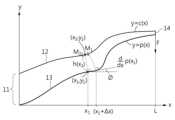
도 1 은 일 실시 예에 따른 힘 전달 프레임의 측면도이고, 도 2는 일 실시 예에 따른 제 1 길이 방향 부재 및 제 2 길이 방향 부재의 간격을 결정하는 예시적인 방법을 나타내는 그래프이다.FIG. 1 is a side view of a force transmission frame according to one embodiment, and FIG. 2 is a graph illustrating an example method of determining a spacing of a first longitudinal member and a second longitudinal member according to an embodiment.
도 1 및 도 2를 참조하면, 일 실시 예에 따른 힘 전달 프레임(1)은, 예를 들어, 사용자(user)의 일부에 힘을 전달할 수 있다. 사용자는 인체, 동물 또는 로봇 등일 수도 있으며, 이에 제한되지 않는다. 예를 들어, 힘 전달 프레임(1)은, 사람의 발바닥을 지지할 수 있다. 다른 예로, 힘 전달 프레임(1)이 로봇의 암(arm)으로 사용될 경우, 로봇의 암에 의해 연결되는 대상체(object)에 힘을 전달할 수 있다. 힘 전달 프레임(1)은, 힘 전달 프레임(1)의 양단에 연결된 구성 사이에 힘을 전달하는 것이면 충분하고, 사용 목적이 제한되는 것은 아님을 밝혀둔다. 힘 전달 프레임(1)은, 베이스(11), 제 1 길이 방향 부재(12), 제 2 길이 방향 부재(13) 및 제 1 고정부(14)를 포함할 수 있다.Referring to FIGS. 1 and 2 , the
제 1 길이 방향 부재(12)의 제 1 단부 및 제 2 길이 방향 부재(13)의 제 1 단부는 서로 고정될 수 있다. 제 1 길이 방향 부재(12)의 제 2 단부는 베이스(11)에 고정되고, 제 2 길이 방향 부재(13)의 제 2 단부는 베이스(11)에 대하여 슬라이딩 할 수 있다. 예를 들어, 베이스(11)는, 제 2 길이 방향 부재(13)가 통과할 수 있는 구멍 또는 홈 등을 포함할 수 있다. 상기 구멍 또는 홈은 제 2 길이 방향 부재(13)가 베이스(11)에 대하여 일정한 방향으로 슬라이딩 하도록 가이드 할 수 있다.The first end of the first
제 2 길이 방향 부재(13)의 중간 영역은, 제 1 길이 방향 부재(12)의 중간 영역에 대하여 상대적으로 이동할 수 있다. 제 2 길이 방향 부재(13) 중 제 1 단부를 제외한 나머지 부분은, 제 1 길이 방향 부재(12)에 고정되지 않을 수 있다. 제 1 길이 방향 부재(12) 및 제 2 길이 방향 부재(13)는, 두께가 얇고 탄성을 갖는 판재, 예를 들어, 플라스틱 또는 스틸 등의 소재로 형성 될 수 있다.The middle region of the second
제 1 고정부(14)는, 제 1 길이 방향 부재(12)의 제 1 단부 및 제 2 길이 방향 부재(13)의 제 1 단부를 고정할 수 있다. 예를 들어, 제 1 고정부(14)는, 볼트 및 너트이거나, 제 1 길이 방향 부재(12)의 재 1 단부 및 제 2 길이 방향 부재(13)의 제 1 단부를 감싸는 끈일 수 있다.The
제 1 길이 방향 부재(12) 및 제 2 길이 방향 부재(13)가, 제 1 고정부(14)로부터 멀어질수록 서로 벌어지는 간격은, 예를 들어, 도 2의 그래프와 같이 결정될 수도 있다. 도 2의 그래프의 원점은, 제 2 길이 방향 부재(13)가 베이스(11)를 통과하는 부분을 의미한다. 예를 들어, 베이스(11)의 제 2 길이 방향 부재(13)가 통과하는 구멍 또는 홈일 수 있다. 제 1 고정부(14)에 작용하는 힘을 F라고 하면, 힘 F는, 사용자가 토-오프(toe-off) 시에 발 끝에 작용하는 힘일 수 있다. 제 1 고정부(14)에 일정한 힘 F가 작용할 때에, 제 1 길이 방향 부재가 좌굴(buckling)되지 않게 하는 h(x)를 결정할 수 있다. 다시 말하면, 간격 h(x)는, 제 1 길이 방향 부재(12)에 걸리는 모멘트 합이 0이 되게 할 수 있다.The distance between the first
제 2 길이 방향 부재(13)의 일 지점 (x1, y1)에서의 법선(normal)과 만나는 제 1 길이 방향 부재(12)의 일 지점을 (x2, y2)라고 할 수 있다. (x2, y2)에 작용하는 모멘트는, 힘 F에 의한 모멘트 M1과, 내측 플레이트에 걸리는 장력 T에 의한 모멘트 M2이다. 한편, 제 1 길이 방향 부재(12)에 걸리는 장력은 (x2, y2)에 모멘트를 작용하지 않으므로 고려할 필요가 없다. 모멘트 M1 및 M2는 아래의 수학식 1 및 수학식 2와 같다.A point of the first
그리고 (x2, y2)에 작용하는 모멘트의 합이 0이 되게 하는 h(x1)는 아래의 수학식 3과 같이 결정될 수 있다. 다시 말하면, 모멘트 M1 및 M2가 동일한 조건을 이용하면 h(x1)는 아래의 수학식 3과 같이 결정될 수 있다.And h(x1 ), which causes the sum of the moments acting on (x2 , y2 ) to be 0, can be determined as in
여기서, Ф는 제 2 길이 방향 부재(13)의 일 지점에 대한 접선이 x축에 대하여 이루는 각도를 의미한다. 한편, 제 2 길이 방향 부재(13)의 높이를 p(x)라고 하면, p(x)는 제 2 길이 방향 부재(13)의 형상을 규정하는 함수라고 할 수 있다. Ф와 p(x)는 아래의 수학식 4의 관계를 갖는다.Here, Ф means the angle formed by the tangent to one point of the second
수학식 4를 이용하여, 수학식 3을 아래의 수학식 5와 같이 표현할 수 있다.Using Equation 4,
제 2 길이 방향 부재(13)의 임의의 점 (x, y)에 대한 식으로 수학식 5를 일반화 시키면 아래의 수학식 6과 같다.If Equation 5 is generalized to an equation for an arbitrary point (x, y) of the second
여기서, T값과 F값의 관계는 제 2 길이 방향 부재(13)의 형상에 대한 함수 p(x)가 주어지면 계산될 수 있다. 그리고 F값의 경우 사용자의 일 부분에 작용되는 힘으로써, 이는 사용자 또는 설계자가 미리 결정할 수 있다. 따라서, 함수 p(x)가 주어지면, 제 2 길이 방향 부재(13)로부터 h(x)의 간격으로 이격되는 제 1 길이 방향 부재(12)의 형상을 결정할 수 있다.Here, the relationship between the T value and the F value can be calculated given the function p(x) for the shape of the second
이와 같은 방법으로 결정된 힘 전달 프레임(1)에 의하면, 제 1 고정부(14)에 힘에 가해져도 힘 전달 프레임(1)이 휘어지지 않고 온전하게 힘을 전달할 수 있다. 힘 전달 프레임(1)이 수학식 6에 따라 결정되면, 이론적으로 힘 전달 프레임(1)이 휘어지지 않고 온전하게 힘을 전달하여야 하지만, 실질적으로 힘 전달 프레임(1)의 부품 사이의 제작 공차 및 조립 공차 등, 다른 여러 가지 요인들에 의한 변형을 고려할 때에, 제 1 고정부(14)에 힘이 가해질 때에 미소 변이가 발생될 수도 있을 것이다. 이와 같은 영향을 고려하더라도, 힘에 대하여 힘 전달 프레임(1)의 양 단부의 강성이 중간 영역의 강성보다 더 크게 될 것임을 알 수 있다.According to the
힘 전달 프레임(1)이 2차원 형상을 가질 경우, 제 1 길이 방향 부재(12)와 제 2 길이 방향 부재(13) 사이의 간격은, 제 1 고정부(14)에 작용하는 힘의 방향에 대하여 수직한 방향으로 거리에 비례하여 결정되는 것으로 이해될 수도 있다. 다시 말해서, 제 1 길이 방향 부재(12) 및 제 2 길이 방향 부재(13) 사이의 간격은, 제 1 고정부(14)로부터 베이스(11)로 갈수록 증가할 수 있다.When the
한편, 이상의 설명은 제 1 길이 방향 부재(12)와 제 2 길이 방향 부재(13) 사이의 간격을 결정하기 위한 하나의 방법에 불과하며, 실시 예들이 반드시 이와 같이 제한되는 것은 아님을 밝혀둔다.Meanwhile, it should be noted that the above description is only a method for determining the gap between the first
도 3a 내지 도 3c는 일 실시 예에 따른 힘 전달 프레임에 하중이 가해질 때 힘 전달 프레임이 변형되는 모습을 나타내는 도면이다.3A to 3C are diagrams illustrating deformation of a force transmission frame when a load is applied to the force transmission frame according to an embodiment.
구체적으로, 도 3a는 힘 전달 프레임(1)의 중간 영역에 힘이 가해진 상태를 도시한 것이고, 도 3b는 힘 전달 프레임(1)의 일 단부에 힘이 가해진 상태를 도시한 것이고, 도 3c는 힘 전달 프레임(1)에 하중이 가해지지 않은 상태를 도시한 것이다.Specifically, Figure 3a shows a state in which force is applied to the middle area of the
제 1 길이 방향 부재(12) 및 제 2 길이 방향 부재(13) 사이의 간격이, 수학식 6에 따라 결정될 경우, 힘 전달 프레임(1)의 양 단부의 강성은, 중간 영역의 강성보다 더 높을 수 있다. 도 3a를 참조하면, 힘 전달 프레임(1)의 중간 영역에 동일한 하중 F가 가해지는 경우에는 힘 전달 프레임(1)의 중간 영역의 위치가 크게 변화될 수 있다. 도 3b를 참조하면, 힘 전달 프레임(1)의 단부에 힘 F가 가해지는 경우에는 힘 전달 프레임(1)의 단부의 위치는 크게 변화되지 않을 수 있다.When the gap between the first
도 4a는 일 실시 예에 따른 힘 전달 프레임을 나타내는 도면이고, 도 4b는 일 실시 예에 따른 힘 전달 프레임의 단면도이다.FIG. 4A is a diagram showing a force transmission frame according to an embodiment, and FIG. 4B is a cross-sectional view of the force transmission frame according to an embodiment.
도 4a 및 도 4b를 참조하면, 일 실시 예에 따른 힘 전달 프레임(2)은, 베이스(21), 제 1 길이 방향 부재(22), 제 2 길이 방향 부재(23), 제 1 고정부(24) 및 적어도 하나 이상의 간격 유지 부재(25)를 포함할 수 있다.Referring to FIGS. 4A and 4B, the force transmission frame 2 according to one embodiment includes a
간격 유지 부재(25)는, 제 1 길이 방향 부재(22) 및 제 2 길이 방향 부재(23) 사이에 배치되어, 제 1 길이 방향 부재(22) 및 제 2 길이 방향 부재(23)의 간격을 유지할 수 있다. 간격 유지 부재(25)는, 예를 들어, 제 2 길이 방향 부재(23)가 통과할 수 있는 구멍 또는 홈을 가질 수 있다. 상기 구멍 또는 홈은 제 2 길이 방향 부재(23)가 간격 유지 부재(25)와 접촉하여, 일정한 방향으로 슬라이딩 하도록 가이드 할 수 있다. 간격 유지 부재(25)는, 예를 들어, 제 1 길이 방향 부재(22) 및 제 2 길이 방향 부재(23) 중 어느 하나에 고정될 수 있다. 간격 유지 부재(25)의 높이는, 예를 들어, 도 1 및 도 2에서 설명한 제 1 길이 방향 부재(12) 및 제 2 길이 방향 부재(13)의 간격으로 결정될 수 있다.The
도 5는 일 실시 예에 따른 힘 전달 프레임의 측면도를 나타내는 도면이다.Figure 5 is a diagram showing a side view of a force transmission frame according to one embodiment.
도 5를 참조하면, 힘 전달 프레임(3)은 베이스(31), 제 1 길이 방향 부재(32), 제 2 길이 방향 부재(33), 제 1 고정부(34) 및 간격 유지 부재(35)를 포함할 수 있다.Referring to Figure 5, the
간격 유지 부재(35)는 상하 방향으로 형성된 복수 개의 홈을 포함 할 수 있다. 다른 예로, 간격 유지 부재(35)는 상하 방향으로 다수 회 절곡된 형상일 수 있다. 예를 들어, 간격 유지 부재(25)는, 사인파(sine wave), 구형파(square wave) 또는 지그재그(zigzag) 형상을 가질 수 있다.The
도 6은 일 실시 예에 따른 운동 보조 장치가, 사용자의 토-오프(toe-off)를 보조하는 것을 개념적으로 도시한 것이다.FIG. 6 conceptually illustrates how an exercise assistance device assists a user's toe-off, according to an embodiment.
도 6을 참조하면, 일 실시 예에 따른 운동 보조 장치(4)는, 사용자에 착용되어 사용자의 운동을 보조할 수 있다. 사용자는 인체, 동물 또는 로봇 등일 수도 있으며, 이에 제한되지 않는다. 운동 보조 장치(4)는, 힘 전달 프레임(43) 및 동력 전달 케이블(45)을 포함할 수 있다. 도 6은 운동 보조 장치(4)가, 사용자의 발의 운동을 보조하는 경우에 대하여 예시적으로 도시하였으나, 운동 보조 장치(4)는, 사용자의 손목, 팔꿈치 및 어깨 등 상체의 다른 부분이나, 무릎, 고관절 등의 하체의 다른 부분을 보조하는 것도 가능하다. 다시 말하면, 운동 보조 장치(4)는, 사용자의 일 부분의 운동을 보조할 수 있다.Referring to FIG. 6, the exercise assistance device 4 according to one embodiment may be worn by the user and assist the user's exercise. The user may be a human body, an animal, or a robot, but is not limited thereto. The exercise assistance device 4 may include a
힘 전달 프레임(43)은, 유연하므로, 말기 입각기(terminal stance) 전후 과정에서 발바닥의 굽힘(bending) 동작에 순응하여 유연하게 휘어질 수 있다. 또한 양 단부는, 중간 영역에 비하여 강성하므로, 힘 전달 프레임(43)에 연결된 동력 전달 케이블(45)을 통하여 전달되는 장력에 의해 힘 전달 프레임(43)의 전단 부분은 지면을 강성하게 밀어냄으로써, 사용자의 토-오프(toe-off) 동작을 보조할 수 있다.Since the
이상의 운동 보조 장치(4)의 구체적인 실시 예에 대하여 후술하기로 한다.Specific examples of the above exercise assistance device 4 will be described later.
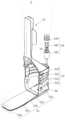
도 7은 일 실시 예에 따른 운동 보조 장치의 사시도이고, 도 8은 일 실시 예에 따른 운동 보조 장치의 측면도이고, 도 9는 일 실시 예에 따른 힘 전달 프레임의 사시도이다.FIG. 7 is a perspective view of an exercise assistance device according to an embodiment, FIG. 8 is a side view of an exercise assistance device according to an embodiment, and FIG. 9 is a perspective view of a force transmission frame according to an embodiment.
도 7 내지 도 9를 참조하면, 일 실시 예에 따른 운동 보조 장치(5)는, 지지프레임(51), 조인트 어셈블리(52), 힘 전달 프레임(53), 액추에이터(54), 동력 전달 케이블(55) 및 감속기(56)를 포함할 수 있다.7 to 9, the exercise assistance device 5 according to an embodiment includes a
지지프레임(51) 및 힘 전달 프레임(53)은, 사용자의 관절을 기준으로 서로 반대편에 배치되어 사용자를 지지할 수 있다. 예를 들어, 운동 보조 장치(5)가 사용자의 발목의 운동을 보조하는 경우, 지지프레임(51) 및 힘 전달 프레임(53)은 사용자의 발목을 중심으로 서로 반대편에 배치될 수 있으며, 지지프레임(51)은 신체의 발목 위 부분, 예를 들어 종아리를 지지할 수 있고, 힘 전달 프레임(53)는 신체의 발목의 아래 부분, 예를 들어 발을 지지할 수 있다.The
지지프레임(51)은, 예를 들어, 사용자의 이탈을 방지하기 위해, 사용자의 일부를 부분적으로 감싸는 구조를 가질 수 있다. 지지프레임(51)은, 예를 들어, 사용자의 종아리 둘레를 전체적으로 지지하기 위한 탈부착식 벨트를 포함할 수 있다. 지지프레임(51)의 하단은, 조인트 어셈블리(52)와 연결될 수 있다.The
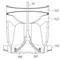
조인트 어셈블리(52)는 사용자의 관절의 운동을 보조할 수 있다. 조인트 어셈블리(52)는, 예를 들어, 사용자가 발목 관절(talocrural joint)을 중심으로 배굴(dorsi-flexion) 또는 척굴(plantar-flexion) 동작하는 것을 보조할 수 있다. 다시 말해서, 조인트 어셈블리(52)는, 지지프레임(51)이 힘 전달 프레임(53)에 대하여 상대적으로 회전 가능하게 할 수 있다. 조인트 어셈블리(52)는, 커버 프레임(521), 미들 프레임(522), 바닥 프레임(523), 및 커버 연결부(524)를 포함할 수 있다.The
일렬로 배열되는 커버 프레임(521), 미들 프레임(522) 및 바닥 프레임(523)은, 예를 들어, 발목을 감싸는 U-형상일 수 있다.The
커버 프레임(521)의 양단의 하면은, 접촉면을 포함하고, 접촉면은 일정한 곡률에 의하여 형성될 수 있다. 접촉면은 반복되는 일정한 크기의 기어 치형을 포함하고, 일정한 곡률은 기어 치형의 베이스 서클(base circle)로 적용될 수 있다.The lower surfaces of both ends of the
미들 프레임(522)의 양단은, 접촉면을 포함하고, 접촉면은 일정한 곡률에 의하여 형성될 수 있다. 접촉면은 반복되는 일정한 크기의 기어 치형을 포함하고, 일정한 곡률은 기어 치형의 베이스 서클(base circle)로 적용될 수 있다. 도 7은 미들 프레임(522)이 복수 개인 경우를 예시적으로 도시하였으나, 미들 프레임(522)은 1개일 수도 있고, 미들 프레임(522) 없이 커버 프레임(521) 및 바닥 프레임(523)이 직접 연결될 수도 있다. 복수 개의 미들 프레임(522) 중 서로 인접한 미들 프레임(522)들은 서로 맞물리는 접촉부를 각각 포함할 수 있다.Both ends of the
바닥 프레임(521)의 양단의 상면은, 접촉면을 포함하고, 접촉면은 일정한 곡률에 의하여 형성될 수 있다. 접촉면은 반복되는 일정한 크기의 기어 치형을 포함하고, 일정한 곡률은 기어 치형의 베이스 서클(base circle)로 적용될 수 있다.The upper surfaces of both ends of the
커버 프레임(521)의 접촉면 및 미들 프레임(522)의 접촉면에 형성되는 기어 치형은, 서로 맞물릴 수 있다. 바닥 프레임(523)의 접촉면 및 미들 프레임(522)의 접촉면에 형성되는 기어 치형은, 서로 맞물릴 수 있다.Gear teeth formed on the contact surface of the
커버 연결부(524)는, 사용자의 발의 길이 방향을 축으로 커버 프레임(521) 및 지지프레임(51)을 상대적으로 회전 가능하도록 연결할 수 있다. 위와 같은 구조에 의하면, 사용자의 내전(inversion) 또는 외전(eversion) 운동에 순응하여 힘 전달 프레임(53)이 회전될 수 있으므로, 사용자의 착용감을 향상시킬 수 있다.The
힘 전달 프레임(53)은, 지지프레임(51)이 지지하고 있는 사용자의 제 1 부분에 적어도 하나 이상의 관절으로 연결된, 사용자의 제 2 부분에 힘을 전달할 수 있다. 예를 들어, 지지프레임(51)이 사용자의 종아리를 지지할 경우, 힘 전달 프레임(53)은, 사용자의 발바닥에 힘을 전달할 수 있다. 힘 전달 프레임(53)은, 사용자의 뒤발(rearfoot)의 적어도 일부를 지지하기 위한 베이스(531)와, 사용자의 중간발(midfoot)의 적어도 일부를 지지하기 위한 제 1 길이 방향 부재(532)와, 제 1 단부가 제 1 길이 방향 부재(533)에 고정되고 제 2 단부는 베이스(531)에 대하여 슬라이딩 가능한 제 2 길이 방향 부재(533)와, 사용자의 앞발(forefoot)의 적어도 일부를 지지하기 위한 고정부(534)와, 제 1 길이 방향 부재(532) 및 제 2 길이 방향 부재(533)의 간격을 유지하기 위한 간격 유지 부재(535)를 포함할 수 있다.The
힘 전달 프레임(5)은 사용자의 앞발부터 뒤발까지 지지할 수 있도록 너비보다는 길이가 더 큰 형태를 가질 수 있다. 힘 전달 프레임(5) 중 사용자의 중간발과 접촉하는 중간 영역은 유연하므로, 사용자의 착용감을 향상시킬 수 있다. 한편, 힘 전달 프레임(5) 중 동력 전달 케이블(55)로부터 힘을 전달받는 제 1 단부와, 사용자의 앞발로 힘을 전달하는 제 2 단부의 강성은, 중간 영역에 비하여 높으므로, 동력 전달 케이블(55)로부터 앞발까지 힘을 충분히 전달할 수 있다.The force transmission frame 5 may have a shape in which the length is greater than the width so as to support the user from the front foot to the back foot. The middle area of the force transmission frame 5 that contacts the user's middle foot is flexible, thereby improving the user's wearing comfort. Meanwhile, the rigidity of the first end that receives force from the
액추에이터(54)는, 제 2 길이 방향 부재(533)에 힘을 제공함으로써, 사용자의 푸쉬-오프(push-off) 동작을 보조할 수 있다. 액추에이터(54)가 제 2 길이 방향 부재(533)를 당기면, 먼저 제 2 길이 방향 부재(533)가 휘어지면서 사용자의 뒤발을 지면으로부터 밀어 올리고(힐-오프, heel-off), 다음으로 제 2 길이 방향 부재(533) 자체에 걸리는 장력에 의해 제 2 길이 방향 부재(533)가 복원되면서 사용자의 토-오프(toe-off) 동작을 보조할 수 있다. 액추에이터(54)는, 예를 들어, 도 7 내지 도 10과 같이 탄성체 등을 이용한 수동 액추에이터일 수도 있고, 도 11과 같이 모터 등을 이용한 능동 액추에이터일 수도 있다. 이하 탄성체를 이용한 수동 액추에이터에 대하여 예시적으로 설명하기로 한다. 예를 들어, 액추에이터(54)는, 탄성체(542)와, 탄성체(542)를 수용하기 위한 수용 공간을 포함하는 탄성체 지지부(541)와, 탄성체(542)를 기준으로 탄성체 지지부(541)의 반대편에 배치되는 슬라이더(543)를 포함할 수 있다.The
탄성체(542)는, 예를 들어, 입각기(stance phase) 중 푸쉬-오프 단계 전까지 탄성체(542)가 압축 또는 인장되었다가, 푸쉬-오프 단계에서 다시 평형상태로 돌아가며 복원력을 생성할 수 있다. 예를 들어, 탄성체(542)의 하단은, 탄성체 지지부(541)에 고정될 수 있다. 예를 들어, 탄성체(542)의 상단은, 슬라이더(543)에 고정될 수 있다. 다시 말해서, 탄성체(542)는 탄성체 지지부(541) 및 슬라이더(543) 사이에 배치될 수 있다. 이와 같은 구조에 의하면, 동력 전달 케이블(55)에 인장력이 인가될 때, 슬라이더(543)가 탄성체 지지부(541) 쪽으로 슬라이딩 됨으로써, 탄성체(542)를 압축시킴으로써 위치 에너지가 증가될 수 있다.For example, the
동력 전달 케이블(55)은, 액추에이터(54) 및 힘 전달 프레임(53)을 연결하고, 상호 간에 동력을 전달시킬 수 있다. 예를 들어, 동력 전달 케이블(55)의 일단은 탄성체 지지부(541)를 관통하여 슬라이더(543)에 연결되고, 동력 전달 케이블(55)의 타단은 제 2 길이 방향 부재(533)에 연결될 수 있다. 동력 전달 케이블(55)은, 예를 들어, 와이어, 케이블, 스트링, 고무줄, 스프링, 벨트, 또는 체인 등의 길이 방향 부재일 수 있다.The
사용자의 푸쉬-오프 전 배굴(dorsi-flexion) 또는 척굴(plantar-flexion)동작 시, 조인트 어셈블리(52)의 프레임들(521, 522, 523)의 중간 영역이 서로 벌어지거나 오므라들면서, 액추에이터(54) 및 힘 전달 프레임(53) 사이의 거리는 변화될 수 있다. 액추에이터(54) 및 힘 전달 프레임(53) 사이의 거리가 변화됨에 따라서, 동력 전달 케이블(55)에 걸리는 장력은 탄성체(542)의 길이를 변화시킬 수 있다. 이와 같은 과정에서, 탄성체(542)의 위치 에너지(potential energy)는 증가될 수 있고, 증가된 위치 에너지는, 사용자의 푸쉬-오프 동작 시, 방출되어 푸쉬-오프 동작을 보조 할 수 있다. 다시 말해서, 방출된 위치에너지는, 동력 전달 케이블(55)을 통해 힘 전달 프레임(53)에 전달되고, 힘 전달 프레임(53)에 전달된 에너지는, 사용자의 뒤발을 당길 수 있다. 또한 힘 전달 프레임(53)에 전달된 에너지는, 사용자의 앞발이 지면을 미는 힘을 제공할 수 있다.When the user performs a dorsi-flexion or plantar-flexion motion before push-off, the middle regions of the
감속기(56)는, 액추에이터(54)로부터 전달받은 동력을 감속시켜 제 2 길이 방향 부재(533)로 전달할 수 있다. 예를 들어, 감속기(56)는, 힘 전달 프레임(53) 및 동력 전달 부재(55) 사이에 연결될 수 있다. 감속기(56)에 대한 설명은 도 12 등을 참조하여 후술하기로 한다.The
도 10은 일 실시 예에 따른 액추에이터를 나타내는 도면이다.Figure 10 is a diagram showing an actuator according to one embodiment.
도 10을 참조하면, 액추에이터(64)는, 탄성체(642)와, 탄성체(642)를 수용하기 위한 수용 공간을 포함하는 탄성체 지지부(641)를 포함할 수 있다.Referring to FIG. 10 , the
예를 들어, 탄성체(642)의 제 1 단부는, 탄성체 지지부(641)의 수용 공간 일측에 고정되고, 제 2 단부는, 동력 전달 케이블(55)과 연결될 수 있다. 이와 같은 구조에 의하면, 동력 전달 케이블(55)에 인장력이 인가될 때, 탄성체(542)가 신장되면서 위치 에너지가 증가될 수 있다.For example, the first end of the
도 11은 일 실시 예에 따른 운동 보조 장치의 사시도이다.Figure 11 is a perspective view of an exercise assistance device according to an embodiment.
도 11을 참조하면, 일 실시 예에 따른 운동 보조 장치(7)는, 지지프레임(51), 조인트 어셈블리(52), 힘 전달 프레임(53), 액추에이터(74) 및 동력 전달 케이블(55)를 포함할 수 있다. 도 11은 능동식 액추에이터(74)를 예시적으로 나타내는 도면이다.Referring to FIG. 11, the
액추에이터(74)는, 구동원(742) 및 회전체(741)를 포함하고, 동력 전달 케이블(55)은 회전체(741) 및 힘 전달 프레임(53) 사이에 연결되어 힘을 전달할 수 있다.The
구동원(742)은, 전압, 전류 및/또는 유압 등을 이용하여 회전체(741)를 회전시키기 위한 동력을 생성할 수 있으며, 구동원(742)의 종류는 제한되지 않음을 밝혀둔다. 구동원(742)은, 예를 들어, 지지 프레임(51)의 일측에 배치될 수 있다. 한편, 구동원(742)은, 지지 프레임(51) 이외의 부분, 예를 들면, 사용자의 상체에 배치되어 회전체(741)에 원격으로 연결될 수 도 있다.It should be noted that the
회전체(741)는, 동력 전달 케이블(55)을 감거나 풀어줌으로써 동력 전달 케이블(55)을 통하여 힘 전달 프레임(53)으로 동력을 전달할 수 있다. 예를 들어, 회전체(741)는, 도 11과 같이 지지프레임(51)의 일측에 배치될 수 있으나, 회전체(741)의 위치가 제한되는 것은 아님을 밝혀둔다.The
도 12a 및 도 12b는 일 실시 예에 따른 감속기를 나타내는 도면이다.12A and 12B are diagrams showing a reducer according to an embodiment.
도 12a 및 도 12b를 참조하면, 일 실시 예에 따른 감속기(56)는, 제 2 길이 방향 부재(533)에 회전 가능하게 설치되는 움직도르래(561)를 포함할 수 있다. 움직도르래(561)는 제 2 길이 방향 부재(533)와 마찬가지로, 베이스(531)에 대하여 슬라이딩 할 수 있다.Referring to FIGS. 12A and 12B, the
동력 전달 케이블(55)의 제 1 단부는 베이스(531)에 고정되고, 제 2 단부는 액추에이터에 고정되고, 중간 부분은 움직도르래(561)에 감길 수 있다. 이와 같은 구조에 의하면, 액추에이터가 동력 전달 케이블(55)에 T만큼의 장력을 인가할 때, 제 2 길이 방향 부재(533)에는 2T의 장력이 인가될 수 있다.The first end of the
도 13은 일 실시 예에 따른 힘 전달 프레임의 분해 사시도이다.Figure 13 is an exploded perspective view of a force transmission frame according to one embodiment.
도 13을 참조하면, 힘 전달 프레임(63)은, 베이스(631), 제 1 길이 방향 부재(632), 제 2 길이 방향 부재(633), 제 3 길이 방향 부재(636), 고정부(634) 및 간격 유지 부재(635)를 포함할 수 있다.Referring to FIG. 13, the
제 1 길이 방향 부재(632)는, 제 2 길이 방향 부재(633)의 제 1 단부 및 제 3 길이 방향 부재(636)의 제 1 단부에 각각 고정되는 제 1 분지부(6321) 및 제 2 분지부(6322)를 포함할 수 있다.The first
제 3 길이 방향 부재(636)는, 제 2 길이 방향 부재(633)와 나란히 배치될 수 있다. 제 3 길이 방향 부재(636)는, 제 2 길이 방향 부재(633)와 마찬가지로 베이스(631)에 대하여 슬라이딩 할 수 있다.The third
이와 같은 구조의 힘 전달 프레임(63)이 사용자의 인솔(insole)로 사용될 경우, 힘 전달 프레임(63)의 좌우가 분리되어, 사용자가 내전(inversion) 또는 외전(eversion) 운동을 할 때 느끼는 착용감을 향상 시킬 수 있다.When the
도 14는 일 실시 예에 따른 동력 전달 케이블 및 동력 전달부를 나타내는 도면이고, 도 15는 일 실시 예에 따른 감속기를 나타내는 도면이다.Figure 14 is a diagram showing a power transmission cable and a power transmission unit according to an embodiment, and Figure 15 is a diagram showing a reducer according to an embodiment.
도 14 및 15를 참조하면, 일 실시 예에 따른 감속기(66)는, 제 2 길이 방향 부재(633)에 회전 가능하게 설치되는 제 1 움직도르래(663)와, 제 3 길이 방향 부재(636)에 회전 가능하게 설치되는 제 2 움직도르래(664)와, 베이스(631)에 설치되는 고정도르래(665)와, 동력 전달 케이블(55)에 연결되는 제 1 동력 전달부(666) 및 제 2 동력 전달부(667)를 포함할 수 있다.Referring to Figures 14 and 15, the
제 1 동력 전달부(666)는, 제 1 움직도르래(663), 고정도르래(665) 및 제 2 움직도르래(664)를 순차적으로 감은 뒤 베이스(631)에 고정될 수 있다. 제 2 동력 전달부(667)는, 제 2 움직도르래(664), 고정도르래(665) 및 제 1 움직도르래(663)를 순차적으로 감은 뒤 베이스(631)에 고정될 수 있다.The first
장력 T는 제 1 동력 전달부(666) 및 제 2 동력 전달부(667)로 각각 T/2로 나뉘어질 수 있다. 이와 같은 구조에 의하면, 액추에이터가 동력 전달 케이블(55)에 T만큼의 장력을 인가할 때, 제 1 동력 전달부(666) 및 제 2 동력 전달부(667)에는 각각 T/2만큼의 장력이 인가될 수 있다. 또한, 도르래 원리에 의해서, 제 1 동력 전달부(666)는 제 1 움직 도르래(663) 및 제 2 움직 도르래(664)에 각각 T만큼의 장력을 전달할 수 있다. 마찬가지로 제 2 동력 전달부(667)는 제 1 움직 도르래(663) 및 제 2 움직 도르래(664)에 각각 T만큼의 장력을 전달할 수 있다. 결과적으로, 제 2 길이 방향 부재(633) 및 제 3 길이 방향 부재(636)에는 2T의 장력이 인가될 수 있다.The tension T can be divided into T/2 by the first
도 16은 일 실시 예에 따른 힘 전달 프레임의 측면도를 나타내는 도면이다.Figure 16 is a side view of a force transmission frame according to one embodiment.
도 16을 참조하면, 힘 전달 프레임(8)은, 베이스(81), 제 1 길이 방향 부재(82a), 제 2 길이 방향 부재(83a), 제 3 길이 방향 부재(82b), 제 4 길이 방향 부재(83b), 제 1 고정부(84a), 제 2 고정부(84b) 및 고정 부재(85)를 포함할 수 있다. 고정 부재(85)는, 제 1 길이 방향 부재(82a)의 제 1 단부 및 제 2 길이 방향 부재(83a)의 제 1 단부를 고정하는 제 1 고정부(84a)와, 제 3 길이 방향 부재(82b)의 제 1 단부 및 제 4 길이 방향 부재(83b)의 제 1 단부를 고정하는 제 2 고정부(84b)를 연결할 수 있다.Referring to FIG. 16, the
제 1 길이 방향 부재(82a)의 제 1 단부 및 제 2 길이 방향 부재(83a)의 제 1 단부는 서로 고정될 수 있다. 제 1 길이 방향 부재(82a)의 제 2 단부는 베이스(81)에 고정되고, 제 2 길이 방향 부재(83a)의 제 2 단부는 베이스(81)에 대하여 슬라이딩 할 수 있다.The first end of the first
제 3 길이 방향 부재(82b)의 제 1 단부 및 제 4 길이 방향 부재(83b)의 제 1 단부는 서로 고정될 수 있다. 제 3 길이 방향 부재(82b)의 제 2 단부는 베이스(81)에 고정되고, 제 4 길이 방향 부재(83b)의 제 2 단부는 베이스(81)에 대하여 슬라이딩 할 수 있다.The first end of the third
예를 들어, 베이스(81)는, 제 2 길이 방향 부재(83a) 및/또는 제 4 길이 방향 부재(83b)가 통과될 수 있는 구멍 또는 홈 등을 포함할 수 있다. 상기 구멍 또는 홈은 제 2 길이 방향 부재(83a) 및/또는 제 4 길이 방향 부재(83b)가 베이스(81)에 대하여 일정한 방향으로 슬라이딩 하도록 가이드 할 수 있다.For example, the
제 1 길이 방향 부재(82a), 제 2 길이 방향 부재(83a), 제 3 길이 방향 부재(82b) 및 제 4 길이 방향 부재(83b)는, 두께가 얇고 탄성을 갖는 판재, 예를 들어, 플라스틱 또는 스틸 등의 소재로 형성 될 수 있다. 이와 같은 구조에 의하면, 힘 전달 프레임(8)은, 앞서 설명한 다른 실시 예들에 따른 힘 전달 프레임들과 마찬가지로, 양 단부의 강성이 중간 영역의 강성보다 더 클 수 있다.The first
한편, 도 17과 같이 제 2 길이 방향 부재(83a)는, 상기 제 1 길이 방향 부재(82a)를 기준으로 상기 제 3 길이 방향 부재(82b)의 반대편에 배치되고, 상기 제 4 길이 방향 부재(83b)는, 상기 제 3 길이 방향 부재(82b)를 기준으로 상기 제 1 길이 방향 부재(82a)의 반대편에 배치되는 힘 전달 프레임. 이와 같이 베이스(81)에 대하여 슬라이딩 가능한 제 2 길이 방향 부재(83a) 및 제 4 길이 방향 부재(83b)를 서로 이격시켜 배치시키면, 2개의 길이 방향 부재(83a, 83b)가 서로 인접하게 배치되는 경우와 비교할 때, 슬라이딩 동작으로 인한 상호 간의 간섭을 최소화할 수 있으며, 힘 전달 프레임(8)이 절곡 가능한 구동 범위를 향상시킬 수 있다.Meanwhile, as shown in FIG. 17, the second
도 17a는 일 실시 예에 따른 로봇 암을 나타내는 도면이다. 도 17b는 일 실시 예에 따른 로봇 암에 측면 방향의 힘이 작용할 때의 모습을 나태는 도면이다. 도 17c는 일 실시 예에 따른 로봇 암이 동작하는 모습을 나타내는 도면이다.Figure 17a is a diagram showing a robot arm according to one embodiment. FIG. 17B is a diagram illustrating a state when a lateral force acts on a robot arm according to an embodiment. Figure 17c is a diagram showing the operation of a robot arm according to one embodiment.
도 17a 내지 도 17c를 참조하면, 일 실시 예에 따른 로봇 암(9)은, 힘 전달 프레임(8) 및 작용부(98)를 포함할 수 있다.Referring to FIGS. 17A to 17C , the
힘 전달 프레임(8)은, 베이스(81), 제 1 길이 방향 부재(82a), 제 2 길이 방향 부재(83a), 제 3 길이 방향 부재(82b), 제 4 길이 방향 부재(83b), 제 1 고정부(84a), 제 2 고정부(84b) 및 고정 부재(85)를 포함할 수 있다. 고정 부재는, 예를 들어, 수술 도구와 같이 대상체(object)에 직접적으로 접촉하는 부분을 포함할 수 있다.The
힘 전달 프레임(8)의 중간 영역은, 유연하기 때문에, 도 17b와 같이, 제 2 길이 방향 부재(83a) 또는 제 4 길이 방향 부재(83b)에 측면 방향의 힘이 가해지더라도, 고정 부재(85)가 베이스(81)에 대하여 이루는 상대적인 각도는 유지될 수 있다. 따라서, 힘 전달 프레임(8)에 측면 방향의 힘이 가해지더라도, 고정 부재(85)에 연결된 작용부(98)의 각도는 유지될 수 있다.Since the middle region of the
한편, 작용부(98)의 각도를 변화시킬 필요가 있는 경우, 도 17c와 같이, 제 2 길이 방향 부재(83a) 및/또는 제 4 길이 방향 부재(83b)를 베이스(81)에 대하여 슬라이딩시킴으로써, 고정 부재(85)의 각도 또는 위치의 변화를 가져올 수 있다.On the other hand, when it is necessary to change the angle of the
이상과 같이 비록 한정된 도면에 의해 실시 예들이 설명되었으나, 해당 기술분야에서 통상의 지식을 가진 자라면 상기의 기재로부터 다양한 수정 및 변형이 가능하다. 예를 들어, 설명된 기술들이 설명된 방법과 다른 순서로 수행되거나, 및/또는 설명된 구조, 장치 등의 구성요소들이 설명된 방법과 다른 형태로 결합 또는 조합되거나, 다른 구성요소 또는 균등물에 의하여 대치되거나 치환되더라도 적절한 결과가 달성될 수 있다. 그러므로, 다른 구현들, 다른 실시 예들 및 청구범위와 균등한 것들도 후술하는 청구범위의 범위에 속한다.As described above, although the embodiments have been described with limited drawings, various modifications and variations can be made by those skilled in the art from the above description. For example, the described techniques may be performed in a different order than the described method, and/or components of the described structure, device, etc. may be combined or combined in a different form than the described method, or may be used with other components or equivalents. Appropriate results can be achieved even if replaced or substituted by . Therefore, other implementations, other embodiments, and equivalents of the claims also fall within the scope of the following claims.
Claims (21)
Translated fromKorean상기 베이스에 연결되는 제 1 길이 방향 부재;
상기 베이스에 대하여 슬라이딩 가능한 제 2 길이 방향 부재; 및
상기 제 1 길이 방향 부재의 일단 및 제 2 길이 방향 부재의 일단을 고정하는 제 1 고정부를 포함하고,
상기 제 1 길이 방향 부재 및 제 2 길이 방향 부재 사이의 간격은, 상기 제 1 고정부로부터 상기 베이스로 갈수록 증가하는 힘 전달 프레임.Base;
a first longitudinal member connected to the base;
a second longitudinal member slidable relative to the base; and
It includes a first fixing part that fixes one end of the first longitudinal member and one end of the second longitudinal member,
A force transmission frame wherein the gap between the first longitudinal member and the second longitudinal member increases from the first fixing part to the base.
상기 제 1 길이 방향 부재의 중간 영역 및 제 2 길이 방향 부재의 중간 영역은 상대적으로 이동 가능한 힘 전달 프레임.According to claim 1,
A force transmission frame wherein the middle region of the first longitudinal member and the middle region of the second longitudinal member are relatively movable.
상기 제 1 길이 방향 부재 및 제 2 길이 방향 부재 각각의 중간 영역은 길이 방향에 수직한 방향으로 작용하는 힘에 대하여 유연한 힘 전달 프레임.According to claim 1,
A force transmission frame in which a middle region of each of the first and second longitudinal members is flexible with respect to a force acting in a direction perpendicular to the longitudinal direction.
상기 제 1 길이 방향 부재로부터 상기 제 2 길이 방향 부재까지의 간격은, 아래의 수학식에 따라 결정되는 힘 전달 프레임.
<수학식>
(여기서, h(x)는 상기 제 1 길이 방향 부재 및 상기 제 2 길이 방향 부재 사이의 거리, F는 상기 힘 전달 프레임의 일 단부에 작용하는 힘의 크기, T는 상기 제 1 길이 방향 부재에 걸리는 장력의 크기, L은 상기 힘 전달 프레임의 길이, x는 상기 힘 전달 프레임의 베이스로부터 상기 제 1 길이 방향 부재의 임의의 점까지의 거리, p(x)는 x에서의 상기 제 1 길이 방향 부재의 높이)According to claim 1,
A force transmission frame where the distance from the first longitudinal member to the second longitudinal member is determined according to the equation below.
<Equation>
(Where, h(x) is the distance between the first longitudinal member and the second longitudinal member, F is the magnitude of the force acting on one end of the force transmission frame, and T is the distance between the first longitudinal member and the second longitudinal member. The magnitude of the applied tension, L is the length of the force transmission frame, x is the distance from the base of the force transmission frame to an arbitrary point of the first longitudinal member, and p(x) is the first longitudinal direction in x height of member)
상기 제 1 길이 방향 부재 및 상기 제 2 길이 방향 부재 사이에 배치되며, 상기 제 2 길이 방향 부재가 상기 제 1 길이 방향 부재에 대하여 일정한 간격을 유지하게 하는 적어도 하나 이상의 간격 유지 부재를 더 포함하는 힘 전달 프레임.According to claim 1,
A force disposed between the first longitudinal member and the second longitudinal member, the force further comprising at least one space maintaining member that maintains a constant distance between the second longitudinal member and the first longitudinal member. forwarding frame.
상기 적어도 하나 이상의 간격 유지 부재의 높이는 상기 제 1 고정부로부터 멀어질수록 높아지는 힘 전달 프레임.According to claim 6,
A force transmission frame in which the height of the at least one space maintaining member increases as the distance from the first fixing part increases.
상기 베이스에 연결되는 제 3 길이 방향 부재;
상기 베이스에 대하여 슬라이딩 가능한 제 4 길이 방향 부재; 및
상기 제 3 길이 방향 부재의 일단 및 상기 제 4 길이 방향 부재의 일단을 고정하는 제 2 고정부; 및
상기 제 1 고정부 및 상기 제 2 고정부를 연결하는 고정 부재를 더 포함하는 힘 전달 프레임.According to claim 1,
a third longitudinal member connected to the base;
a fourth longitudinal member slidable relative to the base; and
a second fixing part for fixing one end of the third longitudinal member and one end of the fourth longitudinal member; and
A force transmission frame further comprising a fixing member connecting the first fixing part and the second fixing part.
상기 제 2 길이 방향 부재는, 상기 제 1 길이 방향 부재를 기준으로 상기 제 3 길이 방향 부재의 반대편에 배치되고,
상기 제 4 길이 방향 부재는, 상기 제 3 길이 방향 부재를 기준으로 상기 제 1 길이 방향 부재의 반대편에 배치되는 힘 전달 프레임.According to claim 8,
The second longitudinal member is disposed on an opposite side of the third longitudinal member with respect to the first longitudinal member,
The fourth longitudinal member is a force transmission frame disposed on an opposite side of the first longitudinal member with respect to the third longitudinal member.
상기 베이스는, 사용자의 뒤발(rearfoot)의 적어도 일부를 지지하고,
상기 제 1 길이 방향 부재는, 사용자의 중간발(midfoot)의 적어도 일부를 지지하고,
상기 제 2 길이 방향 부재는, 상기 사용자가 지면에 직립한 상태에서 상기 제 1 길이 방향 부재 및 지면 사이에 위치하고,
상기 고정부는, 상기 사용자의 앞발(forefoot)의 적어도 일부를 지지하는 힘 전달 프레임.According to claim 1,
The base supports at least a portion of the user's rearfoot,
The first longitudinal member supports at least a portion of the user's midfoot,
The second longitudinal member is positioned between the first longitudinal member and the ground when the user is standing upright on the ground,
The fixing unit is a force transmission frame that supports at least a portion of the user's forefoot.
상기 제 1 부분에 연결된 사용자의 관절의 운동을 보조 하기 위한 조인트 어셈블리; 및
상기 조인트 어셈블리에 연결되는 베이스와, 상기 베이스에 연결되는 제 1 길이 방향 부재와, 상기 베이스에 대하여 슬라이딩 가능한 제 2 길이 방향 부재와, 상기 제 1 길이 방향 부재의 일단 및 상기 제 2 길이 방향 부재의 일단을 고정하는 고정부를 포함하고, 상기 사용자의 제 2 부분으로 힘을 전달하기 위한 힘 전달 프레임을 포함하는 운동 보조 장치.a support frame for supporting a first part of the user;
a joint assembly for assisting movement of the user's joints connected to the first part; and
A base connected to the joint assembly, a first longitudinal member connected to the base, a second longitudinal member slidable with respect to the base, one end of the first longitudinal member, and a second longitudinal member. An exercise assistance device including a fixing part for fixing one end, and a force transmission frame for transmitting force to a second part of the user.
상기 힘 전달 프레임은,
상기 제 1 길이 방향 부재 및 제 2 길이 방향 부재 사이에 배치되며, 상기 제 2 길이 방향 부재가 상기 제 1 길이 방향 부재에 대하여 일정한 간격을 유지하게 하는 적어도 하나 이상의 간격 유지 부재를 더 포함하는 운동 보조 장치.According to claim 11,
The force transmission frame is,
Movement assistance further comprising at least one space maintaining member disposed between the first longitudinal member and the second longitudinal member, the second longitudinal member maintaining a constant distance from the first longitudinal member. Device.
상기 제 2 길이 방향 부재로 동력을 전달하기 위한 액추에이터(actuator); 및
상기 액추에이터 및 상기 힘 전달 프레임을 연결하는 동력 전달 케이블을 더 포함하는 운동 보조 장치.According to claim 11,
an actuator for transmitting power to the second longitudinal member; and
An exercise assistance device further comprising a power transmission cable connecting the actuator and the force transmission frame.
상기 액추에이터는,
상기 조인트 어셈블리에 연결되는 탄성체 지지부; 및
상기 탄성체 지지부에 지지되고, 제 2 길이 방향 부재로 탄성력을 제공하는 탄성체를 포함하는 운동 보조 장치.According to claim 13,
The actuator is,
an elastic support portion connected to the joint assembly; and
An exercise assistance device comprising an elastic body supported by the elastic body supporter and providing elastic force to a second longitudinal member.
상기 액추에이터는,
상기 탄성체 지지부에 대하여 슬라이딩 가능한 슬라이더; 및
상기 슬라이더 및 제 2 길이 방향 부재를 서로 연결하는 동력 전달 케이블을 더 포함하고,
상기 탄성체는 상기 탄성체 지지부 및 슬라이더 사이에 배치되는 운동 보조 장치.According to claim 14,
The actuator is,
a slider capable of sliding relative to the elastic support portion; and
Further comprising a power transmission cable connecting the slider and the second longitudinal member to each other,
The elastic body is an exercise assistance device disposed between the elastic body support portion and the slider.
상기 액추에이터는,
구동원; 및
상기 구동원에 연결되고, 상기 동력 전달 케이블을 감거나 풀기 위한 회전체를 포함하는 운동 보조 장치.According to claim 13,
The actuator is,
drive source; and
An exercise assistance device connected to the drive source and including a rotating body for winding or unwinding the power transmission cable.
상기 운동 보조 장치는,
상기 액추에이터 및 제 2 길이 방향 부재 사이에 연결되고, 상기 액추에이터로부터 상기 제 2 길이 방향 부재로 전달되는 힘을 증가시키기 위한 감속기를 더 포함하는 운동 보조 장치.According to claim 13,
The exercise assistance device is,
The exercise assistance device is connected between the actuator and the second longitudinal member and further includes a reducer for increasing force transmitted from the actuator to the second longitudinal member.
상기 액추에이터에서 생성된 동력을 상기 감속기로 전달하기 위한 동력 전달 케이블을 더 포함하고,
상기 감속기는 상기 제 2 길이 방향 부재에 회전 가능하게 설치되는 제 1 움직도르래를 포함하고,
상기 동력 전달 케이블의 제 1 단부는 상기 베이스에 고정되고, 제 2 단부는 액추에이터에 고정되고, 중간 부분은 상기 제 1 움직도르래에 감기는 운동 보조 장치.According to clause 17,
Further comprising a power transmission cable for transmitting power generated by the actuator to the reducer,
The reducer includes a first movable pulley rotatably installed on the second longitudinal member,
A first end of the power transmission cable is fixed to the base, a second end is fixed to an actuator, and a middle part is wound around the first movable pulley.
상기 힘 전달 프레임은, 상기 제 2 길이 방향 부재에 나란히 배치되는 제 3 길이 방향 부재를 더 포함하고,
상기 제 1 길이 방향 부재는, 상기 제 2 길이 방향 부재 및 상기 제 3 길이 방향 부재에 각각 일단이 고정되는 제 1 분지부 및 제 2 분지부를 포함하는 운동 보조 장치.According to claim 11,
The force transmission frame further includes a third longitudinal member disposed parallel to the second longitudinal member,
The exercise assistance device wherein the first longitudinal member includes a first branch portion and a second branch portion, one end of which is respectively fixed to the second longitudinal member and the third longitudinal member.
상기 제 2 길이 방향 부재 및 상기 제 3 길이 방향 부재로 동력을 전달하기 위한 액추에이터(actuator); 및
상기 액추에이터로부터 전달받은 힘을 상기 제 2 길이 방향 부재 및 상기 제 3 길이 방향 부재로 각각 증가시켜 전달할 수 있는 감속기를 더 포함하는 운동 보조 장치.According to claim 19,
an actuator for transmitting power to the second longitudinal member and the third longitudinal member; and
An exercise assistance device further comprising a reducer capable of increasing and transmitting the force transmitted from the actuator to the second longitudinal member and the third longitudinal member, respectively.
상기 감속기는,
상기 베이스에 설치되는 고정 도르래;
상기 제 2 길이 방향 부재에 설치되는 제 1 움직도르래;
상기 제 3 길이 방향 부재에 설치되는 제 2 움직도르래;
일단은 상기 액추에이터에 연결되고, 중간 상기 제 1 움직도르래, 고정도르래 및 제 2 움직도르래에 순차적으로 감기고, 타단은 상기 베이스에 고정되는 제 1 동력 전달부; 및
일단은 상기 액추에이터에 연결되고, 중간 부분은 상기 제 2 움직도르래, 고정도르래 및 제 1 움직도르래에 순차적으로 감기고, 타단은 상기 베이스에 고정되는 제 2 동력 전달부를 포함하는 운동 보조 장치.According to claim 20,
The reducer is,
A fixed pulley installed on the base;
a first movable pulley installed on the second longitudinal member;
a second movable pulley installed on the third longitudinal member;
A first power transmission unit, one end of which is connected to the actuator and sequentially wound around the first movable pulley, the fixed pulley, and the second movable pulley, and the other end of which is fixed to the base; and
An exercise assistance device comprising a second power transmission unit, one end of which is connected to the actuator, the middle part sequentially wound around the second movable pulley, the fixed pulley, and the first movable pulley, and the other end fixed to the base.
Priority Applications (4)
| Application Number | Priority Date | Filing Date | Title |
|---|---|---|---|
| KR1020160135106AKR102657960B1 (en) | 2016-10-18 | 2016-10-18 | Force transmitting frame and motion assist apparatus comprising thereof |
| US15/607,909US10744022B2 (en) | 2016-10-18 | 2017-05-30 | Force transmitting frame and motion assistance apparatus including the same |
| CN201710501253.0ACN107953311B (en) | 2016-10-18 | 2017-06-27 | Force transmission frame and exercise assisting device comprising same |
| EP17186777.3AEP3315102B1 (en) | 2016-10-18 | 2017-08-18 | Force transmitting frame, a motion assistance apparatus including the force transmitting frame and a robot arm including the force transmitting frame |
Applications Claiming Priority (1)
| Application Number | Priority Date | Filing Date | Title |
|---|---|---|---|
| KR1020160135106AKR102657960B1 (en) | 2016-10-18 | 2016-10-18 | Force transmitting frame and motion assist apparatus comprising thereof |
Publications (2)
| Publication Number | Publication Date |
|---|---|
| KR20180042652A KR20180042652A (en) | 2018-04-26 |
| KR102657960B1true KR102657960B1 (en) | 2024-04-16 |
Family
ID=59699504
Family Applications (1)
| Application Number | Title | Priority Date | Filing Date |
|---|---|---|---|
| KR1020160135106AActiveKR102657960B1 (en) | 2016-10-18 | 2016-10-18 | Force transmitting frame and motion assist apparatus comprising thereof |
Country Status (4)
| Country | Link |
|---|---|
| US (1) | US10744022B2 (en) |
| EP (1) | EP3315102B1 (en) |
| KR (1) | KR102657960B1 (en) |
| CN (1) | CN107953311B (en) |
Families Citing this family (2)
| Publication number | Priority date | Publication date | Assignee | Title |
|---|---|---|---|---|
| EP3173053B1 (en)* | 2015-11-26 | 2025-04-09 | Samsung Electronics Co., Ltd. | Motion assistance apparatus including a frame assembly |
| DE102021112989A1 (en)* | 2021-05-19 | 2022-11-24 | Otto Bock Healthcare Products Gmbh | orthosis |
Citations (2)
| Publication number | Priority date | Publication date | Assignee | Title |
|---|---|---|---|---|
| JP2010110381A (en)* | 2008-11-04 | 2010-05-20 | Toyota Motor Corp | Walking aid device |
| US20100268137A1 (en)* | 2009-04-16 | 2010-10-21 | Richard Bachmann | Orthotic brace |
Family Cites Families (22)
| Publication number | Priority date | Publication date | Assignee | Title |
|---|---|---|---|---|
| JP3500551B2 (en) | 1995-10-12 | 2004-02-23 | 澄子 山本 | Short leg orthosis |
| KR100401458B1 (en) | 1998-12-31 | 2003-12-18 | 산재의료관리원 | Ankle-Adjustable Artificial Foot |
| US6562075B2 (en) | 2001-03-30 | 2003-05-13 | Barry W. Townsend | Prosthetic foot with tunable performance |
| US6443993B1 (en) | 2001-03-23 | 2002-09-03 | Wayne Koniuk | Self-adjusting prosthetic ankle apparatus |
| US20040064195A1 (en) | 2002-07-15 | 2004-04-01 | Hugh Herr | Variable-mechanical-impedance artificial legs |
| US8075633B2 (en) | 2003-09-25 | 2011-12-13 | Massachusetts Institute Of Technology | Active ankle foot orthosis |
| US7811334B2 (en) | 2004-02-12 | 2010-10-12 | Ossur Hf. | System and method for motion-controlled foot unit |
| JP3955304B2 (en) | 2005-05-17 | 2007-08-08 | 本田技研工業株式会社 | Lumbar orthosis |
| GB0701662D0 (en) | 2006-12-14 | 2007-03-07 | Blatchford & Sons Ltd | A lower limb prosthesis |
| US7530185B2 (en) | 2007-06-22 | 2009-05-12 | Deere & Company | Electronic parallel lift and return to carry on a backhoe loader |
| KR101056621B1 (en) | 2009-02-02 | 2011-08-11 | 조경일 | Ankle and detachable knee pads |
| KR101025512B1 (en)* | 2009-06-16 | 2011-04-04 | 경상대학교산학협력단 | Adaptive walk assistance device for increased walking stability |
| US9492302B2 (en) | 2011-08-15 | 2016-11-15 | North Carolina State University | Apparatus and clutch for using controlled storage and release of mechanical energy to aid locomotion |
| EP2809783A2 (en)* | 2012-02-02 | 2014-12-10 | Invenra, Inc. | High throughput screen for biologically active polypeptides |
| JP6172627B2 (en) | 2012-04-13 | 2017-08-02 | 国立大学法人北見工業大学 | Knee joint |
| FR2991224B1 (en)* | 2012-06-04 | 2014-06-27 | Commissariat Energie Atomique | ARM OF EXOSQUELET WITH ACTUATOR |
| US9066559B2 (en)* | 2012-06-27 | 2015-06-30 | Barry A. Butler | Bi-layer orthotic and tri-layer energy return system |
| JP5939941B2 (en)* | 2012-09-07 | 2016-06-22 | 本田技研工業株式会社 | Power transmission device |
| CN103040594B (en)* | 2013-01-24 | 2014-06-25 | 哈尔滨工业大学 | Pseudo passive power assisting device for ankle joint movement |
| JP5927173B2 (en) | 2013-12-27 | 2016-06-01 | 本田技研工業株式会社 | Joint mechanism |
| US10478368B2 (en) | 2014-09-19 | 2019-11-19 | Samsung Electronics Co., Ltd. | Force transmitting frames and motion assistance apparatuses including the same |
| CN105500343B (en)* | 2016-01-15 | 2017-11-10 | 中国矿业大学 | A kind of line is driven wearable mechanical exoskeleton |
- 2016
- 2016-10-18KRKR1020160135106Apatent/KR102657960B1/enactiveActive
- 2017
- 2017-05-30USUS15/607,909patent/US10744022B2/enactiveActive
- 2017-06-27CNCN201710501253.0Apatent/CN107953311B/enactiveActive
- 2017-08-18EPEP17186777.3Apatent/EP3315102B1/enactiveActive
Patent Citations (2)
| Publication number | Priority date | Publication date | Assignee | Title |
|---|---|---|---|---|
| JP2010110381A (en)* | 2008-11-04 | 2010-05-20 | Toyota Motor Corp | Walking aid device |
| US20100268137A1 (en)* | 2009-04-16 | 2010-10-21 | Richard Bachmann | Orthotic brace |
Also Published As
| Publication number | Publication date |
|---|---|
| US10744022B2 (en) | 2020-08-18 |
| CN107953311A (en) | 2018-04-24 |
| EP3315102B1 (en) | 2025-04-02 |
| US20180104083A1 (en) | 2018-04-19 |
| KR20180042652A (en) | 2018-04-26 |
| EP3315102A1 (en) | 2018-05-02 |
| CN107953311B (en) | 2022-08-09 |
Similar Documents
| Publication | Publication Date | Title |
|---|---|---|
| KR102725145B1 (en) | A supporting module and a motion assist apparatus comprising thereof | |
| KR102496582B1 (en) | A driving module and a motion assist apparatus comprising thereof | |
| KR102250260B1 (en) | A connecting module and a motion assist apparatus comprising thereof | |
| Thalman et al. | Design of a soft ankle-foot orthosis exosuit for foot drop assistance | |
| CN111037535B (en) | Walking aids | |
| KR102432862B1 (en) | A joint assembly and a motion assist apparatus comprising thereof | |
| US11590013B1 (en) | Brace system | |
| KR101912920B1 (en) | Ankle module for gait rehabilitation robot | |
| JP2020032159A (en) | Assist device | |
| KR102657960B1 (en) | Force transmitting frame and motion assist apparatus comprising thereof | |
| KR101932755B1 (en) | Elastic leg exoskeleton with adjustable stiffness device | |
| KR102352338B1 (en) | A connecting module and a motion assist apparatus comprising thereof | |
| KR20210134287A (en) | suit type robot structure for humanoid robot | |
| KR102553064B1 (en) | A frame assembly and a motion assist apparatus comprising thereof | |
| JP7068553B2 (en) | A device designed to be positioned close to a joint and a general system with the above device | |
| KR20240124168A (en) | Wearable robot for ankle joint assistance | |
| US20240033157A1 (en) | Low-profile actuators for assistive wearable devices | |
| JP2016059797A (en) | Force transmitting frames and motion assistance apparatuses including the same | |
| US10583025B2 (en) | Wearing module and motion assistance apparatus including the same | |
| US20240398597A1 (en) | Self-aligning joint assistance device | |
| EP4364712A1 (en) | Motion assistance apparatus | |
| US20230000711A1 (en) | Actuators for assistive wearable devices | |
| KR20250068091A (en) | Gait supporting device using cable customized for gait patient | |
| KR20250068092A (en) | Hybrid gait supporting device | |
| KR20250068093A (en) | Active gait supporting device using anterior and posterior motors |
Legal Events
| Date | Code | Title | Description |
|---|---|---|---|
| PA0109 | Patent application | Patent event code:PA01091R01D Comment text:Patent Application Patent event date:20161018 | |
| PG1501 | Laying open of application | ||
| PA0201 | Request for examination | Patent event code:PA02012R01D Patent event date:20211018 Comment text:Request for Examination of Application Patent event code:PA02011R01I Patent event date:20161018 Comment text:Patent Application | |
| E902 | Notification of reason for refusal | ||
| PE0902 | Notice of grounds for rejection | Comment text:Notification of reason for refusal Patent event date:20231107 Patent event code:PE09021S01D | |
| E701 | Decision to grant or registration of patent right | ||
| PE0701 | Decision of registration | Patent event code:PE07011S01D Comment text:Decision to Grant Registration Patent event date:20240112 | |
| GRNT | Written decision to grant | ||
| PR0701 | Registration of establishment | Comment text:Registration of Establishment Patent event date:20240411 Patent event code:PR07011E01D | |
| PR1002 | Payment of registration fee | Payment date:20240412 End annual number:3 Start annual number:1 | |
| PG1601 | Publication of registration |