KR102657294B1 - Directional wireless power and wireless data communication - Google Patents
Directional wireless power and wireless data communicationDownload PDFInfo
- Publication number
- KR102657294B1 KR102657294B1KR1020237005713AKR20237005713AKR102657294B1KR 102657294 B1KR102657294 B1KR 102657294B1KR 1020237005713 AKR1020237005713 AKR 1020237005713AKR 20237005713 AKR20237005713 AKR 20237005713AKR 102657294 B1KR102657294 B1KR 102657294B1
- Authority
- KR
- South Korea
- Prior art keywords
- wprc
- wireless
- power
- wpts
- beacon
- Prior art date
- Legal status (The legal status is an assumption and is not a legal conclusion. Google has not performed a legal analysis and makes no representation as to the accuracy of the status listed.)
- Active
Links
- 238000004891communicationMethods0.000titledescription41
- 230000005540biological transmissionEffects0.000claimsabstractdescription78
- 238000000034methodMethods0.000claimsabstractdescription46
- 238000010586diagramMethods0.000description22
- 239000013598vectorSubstances0.000description20
- 238000012546transferMethods0.000description11
- 230000005855radiationEffects0.000description7
- 230000001427coherent effectEffects0.000description6
- 230000033001locomotionEffects0.000description6
- 238000001514detection methodMethods0.000description5
- 230000007246mechanismEffects0.000description4
- 230000011664signalingEffects0.000description4
- 238000003491arrayMethods0.000description3
- 230000008859changeEffects0.000description3
- 238000005259measurementMethods0.000description3
- 238000012544monitoring processMethods0.000description3
- 230000003321amplificationEffects0.000description2
- 239000003990capacitorSubstances0.000description2
- 238000013461designMethods0.000description2
- 230000007274generation of a signal involved in cell-cell signalingEffects0.000description2
- 230000006855networkingEffects0.000description2
- 238000003199nucleic acid amplification methodMethods0.000description2
- 230000002093peripheral effectEffects0.000description2
- 230000010363phase shiftEffects0.000description2
- 230000008569processEffects0.000description2
- 230000008054signal transmissionEffects0.000description2
- UGFAIRIUMAVXCW-UHFFFAOYSA-NCarbon monoxideChemical compound[O+]#[C-]UGFAIRIUMAVXCW-UHFFFAOYSA-N0.000description1
- 230000008901benefitEffects0.000description1
- 238000004364calculation methodMethods0.000description1
- 229910002091carbon monoxideInorganic materials0.000description1
- 238000004590computer programMethods0.000description1
- 230000006870functionEffects0.000description1
- 238000003306harvestingMethods0.000description1
- 230000001939inductive effectEffects0.000description1
- 238000002955isolationMethods0.000description1
- 238000012986modificationMethods0.000description1
- 230000004048modificationEffects0.000description1
- 230000003287optical effectEffects0.000description1
- 229920001690polydopaminePolymers0.000description1
- 238000012545processingMethods0.000description1
- 230000010076replicationEffects0.000description1
- 239000004065semiconductorSubstances0.000description1
Images


Classifications
- H—ELECTRICITY
- H02—GENERATION; CONVERSION OR DISTRIBUTION OF ELECTRIC POWER
- H02J—CIRCUIT ARRANGEMENTS OR SYSTEMS FOR SUPPLYING OR DISTRIBUTING ELECTRIC POWER; SYSTEMS FOR STORING ELECTRIC ENERGY
- H02J50/00—Circuit arrangements or systems for wireless supply or distribution of electric power
- H02J50/20—Circuit arrangements or systems for wireless supply or distribution of electric power using microwaves or radio frequency waves
- H—ELECTRICITY
- H01—ELECTRIC ELEMENTS
- H01Q—ANTENNAS, i.e. RADIO AERIALS
- H01Q3/00—Arrangements for changing or varying the orientation or the shape of the directional pattern of the waves radiated from an antenna or antenna system
- H01Q3/26—Arrangements for changing or varying the orientation or the shape of the directional pattern of the waves radiated from an antenna or antenna system varying the relative phase or relative amplitude of energisation between two or more active radiating elements; varying the distribution of energy across a radiating aperture
- H01Q3/30—Arrangements for changing or varying the orientation or the shape of the directional pattern of the waves radiated from an antenna or antenna system varying the relative phase or relative amplitude of energisation between two or more active radiating elements; varying the distribution of energy across a radiating aperture varying the relative phase between the radiating elements of an array
- H—ELECTRICITY
- H02—GENERATION; CONVERSION OR DISTRIBUTION OF ELECTRIC POWER
- H02J—CIRCUIT ARRANGEMENTS OR SYSTEMS FOR SUPPLYING OR DISTRIBUTING ELECTRIC POWER; SYSTEMS FOR STORING ELECTRIC ENERGY
- H02J50/00—Circuit arrangements or systems for wireless supply or distribution of electric power
- H02J50/40—Circuit arrangements or systems for wireless supply or distribution of electric power using two or more transmitting or receiving devices
- H—ELECTRICITY
- H02—GENERATION; CONVERSION OR DISTRIBUTION OF ELECTRIC POWER
- H02J—CIRCUIT ARRANGEMENTS OR SYSTEMS FOR SUPPLYING OR DISTRIBUTING ELECTRIC POWER; SYSTEMS FOR STORING ELECTRIC ENERGY
- H02J50/00—Circuit arrangements or systems for wireless supply or distribution of electric power
- H02J50/80—Circuit arrangements or systems for wireless supply or distribution of electric power involving the exchange of data, concerning supply or distribution of electric power, between transmitting devices and receiving devices
- H—ELECTRICITY
- H04—ELECTRIC COMMUNICATION TECHNIQUE
- H04W—WIRELESS COMMUNICATION NETWORKS
- H04W48/00—Access restriction; Network selection; Access point selection
- H04W48/08—Access restriction or access information delivery, e.g. discovery data delivery
- H04W48/12—Access restriction or access information delivery, e.g. discovery data delivery using downlink control channel
Landscapes
- Engineering & Computer Science (AREA)
- Computer Networks & Wireless Communication (AREA)
- Power Engineering (AREA)
- Computer Security & Cryptography (AREA)
- Signal Processing (AREA)
- Mobile Radio Communication Systems (AREA)
- Near-Field Transmission Systems (AREA)
Abstract
Translated fromKorean
Description
Translated fromKorean관련 출원에 대한 교차 참조Cross-reference to related applications
본 출원은 2018년 4월 25일자로 출원된 미국 정식 출원 번호 제15/962,479호의 이익을 주장하는데, 그 내용은 참조에 의해 본원에 통합된다.This application claims the benefit of U.S. Provisional Application No. 15/962,479, filed April 25, 2018, the contents of which are incorporated herein by reference.
발명의 분야field of invention
본원에서 설명되는 실시형태는 동시적 무선 데이터 통신을 사용한 무선 전력 전달 분야에서의 향상이다.Embodiments described herein are improvements in the field of wireless power transfer using simultaneous wireless data communication.
종래의 무선 전력 전달은 단거리에 걸쳐 전자 디바이스의 배터리를 충전한다. 무선 충전은 전자 디바이스가 무선 충전기와 접촉하거나 또는 매우 근접하는 것을 필요로 하는 자기 또는 유도 충전 기반의 솔루션으로 제한되었다.Conventional wireless power transfer charges the battery of an electronic device over short distances. Wireless charging has been limited to solutions based on magnetic or inductive charging, which require the electronic device to be in contact with or in close proximity to the wireless charger.
무선 충전을 지원하는 데 필요한 회로부 및 무선 충전에 필요한 단거리에 추가하여, 종래의 무선 충전 전자기기는 데이터 통신을 위한 별개의 회로부(circuitry)를 또한 필요로 한다. Bluetooth™(블루투스), Wi-Fi™(와이파이), ZigBee™(지그비), 등등과 같은 별개의 데이터 통신을 지원하는 것은, 관련된 통신 채널을 통해 통신하기 위한 추가적인 하드웨어 및 전력을 필요로 한다. 이들 별개의 데이터 통신을 지원하는 것과 관련되는 전력 및 비용은 불리하다. 따라서, 더 먼 거리에 걸쳐 전자 디바이스를 안전하고 효과적으로 충전할 수 있는 무선 전력 회로부를 구현하기 위한 그리고 동일한 무선 전력 회로부를 활용하여 전자 디바이스와 무선 전력 충전기 사이의 양방향 데이터 통신을 또한 지원하기 위한 필요성이 존재한다.In addition to the circuitry needed to support wireless charging and the short distances required for wireless charging, conventional wireless charging electronics also require separate circuitry for data communication. Supporting discrete data communications such as Bluetooth™, Wi-Fi™, ZigBee™, etc. requires additional hardware and power to communicate over the associated communication channels. The power and costs associated with supporting these separate data communications are disadvantageous. Accordingly, there is a need to implement wireless power circuitry that can safely and effectively charge electronic devices over longer distances and to also support two-way data communication between electronic devices and wireless power chargers utilizing the same wireless power circuitry. exist.
통합 송신기 및/또는 수신기를 사용하여 무선 전력 및 무선 데이터를 송신 및 수신할 수 있는 무선 전력 송신 시스템(wireless power transmission system; WPTS) 및 무선 전력 수신기 클라이언트(wireless power receiver client; WPRC), 및 그에 의해 수행되는 방법의 실시형태가 본원에서 개시된다. 예시적인 실시형태에서, WPTS는 안테나의 어레이 및 안테나의 어레이에 동작 가능하게 커플링되는 무선 수신기를 포함할 수도 있다. 무선 수신기는 안테나의 어레이의 적어도 제1 부분을 통해, 제1 WPRC를 수신하도록, 그리고, 안테나의 어레이의 적어도 제2 부분을 통해, 제2 WPRC로부터 제2 무선 비콘을 수신하도록 구성될 수도 있다. WPTS는 또한 무선 수신기에 동작 가능하게 커플링되는 프로세서를 포함할 수도 있다. 프로세서는 제1 무선 비콘에 기초하여 안테나의 어레이의 적어도 제1 부분에 대한 위상 설정의 제1 구성을 결정하도록 구성될 수도 있다. 프로세서는, 제2 무선 비콘에 기초하여 안테나의 어레이의 적어도 제2 부분에 대한 위상 설정의 제2 구성을 결정하도록 추가로 구성될 수도 있다. WPTS는 안테나의 어레이에 동작 가능하게 커플링되는 무선 송신기를 더 포함할 수도 있다. 무선 송신기는, 안테나의 어레이의 적어도 제1 부분을 통해, 위상 설정의 제1 구성을 사용하여 제1 WPRC로 무선 전력을 지향적으로 송신하도록, 동시에, 안테나의 어레이의 적어도 제2 부분을 통해, 위상 설정의 제2 구성을 사용하여 제2 WPRC로 데이터를 지향적으로 송신하도록 구성될 수도 있다.A wireless power transmission system (WPTS) and a wireless power receiver client (WPRC) capable of transmitting and receiving wireless power and wireless data using an integrated transmitter and/or receiver, and thereby Embodiments of methods performed are disclosed herein. In an example embodiment, a WPTS may include an array of antennas and a wireless receiver operably coupled to the array of antennas. The wireless receiver may be configured to receive a first WPRC via at least a first portion of the array of antennas and to receive a second wireless beacon from a second WPRC via at least a second portion of the array of antennas. The WPTS may also include a processor operably coupled to the wireless receiver. The processor may be configured to determine a first configuration of phase settings for at least a first portion of the array of antennas based on the first wireless beacon. The processor may be further configured to determine a second configuration of phase settings for at least a second portion of the array of antennas based on the second wireless beacon. The WPTS may further include a wireless transmitter operably coupled to the array of antennas. The wireless transmitter is configured to directionally transmit wireless power, via at least a first portion of the array of antennas, to the first WPRC using a first configuration of phase settings, while simultaneously, via at least a second portion of the array of antennas, the phase setting. The configuration may be configured to directedly transmit data to a second WPRC using a second configuration of settings.
다른 실시형태에서, 제1 무선 비콘은 제1 동위상 성분(in-phase component) 및 제1 직교 위상 성분(quadrature-phase component)을 포함할 수도 있고, 제2 무선 비콘은 제2 동위상 성분 및 제2 직교 위상 성분을 포함할 수도 있다. 프로세서는, 제1 무선 비콘의 제1 복소 켤레(complex conjugate)를 결정하고 제2 무선 비콘의 제2 복소 켤레를 결정하도록 추가로 구성될 수도 있다. 제1 WPRC로 지향적으로 송신되는 무선 전력은 제1 복소 켤레를 사용하여 제1 WPRC의 위치에서 집중될 수도 있고, 제2 WPRC로 지향적으로 송신되는 데이터는 제2 복소 켤레를 사용하여 제2 WPRC의 위치에서 집중될 수도 있다.In another embodiment, the first wireless beacon may include a first in-phase component and a first quadrature-phase component, and the second wireless beacon may include a second in-phase component and a first quadrature-phase component. It may also include a second quadrature component. The processor may be further configured to determine a first complex conjugate of the first wireless beacon and determine a second complex conjugate of the second wireless beacon. Wireless power transmitted directionally to the first WPRC may be concentrated at a location of the first WPRC using the first complex conjugate, and data transmitted directionally to the second WPRC may be concentrated at the location of the second WPRC using the second complex conjugate. It may be concentrated in location.
다른 실시형태에서, 제1 복소 켤레는 안테나의 어레이의 적어도 제1 부분의 각각의 안테나에 대해 계산될 수도 있고 제2 복소 켤레는 안테나의 어레이의 적어도 제2 부분의 각각의 안테나에 대해 계산될 수도 있다.In another embodiment, a first complex conjugate may be calculated for each antenna of at least a first portion of an array of antennas and a second complex conjugate may be calculated for each antenna of at least a second portion of an array of antennas. there is.
다른 실시형태에서, 제1 WPRC의 위치에서 집중되는 무선 전력의 전력 레벨은 대략 +30 dBm일 수도 있고, 제2 WPRC의 위치에서 집중되는 데이터의 전력 레벨은 대략 -14 dBm일 수도 있다.In another embodiment, the power level of wireless power centered at the location of the first WPRC may be approximately +30 dBm, and the power level of data centered at the location of the second WPRC may be approximately -14 dBm.
다른 실시형태에서, WPTS는 안테나의 어레이의 적어도 제1 부분의 각각의 안테나에 대한 제1 복소 켤레를 계산할 수도 있고 안테나의 어레이의 적어도 제2 부분의 각각의 안테나에 대한 제2 복소 켤레를 계산할 수도 있다.In another embodiment, the WPTS may calculate a first complex conjugate for each antenna of at least a first portion of an array of antennas and calculate a second complex conjugate for each antenna of at least a second portion of an array of antennas. there is.
다른 실시형태에서, WPTS는 합계 송신(sum transmission)에 기초하여 제1 WPRC로의 무선 전력 및 제2 WPRC로의 데이터 둘 모두를 송신할 수도 있다. 합계 송신은 합계 동위상 성분(sum in-phase component) 및 합계 직교 위상 성분(sum quadrature-phase component)을 포함할 수도 있다. 합계 동위상 성분은 제1 복소 켤레의 동위상 성분 및 제2 복소 켤레의 동위상 성분의 축소된 버전(scaled-down version)의 합계일 수도 있다. 합계 직교 위상 성분은 제1 복소 켤레의 직교 위상 성분과 제2 복소 켤레의 직교 위상 성분의 축소된 버전의 합계일 수도 있다.In another embodiment, the WPTS may transmit both wireless power to the first WPRC and data to the second WPRC based on sum transmission. The sum transmission may include a sum in-phase component and a sum quadrature-phase component. The sum in-phase component may be the sum of a scaled-down version of the in-phase component of the first complex conjugate and the in-phase component of the second complex conjugate. The sum quadrature components may be the sum of a reduced version of the quadrature components of the first complex conjugate and the quadrature components of the second complex conjugate.
다른 실시형태에서, 제2 복소 켤레의 동위상 성분의 축소된 버전 및 제2 복소 켤레의 직교 위상 성분의 축소된 버전은 선택된 양만큼, 예를 들면, 대략 34 dB 만큼 축소될 수도 있다.In another embodiment, the scaled-down version of the in-phase component of the second complex conjugate and the scaled-down version of the quadrature component of the second complex conjugate may be scaled by a selected amount, for example, approximately 34 dB.
다른 실시형태에서, 안테나의 어레이의 적어도 제1 부분은 안테나의 어레이의 적어도 제2 부분과 동일할 수도 있다. 안테나의 어레이의 적어도 제1 부분 및 안테나의 어레이의 적어도 제2 부분은 안테나의 어레이의 모든 안테나를 구성할 수도 있다.In another embodiment, at least the first portion of the array of antennas may be the same as at least the second portion of the array of antennas. At least a first portion of the array of antennas and at least a second portion of the array of antennas may constitute all antennas of the array of antennas.
다른 실시형태에서, WPTS는 적어도 제3 WPRC의 각각으로부터 각각의 무선 비콘을 수신할 수도 있다. WPTS는 각각의 무선 비콘에 기초하여 적어도 제3 WPRC의 각각에 대한 안테나의 어레이와 관련되는 위상 설정의 각각의 구성을 결정할 수도 있다. WPTS는, 제1 WPRC로의 무선 전력의 지향성 송신과 동시에, 위상 설정의 각각의 구성을 사용하여 각각의 다른 데이터를 적어도 제3 WPRC의 각각으로 지향적으로 송신할 수도 있다.In another embodiment, the WPTS may receive a respective wireless beacon from each of at least the third WPRC. The WPTS may determine the respective configuration of the phase settings associated with the array of antennas for each of at least the third WPRC based on each wireless beacon. Simultaneously with the directional transmission of wireless power to the first WPRC, the WPTS may also directionally transmit each other data to each of at least the third WPRC using each configuration of phase settings.
다른 실시형태에서, 적어도 제3 WPRC의 각각으로부터의 각기 각각의 무선 비콘은 각각의 동위상 성분 및 각각의 직교 위상 성분을 포함할 수도 있다. WPTS는 적어도 제3 무선 비콘의 각각의 복소 켤레를 결정할 수도 있고, 적어도 제3 WPRC의 각각으로 지향적으로 송신되는 각각의 다른 데이터는 적어도 제3 무선 비콘의 각각의 각각의 복소 켤레를 사용하여 적어도 제3 WPRC의 각각의 각각의 위치에서 WPTS에 의해 집중될 수도 있다.In another embodiment, each wireless beacon from each of at least the third WPRC may include a respective in-phase component and a respective quadrature component. The WPTS may determine the respective complex conjugate of at least the third wireless beacon, and each other data to be directed to each of the at least third WPRCs may determine the respective complex conjugate of at least the third wireless beacon using the respective complex conjugate of each of the at least third wireless beacons. It may be centralized by WPTS at each location of the 3 WPRC.
다른 실시형태에서, WPTS는 안테나의 어레이 및 안테나의 어레이에 커플링되는 무선 수신기를 포함할 수도 있다. 무선 수신기는, 안테나의 어레이의 적어도 제1 부분을 통해, 제1 WPRC로부터 제1 무선 비콘을 수신하도록 구성될 수도 있다. WPTS는 안테나의 어레이에 동작 가능하게 커플링되는 무선 송신기를 더 포함할 수도 있다. WPTS는 제1 무선 비콘에 기초하여 안테나의 어레이의 적어도 제1 부분에 대한 위상 설정의 제1 구성을 결정하도록 구성될 수도 있는 프로세서를 더 포함할 수도 있다. 프로세서는 존재하는 WPRC의 수를 결정하도록 추가로 구성될 수도 있다.In another embodiment, a WPTS may include an array of antennas and a wireless receiver coupled to the array of antennas. A wireless receiver may be configured to receive a first wireless beacon from a first WPRC, via at least a first portion of an array of antennas. The WPTS may further include a wireless transmitter operably coupled to the array of antennas. The WPTS may further include a processor that may be configured to determine a first configuration of phase settings for at least a first portion of the array of antennas based on the first wireless beacon. The processor may be further configured to determine the number of WPRCs present.
하나의 WPRC가 존재한다는 것을 프로세서가 결정하는 제1 조건에서, 무선 송신기는, 안테나의 어레이의 적어도 제1 부분을 통해, 위상 설정의 제1 구성을 사용하여 제1 WPRC로 무선 전력 및 데이터를, 다중화된 양식으로, 지향적으로 송신하도록 추가로 구성될 수도 있다.In a first condition where the processor determines that a WPRC exists, the wireless transmitter transmits wireless power and data, through at least a first portion of the array of antennas, to a first WPRC using a first configuration of phase settings, It may be further configured to transmit directionally in a multiplexed format.
제1 WPRC 및 적어도 제2 WPRC가 존재한다는 것을 프로세서가 결정하는 제2 조건에서, 무선 수신기는, 안테나의 어레이의 적어도 제2 부분을 통해, 제2 WPRC로부터 제2 무선 비콘을 수신하도록 추가로 구성될 수도 있다. 제2 조건에서, 프로세서는, 제2 무선 비콘에 기초하여 안테나의 어레이의 적어도 제2 부분에 대한 위상 설정의 제2 구성을 결정하도록 추가로 구성될 수도 있다. 제2 조건에서, 무선 송신기는 또한, 안테나의 어레이의 적어도 제1 부분을 통해, 위상 설정의 제1 구성을 사용하여 제1 WPRC로 무선 전력을 지향적으로 송신하도록, 동시에, 안테나의 어레이의 적어도 제2 부분을 통해, 위상 설정의 제2 구성을 사용하여 제2 WPRC로 데이터를 지향적으로 송신하도록 추가로 구성될 수도 있다.In a second condition where the processor determines that a first WPRC and at least a second WPRC are present, the wireless receiver is further configured to receive, via at least a second portion of the array of antennas, a second wireless beacon from the second WPRC. It could be. In a second condition, the processor may be further configured to determine a second configuration of phase settings for at least a second portion of the array of antennas based on the second wireless beacon. In a second condition, the wireless transmitter is further configured to transmit wireless power directionally, via at least a first portion of the array of antennas, to the first WPRC using a first configuration of phase settings, while at the same time at least a first portion of the array of antennas. Through part 2, the device may be further configured to directedly transmit data to the second WPRC using a second configuration of phase settings.
다른 실시형태에서, WPTS는, 제1 조건에서, 데이터와는 상이한 주파수 상에서, 상이한 시간 기간 동안, 또는 상이한 주파수 상에서 그리고 상이한 시간 기간 동안 둘 모두에서, 무선 전력을 송신하도록 구성될 수도 있다.In another embodiment, the WPTS may be configured to transmit wireless power on a different frequency, for a different time period, or both on a different frequency and for a different time period than the data in the first condition.
도 1은 예시적인 무선 전력 송신 환경을 포함하는 시스템 다이어그램을 묘사한다.
도 2는 무선 전력 송신 시스템(WPTS)의 예시적인 실시형태의 예시적인 컴포넌트를 예시하는 블록도이다.
도 3은 WPRC의 예시적인 실시형태를 예시하는 블록도이다.
도 4는 무선 신호 전달 환경의 예시적인 실시형태를 예시하는 다이어그램이다.
도 5는 무선 전력 수신기 클라이언트(WPRC)와 WPTS 사이의 신호 교환의 예시적인 실시형태의 신호 다이어그램이다.
도 6은 다수의 WPRC와 WPTS 사이의 신호 교환의 예시적인 실시형태의 신호 다이어그램이다.
도 7은 WPTS에 의해 수행되는 방법의 예시적인 실시형태를 묘사한다.
도 8은 WPTS에 의해 수행되는 방법의 다른 예시적인 실시형태를 묘사한다.
도 9는 WPTS에 의해 수행되는 방법의 다른 예시적인 실시형태를 묘사한다.
도 10은 WPRC에 의해 WPTS로 송신되는 비콘 신호에 대한 예시적인 포맷을 묘사한다.
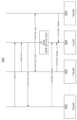
도 11은 WPTS 및 두 개의 WPRC를 포함하는 시스템의 예시적인 실시형태를 묘사하는 다이어그램이다.
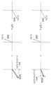
도 12는 도 11의 제1 WPRC에 대응하는 벡터 및 도 11의 제2 WPRC에 대응하는 다른 벡터의 일련의 다이어그램을 묘사한다.
도 13은 WPTS로부터 두 개의 상이한 WPRC로의 집중된 지향성 무선 전력 송신의 예를 묘사하는 다이어그램이다.
도 14는 도 11의 제1 WPRC에 대응하는 벡터 및 도 11의 제2 WPRC에 대응하는 다른 벡터의 다른 일련의 다이어그램을 묘사한다.
도 15는, WPTS로부터 제2 WPRC로의 집중된 지향성 무선 데이터 송신과 동시에, WPTS로부터 제1 WPRC로의 집중된 지향성 무선 전력 송신의 예를 묘사하는 다이어그램이다.1 depicts a system diagram including an example wireless power transmission environment.
2 is a block diagram illustrating example components of an example embodiment of a wireless power transfer system (WPTS).
Figure 3 is a block diagram illustrating an example embodiment of WPRC.
4 is a diagram illustrating an example embodiment of a wireless signaling environment.
5 is a signal diagram of an example embodiment of signal exchange between a wireless power receiver client (WPRC) and WPTS.
6 is a signal diagram of an example embodiment of signal exchange between multiple WPRCs and WPTS.
7 depicts an example embodiment of a method performed by WPTS.
8 depicts another example embodiment of a method performed by WPTS.
9 depicts another example embodiment of a method performed by WPTS.
10 depicts an example format for a beacon signal transmitted by WPRC to WPTS.
11 is a diagram depicting an example embodiment of a system including a WPTS and two WPRCs.
Figure 12 depicts a series of diagrams of a vector corresponding to the first WPRC in Figure 11 and another vector corresponding to the second WPRC in Figure 11.
Figure 13 is a diagram depicting an example of concentrated directional wireless power transmission from WPTS to two different WPRCs.
Figure 14 depicts another series of diagrams of a vector corresponding to the first WPRC in Figure 11 and another vector corresponding to the second WPRC in Figure 11.
FIG. 15 is a diagram depicting an example of focused directional wireless power transmission from a WPTS to a first WPRC simultaneously with focused directional wireless data transmission from the WPTS to a second WPRC.
도 1은 WPTS(101)와 같은 하나 이상의 무선 전력 송신 시스템(WPTS)으로부터의 무선 전력 전달을 예시하는 예시적인 무선 전력 송신 환경(100)을 포함하는 시스템 다이어그램을 묘사한다. 더 구체적으로, 도 1은 하나 이상의 무선 전력 수신기 클라이언트(WPRC)(110a-110c)로의 전력 송신을 예시한다. WPTS(101)는 WPRC(110a-110c)로부터 인코딩된 비콘(111a-111c)을 수신하도록 그리고 무선 전력(112a-112c) 및 무선 데이터(113a-113c)를 WPRC(110a-110c)로 송신하도록 구성될 수도 있다. WPRC(110a-110c)는 WPTS(101)와 같은 하나 이상의 WPTS로부터 무선 전력(112a-112c)을 수신 및 프로세싱하도록 구성될 수도 있다. 예시적인 WPTS(101)의 컴포넌트는 하기에서, 뿐만 아니라 도 2에서 더욱 상세하게 나타내어지고 논의된다. 예시적인 WPRC(110a-110c)의 컴포넌트는 하기에서, 뿐만 아니라 도 3을 참조하여 더욱 상세하게 나타내어지고 논의된다.1 depicts a system diagram including an example wireless
WPTS(101)는 무선 전력(112a-112c)을 WPRC(110a-110c)로 전달할 수 있을 수도 있는 다수의 안테나(103a-103n), 예를 들면 복수의 안테나를 포함하는 안테나 어레이를 포함할 수도 있다. 몇몇 실시형태에서, 안테나는 적응적 위상 맞춤(adaptively-phased) 무선 주파수(radio frequency; RF) 안테나이다. WPTS(101)는 가간섭성(coherent) 전력 송신 신호를 WPRC(110a-110c)로 전달하기 위한 적절한 위상을 결정할 수 있을 수도 있다. 안테나(103a-103n)를 포함하는 안테나 어레이의 각각의 안테나는, 각각의 다른 안테나에 대한 특정한 위상에서, 신호, 예를 들면, 연속파 또는 펄스식(pulsed) 전력 송신 신호를 방출하도록 구성될 수도 있고, 그 결과, 안테나의 콜렉션으로부터 송신되는 신호의 가간섭성 합계는 각각의 WPRC(110a-110c)의 위치에서 집중된다. 비록 도 1이 WPTS(101)의 안테나(103a-103n) 중 단일의 안테나에 의해 각각 송신되는 또는 수신되는 인코딩된 비콘 신호(111a-111c), 무선 전력 송신(112a-112c), 및 무선 데이터(113a-113c)를 포함하는 무선 신호를 묘사하지만, 이것은 어떤 식으로든 제한하는 것으로 해석되지 않아야 한다. 신호의 수신 및 송신에서 임의의 수의 안테나가 활용될 수도 있다. 모든 안테나(103a-103n)를 포함할 수도 있는 안테나(103a-103n)의 일부를 비롯한 다수의 안테나가 무선 신호의 송신 및/또는 수신에서 활용될 수도 있다. 용어 "어레이"의 사용은, 안테나 어레이를 임의의 특정한 어레이 구조로 반드시 제한하는 것은 아니다는 것이 인식된다. 즉, 안테나 어레이는 특정한 "어레이" 형태 또는 기하학적 형상(geometry)으로 구성될 필요는 없다. 더구나, 본원에서 사용될 때, 용어 "어레이" 또는 "어레이 시스템"은, 무선국(radio), 디지털 회로 및 모뎀과 같은, 신호 생성, 수신 및 송신을 위한 관련된 회로부 및 주변장치 회로부를 포함하기 위해 사용될 수도 있다.
도 1의 예에서 예시되는 바와 같이, 안테나(103a-103n)는 WPTS(101)에 포함될 수도 있고 전력 및 데이터 둘 모두를 송신하도록 그리고 데이터를 수신하도록 구성될 수도 있다. 안테나(103a-103n)는 무선 전력 송신 환경(100)에서 무선 라디오 주파수 전력(wireless radio frequency power)의 전달을 제공하도록, 데이터 송신을 제공하도록, 그리고 인코딩된 비콘 신호(111a-111c)를 비롯한 WPRC(110a-110c)에 의해 송신되는 무선 데이터를 수신하도록 구성될 수도 있다. 몇몇 실시형태에서, 데이터 송신은 무선 라디오 주파수 전력 송신보다 더 낮은 전력 시그널링을 통할 수도 있다. 몇몇 실시형태에서, 안테나(103a-103n) 중 하나 이상은, 대안적으로, 무선 전력 전달 대신 데이터 통신을 위해 구성될 수도 있다. 몇몇 실시형태에서, 전력 전달 안테나(103a-103n) 중 하나 이상은, 대안적으로 또는 추가적으로, 무선 전력 전달에 추가하여 또는 그 대신, 데이터 통신을 위해 구성될 수 있다. 하나 이상의 데이터 통신 안테나는 WPRC(110a-110c)로 데이터 통신을 전송하도록 그리고 그로부터 데이터 통신을 수신하도록 구성된다.As illustrated in the example of FIG. 1, antennas 103a-103n may be included in
WPRC(110a-110c) 각각은 WPTS(101)로 신호를 송신하고 그리고 그로부터 신호를 수신하기 위한 하나 이상의 안테나(도시되지 않음)를 포함할 수도 있다. 마찬가지로, WPTS(101)는 하나 이상의 안테나 및/또는 안테나의 세트를 구비하는 안테나 어레이를 포함할 수도 있는데, 각각의 안테나 또는 안테나의 세트는 각각의 다른 안테나 또는 안테나의 세트에 대해 특정한 위상에서 연속파 또는 이산(펄스) 신호를 방출할 수도 있다. 상기에서 논의되는 바와 같이, WPTS(101)는 안테나(103a-103n)에 가간섭성 신호를 전달하기 위한 적절한 위상을 결정할 수 있다. 예를 들면, 몇몇 실시형태에서, 가간섭성 신호를 특정한 WPRC로 전달하는 것은, 비콘 신호를 송신했던 특정한 WPRC로 전력 또는 데이터를 전달함에 있어서 활용되는 다른 안테나로부터의 신호에 대해 각각의 안테나로부터의 신호가 적절하게 위상 맞춤되도록, 어레이의 일부의 각각의 안테나 또는 어레이의 각각의 안테나에서의 수신된 인코딩된 비콘 신호의 복소 켤레를 계산하는 것에 의해 결정될 수 있다. WPTS(101)는 서로에 대해 특정한 위상에 있는 다수의 도파관을 사용하여 다수의 안테나로부터 신호(예를 들면, 연속파 또는 펄스식 송신 신호)를 방출하도록 구성될 수 있다. 예를 들면, 2017년 12월 22일자로 출원된 발명의 명칭이 "Anytime Beaconing In A WPTS"인 미국 특허 출원 번호 제15/852,216호에서 그리고 2017년 12월 22일자로 출원된 발명의 명칭이 "Transmission Path Identification based on Propagation Channel Diversity"인 미국 특허 출원 번호 제15/852,348호에서 논의되는 기술과 같은, 가간섭성 무선 전력 신호를 전달하기 위한 다른 기술도 또한 적용 가능한데; 상기 특허 문헌은 참조에 의해 본원에서 명시적으로 통합된다.Each of the WPRCs 110a-110c may include one or more antennas (not shown) for transmitting and receiving signals to and from the
비록 예시되지는 않지만, 무선 전력 송신 환경(100)의 각각의 컴포넌트, 예를 들면, WPRC(110a-110c), WPTS(101)는 제어 및 동기화 메커니즘, 예를 들면, 데이터 통신 동기화 모듈을 포함할 수 있다. WPTS(101)는, 예를 들면, WPTS를 건물의 표준 또는 1차(primary) 교류(alternating current; AC) 전력 공급부에 연결하는 전력 콘센트(power outlet) 또는 소스와 같은 전원에 연결될 수 있다. 대안적으로 또는 추가적으로, WPTS(101)는 배터리에 의해 또는 다른 메커니즘, 예를 들면, 태양 전지, 등등을 통해 전력을 공급받을 수 있다.Although not illustrated, each component of the wireless
도 1의 예에서 도시되는 바와 같이, WPRC(110a-110c)는 이동 전화 디바이스 및 무선 태블릿을 포함한다. 그러나, WPRC(110a-110c)는, 전력을 필요로 하는 그리고 하나 이상의 통합된 WPRC를 통해 무선 전력을 수신할 수 있는 임의의 디바이스 또는 시스템일 수 있다. 비록 세 개의 WPRC(110a-110c)가 묘사되지만, 임의의 수의 WPRC가 지원될 수도 있다. 본원에서 논의되는 바와 같이, WPRC는 하나 이상의 WPTS로부터 전력을 수신 및 프로세싱하도록 그리고 WPRC(110a-110c)의 동작을 위해 WPRC(110a-110c)에 또는 WPRC(110a-110c)의 내장 배터리에 전력을 제공하도록 구성되는 하나 이상의 통합 전력 수신기를 포함할 수도 있다.As shown in the example of FIG. 1,
본원에서 설명되는 바와 같이, WPRC(110a-110c)의 각각은 임의의 시스템 및/또는 디바이스일 수 있고, 및/또는 예시적인 무선 전력 송신 환경(100) 내의 다른 디바이스, 서버 및/또는 다른 시스템과의 연결을 확립할 수 있는 디바이스/시스템의 임의의 조합일 수도 있다. 몇몇 실시형태에서, WPRC(110a-110c) 각각은 유저에게 데이터를 제시하거나 또는 송신하기 위한 디스플레이 또는 다른 출력 기능성(functionality) 및/또는 유저로부터 데이터를 수신하기 위한 입력 기능성을 포함할 수도 있다. 예로서, WPRC(110a)는, 비디오 게임 컨트롤러, 서버 데스크탑, 데스크탑 컴퓨터, 컴퓨터 클러스터, 모바일 컴퓨팅 디바이스 예컨대 노트북, 랩탑 컴퓨터, 핸드헬드 컴퓨터, 이동 전화, 스마트폰, PDA, 블랙베리(Blackberry) 디바이스, 트레오(Treo), 및/또는 아이폰(iPhone), 등등일 수 있지만, 그러나 이들로 제한되지는 않는다. 제한이 아닌 예로서, WPRC(110a)는 또한 임의의 웨어러블 디바이스 예컨대 시계, 목걸이, 반지 또는 심지어 고객 상에 또는 내부에 임베딩되는 디바이스일 수 있다. WPRC(110a)의 다른 예는, 안전 센서, 예를 들면, 화재 또는 일산화탄소 센서, 전동 칫솔, 전자 도어락/핸들, 전등 스위치 컨트롤러, 전기 면도기, 전자 가격 표시기(electronic shelf label; ESL), 등등을 포함하지만, 그러나 이들로 제한되지는 않는다.As described herein, each of the WPRCs 110a-110c may be any system and/or device, and/or may be associated with other devices, servers, and/or other systems within the example wireless
비록 도 1의 예에서 예시되지는 않지만, WPTS(101) 및 WPRC(110a-110c) 각각은 데이터 채널을 통한 통신을 위한 데이터 통신 모듈을 포함할 수 있다. 대안적으로 또는 추가적으로, WPRC(110a-110c)는 현존하는 데이터 통신 모듈을 통해 WPTS(101)와 통신할 것을 안테나에게 지시할 수 있다. 몇몇 실시형태에서, WPTS(101)는 하나 이상의 안테나 또는 트랜스시버를 통한 데이터 통신을 위한 임베딩된 Wi-Fi 허브를 가질 수 있다. 몇몇 실시형태에서, 안테나(103a-103n)는 Bluetooth™, Wi-Fi™, ZigBee™, 등등을 통해 통신할 수 있다. WPRC(110a-110c)는 또한, WPTS(101)와 통신하기 위한 임베딩된 Bluetooth™, Wi-Fi™, ZigBee™, 등등, 트랜스시버를 포함할 수도 있다. 다른 데이터 통신 프로토콜도 또한 가능하다. 몇몇 실시형태에서, 본원에서 주로 연속 파형으로 지칭되는 비콘 신호는, 대안적으로 또는 추가적으로, 변조된 신호 및/또는 이산/펄스식 신호의 형태를 취할 수 있다.Although not illustrated in the example of FIG. 1,
WPTS(101)는 또한 제어 회로(102)를 포함할 수도 있다. 제어 회로(102)는 WPTS(101) 컴포넌트에게 제어 및 지능을 제공하도록 구성될 수도 있다. 제어 회로(102)는 하나 이상의 프로세서, 메모리 유닛, 등등을 포함할 수도 있고, 다양한 데이터 및 전력 통신을 지시 및 제어할 수도 있다. 제어 회로(102)는, 무선 전력이 전달되는 주파수와 동일할 수도 있는 또는 상이할 수도 있는 데이터 캐리어 주파수 상에서 데이터 통신을 지시할 수도 있다. 마찬가지로, 제어 회로(102)는 본원에서 논의되는 바와 같이 WPRC(110a-110c)와 통신할 것을 무선 송신 시스템(100)에게 지시할 수 있다. 데이터 통신은, 예를 들면, 제한이 아닌 예로서, Bluetooth™, Wi-Fi™, ZigBee™, 등등일 수 있다. 다른 통신 프로토콜도 또한 가능하다.
용어 "WPTS" 의 사용은 WPTS를 임의의 특정한 구조로 반드시 제한하는 것은 아니다는 것이 인식된다. 즉, WPTS는 특정한 형태 또는 기하학적 형상으로 구성될 필요는 없다. 더구나, 본원에서 사용될 때, 용어 "송신 시스템" 또는 "WPTS"는, 무선국, 디지털 회로 및 모뎀과 같은, 신호 생성, 수신 및 송신을 위한 관련된 회로부 및 주변장치 회로부를 포함하기 위해 사용될 수도 있다.It is recognized that use of the term “WPTS” does not necessarily limit WPTS to any particular structure. That is, the WPTS does not need to be composed of a specific shape or geometry. Moreover, as used herein, the term “transmission system” or “WPTS” may be used to include associated circuitry and peripheral circuitry for signal generation, reception, and transmission, such as radio stations, digital circuits, and modems.
도 2는 본원에서 설명되는 실시형태에 따른 WPTS(200)의 예시적인 컴포넌트를 예시하는 블록도이다. 도 2의 예에서 예시되는 바와 같이, WPTS(200)는 제어 회로(201), 외부 전력 인터페이스(202), 및 전력 시스템(203)을 포함할 수도 있다. 제어 회로(201)는 프로세서(204), 예를 들면, 베이스밴드 프로세서, 및 메모리(205)를 포함할 수도 있다. 추가적으로, 비록 단지 하나의 안테나 어레이 보드(208) 및 하나의 송신기(206)가 도 2에서 묘사되지만, WPTS(200)는 하나 이상의 안테나 어레이 보드(208)에 커플링되는 하나 이상의 송신기(206)를 포함할 수도 있고 하나 이상의 안테나 어레이 보드(208)로 신호를 송신할 수도 있다. 비록 단지 하나의 수신기만이 도 2에서 묘사되지만, 하나 이상의 수신기(207)는 하나 이상의 안테나 어레이 보드(208)에 커플링될 수도 있고 하나 이상의 안테나 어레이 보드(208)의 하나 이상의 안테나(250a-250n)로부터 신호를 수신할 수도 있다. 각각의 안테나 어레이 보드(208)는 스위치(220a-220n), 위상 시프터(230a-230n), 전력 증폭기(240a-240n), 및 안테나 어레이(250a-250n)를 포함한다. 비록 각각의 스위치, 위상 시프터, 전력 증폭기, 및 안테나가 일대일 관계로 묘사되지만, 이것이 제한하는 것으로 해석되어서는 안된다. 추가적으로 또는 대안적으로, 임의의 수의 스위치, 위상 시프터, 전력 증폭기, 및 안테나가 커플링될 수도 있다. WPTS(200)의 컴포넌트 중 일부 또는 모두는, 몇몇 실시형태에서, 생략, 결합, 또는 세분될 수 있다. 더구나, 스위치(220a-220n) 및 위상 시프터(230a-230n)의 설정은 제한하는 것으로 해석되어서는 안된다. 스위치(220a-220n), 위상 시프터(230a-230n), 및/또는 전력 증폭기(240a-240n) 중 임의의 것, 또는 이들의 임의의 조합은 개별적으로 제어될 수도 있거나 또는 그룹으로 제어될 수도 있다. 하나 이상의 안테나 어레이 보드(208)에 의해 송신 및 수신되는 신호는 무선 전력 신호, 무선 데이터 신호, 또는 둘 모두일 수도 있다.2 is a block diagram illustrating example components of
제어 회로(201)는 스위치(220a-220n), 위상 시프터(230a-230n), 전력 증폭기(240a-240n), 및 안테나 어레이(250a-250n)를 포함하는 어레이 컴포넌트에게 제어 및 지능을 제공하도록 구성된다. 제어 회로(201)는 다양한 데이터 및 전력 통신을 지시 및 제어할 수도 있다. 송신기(206)는 캐리어 주파수 상에서의 전력 또는 데이터 통신을 포함하는 신호를 생성할 수 있다. 신호는, Bluetooth™, Wi-Fi™, ZigBee™, 등등 - 이들의 조합 또는 변형을 포함함 - 과 같은 표준화된 포맷을 준수할 수 있다. 추가적으로 또는 대안적으로, 신호는, Bluetooth™, Wi-Fi™, ZigBee™, 및 등등을 사용하지 않는, 그리고 무선 전력을 송신하기 위해 사용되는 것과 동일한 스위치(220a-220n), 위상 시프터(230a-230n), 전력 증폭기(240a-240n) 및 안테나 어레이(250a-250n)를 활용하여 무선 데이터를 송신하는 독점적(proprietary) 포맷일 수 있다. 그러한 구성은 상기 언급된 표준화된 포맷의 준수에 의해 부과되는 제약과는 독립적으로 동작하는 것에 의해 하드웨어 복잡성을 덜고 전력을 절약할 수도 있다. 몇몇 실시형태에서, 제어 회로(201)는 또한 WPRC(210)로부터 수신되는 인코딩된 비콘 신호에 기초한 스위치(220a-220n), 위상 시프터(230a-230n), 및 증폭기(240a-240n)의 제어를 통해 지향성 송신을 포함하는 송신 구성을 결정할 수 있다.Control circuit 201 is configured to provide control and intelligence to array
외부 전력 인터페이스(202)는 외부 전력을 수신하도록 그리고 다양한 컴포넌트에 전력을 제공하도록 구성된다. 몇몇 실시형태에서, 외부 전력 인터페이스(202)는, 예를 들면, 표준 외부 24 볼트 전력 공급을 수신하도록 구성될 수도 있다. 다른 실시형태에서, 외부 전력 인터페이스(202)는, 예를 들면, 다양한 컴포넌트에 전력을 제공하기 위해, 예를 들면, 12/24/48 볼트 DC를 공급할 수도 있는 임베딩된 DC 전력 공급부에 대한 120/240 볼트 AC 본선(mains)일 수 있다. 대안적으로, 외부 전력 인터페이스는, 예를 들면, 12/24/48 볼트 DC를 공급할 수도 있는 DC 공급부일 수 있다. 다른 전압을 포함하는 대안적 구성도 또한 가능하다.
스위치(220a-220n)는 전력 및/또는 데이터를 송신하고 스위치(220a-220n)의 상태에 기초하여 인코딩되는 비콘 신호를 수신하도록 활성화될 수도 있다. 하나의 예에서, 스위치(220a-220n)는 전력 송신, 데이터 송신, 및/또는 인코딩된 비콘 수신을 위해 활성화될 수도 있거나, 예를 들면, 닫힐 수도 있거나, 또는 비활성화될 수도 있거나, 예를 들면, 개방될 수도 있다. 추가적인 컴포넌트도 또한 가능하다. 예를 들면, 몇몇 실시형태에서 위상 시프터(230a-230n)는 전력 또는 데이터를 WPRC(210)로 송신할 때 신호의 위상을 변경하기 위해 포함될 수도 있다. 위상 시프터(230a-230n)는 WPRC(210)로부터의 인코딩된 비코닝 신호(beaconing signal)의 복소 켤레의 위상에 기초하여 전력 또는 데이터 신호를 WPRC(210)로 송신할 수도 있다. 위상 시프트는 또한 WPRC(210)로부터 수신되는 인코딩된 비코닝 신호를 프로세싱하는 것 및 WPRC(210)를 식별하는 것에 의해 결정될 수도 있다. 그 다음, WPTS(200)는 전력 신호를 송신하기 위해 WPRC(210)와 관련되는 위상 시프트를 결정할 수도 있다. 예시적인 실시형태에서, WPTS(200)로부터 송신되는 데이터는 WPRC(210)와 클록을 동기화하기 위해 사용될 수도 있는 통신 비콘의 형태일 수도 있다. 이 동기화는 비콘 위상 검출의 신뢰성을 향상시킬 수도 있다.
동작 동안, WPTS(200)를 제어할 수도 있는 제어 회로(201)는 외부 전력 인터페이스(202)를 통해 전원으로부터 전력을 수신할 수도 있고 활성화될 수도 있다. 제어 회로(201)는 안테나(250a-250n)의 적어도 일부를 통해 WPRC(210)에 의해 개시되는 인코딩된 비콘 신호를 수신하는 것에 의해 WPTS(200)의 범위 내에서 이용 가능한 WPRC(210)를 식별할 수도 있다. 인코딩된 비콘 신호에 기초하여 WPRC(210)가 식별되는 경우, WPTS 상의 안테나 엘리먼트의 세트는 무선 전력 및/또는 데이터 송신을 위해 전력을 인가받고, 열거되고, 교정될 수도 있다. 이 시점에서, 제어 회로(201)는 또한 안테나(250a-250n)의 적어도 일부를 통해 다른 WPRC로부터 추가적인 인코딩된 비콘 신호를 동시에 수신할 수 있을 수도 있다.During operation, control circuitry 201, which may control
일단 송신 구성이 생성되고 제어 회로(201)로부터 지시가 수신되면, 송신기(206)는 하나 이상의 전력 및/또는 데이터 신호 파를 생성하여 하나 이상의 안테나 보드(208)로 전송할 수도 있다. 지시 및 생성된 신호에 기초하여, 전력 스위치(220a-220n)의 적어도 일부는 열리거나 또는 닫힐 수도 있고 위상 시프터(230a-230n)의 적어도 일부는 송신 구성과 관련되는 적절한 위상으로 설정될 수도 있다. 그 다음, 전력 및/또는 데이터 신호는 전력 증폭기(240a-240n)의 적어도 일부에 의해 증폭되어 WPRC(210)의 위치를 향해 지향되는 각도에서 송신될 수도 있다. 본원에서 논의되는 바와 같이, 안테나(250a-250n)의 적어도 일부는 추가적인 WPRC(210)로부터 인코딩되는 비콘 신호를 동시에 수신할 수도 있다.Once the transmit configuration is created and instructions are received from control circuitry 201, transmitter 206 may generate and transmit one or more power and/or data signal waves to one or more antenna boards 208. Based on the instructions and generated signals, at least some of the
상기에서 설명되는 바와 같이, WPTS(200)는 하나 이상의 안테나 어레이 보드(208)를 포함할 수도 있다. 하나의 실시형태에서, 각각의 안테나 어레이 보드(208)는 단일의 WPRC(210)와 통신하도록 구성될 수도 있고, 그 결과, 복수의 안테나 어레이 보드(208) 중의 상이한 안테나 어레이 보드(208)는 복수의 WPRC(210) 중의 상이한 WPRC(210)와 통신한다. 그러한 구현예는 WPRC(210)와 동기화하기 위한 저속 개인 영역 네트워크(low-rate personal area network; LR-WPAN), IEEE 802.15.4, 또는 블루투스 저에너지(Bluetooth Low Energy; BLE) 연결과 같은 통신 방법에 대한 의존을 제거할 수도 있다. WPTS(200)는 안테나(250a-250n)의 상이한 안테나를 통해 WPRC(210)로부터 동일한 메시지를 수신할 수도 있다. WPTS(200)는 더욱 신뢰 가능한 통신 링크를 확립하기 위해 상이한 안테나에 걸친 동일한 메시지의 복제를 사용할 수도 있다. 그러한 시나리오에서, 더 낮은 전력이 복제된 수신 신호의 덕택인 향상된 신뢰성에 의해 보상될 수 있기 때문에 비콘 전력이 낮춰질 수도 있다. 몇몇 실시형태에서, 데이터 통신을 위해 소정의 안테나 또는 안테나의 그룹을 전용하고 전력 전달을 위해 다른 안테나 또는 안테나의 그룹을 전용하는 것도 또한 가능할 수도 있다. 예를 들면, 예시적인 WPTS(200)는, 데이터 통신보다 상대적으로 더 높은 전력 레벨에서 전력 전달에 전용될 수도 있는 몇몇 개수의 나머지 안테나보다 더 낮은 전력 레벨에서 안테나(250a-250n) 중 8 개 또는 16 개의 안테나를 데이터 통신에 전용할 수도 있다.As described above,
도 3은 본원에서 설명되는 실시형태에 따른 예시적인 WPRC(300)를 예시하는 블록도이다. 도 3의 예에서 도시되는 바와 같이, WPRC(300)는 제어 회로(301), 배터리(302), 제어 모듈(303), 예를 들면, 사물 인터넷(Internet of Things; IoT) 제어 모듈, 통신 블록(306) 및 관련된 하나 이상의 안테나(320), 전력계(power meter; 309), 정류기(310), 결합기(311), 비콘 신호 생성기(307), 비콘 코딩 유닛(308) 및 관련된 하나 이상의 안테나(321), 및 결합기(311) 또는 비콘 신호 생성기(307)를 하나 이상의 관련된 안테나(322a-322n)에 연결하는 스위치(312)를 포함할 수도 있다. 배터리(302)는 대안적으로 커패시터에 의해 대체될 수도 있다. 비록 묘사되지는 않지만, WPRC(300)는, 배터리를 사용하는 대신 또는 배터리를 사용하는 것에 추가적으로, 단기간 에너지 저장을 위해 WPRC(300)가 커패시터와 함께 동작하는 것을 가능하게 할 수도 있는 에너지 취득 회로(energy harvesting circuit)를 포함할 수도 있다. 도 3에서의 묘사된 컴포넌트 중 일부 또는 모두는, 몇몇 실시형태에서, 생략, 결합, 또는 세분될 수 있다. 도 3에 묘사되는 컴포넌트 중 일부 또는 모두는 단일의 통합 칩(integrated chip; IC)에 통합될 수도 있다. 비록 WPTS(200)가 전이중화(full-duplexing)를 사용할 수도 있지만, WPRC(300)는 추가적으로 또는 대안적으로 반이중화(half-duplexing)를 사용할 수도 있다는 것을 유의해야 한다. 수신된 및/또는 송신된 데이터 레이트는, 예를 들면, 20 Mbps일 수도 있다. 그러나, 다른 설계 목표를 달성하기 위해, 더 높은 또는 더 낮은 데이터 레이트가 구현될 수도 있다. WPRC(300)는 확인 응답(acknowledgment; ACK) 메시지를 도 2에서 묘사되는 WPTS(200)와 같은 WPTS로 되돌려 송신할 수도 있다. 비록 묘사되지는 않지만, 로컬 CPU는 WPRC(300)에 통합될 수도 있다. 예를 들면, 로컬 CPU는 제어 회로(301)에 포함될 수도 있다.3 is a block diagram illustrating an example WPRC 300 in accordance with embodiments described herein. As shown in the example of FIG. 3, the WPRC 300 includes a
결합기(311)는 하나 이상의 안테나(322a-322n)를 통해 수신되는 수신된 전력 및/또는 데이터 송신 신호를 수신 및 결합할 수도 있다. 결합기는, 매칭된 조건을 유지하면서 출력 포트 사이에서 분리(isolation)를 달성하도록 구성되는 임의의 결합기 또는 분배기(divider) 회로일 수 있다. 예를 들면, 결합기(311)는 Wilkinson Power Divider(윌킨슨 전력 분배기) 회로일 수 있다. 결합기(311)는, 특성 임피던스, 예를 들면, 50 옴을 유지하면서 두 개 이상의 RF 신호를 결합하기 위해 사용될 수도 있다. 결합기(311)는 저항기를 사용하는 저항 타입 결합기일 수도 있거나, 또는 변압기를 사용하는 하이브리드 타입 결합기일 수도 있다. 정류기(310)는, 만약 존재한다면, 결합기(311)로부터 결합된 전력 송신 신호를 수신할 수도 있는데, 이것은 충전을 위해 전력계(309)를 통해 배터리(302)로 공급될 수도 있다. 다른 실시형태에서, 각각의 안테나의 전력 경로는 자기 자신의 정류기(310)를 가질 수 있고 정류기의 DC 전력 출력은 전력계(309)에 공급하기 이전에 결합된다. 전력계(309)는 수신된 전력 신호 강도를 측정할 수도 있고 이 측정치를 제어 회로(301)에 제공할 수도 있다.Combiner 311 may receive and combine received power and/or data transmission signals received via one or
배터리(302)는 보호 회로부 및/또는 모니터링 기능을 포함할 수도 있다. 추가적으로, 배터리(302)는, 전류 제한, 온도 보호, 과전압/저전압 경보 및 보호, 및 배터리 용량 모니터링, 예를 들면, 쿨롱 모니터링(coulomb monitoring)을 포함하는, 그러나 이들로 제한되지는 않는 하나 이상의 피쳐를 포함할 수도 있다. 제어 회로(301)는 배터리(302) 그 자체로부터 배터리 전력 레벨을 수신할 수도 있다. 상기에서 나타내어지는 바와 같이, 비록 도시되지는 않지만, 커패시터는 배터리(302)를 대신할 수도 있거나 또는 배터리(302)에 추가하여 구현될 수도 있다. 제어 회로(301)는 또한, 클록 동기화를 위한 베이스 신호 클록과 같은, 데이터 캐리어 주파수 상에서, 통신 블록(306)을 통해, 데이터 신호를 송신/수신할 수도 있다. 비콘 신호 생성기(307)는 비콘 신호 또는 교정 신호를 생성할 수도 있고 하나 이상의 안테나(321)를 사용하여 비콘 신호 또는 교정 신호를 송신할 수도 있다.Battery 302 may also include protection circuitry and/or monitoring functions. Additionally, battery 302 may include one or more features including, but not limited to, current limiting, temperature protection, over/under voltage alarm and protection, and battery capacity monitoring, such as coulomb monitoring. It may also include .
비록 배터리(302)가 WPRC(300)에 의해 충전되고, WPRC(300)에 전력을 제공하는 것으로 도시되지만, 수신기는 또한 정류기(310)로부터 자신의 전력을 직접적으로 수신할 수도 있다는 것을 알 수도 있다. 이것은, 정류기(310)가 배터리(302)에 충전 전류를 제공하는 것에 추가될 수도 있거나, 또는 충전을 제공하는 것을 대신할 수도 있다. 또한, 다수의 안테나(320, 321, 및 322a-322n)의 사용은 구현의 하나의 예이지만, 구조는 하나의 공유된 안테나로 축소될 수도 있다는 것을 알 수도 있다.Although battery 302 is shown as being charged by and providing power to WPRC 300, it can be appreciated that the receiver may also receive its power directly from
몇몇 실시형태에서, 제어 회로(301) 및/또는 제어 모듈(303)은 WPRC(300)와 통신할 수 있고 및/또는 다르게는 디바이스 정보를 WPRC(300)로부터 유도할 수 있다. 디바이스 정보는 WPRC(300)의 기능에 대한 정보, WPRC(300)의 사용 정보, WPRC(300)의 배터리 또는 배터리들(302)의 전력 레벨, 및/또는 WPRC(300)에 의해 획득되는 또는 추론되는 정보를 포함할 수 있지만, 그러나 이들로 제한되지는 않는다. 몇몇 실시형태에서, 클라이언트 식별자(ID) 모듈(305)은 무선 전력 전달 환경에서 WPRC(300)를 고유하게 식별할 수 있는 클라이언트 ID를 저장한다. 예를 들면, ID는 인코딩된 비콘 신호에서 하나 이상의 WPTS로 송신될 수 있다. 몇몇 실시형태에서, WPRC는 또한 클라이언트 ID에 기초하여 무선 전력 전달 환경에서 다른 WPRC를 수신 및 식별할 수도 있다.In some embodiments,
모션 센서(304)는 모션을 검출할 수 있고 상응하여 작용하도록 제어 회로(301)에 시그널링할 수도 있다. 예를 들면, 전력을 수신하는 디바이스가 가속도계와 같은 모션 검출 메커니즘 또는 모션을 검출하기 위한 등가적 메커니즘을 통합할 수도 있다. 일단 디바이스가 자신이 움직이고 있다는 것을 검출하면, 자신의 유저에 의해 핸들링되고 있다는 것이 가정될 수도 있고, 전력 및/또는 데이터의 송신을 중지하는 것, 또는 WPTS로부터의 데이터 송신 및/또는 무선 전력을 개시하는 것 중 어느 하나를 하기 위해, WPTS의 안테나 어레이로 신호를 트리거할 수도 있다. WPRC는 WPTS와 통신하기 위해 인코딩된 비콘 또는 다른 시그널링을 사용할 수도 있다. 몇몇 실시형태에서, WPRC(300)가 자동차, 기차 또는 비행기와 같은 이동 환경에서 사용되는 경우, 전력은, WPRC(300)가 전력이 위급하게(critically) 낮지 않는 한, 간헐적으로만 또는 감소된 레벨에서만 송신될 수도 있다.Motion sensor 304 may detect motion and
도 4는 본원에서 설명되는 실시형태에 따른 예시적인 무선 신호 전달 환경(400)을 예시하는 다이어그램이다. 무선 신호 전달 환경(400)은 WPTS(401), 유저 조작 WPRC(402a 및 402b), 및 무선 네트워크(409)를 포함한다. 비록 두 개의 WPRC가 도 4에 묘사되지만, 임의의 수의 WPRC가 지원될 수도 있다. 도 4에서 묘사되는 WPTS(401)는 대안적으로 도 1에서 묘사되는 WPTS(101)에 따라 구현될 수 있다. 대안적인 구성도 또한 가능하다. 마찬가지로, 도 4에서 묘사되는 WPRC(402a 및 402b)는, 비록 대안적인 구성이 또한 가능하지만, 도 1의 WPRC(110a-110c)에 따라 구현될 수 있거나, 또는 도 3에서 묘사되는 바와 같이 WPRC(300)에 따라 구현될 수 있다.4 is a diagram illustrating an example
WPTS(401)는 전력 공급부(403), 메모리(404), 프로세서(405), 인터페이스(406), 하나 이상의 안테나(407), 및 네트워킹 인터페이스 디바이스(408)를 포함할 수도 있다. WPTS(401)의 컴포넌트 중 일부 또는 모두는, 몇몇 실시형태에서, 생략, 결합, 또는 세분될 수 있다. 네트워킹 인터페이스 디바이스는, 궁극적으로 WPRC(402a 및 402b)로 또는 그들로부터 전달될 수도 있는 정보를 교환하기 위해, 네트워크(409)와 유선으로 또는 무선으로 통신할 수도 있다. 하나 이상의 안테나(407)는 또한 하나 이상의 수신기, 송신기, 및/또는 트랜스시버를 포함할 수도 있다. 하나 이상의 안테나(407)는, 적절히, WPRC(402a), WPRC(402b), 또는 둘 모두에 근접한 공간에서 지향되는 방사 및 수신 패턴을 가질 수도 있다. WPTS(401)는 무선 전력 신호, 무선 데이터 신호, 또는 둘 모두를 안테나(407)의 적어도 일부를 통해 WPRC(402a 및 402b)로 송신할 수도 있다. 본원에서 논의되는 바와 같이, WPTS(401)는, WPRC(402a 및 402b)에 의해 각각 수신된 무선 신호의 강도가 안테나(407)의 적어도 일부로부터의 대응하는 지향된 송신 빔의 지향성의 정확도에 의존하도록, 무선 전력 신호, 무선 데이터 신호, 또는 둘 모두를 WPRC(402a 및 402b)의 방향에서 비스듬히 송신할 수도 있다.
안테나의 근본적인 속성(property)은, 수신하기 위해 사용될 때의 안테나의 수신 패턴이 송신하기 위해 사용될 때의 안테나의 원거리장 방사 패턴(far-field radiation pattern)에 직접적으로 관련된다는 것이다. 이것은 전자기학의 상반 정리의 결과이다. 방사 패턴은, 안테나(407)의 안테나 설계에서 사용되는 안테나의 타입 및 파형 특성에 의해 생성되는 빔의 지향성에 따라 임의의 수의 형상 및 강도일 수 있다. 안테나(407)의 타입은, 예를 들면, 혼 안테나, 간단한 수직 안테나, 등등을 포함할 수도 있다. 안테나 방사 패턴은, 무선 신호 전달 환경(400)에서, 다양한 지향성 패턴을 비롯한, 임의의 수의 상이한 안테나 방사 패턴을 포함할 수 있다. 제한이 아닌 예로서, 무선 전력 송신 특성은 각각의 안테나 및/또는 트랜스시버에 대한 위상 설정, 각각의 안테나 및/또는 트랜스시버에 대한 송신 전력 설정, 또는 안테나 및 트랜스시버의 그룹의 임의의 조합, 등등을 포함할 수 있다.A fundamental property of an antenna is that its reception pattern when used to receive is directly related to its far-field radiation pattern when used to transmit. This is a result of the reciprocity theorem of electromagnetism. The radiation pattern may be of any number of shapes and intensities depending on the directivity of the beam generated by the type of antenna used in the antenna design of antenna 407 and the waveform characteristics. Types of antennas 407 may include, for example, horn antennas, simple vertical antennas, etc. The antenna radiation pattern may include any number of different antenna radiation patterns, including various directional patterns, in the wireless
본원에서 설명되는 바와 같이, WPTS(401)는, 일단 안테나 및/또는 트랜스시버가 구성되면, 다수의 안테나 및/또는 트랜스시버가 WPRC에 근접한 공간에서 WPRC 방사 패턴과 매치하는 무선 전력 신호 및/또는 무선 데이터 신호를 송신하게끔 동작 가능하도록, 무선 통신 송신 특성을 결정할 수도 있다. 유리하게는, 본원에서 논의되는 바와 같이, 전력 신호, 데이터 신호, 또는 둘 모두를 비롯한 무선 신호는, 도 4에서 묘사되는 바와 같이 WPRC(402a 및 402b)와 같은 각각의 WPRC의 위치를 향해 무선 신호의 빔을 더욱 정확하게 지향시키도록 조정될 수도 있다.As described herein,
도 4의 예에서 도시되는 방사 패턴의 지향성은 단순화를 위해 예시된다. 다른 요인들 중에서도, 무선 통신 전달 환경에서 반사 및 흡수 오브젝트에 따라 무선 신호를 WPRC(402a 및 402b)로 송신하기 위해 임의의 수의 경로가 활용될 수 있다는 것이 인식된다. 도 4는 직접 신호 경로를 묘사하지만, 그러나, 직접적이지 않은, 다중 경로 신호를 비롯한 다른 신호 경로도 또한 가능하다.The directivity of the radiation pattern shown in the example of Figure 4 is illustrated for simplicity. It is recognized that any number of paths may be utilized to transmit wireless signals to
무선 통신 전달 환경에서 WPRC(402a 및 402b)의 위치 결정 및 재배치는, RF 신호 강도 또는 임의의 다른 방법을 사용하는 것에 의해 결정될 수도 있는 거리와 쌍을 이루는 임의의 극성에서의 RF 신호의 삼차원 입사각을 사용하여 WPTS(401)에 의해 추적될 수도 있다. 본원에서 논의되는 바와 같이, 위상을 측정할 수 있는 안테나(407)의 어레이는 파면 입사각(wave-front angle of incidence)을 검출하기 위해 사용될 수도 있다. WPRC(402a 및 402b)를 향하는 방향의 각각의 각도는 WPRC(402a 및 402b)에 대한 각각의 거리 및 각각의 전력 계산치에 기초하여 결정될 수도 있다. 대안적으로 또는 추가적으로, WPRC(402a 및 402b)에 대한 방향의 각각의 각도는 다수의 안테나 어레이 세그먼트(407)로부터 결정될 수 있다.Positioning and repositioning of
몇몇 실시형태에서, WPRC(402a 및 402b)를 향하는 방향의 각각의 각도를 결정함에 있어서의 정확도의 정도는 안테나(407)의 사이즈 및 개수, 위상 단계의 수, 위상 검출의 방법, 거리 측정 방법의 정확도, 환경에서의 RF 노이즈 레벨, 등등에 의존할 수도 있다. 몇몇 실시형태에서, 유저는 환경 내에서의 그들의 위치 및 움직임을 추적하기 위해 관리자에 의해 정의되는 개인 정보 보호 정책(privacy policy)에 동의하도록 요청받을 수도 있다. 더구나, 몇몇 실시형태에서, 시스템은 디바이스 사이의 정보의 흐름을 수정하고 환경을 최적화하기 위해 위치 정보를 사용할 수 있다. 추가적으로, 시스템은 과거 무선 디바이스 위치 정보를 추적하고 이동 패턴 정보, 프로파일 정보, 및 선호도 정보(preference information)를 발전시킬 수 있다.In some embodiments, the degree of accuracy in determining each angle of direction toward
도 5는 WPRC(520)와 WPTS(530) 사이의 예시적인 신호 교환(500)의 신호 다이어그램이다. WPRC(520)는 인코딩된 비콘 신호를 WPTS(530)로 송신할 수도 있다. 일단 WPTS(530)가 501에서 비콘을 수신하면, 502에서, WPTS(530)는, 지향성 빔을 WPRC(520)로 송신하는 데 필요한 송신 특성, 예를 들면, 안테나 위상을 결정하기 위해, WPTS(530)의 안테나 어레이의 적어도 일부의 각각의 안테나에 대한 적절한 위상을 계산할 수도 있다. 그 다음, WPTS(530)는 503에서 전력을 WPRC(520)로 지향적으로 송신할 수도 있고 504에서 데이터를 WPRC(520)로 지향적으로 송신할 수도 있다. 필요에 따라, 505에서, 추가적인 데이터가 WPRC(520)로 지향적으로 송신될 수도 있고, 그 다음, 506에서 전력이 WPRC(520)로 지향적으로 송신될 수도 있다. 추가적으로 또는 대안적으로, 전력 및 데이터는 507에서 주파수 다중화를 통해 동시에 WPRC(520)로 지향적으로 송신될 수도 있는데, 여기서 전력은 제1 주파수(freq1) 상에서 송신되고 데이터는 제2 주파수(freq2) 상에서 송신된다. 묘사되는 전력 및 데이터 송신의 특정한 순서는 제한되지 않는다는 것이 인식되어야 한다. 예를 들면, 다수의 전력 송신이 연속적으로 송신될 수도 있고, 다수의 데이터 송신이 연속적으로 송신될 수도 있으며, 전력 및 데이터의 송신의 임의의 다른 순서도 가능할 수도 있다. 전력 및 데이터는 다중화된 양식으로 송신될 수도 있다. 예를 들면, 전력 및 데이터는 시간 다중화된 양식으로, 주파수 다중화된 양식으로, 또는 시간 다중화 및 주파수 다중화 둘 모두의 임의의 조합으로 송신될 수도 있다. 비록 도 5에서 묘사되지는 않지만, 추가적인 비콘은 WPRC(520)에 의해 송신될 수도 있고, WPTS(530)는 송신 빔을 WPRC(520)의 업데이트된 위치로 지향시키기 위해 추가적인 비콘에 기초하여, 안테나 위상과 같은 새로운 송신 특성을 결정할 수도 있다.Figure 5 is a signal diagram of an
도 6은 다수의 WPRC(610, 620, 및 630)와 WPTS(640) 사이의 예시적인 신호 교환(600)의 신호 다이어그램이다. WPRC(610, 620, 및 630)는 601, 602, 및 603에서 비콘을 각각 송신할 수도 있다. 송신의 특정한 순서는 제한되지 않는다는 것을 유의한다. 비콘은 스케줄링되어 연속적으로 송신될 수도 있거나, 또는 임의의 순서로 송신될 수도 있고 비콘의 임의의 조합이 동시에 송신될 수도 있다. 일단 WPTS(640)가 비콘을 성공적으로 수신하면, 604에서, WPTS(640)는, 각각의 지향성 빔을 WPRC(610, 620 및 630)로 송신하는 데 필요한 송신 특성을 결정하기 위해, WPTS(640)의 안테나 어레이의 적어도 일부의 각각의 안테나에 대한 적절한 위상을 계산할 수도 있다. 비록 도 6이 모든 비콘이 수신된 이후 지향성 빔의 결정을 묘사하지만, WPTS(640)는 각각의 대응하는 비콘이 수신된 직후에 각각의 WPRC에 대한 지향성 빔에 대한 적절한 위상을 결정할 수도 있다는 것을 유의해야 한다. 605에서, WPTS(640)는 WPRC(610)로 무선 전력을 송신할 수도 있다. 606에서, WPTS(640)는 데이터를 WPRC(620)로 송신할 수도 있다. 607에서, WPTS(640)는 WPRC(630)로 데이터를 송신할 수도 있다. 비록 도 6이 WPTS(640)로부터의 데이터 및 전력의 송신을 위한 특정한 순서를 묘사하지만, 데이터 및 전력은 모두 동시에 송신될 수도 있거나 또는 송신의 임의의 다른 순서가 가능할 수도 있다. 또한, 하나보다 더 많은 WPRC가 무선 전력을 수신할 수도 있다. 608에서, WPRC(620)는, 606에서, 데이터의 성공적인 수신을 확인 응답하기 위해 확인 응답(ACK) 신호를 WPTS(640)로 송신할 수도 있다. 609에서, WPRC(630)는, 607에서, 데이터의 성공적인 수신을 확인 응답하기 위해 ACK 신호를 WPTS(640)로 송신할 수도 있다. 비록 ACK 신호가 특정한 순서로 그리고 모든 묘사된 데이터가 WPTS(640)에 의해 송신된 이후에 발생하는 것으로 도 6에서 묘사되지만, 이것은 제한하는 것은 아니다. ACK 신호는 데이터의 수신 이후 임의의 시간에 송신될 수도 있고 ACK 신호는 필요하지 않다. ACK 신호는, 옵션 사항으로(optionally), WPTS(640)와 WPRC(610, 620, 및 630) 사이의 통신의 신뢰성을 향상시키기 위해 사용될 수도 있다.6 is a signal diagram of an
도 7은 WPTS에 의해 수행되는 방법(700)의 예시적인 실시형태를 묘사한다. 710에서, WPTS는 제1 WPRC로부터 제1 무선 비콘을 수신할 수도 있다. 제1 무선 비콘은 안테나의 어레이의 적어도 제1 부분을 통해 수신될 수도 있다. 720에서, WPTS는 제2 WPRC로부터 제2 무선 비콘을 수신할 수도 있다. 제2 무선 비콘은 안테나의 어레이의 적어도 제2 부분을 통해 수신될 수도 있다. 730에서, WPTS는 제3 WPRC로부터 제3 무선 비콘을 수신할 수도 있다. 제3 무선 비콘은 안테나의 어레이의 적어도 제3 부분을 통해 수신될 수도 있다. 추가적인 비콘은 또한 안테나의 어레이의 안테나를 통해 추가적인 WPRC로부터 수신될 수도 있다. 740에서, WPTS는 제1 안테나 구성을 결정할 수도 있다. 제1 안테나 구성은 제1 무선 비콘에 기초한 안테나의 어레이의 적어도 제1 부분에 대한 위상 설정을 포함할 수도 있다. 750에서, WPTS는 제2 안테나 구성을 결정할 수도 있다. 제2 안테나 구성은 제2 무선 비콘에 기초한 안테나의 어레이의 적어도 제2 부분에 대한 위상 설정을 포함할 수도 있다. 760에서, WPTS는 제3 안테나 구성을 결정할 수도 있다. 제3 안테나 구성은 제3 무선 비콘에 기초한 안테나의 어레이의 적어도 제3 부분에 대한 위상 설정을 포함할 수도 있다. 추가적인 WPRC로부터의 각각의 무선 비콘에 기초하여 추가적인 WPRC에 대해 추가적인 안테나 구성이 또한 결정될 수도 있다. 추가적으로 또는 대안적으로, 모든 안테나 구성에 대한 모든 위상 설정은 한 번에 결정될 수도 있다. 770에서, WPTS는 무선 전력을 제1 WPRC로 지향적으로 송신할 수도 있고, 동시에, 제2 WPRC로 데이터를 지향적으로 송신하고 제3 WPRC로 다른 데이터를 지향적으로 송신할 수도 있다. 무선 전력은 제1 안테나 구성의 위상 설정을 사용하여 안테나의 어레이의 적어도 제1 부분을 통해 송신될 수도 있다. 제2 WPRC로 송신되는 데이터는 제2 안테나 구성의 위상 설정을 사용하여 안테나의 어레이의 적어도 제2 부분을 통해 송신될 수도 있다. 제3 WPRC로 송신되는 다른 데이터는 제3 안테나 구성의 위상 설정을 사용하여 안테나의 어레이의 적어도 제3 부분을 통해 송신될 수도 있다.Figure 7 depicts an example embodiment of a
예시적인 실시형태에서, 제1 WPRC의 위치에서 집중되는 무선 전력은 제1 선택된 전력 레벨, 예를 들면, 대략 +30 dBm의 전력 레벨에 있을 수도 있고, 제2 WPRC의 위치에서 집중되는 데이터는 제2 선택된 전력 레벨, 예를 들면, 대략 -14 dBm의 전력 레벨에 있을 수도 있다. 예시적인 실시형태에서, 안테나의 적어도 제1 부분은 안테나의 적어도 제2 부분과 동일할 수도 있다. 예시적인 실시형태에서, 안테나의 각각의 부분은 안테나의 어레이의 모든 안테나일 수도 있다. 몇몇 실시형태에서, 안테나의 적어도 제1 부분은 안테나의 적어도 제2 부분의 몇몇 서브세트를 포함할 수도 있다. 몇몇 실시형태에서, 세 개보다 더 많은 또는 더 적은 WPRC가 있을 수도 있다. 예를 들면, 두 개의 WPRC가 있는 경우, 전력은 제1 또는 제2 WPRC로 송신될 수도 있고 데이터는 다른 WPRC로 송신될 수도 있다. 또 다른 예시적인 실시형태에서, 전력 및 데이터는 현재 WPRC의 모든 또는 몇몇 서브세트에 선택적으로 지향적으로 송신될 수도 있다. 전력 및 데이터 둘 모두가 동일한 WPRC로 송신되는 예시적인 실시형태에서, 전력 및 데이터는 다중화된 양식으로 동일한 WPRC로 송신될 수도 있다. 전력 및/또는 데이터는 주문형 방식으로 WPRC로 선택적으로 송신될 수도 있는데, 이 경우, 예를 들면, 전력을 필요로 하는 또는 요청한 또는 유입(incoming) 데이터를 수용한 WPRC만이 대응하는 송신을 수신할 수도 있다. 비록 도 7이 특정한 수 및 순서의 단계를 사용하여 묘사되지만, 단계 중 임의의 것은 제거될 수도 있거나, 재순서화될 수도 있거나, 추가적인 단계로 세분될 수도 있거나, 또는 다른 단계와 결합될 수도 있다. 더구나, 묘사되지 않는 다른 단계가 삽입되거나 또는 임의의 다른 단계와 결합될 수도 있다. 또한, 도 7에서 묘사되는 방법은 본원에서 설명되는 임의의 다른 방법 또는 기능성과 결합될 수도 있다.In an example embodiment, the wireless power centered at the location of the first WPRC may be at a first selected power level, e.g., a power level of approximately +30 dBm, and the data centered at the location of the second WPRC may be at a first selected power level, for example, a power level of approximately +30 dBm. 2 may be at a selected power level, for example a power level of approximately -14 dBm. In an example embodiment, at least the first portion of the antenna may be identical to at least the second portion of the antenna. In an example embodiment, each portion of an antenna may be every antenna in an array of antennas. In some embodiments, at least the first portion of the antenna may include some subset of at least the second portion of the antenna. In some embodiments, there may be more or less than three WPRCs. For example, if there are two WPRCs, power may be transmitted to the first or second WPRC and data may be transmitted to the other WPRC. In another example embodiment, power and data may be transmitted selectively and directed to all or some subsets of the current WPRC. In an example embodiment where both power and data are transmitted to the same WPRC, power and data may be transmitted to the same WPRC in a multiplexed form. Power and/or data may be selectively transmitted to WPRCs in an on-demand manner, in which case, for example, only WPRCs that require power or have accepted requested or incoming data may receive corresponding transmissions. there is. Although Figure 7 is depicted using a specific number and order of steps, any of the steps may be eliminated, reordered, subdivided into additional steps, or combined with other steps. Moreover, other steps not depicted may be inserted or combined with any other steps. Additionally, the method depicted in Figure 7 may be combined with any other method or functionality described herein.
도 8은 WPTS에 의해 수행되는 방법의 다른 예시적인 실시형태를 묘사한다. 도 8에서 묘사되는 방법은, 예를 들면, 도 7에서 묘사되는 방법 또는 본원에서 설명되는 임의의 다른 방법과 결합될 수도 있다. 더구나, WPTS의 임의의 실시형태는 본원에서 설명되는 방법 중 임의의 것을 실행할 수 있는 그러한 방식으로 구성될 수도 있다. 810에서, WPTS는 제1 WPRC로부터 제1 무선 비콘의 제1 복소 켤레를 결정할 수도 있다. 820에서, WPTS는 제2 WPRC로부터 제2 무선 비콘의 제2 복소 켤레를 결정할 수도 있다. 830에서, WPTS는 제3 WPRC로부터 제3 무선 비콘의 제3 복소 켤레를 결정할 수도 있다. 모든 복소 켤레 또는 이들의 임의의 서브세트는 동시에 결정될 수도 있다. 제1 무선 비콘은 제1 동위상 성분 및 제1 직교 위상 성분을 포함할 수도 있다. 제2 무선 비콘은 제2 동위상 성분 및 제2 직교 위상 성분을 포함할 수도 있다. 제3 무선 비콘은 제3 동위상 성분 및 제3 직교 위상 성분을 포함할 수도 있다. 몇몇 실시형태에서, 세 개보다 더 적은 또는 더 많은 WPRC 및 그들의 관련된 무선 비콘이 있을 수도 있다. 840에서, WPTS는, 제2 WPRC로 지향적으로 송신되는 데이터를 제2 복소 켤레를 사용하여 제2 WPRC의 위치에서 집중시키면서, 또한, 제3 WPRC로 지향적으로 송신되는 데이터를 제3 복소 켤레를 사용하여 제3 WPRC의 위치에서 집중시키면서, 제1 WPRC로 지향적으로 송신되는 무선 전력을 제1 복소 켤레를 사용하여 제1 WPRC의 위치에서 집중시킬 수도 있다. 단지 두 개의 WPRC가 있는 예시적인 실시형태에서, 무선 데이터는, 예를 들면, 제2 WPRC의 위치에서만 집중될 수도 있다. 추가적으로 또는 대안적으로, 무선 데이터는 제1 복소 켤레를 사용하여 제1 WPRC로 지향적으로 송신될 수도 있다.8 depicts another example embodiment of a method performed by WPTS. The method depicted in FIG. 8 may be combined, for example, with the method depicted in FIG. 7 or any other method described herein. Moreover, any embodiment of the WPTS may be configured in such a way that it can implement any of the methods described herein. At 810, the WPTS may determine the first complex conjugate of the first wireless beacon from the first WPRC. At 820, the WPTS may determine the second complex conjugate of the second wireless beacon from the second WPRC. At 830, the WPTS may determine the third complex conjugate of the third wireless beacon from the third WPRC. All complex conjugates or any subset thereof may be determined simultaneously. The first wireless beacon may include a first in-phase component and a first quadrature component. The second wireless beacon may include a second in-phase component and a second quadrature component. The third wireless beacon may include a third in-phase component and a third quadrature component. In some embodiments, there may be fewer or more than three WPRCs and their associated wireless beacons. At 840, the WPTS centralizes data directed to the second WPRC at the location of the second WPRC using the second complex conjugate, while also centralizing data directed to the third WPRC using the third complex conjugate. Thus, while concentrating at the location of the third WPRC, wireless power directionally transmitted to the first WPRC can also be concentrated at the location of the first WPRC using the first complex conjugate. In an example embodiment where there are only two WPRCs, wireless data may be concentrated only at the location of the second WPRC, for example. Additionally or alternatively, wireless data may be transmitted directionally to the first WPRC using the first complex conjugate.
몇몇 실시형태에서, 제1 무선 비콘의 제1 복소 켤레는 안테나의 어레이의 적어도 제1 부분의 각각의 안테나에 대해 계산될 수도 있다. 제2 무선 비콘의 제2 복소 켤레는 안테나의 어레이의 적어도 제2 부분의 각각의 안테나에 대해 계산될 수도 있다. 추가적으로 또는 대안적으로, 각각의 복소 켤레는 안테나의 서브세트에 대해 또는 안테나의 그룹에 대해 단 한 번만 계산될 수도 있다.In some embodiments, a first complex conjugate of a first wireless beacon may be calculated for each antenna of at least a first portion of the array of antennas. A second complex conjugate of the second wireless beacon may be calculated for each antenna of at least a second portion of the array of antennas. Additionally or alternatively, each complex conjugate may be calculated only once for a subset of antennas or for a group of antennas.
몇몇 실시형태에서, 제1 WPRC로의 무선 전력 및 제2 WPRC로의 데이터 둘 모두를 지향적으로 송신하는 것은 합계 송신에 기초할 수도 있다. 합계 송신은 합계 동위상 성분 및 합계 직교 위상 성분을 포함할 수도 있다. 합계 동위상 성분은 제1 복소 켤레의 동위상 성분 및 제2 복소 켤레의 동위상 성분의 축소된 버전 및 제3 복소 켤레의 동위상 성분의 축소된 버전의 합계일 수도 있다. 합계 직교 위상 성분은 제1 복소 켤레의 직교 위상 성분 및 제2 복소 켤레의 직교 위상 성분의 축소된 버전 및 제3 복소 켤레의 직교 위상 성분의 축소된 버전의 합계일 수도 있다. 제2 복소 켤레의 직교 위상 성분의 축소된 버전 및 제3 복소 켤레의 직교 위상 성분의 축소된 버전은 동일한 또는 상이한 양만큼 축소될 수도 있다. 더구나, 본원에서 설명되는 바와 같이, 세 개보다 더 많은 또는 더 적은 WPRC가 존재할 수도 있다. 따라서, WPRC 비콘 및 송신을 핸들링하는 단계 및 프로시져가 상응하여 추가되거나 또는 생략될 수도 있다. 도 14는 두 개의 WPRC가 존재하는 경우의 결과 또는 합계 송신의 예를 도시할 수도 있다.In some embodiments, directionally transmitting both wireless power to the first WPRC and data to the second WPRC may be based on summation transmission. The summed transmission may include a summed in-phase component and a summed quadrature component. The sum in-phase component may be the sum of the in-phase component of the first complex conjugate and a reduced version of the in-phase component of the second complex conjugate and a reduced version of the in-phase component of the third complex conjugate. The sum quadrature component may be the sum of the quadrature component of the first complex conjugate and a reduced version of the quadrature component of the second complex conjugate and a reduced version of the quadrature component of the third complex conjugate. The scaled version of the quadrature component of the second complex conjugate and the scaled version of the quadrature component of the third complex conjugate may be scaled by the same or different amounts. Moreover, as explained herein, there may be more or fewer WPRCs than three. Accordingly, steps and procedures for handling WPRC beacons and transmissions may be added or omitted accordingly. Figure 14 may show an example of a result or sum transmission when two WPRCs are present.
도 9는 WPTS에 의해 수행되는 방법의 다른 예시적인 실시형태(900)를 묘사한다. 도 9에서 묘사되는 예시적인 방법은 본원에서 설명되는 방법의 임의의 다른 실시형태와 결합될 수도 있다. 910에서, WPTS는, 무선 수신기를 사용하여, 제1 WPRC로부터 제1 무선 비콘을 수신할 수도 있다. 제1 무선 비콘은, 예를 들면, 안테나의 어레이의 적어도 제1 부분을 통해 수신될 수도 있다. 920에서, WPTS는 제1 무선 비콘에 기초하여 안테나의 어레이의 적어도 제1 부분에 대한 제1 안테나 구성을, 프로세서를 사용하여, 결정할 수도 있다. 제1 안테나 구성은 안테나의 어레이의 적어도 제1 부분에 대한 위상 설정을 포함할 수도 있다. 930에서, WPTS는 존재하는 WPRC의 수를 결정할 수도 있다.9 depicts another example embodiment 900 of a method performed by WPTS. The example method depicted in FIG. 9 may be combined with any other embodiments of the methods described herein. At 910, the WPTS may receive a first wireless beacon from the first WPRC using a wireless receiver. The first wireless beacon may be received, for example, via at least a first portion of the array of antennas. At 920, the WPTS may determine, using the processor, a first antenna configuration for at least a first portion of the array of antennas based on the first wireless beacon. The first antenna configuration may include phase settings for at least a first portion of the array of antennas. At 930, WPTS may determine the number of WPRCs that exist.
단지 하나의 WPRC(제1 WPRC)만이 존재한다는 것을 WPTS가 결정하면, 941에서, WPTS는, 무선 송신기를 사용하여, 무선 전력 및 데이터를 다중화된 양식으로 제1 WPRC로 지향적으로 송신할 수도 있다. 무선 전력 및 데이터는 제1 안테나 구성을 사용하여 안테나의 어레이의 적어도 제1 부분을 통해 송신될 수도 있다.If the WPTS determines that there is only one WPRC (the first WPRC), at 941 the WPTS may use a wireless transmitter to transmit wireless power and data directed to the first WPRC in a multiplexed format. Wireless power and data may be transmitted via at least a first portion of the array of antennas using a first antenna configuration.
예를 들면, 하나보다 더 많은 WPRC, 예를 들면 제1 WPRC 및 제2 WPRC가 존재한다는 것을 WPTS가 결정하면, 942에서, WPTS는 제2 WPRC로부터 제2 무선 비콘을 수신할 수도 있다. 제2 무선 비콘은 안테나의 어레이의 적어도 제2 부분을 통해 수신될 수도 있다. 몇몇 실시형태에서, WPTS는, 얼마나 많은 상이한 비콘이 수신되는 것에 의해 얼마나 WPRC가 존재하는지를 결정할 수도 있다. 따라서, 도 9에서 묘사되는 예시적인 방법 및 단계의 특정한 순서는 제한하는 것으로 의도되지는 않는다는 것을 유의해야 한다. 도 9에서 묘사되는 바와 같은 단계는 재배열, 결합, 생략, 세분, 또는 다르게는 수정될 수도 있으며, 본원에서 설명되는 실시형태의 범위 내에 여전히 속할 수도 있다. 950에서, WPTS는 제2 무선 비콘에 기초하여 안테나의 어레이의 적어도 제2 부분에 대한 제2 안테나 구성을 결정할 수도 있다. 제2 안테나 구성은 안테나의 어레이의 적어도 제2 부분에 대한 위상 설정을 포함할 수도 있다. 960에서, WPTS는, 무선 송신기를 사용하여, 무선 전력을 제1 안테나 구성을 사용하여 제1 WPRC로 지향적으로 송신할 수도 있고, 동시에, 제2 안테나 구성을 사용하여 데이터를 제2 WPRC로 지향적으로 송신할 수도 있다. 다른 예시적인 실시형태에서, 각각의 수신된 무선 비콘에 대한 대응하는 안테나 구성은 모든 비콘이 수신된 이후에만 결정될 수도 있다. 대안적으로, 대응하는 안테나 구성은 관련된 무선 비콘을 수신한 직후에 결정될 수도 있다. 무선 비콘의 수는 지속적으로 모니터링될 수도 있고 관련된 안테나 구성은 적절하게 업데이트될 수도 있다. 몇몇 실시형태에서, WPRC의 수는 변경되지 않을 수도 있지만, 그러나, WPRC의 각각의 위치는 변경될 수도 있다. 따라서, 무선 전력 및/또는 데이터를 WPRC의 각각의 위치로 지향적으로 송신하기 위해 각각의 안테나 구성이 업데이트될 필요가 있을 수도 있다. 추가적으로 또는 대안적으로, 존재하는 WPRC의 수 중 임의의 수의 WPRC는 무선 전력 및 데이터 둘 모두를 다중화된 양식으로 수신할 수도 있다. 예를 들면, 전력은 제1 주파수 상에서 송신될 수도 있고 데이터는 제2 주파수 상에서 송신될 수도 있다. 추가적으로 또는 대안적으로, 무선 전력은 제1 시간 기간에 송신될 수도 있고 무선 데이터는 제2 시간 기간에 송신될 수도 있다. 추가적으로 또는 대안적으로, 무선 전력 또는 데이터만이 존재하는 임의의 수의 WPRC로 송신될 수도 있다.For example, if the WPTS determines that there are more than one WPRC, such as a first WPRC and a second WPRC, at 942 the WPTS may receive a second wireless beacon from the second WPRC. A second wireless beacon may be received via at least a second portion of the array of antennas. In some embodiments, the WPTS may determine how much WPRC is present by how many different beacons are received. Accordingly, it should be noted that the example method depicted in FIG. 9 and the specific order of steps are not intended to be limiting. Steps as depicted in FIG. 9 may be rearranged, combined, omitted, subdivided, or otherwise modified and still fall within the scope of the embodiments described herein. At 950, the WPTS may determine a second antenna configuration for at least a second portion of the array of antennas based on the second wireless beacon. The second antenna configuration may include phase settings for at least a second portion of the array of antennas. At 960, the WPTS, using a wireless transmitter, may transmit wireless power directionally to a first WPRC using a first antenna configuration while simultaneously directing data to a second WPRC using a second antenna configuration. You can also send it. In another example embodiment, the corresponding antenna configuration for each received wireless beacon may be determined only after all beacons have been received. Alternatively, the corresponding antenna configuration may be determined immediately after receiving the associated wireless beacon. The number of wireless beacons may be continuously monitored and the associated antenna configuration may be updated as appropriate. In some embodiments, the number of WPRCs may not change, but the location of each WPRC may change. Accordingly, each antenna configuration may need to be updated to directedly transmit wireless power and/or data to each location of the WPRC. Additionally or alternatively, any number of WPRCs present may receive both wireless power and data in a multiplexed form. For example, power may be transmitted on a first frequency and data may be transmitted on a second frequency. Additionally or alternatively, wireless power may be transmitted in a first time period and wireless data may be transmitted in a second time period. Additionally or alternatively, only wireless power or data may be transmitted to any number of WPRCs.
도 10은 WPRC에 의해 WPTS로 송신되는 비콘 신호(1000)에 대한 예시적인 포맷을 묘사한다. 비콘 신호(1000)는 프리앰블(1010), 타겟 WPTS(1020)의 ID, 비콘을 송신하고 있는 WPRC(1030)의 ID, 세션 ID(1040), 메시지 타입(1050), 페이로드(1060), 및 체크섬(1070)을 포함할 수도 있다. 비록 비콘(1000)이 특정한 순서로 배열되는 데이터를 사용하여 묘사되지만, 이 순서는 제한하는 것은 아니다. 임의의 순서 또는 데이터가 가능할 수도 있다. 또한, 묘사되는 데이터 중 임의의 것은 생략될 수도 있거나, 다른 데이터와 결합될 수도 있거나, 또는 세분된 데이터 카테고리로 세분될 수도 있다. 추가적으로, 묘사되지 않는 다른 데이터가 비콘 신호(1000) 내에서 송신될 수도 있다. 또한, 특정한 타입의 데이터에 대해 전용되는 비콘의 상대적 부분의 묘사는 제한하는 것으로 해석되어서는 안된다. 또한, 비콘은 제1 송신된 비콘으로부터 후속하여 송신된 비콘으로의 데이터에 전용되는 동일한 데이터 및 부분을 갖는 것으로 해석되어서는 안된다. 또한, 제1 WPRC에 의해 송신되는 비콘은 다른 WPRC에 의해 송신되는 비콘과 동일한 콘텐츠 또는 구조를 가질 필요는 없다.10 depicts an example format for a
세션 ID(1040)는 지정된 널(null) 또는 세션이 확립되지 않은 경우 다른 값, 예컨대 -1일 수도 있다. 메시지 타입(1050)은 시작 세션 메시지 타입, 조인 네트워크 메시지 타입(join network message type), 전력 메시지 타입에 대한 요청, 애플리케이션 데이터 타입, 또는 다른 적절한 메시지 타입일 수도 있다. 전력에 대한 요청은, 예를 들면, 비콘 검출을 위한 의사 랜덤하게 생성된 데이터가 후속될 수도 있다. 애플리케이션 데이터는 데이터 바이트의 가변 페이로드 사이즈와 커플링될 수도 있다. 비콘은 설정된 최대 길이, 예를 들면, 256 바이트를 가질 수도 있다. 비콘의 최대 길이는, 특정한 구현예에 의존할 수도 있는 다른 사이즈일 수 있다.The
비콘(1000)의 예시적인 실시형태는 전이중 통신을 가능하게 하기 위해 두 부분으로 분할될 수도 있다. 예를 들면, 프리앰블(1010), 타겟 WPTS ID(1020), WPRC ID(1030), 메시지 타입(1050), 및 데이터 페이로드는 제1 주파수 채널에서 송신될 수도 있다. 그러나, 메시지 타입이 전력 송신을 나타내는 경우, 프리앰블(1010), 타겟 WPTS ID(1020), WPRC ID(1030), 및 메시지 타입(1050)은 제1 주파수 채널 상에서 송신될 수도 있고 전력은 상이한 주파수 채널 상에서 송신될 수도 있다.An example embodiment of
도 11은 WPTS(1101), WPRC(1111), 및 WPRC(1112)를 포함하는 시스템(1100)을 묘사하는 다이어그램이다. WPTS(1101)는, WPRC(1111)로부터 비콘(1121)을 그리고 WPRC(1112)로부터 비콘(1122)만을 수신하는 예시의 명확성을 위해 단일의 안테나(1103x)와 함께 도 11에서 묘사된다. WPTS(1101)는 각각의 위상에서 각각의 비콘을 각각 수신하는 복수의 안테나를 포함할 수도 있다.11 is a
도 12는 도 11의 WPRC(1110)에 대응하는 벡터 (I1, Q1)(1221) 및 도 11의 WPRC(1120)에 대응하는 벡터 (I2, Q2)(1222)의 일련의 다이어그램을 묘사한다. 벡터 (I1, Q1)(1221) 및 벡터 (I2, Q2)(1222)의 합계는 벡터 (I1+I2, Q1+Q2)(1223)로 귀결된다. 복수의 안테나의 각각에서 수신된 비콘으로부터 측정된 것에 기초하여 각각의 벡터(1223) 위상에서 복수의 안테나로부터 두 개의 초점의 신호를 방출하는 WPTS가 생성될 수도 있다. 따라서, 수신된 비콘을 측정하는 복수의 안테나의 각각의 안테나는 측정된 것에 기초하여 상이한 위상에서 송신할 수도 있다.12 is a series of diagrams of vectors (I1 , Q1 ) 1221 corresponding to WPRC 1110 in FIG. 11 and vectors (I2 , Q2 ) 1222 corresponding to WPRC 1120 in FIG. 11. describes. The sum of vectors (I1 , Q1 )(1221) and vectors (I2 , Q2 )(1222) results in vector (I1 +I2 , Q1 +Q2 )(1223). A WPTS may be generated that emits two focuses of signals from a plurality of antennas at each vector 1223 phase based on measurements from beacons received at each of the plurality of antennas. Accordingly, each antenna of the plurality of antennas measuring the received beacon may transmit at a different phase based on what is measured.
도 13은 WPTS(1330)로부터 두 개의 상이한 WPRC로의 집중된 지향성 무선 전력 송신의 예를 묘사하는 다이어그램이다. WPRC(1310)는 WPRC(1310)의 위치에서 집중되는 무선 전력(1311)을 수신할 수도 있다. WPRC(1320)는 WPRC(1320)의 위치에서 집중되는 무선 전력(1321)을 수신할 수도 있다. 실제로 전력 레벨이 각각의 초점의 중심을 향해 증가한다는 것을 나타내기 위해, 전력 초점의 음영은 각각의 전력 초점의 중심을 향해 어두워진다. 그러나, 실제로, 그 영역은 도 13에 묘사되는 바와 같이 균일하지 않을 수도 있다.FIG. 13 is a diagram depicting an example of concentrated directional wireless power transmission from WPTS 1330 to two different WPRCs. WPRC 1310 may receive
도 14는, 도 11의 WPRC(1110)에 대응하는 벡터 (I1, Q1)(1421) 및 도 11의 WPRC(1120)에 대응하는 벡터 (I2, Q2)(1422)의 일련의 다이어그램을 묘사한다. WPRC(1110)에 대한 전력 신호에 대응하는 벡터 (I1, Q1)(1421)는 WPRC(1120)에 대한 데이터 신호에 대응하는 벡터 (I2, Q2)(1422)의 축소된 버전에 의해 약간 수정될 수도 있다. 축척 계수(scaling factor)는, 도 14에서 묘사되는 바와 같이, 1/F로서 나타내어질 수도 있다. 그러한 만큼, WPRC(1110) 위치에서의 초점은 약간만 영향을 받을 수도 있다. 또한, 벡터 (I2, Q2)(1422)의 축소된 버전에 의한 약간의 수정의 결과로서, WPRC(1120)의 위치에서 새로운 희미한 초점이 생성될 수도 있다. 그러므로, WPTS(1130)는, 결과 벡터 (I1+I2/F, Q1+Q2/F)를 사용하여 데이터 비트 '0'을 인코딩하면서 WPRC(1110)로 전력을 송신할 수도 있다. WPTS(1130)는, 결과 벡터 (I1-I2/F, Q1-Q2/F)를 사용하여 데이터 비트 '1'을 인코딩하면서 WPRC(1110)로 전력을 송신할 수도 있다. 대안적으로, WPTS(1130)는, 결과 벡터 (I1+I2/F, Q1+Q2/F)를 사용하여 데이터 비트 '1'을 인코딩하면서 WPRC(1110)로 전력을 송신할 수도 있다. WPTS(1130)는, 결과 벡터 (I1-I2/F, Q1-Q2/F)를 사용하여 데이터 비트 '0'을 인코딩하면서 WPRC(1110)로 전력을 송신할 수도 있다. 다시 말하면, 벡터(1422)의 축소된 버전은 데이터의 비트를 1120으로 송신하기 위해 180°만큼 변조될 수도 있다.14 shows a series of vectors (I1 , Q1 ) 1421 corresponding to WPRC 1110 in FIG. 11 and vectors (I2 , Q2 ) 1422 corresponding to WPRC 1120 in FIG. Describe the diagram. The vector (I1 , Q1 ) 1421 corresponding to the power signal for WPRC 1110 is a reduced version of the vector (I2 , Q2 ) 1422 corresponding to the data signal for WPRC 1120. It may be slightly modified. The scaling factor may be expressed as 1/F, as depicted in FIG. 14. As such, the focus at location WPRC 1110 may be only slightly affected. Additionally, as a result of slight modifications by a scaled down version of vector (I2 , Q2 ) 1422, a new faint focus may be created at the location of WPRC 1120. Therefore, WPTS 1130 may transmit power to WPRC 1110 while encoding the data bit '0' using the resulting vector (I1 +I2 /F, Q1 +Q2 /F). WPTS 1130 may transmit power to WPRC 1110 while encoding the data bit '1' using the resulting vector (I1 -I2 /F, Q1 -Q2 /F). Alternatively, WPTS 1130 may transmit power to WPRC 1110 while encoding the data bit '1' using the resulting vector (I1 +I2 /F, Q1 +Q2 /F) there is. WPTS 1130 may transmit power to WPRC 1110 while encoding data bit '0' using the resulting vector (I1 -I2 /F, Q1 -Q2 /F). In other words, a scaled down version of
도 15는, WPTS(1530)로부터 WPRC(1520)로의 집중된 지향성 무선 데이터 송신과 동시에, WPTS(1530)로부터 WPRC(1510)로의 집중된 지향성 무선 전력 송신의 예를 묘사하는 다이어그램이다. WPRC(1510)는 WPRC(1510)의 위치에서 집중되는 무선 전력(1511)을 수신할 수도 있다. WPRC(1520)는 WPRC(1520)의 위치에서 집중되는 무선 데이터(1521)를 수신할 수도 있다. 전력 레벨이 각각의 초점의 중심을 향해 증가한다는 것을 나타내기 위해, 초점의 음영은 각각의 초점의 중심을 향해 어두워진다. 이 예에서, 전력 초점은, 데이터 초점(1521)에서의 무선 데이터 송신의 전력 레벨보다 전력 초점(1511)에서의 무선 전력 송신에 대한 더 높은 전력 레벨을 나타내기 위해 데이터 초점보다 더 어두운 음영을 가지고 묘사된다. 그에 의해 나타내어지는 상대적 음영 및 전력 레벨은 제한하는 것으로 의도되지는 않는다. 실제로, 초점 영역은 도 15에 묘사되는 바와 같이 균일하지 않을 수도 있다. 몇몇 실시형태에서, 무선 전력을 WPRC(1510)로 송신하기 위해 사용되는 동일한 송신기가 무선 데이터를 WPRC(1520)로 송신하기 위해 사용될 수도 있다.FIG. 15 is a diagram depicting an example of focused directional wireless power transmission from WPTS 1530 to
예시적인 WPTS의 각각의 안테나에 대해, 동위상 부분 및 직교 위상 부분은 소망되는 정확도에 따라 다수의 비트에 의해 표현될 수도 있다. 하나의 예에서, 동위상 부분 및 직교 위상 부분 각각은 각각의 안테나에 대해 14 비트에 의해 표현될 수도 있다. 하나의 예시적인 실시형태에서, WPTS는 두 개의 신호 초점을 가지고 송신할 수도 있다. 제1 WPRC에 위치되며 전력의 무선 송신에 대응하는 제1 초점은 제1 선택된 전력 레벨, 예를 들면, +30 dBm의 전력 레벨에 있을 수도 있고, 제2 WPRC에 위치되며 데이터의 무선 송신에 대응하는 제2 초점은 제2 선택된 전력 레벨, 예를 들면, -14 dBm의 전력 레벨에 있을 수도 있다. 데이터 송신의 데이터 레이트는 비콘의 레이트에서 인코딩될 수도 있는데, 이것은, 예를 들면, 10-20 Mbps의 레이트일 수도 있다.For each antenna of the example WPTS, the in-phase portion and the quadrature portion may be represented by a number of bits depending on the desired accuracy. In one example, each of the in-phase portion and the quadrature portion may be represented by 14 bits for each antenna. In one example embodiment, WPTS may transmit with two signal focuses. A first focus located in a first WPRC and corresponding to wireless transmission of power may be at a first selected power level, for example a power level of +30 dBm, and located in a second WPRC and corresponding to wireless transmission of data. The second focus may be at a second selected power level, for example a power level of -14 dBm. The data rate of the data transmission may be encoded at the rate of the beacon, which may be a rate of 10-20 Mbps, for example.
WPTS의 예시적인 실시형태는, 연방 통신위원회(Federal Communications Commission; FCC) 규칙, 예를 들면, Part 15가 지켜진다면, 데이터 초점을 임의의 소망되는 전력으로 확장할 수도 있다. 따라서, 데이터 초점의 전력을 스케일링하는 것에 의해, 수신된 신호를 증폭하기 위한 증폭기 없이 WPRC를 구현하는 것이 가능할 수도 있다. 수신된 데이터 신호가 WPRC에 의한 증폭을 필요로 하지 않는 레벨로 데이터 초점의 전력을 스케일링하는 것에 의해, WPRC의 전력 소비는 감소될 수도 있다. 더구나, WPTS로부터 수신되는 집중된 지향성 데이터 신호의 전력 레벨은 다른 WPRC의 비콘 신호의 전력 레벨보다 훨씬 더 클 수도 있다. 그러한 시나리오에서, WPRC는 서로의 비콘 신호를 들을 수 없을 수도 있는데, 이것은 통신 프로토콜 스택을 단순화할 수도 있다. 추가적으로 또는 대안적으로, WPRC는 WPTS로부터의 유입하는 데이터 신호의 전력 레벨에 기인하여 기상할 수도 있고, 따라서, WPTS로부터의 프리앰블을 모니터링할 필요가 없을 수도 있다.Exemplary embodiments of WPTS may extend the data focus to any desired power, provided Federal Communications Commission (FCC) rules, such as Part 15, are followed. Therefore, by scaling the power of the data focus, it may be possible to implement WPRC without an amplifier to amplify the received signal. By scaling the power of the data focus to a level where the received data signal does not require amplification by the WPRC, the power consumption of the WPRC may be reduced. Moreover, the power level of the concentrated directional data signal received from the WPTS may be much higher than the power level of the beacon signal of other WPRCs. In such a scenario, WPRCs may not be able to hear each other's beacon signals, which may simplify the communication protocol stack. Additionally or alternatively, the WPRC may wake up due to the power level of the incoming data signal from the WPTS and therefore may not need to monitor the preamble from the WPTS.
상기에서 설명되는 바와 같이, WPTS의 예시적인 실시형태는, Wi-Fi, 블루투스, 등등과 같은 부채널 통신 인터페이스(side-channel communication interface)의 사용 없이 데이터를 송신할 수도 있다. 그러한 예시적인 실시형태에서, 단순화된 WPRC는 단일의 IC를 가지고 구현될 수도 있다. 몇몇 실시형태에서, 더 큰 작업 부하에 대해 별개의 외부 CPU가 포함될 수도 있다. WPRC는 또한, WPTS로부터의 데이터 신호가 WPRC의 위치에서 집중될 수도 있기 때문에 매우 낮은 전력과 함께 그리고 수신된 데이터 신호가 WPRC에 의한 증폭을 필요하지 않을 수도 있는 충분한 전력을 가지고 동작할 수도 있다. WPTS로부터 다양한 WPRC로의 그러한 지향성 데이터 송신은 감소된 전력 소비를 갖는 단순화된 WPRC를 가능하게 한다. WPRC의 하나의 예시적인 실시형태에서, 감소된 비용 및 증가된 성능의 전자 가격 표시기(ESL)가 구현될 수도 있다. WPTS와 WPRC 사이에서 확립되는 통신 링크의 보안은 WPTS로부터의 데이터가 WPRC의 위치에만 집중된다는 점에서 또한 안전할 수도 있다. 데이터는 임의의 곳에서 노이즈 플로어(noise floor)에 속할 수도 있고, 따라서, 의도치 않은 수신자가 식별하지 못할 수도 있다. 더구나, WPRC가 자유 공간 경로 손실에 기인하여 서로를 듣지 못할 수도 있기 때문에, 그러한 지향적으로 안내된 송신 링크에서는 충돌 검출이 필요하지 않을 수도 있다.As described above, example embodiments of WPTS may transmit data without the use of a side-channel communication interface such as Wi-Fi, Bluetooth, etc. In such example embodiments, the simplified WPRC may be implemented with a single IC. In some embodiments, a separate external CPU may be included for larger workloads. WPRC may also operate with very low power because the data signal from the WPTS may be concentrated at the location of the WPRC and with sufficient power that the received data signal may not require amplification by the WPRC. Such directional data transmission from WPTS to various WPRCs enables a simplified WPRC with reduced power consumption. In one example embodiment of WPRC, a reduced cost and increased performance electronic price indicator (ESL) may be implemented. The security of the communications link established between the WPTS and the WPRC may also be secure in that data from the WPTS is concentrated only at the location of the WPRC. The data may fall into the noise floor somewhere and therefore may not be identifiable to an unintended recipient. Moreover, collision detection may not be necessary in such directed transmission links because WPRCs may not hear each other due to free space path loss.
비록 피쳐 및 엘리먼트가 특정한 조합으로 상기에서 설명되지만, 기술 분야의 숙련된 자는, 각각의 피쳐 또는 엘리먼트가 단독으로 또는 다른 피쳐 및 엘리먼트와의 임의의 조합으로 사용될 수 있다는 것을 인식할 것이다. 또한, 본원에서 설명되는 방법은, 컴퓨터 또는 프로세서에 의한 실행을 위해 컴퓨터 판독 가능 매체에 통합되는 컴퓨터 프로그램, 소프트웨어, 또는 펌웨어로 구현될 수도 있다. 컴퓨터 판독 가능 매체의 예는 전자 신호(유선 또는 무선 연결을 통해 송신됨) 및 컴퓨터 판독 가능 저장 매체를 포함한다. 컴퓨터 판독 가능 저장 매체의 예는, 리드 온리 메모리(read only memory; ROM), 랜덤 액세스 메모리(random access memory; RAM), 레지스터, 캐시 메모리, 반도체 메모리 디바이스, 내장 하드 디스크 및 착탈식 디스크와 같은 자기 매체가 디스크, 광 자기 매체, CD-ROM 디스크와 같은 광학 매체, 및 디지털 다기능 디스크(digital versatile disk; DVD)를 포함하지만, 그러나 이들로 제한되지는 않는다. 소프트웨어와 관련되는 프로세서는 WPTS 또는 WPRC를 구현하기 위해 사용될 수도 있다.Although features and elements are described above in specific combinations, those skilled in the art will recognize that each feature or element may be used alone or in any combination with other features and elements. Additionally, the methods described herein may be implemented as a computer program, software, or firmware incorporated into a computer-readable medium for execution by a computer or processor. Examples of computer-readable media include electronic signals (transmitted over wired or wireless connections) and computer-readable storage media. Examples of computer-readable storage media include read only memory (ROM), random access memory (RAM), registers, cache memory, semiconductor memory devices, magnetic media such as internal hard disks and removable disks. Examples include, but are not limited to, disks, magneto-optical media, optical media such as CD-ROM disks, and digital versatile disks (DVDs). A processor associated with software may be used to implement WPTS or WPRC.
Claims (20)
Translated fromKorean제1 무선 비콘을 송신하는 단계 - 상기 제1 무선 비콘은 제1 동위상 성분(in-phase component) 및 제1 직교 위상 성분(quadrature-phase component)을 포함함 -; 및
무선 전력 송신 시스템(wireless power transmission system; WPTS)으로부터 무선 전력을 수신하는 단계 - 상기 무선 전력은 상기 WPRC의 위치에서 지향적으로 집중됨(focused) -
를 포함하고,
상기 수신된 무선 전력은 상기 WPTS로부터의 합계 송신(sum transmission)의 일부로서 수신되고, 상기 합계 송신은 합계 동위상 성분 및 합계 직교 위상 성분을 포함하고, 상기 합계 동위상 성분은, 제2 WPRC에 의해 송신되는 제2 무선 비콘의 복소 켤레의 동위상 성분의 스케일링-다운(scaled-down) 버전 및 상기 제1 무선 비콘의 복소 켤레의 동위상 성분의 합계에 기초하고, 상기 합계 직교 위상 성분은, 상기 제2 무선 비콘의 복소 켤레의 직교 위상 성분의 스케일링-다운 버전 및 상기 제1 무선 비콘의 복소 켤레의 직교 위상 성분의 합계에 기초하는 것인, WPRC에 의해 수행되는 방법.A method performed by a wireless power receiver client (WPRC), comprising:
transmitting a first wireless beacon, the first wireless beacon comprising a first in-phase component and a first quadrature-phase component; and
Receiving wireless power from a wireless power transmission system (WPTS), wherein the wireless power is focused directionally at the location of the WPRC.
Including,
The received wireless power is received as part of a sum transmission from the WPTS, the sum transmission comprising a sum in-phase component and a sum quadrature component, the sum in-phase component being transmitted to a second WPRC. Based on the sum of the in-phase components of the complex conjugate of the first wireless beacon and a scaled-down version of the in-phase component of the complex conjugate of the second wireless beacon transmitted by The method performed by the WPRC, wherein the method is based on a sum of the quadrature components of the complex conjugate of the first wireless beacon and a scaled-down version of the quadrature components of the complex conjugate of the second wireless beacon.
제1 무선 비콘을 송신하도록 구성된 무선 송신기 - 상기 제1 무선 비콘은 제1 동위상 성분 및 제1 직교 위상 성분을 포함함 -; 및
무선 전력 송신 시스템(WPTS)으로부터 무선 전력을 수신하도록 구성된 무선 수신기 - 상기 무선 전력은 상기 WPRC의 위치에서 지향적으로 집중됨 -
를 포함하고,
상기 수신된 무선 전력은 상기 WPTS로부터의 합계 송신의 일부로서 수신되고, 상기 합계 송신은 합계 동위상 성분 및 합계 직교 위상 성분을 포함하고, 상기 합계 동위상 성분은, 제2 WPRC에 의해 송신되는 제2 무선 비콘의 복소 켤레의 동위상 성분 및 상기 제1 무선 비콘의 복소 켤레의 동위상 성분의 합계에 기초하고, 상기 합계 직교 위상 성분은, 상기 제2 무선 비콘의 복소 켤레의 직교 위상 성분 및 상기 제1 무선 비콘의 복소 켤레의 직교 위상 성분의 합계에 기초하는 것인, WPRC.As a wireless power receiver client (WPRC),
a wireless transmitter configured to transmit a first wireless beacon, the first wireless beacon comprising a first in-phase component and a first quadrature component; and
A wireless receiver configured to receive wireless power from a wireless power transmission system (WPTS), wherein the wireless power is focused directionally at the location of the WPRC.
Including,
The received wireless power is received as part of a summed transmission from the WPTS, the summed transmission comprising a summed in-phase component and a summed quadrature component, the summed in-phase component being transmitted by a second WPRC. Based on the sum of the in-phase components of the complex conjugate of two wireless beacons and the in-phase components of the complex conjugate of the first wireless beacon, the sum quadrature component is the quadrature component of the complex conjugate of the second wireless beacon and the WPRC, which is based on the sum of the quadrature components of the complex conjugate of the first wireless beacon.
제1 무선 비콘을 송신하는 단계 - 상기 제1 무선 비콘은 제1 동위상 성분 및 제1 직교 위상 성분을 포함함 -; 및
무선 전력 송신 시스템(WPTS)으로부터 무선 전력을 수신하는 단계 - 상기 무선 전력은 상기 WPRC의 위치에서 지향적으로 집중됨 -
를 포함하고,
상기 수신된 무선 전력은 상기 WPTS로부터의 합계 송신의 일부로서 수신되고, 상기 합계 송신은 합계 동위상 성분 및 합계 직교 위상 성분을 포함하고, 상기 합계 동위상 성분은, 제2 WPRC에 의해 송신되는 제2 무선 비콘의 복소 켤레의 동위상 성분 및 상기 제1 무선 비콘의 복소 켤레의 동위상 성분의 합계에 기초하고, 상기 합계 직교 위상 성분은, 상기 제2 무선 비콘의 복소 켤레의 직교 위상 성분 및 상기 제1 무선 비콘의 복소 켤레의 직교 위상 성분의 합계에 기초하는 것인, WPRC에 의해 수행되는 방법.A method performed by a wireless power receiver client (WPRC), comprising:
transmitting a first wireless beacon, the first wireless beacon comprising a first in-phase component and a first quadrature component; and
Receiving wireless power from a wireless power transmission system (WPTS), wherein the wireless power is focused directionally at the location of the WPRC.
Including,
The received wireless power is received as part of a summed transmission from the WPTS, the summed transmission comprising a summed in-phase component and a summed quadrature component, the summed in-phase component being transmitted by a second WPRC. Based on the sum of the in-phase components of the complex conjugate of two wireless beacons and the in-phase components of the complex conjugate of the first wireless beacon, the sum quadrature component is the quadrature component of the complex conjugate of the second wireless beacon and the A method performed by a WPRC, which is based on the sum of quadrature components of the complex conjugate of the first wireless beacon.
Applications Claiming Priority (4)
| Application Number | Priority Date | Filing Date | Title |
|---|---|---|---|
| US15/962,479US10361595B1 (en) | 2018-04-25 | 2018-04-25 | Directional wireless power and wireless data communication |
| PCT/US2018/029417WO2019209294A1 (en) | 2018-04-25 | 2018-04-25 | Directional wireless power and wireless data communication |
| US15/962,479 | 2018-04-25 | ||
| KR1020207033805AKR102502548B1 (en) | 2018-04-25 | 2018-04-25 | Directional wireless power and wireless data communication |
Related Parent Applications (1)
| Application Number | Title | Priority Date | Filing Date |
|---|---|---|---|
| KR1020207033805ADivisionKR102502548B1 (en) | 2018-04-25 | 2018-04-25 | Directional wireless power and wireless data communication |
Publications (2)
| Publication Number | Publication Date |
|---|---|
| KR20230030023A KR20230030023A (en) | 2023-03-03 |
| KR102657294B1true KR102657294B1 (en) | 2024-04-12 |
Family
ID=67300602
Family Applications (2)
| Application Number | Title | Priority Date | Filing Date |
|---|---|---|---|
| KR1020237005713AActiveKR102657294B1 (en) | 2018-04-25 | 2018-04-25 | Directional wireless power and wireless data communication |
| KR1020207033805AActiveKR102502548B1 (en) | 2018-04-25 | 2018-04-25 | Directional wireless power and wireless data communication |
Family Applications After (1)
| Application Number | Title | Priority Date | Filing Date |
|---|---|---|---|
| KR1020207033805AActiveKR102502548B1 (en) | 2018-04-25 | 2018-04-25 | Directional wireless power and wireless data communication |
Country Status (6)
| Country | Link |
|---|---|
| US (4) | US10361595B1 (en) |
| EP (1) | EP3785346A4 (en) |
| JP (3) | JP7089060B2 (en) |
| KR (2) | KR102657294B1 (en) |
| CN (1) | CN112106268B (en) |
| WO (1) | WO2019209294A1 (en) |
Families Citing this family (9)
| Publication number | Priority date | Publication date | Assignee | Title |
|---|---|---|---|---|
| JP2021125983A (en)* | 2020-02-06 | 2021-08-30 | オムロン株式会社 | Wireless power supply and wireless power supply system |
| US12042043B2 (en) | 2020-06-11 | 2024-07-23 | Kohler Co. | Temperature tracking mirror |
| JP7614750B2 (en)* | 2020-06-26 | 2025-01-16 | キヤノン株式会社 | POWER TRANSMISSION DEVICE, PROGRAM, AND WIRELESS POWER TRANSMISSION METHOD |
| CN111901052B (en)* | 2020-07-28 | 2021-11-19 | 中国矿业大学 | Electric energy and signal parallel wireless transmission system controlled by multi-modulation wave composite SPWM |
| EP4205458A4 (en)* | 2020-08-28 | 2024-11-20 | Reach Power, Inc. | WIRELESS POWER DISTRIBUTION METHOD AND SYSTEM |
| WO2023272636A1 (en)* | 2021-06-30 | 2023-01-05 | 华为技术有限公司 | Wireless power transfer apparatus, charger, and terminal device |
| US12316402B2 (en)* | 2022-01-27 | 2025-05-27 | Datalogic Ip Tech S.R.L. | Bi-directional communication through capacitive coupling in wireless devices |
| US20240213810A1 (en)* | 2022-12-23 | 2024-06-27 | Ossia Inc. | Method and apparatus for providing high power in a wireless power system |
| WO2025013736A1 (en)* | 2023-07-13 | 2025-01-16 | パナソニック インテレクチュアル プロパティ コーポレーション オブ アメリカ | Wireless device and control method |
Citations (3)
| Publication number | Priority date | Publication date | Assignee | Title |
|---|---|---|---|---|
| US20150130293A1 (en) | 2012-11-09 | 2015-05-14 | California Institute Of Technology | Generator unit for wireless power transfer |
| US20160301264A1 (en) | 2015-04-10 | 2016-10-13 | Ossia Inc. | Establishing connections with chargers in multi-charger wireless power delivery environments |
| US20170179766A1 (en) | 2015-12-17 | 2017-06-22 | Ossia Inc. | Systems and methods for wireless power transfer in multipath vehicle environments |
Family Cites Families (23)
| Publication number | Priority date | Publication date | Assignee | Title |
|---|---|---|---|---|
| US20070002722A1 (en) | 2005-06-30 | 2007-01-04 | Georgios Palaskas | Device, system and method of crosstalk cancellation |
| US8159364B2 (en)* | 2007-06-14 | 2012-04-17 | Omnilectric, Inc. | Wireless power transmission system |
| US8446046B2 (en) | 2008-10-03 | 2013-05-21 | Access Business Group International Llc | Power system |
| WO2011025212A2 (en) | 2009-08-27 | 2011-03-03 | 엘지전자 주식회사 | Cooperative wireless power signal transmission method and device |
| WO2012042315A1 (en) | 2010-09-30 | 2012-04-05 | Nokia Corporation | Positioning |
| US9030161B2 (en)* | 2011-06-27 | 2015-05-12 | Board Of Regents, The University Of Texas System | Wireless power transmission |
| US9900057B2 (en) | 2012-07-06 | 2018-02-20 | Energous Corporation | Systems and methods for assigning groups of antenas of a wireless power transmitter to different wireless power receivers, and determining effective phases to use for wirelessly transmitting power using the assigned groups of antennas |
| US9553473B2 (en) | 2013-02-04 | 2017-01-24 | Ossia Inc. | Systems and methods for optimally delivering pulsed wireless power |
| US9531410B2 (en)* | 2013-03-15 | 2016-12-27 | Google Technology Holdings LLC | Method for envelope tracking multiple transmissions through a single power amplifier |
| WO2016021357A1 (en) | 2014-08-07 | 2016-02-11 | 三菱電機株式会社 | Transmission apparatus, reception apparatus, communication system, transmission method, and reception method |
| EP3241277B1 (en) | 2014-12-30 | 2020-02-05 | Energous Corporation | System and method for controlling communication between wireless power transmitter managers |
| US9971015B2 (en) | 2015-04-10 | 2018-05-15 | Ossia Inc. | Techniques for imaging wireless power delivery environments and tracking objects therein |
| WO2016164846A1 (en) | 2015-04-10 | 2016-10-13 | Ossia Inc. | Calculating power consumption in wireless power delivery systems |
| US9620996B2 (en)* | 2015-04-10 | 2017-04-11 | Ossia Inc. | Wireless charging with multiple power receiving facilities on a wireless device |
| US9997963B2 (en)* | 2015-06-08 | 2018-06-12 | Ossia Inc. | Techniques for scheduling delivery of wireless power in wireless power delivery environments |
| US9673665B2 (en) | 2015-06-30 | 2017-06-06 | Ossia Inc. | Energy delivery modulation in wireless power delivery environments |
| US10498177B2 (en) | 2015-06-30 | 2019-12-03 | Ossia Inc. | Techniques for wireless power transmission system handoff and load balancing |
| US10211685B2 (en) | 2015-09-16 | 2019-02-19 | Energous Corporation | Systems and methods for real or near real time wireless communications between a wireless power transmitter and a wireless power receiver |
| US20170111243A1 (en) | 2015-09-16 | 2017-04-20 | Energous Corporation | Systems and methods for real time or near real time wireless communications between electronic devices |
| US10135295B2 (en)* | 2015-09-22 | 2018-11-20 | Energous Corporation | Systems and methods for nullifying energy levels for wireless power transmission waves |
| US10559983B2 (en) | 2016-08-22 | 2020-02-11 | Ossia Inc. | Polarization adaptive wireless power transmission system |
| CN117791901A (en)* | 2017-11-08 | 2024-03-29 | 欧希亚有限公司 | Wireless power transmission system and method of operating the same |
| US10418861B2 (en) | 2017-12-22 | 2019-09-17 | Ossia Inc. | Transmission path identification based on propagation channel diversity |
- 2018
- 2018-04-25KRKR1020237005713Apatent/KR102657294B1/enactiveActive
- 2018-04-25USUS15/962,479patent/US10361595B1/enactiveActive
- 2018-04-25WOPCT/US2018/029417patent/WO2019209294A1/ennot_activeCeased
- 2018-04-25KRKR1020207033805Apatent/KR102502548B1/enactiveActive
- 2018-04-25EPEP18916983.2Apatent/EP3785346A4/enactivePending
- 2018-04-25CNCN201880092751.7Apatent/CN112106268B/enactiveActive
- 2018-04-25JPJP2020560218Apatent/JP7089060B2/enactiveActive
- 2019
- 2019-07-23USUS16/519,473patent/US11025102B2/enactiveActive
- 2021
- 2021-06-01USUS17/335,411patent/US11527917B2/enactiveActive
- 2022
- 2022-06-09JPJP2022093734Apatent/JP7394177B2/enactiveActive
- 2022-12-13USUS18/080,352patent/US12074451B2/enactiveActive
- 2023
- 2023-11-27JPJP2023199806Apatent/JP7600346B2/enactiveActive
Patent Citations (3)
| Publication number | Priority date | Publication date | Assignee | Title |
|---|---|---|---|---|
| US20150130293A1 (en) | 2012-11-09 | 2015-05-14 | California Institute Of Technology | Generator unit for wireless power transfer |
| US20160301264A1 (en) | 2015-04-10 | 2016-10-13 | Ossia Inc. | Establishing connections with chargers in multi-charger wireless power delivery environments |
| US20170179766A1 (en) | 2015-12-17 | 2017-06-22 | Ossia Inc. | Systems and methods for wireless power transfer in multipath vehicle environments |
Also Published As
| Publication number | Publication date |
|---|---|
| US10361595B1 (en) | 2019-07-23 |
| US20230115392A1 (en) | 2023-04-13 |
| WO2019209294A1 (en) | 2019-10-31 |
| CN112106268B (en) | 2024-10-29 |
| EP3785346A1 (en) | 2021-03-03 |
| JP2021531714A (en) | 2021-11-18 |
| US11025102B2 (en) | 2021-06-01 |
| KR20210003863A (en) | 2021-01-12 |
| KR102502548B1 (en) | 2023-02-21 |
| US11527917B2 (en) | 2022-12-13 |
| US12074451B2 (en) | 2024-08-27 |
| JP2024023403A (en) | 2024-02-21 |
| JP7089060B2 (en) | 2022-06-21 |
| CN112106268A (en) | 2020-12-18 |
| JP7394177B2 (en) | 2023-12-07 |
| JP2022123011A (en) | 2022-08-23 |
| US20210288529A1 (en) | 2021-09-16 |
| KR20230030023A (en) | 2023-03-03 |
| US20190348872A1 (en) | 2019-11-14 |
| JP7600346B2 (en) | 2024-12-16 |
| EP3785346A4 (en) | 2021-11-24 |
Similar Documents
| Publication | Publication Date | Title |
|---|---|---|
| KR102657294B1 (en) | Directional wireless power and wireless data communication | |
| US12126190B2 (en) | Optimizing pairing of a wireless power transmission system with a wireless power receiver client | |
| US11677274B2 (en) | Distributed wireless power transmission system | |
| US10439443B1 (en) | Conformal wave selector | |
| US20250246943A1 (en) | Methods for optimized wireless power delivery to multi-antenna receivers |
Legal Events
| Date | Code | Title | Description |
|---|---|---|---|
| PA0104 | Divisional application for international application | Comment text:Divisional Application for International Patent Patent event code:PA01041R01D Patent event date:20230217 Application number text:1020207033805 Filing date:20201124 | |
| PG1501 | Laying open of application | ||
| E902 | Notification of reason for refusal | ||
| PE0902 | Notice of grounds for rejection | Comment text:Notification of reason for refusal Patent event date:20231025 Patent event code:PE09021S01D | |
| E701 | Decision to grant or registration of patent right | ||
| PE0701 | Decision of registration | Patent event code:PE07011S01D Comment text:Decision to Grant Registration Patent event date:20240214 | |
| GRNT | Written decision to grant | ||
| PR0701 | Registration of establishment | Comment text:Registration of Establishment Patent event date:20240409 Patent event code:PR07011E01D | |
| PR1002 | Payment of registration fee | Payment date:20240409 End annual number:3 Start annual number:1 | |
| PG1601 | Publication of registration |