KR102656747B1 - Method for preparing a sample for microstructure diagnostics, and sample for microstructure diagnostics - Google Patents
Method for preparing a sample for microstructure diagnostics, and sample for microstructure diagnosticsDownload PDFInfo
- Publication number
- KR102656747B1 KR102656747B1KR1020160069488AKR20160069488AKR102656747B1KR 102656747 B1KR102656747 B1KR 102656747B1KR 1020160069488 AKR1020160069488 AKR 1020160069488AKR 20160069488 AKR20160069488 AKR 20160069488AKR 102656747 B1KR102656747 B1KR 102656747B1
- Authority
- KR
- South Korea
- Prior art keywords
- sample body
- sample
- substrate
- holder
- target
- Prior art date
- Legal status (The legal status is an assumption and is not a legal conclusion. Google has not performed a legal analysis and makes no representation as to the accuracy of the status listed.)
- Active
Links
Images


Classifications
- G—PHYSICS
- G01—MEASURING; TESTING
- G01N—INVESTIGATING OR ANALYSING MATERIALS BY DETERMINING THEIR CHEMICAL OR PHYSICAL PROPERTIES
- G01N1/00—Sampling; Preparing specimens for investigation
- G01N1/28—Preparing specimens for investigation including physical details of (bio-)chemical methods covered elsewhere, e.g. G01N33/50, C12Q
- G01N1/44—Sample treatment involving radiation, e.g. heat
- G—PHYSICS
- G01—MEASURING; TESTING
- G01N—INVESTIGATING OR ANALYSING MATERIALS BY DETERMINING THEIR CHEMICAL OR PHYSICAL PROPERTIES
- G01N1/00—Sampling; Preparing specimens for investigation
- G01N1/28—Preparing specimens for investigation including physical details of (bio-)chemical methods covered elsewhere, e.g. G01N33/50, C12Q
- G01N1/286—Preparing specimens for investigation including physical details of (bio-)chemical methods covered elsewhere, e.g. G01N33/50, C12Q involving mechanical work, e.g. chopping, disintegrating, compacting, homogenising
- G—PHYSICS
- G01—MEASURING; TESTING
- G01N—INVESTIGATING OR ANALYSING MATERIALS BY DETERMINING THEIR CHEMICAL OR PHYSICAL PROPERTIES
- G01N1/00—Sampling; Preparing specimens for investigation
- G01N1/28—Preparing specimens for investigation including physical details of (bio-)chemical methods covered elsewhere, e.g. G01N33/50, C12Q
- G01N1/32—Polishing; Etching
- G—PHYSICS
- G01—MEASURING; TESTING
- G01N—INVESTIGATING OR ANALYSING MATERIALS BY DETERMINING THEIR CHEMICAL OR PHYSICAL PROPERTIES
- G01N1/00—Sampling; Preparing specimens for investigation
- G01N1/02—Devices for withdrawing samples
- G01N1/04—Devices for withdrawing samples in the solid state, e.g. by cutting
- H—ELECTRICITY
- H01—ELECTRIC ELEMENTS
- H01J—ELECTRIC DISCHARGE TUBES OR DISCHARGE LAMPS
- H01J37/00—Discharge tubes with provision for introducing objects or material to be exposed to the discharge, e.g. for the purpose of examination or processing thereof
- H01J37/02—Details
- H01J37/20—Means for supporting or positioning the object or the material; Means for adjusting diaphragms or lenses associated with the support
- H—ELECTRICITY
- H01—ELECTRIC ELEMENTS
- H01J—ELECTRIC DISCHARGE TUBES OR DISCHARGE LAMPS
- H01J37/00—Discharge tubes with provision for introducing objects or material to be exposed to the discharge, e.g. for the purpose of examination or processing thereof
- H01J37/30—Electron-beam or ion-beam tubes for localised treatment of objects
- H01J37/31—Electron-beam or ion-beam tubes for localised treatment of objects for cutting or drilling
- G—PHYSICS
- G01—MEASURING; TESTING
- G01N—INVESTIGATING OR ANALYSING MATERIALS BY DETERMINING THEIR CHEMICAL OR PHYSICAL PROPERTIES
- G01N1/00—Sampling; Preparing specimens for investigation
- G01N1/02—Devices for withdrawing samples
- G01N1/04—Devices for withdrawing samples in the solid state, e.g. by cutting
- G01N2001/045—Laser ablation; Microwave vaporisation
- G—PHYSICS
- G01—MEASURING; TESTING
- G01N—INVESTIGATING OR ANALYSING MATERIALS BY DETERMINING THEIR CHEMICAL OR PHYSICAL PROPERTIES
- G01N1/00—Sampling; Preparing specimens for investigation
- G01N1/28—Preparing specimens for investigation including physical details of (bio-)chemical methods covered elsewhere, e.g. G01N33/50, C12Q
- G01N1/286—Preparing specimens for investigation including physical details of (bio-)chemical methods covered elsewhere, e.g. G01N33/50, C12Q involving mechanical work, e.g. chopping, disintegrating, compacting, homogenising
- G01N2001/2873—Cutting or cleaving
- G01N2001/2886—Laser cutting, e.g. tissue catapult
- H—ELECTRICITY
- H01—ELECTRIC ELEMENTS
- H01J—ELECTRIC DISCHARGE TUBES OR DISCHARGE LAMPS
- H01J2237/00—Discharge tubes exposing object to beam, e.g. for analysis treatment, etching, imaging
- H01J2237/20—Positioning, supporting, modifying or maintaining the physical state of objects being observed or treated
- H01J2237/204—Means for introducing and/or outputting objects
- H—ELECTRICITY
- H01—ELECTRIC ELEMENTS
- H01J—ELECTRIC DISCHARGE TUBES OR DISCHARGE LAMPS
- H01J2237/00—Discharge tubes exposing object to beam, e.g. for analysis treatment, etching, imaging
- H01J2237/26—Electron or ion microscopes
- H01J2237/2602—Details
- H—ELECTRICITY
- H01—ELECTRIC ELEMENTS
- H01J—ELECTRIC DISCHARGE TUBES OR DISCHARGE LAMPS
- H01J2237/00—Discharge tubes exposing object to beam, e.g. for analysis treatment, etching, imaging
- H01J2237/30—Electron or ion beam tubes for processing objects
- H01J2237/317—Processing objects on a microscale
- H01J2237/3174—Etching microareas
- H01J2237/31745—Etching microareas for preparing specimen to be viewed in microscopes or analyzed in microanalysers
- H—ELECTRICITY
- H01—ELECTRIC ELEMENTS
- H01J—ELECTRIC DISCHARGE TUBES OR DISCHARGE LAMPS
- H01J2237/00—Discharge tubes exposing object to beam, e.g. for analysis treatment, etching, imaging
- H01J2237/30—Electron or ion beam tubes for processing objects
- H01J2237/317—Processing objects on a microscale
- H01J2237/31749—Focused ion beam
Landscapes
- Chemical & Material Sciences (AREA)
- Analytical Chemistry (AREA)
- Physics & Mathematics (AREA)
- General Health & Medical Sciences (AREA)
- Life Sciences & Earth Sciences (AREA)
- Biochemistry (AREA)
- Health & Medical Sciences (AREA)
- General Physics & Mathematics (AREA)
- Immunology (AREA)
- Pathology (AREA)
- Engineering & Computer Science (AREA)
- Plasma & Fusion (AREA)
- Sampling And Sample Adjustment (AREA)
Abstract
Translated fromKoreanDescription
Translated fromKorean본 발명은 마이크로구조 진단용 샘플을 제조하기 위한 방법에 관한 것으로, 미리 정할 수 있는 형태를 갖는 샘플 보디는 재료-삭마 레이저 빔 프로세싱을 통하여 기판으로부터 제조되고 추후에 샘플 보디의 타겟 부분은 마이크로구조 검사에 적합한 타겟 체적을 노출시키도록 레이저 빔 프로세싱 및/또는 이온 빔 프로세싱을 통하여 추가로 프로세싱된다. 본 발명은 또한 마이크로구조 진단용 샘플에 관한 것으로, 상기 샘플은 상기 방법에 의해 제조되거나 획득될 수 있다.The present invention relates to a method for manufacturing a sample for microstructural diagnosis, wherein a sample body having a predetermined shape is manufactured from a substrate through material-ablation laser beam processing, and later the target portion of the sample body is subjected to microstructural inspection. It is further processed through laser beam processing and/or ion beam processing to expose a suitable target volume. The invention also relates to samples for microstructural diagnosis, which samples may be prepared or obtained by the above method.
1930 년대에 도입된 이후, 투과형 전자 현미경 (TEM) 은 과학과 경제학의 다양한 다른 분야에서 광범위하게 적용되었다 광학 현미경과 비교해 크게 개선된 해상도 성능으로 인해, 다양하게 다르게 제조되는 마이크로구조와 나노구조가 매우 세밀하게 검사될 수 있다.Since its introduction in the 1930s, transmission electron microscopy (TEM) has been widely applied in a variety of different fields of science and economics. Due to its greatly improved resolution performance compared to optical microscopy, it has enabled the visualization of a wide variety of differently manufactured micro- and nanostructures in very fine detail. can be inspected.
원자 탐침 단층 촬영 (LEAP) 은 또한 최소 길이 규모로 화학적 특성화에 사용된다. 이런 마이크로구조 진단 방법은 2 차원 이미지를 가능하게 하고, 더욱이, 원자 해상도를 갖는 국부적 조성의 3 차원 맵들 (maps) 을 제공한다.Atom probe tomography (LEAP) is also used for chemical characterization at the smallest length scale. This microstructural diagnostic method enables two-dimensional images and, moreover, provides three-dimensional maps of local composition with atomic resolution.
마이크로구조 진단을 위한 방법들의 능력이 증가함에 따라, 이 방법들을 위한 샘플들을 제조하기 위한 효율적이면서 손상이 적은 방법들에 관한 문제가 점점 더 유발된다.As the capabilities of methods for microstructural diagnosis increase, the question of efficient and less damaging methods for preparing samples for these methods increasingly arises.
단면 샘플들 제조 문제점은 종종 반도체 기술 및 박층 기술 분야에서 뿐만 아니라 다른 기술 분야들에서도 발생한다. 체적 샘플과 달리, 단면 샘플은, 예컨대 층 구조를 가지는 구성요소들에서, 계면의 영역에서 서로 인접한 다른 재료들 사이 계면들의 영역에서 마이크로구조 검사를 착수하는 역할을 하도록 된 샘플이다.Problems in manufacturing cross-sectional samples often arise not only in the fields of semiconductor technology and thin-layer technology, but also in other technical fields. In contrast to volumetric samples, cross-sectional samples are samples intended to undertake microstructural examination in the region of interfaces between different materials adjacent to each other in the region of the interface, for example in components with a layered structure.
최근에는, 전자 투과 단면 제조를 위해 실질적으로 2 가지 루트들, 즉 (i) 집속 이온 빔 기술에 의해 기판의 표면으로부터 직접 샘플들을 생성하기 위한 집속 이온 빔 (FIB) 시스템들의 사용 및 (ⅱ) 추후에 기계적으로 마무리된 후 Ar 광폭 빔에 의해 최종적으로 박막화되는 샌드위치 본딩을 기반으로 한 샘플들의 제조가 뒤따른다.Recently, there are essentially two routes for the fabrication of electron transparent cross sections: (i) the use of focused ion beam (FIB) systems to generate samples directly from the surface of the substrate by focused ion beam technology and (ii) later This is followed by the fabrication of the samples based on sandwich bonding, which are mechanically finished and finally thinned by an Ar wide beam.
지난 십 년간, FIB 라멜라들의 형태인 투과형 전자 현미경 검사를 위한 단면 샘플들의 제조는 높은 타겟 정확도로 인해 거의 모든 분야의 마이크로구조 분석에서 널리 사용되었다. 고집적 반도체 부품들의 계량 및 구조 해석 분야에서, 그것은 현재 달성가능한 타겟 정확도 (몇 십 ㎚) 로 인해 사실상 유일하게 실제적으로 적용가능한 방법인 것으로 간주된다.In the past decade, the preparation of cross-sectional samples for transmission electron microscopy in the form of FIB lamellae has been widely used in almost all fields of microstructural analysis due to its high target accuracy. In the field of metrology and structural analysis of highly integrated semiconductor components, it is currently considered to be virtually the only practically applicable method due to the achievable target accuracy (several tens of nm).
하지만, 기본적인 물리적 제한은, 낮은 삭마률을 수반하는 높은 프로세싱 정밀도를 유발한다. 이런 이유 때문에, 몇 십 마이크로미터 영역의 치수들을 갖는 단지 매우 작은 샘플 보디들은 FIB 기술에 의해 제조될 수 있다. 따라서, FIB 생성 샘플 보디들은, 후속 TEM 분석을 위해 TEM 설비들의 표준화 샘플 홀더들과 상용가능한 캐리어 구조들에 장착된다. 이송을 위해, 마이크로- 및 나노-조작기들을 사용한 현장외 현장내 리프트 아웃 기술들이 이용된다.However, fundamental physical limitations lead to high processing precision accompanied by low ablation rates. For this reason, only very small sample bodies with dimensions in the region of a few tens of micrometers can be manufactured by FIB technology. Accordingly, FIB generated sample bodies are mounted on standard sample holders of TEM instruments and on carrier structures compatible with each other for subsequent TEM analysis. For transport, ex-situ and in-situ lift-out techniques using micro- and nano-manipulators are used.
이 절차에서 (i) FIB 설비가 진공 조건 하에 정밀 프로세싱 도구로부터 고가의 핸들링 도구로 재기능화되고, 그 결과 프로세싱을 위한 기구 능력이 감소되고, (ⅱ) 실제 FIB 설비의 높은 취득 비용 이외에 충분한 정밀도를 가지는 조작기 시스템들을 위해 높은 부가적 비용이 요구되고, (ⅲ) 전체 시스템의 오류에 대한 민감성은 마이크로- 및 나노-조작기들의 복잡성에 의해 증가되는 어느 정도의 위험이 존재하고, 그리고 (ⅳ) 전체 작업 흐름의 복잡성은 매우 많이 교육을 받고 숙련된 운전자들을 요구하는 것은 불리한 것으로 간주된다.In this procedure (i) the FIB equipment is re-functionalized from a precision processing tool under vacuum conditions to an expensive handling tool, resulting in a reduction in instrument capacity for processing, and (ii) sufficient precision is achieved in addition to the high acquisition cost of a real FIB equipment. (iii) there is a certain degree of risk that the susceptibility to errors of the overall system is increased by the complexity of the micro- and nano-manipulators, and (iv) the overall operation requires high additional costs for the manipulator systems. The complexity of the flow is considered disadvantageous as it requires very trained and skilled operators.
레이저 빔 프로세싱과 이온 빔 프로세싱의 조합으로 작동하는 샘플 제조 방법들은 이미 또한 제안되었다. 여기에서, 미리 정할 수 있는 형태를 가지는 샘플 보디는 재료-삭마 레이저 빔 프로세싱을 통하여 기판으로부터 제조되고, 추후에, 샘플 보디의 타겟 부분은 마이크로구조 검사에 적합한 타겟 체적을 노출하도록 레이저 빔 프로세싱 및/또는 이온 빔 프로세싱을 통하여 추가로 프로세싱된다. 이 방법들은 원칙적으로 발생하는 FIB 마이크로-프로세싱으로부터 낮은 삭마률의 약점을 가지지 않는다.Sample preparation methods operating with a combination of laser beam processing and ion beam processing have already been proposed. Here, a sample body with a predetermined shape is fabricated from a substrate through material-ablation laser beam processing, and later, a target portion of the sample body is subjected to laser beam processing and/or to expose a target volume suitable for microstructural inspection. or further processed through ion beam processing. These methods do not have the weakness of low ablation rates from FIB micro-processing, which in principle arises.
DE 10 2011 111 190 A1 은 마이크로구조 진단용 샘플을 제조하기 위한 방법을 설명하고, 이 방법에서 중심 디스크 평면에 대략 평행하게 연장되는 리세스는 방사선 유도 재료 삭마에 의해 2 개의 표면들로 각각의 경우에 도입되고, 이 중심 디스크 평면의 양측에서 연장되는 이 2 개의 리세스들은, 이 중심 디스크 평면에서 종방향 축선들의 투영도에서 보았을 때, 이 종방향 축선들이 미리 정해진 한정된 각도로 교차하고 상기 중심 디스크 평면에 수직으로 보았을 때, 바람직하게 이미 전자 빔이 투과한 미리 규정된 최소 두께를 가지는 재료 부분이 샘플로서 2 개의 리세스들의 교차 영역 및 상기 리세스들 사이에 남아있게 도입되도록 평평한 디스크는 각각의 경우에 고 에너지 빔에 의해 디스크의 2 개의 대향한 표면들을 따라 조사된다. 레이저 프로세싱 후, 낮은 두께의 영역은 이온 빔 에칭에 의하여 추가로 박막화될 수 있다.DE 10 2011 111 190 A1 describes a method for producing microstructural diagnostic samples, in which a recess extending approximately parallel to the central disk plane is formed in each case into two surfaces by radiation-induced material ablation. These two recesses, which are introduced and extend on both sides of this central disc plane, are such that, when viewed in a projection of the longitudinal axes in this central disc plane, these longitudinal axes intersect at a predetermined, defined angle and lie in the central disc plane. The flat disk is introduced in each case so that, when viewed perpendicularly, a portion of material having a predefined minimum thickness, preferably already through which the electron beam has passed, remains between and at the intersection of the two recesses as a sample. It is irradiated along two opposing surfaces of the disk by a high-energy beam. After laser processing, low thickness regions can be further thinned by ion beam etching.
EP 2787338 A1 은 마이크로구조 진단용 샘플을 제조하기 위한 방법을 설명하고, 이 방법에서 기판 재료로 구성된 베이스 구조는 기판 표면에 수직으로 그리고/또는 비스듬히 레이저 빔을 방사하는 평평한 기판으로부터 격리되고, 상기 베이스 구조는 캐리어 구조, 및 그것과 일체로 캐리어 구조에 의해 지지되는 구조를 포함한다. 예로서, 캐리어 구조는 C-형상의 설계를 가질 수 있고, 지지되는 구조는 C-형상의 캐리어 구조의 단부들 사이에서 얇은 바 형상의 타겟 부분으로서 구현될 수 있다. 타겟 부분의 두께는 - 기판 표면에 수직으로 측정 - 기판 두께에 대응하고; 타겟 부분의 측면들은 기판 표면에 평행하게 연장된다. 관련된 타겟 체적은 타겟 부분에 놓여 있고 그것은 잔류 기판으로부터 베이스 구조를 제거하고 추후 제거된 베이스 구조를 클램프 마운팅으로 클램핑한 후 추가 레이저 빔 프로세싱 및 후속 이온 빔 프로세싱에 의해 격리된다. 레이저 빔 프로세싱하는 동안, 전자의 기판 표면에 수직으로 투과될 수 있는 예컨대 전자 투과 영역들이 발생하도록 레이저 빔은 플레이트 형상의 타겟 부분의 측면들에 대해 평행하게 또는 예각으로 방사된다.EP 2787338 A1 describes a method for producing samples for microstructural diagnostics, in which a base structure made of substrate material is isolated from a flat substrate radiating a laser beam perpendicularly and/or obliquely to the substrate surface, said base structure includes a carrier structure and a structure integrally therewith supported by the carrier structure. By way of example, the carrier structure may have a C-shaped design and the supported structure may be implemented as a thin bar-shaped target portion between the ends of the C-shaped carrier structure. The thickness of the target portion - measured perpendicular to the substrate surface - corresponds to the substrate thickness; The sides of the target portion extend parallel to the substrate surface. The relevant target volume is placed on the target portion and it is isolated by removing the base structure from the remaining substrate and subsequently clamping the removed base structure with clamp mounting followed by further laser beam processing and subsequent ion beam processing. During laser beam processing, the laser beam is emitted parallel or at an acute angle to the sides of the plate-shaped target part so that electron-transmissive areas, for example, are generated, which can transmit electrons perpendicularly to the substrate surface.
상기 2 가지 방법들은 체적 재료들의 신속하고 신뢰성 있는 제조에 매우 적합하다. 또한, 초기 재료의 알맞은 가공 (예컨대 샌드위치 본딩 및 소잉 또는 연삭에 의한 후속 기계적 분쇄) 에 의해 단면 제조를 실현할 수 있다. 하지만, 시간 면에서 경비가 증가된다. 더욱이, 양호한 타겟 정확도를 위해 사용자의 경험이 요구된다.The two methods are well suited for the rapid and reliable production of volumetric materials. In addition, cross-sectional production can be realized by appropriate processing of the initial material (e.g. sandwich bonding and subsequent mechanical comminution by sawing or grinding). However, the cost increases in terms of time. Moreover, user experience is required for good target accuracy.
상기 배경에 대하여, 본 발명은 마이크로구조 진단용 샘플들의 타겟 제조를 위해 인공 결함 (artifacts) 이 거의 없는 최소로 절개하고, 재현면에서 신뢰성 있고, 신속한 방법을 제공하는 목적을 기반으로 한다. 방법은 단면 샘플들 및 체적 샘플들에 동일하게 적합해야 한다. 특히, 비교적 단기간 내에 단면 투과형 전자 현미경 검사 (X-TEM) 를 위한 최고 품질의 샘플들을 제조할 수 있어야 한다.Against the above background, the present invention is based on the purpose of providing a minimally incised, reliable in terms of reproducibility, and rapid method with almost no artificial defects for the target production of samples for microstructural diagnosis. The method should be equally suitable for cross-sectional and volumetric samples. In particular, it must be possible to produce samples of the highest quality for cross-sectional transmission electron microscopy (X-TEM) within a relatively short period of time.
상기 문제점을 해결하기 위해서, 본 발명은 청구항 1 의 특징들을 가지는 방법을 제공한다. 또한, 상기 문제점은 청구항 15 의 특징들을 가지는 샘플에 의해 해결된다. 유리한 개선예들은 종속항들에서 명시된다. 모든 청구항들의 용어 구성은 참조로 설명 내용의 일부로 되어 있다.In order to solve the above problem, the present invention provides a method having the features of
마이크로구조 진단용 샘플을 제조하기 위한 방법은 멀티-스테이지 방법이고, 더 조기의 스테이지에서, 미리 정할 수 있는 형태를 가지는 샘플 보디가 재료-삭마 레이저 빔 프로세싱을 통하여 기판으로부터 제조되고, 추후에, 샘플 보디의 타겟 부분은 한 가지 이상의 마이크로구조 진단 방법들의 보조로 마이크로구조 검사에 적합하도록 된 타겟 체적을 노출하기 위해서 레이저 빔 프로세싱 및/또는 이온 빔 프로세싱을 통하여 추가로 프로세싱된다. 여기에서, 타겟 체적은, 마이크로구조가 더 세밀하게 검사되도록 된 샘플 보디의 공간적으로 제한된 영역이다. 용어 "샘플" 은 마이크로구조 진단용 설비 내 대응하는 샘플 수용 시스템, 예를 들어 투과형 전자 현미경의 샘플 수용 시스템으로 설치되도록 된 유닛을 나타낸다.The method for producing samples for microstructural diagnostics is a multi-stage method, in which, at an earlier stage, a sample body with a predetermined shape is fabricated from the substrate through material-ablation laser beam processing, and at a later stage, a sample body with a predetermined shape is fabricated from the substrate. The target portion of is further processed through laser beam processing and/or ion beam processing to expose a target volume suitable for microstructural examination with the aid of one or more microstructural diagnostic methods. Here, the target volume is a spatially limited area of the sample body where the microstructure is to be examined in more detail. The term “sample” refers to a unit intended to be installed into a corresponding sample receiving system in an installation for microstructural diagnostics, for example a sample receiving system in a transmission electron microscope.
단계 (a) 에서, 기판 표면에 수직으로 그리고/또는 비스듬히 적어도 하나의 레이저 빔을 방사함으로써 적어도 하나의 레이저 프로세싱 작동에 의해 샘플 보디가 릴리스된다. 여기에서, 방법은, 기판 표면의 영역에 의해 샘플 보디 상단측에서 구획되는 샘플 보디가 발생하도록 수행된다. 샘플 보디 상단측에 대해 각도를 이루는 측면들에서, 샘플 보디는 기판 표면에 대해 비스듬히 또는 수직으로 배향된 측면들에 의해 구획된다. 이것은 레이저 프로세싱 작동에 의해 처음으로 노출되거나 발생된다.In step (a), the sample body is released by at least one laser processing operation by radiating at least one laser beam perpendicularly and/or at an angle to the substrate surface. Here, the method is performed so as to produce a sample body defined on the top side of the sample body by an area of the substrate surface. On the sides that are angled with respect to the top side of the sample body, the sample body is defined by sides that are oriented obliquely or perpendicularly to the substrate surface. This is first exposed or generated by the laser processing operation.
릴리스 단계 중, 샘플 보디의 형태가 생성되고, 상기 형태는 적어도 하나의 단단한 핸들링 부분, 및 상기 핸들링 부분에 인접한, 상기 핸들링 부분에 비해 더 얇은 타겟 부분을 갖는다. 타겟 부분은 협측에서 샘플 보디 상단측에 의해, 그리고, 측방향으로, 샘플 보디 상단측에 대해 수직으로 또는 비스듬히 연장되는 측면들에 의해 구획된다. 여기에서, 관련된 타겟 체적이 타겟 부분 내에 놓여 있도록 타겟 부분의 위치가 선택된다.During the release step, a shape of the sample body is created, the shape having at least one rigid handling portion and a target portion adjacent to the handling portion, which is thinner than the handling portion. The target portion is demarcated bucally by the top side of the sample body and, laterally, by sides extending perpendicularly or at an angle to the top side of the sample body. Here, the location of the target portion is selected such that the associated target volume lies within the target portion.
핸들링 부분 및 타겟 부분의 기하학적 형태 및 치수들은 그것의 각각의 기능에 대해 최적화된다. 여기에서, 샘플 보디의 핸들링은, 타겟 부분과 접촉할 필요 없이, 핸들링 부분의 보조로 후속 방법 단계들에서 일어날 수 있도록 핸들링 부분은 단단하고 기계적으로 안정적이어야 한다. 이 점에 있어서, 핸들링 부분은, 후속 방법 단계들에서 샘플 보디를 핸들링하도록 예컨대 겸자와 같은 기구의 보조로, 그렇지 않으면 조작 시스템의 보조로 사용자가 추후에 수동으로 접촉할 수 있는, 핸들 부분의 기능을 갖는다.The geometry and dimensions of the handling part and the target part are optimized for their respective functions. Here, the handling part must be rigid and mechanically stable so that handling of the sample body can take place in subsequent method steps with the assistance of the handling part, without having to come into contact with the target part. In this respect, the handling portion is a function of the handle portion that can be later manually contacted by the user, for example with the aid of an instrument such as forceps, or otherwise with the aid of a manipulation system, to handle the sample body in subsequent method steps. has
보다 얇은 타겟 섹션은 특히 높은 기계적 안정성을 가질 필요는 없다. 따라서, 그것의 관련 두께는, 타겟 체적을 노출하기 위한 후속 재료-삭마 제조 단계들 중 단지 비교적 적은 재료만 여전히 삭마될 필요가 있도록 설정될 수 있고, 그 결과 후속 재료-삭마 방법 단계들에 의해 단지 비교적 적은 시간만 요구된다. 타겟 부분의 형태는 구상된 마이크로구조 진단 방법의 요건에 적합화될 수 있다. 예로서, 타겟 부분은 실질적으로 플레이트-형상의 설계를 가질 수 있지만, 이것은 반드시 필요한 것은 아니다. 타겟 부분은 또한 일측 또는 양측에서 단차식인 플레이트의 형태 및/또는 적어도 하나의 다각형 단부면, 즉 서로에 대해 경사각을 이루는 2 개 이상의 표면 부분들을 가지는 단부면을 구비한 형태를 가질 수 있다.Thinner target sections do not need to have particularly high mechanical stability. Accordingly, its associated thickness can be set so that only relatively little material still needs to be ablated during subsequent material-ablation manufacturing steps to expose the target volume, with the result that only relatively little material needs to be ablated by subsequent material-ablation method steps. Relatively little time is required. The shape of the target part can be adapted to the requirements of the envisioned microstructural diagnostic method. By way of example, the target portion may have a substantially plate-shaped design, but this is not necessary. The target part may also have the form of a plate stepped on one or both sides and/or having at least one polygonal end face, ie an end face having two or more surface portions at an inclined angle with respect to each other.
샘플 보디로부터 분리된 샘플 보디 홀더는 공간적으로, 시간적으로 샘플 보디의 릴리스에 독립적으로 제조된다. 샘플 보디 홀더는, 샘플 보디의 형태에 적합화되고 샘플 보디 홀더에서 규정된 수용 위치에 샘플 보디를 수용하도록 설계된 수용 구조들을 갖는다. 샘플 보디 홀더는 릴리스 단계 전 제조될 수 있고 그것은 샘플 보디가 생성되기 전 완전히 완성될 수 있다. 샘플 보디 홀더들은 보관을 위해 제조될 수 있다. 또한, 릴리스 단계는 샘플 보디 홀더의 제조와 시간적으로 겹쳐질 수 있고 또는 시간 면에서 샘플 보디를 완전히 릴리스한 후 수행될 수 있다.The sample body holder separated from the sample body is manufactured spatially and temporally independent of the release of the sample body. The sample body holder has receiving structures adapted to the shape of the sample body and designed to receive the sample body in a defined receiving position in the sample body holder. The sample body holder can be manufactured prior to the release stage and it can be fully completed before the sample body is created. Sample body holders can be manufactured for storage. Additionally, the release step may overlap in time with the fabrication of the sample body holder or may be performed after complete release of the sample body in time.
샘플 보디 홀더가 일반적으로 범용 홀더가 아니라 임의의 샘플 보디 기하학적 구조 면에서 최적화될 수 있도록 샘플 보디 홀더에서 수용 구조들은, 특히, 그것의 기하학적 구조 면에서 샘플 보디의 형태 또는 특정한 종류의 샘플 보디들의 형태에 적합화된다. 수용 구조들로부터 이격되어, 특히 샘플 보디 홀더가 후속 방법 단계들 및 실제 마이크로구조 검사를 위한 디바이스들에서 수용 구조들에 맞도록, 샘플 보디 홀더는, 원칙적으로, 자유로운 설계를 가질 수 있다.The receiving structures in the sample body holder are, in particular, the shape of the sample body or the shape of a particular type of sample bodies in terms of its geometry, so that the sample body holder is not generally a general-purpose holder but can be optimized in terms of any sample body geometry. It is adapted to. The sample body holder can, in principle, have a free design, being spaced apart from the receiving structures, in particular so that the sample body holder fits the receiving structures in subsequent method steps and devices for actual microstructural examination.
릴리스된 샘플 보디는 단계 (c) 의 범위 내에서 적합한 시간에 기판으로부터 제거된다 (제거 단계).The released sample body is removed from the substrate at a suitable time within the scope of step (c) (removal step).
그때, 제거된 샘플 보디가 수용 구조들의 형태에 의해 미리 정해진 원하는 수용 위치에 위치하도록 상기 샘플 보디는 단계 (d) 에서 할당된 샘플 보디 홀더의 수용 구조들에 부착된다. 부착 단계 (d) 의 결과로서, 샘플 보디와 샘플 보디 홀더 사이에 고정된 공간적 관계가 발생한다. 고정의 결과로서, 운동 또는 진동하는 경우에 그리고/또는 다른 배향들에서 연결이 또한 홀딩된다.The sample body is then attached to the receiving structures of the sample body holder assigned in step (d) such that the removed sample body is positioned at a desired receiving position predetermined by the shape of the receiving structures. As a result of the attachment step (d), a fixed spatial relationship occurs between the sample body and the sample body holder. As a result of the fixation, the connection is also held in case of movement or vibration and/or in other orientations.
샘플 보디 홀더 및 상기 홀더에 부착된 샘플 보디는 샘플의 구성 부품들이고, 그것의 형태 및 치수들은 마이크로구조 진단용 설비에서 샘플 수용 시스템의 형태 및 치수들에 적합화된다. 그러므로, 멀티-부분 샘플, 예를 들어 샘플 보디 홀더 및 상기 홀더에 부착된 샘플 보디로 만들어진 2 부분 샘플이 발생된다.The sample body holder and the sample body attached to the holder are the constituent parts of the sample, the shape and dimensions of which are adapted to the shape and dimensions of the sample receiving system in the microstructural diagnostic equipment. Therefore, a multi-part sample is generated, for example a two-part sample made of a sample body holder and a sample body attached to the holder.
일부 방법 변형예들에서, 샘플 보디는 접착제를 이용한 접착에 의해 수용 구조들에 체결 또는 부착된다. 다른 방법 변형예들은, 클램핑에 의해, 즉 순수하게 기계적으로 마찰 맞물림에 의해 샘플 보디가 수용 구조들에 체결 또는 부착됨으로써 보조 수단을 사용하지 않는다. 샘플 보디 및 샘플 보디 홀더의 재료들에 따라, 예컨대 레이저 빔에 의해 용접이 또한 가능하다. 또한, 예컨대 샘플 보디와 수용 구조들 사이에 래칭함으로써 인터로킹 연결이 설정될 수 있다.In some method variations, the sample body is fastened or attached to the receiving structures by adhesion using an adhesive. Other method variants do not use auxiliary means, as the sample body is fastened or attached to the receiving structures by clamping, ie by purely mechanical friction engagement. Depending on the materials of the sample body and sample body holder, welding is also possible, for example by a laser beam. Additionally, an interlocking connection can be established, for example by latching between the sample body and the receiving structures.
샘플 보디 홀더에 샘플 보디를 부착함으로써 샘플을 제조한 후, 적어도 하나의 추가 재료-삭마 프로세싱 단계는 타겟 체적을 노출하도록 타겟 부분의 영역에서 샘플 보디의 적어도 하나의 측면에서 단계 (e) 에서 수행된다. 이 최종 프로세싱 단계를 위해 또는 이 최종 프로세싱 단계들을 위해 (하나의 단계 또는 복수의 단계들), 레이저 빔 프로세싱 및 이온 빔 프로세싱이 서로 대안적으로 또는 서로 조합하여 사용될 수 있다. 거의 궁극적으로 원하는 형태에 도달할 때까지 추가 프로세싱이 초기에 레이저 빔 프로세싱에 의해 수행되고 이 다음에 레이저 빔 프로세싱의 프로세싱 잔류물을 처리하고 최종적으로 타겟 체적을 후속 마이크로구조 검사에 노출시키도록 이온 빔 프로세싱이 뒤따르는 것은 흔히 있는 일이다.After preparing the sample by attaching the sample body to a sample body holder, at least one additional material-ablation processing step is performed in step (e) on at least one side of the sample body in the area of the target portion to expose the target volume. . For this final processing step or for these final processing steps (one step or multiple steps), laser beam processing and ion beam processing can be used alternatively or in combination with each other. Further processing is performed, initially by laser beam processing, to process the processing residues in laser beam processing, and finally by ion beam to expose the target volume to subsequent microstructural examination, until the desired shape is almost ultimately reached. It is common for processing to follow.
상기 방법 및 상기 방법을 사용해 제조된 샘플들은 종래 기술과 비교해 많은 장점들을 제공한다.The method and samples prepared using the method offer many advantages compared to the prior art.
(i) 샘플 보디 표면의 영역에서 전자 기판 표면은 전체 샘플 제조 동안 대부분 그대로 유지될 수 있다. 따라서, 필요시, 타겟 체적은 전자 기판 표면 (샘플 보디 표면) 바로 근방에 놓여 있을 수 있다. 결과적으로, 초기 재료의 샌드위치 본딩 없이 단면 샘플들을 직접 제조하기 위한 옵션이 제공된다.(i) The electronic substrate surface in the region of the sample body surface can remain largely intact during the entire sample fabrication. Therefore, if desired, the target volume can be placed in the immediate vicinity of the electronic substrate surface (sample body surface). As a result, an option is provided to fabricate cross-sectional samples directly without sandwich bonding of the initial material.
(ⅱ) 후속 마이크로구조 검사시 관찰 방향은 전자 기판 표면에 평행하거나 대략 평행하게 놓여 있을 수 있고, 그 결과, 특히, 표면에 가까운 층들 사이 계면들이 관찰가능하게 된다.(ii) The observation direction during subsequent microstructural inspection may lie parallel or approximately parallel to the electronic substrate surface, so that, in particular, interfaces between layers close to the surface are observable.
(ⅲ) 타겟 부분의 두께는 기판 두께에 독립적으로 설정될 수 있다. 그러므로, 일부 종래의 방법들에서 존재하는 최대 기판 두께에 대한 제한이 상실된다.(iii) The thickness of the target portion can be set independently of the substrate thickness. Therefore, the limitation on maximum substrate thickness that exists in some conventional methods is lost.
(ⅳ) 샘플 보디가 그럼에도 불구하고 비교적 더 두껍고, 더 단단한 핸들링 부분을 통하여 항상 조작가능하게 유지되므로 타겟 부분은 단계 (e) 에서 최종 프로세싱 작동 전 이미 매우 얇을 수 있다. 더 얇은 타겟 부분은 후속 박막화 프로세스들을 단축시키고, 그 결과 더 빨리 완성된 샘플이 획득된다.(iv) The target part may already be very thin before the final processing operation in step (e), since the sample body is nevertheless relatively thicker and always remains manipulable through the more rigid handling part. Thinner target sections speed up subsequent thinning processes, resulting in faster finished samples.
(v) 또한, 샘플 또는 샘플 보디를 조작하기 위해 모터 구동되는 마이크로-조작기들 또는 나노-조작기들을 사용할 필요가 없다. 단단한 핸들링 부분은, 그것이 또한 핀셋이나 그 밖의 다른 적합한 그리퍼 기구로 사용자에 의해 파지 및/또는 조작 또는 수용될 수 있도록 타겟 부분에 독립적으로 설계될 수 있다.(v) Additionally, there is no need to use motorized micro-manipulators or nano-manipulators to manipulate the sample or sample body. The rigid handling portion may also be designed to be independent of the target portion such that it can be grasped and/or manipulated or received by a user with tweezers or other suitable gripper device.
(ⅵ) 방법은 전자 투과 타겟 체적을 갖는 샘플들의 거의 인공 결함이 없는 실현을 허용한다. 최소 샘플 치수들과 정확한 제조를 요구하는 다른 검사 방법들을 위한 샘플들도 또한 가능하다.(vi) The method allows virtually artifact-free realization of samples with an electron transparent target volume. Samples for other inspection methods requiring minimum sample dimensions and accurate manufacturing are also available.
(ⅶ) 더욱이, 서로 적합화된, 샘플 보디들 및 샘플 보디 홀더들의 조합의 별개 제조는, 종래의 방법들과 비교해 샘플 제조 처리량을 증가시키는 가능성을 제공한다.(vii) Moreover, the separate production of combinations of sample bodies and sample body holders, adapted to each other, offers the possibility of increasing the sample production throughput compared to conventional methods.
어떤 경우에는, 샘플 보디가 단지 단일 핸들링 부분만 가지면 충분하다. 다른 실시형태들에서, 서로 이격된 제 1 핸들링 부분 및 적어도 하나의 제 2 핸들링 부분이 샘플 보디에 생성된다. 비교적 더 얇은 중간 부분이 핸들링 부분들 사이에 놓여 있을 수 있다. 2 개 (이상) 의 핸들링 부분들은 후속 방법 단계들 중 샘플 보디에 접촉하기 위한 더 많은 옵션들을 제공한다. 더욱이, 2 개의 이격된 핸들링 부분들의 보조로, 다수의 접촉면들을 구비한 샘플 보디 홀더의 알맞게 설계된 수용 구조들에서 특히 위치적으로 정확하고 로딩가능한 고정을 달성할 수 있다.In some cases, it is sufficient for the sample body to have only a single handling part. In other embodiments, a first handling portion and at least one second handling portion spaced apart from each other are created in the sample body. A relatively thinner middle portion may lie between the handling portions. Two (or more) handling parts provide more options for contacting the sample body during subsequent method steps. Moreover, with the aid of the two spaced apart handling parts, it is possible to achieve a particularly positionally accurate and loadable fixation in appropriately designed receiving structures of the sample body holder with multiple contact surfaces.
기계적으로 안정적인 핸들링 부분이 샘플 보디의 일 단부에 부착될 수 있다. 또한, 샘플 보디의 대략 중심에 그리고/또는 샘플 보디의 양 단부로부터 떨어져 핸들링 부분을 구현할 수 있다. 핸들링 부분은, 그것이 수용 구조의 2 개의 웨브들 또는 가이드들 사이에서 많이 맞물리게 삽입된 후 부착될 수 있도록 치수가 정해진 규정된 두께를 가질 수 있다. 2 개의 핸들링 부분들이 제공된다면, 이들은 예컨대 골격과 유사할 수 있도록 샘플 보디의 대향한 단부들에 부착될 수 있다. 하지만, 기계적으로 안정적인, 더 두꺼운 핸들링 부분들은 샘플 보디의 측방향 가장자리에 놓일 필요는 없고 또한 가장자리로부터 안쪽으로 오프셋될 수 있다. 중간 부분들에 의해 서로 분리되는 3 개 이상의 핸들링 부분들은, 예컨대 매우 긴 샘플 보디들인 경우에 안정성 때문에 편리할 수도 있다.A mechanically stable handling portion may be attached to one end of the sample body. Additionally, it is possible to implement the handling portion approximately at the center of the sample body and/or away from both ends of the sample body. The handling portion may have a defined thickness dimensioned such that it can be attached after being inserted into great engagement between the two webs or guides of the receiving structure. If two handling parts are provided, they can be attached to opposite ends of the sample body, for example to resemble a skeleton. However, the mechanically stable, thicker handling parts need not lie on the lateral edge of the sample body and can also be offset inward from the edge. Three or more handling parts separated from each other by intermediate parts may be convenient for stability reasons, for example in the case of very long sample bodies.
제 1 핸들링 부분과 제 2 핸들링 부분 사이에 놓여 있는 중간 부분은, 타겟 부분으로서 요구되지 않고 수용 구조들에서 대개 더 양호하게 고정시키는 역할을 할 수도 있는 샘플 보디의 부분일 수 있다. 다른 실시형태들에서, 중간 부분이 타겟 부분에 대응하도록 타겟 부분은 제 1 핸들링 부분과 제 2 핸들링 부분 사이에 놓여 있다. 이것의 결과로서, 위치 면에서 샘플 보디의 특히 정확한 고정과 샘플 보디 홀더에서 타겟 부분의 확실한 위치결정이 촉진될 수 있다.The intermediate part lying between the first and second handling parts can be a part of the sample body that is not required as a target part and may serve as a generally better fixation in the receiving structures. In other embodiments, the target portion lies between the first handling portion and the second handling portion such that the middle portion corresponds to the target portion. As a result of this, a particularly accurate fixation of the sample body in position and a reliable positioning of the target part in the sample body holder can be promoted.
릴리스 단계 (a) 에서, 샘플 보디는, 그것이 기판으로부터 쉽게 제거될 수 있도록 연속 레이저 프로세싱 작동 범위 내에서 완전히 릴리스될 수 있다. 다른 실시형태들에서, 기판 재료로 만들어진 홀딩 구조가 핸들링 부분의 측면의 적어도 하나의 지점에서 유지되도록 릴리스 단계 (a) 에서 절차가 착수되고, 샘플 보디가 홀딩 구조를 통하여 기판의 잔부에 단지 연결되도록 상기 홀딩 구조는 핸들링 부분의 영역에서 그렇지 않으면 릴리스되는 샘플 보디를 기판의 인접한 부분과 연결한다. 이것이 달성할 수 있는 것은, 별도의 홀딩 장치들이 필요하지 않도록 후속 작동에서 그렇지 않으면 릴리스되는 샘플 보디가 잔류 기판에 의해 초기에 단지 홀딩되는 것이다. 릴리스된 샘플 보디는, 샘플 보디가 제거될 때까지 기판에 연결되어 유지될 수 있다 (단계 (c)).In release step (a), the sample body can be fully released within the continuous laser processing operating range so that it can be easily removed from the substrate. In other embodiments, the procedure is initiated in the release step (a) such that the holding structure made of the substrate material is held at at least one point on the side of the handling portion, and the sample body is only connected to the remainder of the substrate via the holding structure. The holding structure connects the otherwise released sample body with an adjacent portion of the substrate in the area of the handling portion. What this can achieve is that the sample body, which would otherwise be released in subsequent operations, is initially simply held by the residual substrate so that separate holding devices are not needed. The released sample body may remain connected to the substrate until the sample body is removed (step (c)).
샘플 보디의 제거와 관련하여, (대부분) 릴리스된 샘플 보디와 기판 사이 연결을 릴리스하기 위한 다수의 옵션들이 있다. 일부 방법 변형예들에서, 단계 (c) 에서 샘플 보디의 제거는 즉시 홀딩 구조의 영역에서 샘플 보디와 기판 사이 연결 분리를 유발한다. 예로서, 분리를 위해 추가 조치 또는 수단이 요구되지 않으면서 홀딩 구조는 제거 작용에 의해 파괴될 수 있다.Regarding removal of the sample body, there are a number of options for releasing the connection between the (mostly) released sample body and the substrate. In some method variants, removal of the sample body in step (c) immediately causes disconnection between the sample body and the substrate in the region of the holding structure. By way of example, the holding structure may be destroyed by a removal action without additional actions or means being required for separation.
복수의 핸들링 부분들 및/또는 복수의 홀딩 구조들이 존재한다면, 샘플 보디가 후에 자유롭게 되도록 하나 이상의 홀딩 구조들이 레이저 빔 프로세싱에 의해 처리될 정도로 절차가 또한 존재할 수 있다. 원칙적으로, 모든 홀딩 구조들이 레이저 조사에 의해 제거되도록 방법이 수행될 수 있다. 예로서, 선택적으로 압축 공기로 동시 송풍하지 않으면서, 제거 직전에 레이저 빔에 의해 홀딩 구조를 분리할 수 있다. 이들 경우에, 후속 제거가 빠르고 쉽게 착수될 수 있도록 홀딩 구조들의 해체 전에 샘플 보디와 접촉하는 것이 일반적으로 편리하다. 원칙적으로, 또한, 샘플 보디가 초기에 최종 홀딩 구조의 해체 후 기판으로부터 떨어질 수 있고 샘플 보디가 추후에 수용될 수 있다.If there are multiple handling portions and/or multiple holding structures, there may also be a procedure such that one or more holding structures are processed by laser beam processing so that the sample body is later freed. In principle, the method can be carried out such that all holding structures are removed by laser irradiation. As an example, the holding structure can be separated by a laser beam immediately before removal, optionally without simultaneous blowing with compressed air. In these cases, it is generally convenient to contact the sample body before dismantling the holding structures so that subsequent removal can be undertaken quickly and easily. In principle, it is also possible for the sample body to initially fall from the substrate after dismantling the final holding structure and for the sample body to be received later.
릴리스 단계 (a) 는 다른 방식으로 수행될 수 있다. 일부 방법 변형예들에서, 기판 재료로 만들어진 체적 영역은 릴리스 단계 (a) 의 범위 내에서 레이저 빔 프로세싱 동안 측면들 중 적어도 하나에 인접하여 배치되고, 상기 체적 영역은 - 릴리스된 측면의 법선에 수직으로 측정 - 복수의 위치들 중 하나에서 또는 레이저 빔 절단 경로의 폭의 배수인 전체 길이에 대해 폭을 갖는다. 따라서, 대규모 릴리스가 각각의 측면 영역에서 수행된다. 이 결과, (레이저 빔 절단 경로의 폭과 비교시) 비교적 큰, 무재료 체적 영역들이 측면에 인접하여 발생할 수 있고, 상기 체적 영역들은, 그 위에 송풍시킴으로써 또는 송풍되어 자유롭게 함으로써 레이저 프로세싱 중 프로세싱 구역의 효과적인 세정을 촉진하고 샘플 보디에 대한 접근성이 개선되기 때문에 상기 체적 영역들은 또한 개선된 핸들링에 기여할 수도 있다. 더욱이, 대규모 노출된 측면들은 단순 절단 갭 또는 레이저 빔 절단 경로의 플랭크 면들보다 실질적으로 더 양호한 표면 품질을 가질 수 있는 것으로 발견되었다.Release step (a) can be performed in different ways. In some method variants, a volumetric region made of substrate material is disposed adjacent to at least one of the sides during laser beam processing within the scope of the release step (a), said volumetric region being - perpendicular to the normal of the released side. Measured as - has a width at one of a plurality of locations or over its entire length that is a multiple of the width of the laser beam cutting path. Therefore, large-scale releases are performed in each side area. As a result, relatively large (compared to the width of the laser beam cutting path), material-free volume regions can occur adjacent to the sides, which can be used in the processing zone during laser processing by blowing over them or by blowing them free. These volumetric areas may also contribute to improved handling because they promote effective cleaning and improve accessibility to the sample body. Moreover, it has been discovered that the large exposed sides can have substantially better surface quality than a simple cutting gap or flank sides of the laser beam cutting path.
레이저 빔 절단 폭은, 전형적으로, 집속 및 재료에 따라, 대략 10 ㎛ ~ 30 ㎛ 의 범위에 있고, 체적 영역의 전술한 폭은 바람직하게 200 ㎛ 이상이고, 예를 들어 300 ㎛ ~ 400 ㎛ 의 범위에 있다.The laser beam cutting width is typically in the range of approximately 10 μm to 30 μm, depending on the focus and material, and the above-mentioned width of the volume area is preferably at least 200 μm, for example in the range of 300 μm to 400 μm. It is in
비교적 큰 무재료 체적 영역들이 발생하는 대규모 릴리스는, 예컨대, 노출될 영역이 상호 평행 절단부들 또는 집속 레이저 빔의 부분적으로 겹쳐지는 절단 경로들에 의해 연속적으로 스캐닝됨으로써 집속 레이저 빔의 스캐닝 유도에 의해 달성될 수 있다.Large-scale release, resulting in relatively large material-free volume areas, is achieved by scanning guidance of a focused laser beam, for example, by the area to be exposed being scanned continuously by mutually parallel cuts or partially overlapping cutting paths of the focused laser beam. It can be.
적합한 빔 셰이핑이 노출될 측면에 인접한 비교적 큰 체적 영역을 처리할 수 있는 비스캐닝 방법 변형예들도 가능하다. 예로서, 레이저 방사선을 이용한 대면적 조사를 통하여 기판 재료의 비교적 큰 체적 영역들을 동시에 처리하기 위해서 샘플 보디를 릴리스할 때 마스크 투영 방법이 사용될 수 있다. 특정 빔 단면을 획득하기 위한 빔 셰이핑은 또한 회절 광학 소자들 또는 빔 셰이핑 역할을 하는 레이저 프로세싱 시스템의 다른 장치들의 보조로 획득될 수 있다. 또한, 선형 초점 자체를 발생시키는 레이저, 예컨대 고체 레이저를 사용할 수 있다.Non-scanning method variants are also possible where suitable beam shaping can cover a relatively large volume area adjacent to the side to be exposed. As an example, a mask projection method can be used when releasing the sample body to simultaneously process relatively large volume areas of the substrate material through large-area irradiation with laser radiation. Beam shaping to obtain a specific beam cross section can also be achieved with the assistance of diffractive optical elements or other devices of the laser processing system that serve as beam shaping. Additionally, it is possible to use a laser that generates a linear focus itself, such as a solid-state laser.
본원의 방법은, 샘플 보디가 격리되어야 하는 기판의 두께에 대해 특별히 요구하지 않는다. 기판이 충분히 얇기만 하면, 샘플 보디를 릴리스할 때, 샘플 보디 상단측에 대향하여 놓여 있는 기판 표면이 샘플 보디의 후방측 계면을 형성하도록 측면들을 생성할 때 기판에서 샘플 보디를 절단하는 것으로 충분할 수도 있다. 기판 재료에 따라, 이것은 많은 경우에, 예컨대 대략 500 ㎛ ~ 최대 650 ㎛ 까지의 기판 두께인 경우에 편리하다.The method herein places no special requirements on the thickness of the substrate from which the sample body must be isolated. If the substrate is thin enough, it may be sufficient to cut the sample body from the substrate when releasing the sample body, creating sides such that the substrate surface lying against the top side of the sample body forms the rear interface of the sample body. there is. Depending on the substrate material, this is convenient in many cases, for example for substrate thicknesses of approximately 500 μm up to 650 μm.
하지만, 기판을 완전히 분리하지 않으면서 표면에 가까운 두꺼운 기판 영역으로부터 샘플 보디를 격리하는 것이 쉽게 또한 가능하다. 일 방법 변형예에서, 릴리스 단계 (a) 중 기판 표면에 수직으로 측정된 샘플 보디의 크기가 기판 표면에 수직으로 측정된 기판 두께보다 작도록 샘플 보디가 생성된다. 여기에서, 특히, 서로에 대해 각도를 이루고 서로 대향하여 놓여 있는 2 개의 측면들이 릴리스 단계 (a) 의 범위 내에서 레이저 빔 프로세싱에 의해 중간 단계에서 생성되도록 진행할 수 있고, 상기 측면들은 기판 내부에 놓여 있는 교차선에서 교차한다. 예로서, 각도는 90° 미만일 수 있다. 그러므로, 샘플 보디는 레이저 방사선의 경사 입사를 통하여 적어도 하나의 측면으로부터 표면에 가까운 영역으로부터 릴리스될 수 있다. 여기에서, 샘플 보디 상단측은 적어도 하나의 측면에서 언더컷될 수 있다. 또한, 2 개의 대향 측면에 언더컷을 생성할 수 있다. 예로서, 샘플 보디 상단측의 법선면에 대해 측정된 입사 각도는 대략 10° ~ 대략 55° 의 범위에 있을 수 있지만; 그러나, 종종 45° 미만이 제공되고 또한 충분하다. 그러므로, 이 프로세싱 스테이지 후, 샘플 보디는, 적합한 방향에서 보았을 때, 대략 웨지 형태를 가질 수 있고, 이것은 중심 평면에 대해 대칭이거나 그렇지 않으면 비대칭인 설계를 가질 수 있다. 예로서, 일 측면은 샘플 보디 상단측에 수직으로 연장될 수 있고, 다른 측면은 이 측면을 향해 비스듬히 뻗어있다. 양측에서 경사면들이 또한 가능하다.However, it is also easily possible to isolate the sample body from a thick substrate area close to the surface without completely separating the substrate. In one method variant, the sample body is created during release step (a) such that its size measured perpendicular to the substrate surface is less than the substrate thickness measured perpendicular to the substrate surface. Here, in particular, it is possible to proceed to create in an intermediate step by means of laser beam processing within the scope of the release step (a) two sides that lie opposite each other and at an angle to each other, said sides lying inside the substrate. intersect at the intersection line. By way of example, the angle may be less than 90°. Therefore, the sample body can be released from a region close to the surface from at least one side through oblique incidence of laser radiation. Here, the top side of the sample body may be undercut on at least one side. Additionally, undercuts can be created on two opposing sides. As an example, the angle of incidence measured relative to the normal plane of the top side of the sample body may range from approximately 10° to approximately 55°; However, often less than 45° is provided and is also sufficient. Therefore, after this processing stage, the sample body may have an approximately wedge shape when viewed from a suitable direction, which may have a symmetrical or otherwise asymmetric design about the central plane. For example, one side may extend perpendicularly to the top of the sample body and the other side extends at an angle toward this side. Inclined surfaces on both sides are also possible.
체적 샘플이 발생하도록 샘플 보디는 균일한 기판 재료를 가지는 기판으로부터 격리될 수 있다. 하지만, 또한, 기판은 기판 표면 영역에서 계면들에 의해 분리되는 하나 이상의 층들 또는 층 부분들 또는 층 세그먼트들을 가질 수 있다. 이러한 기판들에 대한 전형적인 실시예는 구조화된 반도체 부품들이다. 층들은 연속적이거나 측방향으로 구조화될 수 있다. 적어도 하나의 계면은 기판 표면에 실질적으로 평행하게 연장될 수 있다. 대안적으로 또는 부가적으로, 기판 표면에 비스듬히 또는 수직으로 연장되는 하나 이상의 계면들이 있을 수 있다. 임의의 경우에, 하나 이상의 계면들이 타겟 부분의 적어도 하나의 측면에 실질적으로 수직으로 배향되도록 샘플 보디가 생성될 수 있다.The sample body can be isolated from a substrate with a uniform substrate material to generate a volumetric sample. However, the substrate may also have one or more layers or layer portions or layer segments separated by interfaces in the substrate surface area. Typical embodiments of these substrates are structured semiconductor components. The layers may be continuous or laterally structured. At least one interface may extend substantially parallel to the substrate surface. Alternatively or additionally, there may be one or more interfaces extending obliquely or perpendicularly to the substrate surface. In any case, the sample body can be created such that one or more interfaces are oriented substantially perpendicular to at least one side of the target portion.
여기에서, 구 "실질적으로 수직" 은, 이 계면이 법선면에 대해 수직으로 또는 예를 들어 55° 미만의 둔각으로 연장되는 것을 의미할 것이다. 여기에서, 구 "실질적으로 평행" 은, 계면이 기판 표면에 대해 평행하게 또는 예를 들어 45° 미만의 예각으로 연장되는 것을 의미할 것이다. 따라서, 이것은 처음에 이미 언급한 대로 단면 샘플들을 제조하는 옵션에 적합하다.Here, the phrase “substantially perpendicular” will mean that this interface extends perpendicular to the normal plane or at an obtuse angle, for example less than 55°. Here, the phrase “substantially parallel” will mean that the interface extends parallel to the substrate surface or at an acute angle, for example less than 45°. Therefore, this lends itself to the option of producing cross-sectional samples as already mentioned at the beginning.
본원의 방법에서, 샘플 보디의 형태는 편리하게도 샘플 보디 홀더의 끼워맞춤 수용 구조들의 대응하는 설계에 적합화될 수 있다. 많은 경우에, 샘플 보디 홀더에 대한 샘플 보디의 특히 신뢰성있고 위치적으로 정확한 고정은, 타겟 부분 또는 중간 부분과 인접한 핸들링 부분 사이에 내각이 발생하도록 샘플 보디를 설계함으로써 달성될 수 있고, 타겟 부분 또는 중간 부분의 측면과 핸들링 부분의 측면은 각도를 이루며, 예를 들어 직각으로, 상기 내각으로 교차한다. 결과적으로, 샘플 보디 홀더의 대응하여 설계된 수용 구조들에 대해 부착하기 위한 규정된 스톱이 달성될 수 있다. 하나의 내각으로 충분할 수도 있지만, 종종 2 가지 이상의 이러한 내각들이 제공된다.In the method herein, the shape of the sample body can conveniently be adapted to the corresponding design of the fitting receiving structures of the sample body holder. In many cases, a particularly reliable and positionally accurate fixation of the sample body to the sample body holder can be achieved by designing the sample body so that an internal angle occurs between the target part or intermediate part and the adjacent handling part, and the target part or intermediate part The side surfaces of the intermediate part and the side surfaces of the handling part form an angle, for example at a right angle, intersecting the said internal angle. As a result, a defined stop for attachment to the correspondingly designed receiving structures of the sample body holder can be achieved. Although one cabinet may be sufficient, often two or more such cabinets are provided.
멀티-부분 샘플의 개념은, 샘플 보디 홀더의 구성을 위한 편리한 설계 가능성들을 제공한다. 일부 실시형태들에서, 샘플 보디 홀더는 기판 재료와 상이한 홀더 재료로 제조된다. 그러므로, 예를 들어, 기판 재료에 독립적으로, 특히 홀딩 기능을 위해 최적화될 수 있는 샘플 보디 홀더에 대한 재료 선택이 자유롭다.The concept of a multi-part sample offers convenient design possibilities for the construction of a sample body holder. In some embodiments, the sample body holder is made from a different holder material than the substrate material. There is therefore freedom of material choice for the sample body holder, which can be optimized, for example, independently of the substrate material and especially for the holding function.
홀더 재료는 다음 기준들 중 하나 이상에 따라 선택될 수 있다.The holder material may be selected according to one or more of the following criteria.
(i) 홀더는 신뢰성 있는 홀딩 기능을 위해 구조적 일체성을 가져야 하고, 그래서, 강제적이지는 않을지라도, 샘플 보디 홀더를 단일 피스의 재료로 제조하는 것이 유리할 수도 있다.(i) The holder must have structural integrity for reliable holding function, so it may be advantageous, although not mandatory, to manufacture the sample body holder from a single piece of material.
(ⅱ) 우선, 샘플 보디 홀더의 제조는 비용 효율적이어야 하지만; 그러나, 둘째로, 예를 들어 수용 구조들의 영역에서, 샘플 홀더의 설계에 대해 복잡할 수 있는 방안이 준수되어야 한다. 따라서, 일부 실시형태들에서는, 적합한 홀더 재료의 플레이트 또는 필름으로부터 레이저 빔 프로세싱에 의해 제조가 수행된다. 이 경우에, 높은 정밀도를 갖는 레이저 프로세스성이 가능해야 한다.(ii) First of all, the manufacture of the sample body holder must be cost-effective; However, secondly, a potentially complex approach to the design of the sample holder, for example in the area of receiving structures, must be observed. Accordingly, in some embodiments, manufacturing is performed by laser beam processing from a plate or film of a suitable holder material. In this case, laser processability with high precision must be possible.
(ⅲ) 단계 (e) 에 따라 추가 프로세싱 단계들에서 홀딩 기능을 또한 보장하도록, 홀더 재료는 연관된 샘플 보디의 재료보다 더 낮은 이온 에칭률을 가져야 한다.(iii) The holder material should have a lower ion etch rate than the material of the associated sample body, so as to also ensure the holding function in further processing steps according to step (e).
(ⅳ) 또한, 홀더 재료가 양호한 전기 전도율 및/또는 열 전도율을 갖는다면 편리할 수도 있다.(iv) It may also be convenient if the holder material has good electrical and/or thermal conductivity.
(v) 일부 유형의 샘플 보디들 및/또는 후속 마이크로구조 검사 방법들에 대해, 후속 화학 분석들이 백그라운드 신호들로부터 악화되지 않도록 홀더 재료가 샘플 보디 재료에 대한 화학적 보완물을 구성하도록 처리하는 것이 편리할 수도 있다.(v) For some types of sample bodies and/or subsequent microstructural inspection methods, it is convenient to process the holder material such that it constitutes a chemical complement to the sample body material so that subsequent chemical analyzes are not degraded from background signals. You may.
이 기준들 중 하나 이상을 고려하면, 많은 경우에 홀더 재료가 금속을 가지거나 금속일 때 유리한 것으로 발견되었다. 여기에서, 용어 "금속" 은 순금속 및 2 가지 이상의 성분들을 갖는 금속 합금 양자를 포함해야 한다. 현재, 티타늄은, 첫째 쉽게 프로세싱 가능하고, 둘째 이온 조사 중 더 낮은 에칭률을 가지는 특히 적합한 재료인 것으로 간주된다. 더욱이, 금속 재료들은 레이저 빔 프로세싱에 의해 필름 또는 플레이트로부터, 선택적으로 또한 단단한 초기 피스로부터 매우 복잡한 구성으로 격리될 수 있다. 바람직하게, 샘플 보디 홀더는 레이저 프로세싱에 의해 홀더 재료의 플레이트 또는 필름으로부터 제조된다. 샘플 보디 홀더는 또한 구성 기술에 의해, 예컨대 3D 인쇄에 의해, 또는 MEMS 프로세스에 의해 제조될 수 있다.Considering one or more of these criteria, it has been found that in many cases it is advantageous when the holder material has or is a metal. Here, the term “metal” shall include both pure metals and metal alloys having two or more components. Currently, titanium is considered to be a particularly suitable material, firstly because it can be easily processed and secondly because it has a lower etch rate during ion irradiation. Moreover, metallic materials can be isolated by laser beam processing into very complex configurations from films or plates, optionally also from solid initial pieces. Preferably, the sample body holder is manufactured from a plate or film of holder material by laser processing. The sample body holder can also be manufactured by construction techniques, such as by 3D printing, or by MEMS processes.
또한, 샘플 보디 홀더는 부분적으로 또는 완전히 플라스틱, 흑연 또는 그 밖의 다른 형태의 원소 탄소, 또는 예컨대 Al2O3 와 같은 세라믹 재료로 구성될 수 있다.Additionally, the sample body holder may be partially or completely composed of plastic, graphite or other forms of elemental carbon, or ceramic materials such as Al2 O3 .
샘플 보디 홀더에 샘플 보디를 위치적으로 정확히 고정하기 위해, 많은 실시형태들에서 수용 구조들이 샘플 보디를 부착하기 위한 하나 이상의 홀딩 웨브들을 가지는 것이 편리한 것으로 발견되었고, 샘플 보디의 대응하는 측면을 장착하기 위한 적어도 하나의 어버트먼트 면이 홀딩 웨브에서 구현된다. 특히, 전술한 내각에 적합화된 외각, 예를 들어 직각이 홀딩 웨브에 형성될 수 있다. 이 결과, 샘플 보디를 샘플 보디 홀더에 고정할 때 서로 각도를 이루는 두 면들 사이에서 규정된 접촉 면적이 가능하여서, 샘플 보디 홀더에 대한 샘플 보디의 위치는 적어도 2 개의 상호 수직 방향으로 설정된다. 추가 어버트먼트 면이 비스듬히 또는 수직으로 제공될 수 있다.In order to positionally accurately secure the sample body to the sample body holder, it has been found convenient in many embodiments for the receiving structures to have one or more holding webs for attaching the sample body and mounting the corresponding side of the sample body. At least one abutment surface for is implemented in the holding web. In particular, outer angles adapted to the aforementioned inner angles, for example right angles, can be formed in the holding web. As a result, when fixing the sample body to the sample body holder, a defined contact area is possible between the two surfaces at an angle to each other, so that the position of the sample body relative to the sample body holder is set in at least two mutually perpendicular directions. Additional abutment surfaces may be provided obliquely or vertically.
많은 경우에, 수용 구조들이 샘플 보디를 부착하기 위한 하나 이상의 홀딩 웨브들을 가지도록 생성된다면 편리한 것으로 보이고, 홀딩 웨브는 제 1 웨브 부분 및 제 1 웨브 부분에 각도를 이루며 정렬된 제 2 웨브 부분을 갖는다. 전술한 각도는 바람직하게 직각일 수 있다. 예로서, 홀딩 웨브의 각도 형상은 L-형상이거나 T-형상일 수 있다. 서로 각도를 이루는 3 개의 웨브 부분들을 사용할 때, 아이들 (eyes) (직사각형 아이들) 형태의 수용 구조들이 가능하다. 이러한 형태들은 복수의 방향들로 어버트먼트 면들로서 적합한 외각들 및 내각들을 제공한다. 샘플 보디 및 홀딩 웨브의 상호 인접한, 바람직하게 평면의 면 부분들 사이에 비교적 작은, 규정된 접촉 구역들을 형성할 수 있고, 상기 접촉 구역들은, 접착제에 의해 고정하는 경우에, 접착 기능에 필요한 단지 작은 면적의 영역들에서만 접착제가 남아있도록 보장한다.In many cases, it appears convenient if the receiving structures are created with one or more holding webs for attaching the sample body, the holding web having a first web portion and a second web portion angularly aligned with the first web portion. . The aforementioned angles may preferably be right angles. By way of example, the angular shape of the holding web may be L-shaped or T-shaped. When using three web parts at an angle to each other, receiving structures in the form of eyes (rectangular eyes) are possible. These shapes provide exterior and interior angles suitable as abutment faces in a plurality of directions. It is possible to form relatively small, defined contact zones between mutually adjacent, preferably planar, surface portions of the sample body and the holding web, said contact zones being, in the case of fixing by adhesive, only the small amount required for the adhesive function. Ensures that adhesive remains only in areas of the area.
많은 다른 접착제들이 사용가능하다. 접착제는 비교적 빠르게 경화시켜야 하지만 고정하는 동안 임의의 수정 가능성을 허용하고, 양호한 적심을 위해 충분한 점도를 가지고 진공에 적합해야 한다.Many different adhesives are available. The adhesive must cure relatively quickly but allow the possibility of any modifications during fixation, have sufficient viscosity for good wetting, and be suitable for vacuum.
표면에 가까운 영역들의 타겟 제조는, 특히 비교적 쉽게 에칭가능한 샘플 보디 재료인 경우에 어려울 수 있다. 일부 실시형태들에서, 이 상황은, 수용 구조들이 샘플 보디 상단측에 적합화된 섀도잉 웨브를 가지거나 형성하도록 수용 구조들을 설계함으로써 처리되고, 상기 섀도잉 웨브는 이온 조사 및/또는 레이저 조사의 경우에 기판 재료보다 더 낮은 에칭률 또는 삭마률을 가지는 재료로 구성된다. 이 결과, 그 자체가 공지된 "와이어 섀도우" 방법의 장점들은, 예컨대 섀도우 와이어와 같은 별도의 섀도잉 요소들을 사용할 필요 없이 수용 구조들을 특별히 개선함으로써 이용될 수 있다. 공지된 와이어 섀도우 기술의 세부사항에 대해, Ultramicroscopy 70 (1997), 23 ~ 28 페이지에서, S. Senz 등에 의한, 논문 "와이어-섀도우 TEM 단면 제조 기술의 최적화" 가 예시적으로 참조된다.Target fabrication of areas close to the surface can be difficult, especially when the sample body material is relatively easily etchable. In some embodiments, this situation is addressed by designing the receiving structures to have or form a shadowing web adapted to the top side of the sample body, wherein the shadowing web is subjected to ion irradiation and/or laser irradiation. In some cases, it is made of a material that has a lower etch rate or ablation rate than the substrate material. As a result, the advantages of the “wire shadow” method, known per se, can be exploited by specially improving the receiving structures without the need to use separate shadowing elements, eg shadow wires. For details of the known wire shadow technology, reference is made illustratively to the paper "Optimization of the wire-shadow TEM section fabrication technique" by S. Senz et al., Ultramicroscopy 70 (1997), pages 23-28.
대안적으로 또는 부가적으로, 또한, 샘플 보디를 수용 구조들에 부착하기 전, 적어도 타겟 부분의 협측 영역에서, 샘플 보디 상단측에 희생층을 적용할 수 있고, 상기 희생층은 레이저 조사 및/또는 이온 조사의 경우에 기판 재료보다 더 낮은 삭마률 (재료 삭마률) 또는 에칭률을 가지고 희생층이 기판 재료보다 더 양호한 열 전도율을 가지도록 함으로써 바람직하게 또한 개선된 열 관리에 기여하는 재료로 구성된다.Alternatively or additionally, it is also possible to apply a sacrificial layer on top of the sample body, at least in the buccal region of the target portion, prior to attaching the sample body to the receiving structures, wherein the sacrificial layer is subjected to laser irradiation and/or or of a material that preferably also contributes to improved thermal management by allowing the sacrificial layer to have a better thermal conductivity than the substrate material in the case of ion irradiation with a lower ablation rate (material ablation rate) or etch rate than the substrate material. do.
단지 섀도잉 웨브 또는 희생층의 보호 재료가 소모되거나 삭마되고 나면, 섀도잉 웨브와 희생층 양자는 레이저 빔들 및/또는 이온 빔들로부터 초기에 섀도잉된 기판 재료가 삭마되도록 할 수 있다. 레이저 조사 및/또는 이온 조사가, 이 상태에 도달하기 직전, 도달했을 때 또는 도달 직후 종료된다면, 타겟 체적은 섀도잉 웨브 또는 희생층 바로 뒤에 유지될 수 있고 그것은 그 후 관찰될 수 있다.Once the protective material of the shadowing web or sacrificial layer has been consumed or ablated, both the shadowing web and sacrificial layer can allow the initially shadowed substrate material to be ablated from the laser beams and/or ion beams. If the laser irradiation and/or ion irradiation is terminated just before, upon reaching, or shortly after reaching this state, the target volume can remain immediately behind the shadowing web or sacrificial layer and it can then be observed.
본 발명은, 또한, 본원에서 설명한 유형의 방법에 의해 제조될 수 있거나 제조된 마이크로구조 진단용 멀티-부분 샘플에 관한 것이다. 샘플은 규정된 수용 위치에서 샘플 보디를 수용하기 위한 수용 구조들을 구비한 샘플 보디 홀더를 가지고 있다. 또한, 샘플은 샘플 보디 홀더로부터 별도로 제조된 적어도 하나의 샘플 보디를 가지고, 상기 샘플 보디는 적어도 하나의 단단한 핸들링 부분, 및 상기 핸들링 부분에 인접하여, 핸들링 부분에 비해 더 얇은 타겟 부분을 가지고, 상기 타겟 부분은 협측에서 샘플 보디 상단측에 의해, 그리고 측방향으로, 샘플 보디 상단측에 대해 수직으로 또는 비스듬히 연장되는 측면들에 의해 구획된다. 샘플 보디는 수용 위치에서 수용 구조들에 부착된다.The invention also relates to multi-part samples for microstructural diagnostics that can be prepared or have been prepared by methods of the type described herein. The sample has a sample body holder with receiving structures for receiving the sample body in a defined receiving position. Additionally, the sample has at least one sample body manufactured separately from the sample body holder, the sample body having at least one rigid handling portion and a target portion adjacent to the handling portion, which is thinner than the handling portion, The target portion is demarcated bucally by the top side of the sample body and laterally by sides extending perpendicularly or at an angle to the top side of the sample body. The sample body is attached to the receiving structures at the receiving location.
본 발명의 추가 장점들 및 양태들은 청구항, 및 도면들을 기반으로 하기에서 설명되는 본 발명의 바람직한 예시적 실시형태들에 대한 추후 설명에 나타나 있다.Further advantages and aspects of the invention appear in the claims and the subsequent description of preferred exemplary embodiments of the invention set forth below on the basis of the drawings.
도 1 은 일 예시적 실시형태에서 기판으로부터 샘플 보디를 격리시킬 때 다양한 단계들을, 부분적 도 1a 내지 도 1f 로, 도시한다.
도 2 는 샘플 보디의 경사 사시도를 도시한다.
도 3 은 샘플 보디에 적합화된 샘플 보디 홀더에 샘플 보디를 부착한 후 도 2 의 샘플 보디를 도시한다.
도 4 는 샘플 보디 홀더의 실시예를 도시하고, 상기 홀더의 수용 구조들은 샘플 보디 상단측에 적합화된 섀도잉 웨브를 가지고 있다.
도 5 는 2 개의 샘플 보디들을 수용하기 위한 2 개의 동일하게 설계된 수용 구조들을 구비한 샘플 보디 홀더의 실시예를 도시한다.
도 6 은 서로 적합화된 2 개의 샘플 보디 홀더들을 가지는 샘플을 도시하고, 상기 샘플 보디 홀더들은 각각 상기 홀더들에 부착된 2 개의 샘플 보디들을 지지한다.
도 7 은 T-형상의 홀딩 웨브 및 샘플 보디가 부착된 샘플 보디 홀더를 도시한다.
도 8 은 T-형상의 홀딩 웨브 및 직립 샘플 보디가 부착된 다른 샘플 보디 홀더를 도시한다.1 illustrates, in part, FIGS. 1A-1F , various steps in isolating a sample body from a substrate in one example embodiment.
Figure 2 shows an oblique perspective view of a sample body.
Figure 3 shows the sample body of Figure 2 after attaching the sample body to a sample body holder adapted to the sample body.
Figure 4 shows an embodiment of a sample body holder, the receiving structures of which have a shadowing web adapted to the top side of the sample body.
Figure 5 shows an embodiment of a sample body holder with two identically designed receiving structures for receiving two sample bodies.
Figure 6 shows a sample with two sample body holders adapted to each other, each of which supports two sample bodies attached to the holders.
Figure 7 shows a sample body holder with a T-shaped holding web and sample body attached.
Figure 8 shows another sample body holder with a T-shaped holding web and an upright sample body attached.
이하, 투과형 전자 현미경 검사 (TEM) 를 위한 단면 샘플을 제조하기 위한 방법의 다양한 양태들이 우선 도 1 내지 도 3 을 기반으로 예시적으로 설명된다. 여기에서, 샘플 보디는 타겟 방식으로 선택된 기판 (SUB) 의 영역으로부터 격리되고, 상기 샘플 보디는 추후에 샘플 보디에 적합화된 샘플 보디 홀더에 체결되고 상기 샘플 보디 홀더와 함께 TEM 에 의해 마이크로구조 진단용 샘플을 형성하도록 되어있다.Hereinafter, various aspects of a method for producing cross-sectional samples for transmission electron microscopy (TEM) are first exemplarily described based on FIGS. 1 to 3 . Here, the sample body is isolated from the area of the substrate (SUB) selected in a targeted manner, and the sample body is subsequently fastened to a sample body holder adapted to the sample body and used for microstructural diagnosis by TEM together with the sample body holder. It is designed to form a sample.
부분적인 도 1a 내지 도 1f 에서, 개략적인 도 1 은 기판 (SUB) 으로부터 샘플 보디를 격리하는 다양한 단계들을 도시한다. 도 2 는 샘플 보디의 경사 사시도를 도시하고; 도 3 은 샘플 보디에 적합화된 샘플 보디 홀더에 샘플 보디를 부착한 후 도 2 의 샘플 보디를 도시한다.In parts of FIGS. 1A to 1F , the schematic diagram of FIG. 1 shows the various steps of isolating the sample body from the substrate (SUB). Figure 2 shows an oblique perspective view of a sample body; Figure 3 shows the sample body of Figure 2 after attaching the sample body to a sample body holder adapted to the sample body.
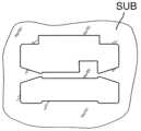
상면도에서, 도 1a 는, 샘플 보디가 격리되도록 된 기판 (SUB) 의 기판 표면 (SO) 의 일부를 도시하고, 상기 샘플 보디는 기판 표면의 일부를 포함한다. 기판 좌표계 (SKS) 는 개선된 배향을 위해 플롯된다. 추후에 TEM 에 의해 검사되도록 된 타겟 체적 (ZV) 은 z-방향으로 기판 표면 (SO) 바로 옆에 인접해 있다. 예시적 경우에, 기판 표면은 평면이고; 그것은 또한 곡선형일 수 있다. 기판 표면의 사전 제조는 일반적으로 불필요하고; 예를 들어, 기판 표면은 연마될 필요가 없다. 예로서, 기판은 다수의 층들로 구성된 반도체 부품일 수 있다.In top view, FIG. 1A shows a part of the substrate surface SO of the substrate SUB from which the sample body is made to be isolated, the sample body comprising a part of the substrate surface. The substrate coordinate system (SKS) is plotted for improved orientation. The target volume (ZV), which is later to be examined by TEM, is immediately adjacent to the substrate surface (SO) in the z-direction. In the exemplary case, the substrate surface is planar; It can also be curved. Pre-fabrication of the substrate surface is generally unnecessary; For example, the substrate surface does not need to be polished. By way of example, the substrate may be a semiconductor component comprised of multiple layers.
매우 자유롭게 선택가능한 샘플 체적은, 레이저 빔의 수직 및 경사 입사 양자에서 레이저 빔 프로세싱에 의해 재료의 연속 삭마에 의해 규정된 위치에서 표면 근접 영역으로부터 릴리스된다. 이를 위해, 추후 홀딩 구조들 (HS1, HS2) 을 구비한 영역들이 먼저 생성된다 (도 1a). 추후에, 제거될 샘플 보디 (PK) 의 기본 구조는 레이저 빔의 부분적으로 수직, 부분적으로 경사 입사 하에 릴리스되고, 상기 샘플 보디만 홀딩 구조들의 영역에서 기판의 잔부에 연결된다 (도 1b 및 도 1c). 그 때까지 생성된 샘플 보디 블랭크가 단지 홀딩 구조들의 영역에서 기판의 잔부에 연결된다.A very freely selectable sample volume is released from the area near the surface at defined positions by continuous ablation of the material by laser beam processing at both normal and oblique incidence of the laser beam. For this purpose, regions with later holding structures (HS1, HS2) are first created (Figure 1a). Later, the basic structure of the sample body PK to be removed is released under a partially vertical, partially oblique incidence of the laser beam, and only the sample body is connected to the remainder of the substrate in the region of the holding structures ( FIGS. 1b and 1c ). The sample body blank produced so far is connected to the remainder of the substrate only in the area of the holding structures.
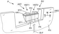
후속 프로세싱 단계들에서, 샘플 보디 블랭크의 중심 부분은, 추가 재료 삭마에 의해, 비슷하게 집속 레이저 빔에 의해 박막화되어서, 타겟 체적 (ZV) 을 포함하는 비교적 좁은 타겟 부분 (ZA) 이 발생한다. 구조적으로 더욱 단단하거나 더욱 두꺼운 부분들이 타겟 부분의 양 종방향 단부들에서 유지되고, 상기 부분들의 영역에서 홀딩 구조들이 샘플 보디의 블랭크에 연결된다. 이 단단한 부분들은 샘플 보디 (PK) 를 추후 핸들링하는 역할을 하여서 본원에서는 핸들링 부분들 (HA1, HA2) 로 나타낸다 (도 1d). 따라서, 이런 식으로 생성된 샘플 보디는 타겟 체적의 영역에서, 즉 타겟 부분에서 작은 두께 뿐만 아니라, 가장자리에서 기계적으로 특히 안정적인 영역들 (핸들링 부분들) 로 특징짓는다.In subsequent processing steps, the central part of the sample body blank is thinned by additional material ablation, similarly by means of a focused laser beam, resulting in a relatively narrow target portion (ZA) comprising the target volume (ZV). Structurally stiffer or thicker parts are held at both longitudinal ends of the target part, in the area of which holding structures are connected to the blank of the sample body. These rigid parts are responsible for subsequent handling of the sample body (PK) and are herein referred to as handling parts (HA1, HA2) (Figure 1d). The sample body produced in this way is therefore characterized by a small thickness in the region of the target volume, i.e. in the target part, as well as mechanically particularly stable regions (handling parts) at the edges.
샘플 보디는 전체 레이저 프로세싱 중 대향한 핸들링 부분들에 인접한 2 개의 홀딩 구조들 (HS1, HS2) 에 의해 단지 홀딩되고, 상기 홀딩 구조들은 샘플 보디를 향해 웨지 형상으로 테이퍼링되고 각각의 경우에 더욱 두꺼운 핸들링 부분들로의 천이부에서 미리 정해진 파괴 지점을 형성한다. 홀딩 웨브들에 의해 샘플 보디를 홀딩함으로써, 프로세싱의 이 단계들 중, 샘플 보디를 송풍시켜 제거하지 않으면서, 압축 공기 또는 가압 하의 그 밖의 다른 가스로 상기 잔류물을 송풍시켜 제거함으로써 레이저 프로세싱의 임의의 프로세싱 잔류물 (잔해) 을 세정할 수 있다. 도 1d 에서 평면도로 도시된 구성은 도 2 의 경사 사시도로 또한 도시된다.The sample body is simply held by two holding structures (HS1, HS2) adjacent to opposing handling parts during the entire laser processing, which taper towards the sample body in a wedge shape and in each case have a thicker handling structure. The transitions to the parts form predetermined failure points. By holding the sample body by holding webs, the residue can be removed by blowing it out with compressed air or any other gas under pressure, without blowing the sample body out during these steps of processing. Processing residues (debris) can be cleaned. The configuration shown in plan view in FIG. 1D is also shown in oblique perspective in FIG. 2 .
추가 프로세싱 단계들이, 홀딩 구조들에 의해 기판에서 홀딩되는 샘플 보디에서 뒤따를 수 있다. 특히, 도 1e 에 도시된 대로, 결과적으로 생긴 샘플 보디는 L-형상과 단지 단일의 단단한 핸들링 부분, 및 그것에 인접한, 얇은 타겟 부분을 가지도록 레이저 프로세싱에 의해 단단한 핸들링 부분들 중 하나를 여전히 제거할 수 있고, 상기 홀딩 구조들 중 하나는 핸들링 부분과 접촉하고 대향한 홀딩 구조는 타겟 부분과 접촉한다. 그렇게 생성된 샘플 보디는 그 후 추가 레이저 프로세싱을 통하여 타겟 부분의 영역에서 추가로 박막화될 수 있다 (도 1f).Additional processing steps may follow with the sample body held on the substrate by holding structures. In particular, as shown in Figure 1e, one of the hard handling parts can still be removed by laser processing such that the resulting sample body has an L-shape and only a single hard handling part, and adjacent to it, a thin target part. One of the holding structures may be in contact with the handling portion and the opposite holding structure may be in contact with the target portion. The sample body thus created can then be further thinned in the region of the target portion through additional laser processing (Figure 1f).
이런 식으로 레이저에 의해 마이크로 프로세싱된 샘플 보디는, 그 후, 예를 들어 종래의 핀셋들, 예컨대 역작용 핀셋들을 사용해 추가 방법 단계에서 기판으로부터 제거될 수 있다. 여기에서, 사용자는 단지 핸들링 부분과 접촉할 것이고 보다 얇은 타겟 부분과 접촉하지 않을 것이다. 샘플 보디는 미리 정해진 파괴 지점들의 영역에서 홀딩 구조들 (HS1, HS2) 의 가장 얇은 위치들에서 잔류 기판으로부터 파괴될 수 있고 그것은 그 후 추가 핸들링을 위해 자유롭다.The sample body microprocessed by the laser in this way can then be removed from the substrate in a further method step, for example using conventional tweezers, such as counter-action tweezers. Here, the user will only contact the handling part and not the thinner target part. The sample body can be broken from the remaining substrate at the thinnest positions of the holding structures (HS1, HS2) in the area of predetermined fracture points and it is then free for further handling.
전술한 방법 단계들을 수행하기에 적합한 레이저 프로세싱 디바이스는, 기판으로 향하는 집속 레이저 빔을 발생시킬 수 있고 미리 프로그램가능한 궤도들을 따라 레이저 빔을 가이드할 수 있도록 레이저, 검류계 스캐너 및 포커싱 광학계를 갖는다. 또한, 레이저 빔과 기판 사이에서 제어가능한 상대 운동을 가능하게 하는 다른 위치결정 유닛들을 구비한 레이저 프로세싱 디바이스들을 사용할 수 있다. 샘플 보디가 제거될 기판은 가공물 리셉터클에 수용된다. 필요시, 가공물 리셉터클은 후 프로세싱을 위해 홀더와 교환될 수 있다. 또한, 가공물 리셉터클은, 각각의 입사 지점에 대해 자유롭게 프로그램가능하게 레이저 빔의 입사 각도 및 입사 방향을 설정할 수 있도록 축선 둘레에서 틸팅되고 그것에 독립적으로 축선 둘레에서 회전될 수 있다. 더욱이, 타겟 위치는 기판의 xy-변위에 의하여 가공물 리셉터클의 편심 (eucentric) 틸트 축선에 정확히 위치결정될 수 있다. 레이저 프로세싱 디바이스는 또한 팬 시스템 및 흡입 시스템을 갖추고 있다. 팬 시스템은, 프로세싱 잔류물이 기판의 프로세싱된 잔부에 침적될 수 없도록 압축 가스의 보조로 발생하는 프로세싱 잔류물을 운반하도록 레이저 빔에 의해 현재 프로세싱되는 영역으로 송풍하는데 사용될 수 있다. 흡입 시스템을 사용해, 프로세싱 잔류물은 환경적으로 상용가능하게 흡입될 수 있다. 또한, 몇 마이크로미터의 정확도로 각각의 타겟 위치를 타겟 삼는데 사용될 수 있는 디지털 카메라를 구비한 관찰 장치가 제공된다. 프로그래밍과 작동은, 레이저 프로세싱 디바이스의 중앙 제어부를 또한 포함하는 작동 유닛에서 소프트웨어 인터페이스에 의해 수행된다.A laser processing device suitable for performing the above-described method steps has a laser, a galvanometer scanner and focusing optics to be able to generate a focused laser beam towards the substrate and to guide the laser beam along pre-programmable trajectories. It is also possible to use laser processing devices with other positioning units that enable controllable relative movement between the laser beam and the substrate. The substrate from which the sample body is to be removed is received in a workpiece receptacle. If necessary, the workpiece receptacle can be exchanged with the holder for post-processing. Additionally, the workpiece receptacle can be tilted about and rotated about the axis independently thereof so as to be able to freely programmably set the angle and direction of incidence of the laser beam for each point of incidence. Moreover, the target position can be positioned precisely on the eucentric tilt axis of the workpiece receptacle by means of the xy-displacement of the substrate. The laser processing device is also equipped with a fan system and a suction system. A fan system can be used to blow through the area currently being processed by the laser beam to transport the resulting processing residue with the assistance of compressed gas so that the processing residue cannot be deposited on the processed remainder of the substrate. Using a suction system, processing residues can be suctioned in an environmentally compatible manner. Additionally, a viewing device equipped with a digital camera is provided that can be used to target each target location with an accuracy of a few micrometers. Programming and operation are performed by means of a software interface in an operating unit which also includes a central control of the laser processing device.
레이저 프로세싱의 범위 내에서, 샘플 보디 홀더는 QM 시스템들의 범위 내에서, 예를 들어 샘플 지정, 연속 번호 또는 매트릭스 코드 또는 바코드로 추적될 수 있도록 마킹될 수 있다.Within the scope of laser processing, the sample body holder can be marked so that it can be traced within the scope of QM systems, for example with a sample designation, serial number or matrix code or barcode.
도 1 을 기반으로 예시적으로 나타낸 프로세싱 전략은 샘플 보디의 신속하고 경제적인 제조라는 의미에서 이런 기구 기반의 가능성들을 이용한다. 비파괴 표면을 갖는 기판 (SUB) 에서 진행할 때, 도 1a 에 도시된 프로세싱 상태는, 대략 직육면체 또는 다각형으로 구획된 체적 영역들 (VOL) 이 기판 재료로부터 제거되도록 레이저 빔 프로세싱에 의해 제거될 체적 영역들에서 사행식 궤도 (TR) 를 따라 검류계 스캐너에 의해 집속 레이저 빔을 가이드시킴으로써 (또는 다른 스캐닝 운동, 예컨대 직선 전진에 의해) 달성된다. 체적 영역들의 폭 (B) (결합 측면들에 수직으로 측정) 은 레이저 빔 절단 경로의 폭의 배수에 대응한다. 예로서, 폭 (B) 은 200 ㎛ ~ 400 ㎛ 의 범위에 있을 수 있다. 결과적으로, 큰 자유 공간들이 노출된 측면들에 인접하여 발생하고 이것은 비송풍 (blowing-free) 에 의해 세정을 단순화시키고 후속 핸들링의 범위 내에서 제거될 샘플 보디에 대한 단순화된 접근을 또한 제공한다. 대규모 노출은 매우 높은 표면 품질을 가지는 측면들을 생성할 수 있도록 한다. 프로세싱 전략 (예컨대 사행식, 박스들, 라인들 등에 의해) 은 노출된 측면들의 품질에 큰 영향을 미친다. 측면들은 일반적으로 레이저 절단 경로의 플랭크 면들보다 훨씬 더 평활하다.The processing strategy shown by way of example based on Figure 1 exploits these tool-based possibilities in the sense of rapid and economical manufacturing of sample bodies. When proceeding on a substrate with a non-destructive surface (SUB), the processing state shown in FIG. 1A is the volume regions to be removed by laser beam processing such that volume regions (VOL) defined as approximately cuboids or polygons are removed from the substrate material. This is achieved by guiding the focused laser beam by a galvanometer scanner (or by another scanning movement, such as straight forward) along a tortuous trajectory (TR). The width (B) of the volumetric regions (measured perpendicular to the joining sides) corresponds to a multiple of the width of the laser beam cutting path. By way of example, the width B may range from 200 μm to 400 μm. As a result, large free spaces arise adjacent to the exposed sides, which simplifies cleaning by blowing-free and also provides simplified access to the sample body to be removed within the scope of subsequent handling. Large-scale exposure allows the creation of aspects with very high surface quality. The processing strategy (eg by meandering, boxes, lines, etc.) has a great influence on the quality of the exposed sides. The sides are generally much smoother than the flank faces of the laser cutting path.
이 단계에서, 작업은 레이저 빔의 거의 수직 입사로, 즉 기판의 법선면에 대략 평행한 레이저 빔의 입사 방향 (z-방향) 으로 수행된다. 샘플 표면에 수직인 측면이 집속 레이저 빔에 의해 생성되도록 되어 있다면, (몇 도 만큼의) 약간의 카운터-틸트가 플랭크 각도를 보상하기 위해서 구상된 방식으로 요구된다.At this stage, the operation is performed with an almost normal incidence of the laser beam, i.e. with the direction of incidence of the laser beam (z-direction) approximately parallel to the normal plane of the substrate. If the side perpendicular to the sample surface is to be produced by the focused laser beam, a slight counter-tilt (of the order of a few degrees) is required in a designed way to compensate for the flank angle.
추후에, 격리될 샘플 보디의 y-방향으로 서로 대향하여 놓여 있는 측면들은, 레이저 빔의 경사 및 수직 입사의 경우 기판 재료의 대응하는 직사각형 체적들을 카브 아웃 (carved out) 함으로써 카브 아웃된다. 도 1b 및 도 1c 는 서로에 대해 90° 만큼 회전한 배향들에서 동일한 프로세싱 상태를 도시한다. 도 1c 와 관련해서, 비대칭 프리즘의 형태를 가지는 샘플 보디를 제공하기 위해서 릴리스될 샘플 보디의 종방향 측면들 (x-방향에 평행하게 연장) 에서 레이저 빔의 경사 입사로 작업이 수행되었음이 쉽게 알 수 있다. 여기에서, 제 1 측면 또는 플랭크 면 (S1) 은 기판 표면에 수직으로 연장되고; 대향한 평면인 제 2 측면 (S2) 은 언더컷 방식으로 기판 표면에 대해 비스듬히 연장된다. 각각의 경우에 평면인 2 개의 측면들 (S1, S2) 은, 기판 표면에 수직으로 측정된 기판 두께의 일부분에 단지 대응하는 깊이로 기판 내부에서 기판 표면 아래에 떨어져 교차한다. 따라서, 기판이 전체 두께에 대해 분리될 필요 없이 샘플 보디는 표면에 가까운 영역으로부터 또한 격리될 수 있다.Later, the sides lying opposite each other in the y-direction of the sample body to be isolated are carved out by carving out the corresponding rectangular volumes of the substrate material in case of oblique and normal incidence of the laser beam. Figures 1b and 1c show the same processing state in orientations rotated by 90° with respect to each other. With reference to Figure 1c, it is easy to see that the operation was carried out with an oblique incidence of the laser beam on the longitudinal sides (extending parallel to the x-direction) of the sample body to be released in order to provide a sample body with the shape of an asymmetric prism. You can. Here, the first side or flank surface (S1) extends perpendicular to the substrate surface; The second side S2, which is an opposing plane, extends obliquely with respect to the substrate surface in an undercut manner. The two sides (S1, S2), which in each case are planar, intersect apart inside the substrate below the substrate surface at a depth corresponding only to a fraction of the substrate thickness measured perpendicular to the substrate surface. Accordingly, the sample body can also be isolated from the area close to the surface without the substrate needing to be separated for the entire thickness.
도 1c 에 도시된 상황은, 샘플 보디가 제거하기 위해 제공된 후속 설계를 아직 획득하지 않은 프로세싱 중간 스테이지를 나타낸다. 추후에, 도 2 에서도 나타낸, 도 1d 에 도시된 덤벨 형태의 샘플 보디가 발생하도록 거의 수직 빔 입사를 갖는 레이저 빔 프로세싱이 기판 재료를 제거하는데 사용됨으로써 샘플 보디는 외부 홀딩 구조들 사이 중심 부분에서 y-방향으로 추가로 박막화된다. 샘플 보디 (PK) 는 이제 제 1 홀딩 구조 (HS1) 에 인접한 제 1 핸들링 부분 (HA1), 대향한 제 2 홀딩 구조 (HS2) 에 인접한 제 2 핸들링 부분 (HA2), 및 핸들링 부분들 사이에, 비교시 더 얇고 타겟 체적 (ZV) 이 놓여 있는 타겟 부분 (ZA) 을 갖는다. 이 평면도에서 C-형상으로 나타나는 샘플 보디 상단측 (PO) 은 이 경우에 기판 표면 (SO) 의 대응하여 형성된 부분에 의해 형성된다.The situation shown in Figure 1C represents an intermediate stage of processing where the sample body has not yet obtained the subsequent design provided for removal. Later, laser beam processing with a nearly vertical beam incidence is used to remove the substrate material to generate the dumbbell-shaped sample body shown in FIG. 1D, also shown in FIG. 2, such that the sample body is It is further thinned in the -direction. The sample body PK now has a first handling part HA1 adjacent to the first holding structure HS1, a second handling part HA2 adjacent to the opposing second holding structure HS2, and between the handling parts, It is thinner in comparison and has a target portion (ZA) on which the target volume (ZV) lies. The sample body top side (PO), which appears C-shaped in this plan view, is in this case formed by a correspondingly formed part of the substrate surface (SO).
평면인 제 1 측면 (S1) 은 샘플 보디 상단측에 수직이고 기판의 z-방향으로 연장된다. 타겟 부분 (ZA) 이 평면인 평행한 플레이트의 형태를 가지도록 대향한 측면 (S3) 은 제 1 측면 (S1) 에 평행하게 연장된다. 측면 (S3) 을 생성하도록 중심 부분을 잘라냄으로써, 직사각형 내각들 (IW) 은 각각의 경우에 타겟 부분 (ZA) 과 인접한 핸들링 부분들 사이 천이부에서 발생하였다. 추후, 내각들의 영역에서 서로에 대해 맞닿아 있는 평면 측면들은 연관된 샘플 보디 홀더에서 샘플 보디의 위치적으로 정확한 고정시 어버트먼트 면들로서 역할을 하고, 어버트먼트 표면들은 x- 및 y-방향으로 정확한 위치결정을 가능하게 한다; 도 3 참조.The first side S1, which is planar, is perpendicular to the top side of the sample body and extends in the z-direction of the substrate. The opposite side S3 extends parallel to the first side S1 so that the target portion ZA has the shape of a planar parallel plate. By cutting off the central part to create the side S3, rectangular internal angles IW were created in each case at the transition between the target part ZA and the adjacent handling parts. Later, the planar sides abutting against each other in the region of the internal angles serve as abutment surfaces in the positionally accurate fixation of the sample body in the associated sample body holder, and the abutment surfaces are oriented in the x- and y-directions. Enables accurate positioning; See Figure 3.
개략적인 도 2 는, 체적 재료에서 기판 상단측의 영역에서 2 개의 박층들 (L1, L2) 을 포함한 기판으로부터 격리된 비슷한 기하학적 구조를 가지는 샘플 보디 (PK) 의 도면을 도시하고, 박층들은 표면과 평행한 계면 (G1) 에 의해 분리되어 있다. y-방향으로 기판 상단측에 평행하게 측정된 타겟 부분의 두께가 충분히 감소되는 경우에, 계면 (G1) 및 인접한 층들 (화살표) 에 실질적으로 평행하게 연장되는, 관찰 방향 (BR) 으로 계면 (G1) 및 인접한 층들 (L1, L2) 의 검사가 가능하도록 얇은 타겟 부분 (ZA) 이 전자의 기판 표면에 수직으로 정렬되는 것을 알 수 있다. 따라서, 단면 제조는 상기 방법에 의해 쉽게 가능하다.Figure 2 schematically shows a diagram of a sample body (PK) with similar geometry isolated from the substrate comprising two thin layers (L1, L2) in the area on the top side of the substrate in volumetric material, the thin layers being connected to the surface and They are separated by a parallel interface (G1). When the thickness of the target portion measured parallel to the top side of the substrate in the y-direction is sufficiently reduced, the interface G1 in the viewing direction BR extends substantially parallel to the interface G1 and the adjacent layers (arrows). ) and the thin target portion (ZA) can be seen to be aligned perpendicular to the former substrate surface to enable inspection of adjacent layers (L1, L2). Therefore, cross-sectional manufacturing is easily possible by the above method.
이미 전술한 대로, 샘플 보디가 기판으로부터 분리되기 전 샘플 보디가 여전히 기판에서 홀딩될 때 타겟 부분은 이미 매우 얇은 전체 두께 (D) 로 박막화될 수 있다.As already mentioned above, the target part can already be thinned to a very thin overall thickness D before it is separated from the substrate while the sample body is still held on the substrate.
핸들링 부분과 타겟 부분의 다음과 같은 전형적인 치수들이 특히 알맞은 것으로 발견되었다. 편차가 가능하다. 후속 프로세싱 단계들이 가능한 한 적은 시간을 요구하도록 타겟 부분은 가능한 한 얇아야 한다. 대략 40 ㎛ 까지의 전체 두께 (D) 가 상시 가능한 것 같고; 최소 두께는 재료에 따라 가변될 수 있다. 동일한 방향 (y-방향) 으로 측정했을 때 핸들링 부분들의 두께는 대개 수 배 더 크고 마찬가지로 재료 의존 방식으로 최적화될 수 있다. 두께는, 특히, 기판 재료의 강도에 의존한다. 실리콘 및 다른 반도체 재료들에 대해, 핸들링 부분은 예컨대 적어도 200 ㎛ 두께이어야 하고, x-방향으로 두께 또는 길이는 동위의 크기를 가질 수 있다. 사파이어 (Al2O3) 와 같은 더 큰 강도를 가지는 재료들에 대해, y-방향으로 100 ㎛ ~ 150 ㎛ 의 두께가 충분할 수도 있다.The following typical dimensions of the handling and target sections were found to be particularly suitable. Deviations are possible. The target part should be as thin as possible so that subsequent processing steps require as little time as possible. Total thicknesses (D) of up to approximately 40 μm appear to be always possible; Minimum thickness may vary depending on the material. The thickness of the handling parts when measured in the same direction (y-direction) is usually several times larger and can likewise be optimized in a material-dependent manner. The thickness depends, inter alia, on the strength of the substrate material. For silicon and other semiconductor materials, the handling part should, for example, be at least 200 μm thick and may be of equal magnitude in thickness or length in the x-direction. For materials with greater strength, such as sapphire (Al2 O3 ), a thickness of 100 μm to 150 μm in the y-direction may be sufficient.
설명한 예시적 실시형태에서, 아직 완전히 박막화되지 않은 타겟 부분을 갖는 샘플 보디 (PK) 가 기판으로부터 제거되고 샘플 보디 기하학적 구조에 특히 적합화된 샘플 보디 홀더 (PH) 에서 규정된 수용 위치에 부착된다 (도 3 참조).In the described exemplary embodiment, the sample body (PK) with a target part that is not yet fully thinned is removed from the substrate and attached to a defined receiving position in a sample body holder (PH) that is particularly adapted to the sample body geometry ( see Figure 3).
예시적 실시형태의 샘플 보디 홀더 (PH) 는, 샘플 보디의 기하학적 구조에 꼭 맞도록 금속 재료 (예컨대 티타늄) 의 얇은 필름으로 레이저 프로세싱에 의해 제조된 일체형의 평평한 기능 요소이다. 일반적으로 플레이트-형상의 샘플 보디 홀더 (PH) 는 대략 반원의 기본 형상을 가지고 (도 5 참조), 그것의 원-반할측에 직사각형 리세스 (AU) (또는 다른 설계를 가지는 리세스) 가 형성된다. 대향한 아치형 측에, 2 개의 삼각형 리세스들 (A1, A2) 이 서로 대향하여 놓여 제공되고, 상기 리세스들은 서로 수직으로 정렬된 2 개의 가장자리들에 의해 구획된다. 이 기하학적 구조는, 추가 프로세싱 단계들에 사용될 수 있는 클램프 마운팅 (여기에서 더이상 상세히 설명되지 않음) 에서 샘플 보디 홀더 또는 전체 샘플의 위치적으로 정확한 부착을 단순화시킨다. 이 점에 있어서, 샘플 홀더의 기하학적 구조는, 이 리세스들의 기능과 함께 EP 2787338 A1 에서 설명된 샘플들의 기하학적 구조와 유사하다. 이 점에 있어서, 그것의 설명이 참조된다.The sample body holder (PH) of the exemplary embodiment is a one-piece, flat functional element manufactured by laser processing from a thin film of a metallic material (eg titanium) to fit snugly to the geometry of the sample body. Typically, the plate-shaped sample body holder (PH) has a basic shape of approximately a semicircle (see Figure 5), with a rectangular recess (AU) (or a recess of other design) formed on its half-circle side. do. On the opposite arcuate side, two triangular recesses (A1, A2) are provided lying opposite each other, the recesses being demarcated by two edges aligned perpendicularly to each other. This geometry simplifies the positionally accurate attachment of the sample body holder or the entire sample in clamp mounting (not described in further detail here), which can be used for further processing steps. In this respect, the geometry of the sample holder, together with the function of these recesses, is similar to the geometry of the samples described in EP 2787338 A1. In this regard, reference is made to its description.
수용 구조들 (AST) 은 상단측에서 리세스 (AU) 의 영역에서 중심에 카브 아웃되었고, 상기 수용 구조들은, 샘플 보디 홀더 상의 홀더 좌표계 (HKS) 면에서 정확히 규정된 수용 위치에, 구조 면에서 적합화된 샘플 보디 (PK) 를 수용할 수 있도록 한다. 예시적 경우에, 수용 구조들 (AST) 은 샘플 보디를 부착하기 위해 2 개의 홀딩 웨브들 (HST1, HST2) 을 포함하고, 상기 홀딩 웨브들은 각각 L-형상의 설계를 가지고 중심 평면에 대해 거울 대칭으로 배치된다. 홀딩 웨브들 (HST1, HST2) 각각은, 도시된 구성에서 수직이고, 단단한 부분으로부터 돌출하고, 자유 단부에, 직각으로 더 짧은 제 2 웨브 부분 (ST2) 을 지지하는 제 1 웨브 부분 (ST1) 을 가지고, 상기 제 2 웨브 부분은 다른 홀딩 웨브와 대면하지 않은 측을 향하여 바깥쪽으로 돌출해 있다. 웨브 부분들 (ST1, ST2) 은 각각 직사각형 단면을 가지고 서로에 대해 직각을 이룬다.Receiving structures (AST) were centrally carved out in the area of the recess (AU) on the upper side, said receiving structures being located at precisely defined receiving positions in the plane of the holder coordinate system (HKS) on the sample body holder, in the structural plane. To accommodate a customized sample body (PK). In an exemplary case, the receiving structures (AST) comprise two holding webs (HST1, HST2) for attaching the sample body, each of which has an L-shaped design and is mirror symmetrical about the central plane. is placed as Each of the holding webs (HST1, HST2) is vertical in the configuration shown, has a first web portion (ST1) projecting from the rigid portion and, at its free end, supports a second web portion (ST2) that is at right angles shorter. wherein the second web portion protrudes outward toward the side that does not face the other holding web. The web portions ST1, ST2 each have a rectangular cross-section and are perpendicular to each other.
여기에 미도시된 변형예에서, 각각의 경우에 제 1 웨브 부분에 평행한 제 3 웨브 부분이 여전히 존재하고, 웨브 부분들이 직사각형 아이 또는 직사각형 개구를 구비한 아이를 형성하도록 상기 제 3 웨브 부분은 외측에서 제 2 웨브 부분에 인접해 있다.In a variant not shown here, in each case there is still a third web portion parallel to the first web portion, said third web portion being such that the web portions form a rectangular eye or an eye with a rectangular opening. Adjacent to the second web portion on the outside.
측 방향 (y-방향) 으로 홀딩 웨브들로 밀려진 후 x-방향으로 작은 유극을 가지고 샘플 보디가 홀딩 웨브들에 안착되도록 서로 대면하지 않은 수직 제 1 웨브 부분들 (ST1) 의 외부측들의 측방향 거리 (x-방향) 는 서로 대면하는 핸들링 부분들 (HA1, HA2) 의 측면들 사이 순간격 (clear distance) 보다 수십 ㎛ (예컨대 최대 50 ㎛) 만큼 더 작고 상기 샘플 보디는, 그것의 내부측으로, y-방향으로 홀딩 웨브들에 맞닿을 수 있다. 외향 돌출한 더 짧은 제 2 웨브 부분들 (ST2) 은 제 1 웨브 부분들 (ST1) 의 종방향 (즉 z-방향) 으로 어버트먼트 면을 형성하고, 상기 어버트먼트 면에 대해 샘플 보디는 샘플 보디 상단측 (PO) 으로 맞닿을 수 있다. 그러므로, 샘플 보디의 수용 위치는 홀딩 웨브들에서 스톱들에 의해 y-방향 및 수직 방향 (z-방향) 으로 규정된다.The outer sides of the vertical first web portions ST1 that do not face each other such that the sample body is seated on the holding webs with a small gap in the x-direction after being pushed onto the holding webs in the lateral direction (y-direction). The directional distance (x-direction) is smaller than the clear distance between the sides of the handling parts (HA1, HA2) facing each other by several tens of μm (e.g. at most 50 μm) and the sample body is moved to its inner side. , can abut the holding webs in the y-direction. The outwardly projecting shorter second web portions ST2 form an abutment face in the longitudinal direction (i.e. z-direction) of the first web portions ST1, with respect to which the sample body It can be contacted with the upper side (PO) of the sample body. Therefore, the receiving position of the sample body is defined in the y-direction and the vertical direction (z-direction) by stops in the holding webs.
이 경우에, 비록 강제적이지는 않지만, 2 개의 단단한 핸들링 부분들이 서로 측방향으로 떨어져 놓여 있고 내면 또는 내부 플랭크가 표면에 수직인 샘플 보디 기하학적 구조가 특히 유리한데, 왜냐하면 이것은 명확하게 샘플 보디 홀더 (PH) 의 2 개의 홀딩 웨브들 (HST1, HST2) 을 따라 대응하는 스톱들로 가이드될 수 있기 때문이다. 샘플 보디를 부착하기 전, 서로 접촉하게 될 샘플 보디 (PK) 및/또는 홀딩 웨브들 (HST1, HST2) 의 면들의 부분들은 접착제에 의해 적셔진다. 매우 내구성 있고 깨끗한 접착 본드가 최소량의 적합한 접착제를 사용해 획득될 수 있도록 샘플 보디가 부착될 때 접착제는 샘플 보디와 홀딩 웨브들 사이의 실질적으로 단지 긴밀한 접촉 영역에만 분배된다.In this case, although not mandatory, a sample body geometry in which the two rigid handling parts lie laterally apart from each other and the inner surface or inner flank is perpendicular to the surface is particularly advantageous, since this clearly allows the sample body holder (PH This is because it can be guided to the corresponding stops along the two holding webs (HST1, HST2) of ). Before attaching the sample body, the parts of the faces of the sample body (PK) and/or the holding webs (HST1, HST2) that will come into contact with each other are wetted with adhesive. When the sample body is attached, the adhesive is distributed substantially only to the intimate contact areas between the sample body and the holding webs so that a very durable and clean adhesive bond can be obtained using a minimum amount of suitable adhesive.
샘플 보디를 기판으로부터 제거할 때와 샘플 보디 홀더의 수용 구조들의 홀딩 웨브들에서 샘플 보디를 부착할 때, 기계적으로 안정적인 핸들링 부분들 (HA1, HA2) 은 단순 입체 광학 현미경으로 관찰 하에 샘플 보디가 핀셋들로 조작될 수 있도록 허용한다.When removing the sample body from the substrate and attaching the sample body to the holding webs of the receiving structures of the sample body holder, the mechanically stable handling parts (HA1, HA2) ensure that the sample body is held with tweezers under observation with a simple stereoscopic optical microscope. allow them to be manipulated.
레이저 프로세싱, 기판 (SUB) 으로부터 샘플 보디 홀더 (PH) 로 샘플 보디 (PK) 의 이송 및 샘플 보디 홀더에 대한 고정을 포함하는, 완전 세트의 프로세싱 단계들을 위해 주위 분위기에 특별한 요구사항은 없고, 따라서 이 단계들은 일반적인 실험실 분위기에서 착수될 수 있다. 특히, 여기에서는 진공에서 작업은 요구되지 않는다.There are no special requirements on the ambient atmosphere for the complete set of processing steps, including laser processing, transfer of the sample body (PK) from the substrate (SUB) to the sample body holder (PH) and fixation on the sample body holder, and therefore These steps can be undertaken in a normal laboratory atmosphere. In particular, working in vacuum is not required here.
도 3 은, 실질적으로 (접착 재료 제외) 단지 샘플 보디 홀더 (PH) 및 상기 홀더에 부착된 샘플 보디 (PK) 로 구성되는 2 부분 설계를 가지는 샘플 (P) 을 도시한다. 이 샘플은 그 후 추가 프로세싱 단계들로 공급될 수 있다. 특히, 샘플 보디 홀더에서 샘플 보디의 고정이 완료된 후, 위에서 실질적으로 수직으로 레이저 빔 프로세싱에 의해 예컨대 대략 10 ㎛ 두께의 웨브 두께로 (y-방향으로 측정) 타겟 부분 (ZA) 을 후에 정확히 박막화하도록 샘플은 특별한 클램프 마운팅으로 이송될 수 있다. 이론상, 샘플 보디가 여전히 기판에서 홀딩될 때 이런 박막화를 다시 수행할 수 있지만, 이렇게 다시 박막화하는 것은 편리하게도 단지 샘플 보디 (PK) 를 샘플 보디 홀더 (PH) 에 체결한 후 일어나야 하는데 왜냐하면 이것은 프로세싱 잔류물 (잔해) 의 즉각적인 배출을 위한 필요한 기하학적 경계 조건들이 특히 간단하고 신뢰성 있게 획득될 수 있도록 허용하고, 다른 경우에는, 기판으로부터 샘플 보디 홀더로 이송하는데 필요한 안정성이 또한 상실될 가능성도 있기 때문이다.Figure 3 shows a sample (P) with a two-part design consisting essentially of only a sample body holder (PH) (excluding adhesive material) and a sample body (PK) attached to the holder. This sample can then be fed into further processing steps. In particular, after the fixation of the sample body in the sample body holder is completed, the target portion ZA is later precisely thinned out, for example to a web thickness of approximately 10 μm thick (measured in the y-direction) by laser beam processing substantially vertically from above. Samples can be transported with special clamp mountings. In theory, this re-thinning could be performed while the sample body is still held on the substrate, but this re-thinning conveniently should only occur after fastening the sample body (PK) to the sample body holder (PH), since this saves processing residues. This allows the necessary geometrical boundary conditions for the immediate discharge of water (debris) to be obtained particularly simply and reliably, since in other cases the stability necessary for transfer from the substrate to the sample body holder is also likely to be lost.
타겟 부분 (ZA) 을 박막화하기 위해 그리고 타겟 체적을 많이 노출시키기 위해 레이저 프로세싱의 마지막 단계들에 초단파 펄스 레이저가 바람직하게 이용된다. 이것에 대한 결과로서, 노출된 플랭크들에 대한 충분한 손상 결여가 획득될 수 있고, 그 결과 이온 빔에 의해 단지 적고, 그리하여 시간 절약되는 후 프로세싱이 필요하게 된다. 선택적으로, 단 펄스 레이저들을 또한 이용할 수 있다. 일반적으로, 안정성 때문에 손상 두께가 임의의 경우에 삭마될 재료 층보다 더 크지 않도록 레이저 유형이 선택되어야 한다.An ultrashort pulse laser is preferably used in the final stages of laser processing to thin the target portion (ZA) and to expose a large portion of the target volume. As a result of this, a sufficient lack of damage to the exposed flanks can be obtained, with the result that only less, and thus time-saving, post-processing with the ion beam is required. Optionally, short pulse lasers can also be used. In general, for stability reasons, the laser type should be selected such that the damage thickness is in any case no greater than the layer of material to be ablated.
예시적으로 도시된 도 3 의 샘플 보디 및 샘플 보디 홀더의 기하학적 구조에서, 전자 투과성에 이르기까지 홀딩 웨브들 사이에서 노출되는 타겟 부분의 최종 후 박막화는 집속 이온 빔 IS-F 의 보조로, 즉 FIB 프로세싱에 의해 타겟 체적의 영역에서 가능하다. 선행 레이저 프로세싱 스테이지들에서 타겟 부분 (ZA) 이 이미 크게 다시 박막화된 상황으로 인해, 손상 결여에 대한 그리고 타겟 정확도에 대한 이 기술의 장점들은, 너무 긴 프로세싱 시간의 단점들을 받아들일 필요 없이 충분히 이용될 수 있다.In the geometry of the sample body and sample body holder exemplarily shown in Figure 3, the final post-thinning of the target portion exposed between the holding webs up to electron transparency is achieved with the assistance of a focused ion beam IS-F, i.e. FIB. Processing is possible in the area of the target volume. Due to the fact that the target area (ZA) has already been significantly re-thinned in previous laser processing stages, the advantages of this technique for lack of damage and for target accuracy can be fully exploited without having to accept the disadvantages of too long processing times. You can.
대안적으로, 후 박막화는 광폭 이온 빔, 즉 보다 광폭이고, 특히 집속되지 않은 이온 빔을 사용해, 예컨대 매우 반응성이 없는 아르곤 이온 또는 다른 비활성 가스 이온으로 또한 수행될 수 있다.Alternatively, post thinning can also be carried out using a wide ion beam, ie a wider, especially unfocused ion beam, for example with highly unreactive argon ions or other noble gas ions.
접착 본딩의 대안으로서, 샘플 보디가 홀딩 웨브들을 벌려줌으로써 홀딩 웨브들 사이에 클램핑될 수 있도록 2 개의 탄성 변형가능한 금속 홀딩 웨브들이 로딩 도구에서 프리텐션될 수 있다. 이 결과, 접착제가 생략될 수 있다. 적절한 설계의 경우, 부분적으로 인터로킹되는 무접착제 래칭 홀드가 또한 가능하다.As an alternative to adhesive bonding, two elastically deformable metal holding webs can be pretensioned in the loading tool so that the sample body can be clamped between the holding webs by spreading them apart. As a result, adhesive can be omitted. With appropriate design, partially interlocking adhesive-free latching holds are also possible.
박막화를 위해 의도되지 않은 영역들의 원치 않는 제거를 회피하기 위해서, 섀도잉이 이 경우에 유리할 수도 있고, 섀도잉은, 와이어 섀도잉의 경우에 공지된 절차에서처럼, 대면적 이온 조사에도 불구하고 국부적으로 정확히 규정된 타겟 체적이 노출될 수 있도록 할 수도 있다.In order to avoid unwanted removal of areas not intended for thinning, shadowing may be advantageous in this case, with shadowing localized despite large-area ion irradiation, as in the known procedure in the case of wire shadowing. It may also allow a precisely defined target volume to be exposed.
도 4 는 샘플 보디 홀더 (PH) 의 실시예를 도시하고, 그것의 수용 구조들 (AST) 은 샘플 보디 상단측에 적합화된 섀도잉 웨브 (ABST) 를 가지고, 상기 섀도잉 웨브는 x-방향으로 연장되고 상기 샘플 보디가 플레이트-형상의 타겟 부분 (ZA) 의 영역에서 홀딩 웨브들에 부착될 때 샘플 보디 (PK) 의 일부, 샘플 보디 상단측 (PO) 을 덮는다. 레이저 프로세싱에 의해 티타늄 필름으로 제조된 샘플 보디 홀더의 경우에, 샘플 보디 홀더의 잔부와 일체로 구현된 섀도잉 웨브는 마찬가지로 티타늄으로 만들어지고, 티타늄은 샘플 보디 (PK) 의 반도체 재료와 비교해 아르곤 이온 충돌 하에 실질적으로 더 낮은 에칭률을 갖는다. 섀도잉 웨브의 재료가 대부분 소모될 때까지 섀도잉 웨브의 재료는 바로 아래에 위치한 타겟 부분의 체적 영역을 이온에 의한 공격으로부터 보호한다. 그 후, (y-방향으로) 적절히 작은 두께를 갖는 타겟 체적이 대부분 에칭된 섀도잉 웨브 아래에서 유지된다면 그리고 이 타겟 체적이 또한 이온에 의해 에칭되기 전 비집속 광폭 이온 빔 (IS-B) 을 이용한 이온 빔 프로세싱이 완료된다. 이런 식으로, 후 박막화를 위해 훨씬 더 비용 효율적으로 생성될 수 있는 광폭 이온 빔을 사용할 때에도, 표면에 가까운 층들을 가지는 단면 샘플들의 타겟 제조가 수행될 수 있다.Figure 4 shows an embodiment of a sample body holder (PH), the receiving structures (AST) of which have a shadowing web (ABST) adapted to the top side of the sample body, the shadowing web extending in the x-direction. and covers a portion of the sample body (PK), the sample body top side (PO), when the sample body is attached to the holding webs in the area of the plate-shaped target portion (ZA). In the case of the sample body holder made of titanium film by laser processing, the shadowing web, which is integrally implemented with the rest of the sample body holder, is likewise made of titanium, and titanium is a source of argon ions compared to the semiconductor material of the sample body (PK). Has a substantially lower etch rate under impact. The material of the shadowing web protects the volumetric area of the target portion located immediately below from attack by ions until most of the material of the shadowing web is consumed. Thereafter, if a target volume with a suitably small thickness (in the y-direction) is maintained mostly below the etched shadowing web and before this target volume is also etched by the ions, an unfocused wide ion beam (IS-B) is applied. Ion beam processing using this is completed. In this way, targeted fabrication of cross-sectional samples with layers close to the surface can be performed, even when using a wide ion beam that can be produced much more cost-effectively for post-thinning.
이온 빔 박막화의 프로세스를 촉진하는 뾰족한 지붕 구조가 발생하도록 레이저 마이크로-프로세싱에 의해 섀도잉 웨브 또는 섀도잉 바의 단면을 변경할 수 있다. 집속 이온 빔에 의한 후 박막화 대신에, 그러면, 이 다음에 광폭 빔 이온 프로세싱 기계를 이용한 이온 빔 프로세싱이 단지 뒤따른다.The cross-section of the shadowing web or shadowing bar can be altered by laser micro-processing to generate a pointed roof structure that facilitates the process of ion beam thinning. Instead of post-thinning with a focused ion beam, this is then simply followed by ion beam processing using a wide beam ion processing machine.
처리량을 더 증가시키도록, 샘플 보디 홀더는 또한 하나보다 많은 수용 구조, 예를 들어 서로 옆에 놓여 있는 2 개의 동일한 수용 구조들 (AST1, AST2) 을 가질 수 있고, 각각은 각각의 경우에 샘플 보디를 수용하도록 도 3 (도 5) 의 수용 구조와 같은 홀딩 웨브들을 갖는다.To further increase throughput, the sample body holder can also have more than one receiving structure, for example two identical receiving structures (AST1, AST2) lying next to each other, each containing a sample body in each case. It has holding webs such as the receiving structure of Figure 3 (Figure 5) to receive.
또한, 쌍을 이루는 상보적 끼워맞춤 피스들 (PS1, PS2) 이 샘플 보디 홀더들의 측면 영역들에서 작동될 수 있고, 상기 끼워맞춤 피스들은, 샘플 보디들이 부착된 상태에서, 샘플 (P) 로서 2 개의 샘플 보디 홀더들 (PH1, PH2) 을 함께 사용할 수 있도록 하고 샘플이 마이크로구조 검사 설비의 대응하는 홀더로, 예컨대 투과형 전자 현미경의 표준 샘플 홀더로 설치될 수 있도록 한다 (도 6 참조). 이런 식으로, 특히, 시일-시스템 시간이 감소되거나 회피될 수 있으므로 제조 효율성 뿐만 아니라 추후 분석 효율성을 높일 수 있다.Additionally, a pair of complementary fitting pieces (PS1, PS2) can be actuated in the lateral regions of the sample body holders, which, with the sample bodies attached, serve as sample (P) 2 It allows the two sample body holders (PH1, PH2) to be used together and allows the sample to be installed into the corresponding holder of a microstructure examination facility, for example as a standard sample holder of a transmission electron microscope (see Figure 6). In this way, in particular, seal-to-system times can be reduced or avoided, thereby increasing not only manufacturing efficiency but also subsequent analysis efficiency.
전술한 실시예들에서 벗어난 다양한 변형예들이 가능하다. 예로서, 핸들링 부분 또는 핸들링 부분들 모두 샘플 보디의 가장자리 또는 단부에 배치될 필요가 없다. 도 7 의 예시적 실시형태에서, 샘플 보디 (PK) 는 2 개의 핸들링 부분들 (HA1, HA2) 을 가지고, 제 1 타겟 부분 (ZA1) 이 쌍을 이룬 핸들링 부분들의 일측에 존재하고 제 2 타겟 부분 (ZA2) 이 대향 측에 존재하도록 상기 핸들링 부분들은 종방향 (x-방향) 으로 대략 샘플 보디의 중심 영역에 배치된다. 따라서, 얇은 플레이트-형상의 타겟 부분들이 샘플 보디의 자유 단부들에 놓여 있고, 그것의 홀딩은 중심 영역에서 일어난다.Various modifications that deviate from the above-described embodiments are possible. By way of example, neither the handling portion nor the handling portions need be disposed at an edge or end of the sample body. In the exemplary embodiment of Figure 7, the sample body PK has two handling portions HA1, HA2, with a first target portion ZA1 being on one side of the paired handling portions and a second target portion The handling parts are arranged approximately in the central region of the sample body in the longitudinal direction (x-direction) so that (ZA2) is on the opposite side. Accordingly, thin plate-shaped target parts lie at the free ends of the sample body, and its holding takes place in the central region.
도 7 에서 이런 형태의 샘플 보디에 적합화된 샘플 보디 홀더 (PH) 는 단일, T-형상의 홀딩 웨브 (HST) 에 의해 형성된 수용 구조들 (AST) 을 갖는다. 이것은 z-방향으로 연장되는 비교적 긴 웨브 부분 (ST1) 을 가지고, 그것의 자유 단부에서 종방향으로 돌출한 보다 짧은 제 2 웨브 부분 (ST2) 이 양측에 형성된다. y-방향으로 유극 없이 샘플 보디가 제 1 웨브 부분 (ST1) 으로 많이 밀릴 수 있도록 2 개의 핸들링 부분들 사이에서 x-방향으로 측정된 순간격은 이 경우에 이 방향으로 측정된 제 1 웨브 부분 (ST1) 의 폭보다 약간 더 크다. y-방향으로 스톱으로서 역할을 하는 중간 부분은 핸들링 부분들 사이에서 타겟 부분들과 동일한 높이로 위치한다. 수직 웨브 부분 (ST2) 은 샘플 보디에 대해 z-방향으로 유효한 상부 스톱을 형성하고, 샘플 보디는 그것의 샘플 보디 상단측 (PO) 으로 상기 스톱에 접하게 놓여 있다. 다른 실시예들에서처럼, 샘플 보디는 접착 본딩에 의해 홀딩 웨브 (HST) 에 체결된다.The sample body holder (PH) adapted for this type of sample body in FIG. 7 has receiving structures (AST) formed by a single, T-shaped holding web (HST). It has a relatively long web portion (ST1) extending in the z-direction, with shorter second web portions (ST2) protruding longitudinally at its free end on both sides. The instantaneous gap measured in the x-direction between the two handling parts allows the sample body to be pushed as far as the first web part (ST1) without play in the y-direction, in this case the first web part ( It is slightly larger than the width of ST1). The middle part, which serves as a stop in the y-direction, is located between the handling parts at the same height as the target parts. The vertical web portion (ST2) forms an effective upper stop in the z-direction relative to the sample body, which lies abutting this stop with its sample body top side (PO). As in other embodiments, the sample body is fastened to the holding web (HST) by adhesive bonding.
도 8 의 변형예에서, 수용 구조들 (AST) 의 홀딩 웨브 (HST) 는 마찬가지로 T 형태를 가지지만, 보다 긴 제 1 웨브 부분 (ST1) 이 이 경우에는 x-방향으로 (도 8 에서 수평으로) 정렬되고, 제 1 웨브 부분에 수직인 크로스바 또는 제 2 웨브 부분 (ST2) 은 z-방향으로 평행하게 정렬된다. 샘플 보디 (PK) 는 2 개의 핸들링 부분들 (HA1, HA2) 을 가지고, 상기 핸들링 부분들은 중간 피스를 통하여 연결되고 상기 핸들링 부분들 사이에 제 1 웨브 부분 (ST2) 의 두께와 동일한 폭을 가지는 간극이 있다. 전체적으로, 쌍을 이룬 핸들링 부분들은 샘플 보디의 단부 영역에 위치하고, 타겟 부분 (ZA) 은 일측에서 다른 단부 영역으로 연장되고, 본 경우에, 타겟 부분은 z-방향에 평행하게 정렬된다. "직립" 정렬을 갖는 이러한 샘플 보디는, 예를 들어, 원자 탐침 단층 촬영 (LEAP) 또는 x 선 단층 촬영/x 선 현미경 관찰을 위한 샘플을 제조하는 역할을 할 수 있다.In the variant of FIG. 8 , the holding web HST of the receiving structures AST likewise has a T shape, but the longer first web portion ST1 is in this case extended in the x-direction (horizontally in FIG. 8 ) is aligned, and the crossbar or second web portion ST2 perpendicular to the first web portion is aligned parallel in the z-direction. The sample body PK has two handling parts HA1, HA2, which are connected via an intermediate piece and a gap between the handling parts having a width equal to the thickness of the first web part ST2. There is. Overall, the paired handling parts are located in the end region of the sample body, with a target part (ZA) extending from one side to the other, in the present case the target part being aligned parallel to the z-direction. This sample body with an “upright” alignment can serve, for example, to prepare samples for atom probe tomography (LEAP) or x-ray tomography/x-ray microscopy.
본 발명의 변형예들의 범위 내에서, 이온 빔 박막화의 마지막 단계는 임의의 유형의 집속 이온 빔 프로세싱 (Ga-이온/플라즈마-FIB) 에 의해 그리고 광폭 빔 이온 에칭에 의해 수행될 수 있음이 분명하다.It is clear that, within the scope of the variants of the invention, the final step of ion beam thinning can be performed by any type of focused ion beam processing (Ga-ion/plasma-FIB) and by wide beam ion etching. .
예컨대 도 4 내지 도 8 에 도시된 대로, 숫자 등의 형태인 마킹들 (MK) 이 예를 들어 개선된 추적을 위해 샘플 보디 홀더로 도입될 수 있다. 이것은 레이저 빔에 의해 쉽게 가능하다.As shown for example in FIGS. 4 to 8 , markings (MK) in the form of numbers etc. can be introduced into the sample body holder, for example for improved tracking. This is easily possible with a laser beam.
본 발명의 일부 양태들은 투과형 전자 현미경 검사를 위한 샘플들의 예를 이용해 설명되었다. 하지만, 본 발명의 용도는 그것에 제한되지 않는다. 많은 다른 마이크로구조 진단 방법들을 위한 샘플들은 마찬가지로 설명한 방법 또는 그것의 변형예들에 따라 제조될 수 있다.Some aspects of the invention have been illustrated using examples of samples for transmission electron microscopy. However, the use of the present invention is not limited thereto. Samples for many other microstructural diagnostic methods can likewise be prepared according to the described method or variations thereof.
예로서, 싱크로트론 방사선 소스들 외측에, 오랫동안 순수한 단층 촬영 섀도우-캐스팅 방법들 (x 선 컴퓨터 단층 촬영) 이었고 최근에 x 선 현미경 관찰로 발달된 x 선을 이용한 촬상 방법들이 사용된다. 후자의 방법 (x 선 현미경 관찰, XRM) 에서는, 2-스테이지 확대가 있다. 여기에서, 후 확대는 섀도우-캐스팅 원리를 따른다. x 선 방사 침투능으로 인해 그리고 샘플이 3D 구조의 고 해상도 검사를 위해 x 선 소스와 검출자 사이에서 회전될 필요가 있는 상황으로 인해, XRM 샘플들의 요건은 그것이 소 직경 (전형적으로: 몇 ~ 수십 ㎛) 을 가지는 것이다. 레이저 마이크로-프로세싱에 의한 제조는 마찬가지로 이를 위해 알맞다.
As an example, outside of synchrotron radiation sources, imaging methods using x-rays are used, which have long been purely tomographic shadow-casting methods (x-ray computed tomography) and have recently developed into x-ray microscopy. In the latter method (x-ray microscopy, XRM), there is a two-stage magnification. Here, post-enlargement follows the shadow-casting principle. Due to the penetrability of x-ray radiation and the situation in which the sample needs to be rotated between the ) is to have. Manufacturing by laser micro-processing is likewise suitable for this.
Claims (15)
Translated fromKorean미리 정할 수 있는 형태를 갖는 샘플 보디 (PK) 는 재료-삭마 레이저 빔 프로세싱을 통하여 기판으로부터 제조되고 추후에 상기 샘플 보디의 타겟 부분 (ZA) 은 마이크로구조 검사에 적합한 타겟 체적 (ZV) 을 노출시키도록 레이저 빔 프로세싱 및/또는 이온 빔 프로세싱을 통하여 추가로 프로세싱되고,
상기 방법은:
(a) 샘플 보디가 발생하도록 기판 표면 (SO) 에 수직으로 적어도 하나의 레이저 빔 그리고/또는 비스듬히 적어도 하나의 레이저 빔을 방사함으로써 적어도 하나의 레이저 프로세싱 작동에 의해 상기 기판으로부터 상기 샘플 보디 (PK) 를 릴리스하는 단계로서, 상기 샘플 보디는 샘플 보디 상단측 (PO) 에서 상기 기판 표면의 영역에 의해, 그리고, 측방향으로, 상기 기판 표면에 대해 비스듬히 또는 수직으로 배향되는 측면들 (S1, S2, S3) 에 의해 구획되고,
(1) 상기 샘플 보디의 형태가 생성되고, 상기 형태는 적어도 하나의 단단한 핸들링 부분 (HA, HA1, HA2), 및 상기 핸들링 부분에 인접한, 상기 핸들링 부분에 비해 더 얇은 타겟 부분 (ZA) 을 가지고, 상기 타겟 부분은 협측 (narrow side) 에서 상기 샘플 보디 상단측 (PO) 에 의해, 그리고, 측방향으로, 상기 샘플 보디 상단측에 대해 수직으로 또는 비스듬히 연장되는 측면들 (S1, S3) 에 의해 구획되고, (2) 상기 타겟 부분 (ZA) 과 인접한 핸들링 부분 (HA1, HA2) 사이에 내각 (IW) 이 발생하도록 상기 샘플 보디 (PK) 가 설계되고, 상기 타겟 부분의 측면 (S3) 과 상기 핸들링 부분 (HA1, HA2) 의 측면은 상기 내각에서 각도를 이루며 교차하는, 상기 기판으로부터 상기 샘플 보디 (PK) 를 릴리스하는 단계;
(b) 상기 샘플 보디와 분리되어 있고 규정된 수용 위치에서 상기 샘플 보디를 수용하기 위해 상기 샘플 보디의 형태에 적합화된 수용 구조들을 가지는 샘플 보디 홀더 (PH) 를 제조하는 단계;
(c) 상기 기판으로부터 릴리스된 상기 샘플 보디를 제거하는 단계;
(d) 상기 기판으로부터 제거된 상기 샘플 보디를 상기 샘플 보디 홀더의 상기 수용 구조들에 부착하는 단계로서, 상기 샘플 보디 홀더에 대한 상기 샘플 보디의 위치가 적어도 2 개의 상호 수직 방향으로 설정되도록 상기 샘플 보디 홀더 (PH) 에 상기 샘플 보디 (PK) 를 부착할 때 서로에 대해 상기 내각 (IW) 을 이루는 2 개의 면들에서 상기 샘플 보디와 상기 샘플 보디 홀더 사이에 규정된 면적 접촉이 발생되는, 상기 샘플 보디를 상기 샘플 보디 홀더의 상기 수용 구조들에 부착하는 단계;
(e) 상기 타겟 체적을 노출하기 위해 레이저 빔 프로세싱 및/또는 이온 빔 프로세싱에 의해 상기 타겟 부분의 영역에서 상기 샘플 보디의 적어도 하나의 측면의 적어도 하나의 추가 재료-삭마 프로세싱 단계를 수행하는 단계를 포함하는, 마이크로구조 진단용 샘플 (P) 을 제조하기 위한 방법.As a method for producing a sample (P) for microstructure diagnosis,
A sample body (PK) with a predetermined shape is fabricated from a substrate through material-ablation laser beam processing and later a target portion (ZA) of the sample body is exposed to a target volume (ZV) suitable for microstructural inspection. further processed through laser beam processing and/or ion beam processing,
The above method is:
(a) separating the sample body (PK) from the substrate by at least one laser processing operation by emitting at least one laser beam perpendicularly and/or at an angle to the substrate surface (SO) to generate the sample body; releasing, wherein the sample body has sides (S1, S2, S3) is partitioned by,
(1) A shape of the sample body is created, the shape having at least one rigid handling part (HA, HA1, HA2), and a target part (ZA) adjacent to the handling part, which is thinner than the handling part. , the target part is by the sample body upper side (PO) in the narrow side and laterally by the sides (S1, S3) extending perpendicularly or obliquely to the sample body upper side. (2) the sample body (PK) is designed such that an internal angle (IW) occurs between the target portion (ZA) and the adjacent handling portions (HA1, HA2), and the side (S3) of the target portion and the releasing the sample body (PK) from the substrate, the sides of the handling portions (HA1, HA2) intersecting at an angle at the inner angle;
(b) manufacturing a sample body holder (PH) separate from the sample body and having receiving structures adapted to the shape of the sample body to receive the sample body in a defined receiving position;
(c) removing the sample body released from the substrate;
(d) attaching the sample body removed from the substrate to the receiving structures of the sample body holder, such that the position of the sample body relative to the sample body holder is set in at least two mutually perpendicular directions. said sample, wherein when attaching said sample body (PK) to a body holder (PH), a defined area contact occurs between said sample body and said sample body holder on two faces forming said inner angle (IW) with respect to each other. attaching a body to the receiving structures of the sample body holder;
(e) performing at least one additional material-ablation processing step of at least one side of the sample body in the region of the target portion by laser beam processing and/or ion beam processing to expose the target volume. A method for producing a sample (P) for microstructure diagnosis, comprising:
상기 샘플 보디 (PK) 는 접착 본딩 또는 클램핑에 의해 상기 수용 구조들 (AST) 에 체결되는 것을 특징으로 하는, 마이크로구조 진단용 샘플 (P) 을 제조하기 위한 방법.According to claim 1,
Method for producing a sample (P) for microstructural diagnosis, characterized in that the sample body (PK) is fastened to the receiving structures (AST) by adhesive bonding or clamping.
제 1 핸들링 부분 (HA1) 및 제 2 핸들링 부분 (HA2) 이 생성되고, 얇은 중간 부분이 상기 제 1 핸들링 부분과 상기 제 2 핸들링 부분 사이에 놓여 있고, 상기 중간 부분은 타겟 부분 (ZA) 으로서 구성되는 것을 특징으로 하는, 마이크로구조 진단용 샘플 (P) 을 제조하기 위한 방법.According to claim 1,
A first handling part (HA1) and a second handling part (HA2) are created, a thin middle part lies between the first handling part and the second handling part, and the middle part is configured as a target part (ZA). A method for producing a microstructure diagnostic sample (P), characterized in that:
기판 재료로 만들어진 홀딩 구조 (HS) 는 릴리스 단계 (a) 중 상기 핸들링 부분의 측면의 적어도 하나의 지점에서 유지되고, 상기 샘플 보디 (PK) 가 상기 홀딩 구조만을 통하여 상기 기판의 잔부에 연결되도록 상기 홀딩 구조는 상기 핸들링 부분 (HA) 의 영역에서 상기 적어도 하나의 지점 이외의 부분은 릴리스되는 샘플 보디와 상기 기판 (SUB) 의 인접 부분을 연결하고, 단계 (c) 에서 상기 샘플 보디의 제거는 상기 홀딩 구조의 영역에서 상기 샘플 보디와 상기 기판 사이 연결을 분리시키는 것을 특징으로 하는, 마이크로구조 진단용 샘플 (P) 을 제조하기 위한 방법.According to claim 1,
A holding structure (HS) made of substrate material is held at at least one point on the side of the handling portion during release step (a), such that the sample body (PK) is connected to the remainder of the substrate only via the holding structure. A holding structure connects an adjacent portion of the sample body and the substrate (SUB), from which a portion other than the at least one point in the region of the handling portion (HA) is released, and the removal of the sample body in step (c) is carried out by: A method for producing a sample (P) for microstructural diagnosis, characterized in that the connection between the sample body and the substrate is separated in the region of the holding structure.
기판 재료로 만들어진 체적 영역 (VOL) 은 릴리스 단계 (a) 의 범위 내에서 상기 레이저 빔 프로세싱 중 상기 측면들 중 적어도 하나에 인접하여 배치되고, 상기 체적 영역은 레이저 빔 절단 경로의 폭의 배수인 측면에 수직인 폭 (B) 을 가지고, 상기 체적 영역의 상기 폭 (B) 은 200 ㎛ 이상, 또는 300 ㎛ ~ 400 ㎛ 의 범위에 있는 것을 특징으로 하는, 마이크로구조 진단용 샘플 (P) 을 제조하기 위한 방법.According to claim 1,
A volumetric area (VOL) made of substrate material is disposed adjacent to at least one of the sides during processing of the laser beam within the scope of the release step (a), wherein the volumetric area is a side that is a multiple of the width of the laser beam cutting path. for producing a sample (P) for microstructure diagnosis, characterized in that the width (B) of the volume area is at least 200 μm, or in the range of 300 μm to 400 μm. method.
상기 체적 영역 (VOL) 은 집속 레이저 빔의 스캐닝 유도에 의해 연속적으로 처리되는 것을 특징으로 하는, 마이크로구조 진단용 샘플 (P) 을 제조하기 위한 방법.According to claim 5,
Method for producing a sample (P) for microstructural diagnosis, characterized in that the volume area (VOL) is continuously processed by scanning guidance of a focused laser beam.
상기 릴리스 단계 (a) 중 상기 기판 표면에 수직으로 측정된 상기 샘플 보디 (PK) 의 크기가 상기 기판 표면에 수직으로 측정된 상기 기판 (SUB) 의 두께보다 작도록 상기 샘플 보디가 생성되고, 서로에 대해 각도를 이루고 서로 대향하여 놓여 있는 2 개의 측면들 (S1, S3) 은 레이저 빔 프로세싱에 의해 중간 단계에서 생성되고, 상기 측면들은 상기 기판의 내부에 놓여있는 교차선에서 교차하는 것을 특징으로 하는, 마이크로구조 진단용 샘플 (P) 을 제조하기 위한 방법.According to claim 1,
During the release step (a), the sample body is created such that the size of the sample body (PK) measured perpendicular to the substrate surface is smaller than the thickness of the substrate (SUB) measured perpendicular to the substrate surface, and Two sides (S1, S3), which lie opposite each other and at an angle with respect to , Method for producing a sample (P) for microstructure diagnosis.
상기 기판 표면의 상기 영역에서, 상기 기판은 계면들 (G1) 에 의해 분리되는 하나 이상의 층들 (L1, L2) 또는 층 세그먼트들을 가지고, 하나 이상의 계면들이 상기 타겟 부분 (ZA) 의 적어도 하나의 측면 (S3) 에 실질적으로 수직으로 배향되도록 상기 샘플 보디가 생성되는 것을 특징으로 하는, 마이크로구조 진단용 샘플 (P) 을 제조하기 위한 방법.The method according to any one of claims 1 to 7,
In this region of the substrate surface, the substrate has one or more layers (L1, L2) or layer segments separated by interfaces (G1), wherein one or more interfaces are located on at least one side of the target portion (ZA) Method for producing a sample (P) for microstructural diagnosis, characterized in that the sample body is produced so that it is oriented substantially perpendicular to S3).
상기 타겟 부분의 측면 (S3) 과 상기 핸들링 부분 (HA1, HA2) 의 측면이 직각으로 교차하는 것을 특징으로 하는, 마이크로구조 진단용 샘플 (P) 을 제조하기 위한 방법.The method according to any one of claims 1 to 7,
A method for producing a sample (P) for microstructure diagnosis, characterized in that the side surface (S3) of the target portion and the side surface of the handling portion (HA1, HA2) intersect at a right angle.
상기 샘플 보디 홀더 (PH) 는 기판 재료와 상이한 홀더 재료로 제조되고,
상기 홀더 재료는 금속을 가지는 것, 또는 상기 샘플 보디 홀더는 상기 홀더 재료의 플레이트 또는 필름으로부터 레이저 프로세싱에 의해 제조되는 것을 특징으로 하는, 마이크로구조 진단용 샘플 (P) 을 제조하기 위한 방법.The method according to any one of claims 1 to 7,
The sample body holder (PH) is made of a holder material different from the substrate material,
The method for producing a sample (P) for microstructural diagnosis, characterized in that the holder material has a metal, or the sample body holder is manufactured by laser processing from a plate or film of the holder material.
상기 수용 구조들 (AST) 은 상기 샘플 보디 (PK) 를 부착하기 위한 하나 이상의 홀딩 웨브들 (HST1, HST2) 을 가지고, 다음의 조건 (i) 및 조건 (ii) 중 적어도 하나가 충족되는 것을 특징으로 하는, 마이크로구조 진단용 샘플 (P) 을 제조하기 위한 방법.
(i) 상기 샘플 보디 (PK) 의 대응하는 측면을 장착하기 위한 적어도 하나의 어버트먼트 면은 홀딩 웨브에서 구현되고, 상기 내각 (IW) 에 적합화된 외각이 홀딩 웨브에 형성되는 조건;
(ⅱ) 홀딩 웨브는 제 1 웨브 부분 (ST1) 및 상기 제 1 웨브 부분에 직각을 이루어 배향되는 제 2 웨브 부분 (ST2) 을 가지고, 상기 홀딩 웨브는 T-형상 또는 L-형상을 가지는 조건The method according to any one of claims 1 to 7,
Said receiving structures (AST) have one or more holding webs (HST1, HST2) for attaching said sample body (PK), characterized in that at least one of the following conditions (i) and (ii) is met: A method for producing a sample (P) for microstructure diagnosis.
(i) at least one abutment face for mounting the corresponding side of the sample body (PK) is implemented in the holding web, and an outer angle adapted to the inner angle (IW) is formed in the holding web;
(ii) the holding web has a first web portion (ST1) and a second web portion (ST2) oriented at right angles to the first web portion, the holding web having a T-shape or an L-shape.
상기 수용 구조들 (AST) 은 상기 샘플 보디 상단측에 적합화된 섀도잉 웨브 (ABST) 를 가지고, 상기 섀도잉 웨브는 이온 조사 및/또는 레이저 조사의 경우 기판 재료보다 낮은 삭마률을 가지는 재료로 구성되는 것을 특징으로 하는, 마이크로구조 진단용 샘플 (P) 을 제조하기 위한 방법.The method according to any one of claims 1 to 7,
The receiving structures (AST) have a shadowing web (ABST) adapted to the upper side of the sample body, the shadowing web being made of a material having a lower ablation rate than the substrate material in the case of ion irradiation and/or laser irradiation. A method for producing a microstructure diagnostic sample (P), characterized in that:
상기 수용 구조들에 상기 샘플 보디를 부착하기 전, 적어도 상기 타겟 부분의 협측 영역에서, 상기 샘플 보디 상단측에 희생층이 적용되고, 상기 희생층은 이온 조사 및/또는 레이저 조사의 경우에 기판 재료보다 낮은 삭마률을 가지는 재료로 구성되는 것을 특징으로 하는, 마이크로구조 진단용 샘플 (P) 을 제조하기 위한 방법.The method according to any one of claims 1 to 7,
Before attaching the sample body to the receiving structures, a sacrificial layer is applied to the top side of the sample body, at least in the buccal region of the target portion, the sacrificial layer being applied to the substrate material in the case of ion irradiation and/or laser irradiation. A method for producing a sample (P) for microstructural diagnosis, characterized in that it consists of a material having a lower ablation rate.
규정된 수용 위치에서 샘플 보디를 수용하기 위한 수용 구조들을 구비한 샘플 보디 홀더 (PH); 및
상기 샘플 보디 홀더와 별도로 제조되는 적어도 하나의 샘플 보디 (PK) 로서, 상기 샘플 보디는 적어도 하나의 단단한 핸들링 부분 (HA, HA1, HA2), 및 상기 핸들링 부분에 인접한, 상기 핸들링 부분에 비해 더 얇은 타겟 부분 (ZA) 을 가지고, 상기 타겟 부분은 협측에서 상기 샘플 보디 상단측 (PO) 에 의해, 그리고, 측방향으로, 상기 샘플 보디 상단측에 대해 수직으로 또는 비스듬히 연장되는 측면들 (S1, S3) 에 의해 구획되고, 상기 타겟 부분 (ZA) 과 인접한 핸들링 부분 (HA1, HA2) 사이에 내각 (IW) 이 발생하도록 상기 샘플 보디 (PK) 가 설계되고, 상기 타겟 부분의 측면 (S3) 과 상기 핸들링 부분 (HA1, HA2) 의 측면은 상기 내각 (IW) 에서 각도를 이루며 교차하고,
상기 샘플 보디는 상기 수용 위치에서 상기 수용 구조들에 부착되고, 서로에 대해 상기 내각 (IW) 을 이루는 2 개의 면들에서 상기 샘플 보디 (PK) 와 상기 샘플 보디 홀더 (PH) 사이에 규정된 면적 접촉이 발생되는, 상기 적어도 하나의 샘플 보디 (PK) 를 포함하는, 마이크로구조 진단용 샘플.A sample for microstructural diagnosis, obtainable or obtained by a method comprising the features of any one of claims 1 to 7,
a sample body holder (PH) with receiving structures for receiving the sample body in a defined receiving position; and
At least one sample body (PK) manufactured separately from the sample body holder, the sample body comprising at least one rigid handling part (HA, HA1, HA2) and adjacent to the handling part, thinner compared to the handling part. Has a target portion (ZA), said target portion having sides (S1, S3) extending buccally by the upper side (PO) of the sample body and laterally, perpendicularly or obliquely to the upper side of the sample body ), and the sample body (PK) is designed so that an internal angle (IW) occurs between the target portion (ZA) and the adjacent handling portions (HA1, HA2), and the side (S3) of the target portion and the The sides of the handling portions (HA1, HA2) intersect at an angle at the inner angle (IW),
The sample body is attached to the receiving structures at the receiving position and has a defined area contact between the sample body (PK) and the sample body holder (PH) on two sides forming the inner angle (IW) with respect to each other. A sample for microstructural diagnosis, comprising said at least one sample body (PK), in which this is generated.
미리 정할 수 있는 형태를 갖는 샘플 보디 (PK) 는 재료-삭마 레이저 빔 프로세싱을 통하여 기판으로부터 제조되고 추후에 상기 샘플 보디의 타겟 부분 (ZA) 은 마이크로구조 검사에 적합한 타겟 체적 (ZV) 을 노출시키도록 레이저 빔 프로세싱 및/또는 이온 빔 프로세싱을 통하여 추가로 프로세싱되고,
상기 방법은:
(a) 샘플 보디가 발생하도록 기판 표면 (SO) 에 수직으로 적어도 하나의 레이저 빔 그리고/또는 비스듬히 적어도 하나의 레이저 빔을 방사함으로써 적어도 하나의 레이저 프로세싱 작동에 의해 상기 기판으로부터 상기 샘플 보디 (PK) 를 릴리스하는 단계로서, 상기 샘플 보디는 샘플 보디 상단측 (PO) 에서 상기 기판 표면의 영역에 의해, 그리고, 측방향으로, 상기 기판 표면에 대해 비스듬히 또는 수직으로 배향되는 측면들 (S1, S2, S3) 에 의해 구획되고,
(1) 상기 샘플 보디의 형태가 생성되고, 상기 형태는 적어도 하나의 단단한 핸들링 부분 (HA, HA1, HA2), 및 상기 핸들링 부분에 인접한, 상기 핸들링 부분에 비해 더 얇은 타겟 부분 (ZA) 을 가지고, 상기 타겟 부분은 협측 (narrow side) 에서 상기 샘플 보디 상단측 (PO) 에 의해, 그리고, 측방향으로, 상기 샘플 보디 상단측에 대해 수직으로 또는 비스듬히 연장되는 측면들 (S1, S3) 에 의해 구획되고, (2) 상기 타겟 부분 (ZA) 과 인접한 핸들링 부분 (HA1, HA2) 사이에 내각 (IW) 이 발생하도록 상기 샘플 보디 (PK) 가 설계되고, 상기 타겟 부분의 측면 (S3) 과 상기 핸들링 부분 (HA1, HA2) 의 측면은 상기 내각에서 각도를 이루며 교차하는, 상기 기판으로부터 상기 샘플 보디 (PK) 를 릴리스하는 단계;
(b) 상기 샘플 보디와 분리되어 있고 규정된 수용 위치에서 상기 샘플 보디를 수용하기 위해 상기 샘플 보디의 형태에 적합화된 수용 구조들을 가지는 샘플 보디 홀더 (PH) 를 제조하는 단계;
(c) 상기 기판으로부터 릴리스된 상기 샘플 보디를 제거하는 단계;
(d) 상기 기판으로부터 제거된 상기 샘플 보디를 상기 샘플 보디 홀더의 상기 수용 구조들에 부착하는 단계로서, 상기 샘플 보디 홀더에 대한 상기 샘플 보디의 위치가 적어도 2 개의 상호 수직 방향으로 설정되도록 상기 샘플 보디 홀더 (PH) 에 상기 샘플 보디 (PK) 를 부착할 때 서로에 대해 각도를 이루는 2 개의 면들에서 상기 샘플 보디와 상기 샘플 보디 홀더 사이에 규정된 면적 접촉이 발생되는, 상기 샘플 보디를 상기 샘플 보디 홀더의 상기 수용 구조들에 부착하는 단계;
(e) 상기 타겟 체적을 노출하기 위해 레이저 빔 프로세싱 및/또는 이온 빔 프로세싱에 의해 상기 타겟 부분의 영역에서 상기 샘플 보디의 적어도 하나의 측면의 적어도 하나의 추가 재료-삭마 프로세싱 단계를 수행하는 단계를 포함하고,
상기 릴리스 단계 (a) 중 상기 기판 표면에 수직으로 측정된 상기 샘플 보디 (PK) 의 크기가 상기 기판 표면에 수직으로 측정된 상기 기판 (SUB) 의 두께보다 작도록 상기 샘플 보디가 생성되고, 서로에 대해 각도를 이루고 서로 대향하여 놓여 있는 2 개의 측면들 (S1, S3) 은 레이저 빔 프로세싱에 의해 중간 단계에서 생성되고, 상기 측면들은 상기 기판의 내부에 놓여있는 교차선에서 교차하는, 마이크로구조 진단용 샘플 (P) 을 제조하기 위한 방법.As a method for producing a sample (P) for microstructure diagnosis,
A sample body (PK) with a predetermined shape is fabricated from a substrate through material-ablation laser beam processing and later a target portion (ZA) of the sample body is exposed to a target volume (ZV) suitable for microstructural inspection. further processed through laser beam processing and/or ion beam processing,
The above method is:
(a) separating the sample body (PK) from the substrate by at least one laser processing operation by emitting at least one laser beam perpendicularly and/or at an angle to the substrate surface (SO) to generate the sample body; releasing, wherein the sample body has sides (S1, S2, S3) is partitioned by,
(1) A shape of the sample body is created, the shape having at least one rigid handling part (HA, HA1, HA2), and a target part (ZA) adjacent to the handling part, which is thinner than the handling part. , the target part is by the sample body upper side (PO) in the narrow side and laterally by the sides (S1, S3) extending perpendicularly or obliquely to the sample body upper side. (2) the sample body (PK) is designed such that an internal angle (IW) occurs between the target portion (ZA) and the adjacent handling portions (HA1, HA2), and the side (S3) of the target portion and the releasing the sample body (PK) from the substrate, the sides of the handling portions (HA1, HA2) intersecting at an angle at the inner angle;
(b) manufacturing a sample body holder (PH) separate from the sample body and having receiving structures adapted to the shape of the sample body to receive the sample body in a defined receiving position;
(c) removing the sample body released from the substrate;
(d) attaching the sample body removed from the substrate to the receiving structures of the sample body holder, such that the position of the sample body relative to the sample body holder is set in at least two mutually perpendicular directions. When attaching the sample body (PK) to a body holder (PH), a defined area contact is created between the sample body and the sample body holder on two sides angled with respect to each other. Attaching a body holder to said receiving structures;
(e) performing at least one additional material-ablation processing step of at least one side of the sample body in the region of the target portion by laser beam processing and/or ion beam processing to expose the target volume. Contains,
During the release step (a), the sample body is created such that the size of the sample body (PK) measured perpendicular to the substrate surface is smaller than the thickness of the substrate (SUB) measured perpendicular to the substrate surface, and Two side surfaces (S1, S3), which lie opposite each other and at an angle with respect to Method for preparing sample (P).
Applications Claiming Priority (2)
| Application Number | Priority Date | Filing Date | Title |
|---|---|---|---|
| EP15170876.5AEP3101406B1 (en) | 2015-06-05 | 2015-06-05 | Method for preparing a sample for the microstructure diagnosis and sample for micro structure diagnosis |
| EP15170876.5 | 2015-06-05 |
Publications (2)
| Publication Number | Publication Date |
|---|---|
| KR20160143564A KR20160143564A (en) | 2016-12-14 |
| KR102656747B1true KR102656747B1 (en) | 2024-04-11 |
Family
ID=53397828
Family Applications (1)
| Application Number | Title | Priority Date | Filing Date |
|---|---|---|---|
| KR1020160069488AActiveKR102656747B1 (en) | 2015-06-05 | 2016-06-03 | Method for preparing a sample for microstructure diagnostics, and sample for microstructure diagnostics |
Country Status (6)
| Country | Link |
|---|---|
| US (1) | US10591393B2 (en) |
| EP (1) | EP3101406B1 (en) |
| JP (1) | JP6780957B2 (en) |
| KR (1) | KR102656747B1 (en) |
| CN (1) | CN106248447A (en) |
| TW (1) | TWI687671B (en) |
Families Citing this family (11)
| Publication number | Priority date | Publication date | Assignee | Title |
|---|---|---|---|---|
| JP6730008B2 (en)* | 2015-06-16 | 2020-07-29 | アオイ電子株式会社 | Micro sample table, manufacturing method thereof and micro sample mounting method |
| EP3153838B1 (en)* | 2015-10-06 | 2022-07-06 | Fraunhofer-Gesellschaft zur Förderung der angewandten Forschung e.V. | Method for preparing a sample for the microstructure diagnosis and sample for micro structure diagnosis |
| LU100024B1 (en)* | 2017-01-20 | 2018-07-30 | Leica Microsystems | A method for sequentially examining a plurality of samples, sample carrier unit, and light sheet microscopic imaging unit |
| JP6900781B2 (en)* | 2017-05-18 | 2021-07-07 | 住友ゴム工業株式会社 | Sample observation method |
| US10522324B1 (en)* | 2018-08-02 | 2019-12-31 | Expresslo Llc | Method of producing lift out specimens for teaching, practice, and training |
| TW202035977A (en)* | 2019-03-20 | 2020-10-01 | 美商卡爾蔡司Smt公司 | Sample holder, system and method |
| CN110672881A (en)* | 2019-09-30 | 2020-01-10 | 上海华力集成电路制造有限公司 | Metal gate structure and method of fabricating the same |
| CN110879164B (en)* | 2019-12-03 | 2021-12-24 | 中南大学 | Soil mechanics sample manufacturing and disassembling integrated device and manufacturing method |
| TWI759169B (en) | 2021-04-15 | 2022-03-21 | 閎康科技股份有限公司 | Sample analysis method and sample preparation method |
| US20220349789A1 (en)* | 2021-04-28 | 2022-11-03 | Carl Zeiss Smt Gmbh | Method to prepare a sample for atom probe tomography (apt), preparation device to perform such method and method to investigate a region of interest of a sample including such performing method |
| US20250104962A1 (en)* | 2023-09-22 | 2025-03-27 | Fei Company | Sample carrier and uses thereof |
Citations (3)
| Publication number | Priority date | Publication date | Assignee | Title |
|---|---|---|---|---|
| JP2006292766A (en)* | 2006-05-31 | 2006-10-26 | Hitachi Ltd | Beam member, sample processing apparatus using beam member, and sample extraction method |
| US20080258056A1 (en)* | 2007-04-23 | 2008-10-23 | Omniprobe, Inc. | Method for stem sample inspection in a charged particle beam instrument |
| JP2009115582A (en) | 2007-11-06 | 2009-05-28 | Sii Nanotechnology Inc | Sample preparation method for transmission electron microscope, sample support structure for transmission electron microscope, sample holder, and charged particle beam apparatus |
Family Cites Families (31)
| Publication number | Priority date | Publication date | Assignee | Title |
|---|---|---|---|---|
| JP2774884B2 (en)* | 1991-08-22 | 1998-07-09 | 株式会社日立製作所 | Method for separating sample and method for analyzing separated sample obtained by this separation method |
| US5424244A (en)* | 1992-03-26 | 1995-06-13 | Semiconductor Energy Laboratory Co., Ltd. | Process for laser processing and apparatus for use in the same |
| JPH06129962A (en)* | 1992-10-16 | 1994-05-13 | Mitsubishi Electric Corp | Sample for transmission electron microscope |
| JP3205095B2 (en)* | 1992-12-14 | 2001-09-04 | 松下電器産業株式会社 | Preparation method for transmission electron microscope sample |
| JP3263920B2 (en)* | 1996-02-01 | 2002-03-11 | 日本電子株式会社 | Sample preparation apparatus and method for electron microscope |
| JP3711018B2 (en)* | 2000-12-06 | 2005-10-26 | エスアイアイ・ナノテクノロジー株式会社 | TEM sample thinning method |
| JP4200665B2 (en)* | 2001-05-08 | 2008-12-24 | 株式会社日立製作所 | Processing equipment |
| CA2513321A1 (en)* | 2003-01-17 | 2004-08-05 | Europaeisches Laboratorium Fuer Molekularbiologie (Embl) | Silicone/graphite sample holder |
| DE102004001173B4 (en)* | 2004-01-05 | 2005-09-15 | 3D-Micromac Ag | Sample preparation method for transmission electron microscopy in which material is first removed from a sample using ultra-short pulse laser ablation under vacuum and then inert gas ions are fired at the remaining thin bar |
| JP2006015333A (en)* | 2004-05-31 | 2006-01-19 | Showa Denko Kk | Organic polymer monolith, and production method and production application therefor |
| US7735146B2 (en)* | 2005-01-27 | 2010-06-08 | The George Washington University | Protein microscope |
| US8134124B2 (en)* | 2006-10-20 | 2012-03-13 | Fei Company | Method for creating S/tem sample and sample structure |
| EP1953789A1 (en)* | 2007-02-05 | 2008-08-06 | FEI Company | Method for thinning a sample and sample carrier for performing said method |
| WO2009020150A1 (en)* | 2007-08-08 | 2009-02-12 | Sii Nanotechnology Inc. | Composite focused ion beam apparatus, and machining monitoring method and machining method using composite focused ion beam apparatus |
| US7920252B2 (en)* | 2007-10-19 | 2011-04-05 | Xin Hua Hu | Method and apparatus for spectrophotometric characterization of turbid materials |
| US8191168B2 (en)* | 2007-11-06 | 2012-05-29 | Sii Nanotechnology Inc. | Method of preparing a transmission electron microscope sample and a sample piece for a transmission electron microscope |
| JP5121667B2 (en)* | 2007-11-06 | 2013-01-16 | エスアイアイ・ナノテクノロジー株式会社 | Sample preparation method for transmission electron microscope |
| JP2009216534A (en)* | 2008-03-11 | 2009-09-24 | Jeol Ltd | Thin-film sample preparation method |
| JP5383231B2 (en)* | 2008-07-08 | 2014-01-08 | 宮崎 裕也 | Sample holder and sample holder driving device |
| DE102009020663A1 (en)* | 2009-05-11 | 2010-11-25 | Carl Zeiss Ag | Microscopy of an object with a sequence of optical microscopy and particle beam microscopy |
| WO2010141763A1 (en)* | 2009-06-03 | 2010-12-09 | Wayne State University | Mass spectrometry using laserspray ionization |
| JP5406621B2 (en)* | 2009-08-06 | 2014-02-05 | 勝 堀 | Sample substrate for laser desorption / ionization mass spectrometry, laser desorption / ionization mass spectrometry method and apparatus using the same |
| CN102023108B (en)* | 2009-09-23 | 2012-06-06 | 中芯国际集成电路制造(上海)有限公司 | Method for preparing transmission electron microscope sample |
| KR20110114026A (en)* | 2010-04-12 | 2011-10-19 | 삼성전자주식회사 | Specimen Manufacturing Apparatus and Method |
| DE102011111190A1 (en) | 2011-08-25 | 2013-02-28 | Fraunhofer-Gesellschaft zur Förderung der angewandten Forschung e.V. | Method and device for preparing a sample for microstructural diagnostics |
| US9181475B2 (en)* | 2012-02-21 | 2015-11-10 | Northwestern University | Photoluminescent compounds |
| US8740209B2 (en)* | 2012-02-22 | 2014-06-03 | Expresslo Llc | Method and apparatus for ex-situ lift-out specimen preparation |
| JP5986408B2 (en)* | 2012-03-22 | 2016-09-06 | 株式会社日立ハイテクサイエンス | Sample preparation method |
| US9113559B2 (en)* | 2012-08-21 | 2015-08-18 | University Of Cincinnati | Pressure reconfigured electromagnetic devices |
| EP2787338B1 (en) | 2013-04-04 | 2021-10-06 | FRAUNHOFER-GESELLSCHAFT zur Förderung der angewandten Forschung e.V. | Method and arrangement for manufacturing a sample for microstructural materials diagnostics and corresponding sample |
| JP6336984B2 (en)* | 2013-08-07 | 2018-06-06 | シチズンファインデバイス株式会社 | Sample loading plate |
- 2015
- 2015-06-05EPEP15170876.5Apatent/EP3101406B1/enactiveActive
- 2016
- 2016-06-01TWTW105117178Apatent/TWI687671B/enactive
- 2016-06-03KRKR1020160069488Apatent/KR102656747B1/enactiveActive
- 2016-06-03CNCN201610385566.XApatent/CN106248447A/enactivePending
- 2016-06-03USUS15/173,153patent/US10591393B2/enactiveActive
- 2016-06-03JPJP2016111605Apatent/JP6780957B2/enactiveActive
Patent Citations (3)
| Publication number | Priority date | Publication date | Assignee | Title |
|---|---|---|---|---|
| JP2006292766A (en)* | 2006-05-31 | 2006-10-26 | Hitachi Ltd | Beam member, sample processing apparatus using beam member, and sample extraction method |
| US20080258056A1 (en)* | 2007-04-23 | 2008-10-23 | Omniprobe, Inc. | Method for stem sample inspection in a charged particle beam instrument |
| JP2009115582A (en) | 2007-11-06 | 2009-05-28 | Sii Nanotechnology Inc | Sample preparation method for transmission electron microscope, sample support structure for transmission electron microscope, sample holder, and charged particle beam apparatus |
Also Published As
| Publication number | Publication date |
|---|---|
| US20160356683A1 (en) | 2016-12-08 |
| CN106248447A (en) | 2016-12-21 |
| JP2017003579A (en) | 2017-01-05 |
| EP3101406B1 (en) | 2022-12-07 |
| KR20160143564A (en) | 2016-12-14 |
| EP3101406A1 (en) | 2016-12-07 |
| TW201710658A (en) | 2017-03-16 |
| US10591393B2 (en) | 2020-03-17 |
| TWI687671B (en) | 2020-03-11 |
| JP6780957B2 (en) | 2020-11-04 |
Similar Documents
| Publication | Publication Date | Title |
|---|---|---|
| KR102656747B1 (en) | Method for preparing a sample for microstructure diagnostics, and sample for microstructure diagnostics | |
| EP1292819B1 (en) | Ion beam milling system and method for electron microscopy specimen preparation | |
| JP3547143B2 (en) | Sample preparation method | |
| JP5927380B2 (en) | TEM flake, manufacturing process thereof, and apparatus for executing the process | |
| EP2708870B1 (en) | Ion beam shield | |
| US6417512B1 (en) | Sample distortion removing method in thin piece forming | |
| JP5930410B2 (en) | Ion beam sample preparation apparatus and method | |
| CN105957789B (en) | Method, apparatus, system and software for processing a sample by ion milling | |
| US20200035444A1 (en) | Device and method for preparing microscopic samples | |
| EP2787338B1 (en) | Method and arrangement for manufacturing a sample for microstructural materials diagnostics and corresponding sample | |
| US8653489B2 (en) | Ion beam sample preparation apparatus and methods | |
| CN111081515A (en) | Charged particle beam device and sample processing and observation method | |
| JP5039962B2 (en) | Sample preparation method for transmission electron microscope and charged particle beam apparatus | |
| JP2009216534A (en) | Thin-film sample preparation method | |
| JPH11108813A (en) | Sample preparation method and apparatus | |
| JP2003194681A (en) | TEM sample preparation method | |
| CN117849084A (en) | Method for preparing a volume of interest from a bulk sample and computer program product | |
| JP2008103225A (en) | Sample making device and sample making method | |
| JP4483957B2 (en) | Sample preparation device | |
| JP5135516B2 (en) | Thin sample preparation method | |
| JP2012112770A (en) | Sample holding method and sample holder | |
| KR20070069887A (en) | SEMWFIW combined sample holder |
Legal Events
| Date | Code | Title | Description |
|---|---|---|---|
| PA0109 | Patent application | St.27 status event code:A-0-1-A10-A12-nap-PA0109 | |
| PG1501 | Laying open of application | St.27 status event code:A-1-1-Q10-Q12-nap-PG1501 | |
| PN2301 | Change of applicant | St.27 status event code:A-3-3-R10-R13-asn-PN2301 St.27 status event code:A-3-3-R10-R11-asn-PN2301 | |
| AMND | Amendment | ||
| E13-X000 | Pre-grant limitation requested | St.27 status event code:A-2-3-E10-E13-lim-X000 | |
| P11-X000 | Amendment of application requested | St.27 status event code:A-2-2-P10-P11-nap-X000 | |
| P13-X000 | Application amended | St.27 status event code:A-2-2-P10-P13-nap-X000 | |
| PA0201 | Request for examination | St.27 status event code:A-1-2-D10-D11-exm-PA0201 | |
| D13-X000 | Search requested | St.27 status event code:A-1-2-D10-D13-srh-X000 | |
| D14-X000 | Search report completed | St.27 status event code:A-1-2-D10-D14-srh-X000 | |
| E902 | Notification of reason for refusal | ||
| PE0902 | Notice of grounds for rejection | St.27 status event code:A-1-2-D10-D21-exm-PE0902 | |
| AMND | Amendment | ||
| P11-X000 | Amendment of application requested | St.27 status event code:A-2-2-P10-P11-nap-X000 | |
| P13-X000 | Application amended | St.27 status event code:A-2-2-P10-P13-nap-X000 | |
| E902 | Notification of reason for refusal | ||
| PE0902 | Notice of grounds for rejection | St.27 status event code:A-1-2-D10-D21-exm-PE0902 | |
| T11-X000 | Administrative time limit extension requested | St.27 status event code:U-3-3-T10-T11-oth-X000 | |
| AMND | Amendment | ||
| P11-X000 | Amendment of application requested | St.27 status event code:A-2-2-P10-P11-nap-X000 | |
| P13-X000 | Application amended | St.27 status event code:A-2-2-P10-P13-nap-X000 | |
| E601 | Decision to refuse application | ||
| PE0601 | Decision on rejection of patent | St.27 status event code:N-2-6-B10-B15-exm-PE0601 | |
| AMND | Amendment | ||
| P11-X000 | Amendment of application requested | St.27 status event code:A-2-2-P10-P11-nap-X000 | |
| P13-X000 | Application amended | St.27 status event code:A-2-2-P10-P13-nap-X000 | |
| PX0901 | Re-examination | St.27 status event code:A-2-3-E10-E12-rex-PX0901 | |
| PX0701 | Decision of registration after re-examination | St.27 status event code:A-3-4-F10-F13-rex-PX0701 | |
| X701 | Decision to grant (after re-examination) | ||
| GRNT | Written decision to grant | ||
| PR0701 | Registration of establishment | St.27 status event code:A-2-4-F10-F11-exm-PR0701 | |
| PR1002 | Payment of registration fee | St.27 status event code:A-2-2-U10-U11-oth-PR1002 Fee payment year number:1 | |
| PG1601 | Publication of registration | St.27 status event code:A-4-4-Q10-Q13-nap-PG1601 |