KR102653855B1 - Air Floating Personal Mobility Device - Google Patents
Air Floating Personal Mobility DeviceDownload PDFInfo
- Publication number
- KR102653855B1 KR102653855B1KR1020220011556AKR20220011556AKR102653855B1KR 102653855 B1KR102653855 B1KR 102653855B1KR 1020220011556 AKR1020220011556 AKR 1020220011556AKR 20220011556 AKR20220011556 AKR 20220011556AKR 102653855 B1KR102653855 B1KR 102653855B1
- Authority
- KR
- South Korea
- Prior art keywords
- air
- personal mobility
- floating
- mobility device
- unit
- Prior art date
- Legal status (The legal status is an assumption and is not a legal conclusion. Google has not performed a legal analysis and makes no representation as to the accuracy of the status listed.)
- Active
Links
- 238000007667floatingMethods0.000titleclaimsabstractdescription68
- 238000005188flotationMethods0.000claimsdescription60
- 238000005339levitationMethods0.000claimsdescription25
- 239000013013elastic materialSubstances0.000claimsdescription9
- 239000000463materialSubstances0.000claimsdescription7
- 238000012423maintenanceMethods0.000claimsdescription6
- 238000002567electromyographyMethods0.000claimsdescription5
- 230000003213activating effectEffects0.000claimsdescription2
- 230000000694effectsEffects0.000abstractdescription4
- 230000007423decreaseEffects0.000description3
- 239000007789gasSubstances0.000description3
- 230000006378damageEffects0.000description2
- 238000007599dischargingMethods0.000description2
- 239000000428dustSubstances0.000description2
- 238000005516engineering processMethods0.000description2
- 208000027418Wounds and injuryDiseases0.000description1
- 230000001133accelerationEffects0.000description1
- 238000005452bendingMethods0.000description1
- 238000011161developmentMethods0.000description1
- 238000010586diagramMethods0.000description1
- 208000014674injuryDiseases0.000description1
- 238000005259measurementMethods0.000description1
- 238000000034methodMethods0.000description1
- 238000012986modificationMethods0.000description1
- 230000004048modificationEffects0.000description1
- 210000003205muscleAnatomy0.000description1
- 230000001141propulsive effectEffects0.000description1
- 230000002787reinforcementEffects0.000description1
- 238000011160researchMethods0.000description1
- 238000006748scratchingMethods0.000description1
- 230000002393scratching effectEffects0.000description1
- 238000012549trainingMethods0.000description1
- 238000012546transferMethods0.000description1
- XLYOFNOQVPJJNP-UHFFFAOYSA-NwaterSubstancesOXLYOFNOQVPJJNP-UHFFFAOYSA-N0.000description1
Images


Classifications
- B—PERFORMING OPERATIONS; TRANSPORTING
- B64—AIRCRAFT; AVIATION; COSMONAUTICS
- B64C—AEROPLANES; HELICOPTERS
- B64C39/00—Aircraft not otherwise provided for
- B64C39/02—Aircraft not otherwise provided for characterised by special use
- B64C39/026—Aircraft not otherwise provided for characterised by special use for use as personal propulsion unit
- B—PERFORMING OPERATIONS; TRANSPORTING
- B64—AIRCRAFT; AVIATION; COSMONAUTICS
- B64C—AEROPLANES; HELICOPTERS
- B64C29/00—Aircraft capable of landing or taking-off vertically, e.g. vertical take-off and landing [VTOL] aircraft
- B64C29/0008—Aircraft capable of landing or taking-off vertically, e.g. vertical take-off and landing [VTOL] aircraft having its flight directional axis horizontal when grounded
- B64C29/0016—Aircraft capable of landing or taking-off vertically, e.g. vertical take-off and landing [VTOL] aircraft having its flight directional axis horizontal when grounded the lift during taking-off being created by free or ducted propellers or by blowers
- B64C29/0025—Aircraft capable of landing or taking-off vertically, e.g. vertical take-off and landing [VTOL] aircraft having its flight directional axis horizontal when grounded the lift during taking-off being created by free or ducted propellers or by blowers the propellers being fixed relative to the fuselage
- B—PERFORMING OPERATIONS; TRANSPORTING
- B64—AIRCRAFT; AVIATION; COSMONAUTICS
- B64C—AEROPLANES; HELICOPTERS
- B64C29/00—Aircraft capable of landing or taking-off vertically, e.g. vertical take-off and landing [VTOL] aircraft
- B64C29/0008—Aircraft capable of landing or taking-off vertically, e.g. vertical take-off and landing [VTOL] aircraft having its flight directional axis horizontal when grounded
- B64C29/0041—Aircraft capable of landing or taking-off vertically, e.g. vertical take-off and landing [VTOL] aircraft having its flight directional axis horizontal when grounded the lift during taking-off being created by jet motors
- B64C29/005—Aircraft capable of landing or taking-off vertically, e.g. vertical take-off and landing [VTOL] aircraft having its flight directional axis horizontal when grounded the lift during taking-off being created by jet motors the motors being fixed relative to the fuselage
- B—PERFORMING OPERATIONS; TRANSPORTING
- B64—AIRCRAFT; AVIATION; COSMONAUTICS
- B64C—AEROPLANES; HELICOPTERS
- B64C29/00—Aircraft capable of landing or taking-off vertically, e.g. vertical take-off and landing [VTOL] aircraft
- B64C29/0008—Aircraft capable of landing or taking-off vertically, e.g. vertical take-off and landing [VTOL] aircraft having its flight directional axis horizontal when grounded
- B64C29/0041—Aircraft capable of landing or taking-off vertically, e.g. vertical take-off and landing [VTOL] aircraft having its flight directional axis horizontal when grounded the lift during taking-off being created by jet motors
- B64C29/0058—Aircraft capable of landing or taking-off vertically, e.g. vertical take-off and landing [VTOL] aircraft having its flight directional axis horizontal when grounded the lift during taking-off being created by jet motors with vertical jet
- B—PERFORMING OPERATIONS; TRANSPORTING
- B64—AIRCRAFT; AVIATION; COSMONAUTICS
- B64D—EQUIPMENT FOR FITTING IN OR TO AIRCRAFT; FLIGHT SUITS; PARACHUTES; ARRANGEMENT OR MOUNTING OF POWER PLANTS OR PROPULSION TRANSMISSIONS IN AIRCRAFT
- B64D31/00—Power plant control systems; Arrangement of power plant control systems in aircraft
- B64D31/02—Initiating means
- B64D31/06—Initiating means actuated automatically
- B—PERFORMING OPERATIONS; TRANSPORTING
- B64—AIRCRAFT; AVIATION; COSMONAUTICS
- B64D—EQUIPMENT FOR FITTING IN OR TO AIRCRAFT; FLIGHT SUITS; PARACHUTES; ARRANGEMENT OR MOUNTING OF POWER PLANTS OR PROPULSION TRANSMISSIONS IN AIRCRAFT
- B64D45/00—Aircraft indicators or protectors not otherwise provided for
Landscapes
- Engineering & Computer Science (AREA)
- Aviation & Aerospace Engineering (AREA)
- Chemical & Material Sciences (AREA)
- Combustion & Propulsion (AREA)
- Control Of Position, Course, Altitude, Or Attitude Of Moving Bodies (AREA)
Abstract
Translated fromKoreanDescription
Translated fromKorean본 발명은 공기 부상식 개인 이동 장치에 관한 것으로, 장치 내부에 공기 압력을 형성함으로써 부상력을 생성하는 에어베어링 효과 이용한 이동 장치로서, 지면과의 마찰력을 줄여서, 지상에서 고효율 저에너지로 빠르게 이동할 수 있는 장치에 관한 것이다.The present invention relates to an air-floating personal mobility device, which is a mobility device using the air bearing effect that generates a levitating force by forming air pressure inside the device, which reduces friction with the ground and allows rapid movement on the ground with high efficiency and low energy. It's about devices.
이동수단은 사람이 이동하는데 이용할 수 있는 모든 물건을 말하는 것으로, 자동차, 자전거, 오토바이, 지하철, 기차, 배 및 비행기 등의 종류가 있다. 일반적으로 사람들이 일상생활에서 이동을 위해 사용하는 이동수단으로 자동차, 자전거 및 오토바이가 있으며, 이러한 이동수단은 지상에서 정해진 도로에서만 사용이 가능하다. 이에, 인구가 밀집되어있거나, 출퇴근 시간, 또는 사람이 몰리는 장소에 방문하는 경우, 한정된 도로에 많은 이동수단이 몰리기 때문에, 교통 체증으로 인해 불편을 초래하게 된다. 또한, 자동차나 오토바이와 같이 도로에서 이동하는 이동수단의 경우에는 낼 수 있는 속력에 제한이 있기 때문에 이동에 소요되는 시간이 한정적이며, 도로 교통 상황에 따라 시간이 증가되기 때문에, 정확한 이동 시간을 알 수 없으며, 이동에 많은 시간이 소요된다는 문제점이 있다.Means of transportation refer to all objects that people can use to move, and include cars, bicycles, motorcycles, subways, trains, ships, and airplanes. In general, the means of transportation that people use in their daily lives include cars, bicycles, and motorcycles, and these means of transportation can only be used on designated roads on the ground. Accordingly, when visiting a densely populated area, commuting time, or a crowded place, traffic congestion causes inconvenience because many means of transportation are concentrated on a limited road. In addition, in the case of means of transportation that move on the road, such as cars or motorcycles, there is a limit to the speed that can be achieved, so the time required for movement is limited, and the time increases depending on road traffic conditions, so the exact travel time is unknown. The problem is that it takes a lot of time to move.
이러한 문제점들을 해결하기 위해 주목 받고 있는 미래의 이동수단으로서, 드론의 기술을 이용한 1인 비행 장치나 또는 드론카가 있으며, 이러한 이동수단은 하늘길을 이용하고, 보다 이동속력이 빠르기 때문에, 이에 대한 연구 및 개발이 활발히 수행되고 있다.As a means of future transportation that is attracting attention to solve these problems, there are single-person flying devices or drone cars using drone technology. Since these transportation methods use skyways and have faster moving speeds, research on them is required. and development are being actively carried out.
다만, 드론을 이용한 비행 이동 수단은 별도의 이착륙 장소를 필요로 하기 때문에 사용할 수 있는 장소에 한정적이라는 단점이 있으며, 비행 수단은 보이지 않는 하늘길을 이용해야 하므로, 보다 높은 수준의 운전 능력과 장치 작동 능력이 필요하기 때문에, 운전하기 위해서 전문 교육이나 관련 자격증을 취득해야지만 장치를 운전할 수 있는 한계가 있다. 또한, 비행 장치를 높은 고도로 이동시켜 운용하기 위해서는 보다 많은 에너지를 필요로 한다는 단점이 있다.However, flying means of transportation using drones have the disadvantage of being limited in the places they can be used because they require a separate take-off and landing place, and since flying means use an invisible skyway, a higher level of driving ability and device operation is required. Because it requires ability, there is a limit to being able to operate the device only if you obtain professional training or related certification to drive it. In addition, there is a disadvantage that more energy is required to move and operate the flying device at a high altitude.
또한, 다른 미래의 이동수단으로서, 드론보다 낮은 운용 비용과 간편한 조작으로 작동 가능한 부상력을 이용한 이동수단이 있다. 부상력이란 물이나 지면을 밀어내는 힘으로부터 소정 높이로 공중에 뜨는 힘인 것으로, 이를 이동한 이동수단은 바닥면에 닿지 않고 이동 가능하기 때문에, 적은 마찰력으로 인해 이동 속력이 빠른 장점이 있다. 그러나, 부상력을 이용하여 장치를 이동시키기 위해서는, 장치의 무게의 몇 배가 되는 힘을 생성하여야하기 때문에, 장치에 비해 동력을 제공하는 동력수단의 크기가 크고 무겁게 형성된다는 문제점이 있다.Additionally, as another future means of transportation, there is a means of transportation using levitation force that can be operated with lower operating costs and simpler operation than drones. Levitation force is the force of floating in the air at a predetermined height from the force pushing water or the ground. Since the means of movement can move without touching the floor, it has the advantage of fast moving speed due to low friction. However, in order to move the device using levitation force, a force that is several times the weight of the device must be generated, so there is a problem in that the power means that provides power is large and heavy compared to the device.
부상력을 이용한 이동수단이, 이동수단으로서 도심에서 자유롭게 사용되기 위해서 개발된 자기력이나 초전도 현상을 이용한 부상 이동 수단이 있었으나, 기술의 상용화 및 대중화에 한계점이 있었으며, 영국과 프랑스 등에서 소형 가스터빈을 활용한 제트팩 형태의 개인 이동수단이 개발된 바 있지만, 가스터빈의 경우 고온의 배기가스와 고소음, 안정성 등의 문제로 대중적 상용화에 어려움이 있었다.There were levitation means of transportation using magnetic force or superconductivity that were developed to be freely used in urban areas as a means of transportation, but there were limitations to the commercialization and popularization of the technology, and small gas turbines were used in countries such as the UK and France. Although a personal means of transportation in the form of a jetpack has been developed, mass commercialization of gas turbines has been difficult due to problems such as high temperature exhaust gases, high noise, and stability.
이에, 도심에서 개인이 탑승하고 자유롭게 구동할 수 있는 교통 수단으로서 부상 이동수단이 사용되기 위해, 개인용에 맞춰 소형화로 구현하면서, 고효율 및 저에너지로 빠르게 구동 가능한 부상식 이동수단을 제공할 필요가 있다.Accordingly, in order for a floating means of transportation to be used as a means of transportation that an individual can board and operate freely in the city, there is a need to provide a floating means of transportation that can be driven quickly with high efficiency and low energy while being miniaturized for personal use.
본 발명은 상기와 같은 문제점을 해결하기 위하여 안출된 것으로서 본 발명의 목적은, 장치 내부에 공기 압력을 형성함으로써 생성되는 부상력을 이용하여 이동하는 공기 부상식 개인 이동 장치를 제공하기 위한 것으로, 에어베어링 효과에 의해 고효율, 저에너지로 빠르게 이동이 가능하도록 구성하고, 개인이 도심에서 쉽게 사용할 수 있도록 소형으로 형성시키되, 고출력의 부상력을 제공하기 위해 추진장치 및 부상장치를 구비하며, 복수의 센서부를 구비함으로써, 복수의 센서를 통해 탑승자의 제어 의도를 분석하면서 장치를 제어하여 운전이 가능한 장치를 제공함에 있다.The present invention was made to solve the above problems, and the purpose of the present invention is to provide an air floating personal mobility device that moves using the levitation force generated by forming air pressure inside the device. It is configured to enable rapid movement with high efficiency and low energy through the bearing effect, and is compact so that individuals can easily use it in the city. It is equipped with a propulsion device and a flotation device to provide high output flotation force, and has multiple sensor units. By providing a device that can be controlled and driven while analyzing the driver's control intention through a plurality of sensors.
본 발명의 공기 부상식 개인 이동 장치는, 내부에 소정 공간을 포함하고, 상판이 평평하게 형성되어, 탑승자가 상기 상판에 탑승하는 탑승부; 상기 탑승부의 하면에 결합되며, 하면에 적어도 하나 이상의 공기구멍이 형성되는 에어스커트부;상기 공간에 수용되는 적어도 하나 이상의 제1팬을 포함하고, 상기 제1팬에 의해 상기 에어스커트부에 공기를 제공하는 부상장치; 상기 공간에 수용되며 상기 탑승부의 길이방향 중 어느 일측에 구비되되, 좌우 대칭되게 각각 배치되는 한 쌍의 제2팬을 포함하는 추진장치; 및 상기 부상장치 및 상기 추진장치를 제어하는 제어부;를 포함하고, 상기 제어부는, 상기 공기 부상식 개인 이동 장치의 제동이 필요한 경우, 상기 부상장치의 출력을 역방향으로 제어하여, 상기 에어스커트부 내부의 공기를 외부로 배출하며 음압으로 형성시켜 상기 공기 부상식 개인 이동 장치와 바닥면간 접지력이 높아짐으로써 제동하는 것을 특징으로 한다.The floating personal mobility device of the present invention includes a boarding unit that includes a predetermined space therein and has a flat upper plate, so that the occupant rides on the upper plate; An air skirt part coupled to the lower surface of the boarding unit and having at least one air hole formed in the lower surface;a flotation device including at least one first fan accommodated in the space and providing air to the air skirt portion by the first fan; a propulsion device accommodated in the space and provided on one side of the longitudinal direction of the boarding unit, including a pair of second fans arranged symmetrically on the left and right; and a control unit that controls the flotation device and the propulsion device, wherein the control unit controls the output of the flotation device in the reverse direction when braking of the air floating personal mobility device is required, The air is discharged to the outside and formed into negative pressure, thereby increasing the contact force between the floating personal mobility device and the floor, thereby performing braking.
삭제delete
이때, 상기 제어부는, 한 쌍의 상기 제2팬을 서로 다른 속도 및 방향으로 회전시키는 것을 특징으로 한다.At this time, the control unit rotates the pair of second fans at different speeds and directions.
또한, 상기 센서부는, 장치의 동작에 의해 탑승자의 조향 의도를 감지하여 상기 제어부로 송신하는 조향의도 산출부를 더 포함하고, 상기 제어부는, 상기 조향의도 산출부로부터 수신한 신호에 따라, 상기 추진장치 및 상기 부상장치 중 적어도 하나를 제어하는 것을 특징으로 한다.In addition, the sensor unit further includes a steering intention calculation unit that detects the steering intention of the occupant through the operation of the device and transmits it to the control unit, and the control unit, according to the signal received from the steering intention calculation unit, It is characterized in that it controls at least one of the propulsion device and the flotation device.
이때, 상기 조향의도 산출부는, 조이스틱, 헤드마운트 센서 및 근전도 센서 중 적어도 어느 하나 이상인 것을 특징으로 한다.At this time, the steering intention calculation unit is characterized by at least one of a joystick, a head-mounted sensor, and an electromyography sensor.
또한, 상기 센서부는, 상기 에어스커트부의 내부에 구비되어, 상기 에어스커트부 내부의 압력을 측정하고, 측정된 압력을 상기 제어부로 송신하는 공기압력센서를 더 포함하고, 상기 제어부는, 상기 공기압력센서로부터 수신한 압력 세기에 기초하여, 상기 부상장치를 제어하는 것을 특징으로 한다.In addition, the sensor unit further includes an air pressure sensor that is provided inside the air skirt unit, measures the pressure inside the air skirt unit, and transmits the measured pressure to the control unit, and the control unit detects the air pressure. The flotation device is controlled based on the pressure intensity received from the sensor.
더불어, 상기 센서부는, 바닥면으로부터 상기 공기 부상식 개인 이동 장치의 적어도 일부까지의 높이를 측정하는 높이센서를 더 포함하고, 상기 제어부는, 상기 높이센서로부터 수신한 높이에 기초하여, 상기 부상장치 및 상기 추진장치 중 적어도 하나를 제어하는 것을 특징으로 한다.In addition, the sensor unit further includes a height sensor that measures the height from the floor to at least a portion of the air floating personal mobility device, and the control unit, based on the height received from the height sensor, determines the height of the floating personal mobility device. and controlling at least one of the propulsion devices.
이때, 상기 높이센서는, 복수개로 형성될 수 있고, 상기 공기 부상식 개인 이동 장치의 전, 후, 좌 및 우측 중 적어도 하나 이상의 위치에 배치되는 것을 특징으로 한다.At this time, the height sensor may be formed in plural numbers, and may be disposed in at least one of the front, rear, left, and right positions of the air floating personal mobility device.
또한, 상기 센서부는, 상기 탑승부에 구비되어, 상기 탑승부의 회전 자세와 위치 및 속도를 측정하여 상기 제어부로 송신하는 IMU 및 GPS 중 적어도 하나 이상의 자세제어센서를 더 포함하고, 상기 제어부는, 상기 자세제어센서로부터 수신한 정보에 따라서, 상기 부상장치 및 추진장치 중 적어도 어느 하나 이상을 제어하는 것을 특징으로 한다.In addition, the sensor unit further includes at least one attitude control sensor selected from the group consisting of an IMU and a GPS, which is provided on the boarding unit and measures the rotation posture, position, and speed of the boarding unit and transmits the information to the control unit. It is characterized in that at least one of the levitation device and the propulsion device is controlled according to information received from the attitude control sensor.
또한, 상기 에어스커트부는, 상기 에어스커트부의 내부 공기를 외부로 배출하는 적어도 하나 이상의 밸브를 포함하는 것을 특징으로 한다.In addition, the air skirt unit is characterized in that it includes at least one valve that discharges the air inside the air skirt unit to the outside.
삭제delete
또한, 상기 제어부는, 상기 공기 부상식 개인 이동 장치의 제동이 필요한 경우, 상기 공기 부상식 개인 이동 장치의 진행 방향으로의 속도가 소정 제 1 기준 속도 이하가 될 때까지 상기 추진장치의 출력을 역방향으로 제어하여 상기 공기 부상식 개인 이동 장치의 이동을 정지시키는 것을 특징으로 한다.In addition, when braking of the air-floating personal mobility device is necessary, the control unit reverses the output of the propulsion device until the speed in the direction of travel of the air-floating personal mobility device becomes less than or equal to a predetermined first reference speed. It is characterized in that the movement of the air floating personal mobility device is stopped by controlling.
또한, 상기 제어부는, 상기 공기 부상식 개인 이동 장치의 제동이 필요한 경우, 상기 추진장치는, 상기 공기 부상식 개인 이동 장치의 진행 방향으로의 속도가 소정의 제 1 기준 속도 이하가 될 때까지 역방향으로 회전시키되, 상기 공기 부상식 개인 이동 장치의 진행 방향으로의 속도가 소정의 제 2 기준 속도 이하가 되면, 상기 부상장치를 점진적으로 역방향으로 제어하여, 상기 에어스커트부 내부의 공기를 외부로 배출하며 음압으로 형성시켜, 상기 공기 부상식 개인 이동 장치와 바닥면간 접지력이 점진적으로 높아지며 제동하고, 이때, 상기 제 2 기준 속도가 상기 제 1 기준 속도에 비해서 같거나 작은 것을 특징으로 한다.In addition, when braking of the air-floating personal mobility device is necessary, the control unit moves the propulsion device in a reverse direction until the speed in the direction of travel of the air-floating personal mobility device becomes less than or equal to a predetermined first reference speed. When the speed in the direction of travel of the air floating personal mobility device becomes less than or equal to a predetermined second reference speed, the floating device is gradually controlled in the reverse direction to discharge the air inside the air skirt to the outside. By forming a negative pressure, the grounding force between the floating personal mobility device and the floor gradually increases and brakes, and at this time, the second reference speed is equal to or smaller than the first reference speed.
본 발명의 공기 부상식 개인 이동 장치는, 내부에 소정 공간을 포함하고, 상판이 평평하게 형성되어, 탑승자가 상기 상판에 탑승하는 탑승부; 상기 탑승부의 하면에 결합되며, 하면에 적어도 하나 이상의 공기구멍이 형성되는 에어스커트부; 상기 공간에 수용되는 적어도 하나 이상의 제1팬을 포함하고, 상기 제1팬에 의해 상기 에어스커트부에 공기를 제공하는 부상장치; 상기 공간에 수용되며 상기 탑승부의 길이방향 중 어느 일측에 구비되되, 좌우 대칭되게 각각 배치되는 한 쌍의 제2팬을 포함하는 추진장치; 및 상기 부상장치 및 상기 추진장치를 제어하는 제어부;를 포함하고, 상기 제어부는, 상기 공기 부상식 개인 이동 장치의 제동이 필요한 경우, 상기 추진장치는, 상기 공기 부상식 개인 이동 장치의 진행 방향으로의 속도가 소정의 제 1 기준 속도 이하가 될 때까지 역방향으로 회전시키되, 상기 공기 부상식 개인 이동 장치의 진행 방향으로의 속도가 소정의 제 2 기준 속도 이하가 되면, 상기 부상장치를 점진적으로 역방향으로 제어하여, 상기 에어스커트부 내부의 공기를 외부로 배출하며 음압으로 형성시켜, 상기 공기 부상식 개인 이동 장치와 바닥면간 접지력이 점진적으로 높아지며 제동하고, 이때, 상기 제 2 기준 속도가 상기 제 1 기준 속도에 비해서 같거나 작은 것을 특징으로 하며, 상기 공기 부상식 개인 이동 장치의 이동을 정지된 이후에도, 소정 시간 또는 안전 유지 지령에 기초하여 상기 공기 부상식 개인 이동 장치와 바닥면간 접지력이 유지되도록 상기 부상장치를 역방향으로 회전시키는 것을 유지하는 것을 특징으로 한다.The floating personal mobility device of the present invention includes a boarding unit that includes a predetermined space therein and has a flat upper plate, so that the occupant rides on the upper plate; An air skirt part coupled to the lower surface of the boarding unit and having at least one air hole formed in the lower surface; a flotation device including at least one first fan accommodated in the space and providing air to the air skirt portion by the first fan; a propulsion device accommodated in the space and provided on one side of the longitudinal direction of the boarding unit, including a pair of second fans arranged symmetrically on the left and right; and a control unit that controls the flotation device and the propulsion device, wherein the control unit is configured to, when braking of the air-floating personal mobility device is necessary, the propulsion device move in the direction of travel of the air-floating personal mobility device. Rotate in the reverse direction until the speed of the air-floating personal mobility device becomes less than the predetermined first reference speed, but when the speed in the direction of travel of the air-floating personal mobility device becomes less than the predetermined second reference speed, the flotation device is gradually rotated in the reverse direction. Controlled, the air inside the air skirt is discharged to the outside and negative pressure is formed, so that the contact force between the floating personal mobility device and the floor gradually increases and brakes, and at this time, the second reference speed is equal to the first Characterized in that it is equal to or smaller than the reference speed, and even after the movement of the air-floating personal mobility device is stopped, the grounding force between the air-floating personal mobility device and the floor is maintained based on a predetermined time or a safety maintenance command. It is characterized in that it maintains rotation of the flotation device in the reverse direction.
이때, 상기 제어부는, 상기 공기 부상식 개인 이동 장치에 구비되어 높이, 자세, 위치, 속도, 압력 중 적어도 어느 하나 이상을 감지하여 상기 제어부에 송신하는 센서부로부터 수신한 정보에 기초하여 상기 탑승자 중 적어도 일부의 하차 의도를 판단하고, 상기 탑승자 중 적어도 일부의 하차 의도가 있다고 판단되는 경우, 상기 안전 유지 지령을 활성화하는 것을 특징으로 한다.At this time, the control unit is provided in the air-floating personal mobility device and detects at least one of height, posture, position, speed, and pressure and transmits the information to the control unit based on the information received from the sensor unit. It is characterized by determining the intention of at least some of the passengers to get off, and activating the safety maintenance command when it is determined that at least some of the passengers have the intention of getting off.
또한, 상기 제어부는, 상기 공기 부상식 개인 이동 장치의 이동이 정지되기 이전 상기 부상장치의 역방향 출력인 제1출력에 비해서, 상기 공기 부상식 개인 이동 장치가 정지된 후 상기 부상장치의 역방향 출력인 제2출력이 작은 것을 특징으로 한다.In addition, the control unit, compared to the first output, which is the reverse output of the flotation device before the movement of the air-floating personal mobility device is stopped, the reverse output of the flotation device after the air-floating personal mobility device is stopped. It is characterized by a small second output.
이때. 상기 제어부는, 상기 공기 부상식 개인 이동 장치가 정지된 후 상기 부상장치를 역방향 출력인 제2출력으로 유지하되, 상기 공기 부상식 개인 이동 장치의 이동이 감지되면, 상기 공기 부상식 개인 이동 장치의 이동을 제한하기 위해 상기 부상장치의 역방향 출력을 상기 제2출력보다 크게 제어하는 것을 특징으로 한다.At this time. The control unit maintains the levitation device as a second output, which is a reverse output, after the hovering personal mobility device is stopped, and when movement of the hovering personal mobility device is detected, the floating personal mobility device In order to limit movement, the reverse output of the flotation device is controlled to be greater than the second output.
또한, 상기 에어스커트부는, 유입되는 공기의 양에 따라 부피 조절이 가능한 탄성 재질을 포함하는 제1영역; 및 상기 탄성 재질보다 단단한 재질의 패드를 포함하는 제2영역;을 포함하는 것을 특징으로 한다.In addition, the air skirt portion includes a first region including an elastic material whose volume can be adjusted depending on the amount of incoming air; and a second region including a pad made of a harder material than the elastic material.
상기와 같은 구성에 의한 본 발명의 공기 부상식 개인 이동 장치는 일상에서 개인이 교통 수단으로써 사용할 수 있는 이동장치를 제공하기 위한 것으로, 부상력을 이용하여 장치가 구동되기 때문에, 지면과의 마찰력을 감소시켜 이동할 수 있어, 고효율로 빠르게 이동할 수 있고, 소형으로 형성되기 때문에 도심에서 개인이 사용할 수 있어 교통의 편의성을 제공할 수 있으며, 장치 자체에 복수의 센서를 통해 탑승자의 운전 의도를 분석하고, 이를 자동으로 제어할 수 있도록 구성함으로써, 탑승자의 장치의 사용 및 운전이 쉽고, 또한, 교통 인프라가 2차원에서 3차원으로 확장될 수 있어, 탑승자들에게 안전하면서 편리한 교통수단을 제공할 수 있는 효과가 있다.The air floating personal mobility device of the present invention with the above configuration is intended to provide a mobility device that can be used by individuals as a means of transportation in daily life. Since the device is driven using the force of levitation, the friction force with the ground is reduced. It can move quickly with high efficiency, and because it is compact, it can be used by individuals in the city, providing convenience in transportation. The device itself analyzes the driver's driving intention through multiple sensors, By configuring it to be automatically controlled, it is easy for passengers to use and drive the device, and the transportation infrastructure can be expanded from 2D to 3D, providing safe and convenient transportation for passengers. There is.
도 1은 본 발명에 따른 개인 이동 장치의 사시도 1
도 2는 본 발명에 따른 개인 이동 장치의 사시도 2
도 3은 본 발명에 따른 개인 이동 장치의 분해 사시도
도 4는 본 발명에 따른 개인 이동 장치의 배면도
도 5는 본 발명에 따른 추진장치의 부분 사시도
도 6은 본 발명의 일실시예에 따른 구성도1 is a perspective view 1 of a personal mobility device according to the present invention.
Figure 2 is a perspective view 2 of a personal mobility device according to the present invention.
Figure 3 is an exploded perspective view of a personal mobility device according to the present invention
4 is a rear view of the personal mobility device according to the present invention.
Figure 5 is a partial perspective view of the propulsion device according to the present invention
Figure 6 is a configuration diagram according to an embodiment of the present invention
이하, 본 발명의 기술적 사상을 첨부된 도면을 사용하여 더욱 구체적으로 설명한다. 이에 앞서, 본 명세서 및 청구범위에 사용된 용어나 단어는 통상적이거나 사전적인 의미로 한정해서 해석되어서는 아니 되며, 발명자는 그 자신의 발명을 가장 최선의 방법으로 설명하기 위해 용어의 개념을 적절하게 정의할 수 있다는 원칙에 입각하여 본 발명의 기술적 사상에 부합하는 의미와 개념으로 해석되어야만 한다.Hereinafter, the technical idea of the present invention will be described in more detail using the attached drawings. Prior to this, the terms or words used in this specification and claims should not be construed as limited to their usual or dictionary meanings, and the inventor should appropriately define the concept of terms in order to explain his or her invention in the best way. It must be interpreted as meaning and concept consistent with the technical idea of the present invention based on the principle of definability.
따라서, 본 명세서에 기재된 실시예와 도면에 도시된 구성은 본 발명의 가장 바람직한 일 실시예에 불과할 뿐이고 본 발명의 기술적 사상을 모두 대변하는 것은 아니므로, 본 출원시점에 있어서 이들을 대체할 수 있는 다양한 변형 예들이 있을 수 있음을 이해하여야 한다.Accordingly, the embodiments described in this specification and the configurations shown in the drawings are only one of the most preferred embodiments of the present invention and do not represent the entire technical idea of the present invention, so at the time of filing this application, various alternatives are available to replace them. It should be understood that variations may exist.
이하, 본 발명의 기술적 사상을 첨부된 도면을 사용하여 더욱 구체적으로 설명한다. 첨부된 도면은 본 발명의 기술적 사상을 더욱 구체적으로 설명하기 위하여 도시한 일예에 불과하므로 본 발명의 기술적 사상이 첨부된 도면의 형태에 한정되는 것은 아니다.Hereinafter, the technical idea of the present invention will be described in more detail using the attached drawings. The attached drawings are merely examples to illustrate the technical idea of the present invention in more detail, so the technical idea of the present invention is not limited to the form of the attached drawings.
도 1 내지 3을 참고하면, 본 발명의 공기 부상식 개인 이동 장치(1000)(이하 "개인 이동 장치'에 있어서, 내부에 소정 공간을 포함하고, 상판이 평평하게 형성되어, 탑승자가 상기 상판에 탑승하는 탑승부(100), 상기 탑승부(100)의 하면에 결합되며, 하면에 적어도 하나 이상의 공기구멍(210)이 형성되는 에어스커트부(200), 적어도 하나 이상의 제1팬(310)과, 상기 제1팬(310)이 생성하는 공기를 상기 에어스커트부(200)로 이동시키는 덕트(320)를 포함하여 구성되어, 상기 에어스커트부(200)에 공기를 제공하는 부상장치(300), 상기 탑승부(100)의 길이방향 중 어느 일측에 구비되되, 좌우 대칭되는 위치에 각각 배치되는 한 쌍의 제2팬(410)을 포함하며, 상기 제2팬(410)의 회전에 의해 추진방향의 반대 방향으로 바람을 생성하는 추진장치(400), 상기 부상장치(300) 및 상기 추진장치(400)를 제어하는 제어부(600) 및 상기 부상장치(300) 및 상기 추진장치(400)에 전원을 공급 및 차단하는 전원부(700)를 포함하고, 상기 부상장치(300) 및 추진장치(400)는, 상기 탑승부(100)의 상기 공간에 수용되는 것을 특징으로 한다.Referring to FIGS. 1 to 3, the air-floating personal mobility device 1000 (hereinafter referred to as “personal mobility device”) of the present invention includes a predetermined space inside and has a flat upper plate, so that the occupant can sit on the upper plate. A
탑승부(100)는 내부에 일정 공간을 형성하고, 상기 탑승부(100)의 상면인, 상판에 탑승자가 탑승할 수 있는 자리를 마련하는 장치이다. 도 1 내지 3을 참고하면, 상기 탑승부(100)는 본 발명의 개인 이동 장치(1000)의 커버 역할도 함께 수행하도록 내부에 충분한 공간이 형성되어, 상기 공간에 본 장치에 구성되는 부품들이 수용되는 것이 바람직하고, 상기 탑승부(100)의 상판은 평평하게 형성되어서, 상기 상판에 탑승자가 탑승할 수 있도록 형성되는 것이 바람직하다. 또한, 상기 탑승부(100)는 하측이 개방되어 내측으로 부품을 수용하고, 개방된 하측 부분에 본 발명의 에어스커트부(200)가 결합되는 형태인 것을 특징으로 하며, 상기 탑승부(100)의 깊이는 탑승자의 필요에 따라 적절하게 선택되어 적용될 수 있다. 본 발명의 상기 개인 이동 장치(1000)는 개인이 탑승할 수 있는 장치를 제공하는 것을 목적으로 하며, 개인이 상기 장치(1000)를 휴대하며 사용할 수 있도록 최소한의 크기로 형성되는 것이 바람직하다. 이에, 상기 탑승부(100)는 상기 상판의 넓이가 탑승자가 발을 딛고 설 수 있는 정도의 넓이로 형성되는 것이 바람직하고, 휴대성을 위해 경량의 고강성 재질로 구성되는 것이 바람직하다.The
에어스커트부(200)는 탑승부(100)의 하부와 결합되는 것으로, 하면에 적어도 하나 이상의 구멍(210)이 형성되어 있는 것을 특징으로 한다. 도 3 및 4를 참고하면, 상기 에어스커트부(200)는 내부에 소정의 공간이 형성되어서, 상기 탑승부(100)에 구비되어서 공기를 생성하는 장치로부터 상기 공간에 공기가 유입되며 압력을 형성한다. 상기 에어스커트부(200) 내부에 형성된 압력이 외부보다 높아지면서 상기 에어스커트부(200) 내부가 부상력을 발생시켜 상기 개인 이동 장치(1000)가 공중에 부양되는 것을 특징으로 한다. 또한, 상기 에어스커트부(200) 내부에 형성된 공기 압력이 상기 구멍(210)에 의해 상기 에어스커트부(200)의 하면으로 배출되어서 공기층을 형성하며, 이에 상기 에어스커트부(200)의 하부 마찰력이 줄어드는 것을 특징으로 한다. 이때 상기 구멍(210)은 복수개로 형성되어, 상기 에어스커트부(200)의 하면에 소정 간격 이격되며 균일하게 배치되는 것이 바람직하다. 상기 에어스커트부(200)는 탄성이 있는 재질로 형성되어, 외부에서 공급되는 공기의 압력에 의해 부피가 증가하거나 또는 감소하도록 형성되는 것이 바람직하다. 다만, 상기 에어스커트부(200)가 일정 크기 이상으로 커지지 않도록, 부피 제한 구조를 더 포함하고 있는 것이 바람직하다.The
또한, 상기 에어스커트부(200)는 단단한 재질로 형성되는 패드(220)가 적어도 소정 면적으로 형성되는 것을 특징으로 한다. 상기 패드(220)는, 유동적으로 형태를 변경 가능한 탄성이 있는 재질로 형성되는 상기 에어스커트부(200) 보다 단단한 재질로 형성되어서, 상기 에어스커트부(200)에 공기 압력이 제거되며 장치(1000)가 정지되는 상태일 때, 상기 패드(220)가 지면에 접촉됨으로써, 지지대 역할을 수행할 수 있는 것을 특징으로 한다. 이에, 상기 에어스커트부(200)는, 유입되는 공기의 양에 따라 부피 조절이 가능한 탄성 재질을 포함하는 제1영역과, 상기 탄성 재질보다 단단한 재질의 패드를 포함하는 제2영역을 포함할 수 있으며, 상기 제2영역은 상기 에어스커트부(200)의 중심부에 위치하고, 상기 제1영역은 상기 제2영역의 적어도 일부를 감싸도록 형성된 것일 수 있다. 본 발명의 일실시예로, 상기 패드(220)는 중앙부분에 형성되되, 상기 패드(220)에는 상기 에어스커트부(200)의 구멍(210)이 형성되지 않는 것이 바람직하고, 상기 에어스커트부(200) 내부에 공기 압력에 제거되어 주저앉으면, 상기 패드(220)가 지면에 닿아서 브레이크 패드(220)로서 역할을 수행할 수 있는 단단한 재질로 형성되는 것을 특징으로 한다.In addition, the
더불어, 상기 에어스커트부(200)는 내부 공기를 외부로 배출할 수 있는 밸브를 적어도 하나 이상 포함하며 형성될 수 있다. 상기 밸브는 개폐를 통해 상기 에어스커트부(200)와 외부를 통공 및 개폐하는 것으로, 탑승자의 필요에 따라 복수개로 형성될 수 있다. 상기 밸브가 개방되어 상기 에어스커트부(200)의 내부 공기가 외부로 배출되는 경우, 내부의 공기 압력이 낮아지면서 상기 개인 이동 장치(1000)의 속도가 감소하거나, 또는 복수의 상기 밸브가 동시에 개방됨으로써 상기 에어스커트부(200)의 내부 공기가 빠르게 외부로 빠져나가며 상기 개인 이동 장치(1000)가 정지하도록 제어될 수 있다. 상기 밸브는 상기 에어스커트부(200)의 내부 공기를 제어하거나 또는 감속 및 제동을 수행할 수 있고, 제어부(600)로부터 신호를 수신하여 작동될 수 있다. 또한, 상기 밸브는 상기 제어부(600)에 의해 일정 시간이 지나면 자동으로 폐쇄되며 밸브가 잠기도록 기설정될 수 있다.In addition, the
이때, 본 발명의 일실시예로, 탑승자의 필요에 의한 상기 장치(1000)의 감속이나, 주행 중 장애물 또는 신호에 의한 제동, 또는 시스템의 과부하 등의 정상적인 작동이 어렵다고 판단될 때, 제동을 위해 상기 밸브가 사용될 수 있다. 보다 상세히, 탑승자가 상기 장치(1000)를 감속하고자 할 때, 탑승자가 상기 제어부(600)에 감속 신호를 전달하고, 상기 제어부(600)는 수신한 감속하고자 하는 신호에 따라, 적어도 하나 이상의 밸브를 오픈 하는 것으로 상기 에어스커트부(200) 내부의 공기를 외부에 배출함으로써 상기 장치(1000)의 속력을 감속시킬 수 있다. 이때, 상기 장치(1000)가 제동이 필요한 경우, 탑승자가 제동 신호를 상기 제어부(600)에 전달하고, 상기 제어부(600)는 제동 신호에 의해, 구비된 모든 상기 밸브를 오픈하고, 상기 부상장치(300)의 제1팬을 역방향으로 회전시킴으로써 상기 에어스커트부(200)의 내부를 음압으로 형성하며 장치(1000)가 보다 빠르게 제동을 수행하도록 설정할 수 있다. 또한, 탑승자의 필요에 의해, 상기 제어부(600)가 상기 제동 신호를 수신하면, 구비된 모든 상기 밸브를 오픈하고, 상기 추진장치(400)를 역방향으로 회전시킴으로써 상기 장치(1000)가 정지되도록 설정될 수 있다. 또한, 상기 제어부(600)는 상기 밸브가 계속 오픈하여 상기 에어스커트부(200) 내부의 공기가 모두 배출하는 것으로 상기 장치(1000)를 서서히 감속하며 중지 시키도록 제어할 수 있다.At this time, in one embodiment of the present invention, when it is determined that normal operation is difficult due to deceleration of the
도 2 및 5를 참고하여 설명하면, 부상장치(300)는, 상기 에어스커트부(200)의 공기를 제공하는 장치인 것으로, 적어도 하나 이상의 제1팬(310)과, 상기 제1팬(310)이 생성하는 공기를 상기 에어스커트부(200)로 이동시키는 덕트(320)를 포함하는 것을 특징으로 한다. 상기 부상장치(300)는, 상기 개인 이동 장치(1000)의 부상력을 형성하기 위한 것으로, 상기 부상장치(300)는 상기 개인 이동 장치(1000)의 크기 및 무게를 고려하여, 장치를 부상시킬 수 있는 충분한 공기를 형성할 수 있는 출력을 제공하는 팬과 모터를 포함하여 형성되는 것이 바람직하다. 이때, 탑승자의 필요에 따라 상기 부상장치(300)는 복수개가 형성될 수 있으며, 복수개의 상기 부상장치(300)가 구비되는 경우, 서로 이웃하게 배치되는 것이 바람직하다.2 and 5, the
도 2 내지 4를 참고하면, 본 발명의 특징으로, 상기 부상장치(300)는 상기 탑승부(100) 내부에 위치되는 것이 바람직하다. 이때, 상기 제1팬(310)은 상기 개인 이동 장치(1000)의 전면 또는 후면, 상면 또는 하면 중 적어도 어느 한 방향을 바라보도록 배치될 수 있으며, 상기 제1팬(310)의 회전에 의해서 외부의 공기를 에어스커트부(200)로 유입시키기 위해, 상기 제1팬(310)의 적어도 소정 면적이 외부에 노출되며 상기 탑승부(100) 내부에 위치되는 것을 특징으로 한다. 따라서, 상기 부상장치(300)는 상기 탑승부(100) 또는 상기 에어스커트부(200)를 기준으로, 어느 일측에 치우쳐서 형성되는 것이 바람직하다. 또한, 상기 제1팬(310)이 회전함으로써 형성하는 공기에 대해, 모아서 상기 에어스커트부(200)로 전달하기 위해서, 상기 제1팬(310)은 덕트(320)에 의해 상기 에어스커트부(200)와 연결되는 것이 바람직하다. 상기 부상장치(300)는 상기 제1팬(310)의 회전의 속도 및 방향에 의해서 상기 에어스커트부(200) 내부의 압력을 조절할 수 있는 것을 특징으로 한다. 예를 들어, 상기 제1팬(310)이 정방향으로 회전하는 경우, 상기 덕트(320)에 의해 외부의 공기가 상기 에어스커트부(200)의 내부로 유입되며 상기 에어스커트부(200)에 공기 압력을 형성함으로써 부상력을 생성하고, 상기 에어스커트부(200) 하면의 마찰력을 감소시킬 수 있으며, 상기 제1팬(310)의 회전 속도가 상승되면, 상기 에어스커트부(200) 내부의 공기 압력이 증가될 수 있다. 또한, 상기 제1팬(310)이 회전이 중지하는 경우, 상기 에어스커트부(200) 내부의 공기 압력이 서서히 감소하여, 상기 장치(1000)가 감속하면서 이동이 중지될 수 있다. 더불어, 상기 제1팬(310)이 역방향으로 회전하는 경우, 상기 에어스커트부(200) 내부의 압력이 음압으로 형성됨으로써, 상기 에어스커트부(200) 하면의 마찰력이 높아지면서, 상기 개인 이동 장치(1000)가 지면에 부착되며 장치(1000)가 제동될 수 있다. 상기 부상장치(300)는 제어부(600)의 신호에 의해 제어될 수 있으며, 상기 제어부(600)가 전달한 신호에 따라 상기 부상장치(300)의 모터(330)에 의해 상기 제1팬(310)의 회전 방향 및 속도가 제어되면서 상기 개인 이동 장치(1000)의 부상력이 결정될 수 있다. 즉, 상기 부상장치(300)의 출력 제어를 통해, 상기 에어스커트부(200)의 내부의 압력을 형성하고, 부상력을 조절할 수 있으며, 상기 개인 이동 장치(1000)의 높이를 조절하고, 또한 상기 에어스커트부(200) 하면의 마찰력을 조절 등을 수행할 수 있는 것을 특징으로 한다.Referring to Figures 2 to 4, as a feature of the present invention, the
도 2 및 3을 참고하여 설명하면, 추진장치(400)는 탑승부(100)의 길이방향 중 어느 일측에 구비되는 것으로, 적어도 하나 이상의 제2팬(410)을 포함하여 형성되고, 상기 제2팬(410)이 회전하며 형성되는 공기에 의해 상기 개인 이동 장치(1000)가 추진력을 제공받는 것을 특징으로 한다. 본 발명의 상기 추진장치(400)는 상기 제2팬(410)은 한 쌍으로 형성되어 상기 탑승부(100)의 길이방향 중심축을 기준으로 양측에 대칭되게 각각 배치되는 것을 특징으로 한다. 즉, 상기 탑승부(100)의 좌우측에 각각 하나씩 배치되는 것을 특징으로 한다. 또한, 상기 제2팬(410)은 동시에 같은 방향 및 속도로 회전하는 경우, 상기 개인이동장치를 전진 또는 후진시킬 수 있고, 상기 추진장치(400)에 의해 가속 또는 제동을 수행할 수 있다. 상기 제2팬(410)은 상기 부상장치(300)가 생성한 부상력에 의해 공중으로 소정 높이 뜬 상기 개인 이동 장치(1000)의 이동 동작을 수행할 수 있는 충분한 공기를 형성할 수 있는 출력을 제공하는 팬과 모터를 포함하여 형성되는 것이 바람직하다.2 and 3, the
상기 제2팬(410)은 탑승부(100) 내부에 위치되는 것이 바람직하다. 상기 본 발명의 일실시예로, 상기 제2팬(410)은 상기 개인 이동 장치(1000)의 전진방향의 반대편인 후면에 구비되는 것이 바람직하고, 상기 전진방향은, 상기 제2팬(410)의 정방향으로의 회전에 의해 발생되는 바람의 방향의 반대 방향일 수 있다. 또한, 한 쌍으로 구비되는 상기 제2팬(410)은 서로 다른 속도 및 방향으로 회전하도록 구분되어 제어될 수 있으며, 상기 제2팬(410)이 서로 다르게 제어됨으로써, 장치(1000)의 좌회전 또는 우회전이나 회전의 움직임이 가능하다. 일례로, 제2팬(410)의 정방향으로의 회전 속도가 증가하는 경우 진행방향으로 상기 장치(1000)가 가속되며 이동할 수 있고, 한 쌍의 제2팬(410) 중 좌측의 상기 재2팬의 속도가 우측의 상기 제2팬(410) 보다 증가하는 경우, 상기 장치(1000)는 우회전을 수행할 수 있다. 또한, 상기 제2팬(410)이 역방향으로 회전하는 경우, 상기 장치(1000)가 진행방향의 반대편으로 이동하고자 점차 속도가 감속되며 장치(1000)가 제동될 수 있고, 음압으로 전환되는 경우, 상기 장치(1000)가 후진을 수행할 수 있다.The
상기 제2팬(410)은 회전으로 인해 바람을 이동시키며 공기의 이동 방향을 형성하는 것을 특징으로 하며, 이에, 상기 탑승부(100)에는 상기 제2팬(410)이 형성된 위치를 기준으로, 공기가 이동되고자 하는 길을 따라 전후방향으로의 유로(120)가 형성될 수 있고, 각 상기 유로(120)의 끝단에 먼지거름망(110)이 형성될 수 있다. 보다 상세히, 상기 유로(120)는 상기 탑승부(100)의 측면에서 시작하여 후면으로 이동하는 형상일 수 있으며, 상기 유로(120)에 상기 제2팬(410)이 위치하고, 상기 제2팬(410)의 회전에 따라 외부의 공기가 상기 유로(120)를 통과하며 상기 탑승부(100)의 후면으로 이동함으로써, 상기 개인 이동 장치(1000)가 이동할 수 있다. 상기 추진장치(400)의 제2팬(410)은, 제어부(600)로부터 신호를 수신하여 회전 방향 및 속도가 제어될 수 있으며, 상기 추진장치(400)에 의해, 본 장치가 추진력과 추진 방향이 결정되는 것을 특징으로 한다.The
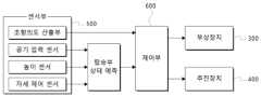
제어부(600)는 본 발명의 개인 이동 장치(1000)에 구비되는 모든 구성 장치에 대해서 제어할 수 있는 것으로, 외부로부터 신호를 송수신할 수 있으며, 내부의 구성장치와 신호를 송수신할 수 있는 것을 특징으로 한다. 도 6을 참고하면, 상기 제어부(600)는, 외부로부터 전달된 신호에 의해 부상장치(300) 및 추진장치(400)를 제어할 수 있으며, 상기 개인 이동 장치(1000)에 구비되는 복수의 센서가 측정한 값에 대해 수신하고, 이를 분석하여, 부상장치(300) 및 추진장치(400)를 제어하는 것으로, 장치(1000)의 이동 방향이나 속력, 높이 자세 및 에어스커트부(200)의 압력 등을 자유롭게 제어할 수 있는 것을 특징으로 한다. 상기 제어부(600)는 신호에 따라 기설정된 복수의 모드를 포함하고 있을 수 있으며, 모드에 의해, 일정 수준의 신호가 감지되면, 설정된 설정값에 따라 자동으로 동작이 수행되도록 구성될 수 있다. 상기 제어부(600)는 상기 부상장치(300) 및 추진장치(400)를 동시에 또는 각각 개별로 구분하여 제어할 수 있다.The
본 발명의 장치(1000)에 있어서, 제동이 필요한 경우에 각 장치들의 동작에 대해 일례를 들어 설명하면, 본 발명은 상기 에어스커트부(200)에 적어도 하나 이상의 밸브를 포함할 수 있으며, 상기 제어부(600)에 의해 상기 밸브와 상기 부상장치(300) 및 추진장치(400)가 복합적으로 작동하며 제동을 수행할 수 있다. 보다 상세히, 탑승자의 필요에 의해서나 또는 시스템 과부하와 같이 시스템이 정상적인 작동이 어렵다고 판단될 때, 상기 제어부(600)가 상기 제동 신호를 수신하면, 구비된 모든 상기 밸브를 오픈하고, 상기 추진장치(400)를 역방향으로 회전시킴으로써 상기 장치(1000)가 정지되도록 설정될 수 있다. 이때, 상기 제어부(600)는, 상기 장치(1000)가 소정 제1기준 속도 이하가 될 때 까지 상기 추진장치(400)의 출력이 역방향을 유지하도록 제어할 수 있다. 또한, 상기 장치(1000)가 상기 제1기준 속도 이하까지 상기 추진장치(400)의 출력이 역방향으로 회전하여, 소정의 제2기준 속도 이하가 되면, 상기 제어부(600)는, 상기 장치(1000)가 바닥면과의 접지력이 향상되도록 상기 부상장치(300)를 점진적으로 역방향으로 회전시켜, 상기 에어스커트부(200)의 내부가 음압이 되도록 제어할 수 있으며, 상기 제2기준 속도가 상기 제1기준속도에 비해서 같거나 작을 수 있다. 이때의 상기 부상장치(300)는 상기 제어부(600)에 의해 소정 시간 또는 안전 유지 지령에 기초하여 상기 부상장치(300)의 역방향 회전을 유지할 수 있다. 또한, 상기 센서부(500)로부터 수신한 정보에 기초하여 탑승자의 하차 의도를 판단하면, 안전 유지 지령을 활성화하여, 상기 제어부(600)에 의해 상기 부상장치(300) 및 추진장치(400)가 상기와 같이 작동하며, 상기 장치(1000)가 지면에 안전하게 부착되어서 정지할 수 있다. 더불어, 상기 제어부(600)는 상기 장치(1000)의 이동이 정지되기 이전의 상기 부상장치(300)의 역방향 출력인 제1출력에 비해서, 상기 장치(1000)가 정지된 후 상기 부상장치(300)의 역방향 출력인 제2출력이 작도록 제어를 수행할 수 있다. 이에, 상기 장치(1000)가 정지된 후, 상기 부상장치(300)는 상기 제2출력의 세기로 역방향 출력을 유지하되, 상기 장치(1000)에 탑승자의 하차나, 장치의 미끄러짐 등의 이동이 감지되면, 장치를 지면에 안전하게 고정하기 위해, 상기 제어부(600)가 상기 부상장치(300)의 출력을 상기 제2출력 보다 크게 제어하여, 상기 장치(1000)가 바닥면에 접지되는 접지력이 강해지며 보다 안정적으로 장치가 고정되도록 제어할 수 있다.In the
전원부(700)는 본 발명의 개인 이동 장치(1000)에 구비되는 모든 구동장치, 센서 및 제어장치에 전력을 공급 및 차단한다. 상기 전원부(700)는 배터리형태로 형성될 수 있으며, 배터리로 형성되는 경우, 배터리 관리 시스템을 통하여 충방전 및 적정 전력을 유지하도록 형성되는 것이 바람직하다.The
센서부(500)는 본 발명의 개인 이동 장치(1000)를 제어하기 위한 신호를 수신하는 것으로, 상기 개인 이동 장치(1000)의 높이, 자세, 위치, 속도, 압력 중 적어도 어느 하나 이상을 감지하여서 제어부(600)로 송신하는 것을 특징으로 한다. 상기 센서부(500)는 측정한 신호에 대해 제어부(600)로 송신하고, 상기 제어부(600)는, 수신한 신호를 기반으로 부상장치(300) 및 추진장치(400) 중 적어도 어느 하나 이상을 제어하는 것을 특징으로 한다. 일례로, 상기 센서부(500)로부터 수신한 신호에 따라, 상기 제어부(600)는 상기 추진장치(400)에 포함된 한 쌍의 제2팬(410) 중, 우측에 위치하는 상기 제2팬(410)의 속도를 좌측에 위치하는 상기 제2팬(410)의 속도보다 빠르게 제어함으로써, 개인 이동 장치(1000)가 좌회전의 동작을 수행하도록 제어될 수 있다.The
본 발명의 개인 이동 장치(1000)는 센서부(500)로, 조향의도 산출부를 더 포함할 수 있다. 도 6을 참고하면, 상기 조향의도 산출부는 상기 장치(1000)를 어느 방향으로 이동시키기 위해 제어하는 것으로, 탑승자가 상기 장치(1000)를 어느 방향으로 이동시키고자 하는 조향 의도에 대해 감지하여, 이를 제어부에 전달함으로써 장치(1000)의 진행방향을 제어하기 위한 것이다. 상기 조향의도 산출부는, 탑승자의 몸에 부착하거나 또는 탑승자가 소지할 수 있는 형태로 형성될 수 있으며, 탑승자의 조향 방향에 대해서 상기 제어부(600)와 신호를 송수신할 수 있는 것이면 제한 없이 사용될 수 있다. 이때, 조향 방향은 상기 개인 이동 장치(1000)의 좌회전 또는 우회전이나, 장치의 회전의 동작이나, 또는 전진 및 후진의 동작을 모두 포함할 수 있다. 또한, 상기 제어부(600)상기 조향의도 산출부로부터 신호를 수신하면, 신한 신호를 기반으로 부상장치(300) 및 추진장치(400) 중 적어도 어느 하나 이상을 제어할 수 있으며, 방향을 제어하는 경우, 상기 추진장치(400)의 한 쌍의 제2팬(410)을 제어하는 것이 바람직하다. 본 발명의 일례로, 상기 조향의도 산출부는 조이스틱, 헤드마운트 센서 및 근전도 센서 중 어느 하나 이상의 센서가 사용될 수 있다. 보다 상세히, 상기 조향의도 산출부가 조이스틱인 경우, 탑승자가 손에 조이스틱을 파지하여 상기 장치(1000)를 탑승하고, 운행 시 조이스틱을 상하좌우로 동작하는 것으로 상기 제어부(600)에 방향 전환 신호를 전달할 수 있다. 이후, 신호를 수신한 상기 제어부(600)가, 신호에 따라서 한 쌍의 상기 제2팬(410) 중 적어도 어느 하나 이상의 제2팬(410)에 대한 회전 속력 및 방향 중 적어도 어느 하나 이상을 제어하여서, 해당 방향으로 장치를 이동시키는 것을 특징으로 한다. 또한, 상기 조향의도 산출부가 근전도 센서인 경우, 탑승자의 몸에 근전도 센서를 부착하고, 근육의 움직임에 발생하는 신호를 상기 제어부(600)에 전달하도록 구성될 수 있다.The
본 발명의 개인 이동 장치(1000)는 센서부(500)로, 높이센서를 더 포함할 수 있다. 상기 높이센서는 상기 개인 이동 장치(1000)의 높이를 측정하는 것으로, 도 6을 참고하면, 측정한 높이를 제어부(600)에 전달하고, 상기 제어부(600)가 수신한 높이에 따라 추진장치(400)를 제어함으로써, 장치의 운용 높이를 제어하기 위한 것이다. 상기 높이센서는 구비되는 위치로부터 지면까지의 수직 높이를 측정하도록 설정되는 것이 바람직하며, 본 발명의 일례로, 높이에 따라 에어스커트부(200)의 내부 압력을 제어하기 위해서, 상기 높이센서는 에어스커트부(200)의 상면이 결합되는 탑승부(100)의 하면 부분에 위치되어, 지면까지의 높이를 측정하였을 때 에어스커트부(200)의 높이를 포함하는 높이를 측정하도록 형성될 수 있다. 이때, 상기 에어스커트부(200)의 높이는 공기 압력에 의해 부풀어지는 최대 높이에 대해 한계값을 가지고 있으므로, 상기 제어부(600)는 상기 에어스커트부(200)의 최대 높이를 고려하여 장치(1000)가 지면에 부상한 높이를 계산하도록 설정되는 것이 바람직하다. 본 발명은 상기 높이센서가 측정한 높이를 통해 탑승부 상태 예측을 수행할 수 있고, 상기 탑승부 상태 예측을 기초로 상기 제어부(600)가 상기 장치를 제어하는 것을 특징으로 한다, 보다 상세히, 상기 제어부(600)는 본 장치가 지면으로부터 일정 높이를 유지하면서 부상하여 이동하도록 제어될 수 있으며, 이에 상기 높이센서가 실시간으로 지면과의 높이를 측정하고, 이를 제어부(600)가 수신하며, 수신된 높이에 따라서 상기 추진장치(400)를 제어하는 것으로 부상력을 조절하도록 구성될 수 있다. 일례로, 지면에 형성된 장애물에 의해 상기 높이센서가 측정한 높이에 대해, 제어부(600)에서 일정 이하의 높이 값을 인지하는 경우, 상기 제어부(600)는 수신한 높이 값에 따라서, 보강하여 부상해야하는 부상력을 계산하고, 이에 대해 상기 추진장치(400)의 제1팬(310)의 회전 속력을 증가시키는 것으로, 부상력을 보강함으로써 본 장치(1000)가 보다 높게 부상되도록 제어할 수 있다. 상기 높이센서는 복수개로 형성되어 장치에 구비될 수 있으며, 복수의 상기 높이센서는, 상기 개인 이동 장치(1000)의 전방, 후방, 좌측 및 우측 중 적어도 어느 하나 이상의 위치에 배치될 수 있다. 이때, 일례로, 상기 높이센서가 개인 이동 장치(1000)의 전방에 하나가 배치되는 경우, 장치의 전방 폭을 기준으로 중심의 위치에 배치되는 것이 바람직하다. 또한, 상기 높이센서가 4개로 형성되어 전후좌우측에 각각 배치되는 경우, 각 장치의 폭을 기준으로 중심이 되는 위치에 각각 배치되는 것이 바람직하다. 상기 제어부(600)는 필요에 따라서, 일정 시간 간격으로 상기 높이센서가 값을 측정하여 전달하도록 설정하거나, 또는 상기 높이센서가 일정 기준의 높이 값 이외로 변동된 값을 인지하면 상기 제어부(600)에 전달하도록 설정될 수 있다.The
본 발명의 개인 이동 장치(1000)는 센서부(500)로, 공기압력센서를 더 포함할 수 있다. 도 6을 참고하면, 상기 공기압력센서는 에어스커트부(200) 내부의 압력을 측정하고, 제어하기 위한 것으로, 상기 공기압력센서는 측정된 압력을 제어부(600)에 전달할 수 있다. 상기 공기압력센서는 공기가 유입되며 부푸는 상기 에어스커트부(200)의 높이를 조절하기 위한 것으로, 또한, 상기 에어스커트부(200)의 부상력을 제어할 수 있다. 상기 공기압력센서는 탑승자의 무게에 따라서 상기 에어스커트부(200) 내부의 압력을 조절하거나, 또는 지면의 장애물에 의해서 부상력을 조절하는 등 탑승자의 필요에 따라서 제어될 수 있도록 선택적으로 사용할 수 있다. 예를 들어, 본 장치(1000)는 탑승자의 무게에 대해 인지할 수 있으며, 상기 제어부(600)는 상기 공기압력센서를 이용하여 탑승자의 무게가 무거운 경우, 상기 부상장치(300)가 형성하는 공기 압력이 보다 높게 발생되어서 상기 에어스커트부(200) 내부의 압력이 높아질 수 있도록 상기 추진장치(400)를 제어할 수 있다. 본 발명은 상기 공기압력센서가 측정한 상기 에어스커트부(200) 내부의 압력을 통해 탑승부 상태 예측을 수행할 수 있고, 상기 탑승부 상태 예측을 기초로 상기 제어부(600)가 상기 장치를 제어하는 것을 특징으로 한다, 보다 상세히, 상기 제어부(600)는 상기 공기압력센서로부터 신호를 수신하면, 공기 압력의 세기에 따라 상기 부상장치(300)를 제어함으로써 상기 에어스커트부(200)의 내부 압력을 조정하는 것으로 본 장치(1000)의 부상력을 제어하도록 구성될 수 있다. 또한, 본 발명은 상기 개인 이동 장치(1000)가 일정 수준의 공기압을 유지하기 위해서, 일정 간격으로 상기 공기압력센서로부터 신호를 수신하도록 설정될 수 있으며, 신호에 따라서 상기 제어부(600)가 상기 부상장치(300)를 제어하도록 설정될 수 있다. 더불어, 상기 제어부(600)는 탑승자의 필요에 따라 부상력을 제어하고 싶은 상황에 대해서 기준을 기설정하고, 상기 기준에 벗어나는 경우 상기 공기압력센서가 에어스커트부(200)의 공기압력을 측정하여 상기 제어부(600)에 송신하도록 설정될 수 있다. 상기 공기압력센서는 상기 에어스커트부(200) 내부에 구비되어 공기 압력을 측정할 수 있지만, 이런 경우 탄성이 있는 재질로 형성되는 에어스커트부(200)가, 상기 공기압력센서에 의해 표면에 굴곡이 형성되고, 굴곡에 의해 상기 에어스커트부(200) 장치가 긁히거나 찢어지는 등의 손상이 발생될 수 있다. 따라서, 상기 공기압력센서는, 상기 에어스커트부(200)로 공기를 유입시키는 상기 부상장치(300)의 모터 출구에 구비되는 것이 바람직하다.The
본 발명의 개인 이동 장치(1000)는 센서부(500)로, 자세제어센서를 더 포함할 수 있다. 상기 자세제어센서는 관성을 이용하여 장치(1000)의 자세를 측정하는 IMU 및, 장치(1000)의 위치 및 속도를 측정하는 GPS 중 적어도 어느 하나 이상의 센서를 포함하는 것을 특징으로 한다. 상기 자세제어센서는 탑승과 균형을 잡는데 안정감을 향상시키기 위한 것으로, 도 6을 참고하면, 본 발명은 상기 자세제어센서가 측정한 탑승부의 기울어짐 정도를 통해 탑승부 상태 예측을 수행할 수 있고, 상기 탑승부 상태 예측을 통해 상기 제어부(600)가 상기 장치를 제어하는 것을 특징으로 한다, 보다 상세히, 상기 자세제어센서는 상기 IMU 및 GPS 등으로 측정한 측정값에 대해 제어부(600)에 송신하고, 상기 제어부(600)는 수신한 측정값을 통해 탑승부의 기울기나 회전 자세 등을 예측할 수 있고, 예측한 기울기에 따라서 장치(1000)의 자세를 제어하는 것을 특징으로 한다. 상기 자세제어센서는 IMU를 통해 본 장치(1000)의 회전 자세를 감지할 수 있고, GPS통해 장치(1000)의 전후 및 좌우의 속도를 감지하여 자세를 확인할 수 있으며, 이를 기반으로, 상기 제어부(600)가 사람의 움직임과 장치(1000)의 회전 등을 고려하여 장치(1000)가 제자리 자세를 유지 및 변경하는데 활용하도록 설정될 수 있다. 일례로, 본 발명의 상기 개인 이동 장치(1000)는 부상력에 의해 장치가 지면으로부터 소정 높이 부양된 상태로 운용이 되는데, 이에 사람이 탑승할 때 미끄러지거나 장치가 흔들리며 탑승에 어려움이 생긴다. 이에, 상기 자세제어센서가 실시간으로 장치(1000)의 자세를 측정하고, 이에 상기 제어부(600)가 수신된 값을 통해 상기 장치(1000)가 정자세를 유지할 수 있도록 실시간으로 상기 부상장치(300) 및 추진장치(400) 중 적어도 어느 하나 이상의 팬을 제어하여 장치(1000)의 자세가 일정하게 유지되도록 제어할 수 있다. 상기 자세제어센서를 통해 장치(1000)가 운용하고자 하는 주행 방향 이외에 과하게 흔들리거나 회전하는 동작을 방지함으로써, 탑승자가 보다 안전하고 안정적으로 장치를 탑승하고, 주행할 수 있는 것을 특징으로 한다.The
이상과 같이 본 발명에서는 구체적인 구성 소자 등과 같은 특정 사항들과 한정된 실시예 도면에 의해 설명되었으나 이는 본 발명의 보다 전반적인 이해를 돕기 위해서 제공된 것 일 뿐, 본 발명은 상기의 일 실시예에 한정되는 것이 아니며, 본 발명이 속하는 분야에서 통상의 지식을 가진 자라면 이러한 기재로부터 다양한 수정 및 변형이 가능하다.As described above, the present invention has been described with reference to specific details such as specific components and drawings of limited embodiments, but this is only provided to facilitate a more general understanding of the present invention, and the present invention is not limited to the above-mentioned embodiment. No, those skilled in the art can make various modifications and variations from this description.
따라서, 본 발명의 사상은 설명된 실시예에 국한되어 정해져서는 아니 되며, 후술하는 특허 청구 범위뿐 아니라 이 특허 청구 범위와 균등하거나 등가적 변형이 있는 모든 것들은 본 발명 사상의 범주에 속한다고 할 것이다.Accordingly, the spirit of the present invention should not be limited to the described embodiments, and all matters that are equivalent or equivalent to the claims of this patent as well as the claims described below shall fall within the scope of the spirit of the present invention. .
1000 : 공기 부상식 개인 이동 장치
100 : 탑승부110 : 먼지거름망
120 : 유로
200 : 에어스커트부210 : 주구멍
220 : 패드
300 : 부상장치310 : 제1팬
320 : 덕트330 : 모터
400 : 추진장치410 : 제2팬
500 : 센서부
600 : 제어부
700 : 전원부1000 : Air hovering personal mobility device
100: Boarding section 110: Dust filter
120: Euro
200: Air skirt part 210: Main hole
220: pad
300: Levitation device 310: First fan
320: duct 330: motor
400: Propulsion device 410: Second fan
500: sensor unit
600: Control unit
700: Power unit
Claims (18)
Translated fromKorean내부에 소정 공간을 포함하고, 상판이 평평하게 형성되어, 탑승자가 상기 상판에 탑승하는 탑승부;
상기 탑승부의 하면에 결합되며, 하면에 적어도 하나 이상의 공기구멍이 형성되는 에어스커트부;
상기 공간에 수용되는 적어도 하나 이상의 제1팬을 포함하고, 상기 제1팬에 의해 상기 에어스커트부에 공기를 제공하는 부상장치;
상기 공간에 수용되며 상기 탑승부의 길이방향 중 어느 일측에 구비되되, 좌우 대칭되게 각각 배치되는 한 쌍의 제2팬을 포함하는 추진장치; 및
상기 부상장치 및 상기 추진장치를 제어하는 제어부;를 포함하고,
상기 제어부는,
상기 공기 부상식 개인 이동 장치의 제동이 필요한 경우,
상기 부상장치의 출력을 역방향으로 제어하여, 상기 에어스커트부 내부의 공기를 외부로 배출하며 음압으로 형성시켜 상기 공기 부상식 개인 이동 장치와 바닥면간 접지력이 점진적으로 높아지게 제어하여 제동하는 것을 특징으로 하는 공기 부상식 개인 이동 장치.
In the air-floating personal mobility device,
A boarding unit that includes a predetermined space inside and has a flat upper plate, so that the passenger rides on the upper plate;
An air skirt part coupled to the lower surface of the boarding unit and having at least one air hole formed in the lower surface;
a flotation device including at least one first fan accommodated in the space and providing air to the air skirt portion by the first fan;
a propulsion device accommodated in the space and provided on one side of the longitudinal direction of the boarding unit, including a pair of second fans arranged symmetrically on the left and right; and
It includes a control unit that controls the flotation device and the propulsion device,
The control unit,
If braking of said airborne personal mobility device is required,
By controlling the output of the flotation device in the reverse direction, the air inside the air skirt is discharged to the outside and formed into negative pressure, so that the grounding force between the air floating personal mobility device and the floor is gradually increased and controlled for braking. Inflatable personal mobility device.
상기 공기 부상식 개인 이동 장치는,
높이, 자세, 위치, 속도, 압력 중 적어도 어느 하나 이상을 감지하여 상기 제어부에 송신하는 센서부;를 더 포함하고,
상기 제어부는, 상기 센서부로부터 수신된 적어도 하나 이상의 정보에 따라서, 상기 부상장치 및 추진장치 중 적어도 어느 하나 이상을 제어하는 것
을 특징으로 하는 공기 부상식 개인 이동 장치.
According to clause 1,
The air-floating personal mobility device,
It further includes a sensor unit that detects at least one of height, posture, position, speed, and pressure and transmits it to the control unit,
The control unit controls at least one of the flotation device and the propulsion device according to at least one information received from the sensor unit.
An air-floating personal mobility device featuring:
상기 제어부는,
한 쌍의 상기 제2팬을 서로 다른 속도 및 방향으로 회전시키는 것을 특징으로 하는 공기 부상식 개인 이동 장치.
According to clause 2,
The control unit,
An air-floating personal mobility device, characterized in that the pair of second fans rotates at different speeds and directions.
상기 센서부는,
장치의 동작에 의해 탑승자의 조향 의도를 감지하여 상기 제어부로 송신하는 조향의도 산출부를 더 포함하고,
상기 제어부는,
상기 조향의도 산출부로부터 수신한 신호에 따라, 상기 추진장치 및 상기 부상장치 중 적어도 하나를 제어하는 것을 특징으로 하는 공기 부상식 개인 이동 장치.
According to clause 2,
The sensor unit,
It further includes a steering intention calculation unit that detects the steering intention of the occupant through the operation of the device and transmits it to the control unit,
The control unit,
An air floating personal mobility device, characterized in that controlling at least one of the propulsion device and the flotation device according to a signal received from the steering intention calculation unit.
상기 조향의도 산출부는,
조이스틱, 헤드마운트 센서 및 근전도 센서 중 적어도 어느 하나 이상인 것
을 특징으로 하는 공기 부상식 개인 이동 장치.
According to clause 4,
The steering intention calculation unit,
At least one of a joystick, head-mounted sensor, and electromyography sensor
An air-floating personal mobility device featuring:
상기 센서부는,
상기 에어스커트부의 내부에 구비되어, 상기 에어스커트부 내부의 압력을 측정하고, 측정된 압력을 상기 제어부로 송신하는 공기압력센서를 더 포함하고,
상기 제어부는,
상기 공기압력센서로부터 수신한 압력 세기에 기초하여, 상기 부상장치를 제어하는 것을 특징으로 하는 공기 부상식 개인 이동 장치.
According to clause 2,
The sensor unit,
It further includes an air pressure sensor provided inside the air skirt unit, measuring the pressure inside the air skirt unit, and transmitting the measured pressure to the control unit,
The control unit,
An air floating personal mobility device, characterized in that controlling the levitation device based on the pressure intensity received from the air pressure sensor.
상기 센서부는,
바닥면으로부터 상기 공기 부상식 개인 이동 장치의 적어도 일부까지의 높이를 측정하는 높이센서를 더 포함하고,
상기 제어부는, 상기 높이센서로부터 수신한 높이에 기초하여, 상기 부상장치 및 상기 추진장치 중 적어도 하나를 제어하는 것을 특징으로 하는 공기 부상식 개인 이동 장치.
According to clause 2,
The sensor unit,
Further comprising a height sensor that measures the height from the floor to at least a portion of the air floating personal mobility device,
The control unit, based on the height received from the height sensor, controls at least one of the flotation device and the propulsion device.
상기 높이센서는, 복수개로 형성될 수 있고,
상기 공기 부상식 개인 이동 장치의 전, 후, 좌 및 우측 중 적어도 하나 이상의 위치에 배치되는 것을 특징으로 하는 공기 부상식 개인 이동 장치.
According to clause 7,
The height sensor may be formed in plural numbers,
An air-floating personal mobility device, characterized in that it is disposed at least one of front, rear, left, and right positions of the air-floating personal mobility device.
상기 센서부는,
상기 탑승부에 구비되어, 상기 탑승부의 회전 자세와 위치 및 속도를 측정하여 상기 제어부로 송신하는 IMU 및 GPS 중 적어도 하나 이상의 자세제어센서를 더 포함하고,
상기 제어부는, 상기 자세제어센서로부터 수신한 정보에 따라서, 상기 부상장치 및 추진장치 중 적어도 어느 하나 이상을 제어하는 것을 특징으로 하는 공기 부상식 개인 이동 장치.
According to clause 2,
The sensor unit,
It further includes at least one attitude control sensor selected from IMU and GPS, which is provided on the boarding unit and measures the rotational attitude, position, and speed of the boarding unit and transmits them to the control unit,
The control unit is an air floating personal mobility device, characterized in that it controls at least one of the flotation device and the propulsion device according to the information received from the posture control sensor.
상기 에어스커트부는, 상기 에어스커트부의 내부 공기를 외부로 배출하는 적어도 하나 이상의 밸브를 포함하는 것을 특징으로 하는 공기 부상식 개인 이동 장치.
According to clause 1,
The air skirt unit is an air floating personal mobility device, characterized in that it includes at least one valve that discharges the air inside the air skirt unit to the outside.
상기 제어부는,
상기 공기 부상식 개인 이동 장치의 제동이 필요한 경우,
상기 공기 부상식 개인 이동 장치의 진행 방향으로의 속도가 소정 제 1 기준 속도 이하가 될 때까지 상기 추진장치의 출력을 역방향으로 제어하여 상기 공기 부상식 개인 이동 장치의 이동을 정지시키는 것을 특징으로 하는 공기 부상식 개인 이동 장치.
According to clause 1,
The control unit,
If braking of said airborne personal mobility device is required,
Characterized in that stopping the movement of the air-floating personal mobility device by controlling the output of the propulsion device in the reverse direction until the speed in the direction of travel of the air-floating personal mobility device becomes less than or equal to a predetermined first reference speed. Inflatable personal mobility device.
상기 제어부는,
상기 공기 부상식 개인 이동 장치의 제동이 필요한 경우,
상기 추진장치는, 상기 공기 부상식 개인 이동 장치의 진행 방향으로의 속도가 소정의 제 1 기준 속도 이하가 될 때까지 역방향으로 회전시키되,
상기 공기 부상식 개인 이동 장치의 진행 방향으로의 속도가 소정의 제 2 기준 속도 이하가 되면,
상기 부상장치를 점진적으로 역방향으로 제어하여, 상기 에어스커트부 내부의 공기를 외부로 배출하며 음압으로 형성시켜, 상기 공기 부상식 개인 이동 장치와 바닥면간 접지력이 점진적으로 높아지게 제어하여 제동하고,
이때, 상기 제 2 기준 속도가 상기 제 1 기준 속도에 비해서 같거나 작은 것을 특징으로 하는 공기 부상식 개인 이동 장치.
According to clause 1,
The control unit,
If braking of said airborne personal mobility device is required,
The propulsion device rotates in the reverse direction until the speed in the direction of travel of the air-floating personal mobility device becomes less than or equal to a predetermined first reference speed,
When the speed in the direction of travel of the air-floating personal mobility device becomes less than or equal to a predetermined second reference speed,
By gradually controlling the levitation device in the reverse direction, the air inside the air skirt is discharged to the outside and formed into negative pressure, so that the grounding force between the air floating personal mobility device and the floor is gradually increased and braked,
At this time, an air floating personal mobility device, characterized in that the second reference speed is equal to or smaller than the first reference speed.
내부에 소정 공간을 포함하고, 상판이 평평하게 형성되어, 탑승자가 상기 상판에 탑승하는 탑승부;
상기 탑승부의 하면에 결합되며, 하면에 적어도 하나 이상의 공기구멍이 형성되는 에어스커트부;
상기 공간에 수용되는 적어도 하나 이상의 제1팬을 포함하고, 상기 제1팬에 의해 상기 에어스커트부에 공기를 제공하는 부상장치;
상기 공간에 수용되며 상기 탑승부의 길이방향 중 어느 일측에 구비되되, 좌우 대칭되게 각각 배치되는 한 쌍의 제2팬을 포함하는 추진장치; 및
상기 부상장치 및 상기 추진장치를 제어하는 제어부;를 포함하고,
상기 제어부는,
상기 공기 부상식 개인 이동 장치의 제동이 필요한 경우,
상기 추진장치는, 상기 공기 부상식 개인 이동 장치의 진행 방향으로의 속도가 소정의 제 1 기준 속도 이하가 될 때까지 역방향으로 회전시키되,
상기 공기 부상식 개인 이동 장치의 진행 방향으로의 속도가 소정의 제 2 기준 속도 이하가 되면,
상기 부상장치를 점진적으로 역방향으로 제어하여, 상기 에어스커트부 내부의 공기를 외부로 배출하며 음압으로 형성시켜, 상기 공기 부상식 개인 이동 장치와 바닥면간 접지력이 점진적으로 높아지게 제어하여 제동하고,
이때, 상기 제 2 기준 속도가 상기 제 1 기준 속도에 비해서 같거나 작은 것을 특징으로 하며,
상기 공기 부상식 개인 이동 장치의 이동을 정지된 이후에도, 소정 시간 또는 안전 유지 지령에 기초하여 상기 공기 부상식 개인 이동 장치와 바닥면간 접지력이 유지되도록 상기 부상장치를 역방향으로 회전시키는 것을 유지하는 것을 특징으로 하는 공기 부상식 개인 이동 장치.
In the air-floating personal mobility device,
A boarding unit that includes a predetermined space inside and has a flat upper plate, so that the passenger rides on the upper plate;
An air skirt part coupled to the lower surface of the boarding unit and having at least one air hole formed in the lower surface;
a flotation device including at least one first fan accommodated in the space and providing air to the air skirt portion by the first fan;
a propulsion device accommodated in the space and provided on one side of the longitudinal direction of the boarding unit, including a pair of second fans arranged symmetrically on the left and right; and
It includes a control unit that controls the flotation device and the propulsion device,
The control unit,
If braking of said airborne personal mobility device is required,
The propulsion device rotates in the reverse direction until the speed in the direction of travel of the air-floating personal mobility device becomes less than or equal to a predetermined first reference speed,
When the speed in the direction of travel of the air-floating personal mobility device becomes less than or equal to a predetermined second reference speed,
By gradually controlling the levitation device in the reverse direction, the air inside the air skirt is discharged to the outside and formed into negative pressure, so that the grounding force between the air floating personal mobility device and the floor is gradually increased and braked,
At this time, the second reference speed is equal to or smaller than the first reference speed,
Even after the movement of the air-floating personal mobility device is stopped, the flotation device is maintained to rotate in the reverse direction so that the grounding force between the air-floating personal mobility device and the floor is maintained based on a predetermined time or safety maintenance command. An air-floating personal mobility device.
상기 제어부는,
상기 공기 부상식 개인 이동 장치에 구비되어 높이, 자세, 위치, 속도, 압력 중 적어도 어느 하나 이상을 감지하여 상기 제어부에 송신하는 센서부로부터 수신한 정보에 기초하여 상기 탑승자 중 적어도 일부의 하차 의도를 판단하고,
상기 탑승자 중 적어도 일부의 하차 의도가 있다고 판단되는 경우, 상기 안전 유지 지령을 활성화하는 것을 특징으로 하는 공기 부상식 개인 이동 장치.
According to clause 14,
The control unit,
The intention to disembark of at least some of the passengers is determined based on information received from a sensor unit provided in the air-floating personal mobility device that detects at least one of height, posture, position, speed, and pressure and transmits the information to the control unit. judge,
An airborne personal mobility device, characterized in that activating the safety maintenance command when it is determined that at least some of the occupants intend to disembark.
상기 제어부는,
상기 공기 부상식 개인 이동 장치의 이동이 정지되기 이전 상기 부상장치의 역방향 출력인 제 1 출력에 비해서, 상기 공기 부상식 개인 이동 장치가 정지된 후 상기 부상장치의 역방향 출력인 제 2 출력이 작은 것을 특징으로 하는 공기 부상식 개인 이동 장치.
According to clause 14,
The control unit,
Compared to the first output, which is the reverse output of the flotation device before the movement of the air-floating personal mobility device is stopped, the second output, which is the reverse output of the flotation device after the air-floating personal mobility device is stopped, is smaller. Features an air-floating personal mobility device.
상기 제어부는,
상기 공기 부상식 개인 이동 장치가 정지된 후 상기 부상장치를 역방향 출력인 제 2 출력으로 유지하되,
상기 공기 부상식 개인 이동 장치의 이동이 감지되면, 상기 공기 부상식 개인 이동 장치의 이동을 제한하기 위해 상기 부상장치의 역방향 출력을 상기 제 2 출력보다 크게 제어하는 것을 특징으로 하는 공기 부상식 개인 이동 장치.
According to clause 16,
The control unit,
After the air-floating personal mobility device is stopped, the flotation device is maintained at a second output, which is a reverse output,
When movement of the air-floating personal mobility device is detected, the reverse output of the flotation device is controlled to be greater than the second output to limit the movement of the air-floating personal mobility device. Device.
상기 에어스커트부는,
유입되는 공기의 양에 따라 부피 조절이 가능한 탄성 재질을 포함하는 제1영역; 및
상기 탄성 재질보다 단단한 재질의 패드를 포함하는 제2영역;을 포함하는 것을 특징으로 하는 공기 부상식 개인 이동 장치.According to claim 1 or 14,
The air skirt part,
A first region including an elastic material whose volume can be adjusted according to the amount of incoming air; and
A second region comprising a pad made of a harder material than the elastic material.
Priority Applications (1)
| Application Number | Priority Date | Filing Date | Title |
|---|---|---|---|
| KR1020220011556AKR102653855B1 (en) | 2022-01-26 | 2022-01-26 | Air Floating Personal Mobility Device |
Applications Claiming Priority (1)
| Application Number | Priority Date | Filing Date | Title |
|---|---|---|---|
| KR1020220011556AKR102653855B1 (en) | 2022-01-26 | 2022-01-26 | Air Floating Personal Mobility Device |
Publications (2)
| Publication Number | Publication Date |
|---|---|
| KR20230115383A KR20230115383A (en) | 2023-08-03 |
| KR102653855B1true KR102653855B1 (en) | 2024-04-03 |
Family
ID=87568005
Family Applications (1)
| Application Number | Title | Priority Date | Filing Date |
|---|---|---|---|
| KR1020220011556AActiveKR102653855B1 (en) | 2022-01-26 | 2022-01-26 | Air Floating Personal Mobility Device |
Country Status (1)
| Country | Link |
|---|---|
| KR (1) | KR102653855B1 (en) |
Citations (11)
| Publication number | Priority date | Publication date | Assignee | Title |
|---|---|---|---|---|
| JP4155081B2 (en) | 2003-04-02 | 2008-09-24 | トヨタ自動車株式会社 | Vertical take-off and landing equipment |
| WO2013041786A1 (en) | 2011-09-19 | 2013-03-28 | Personal Water Craft Product | Passenger propulsion device and system |
| US20130306803A1 (en)* | 2009-07-03 | 2013-11-21 | Xiaoyi Zhu | Aircraft generating a lift from an interior thereof |
| WO2014151980A1 (en) | 2013-03-15 | 2014-09-25 | Jlip, Llc | Personal propulsion devices with improved balance |
| WO2015103700A1 (en) | 2014-01-07 | 2015-07-16 | 4525612 Canada Inc. Dba Maginaire | Personal flight vehicle |
| WO2017009695A1 (en) | 2015-07-11 | 2017-01-19 | Sadhana Dhiraj Panchal Sanjay | Multi-utility multi-object transformable portable mobility apparatus |
| US20170300051A1 (en) | 2013-02-06 | 2017-10-19 | Dylan T X Zhou | Amphibious vertical take off and landing unmanned device with AI data processing apparatus |
| WO2018083354A1 (en)* | 2016-11-07 | 2018-05-11 | Ziph20 | Propulsion system and device for a passenger |
| US20180208312A1 (en) | 2016-11-07 | 2018-07-26 | ZipAir SAS | Systems and methods for improved flight control |
| WO2018135896A1 (en) | 2017-01-19 | 2018-07-26 | 차영천 | Traction device using drone |
| WO2019198768A1 (en) | 2018-04-10 | 2019-10-17 | 株式会社自律制御システム研究所 | Unmanned aerial vehicle |
Family Cites Families (4)
| Publication number | Priority date | Publication date | Assignee | Title |
|---|---|---|---|---|
| KR20150122879A (en)* | 2014-04-23 | 2015-11-03 | (주)엠텍 | Riding robot having steering saddle |
| KR101765074B1 (en)* | 2016-01-12 | 2017-08-07 | 아주대학교산학협력단 | Unmanned aerial vehicle for evacuating people from skyscraper and managing method for the same |
| KR20200088656A (en)* | 2019-01-15 | 2020-07-23 | 한국항공우주연구원 | Personal flight apparatus |
| KR20210018367A (en)* | 2021-01-26 | 2021-02-17 | 김용원 | The auto aircraft propullor and drone propulsor are installed as options electric(Generator) motorcycle motor |
- 2022
- 2022-01-26KRKR1020220011556Apatent/KR102653855B1/enactiveActive
Patent Citations (11)
| Publication number | Priority date | Publication date | Assignee | Title |
|---|---|---|---|---|
| JP4155081B2 (en) | 2003-04-02 | 2008-09-24 | トヨタ自動車株式会社 | Vertical take-off and landing equipment |
| US20130306803A1 (en)* | 2009-07-03 | 2013-11-21 | Xiaoyi Zhu | Aircraft generating a lift from an interior thereof |
| WO2013041786A1 (en) | 2011-09-19 | 2013-03-28 | Personal Water Craft Product | Passenger propulsion device and system |
| US20170300051A1 (en) | 2013-02-06 | 2017-10-19 | Dylan T X Zhou | Amphibious vertical take off and landing unmanned device with AI data processing apparatus |
| WO2014151980A1 (en) | 2013-03-15 | 2014-09-25 | Jlip, Llc | Personal propulsion devices with improved balance |
| WO2015103700A1 (en) | 2014-01-07 | 2015-07-16 | 4525612 Canada Inc. Dba Maginaire | Personal flight vehicle |
| WO2017009695A1 (en) | 2015-07-11 | 2017-01-19 | Sadhana Dhiraj Panchal Sanjay | Multi-utility multi-object transformable portable mobility apparatus |
| WO2018083354A1 (en)* | 2016-11-07 | 2018-05-11 | Ziph20 | Propulsion system and device for a passenger |
| US20180208312A1 (en) | 2016-11-07 | 2018-07-26 | ZipAir SAS | Systems and methods for improved flight control |
| WO2018135896A1 (en) | 2017-01-19 | 2018-07-26 | 차영천 | Traction device using drone |
| WO2019198768A1 (en) | 2018-04-10 | 2019-10-17 | 株式会社自律制御システム研究所 | Unmanned aerial vehicle |
Also Published As
| Publication number | Publication date |
|---|---|
| KR20230115383A (en) | 2023-08-03 |
Similar Documents
| Publication | Publication Date | Title |
|---|---|---|
| JP5524970B2 (en) | Aircraft system capable of running on the ground | |
| KR100719032B1 (en) | Transportation system | |
| EP2355764B1 (en) | Transportation apparatus and method for carrying a payload in a desired plane independent of 3d tilting of said apparatus | |
| JP2002087255A (en) | Person carrier | |
| US6315674B1 (en) | Amusement ride for vertical movement of passengers | |
| US6719079B2 (en) | Ground effect vehicle using a frontal ram air stream and aerodynamic lift | |
| KR101524194B1 (en) | Hydrofoil boat | |
| KR102653855B1 (en) | Air Floating Personal Mobility Device | |
| US6230835B1 (en) | Ground effect vehicle | |
| US20110308422A1 (en) | Propulsion vehicle which travels along a soft, porous track | |
| US4175637A (en) | Surface effect vehicles and guideways therefor | |
| JP2001354199A (en) | Method and device for taking off/landing of unmanned aircraft | |
| JP6436571B2 (en) | Aircraft and high-speed traffic systems | |
| KR102653867B1 (en) | Floating device | |
| JPS592964A (en) | Air car | |
| KR102707208B1 (en) | Floating mobile device for personal mobility | |
| JP2004026034A (en) | Vertical takeoff and landing aircraft | |
| CN102555710A (en) | Multifunctional flying fish used in water, land and sky | |
| US20060208133A1 (en) | Personal aircraft vehicle | |
| EP3448539B1 (en) | Underwater park ride system | |
| JP2022028578A (en) | Flight vehicle | |
| JP2021049960A (en) | Flight body | |
| CN202557241U (en) | Multifunctional vehicle used in water, land and air | |
| Dave et al. | Working model of remote controlled hovercraft | |
| JP2000344194A (en) | Aerial floating device |
Legal Events
| Date | Code | Title | Description |
|---|---|---|---|
| PA0109 | Patent application | Patent event code:PA01091R01D Comment text:Patent Application Patent event date:20220126 | |
| PA0201 | Request for examination | ||
| PG1501 | Laying open of application | ||
| E902 | Notification of reason for refusal | ||
| PE0902 | Notice of grounds for rejection | Comment text:Notification of reason for refusal Patent event date:20230820 Patent event code:PE09021S01D | |
| E90F | Notification of reason for final refusal | ||
| PE0902 | Notice of grounds for rejection | Comment text:Final Notice of Reason for Refusal Patent event date:20240129 Patent event code:PE09021S02D | |
| E701 | Decision to grant or registration of patent right | ||
| PE0701 | Decision of registration | Patent event code:PE07011S01D Comment text:Decision to Grant Registration Patent event date:20240320 | |
| GRNT | Written decision to grant | ||
| PR0701 | Registration of establishment | Comment text:Registration of Establishment Patent event date:20240328 Patent event code:PR07011E01D | |
| PR1002 | Payment of registration fee | Payment date:20240329 End annual number:3 Start annual number:1 | |
| PG1601 | Publication of registration |