KR102653403B1 - Flexible piping management systems for pharmaceutical, bioprocess applications, and food/dairy applications - Google Patents
Flexible piping management systems for pharmaceutical, bioprocess applications, and food/dairy applicationsDownload PDFInfo
- Publication number
- KR102653403B1 KR102653403B1KR1020187010190AKR20187010190AKR102653403B1KR 102653403 B1KR102653403 B1KR 102653403B1KR 1020187010190 AKR1020187010190 AKR 1020187010190AKR 20187010190 AKR20187010190 AKR 20187010190AKR 102653403 B1KR102653403 B1KR 102653403B1
- Authority
- KR
- South Korea
- Prior art keywords
- conduit
- track
- channel
- flexible
- connector
- Prior art date
- Legal status (The legal status is an assumption and is not a legal conclusion. Google has not performed a legal analysis and makes no representation as to the accuracy of the status listed.)
- Active
Links
- 235000013305foodNutrition0.000titleclaimsabstractdescription14
- 235000013365dairy productNutrition0.000titleabstractdescription10
- 238000000034methodMethods0.000claimsabstractdescription28
- 229920000642polymerPolymers0.000claimsdescription7
- 229920001296polysiloxanePolymers0.000claimsdescription6
- 238000010828elutionMethods0.000claimsdescription4
- 238000004587chromatography analysisMethods0.000claimsdescription3
- 230000008569processEffects0.000abstractdescription23
- 238000004519manufacturing processMethods0.000description11
- 239000012530fluidSubstances0.000description7
- 229960000074biopharmaceuticalDrugs0.000description6
- 239000003814drugSubstances0.000description6
- 230000014759maintenance of locationEffects0.000description5
- 229940079593drugDrugs0.000description4
- 239000000463materialSubstances0.000description4
- 229920002725thermoplastic elastomerPolymers0.000description4
- 238000010276constructionMethods0.000description3
- 238000013461designMethods0.000description3
- 239000004033plasticSubstances0.000description3
- 238000011112process operationMethods0.000description3
- 239000000047productSubstances0.000description3
- 239000000126substanceSubstances0.000description3
- 238000004140cleaningMethods0.000description2
- 238000005520cutting processMethods0.000description2
- 239000012467final productSubstances0.000description2
- 239000000203mixtureSubstances0.000description2
- 230000000717retained effectEffects0.000description2
- 238000004659sterilization and disinfectionMethods0.000description2
- 230000010757Reduction ActivityEffects0.000description1
- 239000000853adhesiveSubstances0.000description1
- 230000001070adhesive effectEffects0.000description1
- 238000013459approachMethods0.000description1
- 230000031018biological processes and functionsEffects0.000description1
- 239000012459cleaning agentSubstances0.000description1
- 150000001875compoundsChemical class0.000description1
- 230000006835compressionEffects0.000description1
- 238000007906compressionMethods0.000description1
- 238000012864cross contaminationMethods0.000description1
- 238000010586diagramMethods0.000description1
- 238000000855fermentationMethods0.000description1
- 230000004151fermentationEffects0.000description1
- 238000001914filtrationMethods0.000description1
- 238000003780insertionMethods0.000description1
- 230000037431insertionEffects0.000description1
- 239000007788liquidSubstances0.000description1
- 238000012423maintenanceMethods0.000description1
- 230000007246mechanismEffects0.000description1
- 239000002184metalSubstances0.000description1
- 239000007769metal materialSubstances0.000description1
- 238000012986modificationMethods0.000description1
- 230000004048modificationEffects0.000description1
- 102000039446nucleic acidsHuman genes0.000description1
- 108020004707nucleic acidsProteins0.000description1
- 150000007523nucleic acidsChemical class0.000description1
- 235000015097nutrientsNutrition0.000description1
- 239000008194pharmaceutical compositionSubstances0.000description1
- 238000012545processingMethods0.000description1
- 102000004169proteins and genesHuman genes0.000description1
- 108090000623proteins and genesProteins0.000description1
- 239000000376reactantSubstances0.000description1
- 230000009467reductionEffects0.000description1
- 238000000926separation methodMethods0.000description1
- 239000000243solutionSubstances0.000description1
- 230000001954sterilising effectEffects0.000description1
- 239000002699waste materialSubstances0.000description1
Images


Classifications
- A—HUMAN NECESSITIES
- A61—MEDICAL OR VETERINARY SCIENCE; HYGIENE
- A61M—DEVICES FOR INTRODUCING MEDIA INTO, OR ONTO, THE BODY; DEVICES FOR TRANSDUCING BODY MEDIA OR FOR TAKING MEDIA FROM THE BODY; DEVICES FOR PRODUCING OR ENDING SLEEP OR STUPOR
- A61M39/00—Tubes, tube connectors, tube couplings, valves, access sites or the like, specially adapted for medical use
- A61M39/22—Valves or arrangement of valves
- A61M39/28—Clamping means for squeezing flexible tubes, e.g. roller clamps
- A—HUMAN NECESSITIES
- A23—FOODS OR FOODSTUFFS; TREATMENT THEREOF, NOT COVERED BY OTHER CLASSES
- A23C—DAIRY PRODUCTS, e.g. MILK, BUTTER OR CHEESE; MILK OR CHEESE SUBSTITUTES; MAKING OR TREATMENT THEREOF
- A23C7/00—Other dairy technology
- A—HUMAN NECESSITIES
- A61—MEDICAL OR VETERINARY SCIENCE; HYGIENE
- A61J—CONTAINERS SPECIALLY ADAPTED FOR MEDICAL OR PHARMACEUTICAL PURPOSES; DEVICES OR METHODS SPECIALLY ADAPTED FOR BRINGING PHARMACEUTICAL PRODUCTS INTO PARTICULAR PHYSICAL OR ADMINISTERING FORMS; DEVICES FOR ADMINISTERING FOOD OR MEDICINES ORALLY; BABY COMFORTERS; DEVICES FOR RECEIVING SPITTLE
- A61J3/00—Devices or methods specially adapted for bringing pharmaceutical products into particular physical or administering forms
- A—HUMAN NECESSITIES
- A61—MEDICAL OR VETERINARY SCIENCE; HYGIENE
- A61M—DEVICES FOR INTRODUCING MEDIA INTO, OR ONTO, THE BODY; DEVICES FOR TRANSDUCING BODY MEDIA OR FOR TAKING MEDIA FROM THE BODY; DEVICES FOR PRODUCING OR ENDING SLEEP OR STUPOR
- A61M25/00—Catheters; Hollow probes
- A61M25/0021—Catheters; Hollow probes characterised by the form of the tubing
- A61M25/0023—Catheters; Hollow probes characterised by the form of the tubing by the form of the lumen, e.g. cross-section, variable diameter
- A—HUMAN NECESSITIES
- A61—MEDICAL OR VETERINARY SCIENCE; HYGIENE
- A61M—DEVICES FOR INTRODUCING MEDIA INTO, OR ONTO, THE BODY; DEVICES FOR TRANSDUCING BODY MEDIA OR FOR TAKING MEDIA FROM THE BODY; DEVICES FOR PRODUCING OR ENDING SLEEP OR STUPOR
- A61M39/00—Tubes, tube connectors, tube couplings, valves, access sites or the like, specially adapted for medical use
- A61M39/08—Tubes; Storage means specially adapted therefor
- A—HUMAN NECESSITIES
- A61—MEDICAL OR VETERINARY SCIENCE; HYGIENE
- A61M—DEVICES FOR INTRODUCING MEDIA INTO, OR ONTO, THE BODY; DEVICES FOR TRANSDUCING BODY MEDIA OR FOR TAKING MEDIA FROM THE BODY; DEVICES FOR PRODUCING OR ENDING SLEEP OR STUPOR
- A61M39/00—Tubes, tube connectors, tube couplings, valves, access sites or the like, specially adapted for medical use
- A61M39/10—Tube connectors; Tube couplings
- A—HUMAN NECESSITIES
- A61—MEDICAL OR VETERINARY SCIENCE; HYGIENE
- A61M—DEVICES FOR INTRODUCING MEDIA INTO, OR ONTO, THE BODY; DEVICES FOR TRANSDUCING BODY MEDIA OR FOR TAKING MEDIA FROM THE BODY; DEVICES FOR PRODUCING OR ENDING SLEEP OR STUPOR
- A61M5/00—Devices for bringing media into the body in a subcutaneous, intra-vascular or intramuscular way; Accessories therefor, e.g. filling or cleaning devices, arm-rests
- A61M5/14—Infusion devices, e.g. infusing by gravity; Blood infusion; Accessories therefor
- A61M5/1414—Hanging-up devices
- A61M5/1418—Clips, separators or the like for supporting tubes or leads
- F—MECHANICAL ENGINEERING; LIGHTING; HEATING; WEAPONS; BLASTING
- F16—ENGINEERING ELEMENTS AND UNITS; GENERAL MEASURES FOR PRODUCING AND MAINTAINING EFFECTIVE FUNCTIONING OF MACHINES OR INSTALLATIONS; THERMAL INSULATION IN GENERAL
- F16K—VALVES; TAPS; COCKS; ACTUATING-FLOATS; DEVICES FOR VENTING OR AERATING
- F16K27/00—Construction of housing; Use of materials therefor
- F—MECHANICAL ENGINEERING; LIGHTING; HEATING; WEAPONS; BLASTING
- F16—ENGINEERING ELEMENTS AND UNITS; GENERAL MEASURES FOR PRODUCING AND MAINTAINING EFFECTIVE FUNCTIONING OF MACHINES OR INSTALLATIONS; THERMAL INSULATION IN GENERAL
- F16K—VALVES; TAPS; COCKS; ACTUATING-FLOATS; DEVICES FOR VENTING OR AERATING
- F16K7/00—Diaphragm valves or cut-off apparatus, e.g. with a member deformed, but not moved bodily, to close the passage ; Pinch valves
- F16K7/02—Diaphragm valves or cut-off apparatus, e.g. with a member deformed, but not moved bodily, to close the passage ; Pinch valves with tubular diaphragm
- F16K7/04—Diaphragm valves or cut-off apparatus, e.g. with a member deformed, but not moved bodily, to close the passage ; Pinch valves with tubular diaphragm constrictable by external radial force
- F16K7/07—Diaphragm valves or cut-off apparatus, e.g. with a member deformed, but not moved bodily, to close the passage ; Pinch valves with tubular diaphragm constrictable by external radial force by means of fluid pressure
- F—MECHANICAL ENGINEERING; LIGHTING; HEATING; WEAPONS; BLASTING
- F16—ENGINEERING ELEMENTS AND UNITS; GENERAL MEASURES FOR PRODUCING AND MAINTAINING EFFECTIVE FUNCTIONING OF MACHINES OR INSTALLATIONS; THERMAL INSULATION IN GENERAL
- F16L—PIPES; JOINTS OR FITTINGS FOR PIPES; SUPPORTS FOR PIPES, CABLES OR PROTECTIVE TUBING; MEANS FOR THERMAL INSULATION IN GENERAL
- F16L3/00—Supports for pipes, cables or protective tubing, e.g. hangers, holders, clamps, cleats, clips, brackets
- F16L3/08—Supports for pipes, cables or protective tubing, e.g. hangers, holders, clamps, cleats, clips, brackets substantially surrounding the pipe, cable or protective tubing
- F16L3/12—Supports for pipes, cables or protective tubing, e.g. hangers, holders, clamps, cleats, clips, brackets substantially surrounding the pipe, cable or protective tubing comprising a member substantially surrounding the pipe, cable or protective tubing
- F16L3/13—Supports for pipes, cables or protective tubing, e.g. hangers, holders, clamps, cleats, clips, brackets substantially surrounding the pipe, cable or protective tubing comprising a member substantially surrounding the pipe, cable or protective tubing and engaging it by snap action
- F—MECHANICAL ENGINEERING; LIGHTING; HEATING; WEAPONS; BLASTING
- F16—ENGINEERING ELEMENTS AND UNITS; GENERAL MEASURES FOR PRODUCING AND MAINTAINING EFFECTIVE FUNCTIONING OF MACHINES OR INSTALLATIONS; THERMAL INSULATION IN GENERAL
- F16L—PIPES; JOINTS OR FITTINGS FOR PIPES; SUPPORTS FOR PIPES, CABLES OR PROTECTIVE TUBING; MEANS FOR THERMAL INSULATION IN GENERAL
- F16L3/00—Supports for pipes, cables or protective tubing, e.g. hangers, holders, clamps, cleats, clips, brackets
- F16L3/24—Supports for pipes, cables or protective tubing, e.g. hangers, holders, clamps, cleats, clips, brackets with special member for attachment to profiled girders
- F16L3/245—Supports for pipes, cables or protective tubing, e.g. hangers, holders, clamps, cleats, clips, brackets with special member for attachment to profiled girders the special member embracing the entire profiled girder
- A—HUMAN NECESSITIES
- A61—MEDICAL OR VETERINARY SCIENCE; HYGIENE
- A61M—DEVICES FOR INTRODUCING MEDIA INTO, OR ONTO, THE BODY; DEVICES FOR TRANSDUCING BODY MEDIA OR FOR TAKING MEDIA FROM THE BODY; DEVICES FOR PRODUCING OR ENDING SLEEP OR STUPOR
- A61M39/00—Tubes, tube connectors, tube couplings, valves, access sites or the like, specially adapted for medical use
- A61M39/10—Tube connectors; Tube couplings
- A61M2039/1066—Tube connectors; Tube couplings having protection means, e.g. sliding sleeve to protect connector itself, shrouds to protect a needle present in the connector, protective housing, isolating sheath
- A—HUMAN NECESSITIES
- A61—MEDICAL OR VETERINARY SCIENCE; HYGIENE
- A61M—DEVICES FOR INTRODUCING MEDIA INTO, OR ONTO, THE BODY; DEVICES FOR TRANSDUCING BODY MEDIA OR FOR TAKING MEDIA FROM THE BODY; DEVICES FOR PRODUCING OR ENDING SLEEP OR STUPOR
- A61M39/00—Tubes, tube connectors, tube couplings, valves, access sites or the like, specially adapted for medical use
- A61M39/22—Valves or arrangement of valves
- A61M2039/229—Stopcocks
- A—HUMAN NECESSITIES
- A61—MEDICAL OR VETERINARY SCIENCE; HYGIENE
- A61M—DEVICES FOR INTRODUCING MEDIA INTO, OR ONTO, THE BODY; DEVICES FOR TRANSDUCING BODY MEDIA OR FOR TAKING MEDIA FROM THE BODY; DEVICES FOR PRODUCING OR ENDING SLEEP OR STUPOR
- A61M5/00—Devices for bringing media into the body in a subcutaneous, intra-vascular or intramuscular way; Accessories therefor, e.g. filling or cleaning devices, arm-rests
- A61M5/14—Infusion devices, e.g. infusing by gravity; Blood infusion; Accessories therefor
- A61M5/1413—Modular systems comprising interconnecting elements
- F—MECHANICAL ENGINEERING; LIGHTING; HEATING; WEAPONS; BLASTING
- F16—ENGINEERING ELEMENTS AND UNITS; GENERAL MEASURES FOR PRODUCING AND MAINTAINING EFFECTIVE FUNCTIONING OF MACHINES OR INSTALLATIONS; THERMAL INSULATION IN GENERAL
- F16L—PIPES; JOINTS OR FITTINGS FOR PIPES; SUPPORTS FOR PIPES, CABLES OR PROTECTIVE TUBING; MEANS FOR THERMAL INSULATION IN GENERAL
- F16L3/00—Supports for pipes, cables or protective tubing, e.g. hangers, holders, clamps, cleats, clips, brackets
- F16L3/26—Supports for pipes, cables or protective tubing, e.g. hangers, holders, clamps, cleats, clips, brackets specially adapted for supporting the pipes all along their length, e.g. pipe channels or ducts
Landscapes
- Engineering & Computer Science (AREA)
- General Engineering & Computer Science (AREA)
- Health & Medical Sciences (AREA)
- Mechanical Engineering (AREA)
- Life Sciences & Earth Sciences (AREA)
- Heart & Thoracic Surgery (AREA)
- Veterinary Medicine (AREA)
- Public Health (AREA)
- General Health & Medical Sciences (AREA)
- Animal Behavior & Ethology (AREA)
- Anesthesiology (AREA)
- Hematology (AREA)
- Biomedical Technology (AREA)
- Pulmonology (AREA)
- Fluid Mechanics (AREA)
- Physics & Mathematics (AREA)
- Chemical & Material Sciences (AREA)
- Vascular Medicine (AREA)
- Food Science & Technology (AREA)
- Polymers & Plastics (AREA)
- Medicinal Chemistry (AREA)
- Pharmacology & Pharmacy (AREA)
- Biophysics (AREA)
- Infusion, Injection, And Reservoir Apparatuses (AREA)
- Supports For Pipes And Cables (AREA)
- General Preparation And Processing Of Foods (AREA)
Abstract
Translated fromKoreanDescription
Translated fromKorean관련출원에 대한 교차-참조Cross-reference to related applications
본 출원은 본 명세서에 전체적으로 참조로 포함되는, 2015년 9월 15일자로 출원된 미국 임시 특허 출원 제62/218,974호에 대한 우선권을 주장한다. 우선권은 35 U.S.C. § 119 및 어떤 다른 적용가능한 법률에 따라 주장된다.This application claims priority to U.S. Provisional Patent Application No. 62/218,974, filed September 15, 2015, which is incorporated herein by reference in its entirety. Priority is 35 U.S.C. § 119 and any other applicable law.
본 발명의 분야는 일반적으로 의약품, 바이오프로세스(bioprocess), 또는 식품/유제품 적용분야와 관련하여 사용되는 도관 또는 배관(tubing) 관리 시스템에 관한 것이다.The field of the present invention generally relates to conduit or tubing management systems used in connection with pharmaceutical, bioprocess, or food/dairy applications.
많은 상업적인 제품이 화학적 그리고 또한 생물학적 공정을 사용하여 제조된다. 예를 들어, 의약품은 대형 반응기 및 다른 장비를 사용하여 상업적인 양으로 제조된다. 소위 생물제제(biologics)는 세포 또는 조직과 같은 생체로부터 제조 또는 분리되는 약물 또는 다른 화합물이다. 생물제제는 단백질, 핵산, 또는 이들 물질의 복잡한 조합으로 구성될 수 있다. 그것들은 심지어 세포와 같은 생체를 포함할 수 있다. 생물제제를 상업적인 규모로 제조하기 위해, 복잡한 그리고 값비싼 장비가 요구된다. 예를 들어, 의약품 및 생물제제 둘 모두에서, 다양한 공정이 최종적인 제품이 획득되기 전에 일어나야 한다. 예를 들어, 생물제제의 경우에, 세포가 성장 챔버 등 내에서 성장될 수 있고, 양분이 성장 챔버 내로 신중하게 조정하여 제공되어야 할 수 있다. 세포에 의해 발생되는 폐기물이 또한 발효 챔버로부터 제어 방식으로 제거되어야 할 수 있다. 또 다른 예로서, 생체 세포 또는 다른 유기체에 의해 제조되는 생물학적 제품은 추출 및 농축되어야 할 수 있다. 이러한 공정은 다양한 여과 및 분리 기술을 수반할 수 있다.Many commercial products are manufactured using chemical and also biological processes. For example, pharmaceuticals are manufactured in commercial quantities using large reactors and other equipment. So-called biologics are drugs or other compounds manufactured or isolated from living organisms, such as cells or tissues. Biologics may be composed of proteins, nucleic acids, or complex combinations of these substances. They may even contain living organisms such as cells. To manufacture biologics on a commercial scale, complex and expensive equipment is required. For example, in both pharmaceuticals and biologics, various processes must occur before the final product is obtained. For example, in the case of biologics, cells may be grown in a growth chamber, etc., and nutrients may have to be provided in a carefully coordinated manner into the growth chamber. Waste generated by the cells may also have to be removed in a controlled manner from the fermentation chamber. As another example, biological products produced by living cells or other organisms may need to be extracted and concentrated. These processes may involve various filtration and separation techniques.
최종적인 제품을 제조하는 데 요구되는 다수의 개별적인 공정이 있기 때문에, 다양한 반응물, 용액, 및 세척제가 종종 도관 및 관련된 밸브를 사용하여 다양한 서브시스템으로 펌핑되거나 다른 방식으로 반송된다. 이러한 구성의 복잡성은 또한 일부의 상업적인 식품 및 유제품 적용분야에서 찾아볼 수 있다. 이들 시스템은 그러한 시스템에 요구될 수 있는 대량의 도관, 밸브, 센서 등으로 인해 상당히 번거롭고 구성면에서 복잡할 수 있다. 이들 시스템은 시각적으로 복잡하고(예컨대, 스파게티와 유사하고), 그것들은 사용단계들 사이에서 살균되어 교차-오염 문제를 피할 것이 요구되는 많은 구성요소를 또한 포함한다. 실제로, 약물 및 생물학적 조성물의 경우에, 연방 식품의약국(FDA)은 약물 및 의약 조성물에 요구되는 세척, 살균 또는 미생물-존재량(bio-burden) 감소 절차를 점점 더 엄격하게 다룬다. 이것은 이들 제품 중 많은 것이 종종 배치 방식으로(in batches) 제조되고 그에 따라 다양한 구성요소에 대한 반복된 세척, 살균 또는 미생물-존재량 감소 활동을 요구하기 때문에 특히 관심사이다.Because there are numerous individual processes required to manufacture the final product, various reactants, solutions, and cleaning agents are often pumped or otherwise conveyed to various subsystems using conduits and associated valves. This complexity of composition can also be found in some commercial food and dairy applications. These systems can be quite cumbersome and complex in construction due to the large amount of conduits, valves, sensors, etc. that may be required in such systems. These systems are visually complex (e.g., similar to spaghetti), and they also contain many components that need to be sterilized between stages of use to avoid cross-contamination problems. In fact, for drugs and biological compositions, the Federal Food and Drug Administration (FDA) is increasingly stringent in the cleaning, sterilization, or bio-burden reduction procedures required for drugs and pharmaceutical compositions. This is of particular concern because many of these products are often manufactured in batches and thus require repeated cleaning, disinfection or microbial-burden reduction activities for the various components.
더 최근에, 제조 공정 중에 가요성(예컨대, 실리콘) 배관을 이용하는 일회용 해결책이 제안되었다. 가요성 배관은 사용 후에 폐기되어 새로운 배관으로 교체되고, 그에 의해 장비의 일부 또는 모두를 살균할 필요성을 피할 수 있다. 가요성, 일회용 배관의 사용이 이점을 제공하지만, 전체 시스템 내의 배관 및 연결된 구성요소를 관리하는 문제가 여전히 있다. 위에 언급된 바와 같이, 의약품 제조 및 다른 바이오프로세스 작업 등에 수반되는 공정 작업은 구성면에서 복잡하고 그에 따라 밸브, 센서, 필터, 펌프, 크로마토그래피 칼럼, 용리 칼럼(elution column), 반응기 등과 같은 다양한 구성요소 사이를 지나가는 다수의 상이한 도관 세그먼트 길이 또는 거리를 요구한다. 다양한 배관 세그먼트 및 관련된 공정 구성요소의 적절한 관리가 없으면(또는 그러한 구성을 갖더라도), 상기 시스템은 여전히 스파게티와 유사할 수 있다. 이것은 시각적으로 복잡하고, 또한 조정, 검사, 또는 교환되어야 할 수 있는 상기 시스템 내의 구성요소가 종종 있다. 상기 시스템의 불량한 구성이 있으면, 이것은 제조 시스템을 적절하게 그리고 효율적으로 동작시키고 유지할 수 있는 능력을 방해할 수 있다.
미국 특허번호 5,402,823은 모듈형 밸브 시스템에 관한 것이며, 밸브 시스템의 배관 및 공정 작업을 더 쉽게 구성 및 관리하기 위한 솔루션이 개시되어 있다. 미국 특허 공개공보 2012/0017733은 생물 약제에 사용하기 위한 가요관을 절삭하는 것에 관한 발명이고, 미국 특허 공개공보 2009/0188113은 구부러진 부분을 갖는 배관을 절삭하는 방법을 개시하고 있다.More recently, disposable solutions have been proposed that utilize flexible (eg silicone) tubing during the manufacturing process. Flexible tubing can be discarded after use and replaced with new tubing, thereby avoiding the need to sterilize some or all of the equipment. Although the use of flexible, disposable tubing offers advantages, there are still challenges in managing the tubing and connected components within the overall system. As mentioned above, the process operations involved in pharmaceutical manufacturing and other bioprocess operations are complex in construction and therefore involve a variety of components such as valves, sensors, filters, pumps, chromatographic columns, elution columns, reactors, etc. Requires a number of different conduit segment lengths or distances to pass between. Without (or even with) proper management of the various piping segments and associated process components, the system can still resemble spaghetti. It is visually complex, and there are often components within the system that may need to be adjusted, inspected, or replaced. If there is poor configuration of the system, this can hinder the ability to operate and maintain the manufacturing system properly and efficiently.
U.S. Patent No. 5,402,823 relates to a modular valve system and discloses a solution for easier configuration and management of the piping and process operations of the valve system. US Patent Publication No. 2012/0017733 is an invention relating to cutting flexible tubing for use in biopharmaceuticals, and US Patent Publication No. 2009/0188113 discloses a method of cutting tubing having a bent portion.
따라서, 의약품, 바이오프로세스, 및 식품/유제품 제조 시스템과 관련하여 사용되는 배관 및 공정 작업을 더 양호하게 구성 및 관리하는 해결책에 대한 필요성이 있다.Accordingly, there is a need for a solution to better organize and manage the piping and process operations used in connection with pharmaceutical, bioprocess, and food/dairy manufacturing systems.
본 발명의 일 실시예에서, 의약품, 바이오프로세스, 또는 식품/유제품 적용분야에 사용되는 가요성 도관(예컨대, 배관)을 관리하는 시스템은 커넥터를 사용하여 서로에 단부-단부 방식으로 또는 다른 공정 구성요소에 연결되어 공정 구성요소를 공간적으로 관리 및 구성하는 복수의 도관 트랙을 포함한다. 구성의 복잡성은 도관 트랙을 사용하여 가요성 배관 및 다른 구성요소를 공간적으로 위치시킴으로써 감소된다. 상기 시스템은 모듈형이고, 임의의 개수의 요구된 구성으로 연결될 수 있다. 가요성 배관은 가요성 배관을 수용하는 개방 채널을 포함하는 도관 트랙에 대해 용이하게 삽입 또는 제거될 수 있다. 밸브, 센서, 필터, 용리 칼럼, 펌프, 저장조 등과 같은 공정 구성요소가 도관 트랙과 인터페이싱되는 공통 장착 설계를 사용하여 유체 경로 내의 적절한 지점에서 합체될 수 있다. 도관 트랙(및 다른 구성요소)은 스캐폴드(scaffold) 또는 지지체에 장착될 수 있다. 스캐폴드 또는 지지체는 고정될 수 있거나 그것은 이동가능할 수 있다(예컨대, 카트(cart)일 수 있다). 도관 트랙은 다수의 형상 및 길이를 가질 수 있고 그에 따라 유체 유동 경로는 상기 시스템의 설정, 동작, 및 유지를 보조하는 조직적인 그리고 청결한 방식으로 생성 및 설정될 수 있다. 예를 들어, 사용되는 가요성 도관 또는 배관은 일회용일 수 있고, 또 다른 가요성 도관 또는 배관으로 신속하게 교환 및 교체될 수 있다. 따라서, 설정 전의 그리고 동작단계들 사이의 정지시간이 최소화된다.In one embodiment of the invention, a system for managing flexible conduits (e.g., tubing) used in pharmaceutical, bioprocess, or food/dairy applications uses connectors to connect them end-to-end to each other or to other process configurations. It includes a plurality of conduit tracks connected to the elements to spatially manage and organize process components. Construction complexity is reduced by using conduit tracks to spatially position flexible piping and other components. The system is modular and can be connected in any number of desired configurations. Flexible tubing can be easily inserted or removed relative to the conduit track that includes open channels that receive the flexible tubing. Process components such as valves, sensors, filters, elution columns, pumps, reservoirs, etc. can be incorporated at appropriate points within the fluid path using a common mounting design that interfaces with a conduit track. The conduit tracks (and other components) may be mounted on a scaffold or support. The scaffold or support may be fixed or it may be movable (eg, a cart). Conduit tracks can have multiple shapes and lengths so that fluid flow paths can be created and established in an organized and clean manner that aids in setup, operation, and maintenance of the system. For example, the flexible conduit or tubing used may be disposable and can be quickly exchanged and replaced with another flexible conduit or tubing. Accordingly, downtime before setup and between operating steps is minimized.
본 발명의 일 실시예에서, 의약품, 바이오프로세스, 또는 식품/유제품 적용분야에 사용되는 가요성 도관 또는 배관을 관리하는 시스템은 가요성 도관 또는 배관의 세그먼트 그리고 복수의 도관 트랙을 포함한다. 각각의 도관 트랙은 그 제1 측면 상에 배치되고 각각의 도관 트랙의 길이를 따라 연장하며 가요성 도관 또는 배관의 세그먼트를 내부에 수용하는 치수로 되어 있는 도관 채널을 포함하고, 각각의 도관 트랙은 제2, 대향 측면 상에 배치되고 각각의 도관 트랙의 길이를 따라 연장하며 인접 도관 트랙을 연결하는 하나 이상의 커넥터를 수용하는 커넥터 채널을 추가로 포함한다. 도관 트랙은 또한 적어도 2개의 도관 트랙 사이에 개재되는 펌프, 밸브, 센서, 필터, 크로마토그래피 칼럼, 용리 칼럼, 반응기, 저장조, 및 매니폴드 등과 같은 다른 처리 구성요소에 연결될 수 있다.In one embodiment of the invention, a system for managing flexible conduit or tubing used in pharmaceutical, bioprocess, or food/dairy applications includes segments of flexible conduit or tubing and a plurality of conduit tracks. Each conduit track includes a conduit channel disposed on a first side thereof and extending along the length of each conduit track and dimensioned to receive therein a segment of flexible conduit or tubing, each conduit track having: It further includes a connector channel disposed on the second, opposite side and extending along the length of each conduit track and receiving one or more connectors connecting adjacent conduit tracks. The conduit tracks may also be connected to other processing components such as pumps, valves, sensors, filters, chromatography columns, elution columns, reactors, reservoirs, and manifolds interposed between at least two conduit tracks.
또 다른 실시예에서, 의약품, 바이오프로세스, 또는 식품/유제품 적용분야에 사용되는 가요성 도관 또는 배관을 관리하는 시스템은 하나 이상의 커넥터로 단부-단부 방식으로 서로에 연결되게 구성되는 복수의 도관 트랙을 포함하고, 각각의 도관 트랙은 그 제1 측면 상에 배치되고 각각의 도관 트랙의 길이를 따라 연장하며 가요성 도관 또는 배관을 내부에 수용하는 치수로 되어 있는 도관 채널을 포함하고, 각각의 도관 트랙은 제2, 대향 측면 상에 배치되고 각각의 도관 트랙의 길이를 따라 연장하며 하나 이상의 커넥터를 수용하는 커넥터 채널을 추가로 포함한다. 가요성 도관 또는 배관이 도관 채널 내에 배치된다.In another embodiment, a system for managing flexible conduits or tubing used in pharmaceutical, bioprocess, or food/dairy applications includes a plurality of conduit tracks configured to be connected to each other in an end-to-end manner with one or more connectors. wherein each conduit track comprises a conduit channel disposed on a first side thereof and extending along the length of each conduit track and dimensioned to receive a flexible conduit or tubing therein, each conduit track is disposed on the second, opposite side and further includes a connector channel extending along the length of each conduit track and receiving one or more connectors. A flexible conduit or tubing is disposed within the conduit channel.
또 다른 실시예에서, 의약품, 바이오프로세스, 또는 식품/유제품 적용분야에 사용되는 가요성 도관 또는 배관을 관리하는 시스템은, 힌지에서 서로에 연결되는 제1 본체 부분 및 제2 본체 부분을 갖는 힌지형 밸브 본체를 포함하는 밸브로서, 제1 본체 부분 및 제2 본체 부분은 폐쇄 상태에 있을 때에 밸브 본체를 통해 연장하는 통로를 한정하고, 밸브는 밸브 본체 상에 배치되고 통로 내부 및 외부로 선택적으로 이동하도록 구성되는 핀칭 요소(pinching element)를 갖는 액추에이터를 추가로 포함하고, 제1 본체 부분 및 제2 본체 부분 중 하나가 그 내에 배치되고 통로의 방향을 따라 배향되는 장착 채널을 포함한다. 가요성 도관 또는 배관이 밸브 본체의 통로를 통해 연장한다. 상기 시스템은 밸브 본체의 하나의 측면 상에 배치되는 제1 도관 트랙을 포함하고, 제1 도관 트랙은 제1 도관 트랙의 길이를 따라 연장하며 가요성 도관 또는 배관을 내부에 수용하는 치수로 되어 있는 도관 채널을 갖고, 제1 도관 트랙은 제1 도관 트랙의 길이를 따라 연장하는 커넥터 채널을 추가로 포함한다. 제2 도관 트랙이 밸브 본체의 대향 측면 상에 배치되고, 제2 도관 트랙은 제2 도관 트랙의 길이를 따라 연장하며 가요성 도관 또는 배관을 내부에 수용하는 치수로 되어 있는 도관 채널을 갖고, 제2 도관 트랙은 제2 도관 트랙의 길이를 따라 연장하는 커넥터 채널을 추가로 갖는다. 상기 시스템은 장착 채널 내에 배치되고 제1 도관 트랙의 커넥터 채널 그리고 제2 도관 트랙의 커넥터 채널 내로 연장하는 적어도 하나의 커넥터를 포함하고, 밸브 본체는 커넥터에 고정된다.In another embodiment, a system for managing flexible conduits or tubing used in pharmaceutical, bioprocess, or food/dairy applications includes a hinged system having a first body portion and a second body portion connected to each other at a hinge. A valve comprising a valve body, wherein the first body portion and the second body portion define a passageway extending through the valve body when in a closed state, the valve being disposed on the valve body and moving selectively into and out of the passageway. and further comprising an actuator having a pinching element configured to, wherein one of the first body portion and the second body portion includes a mounting channel disposed therein and oriented along a direction of the passageway. A flexible conduit or tubing extends through a passageway in the valve body. The system includes a first conduit track disposed on one side of the valve body, the first conduit track extending along the length of the first conduit track and dimensioned to receive therein a flexible conduit or tubing. Having a conduit channel, the first conduit track further includes a connector channel extending along the length of the first conduit track. A second conduit track is disposed on an opposite side of the valve body, the second conduit track having a conduit channel extending along the length of the second conduit track and dimensioned to receive therein a flexible conduit or tubing, The two conduit tracks further have a connector channel extending along the length of the second conduit track. The system includes at least one connector disposed in the mounting channel and extending into the connector channel of the first conduit track and the connector channel of the second conduit track, the valve body being secured to the connector.
도 1a는 일 실시예에 따른 가요성 배관을 관리하는 시스템을 도시한다. 도관 트랙의 2개의 세그먼트 사이에 위치되는 단일의 밸브의 분해, 사시도가 도시된다. 도관 트랙의 2개의 세그먼트 그리고 밸브를 연결하는 커넥터 부재가 또한 관찰된다.
도 1b는 도 1a에 도시된 가요성 배관을 관리하는 시스템의 또 다른 분해, 사시도를 도시한다.
도 1c는 가요성 배관을 핀칭하는 데 사용되는 밸브 액추에이터의 개략도를 도시한다. 핀칭 요소는 가요성 배관까지 연장하여 그것을 핀칭하고 그에 따라 "폐쇄" 상태를 생성한다. 액추에이터가 후퇴될 때에, 가요성 배관은 핀칭되지 않고 그에 따라 "개방" 상태를 생성한다.
도 2a는 도 1a 및 1b의 실시예에 따른 가요성 배관을 관리하는 시스템의 사시도를 도시한다. 가요성 도관은 밸브의 통로를 통과하고, 밸브를 뒷받침하는 2개의 도관 트랙의 도관 채널 내에 위치된다. 커넥터가 도관 트랙 및 밸브 본체의 길이만큼 연장한다.
도 2b는 도 2a의 시스템의 단부도를 도시한다. 가요성 도관은 도관 채널 내에 있는 것으로 관찰될 수 있다. 커넥터는 도관 채널의 대향 측면 상에 위치되는 커넥터 채널 내로 삽입된다.
도 3a는 다중의 밸브를 포함하는, 가요성 배관을 관리하는 시스템의 또 다른 실시예를 도시한다.
도 3b는 도 3a의 시스템의 사시도이다. 이것은 밸브 조립체의 하나의 측면 상에 위치되는 1개의 밸브 그리고 또한 대향 측면 상에 위치되는 2개의 밸브를 도시한다.
도 4a는 또 다른 다중-밸브 실시예의 사시도를 도시한다.
도 4b는 도 4a의 다중-밸브 실시예의 또 다른 사시도를 도시한다.
도 4c는 도 4a의 다중-밸브 실시예의 또 다른 사시도를 도시한다.
도 5a는 다중의 상이한 형상(또는 길이)의 도관 트랙이 다른 공정 구성요소(예컨대, 밸브가 도시됨)와 조합되어 가요성 도관의 위치 및 방향을 관리할 수 있는 실시예를 도시한다. 도 5a는 조립 전의 모듈형 구성요소를 도시한다.
도 5b는 도 5a의 조립된 구성요소를 도시한다.
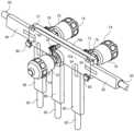
도 6은 다중의 도관 트랙이 서로에 그리고 또한 상이한 공정 구성요소에 연결되고 가요성 도관 또는 배관을 보유하는 실시예를 도시한다. 도관 트랙 및/또는 공정 구성요소를 장착하는 데 사용될 수 있는 스캐폴드 또는 지지 구조체가 도시된다.1A illustrates a system for managing flexible piping according to one embodiment. An exploded, perspective view of a single valve positioned between two segments of a conduit track is shown. A connector member connecting the two segments of the conduit track and the valve is also observed.
Figure 1B shows another exploded, perspective view of the system for managing the flexible piping shown in Figure 1A.
Figure 1C shows a schematic diagram of a valve actuator used to pinch flexible tubing. The pinching element extends to the flexible tubing and pinches it, thereby creating a “closed” condition. When the actuator is retracted, the flexible tubing is not pinched and thus creates an “open” state.
Figure 2A shows a perspective view of a system for managing flexible piping according to the embodiment of Figures 1A and 1B. The flexible conduit passes through the passageway of the valve and is positioned within the conduit channels of the two conduit tracks that support the valve. The connector extends the length of the conduit track and valve body.
Figure 2b shows an end view of the system of Figure 2a. The flexible conduit can be observed to be within the conduit channel. The connector is inserted into a connector channel located on opposite sides of the conduit channel.
Figure 3A shows another embodiment of a system for managing flexible piping, including multiple valves.
Figure 3b is a perspective view of the system of Figure 3a. This shows one valve located on one side of the valve assembly and also two valves located on the opposite side.
Figure 4A shows a perspective view of another multi-valve embodiment.
Figure 4b shows another perspective view of the multi-valve embodiment of Figure 4a.
Figure 4C shows another perspective view of the multi-valve embodiment of Figure 4A.
FIG. 5A depicts an embodiment in which multiple different shapes (or lengths) of conduit tracks can be combined with other process components (e.g., valves shown) to manage the position and orientation of flexible conduits. Figure 5a shows modular components before assembly.
Figure 5b shows the assembled components of Figure 5a.
Figure 6 shows an embodiment where multiple conduit tracks are connected to each other and also to different process components and carry flexible conduits or tubing. A scaffold or support structure that can be used to mount conduit tracks and/or process components is shown.
도 1a 및 1b는 일 실시예 따른 가요성 도관(예컨대, 배관)을 관리하는 시스템(10)을 도시한다. 본 명세서에 언급되는 바와 같이, 시스템(10)은 의약품, 화학약품, 바이오프로세스, 및 식품/유제품 제조 작업에 대한 구체적인 적용가능성을 갖는다. 시스템(10)은 예를 들어, 유체-기반 제조 공정에 사용되는 다양한 구성요소의 배치 및 물리적인 위치를 관리하는 데 사용된다. 도 1a 및 1b는 도관 트랙의 2개의 세그먼트(30, 32) 사이에 개재되어 그에 연결되는 밸브(12)를 도시한다. 가요성 도관(60)이 아래에 설명되는 바와 같이 밸브(12)를 통과하고 도관 트랙의 2개의 세그먼트(30, 32)의 적절한 위치에 고정되는 것으로 도시된다. 가요성 도관(60)은 전형적으로 그러나 비배타적으로 낮은 압력에 있는, 유체를 반송하는 데 사용된다. 가요성 도관(60)은 실리콘을 포함할 수 있지만 다른 재료가 사용될 수 있다. 이들은 예를 들어, 열가소성 탄성중합체(TPE), 열가소성 고무(TPR) 등과 같은 중합체를 포함한다. 가요성 도관(60)은 보강되지 않거나 보강될 수 있다. 가요성 도관(60)은 유체가 통과하는 중심 루멘을 포함한다. 가요성 도관(60)은 다양한 크기를 가질 수 있다. 예를 들어, 본 발명을 제한하지 않는다면, 가요성 도관(60)은 0.375 인치의 내경 그리고 0.625 인치의 외경을 가질 수 있다. 물론, 이것은 예시일 뿐이고, 다른 직경이 또한 사용될 수 있다. 본 발명은 사용되는 가요성 도관(60)의 크기에 의해 제한되지 않는다.1A and 1B illustrate a
도 1a 및 1b를 계속하여 참조하면, 밸브(12)가 가요성 도관(60) 주위에 고정되는 것으로 도시된다. 밸브(12)는 힌지(16)를 통해 힌지결합되는 제1 및 제2 본체 부분(14a, 14b)으로 구성되는 밸브 본체(14)를 포함한다. 밸브 본체(14)는 전형적으로 금속 재료로부터 제조되지만 그것은 또한 적절하게 경질인 플라스틱 또는 다른 중합체 재료로부터 형성될 수 있다. 제1 및 제2 본체 부분(14a, 14b)은 (도 1a 및 1b에 도시된 바와 같이) 폐쇄 상태에 있을 때에, 밸브 본체(14)를 통해 연장하고 가요성 도관(60)을 수용하는 통로(18)를 한정한다. 제1 및 제2 본체 부분(14a, 14b)은 체결구(19)를 사용하여 폐쇄 상태로 고정될 수 있다. 도 1a 및 1b에 도시된 바와 같은 체결구(19)는 나사형 래치 그리고 나사형 래치에 대해 조여지거나 느슨해져 밸브 본체(14)를 선택적으로 폐쇄/개방할 수 있는 노브를 포함할 수 있다. 통로(18)의 크기 및 형상은 가요성 도관(60)이 그 내에 정확하게 끼워지도록 되어 있다. 예를 들어, 통로(18)의 내경은 가요성 도관(60)의 외경과 거의 일치할 수 있다. 도 1a에서 관찰되는 바와 같이, 밸브 액추에이터(20)가 밸브 본체(14) 상에 배치된다. 이러한 실시예에서, 클램프(22)가 밸브 액추에이터(20)를 밸브 본체(14)에 고정하는 데 사용된다. 그러나, 클램프(22)의 사용은 임의적이다. 일부 실시예에서, 밸브 액추에이터(20)는 밸브 본체(14)와 직접적으로 합체될 수 있다. 액추에이터(20)는 도 1c에서 관찰되는 바와 같이 화살표의 방향으로 이동하여 가요성 도관(60)의 중심 루멘(62)을 선택적으로 폐쇄/개방하는 핀칭 요소(24)를 포함한다. 액추에이터(20)는 임의의 개수의 접근단계를 사용하여 이동될 수 있다. 예를 들어, 액추에이터(20)는 공기 포트(21)를 사용하는 공압 작동식 밸브일 수 있다. 액추에이터(20)는 또한 수동으로 회전되는 보닛(bonnet) 등을 사용하여 수동으로 전진/후퇴될 수 있다. 액추에이터(20)는 또한 보닛 등의 회전을 요구하지 않는 수동-작동식 토글-타입 기구를 사용하여 작동될 수 있다. 이것은 밸브를 온/오프 상태 사이에서 신속하게 전환할 수 있게 한다.With continued reference to FIGS. 1A and 1B ,
도 1a 및 1b를 계속하여 참조하면, 도관 트랙(30, 32)은 각각의 도관 트랙(30, 32)이 밸브(12)의 양쪽 대향 측면 상에 위치된 상태에서 밸브(12)에 인접한 것으로 도시된다. 도관 트랙(30, 32)은 가요성 도관(60)을 요구된 공간적인 구성(예컨대, 길이, 형상 등)에서 적절한 위치에 보유하는 데 사용된다. 도관 트랙(30, 32)은 임의의 재료(예컨대, 중합체 또는 플라스틱-계열)로 제조될 수 있고, 전형적으로 강성 또는 반-강성이다. 이러한 예에서, 도관 트랙(30, 32)은 직선형 트랙 세그먼트이지만 다른 형상이 사용될 수 있다(예컨대, 곡선부, 굴곡부 등이 트랙 내로 합체될 수 있다). 각각의 도관 트랙(30, 32)은 각각의 도관 트랙(30, 32)의 길이를 따라 연장하고 가요성 도관(60)을 수용하는 치수로 되어 있는 각각의 도관 채널(34, 36)을 포함한다. 도관 채널(34, 36)은 길이를 따라 (도시된 바와 같은) 연속형 또는 중단형일 수 있다. 이러한 실시예에서, 도관 채널(34, 36)은 C자형 또는 반-환형이고 그에 따라 가요성 도관(60)은 적절한 위치로 클리핑될(clipped) 수 있다. 가요성 도관(60)은 도관 채널(34, 36) 내로 가압되고, C자형 구조체에 의해 보유된다(가요성 도관(60)의 약간의 압축이 삽입 및 제거 중에 일어날 수 있다). 각각의 도관 채널(34, 36)의 개구는 가요성 도관(60)의 외경보다 작을 수 있고 그에 따라 가요성 도관(60)은 그 내에 견고하게 보유된다. 각각의 도관 트랙(30, 32)은 도 1a 및 1b에 도시된 바와 같이 각각의 커넥터 채널(38, 40)을 포함한다. 커넥터 채널(38, 40)은 도시된 실시예에서 도관 채널(34, 36)의 대향 측면 상에 위치된다. 각각의 커넥터 채널(38, 40)은 도관 채널(34, 36)로부터 연장하여 각각의 보유 탭(46, 48)에서 종료하는 한 쌍의 벽(42, 44)에 의해 형성된다. 보유 탭(46, 48)은 아래에 설명되는 바와 같이 커넥터 채널(38, 40) 내로 삽입되는 커넥터를 보유하는 데 사용된다.1A and 1B, conduit tracks 30, 32 are shown adjacent to
도 1a 및 1b에서 관찰되는 바와 같이, 커넥터(50)가 밸브 본체(14)를 도관 트랙(30, 32)에 연결하는 데 사용된다. 커넥터(50)는 밸브(12)를 인접 도관 트랙(30, 32)에 연결하는 데 사용되는 재료(예컨대, 중합체, 플라스틱-계열, 또는 심지어 금속)의 강성 편으로부터 형성될 수 있다. 도 1a 및 1b에서 관찰되는 바와 같이, 커넥터(50)는 커넥터(50)의 길이를 따라 연장하는 한 쌍의 보유 부재(54)를 갖는 기부(52)를 포함한다. 한 쌍의 보유 부재(54)는 도 1a에서 관찰되는 바와 같이 경사형 벽 또는 모서리를 포함할 수 있다. 보유 부재(54)는 커넥터(50)의 길이를 따라 연속형일 수 있거나 그것들은 중단형일 수 있다. 도 1a 및 1b에서의 보유 부재(54)는 커넥터 채널(38, 40) 내의 대응하는 탭(46, 48)과 결합하는 그 길이를 따른 대응하는 보유 탭(56)을 갖는다. 이러한 관점에서, 커넥터(50)는 커넥터 채널(38, 40) 및 밸브 본체(14)에 견고하게 고정된다. 밸브 본체(14)는 밸브 본체(14) 내에 위치되어 커넥터(50)의 보유 부재(54) 및 탭(56)과 결합하도록 구성되는 장착 채널(15)을 포함한다. 도 1a 및 1b에 도시된 바와 같은 장착 채널(15)은 보유 부재(54) 및 탭(56)과 결합하는 노치형 표면을 갖는 밸브 본체(14)의 2개의 절반부(14a, 14b) 중 하나 내에 위치되는 노치형 채널이다. 커넥터(50)는 커넥터 채널(38, 40) 및 장착 채널(15) 내로 측방으로 삽입될 수 있다. 대안으로서, 일부 실시예에서, 커넥터(50)는 커넥터 채널(38, 40) 및 장착 채널(15) 내로 직접적으로 가압될 수 있고 그에 의해 보유 부재(54)는 구부러지고 이어서 적절한 위치로 로킹된다(예컨대, 커넥터(50)는 장착 채널(15) 및 커넥터 채널(38, 40) 내로 가압된 후에 적절한 위치로 스냅결합된다).1A and 1B,
도 2a 및 2b는 가요성 도관(60)이 도관 채널(34, 36) 내로 삽입된 것으로 도시된 상태의 도 1a 및 1b의 실시예를 도시한다. 따라서, 가요성 도관(60)은 적절한 위치로 클리핑되거나 다른 방식으로 고정된다. 가요성 도관(60)은 우선 체결구(19)를 로킹해제하여 밸브 본체(14)를 개방함으로써 도관 채널(34, 36)로부터 제거될 수 있다. 가요성 도관(60)은 이어서 채널(34, 36)의 길이를 따라 측방으로 또는 가요성 도관(60)을 도관 채널(34, 36)의 클리핑 구조체로부터 강제로 제거하기에 충분한 힘을 가함으로써 횡단방향으로 도관 채널(34, 36)의 외부로 인출될 수 있다. 도 2a에서 가장 잘 관찰되는 바와 같이, 이러한 실시예에서, 커넥터(50)의 길이는 그것이 밸브 본체(14) 그리고 또한 도관 트랙(30, 32)을 횡단하도록 되어 있다는 것을 또한 주목하여야 한다. 커넥터(50)의 길이는 변할 수 있다. 대안적인 실시예에서, 다중의 커넥터(50)가 도관 트랙을 밸브 본체(14)에 연결하는 데 사용될 수 있다. 예를 들어, 도관 트랙(30)에 고정되는 제1 커넥터(50)가 장착 채널(15) 내로 부분적으로 연장할 수 있고 한편 다른 도관 트랙(32)에 고정되는 제2 커넥터(50)가 장착 채널(15) 내로 부분적으로 연장할 수 있다.Figures 2A and 2B show the embodiment of Figures 1A and 1B with
도 3a 및 3b는 다중의 밸브(74)를 보유하는 밸브 조립체(70)를 사용하는 시스템(10)의 또 다른 실시예를 도시하고, 여기서 다중의 밸브(74)는 클램프(78)를 사용하여 밸브 조립체(70)에 고정된다. 밸브 조립체(70)는 그것이 힌지(72) 또는 다중의 힌지(72)를 통해 연결되는 제1 절반부(70a) 및 제2 절반부(70b)를 갖는 밸브 본체를 포함한다는 점에서 이전의 실시예와 유사하다. 밸브 조립체(70)의 내부 표면은 가요성 도관(60)을 보유하는 통로를 한정한다. 이러한 실시예에서, 가요성 도관(60)은 주 라인과 더불어 여러 개의 분지(branch)를 포함한다. 따라서, 제1 및 제2 절반부(70a, 70b) 내의 통로는 이러한 분지형 구성에 대응하여 가요성 도관(60)을 포위한다. 밸브 조립체(70)는 이전의 실시예에 설명된 체결구(19)와 같은 다중의 체결구(80)를 사용하여 폐쇄 상태로 고정된다.3A and 3B illustrate another embodiment of
이러한 실시예에서, 밸브 조립체(70)에 고정되는 3개의 밸브(74)가 있다. 각각의 밸브(74)는 그 자체의 액추에이터(76)를 갖고, 도 1a 및 1b의 실시예에 대해 설명된 바와 같이 작용하는 핀칭 요소(도시되지 않음)를 동작시켜 가요성 도관(60)을 핀칭한다. 이러한 실시예에서, 밸브(74)는 밸브가 개방 또는 폐쇄되는지에 따라 유체가 다양한 분지 채널로 선택적으로 전환될 수 있도록 위치된다. 도 3a 및 3b에서 관찰되는 바와 같이, (이전에 설명된 바와 같이) 밸브 조립체(70)에 연결되고 가요성 도관(60)을 각각의 도관 채널 내에 수용하는 5개의 도관 트랙(84, 86, 88, 90, 92)이 있다. 이러한 실시예에서, 다양한 도관 트랙(84, 86, 88, 90, 92)을 밸브 조립체(70)에 연결하는 개별의 커넥터(94)가 있다. 대안으로서, 하나 이상의 커넥터가 다중의 도관 트랙(84, 86, 88, 90, 92) 내로 연장 및 삽입되면 더 적은 커넥터가 있을 수 있다. 커넥터(94)는 위에 설명된 이전의 실시예에서와 같이 형성될 수 있고, 이전에 설명된 바와 같이 밸브 조립체(70) 및 도관 트랙(84, 86, 88, 90, 92)과 인터페이싱될 수 있다. 대안으로서, 밸브 조립체(70)는 밸브 조립체(70) 내에 영구적으로 형성되고 도관 트랙(84, 86, 88, 90, 92)과 인터페이싱되는 커넥터(94)를 가질 수 있다. 예를 들어, 커넥터(94)는 도관 트랙(84, 86, 88, 90, 92) 내에 형성되는 대응하는 "암형" 채널 또는 슬롯(예컨대, 도 1a 및 1b의 커넥터 채널(38, 40))과 인터페이싱되는 "수형" 연장부 또는 커넥터를 포함할 수 있다. 또 다른 대안적인 구성에서, 도관 트랙(84, 86, 88, 90, 92)은 각각의 트랙에 고정되고 밸브 조립체(70) 내에 형성되는 암형 슬롯 또는 채널(예컨대, 도 1a 및 1b의 장착 채널(15))과 인터페이싱되는 수형 연장부 또는 커넥터(94)를 가질 수 있다. 커넥터(94)의 이들 대안적인 설계는 또한 위에 설명된 도 1a, 1b, 2a, 및 2b의 실시예에 사용될 수 있다. 3개의 밸브(74)가 도시되지만, 추가적인 또는 더 적은 밸브(74)가 있을 수 있고, 본 발명은 밸브(74)의 개수에 의해 제한되지 않는다.In this embodiment, there are three
도 4a-4c는 상부에 위치된 다중의 밸브(74)를 포함하는 밸브 조립체(70)를 갖는 시스템(10)의 또 다른 실시예를 도시한다. 이러한 실시예에서, 밸브 조립체(70) 상에 배치되거나 다른 방식으로 그에 연결되는 6개의 밸브(74)가 있다. 각각의 밸브(74)는 그 자체의 액추에이터(76)를 갖고, 도 1a 및 1b의 실시예에 대해 설명된 바와 같이 작용하는 핀칭 요소(도시되지 않음)를 동작시켜 힌지(72)를 통해 연결되는 밸브 조립체(70)의 2개의 절반부(70a, 70b) 사이에 위치되는 가요성 도관(60)을 핀칭한다. 체결구(80)(예컨대, 이전에 설명된 바와 같은 노브를 갖는 래치)가 밸브 조립체(70)의 2개의 절반부(70a, 70b)를 함께 고정하는 데 사용될 수 있다. 또한, 임의적인 클램프(78)가 도시된 바와 같이 밸브(74)를 밸브 조립체(70)에 고정하는 데 사용될 수 있다. 대안으로서, 밸브(74)는 밸브 조립체(70) 내로 직접적으로 포함될 수 있다. 이러한 실시예에서, 밸브(74)는 밸브가 개방 또는 폐쇄되는지에 따라 유체가 다양한 분지 채널로 선택적으로 전환될 수 있도록 위치된다. 도 4a에서 가장 잘 관찰되는 바와 같이, 밸브 조립체 절반부(70a) 내에 위치되어 핀칭 요소(예컨대, 도 1c의 핀칭 요소(24))의 통과를 가능케 하고 그에 따라 가요성 도관(60)이 핀칭(폐쇄) 또는 핀칭해제(개방)될 수 있는 구멍(77)이 있다. 2개의 그러한 구멍(77)이 주 통로(18a) 내에 위치되고 한편 4개의 구멍(77)이 분지 통로(18b) 내에 위치된다.Figures 4A-4C show another embodiment of
도 4a-4c에서 관찰되는 바와 같이, 밸브 조립체(70)에 연결되고 (이전에, 예를 들어, 도 1a, 1b, 2a, 및 2b에서 설명된 바와 같이) 가요성 도관(60)을 각각의 도관 채널 내에 수용하는 6개의 도관 트랙(84, 86, 88, 90, 92, 93)이 있다. 이러한 실시예에서, 다양한 도관 트랙(84, 86, 88, 90, 92, 93)을 밸브 조립체(70)에 연결하는 (이전에, 예를 들어, 도 1a, 1b, 2a, 및 2b에서 설명된 바와 같은) 6개의 개별의 커넥터(94)가 있다. 도 4b 및 4c에서 가장 잘 관찰되는 바와 같이, 장착 채널(15)이 밸브 조립체 절반부(70b) 내에 위치된다. 장착 채널(15)은 (이전에 설명된) 커넥터(94)의 대응하는 표면 및 탭과 결합하는 노치형 표면을 갖는 노치형 채널로서 형성된다. 커넥터(94)는 각각의 도관 트랙(84, 86, 88, 90, 92, 93)을 장착 채널(15)을 통해 밸브 조립체(70)에 연결한다. 하나의 대안적인 실시예에서, 도관 트랙(84, 93) 둘 모두를 연결하는 단일의 긴 커넥터(94)가 사용될 수 있다는 것을 주목하여야 한다.4A-4C, each
또 다른 대안적인 실시예에서, 커넥터(94)는 밸브 조립체(70)와 도관 트랙(84, 86, 88, 90, 92, 93) 사이의 인터페이스로부터 생략될 수 있다. 예를 들어, 밸브 조립체(70)는 밸브 조립체(70) 내에 합체되는 "커넥터"를 가질 수 있다. 이들은 예를 들어, 밸브 조립체(70) 내로 일체로 형성되어 도관 트랙(84, 86, 88, 90, 92, 93)의 커넥터 채널 내로 삽입되는 "수형" 연장부를 포함할 수 있다. 또 다른 대안예에서, 밸브 조립체(70)와 인터페이싱되는 도관 트랙(84, 86, 88, 90, 92, 93)은 장착 채널(15)과 합체되는 "수형" 단부를 가질 수 있다. 이들 대안적인 실시예는 도관 트랙(84, 86, 88, 90, 92, 93)과 밸브 조립체(70) 사이의 인터페이스에 있는 커넥터(94)를 가질 필요성을 제거할 것이다. 이들 대안적인 설계는 또한 도 1a, 1b, 2a, 및 2b의 실시예에 적용할 수 있다는 것을 주목하여야 한다.In another alternative embodiment,
도 5a 및 5b는 본 명세서에 설명되는 시스템(10)의 모듈형 특성을 도시한다. 다양한 구성요소가 다양한 조합 및 설정으로 혼합 및 연결되어 구성요소의 요구된 공간적인 배열을 성취할 수 있다. 도 5a 및 5b의 매우 기본적인 예에서, 단일의 밸브(100)가 2개의 직선형 도관 트랙(102, 104) 그리고 곡선형 도관 트랙 세그먼트(106)와 더불어 도시된다. 2개의 커넥터(108, 110)가 또한 도시된다. 도 5b의 최종적인 구성을 성취하기 위해, 2개의 직선형 도관 트랙(102, 104)은 커넥터(108)를 사용하여 서로에 연결된다. 다른 커넥터(110)는 직선형 도관 트랙(예컨대, 도관 트랙(104))의 하나의 단부에 연결되고, (예컨대, 도 1a에 도시된 형태의 장착 채널(15)을 사용하여) 밸브(100)를 통해 연장하고, 곡선형 도관 트랙 세그먼트(106)와 연결된다. 물론, 이러한 예는 시스템의 전체 구조의 매우 작은 부분을 도시할 뿐이다. 전체 제조 공정이 함께 연결되는 많은 상이한 구성요소를 가질 것으로 여길 수 있다. 따라서, 다양한 상이한 크기, 형상, 및 기하구조의 많은 도관 트랙이 채용될 수 있다. 또한, 본 명세서에 설명되는 실시예가 상이한 도관 트랙 사이에 위치되는 하나의 밸브 또는 다중의 밸브를 이용하였지만, 도관 트랙에 연결되는 다른 구성요소가 있을 수 있다. 이것은 예를 들어, 펌프, 센서, 필터, 크로마토그래피 칼럼, 반응 체적부(예컨대, 반응기), 저장조, 매니폴드 등을 포함한다.5A and 5B illustrate the modular nature of
내부에 수용된 가요성 도관(60)을 갖는 도관 트랙은 임의적으로 지지체 또는 스캐폴드 상에 장착되어 구성요소를 공간적으로 배열하는 것을 추가로 보조할 수 있다. 지지체 또는 스캐폴드는 제조 시설의 지면에, (예컨대, 현수상태로) 천장에, 또는 벽 상에 고정될 수 있다. 스캐폴드 또는 지지체는 또한 다른 적용분야를 위해 가동 카트 등 상에 위치될 수 있다. 도관 트랙은 집 타이(zip tie), 클립, 나사, 또는 심지어 접착제와 같은 다양한 상이한 체결구를 사용하여 장착될 수 있다. 도 6은 다중의 도관 트랙(120)이 서로에 그리고 또한 상이한 공정 구성요소(122)에 연결되는 실시예를 도시한다. 도시된 공정 구성요소(122)는 펌프(122a), 밸브(122b), 센서(122c), 및 칼럼(122d)을 포함하지만, 다른 공정 구성요소가 포함될 수 있다. 가요성 도관 또는 배관(60)이 도관 트랙(120) 내에 장착되고 다양한 공정 구성요소(122)를 통과하는 것으로 도시된다. 이러한 실시예에서, 도관 트랙(120) 및/또는 공정 구성요소(122)를 장착하는 데 사용될 수 있는 스캐폴드 또는 지지체(130)가 또한 도시된다.A conduit track with
본 명세서에 설명되는 실시예에서 관찰되는 바와 같이, 다양한 도관 트랙이 밸브 본체 또는 밸브 조립체에 인접하여 위치되는 것으로서 관찰된다. 이들 인접 도관 트랙은 밸브 본체 또는 밸브 조립체와 인접하지 않아도 된다는 것을 주목하여야 한다. 간극이 인접 도관 트랙과 밸브 본체/밸브 조립체 사이에 있을 수 있다. 물론, 다른 실시예에서, 도관 트랙은 밸브 본체/밸브 조립체와 물리적으로 인접할 수 있다. 또한, 밸브 본체/밸브 조립체가 커넥터와 인터페이싱되는 것으로서 설명되었지만, 일부의 대안적인 실시예에서, 밸브 본체/밸브 조립체는 별도의 커넥터에 대한 필요성 없이 도관 트랙에 직접적으로 고정될 수 있다. 또한, 도시된 실시예에서, 클램프(22, 78)가 다양한 밸브(12, 74) 및 액추에이터(20, 76)를 밸브 본체(14) 또는 밸브 조립체(70)에 연결하는 것으로 도시된다. 일부의 대안적인 실시예에서, 클램프가 없고, 관련된 액추에이터(20, 76)를 갖는 밸브(12, 74)가 밸브 본체(14) 또는 밸브 조립체(70)에 직접적으로 고정된다.As observed in the embodiments described herein, various conduit tracks are observed to be located adjacent to the valve body or valve assembly. It should be noted that these adjacent conduit tracks need not be adjacent to the valve body or valve assembly. A gap may exist between an adjacent conduit track and the valve body/valve assembly. Of course, in other embodiments, the conduit track may be physically adjacent to the valve body/valve assembly. Additionally, although the valve body/valve assembly is described as being interfaced with a connector, in some alternative embodiments, the valve body/valve assembly may be secured directly to the conduit track without the need for a separate connector. Additionally, in the depicted embodiment, clamps 22, 78 are shown connecting the
본 출원인은 액체-기반 제조 공정의 일부로서 사용되는 가요성 도관을 구성 및 배치하는 데 사용될 수 있는 가요성 도관 관리 시스템을 위와 같이 설명하였다. 도관 트랙은 가요성 도관을 고정된 위치에 그리고 요구된 형상으로 고정하는 데 사용된다. 각각의 도관 트랙은 가요성 도관을 보유하는 도관 채널을 포함한다. 가요성 도관은 도관 채널 내부로 그리고 외부로 용이하게 적재될 수 있다. 예를 들어, 무균 또는 살균 적용분야를 위해, 가요성 도관은 동일한 도관 트랙을 사용하면서 또 다른 가요성 도관으로 신속하게 교체될 수 있다. 도관 트랙은 강성 또는 반-강성 커넥터를 수용하는 슬롯을 한정하는 벽 등을 갖는 커넥터 채널을 대향 측면 상에 포함한다. 커넥터는 도관 트랙이 다른 도관 트랙 또는 밸브, 펌프, 필터, 칼럼, 저장조, 센서 등과 같은 다른 공정 구성요소에 연결될 수 있게 한다. 예를 들어, 공정 구성요소는 커넥터를 수용하고 그에 따라 도관 채널이 공정 구성요소에 대해 고정될 수 있는 장착 채널 또는 다른 슬롯을 가질 수 있다. 커넥터는 도관 트랙 또는 다른 공정 구성요소 상의 슬롯 또는 채널 내로 삽입되는 설부(tongue)로서 작용한다. 다양한 길이의 가요성 도관이 사용될 수 있다. 예를 들어, 가요성 도관의 다중의 세그먼트는 사용될 수 있는 클램프와 같은 표준형 커넥터를 사용하여 서로에 연결될 수 있다. 대안으로서, 많은 도관 트랙 및 공정 구성요소를 횡단하는 긴 길이의 가요성 도관이 사용될 수 있다.Applicants have described above a flexible conduit management system that can be used to construct and position flexible conduits used as part of a liquid-based manufacturing process. Conduit tracks are used to hold flexible conduits in fixed positions and in the desired shape. Each conduit track includes a conduit channel holding a flexible conduit. Flexible conduits can be easily loaded into and out of the conduit channel. For example, for aseptic or sterile applications, a flexible conduit can be quickly replaced with another flexible conduit while using the same conduit track. The conduit track includes connector channels on opposite sides having walls and the like defining slots that receive rigid or semi-rigid connectors. Connectors allow a conduit track to be connected to another conduit track or to other process components such as valves, pumps, filters, columns, reservoirs, sensors, etc. For example, the process component may have a mounting channel or other slot that can receive a connector and thereby allow the conduit channel to be secured to the process component. The connector acts as a tongue that is inserted into a slot or channel on a conduit track or other process component. Flexible conduits of various lengths may be used. For example, multiple segments of flexible conduit can be connected to each other using standard connectors, such as clamps, which can be used. Alternatively, long lengths of flexible conduit that traverse many conduit tracks and process components may be used.
본 명세서에 설명되는 실시예에서, 커넥터는 개별형일 수 있고 그러한 경우에 그것들은 도관 트랙 상의 다양한 커넥터 채널 또는 공정 구성요소 상의 장착 채널 내로 삽입된다. 대안으로서, 커넥터는 도관 트랙 또는 공정 구성요소에 고정될 수 있고, 인접 구성요소의 커넥터 채널 또는 장착 채널 내로 삽입될 수 있다. 다양한 실시예가 본 명세서에 설명되지만, 하나의 실시예의 다양한 특징이 또 다른 실시예와 조합 또는 사용될 수 있다는 이해되어야 한다. 즉, 하나의 실시예의 특징이 또 다른 실시예에서 치환 또는 사용될 수 있다. 본 발명의 실시예가 예시 및 설명되었지만, 다양한 변형이 본 발명의 범주로부터 벗어나지 않고도 행해질 수 있다. 따라서, 본 발명은 하기의 청구범위, 및 그 등가물을 제외하면, 제한되지 않아야 한다.In embodiments described herein, the connectors may be discrete, in which case they are inserted into various connector channels on conduit tracks or mounting channels on process components. Alternatively, the connector may be secured to a conduit track or process component and inserted into the connector channel or mounting channel of an adjacent component. Although various embodiments are described herein, it should be understood that various features of one embodiment may be combined or used with another embodiment. That is, features of one embodiment may be substituted or used in another embodiment. Although embodiments of the invention have been illustrated and described, various modifications may be made without departing from the scope of the invention. Accordingly, the present invention is not to be limited, except for the following claims and their equivalents.
Claims (21)
Translated fromKorean가요성 실리콘 또는 중합체 도관 또는 배관의 세그먼트; 및
복수의 도관 트랙을 포함하고,
각각의 도관 트랙은 그 제1 측면 상에 배치되고 각각의 도관 트랙의 길이를 따라 연장하며 가요성 실리콘 또는 중합체 도관 또는 배관의 세그먼트를 내부에 수용하는 치수로 되어 있는 개방된 도관 채널을 포함하고, 각각의 도관 트랙은 대향하는 제2 측면 상에 배치되고 각각의 도관 트랙의 길이를 따라 연장하며 인접 도관 트랙을 연결하는 하나 이상의 커넥터를 수용하는 커넥터 채널을 추가로 포함하고, 각각의 커넥터는 그 길이를 따라 연장하며 기부에 직교하지 않도록 배치된 한 쌍의 경사형 벽 또는 모서리를 갖고 도관 트랙 내의 대응하는 탭과 결합하도록 형성된 탭을 갖는 기부를 포함하는, 시스템.A system for managing flexible conduits or piping used in pharmaceutical, bioprocess, or food applications.
segments of flexible silicone or polymer conduit or tubing; and
comprising a plurality of conduit tracks;
Each conduit track is disposed on a first side thereof and includes an open conduit channel extending along the length of each conduit track and dimensioned to receive therein a segment of flexible silicone or polymer conduit or tubing, Each conduit track further includes a connector channel disposed on the opposing second side and extending along the length of each conduit track and receiving one or more connectors connecting adjacent conduit tracks, each connector extending its length. A system comprising a base extending along and having a pair of inclined walls or edges disposed not perpendicular to the base and having tabs formed to engage corresponding tabs in the conduit track.
하나 이상의 커넥터로 단부-단부 방식으로 서로에 연결되게 구성되는 복수의 도관 트랙으로서, 각각의 도관 트랙은 그 제1 측면 상에 배치되고 각각의 도관 트랙의 길이를 따라 연장하며 실리콘 또는 중합체 가요성 도관 또는 배관을 내부에 수용하는 치수로 되어 있는 개방된 도관 채널을 포함하고, 각각의 도관 트랙은 대향하는 제2 측면 상에 배치되고 각각의 도관 트랙의 길이를 따라 연장하며 하나 이상의 커넥터를 수용하는 커넥터 채널을 추가로 포함하는, 복수의 도관 트랙;
복수의 도관 트랙의 개방된 도관 채널 내에 배치되는 가요성 실리콘 또는 중합체 도관 또는 배관
을 포함하고; 및
각각의 커넥터는 그 길이를 따라 연장하며 기부에 직교하지 않도록 배치된 한 쌍의 경사형 벽 또는 모서리를 갖고 도관 트랙 내의 대응하는 탭과 결합하도록 형성된 탭을 갖는 기부를 포함하는, 시스템.A system for managing flexible conduits or piping used in pharmaceutical, bioprocess, or food applications.
A plurality of conduit tracks configured to be connected to each other in an end-to-end manner with one or more connectors, each conduit track disposed on a first side thereof and extending along the length of each conduit track and comprising a silicone or polymer flexible conduit. or an open conduit channel dimensioned to receive tubing therein, each conduit track disposed on an opposing second side and extending along the length of each conduit track and receiving one or more connectors. a plurality of conduit tracks, further comprising channels;
Flexible silicone or polymer conduit or tubing disposed within open conduit channels of a plurality of conduit tracks
Includes; and
A system, wherein each connector includes a base extending along its length and having a pair of sloped walls or edges disposed not perpendicular to the base and having tabs formed to engage corresponding tabs in the conduit track.
하나 이상의 커넥터로 단부-단부 방식으로 서로에 연결되게 구성되는 복수의 도관 트랙으로서, 각각의 도관 트랙은 그 제1 측면 상에 배치되고 각각의 도관 트랙의 길이를 따라 연장하며 가요성 도관 또는 배관을 내부에 수용하는 치수로 되어 있는 도관 채널을 포함하고, 각각의 도관 트랙은 대향하는 제2 측면 상에 배치되고 각각의 도관 트랙의 길이를 따라 연장하며 하나 이상의 커넥터를 수용하는 커넥터 채널을 추가로 포함하는, 복수의 도관 트랙;
복수의 도관 트랙의 도관 채널 내에 배치되는 가요성 도관 또는 배관; 및
가요성 도관 또는 배관을 내부에 수용하고 도관 트랙 중 하나 이상과 인터페이싱되는 밸브 본체 또는 밸브 조립체를 포함하고;
밸브 본체 또는 밸브 조립체는 장착 채널을 포함하고, 커넥터는 커넥터의 길이를 따라 연장하고 장착 채널과 결합하도록 구성되는 한 쌍의 보유 부재를 갖는 기부를 포함하는, 시스템.A system for managing flexible conduits or piping used in pharmaceutical, bioprocess, or food applications.
A plurality of conduit tracks configured to be connected to each other in an end-to-end manner with one or more connectors, each conduit track disposed on a first side thereof and extending along the length of each conduit track and forming a flexible conduit or tubing. a conduit channel dimensioned to receive therein, each conduit track disposed on an opposing second side and further comprising a connector channel extending along the length of each conduit track and receiving one or more connectors. a plurality of conduit tracks;
a flexible conduit or tubing disposed within the conduit channels of the plurality of conduit tracks; and
comprising a valve body or valve assembly receiving therein a flexible conduit or tubing and interfacing with one or more of the conduit tracks;
A system wherein the valve body or valve assembly includes a mounting channel, and the connector includes a base extending along the length of the connector and having a pair of retaining members configured to engage the mounting channel.
힌지에서 서로에 연결되는 제1 본체 부분 및 제2 본체 부분을 갖는 힌지형 밸브 본체를 포함하는 밸브로서, 제1 본체 부분 및 제2 본체 부분은 폐쇄 상태에 있을 때에, 밸브 본체를 통해 연장하는 통로를 한정하고, 밸브는 밸브 본체 상에 배치되고 통로 내부 및 외부로 선택적으로 이동하도록 구성되는 핀칭 요소를 갖는 액추에이터를 추가로 포함하고, 제1 본체 부분 및 제2 본체 부분 중 하나가 그 내에 배치되고 통로의 방향을 따라 배향되는 장착 채널을 포함하는, 밸브;
밸브 본체의 통로를 통해 연장하는 가요성 도관 또는 배관;
밸브 본체의 하나의 측면 상에 배치되는 제1 도관 트랙으로서, 제1 도관 트랙은 제1 도관 트랙의 길이를 따라 연장하며 가요성 도관 또는 배관을 내부에 수용하는 치수로 되어 있는 도관 채널을 포함하고, 제1 도관 트랙은 제1 도관 트랙의 길이를 따라 연장하는 커넥터 채널을 추가로 포함하는, 제1 도관 트랙;
밸브 본체의 대향 측면 상에 배치되는 제2 도관 트랙으로서, 제2 도관 트랙은 제2 도관 트랙의 길이를 따라 연장하며 가요성 도관 또는 배관을 내부에 수용하는 치수로 되어 있는 도관 채널을 포함하고, 제2 도관 트랙은 제2 도관 트랙의 길이를 따라 연장하는 커넥터 채널을 추가로 포함하는, 제2 도관 트랙; 및
장착 채널 내에 배치되고 제1 도관 트랙의 커넥터 채널 그리고 제2 도관 트랙의 커넥터 채널 내로 연장하며, 밸브 본체가 이에 고정되는, 적어도 하나의 커넥터
를 포함하는, 시스템.A system for managing flexible conduits or piping used in pharmaceutical, bioprocess, or food applications.
A valve comprising a hinged valve body having a first body portion and a second body portion connected to each other at a hinge, the first body portion and the second body portion having a passageway extending through the valve body when in a closed state. Defining that, the valve further includes an actuator disposed on the valve body and having a pinching element configured to move selectively in and out of the passageway, wherein one of the first body portion and the second body portion is disposed therein; A valve comprising a mounting channel oriented along the direction of the passageway;
A flexible conduit or tubing extending through a passageway in the valve body;
A first conduit track disposed on one side of the valve body, the first conduit track extending along the length of the first conduit track and comprising a conduit channel dimensioned to receive therein a flexible conduit or tubing; a first conduit track, the first conduit track further comprising a connector channel extending along the length of the first conduit track;
a second conduit track disposed on an opposite side of the valve body, the second conduit track extending along the length of the second conduit track and comprising a conduit channel dimensioned to receive therein a flexible conduit or tubing; a second conduit track, the second conduit track further comprising a connector channel extending along the length of the second conduit track; and
at least one connector disposed within the mounting channel and extending into the connector channel of the first conduit track and the connector channel of the second conduit track, the valve body being secured thereto;
system, including.
가요성 도관 또는 배관의 세그먼트를 제거하는 단계 및 가요성 도관 또는 배관의 다른 세그먼트를 복수의 도관 트랙의 도관 채널 내로 삽입하는 단계를 포함하는, 방법.This is a method of using the system in Paragraph 13,
A method comprising removing a segment of flexible conduit or tubing and inserting another segment of flexible conduit or tubing into a conduit channel of a plurality of conduit tracks.
Applications Claiming Priority (3)
| Application Number | Priority Date | Filing Date | Title |
|---|---|---|---|
| US201562218974P | 2015-09-15 | 2015-09-15 | |
| US62/218,974 | 2015-09-15 | ||
| PCT/US2016/051714WO2017048831A1 (en) | 2015-09-15 | 2016-09-14 | Flexible tubing management system for pharmaceutical, bioprocess applications, and food/dairy applications |
Publications (2)
| Publication Number | Publication Date |
|---|---|
| KR20180052716A KR20180052716A (en) | 2018-05-18 |
| KR102653403B1true KR102653403B1 (en) | 2024-04-02 |
Family
ID=58289848
Family Applications (1)
| Application Number | Title | Priority Date | Filing Date |
|---|---|---|---|
| KR1020187010190AActiveKR102653403B1 (en) | 2015-09-15 | 2016-09-14 | Flexible piping management systems for pharmaceutical, bioprocess applications, and food/dairy applications |
Country Status (6)
| Country | Link |
|---|---|
| US (3) | US10612681B2 (en) |
| EP (2) | EP3950042A1 (en) |
| JP (2) | JP6955769B2 (en) |
| KR (1) | KR102653403B1 (en) |
| CN (1) | CN108025168B (en) |
| WO (1) | WO2017048831A1 (en) |
Families Citing this family (9)
| Publication number | Priority date | Publication date | Assignee | Title |
|---|---|---|---|---|
| KR102653403B1 (en)* | 2015-09-15 | 2024-04-02 | 리플리겐 코포레이션 | Flexible piping management systems for pharmaceutical, bioprocess applications, and food/dairy applications |
| KR102547782B1 (en) | 2017-01-31 | 2023-06-23 | 알피니티 유에스에이, 인크. | Bioprocess vessel with integral pump |
| EP3381529A1 (en) | 2017-03-29 | 2018-10-03 | EMD Millipore Corporation | Facility for treating a biological fluid |
| EP3381530A1 (en) | 2017-03-29 | 2018-10-03 | EMD Millipore Corporation | Facility for treating a biological fluid |
| CN109578691B (en)* | 2018-12-25 | 2020-07-24 | 嵊州市越通非开挖建设有限公司 | Be used for inclined plane pipeline integral erection device |
| HUE068931T2 (en)* | 2019-01-22 | 2025-02-28 | Adventia Pharma S L | Feeding cap, drive head, and drive system |
| US20240033179A1 (en)* | 2020-09-22 | 2024-02-01 | Alphinity Usa, Inc. | Systems and methods for the preparation of fluids for bioprocess and pharmaceutical applications |
| CN114576387B (en)* | 2022-02-17 | 2024-08-13 | 马俊 | Fluid hose clamp pipe valve |
| US20250116349A1 (en)* | 2023-10-09 | 2025-04-10 | Repligen Corporation | Pneumatic actuator assembly for reduced dead leg |
Citations (2)
| Publication number | Priority date | Publication date | Assignee | Title |
|---|---|---|---|---|
| DE4224167A1 (en)* | 1992-07-22 | 1994-01-27 | Bundesrep Deutschland | Retainer for two catheter connection of one or more vein catheters - comprises flat carrier made up of two detachable parallel strips and having clamps and channel on its upper side which accommodates connection |
| JP2011027242A (en) | 2009-07-29 | 2011-02-10 | Bridgestone Corp | Header fixture and header fixing structure |
Family Cites Families (53)
| Publication number | Priority date | Publication date | Assignee | Title |
|---|---|---|---|---|
| US2825524A (en)* | 1956-12-17 | 1958-03-04 | Knox P Fox | Pinch valve |
| US2931387A (en) | 1957-08-22 | 1960-04-05 | Robertson Co H H | Control apparatus for domestic water distribution system |
| GB1055426A (en) | 1963-11-22 | 1967-01-18 | Kelsto Engineering Company Ltd | Improvements in or relating to pinch valves |
| US4254797A (en) | 1979-01-26 | 1981-03-10 | Bi-M Instrument Company | Apparatus for producing calibration gases suitable for analytical instrumentation |
| US4993456A (en) | 1982-03-02 | 1991-02-19 | Akos Sule | Pinch valve assembly |
| US4618114A (en)* | 1982-09-29 | 1986-10-21 | Lof Plastics Inc. | Conduit spacer and support |
| FR2576386B1 (en)* | 1985-01-18 | 1987-03-20 | Lesourd Hugues | TAP CONNECTED TO AT LEAST TWO SUPPLY PIPES, IN PARTICULAR FOR SANITARY FACILITIES AND SERVING SEPARATE OR MIXED OF AT LEAST TWO DIFFERENT LIQUIDS |
| JPS647979U (en) | 1987-07-03 | 1989-01-17 | ||
| US4895341A (en) | 1988-09-30 | 1990-01-23 | Whitey Co. | Pinch valve |
| US5078683A (en)* | 1990-05-04 | 1992-01-07 | Block Medical, Inc. | Programmable infusion system |
| US5165874A (en)* | 1990-05-04 | 1992-11-24 | Block Medical, Inc. | Disposable infusion apparatus and peristaltic pump for use therewith |
| US5197708A (en) | 1992-08-11 | 1993-03-30 | Flow-Rite Controls, Ltd. | Tubing pinch valve device |
| US5402823A (en) | 1992-12-07 | 1995-04-04 | George S. Cole & Associates, Incorporated | Pinch valve |
| US5350290A (en) | 1993-01-19 | 1994-09-27 | Amf Machinery Systems, Inc. | Manifold and valving arrangement for dough divider |
| US5549134A (en) | 1994-05-27 | 1996-08-27 | Marcvalve Corporation | Diaphragm valve |
| JP3486238B2 (en)* | 1994-09-21 | 2004-01-13 | Smc株式会社 | Switching valve |
| EP0847509A1 (en)* | 1995-09-21 | 1998-06-17 | Abbott Laboratories | Tension responsive pinch valve |
| US6068751A (en) | 1995-12-18 | 2000-05-30 | Neukermans; Armand P. | Microfluidic valve and integrated microfluidic system |
| US5901745A (en)* | 1997-06-19 | 1999-05-11 | The Hoover Company | Multi-solution dispensing valve |
| JP2002510378A (en) | 1997-07-03 | 2002-04-02 | プレシジョン・ディスペンシング・システムズ・リミテッド | Flexible tube tightening mechanism |
| JP4023638B2 (en)* | 1997-09-17 | 2007-12-19 | 因幡電機産業株式会社 | Piping cover |
| US6036166A (en) | 1997-09-25 | 2000-03-14 | Imi Cornelius Inc. | Chamber valve |
| IT1297329B1 (en) | 1997-11-26 | 1999-09-01 | Teseo Srl | SYSTEM OF ELEMENTS FOR THE FORMATION OF MODULAR PIPES IN EXTRUDED PROFILE |
| CN1289851C (en) | 1998-03-05 | 2006-12-13 | 斯瓦戈洛克公司 | Manifold system |
| WO1999059392A2 (en)* | 1998-05-18 | 1999-11-25 | The Swagelok Company | Modular surface mount manifold assemblies |
| US7048007B2 (en)* | 1998-03-05 | 2006-05-23 | Swagelok Company | Modular surface mount manifold assemblies |
| US6036107A (en)* | 1998-03-31 | 2000-03-14 | Spraying System Co. | Control valve arrangement for spraying systems |
| WO2000025049A1 (en) | 1998-10-23 | 2000-05-04 | Chemand Corporation | Fluid handling port array |
| DE10035763B4 (en) | 2000-07-22 | 2006-07-27 | Nucellsys Gmbh | Device for dosing a gaseous medium |
| US7500949B2 (en)* | 2002-03-01 | 2009-03-10 | Medtronic Minimed, Inc. | Multilumen catheter |
| US7104275B2 (en) | 2002-04-01 | 2006-09-12 | Emerson Electric Co. | Pinch valve |
| US20040163711A1 (en) | 2003-02-20 | 2004-08-26 | Graham Packaging Company, L.P. | Fluid regulating pinch valve |
| JP2004293769A (en) | 2003-03-28 | 2004-10-21 | Japan Aviation Electronics Industry Ltd | Flow controller |
| US6799607B1 (en) | 2003-06-18 | 2004-10-05 | Pbm, Inc. | Sanitary conduit support systems and methods |
| US6976664B2 (en) | 2003-08-11 | 2005-12-20 | Mitos Technologies, Inc. | Free flow valve and element |
| US8038639B2 (en) | 2004-11-04 | 2011-10-18 | Baxter International Inc. | Medical fluid system with flexible sheeting disposable unit |
| US7048008B2 (en)* | 2004-04-13 | 2006-05-23 | Ultra Clean Holdings, Inc. | Gas-panel assembly |
| JP4597564B2 (en)* | 2004-04-28 | 2010-12-15 | 矢崎総業株式会社 | Clip structure and fixing method |
| US7383853B2 (en) | 2004-09-07 | 2008-06-10 | Parker-Hannifin Corp. | Multi-port free flow valve and element |
| US7819139B2 (en) | 2005-07-14 | 2010-10-26 | Pdc Facilities, Inc. | Liner for a flow meter |
| US20070295867A1 (en) | 2006-06-21 | 2007-12-27 | Hennon John | Conduit support apparatus |
| WO2008011132A2 (en) | 2006-07-21 | 2008-01-24 | Amgen, Inc. | Rupture valve |
| JP4994082B2 (en) | 2007-03-30 | 2012-08-08 | 旭有機材工業株式会社 | Piping material |
| US8091455B2 (en) | 2008-01-30 | 2012-01-10 | Cummins Filtration Ip, Inc. | Apparatus, system, and method for cutting tubes |
| FR2939348B1 (en) | 2008-12-10 | 2014-10-10 | Sartorius Stedim Biotech Sa | SECTIONING A FLEXIBLE TUBE FOR BIOPHARMACEUTICAL APPLICATIONS |
| US8282046B2 (en)* | 2009-02-12 | 2012-10-09 | Becton, Dickinson And Company | Systems and methods for organizing and priming an IV administration set |
| US8235067B2 (en) | 2009-05-15 | 2012-08-07 | Alphabio, Inc. | Encapsulated valve system |
| DE102010043865A1 (en)* | 2009-11-30 | 2011-07-14 | Horiba Stec Co., Ltd. | Fluid device |
| FR2961711B1 (en)* | 2010-06-23 | 2012-08-17 | Millipore Corp | POCKET FOR CIRCUIT OF A BIOLOGICAL LIQUID TREATMENT FACILITY |
| US8979070B2 (en)* | 2010-09-10 | 2015-03-17 | William Keizer | Clamshell housing for dispensing tube of metering dispenser |
| FR2970315A1 (en)* | 2011-01-07 | 2012-07-13 | Peugeot Citroen Automobiles Sa | Reinforcement device for flexible element i.e. hose, of brake fluid reservoir for connecting reservoir to master cylinder within engine compartment of car, has reinforcement unit mounted on flexible element in removable manner |
| US20120286110A1 (en)* | 2011-05-10 | 2012-11-15 | Hill Douglas C | Conduit support |
| KR102653403B1 (en)* | 2015-09-15 | 2024-04-02 | 리플리겐 코포레이션 | Flexible piping management systems for pharmaceutical, bioprocess applications, and food/dairy applications |
- 2016
- 2016-09-14KRKR1020187010190Apatent/KR102653403B1/enactiveActive
- 2016-09-14USUS15/759,794patent/US10612681B2/enactiveActive
- 2016-09-14EPEP21174602.9Apatent/EP3950042A1/ennot_activeWithdrawn
- 2016-09-14JPJP2018513355Apatent/JP6955769B2/ennot_activeExpired - Fee Related
- 2016-09-14CNCN201680053229.9Apatent/CN108025168B/enactiveActive
- 2016-09-14WOPCT/US2016/051714patent/WO2017048831A1/ennot_activeCeased
- 2016-09-14EPEP16847224.9Apatent/EP3349843B1/enactiveActive
- 2020
- 2020-02-18USUS16/794,160patent/US11231120B2/enactiveActive
- 2021
- 2021-08-17USUS17/404,495patent/US11578809B2/enactiveActive
- 2021-09-27JPJP2021156313Apatent/JP7278639B2/enactiveActive
Patent Citations (2)
| Publication number | Priority date | Publication date | Assignee | Title |
|---|---|---|---|---|
| DE4224167A1 (en)* | 1992-07-22 | 1994-01-27 | Bundesrep Deutschland | Retainer for two catheter connection of one or more vein catheters - comprises flat carrier made up of two detachable parallel strips and having clamps and channel on its upper side which accommodates connection |
| JP2011027242A (en) | 2009-07-29 | 2011-02-10 | Bridgestone Corp | Header fixture and header fixing structure |
Also Published As
| Publication number | Publication date |
|---|---|
| JP6955769B2 (en) | 2021-10-27 |
| EP3349843A1 (en) | 2018-07-25 |
| JP2022003272A (en) | 2022-01-11 |
| JP7278639B2 (en) | 2023-05-22 |
| US11231120B2 (en) | 2022-01-25 |
| US20200326004A1 (en) | 2020-10-15 |
| CN108025168B (en) | 2021-05-04 |
| JP2018534491A (en) | 2018-11-22 |
| US20210372540A1 (en) | 2021-12-02 |
| EP3349843B1 (en) | 2021-06-30 |
| EP3349843A4 (en) | 2019-05-15 |
| US10612681B2 (en) | 2020-04-07 |
| WO2017048831A1 (en) | 2017-03-23 |
| EP3950042A1 (en) | 2022-02-09 |
| CN108025168A (en) | 2018-05-11 |
| KR20180052716A (en) | 2018-05-18 |
| US20180252326A1 (en) | 2018-09-06 |
| US11578809B2 (en) | 2023-02-14 |
Similar Documents
| Publication | Publication Date | Title |
|---|---|---|
| KR102653403B1 (en) | Flexible piping management systems for pharmaceutical, bioprocess applications, and food/dairy applications | |
| US20240133472A1 (en) | Valve assembly with directional flow path | |
| US11719348B2 (en) | Encapsulated valve system and method of use | |
| EP2831474B1 (en) | Device for delivery of sample fluid |
Legal Events
| Date | Code | Title | Description |
|---|---|---|---|
| PA0105 | International application | Patent event date:20180411 Patent event code:PA01051R01D Comment text:International Patent Application | |
| PG1501 | Laying open of application | ||
| PA0201 | Request for examination | Patent event code:PA02012R01D Patent event date:20210716 Comment text:Request for Examination of Application | |
| PN2301 | Change of applicant | Patent event date:20221031 Comment text:Notification of Change of Applicant Patent event code:PN23011R01D | |
| E902 | Notification of reason for refusal | ||
| PE0902 | Notice of grounds for rejection | Comment text:Notification of reason for refusal Patent event date:20230627 Patent event code:PE09021S01D | |
| E701 | Decision to grant or registration of patent right | ||
| PE0701 | Decision of registration | Patent event code:PE07011S01D Comment text:Decision to Grant Registration Patent event date:20231227 | |
| GRNT | Written decision to grant | ||
| PR0701 | Registration of establishment | Comment text:Registration of Establishment Patent event date:20240327 Patent event code:PR07011E01D | |
| PR1002 | Payment of registration fee | Payment date:20240328 End annual number:3 Start annual number:1 | |
| PG1601 | Publication of registration |