KR102652930B1 - Surgical instrument to complement robotic artificial joint surgery - Google Patents
Surgical instrument to complement robotic artificial joint surgeryDownload PDFInfo
- Publication number
- KR102652930B1 KR102652930B1KR1020230166358AKR20230166358AKR102652930B1KR 102652930 B1KR102652930 B1KR 102652930B1KR 1020230166358 AKR1020230166358 AKR 1020230166358AKR 20230166358 AKR20230166358 AKR 20230166358AKR 102652930 B1KR102652930 B1KR 102652930B1
- Authority
- KR
- South Korea
- Prior art keywords
- femur
- cutting guide
- chamfer
- auxiliary frame
- posterior
- Prior art date
- Legal status (The legal status is an assumption and is not a legal conclusion. Google has not performed a legal analysis and makes no representation as to the accuracy of the status listed.)
- Active
Links
Images


Classifications
- A—HUMAN NECESSITIES
- A61—MEDICAL OR VETERINARY SCIENCE; HYGIENE
- A61B—DIAGNOSIS; SURGERY; IDENTIFICATION
- A61B17/00—Surgical instruments, devices or methods
- A61B17/14—Surgical saws
- A61B17/15—Guides therefor
- A61B17/154—Guides therefor for preparing bone for knee prosthesis
- A—HUMAN NECESSITIES
- A61—MEDICAL OR VETERINARY SCIENCE; HYGIENE
- A61B—DIAGNOSIS; SURGERY; IDENTIFICATION
- A61B17/00—Surgical instruments, devices or methods
- A61B17/14—Surgical saws
- A61B17/15—Guides therefor
- A—HUMAN NECESSITIES
- A61—MEDICAL OR VETERINARY SCIENCE; HYGIENE
- A61B—DIAGNOSIS; SURGERY; IDENTIFICATION
- A61B17/00—Surgical instruments, devices or methods
- A61B17/16—Instruments for performing osteoclasis; Drills or chisels for bones; Trepans
- A61B17/17—Guides or aligning means for drills, mills, pins or wires
- A61B17/1739—Guides or aligning means for drills, mills, pins or wires specially adapted for particular parts of the body
- A61B17/1764—Guides or aligning means for drills, mills, pins or wires specially adapted for particular parts of the body for the knee
- A—HUMAN NECESSITIES
- A61—MEDICAL OR VETERINARY SCIENCE; HYGIENE
- A61B—DIAGNOSIS; SURGERY; IDENTIFICATION
- A61B34/00—Computer-aided surgery; Manipulators or robots specially adapted for use in surgery
- A61B34/30—Surgical robots
Landscapes
- Health & Medical Sciences (AREA)
- Surgery (AREA)
- Life Sciences & Earth Sciences (AREA)
- Engineering & Computer Science (AREA)
- Medical Informatics (AREA)
- General Health & Medical Sciences (AREA)
- Veterinary Medicine (AREA)
- Public Health (AREA)
- Biomedical Technology (AREA)
- Heart & Thoracic Surgery (AREA)
- Nuclear Medicine, Radiotherapy & Molecular Imaging (AREA)
- Molecular Biology (AREA)
- Animal Behavior & Ethology (AREA)
- Dentistry (AREA)
- Oral & Maxillofacial Surgery (AREA)
- Orthopedic Medicine & Surgery (AREA)
- Robotics (AREA)
- Surgical Instruments (AREA)
- Prostheses (AREA)
- Physical Education & Sports Medicine (AREA)
- Transplantation (AREA)
Abstract
Translated fromKoreanDescription
Translated fromKorean본 발명은 로봇을 이용한 무릎 인공관절 전치환술(TKA, Total Knee Arthroplasty)에 있어서, 시술자(의사)가 로봇을 사용하지 않고 대퇴골을 절단하는 과정에서 사용되는 로봇 인공관절 수술을 보완하기 위한 수술 기구에 관한 것이다.The present invention relates to a surgical instrument to complement the robotic artificial joint surgery used in the process of the operator (doctor) cutting the femur without using a robot in total knee arthroplasty (TKA) using a robot. It's about.
일반적으로, 로봇을 이용한 무릎(슬관절) 인공관절 전치환술(TKA, Total Knee Arthroplasty)은 시술자의 수작업으로만 혹은 수동으로만 진행되는 기존의 수술 방법에 비해 정확한 뼈 절제, 적절한 인공관절 구성 요소 위치 지정 및 기계적 다리축 정렬 복원 등에 있어서 많은 이점을 제공하고 있다.In general, robot-assisted total knee arthroplasty (TKA) involves precise bone resection and appropriate positioning of artificial joint components compared to existing surgical methods that are performed only manually or manually by the operator. It provides many advantages in restoring mechanical leg axis alignment.
이에, 최근 로봇을 이용한 무릎 인공관절 전치환술은 상대적으로 높은 수술 비용에도 불구하고 기존의 수술 방법을 대체하여 많이 사용되고 보편화되어 가고 있다.Accordingly, in recent years, total knee artificial joint replacement surgery using robots has become widely used and popular, replacing existing surgical methods, despite the relatively high surgical cost.
한편, 로봇을 이용한 무릎 인공관절 전치환술에 있어서 대퇴골과 경골의 특정 부분에 대한 절단은 로봇 암에 장착되어 로봇 시스템에 의해 제어되는 진동 톱날 공구에 의해 수행된다.Meanwhile, in total knee arthroplasty using a robot, cutting of specific parts of the femur and tibia is performed by an oscillating saw blade tool mounted on a robot arm and controlled by a robot system.
그러나, 이러한 로봇을 이용한 무릎 인공관절 전치환술은 보완할 점도 있는데, 그 중에 하나로서 많은 수술 사례의 기록을 검토한 결과, 환자의 단단한 대퇴골로 인해 부정확한 뼈 절제 혹은 절단이 이루어져서 재절제 작업을 진행한 수술 사례가 다수 발견되었다.However, this robot-assisted total knee joint replacement surgery also has some points of improvement, and as a result of reviewing the records of many surgical cases, one of them was that inaccurate bone resection or amputation was performed due to the patient's hard femur, so re-excision work was performed. Many cases of one surgery were discovered.
이는 로봇을 이용한 무릎 인공관절 전치환술에 있어서 로봇 암에 장착된 진동 톱날 공구를 사용하는 대퇴골을 절단하는 과정에서 대퇴골의 후방 챔퍼 등의 경우 진동 톱날 공구가 직선톱이 아니라 각톱으로 대퇴골을 절단하는데, 각톱은 진동 톱날 공구의 회전축에 대해 90도 정도 꺽어져 있는 상태로 힘을 전달하는 구조로 직선톱에 비해 절단력이 약하기 때문에, 일부 환자의 경우 단단한 대퇴골로 인해 대퇴골의 후방 챔퍼 등에 있어서 뼈가 정확하게 절단되지 않는 문제점이 발생한 것으로 추정된다.This is in the process of cutting the femur using an oscillating saw blade tool mounted on a robot arm in robot-assisted total knee arthroplasty. In the case of the posterior chamfer of the femur, the oscillating saw blade tool cuts the femur with a square saw rather than a straight saw. A square saw has a structure that transmits force while being bent at approximately 90 degrees relative to the rotation axis of the oscillating saw blade tool, and its cutting power is weaker than that of a straight saw. In some patients, the bone cannot be cut accurately in the posterior chamfer of the femur due to the hard femur. It is assumed that a problem occurred that did not work.
이에, 로봇을 이용한 무릎 인공관절 전치환술이 갖는 이점이나 장점을 유지하면서도, 기존의 수술 방법의 장점을 결합한 하이브리드 수술 방법으로 시술자가 수작업으로 대퇴골의 후방 챔퍼 등의 뼈를 정확하게 절단하는 과정에서 사용되어 로봇을 이용한 무릎 인공관절 전치환술을 문제 없이 잘 진행하도록 하는 수술 기구에 대한 연구와 개발이 요구되고 있다.Accordingly, it is a hybrid surgical method that combines the advantages of existing surgical methods while maintaining the advantages and advantages of robot-assisted total knee arthroplasty and is used in the process of accurately cutting bones such as the posterior chamfer of the femur manually by the operator. There is a need for research and development on surgical instruments that allow robot-assisted total knee replacement surgery to proceed without problems.
관련 선행기술문헌으로는 대한민국 등록특허공보 제10-1043048호(발명의 명칭: 인공슬관절 치환수술용 기구세트, 공고일자: 2011년 06월 21일), 대한민국 등록특허공보 제10-2186308호(발명의 명칭: 스마트 인공관절 치환술용 수술기기, 공고일자: 2020년 12월 03일), 대한민국 등록특허공보 제10-1073871호(발명의 명칭: 인공슬관절 치환수술용 정열연계 기구세트, 공고일자: 2011년 10월 14일) 및 대한민국 등록특허공보 제10-0566767호(발명의 명칭: 인공관절 치환수술에서 대퇴골절골기와 경골절곡기의 정렬을 연계시키기 위한 정렬연계장치, 공고일자: 2006년 03월 31일)가 있다.Related prior art documents include Republic of Korea Patent Publication No. 10-1043048 (Title of the invention: Instrument set for artificial knee joint replacement surgery, Announcement date: June 21, 2011), Republic of Korea Patent Publication No. 10-2186308 (Invention Name: Surgical device for smart artificial joint replacement surgery, Announcement date: December 3, 2020), Republic of Korea Patent Publication No. 10-1073871 (Title of invention: Static-linked instrument set for artificial knee joint replacement surgery, Announcement date: 2011 October 14, 2006) and Republic of Korea Patent Publication No. 10-0566767 (Title of the invention: Alignment linkage device for linking the alignment of the femur osteotomy device and tibial osteotomy device in artificial joint replacement surgery, Announcement date: March 31, 2006 There is a work).
본 발명의 목적은, 로봇을 이용한 무릎 인공관절 전치환술이 갖는 이점이나 장점을 유지하면서도, 시술자가 수작업으로 혹은 수동으로 대퇴골의 후방 챔퍼 등의 뼈를 정확하게 절단하는 과정에서 사용되어 로봇을 이용한 무릎 인공관절 전치환술을 재절제 작업 등의 문제 없이 잘 진행하도록 하는 수술 기구를 제공하는 것이다.The purpose of the present invention is to maintain the advantages and advantages of total knee arthroplasty using a robot, while maintaining the advantages and advantages of total knee arthroplasty using a robot, by allowing the operator to manually or manually cut the bone such as the posterior chamfer of the femur, to provide knee artificial joint replacement using a robot. The goal is to provide surgical instruments that allow total joint replacement surgery to proceed smoothly without problems such as re-excision work.
상기 목적은, 본 발명의 일 실시예에 따라, 로봇을 이용하여 절단된 원위 대퇴골의 절제된 표면에 배치되고 전방 대퇴골, 전방 챔퍼 및 후방 챔퍼를 시술자의 수작업으로 절단하는 과정에서 톱날의 위치 및 이동 방향을 안내하는 챔퍼 절단 가이드, 및 상기 로봇을 이용하여 절단된 후방 대퇴골의 절제된 표면을 기준으로 상기 챔퍼 절단 가이드의 위치를 정렬하기 위해 상기 챔퍼 절단 가이드와 결합하는 보조 프레임을 포함하는 것을 특징으로 하는 로봇 인공관절 수술을 보완하기 위한 수술 기구에 의해 달성된다.The above purpose is to determine the position and movement direction of the saw blade during the process of manually cutting the anterior femur, anterior chamfer, and posterior chamfer by placing it on the resected surface of the distal femur cut using a robot, according to one embodiment of the present invention. A robot comprising a chamfer cutting guide that guides and an auxiliary frame coupled to the chamfer cutting guide to align the position of the chamfer cutting guide with respect to the excised surface of the posterior femur cut using the robot. This is achieved by surgical instruments to complement artificial joint surgery.
바람직하게, 상기 챔퍼 절단 가이드는 상기 전방 대퇴골을 절단하는 과정에서 상기 톱날의 위치 및 이동 방향을 안내하는 제1 절단 가이드홈, 상기 전방 챔퍼를 절단하는 과정에서 상기 톱날의 위치 및 이동 방향을 안내하는 제2 절단 가이드홈, 및 상기 후방 챔퍼를 절단하는 과정에서 상기 톱날의 위치 및 이동 방향을 안내하는 제3 절단 가이드홈을 포함할 수 있다.Preferably, the chamfer cutting guide includes a first cutting guide groove that guides the position and movement direction of the saw blade in the process of cutting the front femur, and a first cutting guide groove that guides the position and movement direction of the saw blade in the process of cutting the front chamfer. It may include a second cutting guide groove and a third cutting guide groove that guides the position and movement direction of the saw blade in the process of cutting the rear chamfer.
바람직하게, 상기 챔퍼 절단 가이드는 상기 원위 대퇴골의 절제된 표면에 대해 안정적으로 고정되도록 상기 원위 대퇴골의 절제된 표면에 삽입되는 고정핀을 더 포함할 수 있다.Preferably, the chamfer cutting guide may further include a fixation pin inserted into the excised surface of the distal femur so as to be stably fixed to the excised surface of the distal femur.
바람직하게, 상기 보조 프레임은 상기 챔퍼 절단 가이드와 결합한 상태에서 상기 후방 대퇴골의 절제된 표면과 접촉하여 배치되는 대퇴골 후방 접촉부를 포함할 수 있다.Preferably, the auxiliary frame may include a posterior femoral contact portion disposed in contact with the ablated surface of the posterior femur while engaged with the chamfer cutting guide.
바람직하게, 상기 챔퍼 절단 가이드는 상기 대퇴골 후방 접촉부가 삽입되는 보조프레임 결합홈을 더 포함하고, 상기 보조 프레임은 상기 대퇴골 후방 접촉부를 지지하고 상기 대퇴골 후방 접촉부가 상기 보조프레임 결합홈에 삽입된 상태에서 상기 챔퍼 절단 가이드의 하측을 덮는 형상으로 제공되는 프레임 몸체부를 더 포함할 수 있다.Preferably, the chamfer cutting guide further includes an auxiliary frame coupling groove into which the femur rear contact part is inserted, and the auxiliary frame supports the femur rear contact part and the femur rear contact part is inserted into the auxiliary frame coupling groove. It may further include a frame body portion provided in a shape that covers the lower side of the chamfer cutting guide.
바람직하게, 상기 대퇴골 후방 접촉부는 서로 이격 배치되는 한 쌍의 핑거 플레이트로 제공될 수 있다.Preferably, the posterior contact portion of the femur may be provided as a pair of finger plates spaced apart from each other.
바람직하게, 상기 챔퍼 절단 가이드는 상기 대퇴골 후방 접촉부가 삽입되는 보조프레임 결합홈을 더 포함하고, 상기 보조프레임 결합홈은 중앙 영역에 형성된 격벽에 의해 한 쌍의 보조프레임 결합홈으로 제공되며, 상기 한 쌍의 핑거 플레이트는 상기 한 쌍의 보조프레임 결합홈에 각각 삽입될 수 있다.Preferably, the chamfer cutting guide further includes an auxiliary frame coupling groove into which the femur rear contact portion is inserted, and the auxiliary frame coupling groove is provided as a pair of auxiliary frame coupling grooves by a partition formed in the central area, and the one of the above The pair of finger plates may each be inserted into the pair of auxiliary frame coupling grooves.
바람직하게, 상기 챔퍼 절단 가이드는 상기 보조 프레임에 의해 상기 후방 대퇴골의 절제된 표면을 기준으로 그 위치가 정렬된 상태에서 상기 원위 대퇴골의 절제된 표면에 배치되고, 상기 챔퍼 절단 가이드가 상기 원위 대퇴골의 절제된 표면에 대해 고정되면, 상기 챔퍼 절단 가이드로부터 상기 보조 프레임을 분리 제거한 후, 상기 챔퍼 절단 가이드를 이용하여 상기 전방 대퇴골, 상기 전방 챔퍼 및 상기 후방 챔퍼를 시술자의 수작업으로 절단하는 과정이 진행될 수 있다.Preferably, the chamfer cutting guide is disposed on the ablated surface of the distal femur with its position aligned with the ablated surface of the posterior femur by the auxiliary frame, and the chamfer cutting guide is positioned on the ablated surface of the distal femur. When fixed to, the auxiliary frame can be separated and removed from the chamfer cutting guide, and then a process of cutting the anterior femur, the anterior chamfer, and the posterior chamfer manually by the operator using the chamfer cutting guide may proceed.
본 발명의 일 실시예에 따른 로봇 인공관절 수술을 보완하기 위한 수술 기구에 의하면, 로봇을 이용하여 절단된 원위 대퇴골의 절제된 표면에 배치되고 전방 대퇴골, 전방 챔퍼 및 후방 챔퍼를 시술자의 수작업으로 절단하는 과정에서 톱날의 위치 및 이동 방향을 안내하는 챔퍼 절단 가이드, 및 상기 로봇을 이용하여 절단된 후방 대퇴골의 절제된 표면을 기준으로 상기 챔퍼 절단 가이드의 위치를 정렬하기 위해 상기 챔퍼 절단 가이드와 결합하는 보조 프레임을 포함함으로써, 로봇을 이용한 무릎 인공관절 전치환술이 갖는 이점이나 장점을 유지하면서도, 시술자가 수작업으로 혹은 수동으로 대퇴골의 후방 챔퍼 등의 뼈를 정확하게 절단할 수 있고, 그에 따라 로봇을 이용한 무릎 인공관절 전치환술을 재절제 작업 등의 문제 없이 잘 진행할 수 있는 효과를 발휘한다.According to a surgical instrument for supplementing robotic artificial joint surgery according to an embodiment of the present invention, it is placed on the excised surface of the distal femur cut using a robot and cuts the anterior femur, anterior chamfer, and posterior chamfer manually by the operator. A chamfer cutting guide that guides the position and movement direction of the saw blade in the process, and an auxiliary frame coupled with the chamfer cutting guide to align the position of the chamfer cutting guide based on the excised surface of the posterior femur cut using the robot. By including, the operator can accurately cut the bones such as the posterior chamfer of the femur manually or manually, while maintaining the advantages and advantages of total knee arthroplasty using a robot, and accordingly, knee artificial joint replacement using a robot It is effective in allowing total arthroplasty to proceed without problems such as re-excision.
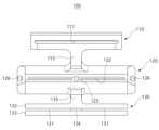
도 1은 본 발명의 일 실시예에 따른 로봇 인공관절 수술을 보완하기 위한 수술 기구의 사시도이다.
도 2는 도 1의 로봇 인공관절 수술을 보완하기 위한 수술 기구에서 챔퍼 절단 가이드와 보조 프레임이 결합된 상태를 나타낸 측면도이다.
도 3은 도 1의 로봇 인공관절 수술을 보완하기 위한 수술 기구에서 챔퍼 절단 가이드의 정면도이다.
도 4는 도 2는 도 1의 로봇 인공관절 수술을 보완하기 위한 수술 기구에서 챔퍼 절단 가이드의 배면도이다.
도 5는 도 1의 로봇 인공관절 수술을 보완하기 위한 수술 기구에서 보조 프레임의 평면도이다.
도 6은 도 1의 로봇 인공관절 수술을 보완하기 위한 수술 기구에서 보조 프레임의 저면도이다.
도 7은 본 발명에 적용되는 로봇을 이용하여 원위 대퇴골, 후방 대퇴골 및 근위 경골을 절단하는 과정을 설명하기 위한 개략적인 도면이다.
도 8 내지 도 10은 도 1의 로봇 인공관절 수술을 보완하기 위한 수술 기구를 이용하여 시술자가 로봇을 사용하지 않고 수작업으로 대퇴골을 절단하는 과정을 설명하기 위한 개략적인 도면들이다.Figure 1 is a perspective view of a surgical instrument for supplementing robotic artificial joint surgery according to an embodiment of the present invention.
Figure 2 is a side view showing a state in which a chamfer cutting guide and an auxiliary frame are combined in a surgical instrument to complement the robotic artificial joint surgery of Figure 1.
Figure 3 is a front view of a chamfer cutting guide in a surgical instrument to complement the robotic artificial joint surgery of Figure 1.
FIG. 4 is a rear view of a chamfer cutting guide in a surgical instrument for supplementing the robotic artificial joint surgery of FIG. 2 and FIG. 1 .
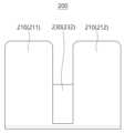
Figure 5 is a plan view of an auxiliary frame in a surgical instrument to complement the robotic artificial joint surgery of Figure 1.
Figure 6 is a bottom view of an auxiliary frame in a surgical instrument to complement the robotic artificial joint surgery of Figure 1.
Figure 7 is a schematic diagram for explaining the process of cutting the distal femur, posterior femur, and proximal tibia using a robot applied to the present invention.
FIGS. 8 to 10 are schematic diagrams illustrating a process in which a surgeon manually cuts the femur without using a robot using surgical instruments to complement the robotic artificial joint surgery of FIG. 1.
본 발명과 본 발명의 동작상의 이점 및 본 발명의 실시에 의하여 달성되는 목적을 충분히 이해하기 위해서는 본 발명의 바람직한 실시예를 예시하는 첨부 도면 및 첨부 도면에 기재된 내용을 참조하여야만 한다.In order to fully understand the present invention, its operational advantages, and the objectives achieved by practicing the present invention, reference should be made to the accompanying drawings illustrating preferred embodiments of the present invention and the contents described in the accompanying drawings.
이하, 첨부된 도면을 참조하여 본 발명의 바람직한 실시예를 설명함으로써, 본 발명을 상세히 설명한다. 다만, 본 발명을 설명함에 있어서 이미 공지된 기능 혹은 구성에 대한 설명은, 본 발명의 요지를 명료하게 하기 위하여 생략하기로 한다.Hereinafter, the present invention will be described in detail by explaining preferred embodiments of the present invention with reference to the accompanying drawings. However, in explaining the present invention, descriptions of already known functions or configurations will be omitted to make the gist of the present invention clear.
도 1은 본 발명의 일 실시예에 따른 로봇 인공관절 수술을 보완하기 위한 수술 기구의 사시도이고, 도 2는 도 1의 로봇 인공관절 수술을 보완하기 위한 수술 기구에서 챔퍼 절단 가이드와 보조 프레임이 결합된 상태를 나타낸 측면도이다.FIG. 1 is a perspective view of a surgical instrument for supplementing robotic artificial joint surgery according to an embodiment of the present invention, and FIG. 2 is a surgical instrument for supplementing robotic artificial joint surgery of FIG. 1 in which a chamfer cutting guide and an auxiliary frame are combined. This is a side view showing the condition.
그리고, 도 3 및 도 4는 도 1의 로봇 인공관절 수술을 보완하기 위한 수술 기구에서 챔퍼 절단 가이드의 정면도 및 배면도이고, 도 5 및 도 6은 도 1의 로봇 인공관절 수술을 보완하기 위한 수술 기구에서 보조 프레임의 평면도 및 저면도이다.3 and 4 are front and rear views of the chamfer cutting guide in the surgical instrument for supplementing the robotic artificial joint surgery of FIG. 1, and FIGS. 5 and 6 are front and rear views of the chamfer cutting guide for supplementing the robotic artificial joint surgery of FIG. 1. Top and bottom views of the auxiliary frame in the surgical instrument.
본 발명의 일 실시예에 따른 로봇 인공관절 수술을 보완하기 위한 수술 기구(이하 '수술 기구'라 함)는 로봇을 이용한 무릎 인공관절 전치환술을 진행함에 있어서 로봇 시스템의 도움을 받아 원위 대퇴골(distal femur), 후방 대퇴골(posterior femoral condyle) 및 근위 경골(proximal tibia)을 절단 후, 시술자(의사)가 로봇을 사용하지 않고 수작업으로 혹은 수동으로 대퇴골을 절단하는 과정에서 사용되는 수술 기구로서, 도 1 내지 도 6에 도시된 바와 같이 로봇을 이용하여 절단된 원위 대퇴골의 절제된 표면(11, 도 7 참조)에 배치되는 챔퍼 절단 가이드(100) 및 로봇을 이용하여 절단된 후방 대퇴골의 절제된 표면(12, 도 7 참조)을 기준으로 챔퍼 절단 가이드(100)의 위치를 정렬하는 보조 프레임(200)을 포함한다.A surgical instrument (hereinafter referred to as 'surgical instrument') to complement robotic artificial joint surgery according to an embodiment of the present invention is a surgical instrument that uses the help of a robotic system to remove the distal femur (distal femur) when performing total knee artificial joint replacement surgery using a robot. It is a surgical instrument used in the process of cutting the femur manually or manually without using a robot by the operator (doctor) after cutting the femur, posterior femoral condyle, and proximal tibia, Figure 1 As shown in FIGS. 6 to 6, a
도 1 내지 도 4를 참조하면, 챔퍼 절단 가이드(100)는 로봇을 이용하여 절단된 원위 대퇴골의 절제된 표면(11)에 접촉 고정된 상태로 배치된 후(도 9 참조), 전방 대퇴골(13), 전방 챔퍼(14) 및 후방 챔퍼(15)를 시술자(의사)의 수작업으로 절단하는 과정에서 톱날(미도시)의 위치 및 이동 방향을 안내하는 수단으로(도 10 참조), 상부 몸체부(110), 중앙 몸체부(120), 하부 몸체부(130) 및 고정핀(140)을 포함한다.1 to 4, the
이때, 챔퍼 절단 가이드(100)에 있어서 도 1 내지 도 4에 도시된 바와 같이 상부 몸체부(110)와 중앙 몸체부(120)가 제1 연결 몸체부(115)에 의해 연결되고, 중앙 몸체부(120)와 하부 몸체부(130)가 제2 연결 몸체부(135)에 의해 연결됨으로써, 상부 몸체부(110), 중앙 몸체부(120) 및 하부 몸체부(130)가 일체로 형성된다. 그리고, 챔퍼 절단 가이드(100)에 있어서 고정핀(140)은 도 2 및 도 4에 도시된 바와 같이 중앙 몸체부(120)의 배면에서 후방으로 돌출되도록 형성된다.At this time, in the
챔퍼 절단 가이드(100)의 상부 몸체부(110)에는 시술자가 로봇을 사용하지 않고 전방 대퇴골(13)을 절단하는 과정에서 톱날의 위치 및 이동 방향을 안내하기 위한 제1 절단 가이드홈(111)이 형성된다. 그리고, 챔퍼 절단 가이드(100)의 중앙 몸체부(120)에는 시술자가 로봇을 사용하지 않고 대퇴골의 전방 챔퍼(14)을 절단하는 과정에서 톱날의 위치 및 이동 방향을 안내하기 위한 제2 절단 가이드홈(122) 및 시술자가 로봇을 사용하지 않고 대퇴골의 후방 챔퍼(15)을 절단하는 과정에서 톱날의 위치 및 이동 방향을 안내하기 위한 제3 절단 가이드홈(123)이 각각 형성된다. 이때, 제2 절단 가이드홈(122)은 대퇴골의 전방 챔퍼(14)의 절단 각도와 대응하도록 도 2에 도시된 바와 같이 중앙 몸체부(120)에서 상향 경사진 형태로 형성되고, 제3 절단 가이드홈(123)은 대퇴골의 후방 챔퍼(15)의 절단 각도와 대응하도록 도 2에 도시된 바와 같이 중앙 몸체부(120)에서 하향 경사진 형태로 형성된다.The
즉, 챔퍼 절단 가이드(100)는 전방 대퇴골(13)을 절단하는 과정에서 톱날의 위치 및 이동 방향을 안내하는 제1 절단 가이드홈(111), 전방 챔퍼(14)를 절단하는 과정에서 톱날의 위치 및 이동 방향을 안내하는 제2 절단 가이드홈(122) 및 후방 챔퍼(15)를 절단하는 과정에서 톱날의 위치 및 이동 방향을 안내하는 제3 절단 가이드홈(123)을 포함한다.That is, the
챔퍼 절단 가이드(100)의 하부 몸체부(130)에는 후술할 보조 프레임(200)의 대퇴골 후방 접촉부(210)가 삽입되는 보조프레임 결합홈(131)이 형성된다. 이때, 보조프레임 결합홈(131)은 하부 몸체부(130)의 상하 방향으로 이격 배치된 상부 플레이트(132)와 하부 플레이트(133)의 사이 공간에 의해 형성되고, 도 3 및 도 4에 도시된 바와 같이 하부 몸체부(130)의 상부 플레이트(132)와 하부 플레이트(133)의 사이에서 하부 몸체부(130)의 중앙 영역에 형성된 격벽(134)에 의해 좌우 한 쌍으로 형성된다.The
챔퍼 절단 가이드(100)의 고정핀(140)은 챔퍼 절단 가이드(100)를 원위 대퇴골의 절제된 표면(11)에 대해 안정적으로 고정하는 수단으로, 원위 대퇴골의 절제된 표면(11)에 관통 삽입되는 방식으로 원위 대퇴골의 절제된 표면(11)에 대해 챔퍼 절단 가이드(100)를 고정한다. 즉, 챔퍼 절단 가이드(100)는 고정핀(140)을 원위 대퇴골의 절제된 표면(11)에 박아서 원위 대퇴골의 절제된 표면(11)에 대해 접촉 고정된다. 이때, 고정핀(140)을 원위 대퇴골의 절제된 표면(11)에 박는 과정에서 시술자는 소정의 타격 공구(미도시)를 사용하는데, 챔퍼 절단 가이드(100)의 중앙 몸체부(120)에는 이러한 타격 공구가 안정적으로 접촉 지지되도록 도 1 및 도 3에 도시된 바와 같이 공구 접촉홈(125)이 형성된다.The fixing
본 실시예에서 챔퍼 절단 가이드(100)의 고정핀(140)은 도 2 및 도 4에 도시된 바와 같이 챔퍼 절단 가이드(100)의 중앙 몸체부(120)의 배면에서 후방으로 돌출되도록 형성되되 좌우 한 쌍으로 제공된다. 여기서, '후방'은 원위 대퇴골의 절제된 표면(11)을 향하는 방향을 의미한다.In this embodiment, the fixing
한편, 챔퍼 절단 가이드(100)의 중앙 몸체부(120)에는 도 1 내지 도 4에 도시된 바와 같이 좌우 단부 각각에 체결공(126)이 형성되는데, 이러한 체결공(126)에는 챔퍼 절단 가이드(100)를 원위 대퇴골의 절제된 표면(11)에 대해 더욱 견고하게 고정하기 위해 별도로 제공되는 체결핀(P, 도 10 참조)이 관통하여 원위 대퇴골의 절제된 표면(11)에 체결 고정된다.Meanwhile, in the
도 1, 도 2, 도 5 및 도 6을 참조하면, 보조 프레임(200)은 챔퍼 절단 가이드(100)와 별도로 제공되며, 챔퍼 절단 가이드(100)와 결합한 상태에서 로봇을 이용하여 절단된 후방 대퇴골의 절제된 표면(12)을 기준으로 챔퍼 절단 가이드(100)의 위치를 정렬하는 수단으로(도 8 및 도 9 참조), 대퇴골 후방 접촉부(210) 및 프레임 몸체부(230)를 포함한다. 이때, 보조 프레임(200)에 있어서 대퇴골 후방 접촉부(210)과 프레임 몸체부(230)는 판금 가공 및 벤딩 가공에 의해 일체로 형성된다.Referring to FIGS. 1, 2, 5, and 6, the
보조 프레임(200)의 대퇴골 후방 접촉부(210)는 보조 프레임(200)이 챔퍼 절단 가이드(100)와 결합한 상태에서 그 상면이 후방 대퇴골의 절제된 표면(12)과 접촉하여 배치됨으로써, 챔퍼 절단 가이드(100)의 위치를 후방 대퇴골의 절제된 표면(12)을 기준으로 정렬한다.The posterior contact portion of the
이러한 대퇴골 후방 접촉부(210)는 도 1, 도 2, 도 5 및 도 6에 도시된 바와 같이 프레임 몸체부(230)에서 후방으로 연장되는 플레이트 형상으로 제공되는데, 서로 이격 배치되는 한 쌍의 핑거 플레이트(211,212)로 제공되는 것이 바람직하다. 그리고, 한 쌍의 핑거 플레이트(211,212)는 챔퍼 절단 가이드(100)의 하부 몸체부(130)에서 격벽(134)에 의해 좌우 한 쌍으로 형성되는 보조프레임 결합홈(131)에 각각 삽입된다. 이때, 한 쌍의 핑거 플레이트(211,212) 사이의 간격 부분에는 챔퍼 절단 가이드(100)에서 하부 몸체부(130)의 격벽(134)이 삽입된다.This femur
이에, 보조 프레임(200)은 한 쌍의 핑거 플레이트(211,212)로 제공되는 대퇴골 후방 접촉부(210)가 챔퍼 절단 가이드(100)의 보조프레임 결합홈(131)에 삽입되는 방식으로 챔퍼 절단 가이드(100)와 결합하게 된다.Accordingly, the
보조 프레임(200)의 프레임 몸체부(230)는 대퇴골 후방 접촉부(210)를 지지하고, 보조 프레임(200)이 챔퍼 절단 가이드(100)와 결합한 상태에서 챔퍼 절단 가이드(100)의 하부 몸체부(130)의 정면측과 저면측을 에워싸는 형상으로 제공된다.The
구체적으로, 프레임 몸체부(230)는 도 1, 도 2, 도 5 및 도 6에 도시된 바와 같이 보조 프레임(200)이 챔퍼 절단 가이드(100)와 결합한 상태에서 대퇴골 후방 접촉부(210)의 일측(정면측)에서 하측 방향으로 절곡 연장되는 제1 부분(231) 및 챔퍼 절단 가이드(100)의 보조프레임 결합홈(131)의 하측을 덮도록 제1 부분(231)에서 후방으로 절곡 연장되어 대퇴골 후방 접촉부(210)와 나란하게 배치되는 제2 부분(232)을 포함한다. 즉, 프레임 몸체부(230)는 대퇴골 후방 접촉부(210)의 일측(정면측)에서 하측 방향으로 절곡 연장된 후, 대퇴골 후방 접촉부(210)가 챔퍼 절단 가이드(100)의 보조프레임 결합홈(131)에 삽입된 상태에서 챔퍼 절단 가이드(100)의 하측을 덮도록 후방으로 절곡 연장되어 대퇴골 후방 접촉부(210)와 나란하게 배치되는 형상으로 제공된다.Specifically, the
이때, 제1 부분(231)은 보조 프레임(200)이 챔퍼 절단 가이드(100)와 결합한 상태에서 챔퍼 절단 가이드(100)의 하부 몸체부(130)의 정면측을 덮도록 배치되고, 제2 부분(232)은 보조 프레임(200)이 챔퍼 절단 가이드(100)와 결합한 상태에서 챔퍼 절단 가이드(100)의 하부 몸체부(130)의 저면측을 덮도록 배치된다.At this time, the
한편, 보조 프레임(200)은 챔퍼 절단 가이드(100)가 보조 프레임(200)과 결합한 상태에서 원위 대퇴골의 절제된 표면(11)에 배치된 후 고정핀(140)에 의해 원위 대퇴골의 절제된 표면(11)에 대해 고정되면, 챔퍼 절단 가이드(100)로부터 분리 제거 된다.Meanwhile, the
이하, 도 7 내지 도 10을 참조하여 본 발명의 일 실시예에 따른 로봇 인공관절 수술을 보완하기 위한 수술 기구를 이용하여 로봇 무릎 인공관절 전치환술을 진행하는 과정을 상세히 설명한다.Hereinafter, with reference to FIGS. 7 to 10, the process of performing robotic total knee arthroplasty using a surgical instrument to complement robotic artificial joint surgery according to an embodiment of the present invention will be described in detail.
도 7은 본 발명에 적용되는 로봇을 이용하여 원위 대퇴골, 후방 대퇴골 및 근위 경골을 절단하는 과정을 설명하기 위한 개략적인 도면이다. 그리고, 도 8 내지 도 10은 본 발명의 일 실시예에 따른 로봇을 이용한 무릎 인공관절 수술을 보완하기 위한 수술 기구을 이용하여 시술자가 로봇을 사용하지 않고 수작업으로 대퇴골을 절단하는 과정을 설명하기 위한 개략적인 도면들이다.Figure 7 is a schematic diagram for explaining the process of cutting the distal femur, posterior femur, and proximal tibia using a robot applied to the present invention. 8 to 10 are schematic illustrations of a process in which an operator manually cuts the femur without using a robot using surgical instruments to complement knee artificial joint surgery using a robot according to an embodiment of the present invention. These are drawings.
먼저, 도 7에 도시된 바와 같이 로봇을 이용하여 대퇴골(10) 및 경골(20)의 특정 부분을 절단하는 과정이 수행된다.First, as shown in FIG. 7, a process of cutting specific parts of the
구체적으로, 이 단계에서 로봇 시스템의 진동 톱날 공구는 수술 부위의 연조직을 보호하기 위해 로봇 시스템이 미리 설정한 가상의 경계 내에서 원위 대퇴골, 후방 대퇴골 및 근위 경골을 환자의 특성이나 상황에 맞게 정확하게 절단하고, 이에 따라 도 7에 도시된 바와 같이 원위 대퇴골의 절제된 표면(11), 후방 대퇴골의 절제된 표면(12) 및 근위 경골의 절제된 표면(21)을 형성한다. 이때, 진동 톱날 공구는 로봇의 암에 장착된 상태에서 로봇 시스템에 의해 제어된다.Specifically, at this stage, the oscillating saw blade tool of the robotic system accurately cuts the distal femur, posterior femur, and proximal tibia according to the patient's characteristics or situation within a virtual boundary preset by the robotic system to protect the soft tissue in the surgical area. and thus forming the
참고로, 로봇을 이용한 무릎 인공관절 전치환술에 있어서 로봇을 이용하여 대퇴골(10) 및 경골(20)의 특정 부분을 절단하는 과정을 수행하기 앞서, 수술 전 수술 계획을 위해 환자의 하지에 대해 CT 촬영을 수행하고 로봇 시스템과 통합하여 최적의 임플란트 크기, 정렬 및 위치를 식별한다. 그리고, 수술실에서 표준 내측 슬개골 주위 접근법을 사용하여 전방 및 후방 십자 인대를 제거하고 모든 무릎을 노출시킨 후, 실제 뼈 위치와 수술 중 관상 정렬을 식별하기 위해 프로브를 통해 랜드마크 보정 및 뼈 등록을 수행한다. 여기서, 수술 중 인대 및 간격 균형 조정은 무릎 굴곡, 내반/외반 및 회전을 포함한 무릎 역학을 통해 스푼이나 스프레더를 사용하여 수동으로 수행되고, 로봇 시스템에서 대칭적으로 균형과 간격을 적절하게 조정한 후, 적절한 임플란트 위치와 방향이 정의되어 시술자인 의사의 승인을 받아 로봇 시스템에 저장된다.For reference, before performing the process of cutting specific parts of the femur (10) and tibia (20) using a robot in robot-assisted total knee arthroplasty, a CT scan of the patient's lower extremities is performed for pre-surgery planning. Takes imaging and integrates with robotic systems to identify optimal implant size, alignment and location. Then, using a standard medial parapatellar approach in the operating room, remove the anterior and posterior cruciate ligaments and expose all knees, then perform landmark correction and bone registration via the probe to identify actual bone positions and intraoperative coronal alignment. do. Here, intraoperative ligament and gap balancing is performed manually using a spoon or spreader through knee mechanics including knee flexion, varus/valgus and rotation, and then symmetrically in a robotic system after appropriate balance and gap adjustments. , the appropriate implant location and direction are defined and stored in the robotic system with the approval of the surgeon.
다음으로, 도 8 및 도 9에 도시된 바와 같이 본 발명의 일 실시예에 따른 수술 기구의 보조 프레임(200)이 결합된 챔퍼 절단 가이드(100)를 원위 대퇴골의 절제된 표면(11)에 평평하게 배치한 후, 챔퍼 절단 가이드(100)를 원위 대퇴골의 절제된 표면(11)에 대해 고정하는 과정이 수행된다.Next, as shown in FIGS. 8 and 9, the
구체적으로, 이 단계에서 보조 프레임(200)은 그 대퇴골 후방 접촉부(210)가 앞서 로봇 시스템의 진동 톱날 공구에 의해 절단된 후방 대퇴골의 절제된 표면(12)과 접촉하여 배치되고, 챔퍼 절단 가이드(100)는 이러한 보조 프레임(200)과 결합한 상태로 앞서 로봇 시스템의 진동 톱날 공구에 의해 절단된 원위 대퇴골의 절제된 표면(11)과 접촉하여 배치된다. 그리고, 챔퍼 절단 가이드(100)는 이와 같이 배치된 상태에서 고정핀(140)에 의해 원위 대퇴골의 절제된 표면(11)에 대해 고정된다. 이때 시술자는 소정의 타격 공구를 챔퍼 절단 가이드(100)의 공구 접촉홈(125)에 갖다 댄 상태에서 챔퍼 절단 가이드(100)를 타격하여 고정핀(140)을 원위 대퇴골의 절제된 표면(11)에 박음으로써, 챔퍼 절단 가이드(100)를 원위 대퇴골의 절제된 표면(11)에 대해 고정할 수 있다.Specifically, at this stage the
이때, 챔퍼 절단 가이드(100)가 원위 대퇴골의 절제된 표면(11)에 대해 더욱 견고하게 고정되도록, 도 10에 도시된 바와 같이 별도로 제공되는 체결핀(P)이 사용될 수 있는데, 이러한 체결핀(P)은 중앙 몸체부(120)의 좌우 단부에 형성된 체결공(126, 도 1 내지 도 4 참조)을 관통하여 원위 대퇴골의 절제된 표면(11)에 체결 고정된다.At this time, so that the
이에 따라, 챔퍼 절단 가이드(100)는 그 자체가 원위 대퇴골의 절제된 표면(11)을 기준으로 제1 좌표 평면예컨대 Z-X 평면)상에 그 위치가 정렬되고, 보조 프레임(200)에 의해 후방 대퇴골의 절제된 표면(12)을 기준으로 제2 좌표 평면(예컨대 X-Y 평면) 및 제3 좌표 평면(예컨대 Y-Z 평면)상에 그 위치가 정렬된 상태에서 원위 대퇴골의 절제된 표면(11)에 대해 배치 고정될 수 있다.Accordingly, the
다음으로, 도 10에 도시된 바와 같이 챔퍼 절단 가이드(100)가 원위 대퇴골의 절제된 표면(11)에 고정된 상태에서 보조 프레임(200)을 챔퍼 절단 가이드(100)로부터 분리 제거한 후, 챔퍼 절단 가이드(100)를 이용하여 전방 대퇴골(13), 전방 챔퍼(14) 및 후방 챔퍼(15)를 시술자의 수작업으로 절단하는 과정이 수행된다.Next, as shown in FIG. 10, the
구체적으로, 이 단계에서 시술자는 로봇 시스템의 도움 없이 진동 톱날 공구를 파지한 상태에서, 진동 톱날 공구의 톱날을 챔퍼 절단 가이드(100)의 제1 절단 가이드홈(111)에 삽입하여 제1 절단 가이드홈(111)에 의해 안내되는 위치 및 이동 방향에 따라 전방 대퇴골(13)을 절단하고, 진동 톱날 공구의 톱날을 챔퍼 절단 가이드(100)의 제2 절단 가이드홈(122)에 삽입하여 제2 절단 가이드홈(122)에 의해 안내되는 위치 및 이동 방향에 따라 전방 챔퍼(14)을 절단하며, 진동 톱날 공구의 톱날을 챔퍼 절단 가이드(100)의 제3 절단 가이드홈(123)에 삽입하여 제3 절단 가이드홈(123)에 의해 안내되는 위치 및 이동 방향에 따라 후방 챔퍼(15)을 절단한다.Specifically, in this step, the operator holds the oscillating saw blade tool without the help of the robot system and inserts the saw blade of the oscillating saw blade tool into the first cutting
이때, 챔퍼 절단 가이드(100)는 앞서 설명한 바와 같이 로봇을 이용하여 환자의 특성이나 상황에 맞게 정확하게 절단된 원위 대퇴골의 절제된 표면(11) 및 후방 대퇴골의 절제된 표면(12)을 기준으로 그 위치가 정확하게 정렬되어 배치 고정된 상태이므로, 시술자가 전방 대퇴골(13), 전방 챔퍼(14) 및 후방 챔퍼(15)를 로봇을 사용하지 않고 수작업으로 절단하더라도, 챔퍼 절단 가이드(100)를 이용하여 전방 대퇴골(13), 전방 챔퍼(14) 및 후방 챔퍼(15)를 챔퍼 절단 가이드(100)에 의해 안내되는 미리 정해진 라인을 따라 정확하게 절단할 수 있게 된다.At this time, the
이상, 본 발명의 바람직한 실시예들을 통해 본 발명을 상세히 설명하였지만, 본 발명은 전술한 바람직한 실시예들에 한정되는 것이 아니고, 본 발명의 사상 및 범위를 벗어나지 않고 다양하게 수정 및 변형할 수 있음은 이 기술 분야에서 통상의 지식을 가진 자에게 자명하다. 따라서 그러한 수정예 또는 변형예들은 본 발명의 청구범위에 속한다 하여야 할 것이다.Although the present invention has been described in detail through preferred embodiments of the present invention, the present invention is not limited to the above-described preferred embodiments, and various modifications and variations can be made without departing from the spirit and scope of the present invention. It is obvious to those skilled in the art. Accordingly, such modifications or variations should be considered to fall within the scope of the claims of the present invention.
100: 챔퍼 절단 가이드
110: 상부 몸체부
120: 중앙 몸체부
130: 하부 몸체부
140: 고정핀
111: 제1 절단 가이드홈
122: 제2 절단 가이드홈
123: 제3 절단 가이드홈
131: 보조프레임 결합홈
200: 보조 프레임
210: 대퇴골 후방 접촉부
230: 프레임 몸체부100: Chamfer cutting guide
110: upper body part
120: central body portion
130: lower body part
140: fixing pin
111: First cutting guide groove
122: Second cutting guide groove
123: Third cutting guide groove
131: Auxiliary frame coupling groove
200: Secondary frame
210: Femur posterior contact area
230: Frame body part
Claims (8)
Translated fromKorean상기 로봇을 이용하여 절단된 후방 대퇴골의 절제된 표면을 기준으로 상기 챔퍼 절단 가이드의 위치를 정렬하기 위해 상기 챔퍼 절단 가이드와 결합하는 보조 프레임
을 포함하며,
상기 원위 대퇴골의 절제된 표면 및 상기 후방 대퇴골의 절제된 표면은 상기 로봇의 암에 장착되고 상기 로봇의 시스템에 의해 제어되는 진동 톱날 공구가 상기 로봇의 시스템에 의해 미리 설정된 가상의 경계 내에서 상기 원위 대퇴골 및 상기 후방 대퇴골을 절단하여 형성되고,
상기 챔퍼 절단 가이드는 상기 원위 대퇴골의 절제된 표면과 접촉하여 배치되는 것에 의해 상기 원위 대퇴골의 절제된 표면을 기준으로 그 위치가 정렬되고, 상기 보조 프레임에 의해 상기 후방 대퇴골의 절제된 표면을 기준으로 그 위치가 정렬되며,
상기 보조 프레임은 후방으로 연장되는 플레이트 형상으로 마련되고 상기 챔퍼 절단 가이드와 결합한 상태에서 상기 후방 대퇴골의 절제된 표면과 접촉하여 배치되는 대퇴골 후방 접촉부, 및 상기 대퇴골 후방 접촉부를 지지하는 프레임 몸체부를 포함하고,
상기 보조 프레임은 상기 대퇴골 후방 접촉부가 상기 챔퍼 절단 가이드에 형성된 보조프레임 결합홈에 삽입되는 방식으로 상기 챔퍼 절단 가이드와 결합하며,
상기 대퇴골 후방 접촉부는 상기 보조프레임 결합홈에 삽입된 상태에서 그 상면이 상기 후방 대퇴골의 절제된 표면과 접촉하여 배치되고,
상기 프레임 몸체부는 상기 보조 프레임이 상기 챔퍼 절단 가이드와 결합한 상태에서, 상기 대퇴골 후방 접촉부의 일측에서 하측 방향으로 절곡 연장되는 제1 부분, 및 상기 보조프레임 결합홈의 하측을 덮도록 상기 제1 부분에서 후방으로 절곡 연장되어 상기 대퇴골 후방 접촉부와 나란하게 배치되는 제2 부분을 포함하는 것을 특징으로 하는 로봇 인공관절 수술을 보완하기 위한 수술 기구.
A chamfer cutting guide placed on the resected surface of the distal femur cut using a robot and guiding the position and moving direction of the saw blade during the operator's manual cutting of the anterior femur, anterior chamfer, and posterior chamfer; and
An auxiliary frame coupled with the chamfer cutting guide to align the position of the chamfer cutting guide with respect to the excised surface of the posterior femur cut using the robot.
Includes,
The ablated surface of the distal femur and the ablated surface of the posterior femur are mounted on an arm of the robot and an oscillating saw blade tool controlled by the system of the robot is positioned between the distal femur and the ablated surface within virtual boundaries preset by the system of the robot. Formed by cutting the posterior femur,
The chamfer cutting guide is positioned in contact with the ablated surface of the distal femur, thereby aligning its position relative to the ablated surface of the distal femur, and having its position relative to the ablated surface of the posterior femur by the auxiliary frame. sorted,
The auxiliary frame is provided in the shape of a plate extending rearward and includes a femur rear contact portion disposed in contact with the excised surface of the posterior femur in a state engaged with the chamfer cutting guide, and a frame body portion supporting the femur rear contact portion,
The auxiliary frame is coupled to the chamfer cutting guide in such a way that the posterior contact portion of the femur is inserted into the auxiliary frame coupling groove formed in the chamfer cutting guide,
The femur rear contact portion is inserted into the auxiliary frame coupling groove and its upper surface is disposed in contact with the excised surface of the rear femur,
When the auxiliary frame is coupled to the chamfer cutting guide, the frame body portion includes a first part bent and extending downward from one side of the femur rear contact portion, and a lower side of the auxiliary frame coupling groove to cover the first part. A surgical instrument for supplementing robotic artificial joint surgery, comprising a second portion bent and extended backward and disposed in parallel with the posterior contact portion of the femur.
상기 챔퍼 절단 가이드는
상기 전방 대퇴골을 절단하는 과정에서 상기 톱날의 위치 및 이동 방향을 안내하는 제1 절단 가이드홈;
상기 전방 챔퍼를 절단하는 과정에서 상기 톱날의 위치 및 이동 방향을 안내하는 제2 절단 가이드홈; 및
상기 후방 챔퍼를 절단하는 과정에서 상기 톱날의 위치 및 이동 방향을 안내하는 제3 절단 가이드홈
을 포함하는 것을 특징으로 하는 로봇 인공관절 수술을 보완하기 위한 수술 기구.
According to paragraph 1,
The chamfer cutting guide is
a first cutting guide groove that guides the position and movement direction of the saw blade in the process of cutting the anterior femur;
a second cutting guide groove that guides the position and movement direction of the saw blade in the process of cutting the front chamfer; and
A third cutting guide groove that guides the position and movement direction of the saw blade in the process of cutting the rear chamfer.
A surgical instrument to complement robotic artificial joint surgery, comprising:
상기 챔퍼 절단 가이드는
상기 원위 대퇴골의 절제된 표면에 대해 안정적으로 고정되도록 상기 원위 대퇴골의 절제된 표면에 삽입되는 고정핀
을 더 포함하는 것을 특징으로 하는 로봇 인공관절 수술을 보완하기 위한 수술 기구.
In paragraph 2
The chamfer cutting guide is
A fixation pin inserted into the resected surface of the distal femur to secure it stably against the resected surface of the distal femur.
A surgical instrument to complement robotic artificial joint surgery, further comprising:
상기 대퇴골 후방 접촉부는
서로 이격 배치되는 한 쌍의 핑거 플레이트로 제공되는 것을 특징으로 하는 로봇 인공관절 수술을 보완하기 위한 수술 기구.
In paragraph 1
The posterior contact portion of the femur is
A surgical instrument to complement robotic artificial joint surgery, characterized in that it is provided as a pair of finger plates spaced apart from each other.
상기 보조프레임 결합홈은 중앙 영역에 형성된 격벽에 의해 한 쌍의 보조프레임 결합홈으로 제공되며,
상기 한 쌍의 핑거 플레이트는 상기 한 쌍의 보조프레임 결합홈에 각각 삽입되는 것을 특징으로 하는 로봇 인공관절 수술을 보완하기 위한 수술 기구.In paragraph 6
The auxiliary frame coupling groove is provided as a pair of auxiliary frame coupling grooves by a partition formed in the central area,
A surgical instrument for supplementing robotic artificial joint surgery, wherein the pair of finger plates are respectively inserted into the pair of auxiliary frame coupling grooves.
Priority Applications (2)
| Application Number | Priority Date | Filing Date | Title |
|---|---|---|---|
| KR1020230166358AKR102652930B1 (en) | 2023-11-27 | 2023-11-27 | Surgical instrument to complement robotic artificial joint surgery |
| PCT/KR2023/019659WO2025116090A1 (en) | 2023-11-27 | 2023-12-01 | Surgical instrument for complementing robotic artificial joint surgery |
Applications Claiming Priority (1)
| Application Number | Priority Date | Filing Date | Title |
|---|---|---|---|
| KR1020230166358AKR102652930B1 (en) | 2023-11-27 | 2023-11-27 | Surgical instrument to complement robotic artificial joint surgery |
Publications (1)
| Publication Number | Publication Date |
|---|---|
| KR102652930B1true KR102652930B1 (en) | 2024-03-28 |
Family
ID=90482565
Family Applications (1)
| Application Number | Title | Priority Date | Filing Date |
|---|---|---|---|
| KR1020230166358AActiveKR102652930B1 (en) | 2023-11-27 | 2023-11-27 | Surgical instrument to complement robotic artificial joint surgery |
Country Status (2)
| Country | Link |
|---|---|
| KR (1) | KR102652930B1 (en) |
| WO (1) | WO2025116090A1 (en) |
Citations (5)
| Publication number | Priority date | Publication date | Assignee | Title |
|---|---|---|---|---|
| KR19980702248A (en)* | 1995-02-15 | 1998-07-15 | 존 데이비드 홉스 | Distal Femoral Cut Guide |
| KR100566767B1 (en) | 2004-04-27 | 2006-03-31 | 서재곤 | Alignment linkage device for linking femoral fracture and tibial fracture in artificial knee replacement surgery. |
| KR101043048B1 (en) | 2009-02-13 | 2011-06-21 | 서경석 | Set of instruments for arthroplasty |
| KR101073871B1 (en) | 2009-12-14 | 2011-10-14 | 서경석 | Instrument set for atrificial knee joint operation |
| KR102186308B1 (en) | 2019-01-28 | 2020-12-03 | 주식회사 코렌텍 | Smart surgical instruments for artificial joint replacement |
Family Cites Families (3)
| Publication number | Priority date | Publication date | Assignee | Title |
|---|---|---|---|---|
| IT1235428B (en)* | 1988-04-29 | 1992-07-10 | Cremascoli Spa G | INSTRUMENTAL DEVICE, SUITABLE FOR ALLOWING A CORRECT FEMORAL RESECTION, FOR THE APPLICATION OF REPLACEMENT PROSTHESES OF THE KNEE ARTICULATION. |
| GB9202561D0 (en)* | 1992-02-07 | 1992-03-25 | Howmedica | Orthopaedic instrument |
| EP2561814A1 (en)* | 2011-08-25 | 2013-02-27 | Deru GmbH | Cutting guide for creating an external contour for an articulated endoprosthetic |
- 2023
- 2023-11-27KRKR1020230166358Apatent/KR102652930B1/enactiveActive
- 2023-12-01WOPCT/KR2023/019659patent/WO2025116090A1/enactivePending
Patent Citations (5)
| Publication number | Priority date | Publication date | Assignee | Title |
|---|---|---|---|---|
| KR19980702248A (en)* | 1995-02-15 | 1998-07-15 | 존 데이비드 홉스 | Distal Femoral Cut Guide |
| KR100566767B1 (en) | 2004-04-27 | 2006-03-31 | 서재곤 | Alignment linkage device for linking femoral fracture and tibial fracture in artificial knee replacement surgery. |
| KR101043048B1 (en) | 2009-02-13 | 2011-06-21 | 서경석 | Set of instruments for arthroplasty |
| KR101073871B1 (en) | 2009-12-14 | 2011-10-14 | 서경석 | Instrument set for atrificial knee joint operation |
| KR102186308B1 (en) | 2019-01-28 | 2020-12-03 | 주식회사 코렌텍 | Smart surgical instruments for artificial joint replacement |
Also Published As
| Publication number | Publication date |
|---|---|
| WO2025116090A1 (en) | 2025-06-05 |
Similar Documents
| Publication | Publication Date | Title |
|---|---|---|
| US12274452B2 (en) | Surgical kit for tibial resection and replacement | |
| JP6147780B2 (en) | Method and apparatus for performing knee arthroplasty | |
| EP0121780B1 (en) | Apparatus for shaping a distal femoral surface | |
| JP3921635B2 (en) | Cutting guide for cutting knee joints | |
| US9861387B2 (en) | Patient-specific knee alignment guide and associated method | |
| EP2407115B1 (en) | Instrumentation for use in a patellofemoral arthroplasty procedure | |
| CA2489522C (en) | Knee computer-aided navigation instruments | |
| EP1631192B1 (en) | Robotic total/partial knee arthoplastics | |
| US20030018338A1 (en) | Methods and tools for femoral resection in primary knee surgery | |
| US20050234465A1 (en) | Guided saw with pins | |
| US20060271056A1 (en) | System and method for modular navigated osteotome | |
| US20140364857A1 (en) | Joint Arthroplasty Devices, Systems, and Methods | |
| JPS6329546B2 (en) | ||
| CN101610731A (en) | Computer-assisted surgical method and system for bicompartmental knee replacement | |
| EP0971638A4 (en) | METHOD AND APPARATUS FOR RESECTING FEMUR | |
| WO1998032384A9 (en) | Method and apparatus for femoral resection | |
| JP2020018382A (en) | Laser projection appliance and guide appliance | |
| KR102652930B1 (en) | Surgical instrument to complement robotic artificial joint surgery | |
| JP2019098050A (en) | Patient suitable type guide installation appliance | |
| US20240099858A1 (en) | Gap balancing assembly for knee revision surgery | |
| US11553928B2 (en) | Tibial cutting guide assemblies and associated instrumentation for performing surgical methods | |
| Scuderi | Instrumentation for unicondylar knee replacement | |
| JP2020096761A (en) | Guide system for supporting artificial joint installation surgery, and instrument for the same | |
| US20060241638A1 (en) | Anatomical landmark guide |
Legal Events
| Date | Code | Title | Description |
|---|---|---|---|
| PA0109 | Patent application | Patent event code:PA01091R01D Comment text:Patent Application Patent event date:20231127 | |
| PA0201 | Request for examination | ||
| PA0302 | Request for accelerated examination | Patent event date:20231128 Patent event code:PA03022R01D Comment text:Request for Accelerated Examination Patent event date:20231127 Patent event code:PA03021R01I Comment text:Patent Application | |
| PE0902 | Notice of grounds for rejection | Comment text:Notification of reason for refusal Patent event date:20231219 Patent event code:PE09021S01D | |
| E701 | Decision to grant or registration of patent right | ||
| PE0701 | Decision of registration | Patent event code:PE07011S01D Comment text:Decision to Grant Registration Patent event date:20240325 | |
| GRNT | Written decision to grant | ||
| PR0701 | Registration of establishment | Comment text:Registration of Establishment Patent event date:20240326 Patent event code:PR07011E01D | |
| PR1002 | Payment of registration fee | Payment date:20240326 End annual number:3 Start annual number:1 | |
| PG1601 | Publication of registration |