KR102650633B1 - Display device - Google Patents
Display deviceDownload PDFInfo
- Publication number
- KR102650633B1 KR102650633B1KR1020180142473AKR20180142473AKR102650633B1KR 102650633 B1KR102650633 B1KR 102650633B1KR 1020180142473 AKR1020180142473 AKR 1020180142473AKR 20180142473 AKR20180142473 AKR 20180142473AKR 102650633 B1KR102650633 B1KR 102650633B1
- Authority
- KR
- South Korea
- Prior art keywords
- hinge
- pair
- folding
- panel
- frame
- Prior art date
- Legal status (The legal status is an assumption and is not a legal conclusion. Google has not performed a legal analysis and makes no representation as to the accuracy of the status listed.)
- Active
Links
Images

Classifications
- G—PHYSICS
- G09—EDUCATION; CRYPTOGRAPHY; DISPLAY; ADVERTISING; SEALS
- G09F—DISPLAYING; ADVERTISING; SIGNS; LABELS OR NAME-PLATES; SEALS
- G09F9/00—Indicating arrangements for variable information in which the information is built-up on a support by selection or combination of individual elements
- G09F9/30—Indicating arrangements for variable information in which the information is built-up on a support by selection or combination of individual elements in which the desired character or characters are formed by combining individual elements
- G09F9/301—Indicating arrangements for variable information in which the information is built-up on a support by selection or combination of individual elements in which the desired character or characters are formed by combining individual elements flexible foldable or roll-able electronic displays, e.g. thin LCD, OLED
- G—PHYSICS
- G06—COMPUTING OR CALCULATING; COUNTING
- G06F—ELECTRIC DIGITAL DATA PROCESSING
- G06F1/00—Details not covered by groups G06F3/00 - G06F13/00 and G06F21/00
- G06F1/16—Constructional details or arrangements
- G06F1/1613—Constructional details or arrangements for portable computers
- G06F1/1615—Constructional details or arrangements for portable computers with several enclosures having relative motions, each enclosure supporting at least one I/O or computing function
- G06F1/1616—Constructional details or arrangements for portable computers with several enclosures having relative motions, each enclosure supporting at least one I/O or computing function with folding flat displays, e.g. laptop computers or notebooks having a clamshell configuration, with body parts pivoting to an open position around an axis parallel to the plane they define in closed position
- G06F1/1618—Constructional details or arrangements for portable computers with several enclosures having relative motions, each enclosure supporting at least one I/O or computing function with folding flat displays, e.g. laptop computers or notebooks having a clamshell configuration, with body parts pivoting to an open position around an axis parallel to the plane they define in closed position the display being foldable up to the back of the other housing with a single degree of freedom, e.g. by 360° rotation over the axis defined by the rear edge of the base enclosure
- F—MECHANICAL ENGINEERING; LIGHTING; HEATING; WEAPONS; BLASTING
- F16—ENGINEERING ELEMENTS AND UNITS; GENERAL MEASURES FOR PRODUCING AND MAINTAINING EFFECTIVE FUNCTIONING OF MACHINES OR INSTALLATIONS; THERMAL INSULATION IN GENERAL
- F16C—SHAFTS; FLEXIBLE SHAFTS; ELEMENTS OR CRANKSHAFT MECHANISMS; ROTARY BODIES OTHER THAN GEARING ELEMENTS; BEARINGS
- F16C11/00—Pivots; Pivotal connections
- F16C11/04—Pivotal connections
- G—PHYSICS
- G06—COMPUTING OR CALCULATING; COUNTING
- G06F—ELECTRIC DIGITAL DATA PROCESSING
- G06F1/00—Details not covered by groups G06F3/00 - G06F13/00 and G06F21/00
- G06F1/16—Constructional details or arrangements
- G06F1/1613—Constructional details or arrangements for portable computers
- G06F1/1615—Constructional details or arrangements for portable computers with several enclosures having relative motions, each enclosure supporting at least one I/O or computing function
- G06F1/1616—Constructional details or arrangements for portable computers with several enclosures having relative motions, each enclosure supporting at least one I/O or computing function with folding flat displays, e.g. laptop computers or notebooks having a clamshell configuration, with body parts pivoting to an open position around an axis parallel to the plane they define in closed position
- G—PHYSICS
- G06—COMPUTING OR CALCULATING; COUNTING
- G06F—ELECTRIC DIGITAL DATA PROCESSING
- G06F1/00—Details not covered by groups G06F3/00 - G06F13/00 and G06F21/00
- G06F1/16—Constructional details or arrangements
- G06F1/1613—Constructional details or arrangements for portable computers
- G06F1/1633—Constructional details or arrangements of portable computers not specific to the type of enclosures covered by groups G06F1/1615 - G06F1/1626
- G06F1/1637—Details related to the display arrangement, including those related to the mounting of the display in the housing
- G06F1/1641—Details related to the display arrangement, including those related to the mounting of the display in the housing the display being formed by a plurality of foldable display components
- G—PHYSICS
- G06—COMPUTING OR CALCULATING; COUNTING
- G06F—ELECTRIC DIGITAL DATA PROCESSING
- G06F1/00—Details not covered by groups G06F3/00 - G06F13/00 and G06F21/00
- G06F1/16—Constructional details or arrangements
- G06F1/1613—Constructional details or arrangements for portable computers
- G06F1/1633—Constructional details or arrangements of portable computers not specific to the type of enclosures covered by groups G06F1/1615 - G06F1/1626
- G06F1/1637—Details related to the display arrangement, including those related to the mounting of the display in the housing
- G06F1/1652—Details related to the display arrangement, including those related to the mounting of the display in the housing the display being flexible, e.g. mimicking a sheet of paper, or rollable
- G—PHYSICS
- G06—COMPUTING OR CALCULATING; COUNTING
- G06F—ELECTRIC DIGITAL DATA PROCESSING
- G06F1/00—Details not covered by groups G06F3/00 - G06F13/00 and G06F21/00
- G06F1/16—Constructional details or arrangements
- G06F1/1613—Constructional details or arrangements for portable computers
- G06F1/1633—Constructional details or arrangements of portable computers not specific to the type of enclosures covered by groups G06F1/1615 - G06F1/1626
- G06F1/1675—Miscellaneous details related to the relative movement between the different enclosures or enclosure parts
- G06F1/1681—Details related solely to hinges
- H—ELECTRICITY
- H04—ELECTRIC COMMUNICATION TECHNIQUE
- H04M—TELEPHONIC COMMUNICATION
- H04M1/00—Substation equipment, e.g. for use by subscribers
- H04M1/02—Constructional features of telephone sets
- H04M1/0202—Portable telephone sets, e.g. cordless phones, mobile phones or bar type handsets
- H04M1/0206—Portable telephones comprising a plurality of mechanically joined movable body parts, e.g. hinged housings
- H04M1/0208—Portable telephones comprising a plurality of mechanically joined movable body parts, e.g. hinged housings characterized by the relative motions of the body parts
- H04M1/0214—Foldable telephones, i.e. with body parts pivoting to an open position around an axis parallel to the plane they define in closed position
- H04M1/0216—Foldable in one direction, i.e. using a one degree of freedom hinge
- H04M1/022—The hinge comprising two parallel pivoting axes
- H—ELECTRICITY
- H04—ELECTRIC COMMUNICATION TECHNIQUE
- H04M—TELEPHONIC COMMUNICATION
- H04M1/00—Substation equipment, e.g. for use by subscribers
- H04M1/02—Constructional features of telephone sets
- H04M1/0202—Portable telephone sets, e.g. cordless phones, mobile phones or bar type handsets
- H04M1/026—Details of the structure or mounting of specific components
- H04M1/0266—Details of the structure or mounting of specific components for a display module assembly
- H04M1/0268—Details of the structure or mounting of specific components for a display module assembly including a flexible display panel
- H—ELECTRICITY
- H05—ELECTRIC TECHNIQUES NOT OTHERWISE PROVIDED FOR
- H05K—PRINTED CIRCUITS; CASINGS OR CONSTRUCTIONAL DETAILS OF ELECTRIC APPARATUS; MANUFACTURE OF ASSEMBLAGES OF ELECTRICAL COMPONENTS
- H05K5/00—Casings, cabinets or drawers for electric apparatus
- H05K5/02—Details
- H05K5/0217—Mechanical details of casings
- H05K5/0226—Hinges
- E—FIXED CONSTRUCTIONS
- E05—LOCKS; KEYS; WINDOW OR DOOR FITTINGS; SAFES
- E05D—HINGES OR SUSPENSION DEVICES FOR DOORS, WINDOWS OR WINGS
- E05D3/00—Hinges with pins
- E05D3/06—Hinges with pins with two or more pins
- E—FIXED CONSTRUCTIONS
- E05—LOCKS; KEYS; WINDOW OR DOOR FITTINGS; SAFES
- E05D—HINGES OR SUSPENSION DEVICES FOR DOORS, WINDOWS OR WINGS
- E05D7/00—Hinges or pivots of special construction
- E—FIXED CONSTRUCTIONS
- E05—LOCKS; KEYS; WINDOW OR DOOR FITTINGS; SAFES
- E05Y—INDEXING SCHEME ASSOCIATED WITH SUBCLASSES E05D AND E05F, RELATING TO CONSTRUCTION ELEMENTS, ELECTRIC CONTROL, POWER SUPPLY, POWER SIGNAL OR TRANSMISSION, USER INTERFACES, MOUNTING OR COUPLING, DETAILS, ACCESSORIES, AUXILIARY OPERATIONS NOT OTHERWISE PROVIDED FOR, APPLICATION THEREOF
- E05Y2999/00—Subject-matter not otherwise provided for in this subclass
Landscapes
- Engineering & Computer Science (AREA)
- Theoretical Computer Science (AREA)
- Physics & Mathematics (AREA)
- Computer Hardware Design (AREA)
- General Physics & Mathematics (AREA)
- General Engineering & Computer Science (AREA)
- Human Computer Interaction (AREA)
- Signal Processing (AREA)
- Mathematical Physics (AREA)
- Microelectronics & Electronic Packaging (AREA)
- Mechanical Engineering (AREA)
- Devices For Indicating Variable Information By Combining Individual Elements (AREA)
Abstract
Translated fromKoreanDescription
Translated fromKorean본 발명은 디스플레이 장치에 관한 것으로, 보다 상세하게는 폴더블 디스플레이 장치(Foldable Display device)에 관한 것이다.The present invention relates to a display device, and more specifically to a foldable display device.
최근의 정보화 사회에서 디스플레이 장치(Display Device) 또는 표시장치는 시각정보 전달매체로서 그 중요성이 한층 강조되고 있으며, 향후 주요한 위치를 점하기 위해서는 저소비전력화, 박형화, 경량화, 고화질화 등의 요건을 충족시켜야 한다.In the recent information society, the importance of display devices as visual information delivery media is being further emphasized, and in order to occupy a major position in the future, they must meet requirements such as low power consumption, thinness, weight reduction, and high image quality. .
디스플레이는 자체가 빛을 내는 브라운관(Cathode Ray Tube; CRT), 전계발광소자(Electro Luminescence; EL), 발광소자(Light Emitting Diode; LED), 진공형광표시장치(Vacuum Fluorescent Display; VFD), 전계방출 디스플레이(Field Emission Display; FED), 플라즈마 디스플레이패널(Plasma Display Panel; PDP), 유기발광소자(Organic Light Emitting Diodes : OLED) 등의 발광형과, 액정 표시장치(Liquid Crystal Display; LCD)와 같이 자체가 빛을 내지 못하는 비발광형으로 나눌 수 있다.Displays include cathode ray tubes (CRT), electro luminescence (EL), light emitting diodes (LED), vacuum fluorescent displays (VFD), and electric field emission that emit light. Light-emitting displays such as Field Emission Display (FED), Plasma Display Panel (PDP), Organic Light Emitting Diodes (OLED), and self-emitting devices such as Liquid Crystal Display (LCD) It can be divided into non-luminous types that do not emit light.
한편, 기술의 진보에 따라 기존의 디스플레이에 적용되던 유연성이 없는 유리기판 대신에 플라스틱 등과 같이 유연성 있는 재료를 사용하여 종이처럼 휘어져도 표시 성능을 그대로 유지할 수 있게 제조된 플렉서블(flexible) 디스플레이 장치가 차세대 디스플레이 장치로 급부상중이다.Meanwhile, with the advancement of technology, the next generation of flexible display devices, which are manufactured using flexible materials such as plastic instead of the inflexible glass substrate used in existing displays and can maintain display performance even when bent like paper, is becoming the next generation. It is rapidly emerging as a display device.
플렉서블 디스플레이 장치는 유리가 아닌 플라스틱 박막트랜지스터 기판을 활용하여 내구성이 높은 언브레이커블(unbreakable), 깨지지 않으면서도 구부릴 수 있는 밴더블(bendable), 둘둘 말 수 있는 롤러블(rollable), 접을 수 있는 폴더블(foldable) 등으로 구분될 수 있다. 이러한 플렉서블 디스플레이 장치는 공간활용성, 인테리어 및 디자인의 장점을 가지며, 다양한 응용분야를 가질 수 있다.Flexible display devices utilize plastic thin-film transistor substrates rather than glass and can be used as highly durable unbreakable devices, bendable devices that can be bent without breaking, rollable devices that can be rolled up, and foldable folder devices. It can be classified as foldable, etc. These flexible display devices have advantages in space utilization, interior design, and design, and can have various application fields.
특히, 최근에는 초박형, 경량화 및 소형화와 함께 대면적화를 구현하기 위해, 접힌 상태로 휴대가 가능하고 펼쳐진 상태에서 영상을 표시하는 폴더블 디스플레이 장치에 대한 연구가 활발히 진행되고 있다.In particular, research has been actively conducted recently on foldable display devices that are portable in a folded state and display images in an unfolded state in order to realize ultra-thinness, lightness, and miniaturization as well as large area.
폴더블 디스플레이 장치는 모바일폰, 울트라 모바일 피씨(ultra mobile PC), 전자책, 전자신문과 같은 모바일 장치뿐만 아니라, TV, 모니터 등 다양한 분야에 응용될 수 있다.Foldable display devices can be applied to various fields such as TVs and monitors, as well as mobile devices such as mobile phones, ultra mobile PCs, e-books, and electronic newspapers.
폴더블 디스플레이 장치는 접힘(Folding)과 펼침(Un-Folding)을 가능하게 하도록 힌지(Hinge) 기구물을 구비한다.The foldable display device is equipped with a hinge mechanism to enable folding and unfolding.
여기서 일반적으로 사용되는 힌지 기구물은 체인(Chain)을 포함하는 다양한 구조의 링크결합(Multi-Link Hinge)을 이용하거나, 2개의 힌지축을 포함하는 중심체로 연결된 폴딩 구조(2-Axis Folding Hinge)로 구현된다.The hinge mechanism commonly used here uses a multi-link hinge of various structures including a chain, or is implemented as a folding structure (2-Axis Folding Hinge) connected by a central body including two hinge axes. do.
그런데 이러한 힌지 기구물은 폴딩 구간이 완전히 닫히지 않아서 외부 하중에 대한 내구성이 취약해지거나, 폴딩 상태에서 패널이 휠 수 있는 내부 공간을 확보하기 위하여 베젤(Bezel)의 폭이 커지는 문제를 야기할 수 있다.However, such a hinge mechanism may cause problems such as the durability against external loads becoming weak because the folding section is not completely closed, or the width of the bezel being increased to secure an internal space where the panel can bend in the folded state.
따라서 본 발명은 원활한 폴딩이 이루어지면서도 폴딩 구간이 완전히 닫히는 견고한 구조를 제공함으로써 외부 하중에 의한 충분한 내구성을 확보할 수 있고, 패널이 휠 수 있는 충분한 공간 확보가 가능하므로 베젤의 폭을 축소시킬 수 있는 디스플레이 장치를 제공하고자 한다.Therefore, the present invention provides a sturdy structure that allows smooth folding and completely closes the folding section, thereby ensuring sufficient durability against external loads and securing sufficient space for the panel to bend, making it possible to reduce the width of the bezel. We would like to provide a display device that has
이와 같은 과제를 해결하기 위하여, 본 발명은 서로 인접하는 제1 및 제2 프레임과, 상기 제1 및 제2 프레임 내측에 배치되는 패널과, 및 상기 제1 프레임과 상기 제2 프레임의 폴딩을 가능하게 하며, 상기 제1 및 제2 프레임에 결합되는 폴딩 힌지부를 포함하며, 상기 폴딩 힌지부는, 상기 패널의 위치가 변화되도록 상기 패널을 지지하며, 서로 이격되는 한 쌍의 패널지지판과, 상기 한 쌍의 패널지지판 아래에 각각 배치되고, 폴딩 중심축을 중심으로 이동가능하게 결합되는 제1 및 제2 힌지링크과, 상기 한 쌍의 패널지지판와 상기 제1 및 제2 힌지링크를 이동 가능하게 지지하며 상기 제1 프레임과 상기 제2 프레임에 각각 결합되는 한 쌍의 힌지 브라켓을 포함하는 디스플레이 장치를 제공한다.In order to solve this problem, the present invention enables first and second frames adjacent to each other, a panel disposed inside the first and second frames, and folding of the first frame and the second frame. and includes a folding hinge portion coupled to the first and second frames, the folding hinge portion supporting the panel so that the position of the panel is changed, a pair of panel support plates spaced apart from each other, and the pair of panel support plates. first and second hinge links respectively disposed below the panel support plate and movably coupled about the folding central axis, movably supporting the pair of panel support plates and the first and second hinge links, and movably supporting the first and second hinge links. A display device is provided including a frame and a pair of hinge brackets respectively coupled to the second frame.
상기 패널지지판은 길이 방향의 양 측면에 형성된 핀삽입홀을 포함하며, 상기 폴딩 힌지부는 상기 핀삽입홀에 각각 삽입되어 상기 힌지 브라켓에 상기 패널지지판를 이동가능하게 결합시키는 지지판 회전핀을 더 포함할 수 있다.The panel support plate includes pin insertion holes formed on both sides in the longitudinal direction, and the folding hinge portion may further include a support plate rotation pin that is inserted into each of the pin insertion holes and movably couples the panel support plate to the hinge bracket. there is.
상기 핀삽입홀은 상기 패널지지판이 편심 회전하도록 상기 패널지지판의 일측 가장자리 영역에 위치할 수 있다.The pin insertion hole may be located at one edge of the panel support plate so that the panel support plate rotates eccentrically.
상기 힌지 브라켓은 상기 지지판 회전핀이 삽입되는 회전핀 장착홀을 포함할 수 있다.The hinge bracket may include a rotation pin mounting hole into which the support plate rotation pin is inserted.
상기 제1 힌지링크는 세로 방향으로 긴 바 형상을 갖는 세로부재 및 상기 세로부재의 양측 단부에서 가로 방향으로 각각 연장된 한 쌍의 가로부재를 포함할 수 있다.The first hinge link may include a vertical member having a long bar shape in the vertical direction and a pair of horizontal members each extending in the horizontal direction from both ends of the vertical member.
상기 제1 힌지링크는 상기 세로부재의 양 단부에 돌출된 한 쌍의 제1 슬롯핀과, 상기 가로부재에 각각 형성되는 한 쌍의 제1 연결핀 삽입홀과, 및 상기 가로부재의 단부에 각각 위치하는 한 쌍의 제1 힌지축 삽입홀 을 포함할 수 있다.The first hinge link includes a pair of first slot pins protruding from both ends of the vertical member, a pair of first connection pin insertion holes respectively formed in the horizontal member, and a pair of first connection pin insertion holes respectively formed at the ends of the horizontal member. It may include a pair of first hinge shaft insertion holes positioned.
상기 제1 힌지링크는 상기 세로부재의 길이 방향을 따라 구비되며, 경사진 형상을 갖는 제1 슬라이딩 돌기를 더 포함할 수 있다.The first hinge link is provided along the longitudinal direction of the vertical member and may further include a first sliding protrusion having an inclined shape.
상기 제2 힌지링크는 세로 방향으로 긴 플레이트 형상을 가질 수 있다.The second hinge link may have a plate shape that is long in the vertical direction.
상기 제2 힌지링크는 측면부 외측의 양 단부에 돌출된 한 쌍의 제2 슬롯핀과, 측면부에 각각 형성되며 상기 한 쌍의 제1 연결핀 삽입홀과 각각 연통되는 한 쌍의 제2 연결핀 삽입홀과, 측면부 내측의 양 단부에 각각 위치하는 한 쌍의 제2 힌지축 삽입홀을 포함할 수 있다.The second hinge link includes a pair of second slot pins protruding from both ends outside the side portion, and a pair of second connection pin inserts formed on the side portion and each communicating with the pair of first connection pin insertion holes. It may include a hole and a pair of second hinge shaft insertion holes respectively located at both ends inside the side portion.
상기 제2 힌지링크는 길이 방향을 따라 구비되며, 경사진 형상을 갖는 제2 슬라이딩 돌기를 더 포함할 수 있다.The second hinge link is provided along the longitudinal direction and may further include a second sliding protrusion having an inclined shape.
상기 폴딩 힌지부는 상기 제1 및 제2 연결핀 삽입홀에 삽입되며 상기 폴딩 중심축을 이루며, 상기 제1 및 제2 힌지링크를 회전 가능하게 결합시키는 한 쌍의 링크 연결핀을 더 포함할 수 있다.The folding hinge part is inserted into the first and second connection pin insertion holes and forms the folding central axis, and may further include a pair of link connection pins that rotatably couple the first and second hinge links.
상기 한 쌍의 힌지 브라켓은 상기 지지판 회전핀이 각각 장착되는 한 쌍의 회전핀 장착홀과, 상기 제1 또는 슬롯핀이 각각 이동가능하는 삽입되는 한 쌍의 슬롯핀 가이드와, 및 상기 제1 또는 제2 힌지축 삽입홀과 연통되는 한 쌍의 힌지축 고정홀을 포함할 수 있다.The pair of hinge brackets includes a pair of rotation pin mounting holes into which the support plate rotation pins are respectively mounted, a pair of slot pin guides into which the first or slot pins are respectively movably inserted, and the first or slot pins. It may include a pair of hinge shaft fixing holes that communicate with the second hinge shaft insertion hole.
상기 폴딩 힌지부는 상기 제1 및 제2 힌지축 삽입홀, 상기 힌지축 고정홀에 체결되는 한 쌍의 힌지축을 더 포함할 수 있다.The folding hinge unit may further include a pair of hinge shafts fastened to the first and second hinge shaft insertion holes and the hinge shaft fixing holes.
상기 슬롯핀 가이드는 상기 제1 및 제2 슬롯핀이 이동가능하게 결합되는 장공 형상을 가질 수 있다.The slot pin guide may have a long hole shape in which the first and second slot pins are movably coupled.
상기 한 쌍의 힌지 브라켓에는 상기 제1 프레임 또는 상기 제2 프레임과 결합을 위한 결합공이 형성될 수 있다.A coupling hole for coupling to the first frame or the second frame may be formed in the pair of hinge brackets.
상기 폴딩 힌지부는 제1 힌지링크와 제2 힌지링크를 덮는 커버부재를 더 포함할 수 있다.The folding hinge part may further include a cover member covering the first hinge link and the second hinge link.
본 발명의 디스플레이 장치에 따르면, 폴딩 힌지부를 통해 원활한 폴딩이 이루어지면서도 폴딩 구간이 완전히 닫히는 견고한 구조를 제공함으로써 외부 하중에 의한 충분한 내구성을 확보할 수 있고, 패널이 휠 수 있는 충분한 공간 확보가 가능하므로 베젤의 폭을 축소시킬 수 있는 효과가 있다.According to the display device of the present invention, by providing a sturdy structure in which the folding section is completely closed while smooth folding is achieved through the folding hinge portion, sufficient durability against external loads can be secured and sufficient space for the panel to bend can be secured. This has the effect of reducing the width of the bezel.
도 1은 본 발명의 일 실시예에 따른 디스플레이 장치의 사시도이다.
도 2는 도 1의 디스플레이 장치가 폴딩된 상태를 보여준다.
도 3은 일 실시예에 따른 폴딩 힌지부의 사시도로서 언폴딩 상태를 보여준다.
도 4는 도 3의 폴딩 힌지부의 폴딩 상태를 보여준다.
도 5는 도 3의 폴딩 힌지부의 분해 사시도이다.
도 6은 도 5의 부분 확대도이다.
도 7은 도 6의 제1 힌지링크와 제2 힌지링크가 결합된 상태를 보여준다.
도 8은 도 6의 힌지 브라켓의 확대도이다.
도 9는 도 6의 힌지링크, 힌지 브라켓, 패널지지판의 결합 상태를 보여주는 도면이다.
도 10 및 도 11은 폴딩 힌지부의 (A) 외측면 방향 (B) 내측면 방향에서 바라본 동작도들이다.
도 12 및 도 13은 본 발명의 동작을 보충 설명하기 위한 도면들이다.1 is a perspective view of a display device according to an embodiment of the present invention.
FIG. 2 shows the display device of FIG. 1 in a folded state.
Figure 3 is a perspective view of the folding hinge portion according to one embodiment and shows the unfolded state.
Figure 4 shows the folded state of the folding hinge part of Figure 3.
Figure 5 is an exploded perspective view of the folding hinge part of Figure 3.
Figure 6 is a partially enlarged view of Figure 5.
Figure 7 shows a state in which the first hinge link and the second hinge link of Figure 6 are combined.
Figure 8 is an enlarged view of the hinge bracket of Figure 6.
FIG. 9 is a view showing the combined state of the hinge link, hinge bracket, and panel support plate of FIG. 6.
Figures 10 and 11 are operation diagrams viewed from (A) the outer side direction (B) and the inner side direction of the folding hinge part.
12 and 13 are drawings for supplementary explanation of the operation of the present invention.
이하, 실시 예들은 첨부된 도면 및 실시 예들에 대한 설명을 통하여 명백하게 드러나게 될 것이다. 실시 예의 설명에 있어서, 각 층(막), 영역, 패턴 또는 구조물들이 기판, 각 층(막), 영역, 패드 또는 패턴들의 "상/위(on)"에 또는 "하/아래(under)"에 형성되는 것으로 기재되는 경우에 있어, "상/위(on)"와 "하/아래(under)"는 "직접(directly)" 또는 "다른 층을 개재하여 (indirectly)" 형성되는 것을 모두 포함한다. 또한 각 층의 상/위 또는 하/아래에 대한 기준은 도면을 기준으로 설명한다.Hereinafter, embodiments will be clearly revealed through the accompanying drawings and descriptions of the embodiments. In the description of the embodiment, each layer (film), region, pattern or structure is “on” or “under” the substrate, each layer (film), region, pad or pattern. In the case where it is described as being formed, “on” and “under” include both being formed “directly” or “indirectly through another layer.” do. Additionally, the standards for top/top or bottom/bottom of each floor are explained based on the drawing.
도면에서 크기는 설명의 편의 및 명확성을 위하여 과장되거나 생략되거나 또는 개략적으로 도시되었다. 또한 각 구성요소의 크기는 실제크기를 전적으로 반영하는 것은 아니다. 또한 동일한 참조번호는 도면의 설명을 통하여 동일한 요소를 나타낸다. 이하, 첨부된 도면을 참조하여 실시 예를 설명한다.In the drawings, sizes are exaggerated, omitted, or schematically shown for convenience and clarity of explanation. Additionally, the size of each component does not entirely reflect the actual size. Additionally, the same reference numbers indicate the same elements throughout the description of the drawings. Hereinafter, embodiments will be described with reference to the attached drawings.
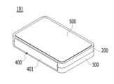
도 1은 본 발명의 일 실시예에 따른 디스플레이 장치의 사시도이고, 도 2는 도 1의 디스플레이 장치가 폴딩된 상태를 보여준다.FIG. 1 is a perspective view of a display device according to an embodiment of the present invention, and FIG. 2 shows the display device of FIG. 1 in a folded state.
도 1 및 도 2를 참조하면, 본 발명의 일 실시예에 따른 디스플레이 장치(101)는 내측 패널(100), 제1 프레임(200), 제2 프레임(300), 폴딩 힌지부(400), 및 외측 패널(500)을 포함한다.1 and 2, the
여기서 패널(100, 500)은 플렉서블 유기 발광 디스플레이 패널, 플렉서블 전기 영동 디스플레이 패널, 플렉서블 전자 습윤 디스플레이 패널, 또는 플렉서블 양자점 디스플레이 패널 등이 될 수 있다. 내측 패널(100)은 폴딩되면 제1 프레임(200)과 제2 프레임(300)의 내측에 위치하게 되며, 외측 패널(500)은 제1 프레임(200) 또는 제2 프레임(300)의 외측에 위치할 수 있다.Here, the
이처럼 패널(100, 500)은 폴딩된 상태에서 내측과 외측에 모두 위치할 수 있으며, 내측 패널(100) 또는 외측 패널(500) 중 하나의 패널만 구성될 수도 있다. 이하, 내측 패널(100)과 외측 패널(500)은 '패널'로 통칭하기로 한다.In this way, the
패널(100)은 복수의 화소를 갖는 화소 어레이에 의해 영상을 표시하는 표시 영역을 포함한다. 도 1을 참조하면, 패널(100)의 표시 영역(R1, R2)은 제1 프레임(200)이 위치한 제1 표시 영역(R1)과, 제2 프레임(300)이 위치한 제2 표시 영역(R2)과, 벤딩 영역(F)을 포함할 수 있다. 즉, 제1 프레임(200)과 제2 프레임(300)은 벤딩 영역(F)을 사이에 두고, 인접 배치될 수 있다.The panel 100 includes a display area that displays an image by a pixel array having a plurality of pixels. Referring to FIG. 1, the display areas R1 and R2 of the panel 100 include a first display area R1 where the
제1 프레임(200)은 패널(100)의 제1 표시 영역(R1)에 해당하는 각종 부품들을 지지하거나 내측에 수용하고, 제2 프레임(300)은 패널(100)의 제2표시 영역에 해당하는 각종 부품들을 지지하거나 내측에 수용할 수 있다.The
선택적으로, 제1 표시 영역(R1)과 제2 표시 영역(R2)은 서로 동일할 크기를 가질 수 있지만, 이에 한정되지 않고, 어느 하나가 넓은 크기를 가질 수 있다. 이 경우, 패널(100)의 접힘 상태에서, 상대적으로 넓은 크기를 갖는 표시 영역의 일부는 외부로 노출되며, 외부로 노출된 표시 영역의 일부는 디스플레이 장치(101)의 오프시에도 날짜,시간, 배터리 잔량, 알림 등이 계속 표시될 수 있다.Optionally, the first display area R1 and the second display area R2 may have the same size, but are not limited to this, and either one may have a large size. In this case, in the folded state of the panel 100, a portion of the display area having a relatively large size is exposed to the outside, and the portion of the display area exposed to the outside displays the date, time, and information even when the
벤딩 영역(F)은 패널(100)의 제1 표시 영역(R1)과 제2 표시 영역(R2) 사이로 정의될 수 있으며 그 영역은 가변될 수 있다. 즉, 벤딩 영역(F)은 폴딩에 따라 평면 상태로 펼쳐지거나 일정한 곡률 반경을 갖는 곡면 형태로 벤딩될 수 있다. 여기서, 폴딩(Foliding)은 벤딩 영역(F)의 접힘 동작 또는 펼침 동작을 포함하는 것으로 정의될 수 있으며, 폴딩 힌지부(400)를 통해 동작이 구현될 수 있다.The bending area F may be defined between the first display area R1 and the second display area R2 of the panel 100, and the area may be variable. That is, the bending area F may be unfolded in a flat state or bent into a curved shape with a constant radius of curvature according to folding. Here, folding may be defined as including a folding or unfolding operation of the bending area F, and the operation may be implemented through the
폴딩 힌지부(400)는 제1 프레임(200)과 상기 제2 프레임(300)의 사이에 배치되며, 제1 프레임(200)과 제2 프레임(300)이 폴딩되도록 하면서 패널(100)의 벤딩을 제어할 수 있다.The
도 3은 일 실시예에 따른 폴딩 힌지부의 사시도로서 언폴딩 상태를 보여주고, 도 4는 도 3의 폴딩 힌지부의 폴딩 상태를 보여주며, 도 5는 도 3의 폴딩 힌지부의 분해 사시도이고, 도 6은 도 5의 부분 확대도이며, 도 7은 도 6의 제1 힌지링크와 제2 힌지링크가 결합된 상태를 보여주고, 도 8은 도 6의 힌지 브라켓의 확대도이며, 도 9는 도 6의 힌지링크, 힌지 브라켓, 패널지지판의 결합 상태를 보여주는 도면이다.Figure 3 is a perspective view of the folding hinge part according to an embodiment and shows the unfolded state, Figure 4 shows the folding state of the folding hinge part of Figure 3, Figure 5 is an exploded perspective view of the folding hinge part of Figure 3, and Figure 6 is a partial enlarged view of FIG. 5, FIG. 7 shows a state in which the first and second hinge links of FIG. 6 are combined, FIG. 8 is an enlarged view of the hinge bracket of FIG. 6, and FIG. 9 is an enlarged view of the hinge bracket of FIG. 6. This is a drawing showing the combined state of the hinge link, hinge bracket, and panel support plate.
도 3 내지 도 9를 참조하면, 폴딩 힌지부(400)는 한 쌍의 패널지지판(410), 제1 힌지링크(440), 제2 힌지링크(450), 한 쌍의 패널지지판(410)의 양측에 각각 배치되는 한 쌍의 힌지 브라켓(420, 430)을 포함하여 구성될 수 있다.Referring to FIGS. 3 to 9, the
패널지지판(410)은 패널(100)을 지지하며, 서로 이격되도록 한 쌍으로 구성될 수 있다. 패널지지판(410)은 폴딩시 패널(100)의 위치가 변화되도록 패널을 지지할 수 있다. 한 쌍의 패널지지판(410)은 각각 제1 프레임(200)에 위치한 제1 표시 영역(R1) 및 벤딩 영역(F) 일부와, 제2 프레임(300)에 위치한 제2 표시 영역(R2) 및 벤딩 영역(F) 일부를 가변하면서 지지할 수 있다. 패널지지판(410)은 플립-플랍(Flip-Flop)으로 명칭될 수 있다.The panel support plate 410 supports the panel 100 and may be configured as a pair to be spaced apart from each other. The panel support plate 410 can support the panel 100 so that the position of the panel 100 changes when folded. The pair of panel support plates 410 each includes a portion of the first display area (R1) and the bending area (F) located on the
예를 들어 패널지지판(410)들은 상면이 편평하고 세로 방향으로 긴 플레이트 형상을 가지며, 벤딩 영역(F) 중심에서 서로 마주보도록 배치될 수 있다. (여기서 세로 방향은 벤딩 영역(F)과 나란하도록 길게 배치되는 방향을 의미하고, 가로 방향은 세로 방향과 수직을 이루는 방향을 말한다.)For example, the panel support plates 410 have a flat upper surface and a longitudinally long plate shape, and may be arranged to face each other at the center of the bending area F. (Here, the vertical direction refers to the direction in which the device is arranged long and parallel to the bending area (F), and the horizontal direction refers to the direction perpendicular to the vertical direction.)
여기서 각각의 패널지지판(410)은 도 6에 도시된 바와 같이, 길이 방향, 즉 세로 방향의 양 측면에 각각 형성된 핀삽입홀(413)을 포함할 수 있다. 이때, 핀삽입홀(413)은 패널지지판(410)의 일측 가장자리 영역, 즉 편심 방향에 위치할 수 있다. 핀삽입홀(413)에는 후술할 지지판 회전핀(415)이 결합되고, 지지판 회전핀(415)은 힌지 브라켓(420, 430)에 결합되어 패널지지판(410)은 편심 회전하는 동작이 이루어질 수 있다. 지지판 회전핀(415)은 플립-플랍 핀(Flip-Flop Pin),으로 명칭될 수 있다.Here, as shown in FIG. 6, each panel support plate 410 may include pin insertion holes 413 formed on both sides in the longitudinal direction, that is, the vertical direction. At this time, the pin insertion hole 413 may be located in an edge area on one side of the panel support plate 410, that is, in an eccentric direction. A support plate rotation pin 415, which will be described later, is coupled to the pin insertion hole 413, and the support plate rotation pin 415 is coupled to the hinge brackets 420 and 430, so that the panel support plate 410 can perform an eccentric rotation operation. . The support plate rotation pin 415 may be called a flip-flop pin.
제1 힌지링크(440)와 제2 힌지링크(450)는 한 쌍의 패널지지판(410) 아래에 각각 배치되고, 폴딩 중심축(445, 도 7 및 도 11 참조)을 중심으로 이동가능하게 결합될 수 있다. 폴딩 중심축(445)은 제1 프레임(200)과 제2 프레임(300)의 폴딩 동작이 이루어지면서 벤딩 영역(F)이 변화하게 되는 중심축을 의미한다. 제1 힌지링크(440)와 제2 힌지링크(450)에는 폴딩 중심축(445)이 결합되는 연결축 삽입홀(444, 454)이 형성될 수 있다. 폴딩 중심축(445)는 후술할 링크 연결핀(445)으로 실시될 수 있다. 링크 연결핀(445)는 링크핀(Lik Pin)으로 명명할 수 있다.The first hinge link 440 and the second hinge link 450 are respectively disposed below a pair of panel support plates 410 and are movably coupled about the folding central axis 445 (see FIGS. 7 and 11). It can be. The folding central axis 445 refers to the central axis along which the bending area F changes as the
보다 상세하게는, 도 6에 도시된 바와 같이 제1 힌지링크(440)는 세로 방향으로 긴 바(bar) 형상의 세로부재(440a)와, 세로부재(440a)의 양측 단부에서 가로 방향으로 각각 연장된 가로부재(440b)를 포함할 수 있다. 세로부재(440a)는 폴딩 중심축(445)으로부터 멀어지는 방향, 즉 외측에 위치할 수 있고, 가로부재(440b)는 폴딩 중심축(445)에 가까워지는 방향, 즉 내측에 위치할 수 있다.More specifically, as shown in FIG. 6, the first hinge link 440 includes a vertical member 440a in the shape of a long bar in the vertical direction, and a horizontal member 440a at both ends of the vertical member 440a, respectively. It may include an extended horizontal member 440b. The vertical member 440a may be located in a direction away from the folding central axis 445, that is, on the outside, and the horizontal member 440b may be located in a direction approaching the folding central axis 445, that is, on the inside.
제1 힌지링크(440)는 세로부재(440a)와 가로부재(440b)의 연결 지점, 즉 세로부재(440a)의 양측면 외측으로 돌출되는 한 쌍의 제1 슬롯핀(441)이 위치할 수 있다. 즉, 제1 슬롯핀(441)은 제1 힌지링크(440)의 외측에 위치할 수 있다.The first hinge link 440 may be located at the connection point between the vertical member 440a and the horizontal member 440b, that is, a pair of first slot pins 441 protruding outward from both sides of the vertical member 440a. . That is, the first slot pin 441 may be located outside the first hinge link 440.
또한, 제1 힌지링크(440)의 세로부재(440a)에는 상술한 패널지지판(410)의 슬라이딩 이동을 위해 경사진 형상의 제1 슬라이딩 돌기(446)가 길이방향을 따라 다수개 형성될 수 있다. 제1 슬라이딩 돌기(446)는 내측에서 외측을 향해 세로부재(440a)의 두께가 얇아지도록 경사가 형성될 수 있다.In addition, a plurality of first sliding protrusions 446 of an inclined shape may be formed along the longitudinal direction on the vertical member 440a of the first hinge link 440 for the sliding movement of the panel support plate 410 described above. . The first sliding protrusion 446 may be inclined so that the thickness of the vertical member 440a becomes thinner from the inside to the outside.
또한, 제1 힌지링크(440)는 가로부재(440b)의 중심 영역, 즉 폴딩 중심축(445)을 이루는 위치에 각각 관통 형성되는 한 쌍의 제1 연결핀 삽입홀(444)과, 가로부재(440b)의 단부에 위치하는 한 쌍의 제1 힌지축 삽입홀(443)을 포함할 수 있다. 제1 힌지축 삽입홀(443)에는 제1 힌지축(425)이 삽입되면서 힌지 브라켓(420)에 제1 힌지링크(440)가 회전가능하게 장착될 수 있다.In addition, the first hinge link 440 has a pair of first connection pin insertion holes 444 each formed through the central area of the horizontal member 440b, that is, at a position forming the folding central axis 445, and a pair of first connection pin insertion holes 444 formed through each of the horizontal members 440b. It may include a pair of first hinge shaft insertion holes 443 located at the ends of (440b). The first hinge shaft 425 may be inserted into the first hinge shaft insertion hole 443 and the first hinge link 440 may be rotatably mounted on the hinge bracket 420.
제2 힌지링크(450)는 세로 방향으로 긴 플레이트 형상을 가지며, 제1 힌지링크(440)와 이동가능하게 결합된다.The second hinge link 450 has a longitudinally long plate shape and is movably coupled to the first hinge link 440.
제2 힌지링크(450)는 측면부 외측에는 한 쌍의 제2 슬롯핀(451)이 위치할 수 있다. 제2 힌지링크(450)에는 상술한 패널지지판(410)의 슬라이딩 이동을 위해 경사진 형상의 제2 슬라이딩 돌기(456)가 길이방향을 따라 다수개가 형성될 수 있다. 제2 슬라이딩 돌기(456)는 내측에서 외측을 향해 두께가 얇아지도록 경사가 형성될 수 있다.The second hinge link 450 may have a pair of second slot pins 451 located on the outside of the side portion. A plurality of inclined second sliding protrusions 456 may be formed along the longitudinal direction of the second hinge link 450 for sliding movement of the panel support plate 410 described above. The second sliding protrusion 456 may be inclined so that its thickness becomes thinner from the inside to the outside.
또한, 제2 힌지링크(450)는 폴딩 중심축(445)을 이루는 위치, 즉 제2 힌지링크(450)의 측면부 중심 영역에는 제1 연결축 삽입홀(444)과 각각 연통되는 한 쌍의 제2 연결축 삽입홀(454)이 형성되고, 제2 힌지링크(450)의 양측면 내측에는 한 쌍의 제2 힌지축 삽입홀(453)이 관통 형성될 수 있다. 제2 힌지축 삽입홀(453)에는 제2 힌지축(435)이 삽입되면서 힌지 브라켓(430)에 제2 힌지링크(450)가 회전가능하게 장착될 수 있다.In addition, the second hinge link 450 is located at a position forming the folding central axis 445, that is, in the center area of the side portion of the second hinge link 450, a pair of second hinge links each communicate with the first connection shaft insertion hole 444. Two connecting shaft insertion holes 454 are formed, and a pair of second hinge shaft insertion holes 453 may be formed through the inner sides of both sides of the second hinge link 450. The second hinge shaft 435 is inserted into the second hinge shaft insertion hole 453 and the second hinge link 450 can be rotatably mounted on the hinge bracket 430.
여기서 상술한 제1 힌지링크(440)와 제2 힌지링크(450)가 서로 이동가능하게 결합하도록 폴딩 힌지부(400)는 제1 연결축 삽입홀(444)과 제2 연결축 삽입홀(454)에 삽입되며 폴딩 중심축(445)을 이루는 한 쌍의 링크 연결핀(445)을 포함할 수 있다.Here, the
한 쌍의 링크 연결핀(445)은 원형의 단면 형상을 가지며, 각각의 제1 연결축 삽입홀(444) 및 제2 연결축 삽입홀(454)에 삽입되면서 폴딩 중심축(445)을 이룰 수 있다. 따라서 제1 힌지링크(440)와 제2 힌지링크(450)는 폴딩 중심축(445)을 이루는 링크 연결핀(445)에 의해 회전가능하게 상호 결합될 수 있다. 이때 제1 힌지링크(440)와 제2 힌지링크(450)는, 도 7에 도시된 바와 같이 제1 힌지링크(440)의 형상으로 인해 내측에 빈 공간을 두고 회전하도록 결합될 수 있다.The pair of link connection pins 445 have a circular cross-sectional shape and can form the folding central axis 445 by being inserted into each of the first connection shaft insertion hole 444 and the second connection shaft insertion hole 454. there is. Accordingly, the first hinge link 440 and the second hinge link 450 can be rotatably coupled to each other by the link connecting pin 445 forming the folding central axis 445. At this time, the first hinge link 440 and the second hinge link 450 can be coupled to rotate with an empty space inside due to the shape of the first hinge link 440, as shown in FIG. 7.
또한, 제1 힌지링크(440)와 제2 힌지링크(450)의 결합체의 상부에는 도 9에 도시된 바와 같이 상술한 한 쌍의 패널지지판(410)이 배치될 수 있다. 이때, 한 쌍의 패널지지판(410)은 각각 제1 힌지링크(440)와 제2 힌지링크(450)의 상술한 제1 슬라이딩 돌기(446)와 제2 슬라이딩 돌기(446)와 각각 접촉될 수 있다.In addition, the pair of panel support plates 410 described above may be disposed on the upper part of the combination of the first hinge link 440 and the second hinge link 450, as shown in FIG. 9. At this time, the pair of panel support plates 410 may be in contact with the above-described first sliding protrusion 446 and second sliding protrusion 446 of the first hinge link 440 and the second hinge link 450, respectively. there is.
힌지 브라켓(420, 430)은 한 쌍의 패널지지판(410)과 제1 힌지링크(440) 및 제2 힌지링크(450)를 이동 가능하게 지지하며 제1 프레임(200)과 상기 제2 프레임(300)에 각각 결합되도록 한 쌍으로 이루어질 수 있다.The hinge brackets 420 and 430 movably support a pair of panel support plates 410, the first hinge link 440, and the second hinge link 450, and support the
이를 위해 각각의 힌지 브라켓(420, 430)은 도 8에 도시된 바와 같이, 회전핀 장착홀(423, 433), 슬롯핀 가이드(422, 432), 힌지축 고정홀(424, 434) 및 프레임 고정홀(427, 437)을 포함할 수 있다.For this purpose, each hinge bracket (420, 430), as shown in FIG. 8, includes rotation pin mounting holes (423, 433), slot pin guides (422, 432), hinge axis fixing holes (424, 434), and a frame. It may include fixing holes (427, 437).
회전핀 장착홀(423, 433)에는 지지판 회전핀(415)이 삽입되면서 패널지지판(410)을 회전가능하게 지지할 수 있다. 상술한 바와 같이 패널지지판(410)에는 핀삽입홀(413)이 형성되어 있고, 지지판 회전핀(415)은 핀삽입홀(413)과 회전핀 장착홀(423, 433)에 각각 삽입되어 힌지 브라켓(420, 430)에 패널지지판(410)을 이동가능하게 결합시킬 수 있다.The panel support plate 410 can be rotatably supported by inserting the support plate rotation pin 415 into the rotation pin mounting holes 423 and 433. As described above, a pin insertion hole 413 is formed in the panel support plate 410, and the support plate rotation pin 415 is inserted into the pin insertion hole 413 and the rotation pin mounting holes 423 and 433, respectively, to form a hinge bracket. The panel support plate 410 can be movably coupled to (420, 430).
슬롯핀 가이드(422, 432)에는 제1 힌지링크(440)와 제2 힌지링크(450)에 각각 돌출 형성된 제1 슬롯핀(441)과 제2 슬롯핀(451)이 각각 삽입될 수 있다. 예를 들어 슬롯핀 가이드(422, 432)는 제1 슬롯핀(441) 또는 제2 슬롯핀(451)이 이동가능하게 결합되는 장공 형상을 가질 수 있다.A first slot pin 441 and a second slot pin 451 protruding from the first hinge link 440 and the second hinge link 450, respectively, may be inserted into the slot pin guides 422 and 432. For example, the slot pin guides 422 and 432 may have a long hole shape to which the first slot pin 441 or the second slot pin 451 is movably coupled.
힌지축 고정홀(424, 434)은 제1 힌지축 삽입홀(443) 또는 제2 힌지축 삽입홀(453)과 연통될 수 있다. 예를 들어 힌지축 고정홀(424, 434)은 내부에 빈 공간을 두도록 한 쌍으로 이루어질 수 있다.The hinge shaft fixing holes 424 and 434 may communicate with the first hinge shaft insertion hole 443 or the second hinge shaft insertion hole 453. For example, the hinge shaft fixing holes 424 and 434 may be formed as a pair to leave an empty space inside.
힌지축 고정홀(424, 434)은 상술한 제1 힌지링크(440) 또는 제2 힌지링크(450)가 힌지 브라켓(420, 430)에 이동가능하게 결합될 수 있도록 한다.The hinge shaft fixing holes 424 and 434 allow the above-described first hinge link 440 or second hinge link 450 to be movably coupled to the hinge brackets 420 and 430.
이를 위해 폴딩 힌지부(400)는 제1 힌지축 삽입홀(443)과 제1 힌지축 고정홀(424), 또는 제2 힌지축 삽입홀(453)과 제2 힌지축 고정홀(434)에 체결되는 한 쌍의 힌지축(425, 435)을 더 포함할 수 있다. 힌지축(425, 435)은 힌지축핀 또는 브라켓 핀(Bracket Pin)으로 명칭할 수 있다.For this purpose, the
힌지 브라켓(420, 430)에는 제1 프레임(200) 또는 제2 프레임(300)과의 결합을 위한 결합공(427, 437)이 형성될 수 있다. 예를 들어 결합공(427, 437)은 힌지 브라켓(420, 430)의 상면에 다수개가 형성되는 볼트공일 수 있으나 이에 제한되지 않고 다양하게 변형실시될 수 있다.The hinge brackets 420 and 430 may be provided with coupling holes 427 and 437 for coupling to the
한편, 폴딩 힌지부(400)에서 상술한 제1 힌지링크(440)와 제2 힌지링크(450)는 폴딩 동작동안, 도 11에 도시된 바와 같이 제1 프레임(200)과 제2 프레임(300)의 외측에서 노출될 수 있다. 따라서 폴딩 힌지부(400)는 제1 힌지링크(440)와 제2 힌지링크(450)의 외부를 감싸는 커버부재(401, 도 2 참조)를 더 포함할 수 있다.Meanwhile, the first hinge link 440 and the second hinge link 450 described above in the
상술한 구성을 포함하는 실시예의 디스플레이 장치(1)는 폴딩 힌지부(400)에 의해 다음과 같이 동작할 수 있다.The display device 1 of the embodiment including the above-described configuration can operate as follows by the
도 10 및 도 11은 폴딩 힌지부의 (A) 외측면 방향 (B) 내측면 방향에서 바라본 동작도들이고, 도 12 및 도 13은 본 발명의 동작을 보충 설명하기 위한 도면들이다.Figures 10 and 11 are operation diagrams viewed from the (A) outer side direction (B) inner side direction of the folding hinge part, and Figures 12 and 13 are diagrams for supplementary explanation of the operation of the present invention.
도 10을 참조하면, 폴딩 힌지부(400)의 패널지지판(410)가 평행한 상태에 위치할 경우, 패널지지판(410)의 하부에 위치한 제1 힌지링크(440)와 제2 힌지링크(450)는 제1 슬롯핀(441)과 제2 슬롯핀(451)이 슬롯핀 가이드(422, 432)의 일측 가장자리에 위치한 상태에 놓이면서 나란하게 펼쳐진 힌지 브라켓(420, 430)에서 움직이지 않고 고정될 수 있다.Referring to FIG. 10, when the panel support plate 410 of the
또한, 도 12 및 도 13을 참조하면, 제1 프레임(200) 또는 제2 프레임(300) 내측에 고정된 텐션 블록(Tension Block, 700)과 슬라이드 플레이트(Slide Plate, 600) 사이에 위치하는 스프링(Spring, 900)의 압축력이 작용하여 슬라이드 플레이트(600)를 지속적으로 밀어줌으로써 패널(100)에 텐션을 가해줄 수 있다. 따라서 패널(100)은 패널지지판(410)에 의해 평행한 상태로 지지되면서, 폴딩 구간이 완전히 닫히는 견고한 구조를 제공함으로써 외부 하중에 의한 충분한 내구성을 확보할 수 있다. 또한 언폴딩시 패널(100)의 변형을 빨리 회복시킴으로써 표면기복(Waviness)를 개선할 수 있다.In addition, referring to FIGS. 12 and 13, a spring located between a tension block (700) fixed to the inside of the first frame (200) or the second frame (300) and a slide plate (600) The compressive force of (Spring, 900) acts to continuously push the slide plate 600, thereby applying tension to the panel 100. Accordingly, the panel 100 is supported in a parallel state by the panel support plate 410 and provides a sturdy structure in which the folding section is completely closed, thereby ensuring sufficient durability against external loads. Additionally, the surface waviness can be improved by quickly recovering the deformation of the panel 100 upon unfolding.
도 11을 참조하면, 폴딩 힌지부(400)를 통해 패널(100)이 내측에 위치하도록 힌지 브라켓(420, 430)에 연결된 제1 프레임(200) 또는 제2 프레임(300)을 폴딩하게 되면 패널(100)은 벤딩 영역을 발생시키면서 휘어지고, 힌지 브라켓(420, 430)들은 서로 마주보도록 위치할 수 있다.Referring to FIG. 11, when the
이때, 제1 힌지링크(440)와 제2 힌지링크(450)는 폴딩 중심축(445)을 중심으로 위치가 변화될 수 있다. 즉, 폴딩 동작시 제1 힌지링크(440)와 제2 힌지링크(450)의 제1 슬롯핀(441)과 제2 슬롯핀(451)은 힌지 브라켓(420, 430)의 슬롯핀 가이드(422, 432)의 일측 가장자리에서 타측 가장자리까지 점점 이동하게 되고, 제1 힌지링크(440)와 제2 힌지링크(450)의 제1 슬라이딩 돌기(446)과 제2 슬라이딩 돌기(456)가 패널지지판(410)을 점점 편심회전 시키게 된다.At this time, the positions of the first hinge link 440 and the second hinge link 450 may be changed around the folding central axis 445. That is, during the folding operation, the first slot pin 441 and the second slot pin 451 of the first hinge link 440 and the second hinge link 450 are connected to the slot pin guide 422 of the hinge brackets 420 and 430. , 432) gradually moves from one edge to the other edge, and the first sliding protrusion 446 and the second sliding protrusion 456 of the first hinge link 440 and the second hinge link 450 are connected to the panel support plate ( 410) is gradually rotated eccentrically.
따라서 패널지지판(410)은 지지판 회전핀(415)을 중심으로 편심 이동하면서 패널(100)을 가압하여 벤딩 영역을 만들고, 제1 슬롯핀(441)과 제2 슬롯핀(451)이 힌지 브라켓(420, 430)의 슬롯핀 가이드(422, 432)의 타측 가장자리에 오는 위치에서 폴딩을 완료시킬 수 있다.Therefore, the panel support plate 410 presses the panel 100 while moving eccentrically around the support plate rotation pin 415 to create a bending area, and the first slot pin 441 and the second slot pin 451 are connected to the hinge bracket ( Folding can be completed at a position near the other edge of the slot pin guides 422 and 432 (420, 430).
한편, 실시예의 디스플레이 장치(101)는 도 11의 (B)에 도시된 바와 같이 제1 프레임(200)과 제2 프레임(300)의 폴딩이 완료된 상태에서 알 수 있듯이, 패널지지판(410)들의 사이에 위치한 벤딩 영역에는 빈 공간이 충분하게 이루어지게 되므로 패널(100)의 휠 수 있는 충분한 공간을 확보할 수 있다. 즉, 패널지지판(410)은 제1 힌지링크(440)와 제2 힌지링크(450)의 동작에 따라서 폴딩 회전 각도만큼 움직이면서, 언폴딩시에는 패널(100)을 받치고, 폴딩시에는 공간을 형성한다.Meanwhile, in the
이와 같이 본 발명의 디스플레이 장치에 따르면, 원활한 폴딩이 이루어지면서도 폴딩 구간이 완전히 닫히는 견고한 구조를 제공함으로써 외부 하중에 의한 충분한 내구성을 확보할 수 있고, 패널이 휠 수 있는 충분한 공간 확보가 가능하므로 베젤의 폭을 축소시킬 수 있다.In this way, according to the display device of the present invention, it is possible to secure sufficient durability against external loads by providing a sturdy structure in which the folding section is completely closed while smooth folding is achieved, and it is possible to secure sufficient space for the panel to bend, so that the bezel The width of can be reduced.
상술한 본 발명의 실시예에 따른 디스플레이 장치는 TV, 스마트폰, 태블릿 PC 등 다양한 전자 장비에 적용될 수 있다.The display device according to the embodiment of the present invention described above can be applied to various electronic devices such as TVs, smartphones, and tablet PCs.
이상에서 실시 예들에 설명된 특징, 구조, 효과 등은 본 발명의 적어도 하나의 실시 예에 포함되며, 반드시 하나의 실시 예에만 한정되는 것은 아니다. 나아가, 각 실시 예에서 예시된 특징, 구조, 효과 등은 실시 예들이 속하는 분야의 통상의 지식을 가지는 자에 의해 다른 실시 예들에 대해서도 조합 또는 변형되어 실시 가능하다. 따라서 이러한 조합과 변형에 관계된 내용들은 본 발명의 범위에 포함되는 것으로 해석되어야 할 것이다.The features, structures, effects, etc. described in the embodiments above are included in at least one embodiment of the present invention and are not necessarily limited to only one embodiment. Furthermore, the features, structures, effects, etc. illustrated in each embodiment can be combined or modified and implemented in other embodiments by a person with ordinary knowledge in the field to which the embodiments belong. Therefore, contents related to such combinations and modifications should be construed as being included in the scope of the present invention.
101 : 디스플레이 장치100 : 내측 패널
200 : 제1 프레임300 : 제2 프레임
400 : 폴딩 힌지부500 : 외측 패널
410 : 패널지지판413 : 핀삽입홀
415 : 지지판 회전핀420, 430 : 힌지 브라켓
440 : 제1 힌지링크440a : 세로부재
440b : 가로부재450 : 제2 힌지링크
422, 432 : 슬롯핀 가이드423, 433 : 회전핀 장착홀
424, 434 : 힌지축 고정홀425, 435 : 힌지축
441 : 제1 슬롯핀442 : 측면링크
443 : 힌지축 삽입홀445 : 링크 연결핀
444, 454 : 연결핀 삽입홀451 : 제2 슬롯핀
453 : 힌지축 삽입홀445, 445 : 슬라이딩 돌기101: display device 100: inner panel
200: 1st frame 300: 2nd frame
400: folding hinge part 500: outer panel
410: Panel support plate 413: Pin insertion hole
415: Support plate rotation pin 420, 430: Hinge bracket
440: first hinge link 440a: vertical member
440b: horizontal member 450: second hinge link
422, 432: Slot pin guide 423, 433: Rotating pin mounting hole
424, 434: Hinge axis fixing hole 425, 435: Hinge axis
441: first slot pin 442: side link
443: Hinge axis insertion hole 445: Link connection pin
444, 454: Connection pin insertion hole 451: 2nd slot pin
453: Hinge axis insertion hole 445, 445: Sliding protrusion
Claims (16)
Translated fromKorean상기 제1 및 제2 프레임 내측에 배치되는 패널; 및
상기 제1 프레임과 상기 제2 프레임의 폴딩을 가능하게 하며, 상기 제1 및 제2 프레임에 결합되는 폴딩 힌지부;를 포함하며,
상기 폴딩 힌지부는,
상기 패널의 위치가 변화되도록 상기 패널을 지지하며, 서로 이격되는 한 쌍의 패널지지판;
상기 한 쌍의 패널지지판 아래에 각각 배치되고, 폴딩 중심축을 중심으로 이동가능하게 결합되는 제1 및 제2 힌지링크;
상기 한 쌍의 패널지지판과 상기 제1 및 제2 힌지링크를 이동 가능하게 지지하며 상기 제1 프레임과 상기 제2 프레임에 각각 결합되는 한 쌍의 힌지 브라켓을 포함하고,
상기 제1 힌지링크는
세로 방향으로 긴 바 형상을 갖는 세로부재;
상기 세로부재의 양측 단부에서 가로 방향으로 각각 연장된 한 쌍의 가로부재;
상기 세로부재의 길이 방향을 따라 구비되며, 경사진 형상을 갖는 제1 슬라이딩 돌기;
상기 세로부재의 양 단부에 돌출된 한 쌍의 제1 슬롯핀;
상기 가로부재에 각각 형성되는 한 쌍의 제1 연결핀 삽입홀; 및
상기 가로부재의 단부에 각각 위치하는 한 쌍의 제1 힌지축 삽입홀을 포함하는, 디스플레이 장치.first and second frames adjacent to each other;
a panel disposed inside the first and second frames; and
It includes a folding hinge unit that enables folding of the first frame and the second frame and is coupled to the first and second frames,
The folding hinge part is,
a pair of panel support plates that support the panel so that the position of the panel can be changed and are spaced apart from each other;
first and second hinge links respectively disposed below the pair of panel support plates and movably coupled about a folding central axis;
It includes a pair of hinge brackets that movably support the pair of panel support plates and the first and second hinge links and are respectively coupled to the first frame and the second frame,
The first hinge link is
A vertical member having a long bar shape in the vertical direction;
a pair of horizontal members each extending in the horizontal direction from both ends of the vertical member;
a first sliding protrusion provided along the longitudinal direction of the vertical member and having an inclined shape;
a pair of first slot pins protruding from both ends of the vertical member;
a pair of first connection pin insertion holes formed in each of the horizontal members; and
A display device comprising a pair of first hinge axis insertion holes each located at an end of the horizontal member.
상기 패널지지판은 길이 방향의 양 측면에 형성된 핀삽입홀을 포함하며,
상기 폴딩 힌지부는 상기 핀삽입홀에 각각 삽입되어 상기 힌지 브라켓에 상기 패널지지판을 이동가능하게 결합시키는 지지판 회전핀을 더 포함하는, 디스플레이 장치.According to paragraph 1,
The panel support plate includes pin insertion holes formed on both sides in the longitudinal direction,
The folding hinge portion further includes support plate rotation pins that are respectively inserted into the pin insertion holes and movably couple the panel support plate to the hinge bracket.
상기 핀삽입홀은 상기 패널지지판이 편심 회전하도록 상기 패널지지판의 일측 가장자리 영역에 위치하는, 디스플레이 장치.According to paragraph 2,
The pin insertion hole is located in an edge area of one side of the panel support plate so that the panel support plate rotates eccentrically.
상기 힌지 브라켓은 상기 지지판 회전핀이 삽입되는 회전핀 장착홀을 포함하는, 디스플레이 장치.According to paragraph 3,
The hinge bracket includes a rotation pin mounting hole into which the support plate rotation pin is inserted.
상기 제2 힌지링크는 세로 방향으로 긴 플레이트 형상을 갖는, 디스플레이 장치.According to paragraph 2,
The second hinge link is a display device having a plate shape that is long in the vertical direction.
상기 제2 힌지링크는
측면부 외측의 양 단부에 돌출된 한 쌍의 제2 슬롯핀;
측면부에 각각 형성되며 상기 한 쌍의 제1 연결핀 삽입홀과 각각 연통되는 한 쌍의 제2 연결핀 삽입홀;
측면부 내측의 양 단부에 각각 위치하는 한 쌍의 제2 힌지축 삽입홀;을 포함하는, 디스플레이 장치.According to clause 8,
The second hinge link is
A pair of second slot pins protruding from both ends outside the side portion;
a pair of second connection pin insertion holes each formed on a side portion and each communicating with the pair of first connection pin insertion holes;
A display device comprising: a pair of second hinge shaft insertion holes respectively located at both ends of the inner side of the side portion.
상기 제2 힌지링크는
길이 방향을 따라 구비되며, 경사진 형상을 갖는 제2 슬라이딩 돌기를 더 포함하는, 디스플레이 장치.According to clause 9,
The second hinge link is
A display device further comprising a second sliding protrusion provided along the longitudinal direction and having an inclined shape.
상기 폴딩 힌지부는 상기 제1 및 제2 연결핀 삽입홀에 삽입되며 상기 폴딩 중심축을 이루며, 상기 제1 및 제2 힌지링크를 회전 가능하게 결합시키는 한 쌍의 링크 연결핀을 더 포함하는, 디스플레이 장치.According to clause 10,
The folding hinge portion is inserted into the first and second connection pin insertion holes and forms the folding central axis, and further includes a pair of link connection pins that rotatably couple the first and second hinge links. .
상기 한 쌍의 힌지 브라켓은
상기 지지판 회전핀이 각각 장착되는 한 쌍의 회전핀 장착홀;
상기 제1 또는 제2 슬롯핀이 각각 이동가능하게 삽입되는 한 쌍의 슬롯핀 가이드; 및
상기 제1 또는 제2 힌지축 삽입홀과 연통되는 한 쌍의 힌지축 고정홀;을 포함하는, 디스플레이 장치.According to clause 11,
The pair of hinge brackets
a pair of rotation pin mounting holes in which the support plate rotation pins are respectively mounted;
a pair of slot pin guides into which the first or second slot pins are respectively movably inserted; and
A display device comprising: a pair of hinge shaft fixing holes communicating with the first or second hinge shaft insertion hole.
상기 폴딩 힌지부는 상기 제1 및 제2 힌지축 삽입홀, 상기 힌지축 고정홀에 체결되는 한 쌍의 힌지축을 더 포함하는, 디스플레이 장치.According to clause 12,
The folding hinge unit further includes a pair of hinge shafts fastened to the first and second hinge shaft insertion holes and the hinge shaft fixing holes.
상기 슬롯핀 가이드는 상기 제1 및 제2 슬롯핀이 이동가능하게 결합되는 장공 형상을 갖는, 디스플레이 장치.According to clause 13,
The slot pin guide has a long hole shape where the first and second slot pins are movably coupled.
상기 한 쌍의 힌지 브라켓에는 상기 제1 프레임 또는 상기 제2 프레임과 결합을 위한 결합공이 형성된, 디스플레이 장치.According to clause 14,
A display device in which a coupling hole for coupling to the first frame or the second frame is formed in the pair of hinge brackets.
상기 폴딩 힌지부는 제1 힌지링크와 제2 힌지링크를 덮는 커버부재를 더 포함하는, 디스플레이 장치.According to any one of claims 1 to 4 and 8 to 15,
The folding hinge portion further includes a cover member covering the first hinge link and the second hinge link.
Priority Applications (9)
| Application Number | Priority Date | Filing Date | Title |
|---|---|---|---|
| KR1020180142473AKR102650633B1 (en) | 2018-11-19 | 2018-11-19 | Display device |
| US16/582,714US11073870B2 (en) | 2018-11-19 | 2019-09-25 | Display device |
| CN202210340166.2ACN114627766B (en) | 2018-11-19 | 2019-10-14 | Display device |
| CN201910977199.6ACN111199687B (en) | 2018-11-19 | 2019-10-14 | display device |
| EP19205580.4AEP3654319B1 (en) | 2018-11-19 | 2019-10-28 | Display device |
| EP24150667.4AEP4325820A3 (en) | 2018-11-19 | 2019-10-28 | Display device |
| KR1020240035937AKR20240039102A (en) | 2018-11-19 | 2024-03-14 | Display device |
| KR1020240035935AKR20240037222A (en) | 2018-11-19 | 2024-03-14 | Display device |
| KR1020240035936AKR20240038948A (en) | 2018-11-19 | 2024-03-14 | Display device |
Applications Claiming Priority (1)
| Application Number | Priority Date | Filing Date | Title |
|---|---|---|---|
| KR1020180142473AKR102650633B1 (en) | 2018-11-19 | 2018-11-19 | Display device |
Related Child Applications (3)
| Application Number | Title | Priority Date | Filing Date |
|---|---|---|---|
| KR1020240035935ADivisionKR20240037222A (en) | 2018-11-19 | 2024-03-14 | Display device |
| KR1020240035936ADivisionKR20240038948A (en) | 2018-11-19 | 2024-03-14 | Display device |
| KR1020240035937ADivisionKR20240039102A (en) | 2018-11-19 | 2024-03-14 | Display device |
Publications (2)
| Publication Number | Publication Date |
|---|---|
| KR20200058020A KR20200058020A (en) | 2020-05-27 |
| KR102650633B1true KR102650633B1 (en) | 2024-03-25 |
Family
ID=68382269
Family Applications (4)
| Application Number | Title | Priority Date | Filing Date |
|---|---|---|---|
| KR1020180142473AActiveKR102650633B1 (en) | 2018-11-19 | 2018-11-19 | Display device |
| KR1020240035936APendingKR20240038948A (en) | 2018-11-19 | 2024-03-14 | Display device |
| KR1020240035937APendingKR20240039102A (en) | 2018-11-19 | 2024-03-14 | Display device |
| KR1020240035935APendingKR20240037222A (en) | 2018-11-19 | 2024-03-14 | Display device |
Family Applications After (3)
| Application Number | Title | Priority Date | Filing Date |
|---|---|---|---|
| KR1020240035936APendingKR20240038948A (en) | 2018-11-19 | 2024-03-14 | Display device |
| KR1020240035937APendingKR20240039102A (en) | 2018-11-19 | 2024-03-14 | Display device |
| KR1020240035935APendingKR20240037222A (en) | 2018-11-19 | 2024-03-14 | Display device |
Country Status (4)
| Country | Link |
|---|---|
| US (1) | US11073870B2 (en) |
| EP (2) | EP4325820A3 (en) |
| KR (4) | KR102650633B1 (en) |
| CN (2) | CN114627766B (en) |
Families Citing this family (22)
| Publication number | Priority date | Publication date | Assignee | Title |
|---|---|---|---|---|
| CN109992054B (en)* | 2019-03-30 | 2021-04-13 | 联想(北京)有限公司 | Electronic equipment and connecting device |
| US11737223B2 (en)* | 2019-04-12 | 2023-08-22 | Samsung Electronics Co., Ltd | Foldable electronic device including a sliding-type hinge structure beneath a flexible display |
| KR102794470B1 (en)* | 2019-05-10 | 2025-04-11 | 삼성전자 주식회사 | Housing, manufacturing method thereof, and electronic device including the same |
| KR102724538B1 (en)* | 2019-07-26 | 2024-11-04 | 삼성디스플레이 주식회사 | Display device |
| KR102784368B1 (en)* | 2019-12-02 | 2025-03-19 | 엘지디스플레이 주식회사 | Foldable display device |
| CN111240413B (en)* | 2020-01-16 | 2022-05-31 | 京东方科技集团股份有限公司 | Electronic device |
| KR20210097258A (en)* | 2020-01-29 | 2021-08-09 | 삼성디스플레이 주식회사 | Foldable display device |
| KR20220001038A (en) | 2020-06-26 | 2022-01-05 | 삼성디스플레이 주식회사 | Display device |
| KR102816913B1 (en)* | 2020-07-10 | 2025-06-10 | 삼성전자주식회사 | Electronic device including flexible display |
| KR20220056294A (en)* | 2020-10-27 | 2022-05-06 | 삼성디스플레이 주식회사 | Display device |
| KR20220082957A (en)* | 2020-12-10 | 2022-06-20 | 삼성디스플레이 주식회사 | Display device |
| CN112788162B (en)* | 2020-12-25 | 2022-09-20 | 厦门天马微电子有限公司 | Folding screen bending mechanism and mobile terminal |
| KR20220126326A (en) | 2021-03-08 | 2022-09-16 | 삼성디스플레이 주식회사 | Digitizers and Indicators |
| CN115234569B (en)* | 2021-04-25 | 2024-01-09 | 北京小米移动软件有限公司 | Connection module and display terminal |
| KR20240076393A (en)* | 2021-09-27 | 2024-05-30 | 보에 테크놀로지 그룹 컴퍼니 리미티드 | Pivotable support device and display device |
| CN217010905U (en)* | 2021-10-19 | 2022-07-19 | 荣耀终端有限公司 | Rotating Mechanisms, Supporting Devices and Electronic Equipment |
| CN114393812B (en)* | 2022-01-13 | 2024-04-19 | 玛尔斯检测技术(苏州)有限公司 | Flexible screen water drop type bending jig structure |
| CN115273662B (en)* | 2022-07-15 | 2024-11-19 | 深圳市联建光电有限公司 | A flexible LED display screen and display device |
| KR102658378B1 (en)* | 2022-07-25 | 2024-04-16 | 윤태중 | Hinge apparatus for foldable device |
| KR102576270B1 (en)* | 2022-07-25 | 2023-09-06 | 윤태중 | Hinge apparatus for foldable device |
| CN119641783A (en)* | 2023-09-18 | 2025-03-18 | 富世达股份有限公司 | Hinge |
| WO2025079828A1 (en)* | 2023-10-13 | 2025-04-17 | 삼성전자주식회사 | Hinge assembly and electronic device comprising same |
Citations (6)
| Publication number | Priority date | Publication date | Assignee | Title |
|---|---|---|---|---|
| KR101386220B1 (en) | 2012-06-26 | 2014-04-17 | 삼성디스플레이 주식회사 | A flexible display device |
| US20140111954A1 (en) | 2012-10-19 | 2014-04-24 | Samsung Display Co., Ltd. | Foldable display device |
| US20150233162A1 (en)* | 2014-02-17 | 2015-08-20 | Samsung Electronics Co., Ltd. | Hinge device and foldable display apparatus having the same |
| US20160014919A1 (en)* | 2013-12-24 | 2016-01-14 | Polyera Corporation | Support structures for a flexible electronic component |
| US20170115701A1 (en) | 2015-04-09 | 2017-04-27 | Samsung Electronics Co., Ltd. | Foldable device |
| KR101891568B1 (en) | 2016-12-01 | 2018-08-27 | 주식회사 이랜텍 | Coupled hinges and flexible display device using the same |
Family Cites Families (20)
| Publication number | Priority date | Publication date | Assignee | Title |
|---|---|---|---|---|
| KR0142473B1 (en) | 1995-05-31 | 1998-08-17 | 김광호 | Programmable voltage amplifier maintaining uniformly unit gain band width of closed loop |
| KR101636077B1 (en)* | 2009-09-14 | 2016-07-05 | 삼성전자주식회사 | Portable terminal |
| US8971031B2 (en)* | 2012-08-07 | 2015-03-03 | Creator Technology B.V. | Display system with a flexible display |
| US9798359B2 (en)* | 2014-02-21 | 2017-10-24 | Samsung Electronics Co., Ltd. | Foldable device |
| KR102244807B1 (en)* | 2014-03-07 | 2021-04-26 | 엘지디스플레이 주식회사 | Foldable display apparatus |
| KR102235171B1 (en)* | 2014-09-01 | 2021-04-02 | 엘지디스플레이 주식회사 | Foldable display apparatus |
| KR102233119B1 (en)* | 2014-09-23 | 2021-03-30 | 삼성디스플레이 주식회사 | Display device |
| US10883534B2 (en)* | 2015-04-09 | 2021-01-05 | Samsung Electronics Co., Ltd. | Foldable device |
| CN106255935B (en) | 2015-04-09 | 2019-09-24 | 三星电子株式会社 | Folding device |
| KR101665365B1 (en) | 2015-06-10 | 2016-10-12 | (주) 프렉코 | Hinge Device with The Cam Structure for Flexible Display |
| KR102366516B1 (en) | 2015-08-31 | 2022-02-22 | 엘지디스플레이 주식회사 | Foldable display apparatus |
| KR102487504B1 (en)* | 2016-08-30 | 2023-01-12 | 삼성디스플레이 주식회사 | Electronic device and operating method of the same |
| KR102680246B1 (en) | 2016-11-30 | 2024-07-01 | 엘지디스플레이 주식회사 | Folding Device of Foldable Display and Display Device having the same |
| CN106601130B (en) | 2016-12-12 | 2019-03-05 | 上海天马微电子有限公司 | Folding flexible display device |
| KR102506381B1 (en) | 2016-12-26 | 2023-03-07 | (주)에이유플렉스 | Hinge Device in both Infolding and Outfolding Way |
| CN207053559U (en)* | 2017-01-26 | 2018-02-27 | 广东欧珀移动通信有限公司 | Housing assembly, display device and mobile terminal |
| KR102688971B1 (en) | 2017-02-22 | 2024-07-25 | 삼성디스플레이 주식회사 | Foldable display device |
| CN108648629B (en) | 2018-05-18 | 2020-07-03 | 栾北瓯 | Rotating shaft mechanism for flexible display screen |
| CN112005187B (en)* | 2018-08-31 | 2024-09-17 | 惠普发展公司,有限责任合伙企业 | Suspension for display |
| TWI710309B (en)* | 2019-03-25 | 2020-11-11 | 兆利科技工業股份有限公司 | A hinge module for the foldable type device |
- 2018
- 2018-11-19KRKR1020180142473Apatent/KR102650633B1/enactiveActive
- 2019
- 2019-09-25USUS16/582,714patent/US11073870B2/enactiveActive
- 2019-10-14CNCN202210340166.2Apatent/CN114627766B/enactiveActive
- 2019-10-14CNCN201910977199.6Apatent/CN111199687B/enactiveActive
- 2019-10-28EPEP24150667.4Apatent/EP4325820A3/enactivePending
- 2019-10-28EPEP19205580.4Apatent/EP3654319B1/enactiveActive
- 2024
- 2024-03-14KRKR1020240035936Apatent/KR20240038948A/enactivePending
- 2024-03-14KRKR1020240035937Apatent/KR20240039102A/enactivePending
- 2024-03-14KRKR1020240035935Apatent/KR20240037222A/enactivePending
Patent Citations (6)
| Publication number | Priority date | Publication date | Assignee | Title |
|---|---|---|---|---|
| KR101386220B1 (en) | 2012-06-26 | 2014-04-17 | 삼성디스플레이 주식회사 | A flexible display device |
| US20140111954A1 (en) | 2012-10-19 | 2014-04-24 | Samsung Display Co., Ltd. | Foldable display device |
| US20160014919A1 (en)* | 2013-12-24 | 2016-01-14 | Polyera Corporation | Support structures for a flexible electronic component |
| US20150233162A1 (en)* | 2014-02-17 | 2015-08-20 | Samsung Electronics Co., Ltd. | Hinge device and foldable display apparatus having the same |
| US20170115701A1 (en) | 2015-04-09 | 2017-04-27 | Samsung Electronics Co., Ltd. | Foldable device |
| KR101891568B1 (en) | 2016-12-01 | 2018-08-27 | 주식회사 이랜텍 | Coupled hinges and flexible display device using the same |
Also Published As
| Publication number | Publication date |
|---|---|
| CN111199687A (en) | 2020-05-26 |
| CN114627766A (en) | 2022-06-14 |
| KR20200058020A (en) | 2020-05-27 |
| EP3654319A1 (en) | 2020-05-20 |
| EP4325820A3 (en) | 2024-04-17 |
| US11073870B2 (en) | 2021-07-27 |
| KR20240037222A (en) | 2024-03-21 |
| CN111199687B (en) | 2022-04-22 |
| EP3654319B1 (en) | 2024-02-21 |
| EP4325820A2 (en) | 2024-02-21 |
| US20200163239A1 (en) | 2020-05-21 |
| CN114627766B (en) | 2024-10-29 |
| KR20240038948A (en) | 2024-03-26 |
| KR20240039102A (en) | 2024-03-26 |
Similar Documents
| Publication | Publication Date | Title |
|---|---|---|
| KR102650633B1 (en) | Display device | |
| CN111210722B (en) | display device | |
| KR102675919B1 (en) | Display device | |
| KR102578842B1 (en) | Display device | |
| CN105609001B (en) | Flexible display | |
| US20220264755A1 (en) | Rollable display device | |
| KR20240106100A (en) | Display device |
Legal Events
| Date | Code | Title | Description |
|---|---|---|---|
| PA0109 | Patent application | Patent event code:PA01091R01D Comment text:Patent Application Patent event date:20181119 | |
| PG1501 | Laying open of application | ||
| A201 | Request for examination | ||
| PA0201 | Request for examination | Patent event code:PA02012R01D Patent event date:20211101 Comment text:Request for Examination of Application Patent event code:PA02011R01I Patent event date:20181119 Comment text:Patent Application | |
| E902 | Notification of reason for refusal | ||
| PE0902 | Notice of grounds for rejection | Comment text:Notification of reason for refusal Patent event date:20221129 Patent event code:PE09021S01D | |
| E902 | Notification of reason for refusal | ||
| PE0902 | Notice of grounds for rejection | Comment text:Notification of reason for refusal Patent event date:20230718 Patent event code:PE09021S01D | |
| E701 | Decision to grant or registration of patent right | ||
| PE0701 | Decision of registration | Patent event code:PE07011S01D Comment text:Decision to Grant Registration Patent event date:20231220 | |
| A107 | Divisional application of patent | ||
| PA0107 | Divisional application | Comment text:Divisional Application of Patent Patent event date:20240314 Patent event code:PA01071R01D | |
| GRNT | Written decision to grant | ||
| PR0701 | Registration of establishment | Comment text:Registration of Establishment Patent event date:20240319 Patent event code:PR07011E01D | |
| PR1002 | Payment of registration fee | Payment date:20240320 End annual number:3 Start annual number:1 | |
| PG1601 | Publication of registration |