KR102649523B1 - Apparatus for draping medical robot - Google Patents
Apparatus for draping medical robotDownload PDFInfo
- Publication number
- KR102649523B1 KR102649523B1KR1020210101763AKR20210101763AKR102649523B1KR 102649523 B1KR102649523 B1KR 102649523B1KR 1020210101763 AKR1020210101763 AKR 1020210101763AKR 20210101763 AKR20210101763 AKR 20210101763AKR 102649523 B1KR102649523 B1KR 102649523B1
- Authority
- KR
- South Korea
- Prior art keywords
- catheter
- base plate
- mounting hole
- medical robot
- manipulator
- Prior art date
- Legal status (The legal status is an assumption and is not a legal conclusion. Google has not performed a legal analysis and makes no representation as to the accuracy of the status listed.)
- Active
Links
Images


Classifications
- A—HUMAN NECESSITIES
- A61—MEDICAL OR VETERINARY SCIENCE; HYGIENE
- A61B—DIAGNOSIS; SURGERY; IDENTIFICATION
- A61B46/00—Surgical drapes
- A61B46/10—Surgical drapes specially adapted for instruments, e.g. microscopes
- A—HUMAN NECESSITIES
- A61—MEDICAL OR VETERINARY SCIENCE; HYGIENE
- A61B—DIAGNOSIS; SURGERY; IDENTIFICATION
- A61B34/00—Computer-aided surgery; Manipulators or robots specially adapted for use in surgery
- A61B34/30—Surgical robots
- A—HUMAN NECESSITIES
- A61—MEDICAL OR VETERINARY SCIENCE; HYGIENE
- A61B—DIAGNOSIS; SURGERY; IDENTIFICATION
- A61B34/00—Computer-aided surgery; Manipulators or robots specially adapted for use in surgery
- A61B34/70—Manipulators specially adapted for use in surgery
- A—HUMAN NECESSITIES
- A61—MEDICAL OR VETERINARY SCIENCE; HYGIENE
- A61M—DEVICES FOR INTRODUCING MEDIA INTO, OR ONTO, THE BODY; DEVICES FOR TRANSDUCING BODY MEDIA OR FOR TAKING MEDIA FROM THE BODY; DEVICES FOR PRODUCING OR ENDING SLEEP OR STUPOR
- A61M25/00—Catheters; Hollow probes
- A61M25/01—Introducing, guiding, advancing, emplacing or holding catheters
- A61M25/0105—Steering means as part of the catheter or advancing means; Markers for positioning
- A61M25/0111—Aseptic insertion devices
- A—HUMAN NECESSITIES
- A61—MEDICAL OR VETERINARY SCIENCE; HYGIENE
- A61B—DIAGNOSIS; SURGERY; IDENTIFICATION
- A61B34/00—Computer-aided surgery; Manipulators or robots specially adapted for use in surgery
- A61B34/30—Surgical robots
- A61B2034/301—Surgical robots for introducing or steering flexible instruments inserted into the body, e.g. catheters or endoscopes
Landscapes
- Health & Medical Sciences (AREA)
- Life Sciences & Earth Sciences (AREA)
- Surgery (AREA)
- Engineering & Computer Science (AREA)
- Animal Behavior & Ethology (AREA)
- Veterinary Medicine (AREA)
- Heart & Thoracic Surgery (AREA)
- Public Health (AREA)
- Biomedical Technology (AREA)
- General Health & Medical Sciences (AREA)
- Molecular Biology (AREA)
- Medical Informatics (AREA)
- Nuclear Medicine, Radiotherapy & Molecular Imaging (AREA)
- Robotics (AREA)
- Biophysics (AREA)
- Pulmonology (AREA)
- Anesthesiology (AREA)
- Hematology (AREA)
- Manipulator (AREA)
Abstract
Translated fromKoreanDescription
Translated fromKorean본 발명은 의료용 로봇의 드레이핑 장치에 관한 것이다.The present invention relates to a draping device for a medical robot.
일반적으로, 수술이란 의사가 수술 도구로 질병이나 외상에 대하여 피부나 점막을 절개하여 시술하는 치료 행위를 말한다. 특히, 수술부위의 피부를 절개하여 열고 그 내부에 있는 기관 등을 치료, 성형하거나 제거하는 개복 수술 등은 출혈, 부작용, 환자의 고통, 흉터 등의 여러가지 문제로 인하여 최근에는 의료용 로봇(robot)을 이용한 수술이 대안으로서 각광받고 있다.In general, surgery refers to a treatment in which a doctor incisions the skin or mucous membrane for a disease or injury using surgical tools. In particular, open surgery, which involves cutting open the skin at the surgical site and treating, shaping or removing the organs inside, has been associated with various problems such as bleeding, side effects, patient pain, and scarring, so medical robots have recently been used. Surgery is gaining attention as an alternative.
수술용 로봇은 의사의 조작에 의해 신호를 생성하여 전송하는 마스터(master)파트와, 그 마스터부로부터 신호를 받아 환자에 대해 수술에 필요한 조작을 수행하는 슬레이브(slave)파트로 구성되며, 마스터 파트와 슬레이브 파트는 통합된 하나의 로봇의 형태로 구현하거나, 각각 별도의
장치로 구현하여 수술실에 배치하게 된다.A surgical robot consists of a master part that generates and transmits signals through the doctor's manipulation, and a slave part that receives signals from the master part and performs the operations necessary for surgery on the patient. The master part The and slave parts can be implemented as an integrated robot, or each can be implemented as a separate robot.
It is implemented as a device and placed in the operating room.
수술용 로봇은 수술을 위한 각종 동작을 수행하는 로봇 암들 구비되고, 그 로봇 암들의 선단부에 메니퓰레이터가 구비되고 그 메니퓰레이터에 수술용 도구(instrument)가 장착되며, 그 수술용 도구는 상황에 따라 다양한 수술용 도구가선택적으로 장착된다. 또한, 메니퓰레이터와 수술용 도구 사이에 멸균 드레이프(sterile drape)가 구비되어 수술용 로봇의 메니퓰레이터를 커버한다.A surgical robot is equipped with robot arms that perform various operations for surgery, a manipulator is provided at the front end of the robot arms, a surgical instrument is mounted on the manipulator, and the surgical tool is Depending on the condition, various surgical tools are optionally installed. Additionally, a sterile drape is provided between the manipulator and the surgical tool to cover the manipulator of the surgical robot.
종래에는 수술용 로봇을 멸균 드레이프로 커버한 후 적절한 부위에서 띠를 감거나 밴드를 체결하는 등의 방법으로 멸균 드레이프를 수술용 로봇에 고정시켰다.Conventionally, the surgical robot was covered with a sterile drape and then the sterile drape was fixed to the surgical robot by wrapping a band or fastening a band at an appropriate area.
그러나 종래 멸균 드레이프는 사용자에 따라 의료용 로봇을 커버하는 위치가 정확하지 못하여 세균 전염 방지 정도가 떨어지고, 의료용 로봇의 아암들마다 멸균 드레이프를 커버한 후 밴드를 체결해야 되므로 드레이핑(draping) 작업이 어렵고 복잡하여 수술 과정 동안 도구를 교환하는 시간이 지체되는 문제점이 있다.However, the conventional sterilized drape is not accurate in the position of covering the medical robot depending on the user, so the degree of prevention of bacterial infection is low, and the draping work is difficult and complicated because each arm of the medical robot must be covered with a sterile drape and then fastened with a band. Therefore, there is a problem that the time to exchange tools during the surgical procedure is delayed.
본 발명의 목적은 의료용 로봇에 반복적으로 교체되어 의료용 로봇에 감염된 세균이 인체에 접촉될 수술 도구를 감염시키는 것을 방지할 뿐만 아니라 설치 작업이 간단한 의료용 로봇의 드레이핑 장치를 제공하는 것이다.The purpose of the present invention is to provide a draping device for a medical robot that is repeatedly replaced by a medical robot and prevents bacteria infected with the medical robot from infecting surgical tools that will come in contact with the human body, as well as simple installation work.
본 발명의 다른 목적은 구성이 간단하고 설치 공간을 최소화하는 의료용 로봇의 드레이핑 장치를 제공하는 것이다.Another object of the present invention is to provide a draping device for a medical robot that is simple in construction and minimizes installation space.
본 발명의 목적을 달성하기 위하여, 내부에 카테터가 착탈 가능하게 장착되는 카테터장착홀이 구비되며 의료용 로봇의 매니퓰레이터에 장착되는 베이스판; 상기 카테터장착홀의 양쪽에 각각 복수 개 직선 움직임 가능하게 구비되며, 상기 카테터의 조작부들과 매니퓰레이터의 구동핀들이 연결되는 연결무빙블록들; 상기 연결무빙블록들이 노출되도록 상기 베이스판의 상면 일부분을 복개하는 커버판; 및 상기 베이스판의 하면에 연결되는 커버필름을 포함하는 의료용 로봇의 드레이핑 장치가 제공된다.In order to achieve the object of the present invention, a base plate is provided with a catheter mounting hole inside which a catheter is detachably mounted and is mounted on a manipulator of a medical robot; A plurality of connection moving blocks are provided on both sides of the catheter mounting hole to enable linear movement, and the operating units of the catheter are connected to the driving pins of the manipulator; a cover plate covering a portion of the upper surface of the base plate to expose the connecting moving blocks; and a cover film connected to the lower surface of the base plate. A draping device for a medical robot is provided.
상기 베이스판은 두께와 면적을 갖는 판부와, 상기 판부의 상면에 상기 커버판에 삽입되는 커버판삽입홈과, 상기 커버판삽입홈의 가운데 관통 형성되는 카테터장착홀과, 상기 카테터장착홀의 폭방향 양쪽에 각각 위치하도록 커버판삽입홈의 저면에 형성되는 슬라이딩홈들과, 상기 카테터장착홀의 폭방향 양쪽에 카테터장착홀과 연통되게 슬라이딩홈들에 각각 형성되는 조작홀들을 포함하는 것이 바람직하다.The base plate includes a plate portion having a thickness and an area, a cover plate insertion groove inserted into the cover plate on the upper surface of the plate portion, a catheter mounting hole formed through the center of the cover plate insertion groove, and a width direction of the catheter mounting hole. It is preferable to include sliding grooves formed on the bottom of the cover plate insertion groove so as to be located on both sides, and operation holes formed in each of the sliding grooves to communicate with the catheter mounting hole on both sides in the width direction of the catheter mounting hole.
상기 연결무빙블록들은 각각 상측에 상기 카테터의 조작부가 삽입되는 조작부삽입홈과 하측에 상기 매니퓰레이터이 조작핀이 삽입되는 핀삽입홈이 구비된 블록본체부와, 상기 블록본체의 양측면에 각각 연장 형성되는 슬라이딩바부를 포함하는 것이 바람직하다.The connection moving blocks each have a block body portion provided with a manipulation part insertion groove on the upper side into which the manipulation part of the catheter is inserted and a pin insertion groove on the lower side into which the manipulation pin of the manipulator is inserted, and a sliding block extending on both sides of the block body, respectively. It is desirable to include Babu.
상기 커버판은 두께와 면적을 갖는 판부와, 상기 판부의 내부에 형성되는 관통홀을 포함하며, 상기 관통홀은 상기 카테터장착홀과 상응하는 크기로 형성되는 장착홀부와, 상기 장착홀부의 폭방향 양측면에 각각 연장 형성되는 슬라이딩홀부들을 포함하는 것이 바람직하다.The cover plate includes a plate portion having a thickness and an area, and a through hole formed inside the plate portion, wherein the through hole includes a mounting hole portion formed in a size corresponding to the catheter mounting hole, and a width direction of the mounting hole portion. It is preferable to include sliding hole portions extending on both sides.
상기 베이스판에 착탈 가능하게 결합되어 상기 연결무빙블록들의 초기 위치를 정렬시키는 고정클립을 더 포함하는 것이 바람직하다.It is preferable to further include a fixing clip that is detachably coupled to the base plate to align the initial positions of the connecting moving blocks.
본 발명은 의료용 로봇의 매니퓰레이터에 장착되어 매니퓰레이터가 연결무빙블록들의 하부에 연결됨과 아울러 매니퓰레이터를 커버하고 카테터의 조작부들이 연결무빙블록들의 상부에 연결되도록 카테터를 본 발명의 베이스판에 장착되고 의료용 로봇의 매니퓰레이터로 연결무빙블록들을 조작함에 의해 카테터를 조작하여 수술을 하게 되므로 의료용 로봇과 그 의료용 로봇에 반복적으로 교체되어 인체와 직접 접촉되는 카테터(또는 의료도구)를 차단시켜 카테터가 세균에 노출되거나 접촉되어 오염되는 것을 방지하게 된다.The present invention is mounted on a manipulator of a medical robot so that the manipulator is connected to the lower part of the connected moving blocks, and the catheter is mounted on the base plate of the present invention so that the manipulator is covered and the operating parts of the catheter are connected to the upper part of the connected moving blocks. Since surgery is performed by manipulating the catheter by manipulating the connected moving blocks with the manipulator, it is repeatedly replaced by the medical robot and the catheter (or medical tool) that is in direct contact with the human body is blocked, preventing the catheter from being exposed to or coming into contact with bacteria. It prevents contamination.
또한, 본 발명은 연결무빙블록들의 각 하부에 로봇의 매니퓰레이터의 구동핀들이 각각 삽입되어 연결되고 연결무빙블록들의 각 상부에 카테터의 조작부들이 각각 삽입되어 연결되므로 로봇의 매니퓰레이터에 연결하는 작업과 카테터를 장착하는 작업이 쉽고 간단하고 정확하게 되어 수술 과정 동안 카테터(또는 의료도구)를 교체하는 시간을 단축시키게 된다.In addition, in the present invention, the driving pins of the robot's manipulator are inserted and connected to each lower part of the connected moving blocks, and the manipulation parts of the catheter are respectively inserted and connected to the upper part of the connected moving blocks, so the operation of connecting to the robot's manipulator and the catheter are performed. The installation process is easy, simple, and accurate, shortening the time required to replace catheters (or medical instruments) during surgical procedures.
또한, 본 발명은 구성이 간단하게 되므로 의료용 로봇에 장착시 설치 공간을 최소화하여 주변 다른 장치들과 충돌이나 간섭을 방지하고 수술실의 이동 공간을 넓게 확보할 수 있게 된다.In addition, since the present invention has a simple configuration, the installation space is minimized when mounted on a medical robot, preventing collision or interference with other surrounding devices and securing a wide movement space in the operating room.
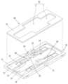
도 1은 본 발명에 따른 의료용 로봇의 드레이핑 장치의 일실시예 및 로봇의 매니퓰레이터, 카테터의 분리된 상태를 도시한 정면도,
도 2는 본 발명에 따른 의료용 로봇의 드레이핑 장치의 일실시예를 도시한 사시도,
도 3은 본 발명에 따른 의료용 로봇의 드레이핑 장치의 일실시예를 분해하여 도시한 사시도,
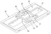
도 4는 본 발명에 따른 의료용 로봇의 드레이핑 장치의 일실시예를 구성하는 베이스판에 고정클립이 장착된 상태를 도시한 사시도,
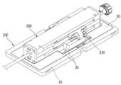
도 5는 본 발명에 따른 의료용 로봇의 드레이핑 장치의 일실시예에 카테터가 장착된 상태를 도시한 사시도.1 is a front view showing an embodiment of the draping device for a medical robot according to the present invention, the robot's manipulator, and the catheter in a separated state;
Figure 2 is a perspective view showing an embodiment of the draping device for a medical robot according to the present invention;
Figure 3 is an exploded perspective view of one embodiment of the draping device for a medical robot according to the present invention;
Figure 4 is a perspective view showing a state in which a fixing clip is mounted on a base plate constituting an embodiment of the draping device for a medical robot according to the present invention;
Figure 5 is a perspective view showing a state in which a catheter is mounted on an embodiment of the draping device for a medical robot according to the present invention.
이하, 본 발명에 따른 의료용 로봇의 드레이핑 장치의 실시예를 첨부도면을 참조하여 설명한다.Hereinafter, an embodiment of the draping device for a medical robot according to the present invention will be described with reference to the accompanying drawings.
도 1은 본 발명에 따른 의료용 로봇의 드레이핑 장치의 일실시예 및 로봇의 매니퓰레이터, 카테터의 분리된 상태를 도시한 정면도이다. 도 2는 본 발명에 따른 의료용 로봇의 드레이핑 장치의 일실시예를 도시한 사시도이다. 도 3은 본 발명에 따른 의료용 로봇의 드레이핑 장치의 일실시예를 분해하여 도시한 사시도이다.Figure 1 is a front view showing an embodiment of the draping device for a medical robot according to the present invention, and the robot's manipulator and catheter in a separated state. Figure 2 is a perspective view showing an embodiment of the draping device for a medical robot according to the present invention. Figure 3 is an exploded perspective view of one embodiment of the draping device for a medical robot according to the present invention.
도 1, 2, 3에 도시한 바와 같이, 본 발명에 따른 의료용 로봇의 드레이핑 장치의 일실시예는, 베이스판(10), 연결무빙블록(20)들, 커버판(30), 커버필름(40)을 포함한다.As shown in Figures 1, 2, and 3, one embodiment of the draping device for a medical robot according to the present invention includes a
본 발명에 따른 의료용 로봇의 드레이핑 장치(100)는 의료용 로봇의 매니퓰레이터(200)를 복개하도록 매니퓰레이터(200)에 장착되고 본 발명에 따른 의료용 로봇의 드레이핑 장치(100)에 카테터(300)가 장착된다.The
베이스판(10)은 내부에 카테터(300)가 착탈 가능하게 장착되는 카테터장착홀이 구비되며 의료용 로봇의 매니퓰레이터(200)에 장착된다. 베이스판(10)의 일예로, 베이스판(10)은 두께와 면적을 갖는 판부(11)와, 그 판부(11)의 상면에 커버판(30)에 삽입되는 커버판삽입홈(12)과, 그 커버판삽입홈(12)의 가운데 관통 형성되는 카테터장착홀(13)과, 그 카테터장착홀(13)의 폭방향 양쪽에 각각 위치하도록 커버판삽입홈(12)의 저면에 형성되는 슬라이딩홈(14)들과, 카테터장착홀(13)의 폭방향 양쪽에 카테터장착홀(13)과 연통되게 슬라이딩홈(14)들에 각각 형성되는 조작홀(15)들을 포함한다. 판부(11)는 사각판 형상인 것이 바람직하다. 커버판삽입홈(12)은 균일한 폭과 길이와 깊이를 갖는 사각홈 형태인 것이 바람직하다. 카테터장착홀(13)은 균일한 폭과 길이를 갖는 사각홀 형태인 것이 바람직하다. 슬라이딩홈(14)들은 각각 균일한 폭과 길이와 깊이를 갖는 사각홈 형태인 것이 바람직하다. 조작홀(15)은 각각 균일한 폭과 길이를 갖는 사각홀 형태인 것이 바람직하다. 판부(11)의 하면에 로봇의 매니퓰레이터(200)에 결합되는 복수 개의 결합돌기(16)들이 구비됨이 바람직하다.The
연결무빙블록(20)들은 카테터장착홀(13)의 양쪽에 각각 복수 개 직선 움직임 가능하게 구비되며, 카테터(300)의 조작부(310)들과 매니퓰레이터(200)의 구동핀(210)들이 연결된다. 연결무빙블록(20)들은 카테터(300)의 조작부(310)의 수와 상응하는 수로 구성된다. 일예로, 연결무빙블록(20)들은 네 개인 것이 바람직하다. 즉, 카테터장착홀(13)의 한쪽에 두 개의 연결무빙블록(20)들이 구비되고 다른 한쪽에 두 개의 연결무빙블록(20)들이 구비된다. 연결무빙블록(20)의 일예로, 연결무빙블록(20)은 상측에 카테터의 조작부(310)가 삽입되는 조작부삽입홈(21)과 하측에 매니퓰레이터이 조작핀(210)이 삽입되는 핀삽입홈(22)이 구비된 블록본체부(23)와, 그 블록본체부(23)의 양측면에 각각 연장 형성되는 슬라이딩바부(24)를 포함한다.A plurality of
연결무빙블록(20)들은 각각 연결무빙블록(20)의 블록본체부(23)가 베이스판(10)의 조작홀(15)에 위치하고 슬라이딩바부(24)들이 각각 슬라이딩홈(14)에 위치하여 슬라이딩바부(24)들의 각 하면이 슬라이딩홈(14)의 저면에 접촉된다. 연결무빙블록(20)은 블록본체부(23)에 직선 왕복 구동력이 가해지게 되면 슬라이딩바부(24)들이 슬라이딩홈(14)의 바닥면을 따라 슬라이딩되면서 직선 왕복하게 된다.The
커버판(30)은 연결무빙블록(20)들이 노출되도록 베이스판(10)의 상면 일부분을 복개한다. 커버판(30)의 일예로, 커버판(30)은 두께와 면적을 갖는 판부(31)와, 그 판부(31)의 내부에 형성되는 관통홀(32)을 포함한다. 관통홀(32)은 카테터장착홀(13)과 상응하는 크기로 형성되는 장착홀부(1)와, 그 장착홀부(1)의 폭방향 양측면에 각각 연장 형성되는 슬라이딩홀부(2)들을 포함한다. 장착홀부(1)는 베이스판(10) 카테터장착홀(13)의 형상 및 크기과 같게 형성되는 것이 바람직하다.The
커버판(30)은 베이스판(10)의 커버판삽입홈(12)에 삽입되어 결합되되, 커버판(30)의 장착홀부(1)가 베이스판(10)의 카테터장착홀(13)과 일치하고 슬라이딩홀부(2)에 연결무빙블록(20)들이 위치하도록 결합된다. 커버판(30)이 베이스판(10)의 커버판삽입홈(12)에 삽입된 상태에서 커버판(30)의 상면과 베이스판(10)의 상면은 동일 평면을 이루는 것이 바람직하다.The
커버필름(40)은 베이스판(10)의 하면에 연결된다. 커버필름(40)은 커버필름(40)은 설정된 크기를 가지며, 내부에 서로 간격을 두고 나란하게 위치하는 두 개의 슬릿홈들이 구비되는 것이 바람직하다. 두 개의 슬릿홈들에 각각 베이스판(10)의 조작홀(15)들은 각각 위치한다.The
베이스판(10)에 연결무빙블록(20)들의 초기 위치를 정렬시키는 고정클립(50)이 착탈 가능하게 결합되는 것이 바람직하다. 고정클립(50)의 일예로, 도 4에 도시한 바와 같이, 고정클립(50)은 내부에 연결무빙블록(20)들이 삽입되는 사각프레임부(51)와, 그 사각프레임부(51)의 양측면에 각각 연장 돌출되어 베이스판(10)에 고정되는 고정돌기부(52)를 포함한다. 사각프레임부(51)의 내부 폭길이는 연결무빙블록(20)의 길이와 같게 형성되는 것이 바람직하다. 고정돌기부(52)는 기역자 형상으로 형성됨이 바람직하다. 베이스판(10)의 양측면에 각각 개구된 결합홈(17)이 구비되는 것이 바람직하다.It is preferable that the fixing
고정클립(50)은 사각프레임부(51)의 내부에 연결무빙블록(20)들이 위치하도록 정렬한 상태에서 고정돌기부(52)들이 베이스판(10)의 결합홈(17)들에 각각 삽입되어 결합된다.The fixing
이하, 본 발명에 따른 의료용 로봇의 드레이핑 장치의 작용과 효과를 설명한다.Hereinafter, the operation and effects of the draping device for a medical robot according to the present invention will be described.
본 발명에 따른 의료용 로봇의 드레이핑 장치(100)는 베이스판(10)이 의료용 로봇의 매니퓰레이터(200)의 일부분을 복개하도록 매니퓰레이터(200)에 장착되고 커버필름(40)이 매니퓰레이터(200)의 그외 부분을 커버한다. 이때, 고정클립(50)이 베이스판(10)에 결합되어 연결무빙블록(20)들이 초기 위치에 위치한 상태이며, 베이스판(10)을 매니퓰레이터(200)에 장착함에 따라 매니퓰레이터(200)의 구동핀(210)들이 연결무빙블록(20)들의 각 핀삽입홈(22)에 삽입된다. 그리고 고정클립(50)을 베이스판(10)으로부터 분리시키고 이어 카테터(300)가 베이스판(10)의 카테터장착홀(13)에 장착된다. 이때, 카테터(300)의 조작부(3100들이 연결무빙블록(20)들의 각 조작부삽입홈(21)에 삽입된다. 이와 같은 상태에서 로봇의 매니퓰레이터(200)의 구동핀(210)들이 각각 직선으로 왕복하면서 작동함에 따라 연결무빙블록(20)들이 함께 움직이면서 그 연결무빙블록(20)들에 연결된 카테터(300)의 조작부(310)들을 움직이게 된다. 조작부(310)들이 움직이면서 카테터(300)로 치료 또는 수술을 하게 된다.The
수술이 끝나고 나면, 카테터(300)를 베이스판(10)으로부터 분리시키고 이어 베이스판(10)을 로봇의 매니퓰레이터(200)로부터 분리시킨다. 그리고 새로운 수술을 하게 될 때 새로운 본 발명 드레이핑 장치(100)를 로봇의 매니퓰레이터(200)에 장작하여 커버하고 베이스판(10)에 새로운 카테터(300)를 장착한다.After the surgery is completed, the
이와 같이, 본 발명은 의료용 로봇의 매니퓰레이터(200)에 장착되어 매니퓰레이터(200)가 연결무빙블록(20)들의 하부에 연결됨과 아울러 매니퓰레이터(200)를 커버하고 카테터(300)의 조작부(310)들이 연결무빙블록(20)들의 상부에 연결되도록 카테터(300)를 본 발명의 베이스판(10)에 장착되고 의료용 로봇의 매니퓰레이터(200)로 연결무빙블록(20)들을 조작함에 의해 카테터(300)를 조작하여 수술을 하게 되므로 의료용 로봇과 그 의료용 로봇에 반복적으로 교체되어 인체와 직접 접촉되는 카테터(300)(또는, 의료도구)를 차단시켜 카테터(300)가 세균에 노출되거나 접촉되어 오염되는 것을 방지하게 된다. 이로 인하여, 의료용 로봇의 멸균 작업을 별도로 수행하지 않아도 된다.In this way, the present invention is mounted on the
또한, 본 발명은 연결무빙블록(20)들의 각 하부에 로봇의 매니퓰레이터(200)의 구동핀(210)들이 각각 삽입되어 연결되고 연결무빙블록(20)들의 각 상부에 카테터(300)의 조작부(310)들이 각각 삽입되어 연결되므로 로봇의 매니퓰레이터(200)에 연결하는 작업과 카테터(300)를 장착하는 작업이 쉽고 간단하고 정확하게 되어 수술 과정 동안 카테터(또는, 의료도구)를 교체하는 시간을 단축시키게 된다.In addition, in the present invention, the driving pins 210 of the
또한, 본 발명은 구성이 간단하게 되므로 의료용 로봇에 장착시 설치 공간을 최소화하여 주변 다른 장치들과 충돌이나 간섭을 방지하고 수술실의 이동 공간을 넓게 확보할 수 있게 된다.In addition, since the present invention has a simple configuration, the installation space is minimized when mounted on a medical robot, preventing collision or interference with other surrounding devices and securing a wide movement space in the operating room.
10; 베이스판20; 연결무빙블록
30; 커버판40; 커버필름
200; 로봇의 매니퓰레이터300; 카테터10;
30;
200;
Claims (5)
Translated fromKorean상기 베이스판의 카테터장착홀 양쪽에 각각 복수 개 직선 움직임 가능하게 구비되며, 상기 카테터의 조작부들과 매니퓰레이터의 구동핀들이 연결되는 연결무빙블록들;
상기 연결무빙블록들이 노출되도록 상기 베이스판의 상면 일부분을 복개하는 커버판;
상기 베이스판의 하면에 연결되는 커버필름; 및
상기 베이스판에 착탈 가능하게 결합되어 상기 연결무빙블록들의 초기 위치를 정렬시키는 고정클립을 포함하며,
상기 베이스판은 두께와 면적을 갖는 판부와, 상기 판부의 상면에 형성되어 상기 커버판이 삽입되는 커버판삽입홈과, 상기 커버판삽입홈의 가운데에 관통 형성되는 카테터장착홀과, 상기 카테터장착홀의 폭방향 양쪽에 각각 위치하도록 커버판삽입홈의 저면에 형성되어 상기 연결무빙블록이 슬라이딩 가능하게 결합되는 슬라이딩홈들과, 상기 카테터장착홀의 폭방향 양쪽에 카테터장착홀과 연통되게 슬라이딩홈들에 각각 형성되는 조작홀과, 상기 판부의 양측면에 각각 개구되게 형성되는 결합홈을 포함하며,
상기 고정클립은 내부에 상기 연결무빙블록들이 삽입되는 사각프레임부와, 상기 사각프레임부의 양측면에 각각 연장 돌출되어 상기 베이스판의 결합홈에 착탈 가능하게 고정되는 고정돌기부를 포함하는 의료용 로봇의 드레이핑 장치.A base plate provided with a catheter mounting hole inside which a catheter is detachably mounted and mounted on a manipulator of a medical robot;
A plurality of connection moving blocks are provided on both sides of the catheter mounting hole of the base plate to enable linear movement, and are connected to the operating portions of the catheter and the driving pins of the manipulator;
a cover plate covering a portion of the upper surface of the base plate to expose the connecting moving blocks;
A cover film connected to the lower surface of the base plate; and
It includes a fixing clip that is detachably coupled to the base plate to align the initial positions of the connecting moving blocks,
The base plate includes a plate portion having a thickness and an area, a cover plate insertion groove formed on the upper surface of the plate portion into which the cover plate is inserted, a catheter mounting hole formed through the center of the cover plate insertion groove, and the catheter mounting hole. Sliding grooves formed on the bottom of the cover plate insertion groove so as to be located on both sides in the width direction, into which the connection moving block is slidably coupled, and sliding grooves in communication with the catheter mounting holes on both sides of the width direction of the catheter mounting hole, respectively. It includes an operating hole formed and a coupling groove formed to be open on each side of the plate part,
The fixing clip is a draping device for a medical robot including a square frame part into which the connection moving blocks are inserted, and fixing protrusions that extend and protrude from both sides of the square frame part and are detachably fixed to the coupling groove of the base plate. .
상기 관통홀은 상기 카테터장착홀과 상응하는 크기로 형성되는 장착홀부와, 상기 장착홀부의 폭방향 양측면에 각각 연장 형성되는 슬라이딩홀부들을 포함하는 의료용 로봇의 드레이핑 장치.The method of claim 1, wherein the cover plate includes a plate portion having a thickness and an area, and a through hole formed inside the plate portion,
The through hole is a draping device for a medical robot including a mounting hole portion formed in a size corresponding to the catheter mounting hole, and sliding hole portions extending on both sides of the mounting hole portion in the width direction.
Priority Applications (1)
| Application Number | Priority Date | Filing Date | Title |
|---|---|---|---|
| KR1020210101763AKR102649523B1 (en) | 2021-08-03 | 2021-08-03 | Apparatus for draping medical robot |
Applications Claiming Priority (1)
| Application Number | Priority Date | Filing Date | Title |
|---|---|---|---|
| KR1020210101763AKR102649523B1 (en) | 2021-08-03 | 2021-08-03 | Apparatus for draping medical robot |
Publications (2)
| Publication Number | Publication Date |
|---|---|
| KR20230020115A KR20230020115A (en) | 2023-02-10 |
| KR102649523B1true KR102649523B1 (en) | 2024-03-20 |
Family
ID=85223585
Family Applications (1)
| Application Number | Title | Priority Date | Filing Date |
|---|---|---|---|
| KR1020210101763AActiveKR102649523B1 (en) | 2021-08-03 | 2021-08-03 | Apparatus for draping medical robot |
Country Status (1)
| Country | Link |
|---|---|
| KR (1) | KR102649523B1 (en) |
Citations (3)
| Publication number | Priority date | Publication date | Assignee | Title |
|---|---|---|---|---|
| JP2007527296A (en) | 2004-03-05 | 2007-09-27 | ハンセン メディカル,インク. | Robotic guide catheter system |
| KR101337281B1 (en) | 2005-12-20 | 2013-12-06 | 인튜어티브 서지컬 인코포레이티드 | Sterile surgical adaptor |
| JP2021052905A (en)* | 2019-09-27 | 2021-04-08 | 株式会社メディカロイド | Adapter set and adapter |
Family Cites Families (2)
| Publication number | Priority date | Publication date | Assignee | Title |
|---|---|---|---|---|
| KR101337278B1 (en)* | 2005-12-20 | 2013-12-09 | 인튜어티브 서지컬 인코포레이티드 | Instrument interface of a robotic surgical system |
| KR101717437B1 (en)* | 2015-07-08 | 2017-03-20 | (주)미래컴퍼니 | Connection structure of wheel and surgical instrument |
- 2021
- 2021-08-03KRKR1020210101763Apatent/KR102649523B1/enactiveActive
Patent Citations (3)
| Publication number | Priority date | Publication date | Assignee | Title |
|---|---|---|---|---|
| JP2007527296A (en) | 2004-03-05 | 2007-09-27 | ハンセン メディカル,インク. | Robotic guide catheter system |
| KR101337281B1 (en) | 2005-12-20 | 2013-12-06 | 인튜어티브 서지컬 인코포레이티드 | Sterile surgical adaptor |
| JP2021052905A (en)* | 2019-09-27 | 2021-04-08 | 株式会社メディカロイド | Adapter set and adapter |
Also Published As
| Publication number | Publication date |
|---|---|
| KR20230020115A (en) | 2023-02-10 |
Similar Documents
| Publication | Publication Date | Title |
|---|---|---|
| US10433925B2 (en) | Sterile barrier for robotic surgical system | |
| ES2982040T3 (en) | Articulated stapling with trigger locking element | |
| US10856933B2 (en) | Surgical instrument housing incorporating a channel and methods of manufacturing the same | |
| US20240081191A1 (en) | Trocar Support | |
| DE69735270T2 (en) | FINGERPIECE INSTRUMENT FOR MINIMAL INVASIVE SURGERY | |
| EP1467671B1 (en) | Apparatus for performing surgery on a patient | |
| US10610312B2 (en) | Modular interface for a robotic system | |
| DE102006059165B4 (en) | Sterile surgical adapter and coupling procedure | |
| KR100998044B1 (en) | Structure introduced into sample collector for biopsy | |
| GB2632968A (en) | Puncture Support and Biopsy Device | |
| JP2016019766A (en) | Multicomponent telepresence system and method thereof | |
| WO1999017661A1 (en) | Subcutaneous endoscopic dissector | |
| KR20220139964A (en) | Sterile Master Input Handle Assemblies for Robotic Surgical Systems and Surgical Draps for Sterile Master Input Handles | |
| KR20180122845A (en) | Surgical instrument equipment appropriate for mini-invasive surgery | |
| IT202000002554A1 (en) | CONTROL STATION FOR ROBOTIC SURGERY, STERILE OPERATIVE FIELD, ROBOTIC SURGERY SYSTEM AND METHOD | |
| KR102649523B1 (en) | Apparatus for draping medical robot | |
| JP2004057520A (en) | Sheath for surgery | |
| US20160317139A1 (en) | Retraction system | |
| KR101475665B1 (en) | Surgical instruments for nasal cavities and surgical instrument assembly | |
| NL2038475B1 (en) | Operating forceps for urological surgery | |
| RU2236186C2 (en) | Device for puncturing echinococcus cysts | |
| CN219461338U (en) | Multichannel single-hole puncture outfit with clamping structure | |
| CN212016096U (en) | Operating table wire fixer | |
| RU2082324C1 (en) | Method for fixing body organs and tissues in laparoscopic and thoracoscopic operations | |
| US11298181B2 (en) | Electrosurgical forceps |
Legal Events
| Date | Code | Title | Description |
|---|---|---|---|
| PA0109 | Patent application | St.27 status event code:A-0-1-A10-A12-nap-PA0109 | |
| PA0201 | Request for examination | St.27 status event code:A-1-2-D10-D11-exm-PA0201 | |
| D13-X000 | Search requested | St.27 status event code:A-1-2-D10-D13-srh-X000 | |
| D14-X000 | Search report completed | St.27 status event code:A-1-2-D10-D14-srh-X000 | |
| PG1501 | Laying open of application | St.27 status event code:A-1-1-Q10-Q12-nap-PG1501 | |
| E902 | Notification of reason for refusal | ||
| PE0902 | Notice of grounds for rejection | St.27 status event code:A-1-2-D10-D21-exm-PE0902 | |
| T11-X000 | Administrative time limit extension requested | St.27 status event code:U-3-3-T10-T11-oth-X000 | |
| E13-X000 | Pre-grant limitation requested | St.27 status event code:A-2-3-E10-E13-lim-X000 | |
| P11-X000 | Amendment of application requested | St.27 status event code:A-2-2-P10-P11-nap-X000 | |
| P13-X000 | Application amended | St.27 status event code:A-2-2-P10-P13-nap-X000 | |
| E701 | Decision to grant or registration of patent right | ||
| PE0701 | Decision of registration | St.27 status event code:A-1-2-D10-D22-exm-PE0701 | |
| PR0701 | Registration of establishment | St.27 status event code:A-2-4-F10-F11-exm-PR0701 | |
| PR1002 | Payment of registration fee | Fee payment year number:1 St.27 status event code:A-2-2-U10-U11-oth-PR1002 | |
| PG1601 | Publication of registration | St.27 status event code:A-4-4-Q10-Q13-nap-PG1601 | |
| P22-X000 | Classification modified | St.27 status event code:A-4-4-P10-P22-nap-X000 | |
| R18-X000 | Changes to party contact information recorded | St.27 status event code:A-5-5-R10-R18-oth-X000 | |
| P22-X000 | Classification modified | St.27 status event code:A-4-4-P10-P22-nap-X000 |