KR102648959B1 - A blood clot retrieval device for removing occluding blood clots from blood vessels. - Google Patents
A blood clot retrieval device for removing occluding blood clots from blood vessels.Download PDFInfo
- Publication number
- KR102648959B1 KR102648959B1KR1020187017658AKR20187017658AKR102648959B1KR 102648959 B1KR102648959 B1KR 102648959B1KR 1020187017658 AKR1020187017658 AKR 1020187017658AKR 20187017658 AKR20187017658 AKR 20187017658AKR 102648959 B1KR102648959 B1KR 102648959B1
- Authority
- KR
- South Korea
- Prior art keywords
- thrombus
- clot
- pinching
- configuration
- struts
- Prior art date
- Legal status (The legal status is an assumption and is not a legal conclusion. Google has not performed a legal analysis and makes no representation as to the accuracy of the status listed.)
- Active
Links
Images


Classifications
- A—HUMAN NECESSITIES
- A61—MEDICAL OR VETERINARY SCIENCE; HYGIENE
- A61B—DIAGNOSIS; SURGERY; IDENTIFICATION
- A61B17/00—Surgical instruments, devices or methods
- A61B17/22—Implements for squeezing-off ulcers or the like on inner organs of the body; Implements for scraping-out cavities of body organs, e.g. bones; for invasive removal or destruction of calculus using mechanical vibrations; for removing obstructions in blood vessels, not otherwise provided for
- A61B17/221—Gripping devices in the form of loops or baskets for gripping calculi or similar types of obstructions
- A—HUMAN NECESSITIES
- A61—MEDICAL OR VETERINARY SCIENCE; HYGIENE
- A61B—DIAGNOSIS; SURGERY; IDENTIFICATION
- A61B17/00—Surgical instruments, devices or methods
- A61B17/32—Surgical cutting instruments
- A61B17/3205—Excision instruments
- A61B17/3207—Atherectomy devices working by cutting or abrading; Similar devices specially adapted for non-vascular obstructions
- A—HUMAN NECESSITIES
- A61—MEDICAL OR VETERINARY SCIENCE; HYGIENE
- A61B—DIAGNOSIS; SURGERY; IDENTIFICATION
- A61B17/00—Surgical instruments, devices or methods
- A61B17/22—Implements for squeezing-off ulcers or the like on inner organs of the body; Implements for scraping-out cavities of body organs, e.g. bones; for invasive removal or destruction of calculus using mechanical vibrations; for removing obstructions in blood vessels, not otherwise provided for
- A61B17/22031—Gripping instruments, e.g. forceps, for removing or smashing calculi
- A61B2017/22034—Gripping instruments, e.g. forceps, for removing or smashing calculi for gripping the obstruction or the tissue part from inside
- A—HUMAN NECESSITIES
- A61—MEDICAL OR VETERINARY SCIENCE; HYGIENE
- A61B—DIAGNOSIS; SURGERY; IDENTIFICATION
- A61B17/00—Surgical instruments, devices or methods
- A61B17/22—Implements for squeezing-off ulcers or the like on inner organs of the body; Implements for scraping-out cavities of body organs, e.g. bones; for invasive removal or destruction of calculus using mechanical vibrations; for removing obstructions in blood vessels, not otherwise provided for
- A61B2017/22072—Implements for squeezing-off ulcers or the like on inner organs of the body; Implements for scraping-out cavities of body organs, e.g. bones; for invasive removal or destruction of calculus using mechanical vibrations; for removing obstructions in blood vessels, not otherwise provided for with an instrument channel, e.g. for replacing one instrument by the other
- A—HUMAN NECESSITIES
- A61—MEDICAL OR VETERINARY SCIENCE; HYGIENE
- A61B—DIAGNOSIS; SURGERY; IDENTIFICATION
- A61B17/00—Surgical instruments, devices or methods
- A61B17/22—Implements for squeezing-off ulcers or the like on inner organs of the body; Implements for scraping-out cavities of body organs, e.g. bones; for invasive removal or destruction of calculus using mechanical vibrations; for removing obstructions in blood vessels, not otherwise provided for
- A61B2017/22094—Implements for squeezing-off ulcers or the like on inner organs of the body; Implements for scraping-out cavities of body organs, e.g. bones; for invasive removal or destruction of calculus using mechanical vibrations; for removing obstructions in blood vessels, not otherwise provided for for crossing total occlusions, i.e. piercing
Landscapes
- Health & Medical Sciences (AREA)
- Surgery (AREA)
- Life Sciences & Earth Sciences (AREA)
- Heart & Thoracic Surgery (AREA)
- Nuclear Medicine, Radiotherapy & Molecular Imaging (AREA)
- Vascular Medicine (AREA)
- Engineering & Computer Science (AREA)
- Biomedical Technology (AREA)
- Medical Informatics (AREA)
- Molecular Biology (AREA)
- Animal Behavior & Ethology (AREA)
- General Health & Medical Sciences (AREA)
- Public Health (AREA)
- Veterinary Medicine (AREA)
- Orthopedic Medicine & Surgery (AREA)
- Surgical Instruments (AREA)
Abstract
Translated fromKoreanDescription
Translated fromKorean본 발명은 혈관으로부터 급성 폐색물(acute blockage)을 제거하도록 의도된 장치에 관한 것이다. 급성 폐색물은 혈전(clot), 잘못 배치된 장치, 이동된 장치, 큰 색전(embolus) 등을 포함할 수 있다. 혈전색전증(thromboembolism)은 혈전의 일부 또는 전부가 혈관 벽으로부터 분리될 때 발생한다. 이러한 혈전(이제, 색전으로 불림)은 이어서 혈류의 방향으로 운반된다. 혈전이 뇌 혈관계(cerebral vasculature)에 머무르면, 허혈성 뇌졸중(ischemic stroke)이 발생할 수 있다. 혈전이 정맥계(venous system)에서 또는 심장의 우측에서 발생하고 폐 동맥(pulmonary artery) 또는 그의 분지부(branch)에 머무르면, 폐 색전증(pulmonary embolism)이 발생할 수 있다. 혈전은 또한 색전의 형태로 방출됨이 없이 국소적으로 발달하여 혈관을 폐색할 수 있다 - 이러한 메커니즘은 관상동맥 폐색물(coronary blockage)의 형성에 흔하다. 본 발명은 급성 허혈성 뇌졸중(acute ischemic stroke, AIS)을 앓고 있는 환자 내의 뇌 동맥으로부터, 심근 경색(myocardial infarction, MI)을 앓고 있는 환자 내의 관상동맥 자연 또는 이식 혈관으로부터, 그리고 폐 색전증(PE)을 앓고 있는 환자 내의 폐 동맥으로부터 그리고 혈전이 폐색을 유발하는 다른 말초 동맥 및 정맥 혈관으로부터 혈전을 제거하는 데 특히 적합하다.The present invention relates to a device intended to remove acute blockage from blood vessels. Acute obstructions may include clots, misplaced devices, displaced devices, and large emboli. Thromboembolism occurs when part or all of a blood clot separates from the blood vessel wall. These blood clots (now called emboli) are then transported in the direction of the bloodstream. If a blood clot stays in the cerebral vasculature, an ischemic stroke may occur. If a blood clot develops in the venous system or on the right side of the heart and lodges in the pulmonary artery or its branches, a pulmonary embolism may occur. Blood clots can also develop locally and occlude blood vessels without being released as an embolus - this mechanism is common in the formation of coronary blockages. The present invention relates to the treatment of pulmonary embolism (PE) from cerebral arteries in patients suffering from acute ischemic stroke (AIS), from coronary native or grafted vessels in patients suffering from myocardial infarction (MI), and from pulmonary embolism (PE). It is particularly suitable for removing blood clots from pulmonary arteries in patients suffering from disease and from other peripheral arteries and venous vessels where the clots are causing occlusion.
본 발명에 따르면, 신체 혈관으로부터 혈전을 제거하기 위한 혈전 제거 장치가 제공되는데, 상기 장치는 확장가능 구조물 및 세장형 부재를 포함하고, 세장형 부재는 근위 단부 및 원위 단부를 갖고, 세장형 부재는 그의 원위 단부에서 확장가능 구조물에 연결되고, 확장가능 구조물은 구속된 전달 구성, 확장된 혈전 결합 전개된 구성, 및 적어도 부분적으로 구속된 혈전 핀칭(pinching) 구성을 갖고, 확장가능 구조물의 적어도 일부는 확장된 전개된 구성에서 혈전과 결합하도록 그리고 전개된 구성으로부터 혈전 핀칭 구성으로의 이동 시 혈전을 핀치하도록 구성된다.According to the present invention, there is provided a thrombectomy device for removing a blood clot from a blood vessel in the body, the device comprising an expandable structure and an elongated member, the elongated member having a proximal end and a distal end, the elongated member comprising: It is connected at its distal end to an expandable structure, wherein the expandable structure has a constrained delivery configuration, an expanded thrombus binding deployed configuration, and an at least partially constrained thrombus pinching configuration, wherein at least a portion of the expandable structure It is configured to engage a thrombus in the extended deployed configuration and to pinch the thrombus upon movement from the deployed configuration to the thrombus pinching configuration.
한 가지 경우에, 확장가능 구조물은 전개된 구성으로부터 혈전 핀칭 구성으로의 이동 시 혈전을 핀치하도록 구성된 혈전 핀칭 구조물을 포함한다.In one case, the expandable structure includes a thrombus pinching structure configured to pinch a thrombus when moved from a deployed configuration to a thrombus pinching configuration.
일 실시예에서, 확장가능 구조물은 본체 부분 및 혈전 핀칭 구조물을 포함하고, 혈전 핀칭 구조물의 직경은 본체 부분의 직경보다 작다. 혈전 핀칭 구조물은 확장가능 구조물의 근위 단부에 위치될 수 있다.In one embodiment, the expandable structure includes a body portion and a thrombus pinching structure, wherein the diameter of the thrombus pinching structure is smaller than the diameter of the body portion. The thrombus pinching structure may be positioned at the proximal end of the expandable structure.
한 가지 경우에, 혈전 핀칭 구조물은 실질적으로 관형이다. 혈전 핀칭 구조물은 나사형 형태(spiral form)를 가질 수 있다.In one case, the thrombus pinching structure is substantially tubular. The thrombus pinching structure may have a spiral form.
일 실시예에서, 혈전 핀칭 구조물은 복수의 혈전 수용 셀들을 포함하고, 하나의 셀은 크라운(crown)들 사이에서 연장된 스트러트들을 포함하고, 스트러트들은 장치가 확장된 전개된 구성으로부터 적어도 부분적으로 구속된 혈전 핀칭 구성으로 이동됨에 따라 셀 내에 위치된 혈전을 핀치하도록 구성된다.In one embodiment, the thrombus pinching structure includes a plurality of thrombus receiving cells, one cell including struts extending between crowns, the struts at least partially restraining the device from an expanded deployed configuration. It is configured to pinch the blood clot located within the cell as it moves into the blood clot pinching configuration.
한 가지 경우에, 인접한 스트러트들은 스트러트들을 결합하는 크라운을 향하여 원위방향으로 좁아지는 채널을 한정한다.In one case, adjacent struts define a channel that narrows distally toward the crown joining the struts.
인접한 스트러트들은 그들 사이에 네크형(necked) 영역을 한정할 수 있는데, 네크형 영역은 장치가 혈전 핀칭 구성으로 이동됨에 따라 폐쇄되도록 구성된다.Adjacent struts may define a necked region between them, the necked region being configured to close as the device is moved into the thrombus pinching configuration.
일 실시예에서, 인접한 셀들의 크라운들은 장치의 종축을 따라서 오프셋된다. 인접한 스트러트들은 상이한 길이들을 가질 수 있다.In one embodiment, the crowns of adjacent cells are offset along the longitudinal axis of the device. Adjacent struts may have different lengths.
한 가지 경우에, 셀은 근위방향 대면 크라운 및 원위방향 대면 크라운을 갖고, 근위방향 대면 크라운은 원위방향 대면 크라운의 직경보다 큰 직경을 갖는다.In one case, the cell has a proximally facing crown and a distally facing crown, with the proximally facing crown having a diameter greater than the diameter of the distally facing crown.
일 실시예에서, 혈전 핀칭 구조물의 근위 단부를 향하는 혈전 수용 셀의 크기는 혈전 핀칭 구조물의 원위 단부를 향하는 셀보다 작다.In one embodiment, the size of the thrombus receiving cells facing the proximal end of the thrombus pinching structure is smaller than the cells facing the distal end of the thrombus pinching structure.
일부 경우에, 인접한 스트러트들은 적어도 하나의 만곡부 또는 파상부(undulation)를 포함하고, 만곡부들은 장치가 혈전 핀칭 구성으로 이동됨에 따라 인접한 스트러트들 내의 만곡부들이 상호결합하도록 구성된다. 스트러트는 그의 길이를 따라서 복수의 만곡부들을 포함할 수 있다.In some cases, adjacent struts include at least one flexure or undulation, and the undulations are configured such that flexures within adjacent struts interlock as the device is moved into the thrombus pinching configuration. The strut may include a plurality of bends along its length.
만곡부들은 스트러트의 원위 단부를 향하여 위치될 수 있다.The bends may be positioned towards the distal end of the strut.
일부 실시예에서, 확장가능 구조물은 니티놀(Nitinol)과 같은 형상 기억 재료로 이루어진다.In some embodiments, the expandable structure is made of a shape memory material such as Nitinol.
일부 경우에, 본체 부분의 직경 대 혈전 핀칭 구조물의 직경의 비는 1.5:1 내지 4:1, 일부 경우에 2:1 내지 3:1이다.In some cases, the ratio of the diameter of the body portion to the diameter of the thrombus pinching structure is 1.5:1 to 4:1, and in some cases 2:1 to 3:1.
본 장치는 본체 부분과 혈전 핀칭 구조물 사이의 전이부에 방사선 불투과성 마커(radiopaque marker)를 포함할 수 있다.The device may include a radiopaque marker at the transition between the main body portion and the clot pinching structure.
본체 부분의 종축은 혈전 핀칭 구조물의 종축과 동일선 상에 있을 수 있다.The longitudinal axis of the body portion may be collinear with the longitudinal axis of the thrombus pinching structure.
일부 경우에, 혈전 핀칭 구조물의 종축은 본체 부분의 종축으로부터 오프셋된다.In some cases, the longitudinal axis of the thrombus pinching structure is offset from the longitudinal axis of the body portion.
일 실시예에서, 장치는 본체 부분을 통하여 연장된 종축을 갖고, 혈전 핀칭 구조물은 종축을 중심으로 나사형으로 연장된다.In one embodiment, the device has a longitudinal axis extending through the body portion and the thrombus pinching structure extends threadedly about the longitudinal axis.
본 발명에 따르면, 신체 혈관으로부터 조직화된 혈전을 제거하기 위한 혈전 제거 장치가 또한 제공되는데, 상기 장치는 확장가능 관형 구조물 및 세장형 부재를 포함하고,According to the present invention, there is also provided a thrombectomy device for removing an organized thrombus from a body blood vessel, the device comprising an expandable tubular structure and an elongated member,
세장형 부재는 근위 단부 및 원위 단부를 포함하고,The elongated member includes a proximal end and a distal end,
확장가능 관형 구조물은 상호연결된 스트러트들의 망(network)을 포함하고, 상기 망은 확장된 상태에서 혈전과 결합하도록 구성되고,The expandable tubular structure includes a network of interconnected struts, the network configured to engage a blood clot in the expanded state,
망은 확장된 상태에서 망의 적어도 일부가 혈전에 상호침투(interpenetrate)하도록 구성되고,The network is configured so that at least a portion of the network interpenetrates the blood clot in the expanded state,
망은 추가로, 망이 혈전과의 상호침투의 상태로부터 접혀진 경우에 망의 적어도 일부가 혈전의 적어도 일부를 핀치하도록 구성된다.The mesh is further configured such that when the mesh is folded from a state of interpenetration with the blood clot, at least a portion of the mesh pinches at least a portion of the blood clot.
세장형 부재는 망이 혈전에 상호침투하고 그리고 망의 적어도 일부가 혈전의 적어도 일부에 대해 핀치를 이루는 상태로 망을 후퇴시키도록 구성된, 전술된 바와 같은 장치가 또한 제공된다.An apparatus as described above is also provided, wherein the elongated member is configured to retract the mesh to a state in which the mesh interpenetrates the thrombus and at least a portion of the mesh is pinched against at least a portion of the thrombus.
본 발명에 따르면, 신체 혈관으로부터 조직화된 혈전을 제거하기 위한 혈전 제거 장치가 또한 제공되는데, 상기 장치는 확장가능 관형 구조물 및 세장형 부재를 포함하고,According to the present invention, there is also provided a thrombectomy device for removing an organized thrombus from a body blood vessel, the device comprising an expandable tubular structure and an elongated member,
세장형 부재는 근위 단부 및 원위 단부를 포함하고, 세장형 부재는 그의 원위 단부에서 관형 구조물에 연결되고,The elongated member includes a proximal end and a distal end, and the elongated member is connected to the tubular structure at its distal end,
확장가능 관형 구조물은 조직화된 혈전과 접촉하도록 전개된 경우에 조직화된 혈전에 상호침투하도록 구성되고,the expandable tubular structure is configured to interpenetrate the organized thrombus when deployed into contact with the organized thrombus;
확장가능 관형 구조물은 단지 일 단부에서 상호연결된 복수의 제1 및 제2 스트러트 부재들을 추가로 포함하고, 각 쌍의 스트러트들은 확장된 구성에 대해 편의된 스프링 요소를 포함하고 적어도 하나의 제1 스프링 요소는 부드러운 스프링 요소를 포함하고 적어도 하나의 제2 스프링 요소는 단단한 스프링 요소를 포함하여 관형 구조물의 접힘이 비대칭이 되게 하고,The expandable tubular structure further includes a plurality of first and second strut members interconnected only at one end, each pair of struts including a spring element biased for the expanded configuration and at least one first spring element. comprises a soft spring element and at least one second spring element comprises a rigid spring element such that the folding of the tubular structure is asymmetric,
구조물의 비대칭 접힘은 제1 스프링 요소의 적어도 일부와의 상호침투 상태에 있는 조직화된 혈전의 일부에 대한 핀치를 이룬다.The asymmetric folding of the structure results in a pinch of a portion of the organized thrombus in interpenetration with at least a portion of the first spring element.
본 발명에 따르면, 신체 혈관으로부터 혈전을 제거하기 위한 혈전 제거 장치가 또한 제공되는데, 상기 장치는 확장가능 구조물 및 세장형 부재를 포함하고,According to the present invention, there is also provided a thrombectomy device for removing a blood clot from a body blood vessel, the device comprising an expandable structure and an elongated member,
세장형 부재는 근위 단부 및 원위 단부를 포함하고, 세장형 부재는 그의 원위 단부에서 확장가능 구조물에 연결되고,The elongated member includes a proximal end and a distal end, and the elongated member is connected to the expandable structure at its distal end,
확장가능 구조물은 적어도 제1 셀 및 적어도 하나의 제2 셀을 포함하고, 상기 제1 및 제2 셀들의 각각은 접혀진 전달 구성 및 전개된 확장된 구성을 포함하고, 확장된 구성에서 각각의 셀은 오리피스를 추가로 포함하고,The expandable structure includes at least a first cell and at least one second cell, each of the first and second cells comprising a collapsed delivery configuration and a deployed expanded configuration, each cell in the expanded configuration Additionally comprising an orifice,
확장가능 구조물은 혈전에 상호침투하도록 구성되고, 상기 혈전의 상호침투는 상기 제1 셀들 중 적어도 하나를 통한 혈전의 적어도 일부의 압출(extrusion)을 포함하여,The expandable structure is configured to interpenetrate a thrombus, wherein the interpenetration of the thrombus comprises extrusion of at least a portion of the thrombus through at least one of the first cells,
셀들의 적어도 일부의 오리피스가 혈전 몸체의 적어도 일부가 구조물에 상호침투하는 것을 허용하도록 구성되게 한다.The orifices of at least some of the cells are configured to allow at least a portion of the thrombus body to interpenetrate the structure.
본 발명에 따르면, 혈관으로부터 폐색 혈전을 제거하기 위한 혈전 회수 장치가 또한 제공되는데, 상기 장치는 혈전 결합 요소를 포함하고, 혈전 결합 요소는 구속된 전달 구성 및 확장된 전개된 구성을 갖고, 혈전 결합 요소는 확장된 전개된 구성의 내경보다 작은 내경을 갖는 내강 내에서 전개되는 경우 외향 반경방향 힘을 인가하도록 구성되고, 상기 외향 반경방향 힘은 혈전 결합 요소의 길이를 따라서 대체적으로 사인 곡선인 패턴으로 가변된다.According to the present invention, there is also provided a thrombus retrieval device for removing an occlusive thrombus from a blood vessel, the device comprising a thrombus binding element, the thrombus binding element having a constrained delivery configuration and an extended deployed configuration, the thrombus binding element The element is configured to apply an outward radial force when deployed within a lumen having an inner diameter that is smaller than the inner diameter of the expanded deployed component, the outward radial force in a generally sinusoidal pattern along the length of the thrombus engagement element. It is variable.
대체적으로 사인 곡선인 패턴은 파형 패턴을 포함하고, 파형 패턴의 진폭은 장치의 길이를 따라서 대체적으로 일관된, 전술된 바와 같은 혈전 회수 장치가 또한 제공된다.A clot retrieval device as described above is also provided, wherein the generally sinusoidal pattern includes a wavy pattern, the amplitude of the wavy pattern being generally consistent along the length of the device.
대체적으로 사인 곡선인 패턴은 파형 패턴을 포함하고, 파형 패턴의 진폭은 장치의 길이를 따라서 감소하고 장치의 근위 단부에서 더 크고 장치의 원위 단부에서 더 작은, 전술된 바와 같은 혈전 회수 장치가 또한 제공된다.A clot retrieval device as described above is also provided, wherein the generally sinusoidal pattern comprises a wavy pattern, the amplitude of the wavy pattern decreasing along the length of the device and being greater at the proximal end of the device and smaller at the distal end of the device. do.
혈전 결합 요소는 복수의 인접한 세그먼트들을 포함하고, 적어도 2개의 인접한 세그먼트들의 반경방향 힘은 서로 상이한, 전술된 바와 같은 혈전 회수 장치가 또한 제공된다.A clot retrieval device as described above is also provided, wherein the clot engagement element comprises a plurality of adjacent segments, wherein the radial forces of at least two adjacent segments are different from each other.
원위 혈전 조각 보호 섹션을 포함하는 위의 어딘가에서 설명된 바와 같은 혈전 회수 장치가 또한 제공된다.A clot retrieval device as described elsewhere above comprising a distal clot fragment protection section is also provided.
본 발명에 따르면, 혈관으로부터 폐색 혈전을 제거하는 방법이 제공되는데, 상기 방법은,According to the present invention, a method is provided for removing an occluding blood clot from a blood vessel, comprising:
혈전 결합 섹션을 갖고, 구속된 전달 구성 및 확장된 전개된 구성을 갖는 혈전 회수 장치를 제공하는 단계; 마이크로카테터를 폐색 혈전을 가로질러 전진시키는 단계;Providing a thrombus retrieval device having a thrombus binding section, the thrombus retrieval device having a constrained delivery configuration and an extended deployed configuration; advancing the microcatheter across the occluding thrombus;
장치를 마이크로카테터 내로 로딩(loading)하고 마이크로카테터의 원위 부분으로 전진시키는 단계;Loading the device into the microcatheter and advancing it to the distal portion of the microcatheter;
장치를 전개하고 혈전 결합 섹션을 혈전과 결합시키도록 마이크로카테터를 후퇴시키는 단계;deploying the device and retracting the microcatheter to engage the thrombus-engaging section with the thrombus;
마이크로카테터를 재전진시켜 혈전 결합 섹션의 적어도 일부를 재피복(resheath)하는 단계; 및Re-advancing the microcatheter to resheath at least a portion of the thrombus-engaged section; and
장치의 적어도 일부 및 캡처된 혈전을 회수 카테터 내로 회수하는 단계를 포함한다.Retrieving at least a portion of the device and the captured thrombus into a retrieval catheter.
이러한 방법의 추가의 변형예가 또한 제공되는데, 이는Additional variations of this method are also provided, which include
회수 카테터는 중간 카테터인 전술된 바와 같은 방법;Method as described above wherein the retrieval catheter is an intermediate catheter;
회수 카테터는 벌룬 가이드 카테터(balloon guide catheter), 또는 가이드 카테터, 또는 피복인 전술된 바와 같은 방법;The method as described above wherein the retrieval catheter is a balloon guide catheter, or guide catheter, or sheath;
혈전 결합 섹션의 일부를 재피복하는 단계는 혈전의 일부가 혈전 결합 섹션의 셀 내에서 핀치되게 하는 전술된 바와 같은 방법;Recovering a portion of the thrombus-binding section may include a method as described above wherein a portion of the thrombus is pinched within the cells of the thrombus-binding section;
혈전 회수 장치는 혈전의 적어도 일부를 핀치하도록 구성된 전술된 바와 같은 방법;The clot retrieval device may include a method as described above configured to pinch at least a portion of a clot;
혈전 내에서 장치의 전개 후에 장치를 근위방향으로 당기는 단계를 포함하는 전술된 바와 같은 방법;A method as described above comprising the step of pulling the device proximally after deployment of the device within the thrombus;
재피복 전에 혈전 내에 추가로 매설하기 위하여 전개 후에 장치를 원위방향으로 미는 것을 지연시키는 단계를 포함하는 전술된 바와 같은 방법;A method as described above comprising delaying distal pushing of the device after deployment to further embed it within the thrombus prior to recoating;
회수 카테터 내로의 회수 전에 더 큰 혈관 내로 장치를 근위방향으로 당기는 단계를 포함하는 전술된 바와 같은 방법을 포함한다.A method as described above comprising pulling the device proximally into a larger blood vessel prior to withdrawal into a retrieval catheter.
혈관 세그먼트로부터 폐색 혈전을 분리(dislodging) 및 제거하는 방법을 포함하는 추가 방법이 제공되는데, 상기 폐색 혈전을 분리 및 제거하는 방법은Additional methods are provided, including a method of dislodging and removing an occlusive thrombus from a vascular segment, the method comprising dislodging and removing an occlusive thrombus.
혈전 회수 장치를 제공하는 단계 - 혈전 회수 장치는 모놀리스식(monolithic) 관형 구조물 및 세장형 부재를 포함하고, 모놀리스식 관형 구조물은 세장형 부재의 원위 단부에 위치되고, 모놀리스식 관형 구조물은 완전히 구속된 전달 구성, 부분적으로 접혀진 핀칭 구성, 및 혈전 결합 전개된 구성을 가짐 -;Providing a clot retrieval device, the clot retrieval device comprising a monolithic tubular structure and an elongated member, the monolithic tubular structure being positioned at a distal end of the elongate member, the monolithic tubular structure comprising: has a fully constrained delivery configuration, a partially folded pinching configuration, and a thrombus-bound unfolded configuration;
세장형 부재가 혈관 세그먼트의 근위 부분 및 환자의 외부를 통하여 연장된 상태에서 모놀리스식 관형 구조물을 그의 완전히 구속된 전달 구성으로부터 그의 혈전 결합 전개된 구성으로 확장시킴으로써 폐색 혈전을 모놀리스식 관형 구조물과 결합시키는 단계;The occluding thrombus is separated from the monolithic tubular structure by extending the monolithic tubular structure from its fully constrained delivery configuration to its thrombus-bound deployed configuration with the elongated member extending through the proximal portion of the vascular segment and exterior to the patient. combining;
폐색 혈전의 적어도 일부에 대한 핀치를 이루기 위하여 모놀리스식 관형 구조물을 혈전 결합 전개된 구성으로부터 부분적으로 접혀진 핀칭 구성으로 부분적으로 접는 단계;partially folding the monolithic tubular structure from a thrombus-binding deployed configuration to a partially folded pinching configuration to achieve a pinch for at least a portion of the occluding thrombus;
모놀리스식 관형 구조물을 부분적으로 접혀진 핀칭 구성으로 감금하는 단계;Confining the monolithic tubular structure into a partially folded pinching configuration;
감금을 유지하면서 모놀리스식 관형 구조물을 후퇴시킴으로써 혈전을 폐색 부위로부터 분리하고 그를 혈관 세그먼트로부터 제거하는 단계를 포함한다.Separating the thrombus from the site of occlusion and removing it from the vascular segment by retracting the monolithic tubular structure while maintaining confinement.
폐색된 혈관을 갖는 환자를 치료하는 방법이 또한 제공되는데, 폐색은 조직화된 혈전을 포함하고, 상기 방법은A method of treating a patient having an occluded blood vessel is also provided, wherein the occlusion comprises an organized thrombus, the method comprising:
혈전 회수 장치 및 제거 카테터를 제공하는 단계 - 혈전 회수 장치는 확장가능 요소 및 세장형 부재를 포함하고, 확장가능 요소는 세장형 부재의 원위 단부에 위치되고, 확장가능 요소는 완전히 접혀진 전달 구성 및 완전히 확장된 전개된 구성을 갖고, 확장가능 요소는 혈전 핀칭 하위구조물을 포함하고, 혈전 핀칭 하위구조물은 확장가능 요소가 완전히 확장된 구성으로부터 적어도 부분적으로 접혀짐에 따라 혈전 몸체의 적어도 일부를 핀치하도록 구성되고, 제거 카테터는 그의 원위 단부에 칼라를 포함함 -;Providing a clot retrieval device and an ablation catheter, the clot retrieval device comprising an expandable element and an elongated member, the expandable element being positioned at a distal end of the elongate member, the expandable element being in a fully collapsed delivery configuration and a completely It has an extended deployed configuration, wherein the expandable element includes a thrombus pinching substructure, the thrombus pinching substructure configured to pinch at least a portion of the thrombus body as the expandable element is at least partially collapsed from the fully expanded configuration. and the ablation catheter includes a collar at its distal end;
혈전 회수 장치를 그의 접혀진 구성으로 마이크로 카테터를 통하여 폐색된 혈관으로 전달하는 단계;delivering the clot retrieval device in its collapsed configuration to the occluded blood vessel via a microcatheter;
확장가능 요소를 혈전의 적어도 일부와 접촉하도록 전개하는 단계;deploying the expandable element to contact at least a portion of the blood clot;
세장형 부재의 위치를 고정 상태로 유지하면서, 세장형 부재를 따라서 제거 카테터를 전진시키는 단계;advancing the ablation catheter along the elongated member while maintaining the position of the elongated member fixed;
조직화된 혈전의 적어도 일부를 핀치하기 위하여 제거 카테터의 칼라를 확장가능 요소와 결합하고 핀칭 하위구조물을 이루는 단계;Combining the collar of the ablation catheter with the expandable element and forming a pinching substructure to pinch at least a portion of the organized thrombus;
칼라와 확장가능 요소 사이의 결합을 유지하면서, 혈관으로부터 제거 카테터 및 혈전 회수 장치를 일제히 인출하는 단계; 및withdrawing the ablation catheter and clot retrieval device simultaneously from the blood vessel while maintaining engagement between the collar and the expandable element; and
혈전 회수 장치, 제거 카테터 및 핀치된 폐색 혈전을 환자로부터 제거하는 단계를 포함한다.A clot retrieval device, an ablation catheter, and removing the pinched occluding clot from the patient.
일부 실시예에서, 장치의 적어도 일부 및 캡처된 혈전을 회수 카테터 내로 회수하는 단계는 회수 카테터를 통하여 흡인하는 단계를 포함한다.In some embodiments, retrieving at least a portion of the device and the captured thrombus into the retrieval catheter includes aspirating through the retrieval catheter.
일부 경우에, 혈전 결합 섹션의 일부를 재피복하는 단계는 혈전의 일부가 혈전 결합 섹션의 셀 내에서 핀치되게 한다.In some cases, recovering a portion of a thrombus-binding section causes a portion of the thrombus to be pinched within the cells of the thrombus-binding section.
일부 실시예에서, 본 방법은 혈전 내에서 장치의 전개 후에 장치를 근위방향으로 당기는 단계를 포함한다.In some embodiments, the method includes pulling the device proximally after deployment of the device within the thrombus.
일부 경우에, 본 방법은 재피복 전에 혈전 내에 추가로 매설하기 위하여 전개 후에 장치를 원위방향으로 미는 것을 지연시키는 단계를 포함한다.In some cases, the method includes delaying the distal push of the device after deployment to further embed it within the thrombus prior to recoating.
일부 실시예에서, 본 방법은 회수 카테터 내로의 회수 전에 더 큰 혈관 내로 장치를 근위방향으로 당기는 단계를 포함한다.In some embodiments, the method includes pulling the device proximally into a larger blood vessel prior to withdrawal into a retrieval catheter.
본 발명은, 첨부 도면을 참조하여, 단지 예로서 주어진, 본 발명의 일부 실시예들의 하기 설명으로부터 더 명확히 이해될 것이다.
도 1a 내지 도 1e는 본 발명의 혈전 회수 장치의 사용 방법을 도시한다.
도 2a 내지 도 2c는 도 1a 내지 도 1e에 도시된 장치의 추가 도면들이다.
도 3a 내지 도 3b는 본 발명의 장치 구성의 등각도 및 길이를 따른 반경방향 힘 분포의 그래프를 도시한다.
도 4a 내지 도 4e는 본 발명의 혈전 회수 장치의 평탄한 구성의 사용 방법을 도시한다.
도 5a 내지 도 5d는 본 발명의 다른 실시예의 일련의 도면들이다.
도 6a 내지 도 6d는 본 발명의 다른 실시예의 일련의 도면들이다.
도 7a 내지 도 7d는 내부 및 외부 반경 구조로 이루어진 본 발명의 장치 조립체를 도시한다.
도 8은 도 7a 내지 도 7d에 도시된 장치의 다른 구성의 측면도이다.
도 9는 외부 케이지(cage)의 일부로서 형성된 본 발명의 이미지이다.
도 10은 도 11에 도시된 외부 케이지 및 내부 채널을 포함하는 장치의 조립체를 도시한다.
도 11은 내부 채널의 일부로서 형성된 본 발명의 도면이다.
도 12는 도 11에 도시된 내부 채널 및 외부 케이지를 포함하는 장치의 조립체를 도시한다.
도 13은 외부 케이지 셀들이 내부 채널 셀들과 정렬된 본 발명의 다른 실시예를 도시한다.
도 14는 도 13에 도시된 외부 케이지의 세그먼트를 도시한다.
도 15는 감소된 직경의 도 13에 도시된 외부 케이지의 세그먼트를 도시한다.
도 16은 도 13에 도시된 내부 채널의 세그먼트를 도시한다.
도 17은 내부 및 외부 구성요소 세그먼트들의 정렬을 도시한다.
도 18은 본 발명의 셀 패턴의 예를 도시한다.
도 19는 다수의 구조물들로 이루어진 본 발명의 실시예를 도시한다.
도 20a 및 도 20b는 맨드릴(mandrel) 상의 중심선 위치 및 장치의 길이를 따라서 나사형을 이루는 본 발명의 혈전 회수 장치를 도시한다.
도 21은 평탄한 중간 섹션을 갖는 다른 나선형(helical) 혈전 회수 장치의 도면이다.
도 22는 윤곽형성된 중간 섹션을 갖는 본 발명의 다른 나선형 혈전 회수 장치를 도시한다.
도 23a 내지 도 23c는 일련의 나사형 장치들의 중간 부분의 단면도를 도시한다.
도 24a 및 도 24b는 본 발명의 다른 나선형 혈전 회수 장치의 도면이다.
도 25는 다수의 나선형 구성요소들로 형성된 장치를 도시한다.
도 26은 일정 장력 하에서 신장될 수 있는 장치의 실시예를 도시한다.
도 27a 및 도 27b는 원위 단편 보호 구조물을 포함하는 본 발명의 실시예를 도시한다.
도 28은 도 27에 도시된 장치의 사용 방법을 도시한다.
도 29는 관형 구성요소가 나선형 또는 나사형 구성으로 형성된 다른 실시예를 도시한다.
도 30은 사용 중에 있는 도 29의 장치를 도시한다.
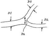
도 31은 혈관 분기부의 도면이다.
도 32a 및 도 32b는 직선 관형 구성요소(도 32a)와 나선형 구성의 관형 구성요소(도 32b)의 혈전의 결합의 차이를 도시한다.
도 33은 혈관 분기부에 위치된 혈전 내에서 전개된 나선형 관형 구성요소의 도면이다.
도 34는 다양한 혈전 유형들의 분리 및 보유에 적합한 본 발명에 따른 다른 장치의 도면이다.
도 35a 및 도 35b는 도 34의 장치의 외부 케이지 구성요소(도 35a) 및 나선형 구성요소(도 35b)를 도시한다.
도 36은 내부 나선형 구성요소 및 외부 케이지를 포함하는 본 발명의 다른 장치의 도면이다.
도 37은 마이크로카테터에 의해 부분적으로 재피복되는 경우에 근위 섹션이 혈전을 핀치하도록 구성된 본 발명에 따른 다른 장치를 도시한다.
도 38 내지 도 44c는 장치들의 다양한 스트러트(strut) 패턴들을 도시한다.
도 43은 본 발명에 따른 장치의 프로파일 및 외부 형상의 도면이다.
도 44a 내지 도 44c는 혈전 핀칭을 촉진하는 스트러트/크라운 구성을 도시한다.
도 45는 본 발명의 다른 장치의 프로파일 및 외부 형상의 도면이다.
도 46은 도 45의 화살표(A)의 방향으로 보았을 때 도 45의 장치의 단부도이다.
도 47은 추가 스트러트 및 연결부가 상세한, 도 45의 장치와 유사한 형상의 장치를 도시한다.
도 48은 외부 샤프트 및 나사형 및 몸체 섹션들의 형상이 도시된 장치의 다른 실시예를 도시한다.
도 49a는 도 6a 내지 도 6d의 장치의 부분 평면도이다.
도 49b 및 도 49c는 사용 중에 있는 도 49a의 장치를 도시한다.
도 50a 내지 도 50c는 마이크로카테터에 의해 재피복되는 종래 기술의 스텐트 회수기(stent retriever) 유형 장치를 도시한다.
도 51a 내지 도 51c는 혈전 내에서 전개된 본 발명의 장치를 도시한다.
도 52a 및 도 52b는 확장된 구성(도52a) 및 수축된 구성(도 52b) 상태에 있는 종래 기술의 스텐트 회수기 유형 장치의 스트러트들을 도시한다.
도 53은 본 발명의 장치의 스트러트 구성을 도시한다.
도 54a 및 도 54b는 본 발명의 장치의 스트러트 구성을 도시한다.The invention will be understood more clearly from the following description of some embodiments of the invention, given by way of example only, with reference to the accompanying drawings.
1A to 1E illustrate a method of using the blood clot recovery device of the present invention.
Figures 2A-2C are additional views of the device shown in Figures 1A-1E.
3A-3B show isometric views of the device configuration of the invention and graphs of the radial force distribution along the length.
4A-4E illustrate a method of using the flat configuration of the blood clot retrieval device of the present invention.
5A to 5D are a series of views of another embodiment of the present invention.
6A to 6D are a series of views of another embodiment of the present invention.
7A-7D illustrate the device assembly of the invention with inner and outer radius structures.
Figure 8 is a side view of another configuration of the device shown in Figures 7A to 7D.
Figure 9 is an image of the invention formed as part of an external cage.
Figure 10 shows the assembly of the device including the outer cage and inner channel shown in Figure 11.
Figure 11 is a diagram of the invention formed as part of an internal channel.
Figure 12 shows the assembly of a device including the inner channel and outer cage shown in Figure 11.
Figure 13 shows another embodiment of the invention in which the outer cage cells are aligned with the inner channel cells.
Figure 14 shows a segment of the outer cage shown in Figure 13.
Figure 15 shows a segment of the outer cage shown in Figure 13 of reduced diameter.
Figure 16 shows a segment of the inner channel shown in Figure 13.
Figure 17 shows the alignment of internal and external component segments.
Figure 18 shows an example of a cell pattern of the present invention.
Figure 19 shows an embodiment of the invention consisting of multiple structures.
20A and 20B illustrate the clot retrieval device of the present invention in a centerline position on a mandrel and threaded along the length of the device.
Figure 21 is a diagram of another helical clot retrieval device with a flat middle section.
Figure 22 shows another helical clot retrieval device of the invention with a contoured middle section.
Figures 23a-23c show cross-sectional views of the middle portion of a series of threaded devices.
Figures 24a and 24b are diagrams of another spiral blood clot recovery device of the present invention.
Figure 25 shows a device formed from multiple helical components.
Figure 26 shows an embodiment of a device that can be stretched under constant tension.
Figures 27A and 27B depict embodiments of the invention comprising a distal fragment protection structure.
Figure 28 shows a method of using the device shown in Figure 27.
Figure 29 shows another embodiment where the tubular component is formed in a helical or threaded configuration.
Figure 30 shows the device of Figure 29 in use.
Figure 31 is a diagram of a blood vessel bifurcation.
Figures 32a and 32b illustrate the differences in the engagement of thrombi of a straight tubular component (Figure 32a) and a tubular component in a helical configuration (Figure 32b).
Figure 33 is a diagram of a spiral tubular component developed within a thrombus located at a vascular bifurcation.
Figure 34 is a diagram of another device according to the invention suitable for separation and retention of various clot types.
Figures 35A and 35B show the outer cage component (Figure 35A) and the helical component (Figure 35B) of the device of Figure 34.
Figure 36 is a diagram of another device of the invention comprising an internal helical component and an external cage.
Figure 37 shows another device according to the invention, the proximal section being configured to pinch a blood clot when partially re-covered by a microcatheter.
Figures 38-44C show various strut patterns of devices.
Figure 43 is a view of the profile and external shape of the device according to the invention.
Figures 44A-44C illustrate strut/crown configurations that promote thrombus pinching.
Figure 45 is a view of the profile and external shape of another device of the present invention.
Figure 46 is an end view of the device of Figure 45 when viewed in the direction of arrow A in Figure 45.
Figure 47 shows a device of similar shape to that of Figure 45, with additional struts and connections detailed.
Figure 48 shows another embodiment of the device in which the external shaft and the shape of the threaded and body sections are shown.
Figure 49A is a partial top view of the device of Figures 6A-6D.
Figures 49B and 49C show the device of Figure 49A in use.
Figures 50A-50C depict a prior art stent retriever type device re-catheterized.
Figures 51A-51C show the device of the invention deployed within a thrombus.
Figures 52A and 52B show the struts of a prior art stent retriever type device in an expanded (FIG. 52A) and retracted configuration (FIG. 52B).
Figure 53 shows the strut configuration of the device of the present invention.
Figures 54a and 54b show the strut configuration of the device of the present invention.
본 발명의 특정 실시예들이 이제, 동일한 도면 부호가 동일한 또는 기능적으로 유사한 요소를 나타내는 도면을 참조하여 상세히 설명된다. 용어 "원위" 또는 "근위"는 치료하는 의사에 대한 위치 또는 방향을 기준으로 하기 설명에서 사용되고 있다. "원위" 또는 "원위방향으로"는 의사로부터 먼 위치 또는 그로부터 멀어지는 방향이다. "근위" 또는 "근위방향으로" 또는 "근위의"는 의사 근처의 위치 또는 그를 향하는 방향이다.Certain embodiments of the invention will now be described in detail with reference to the drawings where like reference numerals represent like or functionally similar elements. The terms “distal” or “proximal” are used in the following description with respect to location or orientation to the treating physician. “Distal” or “distally” refers to a location away from or in a direction away from the physician. “Proximally” or “proximally” or “proximally” refers to a location near or in a direction toward a physician.
뇌혈관, 관상동맥 및 폐혈관에 대한 접근은 다수의 구매가능한 제품 및 종래의 시술 단계의 사용을 수반한다. 가이드와이어, 가이드 카테터, 혈관조영용 카테터 및 마이크로카테터와 같은 접근 제품은 다른 곳에서 설명되고 캐스 랩(cath lab) 시술에서 정식으로 사용된다. 이들 제품 및 방법이 본 발명의 장치 및 방법과 함께 사용되고 더 상세히 설명될 필요가 없다는 것은 아래의 설명에서 상정된다.Access to the cerebrovascular, coronary, and pulmonary vessels involves the use of numerous commercially available products and conventional procedural steps. Access products such as guidewires, guide catheters, angiographic catheters, and microcatheters are described elsewhere and are routinely used in cath lab procedures. It is assumed in the description below that these products and methods may be used in conjunction with the devices and methods of the present invention and need not be described in further detail.
하기 상세한 설명은 사실상 단지 예시적이고 본 발명 또는 본 발명의 응용 및 사용을 제한하려는 것은 아니다. 본 발명의 설명이 두개골내 동맥의 치료의 경우에 흔한 상황이지만, 본 발명은 또한 전술된 바와 같이 다른 신체 통로에서도 사용될 수 있다.The following detailed description is merely exemplary in nature and is not intended to limit the invention or its application or use. Although the description of the invention is a common situation in the case of treatment of intracranial arteries, the invention may also be used in other body passages as described above.
개시된 설계의 확장가능 부재는 바람직하게는 고도로 변형된 전달 구성으로부터 일단 방출되면 형상이 자동으로 회복될 수 있는 재료로 제조된다. 니티놀 또는 유사한 특성의 합금과 같은 초탄성 재료가 특히 적합하다. 재료는 와이어 또는 스트립(strip) 또는 시트 또는 튜브와 같은 많은 형태일 수 있다. 특히 적합한 제조 공정은 니티놀 튜브를 레이저 절단하고 이어서 생성된 구조물을 열 고정(heat set) 및 전해연마하여 연결 요소들 및 스트러트들의 프레임워크를 생성하는 것이다. 이러한 프레임워크는 본 명세서에서 개시된 바와 같이 매우 다양한 형상들 중 임의의 형상일 수 있고 (예를 들어, 백금과 같은) 합금 원소들의 추가를 통하여 또는 다양한 다른 코팅 또는 마커 밴드(marker band)를 통하여 투시검사 하에서 가시화될 수 있다.The expandable member of the disclosed design is preferably made of a material that can automatically recover its shape once released from a highly deformed delivery configuration. Superelastic materials such as nitinol or alloys with similar properties are particularly suitable. The material can be in many forms, such as wire or strip or sheet or tube. A particularly suitable manufacturing process is to laser cut nitinol tubes and then heat set and electropolish the resulting structure to create a framework of connecting elements and struts. This framework may be any of a wide variety of shapes as disclosed herein and may be transparent through the addition of alloying elements (e.g., platinum) or through various other coatings or marker bands. Can be visualized under inspection.
혈전의 압축은 혈전 특성을 변경시킬 수 있고, 그가 더 단단하고 "더 끈적"거리게 함으로써 혈전이 회수되는 데 덜 용이하게 하는데, 이는 전체 내용이 본 명세서에 참고로 포함된 본 출원인의 WO2012/120490A에서 설명된 바와 같다. 본 발명의 장치는 유의한 표면적에 걸쳐 혈전과 결합하도록 하는 방식으로 혈전과 혈관 벽 사이를 확장함으로써 혈전 회수를 용이하게 하고 혈전을 최소로 압축하면서 그렇게 하기 위한 것이다. 전체 혈전 압축은 최소화되는데, 이는 장치가 최소 혈전 압축의 영역들이 산재되어 있는 깊은 스트러트 매설을 갖는 고압축의 링들을 갖도록 구성되기 때문이다. 혈전의 일부가 저압축의 영역 내로 돌출될 수 있고 장치의 니티놀 스트러트들과 카테터의 팁 사이에 핀치될 수 있다. 핀치는 혈전의 일부가 장치 상의 크라운 또는 스트러트와 카테터의 팁 사이에서 압축될 때까지 마이크로카테터 또는 중간 카테터를 장치에 걸쳐서 전진시킴으로써 달성된다. 이러한 핀치는 그가 혈전, 특히 피브린 풍부 혈전에 대한 장치의 파지를 증가시킴에 따라 혈전의 제거를 용이하게 한다. 이는 또한 혈전을 신장시켜 분리 과정 동안 혈전을 혈관 벽으로부터 멀리 당김으로써 분리력(dislodgement force)을 감소시킬 수 있다. 이는 혈전의 근위 단부를 제어하고 그가 측분지 혈관 상에 걸리는 것을 방지함으로써 접근 가이드 카테터 또는 피복으로의 후퇴 동안 혈전의 보유를 잠재적으로 개선한다.Compression of a thrombus can change its properties, making it harder and “stickier”, making it less susceptible to retrieval, as described in Applicant's WO2012/120490A, the entire contents of which are incorporated herein by reference. As described. The device of the present invention is intended to facilitate thrombus retrieval by expanding the space between the thrombus and the vessel wall in a manner that allows it to engage the thrombus over a significant surface area and to do so while minimally compressing the thrombus. Overall thrombus compression is minimized because the device is constructed with high compression rings with deep strut embedding interspersed with areas of minimal thrombus compression. Parts of the clot may protrude into the area of low compression and become pinched between the nitinol struts of the device and the tip of the catheter. Pinch is achieved by advancing the microcatheter or intermediate catheter across the device until a portion of the thrombus is compressed between the crown or strut on the device and the tip of the catheter. This pinch facilitates the removal of the clot as it increases the grip of the device on the clot, especially fibrin-rich clots. This can also reduce dislodgement forces by stretching the clot and pulling it away from the vessel wall during the separation process. This potentially improves retention of the thrombus during retraction to the access guide catheter or sheath by controlling the proximal end of the thrombus and preventing it from becoming ensnared on side branch vessels.
본 발명에서 상세히 설명되는 폐색 혈전의 핀칭을 용이하게 하는 장치 설계는 장치의 전체 길이 내로 또는 더 전형적으로는 장치의 길이의 근위 30% 내지 50% 내에 포함될 수 있다. 이러한 핀치 세그먼트의 직경은 폐색 혈전의 위치에서 표적 혈관의 직경의 30% 내지 150%로 가변될 수 있지만, 중간 뇌 동맥에 대한 바람직한 실시예에서, 이는 더 전형적으로는 표적 혈관 직경의 50% 내지 100%이다. 본 발명은 단일 관형 구조물 상의 스트러트들 또는 크라운들과 마이크로카테터 팁 사이에서 혈전 핀치가 어떻게 발생될 수 있는지, 또는 그렇지 않으면 조립체의 외부 케이지 또는 내부 채널 상의 스트러트들과 카테터 팁 사이에서 혈전이 어떻게 핀치될 수 있는지를 상술한다.Device designs that facilitate pinching of occlusive thrombi as detailed herein may be incorporated within the entire length of the device or, more typically, within the proximal 30% to 50% of the length of the device. The diameter of this pinch segment can vary from 30% to 150% of the diameter of the target vessel at the location of the occluding thrombus, but in the preferred embodiment for the middle cerebral artery it is more typically 50% to 100% of the diameter of the target vessel. %am. The present invention describes how a thrombus can be pinched between struts or crowns on a single tubular structure and a microcatheter tip, or alternatively, how a thrombus can be pinched between a catheter tip and struts on the outer cage or inner channel of an assembly. Describe in detail whether it is possible.
본 발명의 내부 채널은 또한 혈전을 가로지르는 혈액 연통 채널을 형성하기 위하여 혈전의 영역을 압축하는 부분을 포함할 수 있다. 그러한 채널은 2가지 중요한 목적을 제공한다: 1) 이는 혈전을 가로지르는 압력 구배를 감소시키고, 그에 따라서 혈전을 후퇴시키기 위하여 극복되어야만 하는 힘들 중 하나를 감소시키고, 2) 이는 함산소 영양소 운송 혈액이 혈전의 원위에 있는 허혈성 영역에 도달하기 위한 유동 경로를 제공한다.The internal channel of the present invention may also include a portion that compresses an area of the thrombus to form a blood communicating channel across the thrombus. Such channels serve two important purposes: 1) they reduce the pressure gradient across the thrombus, thus reducing one of the forces that must be overcome to retract the thrombus, and 2) they allow the blood to transport oxygenated nutrients. Provides a flow path to reach the ischemic area distal to the thrombus.
본 명세서에서 설명되는 모든 장치들은 또한 도 7, 도 8, 도 9, 도 10, 도 11, 및 도 12에 도시된 바와 같은 원위 조각 캡처 부분을 포함할 수 있다. 이러한 부분은 혈전의 원위에서 이상적으로 전개되어 회수 중에 해방될 수 있는 어떠한 혈전 조각의 원위방향 이동도 방지한다.All devices described herein may also include a distal fragment capture portion as shown in FIGS. 7, 8, 9, 10, 11, and 12. This portion is ideally deployed distal to the thrombus to prevent distal movement of any thrombus fragments that may become liberated during retrieval.
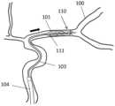
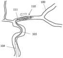
도 1a 내지 도 1e는 본 발명의 장치의 사용 방법을 도시한다. 가이드와이어(102) 및 마이크로카테터(103)가 종래에 공지된 기법을 이용하여 혈관계(100) 내에 삽입되고 폐색성 혈전(101)을 가로질러 전진된다. 마이크로카테터(103)가 폐색 혈전(101)에 대해 원위에 위치되는 경우, 가이드와이어(102)는 혈전 회수 장치(110)가 마이크로카테터를 통하여 전진되는 것을 허용하도록 혈관계(100)로부터 제거된다. 장치(110)는 장치의 원위 팁이 마이크로카테터(103)의 원위 단부에 도달할 때까지 접혀진 구성으로 전진된다. 장치의 원위 단부가 바람직하게는 혈전(101)의 원위에 위치되는 방식으로 혈전(101)을 가로질러 혈전 회수 장치를 전개하도록 장치(110)의 위치가 유지되면서 마이크로카테터는 후퇴된다(도 1b). 장치(110)는 세장형 근위 샤프트 부분(111)에 연결된 혈전 결합 부분(112)으로 이루어진다.1A to 1E show how to use the device of the present invention. A
장치(110)는 그가 근위 단부에서 또는 그의 길이를 따라서 폐색 혈전과 결합하도록 확장된다. 장치는 낮은 레벨들의 스캐폴딩(scaffolding)을 갖는 세그먼트들을 갖는데, 세그먼트들은 혈전을 압축하지 않고 혈전이 이들의 작은 반경방향 힘 영역 내로 돌출되는 것을 허용한다. 장치(110)는 원하는 경우에 혈전(101) 내에 일정 기간 동안 잠복(incubation)되는 것이 허용될 수 있다. 장치를 후퇴시키기 전에, 마이크로카테터는 원위방향으로 전진되어 작은 반경방향 힘 영역에 인접한 장치의 스트러트들 및 크라운들과 마이크로카테터의 팁 사이의 혈전의 일부를 핀치할 수 있다. 이러한 핀치는 접근 가이드 카테터 또는 도입기(introducer) 피복으로 다시 분리 및 보유 동안 혈전의 근위 단부의 추가 파지 및 제어를 제공한다(도 1e). 장치와 마이크로카테터 사이의 상대 장력은 혈전에 대한 핀치가 유지되는 것을 보장하기 위하여 분리 및 후퇴 동안 사용자에 의해 유지될 수 있다. 혈전을 핀치하기 위한 마이크로카테터 또는 중간 카테터의 사용이 본 발명과 함께 사용될 때 추가 이득을 부여하는 것으로 설명되지만, 본 명세서에서 설명되는 모든 실시예들은 또한 필요한 경우에 카테터 핀칭의 사용 없이 혈전을 분리 및 회수하는 데 사용될 수 있다.
혈관 내의 유동 정지(flow arrest)는 표준 기법에 따라 가이드 카테터 상의 벌룬(미도시)을 팽창시킴으로써 활용될 수 있다. 도 1e는 가이드 카테터(104) 내로의 회수 동안 장치와 결합된 혈전을 도시한다. 유동 폐색, 흡인 및 다른 표준 기법이 혈전 회수 과정 동안 사용될 수 있다. 장치(110)는 삽입 도구 내에 다시 로딩하기 전에 식염수 내에서 헹궈질 수 있고 부드럽게 세정될 수 있다. 장치(110)는, 필요한 경우, 폐색 혈전의 추가 세그먼트들 내에서 재전개되도록 마이크로카테터 내로 재도입될 수 있다.Flow arrest within a blood vessel can be exploited by inflating a balloon (not shown) on a guide catheter according to standard techniques. 1E shows a thrombus associated with the device during retrieval into the
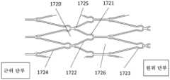
도 2a 내지 도 2c는 도 1a 내지 도 1e에 도시된 장치의 일 실시예의 근위 단부를 도시한다. 장치는 전형적으로 니티놀과 같은 "초탄성" 특성을 갖는 재료로 형성되고 튜브 또는 평탄한 시트의 원 재료로부터 레이저 절단될 수 있고 확장될 수 있다. 장치(130)의 자가 확장 섹션이 근위 세장형 샤프트(131)에 연결된다. 본 발명의 장치는, 혈전 핀치를 생성하고 장치(130)와 혈전(135) 사이에 추가 파지를 발생시키도록 설계된다. 장치(130)는 그가 낮은 스캐폴딩 및 작은 반경방향 힘의 영역들(132)이 산재되어 있는 우수한 혈전 매설을 제공하기 위하여 적절한 반경방향 힘을 갖는 스트러트들(134)의 링들로 이루어지도록 구성된다. 스트러트들의 링들 사이의 종방향 거리는 2mm 내지 8mm에서 가변될 수 있지만, 중간 뇌 동맥에서 사용하기 위한 바람직한 실시예에서, 종방향 간격은 3 내지 6 mm이다.Figures 2A-2C show the proximal end of one embodiment of the device shown in Figures 1A-1E. The devices are typically formed from materials with “superelastic” properties, such as nitinol, and can be laser cut and expanded from raw materials in tubes or flat sheets. The self-expanding section of
스트러트들(134)이 혈전의 일부 스캐폴딩을 매설 및 제공하지만, 낮은 스캐폴딩을 갖는 영역(132)은 혈전(136)이 이러한 영역 내로 돌출하는 것을 허용한다. 원하는 경우, 전형적으로 1 내지 5분의 잠복 시간 후에, 마이크로카테터(140)(장치 또는 다른 마이크로카테터를 도입하기 위하여 사용됨)는 마이크로카테터의 팁(144)과 장치(130)의 스트러트들 및 크라운(142) 사이의 돌출된 혈전(136)을 핀치하기 위하여 전진될 수 있다. 스트러트들(134)은 이러한 스트러트들의 자유롭게 확장된 직경이 폐색 혈전의 위치에서 표적 혈관의 직경의 30% 내지 150%로 가변될 수 있지만, 바람직한 실시예에서는 표적 혈관 직경의 50% 내지 100%이기 때문에 혈전 내에 우수한 매설을 달성한다. 도시된 실시예에서, 스트러트들(134)의 링들 사이의 연결 스트러트들(133)은 반경방향 힘 및 스캐폴딩을 최소화하기 위하여 스트러트의 중간 섹션을 향하여 감소된 직경을 갖고서 만곡된다. 이러한 특징부는 또한 도 3a 및 도 3b에서 알 수 있다.Although the
장치(130)에 대한 마이크로카테터(140)의 추가의 원위방향 전진은 카테터 팁(144)과 장치의 스트러트들(142) 사이의 혈전(141)을 추가로 압축하여 혈전에 대한 핀치(도 2c) 및 포획된 혈전 세그먼트(136)의 확보를 증가시킬 것이다. 사용자는 이러한 핀치를 저항으로 느껴서 마이크로카테터를 전진시키는 것을 멈출 수 있거나, 또는 그렇지 않으면 사용자는 장치와 마이크로카테터를 함께 후퇴시키기 전에 장치에 걸쳐 일정한 거리(예를 들어, 장치 길이의 30% 내지 50%)로 마이크로카테터를 전진시킬 수 있다. 장치(130)와 마이크로카테터(140) 사이의 상대 장력은 장치와 혈전 사이의 핀치가 악화되지 않다는 것을 보장하기 위하여 유지될 필요가 있다. 장치(130)와 마이크로카테터(140)를 함께 후퇴시킴으로써, 폐색 혈전은 분리되고 다시 접근 가이드 카테터 또는 도입기 피복 내로 후퇴될 수 있고 환자로부터 제거될 수 있다. 본 발명은 높은 피브린 함량(전형적으로 40% 초과의 피브린 함량)을 갖는 혈전 및 공지된 스텐트 회수기 설계를 사용하여 분리 및 회수하기 어려운 다른 혈전의 분리 및 후퇴에 특히 적합하고, 현재 혈전을 혈관계로부터 제거하기 위하여 다수의 통과를 필요로 할 수 있다. 본 발명은 또한 마이크로카테터(140)에 대해 여기서 설명된 바와 동일한 방식으로 중간 카테터를 전진시킴으로써 혈전 핀치를 생성할 수 있다.Further distal advancement of the
도 3a는 장치의 다른 실시예의 등각도를 도시한다. 이러한 구성에서, 장치의 매설 섹션은 셀들의 링(151)으로 이루어진다. 이러한 링(151)은 본 실시예에서 3개의 원주방향 셀들로 이루어진다. 원주방향 링 내의 셀들의 개수는 2 내지 5로 가변될 수 있지만, 바람직한 실시예에서는 3 또는 4개의 셀들이다. 도 2a 내지 도 2c에 도시된 장치에서와 같이, 장치의 매설 셀들 섹션 사이의 부분들(152)은 작은 반경방향 힘 및 낮은 레벨의 스캐폴딩을 갖는다. 낮은 레벨의 스캐폴딩은 장치 스트러트들과 이러한 영역(152) 내의 혈전 사이의 잠재적인 표면 접촉 영역을 최소화함으로써 달성된다. 본 실시예에서, 연결 스트러트들(153)은 혈전과의 스트러트 접촉력 및 접촉 면적을 추가로 감소시키기 위하여 중간 지점에서 장치의 중심선을 향하여 만곡된다. 이러한 작은 표면 접촉 면적 및 반경방향 힘은 장치가 폐색 혈전 내에서 전개되는 경우에 혈전이 장치의 이러한 섹션 내로 돌출되는 것을 허용한다. 이어서, 마이크로카테터 또는 중간 카테터에 의한 장치의 부분적인 재피복은 카테터의 팁과 셀들의 매설 링의 근위 스트러트들(154) 사이의 이러한 돌출된 혈전을 핀치할 수 있다.Figure 3a shows an isometric view of another embodiment of the device. In this configuration, the embedded section of the device consists of a
도 3b는 장치 길이에 대해 플로팅된 반경방향 힘의 대응하는 그래프와 함께 도 3a에 도시된 장치의 측면도를 도시한다. 점선들(155, 157)은 링들 사이의 섹션들(152)과 비교하여 혈전 내에 매설된 셀들의 링들이 어떻게 더 큰 반경방향 힘을 갖는지를 보여준다. 점선(156)은 이러한 섹션의 감소된 반경방향 힘을 나타낸다.FIG. 3B shows a side view of the device shown in FIG. 3A with a corresponding graph of radial force plotted against device length. Dashed lines 155, 157 show how the rings of cells embedded within the thrombus have greater radial forces compared to the
도 3c는 도 3a의 장치(150)와 유사한 본 발명 3개의 장치들의, 그들의 자유롭게 확장된 직경들의 50% 미만의 내강 내에 구속된 경우의, 외향 반경방향 힘 프로파일을 도시한다. 3개 모두는 전술된 대체적으로 사인 곡선인 패턴을 나타내지만, 반경방향 힘 피크들 및 저점(trough)들의 크기(또는 진폭)는 이들 장치의 길이를 따라서 가변된다. 프로파일(50)은 장치의 길이를 따라 테이퍼 업(taper up)되는 반경방향 힘 프로파일을 나타내는데, 제1 피크(51)의 반경방향 힘은 이후의 피크들(52 내지 54)의 반경방향 힘보다 작다. 프로파일(60)은 장치의 길이를 따라 테이퍼 다운(taper down)되는 반경방향 힘 프로파일을 나타내는데, 제1 피크(61)의 반경방향 힘은 이후의 피크들(62 내지 64)의 반경방향 힘보다 크다. 프로파일(70)은 장치의 길이를 따라 테이퍼 업 및 이어서 테이퍼 다운되는 반경방향 힘 프로파일을 나타내는데, 제1 피크(71)의 반경방향 힘은 제2 피크(72)의 반경방향 힘보다 작지만, 마지막 피크(74)의 반경방향 힘은 마지막에서 두 번째 피크(73)의 반경방향 힘보다 작다.Figure 3C shows the outward radial force profile of three devices of the invention, similar to
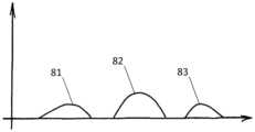
도 3d는 장치가 그의 자유롭게 확장된 직경의 50% 초과(예를 들어, 80%)의 내강 내에 대신 구속되면 반경방향 힘 프로파일(70)이 보여질 수 있는 것을 도시한다. 이러한 경우에, 장치가 도시된 3개의 피크들(81, 82, 83)의 어느 측의 영역들에서도 그를 구속하는 내강에 어떠한 외향 반경방향 힘도 인가하지 않는 것을 알게 된다. 따라서, 장치는 피크들 사이의 영역들 내의 혈전에 최소 압축을 인가하면서 피크들의 영역에서 혈전에 대한 그의 파지를 유지하여, 혈전을 후퇴시키는 데 필요한 힘을 최소화하는 것을 돕고 그에 따라서 성공적인 혈전 회수의 가능성을 증가시킨다.FIG. 3D shows what a
도 3c 및 도 3d는 또한 이들 3개의 상이한 장치들의 스트러트 요소들의 반경방향 압력을 나타낸다. 반경방향 압력은 그가 장치에 의해 인가되는 단위 면적당 힘을 지칭한다는 점에서 반경방향 힘과 상이하다. 따라서, 2개의 장치들이 주어진 영역에 걸쳐 동일한 반경방향 힘을 갖고 하나의 장치가 그러한 주어진 영역에서 다른 장치보다 작은 스트러트 표면적을 가지면, 더 작은 스트러트 표면적을 갖는 장치는 더 큰 반경방향 압력을 인가할 것이다. 이는 반경방향 압력이 스트러트가 그 자신을 혈전 물질 내로 매설할 수 있게 하는 것이기 때문에 혈전 파지에 매우 중요하다 - 부드러운 모래 위에 서 있는 경우에 스틸레토 힐(stiletto heel)은 모래 내로 깊게 빠질 것이지만 코끼리 발은 그렇게 깊게 빠지지 않을 것이라는 스틸레토 힐과 코끼리 발 사이의 차이와 다소 유사하다. 따라서, 주어진 레벨의 반경방향 힘의 경우, 장치의 반경방향 압력은, 스트러트 폭 또는 스트러트들의 개수를 감소시킴으로써 행해질 수 있는 스트러트 표면적을 감소시킴으로써 증가될 수 있다.Figures 3c and 3d also show the radial pressure of the strut elements of these three different devices. Radial pressure differs from radial force in that it refers to the force per unit area applied by the device. Therefore, if two devices have the same radial force over a given area and one device has a smaller strut surface area than the other device in that given area, the device with the smaller strut surface area will apply a greater radial pressure. . This is very important in thrombus arrest because radial pressure is what allows the strut to bury itself into the thrombus material - if you are standing on soft sand your stiletto heel will sink deep into the sand, but an elephant's foot will not. It's somewhat similar to the difference between a stiletto heel that won't sink in and an elephant foot. Therefore, for a given level of radial force, the radial pressure of the device can be increased by reducing the strut surface area, which can be done by reducing the strut width or the number of struts.
혈전 파지에서 이러한 증가된 반경방향 압력의 유효성은 혈관의 종축에 대한 스트러트들의 각도를 최대화함으로써 추가로 증가될 수 있다. 스트러트의 각도가 크면 클수록, 혈전을 활주하여 지나치는 것보다 오히려 그를 파지하는 스트러트의 능력은 더 커진다. 이상적으로, 스트러트는 최적의 파지를 위해 혈관 축과 90도의 각도에 접근할 것이지만 이는 실제로 많은 이유로 달성하기 어려울 수 있다. 이에 대한 한 가지 주요 이유는 장치가 전형적으로, 초기에 혈전 아래에서 전개되는 경우에 그의 자유롭게 확장된 직경의 단지 일부분으로만 확장된다는 사실이다. 이는 장치가 더 큰 더 근위의 혈관 내로 후퇴됨에 따라 그가 혈전에 대한 그의 파지를 유지할 수 있고 혈관 벽과 접촉 상태로 남아 있을 수 있도록 장치가 후퇴됨에 따라 장치가 큰 직경으로 확장될 수 있는 것이 유리하기 때문이다. 본 발명자들은 이러한 문제에 대한 효과적인 해법, 즉 본 발명 전체를 통하여 다양한 도면들, 예를 들어 도 7a에 도시된 바와 같은 2단계 직경의 장치를 발견하였다. 근위의 더 작은 직경이 가파른 개방 각으로 확실한 파지를 위하여 혈전 내에 스트러트들을 단단히 매설하기 위하여 사용될 수 있는 한편, 더 큰 직경의 원위 섹션은 혈관 벽과의 접촉 상태를 유지하도록 그리고 그가 더 큰 혈관 내로 후퇴됨에 따라 혈전의 원위방향 이동으로부터 보호하도록 확장될 수 있다. 이러한 구성은 근위 섹션의 스트러트 각도가 혈관 축에 대해 30도 초과이거나, 바람직하게는 45도 초과이거나, 심지어 더 바람직하게는 60도만큼 클 수 있게 한다. 도 7d는 이러한 점을 더 상세히 예시한다.The effectiveness of this increased radial pressure in thrombus gripping can be further increased by maximizing the angle of the struts relative to the longitudinal axis of the blood vessel. The greater the angle of the strut, the greater the ability of the strut to grip the thrombus rather than glide it past. Ideally, the struts would approach an angle of 90 degrees with the vessel axis for optimal grip, but this may be difficult to achieve in practice for many reasons. One major reason for this is the fact that the device typically expands only a fraction of its freely expanded diameter when initially deployed beneath a thrombus. This is advantageous for the device to be able to expand to a large diameter as it is retracted so that it can maintain its grip on the thrombus and remain in contact with the vessel wall as it is retracted into the larger, more proximal vessel. Because. The inventors have found an effective solution to this problem, namely a two-stage diameter device as shown in the various figures throughout the invention, for example in Figure 7a. The proximal, smaller diameter can be used to firmly embed the struts within the thrombus for secure grip with a steep opening angle, while the larger diameter, distal section maintains contact with the vessel wall and allows it to retract into the larger vessel. As it becomes available, it can be expanded to protect against distal movement of the blood clot. This configuration allows the strut angle of the proximal section to be greater than 30 degrees, preferably greater than 45 degrees, or even more preferably as high as 60 degrees relative to the vessel axis. Figure 7d illustrates this point in more detail.
도 4a 내지 도 4e는 평탄한 시트로 형성된 장치의 다른 실시예를 도시한다. 도 4a는 본 실시예에서 사인 곡선 에지들(165)에 의해 경계가 지어지고 크로스 스트러트들(164)에 의해 연결되는 셀들(162)의 2개의 행들로 형성된 장치(160)의 평면도를 도시한다. 장치는 근위 샤프트(161)에 연결된다. 도 4b는 혈관(170) 내에 위치되는 폐색 혈전(174) 내에서 전개된 장치(160)의 등각도를 도시한다. 혈관(170)의 절개도가 명료성을 위하여 제공되었다. 마이크로카테터(172)는 근위 샤프트 상에 위치되고 마이크로카테터의 팁이 장치의 혈전 결합 섹션과 샤프트 사이의 조인트에 위치된 것으로 도시되어 있다. 혈전(174)이 장치(160)와 접촉하는 경우, 혈전의 일부들(171)은 셀들을 통하여 돌출된다. 도 4c는 혈전(183) 및 장치(182)를 포함하는 혈관(180)의 단면도를 도시한다. 이러한 도면은 장치의 셀들을 통하여 돌출되는 혈전(181)을 예시한다.Figures 4a-4e show another embodiment of a device formed from a flat sheet. Figure 4a shows a top view of a
도 4d는 마이크로카테터(200)가 장치를 절개된 혈관(204) 내에 부분적으로 재피복하기 위하여 전진됨에 따라 혈전이 어떻게 핀치되는지를 도시하는 장치(206)의 근위 단부의 확대도이다. 혈전의 돌출 부분(210)은 장치의 스트러트들과 마이크로카테터(200) 사이에 포획된다. 도 4e는 장치(206)와 마이크로카테터(200)가 동시에 후퇴되어, 혈전의 돌출된 부분(211)에 대한 핀치된 파지로 인해, 혈전의 몸체(205)를 혈관(204)으로부터 분리하는 것을 도시한다.4D is an enlarged view of the proximal end of the
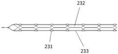
도 5a 내지 도 5d는 본 발명의 장치의 대안의 관형 실시예를 도시한다. 도 5a 내지 도 5d는 장치(230)의 측면도, 단부도, 평면도, 및 등각도를 도시한다. 이러한 장치는 작은 반경방향 힘 세그먼트들(232)과 매설 스트러트들(231)의 교호하는 링들을, 그의 길이를 따라서, 갖는다. 바람직한 실시예는 혈전 내의 최적의 매설을 위하여 반경방향 패턴으로 4개 내지 8개의 스트러트들을 포함한다. 본 실시예의 섹션(232)의 연결 스트러트들(233)은 장치가 구불구불한 해부학적 구조를 통하여 전달될 수 있는 것을 보장하도록 최적의 압입성(pushability)을 위해 직선이다.Figures 5a-5d show an alternative tubular embodiment of the device of the invention. 5A-5D show side, end, top, and isometric views of
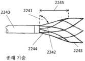
도 6a 내지 도 6d는 본 발명의 다른 실시예를 도시한다. 도 6a 내지 도 6d는 장치(240)의 측면도, 평면도, 단부도, 및 등각도를 도시한다. 이러한 장치는 작은 반경방향 힘 세그먼트들(242)과 매설 셀들(241)의 교호하는 링들을 갖는다. 바람직한 실시예는 혈전 내의 최적의 매설을 위하여 반경방향 패턴으로 2개 내지 4개의 셀들을 포함한다. 본 실시예에서 스트러트들의 링 대신 셀들의 링을 사용함으로써, 마이크로카테터가 전진함에 따라 그에 의해 스트러트들의 더 근위의 링(245)이 감싸이는 경우에도 각각의 세그먼트 내의 스트러트들의 원위의 링(244)이 더 오랫동안 확장된 상태로 유지됨에 따라 혈전 핀칭을 개선시킬 수 있다. 이는 혈전 내의 스트러트 매설을 더 오랫동안 유지하여 스트러트들과 마이크로카테터 사이의 혈전의 핀치를 개선한다.6A to 6D show another embodiment of the present invention. 6A-6D show side, top, end, and isometric views of
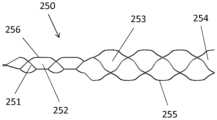
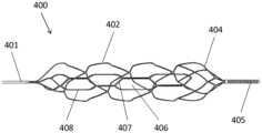
도 7a 내지 도 7d는 외부 케이지와 내부 구성요소의 조립체로 이루어진 실시예를 도시한다. 본 실시예에서, 외부 구성요소(250)의 근위 부분(256)은 도 1 및 도 2에 대해 설명된 바와 동일한 방식으로 혈전을 핀치하도록 설계되고, 교호하는, 혈전 내에 매설하기 위한 셀들의 세그먼트들(251)과 작은 반경방향 힘 및 낮은 스캐폴딩의 세그먼트들(252)을 포함한다. 외부 구성요소의 이러한 근위 부분(256)은, 장치 및 혈전의 접근 가이드 카테터 또는 도입기 피복 내로의 후퇴 전에 혈전이 내경동맥 내의 더 큰 혈관 직경 내로 회수됨에 따라 추가 혈전 보유를 위하여 증가된 직경의 더 큰 셀들(253)을 갖는 몸체 섹션(255)에 결합된다. 몸체 섹션(255) 직경 대 근위 섹션 직경의 비는 1.5:1 내지 4:1로 가변될 수 있고, 바람직한 실시예에서는 2:1 내지 3:1이다.7A-7D show an embodiment consisting of an assembly of an external cage and internal components. In this embodiment, the
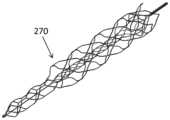
도 7b는 조립체의 내부 구성요소(260)를 도시한다. 이러한 구성요소는 몸체 섹션(262)을 샤프트(미도시)에 연결하는 세장형 근위 스트러트(261)를 포함한다. 구성요소(260)는 또한 단편 보호 구조물(263) 및 원위 비외상성 팁(264)을 포함한다. 도 7c는 2개의 구성요소들이 어떻게 조립체(270)에 정렬되는지를 도시한다. 세장형 근위 스트러트(273)는 작은 반경방향 힘 세그먼트들 내로의 혈전 돌출에 대한 제한이 최소가 되도록 외부 케이지(277)의 근위 부분 아래 위치된다. 내부 구성요소(274)의 몸체 섹션은 외부 구성요소(271)의 몸체 섹션 내에 위치되고, 혈전을 가로지른 압력 구배를 약화시켜 유동 복원을 제공하도록 유동 채널을 제공한다. 원위 단편 보호 구조물(275)은 개방 단부(272)를 갖는 외부 케이지의 단부 내측에 안착하여 혈전 조각 및 색전의 손실로부터 보호한다. 도 7d는 이러한 조립체(270)의 등각도를 도시한다.Figure 7b shows the
도 7e는 혈관(259) 내의 혈전(258) 내에서 전개된 장치(250)를 도시하는데, 이는 도 7a의 혈전 결합 요소(250)의 설계와 같은 단차형 직경 설계의 주요 이점을 예시한다. 근위 섹션의 스트러트들(256)의 비교적 큰 반경방향 힘 및 반경방향 압력은 그 섹션의 스트러트들(251)이 혈전 내로 깊게 매설되게 하여, 마이크로카테터(미도시)의 전진에 의해 이후에 셀들(252) 내에 핀치될 수 있는 혈전 돌출부(257)를 생성한다. 더욱이, 근위 섹션(256)의 더 작은 자유롭게 확장된 직경은 이러한 섹션의 스트러트들(251)이 원위 섹션(255)의 스트러트들보다 매우 더 가파른 각도로 경사지는 것을 의미하는데, 이는 확실한 후퇴를 위해 이들이 혈전을 더욱 더 효과적으로 파지할 수 있게 한다. 도 3d 및 도 3e와 관련한 설명은 이들 스트러트 각도의 중요성을 더 상세히 설명한다.FIG. 7E shows the
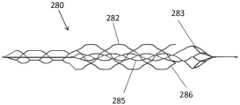
도 8은 내부 구성요소(285)에 연결된 단편 보호 구조물(283)이 외부 케이지(282)의 단부의 원위에 위치되는, 도 7에 도시된 조립체의 다른 구성(280)을 도시한다. 외부 케이지(286)의 단부와 단편 보호 구조물(283) 사이에 갭(gap)이 존재하는 것을 보장하면, 특히 장치가 구불구불한 혈관 내에서 후퇴될 때 조각 보호 성능을 개선시킬 수 있다. 이는 또한 장치가 카테터 내로 회수될 때 이로울 수 있는데, 이는 외부 케이지가 완전히 회수될 때 조각 보호 구역(283)이 계속해서 완전히 확장될 것이고 보호를 제공할 것이기 때문이다.FIG. 8 shows another
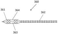
도 9는, 카테터가 원위방향으로 전진되는 경우, 구성요소의 근위 부분(335)이 도 7에서 설명된 바와 같이 혈전을 핀치하도록 설계된 다른 외부 케이지 구성(330)의 측면도이다. 이러한 구성에서, 구성요소(330)는 또한 회수 중에 혈전 보유를 위한 몸체 섹션(332) 및 또한 원위 조각 구역(334)을 포함한다. 도 10은 도 9에서 설명된 외부 케이지(342)와 내부 채널(344)의 조립체(340)를 도시한다. 이러한 조립체(340) 내의 내부 채널(344)은 근위 섹션(341) 아래를 포함하여 외부 케이지(342)의 전체 길이로 이어진다.FIG. 9 is a side view of another
도 11은 몸체 섹션(362), 및 혈전 돌출 및 혈전 핀칭을 촉진하기 위하여 낮은 스캐폴드형 영역들(363)과 매설 셀들(361)의 교호하는 세그먼트들을 포함하는 근위 섹션(364)으로 이루어진 내부 구성요소(360)를 도시한다. 도 12는 이러한 내부 채널 설계(373)가 어떻게 조립체(370) 내에서 외부 케이지(372)와 일체화될 수 있는지를 도시한다. 외부 케이지(372)는 내부 구성요소의 근위 섹션(371)과 결합하는 혈전에 대한 어떠한 폐색도 최소화하도록 연장된 근위 스트러트들(375)을 갖는다.11 shows an internal configuration consisting of a
도 13은 외부 케이지(402)와 내부 채널(408)의 조립체로 이루어진 본 발명의 다른 실시예(400)를 도시한다. 이들 2개의 구성요소들은 근위 샤프트(401) 및 방사선 불투과성 원위 팁(405)에 연결된다. 본 실시예에서, 내부 채널(408)은, 낮은 스트러트 밀도 또는 스캐폴딩(406)의 영역들에 인접한, 혈전 내의 깊은 매설을 위한 스트러트들(407)의 교호하는 링들을 가짐으로써 본 명세서 내의 다른 곳에서 설명된 바와 같이 혈전 핀칭을 용이하게 하도록 설계된다. 이러한 내부 구성요소(408)가 외부 케이지(402)의 내측에 위치됨에 따라, 외부 케이지의 스트러트들이 내부 채널(408) 내의 혈전 매설 및 돌출을 폐색하기 위한 잠재력이 존재한다. 이러한 문제를 없애기 위하여, 외부 케이지(402)는, 외부 케이지가 자유롭게 확장된 내부 채널과 동일한 직경으로 부분적으로 확장되는 경우, 외부 케이지의 스트러트들이 내부 채널(408)의 스트러트들과 정렬하도록 설계된다.13 shows another
도 14a 및 도 14b는 도 13에 도시된 외부 케이지의 세그먼트(420)를 도시한다. 세그먼트(420)는 도 14a에 내부 채널의 자유롭게 확장된 직경보다 크지만 외부 케이지의 자유롭게 확장된 직경 미만인 직경으로 확장된 상태로 도시되어 있다. 스트러트(421)의 `도그 레그(dog-leg)' 형상은 이미지에서 알 수 있고, 이러한 형상의 스트러트는 셀들(425)을 형성하도록 원주 둘레에 그리고 길이를 따라서 반복된다. 도 14b는 스트러트 형상이 도시된 바와 같이 더 긴 세그먼트(424)에 각도(A)로 연결된 짧은 세그먼트(423)로 어떻게 이루어지는지를 도시한다. 이러한 각도는 20° 내지 90°로 가변될 수 있고, 바람직한 실시예에서는 30° 내지 60°이다. 스트러트의 짧은 세그먼트(423)는 또한 더 긴 세그먼트(424)와 비교하여 증가된 스트러트 폭을 가질 수 있다. 이러한 구성에서, 짧은 스트러트 세그먼트(423)는 더 긴 스트러트 세그먼트(424)보다 높은 확장력을 갖고 그러므로 이는 잠재적인 확장을 가질 것이고 크라운(426)은 크라운(427)이 확장되기 전에 개방될 것이다. 이는 스트러트들(424) 및 크라운(427)이 확장되기 전에 스트러트들(423) 및 크라운(426)이 완전히 확장되는 2단계의 확장 과정을 외부 케이지에 부여한다. 이러한 2단계 확장 과정은 또한 제1 단계 확장이 완료된 경우 감소되는 반경방향 힘 프로파일을 야기한다. 이러한 스트러트 구성은 제1 단계 확장 직경 이상의 직경을 갖는 니티놀 튜브로부터 이러한 스트러트 프로파일을 레이저 절단함으로써 생성될 수 있다. 대안적으로, 부품은 열 고정 동안 이러한 형상으로 구속된 더 작은 튜브 및 스트러트들로부터 레이저 절단될 수 있다.Figures 14A and 14B show a
도 15는 도 14와 동일한 외부 케이지 세그먼트를 도시한다. 그러나, 본 이미지에서, 세그먼트(430)는 자유롭게 확장된 내부 채널과 동일한 직경에 있다. 이는 스트러트들(432)이 완전히 확장되지만 스트러트들(434)은 여전히 접혀있는 경우에 제1 단계 확장 단계의 말미와 동일한 직경이다. 도 16은 도 14 및 도 15에 도시된 외부 케이지 세그먼트와 정렬된 내부 채널의 세그먼트를 도시한다. 도 13에서 논의된 바와 같이, 이러한 세그먼트(440)는 스트러트들(442)의 링들 및 작은 반경방향 힘 및 스트러트 밀도의 영역들(444)을 포함한다.Figure 15 shows the same outer cage segment as Figure 14. However, in this image,
도 17은 내부 채널 세그먼트(453)(도 16에서 설명)와 중첩된 외부 케이지 세그먼트(452)(도 15에서 설명)를 도시한다. 이러한 설계의 이득은 세그먼트들 둘 모두의 스트러트들이 도시된 바와 같이 완전히 정렬되는 것이고, 따라서 혈전 내에 매설되는 스트러트 섹션(450)에 대해 어떠한 폐색도 없다. 유사하게는, 셀 영역(451) 내로 돌출된 혈전에 대한 어떠한 폐색도 없어서, 그에 의해 마이크로카테터가 원위방향으로 전진되는 경우 핀치를 용이하게 한다. 더욱이, 장치가 가이드 카테터 또는 피복을 향하여 근위방향으로 후퇴됨에 따라, 외부 케이지는 계속 확장될 수 있고 혈관 직경이 증가하는 경우에도 혈전과 접촉을 유지한다.Figure 17 shows an outer cage segment 452 (illustrated in Figure 15) overlapped with an inner channel segment 453 (illustrated in Figure 16). The benefit of this design is that the struts of both segments are perfectly aligned as shown, so there is no obstruction to the
도 18은 혈전 핀칭에 이로운 셀 패턴(470)을 도시한다. 이러한 패턴(470)은 관형 또는 평탄형 장치 구성으로 포함될 수 있다. 혈관계 내의 폐색 혈전을 가로질러 전개되는 경우, 큰 셀 영역(473) 내에서 혈전 돌출이 일어난다. 적합한 잠복 시간 후에, 마이크로카테터는 장치를 부분적으로 재피복하기 위하여 근위 측(472)으로부터 전진될 수 있다. 마이크로카테터가 셀(473) 내로 돌출된 혈전과 접촉하는 경우, 그는 혈전을 셀 내에서 스트러트들(471) 사이의 영역(474) 내로 원위방향으로 이동시키도록 힘을 가한다. 협소 스트러트들은 포획된 혈전을 크라운(475)을 향하여 보내서 카테터 팁과 장치 사이의 혈전에 대한 개선된 핀치를 생성한다.Figure 18 shows a
도 19는 평행하게 연결된 다수의 관형 구성요소들의 조립체(470)로 이루어진 본 발명의 구성을 도시한다. 도시된 구성에서, 2개의 구성요소들(472, 473)은 스트러트(474)에 의해 근위 단부에서 연결되고 이어서 근위 샤프트(471)에 연결된다. 여기에 도시된 구성요소들(472, 473) 둘 모두는 도 3 및 도 6에서 설명된 실시예들과 유사한다. 이러한 구성요소들의 정렬은 본 이미지에 도시된 바와 같이 엇갈려 있을 수 있고 구성요소들은 길이를 따라서 서로의 주변에 구부러져 있을 수 있다. 2개 초과의 구성요소들이 이러한 방식으로 서로 연결될 수 있고 상이한 구성요소들은 상이한 직경들을 가질 수 있거나 또는 길이를 따라서 테이퍼질 수 있다. 이러한 구성요소들의 조립체는 장치가 마이크로카테터 또는 중간 카테터에 의해 부분적으로 재피복되는 경우에 혈전 핀칭 및 파지를 개선할 가능성을 갖는다.Figure 19 shows a configuration of the invention consisting of an
도 20a는 관형 구성요소(480)가 나선형 또는 나사형 형상(482)으로 형성되고 근위 샤프트(481)에 연결되는 장치의 구성을 도시한다. 구성요소(483)의 절단 패턴은 도 3 및 도 6에서 설명된 바와 같이 혈전 매설 및 파지를 촉진하도록 설계된다. 그러나, 이러한 구성에서, 구성요소의 중심선은 도 20b에 도시된 것과 같은 나선형 트랙을 따르는데, 여기서 트랙(491)은 실린더형 맨드릴(490)의 표면을 따른다.FIG. 20A shows the configuration of the device in which a
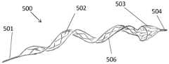
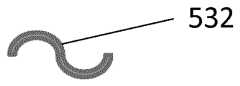
도 21에 도시된 장치의 다른 실시예에서, 평탄한 장치(500)가, 장치의 중심선이 또한 이 경우에 나선형 경로를 형성하도록 형성된다. 이러한 장치는 요구되는 스트러트 패턴(502)을 튜브로부터 레이저 절단함으로써 또는 평탄한 시트를 절단하고 이어서 열 고정 전에 실린더 둘레에 평탄한 부품을 둘러쌈으로써 형성될 수 있다. 그러므로, 장치는 실린더 둘레에 넓은 리본을 둘러싸는 것과 유사한 형상을 갖는다. 이러한 장치가 폐색 혈전을 가로질러 전개되는 경우, 혈전은 낮은 스트러트 밀도의 영역 내로 그러나 또한 나선형 코일들의 중심 내강 내로 돌출될 수 있다. 장치 후퇴 시 이는 혈전 파지 및 분리 성능을 개선할 수 있고 장치가 혈전과 접촉할 때까지 마이크로카테터 또는 중간 카테터가 장치에 걸쳐 원위방향으로 전진되는 경우에 혈전 핀칭을 또한 용이하게 할 수 있다. 도시된 실시예(500)는 장치의 몸체 부분(506) 내에 평탄한 단면을 갖는다. 나선형 몸체 섹션은 근위 샤프트(501)에 그리고 원위 팁(504)을 갖는 원위 단편 보호 구조물(503)에 연결된다. 도 22는 몸체 세그먼트(522)에 대한 만곡된 또는 윤곽형성된 단면 형상을 제외하고는 도 21과 유사한 다른 장치 실시예(520)를 도시한다. 도 23a 내지 도 23c는 본 발명의 이러한 구성에 포함될 수 있는 단면 형상들의 상이한 예들을 도시한다. 도 23a는 평탄한 단면(531)을 도시하고, 도 23b는 'S' 형상의 단면(532)을 도시하고, 도 23c는 만곡된 단면(533)을 도시한다.In another embodiment of the device shown in FIG. 21 , the
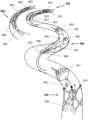
도 24a는 도 23c에 도시된 것과 유사한 만곡된 단면을 갖는 장치(550)의 다른 나선형 구성을 도시한다. 레이저 절단된 또는 와이어 형성된 혈전 결합 섹션(553)은 근위 샤프트(551)에 연결된다. 혈전을 핀치하고 도 1에서 설명된 바와 같이 혈전에 대한 개선된 파지를 발생시키도록 마이크로카테터가 이러한 장치와 함께 사용될 수 있다. 마이크로카테터 또는 중간 카테터가 혈전을 핀치하도록 장치에 걸쳐 전진되는 경우, 이는 혈관의 중심선을 따를 수 있거나 또는 그렇지 않으면 이는 도 24b에 도시된 바와 같이 장치의 중심선을 따르고 나선형 트랙을 따를 수 있다. 카테터(561)가 재피복 동안 혈관의 중심선(562)을 따르는 경우에, 이는 나선형 코일 내에서 내강 공간(564) 내의 혈전의 우수한 핀칭을 발생시킬 수 있다. 대안적으로, 카테터(561)가 도시된 바와 같이 장치의 중심선(563)을 따르는 경우, 이는 절단 패턴의 셀들(560) 내에서 혈전의 우수한 핀칭을 발생시킬 수 있다. 도 25는 이중 나선 유형 구조를 형성하도록 2개의 나선형 구성요소들(583, 584)로 구성된 장치(580)의 실시예를 도시한다.FIG. 24A shows another helical configuration of
도 26은 도 7에서 설명된 것과 유사한, 장치의 근위 부분(601)이 필요한 경우에 혈전 핀칭을 용이하게 하도록 설계되는 본 발명의 다른 실시예(600)를 도시한다. 몸체 섹션(604)은 또한 도 7에서 설명된 것과 유사하지만, 본 실시예에서는, 근위 섹션과 몸체 섹션 사이의 연결부(603)가 장력 하에서 신장될 수 있다. 이는 장치에 의한 분리 중에 혈전의 신축을 용이하게 한다. 혈전의 근위 단부가 장치의 근위 부분(601)에 대해 핀치 및 구속되는 한편 혈전의 원위 단부는 몸체 섹션(604) 상에 위치될 것이다. 장치가 후퇴되는 경우, 근위 단부(601)가 먼저 이동하여 혈전의 근위 단부를 당길 것이다. 혈전의 원위 단부가 혈관 내에 들러붙은 경우, 장치의 몸체 섹션은 정지 상태로 유지될 것이고 커넥터(603)는 신장될 것이다. 이는 또한 혈전을 신장시켜 이를 혈관 벽으로부터 박리하고 분리력을 감소시킬 것이다. 커넥터(603) 내의 장력이 혈전의 원위 섹션의 분리력과 동일한 경우, 혈전의 나머지는 이동하기 시작할 것이다. 본 실시예에서, 신장형 커넥터(603)는 코일 스프링으로 형성되지만, 다른 실시예에서, 이러한 신장형 요소는 외부 케이지의 절단 패턴의 일부를 형성할 수 있다.Figure 26 shows another
도 27a 및 도 27b는 장치의 다른 실시예를 도시한다. 도 27a는 자유롭게 확장된 구성 상태에 있는 장치(700)를 도시한다. 본 발명의 이러한 형태에서, 외부 케이지의 근위 부분(701)은 혈전 매설 및 혈전 돌출을 촉진하도록 구성되어 혈전 핀칭을 용이하게 한다. 외부 케이지의 몸체 섹션(702)은 근위 섹션과 비교하여 증가된 직경을 가져서, 장치가 혈관계 내의 만곡부 및 분지부를 지나서 후퇴됨에 따라 우수한 혈전 보유를 보장한다. 외부 케이지는 방사선 불투과성 마커들(703)이 원위 크라운들 상에 도시된 개방 원위 단부를 갖는다. 이러한 조립체의 내부 구성요소는 단편 보호 구조물(705)을 근위 조인트(708)와 연결하는 와이어(706)로 이루어진다. 자유롭게 확장된 구성에서, 외부 케이지의 원위 스트러트들(703)과 단편 보호 구조물의 리딩(leading) 에지(707) 사이에 뚜렷한 갭이 존재한다. 이러한 갭은 1mm 내지 20mm로 가변될 수 있고, 바람직한 실시예에서는 5 내지 10 mm 범위일 것이다.Figures 27a and 27b show another embodiment of the device. Figure 27A shows
도 27b는, 본 이미지에서 장치(750)가 폐색 혈전의 위치에서 표적 혈관의 직경으로 있는 것을 제외하고는 도 27a와 동일한 장치를 도시한다. 이러한 직경으로, 단편 보호 구조물(755)의 리딩 에지(757)는 외부 케이지(752) 내측에 그리고 원위 크라운들(753)의 근위에 위치된다. 외부 케이지(752)에 대한 단편 보호 구조물(755)의 위치의 이러한 변화는 자유롭게 확장된 구성에서 그리고 감소된 직경들에서 외부 케이지(752)의 길이 차이로 인한 것이다. 단편 보호 구조물을 작은 직경들로 외부 케이지 내측에 위치시킴으로써 장치 전개를 위하여 혈전의 원위에 필요한 파킹(parking) 공간을 최소화한다. 더욱이, 큰 혈관 내에서 장치 후퇴 동안 그리고 가이드 또는 중간 카테터 내로의 회수 동안 외부 케이지(752)의 원위에 단편 보호 구조물(755)을 위치시킴으로써 조각 보호의 효과를 개선한다.FIG. 27B shows the same device as FIG. 27A except that in this
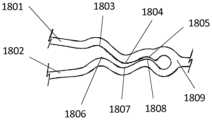
도 28은 도 27에서 설명된 장치 실시예의 사용 방법을 보여준다. 장치(800)는 표준 개입 기법(standard interventional technique)을 사용하여 혈전(803)을 가로질러 전개되고, 장치의 원위 단부(802) 및 단편 보호 구조물(801)이 혈전(803)의 원위에 위치되도록 위치된다. 장치(800)는 또한 혈전 핀치 부분(804)을 포함하고 세장형 근위 샤프트 부분(805)에 연결된다.Figure 28 shows a method of use of the device embodiment described in Figure 27.
장치 이미지(850)는 마이크로카테터(855)가 혈전(853)과 장치의 근위 부분(854) 사이에 핀치를 발생시키도록 전진된 후의 혈관 내의 장치를 도시한다. 표적 혈관 위치의 이러한 직경에서, 원위 단편 보호 구조물(851)은 부분적으로 외부 케이지(852) 내측에 있다.
장치 이미지(900)는 더 큰 직경 혈관 내로 다시 후퇴된 경우의 장치를 도시한다. 혈관 직경이 증가함에 따라, 외부 케이지(901)의 직경은 또한 증가하고 외부 케이지 길이는 짧아진다. 이는 단편 보호 구조물의 근위 에지(902)와 외부 케이지의 원위 단부(905) 사이에 갭을 생성한다. 이는 분리 및 회수 과정 동안 해방된 몇몇 조각들 또는 색전들(904)의 캡처를 용이하게 한다. 혈전(906)은 마이크로카테터(907)의 원위 팁과 장치(908) 사이에서 핀치된 상태로 계속 유지된다.
장치 이미지(950)는 또한, 그가 회수 과정 동안 혈전 몸체(956)로부터 방출된 혈전 조각들(954, 953)을 캡처함에 따른 단편 보호 구조물(951)의 유효성을 도시한다.
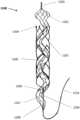
도 29에 도시된 장치(1000)는 관형 구성요소(1001)가 나선형 또는 나사형 구성으로 형성되고 근위 샤프트(1002)에 연결되는 도 20a 및 도 20b에 도시된 장치의 다른 실시예이다. 이러한 구성에서, 구성요소의 중심선은 도 20b에 도시된 바와 같이 테이퍼형이거나 실린더형인 맨드릴의 표면을 따르는 나선형 트랙을 형성한다. 관형 구성요소의 직경은 0.5 내지 8.0 mm로 가변될 수 있고, 바람직한 실시예에서는 1.0 내지 4.0 mm 범위이다. 나선 트랙을 따르는 실린더형 맨드릴의 직경은 1.0 내지 10.0 mm로 가변될 수 있고, 바람직한 실시예에서는 2.0 내지 7.0 mm 범위이다. 나선의 피치는 3.0 내지 30mm로 가변될 수 있고, 바람직한 실시예에서는 10.0mm 내지 20.0mm 범위이다.The
이러한 장치의 나선형 구성은 장치가 직선형 구성의 경우보다 혈전과 더 많이 결합함에 따라 혈전 분리에 대한 성능 이득을 제공한다. 혈전은 셀들 내에 그리고 장치의 스트러트들 사이에 깊게 매설되어 혈전에 대한 장치의 파지를 개선한다. 이는 장치의 일부분들을 혈관의 표면으로부터 멀리 그리고 혈전의 몸체 내에 위치시키는 나선형 형상으로 인해 일어난다. 이는 나사형 장치(1051)가 신경 혈관들(1050) 내의 혈전(1052) 내에서 전개된 도 30에 도시되어 있다. 장치(1051)는, 그를 마이크로카테터(1053)를 통하여 전달하고 이어서 마이크로카테터를 후퇴시킴으로써, 스텐트 회수기를 전개하기 위한 표준 절차에 따라 전개된다. 한 가지 사용 방법에서, 장치(1051)는 혈전(1052)을 분리하고 이를 접근 카테터(1054) 내로 회수하기 위하여 직접 후퇴될 수 있다. 그 절차 동안 흡인이 활용될 수 있고 유동 정지가 접근 카테터(1054) 상에서 벌룬(1055)을 팽창시킴으로써 제공될 수 있다. 대안적으로, 혈전 내의 장치(1051)의 전개 후에, 마이크로카테터(1053)는 다시 전진되어 장치(1051)를 부분적으로 재피복할 수 있고 마이크로카테터의 원위 팁과 장치(1051)의 스트러트들 및 크라운들 사이의 혈전에 대한 핀치를 발생시킬 수 있는데, 이는 본 명세서 내의 다른 곳에서 설명된 바와 같다. 이어서, 장치, 마이크로카테터 및 혈전은, 필요한 경우에, 유동 정지 및 흡인을 이용하여, 하나의 단위로서 접근 카테터 내로 후퇴될 수 있다.The helical configuration of these devices provides a performance gain for clot separation as the device engages more clots than would be the case in a straight configuration. The clot is embedded deeply within the cells and between the struts of the device, improving the device's grip on the clot. This happens due to the spiral shape that positions parts of the device away from the surface of the blood vessel and within the body of the thrombus. This is shown in FIG. 30 where the screw-
나선형 또는 코르크 스크류 구성으로 장치 내에 매설되는 혈전의 증가된 깊이는 까다로운 혈관 비틀림부 내의 그리고 혈관 분기부 - 도 31에 도시된 바와 같이 분기부의 유효 직경(D4)이 근위 혈관의 직경(D1) 또는 원위 혈관의 직경(D2, D3)보다 큼 - 내의 혈전에 대한 핀치를 얻는 데 특히 유용하다. 이는 도 32a 및 도 32b에 추가로 도시되는데, 여기서 도 32a는 혈관(1070) 내의 혈전(1072) 내에서 전개된 직선 관형 구성요소(1071)를 도시한다. 도 32b는 관형 구성요소(1083)(도 32a의 구성요소(1071)와 동일한 직경을 가짐)가 나선형 구성으로 형성된 경우에 혈전(1082) 내의 개선된 결합 및 매설을 도시한다. 나선형 구성은 장치(1083)가 혈전 내에서 결합하는 깊이 및 또한 혈전과 접촉 상태에 있는 장치의 표면적을 증가시킨다.The increased depth of the thrombus embedded within the device in a spiral or corkscrew configuration allows the effective diameter of the bifurcation (D4) to be greater than or equal to the diameter of the proximal vessel (D1) or distal to that of the proximal vessel, as shown in Figure 31. Larger than the diameter of the blood vessel (D2, D3) - especially useful for obtaining a pinch for blood clots within it. This is further shown in FIGS. 32A and 32B, where FIG. 32A shows a
도 33은 해부학적 혈관들(1100)의 분기부에 위치된 혈전(1101) 내에서 전개된 나선형 관형 구성요소(1102)를 도시한다. 마이크로카테터(1103)는 혈전이 장치 내에 핀치된 것을 나타내는 이동에 대한 저항을 의사가 느낄 때까지 장치(1102)를 재피복하기 위하여 전진될 수 있다. 이어서, 마이크로카테터(1103), 장치(1102) 및 혈전(1101)은 장치와 혈전 사이에 핀치를 유지하면서 동시에 제거될 수 있다.33 shows a
도 29 내지 도 33에 도시된 나선형 관형 구성요소는 중간 내지 높은 피브린 함량을 갖는 조직화된 혈전과 같은, 혈관으로부터 분리 및 회수하기 어려운 혈전에 대한 핀치를 발생시키는 데 특히 우수하다. 도 34는 모든 혈전 유형들의 분리 및 보유를 위해 사용될 수 있는 장치(1200)를 도시한다. 이러한 장치(1200)는 전술된 바와 같이 마이크로카테터에 의해 부분적으로 재피복함으로써 혈전에 대한 핀치를 발생시키는 데 사용될 수 있는 나선형 관형 구성요소(1205)를 포함한다. 외부 케이지 구성요소(1201)는 또한 전개 시 혈전과 결합하여, 장치가 중간 카테터, 가이드 카테터 또는 피복으로 근위방향으로 후퇴됨에 따라 혈전의 분리 및 보유를 위한 추가의 파지를 제공한다. 외부 케이지 구성요소(1201)는 부드러운 적혈구 풍부 혈전 및 다양한 요소들을 갖는 하이브리드 혈전을 포함하여 넓은 범위의 혈전 유형들에 대해 분리 및 보유 능력을 제공한다. 나선형 구성요소(1205)는 또한 추가의 반경방향 힘을 외부 케이지(1201)의 내부 표면에 제공하여 그가 전개 시 혈전 내에서 확장하는 것을 돕는다. 외부 케이지 구성요소(1201)는 투시검사 하에서 구성요소의 원위 단부를 마킹하는 방사선 불투과성 원위 마커들(1204)을 갖는다. 방사선 불투과성 마커들(1204)은 전형적으로 백금, 텅스텐, 금 또는 유사한 방사선 불투과성 원소로 제조된 와이어 코일, 리벳 또는 삽입체로 이루어질 것이다.The spiral tubular components shown in Figures 29-33 are particularly good at generating pinches for thrombi that are difficult to separate and retrieve from blood vessels, such as organized thrombi with medium to high fibrin content. Figure 34 shows a
외부 케이지(1201)는 근위 스트러트(1209)에 의해 이러한 구성으로 근위 샤프트(1210)에 연결된다. 이러한 스트러트(1209)는 나선형 구성요소(1205)의 핀치 성능에 미치는 영향이 최소이고 나선형 튜브(1207)의 근위 섹션의 내측 또는 외측에 위치될 수 있다. 이러한 장치에 의해 혈전에 대한 핀치를 발생시키기 위하여, 장치는 의사가 장치에 걸쳐 카테터를 더욱 더 원위로 미는 것에 대해 저항을 느낄 때까지 마이크로카테터, 진단 또는 중간 카테터에 의해 부분적으로 재피복될 수 있다. 이때, 의사는 그가 핀치에 성공한 것을 알고, 카테터 및 장치는 하나의 단위로서 혈전과 함께 제거될 수 있다. 저항이 느껴지지 않거나 핀치가 발생되지 않으면, 장치(1200)는 혈전을 접근 카테터로 회수하기 위하여 표준 스텐트 회수기로서 회수될 수 있다. 방사선 불투과성 마커(1206)는 투시검사 하에서 가시적이고, 표준 스텐트 회수기로서 장치를 회수할 때, 즉 뚜렷한 저항(핀치)이 느껴질 때까지 또는 마이크로카테터의 팁이 마커(1206)와 정렬될 때까지 장치를 마이크로카테터(미도시)에 의해 재피복할 때 의사에 대한 표시자이다. 이어서, 표준 절차에 따라 장치를 회수한다.The
이러한 장치(1200)는 또한 혈전 분리 및 회수 중에 발생될 수 있는 혈전 조각 또는 색전을 캡처하기 위하여 조각 보호 특징부(1202)를 포함한다. 이러한 구성에서, 조각 보호 특징부(1202)는 나선형 구성요소(1205)의 일체형 부품이고, 완전히 확장된 경우에 외부 케이지 구성요소(1201)에 대해 원위에 위치된다. 방사선 불투과성 원위 팁(1203)이 조각 보호 특징부(1202)의 단부에 연결된다.This
명료성을 더하기 위하여, 도 34의 장치 조립체(1200)에 도시된 외부 케이지 구성요소(1201) 및 나선형 구성요소(1205)는 도 35a 및 도 35b에 분리하여 도시되어 있다. 도 35a의 외부 케이지 구성요소(1250)는 전체 내용이 본 명세서에 참고로 포함된 본 출원인의 WO2014/139845A에서 설명된 것과 유사한 이러한 구성으로 중간 섹션 구조를 갖는다. 원위 마커들(1252)은 투시검사 하에서의 가시성을 위하여 이러한 섹션의 원위 크라운들에 연결되고, 방사선 불투과성 마커(1253)는 세장형 근위 스트러트(1254) 상에 위치된다. 방사선 불투과성 마커(1253)는 방사선 불투과성 재료의 코일로 형성될 수 있고, 제자리에 접합, 용접, 또는 솔더링될 수 있다. 대안적으로, 이는 방사선 불투과성 재료의 링으로 형성되어 반경방향으로 클림핑(crimping)될 수 있거나, 또는 평탄한 시트로 형성되어 스트러트 상의 작은 구멍에 리벳팅될 수 있다. 근위 칼라(1255)는 외부 케이지 구성요소(1250) 및 나선형 튜브 구성요소(1300)(도 35b에 도시됨)를 장치의 근위 샤프트(미도시)에 조립하는 데 사용될 수 있다.For added clarity, the
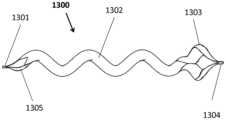
도 35b는 도 34의 조립체(1200)에 포함된 나선형 구성요소(1300)를 도시한다. 명료성을 위하여, 본 이미지에서 구성요소(1300)의 몸체 섹션(1302)을 따르는 스트러트의 상세 사항은 도시되어 있지 않다. 장치 조립을 위해 사용되는 근위 칼라(1301) 및 근위 스트러트들(1305)이 도시되어 있다. 조각 보호 섹션(1303) 및 방사선 불투과성 원위 마커(1304)가 또한 도시되어 있다. 이러한 구성에서, 몸체 섹션(1302)은 그의 길이를 따라서 일정한 직경을 갖지만, 다른 구성(미도시)에서 직경은 길이를 따라서 증가하거나 감소할 수 있다. 유사하게, 다른 구성에서, 나선 직경 및 피치가 길이를 따라서 가변될 수 있거나, 또는 구성요소가 직선형 섹션과 나선형 섹션의 조합을 가질 수 있다. 이러한 구성요소의 핀치 능력에 더하여, 이는 또한 하기와 같은 내부 채널 기능을 제공한다: 전개 시 혈류의 즉각적인 복원, 혈전을 가로지른 압력 구배를 약화시킴, 콘트라스트(contrast) 유동 및 원위 시각화를 용이하게 함, 및 원위 색전에 대한 흡인 채널로서 작용함. 장치(1300)의 스트러트 및 크라운 패턴은 중간 및 원위 부분들이 내부 채널 기능을 제공하기 위하여 더 조밀하게 스캐폴딩되면서 근위 부분이 핀치 능력을 제공하도록 몸체 섹션(1302)의 길이를 따라서 가변될 수 있다.FIG. 35B shows
본 발명의 다른 실시예가 도 36에 도시되어 있다. 이러한 장치(1400)는 또한 내부 나선형 관형 구성요소(1403)와 외부 케이지(1401)의 조립체이다. 이러한 구성에서, 조각 보호 특징부(1406)는 외부 케이지(1401)에 일체형이다. 외부 케이지(1401) 및 나선형 구성요소(1403)는 근위 조인트(1405)에서 근위 샤프트(1404)에 연결된다. 방사선 불투과성 원위 팁(1402)이 이러한 조립체에서는 외부 케이지(1401)에 결합된다.Another embodiment of the present invention is shown in Figure 36. This
도 37은 도 7a에 도시된 장치의 다른 실시예를 도시한다. 이러한 장치(1450)에서, 근위 섹션(1451)은 마이크로카테터에 의해 부분적으로 재피복되는 경우에 혈전을 핀치하도록 구성된다. 앞서와 같이, 근위 스트러트들(1456)은 큰 개방 각들을 갖고, 셀 크기는 혈전 돌출을 촉진하여 재피복 동안 마이크로카테터와 장치(1450)사이의 핀칭을 용이하게 한다. 중간 섹션(1452)은 근위 섹션보다 큰 직경으로 확장되도록 구성되어 혈관 만곡부 및 분지부를 지나는 혈전의 후퇴 동안 혈전의 파지 및 보유를 제공한다. 근위 섹션(1451) 및 중간 섹션(1452)은 상이한 스트러트 길이들 및 절단 패턴들 및 그에 따른 상이한 반경방향 힘 특성을 갖는다. 일 실시예에서, 근위 섹션(1454)의 반경방향 힘이 일정한 전개 직경(예컨대 1.0 mm)에 대해 중간 섹션(1455)의 대응하는 반경방향 힘보다 큰 한편, 다른 실시예에서, 중간 섹션(1452)의 반경방향 힘은 동일한 전개 직경에 대해 근위 섹션(1451)의 반경방향 힘보다 크다.Figure 37 shows another embodiment of the device shown in Figure 7A. In this
도 38은 본 발명에서 상세히 설명된 임의의 장치의 핀치 부분의 전형적인 스트러트 절단 패턴을 도시한다. 스트러트들(1501)은, 이동 방향에 대한 스트러트의 각이 크면 클수록 혈전을 지나서 활주하기보다는 오히려 혈전을 파지하는 스트러트의 능력이 더 커지기 때문에, 개선된 혈전 파지를 촉진시키는 종방향 혈관 축에 대한 큰 개방 각을 갖는다. 유사하게, 혈전 내의 이동 방향에 거의 수직인 크라운의 길이를 최대화함으로써 크라운(1502)의 내경은 증가되어 혈전 파지를 또한 개선한다. 스트러트 커넥터(1503)의 길이는 전체 셀 영역(1504)을 증가시켜 작은 반경방향 힘 및 작은 스트러트 표면적을 갖는 장치에 셀들의 링들을 제공하여 이들 셀 내로의 혈전의 매설 및 돌출을 촉진한다. 장치가 마이크로카테터에 의해 재피복되는 경우, 돌출된 혈전은 스트러트들(1501)에 대항하여 그리고 크라운 공간(1505) 내로 밀려서 제자리에서 혈전을 포획하고 혈전을 핀칭한다.Figure 38 shows a typical strut cutting pattern of a pinch portion of any device detailed herein.
장치 절단 패턴의 다른 실시예가 도 39에 도시되어 있다. 이러한 구성에서, 크라운(1551)에 인접한 스트러트 형상 및 만곡부 각(1553)은, 마이크로카테터(1555)에 의한 재피복 시, 서로 접한 스트러트들이 서로 만나서(1554) 셀 영역(미도시) 내로 돌출되어 있는 혈전을 파지하는 것을 돕도록 다른 핀치 지점을 생성하도록 크기설정된다.Another embodiment of a device cut pattern is shown in FIG. 39. In this configuration, the strut shape and
도 38에서 설명되는 바와 같이, 절단 패턴 내의 크라운 내경이 크면 클수록 혈관의 종축(및 혈전 이동 방향)에 거의 수직인 크라운의 일부가 길면 길수록, 혈전 분리 능력은 더 좋아진다. 도 40은 마이크로카테터를 통하여 표적 혈관 위치로 전달하기 위한 로딩된 구성으로 장치가 감싸일 수 있게 하는 동안 크라운 직경이 최대화되는 것을 허용하는 크라운 구성을 도시한다. 감싸인 직경을 최소화하기 위하여, 크라운들(1603, 1604, 1605)은, 접혀진 구성에서, 크라운들이 짧은 커넥터, 예를 들어 1606의 어느 측의 공간 내로 끼워맞춤되도록 종축을 따라서 오프셋된다. 이러한 크라운 오프셋을 발생시키기 위하여, 서로 접한 스트러트들(1601, 1602)은 상이한 길이들을 갖는다.As illustrated in Figure 38, the larger the crown inner diameter in the cutting pattern and the longer the portion of the crown that is approximately perpendicular to the longitudinal axis of the blood vessel (and the direction of clot movement), the better the clot separation ability. Figure 40 shows a crown configuration that allows the crown diameter to be maximized while allowing the device to be wrapped in a loaded configuration for delivery to a target vessel location via a microcatheter. To minimize the wrapped diameter, the
도 41은 크라운(1653)이 마이크로카테터(1651)에 의한 재피복 동안 그의 완전한 직경을 유지하여 최대량의 혈전이 마이크로카테터 팁(1654)에 의해 셀(1655)로부터 크라운 공간(1652) 내로 밀려서 핀치를 생성할 수 있게 하도록 절단 패턴이 구성되는 장치의 다른 실시예를 도시한다. 도 42는 크라운 공간(1701)이 개선된 혈전 핀칭을 위하여 최대화되는 도 41에서 설명된 것들과 근위 대면 크라운들(1703)이 유사한 절단 패턴의 실시예를 도시한다. 이러한 구성에서, 원위 대면 크라운 직경(1704)은 크라운이 혈전 핀칭을 위하여 필요하지 않기 때문에 감소되고, 감소된 직경은 인접한 스트러트들(1702)에서 작은 재피복 힘 및 증가된 반경방향 힘을 가능하게 할 수 있다.41 shows that the
도 43은 도 42에서 상세히 설명된 바와 같이 개선된 혈전 핀칭을 위하여 근위 대면 크라운들(1721, 1723)이 원위 대면 크라운들(1725)보다 큰 직경을 갖는 장치의 실시예를 도시한다. 이러한 장치의 종축을 따르는 교호하는 셀들의 링들은 상이한 면적들을 갖는데, 셀(1726)은 1720보다 큰 면적을 갖는다. 따라서, 더 많은 혈전이 셀(1726) 내로 매설 및 돌출되기 쉽다. 셀(1726) 내로 돌출되는 혈전은 재피복 시 마이크로카테터에 의해 크라운(1723)을 향하여 밀릴 것이다. 의사에 대한 우수한 촉각 피드백과 함께 이러한 재피복이 부드러운 것을 보장하기 위하여, 스트러트(1724)의 길이는, 카테터가 작은 반경방향 힘 세그먼트들로부터 큰 반경방향 힘 세그먼트들로 감에 따라 '범핑(bumping)' 느낌을 감소시키도록 증가된다. 더욱이, 스트러트(1722)의 길이는 크라운(1723)을 지지하고 있는 스트러트들의 링 내의 반경방향 힘을 증가시키도록 짧아진다. 이는 마이크로카테터에 의한 재피복 중에 오랫동안 크라운(1723)을 확장된 채로 유지하여 핀치 유효성을 증가시킨다.Figure 43 shows an embodiment of the device where the proximal facing crowns 1721, 1723 have a larger diameter than the distal facing crowns 1725 for improved thrombus pinching as detailed in Figure 42. Alternating rings of cells along the longitudinal axis of this device have different areas, with
도 44a 내지 도 44c는 스트러트의 길이를 따라 혈전 핀칭을 촉진시키는 스트러트/크라운 구성을 도시한다. 도 44a는 자유롭게 확장된 구성 상태에 있는 스트러트들(1757, 1758)을 도시한다. 스트러트(1758)는 그가 크라운(1753)에 접근하는 일련의 만곡부들(1751, 1752, 1759)을 포함하도록 생성된다. 유사하게, 스트러트(1757)는 일련의 정합 만곡부들(1754, 1755, 1756)을 포함한다. 장치가 마이크로카테터 내에 재피복됨에 따라, 장치의 직경은 감소되고 스트러트들은 서로 더 가깝게 이동한다. 도 44b는 직경이 감소됨에 따라, 스트러트들 내의 만곡부들이 상호잠금되어 지점들(1808, 1805) 사이 및 지점들(1804, 1807) 사이와 같은 핀치 지점들을 생성하는 것을 도시한다. 이는 도 44c에 도시된 바와 같이 2개의 스트러트들 사이에 매설된 돌출된 혈전을 파지하는 것을 돕는다. 도 44c에서, 혈전(1852)의 일부가 스트러트들 사이의 셀 내로 돌출된다. 장치가 마이크로카테터(미도시)에 의해 재피복됨에 따라, 스트러트들(1850, 1851)은 서로 더 가까이 이동하여 돌출된 혈전(1853)에 대한 핀치를 발생시킨다. 이러한 혈전 핀칭은 향상된 혈전 분리 능력 및 접근 카테터 내로의 안전한 혈전 회수와 함께 장치 효과를 개선한다.Figures 44A-44C illustrate a strut/crown configuration that promotes thrombus pinching along the length of the strut. Figure 44A shows
본 발명의 다른 실시예가 도 45에 도시되어 있다. 본 도면은 장치(1900)의 프로파일 및 외부 형상을 도시하지만 명료성을 위하여 스트러트 패턴을 도시하지는 않았다. 본 실시예에서, 장치의 근위 섹션(1905)은 도 29 내지 도 33에서 설명된 바와 같이 나사형 구성으로 형성된다. 이러한 근위 섹션(1905)은 또한 마이크로카테터에 의해 부분적으로 재피복되는 경우에 혈전을 핀치하도록 구성된다. 앞서와 같이, 스트러트들은 혈전 핀칭을 용이하게 하는 개방 각 및 크라운들을 갖고 셀 크기는 재피복 중에 마이크로카테터와 장치 사이의 핀칭을 추가로 개선하기 위하여 혈전 돌출을 촉진한다. 몸체 섹션(1901)은 실린더형 또는 균일한 형상으로 확장되도록 구성되어 혈관 만곡부 및 분지부를 지나는 혈전의 후퇴 동안 혈전의 파지 및 보유를 제공한다. 몸체 섹션은 또한 적혈구 함량이 30 내지 100% 범위인 더 부드러운 혈전, 그러나 특히 적혈구 함량이 50% 초과인 혈전의 파지 및 보유에 특히 적합하다. 이러한 구성에서, 장치는, 몸체 섹션(1901)에 의해 더 부드러운 또는 이종 혈전을 파지 및 보유하면서, 근위 섹션(1905)에 걸쳐 마이크로카테터에 의한 부분적인 재피복에 의해 피브린 풍부 혈전을 파지함으로써 피브린 풍부 혈전 및 적혈구 풍부 혈전을 분리 및 보유하는 데 효과적이다. 본 도면에 도시된 장치(1900)는 근위 조인트(1904)에서 근위 샤프트(미도시)에 연결되고 조각 보호 구역(1902)을 갖는다. 근위 나사형 섹션(1905)은 1906에서 몸체 섹션(1901)에 연결된다. 이러한 연결은 중심에 위치되어 몸체 섹션과 동심을 이룰 수 있거나 또는 편심될 수 있어서, 예를 들어 몸체 섹션의 외부 표면과 정렬한다. 근위 관형 섹션과 몸체 섹션 사이의 확개된 섹션(1903)은 개선된 보유 및 조각 보호를 위하여 몸체 섹션 내로의 혈전 이동을 용이하게 하도록 큰 셀 개구들을 포함할 수 있다.Another embodiment of the present invention is shown in Figure 45. This figure shows the profile and external shape of
도 46은 도시된 바와 같이 방향 'A'로부터 보았을 때 도 45에 도시된 장치(1900)의 단부도를 도시한다. 본 도면에서, 나사형 외부 표면(1951)은 몸체 섹션 직경(1952)(
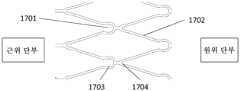
도 47에 도시된 실시예(2000)는 추가의 스트러트 및 구조의 상세 사항을 갖는, 도 45 및 도 46에 도시된 장치와 유사한 형상을 갖는다. 본 실시예는 근위 스트러트들(2008)에 의해 근위 샤프트(2007)에 연결된 상태가 도시되어 있다. 근위 섹션(2001)은 나사형 구성으로 형성되고 몸체 섹션(2002)은 실린더형 형상으로 형성된다. 장치의 원위 단부는 조각 보호 능력을 제공하기 위하여 원추 형상을 형성한다. 방사선 불투과성 코일 또는 마커(2003)가 투시검사 하에서의 가시성을 위하여 원위 팁에 추가된다. 추가의 방사선 불투과성 마커(2005)가 나사형 섹션으로부터 몸체 섹션으로의 전이부에서 또는 그 근처에서 장치에 추가된다. 이러한 마커(2005)는 나사형 섹션(2001)의 단부를 하이라이트하고 마이크로카테터에 의한 재피복을 멈추도록 최적 지점을 구별하는 데 사용될 수 있다. 이러한 방사선 불투과성 마커는 또한 적혈구 풍부 혈전에 대하여 장치를 혈전의 근위 면과 정렬하는 데 사용될 수 있다. 유사하게, 샤프트(2007)의 원위 단부 상의 방사선 불투과성 코일(미도시)은 나사형 핀치 섹션(2001)을 피브린 풍부 혈전의 근위 면과 정렬하는 데 사용될 수 있다. 근위 나사형 섹션은 전형적으로 길이가 5 내지 30 mm이고 바람직한 실시예에서는 길이가 8 내지 15mm이다. 마이크로카테터에 의한 재피복 과정 동안 증가된 시각적 피드백 및 명료성을 제공하기 위하여 나사형 섹션을 따라서 추가의 방사선 불투과성 마커들이 추가될 수 있다. 도 47은 또한 혈전이 몸체 섹션(2002) 내측에 부분적으로 또는 완전히 들어가는 것을 용이하게 하도록 설계된, 나사형 튜브로부터 몸체 섹션으로의 직경 전이부에 있는 셀 개구들(2006)을 도시한다.
도 48은 단지 샤프트(2052) 및 나사형 및 몸체 섹션들(2051)의 외부 형상이 도시된 장치의 다른 실시예(2050)를 도시한다. 본 실시예에서, 나사형 섹션(2056)의 단부를 구별하는 방사선 불투과성 마커(2055)는 근위 샤프트(2052)에서 연장부(2054) 상에 장착된다. 이러한 샤프트 연장부(2054)는 나사형 섹션을 샤프트(2052)에 연결하는 근위 조인트(2053)의 원위로 이어진다.FIG. 48 shows another
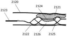
도 49a는 도 6a 내지 도 6d에서 앞서 상세히 설명된 실시예(2100)의 부분 평면도를 도시하고 큰 셀 영역(2102)을 도시하는데, 장치가 마이크로카테터에 의해 재피복되는 경우에 상기 큰 셀 영역은 장치 내로의 혈전 돌출을 촉진하여 그가 스트러트들(2103, 2104)에 고정될 수 있게 한다. 도 49b에서, 장치(2122)는 동맥 혈관(2120) 내에 위치된 혈전(2121) 내에서 전개된 채로 도시되어 있다. 장치(2122)는 근위 샤프트(2123)에 연결된다. 장치의 전개 시, 스트러트들 및 셀들의 링(2125)이 혈전 내에 매설되는 한편, 큰 개방 셀 섹션(2126) 위에 위치된 혈전 섹션(2124)은 장치 내로 돌출된다. 큰 개방 셀 섹션은 장치 내로의 혈전 돌출을 촉진하여, 혈전 압축 및 이후의 혈관 벽(2120)과의 마찰의 증가를 최소화한다.FIG. 49A shows a partial plan view of the
도 49c는 혈전(2141)의 돌출 섹션(2142)이 어떻게 카테터 팁(2145)에 의해 스트러트들 및 크라운들의 링(2144)에 대항하여 밀려서 혈전에 대한 파지를 발생시켜 혈관계로부터의 분리 및 회수를 용이하게 하는지를 도시한다.FIG. 49C illustrates how the protruding
여기에 개시된 본 발명은 카테터에 의해 재피복되는 경우에 기존의 스텐트 회수기 기법보다 혈전 파지 및 핀치의 발생 시 더 효과적이고 신뢰성을 갖는다. 도 50a 내지 도 50c는 기존의 스텐트 회수기 장치(2200)(종래 기술)가 마이크로카테터에 의해 재피복되는 경우에 어떤 일이 일어나는지를 도시한다. 도 50a는 혈전(2201) 내에서 전개된 스텐트 회수기(2203)를 도시한다. 스트러트 매설이 혈전(2201) 내에서 일어나고, 일부 혈전은 개방 셀들(2203) 내로 돌출된다. 전형적인 스텐트 회수기는 외경이 4 내지 6mm 범위에 있고, 장치(2224)가 도 50b에 도시된 바와 같이 재피복됨에 따라, 이는 수축되고 혈전(2220)으로부터 벗어난다. 그러므로, 마이크로카테터(2221)가 전진됨에 따라, 혈전(2220) 내에 매설되었던 스트러트들(2223)은 혈전 표면으로부터 벗어나고, 셀 내의 혈전 돌출부를 놓쳐서 마이크로카테터가 완전히 전진하는 것을 허용하여, 혈전 아래에서 장치를 재피복한다. 도 50c는, 장치가 카테터(2240)에 의해 재피복됨에 따라, 스트러트 길이(2242) 및 크라운 개방 각(2244)이 어떻게 장치의 재피복 각(2241)에 영향을 주는지를 도시한다. 수직으로부터의 이러한 각(2241)이 크면 클수록, 장치 스트러트들이 재피복 중에 혈전의 표면으로부터 벗어날 가능성이 더 커진다. 길이(2245)는 카테터가 전진됨에 따라 장치 직경이 수축하기 시작하는 카테터 팁으로부터의 거리이다. 이러한 길이는 재피복 각이 (수직으로부터) 증가함에 따라 증가하여, 장치 스트러트들의 혈전과의 접촉을 감소시킨다.The invention disclosed herein is more effective and reliable in the event of thrombus grab and pinch than existing stent retriever techniques when re-catheterized. Figures 50A-50C illustrate what happens when an existing stent retriever device 2200 (prior art) is re-catheterized with a microcatheter. 50A shows a
도 50a 내지 도 50c의 기존의 스텐트 회수기 기법과 비교 시, 도 51a 내지 도 50c는 혈전 내에서 전개된 본 발명의 실시예를 도시한다. 도 51a는 혈전(2301) 내에서 전개된, 본 특허 내의 다른 곳에서 설명된 것과 유사한 장치(2300)를 도시한다. 스트러트들(2303)의 링들은 혈전 내에 매설되고 혈전(2302)은 큰 개방 셀들(2305) 내로 돌출된다. 장치가 도 51b에 도시된 바와 같이 카테터에 의해 재피복됨에 따라, 스트러트 길이, 크라운 구성, 및 장치 길이를 따른 반경방향 힘 프로파일은 카테터 팁이 접근함에 따라 혈전 내의 스트러트 매설 및 셀들 내에서의 혈전 돌출을 유지한다. 그러므로, 혈전(2322)은 재피복 과정 동안 장치 셀 내에서 여전히 돌출되어 있고 인접한 스트러트(2326) 및 크라운(2325)에 대항하여 밀려서, 그를 제위치에서 핀칭한다. 크라운(2325)은 또한 스트러트들(2324)의 링에 의해 지지되어 그가 재피복 과정 중에 더 오랫동안 혈전 내에서 확장되고 그 내에 매설된 채로 유지하는 것을 보장한다. 이러한 성능 특성은 장치 직경이 카테터 팁의 바로 부근에서를 제외하고는 수축하지 않는 것을 보여주는 도 51c에 도시된 (수직으로부터의) 감소된 재피복 각 및 유의하게 감소된 길이(2345)에 반영된다. 이러한 특징부는 또한 도 3a 내지 도 3d에서 이전에 설명된 바와 같이 장치 길이를 따르는 교호하는 더 크고 더 작은 반경방향 힘 프로파일에 의해 가능하게 된다.Figures 51A-50C show an embodiment of the invention deployed within a thrombus, when compared to the existing stent retrieval technique of Figures 50A-50C. Figure 51A shows a
이러한 장치의 바람직한 실시예는 외경이 2 내지 3 mm이고, 이는 전형적으로 4 내지 6 mm로 확장되는 표준 스텐트 회수기보다 재피복 과정 중에 더 큰 크라운 확장 각을 허용하는 더 짧은 스트러트 길이를 가능하게 한다. 이는 도 52a 및 도 52b에 도시되어 있는데, 여기서 도 52a는 2D 구성으로 펼쳐진, 4mm 외경을 갖는 3셀 종래 스텐트 회수기의 확장된 스트러트들(2402)을 도시한다. 이러한 동일한 장치는 2mm 직경으로 수축된 경우에 도 52b에 도시되어 있는데, 이는 스트러트 길이(2423)를 도시하고 크라운 개방 각이 어떻게 도 52a의 2401로부터 도 52b의 2422로 감소되었는지를 도시한다. 비교에서, 본 발명의 스트러트 구성이 핀칭을 용이하게 하기 위한 스트러트들의 큰 확장된 각(2442)과 큰 크라운 ID(2443)를 도시하는 도 53에 도시되어 있다. 이러한 장치는 2mm 직경에서 여전히 유효한데, 이는 스트러트 매설 및 혈전 결합을 유지하기 위하여 장치에 의해 혈전을 혈관 벽에 대해 부분적으로 또는 완전히 고정시키기보다는 오히려 혈전 결합 및 보유가 마이크로카테터 팁과 장치의 크라운 및 스트러트들 사이의 혈전을 핀치함으로써 제공되기 때문이다.A preferred embodiment of this device has an outer diameter of 2 to 3 mm, which allows for a shorter strut length allowing for a larger crown expansion angle during the recovering process than standard stent retrievers, which typically expand to 4 to 6 mm. This is illustrated in FIGS. 52A and 52B, where FIG. 52A shows the expanded struts 2402 of a 3-cell conventional stent retriever with a 4 mm outer diameter, unfolded in a 2D configuration. This same device is shown in Figure 52B when shrunk to a 2 mm diameter, showing the strut length 2423 and how the crown opening angle has been reduced from 2401 in Figure 52A to 2422 in Figure 52B. In comparison, the strut configuration of the present invention is shown in Figure 53, which shows a large crown ID 2443 and a large expanded angle 2442 of the struts to facilitate pinching. These devices are still effective at 2 mm diameter, as thrombus engagement and retention is achieved by the microcatheter tip and crown of the device, rather than by partially or fully anchoring the thrombus against the vessel wall by the device to maintain strut embedment and thrombus engagement. This is because it is provided by pinching the clot between the struts.
도 54a 및 도 54b에 도시된 스트러트 구성은 핀치를 발생시키고 폐색 혈전을 분리하는 것을 돕는 추가 이득을 제공한다. 도 54a의 장치(2504)의 스트러트 패턴은 2D 구성으로 펼쳐진 상태로 도시되어 있다. 장치(2504)가 마이크로카테터에 의해 재피복되는 경우, 외경은 감소되어 네크 지점(2505)이 반대편인 네크 지점(2501)을 향하여 이동하게 한다. 이는 마이크로카테터가 전진하여 크라운(2502)에 대항하여 혈전을 미는 것에 따라 셀(2503) 내에 돌출된 혈전을 파지하고 혈전을 이 위치에 유지시키는 것을 도울 수 있어서, 이를 고정하고 핀치 파지를 발생시킨다. 도 54b는 또한, 네크 지점들(2553)들이 어떻게 서로 만나서 마이크로카테터 팁(2555)과 크라운(2551) 사이에 위치된 혈전(미도시)에 대한 추가 파지를 제공하여, 그가 만곡부 및 분지부를 지나서 접근 카테터로 후퇴됨에 따라 핀칭을 용이하게 하고 또한 혈전의 파지 및 보유를 향상시키는지를 도시한다.The strut configuration shown in FIGS. 54A and 54B provides the additional benefit of generating a pinch and helping to dislodge the occlusive thrombus. The strut pattern of
본 발명의 특정 실시예가 도시되고 설명되었지만, 다양한 변형이 본 발명의 사상 및 범주로부터 벗어남이 없이 이루어질 수 있음이 상기 설명으로부터 명백할 것이다. 예를 들어, 본 명세서에 기술된 실시예가 특정 특징부를 언급하지만, 본 발명은 특징부의 상이한 조합을 갖는 실시예를 포함한다. 본 발명은 또한 기술된 특정 특징부들 모두를 포함하지는 않는 실시예를 포함한다.Although specific embodiments of the invention have been shown and described, it will be apparent from the foregoing description that various changes may be made without departing from the spirit and scope of the invention. For example, although the embodiments described herein refer to specific features, the invention includes embodiments with different combinations of features. The invention also includes embodiments that do not include all of the specific features described.
본 발명은 구성과 상세 사항이 달라질 수 있는 전술된 실시예로 제한되지 않는다.The present invention is not limited to the above-described embodiments, which may vary in configuration and details.
Claims (48)
Translated fromKorean확장가능 구조물 및 세장형 부재를 포함하고,
상기 세장형 부재는 근위 단부 및 원위 단부를 갖고, 상기 세장형 부재는 그 원위 단부에서 상기 확장가능 구조물에 연결되고,
상기 확장가능 구조물은 상기 확장가능 구조물이 확장시 완전히 구속되는 구속된 전달 구성, 확장된 혈전 결합 전개된 구성, 및 상기 확장가능 구조물이 확장시 적어도 부분적으로 구속되는 적어도 부분적으로 구속된 혈전 핀칭(pinching) 구성을 갖고,
상기 확장가능 구조물의 적어도 일부는 상기 확장된 혈전 결합 전개된 구성에서 혈전과 결합하도록 그리고 상기 확장된 혈전 결합 전개된 구성으로부터 상기 혈전 핀칭 구성으로의 이동 시 혈전을 핀치하도록 구성되고,
상기 확장가능 구조물은 상기 확장된 혈전 결합 전개된 구성으로부터 상기 혈전 핀칭 구성으로의 이동 시 혈전을 핀치하도록 구성된 혈전 핀칭 구조물을 포함하고,
상기 확장가능 구조물은 본체 부분을 포함하고, 상기 혈전 핀칭 구조물의 직경은 상기 본체 부분의 직경보다 작고,
상기 혈전 핀칭 구조물은 복수의 혈전 수용 셀들을 포함하고, 하나의 셀은 크라운(crown)들 사이에서 연장된 스트러트들을 포함하고, 상기 스트러트들은 상기 혈전 제거 장치가 상기 확장된 혈전 결합 전개된 구성으로부터 상기 적어도 부분적으로 구속된 혈전 핀칭 구성으로 이동됨에 따라 상기 셀 내에 위치된 혈전을 핀치하도록 구성되고,
인접한 스트러트들은 상기 스트러트들을 결합하는 상기 크라운을 향하여 원위방향으로 좁아지는 채널을 한정하고,
인접한 스트러트들 또는 파상부(undulation)들은 적어도 하나의 만곡부를 포함하고, 상기 만곡부들은 상기 혈전 제거 장치가 상기 혈전 핀칭 구성으로 이동됨에 따라 상기 인접한 스트러트들의 만곡부들이 상호결합하도록 구성된, 혈전 제거 장치.A thrombectomy device for removing blood clots from blood vessels in the body, comprising:
comprising expandable structures and elongated members,
the elongated member has a proximal end and a distal end, and the elongated member is connected to the expandable structure at its distal end,
The expandable structure may include a constrained delivery configuration in which the expandable structure is fully constrained when expanded, an expanded thrombus binding deployed configuration, and an at least partially constrained thrombus pinching configuration in which the expandable structure is at least partially constrained when expanded. ) has the composition,
At least a portion of the expandable structure is configured to engage a thrombus in the expanded thrombus engagement deployed configuration and to pinch a thrombus upon movement from the expanded thrombus engagement deployed configuration to the thrombus pinching configuration,
the expandable structure comprises a thrombus pinching structure configured to pinch a thrombus upon movement from the expanded thrombus binding deployed configuration to the thrombus pinching configuration,
wherein the expandable structure includes a body portion, and the diameter of the thrombus pinching structure is smaller than the diameter of the body portion,
The clot pinching structure includes a plurality of clot receiving cells, one cell including struts extending between crowns, the struts allowing the clot removal device to extract the clot from the extended clot-engaging deployed configuration. configured to pinch a thrombus located within said cell as it moves into the at least partially restrained thrombus pinching configuration;
Adjacent struts define a channel that narrows distally toward the crown joining the struts,
Wherein the adjacent struts or undulations include at least one bend, the undulations being configured to cause the undulations of the adjacent struts to interengage as the clot removal device is moved into the clot pinching configuration.
상기 스트러트들의 망은 확장된 상태에서 혈전과 결합하도록 구성되고, 상기 망은 상기 확장된 상태에서 상기 망의 적어도 일부가 혈전에 상호침투(interpenetrate)하도록 구성되고,
상기 망은 추가로, 상기 혈전과의 상호침투의 상태에 있는 동안 상기 망이 접혀진 경우에 상기 망의 적어도 일부가 상기 혈전의 적어도 일부를 핀치하도록 구성된, 혈전 제거 장치.6. The system of any one of claims 1, 4, and 5, wherein the expandable structure is tubular and comprises a network of interconnected struts,
wherein the network of struts is configured to engage a thrombus in the expanded state, the network being configured such that at least a portion of the network interpenetrates the thrombus in the expanded state,
wherein the mesh is further configured such that when the mesh is folded while in a state of interpenetration with the blood clot, at least a portion of the mesh pinches at least a portion of the blood clot.
Applications Claiming Priority (7)
| Application Number | Priority Date | Filing Date | Title |
|---|---|---|---|
| US201562259976P | 2015-11-25 | 2015-11-25 | |
| US14/952,202US10363054B2 (en) | 2014-11-26 | 2015-11-25 | Clot retrieval device for removing occlusive clot from a blood vessel |
| US62/259,976 | 2015-11-25 | ||
| US14/952,202 | 2015-11-25 | ||
| US201662342012P | 2016-05-26 | 2016-05-26 | |
| US62/342,012 | 2016-05-26 | ||
| PCT/EP2016/078595WO2017089424A1 (en) | 2015-11-25 | 2016-11-23 | A clot retrieval device for removing occlusive clot from a blood vessel |
Publications (2)
| Publication Number | Publication Date |
|---|---|
| KR20180087320A KR20180087320A (en) | 2018-08-01 |
| KR102648959B1true KR102648959B1 (en) | 2024-03-20 |
Family
ID=58762985
Family Applications (1)
| Application Number | Title | Priority Date | Filing Date |
|---|---|---|---|
| KR1020187017658AActiveKR102648959B1 (en) | 2015-11-25 | 2016-11-23 | A blood clot retrieval device for removing occluding blood clots from blood vessels. |
Country Status (12)
| Country | Link |
|---|---|
| EP (2) | EP3380021B1 (en) |
| JP (1) | JP6961590B2 (en) |
| KR (1) | KR102648959B1 (en) |
| CN (1) | CN108601599B (en) |
| AU (1) | AU2016358836A1 (en) |
| BR (1) | BR112018010607A2 (en) |
| CA (1) | CA3006614A1 (en) |
| CO (1) | CO2018006459A2 (en) |
| IL (1) | IL259552A (en) |
| MX (1) | MX2018006446A (en) |
| RU (1) | RU2018122453A (en) |
| WO (1) | WO2017089424A1 (en) |
Families Citing this family (38)
| Publication number | Priority date | Publication date | Assignee | Title |
|---|---|---|---|---|
| US9402707B2 (en) | 2008-07-22 | 2016-08-02 | Neuravi Limited | Clot capture systems and associated methods |
| ES2683943T3 (en) | 2010-10-22 | 2018-09-28 | Neuravi Limited | Clot capture and removal system |
| US11259824B2 (en) | 2011-03-09 | 2022-03-01 | Neuravi Limited | Clot retrieval device for removing occlusive clot from a blood vessel |
| EP4566553A3 (en) | 2011-03-09 | 2025-08-06 | Neuravi Limited | A clot retrieval device for removing occlusive clot from a blood vessel |
| US12076037B2 (en) | 2011-03-09 | 2024-09-03 | Neuravi Limited | Systems and methods to restore perfusion to a vessel |
| ES2708786T3 (en) | 2013-03-14 | 2019-04-11 | Neuravi Ltd | Clot recovery device to remove occlusive clots from a blood vessel |
| WO2014140092A2 (en) | 2013-03-14 | 2014-09-18 | Neuravi Limited | Devices and methods for removal of acute blockages from blood vessels |
| US9433429B2 (en) | 2013-03-14 | 2016-09-06 | Neuravi Limited | Clot retrieval devices |
| EP3682821B1 (en) | 2014-11-26 | 2022-05-11 | Neuravi Limited | A clot retrieval device for removing an occlusive clot from a blood vessel |
| US10617435B2 (en) | 2014-11-26 | 2020-04-14 | Neuravi Limited | Clot retrieval device for removing clot from a blood vessel |
| US11253278B2 (en)* | 2014-11-26 | 2022-02-22 | Neuravi Limited | Clot retrieval system for removing occlusive clot from a blood vessel |
| WO2018033401A1 (en) | 2016-08-17 | 2018-02-22 | Neuravi Limited | A clot retrieval system for removing occlusive clot from a blood vessel |
| EP3500191B1 (en) | 2016-08-17 | 2020-09-23 | Neuravi Limited | A clot retrieval system for removing occlusive clot from a blood vessel |
| EP3509509B1 (en) | 2016-09-06 | 2021-03-31 | Neuravi Limited | A clot retrieval device for removing occlusive clot from a blood vessel |
| AU2018204059A1 (en)* | 2017-06-28 | 2019-01-17 | Neuravi Limited | Clot retrieval system for removing occlusive clot from a blood vessel |
| CN115120302B (en)* | 2018-01-30 | 2025-03-18 | 上海沃比医疗科技有限公司 | Thrombus capturing device and method |
| US10842498B2 (en) | 2018-09-13 | 2020-11-24 | Neuravi Limited | Systems and methods of restoring perfusion to a vessel |
| US11406416B2 (en) | 2018-10-02 | 2022-08-09 | Neuravi Limited | Joint assembly for vasculature obstruction capture device |
| US12285182B2 (en) | 2018-10-10 | 2025-04-29 | Innova Vascular, Inc. | Devices and methods for removing an embolus |
| US11109939B2 (en)* | 2019-06-14 | 2021-09-07 | DePuy Synthes Products, Inc. | Intravascular devices with radiopaque body markers |
| US11266427B2 (en) | 2019-07-10 | 2022-03-08 | Neuravi Limited | Self-expanding intravascular medical device |
| KR102232949B1 (en)* | 2019-07-29 | 2021-03-26 | 주식회사 엔벤트릭 | Device for removing clot |
| US11376034B2 (en)* | 2019-09-19 | 2022-07-05 | Stryker Corporation | Devices for removing obstructing materials from blood vessels |
| US11712231B2 (en) | 2019-10-29 | 2023-08-01 | Neuravi Limited | Proximal locking assembly design for dual stent mechanical thrombectomy device |
| US11517340B2 (en)* | 2019-12-03 | 2022-12-06 | Neuravi Limited | Stentriever devices for removing an occlusive clot from a vessel and methods thereof |
| US11717308B2 (en) | 2020-04-17 | 2023-08-08 | Neuravi Limited | Clot retrieval device for removing heterogeneous clots from a blood vessel |
| US11730501B2 (en) | 2020-04-17 | 2023-08-22 | Neuravi Limited | Floating clot retrieval device for removing clots from a blood vessel |
| US11871946B2 (en) | 2020-04-17 | 2024-01-16 | Neuravi Limited | Clot retrieval device for removing clot from a blood vessel |
| US11737771B2 (en) | 2020-06-18 | 2023-08-29 | Neuravi Limited | Dual channel thrombectomy device |
| US11937836B2 (en)* | 2020-06-22 | 2024-03-26 | Neuravi Limited | Clot retrieval system with expandable clot engaging framework |
| US11395669B2 (en)* | 2020-06-23 | 2022-07-26 | Neuravi Limited | Clot retrieval device with flexible collapsible frame |
| US11439418B2 (en) | 2020-06-23 | 2022-09-13 | Neuravi Limited | Clot retrieval device for removing clot from a blood vessel |
| US11864781B2 (en) | 2020-09-23 | 2024-01-09 | Neuravi Limited | Rotating frame thrombectomy device |
| CN112089477B (en)* | 2020-10-16 | 2025-01-14 | 上海腾复医疗科技有限公司 | Basket-type thrombectomy device |
| US11937837B2 (en) | 2020-12-29 | 2024-03-26 | Neuravi Limited | Fibrin rich / soft clot mechanical thrombectomy device |
| US12029442B2 (en) | 2021-01-14 | 2024-07-09 | Neuravi Limited | Systems and methods for a dual elongated member clot retrieval apparatus |
| US12064130B2 (en) | 2021-03-18 | 2024-08-20 | Neuravi Limited | Vascular obstruction retrieval device having sliding cages pinch mechanism |
| US11974764B2 (en) | 2021-06-04 | 2024-05-07 | Neuravi Limited | Self-orienting rotating stentriever pinching cells |
Citations (1)
| Publication number | Priority date | Publication date | Assignee | Title |
|---|---|---|---|---|
| US20140200608A1 (en)* | 2011-03-09 | 2014-07-17 | Neuravi Limited | Clot retrieval device for removing occlusive clot from a blood vessel |
Family Cites Families (51)
| Publication number | Priority date | Publication date | Assignee | Title |
|---|---|---|---|---|
| US5895398A (en)* | 1996-02-02 | 1999-04-20 | The Regents Of The University Of California | Method of using a clot capture coil |
| US6511492B1 (en)* | 1998-05-01 | 2003-01-28 | Microvention, Inc. | Embolectomy catheters and methods for treating stroke and other small vessel thromboembolic disorders |
| US6402771B1 (en)* | 1999-12-23 | 2002-06-11 | Guidant Endovascular Solutions | Snare |
| US6514273B1 (en)* | 2000-03-22 | 2003-02-04 | Endovascular Technologies, Inc. | Device for removal of thrombus through physiological adhesion |
| US8298257B2 (en)* | 2000-06-29 | 2012-10-30 | Concentric Medical, Inc. | Systems, methods and devices for removing obstructions from a blood vessel |
| US6824545B2 (en)* | 2000-06-29 | 2004-11-30 | Concentric Medical, Inc. | Systems, methods and devices for removing obstructions from a blood vessel |
| US6783538B2 (en)* | 2001-06-18 | 2004-08-31 | Rex Medical, L.P | Removable vein filter |
| US7749243B2 (en)* | 2001-10-19 | 2010-07-06 | Boston Scientific Scimed, Inc. | Embolus extractor |
| US20040138692A1 (en)* | 2003-01-13 | 2004-07-15 | Scimed Life Systems, Inc. | Embolus extractor |
| CN2557083Y (en)* | 2002-03-29 | 2003-06-25 | 崔连群 | Thrombus collector |
| DE10233085B4 (en)* | 2002-07-19 | 2014-02-20 | Dendron Gmbh | Stent with guide wire |
| EP1596723A2 (en)* | 2003-02-04 | 2005-11-23 | ev3 Sunnyvale, Inc. | Patent foramen ovale closure system |
| US9039724B2 (en)* | 2004-03-19 | 2015-05-26 | Aga Medical Corporation | Device for occluding vascular defects |
| US20050228417A1 (en)* | 2004-03-26 | 2005-10-13 | Teitelbaum George P | Devices and methods for removing a matter from a body cavity of a patient |
| US20080045881A1 (en)* | 2004-03-26 | 2008-02-21 | University Of Southern California | Devices and methods for removing a matter from a body cavity of a patient |
| US7842053B2 (en)* | 2004-05-06 | 2010-11-30 | Nmt Medical, Inc. | Double coil occluder |
| US7883516B2 (en)* | 2004-07-07 | 2011-02-08 | Percutaneous Systems, Inc. | Methods for removing kidney stones from the ureter |
| US20060020286A1 (en)* | 2004-07-22 | 2006-01-26 | Volker Niermann | Device for filtering blood in a vessel with helical elements |
| US9655633B2 (en)* | 2004-09-10 | 2017-05-23 | Penumbra, Inc. | System and method for treating ischemic stroke |
| EP1841488A4 (en)* | 2005-01-03 | 2015-08-05 | Crux Biomedical Inc | Retrievable endoluminal filter |
| US20060229638A1 (en)* | 2005-03-29 | 2006-10-12 | Abrams Robert M | Articulating retrieval device |
| US7955344B2 (en)* | 2005-04-01 | 2011-06-07 | Nexgen Medical Systems, Inc. | Thrombus removal system and process |
| US8951285B2 (en)* | 2005-07-05 | 2015-02-10 | Mitralign, Inc. | Tissue anchor, anchoring system and methods of using the same |
| DE102006044831A1 (en)* | 2006-09-20 | 2008-04-03 | Phenox Gmbh | Device for removing thrombi from blood vessels |
| CN101172051A (en)* | 2006-10-31 | 2008-05-07 | 朱正兵 | Device for crushing and taking out thrombus |
| US20080243170A1 (en)* | 2007-03-30 | 2008-10-02 | Boston Scientific Scimed, Inc. | Embolic capturing devices and methods |
| US10064635B2 (en)* | 2007-04-17 | 2018-09-04 | Covidien Lp | Articulating retrieval devices |
| WO2009076482A1 (en)* | 2007-12-10 | 2009-06-18 | Incept, Llc | Retrieval apparatus and methods for use |
| JP5457373B2 (en)* | 2008-02-22 | 2014-04-02 | コヴィディエン リミテッド パートナーシップ | Device for blood flow recovery |
| US8945160B2 (en)* | 2008-07-03 | 2015-02-03 | Hotspur Technologies, Inc. | Apparatus and methods for treating obstructions within body lumens |
| US8361095B2 (en)* | 2009-02-17 | 2013-01-29 | Cook Medical Technologies Llc | Loop thrombectomy device |
| US8529596B2 (en)* | 2009-07-08 | 2013-09-10 | Concentric Medical, Inc. | Vascular and bodily duct treatment devices and methods |
| CA2804254C (en)* | 2010-02-23 | 2016-11-01 | Medina Medical, Inc. | Devices and methods for vascular recanalization |
| US8858497B2 (en)* | 2010-09-07 | 2014-10-14 | Angio Dynamics, Inc. | Device and method for removing material from a hollow anatomical structure |
| ES2683943T3 (en)* | 2010-10-22 | 2018-09-28 | Neuravi Limited | Clot capture and removal system |
| WO2012106657A2 (en)* | 2011-02-04 | 2012-08-09 | Concentric Medical, Inc. | Vascular and bodily duct treatment devices and methods |
| GB2487970B (en)* | 2011-02-11 | 2013-07-10 | Cook Medical Technologies Llc | Obstruction capture and removal device |
| US11026708B2 (en)* | 2011-07-26 | 2021-06-08 | Thrombx Medical, Inc. | Intravascular thromboembolectomy device and method using the same |
| CN104159525A (en)* | 2011-10-24 | 2014-11-19 | 急速医疗有限公司 | Clot removal devices and methods |
| US9439750B2 (en)* | 2011-12-16 | 2016-09-13 | Stryker Corporation | Embolectomy cage |
| CN104168845B (en)* | 2012-01-17 | 2017-10-20 | 珀弗娄医疗有限公司 | Method and apparatus for removing blockages |
| EP2882350B1 (en)* | 2012-08-13 | 2019-09-25 | MicroVention, Inc. | Shaped removal device |
| US9456834B2 (en)* | 2012-10-31 | 2016-10-04 | Covidien Lp | Thrombectomy device with distal protection |
| US9314248B2 (en)* | 2012-11-06 | 2016-04-19 | Covidien Lp | Multi-pivot thrombectomy device |
| US8784434B2 (en)* | 2012-11-20 | 2014-07-22 | Inceptus Medical, Inc. | Methods and apparatus for treating embolism |
| US10219924B2 (en)* | 2012-12-26 | 2019-03-05 | Stryker Corporation | Multilayer stent |
| ES2708786T3 (en) | 2013-03-14 | 2019-04-11 | Neuravi Ltd | Clot recovery device to remove occlusive clots from a blood vessel |
| US8690907B1 (en)* | 2013-03-15 | 2014-04-08 | Insera Therapeutics, Inc. | Vascular treatment methods |
| US10076399B2 (en)* | 2013-09-13 | 2018-09-18 | Covidien Lp | Endovascular device engagement |
| WO2015073704A1 (en)* | 2013-11-13 | 2015-05-21 | Covidien Lp | Galvanically assisted attachment of medical devices to thrombus |
| EP3682821B1 (en)* | 2014-11-26 | 2022-05-11 | Neuravi Limited | A clot retrieval device for removing an occlusive clot from a blood vessel |
- 2016
- 2016-11-23JPJP2018527175Apatent/JP6961590B2/enactiveActive
- 2016-11-23EPEP16800973.6Apatent/EP3380021B1/enactiveActive
- 2016-11-23AUAU2016358836Apatent/AU2016358836A1/ennot_activeAbandoned
- 2016-11-23EPEP23158154.7Apatent/EP4212111A1/enactivePending
- 2016-11-23CACA3006614Apatent/CA3006614A1/ennot_activeAbandoned
- 2016-11-23RURU2018122453Apatent/RU2018122453A/ennot_activeApplication Discontinuation
- 2016-11-23BRBR112018010607Apatent/BR112018010607A2/ennot_activeIP Right Cessation
- 2016-11-23CNCN201680080064.4Apatent/CN108601599B/enactiveActive
- 2016-11-23KRKR1020187017658Apatent/KR102648959B1/enactiveActive
- 2016-11-23WOPCT/EP2016/078595patent/WO2017089424A1/ennot_activeCeased
- 2016-11-23MXMX2018006446Apatent/MX2018006446A/enunknown
- 2018
- 2018-05-23ILIL259552Apatent/IL259552A/enunknown
- 2018-06-22COCONC2018/0006459Apatent/CO2018006459A2/enunknown
Patent Citations (1)
| Publication number | Priority date | Publication date | Assignee | Title |
|---|---|---|---|---|
| US20140200608A1 (en)* | 2011-03-09 | 2014-07-17 | Neuravi Limited | Clot retrieval device for removing occlusive clot from a blood vessel |
Also Published As
| Publication number | Publication date |
|---|---|
| EP3380021A1 (en) | 2018-10-03 |
| AU2016358836A1 (en) | 2018-06-21 |
| KR20180087320A (en) | 2018-08-01 |
| RU2018122453A3 (en) | 2020-04-21 |
| EP3380021B1 (en) | 2023-06-14 |
| IL259552A (en) | 2018-07-31 |
| JP6961590B2 (en) | 2021-11-05 |
| RU2018122453A (en) | 2019-12-26 |
| CN108601599B (en) | 2021-08-13 |
| CN108601599A (en) | 2018-09-28 |
| WO2017089424A1 (en) | 2017-06-01 |
| EP3380021C0 (en) | 2023-06-14 |
| JP2018537183A (en) | 2018-12-20 |
| CA3006614A1 (en) | 2017-06-01 |
| BR112018010607A2 (en) | 2018-11-13 |
| CO2018006459A2 (en) | 2018-08-31 |
| EP4212111A1 (en) | 2023-07-19 |
| MX2018006446A (en) | 2019-06-06 |
Similar Documents
| Publication | Publication Date | Title |
|---|---|---|
| KR102648959B1 (en) | A blood clot retrieval device for removing occluding blood clots from blood vessels. | |
| US11857210B2 (en) | Clot retrieval device for removing clot from a blood vessel | |
| US11980379B2 (en) | Clot retrieval system for removing occlusive clot from a blood vessel | |
| EP3593742B1 (en) | A clot retrieval device for removing occlusive clot from a blood vessel | |
| US11839392B2 (en) | Clot retrieval device for removing clot from a blood vessel | |
| CN109906058B (en) | Clot retrieval device for removing an occluded clot from a blood vessel | |
| JP2021098113A (en) | Clot retrieval device for removing occlusive clot from blood vessel | |
| KR20230011879A (en) | Clot retrieval device for removing clot from a blood vessel |
Legal Events
| Date | Code | Title | Description |
|---|---|---|---|
| PA0105 | International application | St.27 status event code:A-0-1-A10-A15-nap-PA0105 | |
| PG1501 | Laying open of application | St.27 status event code:A-1-1-Q10-Q12-nap-PG1501 | |
| A201 | Request for examination | ||
| P11-X000 | Amendment of application requested | St.27 status event code:A-2-2-P10-P11-nap-X000 | |
| P13-X000 | Application amended | St.27 status event code:A-2-2-P10-P13-nap-X000 | |
| PA0201 | Request for examination | St.27 status event code:A-1-2-D10-D11-exm-PA0201 | |
| E902 | Notification of reason for refusal | ||
| PE0902 | Notice of grounds for rejection | St.27 status event code:A-1-2-D10-D21-exm-PE0902 | |
| T11-X000 | Administrative time limit extension requested | St.27 status event code:U-3-3-T10-T11-oth-X000 | |
| E13-X000 | Pre-grant limitation requested | St.27 status event code:A-2-3-E10-E13-lim-X000 | |
| P11-X000 | Amendment of application requested | St.27 status event code:A-2-2-P10-P11-nap-X000 | |
| P13-X000 | Application amended | St.27 status event code:A-2-2-P10-P13-nap-X000 | |
| E701 | Decision to grant or registration of patent right | ||
| PE0701 | Decision of registration | St.27 status event code:A-1-2-D10-D22-exm-PE0701 | |
| PR0701 | Registration of establishment | St.27 status event code:A-2-4-F10-F11-exm-PR0701 | |
| PR1002 | Payment of registration fee | St.27 status event code:A-2-2-U10-U12-oth-PR1002 Fee payment year number:1 | |
| PG1601 | Publication of registration | St.27 status event code:A-4-4-Q10-Q13-nap-PG1601 |