KR102648747B1 - Imaging system for generating hdr image and operating method thereof - Google Patents
Imaging system for generating hdr image and operating method thereofDownload PDFInfo
- Publication number
- KR102648747B1 KR102648747B1KR1020190006857AKR20190006857AKR102648747B1KR 102648747 B1KR102648747 B1KR 102648747B1KR 1020190006857 AKR1020190006857 AKR 1020190006857AKR 20190006857 AKR20190006857 AKR 20190006857AKR 102648747 B1KR102648747 B1KR 102648747B1
- Authority
- KR
- South Korea
- Prior art keywords
- pixel values
- pixels
- exposure time
- image
- bayer image
- Prior art date
- Legal status (The legal status is an assumption and is not a legal conclusion. Google has not performed a legal analysis and makes no representation as to the accuracy of the status listed.)
- Active
Links
Images


Classifications
- H—ELECTRICITY
- H04—ELECTRIC COMMUNICATION TECHNIQUE
- H04N—PICTORIAL COMMUNICATION, e.g. TELEVISION
- H04N25/00—Circuitry of solid-state image sensors [SSIS]; Control thereof
- H04N25/50—Control of the SSIS exposure
- H04N25/57—Control of the dynamic range
- H04N25/58—Control of the dynamic range involving two or more exposures
- H—ELECTRICITY
- H04—ELECTRIC COMMUNICATION TECHNIQUE
- H04N—PICTORIAL COMMUNICATION, e.g. TELEVISION
- H04N23/00—Cameras or camera modules comprising electronic image sensors; Control thereof
- H04N23/70—Circuitry for compensating brightness variation in the scene
- H04N23/741—Circuitry for compensating brightness variation in the scene by increasing the dynamic range of the image compared to the dynamic range of the electronic image sensors
- G—PHYSICS
- G06—COMPUTING OR CALCULATING; COUNTING
- G06T—IMAGE DATA PROCESSING OR GENERATION, IN GENERAL
- G06T5/00—Image enhancement or restoration
- G06T5/90—Dynamic range modification of images or parts thereof
- H—ELECTRICITY
- H04—ELECTRIC COMMUNICATION TECHNIQUE
- H04N—PICTORIAL COMMUNICATION, e.g. TELEVISION
- H04N23/00—Cameras or camera modules comprising electronic image sensors; Control thereof
- H04N23/70—Circuitry for compensating brightness variation in the scene
- H04N23/73—Circuitry for compensating brightness variation in the scene by influencing the exposure time
- G—PHYSICS
- G06—COMPUTING OR CALCULATING; COUNTING
- G06T—IMAGE DATA PROCESSING OR GENERATION, IN GENERAL
- G06T3/00—Geometric image transformations in the plane of the image
- G06T3/40—Scaling of whole images or parts thereof, e.g. expanding or contracting
- G06T3/4015—Image demosaicing, e.g. colour filter arrays [CFA] or Bayer patterns
- G—PHYSICS
- G06—COMPUTING OR CALCULATING; COUNTING
- G06T—IMAGE DATA PROCESSING OR GENERATION, IN GENERAL
- G06T5/00—Image enhancement or restoration
- G06T5/50—Image enhancement or restoration using two or more images, e.g. averaging or subtraction
- G—PHYSICS
- G06—COMPUTING OR CALCULATING; COUNTING
- G06T—IMAGE DATA PROCESSING OR GENERATION, IN GENERAL
- G06T7/00—Image analysis
- G06T7/20—Analysis of motion
- H—ELECTRICITY
- H04—ELECTRIC COMMUNICATION TECHNIQUE
- H04N—PICTORIAL COMMUNICATION, e.g. TELEVISION
- H04N23/00—Cameras or camera modules comprising electronic image sensors; Control thereof
- H04N23/10—Cameras or camera modules comprising electronic image sensors; Control thereof for generating image signals from different wavelengths
- H—ELECTRICITY
- H04—ELECTRIC COMMUNICATION TECHNIQUE
- H04N—PICTORIAL COMMUNICATION, e.g. TELEVISION
- H04N23/00—Cameras or camera modules comprising electronic image sensors; Control thereof
- H04N23/80—Camera processing pipelines; Components thereof
- H04N23/84—Camera processing pipelines; Components thereof for processing colour signals
- H04N23/843—Demosaicing, e.g. interpolating colour pixel values
- H—ELECTRICITY
- H04—ELECTRIC COMMUNICATION TECHNIQUE
- H04N—PICTORIAL COMMUNICATION, e.g. TELEVISION
- H04N23/00—Cameras or camera modules comprising electronic image sensors; Control thereof
- H04N23/80—Camera processing pipelines; Components thereof
- H04N23/84—Camera processing pipelines; Components thereof for processing colour signals
- H04N23/88—Camera processing pipelines; Components thereof for processing colour signals for colour balance, e.g. white-balance circuits or colour temperature control
- H—ELECTRICITY
- H04—ELECTRIC COMMUNICATION TECHNIQUE
- H04N—PICTORIAL COMMUNICATION, e.g. TELEVISION
- H04N25/00—Circuitry of solid-state image sensors [SSIS]; Control thereof
- H04N25/10—Circuitry of solid-state image sensors [SSIS]; Control thereof for transforming different wavelengths into image signals
- H04N25/11—Arrangement of colour filter arrays [CFA]; Filter mosaics
- H04N25/13—Arrangement of colour filter arrays [CFA]; Filter mosaics characterised by the spectral characteristics of the filter elements
- H04N25/134—Arrangement of colour filter arrays [CFA]; Filter mosaics characterised by the spectral characteristics of the filter elements based on three different wavelength filter elements
- H—ELECTRICITY
- H04—ELECTRIC COMMUNICATION TECHNIQUE
- H04N—PICTORIAL COMMUNICATION, e.g. TELEVISION
- H04N25/00—Circuitry of solid-state image sensors [SSIS]; Control thereof
- H04N25/50—Control of the SSIS exposure
- H04N25/57—Control of the dynamic range
- H04N25/58—Control of the dynamic range involving two or more exposures
- H04N25/581—Control of the dynamic range involving two or more exposures acquired simultaneously
- H04N25/583—Control of the dynamic range involving two or more exposures acquired simultaneously with different integration times
- H—ELECTRICITY
- H04—ELECTRIC COMMUNICATION TECHNIQUE
- H04N—PICTORIAL COMMUNICATION, e.g. TELEVISION
- H04N5/00—Details of television systems
- H04N5/222—Studio circuitry; Studio devices; Studio equipment
- H04N5/262—Studio circuits, e.g. for mixing, switching-over, change of character of image, other special effects ; Cameras specially adapted for the electronic generation of special effects
- H04N5/265—Mixing
- G—PHYSICS
- G06—COMPUTING OR CALCULATING; COUNTING
- G06T—IMAGE DATA PROCESSING OR GENERATION, IN GENERAL
- G06T2207/00—Indexing scheme for image analysis or image enhancement
- G06T2207/10—Image acquisition modality
- G06T2207/10141—Special mode during image acquisition
- G06T2207/10144—Varying exposure
- G—PHYSICS
- G06—COMPUTING OR CALCULATING; COUNTING
- G06T—IMAGE DATA PROCESSING OR GENERATION, IN GENERAL
- G06T2207/00—Indexing scheme for image analysis or image enhancement
- G06T2207/20—Special algorithmic details
- G06T2207/20172—Image enhancement details
- G06T2207/20208—High dynamic range [HDR] image processing
- G—PHYSICS
- G06—COMPUTING OR CALCULATING; COUNTING
- G06T—IMAGE DATA PROCESSING OR GENERATION, IN GENERAL
- G06T2207/00—Indexing scheme for image analysis or image enhancement
- G06T2207/20—Special algorithmic details
- G06T2207/20212—Image combination
- H—ELECTRICITY
- H04—ELECTRIC COMMUNICATION TECHNIQUE
- H04N—PICTORIAL COMMUNICATION, e.g. TELEVISION
- H04N23/00—Cameras or camera modules comprising electronic image sensors; Control thereof
- H04N23/10—Cameras or camera modules comprising electronic image sensors; Control thereof for generating image signals from different wavelengths
- H04N23/12—Cameras or camera modules comprising electronic image sensors; Control thereof for generating image signals from different wavelengths with one sensor only
Landscapes
- Engineering & Computer Science (AREA)
- Multimedia (AREA)
- Signal Processing (AREA)
- Physics & Mathematics (AREA)
- General Physics & Mathematics (AREA)
- Theoretical Computer Science (AREA)
- Computer Vision & Pattern Recognition (AREA)
- Spectroscopy & Molecular Physics (AREA)
- Color Television Image Signal Generators (AREA)
- Studio Devices (AREA)
Abstract
Translated fromKoreanDescription
Translated fromKorean본 발명은 이미징 시스템에 관한 것으로, 좀 더 상세하게는 HDR 이미지를 생성하기 위한 이미징 시스템 및 그것의 동작 방법에 관한 것이다.The present invention relates to an imaging system, and more particularly, to an imaging system and a method of operating the same for generating an HDR image.
이미징 시스템은 카메라로부터 촬영된 이미지를 사용자에게 제공하기 위한 시스템이다. 이미징 시스템은 스마트폰과 같은 다양한 형태의 전자 장치로 구현될 수 있다. 사용자에게 고화질의 이미지를 제공하기 위해, 이미징 시스템은 이미지의 다이내믹 레인지(dynamic range)를 향상시킬 수 있다. 다이내믹 레인지는 이미지에서 어두운 부분에서 밝은 부분까지의 휘도를 표현할 수 있는 범위를 의미한다. 다이내믹 레인지가 향상된 이미지는 HDR(high dynamic range) 이미지라 일컬어진다.An imaging system is a system for providing images captured by a camera to a user. Imaging systems can be implemented with various types of electronic devices, such as smartphones. To provide high-quality images to users, imaging systems can improve the dynamic range of images. Dynamic range refers to the range that can express luminance from dark to bright parts of an image. Images with improved dynamic range are called HDR (high dynamic range) images.
이미징 시스템은 서로 다른 노출 시간에 대응하는 이미지를 획득하고 합성하여 HDR 이미지를 생성할 수 있다. 그러나, 서로 다른 노출 시간에 대응하는 이미지가 여러 장 획득되는 동안 피사체가 움직이는 경우, 생성된 HDR 이미지에 결함(artifact)이 발생될 수 있다. 또는, HDR 이미지를 생성하는 과정에서 해상도가 낮아질 수 있다.The imaging system can generate HDR images by acquiring and compositing images corresponding to different exposure times. However, if the subject moves while multiple images corresponding to different exposure times are acquired, artifacts may occur in the generated HDR image. Alternatively, the resolution may be lowered during the process of creating an HDR image.
본 발명의 목적은 피사체가 움직이더라도 결함이 최소화되는 HDR 이미지를 생성할 수 있는 이미징 시스템 및 그것의 동작 방법을 제공하는데 있다.The purpose of the present invention is to provide an imaging system and a method of operating the same that can generate an HDR image with minimal defects even when the subject moves.
또한, 본 발명의 목적은 고해상도의 HDR 이미지를 생성할 수 있는 이미징 시스템 및 그것의 동작 방법을 제공하는데 있다.Additionally, an object of the present invention is to provide an imaging system capable of generating high-resolution HDR images and a method of operating the same.
본 발명의 하나의 실시 예에 따른 이미징 시스템은 제1 픽셀들 및 제2 픽셀들을 포함하는 픽셀 어레이, 제1 노출 시간에 따라 상기 제1 픽셀들을 제어하고, 제2 노출 시간에 따라 상기 제2 픽셀들을 제어하도록 구성된 구동 회로, 상기 픽셀 어레이로부터 상기 제1 픽셀들의 제1 픽셀 값들 및 상기 제2 픽셀들의 제2 픽셀 값들을 출력하도록 구성된 출력 회로 및 상기 제1 픽셀 값들을 기반으로 생성된 제1 베이어 이미지, 및 상기 제2 픽셀 값들과 상기 제1 베이어 이미지의 제3 픽셀 값들을 기반으로 생성된 제2 베이어 이미지를 기반으로 HDR(high dynamic range) 이미지를 생성하도록 구성된 프로세싱 장치를 포함하고, 상기 제1 픽셀들의 수는 상기 제2 픽셀들의 수보다 크다.An imaging system according to an embodiment of the present invention includes a pixel array including first pixels and second pixels, controlling the first pixels according to a first exposure time, and controlling the first pixels according to a second exposure time. a driving circuit configured to control the output circuit, an output circuit configured to output first pixel values of the first pixels and second pixel values of the second pixels from the pixel array, and a first Bayer generated based on the first pixel values. an image, and a processing device configured to generate a high dynamic range (HDR) image based on the second pixel values and a second Bayer image generated based on third pixel values of the first Bayer image, The number of 1 pixels is greater than the number of second pixels.
본 발명의 하나의 실시 예에 따른 이미징 시스템은 제1 노출 시간으로 제어되는 제1 픽셀들 및 제2 노출 시간으로 제어되는 제2 픽셀들을 기반으로 하나의 프레임에 대한 이미지 데이터를 획득하도록 구성된 이미지 센서 및 상기 제1 픽셀들의 제1 픽셀 값들을 기반으로 생성된 제1 베이어 이미지, 및 상기 제2 픽셀들의 제2 픽셀 값들과 상기 제1 베이어 이미지의 제3 픽셀 값들을 기반으로 생성된 제2 베이어 이미지에 기초하여 HDR 이미지를 생성하도록 구성된 이미지 신호 프로세서를 포함하고, 상기 제1 픽셀들의 수는 상기 제2 픽셀들의 수보다 크다.An imaging system according to an embodiment of the present invention includes an image sensor configured to acquire image data for one frame based on first pixels controlled by a first exposure time and second pixels controlled by a second exposure time. and a first Bayer image generated based on the first pixel values of the first pixels, and a second Bayer image generated based on the second pixel values of the second pixels and third pixel values of the first Bayer image. and an image signal processor configured to generate an HDR image based on , wherein the number of first pixels is greater than the number of second pixels.
본 발명의 하나의 실시 예에 따른 이미징 시스템의 동작 방법은 제1 노출 시간으로 제어되는 제1 픽셀들 및 제2 노출 시간으로 제어되는 제2 픽셀들을 기반으로 하나의 프레임에 대한 이미지 데이터를 획득하는 단계, 상기 이미지 데이터 중 상기 제1 픽셀들의 제1 픽셀 값들을 기반으로 제1 베이어 이미지를 생성하는 단계, 상기 이미지 데이터 중 상기 제2 픽셀들의 제2 픽셀 값들 및 상기 제1 베이어 이미지의 제3 픽셀 값들을 기반으로 제2 베이어 이미지를 생성하는 단계 및 상기 제1 베이어 이미지 및 상기 제2 베이어 이미지에 기초하여 HDR 이미지를 생성하는 단계를 포함하고, 상기 제1 픽셀들의 수는 상기 제2 픽셀들의 수보다 크다.A method of operating an imaging system according to an embodiment of the present invention includes acquiring image data for one frame based on first pixels controlled by a first exposure time and second pixels controlled by a second exposure time. A step of generating a first Bayer image based on first pixel values of the first pixels of the image data, second pixel values of the second pixels of the image data, and a third pixel of the first Bayer image. generating a second Bayer image based on the values and generating an HDR image based on the first Bayer image and the second Bayer image, wherein the number of first pixels is the number of second pixels. bigger than
본 발명에 따른 이미징 시스템은 피사체의 움직임이 있더라도 결함이 최소화되는 HDR 이미지를 생성할 수 있다.The imaging system according to the present invention can generate HDR images with minimal defects even if there is movement of the subject.
또한, 본 발명에 따른 이미징 시스템은 해상도가 감소되지 않는 고해상도 및 고화질의 HDR 이미지를 생성할 수 있다.Additionally, the imaging system according to the present invention can generate high-resolution and high-quality HDR images without reduction in resolution.
도 1은 본 발명의 하나의 실시 예에 따른 이미징 시스템을 보여주는 블록도이다.
도 2는 도 1의 이미징 시스템을 상세하게 보여주는 블록도이다.
도 3a 내지 도 3c는 본 발명의 실시 예들에 따른 CFA 패턴의 예시들을 보여주는 도면이다.
도 4a 내지 도 4c는 본 발명의 실시 예들에 따른 노출 패턴의 예시들을 보여준다.
도 5a 및 도 5b는 본 발명의 실시 예들에 따른 노출 시간에 따라 도 2의 이미징 시스템이 픽셀들을 제어하는 예시들을 보여준다.
도 6은 도 2의 프로세싱 장치의 하나의 예시를 보여주는 블록도이다.
도 7은 도 6의 프로세싱 장치의 동작에 따라 생성되는 이미지들의 예시를 보여주는 도면이다.
도 8은 도 2의 프로세싱 장치의 하나의 예시를 보여주는 블록도이다.
도 9는 도 8의 프로세싱 장치의 동작에 따라 생성되는 이미지들의 예시를 보여주는 도면이다.
도 10은 도 6의 프로세싱 장치가 HDR 이미지를 생성하는 동작을 예시적으로 보여주는 순서도이다.
도 11은 도 6의 제2 베이어 이미지 생성 모듈의 추가적인 동작의 예시를 보여주는 블록도이다.
도 12는 도 6의 프로세싱 장치가 제2 베이어 이미지를 생성하는 동작을 예시적으로 보여주는 순서도이다.
도 13은 도 2의 이미징 시스템의 예시적인 동작을 보여주는 순서도이다.
도 14는 본 발명의 실시 예에 따른 이미징 시스템이 적용되는 하나의 예시를 나타내는 블록도이다.
도 15는 본 발명의 실시 예들에 따른 이미징 시스템이 적용되는 하나의 예시를 나타내는 블록도이다.1 is a block diagram showing an imaging system according to an embodiment of the present invention.
FIG. 2 is a block diagram showing the imaging system of FIG. 1 in detail.
3A to 3C are diagrams showing examples of CFA patterns according to embodiments of the present invention.
4A to 4C show examples of exposure patterns according to embodiments of the present invention.
FIGS. 5A and 5B show examples of how the imaging system of FIG. 2 controls pixels according to exposure time according to embodiments of the present invention.
FIG. 6 is a block diagram showing one example of the processing device of FIG. 2.
FIG. 7 is a diagram showing examples of images generated according to the operation of the processing device of FIG. 6.
FIG. 8 is a block diagram showing one example of the processing device of FIG. 2.
FIG. 9 is a diagram showing examples of images generated according to the operation of the processing device of FIG. 8.
FIG. 10 is a flowchart illustrating an operation of the processing device of FIG. 6 to generate an HDR image.
FIG. 11 is a block diagram showing an example of an additional operation of the second Bayer image generation module of FIG. 6.
FIG. 12 is a flowchart illustrating an operation of the processing device of FIG. 6 to generate a second Bayer image.
FIG. 13 is a flowchart showing exemplary operation of the imaging system of FIG. 2.
Figure 14 is a block diagram showing an example to which an imaging system according to an embodiment of the present invention is applied.
Figure 15 is a block diagram showing an example to which an imaging system according to embodiments of the present invention is applied.
이하에서, 본 발명의 기술 분야에서 통상의 지식을 가진 자가 본 발명을 용이하게 실시할 수 있을 정도로, 본 발명의 실시 예들이 명확하고 상세하게 기재될 것이다.Hereinafter, embodiments of the present invention will be described clearly and in detail so that a person skilled in the art can easily practice the present invention.
도 1은 본 발명의 하나의 실시 예에 따른 이미징 시스템(1000)을 보여주는 블록도이다. 이미징 시스템(1000)은 다양한 형태의 전자 장치 또는 전자 회로로 구현될 수 있다. 예를 들어, 이미징 시스템(1000)은 데스크톱 컴퓨터, 랩톱 컴퓨터, 태블릿 컴퓨터, 스마트폰, 웨어러블(wearable) 장치, 전기 자동차, 직접 회로(IC; Integrated Circuit), 시스템 온 칩(SoC; System On Chip), 디지털 신호 처리 장치(DSP; digital signal processor) 등으로 구현될 수 있다. 그러나, 본 발명이 이에 한정되는 것은 아니며, 이미징 시스템(1000)은 이미지를 획득하고 처리하는 어떠한 종류의 장치 또는 회로로 구현될 수 있다.Figure 1 is a block diagram showing an
도 1을 참조하면, 이미징 시스템(1000)은 이미지 센싱 장치(100), 프로세싱 장치(200) 및 컨트롤러(300)를 포함할 수 있다. 이미지 센싱 장치(100), 프로세싱 장치(200) 및 컨트롤러(300)는 하나의 칩에 집적되거나, 각각 별개의 칩으로 구현될 수 있다.Referring to FIG. 1 , the
이미지 센싱 장치(100)는 렌즈(110) 및 이미지 센서(120)를 포함할 수 있다. 렌즈(110)는 특정 프레임(frame) 상에 위치하는 피사체로부터 반사된 광 신호(LS)를 수신할 수 있다. 렌즈(110)는 수신된 광 신호(LS)를 이미지 센서(120)로 제공할 수 있다.The
이미지 센서(120)는 광 신호(LS)에 기초하여 이미지 데이터(IDAT)를 출력할 수 있다. 이미지 센서(120)는 복수의 픽셀들을 포함할 수 있다. 픽셀들을 통해 광 신호(LS)가 전기적인 신호로 변환될 수 있다. 이미지 데이터(IDAT)는 광 신호(LS)로부터 변환된 전기적인 신호에 기초하는 디지털 신호일 수 있다. 이미지 데이터(IDAT)는 특정 프레임의 밝기 정보, 컬러 정보 등을 포함하는 이미지 정보를 포함할 수 있다. 출력된 이미지 데이터(IDAT)는 프로세싱 장치(200)로 제공될 수 있다. 또한, 이미지 데이터(IDAT)는 컨트롤러(300)로 제공될 수 있다.The
프로세싱 장치(200)는 이미지 데이터(IDAT)를 처리하여 HDR 이미지(HDAT)를 생성할 수 있다. HDR 이미지(HDAT)의 해상도는 이미지 센서(120)의 해상도와 동일할 수 있다. 이에 따라, 프로세싱 장치(200)는 고해상도의 HDR 이미지를 생성할 수 있다. 이후, HDR 이미지(HDAT)는 후처리된 후, 표시 장치를 통해 사용자에게 제공될 수 있다. 예를 들어, HDR 이미지(HDAT)에 대하여 렌즈 음영 보정(lens shading correction), 화이트 밸런스(white balance) 보정, 노이즈 제거(noise reduction), 샤프닝(sharpening), 감마 보정(gamma correction), 색 변환(color conversion) 등이 수행될 수 있다. 이러한 후처리는 프로세싱 장치(200)에 의해 수행되거나 별도의 프로세싱 장치에 의해 수행될 수 있다.The
컨트롤러(300)는 이미지 센싱 장치(100) 및 프로세싱 장치(200)의 동작들을 제어할 수 있다. 예시적으로, 컨트롤러(300)는 이미지 센서(120)에 포함된 픽셀들의 노출 시간을 제어할 수 있다. 컨트롤러(300)는 복수의 노출 시간을 기반으로 픽셀들 각각의 노출 시간을 결정할 수 있다. 이미지 센서(120)는 결정된 노출 시간에 따라 픽셀들을 동작시킬 수 있다. 예를 들어, 픽셀들 중 일부는 긴 노출 시간에 따라 구동되고, 일부는 짧은 노출 시간에 따라 구동될 수 있다. 이 경우, 이미지 센서(120)로부터 생성되는 이미지 데이터(IDAT)는 상대적으로 휘도가 높은 픽셀 값과 휘도가 낮은 픽셀 값을 모두 포함할 수 있다. 프로세싱 장치(200)는 복수의 노출 시간을 기반으로 생성된 이미지 데이터(IDAT)로부터 다이내믹 레인지가 향상된 HDR 이미지(HDAT)를 생성할 수 있다.The
상술한 바와 같이, 본 발명의 하나의 실시 예에 따른 이미징 시스템(1000)은 복수의 노출 시간을 기반으로 하나의 프레임에 대한 이미지 데이터(IDAT)를 획득하고, 이미지 데이터(IDAT)를 처리하여 HDR 이미지(HDAT)를 생성할 수 있다. 하나의 프레임이 캡쳐되는 동안 피사체가 움직일 가능성은 복수의 프레임이 캡쳐되는 동안 피사체가 움직일 가능성보다 작을 수 있다. 이에 따라, 복수의 프레임에 대한 이미지 데이터(IDAT)를 획득하여 HDR 이미지(HDAT)를 생성하는 경우, 피사체의 움직임에 따른 결함(artifact) 발생 가능성이 클 수 있다. 본 발명의 하나의 실시 예에 따른 이미징 시스템(1000)은 하나의 프레임을 기반으로 HDR 이미지(HDAT)를 생성하므로, 복수의 프레임을 기반으로 HDR 이미지(HDAT)를 생성하는 경우보다 피사체의 움직임에 따른 결함 발생 가능성이 감소될 수 있다.As described above, the
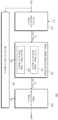
도 2는 도 1의 이미징 시스템(1000)을 상세하게 보여주는 블록도이다. 도 2를 참조하면, 이미징 시스템(1000)은 픽셀 어레이(121), 구동 회로(122), 출력 회로(123), 프로세싱 장치(200) 및 컨트롤러(300)를 포함할 수 있다. 픽셀 어레이(121), 구동 회로(122) 및 출력 회로(123)는 도 1의 이미지 센서(120)에 포함될 수 있다.FIG. 2 is a block diagram showing the
픽셀 어레이(121)는 복수의 행들과 복수의 열들로 이루어진 매트릭스 형태로 배열된 복수의 픽셀들을 포함할 수 있다. 각각의 픽셀들은 광 신호(LS)에 기초하여 전기적인 신호(예를 들어, 아날로그 신호)를 생성할 수 있다. 컬러 이미지를 생성하기 위해, 각각의 픽셀은 R(red) 필터, G(green) 필터 및 B(blue) 필터 중 하나와 결합될 수 있다. R, G, B 컬러 필터들은 특정 패턴(즉, 컬러 필터 배열(CFA; color filter array)의 패턴)에 따라 픽셀 어레이(121)에 배치될 수 있다. 이에 따라, 각각의 픽셀로부터 생성된 전기적인 신호는 각각의 컬러 필터에 대응하는 컬러 값을 포함할 수 있다.The
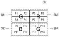
픽셀 어레이(121)는 복수의 픽셀 블록(PB)들을 포함할 수 있다. 각각의 픽셀 블록(PB)은 복수의 픽셀들을 포함할 수 있다. 예를 들어, 픽셀 블록(PB)은 제1 픽셀(P1) 및 제2 픽셀(P2)을 포함할 수 있다. 각각의 픽셀 블록(PB)은 특정 CFA 패턴을 가질 수 있다. 각각의 픽셀 블록(PB)이 특정 CFA 패턴을 가지므로, 복수의 픽셀 블록(PB)들을 포함하는 픽셀 어레이(121)는 반복되는 CFA 패턴을 가질 수 있다. 픽셀 블록(PB)의 CFA 패턴들의 예시는 도 3a 내지 도 3c를 참조하여 설명될 것이다.The
픽셀 블록(PB)은 하나 이상의 픽셀을 포함하는 서브 블록(SB)을 포함할 수 있다. 서브 블록(SB)은 R, G, B 중 동일한 컬러에 대응하는 픽셀들을 포함할 수 있다. 즉, 서브 블록(SB)의 픽셀들에는 동일한 컬러를 가지는 컬러 필터들이 배치될 수 있다.The pixel block (PB) may include a sub-block (SB) including one or more pixels. The subblock SB may include pixels corresponding to the same color among R, G, and B. That is, color filters having the same color may be disposed in pixels of the subblock SB.
구동 회로(122)는 픽셀 어레이(121)의 픽셀들을 제어할 수 있다. 픽셀들을 제어하기 위해, 구동 회로(122)는 제어 신호를 생성할 수 있다. 예를 들어, 구동 회로(122)는 픽셀 어레이(121)에 포함되는 픽셀들을 행 단위로 제어할 수 있다. 제어 신호에 응답하여 픽셀들이 동작할 수 있다.The driving
출력 회로(123)는 픽셀 어레이(121)로부터 출력되는 아날로그 신호를 디지털 신호로 변환할 수 있다. 아날로그 신호는 픽셀 어레이(121)로부터 컬럼 단위로 출력될 수 있다. 출력 회로(123)는 유효 신호 성분을 추출하기 위해 상관 이중 샘플링(CDS; correlated double sampling)을 수행할 수 있다. 출력 회로(123)는 CDS가 수행된 아날로그 신호를 디지털 신호로 변환할 수 있다. 또는, 출력 회로(123)는 디지털 신호에 대하여 CDS를 수행할 수 있다. 이에 따라, 출력 회로(123)는 디지털 신호의 이미지 데이터(IDAT)를 출력할 수 있다. 이미지 데이터(IDAT)는 프로세싱 장치(200) 및 컨트롤러(300)로 제공될 수 있다.The
컨트롤러(300)는 픽셀 어레이(121)의 픽셀들 각각에 대한 노출 시간 정보(ETI)를 결정할 수 있다. 컨트롤러(300)는 복수의 노출 시간을 기준으로 노출 시간 정보(ETI)를 결정할 수 있다. 복수의 노출 시간은 서로 다른 2개 이상의 노출 시간일 수 있다. 예를 들어, 컨트롤러(300)는 제1 픽셀(P1)의 노출 시간 정보(ETI)를 제1 노출 시간으로 결정하고, 제2 픽셀(P2)의 노출 시간 정보(ETI)를 제2 노출 시간으로 결정할 수 있다. 이 경우, 제1 노출 시간은 제2 노출 시간보다 길 수 있다. 또는, 제1 노출 시간은 제2 노출 시간보다 짧을 수 있다.The
컨트롤러(300)는 서로 다른 노출 시간에 대응하는 픽셀들의 개수가 다르게 노출 시간 정보(ETI)를 결정할 수 있다. 예를 들어, 컨트롤러(300)는 제1 노출 시간에 대응하는 픽셀들의 수가 제2 노출 시간에 대응하는 픽셀들의 수보다 크도록 노출 시간 정보(ETI)를 결정할 수 있다.The
컨트롤러(300)는 픽셀 블록(PB) 또는 서브 블록(SB)이 일정한 노출 패턴을 가지도록 노출 시간 정보(ETI)를 결정할 수 있다. 여기서, 노출 패턴은 픽셀들 각각에 대응하는 노출 시간에 따라 형성되는 패턴을 의미한다. 픽셀 블록(PB) 단위로 일정한 노출 패턴이 형성되는 경우, 픽셀 어레이(121)는 픽셀 블록(PB)의 노출 패턴에 따라 반복되는 노출 패턴을 가질 수 있다. 서브 블록(SB) 단위로 일정한 노출 패턴이 형성되는 경우, 픽셀 어레이(121)는 서브 블록(SB)의 노출 패턴에 따라 반복되는 노출 패턴을 가질 수 있다. 예를 들어, 픽셀 블록(PB) 단위로 노출 패턴이 형성되는 경우, 제1 픽셀(P1)은 제1 노출 시간에 대응할 수 있고, 제2 픽셀(P2)은 제2 노출 시간에 대응할 수 있다. 노출 패턴들의 예시는 도 4a 내지 도 4c를 참조하여 설명될 것이다.The
컨트롤러(300)는 HDR 이미지(HDAT)의 다이내믹 레인지를 조절하기 위해 노출 시간 정보(ETI)를 결정할 수 있다. 예를 들어, 컨트롤러(300)는 다이내믹 레인지를 증가시키기 위해 상대적으로 긴 노출 시간을 더 증가시키거나 상대적으로 짧은 노출 시간을 더 감소시킬 수 있다. 예시적으로, 컨트롤러(300)는 이미지 데이터(IDAT)에 기초하여 노출 시간 정보(ETI)를 결정할 수 있다. 예를 들어, 컨트롤러(300)는 이미지 데이터(IDAT)로부터 산출된 다이내믹 레인지에 따라 노출 시간 정보(ETI)를 결정할 수 있다. 노출 시간 정보(ETI)는 구동 회로(122) 및 프로세싱 장치(200)로 제공될 수 있다.The
구동 회로(122)는 노출 시간 정보(ETI)에 따라 픽셀 어레이(121)의 픽셀들 각각을 제어할 수 있다. 예를 들어, 제1 픽셀(P1)의 노출 시간 정보(ETI)가 제1 노출 시간인 경우, 구동 회로(122)는 제1 픽셀(P1)이 제1 노출 시간 동안 동작하도록 제1 픽셀(P1)을 제어할 수 있다. 제2 픽셀(P2)의 노출 시간 정보(ETI)가 제2 노출 시간인 경우, 구동 회로(122)는 제2 픽셀(P2)이 제2 노출 시간 동안 동작하도록 제2 픽셀(P2)을 제어할 수 있다. 예를 들어, 구동 회로(122)는 노출 시간 정보(ETI)에 따라 픽셀들 각각에 포함된 트랜지스터들을 제어할 수 있다. 좀 더 상세한 예로서, 구동 회로(122)는 노출 시간 정보(ETI)에 따라 픽셀들 각각의 트랜스퍼 게이트(transfer gate)의 온(on)/오프(off) 시간을 조절할 수 있다. 이에 따라, 픽셀들 각각은 노출 시간 정보(ETI)에 따라 동작할 수 있다.The driving
출력 회로(123)로부터 출력되는 이미지 데이터(IDAT)는 복수의 노출 시간에 따라 획득될 수 있다. 예를 들어, 이미지 데이터(IDAT) 중 일부는 제1 노출 시간에 대응하는 픽셀들로부터 획득될 수 있고, 일부는 제2 노출 시간에 대응하는 픽셀들로부터 획득될 수 있다. 이 경우, 제1 노출 시간에 대응하는 픽셀들의 개수와 제2 노출 시간에 대응하는 픽셀들의 개수는 다를 수 있다.Image data IDAT output from the
프로세싱 장치(200)는 노출 시간 정보(ETI)를 기반으로 이미지 데이터(IDAT)를 처리하여 HDR 이미지(HDAT)를 생성할 수 있다. 예시적으로, 프로세싱 장치(200)는 이미지 데이터(IDAT)를 노출 시간에 따라 분리할 수 있다. 예를 들어, 이미지 데이터(IDAT)는 제1 노출 시간에 대응하는 픽셀 값들과 제2 노출 시간에 대응하는 픽셀 값들을 포함할 수 있다. 프로세싱 장치(200)는 제1 노출 시간으로 획득된 픽셀 값들과 제2 노출 시간으로 획득된 픽셀 값들을 분리할 수 있다. 프로세싱 장치(200)는 분리된 픽셀 값들을 이용하여 HDR 이미지(HDAT)를 생성할 수 있다. HDR 이미지(HDAT)의 생성과 관련된 자세한 내용은 도 6 내지 도 12를 참조하여 후술될 것이다.The
도 3a 내지 도 3c는 본 발명의 실시 예들에 따른 CFA 패턴의 예시들을 보여주는 도면이다. 도 3a를 참조하면, 픽셀 블록(PB)은 제1 내지 제4 서브 블록들(SB1-SB4)을 포함할 수 있다. 각각의 서브 블록(SB)은 4 개의 픽셀들을 포함할 수 있다. 예를 들어, 제1 서브 블록(SB1)은 제1 내지 제4 픽셀들(P1-P4)을 포함할 수 있다. 픽셀 블록(PB)은 특정 CFA 패턴을 가질 수 있다. 제1 서브 블록(SB1) 및 제4 서브 블록(SB4)은 그린 컬러에 대응하고, 제2 서브 블록(SB2)은 레드 컬러에 대응하고, 제3 서브 블록(SB3)은 블루 컬러에 대응할 수 있다.3A to 3C are diagrams showing examples of CFA patterns according to embodiments of the present invention. Referring to FIG. 3A, the pixel block PB may include first to fourth sub-blocks SB1-SB4. Each subblock (SB) may include 4 pixels. For example, the first sub-block SB1 may include first to fourth pixels P1-P4. A pixel block (PB) may have a specific CFA pattern. The first sub-block SB1 and the fourth sub-block SB4 may correspond to green color, the second sub-block SB2 may correspond to red color, and the third sub-block SB3 may correspond to blue color. .
도 3b를 참조하면, 픽셀 블록(PB)은 제1 내지 제4 서브 블록들(SB1-SB4)을 포함할 수 있다. 각각의 서브 블록(SB)은 9 개의 픽셀들을 포함할 수 있다. 예를 들어, 제1 서브 블록(SB1)은 제1 내지 제9 픽셀들(P1-P9)을 포함할 수 있다. 픽셀 블록(PB)은 특정 CFA 패턴을 가질 수 있다. 제1 서브 블록(SB1) 및 제4 서브 블록(SB4)은 그린 컬러에 대응하고, 제2 서브 블록(SB2)은 레드 컬러에 대응하고, 제3 서브 블록(SB3)은 블루 컬러에 대응할 수 있다.Referring to FIG. 3B, the pixel block PB may include first to fourth sub-blocks SB1-SB4. Each subblock (SB) may include 9 pixels. For example, the first sub-block SB1 may include first to ninth pixels P1-P9. A pixel block (PB) may have a specific CFA pattern. The first sub-block SB1 and the fourth sub-block SB4 may correspond to green color, the second sub-block SB2 may correspond to red color, and the third sub-block SB3 may correspond to blue color. .
도 3c를 참조하면, 픽셀 블록(PB)은 제1 내지 제4 서브 블록들(SB1-SB4)을 포함할 수 있다. 각각의 서브 블록(SB)은 하나의 픽셀을 포함할 수 있다. 예를 들어, 제1 서브 블록(SB1)은 제1 픽셀(P1)을 포함할 수 있다. 픽셀 블록(PB)은 특정 CFA 패턴을 가질 수 있다. 제1 서브 블록(SB1) 및 제4 서브 블록(SB4)은 그린 컬러에 대응하고, 제2 서브 블록(SB2)은 레드 컬러에 대응하고, 제3 서브 블록(SB3)은 블루 컬러에 대응할 수 있다. 도 3c의 CFA 패턴은 베이어 패턴(Bayer pattern)일 수 있다.Referring to FIG. 3C, the pixel block PB may include first to fourth sub-blocks SB1-SB4. Each subblock SB may include one pixel. For example, the first sub-block SB1 may include the first pixel P1. A pixel block (PB) may have a specific CFA pattern. The first sub-block SB1 and the fourth sub-block SB4 may correspond to green color, the second sub-block SB2 may correspond to red color, and the third sub-block SB3 may correspond to blue color. . The CFA pattern in FIG. 3C may be a Bayer pattern.
도 3a 내지 도 3c의 CFA 패턴들에 따르면, 그린 컬러에 대응하는 픽셀들의 개수, 레드 컬러에 대응하는 픽셀들의 개수, 블루 컬러에 대응하는 픽셀들의 개수는 각각 전체 픽셀들 중 50%, 25%, 25%일 수 있다. 그러나, 본 발명이 이에 한정되는 것은 아니며, 그린 컬러, 레드 컬러 및 블루 컬러에 대응하는 픽셀들의 비율은 달라질 수 있다.According to the CFA patterns of FIGS. 3A to 3C, the number of pixels corresponding to the green color, the number of pixels corresponding to the red color, and the number of pixels corresponding to the blue color are respectively 50%, 25%, and 50% of all pixels, respectively. It could be 25%. However, the present invention is not limited to this, and the ratio of pixels corresponding to green color, red color, and blue color may vary.
도 3a는 4 개의 픽셀들이 동일한 컬러에 대응하고, 도 3b는 9 개의 픽셀들이 동일한 컬러에 대응하는 것으로 도시되었지만, 본 발명은 이에 한정되지 않는다. 예를 들어, 픽셀 블록(PB)은 다양한 개수의 픽셀들을 포함할 수 있고, 동일한 컬러에 대응하는 서브 블록(SB)은 다양한 개수의 픽셀들을 포함할 수 있다.Although FIG. 3A shows 4 pixels corresponding to the same color and FIG. 3B shows 9 pixels corresponding to the same color, the present invention is not limited thereto. For example, the pixel block PB may include a varying number of pixels, and the subblock SB corresponding to the same color may include a varying number of pixels.
상술한 바와 같이, 본 발명의 실시 예들에 따른 CFA 패턴은, 도 3a 내지 도 3b에 도시된 바와 같이, 동일한 컬러에 대응하는 복수의 픽셀들이 인접하도록 형성될 수 있거나, 도 3c에 도시된 바와 같이, 서로 다른 컬러에 대응하는 픽셀들이 교차되도록 형성될 수 있다.As described above, the CFA pattern according to embodiments of the present invention may be formed so that a plurality of pixels corresponding to the same color are adjacent, as shown in FIGS. 3A to 3B, or as shown in FIG. 3C. , pixels corresponding to different colors may be formed to intersect.
도 4a 내지 도 4c는 본 발명의 실시 예들에 따른 노출 패턴의 예시들을 보여준다. 도 4a 내지 도 4c에 도시된 노출 패턴들은 예시들일 뿐이며, 본 발명이 이에 한정되는 것은 아니다. 즉, 픽셀 어레이(121)는 도 4a 내지 도 4c에 도시되지 않은 다양한 노출 패턴들을 가질 수 있다.4A to 4C show examples of exposure patterns according to embodiments of the present invention. The exposure patterns shown in FIGS. 4A to 4C are only examples, and the present invention is not limited thereto. That is, the
도 4a를 참조하면, 4 개의 픽셀들(P1-P4)이 하나의 노출 패턴을 형성할 수 있다. 제1 내지 제3 픽셀들(P1-P3)은 제1 노출 시간에 대응하고, 제4 픽셀(P4)은 제2 노출 시간에 대응할 수 있다. 즉, 2 개의 노출 시간을 기반으로 노출 패턴이 형성될 수 있다. 예를 들어, 제1 노출 시간은 제2 노출 시간보다 길 수 있다. 제1 노출 시간에 대응하는 픽셀들(P1-P3)의 개수는 제2 노출 시간에 대응하는 픽셀(P4)의 개수보다 클 수 있다. 예를 들어, 도 3a의 서브 블록(SB) 또는 도 3c의 픽셀 블록(PB)은 도 4a의 노출 패턴을 가질 수 있다.Referring to FIG. 4A, four pixels (P1-P4) may form one exposure pattern. The first to third pixels (P1-P3) may correspond to the first exposure time, and the fourth pixel (P4) may correspond to the second exposure time. That is, an exposure pattern can be formed based on two exposure times. For example, the first exposure time may be longer than the second exposure time. The number of pixels (P1-P3) corresponding to the first exposure time may be greater than the number of pixels (P4) corresponding to the second exposure time. For example, the subblock SB of FIG. 3A or the pixel block PB of FIG. 3C may have the exposure pattern of FIG. 4A.
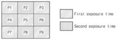
도 4b를 참조하면, 9개의 픽셀들(P1-P9)이 하나의 노출 패턴을 형성할 수 있다. 제1 픽셀(P1), 제3 픽셀(P3), 제5 픽셀(P5), 제7 픽셀(P7) 및 제9 픽셀(P9)은 제1 노출 시간에 대응하고, 제2 픽셀(P2), 제4 픽셀(P4), 제6 픽셀(P6) 및 제8 픽셀(P8)은 제2 노출 시간에 대응할 수 있다. 제1 노출 시간에 대응하는 픽셀들의 개수는 제2 노출 시간에 대응하는 픽셀들의 개수보다 클 수 있다. 예를 들어, 도 3b의 서브 블록(SB)은 도 4b의 노출 패턴을 가질 수 있다.Referring to FIG. 4B, nine pixels (P1-P9) may form one exposure pattern. The first pixel (P1), the third pixel (P3), the fifth pixel (P5), the seventh pixel (P7), and the ninth pixel (P9) correspond to the first exposure time, the second pixel (P2), The fourth pixel P4, sixth pixel P6, and eighth pixel P8 may correspond to the second exposure time. The number of pixels corresponding to the first exposure time may be greater than the number of pixels corresponding to the second exposure time. For example, the subblock SB of FIG. 3B may have the exposure pattern of FIG. 4B.
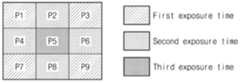
도 4c를 참조하면, 9개의 픽셀들(P1-P9)이 하나의 노출 패턴을 형성할 수 있다. 제1 픽셀(P1), 제3 픽셀(P3), 제7 픽셀(P7) 및 제9 픽셀(P9)은 제1 노출 시간에 대응하고, 제2 픽셀(P2), 제4 픽셀(P4), 제6 픽셀(P6) 및 제8 픽셀(P8)은 제2 노출 시간에 대응하고, 제5 픽셀(P5)은 제3 노출 시간에 대응할 수 있다. 즉, 3 개의 노출 시간을 기반으로 노출 패턴이 형성될 수 있다. 예를 들어, 제1 노출 시간, 제2 노출 시간 및 제3 노출 시간의 순서로 노출 시간이 짧아질 수 있다. 제1 노출 시간에 대응하는 픽셀들의 수 및 제2 노출 시간에 대응하는 픽셀들의 수는 제3 노출 시간에 대응하는 픽셀의 수보다 클 수 있다. 예를 들어, 도 3b의 서브 블록(SB)은 도 4c의 노출 패턴을 가질 수 있다.Referring to FIG. 4C, nine pixels (P1-P9) may form one exposure pattern. The first pixel (P1), the third pixel (P3), the seventh pixel (P7), and the ninth pixel (P9) correspond to the first exposure time, the second pixel (P2), the fourth pixel (P4), The sixth pixel P6 and the eighth pixel P8 may correspond to the second exposure time, and the fifth pixel P5 may correspond to the third exposure time. That is, an exposure pattern can be formed based on three exposure times. For example, the exposure time may be shortened in the order of the first exposure time, the second exposure time, and the third exposure time. The number of pixels corresponding to the first exposure time and the number of pixels corresponding to the second exposure time may be greater than the number of pixels corresponding to the third exposure time. For example, the subblock SB of FIG. 3B may have the exposure pattern of FIG. 4C.
상술한 바와 같이, 본 발명의 실시 예들에 따른 노출 패턴에 따르면, 서로 다른 노출 시간에 대응하는 픽셀들의 수는 다를 수 있다. 즉, 각각의 노출 시간에 대응하는 픽셀들의 개수는 동일하지 않을 수 있다.As described above, according to exposure patterns according to embodiments of the present invention, the number of pixels corresponding to different exposure times may be different. That is, the number of pixels corresponding to each exposure time may not be the same.
도 4a 내지 도 4c에는 2 개의 노출 시간 또는 3 개의 노출 시간에 따른 노출 패턴들이 도시되었지만, 본 발명은 이에 한정되지 않는다. 예를 들어, 4 개 이상의 노출 시간을 기반으로 노출 패턴이 형성될 수 있다. 이 경우, 서로 다른 노출 시간에 대응하는 픽셀들의 수가 달라지도록 노출 패턴이 형성될 수 있다.4A to 4C show exposure patterns according to two or three exposure times, but the present invention is not limited thereto. For example, an exposure pattern may be formed based on four or more exposure times. In this case, an exposure pattern may be formed so that the number of pixels corresponding to different exposure times varies.
도 5a 및 도 5b는 본 발명의 실시 예들에 따른 노출 시간에 따라 도 2의 이미징 시스템(1000)이 픽셀들을 제어하는 예시들을 보여준다. 도 2 및 도 5a를 참조하면, 구동 회로(122)는 제1 노출 시간 및 제1 노출 시간보다 짧은 제2 노출 시간에 따라 픽셀들을 제어할 수 있다. 구동 회로(122)는 제1 시간(t1)부터 제3 시간(t3)까지 제1 노출 시간에 대응하는 픽셀들을 제어할 수 있고, 제2 시간(t2)부터 제3 시간(t3)까지 제2 노출 시간에 대응하는 픽셀들을 제어할 수 있다. 예를 들어, 구동 회로(122)는 제1 시간(t1) 및 제3 시간(t3)에 따라 제1 노출 시간에 대응하는 픽셀들 각각의 트랜스퍼 게이트의 온/오프 시간을 제어할 수 있다.FIGS. 5A and 5B show examples of how the
도 2 및 도 5b를 참조하면, 구동 회로(122)는 제1 노출 시간, 제1 노출 시간보다 짧은 제2 노출 시간 및 제2 노출 시간보다 짧은 제3 노출 시간에 따라 픽셀들을 제어할 수 있다. 구동 회로(122)는 제1 시간(t1)부터 제4 시간(t4)까지 제1 노출 시간에 대응하는 픽셀들을 제어할 수 있고, 제2 시간(t2)부터 제4 시간(t4)까지 제2 노출 시간에 대응하는 픽셀들을 제어할 수 있고, 제3 시간(t3)부터 제4 시간(t4)까지 제3 노출 시간에 대응하는 픽셀들을 제어할 수 있다. 예를 들어, 구동 회로(122)는 제1 시간(t1) 및 제4 시간(t4)에 따라 제1 노출 시간에 대응하는 픽셀들 각각의 트랜스퍼 게이트의 온/오프 시간을 제어할 수 있다.Referring to FIGS. 2 and 5B , the driving
도 5a 및 도 5b에 도시된 바와 같이, 구동 회로(122)는 픽셀들 각각의 트랜스퍼 게이트의 온/오프 시간을 제어하여 픽셀들의 노출 시간을 다르게 할 수 있다. 이 경우, 구동 회로(122)는 픽셀들 각각의 트랜스퍼 게이트의 오프 시간이 동일하도록 픽셀들을 제어할 수 있다. 그러나, 본 발명은 이에 한정되지 않으며, 구동 회로(122)는 픽셀들 각각의 트랜스퍼 게이트의 온/오프 시간을 다르게 제어하여 픽셀들의 노출 시간을 다르게 할 수 있다.As shown in FIGS. 5A and 5B, the driving
이하에서는 도 6 내지 도 12를 참조하여 도 2의 프로세싱 장치(200)가 HDR 이미지(HDAT)를 생성하는 동작을 설명할 것이다. 설명의 편의를 위해, 도 4a 또는 도 4b에 도시된 바와 같이, 2 개의 노출 시간 또는 3 개의 노출 시간에 따라 획득된 이미지 데이터(IDAT)를 기반으로 프로세싱 장치(200)가 HDR 이미지(HDAT)를 생성하는 것으로 가정한다. 그러나, 본 발명이 이에 한정되는 것은 아니며, 프로세싱 장치(200)는 4 개 이상의 노출 시간에 따라 획득된 이미지 데이터(IDAT)를 기반으로 HDR 이미지(HDAT)를 생성할 수 있다.Hereinafter, an operation of the
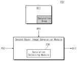
도 6은 도 2의 프로세싱 장치(200)의 하나의 예시를 보여주는 블록도이다. 구체적으로, 도 6은 2 개의 노출 시간에 따라 획득된 이미지 데이터(IDAT)를 기반으로 HDR 이미지(HDAT)를 생성하는 프로세싱 장치(200)를 나타낸다. 도 6을 참조하면, 프로세싱 장치(200)는 패턴 분리 모듈(210), 모션 추정 모듈(220), 베이어 이미지 생성 블록(230) 및 이미지 재구성 모듈(240)을 포함할 수 있다. 베이어 이미지 생성 블록(230)은 제1 베이어 이미지 생성 모듈(231) 및 제2 베이어 이미지 생성 모듈(232)을 포함할 수 있다.FIG. 6 is a block diagram showing an example of the
프로세싱 장치(200)의 각각의 모듈들은 소프트웨어, 또는 하드웨어, 또는 그것들의 조합의 형태로 구현될 수 있다. 예를 들어, 소프트웨어는 기계 코드, 펌웨어, 임베디드 코드 및 애플리케이션 소프트웨어일 수 있다. 예를 들어, 하드웨어는 전기 회로, 전자 회로, 프로세서, 집적 회로, 집적 회로 코어들, 멤즈(Micro Electro Mechanical System; MEMS) 또는 그것들의 조합일 수 있다.Each module of the
패턴 분리 모듈(210)은 픽셀들 각각에 대한 노출 시간 정보(ETI)를 기반으로 이미지 데이터(IDAT)를 분리할 수 있다. 패턴 분리 모듈(210)은 이미지 데이터(IDAT)에서 동일한 노출 시간에 대응하는 픽셀 값들을 분리할 수 있다. 예를 들어, 패턴 분리 모듈(210)은 제1 노출 시간에 대응하는 제1 픽셀 값들(PX1) 및 제2 노출 시간에 대응하는 제2 픽셀 값들(PX2)을 분리할 수 있다. 이 경우, 제1 픽셀 값들(PX1)에 대응하는 픽셀들의 수는 제2 픽셀 값들(PX2)에 대응하는 픽셀들의 수보다 클 수 있다. 분리된 픽셀 값들(PX)은 베이어 이미지 생성 블록(230)으로 제공될 수 있다.The
모션 추정 모듈(220)은 이미지 데이터(IDAT)를 기반으로 모션 정보(MI)를 추정할 수 있다. 모션 정보(MI)는 하나의 프레임에 대한 이미지 데이터(IDAT)가 획득되는 동안 프레임 상의 피사체의 움직임의 크기를 나타낼 수 있다. 예를 들어, 피사체의 움직임이 큰 경우의 모션 정보(MI)는 피사체의 움직임이 작은 경우의 모션 정보(MI)보다 클 수 있다. 피사체의 움직임의 크기는 영역(또는, 픽셀) 별로 다를 수 있다. 예를 들어, 모션 추정 모듈(220)은 특정 영역에서 이미지 데이터(IDAT)의 제1 픽셀 값들(PX1)과 제2 픽셀 값들(PX2)을 비교하여 특정 영역에서의 모션 정보(MI)를 추정할 수 있다. 모션 추정 모듈(220)은 제1 픽셀 값들(PX1)과 제2 픽셀 값들(PX2)이 동일한 휘도를 갖도록 픽셀 값들을 보정할 수 있다. 보정 후, 모션 추정 모듈(220)은 제1 픽셀 값들(PX1)과 제2 픽셀 값들(PX2)의 차이를 기반으로 모션 정보(MI)를 추정할 수 있다. 그러나, 본 발명은 이에 한정되지 않으며, 모션 추정 모듈(220)은 다양한 방법에 기초하여 모션 정보(MI)를 추정할 수 있다.The
예시적으로, 피사체의 움직임을 감지하는 모션 감지 센서가 존재하는 경우, 모션 추정 모듈(220)은 모션 감지 센서로부터 출력된 센싱 정보를 추가적으로 반영하여 모션 정보(MI)를 추정할 수 있다. 모션 정보(MI)는 베이어 이미지 생성 블록(230) 및 이미지 재구성 모듈(240)로 제공될 수 있다.As an example, if there is a motion detection sensor that detects movement of a subject, the
베이어 이미지 생성 블록(230)은 픽셀 값들(PX)을 기반으로 베이어 이미지(BI)를 생성할 수 있다. 베이어 이미지(BI)는 도 3c에 도시된 바와 같이, 베이어 패턴을 가지는 이미지일 수 있다.The Bayer
제1 베이어 이미지 생성 모듈(231)은 제1 픽셀 값들(PX1)을 기반으로 제1 베이어 이미지(BI1)를 생성할 수 있다. 예를 들어, 제1 베이어 이미지 생성 모듈(231)은 제1 픽셀 값들(PX1)을 이용하여 보간 이미지를 생성하고, 보간 이미지를 베이어 패턴으로 변환하여 제1 베이어 이미지(BI1)를 생성할 수 있다. 제1 베이어 이미지(BI1)는 제1 노출 시간에 대응하는 픽셀 값들만을 포함할 수 있다.The first Bayer
예시적으로, 제1 베이어 이미지 생성 모듈(231)은 제1 베이어 이미지(BI1)를 생성하기 위해 제2 픽셀 값들(PX2) 및 모션 정보(MI)를 추가로 이용할 수 있다. 이 경우, 제1 베이어 이미지 생성 모듈(231)은 모션 정보(MI)에 따라 제1 픽셀 값들(PX1)의 가중치와 제2 픽셀 값들(PX2)의 가중치를 결정할 수 있다. 제1 베이어 이미지 생성 모듈(231)은 가중치들에 따라 제1 픽셀 값들(PX1) 및 제2 픽셀 값들(PX2)을 이용하여 제1 베이어 이미지(BI1)를 생성할 수 있다.As an example, the first Bayer
제2 베이어 이미지 생성 모듈(232)은 제2 픽셀 값들(PX2) 및 제1 베이어 이미지(BI1)를 기반으로 제2 베이어 이미지(BI2)를 생성할 수 있다. 예를 들어, 제2 베이어 이미지 생성 모듈(232)은 제2 픽셀 값들(PX2)과 제1 베이어 이미지(BI1)의 픽셀 값들을 이용하여 제2 베이어 이미지(BI2)의 픽셀 값들을 보간할 수 있다. 제2 베이어 이미지 생성 모듈(232)은 제2 픽셀 값들(PX2)의 가중치와 제1 베이어 이미지(BI1)의 픽셀 값들의 가중치에 따라 제2 베이어 이미지(BI2)의 픽셀 값들을 보간할 수 있다. 제2 픽셀 값들(PX2)의 가중치와 제1 베이어 이미지(BI1)의 픽셀 값들의 가중치는 모션 정보(MI)에 따라 결정될 수 있다. 예를 들어, 모션 정보(MI)가 큰 영역에서, 제2 픽셀 값들(PX2)의 가중치는 제1 베이어 이미지(BI1)의 픽셀 값들의 가중치보다 크게 결정될 수 있다. 제2 베이어 이미지(BI2)는 제2 노출 시간에 대응하는 픽셀 값들만을 포함할 수 있다. 예시적으로, 제2 베이어 이미지 생성 모듈(232)은 제2 베이어 이미지(BI2)를 생성하기 위해 제1 픽셀 값들(PX1)을 추가로 이용할 수 있다.The second Bayer
이미지 재구성 모듈(240)은 제1 및 제2 베이어 이미지들(BI1, BI2)에 기초하여 HDR 이미지(HDAT)를 생성할 수 있다. 예를 들어, 이미지 재구성 모듈(240)은 제1 베이어 이미지(BI1)의 가중치 및 제2 베이어 이미지(BI2)의 가중치에 따라 제1 베이어 이미지(BI1) 및 제2 베이어 이미지(BI2)를 합성할 수 있다. 각각의 가중치는 모션 정보(MI)에 따라 결정될 수 있다. 예를 들어, 모션 정보(MI)가 큰 영역에서, 제1 베이어 이미지(BI1)의 가중치는 제2 베이어 이미지(BI2)의 가중치보다 작게 결정될 수 있다.The
상술한 바와 같이, 본 발명의 하나의 실시 예에 따른 프로세싱 장치(200)는 제1 노출 시간에 대응하는 제1 픽셀 값들(PX1)을 기반으로 제1 베이어 이미지(BI1)를 생성할 수 있다. 제1 픽셀 값들(PX1)에 대응하는 픽셀들의 수는 제2 픽셀 값들(PX2)에 대응하는 픽셀들의 수보다 크므로, 제1 픽셀 값들(PX1)을 기반으로 생성된 제1 베이어 이미지(BI1)는 선명도가 상대적으로 높을 수 있다. 제1 베이어 이미지(BI1)를 기반으로 생성된 제2 베이어 이미지(BI2)의 선명도 또한 상대적으로 높을 수 있다. 이에 따라, 제1 베이어 이미지(BI1) 및 제2 베이어 이미지(BI2)를 기반으로 생성된 HDR 이미지(HDAT)의 선명도는 상대적으로 높을 수 있다. 즉, HDR 이미지(HDAT)의 화질이 향상될 수 있다. 또한, 프로세싱 장치(200)는 피사체의 모션 정보(MI)를 반영하여 베이어 이미지들(BI1, BI2) 및 HDR 이미지(HDAT)를 생성할 수 있다. 따라서, HDR 이미지(HDAT)에 피사체의 움직임에 따른 결함 발생 가능성이 감소될 수 있다.As described above, the
도 7은 도 6의 프로세싱 장치(200)의 동작에 따라 생성되는 이미지들의 예시를 보여주는 도면이다. 도 6 및 도 7을 참조하면, 프로세싱 장치(200)는 시간에 따라 이미지 데이터(IDAT)를 기반으로 다양한 이미지 데이터를 생성할 수 있다.FIG. 7 is a diagram showing examples of images generated according to the operation of the
패턴 분리 모듈(210)은 이미지 데이터(IDAT)를 수신할 수 있다. 이미지 데이터(IDAT)는 도 3a의 CFA 패턴을 가지는 픽셀들(P1-P16)로부터 획득된 픽셀 값들(V1-V16)을 포함할 수 있다. 픽셀 값들(V1-V16)은 도 4a의 노출 패턴에 기초하여 획득될 수 있다. 여기서, 픽셀 값들(V1-V36)은 픽셀들(P1-P36)의 픽셀 값일 수 있다.The
패턴 분리 모듈(210)은 이미지 데이터(IDAT)에서 제1 픽셀 값들(PX1)과 제2 픽셀 값들(PX2)을 분리할 수 있다. 제1 픽셀 값들(PX1)은 제1 노출 시간에 대응하는 12 개의 픽셀 값들을 포함하고, 제2 픽셀 값들(PX2)은 제2 노출 시간에 대응하는 4 개의 픽셀 값들을 포함할 수 있다.The
제1 베이어 이미지 생성 모듈(231)은 제1 픽셀 값들(PX1)을 기반으로 보간 이미지(ITI)를 생성할 수 있다. 제1 베이어 이미지 생성 모듈(231)은 제1 픽셀 값들(PX1)을 이용하여 보간 이미지(ITI)의 픽셀 값들(T1-T16)을 보간할 수 있다. 여기서, 픽셀 값들(T1-T16)은 픽셀들(P1-P16)에 대응하는 위치의 픽셀 값일 수 있다.The first Bayer
제1 베이어 이미지 생성 모듈(231)은 보간 이미지(ITI)를 변환하여 베이어 패턴을 가지는 제1 베이어 이미지(BI1)를 생성할 수 있다. 이 경우, 제1 베이어 이미지(BI1)의 픽셀 값들(M1-M16)은 제1 노출 시간에 대응할 수 있다. 여기서, 픽셀 값들(M1-M16)은 픽셀들(P1-P16)에 대응하는 위치의 픽셀 값일 수 있다.The first Bayer
제2 베이어 이미지 생성 모듈(232)은 제2 픽셀 값들(PX2)과 제1 베이어 이미지(BI1)의 픽셀 값들(M1-M16)을 기반으로 제2 베이어 이미지(BI2)를 생성할 수 있다. 제2 베이어 이미지 생성 모듈(232)은 제2 베이어 이미지(BI2)가 베이어 패턴을 가지도록 제2 베이어 이미지(BI2)의 픽셀 값들(N1-N16)을 보간할 수 있다. 여기서, 픽셀 값들(N1-N16)은 픽셀들(P1-P16)에 대응하는 위치의 픽셀 값일 수 있다. 이 경우, 제2 베이어 이미지(BI2)의 픽셀 값들(N1-N16)은 제2 노출 시간에 대응할 수 있다.The second Bayer
도 7에는 제2 베이어 이미지(BI2)가 보간을 통해 바로 생성되는 것으로 도시되었지만, 본 발명은 이에 한정되지 않는다. 예를 들어, 제1 베이어 이미지(BI1)와 같이, 보간을 통해 보간 이미지가 생성되고, 보간 이미지가 베이어 패턴으로 변환되어 제2 베이어 이미지(BI2)가 생성될 수 있다.Although FIG. 7 shows that the second Bayer image BI2 is directly generated through interpolation, the present invention is not limited to this. For example, like the first Bayer image BI1, an interpolation image may be generated through interpolation, and the interpolation image may be converted into a Bayer pattern to generate the second Bayer image BI2.
이미지 재구성 모듈(240)은 제1 베이어 이미지(BI1) 및 제2 베이어 이미지(BI2)를 합성하여 HDR 이미지(HDAT)의 픽셀 값들(H1-H16)을 생성할 수 있다. 이에 따라, 베이어 패턴의 HDR 이미지(HDAT)가 생성될 수 있다.The
도 7에 도시된 바와 같이, 제1 베이어 이미지(BI1) 및 제2 베이어 이미지(BI2)의 해상도는 이미지 데이터(IDAT)의 해상도와 동일할 수 있다. 이미지 데이터(IDAT)의 해상도는 픽셀 어레이(121)의 픽셀들의 수와 동일할 수 있다. 즉, 제1 베이어 이미지(BI1)의 해상도 및 제2 베이어 이미지(BI2)의 해상도는 이미지 센서(120)의 해상도와 동일할 수 있다. 또한, 제1 베이어 이미지(BI1) 및 제2 베이어 이미지(BI2)로부터 생성되는 HDR 이미지(HDAT)의 해상도는 이미지 센서(120)의 해상도와 동일할 수 있다. 따라서, 프로세싱 장치(200)는 해상도가 감소되지 않는 고해상도의 HDR 이미지(HDAT)를 생성할 수 있다.As shown in FIG. 7 , the resolution of the first Bayer image BI1 and the second Bayer image BI2 may be the same as the resolution of the image data IDAT. The resolution of the image data IDAT may be equal to the number of pixels of the
도 8은 도 2의 프로세싱 장치(200)의 하나의 예시를 보여주는 블록도이다. 구체적으로, 도 8은 3 개의 노출 시간에 따라 획득된 이미지 데이터(IDAT)를 기반으로 HDR 이미지(HDAT)를 생성하는 프로세싱 장치(200)를 나타낸다. 도 8을 참조하면, 프로세싱 장치(200)는 패턴 분리 모듈(210), 모션 추정 모듈(220), 베이어 이미지 생성 블록(230) 및 이미지 재구성 모듈(240)을 포함할 수 있다. 베이어 이미지 생성 블록(230)은 제1 베이어 이미지 생성 모듈(233), 제2 베이어 이미지 생성 모듈(234) 및 제3 베이어 이미지 생성 모듈(235)을 포함할 수 있다.FIG. 8 is a block diagram showing an example of the
도 8의 패턴 분리 모듈(210), 모션 추정 모듈(220), 베이어 이미지 생성 블록(230) 및 이미지 재구성 모듈(240)은 도 6의 패턴 분리 모듈(210), 모션 추정 모듈(220), 베이어 이미지 생성 블록(230) 및 이미지 재구성 모듈(240)과 실질적으로 동일 또는 유사하게 동작할 수 있으므로, 중복되는 설명은 생략될 수 있다.The
패턴 분리 모듈(210)은 노출 시간 정보(ETI)를 기반으로 이미지 데이터(IDAT)에서 제1 노출 시간에 대응하는 제1 픽셀 값들(PX1), 제2 노출 시간에 대응하는 제2 픽셀 값들(PX2) 및 제3 노출 시간에 대응하는 제3 픽셀 값들(PX3)을 분리할 수 있다. 제1 픽셀 값들(PX1)에 대응하는 픽셀들의 수는 제3 픽셀 값들(PX3)에 대응하는 픽셀들의 수보다 클 수 있다. 제2 픽셀 값들(PX2)에 대응하는 픽셀들의 수는 제1 픽셀 값들(PX1)에 대응하는 픽셀들의 수 이하이고, 제3 픽셀 값들(PX3)에 대응하는 픽셀들의 수 이상일 수 있다. 즉, 각각의 픽셀 값들(PX)에 대응하는 픽셀들의 수는 모두 다르거나, 두 픽셀 값들(PX)(예를 들어, 제1 픽셀 값들(PX1) 및 제2 픽셀 값들(PX2))에 대응하는 픽셀들의 수는 동일하고 나머지 픽셀 값들(PX)(예를 들어, 제3 픽셀 값들(PX3))에 대응하는 픽셀들의 수는 다를 수 있다. 분리된 픽셀 값들(PX)은 베이어 이미지 생성 블록(230)으로 제공될 수 있다.The
모션 추정 모듈(220)은 이미지 데이터(IDAT)를 기반으로 모션 정보(MI)를 추정할 수 있다. 모션 정보(MI)는 제1 모션 정보(MI1)와 제2 모션 정보(MI2)를 포함할 수 있다. 제1 모션 정보(MI1)는 이미지 데이터(IDAT) 중 제1 픽셀 값들(PX1)과 제2 픽셀 값들(PX2)을 기반으로 추정되고, 제2 모션 정보(MI2)는 이미지 데이터(IDAT) 중 제2 픽셀 값들(PX2)과 제3 픽셀 값들(PX3)을 기반으로 추정될 수 있다. 모션 추정 모듈(220)은 모션 정보(MI)를 베이어 이미지 생성 블록(230) 및 이미지 재구성 모듈(240)로 제공할 수 있다.The
제1 베이어 이미지 생성 모듈(233)은 제1 픽셀 값들(PX1)을 기반으로 제1 베이어 이미지(BI1)를 생성할 수 있다. 예를 들어, 제1 베이어 이미지 생성 모듈(233)은 제1 픽셀 값들(PX1)을 이용하여 보간 이미지를 생성하고, 보간 이미지를 베이어 패턴으로 변환하여 제1 베이어 이미지(BI1)를 생성할 수 있다. 제1 베이어 이미지(BI1)는 제1 노출 시간에 대응하는 픽셀 값들만을 포함할 수 있다.The first Bayer
예시적으로, 제1 베이어 이미지 생성 모듈(233)은 제1 베이어 이미지(BI1)를 생성하기 위해 제2 픽셀 값들(PX2) 및 제1 모션 정보(MI1)를 추가로 이용할 수 있다. 이 경우, 제1 베이어 이미지 생성 모듈(233)은 제1 모션 정보(MI1)에 따라 제1 픽셀 값들(PX1)의 가중치와 제2 픽셀 값들(PX2)의 가중치를 결정할 수 있다. 제1 베이어 이미지 생성 모듈(233)은 가중치들에 따라 제1 픽셀 값들(PX1) 및 제2 픽셀 값들(PX2)을 이용하여 제1 베이어 이미지(BI1)를 생성할 수 있다.As an example, the first Bayer
제2 베이어 이미지 생성 모듈(234)은 제2 픽셀 값들(PX2) 및 제1 베이어 이미지(BI1)를 기반으로 제2 베이어 이미지(BI2)를 생성할 수 있다. 예를 들어, 제2 베이어 이미지 생성 모듈(234)은 제2 픽셀 값들(PX2)과 제1 베이어 이미지(BI1)의 픽셀 값들을 이용하여 제2 베이어 이미지(BI2)의 픽셀 값들을 보간할 수 있다. 제2 베이어 이미지 생성 모듈(234)은 제2 픽셀 값들(PX2)의 가중치와 제1 베이어 이미지(BI1)의 픽셀 값들의 가중치에 따라 제2 베이어 이미지(BI2)의 픽셀 값들을 보간할 수 있다. 제2 픽셀 값들(PX2)의 가중치와 제1 베이어 이미지(BI1)의 픽셀 값들의 가중치는 제1 모션 정보(MI1)에 따라 결정될 수 있다. 예를 들어, 제1 모션 정보(MI1)가 큰 영역에서, 제2 픽셀 값들(PX2)의 가중치는 제1 베이어 이미지(BI1)의 픽셀들의 가중치보다 크게 결정될 수 있다. 제2 베이어 이미지(BI2)는 제2 노출 시간에 대응하는 픽셀 값들만을 포함할 수 있다. 예시적으로, 제2 베이어 이미지 생성 모듈(234)은 제2 베이어 이미지(BI2)를 생성하기 위해 제1 픽셀 값들(PX1)을 추가로 이용할 수 있다.The second Bayer
제3 베이어 이미지 생성 모듈(235)은 제3 픽셀 값들(PX3) 및 제2 베이어 이미지(BI2)를 기반으로 제3 베이어 이미지(BI3)를 생성할 수 있다. 예를 들어, 제3 베이어 이미지 생성 모듈(235)은 제3 픽셀 값들(PX3)과 제2 베이어 이미지(BI2)의 픽셀 값들을 이용하여 제3 베이어 이미지(BI3)의 픽셀 값들을 보간할 수 있다. 제3 베이어 이미지 생성 모듈(235)은 제3 픽셀 값들(PX3)의 가중치와 제2 베이어 이미지(BI2)의 픽셀 값들의 가중치에 따라 제3 베이어 이미지(BI3)의 픽셀 값들을 보간할 수 있다. 제3 픽셀 값들(PX3)의 가중치와 제2 베이어 이미지(BI2)의 픽셀 값들의 가중치는 제2 모션 정보(MI2)에 따라 결정될 수 있다. 예를 들어, 제2 모션 정보(MI2)가 큰 영역에서, 제3 픽셀 값들(PX3)의 가중치는 제2 베이어 이미지(BI2)의 가중치보다 크게 결정될 수 있다. 제3 베이어 이미지(BI3)는 제3 노출 시간에 대응하는 픽셀 값들만을 포함할 수 있다. 예시적으로, 제3 베이어 이미지 생성 모듈(235)은 제3 베이어 이미지(BI3)를 생성하기 위해 제2 픽셀 값들(PX2)을 추가로 이용할 수 있다.The third Bayer
이미지 재구성 모듈(240)은 제1 내지 제3 베이어 이미지들(BI1, BI2, BI3)에 기초하여 HDR 이미지(HDAT)를 생성할 수 있다. 예를 들어, 이미지 재구성 모듈(240)은 제1 베이어 이미지(BI1)의 가중치, 제2 베이어 이미지(BI2)의 가중치 및 제3 베이어 이미지(BI3)의 가중치에 따라 제1 내지 제3 베이어 이미지들(BI1-BI3)을 합성할 수 있다. 각각의 가중치는 제1 모션 정보(MI1) 및 제2 모션 정보(MI2)에 따라 결정될 수 있다.The
상술한 바와 같이, 본 발명의 하나의 실시 예에 따른 프로세싱 장치(200)는 이전에 생성된 베이어 이미지를 이용하여 각각의 노출 시간에 대응하는 베이어 이미지를 순차적으로 생성할 수 있다. 프로세싱 장치(200)는 다양한 노출 시간에 대응하는 베이어 이미지들을 기반으로 HDR 이미지(HDAT)를 생성할 수 있다. 이에 따라, 프로세싱 장치(200)는 밝기가 세밀하게 조절된 HDR 이미지(HDAT)를 생성할 수 있다.As described above, the
도 9는 도 8의 프로세싱 장치(200)의 동작에 따라 생성되는 이미지들의 예시를 보여주는 도면이다. 도 8 및 도 9를 참조하면, 프로세싱 장치(200)는 시간에 따라 이미지 데이터(IDAT)를 기반으로 다양한 이미지 데이터를 생성할 수 있다.FIG. 9 is a diagram showing examples of images generated according to the operation of the
패턴 분리 모듈(210)은 이미지 데이터(IDAT)를 수신할 수 있다. 이미지 데이터(IDAT)는 도 3b의 CFA 패턴을 가지는 픽셀들(P1-P36)로부터 획득된 픽셀 값들(V1-V36)을 포함할 수 있다. 픽셀 값들(V1-V36)은 도 4c의 노출 패턴에 기초하여 획득될 수 있다. 여기서, 픽셀 값들(V1-V36)은 픽셀들(P1-P36)의 픽셀 값일 수 있다.The
패턴 분리 모듈(210)은 이미지 데이터(IDAT)에서 제1 픽셀 값들(PX1), 제2 픽셀 값들(PX2) 및 제3 픽셀 값들(PX3)을 분리할 수 있다. 제1 픽셀 값들(PX1)은 제1 노출 시간에 대응하는 16 개의 픽셀 값들을 포함하고, 제2 픽셀 값들(PX2)은 제2 노출 시간에 대응하는 16 개의 픽셀 값들을 포함하고, 제3 픽셀 값들(PX3)은 제3 노출 시간에 대응하는 4 개의 픽셀 값들 포함할 수 있다.The
제1 베이어 이미지 생성 모듈(233)은 제1 픽셀 값들(PX1)을 기반으로 보간 이미지(ITI)를 생성할 수 있다. 제1 베이어 이미지 생성 모듈(233)은 제1 픽셀 값들(PX1)을 이용하여 보간 이미지(ITI)의 픽셀 값들(T1-T36)을 보간할 수 있다. 여기서, 픽셀 값들(T1-T36)은 픽셀들(P1-P36)에 대응하는 위치의 픽셀 값일 수 있다.The first Bayer
제1 베이어 이미지 생성 모듈(233)은 보간 이미지(ITI)를 변환하여 베이어 패턴을 가지는 제1 베이어 이미지(BI1)를 생성할 수 있다. 이 경우, 제1 베이어 이미지(BI1)의 픽셀 값들(M1-M36)은 제1 노출 시간에 대응할 수 있다. 여기서, 픽셀 값들(M1-M36)은 픽셀들(P1-P36)에 대응하는 위치의 픽셀 값일 수 있다.The first Bayer
제2 베이어 이미지 생성 모듈(234)은 제2 픽셀 값들(PX2)과 제1 베이어 이미지(BI1)의 픽셀 값들(M1-M36)을 기반으로 제2 베이어 이미지(BI2)를 생성할 수 있다. 제2 베이어 이미지 생성 모듈(234)은 제2 베이어 이미지(BI2)가 베이어 패턴을 가지도록 제2 베이어 이미지(BI2)의 픽셀 값들(N1-N36)을 보간할 수 있다. 여기서, 픽셀 값들(N1-N36)은 픽셀들(P1-P36)에 대응하는 위치의 픽셀 값일 수 있다. 이 경우, 제2 베이어 이미지(BI2)의 픽셀 값들(N1-N36)은 제2 노출 시간에 대응할 수 있다.The second Bayer
제3 베이어 이미지 생성 모듈(235)은 제3 픽셀 값들(PX3)과 제2 베이어 이미지(BI2)의 픽셀 값들(N1-N36)을 기반으로 제3 베이어 이미지(BI3)를 생성할 수 있다. 제3 베이어 이미지 생성 모듈(235)은 제3 베이어 이미지(BI3)가 베이어 패턴을 가지도록 제3 베이어 이미지(BI3)의 픽셀 값들(L1-L36)을 보간할 수 있다. 여기서, 픽셀 값들(L1-L36)은 픽셀들(P1-P36)에 대응하는 위치의 픽셀 값일 수 있다. 이 경우, 제3 베이어 이미지(BI3)의 픽셀 값들(L1-L36)은 제3 노출 시간에 대응할 수 있다.The third Bayer
도 9에는 제2 베이어 이미지(BI2) 및 제3 베이어 이미지(BI3)가 보간을 통해 바로 생성되는 것으로 도시되었지만, 본 발명은 이에 한정되지 않는다. 예를 들어, 제1 베이어 이미지(BI1)와 같이, 보간을 통해 보간 이미지가 생성되고, 보간 이미지가 베이어 패턴으로 변환되어 제2 베이어 이미지(BI2) 및 제3 베이어 이미지(BI3)가 생성될 수 있다.In FIG. 9, the second Bayer image BI2 and the third Bayer image BI3 are shown as being directly generated through interpolation, but the present invention is not limited thereto. For example, like the first Bayer image (BI1), an interpolated image may be created through interpolation, and the interpolated image may be converted to a Bayer pattern to generate the second Bayer image (BI2) and the third Bayer image (BI3). there is.
이미지 재구성 모듈(240)은 제1 베이어 이미지(BI1), 제2 베이어 이미지(BI2) 및 제3 베이어 이미지(BI3)를 합성하여 HDR 이미지(HDAT)의 픽셀 값들(H1-H36)을 생성할 수 있다. 이에 따라, 베이어 패턴의 HDR 이미지(HDAT)가 생성될 수 있다.The
도 9에 도시된 바와 같이, 제1 베이어 이미지(BI1), 제2 베이어 이미지(BI2) 및 제3 베이어 이미지(BI3)의 해상도는 이미지 데이터(IDAT)의 해상도와 동일할 수 있다. 이미지 데이터(IDAT)의 해상도는 픽셀 어레이(121)의 픽셀들의 수와 동일할 수 있다. 즉, 제1 내지 제3 베이어 이미지들(BI1-BI3)의 해상도는 이미지 센서(120)의 해상도와 동일할 수 있다. 제1 내지 제3 베이어 이미지들(BI1-BI3)로부터 생성되는 HDR 이미지(HDAT)의 해상도는 이미지 센서(120)의 해상도와 동일할 수 있다. 따라서, 프로세싱 장치(200)는 해상도가 감소되지 않는 고해상도의 HDR 이미지(HDAT)를 생성할 수 있다.As shown in FIG. 9 , the resolution of the first Bayer image BI1, the second Bayer image BI2, and the third Bayer image BI3 may be the same as the resolution of the image data IDAT. The resolution of the image data IDAT may be equal to the number of pixels of the
이하에서는, 설명의 편의를 위해, 도 6의 프로세싱 장치(200)를 기준으로 본 발명의 실시 예들에 따른 프로세싱 장치(200)의 동작들을 설명할 것이다.Hereinafter, for convenience of explanation, operations of the
도 10은 도 6의 프로세싱 장치(200)가 HDR 이미지를 생성하는 동작을 예시적으로 보여주는 순서도이다. 도 6 및 도 10을 참조하면, S201 단계에서, 프로세싱 장치(200)는 하나의 프레임에 대한 이미지 데이터(IDAT)를 수신할 수 있다. 이미지 데이터(IDAT)는 이미지 센서(120)로부터 획득될 수 있다. S202 단계에서, 프로세싱 장치(200)는 노출 시간에 따라 이미지 데이터(IDAT)의 픽셀 값들을 분리할 수 있다. 프로세싱 장치(200)는 제1 픽셀 값들(PX1) 및 제2 픽셀 값들(PX2)을 분리할 수 있다.FIG. 10 is a flowchart illustrating an operation of the
S203 단계에서, 프로세싱 장치(200)는 제1 픽셀 값들(PX1)을 기반으로 제1 베이어 이미지(BI1)를 생성할 수 있다. S204 단계에서, 프로세싱 장치(200)는 제1 베이어 이미지(BI1)를 기반으로 제2 베이어 이미지(BI2)를 생성할 수 있다. 프로세싱 장치(200)는 제2 베이어 이미지(BI2)를 생성하기 위해 제2 픽셀 값들(PX2)을 추가로 이용할 수 있다. S205 단계에서, 프로세싱 장치(200)는 제1 및 제2 베이어 이미지들(BI1, BI2)을 기반으로 HDR 이미지(HDAT)를 생성할 수 있다.In step S203, the
도 11은 도 6의 제2 베이어 이미지 생성 모듈(232)의 추가적인 동작의 예시를 보여주는 블록도이다. 도 11을 참조하면, 제2 베이어 이미지 생성 모듈(232)은 제2 픽셀 값들(PX2) 및 제1 베이어 이미지(BI1)의 픽셀 값들(BPX)을 수신할 수 있다.FIG. 11 is a block diagram showing an example of an additional operation of the second Bayer
제2 베이어 이미지 생성 모듈(232)은 포화 검출 모듈(236)을 포함할 수 있다. 포화 검출 모듈(236)은 제1 베이어 이미지(BI1)의 포화 영역을 검출할 수 있다. 포화 영역은 포화된 픽셀들을 포함할 수 있다. 포화된 픽셀은 왜곡된 컬러 값을 가지는 픽셀일 수 있다. 예를 들어, 포화 검출 모듈(236)은 픽셀 값들(BPX) 각각의 컬러 값이 임계값을 초과하는지 여부에 따라 포화된 픽셀을 판별할 수 있다. 여기서, 임계값은 포화된 픽셀을 판별하기 위해 기준이 되는 값일 수 있다. 포화 검출 모듈(236)은 포화된 픽셀을 기반으로 포화 영역을 검출하고, 포화 정보를 생성할 수 있다.The second Bayer
제2 베이어 이미지 생성 모듈(232)은 제1 베이어 이미지(BI1)의 포화 정보를 이용하여 제2 베이어 이미지(BI2)를 생성하기 위한 픽셀들(BPX)의 가중치를 결정할 수 있다. 예를 들어, 제2 베이어 이미지 생성 모듈(232)은 포화 영역의 픽셀 값들(BPX)의 가중치를 0 으로 결정할 수 있다. 이 경우, 제2 베이어 이미지 생성 모듈(232)은 포화 영역의 픽셀 값들(BPX)을 이용하지 않고 제2 베이어 이미지(BI2)의 픽셀 값들을 생성할 수 있다.The second Bayer
상술한 바와 같이, 본 발명의 실시 예에 따른 프로세싱 장치(200)는 제2 베이어 이미지(BI2)를 생성하기 위해 모션 정보(MI)뿐만 아니라 제1 베이어 이미지(BI1)의 포화 정보를 이용할 수 있다. 포화 정보가 이용되는 경우, 프로세싱 장치(200)는 포화된 픽셀 값을 제외하고 HDR 이미지(HDAT)를 생성할 수 있다. 이에 따라, HDR 이미지(HDAT)의 화질이 향상될 수 있다.As described above, the
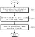
도 12는 도 6의 프로세싱 장치(200)가 제2 베이어 이미지(BI2)를 생성하는 동작을 예시적으로 보여주는 순서도이다. 도 6, 도 11 및 도 12를 참조하면, S211 단계에서, 프로세싱 장치(200)는 포화 정보 및 모션 정보(MI)를 획득할 수 있다. 프로세싱 장치(200)는 포화 검출 모듈(236)을 통해 제1 베이어 이미지(BI1)의 포화 영역을 검출하고, 포화 정보를 획득할 수 있다. 프로세싱 장치(200)는 모션 추정 모듈(220)을 통해 피사체의 모션 정보(MI)를 획득할 수 있다.FIG. 12 is a flowchart illustrating an operation of the
S212 단계에서, 프로세싱 장치(200)는 제1 베이어 이미지(BI1)의 픽셀 값들(BPX)에 대한 가중치를 결정할 수 있다. 프로세싱 장치(200)는 포화 정보 및 모션 정보(MI) 중 적어도 하나에 기초하여 픽셀 값들(BPX)에 대한 가중치를 결정할 수 있다. 예를 들어, 프로세싱 장치(200)는 모션 정보(MI)와 관계없이 포화 영역의 픽셀들(BPX)의 가중치를 0 으로 결정할 수 있다.In step S212, the
S213 단계에서, 프로세싱 장치(200)는 결정된 가중치에 따라 제2 베이어 이미지(BI2)를 생성할 수 있다. 프로세싱 장치(200)는 제2 픽셀 값들(PX2)의 가중치 및 제1 베이어 이미지(BI1)의 픽셀 값들(BPX)의 가중치에 따라 제2 베이어 이미지(BI2)를 생성할 수 있다. 제2 픽셀 값들(PX2)의 가중치는 픽셀 값들(BPX)의 가중치에 의존할 수 있다. 예를 들어, 픽셀 값들(BPX)의 가중치가 감소되면, 제2 픽셀 값들(PX2)의 가중치가 증가될 수 있다. 이에 따라, 프로세싱 장치(200)는 각각의 가중치를 반영하여 제2 베이어 이미지(BI2)를 생성할 수 있다.In step S213, the
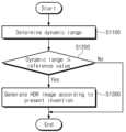
도 13은 도 2의 이미징 시스템(1000)의 예시적인 동작을 보여주는 순서도이다. 도 2 및 도 13을 참조하면, S1100 단계에서, 이미징 시스템(1000)은 피사 환경의 다이내믹 레인지를 판별할 수 있다. 이미징 시스템(1000)은 컨트롤러(300)를 통해 이미지 데이터(IDAT)를 기반으로 다이내믹 레인지를 판별할 수 있다. 예를 들어, 컨트롤러(300)는 이미지 데이터(IDAT)의 통계 정보를 기반으로 다이내믹 레인지를 판별할 수 있다. S1200 단계에서, 이미징 시스템(1000)은 다이내믹 레인지가 기준 값 이하인지 여부를 판별할 수 있다. 예를 들어, 기준 값은 84dB 일 수 있으나, 본 발명이 이에 한정되는 것은 아니다.FIG. 13 is a flowchart showing an example operation of the
다이내믹 레인지가 기준 값 이하인 경우, S1300 단계에서, 이미징 시스템(1000)은 본 발명에 따라 HDR 이미지(HDAT)를 생성할 수 있다. 즉, 도 1 내지 도 12를 참조하여 설명된 바에 따라, HDR 이미지(HDAT)가 생성될 수 있다. 예를 들어, 이미징 시스템(1000)은 픽셀 별 노출 시간을 조절하여 도 4a 내지 도 4c의 노출 패턴을 형성할 수 있다. 이미징 시스템(1000)은 노출 패턴에 따라 하나의 프레임에 대한 이미지 데이터(IDAT)를 획득할 수 있다. 이미징 시스템(1000)은 이미지 데이터(IDAT)를 기반으로 각각의 노출 시간에 대응하는 베이어 이미지들을 순차적으로 생성할 수 있다. 이 경우, 이미징 시스템(1000)은 이전에 생성된 베이어 이미지를 이용하여 다음 베이어 이미지를 생성할 수 있다. 이미징 시스템(1000)은 베이어 이미지들을 기반으로 HDR 이미지(HDAT)를 생성할 수 있다.If the dynamic range is below the reference value, in step S1300, the
다이내믹 레인지가 기준 값보다 큰 경우, 이미징 시스템(1000)은 본 발명과 다른 방법을 이용하여 HDR 이미지(HDAT)를 생성할 수 있다. 예를 들어, 이미징 시스템(1000)은 본 발명과 다른 방식으로 노출 패턴을 형성하거나 이미지 데이터(IDAT)를 처리할 수 있다.If the dynamic range is greater than the reference value, the
상술한 바와 같이, 이미징 시스템(1000)은 피사 환경의 다이내믹 레인지에 따라 HDR 이미지(HDAT)를 생성하기 위한 이미지 데이터(IDAT)의 처리 방식을 선택할 수 있다.As described above, the
도 14는 본 발명의 실시 예에 따른 이미징 시스템이 적용되는 하나의 예시를 나타내는 블록도이다. 도 14를 참조하면, 이미징 시스템(2000)은 이미징 센싱 장치(2100) 및 이미지 신호 프로세서(2200)를 포함할 수 있다. 이미징 센싱 장치(2100)는 이미지 데이터를 획득하고, 획득된 이미지 데이터를 이미지 신호 프로세서(2200)로 제공할 수 있다. 이미지 신호 프로세서(2200)는 HDR 모듈(2210), 노이즈 감소 모듈(2220), 화이트 밸런스 모듈(2230), 디모자이킹 모듈(2240), 감마 보정 모듈(2250), 컬러 변환 모듈(2260)을 포함할 수 있다.Figure 14 is a block diagram showing an example to which an imaging system according to an embodiment of the present invention is applied. Referring to FIG. 14 , the
HDR 모듈(2210)은 이미징 센싱 장치(2100)로부터의 이미지 데이터로부터 HDR 이미지를 생성할 수 있다. HDR 모듈(2210)은 도 1 내지 도 13을 참조하여 설명된 프로세싱 장치(200)의 기능을 포함할 수 있다. 예를 들어, HDR 모듈(2210)은 이미지 데이터를 기반으로 각각의 노출 시간에 대응하는 베이어 이미지들을 순차적으로 생성하고, 베이어 이미지들을 기반으로 HDR 이미지를 생성할 수 있다. 이에 따라, 해상도가 감소되지 않은 고해상도 및 고화질의 HDR 이미지가 생성될 수 있다.The
노이즈 감소 모듈(2220)은 HDR 모듈(2210)로부터의 로우 데이터의 잡음을 제거하도록 구성될 수 있다. 화이트 밸런스 모듈(2230)은 잡음이 제거된 데이터에 대하여, 화이트 밸런스 게인을 조절할 수 있다.
디모자이킹 모듈(2240)은 화이트 밸런스 모듈(2230)의 출력을 풀-컬러 데이터로 변환하도록 구성될 수 있다. 예를 들어, 화이트 밸런스 모듈(2230)의 출력은 베이어 패턴을 가질 수 있다. 디모자이킹 모듈(2240)은 베이어 패턴을 RGB 포맷으로 변환하도록 구성될 수 있다.The
감마 보정 모듈(2250)은 디모자이킹 모듈(2240)로부터의 출력을 기반으로 이미지에 대한 감마 값을 보정하도록 구성될 수 있다. 컬러 변환 모듈(2260)은 감마 보정 모듈(2250)로부터의 출력을 특정 포맷으로 변환하도록 구성될 수 있다. 예를 들어, 감마 보정 모듈(2250)로부터의 출력은 RGB 포맷을 가질 수 있다. 컬러 변환 모듈(2260)은 RGB 포맷을 갖는 감마 보정 모듈(2250)로부터의 출력을 YUV 포맷으로 변환할 수 있다.The
상술된 바와 같이, HDR 모듈(2210)을 통해 생성된 HDR 이미지는 다양한 모듈들을 통해 후처리될 수 있다. 도 14에서는 HDR 모듈(2210)로부터 생성된 HDR 이미지가 노이즈 감소 모듈(2220)로 제공되는 것으로 도시되었으나, 본 발명은 이에 한정되지 않는다. 예를 들어, HDR 모듈(2210)은 노이즈 감소 모듈(2220)을 통해 잡음이 제거된 이미지 데이터로부터 HDR 이미지를 생성할 수 있다.As described above, the HDR image generated through the
도 15는 본 발명의 실시 예들에 따른 이미징 시스템이 적용되는 하나의 예시를 나타내는 블록도이다. 도 15를 참조하면, 이미징 시스템(3000)은 다양한 형태의 전자 장치로 구현될 수 있다. 예를 들어, 이미징 시스템(3000)은 데스크톱 컴퓨터, 랩톱 컴퓨터, 태블릿 컴퓨터, 스마트폰, 웨어러블(wearable) 장치, 전기 자동차 등으로 구현될 수 있다. 이미징 시스템(3000)은 이미지 처리 블록(3100), 통신 블록(3200), 오디오 처리 블록(3300), 디스플레이 장치(3400), 버퍼 메모리(3500), 불휘발성 메모리(3600), 유저 인터페이스(3700) 및 메인 프로세서(3800)를 포함할 수 있다.Figure 15 is a block diagram showing an example to which an imaging system according to embodiments of the present invention is applied. Referring to FIG. 15, the
이미지 처리 블록(3100)은 렌즈(3110)를 통해 광 신호를 수신할 수 있다. 이미지 처리 블록(3100)에 포함되는 이미지 센서(3120) 및 이미지 신호 프로세서(3130)는 수신되는 광 신호에 기초하여 이미지 데이터를 생성할 수 있다. 예를 들어, 이미지 센서(3120)는 도 1 내지 도 13을 참조하여 설명된 이미지 센서(120)의 기능을 포함할 수 있다. 예를 들어, 이미지 센서(3120)는 도 4a 내지 도 4c에서 설명된 노출 패턴에 따라 이미지 데이터를 획득할 수 있다. 이미지 신호 프로세서(3130)는 도 1 내지 도 13을 참조하여 설명된 프로세싱 장치(200)의 기능을 포함할 수 있다. 예를 들어, 이미지 신호 프로세서(3130)는 이미지 데이터를 기반으로 각각의 노출 시간에 대응하는 베이어 이미지들을 순차적으로 생성하고, 베이어 이미지들을 기반으로 HDR 이미지를 생성할 수 있다. 이에 따라, 해상도가 감소되지 않은 고해상도 및 고화질의 HDR 이미지가 생성될 수 있다.The
통신 블록(3200)은 안테나(3210)를 통해 외부 장치/시스템과 신호를 교환할 수 있다. 통신 블록(3200)의 송수신기(3220) 및 MODEM(Modulator/Demodulator, 3230)은 다양한 무선 통신 규약에 따라, 외부 장치/시스템과 교환되는 신호를 처리할 수 있다.The
오디오 처리 블록(3300)은 오디오 신호 프로세서(3310)를 이용하여 소리 정보를 처리할 수 있고, 오디오를 재생하고 출력할 수 있다. 오디오 처리 블록(3300)은 마이크(3320)를 통해 오디오 입력을 수신할 수 있다. 오디오 처리 블록(3300)은 스피커(3330)를 통해, 재생되는 오디오를 출력할 수 있다.The
디스플레이 장치(3400)는 외부 장치(예를 들어, 메인 프로세서(3800))로부터 데이터를 수신하고, 수신된 데이터에 기초하여 디스플레이 패널을 통해 영상을 표시할 수 있다. 예를 들어, 디스플레이 장치(3400)는 이미지 신호 프로세서(3130)로부터 생성된 HDR 이미지를 표시할 수 있다.The
버퍼 메모리(3500)는 이미징 시스템(3000)의 동작에 이용되는 데이터를 저장할 수 있다. 예시적으로, 버퍼 메모리(3500)는 메인 프로세서(3800)에 의해 처리된 또는 처리될 데이터를 일시적으로 저장할 수 있다. 예시적으로, 버퍼 메모리(3500)는 SRAM(Static Random Access Memory), DRAM(Dynamic RAM), SDRAM(Synchronous DRAM) 등과 같은 휘발성 메모리, 및/또는 PRAM(Phase-change RAM), MRAM(Magneto-resistive RAM), ReRAM(Resistive RAM), FRAM(Ferro-electric RAM) 등과 같은 불휘발성 메모리를 포함할 수 있다.The
불휘발성 메모리(3600)는 전력 공급과 무관하게 데이터를 저장할 수 있다. 예시적으로, 불휘발성 메모리(3600)는 플래시 메모리, PRAM, MRAM, ReRAM, FRAM 등과 같은 다양한 불휘발성 메모리 중 적어도 하나를 포함할 수 있다. 예시적으로, 불휘발성 메모리(3600)는 SD(Secure Digital) 카드와 같은 착탈식 메모리, 및/또는 eMMC(Embedded Multimedia Card)와 같은 내장(Embedded) 메모리를 포함할 수 있다.The
유저 인터페이스(3700)는 사용자와 이미징 시스템(3000) 사이의 통신을 중재할 수 있다. 예시적으로, 유저 인터페이스(3700)는 키패드, 버튼, 터치 스크린, 터치 패드, 자이로스코프 센서, 진동 센서, 가속 센서 등과 같은 입력 인터페이스를 포함할 수 있다. 예시적으로, 유저 인터페이스(3700)는 모터, LED 램프 등과 같은 출력 인터페이스를 포함할 수 있다.
메인 프로세서(3800)는 이미징 시스템(3000)의 구성 요소들의 전반적인 동작들을 제어할 수 있다. 메인 프로세서(3800)는 이미징 시스템(3000)을 동작시키기 위해 다양한 연산을 처리할 수 있다. 예시적으로, 메인 프로세서(3800)는 범용(General-purpose) 프로세서, 전용(Special-purpose) 프로세서, 애플리케이션(Application) 프로세서, 마이크로프로세서 등과 같이, 하나 이상의 프로세서 코어를 포함하는 연산 처리 장치/회로로 구현될 수 있다. 예를 들어, 메인 프로세서(3800)는 도 1 내지 도 13을 참조하여 설명된 컨트롤러(300)의 기능을 포함할 수 있다.The
상술된 내용은 본 발명을 실시하기 위한 구체적인 실시 예들이다. 본 발명은 상술된 실시 예들뿐만 아니라, 단순하게 설계 변경되거나 용이하게 변경할 수 있는 실시 예들 또한 포함할 것이다. 또한, 본 발명은 실시 예들을 이용하여 용이하게 변형하여 실시할 수 있는 기술들도 포함될 것이다. 따라서, 본 발명의 범위는 상술된 실시 예들에 국한되어 정해져서는 안되며 후술하는 특허청구범위뿐만 아니라 이 발명의 특허청구범위와 균등한 것들에 의해 정해져야 할 것이다.The above-described details are specific embodiments for carrying out the present invention. The present invention will include not only the above-described embodiments, but also embodiments that can be simply changed or easily changed in design. In addition, the present invention will also include technologies that can be easily modified and implemented using the embodiments. Therefore, the scope of the present invention should not be limited to the above-described embodiments, but should be determined by the claims and equivalents of the present invention as well as the claims described later.
100: 이미지 센싱 장치 110: 렌즈
120: 이미지 센서 121: 픽셀 어레이
122: 구동 회로 123: 출력 회로
200: 프로세싱 장치 210: 패턴 분리 모듈
220: 모션 추정 모듈 230: 베이어 이미지 생성 블록
231: 제1 베이어 이미지 생성 모듈 232: 제2 베이어 이미지 생성 모듈
240: 이미지 재구성 모듈 1000: 이미징 시스템100: image sensing device 110: lens
120: image sensor 121: pixel array
122: driving circuit 123: output circuit
200: processing device 210: pattern separation module
220: Motion estimation module 230: Bayer image generation block
231: first Bayer image generation module 232: second Bayer image generation module
240: Image reconstruction module 1000: Imaging system
Claims (20)
Translated fromKorean제1 노출 시간에 기반하여 상기 제1 픽셀들을 제어하고, 제2 노출 시간에 기반하여 상기 제2 픽셀들을 제어하는 구동 회로;
상기 픽셀 어레이로부터 상기 제1 픽셀들의 제1 픽셀 값들 및 상기 제2 픽셀들의 제2 픽셀 값들을 출력하는 출력 회로; 및
상기 제1 픽셀 값들을 이용한 보간에 기반하여 생성된 제3 픽셀들을 포함하는 제1 베이어 이미지, 및 상기 제2 픽셀 값들과 상기 제3 픽셀들의 제3 픽셀 값들에 기반하여 생성된 제2 베이어 이미지에 기반하여 HDR(high dynamic range) 이미지를 생성하는 프로세싱 회로를 포함하되,
상기 제1 픽셀들의 수는 상기 제2 픽셀들의 수보다 크고,
상기 프로세싱 회로는:
상기 픽셀 어레이에 대한 노출 시간 정보에 기반하여, 상기 제1 픽셀 값들 및 상기 제2 픽셀 값들을 각각 분리하여 분리된 제1 픽셀 값들 및 분리된 제2 픽셀 값들을 더 생성하고,
상기 분리된 제1 픽셀 값들을 이용한 보간에 기반하여 상기 제1 베이어 이미지를 더 생성하고,
상기 분리된 제2 픽셀 값들과 상기 제3 픽셀 값들에 기반하여 상기 제2 베이어 이미지를 더 생성하고,
상기 제1 픽셀 값들 및 상기 제2 픽셀 값들에 기반하여 피사체의 모션 정보를 더 추정하고, 그리고
상기 추정된 모션 정보에 기반하여 상기 제2 베이어 이미지를 생성하기 위해 상기 제3 픽셀 값들의 가중치를 더 결정하는 이미징 시스템.a pixel array including a plurality of first pixels and a plurality of second pixels different from the plurality of first pixels;
a driving circuit that controls the first pixels based on a first exposure time and the second pixels based on a second exposure time;
an output circuit that outputs first pixel values of the first pixels and second pixel values of the second pixels from the pixel array; and
A first Bayer image including third pixels generated based on interpolation using the first pixel values, and a second Bayer image generated based on the second pixel values and third pixel values of the third pixels. It includes a processing circuit that generates a high dynamic range (HDR) image based on
The number of first pixels is greater than the number of second pixels,
The processing circuitry is:
Based on exposure time information for the pixel array, separate the first pixel values and the second pixel values to further generate separate first pixel values and separate second pixel values,
Further generating the first Bayer image based on interpolation using the separated first pixel values,
further generating the second Bayer image based on the separated second pixel values and the third pixel values,
further estimate motion information of the subject based on the first pixel values and the second pixel values, and
and further determine weights of the third pixel values to generate the second Bayer image based on the estimated motion information.
상기 프로세싱 회로는 상기 분리된 제1 픽셀 값들에 기반하여 픽셀 값들을 보간하여 보간 이미지를 생성하고, 상기 보간 이미지를 베이어 패턴으로 변환하는 것에 기반하여 상기 제1 베이어 이미지를 생성하는 이미징 시스템.According to claim 1,
The processing circuit generates an interpolated image by interpolating pixel values based on the separated first pixel values, and generates the first Bayer image based on converting the interpolated image into a Bayer pattern.
상기 프로세싱 회로는 상기 제1 베이어 이미지에 하나 이상의 포화된 픽셀들을 포함하는 포화 영역이 존재하는지 여부에 응답하여, 상기 제3 픽셀 값들 중 상기 하나 이상의 포화된 픽셀들의 픽셀 값들을 제외한 나머지 픽셀 값들에 기반하여 상기 제2 베이어 이미지의 픽셀 값들을 더 생성하는 이미징 시스템.According to claim 1,
The processing circuit is responsive to whether a saturated region including one or more saturated pixels exists in the first Bayer image, based on pixel values remaining among the third pixel values excluding the pixel values of the one or more saturated pixels. An imaging system that further generates pixel values of the second Bayer image.
상기 제1 픽셀들의 노출 시간을 상기 제1 노출 시간으로 결정하고, 상기 제2 픽셀들의 노출 시간을 상기 제2 노출 시간으로 결정하는 컨트롤러를 더 포함하는 이미징 시스템.According to claim 1,
The imaging system further includes a controller that determines the exposure time of the first pixels as the first exposure time, and determines the exposure time of the second pixels as the second exposure time.
상기 컨트롤러는 상기 출력 회로로부터 출력되는 픽셀 값들에 기반하여 상기 제1 픽셀들의 상기 노출 시간 및 상기 제2 픽셀들의 상기 노출 시간을 결정하는 이미징 시스템.According to claim 4,
The controller determines the exposure time of the first pixels and the exposure time of the second pixels based on pixel values output from the output circuit.
상기 픽셀 어레이 상부에 위치한 복수의 컬러 필터들을 포함하는 컬러 필터 배열(CFA; color filter array)을 더 포함하고,
상기 복수의 컬러 필터들 중 적어도 인접한 두 개의 컬러 필터들은 레드 컬러, 그린 컬러, 또는 블루 컬러 중 동일한 컬러를 갖는 빛을 선택적으로 전송하는 이미징 시스템.According to claim 1,
Further comprising a color filter array (CFA) including a plurality of color filters located on top of the pixel array,
An imaging system wherein at least two adjacent color filters among the plurality of color filters selectively transmit light having the same color among red, green, or blue.
상기 제1 픽셀 값들 및 상기 제2 픽셀 값들은 하나의 프레임으로부터 획득되는 이미징 시스템.According to claim 1,
The imaging system wherein the first pixel values and the second pixel values are obtained from one frame.
상기 제1 베이어 이미지의 해상도와 상기 제2 베이어 이미지의 해상도는 상기 픽셀 어레이의 픽셀들의 전체 수와 동일한 이미징 시스템.According to claim 1,
An imaging system wherein the resolution of the first Bayer image and the resolution of the second Bayer image are equal to the total number of pixels of the pixel array.
상기 제1 노출 시간은 상기 제2 노출 시간보다 긴 이미징 시스템.According to claim 1,
The first exposure time is longer than the second exposure time.
제1 노출 시간에 기반하여 상기 제1 내지 상기 제4 픽셀들의 제1 부분을 제어하고, 제2 노출 시간에 기반하여 상기 제1 내지 상기 제4 픽셀들의 제2 부분을 제어하는 구동 회로;
상기 제1 노출 시간에 기반하여 상기 제1 내지 상기 제4 픽셀들의 상기 제1 부분의 제1 픽셀 값들, 및 상기 제2 노출 시간에 기반하여 상기 제1 내지 상기 제4 픽셀들의 상기 제2 부분의 제2 픽셀 값들을 출력하는 출력 회로; 및
상기 제1 픽셀 값들에 기반하여 제1 베이어 이미지를 생성하고, 상기 제2 픽셀 값들과 상기 제1 베이어 이미지에 기반하여 제2 베이어 이미지를 생성하고, 상기 제1 베이어 이미지와 상기 제2 베이어 이미지에 기반하여 제3 베이어 이미지를 생성하고, 그리고 상기 제1 픽셀 값들 및 상기 제2 픽셀 값들에 기반하여 피사체의 모션 정보를 추정하고, 상기 모션 정보에 기반하여 상기 제1 베이어 이미지의 픽셀 값들의 제1 가중치 및 상기 제2 베이어 이미지의 픽셀 값들의 제2 가중치를 결정하는 프로세싱 회로를 포함하되,
상기 제1 노출 시간은 상기 제2 노출 시간보다 긴 이미징 시스템.A first sub-block including first pixels adjacent to each other and corresponding to a first color filter, a second sub-block including second pixels adjacent to each other and corresponding to a second color filter, and third pixels adjacent to each other a pixel array including a third sub-block corresponding to a third color filter, and a fourth sub-block including fourth pixels adjacent to each other and corresponding to a fourth color filter;
a driving circuit that controls a first portion of the first to fourth pixels based on a first exposure time and controls a second portion of the first to fourth pixels based on a second exposure time;
The first pixel values of the first portion of the first to fourth pixels based on the first exposure time, and the second portion of the first to fourth pixels based on the second exposure time. an output circuit that outputs second pixel values; and
Generating a first Bayer image based on the first pixel values, generating a second Bayer image based on the second pixel values and the first Bayer image, and combining the first Bayer image and the second Bayer image generate a third Bayer image based on the first pixel values, and estimate motion information of the subject based on the first pixel values and the second pixel values, and generate a first pixel value of the first Bayer image based on the motion information. A processing circuit that determines a weight and a second weight of pixel values of the second Bayer image,
The first exposure time is longer than the second exposure time.
Priority Applications (4)
| Application Number | Priority Date | Filing Date | Title |
|---|---|---|---|
| KR1020190006857AKR102648747B1 (en) | 2019-01-18 | 2019-01-18 | Imaging system for generating hdr image and operating method thereof |
| US16/547,786US11082625B2 (en) | 2019-01-18 | 2019-08-22 | Imaging systems for generating HDR images and operating methods thereof |
| CN201910977457.0ACN111464754B (en) | 2019-01-18 | 2019-10-14 | Imaging system for generating HDR images and method of operation thereof |
| US17/362,380US11622081B2 (en) | 2019-01-18 | 2021-06-29 | Imaging systems for generating HDR images and operating methods thereof |
Applications Claiming Priority (1)
| Application Number | Priority Date | Filing Date | Title |
|---|---|---|---|
| KR1020190006857AKR102648747B1 (en) | 2019-01-18 | 2019-01-18 | Imaging system for generating hdr image and operating method thereof |
Publications (2)
| Publication Number | Publication Date |
|---|---|
| KR20200090291A KR20200090291A (en) | 2020-07-29 |
| KR102648747B1true KR102648747B1 (en) | 2024-03-20 |
Family
ID=71609276
Family Applications (1)
| Application Number | Title | Priority Date | Filing Date |
|---|---|---|---|
| KR1020190006857AActiveKR102648747B1 (en) | 2019-01-18 | 2019-01-18 | Imaging system for generating hdr image and operating method thereof |
Country Status (3)
| Country | Link |
|---|---|
| US (2) | US11082625B2 (en) |
| KR (1) | KR102648747B1 (en) |
| CN (1) | CN111464754B (en) |
Families Citing this family (7)
| Publication number | Priority date | Publication date | Assignee | Title |
|---|---|---|---|---|
| US11064134B2 (en)* | 2019-06-05 | 2021-07-13 | Omnivision Technologies, Inc. | High-dynamic range image sensor and image-capture method |
| US11102422B2 (en) | 2019-06-05 | 2021-08-24 | Omnivision Technologies, Inc. | High-dynamic range image sensor and image-capture method |
| CN111479072B (en)* | 2020-04-14 | 2021-12-17 | 深圳市道通智能航空技术股份有限公司 | High dynamic range image synthesis method and device, image processing chip and aerial camera |
| US11843868B2 (en) | 2021-07-13 | 2023-12-12 | SK Hynix Inc. | Electronic apparatus based on multiple exposure image and operating method thereof |
| CN113676636B (en)* | 2021-08-16 | 2023-05-05 | Oppo广东移动通信有限公司 | Method and device for generating high dynamic range image, electronic equipment and storage medium |
| KR20230055626A (en)* | 2021-10-19 | 2023-04-26 | 에스케이하이닉스 주식회사 | Imaging Device |
| WO2024123095A1 (en)* | 2022-12-07 | 2024-06-13 | 주식회사 엘엑스세미콘 | Image sensor |
Family Cites Families (44)
| Publication number | Priority date | Publication date | Assignee | Title |
|---|---|---|---|---|
| US6864916B1 (en) | 1999-06-04 | 2005-03-08 | The Trustees Of Columbia University In The City Of New York | Apparatus and method for high dynamic range imaging using spatially varying exposures |
| US7084905B1 (en) | 2000-02-23 | 2006-08-01 | The Trustees Of Columbia University In The City Of New York | Method and apparatus for obtaining high dynamic range images |
| JP4131192B2 (en) | 2003-04-25 | 2008-08-13 | コニカミノルタオプト株式会社 | Imaging apparatus, image processing apparatus, and image recording apparatus |
| US7825969B2 (en) | 2006-12-15 | 2010-11-02 | Nokia Corporation | Image stabilization using multi-exposure pattern |
| US7548689B2 (en)* | 2007-04-13 | 2009-06-16 | Hewlett-Packard Development Company, L.P. | Image processing method |
| KR100835894B1 (en) | 2007-06-18 | 2008-06-09 | (주)실리콘화일 | Pixel array and image sensor with wide dynamic range and excellent color reproduction and resolution |
| US8022994B2 (en) | 2007-08-31 | 2011-09-20 | Omnivision Technologies, Inc. | Image sensor with high dynamic range in down-sampling mode |
| US7940311B2 (en)* | 2007-10-03 | 2011-05-10 | Nokia Corporation | Multi-exposure pattern for enhancing dynamic range of images |
| US7777804B2 (en) | 2007-10-26 | 2010-08-17 | Omnivision Technologies, Inc. | High dynamic range sensor with reduced line memory for color interpolation |
| TWI422020B (en) | 2008-12-08 | 2014-01-01 | Sony Corp | Solid-state imaging device |
| JP4877359B2 (en)* | 2009-02-10 | 2012-02-15 | ソニー株式会社 | Solid-state imaging device and imaging device |
| KR101643319B1 (en)* | 2010-01-11 | 2016-07-27 | 삼성전자주식회사 | Apparatus and Method for obtaining high dynamic range image |
| JP5411786B2 (en) | 2010-04-08 | 2014-02-12 | 日本放送協会 | Image capturing apparatus and image integration program |
| US8994843B2 (en)* | 2010-09-01 | 2015-03-31 | Qualcomm Incorporated | High dynamic range image sensor |
| EP2442556A1 (en) | 2010-10-15 | 2012-04-18 | ST-Ericsson SA | Apparatus and method for capturing images with high dynamic range |
| JP5655626B2 (en)* | 2011-02-24 | 2015-01-21 | ソニー株式会社 | Image processing apparatus, image processing method, and program |
| JP2012234393A (en)* | 2011-05-02 | 2012-11-29 | Sony Corp | Image processing device, image processing method, and program |
| KR101699919B1 (en) | 2011-07-28 | 2017-01-26 | 삼성전자주식회사 | High dynamic range image creation apparatus of removaling ghost blur by using multi exposure fusion and method of the same |
| US9129414B2 (en) | 2011-10-14 | 2015-09-08 | Morpho, Inc. | Image compositing apparatus, image compositing method, image compositing program, and recording medium |
| KR101225482B1 (en) | 2012-02-15 | 2013-01-23 | 인텔 코오퍼레이션 | Digital image processing method, apparatus, and computer-readable recording medium |
| US9040892B2 (en) | 2012-07-27 | 2015-05-26 | Apple Inc. | High dynamic range image sensor having symmetric interleaved long and short exposure pixels |
| JP6335423B2 (en) | 2012-08-31 | 2018-05-30 | キヤノン株式会社 | Information processing apparatus and information processing method |
| US9338372B2 (en) | 2012-09-19 | 2016-05-10 | Semiconductor Components Industries, Llc | Column-based high dynamic range imaging systems |
| JP2014086889A (en)* | 2012-10-24 | 2014-05-12 | Toshiba Corp | Solid-state imaging apparatus |
| US9071765B2 (en)* | 2012-12-28 | 2015-06-30 | Nvidia Corporation | System, method, and computer program product implementing an image processing pipeline for high-dynamic range images |
| KR101488074B1 (en)* | 2013-02-04 | 2015-01-29 | 주식회사 동부하이텍 | Image sensorand method for generating binning image using the same |
| US9413992B2 (en)* | 2013-05-20 | 2016-08-09 | Omnivision Technologies, Inc. | High dynamic range image sensor with full resolution recovery |
| US10142563B2 (en)* | 2013-07-04 | 2018-11-27 | Nikon Corporation | Electronic apparatus, method for controlling electronic apparatus, and control program |
| EP3079353B1 (en)* | 2013-12-04 | 2021-03-03 | Sony Semiconductor Solutions Corporation | Image processing device, image processing method, electronic apparatus, and program |
| KR101477505B1 (en) | 2013-12-23 | 2015-01-07 | 이동현 | Forming Method of High Dynamic Range Image |
| KR102149187B1 (en)* | 2014-02-21 | 2020-08-28 | 삼성전자주식회사 | Electronic device and control method of the same |
| JP6417809B2 (en)* | 2014-03-05 | 2018-11-07 | ソニー株式会社 | Imaging device |
| JP6434963B2 (en)* | 2014-04-22 | 2018-12-05 | ソニーセミコンダクタソリューションズ株式会社 | Image processing apparatus, image processing method, electronic device, and program |
| KR20150128168A (en) | 2014-05-08 | 2015-11-18 | 삼성전자주식회사 | White balancing device and white balancing method thereof |
| JP2015231118A (en)* | 2014-06-04 | 2015-12-21 | キヤノン株式会社 | Image composition apparatus, image composition system, and image composition method |
| WO2015196456A1 (en)* | 2014-06-27 | 2015-12-30 | 深圳市大疆创新科技有限公司 | High dynamic range video record method and apparatus based on bayer color filter array |
| KR102273656B1 (en)* | 2014-11-24 | 2021-07-05 | 삼성전자주식회사 | Noise level control device of wide dynanamic range image, and image processing system including the same |
| US9282256B1 (en) | 2014-12-22 | 2016-03-08 | Omnivision Technologies, Inc. | System and method for HDR imaging |
| US9467633B2 (en) | 2015-02-27 | 2016-10-11 | Semiconductor Components Industries, Llc | High dynamic range imaging systems having differential photodiode exposures |
| KR102277178B1 (en) | 2015-03-09 | 2021-07-14 | 삼성전자 주식회사 | Electronic Device Including The Camera Module And Method For Processing Image Of the Same |
| CN104639845B (en)* | 2015-03-17 | 2017-12-26 | 上海兆芯集成电路有限公司 | High dynamic range images production method and the device using this method |
| KR102356706B1 (en)* | 2015-07-07 | 2022-01-27 | 삼성전자주식회사 | Image Sensor Having Wide Dynamic Range, Pixel Circuit Of Image Sensor and Operating Method Thereof |
| US10313600B2 (en) | 2015-10-13 | 2019-06-04 | Canon Kabushiki Kaisha | Imaging device capable of simultaneously capturing of a motion image and a static image and imaging method |
| KR102354991B1 (en)* | 2017-05-24 | 2022-01-24 | 삼성전자주식회사 | Pixel circuit and image sensor including thereof |
- 2019
- 2019-01-18KRKR1020190006857Apatent/KR102648747B1/enactiveActive
- 2019-08-22USUS16/547,786patent/US11082625B2/enactiveActive
- 2019-10-14CNCN201910977457.0Apatent/CN111464754B/enactiveActive
- 2021
- 2021-06-29USUS17/362,380patent/US11622081B2/enactiveActive
Also Published As
| Publication number | Publication date |
|---|---|
| KR20200090291A (en) | 2020-07-29 |
| US11082625B2 (en) | 2021-08-03 |
| US20200236273A1 (en) | 2020-07-23 |
| US20210329160A1 (en) | 2021-10-21 |
| CN111464754A (en) | 2020-07-28 |
| CN111464754B (en) | 2021-11-16 |
| US11622081B2 (en) | 2023-04-04 |
Similar Documents
| Publication | Publication Date | Title |
|---|---|---|
| KR102648747B1 (en) | Imaging system for generating hdr image and operating method thereof | |
| US9538092B2 (en) | Methods and apparatus to generate wide dynamic range images | |
| US9756266B2 (en) | Sensor data rescaler for image signal processing | |
| US9787922B2 (en) | Pixel defect preprocessing in an image signal processor | |
| CN105430359B (en) | Imaging method, imaging sensor, imaging device and electronic device | |
| US12212856B2 (en) | Imaging system for generating high dynamic range image | |
| TW200915861A (en) | Method and apparatus for improving low-light performance for small pixel image sensors | |
| JP2012175600A (en) | Imaging apparatus, imaging apparatus control method, and program | |
| KR20190005252A (en) | Parallel Computer Vision and Image Scaling Architecture | |
| CN107615751B (en) | Solid-state imaging elements and electronic devices | |
| US9462189B2 (en) | Piecewise perspective transform engine | |
| CN105611257B (en) | imaging method, image sensor, imaging device and electronic device | |
| JP2017188760A (en) | Image processing apparatus, image processing method, computer program, and electronic apparatus | |
| US10375368B2 (en) | Image data conversion | |
| US8976276B2 (en) | Image processing apparatus, image capturing apparatus, and image processing method | |
| US10009544B2 (en) | Image capturing apparatus, control method of the same and image sensor | |
| CN108989713A (en) | Image processing method, electronic device and non-transitory computer readable recording medium | |
| US11240442B2 (en) | Signal processing apparatus and signal processing method | |
| KR20130133370A (en) | Method and apparatus for image processing | |
| JP4614925B2 (en) | Pixel information reading method and imaging apparatus | |
| US12260511B2 (en) | Front-end scaler circuit for processing demosaiced image data | |
| JP2008035279A (en) | Pixel information reading method and imaging apparatus | |
| JP2014207503A5 (en) | ||
| KR102370881B1 (en) | An electronic device and a method capable of compressing an image based on a property of an image data | |
| JP7094454B2 (en) | Image pickup device, image pickup element, operation method of image pickup device, operation method of image pickup device, and program |
Legal Events
| Date | Code | Title | Description |
|---|---|---|---|
| PA0109 | Patent application | Patent event code:PA01091R01D Comment text:Patent Application Patent event date:20190118 | |
| PG1501 | Laying open of application | ||
| A201 | Request for examination | ||
| PA0201 | Request for examination | Patent event code:PA02012R01D Patent event date:20220117 Comment text:Request for Examination of Application Patent event code:PA02011R01I Patent event date:20190118 Comment text:Patent Application | |
| E902 | Notification of reason for refusal | ||
| PE0902 | Notice of grounds for rejection | Comment text:Notification of reason for refusal Patent event date:20230626 Patent event code:PE09021S01D | |
| E701 | Decision to grant or registration of patent right | ||
| PE0701 | Decision of registration | Patent event code:PE07011S01D Comment text:Decision to Grant Registration Patent event date:20231214 | |
| GRNT | Written decision to grant | ||
| PR0701 | Registration of establishment | Comment text:Registration of Establishment Patent event date:20240313 Patent event code:PR07011E01D | |
| PR1002 | Payment of registration fee | Payment date:20240314 End annual number:3 Start annual number:1 | |
| PG1601 | Publication of registration |