KR102648319B1 - Apparatus for battery balancing and battery pack including the same - Google Patents
Apparatus for battery balancing and battery pack including the sameDownload PDFInfo
- Publication number
- KR102648319B1 KR102648319B1KR1020180101580AKR20180101580AKR102648319B1KR 102648319 B1KR102648319 B1KR 102648319B1KR 1020180101580 AKR1020180101580 AKR 1020180101580AKR 20180101580 AKR20180101580 AKR 20180101580AKR 102648319 B1KR102648319 B1KR 102648319B1
- Authority
- KR
- South Korea
- Prior art keywords
- battery
- count
- voltage
- selection signal
- signal
- Prior art date
- Legal status (The legal status is an assumption and is not a legal conclusion. Google has not performed a legal analysis and makes no representation as to the accuracy of the status listed.)
- Active
Links
- 230000004044responseEffects0.000claimsabstractdescription88
- 230000007423decreaseEffects0.000claimsdescription16
- 230000007704transitionEffects0.000description12
- 230000000875corresponding effectEffects0.000description7
- 238000007599dischargingMethods0.000description5
- PXHVJJICTQNCMI-UHFFFAOYSA-NNickelChemical compound[Ni]PXHVJJICTQNCMI-UHFFFAOYSA-N0.000description4
- 238000012986modificationMethods0.000description3
- 230000004048modificationEffects0.000description3
- WHXSMMKQMYFTQS-UHFFFAOYSA-NLithiumChemical compound[Li]WHXSMMKQMYFTQS-UHFFFAOYSA-N0.000description2
- 238000010586diagramMethods0.000description2
- 230000000694effectsEffects0.000description2
- 230000006870functionEffects0.000description2
- 229910052744lithiumInorganic materials0.000description2
- 229910001416lithium ionInorganic materials0.000description2
- 238000000034methodMethods0.000description2
- 229910052759nickelInorganic materials0.000description2
- 230000008569processEffects0.000description2
- UFHFLCQGNIYNRP-UHFFFAOYSA-NHydrogenChemical compound[H][H]UFHFLCQGNIYNRP-UHFFFAOYSA-N0.000description1
- 239000002253acidSubstances0.000description1
- OJIJEKBXJYRIBZ-UHFFFAOYSA-Ncadmium nickelChemical compound[Ni].[Cd]OJIJEKBXJYRIBZ-UHFFFAOYSA-N0.000description1
- 230000002596correlated effectEffects0.000description1
- 230000006866deteriorationEffects0.000description1
- 238000004146energy storageMethods0.000description1
- 238000005516engineering processMethods0.000description1
- 230000005669field effectEffects0.000description1
- 229910052739hydrogenInorganic materials0.000description1
- 239000001257hydrogenSubstances0.000description1
- 230000003446memory effectEffects0.000description1
- QELJHCBNGDEXLD-UHFFFAOYSA-Nnickel zincChemical compound[Ni].[Zn]QELJHCBNGDEXLD-UHFFFAOYSA-N0.000description1
- 230000001151other effectEffects0.000description1
- 239000004065semiconductorSubstances0.000description1
- 238000006467substitution reactionMethods0.000description1
- 238000011144upstream manufacturingMethods0.000description1
Images


Classifications
- H—ELECTRICITY
- H02—GENERATION; CONVERSION OR DISTRIBUTION OF ELECTRIC POWER
- H02J—CIRCUIT ARRANGEMENTS OR SYSTEMS FOR SUPPLYING OR DISTRIBUTING ELECTRIC POWER; SYSTEMS FOR STORING ELECTRIC ENERGY
- H02J7/00—Circuit arrangements for charging or depolarising batteries or for supplying loads from batteries
- H02J7/0013—Circuit arrangements for charging or depolarising batteries or for supplying loads from batteries acting upon several batteries simultaneously or sequentially
- H02J7/0014—Circuits for equalisation of charge between batteries
- H02J7/0019—Circuits for equalisation of charge between batteries using switched or multiplexed charge circuits
- B—PERFORMING OPERATIONS; TRANSPORTING
- B60—VEHICLES IN GENERAL
- B60L—PROPULSION OF ELECTRICALLY-PROPELLED VEHICLES; SUPPLYING ELECTRIC POWER FOR AUXILIARY EQUIPMENT OF ELECTRICALLY-PROPELLED VEHICLES; ELECTRODYNAMIC BRAKE SYSTEMS FOR VEHICLES IN GENERAL; MAGNETIC SUSPENSION OR LEVITATION FOR VEHICLES; MONITORING OPERATING VARIABLES OF ELECTRICALLY-PROPELLED VEHICLES; ELECTRIC SAFETY DEVICES FOR ELECTRICALLY-PROPELLED VEHICLES
- B60L58/00—Methods or circuit arrangements for monitoring or controlling batteries or fuel cells, specially adapted for electric vehicles
- B60L58/10—Methods or circuit arrangements for monitoring or controlling batteries or fuel cells, specially adapted for electric vehicles for monitoring or controlling batteries
- B60L58/18—Methods or circuit arrangements for monitoring or controlling batteries or fuel cells, specially adapted for electric vehicles for monitoring or controlling batteries of two or more battery modules
- B60L58/22—Balancing the charge of battery modules
- H—ELECTRICITY
- H01—ELECTRIC ELEMENTS
- H01M—PROCESSES OR MEANS, e.g. BATTERIES, FOR THE DIRECT CONVERSION OF CHEMICAL ENERGY INTO ELECTRICAL ENERGY
- H01M10/00—Secondary cells; Manufacture thereof
- H01M10/42—Methods or arrangements for servicing or maintenance of secondary cells or secondary half-cells
- H01M10/425—Structural combination with electronic components, e.g. electronic circuits integrated to the outside of the casing
- H01M2010/4271—Battery management systems including electronic circuits, e.g. control of current or voltage to keep battery in healthy state, cell balancing
- Y—GENERAL TAGGING OF NEW TECHNOLOGICAL DEVELOPMENTS; GENERAL TAGGING OF CROSS-SECTIONAL TECHNOLOGIES SPANNING OVER SEVERAL SECTIONS OF THE IPC; TECHNICAL SUBJECTS COVERED BY FORMER USPC CROSS-REFERENCE ART COLLECTIONS [XRACs] AND DIGESTS
- Y02—TECHNOLOGIES OR APPLICATIONS FOR MITIGATION OR ADAPTATION AGAINST CLIMATE CHANGE
- Y02E—REDUCTION OF GREENHOUSE GAS [GHG] EMISSIONS, RELATED TO ENERGY GENERATION, TRANSMISSION OR DISTRIBUTION
- Y02E60/00—Enabling technologies; Technologies with a potential or indirect contribution to GHG emissions mitigation
- Y02E60/10—Energy storage using batteries
- Y—GENERAL TAGGING OF NEW TECHNOLOGICAL DEVELOPMENTS; GENERAL TAGGING OF CROSS-SECTIONAL TECHNOLOGIES SPANNING OVER SEVERAL SECTIONS OF THE IPC; TECHNICAL SUBJECTS COVERED BY FORMER USPC CROSS-REFERENCE ART COLLECTIONS [XRACs] AND DIGESTS
- Y02—TECHNOLOGIES OR APPLICATIONS FOR MITIGATION OR ADAPTATION AGAINST CLIMATE CHANGE
- Y02T—CLIMATE CHANGE MITIGATION TECHNOLOGIES RELATED TO TRANSPORTATION
- Y02T10/00—Road transport of goods or passengers
- Y02T10/60—Other road transportation technologies with climate change mitigation effect
- Y02T10/70—Energy storage systems for electromobility, e.g. batteries
Landscapes
- Engineering & Computer Science (AREA)
- Power Engineering (AREA)
- Life Sciences & Earth Sciences (AREA)
- Sustainable Development (AREA)
- Sustainable Energy (AREA)
- Transportation (AREA)
- Mechanical Engineering (AREA)
- Charge And Discharge Circuits For Batteries Or The Like (AREA)
- Secondary Cells (AREA)
Abstract
Translated fromKoreanDescription
Translated fromKorean본 발명은 복수의 배터리를 밸런싱하기 위한 장치 및 상기 장치를 포함하는 배터리팩에 관한 것이다.The present invention relates to a device for balancing a plurality of batteries and a battery pack including the device.
최근, 노트북, 비디오 카메라, 휴대용 전화기 등과 같은 휴대용 전자 제품의 수요가 급격하게 증대되고, 전기 자동차, 에너지 저장용 축전지, 로봇, 위성 등의 개발이 본격화됨에 따라, 반복적인 충방전이 가능한 고성능 이차 전지에 대한 연구가 활발히 진행되고 있다.Recently, as the demand for portable electronic products such as laptops, video cameras, and portable phones has rapidly increased, and as the development of electric vehicles, energy storage batteries, robots, and satellites has begun, high-performance secondary batteries capable of repeated charging and discharging have been developed. Research is actively underway.
현재 상용화된 이차 전지로는 니켈 카드뮴 전지, 니켈 수소 전지, 니켈 아연 전지, 리튬 이차 전지 등이 있는데, 이 중에서 리튬 이차 전지는 니켈 계열의 이차 전지에 비해 메모리 효과가 거의 일어나지 않아 충방전이 자유롭고, 자가 방전율이 매우 낮으며 에너지 밀도가 높은 장점으로 각광을 받고 있다.Currently commercialized secondary batteries include nickel cadmium batteries, nickel hydrogen batteries, nickel zinc batteries, and lithium secondary batteries. Among these, lithium secondary batteries have little memory effect compared to nickel-based secondary batteries, so they can be freely charged and discharged. It is receiving attention for its extremely low self-discharge rate and high energy density.
최근 전기 자동차 등에서 고출력이 요구됨에 따라, 이에 탑재되는 배터리팩에는 서로 직렬 연결된 복수의 배터리가 포함되는 것이 일반적이다. 그런데, 배터리들은 완벽하게 동일한 특성을 가질 수는 없기 때문에, 배터리팩의 충방전이 반복될수록 배터리들 간의 충전 상태(SOC: State Of Charge)에 불균형이 발생할 수 밖에 없다. 이러한 불균형을 억제하지 않고 계속적으로 배터리팩의 충방전을 반복할 경우, 배터리팩의 가용 용량이 감소할 뿐만 아니라, 이에 포함된 배터리들의 퇴화가 가속화된다.As high output is recently required in electric vehicles, etc., battery packs mounted thereon generally include a plurality of batteries connected in series. However, since batteries cannot have completely identical characteristics, as charging and discharging of the battery pack is repeated, an imbalance in the state of charge (SOC) between the batteries is inevitable. If the battery pack is continuously charged and discharged repeatedly without suppressing this imbalance, not only does the usable capacity of the battery pack decrease, but the deterioration of the batteries included therein is accelerated.
위와 같은 문제를 해결하기 위해 배경 기술로서 특허문헌 1이 있다. 특허문헌 1에서는, 복수의 배터리 중에서 상대적으로 높은 충전 상태를 가지는 것을 강제적으로 방전시킴으로써 배터리 셀들 사이의 충전 상태를 균일화한다. 그러나, 특허문헌 1의 도 2에 도시된 바와 같이, 복수의 배터리와 동일한 개수의 저항 소자를 포함하는 밸런싱 회로가 필요하므로, 배터리팩의 전체적인 사이즈가 커질 수 밖에 없다. 또한, 특허문헌 1에서는, 복수의 배터리 각각의 전압과 기준 전압 간의 편차에 따라 각 배터리에 대하여 순위를 정하는 과정이 요구되는데, 이를 위해서는 소프트웨어가 필수적으로 탑재되어야 한다는 제약이 있다.
(특허문헌 1)대한민국 공개특허공보 제10-2015-0089627호(공개일자: 2015년 08월 05일)(Patent Document 1) Republic of Korea Patent Publication No. 10-2015-0089627 (Publication Date: August 5, 2015)
본 발명은, 상기와 같은 문제점을 해결하기 위해 안출된 것으로서, 단일의 저항 소자를 이용하여 복수의 배터리를 밸런싱할 수 있는 장치 및 상기 장치를 포함하는 배터리팩을 제공하는 것을 목적으로 한다.The present invention was made to solve the above problems, and its purpose is to provide a device capable of balancing multiple batteries using a single resistance element and a battery pack including the device.
또한, 본 발명은, 배터리 밸런싱을 위한 소프트웨어의 실행없이도 복수의 배터리를 밸런싱할 수 있는 장치 및 상기 장치를 포함하는 배터리팩을 제공하는 것을 목적으로 한다.Another object of the present invention is to provide a device capable of balancing a plurality of batteries without running software for battery balancing, and a battery pack including the device.
본 발명의 다른 목적 및 장점들은 하기의 설명에 의해서 이해될 수 있으며, 본 발명의 실시예에 의해 보다 분명하게 알게 될 것이다. 또한, 본 발명의 목적 및 장점들은 특허청구범위에 나타난 수단 및 그 조합에 의해 실현될 수 있음을 쉽게 알 수 있을 것이다.Other objects and advantages of the present invention can be understood from the following description and will be more clearly understood by practicing the present invention. In addition, it will be readily apparent that the objects and advantages of the present invention can be realized by means and combinations thereof indicated in the claims.
상기 목적을 달성하기 위한 본 발명의 다양한 실시예는 다음과 같다.Various embodiments of the present invention for achieving the above object are as follows.
본 발명의 일 실시예에 따른 직렬 연결된 복수의 배터리를 밸런싱하기 위한 장치는, 상기 복수의 배터리에 전기적으로 연결되고, 제1 선택 신호 및 제2 선택 신호에 응답하여 상기 복수의 배터리 중 어느 둘을 선택하도록 구성된 배터리 선택 회로; 전기적으로 직렬 연결된 저항 소자 및 방전 스위치를 포함하고, 상기 배터리 선택 회로에 의해 상기 선택된 두 배터리 중 어느 하나에 전기적으로 병렬 연결되는 방전 회로; 및 상기 배터리 선택 회로 및 상기 방전 스위치에 동작 가능하게 결합되는 제어 회로를 포함한다. 상기 제어 회로는, 상기 선택된 두 배터리 중 어느 하나의 제1 전압 및 상기 선택된 두 배터리 중 다른 하나의 제2 전압을 기초로, 상기 제1 선택 신호, 상기 제2 선택 신호 및 제어 신호를 출력하도록 구성된다. 상기 방전 스위치는, 상기 제어 신호가 제1 레벨이면 온 상태가 되고, 상기 제어 신호가 제2 레벨이면 오프 상태가 된다.A device for balancing a plurality of batteries connected in series according to an embodiment of the present invention is electrically connected to the plurality of batteries and selects any two of the plurality of batteries in response to a first selection signal and a second selection signal. a battery selection circuit configured to select; a discharge circuit including a resistor element and a discharge switch electrically connected in series, and electrically connected in parallel to one of the two batteries selected by the battery selection circuit; and a control circuit operably coupled to the battery selection circuit and the discharge switch. The control circuit is configured to output the first selection signal, the second selection signal, and the control signal based on the first voltage of one of the two selected batteries and the second voltage of the other one of the two selected batteries. do. The discharge switch is turned on when the control signal is at the first level, and is turned off when the control signal is at the second level.
상기 배터리 선택 회로는, 제1 출력핀 및 제2 출력핀을 구비하고, 상기 제1 선택 신호에 응답하여 상기 선택된 두 배터리 중 어느 하나의 양극 단자 및 음극 단자를 상기 제1 출력핀 및 상기 제2 출력핀에 전기적으로 연결하도록 구성된 제1 멀티플렉서; 및 제3 출력핀 및 제4 출력핀을 구비하고, 상기 제2 선택 신호에 응답하여 상기 선택된 두 배터리 중 다른 하나의 양극 단자 및 음극 단자를 상기 제3 출력핀 및 상기 제4 출력핀에 전기적으로 연결하도록 구성된 제2 멀티플렉서를 포함한다.The battery selection circuit has a first output pin and a second output pin, and selects a positive terminal and a negative terminal of one of the two selected batteries in response to the first selection signal to the first output pin and the second output pin. a first multiplexer configured to be electrically connected to an output pin; and a third output pin and a fourth output pin, and in response to the second selection signal, the positive terminal and the negative terminal of the other one of the two selected batteries are electrically connected to the third output pin and the fourth output pin. and a second multiplexer configured to connect.
상기 제어 회로는, 상기 제1 출력핀 및 상기 제2 출력핀에 전기적으로 연결되고, 상기 제1 전압을 나타내는 제1 디지털 신호를 출력하도록 구성된 제1 아날로그 디지털 컨버터; 상기 제3 출력핀 및 상기 제4 출력핀에 전기적으로 연결되고, 상기 제2 전압을 나타내는 제2 디지털 신호를 출력하도록 구성된 제2 아날로그 디지털 컨버터; 상기 제1 디지털 신호 및 상기 제2 디지털 신호를 기초로, 상기 제어 신호를 출력하도록 구성된 디지털 비교기; 및 상기 제어 신호에 응답하여, 상기 제1 선택 신호 및 상기 제2 선택 신호를 출력하도록 구성된 카운팅 회로를 포함할 수 있다.The control circuit includes: a first analog-to-digital converter electrically connected to the first output pin and the second output pin and configured to output a first digital signal representing the first voltage; a second analog-to-digital converter electrically connected to the third output pin and the fourth output pin and configured to output a second digital signal representing the second voltage; a digital comparator configured to output the control signal based on the first digital signal and the second digital signal; and a counting circuit configured to output the first selection signal and the second selection signal in response to the control signal.
상기 카운팅 회로는, 상기 제어 신호가 상기 제1 레벨인 것에 응답하여, 제1 카운트 및 제2 카운트를 유지하도록 구성될 수 있다. 상기 카운팅 회로는, 상기 제어 신호가 상기 제2 레벨인 것에 응답하여, 상기 제1 카운트 및 상기 제2 카운트를 증가 또는 감소시키도록 구성될 수 있다.The counting circuit may be configured to maintain a first count and a second count in response to the control signal being at the first level. The counting circuit may be configured to increase or decrease the first count and the second count in response to the control signal being at the second level.
상기 카운팅 회로는, 상기 제어 신호가 상기 제2 레벨인 것에 응답하여, 상기 제1 카운트를 증가 또는 감소시키도록 구성된 제1 카운터; 및 상기 제1 카운터에 동작 가능하게 결합되고, 상기 제1 카운터로부터의 상기 제1 카운트를 기초로 상기 제2 카운트를 결정하도록 구성된 제2 카운터를 포함할 수 있다.The counting circuit may include a first counter configured to increase or decrease the first count in response to the control signal being at the second level; and a second counter operably coupled to the first counter and configured to determine the second count based on the first count from the first counter.
상기 제2 카운터는, 상기 제1 카운트에서 1을 빼 상기 제2 카운트를 결정하도록 구성된 이진 감산기를 포함할 수 있다. 상기 제2 카운터는, 상기 제1 카운트가 기준 카운트가 된 것에 응답하여, 임계 카운트를 상기 제2 카운트로서 결정하도록 구성될 수 있다.The second counter may include a binary subtractor configured to determine the second count by subtracting 1 from the first count. The second counter may be configured to determine a threshold count as the second count in response to the first count becoming a reference count.
상기 제2 카운터는, 상기 제1 카운트에 1을 더해 상기 제2 카운트를 결정하도록 구성된 이진 가산기를 포함할 수 있다. 상기 제2 카운터는, 상기 제1 카운트가 임계 카운트가 된 것에 응답하여, 기준 카운트를 상기 제2 카운트로서 결정하도록 구성될 수 있다.The second counter may include a binary adder configured to determine the second count by adding 1 to the first count. The second counter may be configured to determine a reference count as the second count in response to the first count becoming a threshold count.
본 발명의 다른 실시예에 따른 배터리팩은, 상기 장치를 포함한다.A battery pack according to another embodiment of the present invention includes the above device.
본 발명의 실시예들 중 적어도 하나에 의하면, 단일의 저항 소자를 이용하여 복수의 배터리를 밸런싱할 수 있다. 이에 따라, 배터리팩의 공간 활용성이 개선되고, 배터리팩의 에너지 밀도를 증대할 수 있다.According to at least one of the embodiments of the present invention, a plurality of batteries can be balanced using a single resistance element. Accordingly, the space utilization of the battery pack can be improved and the energy density of the battery pack can be increased.
또한, 배터리 밸런싱을 위한 소프트웨어의 실행없이도 복수의 배터리를 밸런싱할 수 있다. 이에 따라, 소프트웨어의 실행 오류로부터 자유로워질 수 있다.Additionally, multiple batteries can be balanced without running software for battery balancing. Accordingly, you can be free from software execution errors.
본 발명의 효과들은 이상에서 언급한 효과들로 제한되지 않으며, 언급되지 않은 또 다른 효과들은 청구범위의 기재로부터 당업자에게 명확하게 이해될 수 있을 것이다.The effects of the present invention are not limited to the effects mentioned above, and other effects not mentioned will be clearly understood by those skilled in the art from the description of the claims.
본 명세서에 첨부되는 다음의 도면들은 본 발명의 바람직한 실시예를 예시하는 것이며, 후술되는 발명의 상세한 설명과 함께 본 발명의 기술사상을 더욱 이해시키는 역할을 하는 것이므로, 본 발명은 그러한 도면에 기재된 사항에만 한정되어 해석되어서는 아니 된다.
도 1은 본 발명의 일 실시예에 따른 배터리팩의 구성을 예시적으로 나타낸 도면이다.
도 2 내지 도 5는 본 발명의 일 실시예에 따라 도 1의 장치에 의해 복수의 배터리를 밸런싱하는 동작을 시계열적으로 설명하는 데에 참조되는 예시적인 그래프이다.
도 6 내지 도 9은 본 발명의 다른 실시예에 따라 도 1의 장치에 의해 복수의 배터리를 밸런싱하는 동작을 시계열적으로 설명하는 데에 참조되는 예시적인 그래프이다.The following drawings attached to this specification illustrate preferred embodiments of the present invention, and serve to further understand the technical idea of the present invention together with the detailed description of the invention described later, so the present invention includes the matters described in such drawings. It should not be interpreted as limited to only .
1 is a diagram illustrating the configuration of a battery pack according to an embodiment of the present invention.
FIGS. 2 to 5 are exemplary graphs referenced for explaining in time series the operation of balancing a plurality of batteries by the device of FIG. 1 according to an embodiment of the present invention.
FIGS. 6 to 9 are exemplary graphs referenced for explaining in time series the operation of balancing a plurality of batteries by the device of FIG. 1 according to another embodiment of the present invention.
이하, 첨부된 도면을 참조하여 본 발명의 바람직한 실시예를 상세히 설명하기로 한다. 이에 앞서, 본 명세서 및 청구범위에 사용된 용어나 단어는 통상적이거나 사전적인 의미로 한정해서 해석되어서는 아니 되며, 발명자는 그 자신의 발명을 가장 최선의 방법으로 설명하기 위해 용어의 개념을 적절하게 정의할 수 있다는 원칙에 입각하여 본 발명의 기술적 사상에 부합하는 의미와 개념으로 해석되어야 한다.Hereinafter, preferred embodiments of the present invention will be described in detail with reference to the attached drawings. Prior to this, the terms or words used in this specification and claims should not be construed as limited to their usual or dictionary meanings, and the inventor should appropriately define the concept of terms in order to explain his or her invention in the best way. It should be interpreted as meaning and concept consistent with the technical idea of the present invention based on the principle of definability.
따라서, 본 명세서에 기재된 실시예와 도면에 도시된 구성은 본 발명의 가장 바람직한 일 실시예에 불과할 뿐이고 본 발명의 기술적 사상을 모두 대변하는 것은 아니므로, 본 출원시점에 있어서 이들을 대체할 수 있는 다양한 균등물과 변형예들이 있을 수 있음을 이해하여야 한다.Accordingly, the embodiments described in this specification and the configurations shown in the drawings are only one of the most preferred embodiments of the present invention and do not represent the entire technical idea of the present invention, so at the time of filing this application, various alternatives are available to replace them. It should be understood that equivalents and variations may exist.
또한, 본 발명을 설명함에 있어 관련된 공지 구성 또는 기능에 대한 구체적인 설명이 본 발명의 요지를 흐릴 수 있다고 판단되는 경우에는 그 상세한 설명은 생략한다.Additionally, when describing the present invention, if it is determined that a detailed description of a related known configuration or function may obscure the gist of the present invention, the detailed description will be omitted.
제1, 제2 등과 같이 서수를 포함하는 용어들은, 다양한 구성요소들 중 어느 하나를 나머지와 구별하는 목적으로 사용되는 것이고, 그러한 용어들에 의해 구성요소들을 한정하기 위해 사용되는 것은 아니다.Terms containing ordinal numbers, such as first, second, etc., are used for the purpose of distinguishing one of the various components from the rest, and are not used to limit the components by such terms.
명세서 전체에서, 어떤 부분이 어떤 구성요소를 "포함"한다고 할 때, 이는 특별히 반대되는 기재가 없는 한 다른 구성요소를 제외하는 것이 아니라, 다른 구성요소를 더 포함할 수 있다는 것을 의미한다. 또한, 명세서에 기재된 <제어 유닛>과 같은 용어는 적어도 하나의 기능이나 동작을 처리하는 단위를 의미하며, 이는 하드웨어나 소프트웨어, 또는 하드웨어 및 소프트웨어의 결합으로 구현될 수 있다.Throughout the specification, when a part is said to “include” a certain element, this means that it does not exclude other elements, but may further include other elements, unless specifically stated to the contrary. Additionally, terms such as <control unit> used in the specification refer to a unit that processes at least one function or operation, and may be implemented as hardware, software, or a combination of hardware and software.
덧붙여, 명세서 전체에서, 어떤 부분이 다른 부분과 "연결"되어 있다고 할 때, 이는 "직접적으로 연결"되어 있는 경우뿐만 아니라, 그 중간에 다른 소자를 사이에 두고 "간접적으로 연결"되어 있는 경우도 포함한다.Additionally, throughout the specification, when a part is said to be "connected" to another part, this refers not only to the case where it is "directly connected" but also to the case where it is "indirectly connected" with another element in between. Includes.
도 1은 본 발명의 일 실시예에 따른 배터리팩(10)의 구성을 예시적으로 나타낸 도면이다.Figure 1 is a diagram illustrating the configuration of a
도 1을 참조하면, 배터리팩(10)은, 배터리 그룹(G), 릴레이(30) 및 장치(100)를 포함한다.Referring to FIG. 1, the
배터리 그룹(G)은, 복수의 배터리(20_1~20_n)를 포함한다. 본 명세서에서 참조 부호로 이용된 기호 "n"은, 2 이상의 정수로서 배터리(20)의 총 개수를 나타낸다. 복수의 배터리(20_1~20_n)는, 제1 전원 라인(11)과 제2 전원 라인(12) 사이에서 전기적으로 직렬 연결된다. I = 1 ~ n-1라고 할 때, 배터리(20_i)의 양극 단자는, 배터리(20_i+1)의 음극 단자에 전기적으로 연결된다. 예를 들어, 배터리(20_1)의 양극 단자는, 배터리(20_2)의 음극 단자에 전기적으로 연결된다. 각 배터리는, 하나 또는 둘 이상의 단위 셀을 포함한다. 단위 셀은, 예컨대 리튬 이온 셀일 수 있다. 물론, 단위 셀의 종류가 리튬 이온 셀에 한정되는 것은 아니며, 반복적인 충방전이 가능한 것이라면 특별히 한정되지 않는다.The battery group G includes a plurality of batteries 20_1 to 20_n. The symbol “n” used as a reference symbol in this specification is an integer of 2 or more and represents the total number of batteries 20. The plurality of batteries 20_1 to 20_n are electrically connected in series between the
릴레이(30)는, 대전류 경로에 설치된다. 릴레이(30)는, 배터리 그룹(G)의 고전위 단자와 플러스 단자(P+)를 연결하는 제1 전원 라인(11) 및 배터리 그룹(G)의 저전위 단자와 마이너스 단자(P-)를 연결하는 제2 전원 라인(12) 중 적어도 하나에 설치된다. 배터리 그룹(G)의 고전위 단자는, 가장 상류측에 배치된 배터리(20_n)의 양극 단자일 수 있다. 배터리 그룹(G)의 저전위 단자는, 가장 하류측에 배치된 배터리(20_1)의 음극 단자일 수 있다. 릴레이(30)는, 마그네틱 릴레이와 같은 기계식 스위치이거나, MOSFET과 같은 반도체 스위치일 수 있다. 릴레이(30)가 온 상태로 제어되는 경우, 배터리팩(10)은 충방전이 가능한 상태가 된다. 반면, 릴레이(30)가 오프 상태로 제어되는 경우, 배터리팩(10)의 충방전은 중단된다.The
장치(100)는, 복수의 배터리(20_1~20_n)를 밸런싱하도록 제공된다. 즉, 장치(100)는, 복수의 배터리(20_1~20_n)의 충전 상태 또는 전압을 균일화하기 위기 제공된다.The
장치(100)는, 배터리 선택 회로(110), 방전 회로(120) 및 제어 회로(130)를 포함한다.
배터리 선택 회로(110)는, 복수의 배터리(20_1~20_n) 중 어느 둘을 선택하도록 구성된다. 배터리 선택 회로(110)에 의해 주기적으로 선택되는 두 배터리는, 서로 인접한 것이거나 배터리(20_1) 및 배터리(20_n)일 수 있다. 이를 위해, 배터리 선택 회로(110)는, 제1 멀티플렉서(111) 및 제2 멀티플렉서(112)를 포함할 수 있다.The
제1 멀티플렉서(111)는, 복수의 입력핀(IN1), 제1 선택 포트(SEL1), 제1 출력핀(OUT1) 및 제2 출력핀(OUT2)을 포함한다. 제1 멀티플렉서(111)에 포함된 입력핀(IN1)의 개수는, 적어도 (n+1)개이다. 복수의 입력핀(IN1)은, 복수의 배터리(20_1~20_n)의 양극 단자와 음극 단자에 전기적으로 연결된다.The
제1 멀티플렉서(111)는, 제1 선택 포트(SEL1)를 통해 제어 회로(130)로부터의 제1 선택 신호를 수신한다. 제1 선택 신호는, 배터리 그룹(G)에 포함된 복수의 배터리(20_1~20_n)의 총 개수인 n에 대응하는 비트수를 가질 수 있다. 제1 선택 신호의 비트수를 k라고 할 때, 2k ≥ n이다. 예를 들어, 배터리(20)가 3개 또는 4개인 경우, 제1 선택 신호는 2비트일 수 있다. 다른 예로, 배터리(20)가 5개 이상 8개 이하인 경우, 제1 선택 신호는 3비트일 수 있다.The
제1 멀티플렉서(111)는 제1 선택 신호에 응답하여, 복수의 배터리(20_1~20_n) 중 어느 하나를 선택하도록 구성된다. 제1 멀티플렉서(111)가 복수의 배터리(20_1~20_n) 중 어느 하나를 선택한다는 것은, 복수의 배터리(20_1~20_n) 중 어느 하나의 양극 단자와 음극 단자를 제1 출력핀(OUT1)과 제2 출력핀(OUT2) 각각에 전기적으로 연결함을 의미한다. 예컨대, 제1 멀티플렉서(111)는, 제1 선택 신호에 대응하는 배터리(예, 20_3)의 양극 단자를 제1 출력핀(OUT1)에 전기적으로 연결하고, 배터리(예, 20_3)의 음극 단자를 제2 출력핀(OUT2)에 전기적으로 연결할 수 있다.The
제2 멀티플렉서(112)는, 복수의 입력핀(IN2), 제2 선택 포트(SEL2), 제3 출력핀(OUT3) 및 제4 출력핀(OUT4)을 포함한다. 제2 멀티플렉서(112)에 포함된 입력핀의 개수는, 적어도 (n+1)개이다. 복수의 입력핀(IN2)은, 복수의 배터리(20_1~20_n)의 양극 단자와 음극 단자에 전기적으로 연결된다.The
제2 멀티플렉서(112)는, 제2 선택 포트(SEL2)를 통해 제어 회로(130)로부터의 제2 선택 신호를 수신한다. 제2 선택 신호 역시 배터리 그룹(G)에 포함된 복수의 배터리(20_1~20_n)의 총 개수인 n에 대응하는 비트수를 가질 수 있다.The
제2 멀티플렉서(112)는 제2 선택 신호에 응답하여, 복수의 배터리(20_1~20_n) 중 제1 멀티플렉서(111)에 의해 선택되는 것(예, 20_3)과는 다른 하나(예, 20_2)를 선택하도록 구성된다. 예컨대, 제2 멀티플렉서(112)는, 배터리(예, 20_2)의 양극 단자를 제3 출력핀(OUT3)에 전기적으로 연결하고, 배터리(예, 20_2)의 음극 단자를 제4 출력핀(OUT4)에 전기적으로 연결할 수 있다.In response to the second selection signal, the
방전 회로(120)는, 저항 소자(R) 및 방전 스위치(SW)를 포함하고, 제1 출력핀(OUT1)과 제2 출력핀(OUT2) 사이에 전기적으로 연결된다. 저항 소자(R) 및 방전 스위치(SW)는, 서로 직렬 연결된다. 전계 효과 트랜지스터 등과 같은 공지의 스위칭 소자가 방전 스위치(SW)로서 이용될 수 있다. 방전 스위치(SW)는, 제어 회로(130)로부터의 제어 신호에 응답하여, 온 상태 또는 오프 상태가 된다. 구체적으로, 제어 신호가 제1 레벨(예, 5V 이상의 전압)이면 방전 스위치(SW)는 온 상태로 되고, 제어 신호가 제2 레벨(예, 0V)이면 방전 스위치(SW)는 오프 상태로 될 수 있다.The
제1 멀티플렉서(111)에 의해 어느 한 배터리(예, 20_1)가 선택되어 있는 동안, 방전 회로(120)는 배터리 선택 회로(110)에 의해 배터리(예, 20_1)에 전기적으로 병렬 연결될 수 있다. 방전 스위치(SW)가 온 상태로 된 경우, 배터리(예, 20_1)에 저장된 전기 에너지가 저항 소자(R)에 의해 소모되면서 선택된 배터리(예, 20_1)의 전압이 점차적으로 낮아진다.While one battery (eg, 20_1) is selected by the
제어 회로(130)는, 배터리 선택 회로(110) 및 방전 스위치(SW)에 동작 가능하게 결합된다. 제어 회로(130)는, 외부(예, 전기자동차의 납축 전지)로부터의 전원이 투입되면 동작하고, 외부로부터의 전원이 차단되면 정지할 수 있다. 동작 중, 제어 회로(130)는, 배터리 선택 회로(110)에 의해 선택된 두 배터리 중 어느 하나의 제1 전압 및 다른 하나의 제2 전압을 기초로, 배터리 선택 회로(110)에게 제1 선택 신호 및 제2 선택 신호를 출력하고, 방전 스위치(SW)에게 제어 신호를 출력하도록 구성된다.
제어 회로(130)는, 제1 아날로그 디지털 컨버터(141), 제2 아날로그 디지털 컨버터(142), 디지털 비교기(150) 및 카운팅 회로(160)를 포함할 수 있다.The
제1 아날로그 디지털 컨버터(141)는, 한 쌍의 입력핀 및 출력핀을 포함한다. 제1 아날로그 디지털 컨버터(141)의 한 쌍의 입력핀은, 제1 출력핀(OUT1) 및 제2 출력핀(OUT2)에 전기적으로 연결된다. 제1 아날로그 디지털 컨버터(141)는, 그것의 한 쌍의 입력핀을 통해 수신되는 제1 전압을 나타내는 제1 디지털 신호를 그것의 출력핀을 통해 출력한다. 제1 전압은, 제1 멀티플렉서(111)에 의해 선택된 배터리의 양단에 걸친 전압에 대응한다.The first analog-to-
제2 아날로그 디지털 컨버터(142)는, 한 쌍의 입력핀 및 출력핀을 포함한다. 제2 아날로그 디지털 컨버터(142)의 한 쌍의 입력핀은, 제3 출력핀(OUT3) 및 제4 출력핀(OUT4)에 전기적으로 연결된다. 제2 아날로그 디지털 컨버터(142)는, 그것의 한 쌍의 입력핀을 통해 수신되는 제2 전압을 나타내는 제2 디지털 신호를 그것의 출력핀을 통해 출력한다. 제2 전압은, 제2 멀티플렉서(112)에 의해 선택된 배터리의 양단에 걸친 전압에 대응한다.The second analog-to-
디지털 비교기(150)는, 한 쌍의 입력핀 및 출력핀을 포함한다. 한 쌍의 입력핀은, 제1 아날로그 디지털 컨버터(141)의 출력핀 및 제2 아날로그 디지털 컨버터(142)의 출력핀에 하나씩 전기적으로 연결된다.The
디지털 비교기(150)는, 제1 디지털 신호 및 제2 디지털 신호를 기초로, 제1 전압과 제2 전압 간의 대소 관계를 연산한다. 디지털 비교기(150)는, 제1 디지털 신호가 나타내는 제1 전압이 제2 디지털 신호가 나타내는 제2 전압보다 큰 경우에는 제1 레벨의 제어 신호를 디지털 비교기(150)의 출력핀을 통해 출력하고, 그 외에는 제2 레벨의 제어 신호를 출력하도록 구성될 수 있다.The
또는, 디지털 비교기(150)는, 제2 디지털 신호가 나타내는 제2 전압이 제1 디지털 신호가 나타내는 제1 전압과 같거나 더 큰 경우에는 제1 레벨의 제어 신호를 디지털 비교기(150)의 출력핀을 통해 출력하고, 그 외에는 제2 레벨의 제어 신호를 출력하도록 구성될 수도 있다.Alternatively, when the second voltage indicated by the second digital signal is equal to or greater than the first voltage indicated by the first digital signal, the
카운팅 회로(160)는, 입력핀, 제1 출력 포트 및 제2 출력 포트를 포함한다. 카운팅 회로(160)의 입력핀은, 디지털 비교기(150)의 출력핀에 전기적으로 연결된다. 제1 출력 포트는, 제1 선택 포트(SEL1)에 전기적으로 연결된다. 제2 출력 포트는, 제2 선택 포트(SEL2)에 전기적으로 연결된다.The
카운팅 회로(160)는, 디지털 비교기(150)의 출력핀을 통해 출력되는 제어 신호에 응답하여, 상호 연관된 제1 카운트 및 제2 카운트 각각을 유지, 증가 또는 감소시키도록 구성된다. 카운팅 회로(160)는, 제어 신호가 제1 레벨인 것에 응답하여, 제1 카운트 및 제2 카운트 각각을 이전의 값으로 유지할 수 있다. 카운팅 회로(160)는, 제어 신호가 제2 레벨인 것에 응답하여, 제1 카운트 및 제2 카운트 각각을 미리 정해진 규칙에 따라 증가 또는 감소시킬 수 있다. 제1 카운트는, 제1 선택 신호를 생성하는 데에 이용된다. 제2 카운트는, 제2 선택 신호를 생성하는 데에 이용된다.The
이하에서는, 설명의 편의를 위해, 배터리 그룹(G)이 4개의 배터리(20_1~20_4)를 포함(즉, n=4)하고, 제1 카운트와 제2 카운트 각각은 1~4이며, 제1 선택 신호 및 제2 선택 신호 각각은 2비트라고 가정하겠다. 물론, 배터리 그룹(G)은 4개보다 적거나 많은 배터리(20)를 포함할 수 있고, 이 경우 제1 카운트와 제2 카운트의 범위 및 제1 선택 신호 및 제2 선택 신호의 비트수는 달라질 수 있다.Hereinafter, for convenience of explanation, the battery group G includes four batteries (20_1 to 20_4) (i.e., n = 4), the first count and the second count are each 1 to 4, and the first count is 1 to 4. It will be assumed that each of the selection signal and the second selection signal is 2 bits. Of course, the battery group G may include fewer or more batteries 20, in which case the ranges of the first count and the second count and the number of bits of the first selection signal and the second selection signal may vary. You can.
카운팅 회로(160)는, 제1 카운터(161) 및 제2 카운터(162)를 포함할 수 있다. 제1 카운터(161)는, 특정 이벤트(즉, 제2 레벨의 제어 신호를 수신)가 발생한 횟수를 나타내는 제1 카운트를 저장하는 디지털 논리 회로를 이용하여 구현될 수 있다.The
제1 카운터(161)는, 카운팅 회로(160)의 입력핀을 통해 수신되는 제어 신호가 제1 레벨이면 제1 카운트를 이전값으로 유지하도록 구성된다. 제어 신호가 제1 레벨이라는 것은, 제1 멀티플렉서(111)에 의해 선택된 배터리의 전압인 제1 전압이 제2 멀티플렉서(112)에 의해 선택된 배터리의 전압인 제2 전압보다 큼을 의미한다. 반면, 제1 카운터(161)는, 제어 신호가 제2 레벨인 때마다 제1 카운트를 증가 또는 감소시키도록 구성된다. 제어 신호가 제2 레벨이라는 것은, 제1 멀티플렉서(111)에 의해 선택된 배터리의 전압인 제1 전압이 제2 멀티플렉서(112)에 의해 선택된 배터리의 전압인 제2 전압과 같거나 더 작음을 의미한다.The
또한, 제1 카운터(161)는, 제1 카운트가 소정의 임계 카운트와 동일한 때에, 제어 신호가 제2 레벨인 것에 응답하여, 제1 카운트를 소정의 기준 카운트로 갱신하도록 구성될 수 있다. 예컨대, 임계 카운트는 4(즉, n과 동일)이고, 기준 카운트는 1일 수 있다. 제1 카운터(161)는, 제어 신호가 제2 레벨인 때마다 제1 카운트를 1씩 증가시키다가, 제1 카운트가 임계 카운트인 4에 도달한 상태에서 카운팅 회로(160)의 입력핀을 통해 제2 레벨의 제어 신호가 수신된 것에 응답하여 제1 카운트를 기준 카운트인 1로 갱신할 수 있다.Additionally, the
제2 카운터(162)는, 제1 카운트에서 1을 뺀 값을 제2 카운트로서 결정하도록 구성된 이진 감산기(binary subtractor) 및 제1 카운트에 1을 더한 값을 제2 카운트로서 결정하도록 구성된 이진 가산기(binary adder) 중 적어도 하나를 포함할 수 있다.The
< 제2 카운터(162)로서 이진 감산기가 이용되는 경우><When a binary subtractor is used as the
아래의 표 1은, 제2 카운터(162)로서 이진 감산기를 이용하는 경우에 제1 카운트, 제2 카운트, 제1 선택 신호 및 제2 선택 신호 간의 관계를 예시적으로 보여준다. 이 경우, 제2 카운터(162)는 제1 카운트보다 1만큼 작은 값을 제2 카운트로서 결정한다.Table 1 below exemplarily shows the relationship between the first count, second count, first selection signal, and second selection signal when a binary subtractor is used as the
위에 제시된 표 1을 참조하면, 제1 카운터(161)에 의해 제1 카운트(예, 2)가 결정되면, 제2 카운터(162)에 의해 제1 카운트(예, 2)보다 1만큼 작은 값이 제2 카운트(예, 1)로서 결정된다. 그 다음, 제1 카운트(예, 2)에 대응하는 제1 선택 신호(예, 01) 및 제2 카운트(예, 1)에 대응하는 제2 선택신호(예, 00)가 카운팅 회로(160)의 제1 출력 포트 및 제2 출력 포트를 통해 각각 출력된다. 2비트로 조합 가능한 4가지의 신호 "00", "01", "10", "11"는 순서대로 배터리(20_1), 배터리(20_2), 배터리(20_3), 배터리(20_4)에 하나씩 연관되어 있을 수 있다.Referring to Table 1 presented above, when the first count (e.g., 2) is determined by the
제1 멀티플렉서(111)는 제1 선택 신호(예, 01)에 응답하여 배터리(예, 20_2)를 선택한다. 제2 멀티플렉서(112)는 제2 선택 신호(예, 00)에 응답하여 배터리(예, 20_1)를 선택한다.The
또한, 제2 카운터(162)는, 제1 카운트가 기준 카운트인 1이 된 것에 응답하여, 제2 카운트를 임계 카운트인 4로 갱신하도록 구성될 수 있다.Additionally, the
< 제2 카운터(162)로서 이진 가산기가 이용되는 경우><When a binary adder is used as the
한편, 아래의 표 2는, 제2 카운터(162)가 이진 가산기인 경우에 제1 카운트, 제2 카운트, 제1 선택 신호 및 제2 선택 신호 간의 다른 관계를 예시적으로 보여준다. 이 경우, 제2 카운터(162)는 제1 카운트보다 1만큼 큰 값을 제2 카운트로서 결정한다.Meanwhile, Table 2 below exemplarily shows different relationships between the first count, second count, first selection signal, and second selection signal when the
위에 제시된 표 2를 참조하면, 제1 카운터(161)에 의해 제1 카운트(예, 2)가 결정되면, 제2 카운터(162)에 의해 제1 카운트(예, 2)보다 1만큼 큰 값이 제2 카운트(예, 3)로서 결정된다. 그 다음, 제1 카운트(예, 2)에 대응하는 제1 선택 신호(예, 01) 및 제2 카운트(예, 3)에 대응하는 제2 선택신호(예, 10)가 카운팅 회로(160)의 제1 출력 포트 및 제2 출력 포트를 통해 각각 출력된다.Referring to Table 2 presented above, when the first count (e.g., 2) is determined by the
제1 멀티플렉서(111)는 제1 선택 신호(예, 01)에 응답하여 배터리(예, 20_2)를 선택한다. 제2 멀티플렉서(112)는 제2 선택 신호(예, 10)에 응답하여 배터리(예, 20_3)를 선택한다.The
또한, 제2 카운터(162)는, 제1 카운트가 임계 카운트인 4가 된 것에 응답하여, 제2 카운트를 기준 카운트인 1로 갱신하도록 구성될 수 있다.Additionally, the
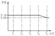
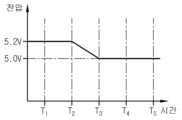
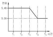
도 2 내지 도 5는 본 발명의 일 실시예에 따라 도 1의 장치(100)에 의해 복수의 배터리를 밸런싱하는 동작을 시계열적으로 설명하는 데에 참조되는 예시적인 그래프이다. 도 2 내지 도 5는 순서대로 배터리(20_1), 배터리(20_2), 배터리(20_3) 및 배터리(20_4)의 전압의 시간에 따른 변화를 보여준다. 설명의 편의를 위해, 배터리(20_4)의 전압은 5.4V이고, 배터리(20_3)의 전압은 5.2V 이며, 배터리(20_2)의 전압은 5.0V이고, 배터리(20_1)의 전압은 5.1V이며, 이진 감산기가 제2 카운터(162)로 이용되는 것으로 가정한다.FIGS. 2 to 5 are exemplary graphs referenced for explaining in time series the operation of balancing a plurality of batteries by the
도 1 및 도 2 내지 도 5와 표 1을 참조하면, 시점 T1에서 장치(100)가 기함에 따라, 제1 카운터(161)는 제1 카운트를 소정의 시작 카운트로 초기화할 수 있다. 시작 카운트는 1~4일 수 있으며, 본 예에서는 2라고 가정한다. 제2 카운트는 제1 카운트보다 1만큼 작은 1을 제2 카운터(162)로 결정한다. 카운팅 회로(160)는 제1 멀티플렉서(111) 및 제2 멀티플렉서(112)에게 "01"을 제1 선택 신호로서 "00"을 제2 선택 신호로서 각각 출력한다. 제1 멀티플렉서(111)는 제1 선택 신호인 "01"에 응답하여 배터리(20_2)를 선택하고, 제2 멀티플렉서(112)는 제2 선택 신호인 "00"에 응답하여 배터리(20_1)를 선택한다. 그러면, 제1 멀티플렉서(111)에 의해 선택된 배터리(20_2)의 전압인 5.0V를 나타내는 제1 디지털 신호 및 제2 멀티플렉서(112)에 의해 선택된 배터리(20_1)의 전압인 5.1V를 나타내는 제2 디지털 신호가 제1 아날로그 디지털 컨버터(141) 및 제2 아날로그 디지털 컨버터(142)에 의해 디지털 비교기(150)에게 출력된다. 디지털 비교기(150)는, 배터리(20_2)의 전압이 배터리(20_1)의 전압 이하인 것에 응답하여, 제2 레벨의 제어 신호를 출력한다. 제어 신호가 제2 레벨이므로, 방전 스위치(SW)는 오프 상태로 유지된다.Referring to FIGS. 1 and 2 to 5 and Table 1, as the
시점 T2에서, 제1 카운터(161)는, 제어 신호가 제2 레벨인 것에 응답하여, 제1 카운트를 2에서 3으로 증가시킨다. 제2 카운터(162)는, 제1 카운트가 3인 것에 응답하여, 제1 카운트보다 1만큼 작은 2를 제2 카운트로서 결정한다. 카운팅 회로(160)는 제1 멀티플렉서(111) 및 제2 멀티플렉서(112)에게 "10"을 제1 선택 신호로서 "01"을 제2 선택 신호로서 각각 출력한다. 제1 멀티플렉서(111)는 제1 선택 신호인 "10"에 응답하여 배터리(20_3)를 선택하고, 제2 멀티플렉서(112)는 제2 선택 신호인 "01"에 응답하여 배터리(20_2)를 선택한다. 그러면, 배터리(20_3)의 전압인 5.2V를 나타내는 제1 디지털 신호 및 배터리(20_2)의 전압인 5.0V를 나타내는 제2 디지털 신호가 제1 아날로그 디지털 컨버터(141) 및 제2 아날로그 디지털 컨버터(142)에 의해 디지털 비교기(150)에게 출력된다. 디지털 비교기(150)는, 배터리(20_3)의 전압이 배터리(20_2)의 전압보다 큰 것에 응답하여, 제1 레벨의 제어 신호를 출력한다. 제어 신호가 제1 레벨이므로, 방전 스위치(SW)는 오프 상태로부터 온 상태로 전이된다. 방전 스위치(SW)가 온 상태인 동안 방전 회로(120)에 의해 배터리(20_3)의 방전이 이루어지면서 배터리(20_3)의 전압이 점차적으로 낮아지다가 시점 T3에서 배터리(20_2)의 전압인 5.0V와 동일해진다. 디지털 비교기(150)는 배터리(20_3)의 전압이 배터리(20_2)의 전압과 동일해진 것에 응답하여, 제2 레벨의 제어 신호를 출력하며, 방전 스위치(SW)는 오프 상태로 전이된다.At time T2 ,
시점 T3에서, 제1 카운터(161)는, 제어 신호가 제2 레벨인 것에 응답하여, 제1 카운트를 3에서 임계 카운트인 4로 증가시킨다. 제2 카운터(162)는, 제1 카운트가 4인 것에 응답하여, 제1 카운트보다 1만큼 작은 3을 제2 카운트로서 결정한다. 카운팅 회로(160)는 제1 멀티플렉서(111) 및 제2 멀티플렉서(112)에게 "11"을 제1 선택 신호로서 "10"을 제2 선택 신호로서 각각 출력한다. 제1 멀티플렉서(111)는 제1 선택 신호인 "11"에 응답하여 배터리(20_4)를 선택하고, 제2 멀티플렉서(112)는 제2 선택 신호인 "10"에 응답하여 배터리(20_3)를 선택한다. 배터리(20_3)의 전압은, 시점 T2에서 시점 T3까지의 기간에 걸쳐 5.0V로 감소되어 있는 상태이다. 그러면, 배터리(20_4)의 전압인 5.4V를 나타내는 제1 디지털 신호 및 배터리(20_3)의 전압인 5.0V를 나타내는 제2 디지털 신호가 제1 아날로그 디지털 컨버터(141) 및 제2 아날로그 디지털 컨버터(142)에 의해 디지털 비교기(150)에게 출력된다. 디지털 비교기(150)는, 배터리(20_4)의 전압이 배터리(20_3)의 전압보다 큰 것에 응답하여, 제1 레벨의 제어 신호를 출력한다. 제어 신호가 제1 레벨이므로, 방전 스위치(SW)는 오프 상태로부터 온 상태로 전이된다. 방전 스위치(SW)가 온 상태인 동안 방전 회로(120)에 의해 배터리(20_4)의 방전이 이루어지면서 배터리(20_4)의 전압이 점차적으로 낮아지다가 시점 T4에서 배터리(20_3)의 전압인 5.0V와 동일해진다. 디지털 비교기(150)는, 배터리(20_4)의 전압이 배터리(20_3)의 전압과 동일해진 것에 응답하여, 제2 레벨의 제어 신호를 출력하며, 방전 스위치(SW)는 오프 상태로 전이된다.At time T3 ,
시점 T4에서, 제1 카운터(161)는, 제어 신호가 제2 레벨인 것에 응답하여, 제1 카운트를 임계 카운트인 4에서 1로 갱신시킨다. 제2 카운터(162)는, 제1 카운트가 1인 것에 응답하여, 임계 카운트인 4를 제2 카운트로 결정한다. 카운팅 회로(160)는 제1 멀티플렉서(111) 및 제2 멀티플렉서(112)에게 "00"을 제1 선택 신호로서 "11"을 제2 선택 신호로서 각각 출력한다. 제1 멀티플렉서(111)는 제1 선택 신호인 "00"에 응답하여 배터리(20_1)를 선택하고, 제2 멀티플렉서(112)는 제2 선택 신호인 "11"에 응답하여 배터리(20_4)를 선택한다. 그러면, 배터리(20_1)의 전압인 5.1V를 나타내는 제1 디지털 신호 및 배터리(20_4)의 전압인 5.0V를 나타내는 제2 디지털 신호가 제1 아날로그 디지털 컨버터(141) 및 제2 아날로그 디지털 컨버터(142)에 의해 디지털 비교기(150)에게 출력된다. 디지털 비교기(150)는, 배터리(20_1)의 전압이 배터리(20_4)의 전압보다 큰 것에 응답하여, 제1 레벨의 제어 신호를 출력한다. 제어 신호가 제1 레벨이므로, 방전 스위치(SW)는 오프 상태로부터 온 상태로 전이된다. 방전 스위치(SW)가 온 상태인 동안 방전 회로(120)에 의해 배터리(20_1)의 방전이 이루어지면서 배터리(20_1)의 전압이 점차적으로 낮아지다가 시점 T4에서 배터리(20_4)의 전압인 5.0V와 동일해진다. 디지털 비교기(150)는, 배터리(20_1)의 전압이 배터리(20_4)의 전압과 동일해진 것에 응답하여, 제2 레벨의 제어 신호를 출력하며, 방전 스위치(SW)는 오프 상태로 전이된다.At time T4 , the
도 2 내지 도 5를 참조하면, 시점 T4에서 복수의 배터리(20_1~20_4) 모두의 전압이 5.0V로 동일짐에 따라, 배터리 밸런싱은 완료될 수 있다.Referring to FIGS. 2 to 5 , as the voltages of all of the plurality of batteries 20_1 to 20_4 become equal to 5.0V at time T4 , battery balancing may be completed.
도 6 내지 도 9은 본 발명의 다른 실시예에 따라 도 1의 장치(100)에 의해 복수의 배터리를 밸런싱하는 동작을 시계열적으로 설명하는 데에 참조되는 예시적인 그래프이다. 도 6 내지 도 9는 순서대로 배터리(20_1), 배터리(20_2), 배터리(20_3) 및 배터리(20_4)의 전압의 시간에 따른 변화를 보여준다. 설명의 편의를 위해, 배터리(20_4)의 전압은 5.4V이고, 배터리(20_3)의 전압은 5.2V이며, 배터리(20_2)의 전압은 5.0V이고, 배터리(20_1)의 전압은 5.1V이며, 이진 가산기가 제2 카운터(162)로 이용되는 것으로 가정한다. 즉, 제2 카운터(162)가 이진 가산기라는 점에서 도 2 내지 도 5를 참조하여 전술한 제1 동작과 상이하다.FIGS. 6 to 9 are exemplary graphs referenced for explaining in time series the operation of balancing a plurality of batteries by the
도 1 및 도 6 내지 도 9와 표 2를 참조하면, 시점 T1에서 장치(100)가 기동함에 따라, 제1 카운터(161)는 제1 카운트를 소정의 시작 카운트(예, 1)로 초기화할 수 있다. 제2 카운트는 시작 카운트보다 1만큼 큰 2를 제2 카운트로 결정한다. 카운팅 회로(160)는 제1 멀티플렉서(111) 및 제2 멀티플렉서(112)에게 "00"을 제1 선택 신호로서 "01"을 제2 선택 신호로서 각각 출력한다. 제1 멀티플렉서(111)는 제1 선택 신호인 "00"에 응답하여 배터리(20_1)를 선택하고, 제2 멀티플렉서(112)는 제2 선택 신호인 "01"에 응답하여 배터리(20_2)를 선택한다. 그러면, 배터리(20_1)의 전압인 5.1V를 나타내는 제1 디지털 신호 및 배터리(20_2)의 전압인 5.0V를 나타내는 제2 디지털 신호가 제1 아날로그 디지털 컨버터(141) 및 제2 아날로그 디지털 컨버터(142)에 의해 디지털 비교기(150)에게 출력된다. 디지털 비교기(150)는, 배터리(20_1)의 전압이 배터리(20_2)보다 큰 것에 응답하여, 제1 레벨의 제어 신호를 출력한다. 제어 신호가 제1 레벨이므로, 방전 스위치(SW)는 오프 상태로부터 온 상태로 전이된다. 방전 스위치(SW)가 온 상태인 동안 방전 회로(120)에 의해 배터리(20_1)의 방전이 이루어지면서 배터리(20_1)의 전압이 점차적으로 낮아지다가 시점 T2에서 배터리(20_2)의 전압인 5.0V와 동일해진다. 디지털 비교기(150)는, 배터리(20_1)의 전압이 배터리(20_2)의 전압과 동일해진 것에 응답하여, 제2 레벨의 제어 신호를 출력하며, 방전 스위치(SW)는 오프 상태로 전이된다.Referring to FIGS. 1 and 6 to 9 and Table 2, as the
시점 T2에서, 제1 카운터(161)는, 제어 신호가 제2 레벨인 것에 응답하여, 제1 카운트를 1에서 2로 증가시킨다. 제2 카운터(162)는, 제1 카운트가 2인 것에 응답하여, 제1 카운트보다 1만큼 큰 3을 제2 카운트로서 결정한다. 카운팅 회로(160)는 제1 멀티플렉서(111) 및 제2 멀티플렉서(112)에게 "01"을 제1 선택 신호로서 "10"을 제2 선택 신호로서 각각 출력한다. 제1 멀티플렉서(111)는 제1 선택 신호인 "01"에 응답하여 배터리(20_2)를 선택하고, 제2 멀티플렉서(112)는 제2 선택 신호인 "10"에 응답하여 배터리(20_3)를 선택한다. 그러면, 배터리(20_2)의 전압인 5.0V를 나타내는 제1 디지털 신호 및 배터리(20_3)의 전압인 5.2V를 나타내는 제2 디지털 신호가 제1 아날로그 디지털 컨버터(141) 및 제2 아날로그 디지털 컨버터(142)에 의해 디지털 비교기(150)에게 출력된다. 디지털 비교기(150)는, 배터리(20_2)의 전압이 배터리(20_3)의 전압 이하인 것에 응답하여, 제2 레벨의 제어 신호를 출력한다.At time T2 ,
시점 T3에서, 제1 카운터(161)는, 제어 신호가 제2 레벨인 것에 응답하여, 제1 카운트를 2에서 3으로 증가시킨다. 제2 카운터(162)는, 제1 카운트가 3인 것에 응답하여, 제1 카운트보다 1만큼 큰 4를 제2 카운트로서 결정한다. 카운팅 회로(160)는, 제1 멀티플렉서(111) 및 제2 멀티플렉서(112)에게 "10"을 제1 선택 신호로서 "11"을 제2 선택 신호로서 각각 출력한다. 제1 멀티플렉서(111)는 제1 선택 신호인 "10"에 응답하여 배터리(20_3)를 선택하고, 제2 멀티플렉서(112)는 제2 선택 신호인 "11"에 응답하여 배터리(20_4)를 선택한다. 그러면, 배터리(20_3)의 전압인 5.2V를 나타내는 제1 디지털 신호 및 배터리(20_4)의 전압인 5.4V를 나타내는 제2 디지털 신호가 제1 아날로그 디지털 컨버터(141) 및 제2 아날로그 디지털 컨버터(142)에 의해 디지털 비교기(150)에게 출력된다. 디지털 비교기(150)는, 배터리(20_3)의 전압이 배터리(20_4)의 전압 이하인 것에 응답하여, 제2 레벨의 제어 신호를 출력한다.At time T3 ,
시점 T4에서, 제1 카운터(161)는, 제어 신호가 제2 레벨인 것에 응답하여, 제1 카운트를 3에서 임계 카운트인 4로 증가시킨다. 제2 카운터(162)는, 제1 카운트가 임계 카운트와 동일한 4인 것에 응답하여, 기준 카운트인 1을 제2 카운트로 결정한다. 카운팅 회로(160)는 제1 멀티플렉서(111) 및 제2 멀티플렉서(112)에게 "11"을 제1 선택 신호로서 "00"을 제2 선택 신호로서 각각 출력한다. 제1 멀티플렉서(111)는 제1 선택 신호인 "11"에 응답하여 배터리(20_4)를 선택하고, 제2 멀티플렉서(112)는 제2 선택 신호인 "00"에 응답하여 배터리(20_1)를 선택한다. 그러면, 배터리(20_4)의 전압인 5.4V를 나타내는 제1 디지털 신호 및 배터리(20_1)의 전압인 5.0V를 나타내는 제2 디지털 신호가 제1 아날로그 디지털 컨버터(141) 및 제2 아날로그 디지털 컨버터(142)에 의해 디지털 비교기(150)에게 출력된다. 디지털 비교기(150)는, 배터리(20_4)의 전압이 배터리(20_1)의 전압보다 큰 것에 응답하여, 제1 레벨의 제어 신호를 출력한다. 제어 신호가 제1 레벨이므로, 방전 스위치(SW)는 오프 상태로부터 온 상태로 전이된다. 방전 스위치(SW)가 온 상태인 동안 방전 회로(120)에 의해 배터리(20_4)의 방전이 이루어지면서 배터리(20_4)의 전압이 점차적으로 낮아지다가 시점 T5에서 배터리(20_1)의 전압인 5.0V와 동일해진다. 디지털 비교기(150)는, 배터리(20_4)의 전압이 배터리(20_1)의 전압과 동일해진 것에 응답하여, 제2 레벨의 제어 신호를 출력하며, 방전 스위치(SW)는 오프 상태로 전이된다.At time T4 ,
시점 T5에서, 제1 카운터(161)는, 제어 신호가 제2 레벨인 것에 응답하여, 제1 카운트를 4에서 1로 갱신한다. 제2 카운터(162)는, 제1 카운트가 1인 것에 응답하여, 제1 카운트보다 1만큼 큰 2를 제2 카운트로서 결정한다. 카운팅 회로(160)는 제1 멀티플렉서(111) 및 제2 멀티플렉서(112)에게 "00"을 제1 선택 신호로서 "01"을 제2 선택 신호로서 각각 출력한다. 제1 멀티플렉서(111)는 제1 선택 신호인 "00"에 응답하여 배터리(20_1)를 선택하고, 제2 멀티플렉서(112)는 제2 선택 신호인 "01"에 응답하여 배터리(20_2)를 선택한다. 배터리(20_1)의 전압은, 시점 T1에서 시점 T2까지의 기간에 걸쳐 5.0V로 감소되어 있는 상태이다. 그러면, 배터리(20_1)의 전압인 5.0V를 나타내는 제1 디지털 신호 및 배터리(20_2)의 전압인 5.0V를 나타내는 제2 디지털 신호가 제1 아날로그 디지털 컨버터(141) 및 제2 아날로그 디지털 컨버터(142)에 의해 디지털 비교기(150)에게 출력된다. 디지털 비교기(150)는, 배터리(20_3)의 전압이 배터리(20_4)의 전압 이하인 것에 응답하여, 제2 레벨의 제어 신호를 출력한다.At time T5 , the
시점 T6에서, 제1 카운터(161)는, 제어 신호가 제2 레벨인 것에 응답하여, 제1 카운트를 1에서 2로 증가시킨다. 제2 카운터(162)는, 제1 카운트가 2인 것에 응답하여, 제1 카운트보다 1만큼 큰 3을 제2 카운트로서 결정한다. 카운팅 회로(160)는 제1 멀티플렉서(111) 및 제2 멀티플렉서(112)에게 "01"을 제1 선택 신호로서 "10"을 제2 선택 신호로서 각각 출력한다. 제1 멀티플렉서(111)는 제1 선택 신호인 "01"에 응답하여 배터리(20_2)를 선택하고, 제2 멀티플렉서(112)는 제2 선택 신호인 "10"에 응답하여 배터리(20_3)를 선택한다. 그러면, 배터리(20_2)의 전압인 5.0V를 나타내는 제1 디지털 신호 및 배터리(20_3)의 전압인 5.2V를 나타내는 제2 디지털 신호가 제1 아날로그 디지털 컨버터(141) 및 제2 아날로그 디지털 컨버터(142)를 통해 디지털 비교기(150)에게 출력된다. 디지털 비교기(150)는, 배터리(20_2)의 전압이 배터리(20_3)의 전압 이하인 것에 응답하여, 제2 레벨의 제어 신호를 출력한다.At time T6 ,
시점 T7에서, 제1 카운터(161)는, 제어 신호가 제2 레벨인 것에 응답하여, 제1 카운트를 2에서 3으로 증가시킨다. 제2 카운터(162)는, 제1 카운트가 3인 것에 응답하여, 제1 카운트보다 1만큼 큰 4를 제2 카운트로서 결정한다. 카운팅 회로(160)는 제1 멀티플렉서(111) 및 제2 멀티플렉서(112)에게 "10"을 제1 선택 신호로서 "11"을 제2 선택 신호로서 각각 출력한다. 제1 멀티플렉서(111)는 제1 선택 신호인 "10"에 응답하여 배터리(20_3)를 선택하고, 제2 멀티플렉서(112)는 제2 선택 신호인 "11"에 응답하여 배터리(20_4)를 선택한다. 배터리(20_4)의 전압은, 시점 T4에서 시점 T5까지의 기간에 걸쳐 5.0V로 감소되어 있는 상태이다. 그러면, 배터리(20_3)의 전압인 5.2V를 나타내는 제1 디지털 신호 및 배터리(20_4)의 전압인 5.0V를 나타내는 제2 디지털 신호가 제1 아날로그 디지털 컨버터(141) 및 제2 아날로그 디지털 컨버터(142)를 통해 디지털 비교기(150)에게 출력된다. 디지털 비교기(150)는, 배터리(20_3)의 전압이 배터리(20_4)의 전압 이하인 것에 응답하여, 제1 레벨의 제어 신호를 출력한다. 제어 신호가 제1 레벨이므로, 방전 스위치(SW)는 오프 상태로부터 온 상태로 전이된다. 방전 스위치(SW)가 온 상태인 동안 방전 회로(120)에 의해 배터리(20_3)의 방전이 이루어지면서 배터리(20_3)의 전압이 점차적으로 낮아지다가 시점 T8에서 배터리(20_4)의 전압인 5.0V와 동일해진다. 디지털 비교기(150)는, 배터리(20_3)의 전압이 배터리(20_4)의 전압과 동일해진 것에 응답하여, 제2 레벨의 제어 신호를 출력하며, 방전 스위치(SW)는 오프 상태로 전이된다.At time T7 ,
도 6 내지 도 9를 참조하면, 시점 T8에서 복수의 배터리(20_1~20_4) 모두의 전압이 5.0V로 동일짐에 따라, 배터리 밸런싱은 완료될 수 있다.Referring to FIGS. 6 to 9 , as the voltages of all of the plurality of batteries 20_1 to 20_4 become equal to 5.0V at time T8 , battery balancing may be completed.
전술한 실시예들에 의하면, 단일의 저항 소자(R)를 이용하여 복수의 배터리(20_1~20_n)를 밸런싱할 수 있다. 이에 따라, 배터리팩(10)의 공간 활용성이 개선되고, 배터리팩(10)의 에너지 밀도를 증대할 수 있다.According to the above-described embodiments, a plurality of batteries 20_1 to 20_n can be balanced using a single resistance element R. Accordingly, the space utilization of the
또한, 배터리 밸런싱을 위한 소프트웨어의 실행없이도 복수의 배터리(20_1~20_n)를 밸런싱할 수 있다. 이에 따라, 소프트웨어의 실행 오류로부터 자유로워질 수 있다.Additionally, multiple batteries (20_1 to 20_n) can be balanced without running software for battery balancing. Accordingly, you can be free from software execution errors.
이상에서 본 발명은 비록 한정된 실시예와 도면에 의해 설명되었으나, 본 발명은 이것에 의해 한정되지 않으며 본 발명이 속하는 기술분야에서 통상의 지식을 가진 자에 의해 본 발명의 기술사상과 아래에 기재될 특허청구범위의 균등범위 내에서 다양한 수정 및 변형이 가능함은 물론이다.Although the present invention has been described above with limited examples and drawings, the present invention is not limited thereto, and the technical idea of the present invention and the description below will be understood by those skilled in the art to which the present invention pertains. Of course, various modifications and variations are possible within the scope of equivalence of the patent claims.
또한, 이상에서 설명한 본 발명은 본 발명이 속하는 기술분야에서 통상의 지식을 가진 자에 있어 본 발명의 기술적 사상을 벗어나지 않는 범위 내에서 여러 가지 치환, 변형 및 변경이 가능하므로 전술한 실시예 및 첨부된 도면에 의해 한정되는 것이 아니라, 다양한 변형이 이루어질 수 있도록 각 실시예들의 전부 또는 일부가 선택적으로 조합되어 구성될 수 있다.In addition, the present invention described above is capable of various substitutions, modifications, and changes without departing from the technical spirit of the present invention to those of ordinary skill in the technical field to which the present invention pertains. It is not limited by the drawings, and all or part of each embodiment can be selectively combined so that various modifications can be made.
10: 배터리팩
G: 배터리 그룹
20: 배터리
100: 장치
110: 배터리 선택 회로
111, 112: 멀티플렉서
120: 방전 회로
R: 저항 소자
SW: 방전 스위치
130: 제어 회로
141, 142: 아날로그 디지털 컨버터
150: 디지털 비교기
160: 카운팅 회로
161: 제1 카운터
162: 제2 카운터10: Battery pack
G: Battery group
20: battery
100: device
110: Battery selection circuit
111, 112: Multiplexer
120: discharge circuit
R: resistance element
SW: discharge switch
130: control circuit
141, 142: Analog digital converter
150: digital comparator
160: Counting circuit
161: 1st counter
162: Second counter
Claims (10)
Translated fromKorean상기 제1 내지 제n 배터리에 전기적으로 연결되고, 제1 선택 신호 및 제2 선택 신호에 응답하여 상기 제1 내지 제n 배터리 중 어느 둘을 선택하도록 구성된 배터리 선택 회로;
전기적으로 직렬 연결된 저항 소자 및 방전 스위치를 포함하고, 상기 배터리 선택 회로에 의해 상기 선택된 두 배터리 중 상기 제1 선택 신호에 따라 선택된 배터리에만 전기적으로 병렬 연결되는 방전 회로; 및
상기 배터리 선택 회로 및 상기 방전 스위치에 동작 가능하게 결합되는 제어 회로를 포함하고,
상기 제어 회로는,
상기 선택된 두 배터리 중 상기 제1 선택 신호에 따라 선택된 배터리의 전압인 제1 전압이 상기 선택된 두 배터리 중 상기 제2 선택 신호에 따라 선택된 배터리의 전압인 제2 전압보다 큰 경우, 제1 레벨을 갖는 제어 신호를 출력하고,
상기 제1 전압이 상기 제2 전압 이하인 경우, 제2 레벨을 갖는 제어 신호를 출력하도록 구성되되,
상기 방전 스위치는,
상기 제어 신호가 상기 제1 레벨이면 온 상태가 되고, 상기 제어 신호가 상기 제2 레벨이면 오프 상태가 되고,
상기 제어 회로는,
상기 제1 전압이 상기 제2 전압보다 크면, 상기 제1 선택 신호 및 상기 제2 선택 신호에 따라 상기 배터리 선택 회로에 의해 선택되는 두 배터리가 동일하도록 상기 제1 선택 신호의 값 및 상기 제2 선택 신호의 값을 유지하고,
상기 제1 전압이 상기 제2 전압 이하이면, 상기 제1 선택 신호 및 상기 제2 선택 신호에 따라 상기 배터리 선택 회로에 의해 선택되는 두 배터리가 변경되도록 상기 제1 선택 신호 및 상기 제2 선택 신호의 값을 증가 또는 감소시키도록 구성되는, 장치.
In a device for balancing first to nth batteries (n is an integer of 3 or more) connected in series,
a battery selection circuit electrically connected to the first to nth batteries and configured to select any two of the first to nth batteries in response to a first selection signal and a second selection signal;
a discharge circuit including a resistor element and a discharge switch electrically connected in series, and electrically connected in parallel only to the battery selected according to the first selection signal among the two batteries selected by the battery selection circuit; and
a control circuit operably coupled to the battery selection circuit and the discharge switch;
The control circuit is,
When the first voltage, which is the voltage of the battery selected according to the first selection signal among the two selected batteries, is greater than the second voltage, which is the voltage of the battery selected according to the second selection signal among the two selected batteries, it has a first level. output a control signal,
When the first voltage is less than or equal to the second voltage, it is configured to output a control signal having a second level,
The discharge switch is,
When the control signal is at the first level, it is in an on state, and when the control signal is at the second level, it is in an off state,
The control circuit is,
When the first voltage is greater than the second voltage, the value of the first selection signal and the second selection signal are the same so that the two batteries selected by the battery selection circuit according to the first selection signal and the second selection signal are the same. maintain the value of the signal,
When the first voltage is less than or equal to the second voltage, the first selection signal and the second selection signal are changed so that the two batteries selected by the battery selection circuit are changed according to the first selection signal and the second selection signal. A device configured to increase or decrease a value.
상기 배터리 선택 회로는,
제1 출력핀 및 제2 출력핀을 구비하고, 상기 제1 선택 신호에 따라 선택된 배터리의 양극 단자 및 음극 단자를 상기 제1 출력핀 및 상기 제2 출력핀에 전기적으로 연결하도록 구성된 제1 멀티플렉서; 및
제3 출력핀 및 제4 출력핀을 구비하고, 상기 제2 선택 신호에 따라 선택된 배터리의 양극 단자 및 음극 단자를 상기 제3 출력핀 및 상기 제4 출력핀에 전기적으로 연결하도록 구성된 제2 멀티플렉서를 포함하는, 장치.
According to paragraph 1,
The battery selection circuit is,
a first multiplexer having a first output pin and a second output pin, and configured to electrically connect a positive terminal and a negative terminal of a battery selected according to the first selection signal to the first output pin and the second output pin; and
A second multiplexer having a third output pin and a fourth output pin, and configured to electrically connect the positive and negative terminals of the battery selected according to the second selection signal to the third output pin and the fourth output pin. Including device.
상기 제어 회로는,
상기 제1 출력핀 및 상기 제2 출력핀에 전기적으로 연결되고, 상기 제1 전압을 나타내는 제1 디지털 신호를 출력하도록 구성된 제1 아날로그 디지털 컨버터;
상기 제3 출력핀 및 상기 제4 출력핀에 전기적으로 연결되고, 상기 제2 전압을 나타내는 제2 디지털 신호를 출력하도록 구성된 제2 아날로그 디지털 컨버터;
상기 제1 디지털 신호 및 상기 제2 디지털 신호를 기초로, 상기 제어 신호를 출력하도록 구성된 디지털 비교기; 및
상기 제어 신호에 응답하여, 상기 제1 선택 신호 및 상기 제2 선택 신호를 출력하도록 구성된 카운팅 회로를 포함하는, 장치.
According to paragraph 2,
The control circuit is,
a first analog-to-digital converter electrically connected to the first output pin and the second output pin and configured to output a first digital signal representing the first voltage;
a second analog-to-digital converter electrically connected to the third output pin and the fourth output pin and configured to output a second digital signal representing the second voltage;
a digital comparator configured to output the control signal based on the first digital signal and the second digital signal; and
and a counting circuit configured to output the first selection signal and the second selection signal in response to the control signal.
상기 카운팅 회로는,
상기 제어 신호가 상기 제1 레벨인 것에 응답하여, 제1 카운트 및 제2 카운트를 유지하도록 구성되고,
상기 제어 신호가 상기 제2 레벨인 것에 응답하여, 상기 제1 카운트 및 상기 제2 카운트를 증가 또는 감소시키도록 구성된, 장치.
According to paragraph 3,
The counting circuit is,
configured to maintain a first count and a second count in response to the control signal being at the first level;
Apparatus configured to increase or decrease the first count and the second count in response to the control signal being at the second level.
상기 카운팅 회로는,
상기 제어 신호가 상기 제2 레벨인 것에 응답하여, 상기 제1 카운트를 증가 또는 감소시키도록 구성된 제1 카운터; 및
상기 제1 카운터에 동작 가능하게 결합되고, 상기 제1 카운터로부터의 상기 제1 카운트를 기초로 상기 제2 카운트를 결정하도록 구성된 제2 카운터를 포함하는, 장치.
According to paragraph 4,
The counting circuit is,
a first counter configured to increase or decrease the first count in response to the control signal being at the second level; and
and a second counter operably coupled to the first counter and configured to determine the second count based on the first count from the first counter.
상기 제2 카운터는,
상기 제1 카운트에서 1을 빼 상기 제2 카운트를 결정하도록 구성된 이진 감산기를 포함하는, 장치.
According to clause 5,
The second counter is,
and a binary subtractor configured to subtract 1 from the first count to determine the second count.
상기 제2 카운터는,
상기 제1 카운트가 기준 카운트가 된 것에 응답하여, 임계 카운트를 상기 제2 카운트로서 결정하도록 구성된, 장치.
According to clause 6,
The second counter is,
In response to the first count becoming a reference count, determine a threshold count as the second count.
상기 제2 카운터는,
상기 제1 카운트에 1을 더해 상기 제2 카운트를 결정하도록 구성된 이진 가산기를 포함하는, 장치.
According to clause 5,
The second counter is,
and a binary adder configured to add 1 to the first count to determine the second count.
상기 제2 카운터는,
상기 제1 카운트가 임계 카운트가 된 것에 응답하여, 기준 카운트를 상기 제2 카운트로서 결정하도록 구성된, 장치.
According to clause 8,
The second counter is,
In response to the first count becoming a threshold count, determine a reference count as the second count.
A battery pack comprising the device according to any one of claims 1 to 9.
Priority Applications (1)
| Application Number | Priority Date | Filing Date | Title |
|---|---|---|---|
| KR1020180101580AKR102648319B1 (en) | 2018-08-28 | 2018-08-28 | Apparatus for battery balancing and battery pack including the same |
Applications Claiming Priority (1)
| Application Number | Priority Date | Filing Date | Title |
|---|---|---|---|
| KR1020180101580AKR102648319B1 (en) | 2018-08-28 | 2018-08-28 | Apparatus for battery balancing and battery pack including the same |
Publications (2)
| Publication Number | Publication Date |
|---|---|
| KR20200024648A KR20200024648A (en) | 2020-03-09 |
| KR102648319B1true KR102648319B1 (en) | 2024-03-14 |
Family
ID=69802146
Family Applications (1)
| Application Number | Title | Priority Date | Filing Date |
|---|---|---|---|
| KR1020180101580AActiveKR102648319B1 (en) | 2018-08-28 | 2018-08-28 | Apparatus for battery balancing and battery pack including the same |
Country Status (1)
| Country | Link |
|---|---|
| KR (1) | KR102648319B1 (en) |
Citations (3)
| Publication number | Priority date | Publication date | Assignee | Title |
|---|---|---|---|---|
| JP2010081777A (en) | 2008-09-29 | 2010-04-08 | Mazda Motor Corp | Controlling apparatus and method of battery cell |
| JP2013108991A (en)* | 2009-02-27 | 2013-06-06 | Hitachi Ltd | Battery monitoring device |
| JP2018050454A (en)* | 2011-05-31 | 2018-03-29 | 日立オートモティブシステムズ株式会社 | Battery system monitoring device |
Family Cites Families (3)
| Publication number | Priority date | Publication date | Assignee | Title |
|---|---|---|---|---|
| KR101107999B1 (en)* | 2007-10-16 | 2012-01-25 | 한국과학기술원 | Battery Operating System Combines Voltage Sensor and Charge Uniformity |
| KR101076786B1 (en)* | 2009-01-30 | 2011-10-25 | 한국과학기술원 | Charge Equalization Apparatus for Series-Connected Battery String and Charge Equalization Method Thereof |
| KR20180035080A (en)* | 2016-09-28 | 2018-04-05 | 한국단자공업 주식회사 | Battery cell balancing circuit |
- 2018
- 2018-08-28KRKR1020180101580Apatent/KR102648319B1/enactiveActive
Patent Citations (3)
| Publication number | Priority date | Publication date | Assignee | Title |
|---|---|---|---|---|
| JP2010081777A (en) | 2008-09-29 | 2010-04-08 | Mazda Motor Corp | Controlling apparatus and method of battery cell |
| JP2013108991A (en)* | 2009-02-27 | 2013-06-06 | Hitachi Ltd | Battery monitoring device |
| JP2018050454A (en)* | 2011-05-31 | 2018-03-29 | 日立オートモティブシステムズ株式会社 | Battery system monitoring device |
Also Published As
| Publication number | Publication date |
|---|---|
| KR20200024648A (en) | 2020-03-09 |
Similar Documents
| Publication | Publication Date | Title |
|---|---|---|
| US7928691B2 (en) | Method and system for cell equalization with isolated charging sources | |
| US7825629B2 (en) | Method and system for cell equalization with charging sources and shunt regulators | |
| US8933667B2 (en) | Apparatus and method for controlling connection of battery packs | |
| US8129952B2 (en) | Battery systems and operational methods | |
| US8450973B2 (en) | Lithium battery module | |
| US20090309544A1 (en) | Method and system for cell equalization with switched charging sources | |
| EP3806271A1 (en) | Battery balancing device and battery pack including same | |
| CN110880622A (en) | Equalization control method of battery pack | |
| CN111886772A (en) | Balancing device, battery management system and battery pack including the same | |
| US9935472B2 (en) | Battery pack | |
| EP3849046A1 (en) | Electricity storage device and charging method | |
| CN106329613B (en) | Charge/discharge control circuit, charge/discharge control device, and battery device | |
| US20120032513A1 (en) | Battery management circuit, battery module and battery management method | |
| US20200358059A1 (en) | Battery Pack System Including Multi-Battery | |
| CN110915095A (en) | Battery pack management | |
| KR20220009547A (en) | Cell balancing apparatus of battery module | |
| CN108551180A (en) | Battery equalization method and balanced device | |
| KR102591062B1 (en) | Apparatus and method for balancing deterioration of battery | |
| KR102648319B1 (en) | Apparatus for battery balancing and battery pack including the same | |
| KR20180035080A (en) | Battery cell balancing circuit | |
| JP2016040999A (en) | Charge state equalization method for storage battery device | |
| KR102587974B1 (en) | Apparatus and method for changing the serial connection order among a plurality of batteries and battery pack including the apparatus | |
| TWI405385B (en) | Battery-charging equalization circuit, battery cell, and battery-charging equalization method | |
| US11641116B2 (en) | Charge/discharge control circuit and battery device having the same | |
| US11539221B2 (en) | Charge-discharge control circuit including cell balancing circuits, cell balance detection circuits, overcharge detection circuits, and a control circuit |
Legal Events
| Date | Code | Title | Description |
|---|---|---|---|
| PA0109 | Patent application | Patent event code:PA01091R01D Comment text:Patent Application Patent event date:20180828 | |
| PG1501 | Laying open of application | ||
| PN2301 | Change of applicant | Patent event date:20210512 Comment text:Notification of Change of Applicant Patent event code:PN23011R01D | |
| E902 | Notification of reason for refusal | ||
| PE0902 | Notice of grounds for rejection | Comment text:Notification of reason for refusal Patent event date:20230807 Patent event code:PE09021S01D | |
| E701 | Decision to grant or registration of patent right | ||
| PE0701 | Decision of registration | Patent event code:PE07011S01D Comment text:Decision to Grant Registration Patent event date:20240207 | |
| GRNT | Written decision to grant | ||
| PR0701 | Registration of establishment | Comment text:Registration of Establishment Patent event date:20240312 Patent event code:PR07011E01D | |
| PR1002 | Payment of registration fee | Payment date:20240312 End annual number:3 Start annual number:1 | |
| PG1601 | Publication of registration |