KR102646815B1 - Optical system of augmented reality glasses with saw tooth-type partial reflector array - Google Patents
Optical system of augmented reality glasses with saw tooth-type partial reflector arrayDownload PDFInfo
- Publication number
- KR102646815B1 KR102646815B1KR1020230047991AKR20230047991AKR102646815B1KR 102646815 B1KR102646815 B1KR 102646815B1KR 1020230047991 AKR1020230047991 AKR 1020230047991AKR 20230047991 AKR20230047991 AKR 20230047991AKR 102646815 B1KR102646815 B1KR 102646815B1
- Authority
- KR
- South Korea
- Prior art keywords
- image light
- optical system
- angle
- augmented reality
- sawtooth structure
- Prior art date
- Legal status (The legal status is an assumption and is not a legal conclusion. Google has not performed a legal analysis and makes no representation as to the accuracy of the status listed.)
- Active
Links
Images


Classifications
- G—PHYSICS
- G02—OPTICS
- G02B—OPTICAL ELEMENTS, SYSTEMS OR APPARATUS
- G02B27/00—Optical systems or apparatus not provided for by any of the groups G02B1/00 - G02B26/00, G02B30/00
- G02B27/01—Head-up displays
- G02B27/017—Head mounted
- G02B27/0172—Head mounted characterised by optical features
- G—PHYSICS
- G02—OPTICS
- G02B—OPTICAL ELEMENTS, SYSTEMS OR APPARATUS
- G02B6/00—Light guides; Structural details of arrangements comprising light guides and other optical elements, e.g. couplings
- G02B6/24—Coupling light guides
- G02B6/26—Optical coupling means
- G02B6/27—Optical coupling means with polarisation selective and adjusting means
- G02B6/2753—Optical coupling means with polarisation selective and adjusting means characterised by their function or use, i.e. of the complete device
- G—PHYSICS
- G02—OPTICS
- G02B—OPTICAL ELEMENTS, SYSTEMS OR APPARATUS
- G02B27/00—Optical systems or apparatus not provided for by any of the groups G02B1/00 - G02B26/00, G02B30/00
- G02B27/01—Head-up displays
- G—PHYSICS
- G02—OPTICS
- G02B—OPTICAL ELEMENTS, SYSTEMS OR APPARATUS
- G02B27/00—Optical systems or apparatus not provided for by any of the groups G02B1/00 - G02B26/00, G02B30/00
- G02B27/09—Beam shaping, e.g. changing the cross-sectional area, not otherwise provided for
- G02B27/0938—Using specific optical elements
- G02B27/095—Refractive optical elements
- G02B27/0955—Lenses
- G—PHYSICS
- G02—OPTICS
- G02B—OPTICAL ELEMENTS, SYSTEMS OR APPARATUS
- G02B27/00—Optical systems or apparatus not provided for by any of the groups G02B1/00 - G02B26/00, G02B30/00
- G02B27/09—Beam shaping, e.g. changing the cross-sectional area, not otherwise provided for
- G02B27/0938—Using specific optical elements
- G02B27/0977—Reflective elements
- G—PHYSICS
- G02—OPTICS
- G02B—OPTICAL ELEMENTS, SYSTEMS OR APPARATUS
- G02B27/00—Optical systems or apparatus not provided for by any of the groups G02B1/00 - G02B26/00, G02B30/00
- G02B27/10—Beam splitting or combining systems
- G02B27/14—Beam splitting or combining systems operating by reflection only
- G02B27/145—Beam splitting or combining systems operating by reflection only having sequential partially reflecting surfaces
- G—PHYSICS
- G02—OPTICS
- G02B—OPTICAL ELEMENTS, SYSTEMS OR APPARATUS
- G02B27/00—Optical systems or apparatus not provided for by any of the groups G02B1/00 - G02B26/00, G02B30/00
- G02B27/28—Optical systems or apparatus not provided for by any of the groups G02B1/00 - G02B26/00, G02B30/00 for polarising
- G02B27/286—Optical systems or apparatus not provided for by any of the groups G02B1/00 - G02B26/00, G02B30/00 for polarising for controlling or changing the state of polarisation, e.g. transforming one polarisation state into another
- G—PHYSICS
- G02—OPTICS
- G02B—OPTICAL ELEMENTS, SYSTEMS OR APPARATUS
- G02B6/00—Light guides; Structural details of arrangements comprising light guides and other optical elements, e.g. couplings
- G02B6/0001—Light guides; Structural details of arrangements comprising light guides and other optical elements, e.g. couplings specially adapted for lighting devices or systems
- G02B6/0011—Light guides; Structural details of arrangements comprising light guides and other optical elements, e.g. couplings specially adapted for lighting devices or systems the light guides being planar or of plate-like form
- G02B6/0033—Means for improving the coupling-out of light from the light guide
- G02B6/0056—Means for improving the coupling-out of light from the light guide for producing polarisation effects, e.g. by a surface with polarizing properties or by an additional polarizing elements
- G—PHYSICS
- G02—OPTICS
- G02B—OPTICAL ELEMENTS, SYSTEMS OR APPARATUS
- G02B6/00—Light guides; Structural details of arrangements comprising light guides and other optical elements, e.g. couplings
- G02B6/24—Coupling light guides
- G02B6/26—Optical coupling means
- G02B6/262—Optical details of coupling light into, or out of, or between fibre ends, e.g. special fibre end shapes or associated optical elements
- G—PHYSICS
- G06—COMPUTING OR CALCULATING; COUNTING
- G06T—IMAGE DATA PROCESSING OR GENERATION, IN GENERAL
- G06T19/00—Manipulating 3D models or images for computer graphics
- G06T19/006—Mixed reality
- G—PHYSICS
- G02—OPTICS
- G02B—OPTICAL ELEMENTS, SYSTEMS OR APPARATUS
- G02B27/00—Optical systems or apparatus not provided for by any of the groups G02B1/00 - G02B26/00, G02B30/00
- G02B27/01—Head-up displays
- G02B27/0101—Head-up displays characterised by optical features
- G02B2027/0123—Head-up displays characterised by optical features comprising devices increasing the field of view
- G—PHYSICS
- G02—OPTICS
- G02B—OPTICAL ELEMENTS, SYSTEMS OR APPARATUS
- G02B27/00—Optical systems or apparatus not provided for by any of the groups G02B1/00 - G02B26/00, G02B30/00
- G02B27/01—Head-up displays
- G02B27/017—Head mounted
- G02B2027/0178—Eyeglass type
Landscapes
- Physics & Mathematics (AREA)
- General Physics & Mathematics (AREA)
- Optics & Photonics (AREA)
- Engineering & Computer Science (AREA)
- Computer Graphics (AREA)
- Computer Hardware Design (AREA)
- General Engineering & Computer Science (AREA)
- Software Systems (AREA)
- Theoretical Computer Science (AREA)
Abstract
Description
Translated fromKorean본 발명은 헤드 마운트 디스플레이에 관한 것으로, 보다 상세하게는 영상광과 외부 이미지광을 높은 투과율로 사용자의 눈에 투사할 수 있는 톱니구조의 부분반사 어레이를 갖는 증강현실 글라스의 광학 시스템에 관한 것이다.The present invention relates to a head-mounted display, and more specifically, to an optical system of augmented reality glasses having a partially reflective array with a sawtooth structure that can project image light and external image light to the user's eyes with high transmittance.
일반적으로, 헤드 마운트 디스플레이(Head Mounted Display, HMD)는 사용자의 머리에 착용한 상태에서 영상을 디스플레이 하는 장치이다. 최근, 헤드 마운트 디스플레이를 사용하여 가상 현실 또는 증강 현실의 콘텐츠를 제공하는 기술이 증가하고 있다.In general, a head mounted display (HMD) is a device that displays images while worn on the user's head. Recently, technology for providing virtual reality or augmented reality content using head-mounted displays is increasing.
이러한 헤드 마운트 디스플레이에는 회절 도파관을 이용한 투과형 HMD 광학 시스템이 적용된다. 도 1은 종래의 출사동 확장 회절광학계의 개념도이다. 도 1에 도시된 바와 같이, 회절 도광판(10)은 광가이드부(11)와, 광가이드부(11)의 일면 또는 타면 측에 마련되며 복수의 선형 미세격자 패턴을 갖는 복수의 회절 광학소자(12, 13, 14)를 구비할 수 있다. 회절 도광판(10)은 광원출력모듈(5)을 통해 출력된 광이 입력되어 광가이드부(11) 상에 안내되도록 하는 입력 회절 광학소자(12)와, 광가이드부(11)를 통해 입력 회절 광학소자(12)와 광학적으로 커플링되며 입력 회절 광학소자(12)로부터 수광된 광을 회절에 의해 제1방향(도 1에서의 x축 방향)으로의 1차원적인 확장이 이루어질 수 있도록 하는 중간 회절 광학소자(13) 및 광가이드부(11)를 통해 중간 회절 광학소자(13)와 광학적으로 커플링되며 중간 회절 광학소자(13)로부터 수광된 광을 회절에 의해 제2방향(도 1에서의 y축 방향)으로의 1차원적인 확장이 이루어진 채 광가이드부(11)로부터 출력되어 사용자(15)의 동공으로 향할 수 있도록 하는 출력 회절 광학소자(14)를 구비하고 있다.A transmissive HMD optical system using a diffractive waveguide is applied to this head-mounted display. Figure 1 is a conceptual diagram of a conventional exit pupil expansion diffraction optical system. As shown in FIG. 1, the diffractive
이러한 종래의 회절광학계는 광원출력모듈(5)을 통해 출력된 광이 사용자(15)의 동공으로 도달하기 위한 주된 광경로는, 입력 회절 광학소자(12) - 중간 회절 광학소자(13) - 출력 회절 광학소자(14) - 사용자(15)의 동공 순이다. 최초의 입력 회절 광학소자(12)의 면적 대비 최종 출력 회절 광학소자(14)에서 출력되는 출력광의 면적이 수평(x축방향) 및 수직(y축 방향) 모두 훨씬 크기 때문에 수평 및 수직 출사동(eye-box) 확장이 이루어져 사용자는 보다 편하게 출력되는 영상광을 시청할 수 있는 특징을 가진다. 여기서 출사동이란 최대의 시야각으로 동일한 영상광을 볼 수 있는 가장 넓은 면적 크기를 말하며, 출사동의 크기가 클수록 사용자(15)의 동공을 위치시킬 수 있는 범위가 커져 사용자는 사용 편의성을 높일 수 있다.In this conventional diffractive optical system, the main optical path for the light output through the light
그러나, 이와 같은 종래의 출사동 확장 회절광학계는 입력 회절 광학소자(12), 중간 회절 광학소자(13) 및 출력 회절 광학소자(14)가 광가이드부(11) 상에서 서로 분리되어 배치되며 영상광의 입력에서 출력까지 많은 내부전반사와 회절이 이루어지므로 광가이드(11) 표면과 각 회절 광학소자(12, 13, 14)가 매우 정밀하게 가공되어야만 했다. 만약 그렇지 않으면 영상에 이중상이 생기거나 선명하지 않은 상을 출력할 가능성이 매우 높아 양산성이 매우 떨어지는 단점이 있다.However, in such a conventional exit pupil expansion diffractive optical system, the input diffractive
또한, 회절의 물리적 특성상 원하는 각도의 회절 광량이 기하광학을 통한 반사광량 보다 매우 적을 뿐 아니라, 총 3회의 회절반응을 통해 이미지 광이 출력되므로 광효율이 매우 떨어졌다. 이로 인해, 매우 강한 입사광을 사용해야 하는 단점을 추가로 가진다. 또한 회절이 여러 방향으로 이루어지므로 사용자(15)의 동공 방향뿐만 아니라 반대 방향으로도 출력광이 생기므로 외부에서 사용자가 보고 있는 화면을 동시에 볼 수 있어 보안에 문제가 생길 수도 있었다.In addition, due to the physical characteristics of diffraction, not only was the amount of diffracted light at the desired angle much smaller than the amount of reflected light through geometric optics, but the image light was output through a total of three diffraction reactions, so light efficiency was very low. Because of this, it has the additional disadvantage of having to use very strong incident light. In addition, since diffraction occurs in multiple directions, output light is generated not only in the direction of the user's pupil, but also in the opposite direction, so the screen that the user is viewing can be viewed from the outside at the same time, which could cause a security problem.
따라서, 본 발명은 상기와 같은 문제점을 해결하기 위하여 안출된 것으로서, 본 발명의 제 1 목적은, 광의 물질 내부 전반사를 통해 영상광을 접는 효과가 있는 도파로를 적용해 부피와 무게를 최소화하고, 영상광의 출사동 재활성화 방식으로 출사동 크기를 확장할 수 있는 톱니구조의 부분반사 어레이를 갖는 증강현실 글라스의 광학 시스템을 제공하는 것이다.Accordingly, the present invention was developed to solve the above problems, and the first purpose of the present invention is to minimize the volume and weight by applying a waveguide that has the effect of folding image light through total internal reflection of the light material, and to provide image The aim is to provide an optical system of augmented reality glass having a partial reflection array with a sawtooth structure that can expand the size of the exit pupil by reactivating the exit pupil of light.
본 발명의 제 2 목적은, 광 손실이 많은 회절광학 수단을 배제하고 기하광학적 반사면을 적용하여 광효율을 최대화함으로써 전력손실을 줄이고 밝은 화면을 제공할 수 있는 톱니구조의 부분반사 어레이를 갖는 증강현실 글라스의 광학 시스템을 제공하는 것이다.The second object of the present invention is an augmented reality with a sawtooth-structured partial reflection array that can reduce power loss and provide a bright screen by excluding diffractive optical means with high light loss and maximizing light efficiency by applying geometric optical reflection surfaces. It provides an optical system of glass.
또한, 본 발명의 제 3 목적은, 톱니형 부분반사 어레이 구조를 내장하여 도파로 내 영상광 추출 수단의 구조를 단순화하여 플라스틱 사출 양산이 가능하도록 하고, 톱니구조 전체에 균일한 기능성 코팅을 적용하여 반사 어레이를 제조함으로써 제품의 단가를 낮춰 가격경쟁력을 갖춘 톱니구조의 부분반사 어레이를 갖는 증강현실 글라스의 광학 시스템을 제공하는 것이다.In addition, the third object of the present invention is to simplify the structure of the image light extraction means in the waveguide by embedding a sawtooth partial reflection array structure to enable plastic injection mass production, and to apply a uniform functional coating to the entire sawtooth structure to achieve reflection. By manufacturing the array, the unit cost of the product is lowered and the optical system of augmented reality glass with a partially reflective array with a sawtooth structure is provided with price competitiveness.
본 발명의 제 4 목적은, 톱니 구조 상에 각도 편향성을 가지는 편광 코팅을 적용함으로써 사용자의 동공으로 향하는 영상광의 추출 효율을 높일 뿐 아니라, 동공 반대방향으로 출력되는 광경로를 차단함으로써 외부에서 사용자가 시청하는 동일한 영상을 볼 수 없도록 하여 보안이 강화된 광학시스템을 제공하는 것이다.The fourth object of the present invention is to not only increase the extraction efficiency of image light heading toward the user's pupil by applying a polarizing coating with angular bias on the sawtooth structure, but also block the optical path output in the direction opposite to the pupil, thereby preventing the user from outside from outside. It provides an optical system with enhanced security by preventing users from seeing the same video they are watching.
다만, 본 발명에서 이루고자 하는 기술적 과제들은 이상에서 언급한 기술적 과제들로 제한되지 않으며, 언급하지 않은 또 다른 기술적 과제들은 아래의 기재로부터 본 발명이 속하는 기술분야에서 통상의 지식을 가진 자에게 명확하게 이해될 수 있을 것이다.However, the technical problems to be achieved in the present invention are not limited to the technical problems mentioned above, and other technical problems not mentioned will be clearly apparent to those skilled in the art from the description below. It will be understandable.
상기의 기술적 과제를 달성하기 위하여, 증강현실 글라스의 광학 시스템에 있어서, 영상광을 생성하는 디스플레이 소자(30); 디스플레이 소자(30)과 평행하게 대면하고 S-pol 또는 P-pol의 편광성분을 결정하는 편광소자(311); 편광소자(311)의 일측에 구비되고, 편광소자(311)를 투과한 영상광을 확대하고 집광하여 도파로(32) 내에서 초점면을 형성할 수 있도록 하는 렌즈(312); 및 편광소자(311)의 일측에 구비되고, 편광소자(311)를 투과한 영상광을 집광하는 렌즈(312); 및 렌즈(312)로부터 영상광이 입사되고, 입사된 영상광의 출사동을 수평방향으로 확장하여 사용자(15) 측으로 출사시키는 도파로(32);를 포함하고, 도파로(32)는, 영상광이 입사되어 전반사되고, 상호 평행한 제 1 표면(322)과 제 2 표면(323); 제 1 표면(322)과 소정의 입사각(θi)을 형성하는 입사면(321); 제 1 표면(322)과 제 2 표면(323)의 사이에 구비되고, 전반사된 영상광이 투과하는 투과면(324a)과 투과된 영상광이 반사하는 반사면(324b)이 상호 교호적으로 구비되어 톱니 구조를 이루는 부분반사 어레이(324); 및 톱니 구조 상에 성막되고, 투과면(324a) 또는 반사면(324b)에 입사하는 입사각에 따라 상이한 반사율을 나타내도록 각도 편향성을 갖는 편광코팅층(325);을 포함하는 것을 특징으로 하는 톱니구조의 부분반사 어레이를 갖는 증강현실 글라스의 광학 시스템에 의해 달성될 수 있다.In order to achieve the above technical problem, an optical system for augmented reality glasses includes: a
또한, 투과면(324a)에서 영상광의 투과각(θt)은 반사면(324b)에서 영상광의 반사각(θr) 보다 작다.Additionally, the transmission angle θt of the image light at the
또한, 투과면(324a)에서 영상광의 투과각(θt)은 0° ~ 20°가 되도록 투과면(324a)이 구성될 수 있고, 바람직하게는 영상광 중심각의 투과각(θt)은 0°이다.In addition, the transmission angle θt of the image light in the
또한, 반사면(324b)에서 영상광의 반사각(θr)은 45°~ 70° 가 되도록 반사면(324b)이 구성된다.Additionally, the
또한, 편광코팅층(325)은 S-pol 성분을 가지며, 영상광의 투과각(θt)이 0°~ 20° 범위인 경우 10% 이하의 반사율을 가지도록 구성된다.In addition, the
또한, 편광코팅층(325)은 S-pol 성분을 가지며, 영상광의 반사각(θr)이 45°~ 70° 범위인 경우 50% 이상의 반사율을 가지도록 구성된다.Additionally, the polarizing
또한, 편광소자(311)는 S-pol의 편광성분을 결정한다.Additionally, the
또한, 복수의 반사면(324b)은 서로 평행하거나 혹은 복수의 투과면(324a)은 서로 평행하다.Additionally, the plurality of
또한 입사각(θi)과 반사면 경사각(θsr)은 다음의 (식 1)을 만족하며,In addition, the incident angle (θi) and the reflecting surface inclination angle (θsr) satisfy the following (Equation 1),
θsr = θi / 2 (1)θsr = θi / 2 (1)
입사각(θi)과 투과면 경사각(θst)은 다음의 (식 2)을 만족할 수 있다.The incident angle (θi) and the transmission surface inclination angle (θst) can satisfy the following (Equation 2).
θst = 90°- θi (2)θst = 90°- θi (2)
또한, 투과면 경사각(θst)은 90°- 입사각(θi) 보다 -10°~ 10° 범위의 각을 가질 수 있다.Additionally, the transmission surface inclination angle (θst) may have an angle in the range of -10° to 10° than the 90°-incident angle (θi).
또한, 편광소자(311)는 반사식 편광필름, 흡수식 편광필름, 무편광빔 혹은 일부 편광된 빔을 선평광된 빔으로 변환하여 투과시키거나 반사시킬 수 있는 편광코팅, 위상변위 소자를 이용해 편광성분의 방향을 전환할 수 있는 수단 중 적어도 하나일 수 있다.In addition, the polarizing
본 발명의 일실시예에 따르면, 광의 물질 내부 전반사를 통해 영상광을 접는 효과가 있는 도파로를 적용해 부피와 무게를 최소화 하면서도 출사동 확대수단을 동시에 갖도록 하여, 글라스 형태의 증강현실 디바이스 구현에 있어 사용자들의 부담이 경감될 수 있다. 따라서, 광학계의 폼팩터를 줄이고 광효율을 최대로 향상시킬 수 있다.According to one embodiment of the present invention, by applying a waveguide that has the effect of folding image light through total internal reflection of light in the material, the volume and weight are minimized while simultaneously having an exit pupil enlargement means to implement a glass-type augmented reality device. The burden on users can be reduced. Therefore, the form factor of the optical system can be reduced and light efficiency can be maximized.
또한, 영상광의 도파로 내부 반사 및 전반사 횟수를 최소화하여 반사 오차에 대한 민감도를 낮춤으로써, 플라스틱 사출 양산이 가능하고 제품의 단가를 크게 낮출 수 있는 경제성이 있다.In addition, by minimizing the number of internal reflections and total reflections in the waveguide of the image light and lowering the sensitivity to reflection errors, mass production of plastic injection is possible and it is economically feasible to significantly reduce the unit price of the product.
또한, 도파로 내부에서 외부로 영상광의 출력 수단을 광 손실이 많은 회절광학수단을 배제하고 기하광학적 반사면을 적용하여 광효율을 최대화함으로써 전력손실을 줄이고 밝은 화면을 제공할 수 있다.In addition, power loss can be reduced and a bright screen can be provided by maximizing light efficiency by excluding diffractive optical means that cause high light loss as an output means of image light from inside the waveguide to the outside and applying a geometric optical reflection surface.
또한, 도파로 내부로 입사되는 영상광을 기하광학적 방법으로 정밀 유도하고 사용자의 동공 반대방향으로 출력되는 광경로를 차단함으로써 외부에서 사용자가 시청하는 영상을 볼 수 없도록 보안이 강화되는 효과가 있다.In addition, by precisely guiding the image light entering the waveguide using a geometrical optical method and blocking the optical path output in the direction opposite to the user's pupil, security is strengthened so that the image the user is watching cannot be viewed from the outside.
또한, 제조가 용이하고 조립이 간단하여 대량생산이 가능하며, 제조원가를 크게 낮출 수 있는 장점이 있다.In addition, it is easy to manufacture and simple to assemble, enabling mass production, and has the advantage of significantly reducing manufacturing costs.
또한, 외부 이미지(T1, T2)와 디스플레이 소자(30)로부터의 영상광을 동시에 볼 수 있는 증강 현실 시스템을 구현할 수 있다.In addition, an augmented reality system that can simultaneously view external images T1 and T2 and image light from the
다만, 본 발명에서 얻을 수 있는 효과는 이상에서 언급한 효과들로 제한되지 않으며, 언급하지 않은 또 다른 효과들은 아래의 기재로부터 본 발명이 속하는 기술분야에서 통상의 지식을 가진 자에게 명확하게 이해될 수 있을 것이다.However, the effects that can be obtained from the present invention are not limited to the effects mentioned above, and other effects not mentioned above will be clearly understood by those skilled in the art from the description below. You will be able to.
본 명세서에서 첨부되는 다음의 도면들은 본 발명의 바람직한 실시예를 예시하는 것이며, 후술하는 발명의 상세한 설명과 함께 본 발명의 기술사상을 더욱 이해시키는 역할을 하는 것이므로, 본 발명은 그러한 도면에 기재된 사항에만 한정되어서 해석되어서는 아니된다.
도 1은 종래의 출사동 확장 회절광학계의 개념도,
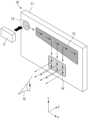
도 2는 본 발명에 따른 톱니구조의 부분반사 어레이를 갖는 증강현실 글라스의 사시도,
도 3은 도 2의 평면도,
도 4은 도 3에서 부분반사 어레이(324)가 분해된 상태의 평면도,
도 5는 도 2에 도시된 증강현실 글라스의 광학 시스템의 광학적 동작 상태도,
도 6은 도 5 중 부분반사 어레이(324)의 동작 설명도,
도 7은 투과면(324a)과 반사면(324b)의 광학적 부분 상세도,
도 8은 본 발명에 따른 기능성 편광코팅층(325)의 광학적 특성을 나타내는 그래프이다.The following drawings attached to this specification illustrate preferred embodiments of the present invention, and serve to further understand the technical idea of the present invention together with the detailed description of the invention described later. Therefore, the present invention includes the matters described in such drawings. It should not be interpreted as limited to only .
1 is a conceptual diagram of a conventional exit pupil expanded diffraction optical system;
Figure 2 is a perspective view of augmented reality glasses having a partially reflective array with a sawtooth structure according to the present invention;
Figure 3 is a plan view of Figure 2;
Figure 4 is a plan view of the partially
Figure 5 is an optical operation state diagram of the optical system of the augmented reality glasses shown in Figure 2;
FIG. 6 is a diagram illustrating the operation of the partially
7 is a detailed optical view of the
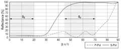
Figure 8 is a graph showing the optical characteristics of the functional
아래에서는 첨부한 도면을 참고로 하여 본 발명의 실시예에 대하여 본 발명이 속하는 기술분야에서 통상의 지식을 가진 자가 용이하게 실시할 수 있도록 상세히 설명한다. 그러나 본 발명에 관한 설명은 구조적 내지 기능적 설명을 위한 실시예에 불과하므로, 본 발명의 권리범위는 본문에 설명된 실시예에 의하여 제한되는 것으로 해석되어서는 아니 된다. 즉, 실시예는 다양한 변경이 가능하고 여러 가지 형태를 가질 수 있으므로 본 발명의 권리범위는 기술적 사상을 실현할 수 있는 균등물들을 포함하는 것으로 이해되어야 한다. 또한, 본 발명에서 제시된 목적 또는 효과는 특정 실시예가 이를 전부 포함하여야 한다거나 그러한 효과만을 포함하여야 한다는 의미는 아니므로, 본 발명의 권리범위는 이에 의하여 제한되는 것으로 이해되어서는 아니 될 것이다.Below, with reference to the attached drawings, embodiments of the present invention will be described in detail so that those skilled in the art can easily implement the present invention. However, since the description of the present invention is only an example for structural or functional explanation, the scope of the present invention should not be construed as limited by the examples described in the text. In other words, since the embodiments can be modified in various ways and can have various forms, the scope of rights of the present invention should be understood to include equivalents that can realize the technical idea. In addition, the purpose or effect presented in the present invention does not mean that a specific embodiment must include all or only such effects, so the scope of the present invention should not be understood as limited thereby.
본 발명에서 서술되는 용어의 의미는 다음과 같이 이해되어야 할 것이다.The meaning of terms described in the present invention should be understood as follows.
"제1", "제2" 등의 용어는 하나의 구성요소를 다른 구성요소로부터 구별하기 위한 것으로, 이들 용어들에 의해 권리범위가 한정되어서는 아니 된다. 예를 들어, 제1 구성요소는 제2 구성요소로 명명될 수 있고, 유사하게 제2 구성요소도 제1 구성요소로 명명될 수 있다. 어떤 구성요소가 다른 구성요소에 "연결되어" 있다고 언급된 때에는, 그 다른 구성요소에 직접적으로 연결될 수도 있지만, 중간에 다른 구성요소가 존재할 수도 있다고 이해되어야 할 것이다. 반면에, 어떤 구성요소가 다른 구성요소에 "직접 연결되어" 있다고 언급된 때에는 중간에 다른 구성요소가 존재하지 않는 것으로 이해되어야 할 것이다. 한편, 구성요소들 간의 관계를 설명하는 다른 표현들, 즉 "~사이에"와 "바로 ~사이에" 또는 "~에 이웃하는"과 "~에 직접 이웃하는" 등도 마찬가지로 해석되어야 한다.Terms such as “first” and “second” are used to distinguish one component from another component, and the scope of rights should not be limited by these terms. For example, a first component may be named a second component, and similarly, the second component may also be named a first component. When a component is referred to as being “connected” to another component, it should be understood that it may be directly connected to the other component, but that other components may also exist in between. On the other hand, when a component is referred to as being “directly connected” to another component, it should be understood that there are no other components in between. Meanwhile, other expressions that describe the relationship between components, such as "between" and "immediately between" or "neighboring" and "directly neighboring" should be interpreted similarly.
단수의 표현은 문맥상 명백하게 다르게 뜻하지 않는 한 복수의 표현을 포함하는 것으로 이해되어야 하고, "포함하다" 또는 "가지다" 등의 용어는 설시된 특징, 숫자, 단계, 동작, 구성요소, 부분품 또는 이들을 조합한 것이 존재함을 지정하려는 것이며, 하나 또는 그 이상의 다른 특징이나 숫자, 단계, 동작, 구성요소, 부분품 또는 이들을 조합한 것들의 존재 또는 부가 가능성을 미리 배제하지 않는 것으로 이해되어야 한다.Singular expressions should be understood to include plural expressions, unless the context clearly indicates otherwise, and terms such as “comprise” or “have” refer to the specified features, numbers, steps, operations, components, parts, or them. It is intended to specify the existence of a combination, and should be understood as not excluding in advance the possibility of the presence or addition of one or more other features, numbers, steps, operations, components, parts, or combinations thereof.
여기서 사용되는 모든 용어들은 다르게 정의되지 않는 한, 본 발명이 속하는 분야에서 통상의 지식을 가진 자에 의해 일반적으로 이해되는 것과 동일한 의미를 가진다. 일반적으로 사용되는 사전에 정의되어 있는 용어들은 관련 기술의 문맥상 가지는 의미와 일치하는 것으로 해석되어야 하며, 본 발명에서 명백하게 정의하지 않는 한 이상적이거나 과도하게 형식적인 의미를 지니는 것으로 해석될 수 없다.All terms used herein, unless otherwise defined, have the same meaning as commonly understood by a person of ordinary skill in the field to which the present invention pertains. Terms defined in commonly used dictionaries should be interpreted as consistent with the meaning they have in the context of the related technology, and cannot be interpreted as having an ideal or excessively formal meaning unless clearly defined in the present invention.
이하, 첨부된 도면을 참조하여 바람직한 실시예의 구성을 상세히 설명하기로 한다. 도 2는 본 발명에 따른 톱니구조의 부분반사 어레이를 갖는 증강현실 글라스의 사시도이고, 도 3은 도 2의 평면도이며, 그리고 도 4은 도 3에서 부분반사 어레이(324)가 분해된 상태의 평면도이다. 도 2 내지 도 4에 도시된 바와 같이, 본 발명은 대략 입사광학계(31), 도파로(32)로 구성된다.Hereinafter, the configuration of the preferred embodiment will be described in detail with reference to the attached drawings. FIG. 2 is a perspective view of augmented reality glass having a partially reflective array with a sawtooth structure according to the present invention, FIG. 3 is a plan view of FIG. 2, and FIG. 4 is a plan view of the partially
입사광학계(31)는 디스플레이 소자(30), 편광소자(311) 및 렌즈(312)를 포함한다. 디스플레이 패널(30)은 LCD패널, OLED패널, OLEDos패널, LCOS패널과 같은 미세 픽셀 구조를 갖는 마이크로디스플레이가 된다.The incident
편광소자(311)는 디스플레이 소자(30)와 평행하게 구비되며 S-pol 또는 P-pol의 편광성분을 선택적으로 통과시킨다. 본 실시예에서 편광소자(311)는 S-pol의 편광성분을 선택하도록 하였다. 편광소자(311)는 반사식 편광필름, 흡수식 편광필름, 무편광빔 혹은 일부 편광된 빔을 선평광된 빔으로 변환하여 투과시키거나 반사시킬 수 있는 편광코팅, 위상변위 소자를 이용해 편광성분의 방향을 전환할 수 있는 수단 중 적어도 하나가 될 수 있다.The
렌즈(312)는 편광소자(311)의 일측에 구비되고, 편광소자(311)를 투과한 영상광을 확대하고 집광하여 도파로(32) 내에서 제 1 초점(F1)을 형성할 수 있도록 한다. 이러한 렌즈(312)는 하나의 렌즈이거나 복수개의 렌즈 조합일 수 있다.The
도파로(32)는 렌즈(312)로부터 영상광이 입사되고, 입사된 영상광의 출사동을 수평방향으로 확장하여 사용자(15) 측으로 출사시키는 역할을 한다. 도파로(32)는 서로 평행한 제 1, 2 표면(322, 323)을 가지며, 일측으로 테이퍼 형태로 확대된 입사면(321)이 일체로 형성되어 있다. 입사면(321)은 제 1 표면(322)으로 소정의 입사각(θi)(예 : 50° ~ 80°)을 형성하며, 입사광학계(31)와 평행하게 위치한다.The
부분반사 어레이(324)는 도파로(32)의 중간영역부터 입사면(321)의 반대측인 자유단 영역 범위에 형성되고, 평면 방향에서는 톱니 형상을 하며, 사용자(15)가 바라보는 정면 방향에서는 수직이면서 상호 평행한 선으로 표현된다.The partially
도 3은 분할된 반사면(324b)을 이용하여 출사동을 확장하는 원리를 설명한 그림이다. 도 3을 참조하면, 도파로(32) 내 제 1 표면(322)과 제 2 표면(323) 사이에는 톱니구조의 부분반사 어레이(324)가 설치되어 있다. 톱니구조의 부분반사 어레이(324)는 영상광이 투과하는 투과면(324a)과 영상광이 반사하는 반사면(324b)들의 어레이로 구성되어 있으며, 투과면(324a)들과 반사면들은 각각 서로 평행하게 설치되어 있다.Figure 3 is a diagram explaining the principle of expanding the exit pupil using the divided
디스플레이 소자(30)에서 시준된 영상광은 입사광학계(31)에 의해 집광되어 도파로(32)내의 제 1 표면(322)에서 전반사된다. 그 후, 방향이 바뀌며, 톱니구조의 반사면(324b)에 도달하기 전에 1차 출사동(제 1 초점, F1) 영역을 형성한 후 다시 발산하는 영상광이 서로 평행하게 설치된 여러 개의 부분반사 어레이(324)에 의해 분할 반사되어 사용자(15)의 안구 전방에서 2차 출사동(제 2 초점, F2)을 형성한다.The image light collimated from the
이와 같이 1차 출사동(제 1 초점, F1)을 통과한 영상광이 부분반사 코팅된 다수의 반사면(324b)을 통해 사용자(15)의 안구 전방에서 출사동의 크기가 확장되어 형성됨으로써 사용자는 보다 넓은 영역에서 영상광을 볼 수 있으며, 이에 따라 넓은 광시야각을 용이하게 구성할 수 있다.In this way, the image light that has passed through the primary exit pupil (first focus, F1) is formed by expanding the size of the exit pupil in front of the eyeball of the
도 4에 도시된 바와 같이, 부분반사 어레이(324)는 암형 톱니부(40)와 수형 톱니부(45)의 결합으로 구현된다. 도파로(32)와 부분반사 어레이(324)는 플라스틱 사출 성형을 통해 제작할 수 있다.As shown in FIG. 4, the partially
부분반사 어레이(324)는 별도의 분리된 부품이며, 암형 톱니부(40)에 형상 맞춤될 수 있는 수형 톱니부(45)를 갖는다.The partially
암형 톱니부(40)와 수형 톱니부(45) 사이에는 영상광의 입사각 또는 영상광의 편광성분에 따라 투과 또는 반사의 정도가 달라지는 편광코팅층(325)이 더 구비된다. 편광코팅층(325)은 암형 톱니부(40) 상에 성막될 수 있고, 선택적으로 수형 톱니부(45) 상에 성막될 수도 있다. 편광 코팅층(325)은 영상광이 작은 각으로 입사되는 면에서는 투과하며 영상광이 큰 각으로 입사되는 면에서는 반사하는 각도편향성을 갖는다. 편광코팅층(325)은 S-pol 성분을 가지며, 투과각(θt)이 0° ~ 20° 범위인 경우 10% 이하의 반사율을 가지도록 구성된다.A
도파로(32)의 조립시, 부분반사 어레이(324)를 투명한 광학적 접착제로 접착하여 완성한다. 광학적 접착제는 공지의 접착제를 사용할 수 있다. 그리고, 도파로(32), 부분반사 어레이(324) 및 광학적 접착제는 동일한 굴절율을 가진 광학재료를 사용한다.When assembling the
도 5는 도 2에 도시된 증강현실 글라스의 광학 시스템의 광학적 동작 상태도이고, 도 6은 도 5 중 부분반사 어레이(324)의 동작 설명도이며, 도 7은 투과면(324a)과 반사면(324b)의 광학적 부분 상세도이다. 도 5 내지 도 7에 도시된 바와 같이, 부분반사 어레이(324)는 반사면(324b)과 투과면(324a)가 교호적으로 배치되며, 복수의 반사면(324b)은 서로 평행하거나 및/또는 복수의 투과면(324a)은 서로 평행하다.FIG. 5 is a diagram showing the optical operation of the optical system of the augmented reality glass shown in FIG. 2, FIG. 6 is a diagram illustrating the operation of the partially
투과면(324a)에서 영상광의 투과각(θt)은 반사면(324b)에서 영상광의 반사각(θr) 보다 작도록 구성한다. 예를 들어, 투과면(324a)에서 영상광의 투과각(θt)은 0°~ 20°가 되도록 투과면(324a)이 구성될 수 있고, 바람직하게는 영상광 중심광의 투과각(θt)은 0°이다.The transmission angle θt of the image light on the
반사면(324b)에서 영상광의 반사각(θr)은 45°~ 70°가 되도록 반사면(324b)이 구성된다.The
도 5는 디스플레이 소자(30)를 포함하는 입사광학계(31)의 위치와, 도파로 입사면(321)의 경사각(θi)과 도파로(32) 내에 설치된 부분반사 어레이(324)의 반사면(324b)의 경사각(θsr)과의 관계 및 투과면의 경사각(θst)과의 관계를 도시한 그림이다. 도 5를 참조하면, 디스플레이 소자(30)로부터 발산된 영상광을 얇은 구조의 도파로(32)를 이용하여 사용자(15)의 안구로 전달하기 위해서는 도파로의 입사면(321)은 영상광의 최소각과 최대각이 도파로(32) 내에서 모두 전반사될 수 있도록 일정한 경사각(θi)으로 기울어져 있어야 한다. 입사된 영상광을 사용자(15)가 동축으로 볼 수 있도록 하기 위해서는 영상광의 중심광(42)이 도파로(32)의 입사면(321)에 수직으로 입사하여야 하며, 입사된 영상광은 도파로(32)의 제 2 표면(323)에 수직으로 출사 되어야 한다. 따라서, 도파로 입사면(321)의 입사각(θi)과 도파로(32) 내에 설치된 반사면(324b)의 경사각(θsr)은 다음과 같은 (식 1)에 의해 결정된다.Figure 5 shows the position of the incident
θsr = θi / 2 (1)θsr = θi / 2 (1)
이 때, 영상광의 색수차를 최소화 하기 위해서는 영상광의 중심광(42)이 투과면(324a)을 수직으로 입사하는 것이 바람직하다. 따라서, 도파로 입사면(321)의 입사각(θi)과 도파로(32) 내에 설치된 투과면(324b)의 경사각(θst)은 다음과 같은 (식 2)에 의해 결정된다.At this time, in order to minimize the chromatic aberration of the image light, it is preferable that the
θst = 90°- θi (2)θst = 90°- θi (2)
입사면(321)의 입사각(θi)으로 입사된 영상광은 제 1 표면(322) 혹은 제 2 표면(323)에 의해 전반사된 후 톱니구조의 반사면(324b)에서 1회 반사 후 사용자(15)의 눈으로 출사된다. 이 때, 광전송 손실을 최소화하기 위해서는 도파로(32)에 입사된 영상광은 제 1 표면(322)에서 1회 반사 후 톱니구조의 반사면(324b)에서 1회 반사하여 출사된다.The image light incident at the incident angle (θi) of the
또한, 투과면 경사각(θst)은 90°- 입사각(θi) 보다 -10°~ 10° 범위의 각을 가질 수 있다.Additionally, the transmission surface inclination angle (θst) may have an angle in the range of -10° to 10° than the 90°-incident angle (θi).
도 6을 참조하면, 증강현실 기능을 가진 광학시스템을 구현하기 위해서는 도파로(32)내부로 입사된 영상광은 도파로(32)의 제 1 표면(322)에서 전반사 후 톱니구조의 부분반사 어레이(324)에 의해 사용자(15)의 눈으로 출력(R)되어야 하며, 동시에 외부 이미지는 도파로(32)를 투과(T)하여 사용자(15)의 눈으로 전달되어야 한다. 따라서 톱니구조의 투과면(324a)에서는 도파로(32)내로 입사된 영상광이 투과하여야 하며 톱니구조의 반사면(324b)에서는 영상광을 반사시켜야 한다. 이때 톱니구조는 외부 이미지가 사용자(15)의 눈으로 전달(T)되도록 투과 성능 또한 갖추고 있다.Referring to FIG. 6, in order to implement an optical system with an augmented reality function, the image light incident inside the
도 7은 투과면(324a)과 반사면(324b)의 광학적 부분 상세도이다. 도 7에 도시된 바와 같이, 최종 시야각을 형성하는 영상광은 톱니구조의 투과면(324a)에 대해 0°~ 20° 범위 이내의 작은 투과각(θt)을 가지며, 톱니구조의 반사면(324b)에대해서는 45°~ 70° 범위이내의 큰 반사각(θr)을 가진다. 이 때, 영상광의 손실을 최소화 하고, 색수차를 최소화 하기 위해서는 투과각(θt)의 중심각은 0°인 것이 바람직하다. 또한 외부시야의 투과각은 톱니구조의 경사각에 의해 결정되므로, 외부시야의 제 1 투과각(θo1)은 90°- θst로 결정된다. 그리고, 외부시야의 제 2 투과각(θo2)은 90°- θsr로 결정된다. 따라서 톱니면의 편광코팅층(325)은 작은 투과각에서는 낮은 반사율, 큰 투과각에서는 높은 반사율, 외부시야의 투과각에서는 높은 투과율 조건을 만족하는 각도편향성을 갖는다.Figure 7 is a detailed optical view of the
도 8은 본 발명에 따른 기능성 편광코팅층(325)의 광학적 특성을 나타내는 그래프이다. 도 8에 도시된 바와 같이, 편광코팅층(325)의 기능성을 만족시키기 위한 조건은 각도 편향성을 가지는 편광코팅층(325)을 통해 구현할 수 있다. 편광코팅층(325)의 S-pol 성분은 0°~ 20°이내의 작은 투과각(θt) 범위에서는 10% 이내의 낮은 반사율을 가지며, 45°~ 70° 범위를 포함하는 큰 반사각에서는 50% 이상의 높은 반사율을 가진다. 이 때, P-pol의 편광성분은 0°~ 70°의 넓은 각도 범위에서 20% 이내의 반사율을 보이므로 대부분의 빛은 투과되는 특성을 가진다. 따라서, S-pol을 가지는 영상광은 높은 반사율로 사용자의 눈을 향해 출사될 수 있으며, 동시에 P-pol 성분을 가지는 외부 이미지도 높은 투과율로 사용자(15)의 눈을 향해 투과되어 증강현실 기능을 가진 광학시스템을 구현할 수 있다.Figure 8 is a graph showing the optical characteristics of the functional
상술한 바와 같이 개시된 본 발명의 바람직한 실시예들에 대한 상세한 설명은 당업자가 본 발명을 구현하고 실시할 수 있도록 제공되었다. 상기에서는 본 발명의 바람직한 실시예들을 참조하여 설명하였지만, 해당 기술 분야의 숙련된 당업자는 본 발명의 영역으로부터 벗어나지 않는 범위 내에서 본 발명을 다양하게 수정 및 변경시킬 수 있음을 이해할 수 있을 것이다. 예를 들어, 당업자는 상술한 실시예들에 기재된 각 구성을 서로 조합하는 방식으로 이용할 수 있다. 따라서, 본 발명은 여기에 나타난 실시형태들에 제한되려는 것이 아니라, 여기서 개시된 원리들 및 신규한 특징들과 일치하는 최광의 범위를 부여하려는 것이다.A detailed description of preferred embodiments of the invention disclosed above is provided to enable any person skilled in the art to make or practice the invention. Although the present invention has been described above with reference to preferred embodiments, those skilled in the art will understand that various modifications and changes can be made to the present invention without departing from the scope of the present invention. For example, a person skilled in the art may use each configuration described in the above-described embodiments by combining them with each other. Accordingly, the present invention is not intended to be limited to the embodiments shown herein but is to be accorded the widest scope consistent with the principles and novel features disclosed herein.
본 발명은 본 발명의 정신 및 필수적 특징을 벗어나지 않는 범위에서 다른 특정한 형태로 구체화될 수 있다. 따라서, 상기의 상세한 설명은 모든 면에서 제한적으로 해석되어서는 아니 되고 예시적인 것으로 고려되어야 한다. 본 발명의 범위는 첨부된 청구항의 합리적 해석에 의해 결정되어야 하고, 본 발명의 등가적 범위 내에서의 모든 변경은 본 발명의 범위에 포함된다. 본 발명은 여기에 나타난 실시형태들에 제한되려는 것이 아니라, 여기서 개시된 원리들 및 신규한 특징들과 일치하는 최광의 범위를 부여하려는 것이다. 또한, 특허청구범위에서 명시적인 인용 관계가 있지 않은 청구항들을 결합하여 실시예를 구성하거나 출원 후의 보정에 의해 새로운 청구항으로 포함할 수 있다.The present invention may be embodied in other specific forms without departing from the spirit and essential features of the present invention. Accordingly, the above detailed description should not be construed as restrictive in all respects and should be considered illustrative. The scope of the present invention should be determined by reasonable interpretation of the appended claims, and all changes within the equivalent scope of the present invention are included in the scope of the present invention. The present invention is not intended to be limited to the embodiments shown herein but is to be accorded the widest scope consistent with the principles and novel features disclosed herein. In addition, claims that do not have an explicit reference relationship in the patent claims can be combined to form an embodiment or included as a new claim through amendment after filing.
5 : 광원출력모듈,
10 : 도광판,
11 : 광가이드부,
12 : 입력회절광학소자,
13 : 중간회절광학소자,
14 : 출력회절광학소자,
15 : 사용자,
30 : 디스플레이 패널,
31 : 입사광학계,
32 : 도파로,
37 : 가상 영상,
40 : 암형 톱니부,
41 : 제 1 광,
42 : 영상의 중심광,
43 : 제 2 광,
45 : 수형 톱니부,
311 : 편광소자,
312 : 렌즈,
321 : 입사면,
322 : 제 1 표면,
323 : 제 2 표면,
324 : 부분반사 어레이,
324a : 투과면,
324b : 반사면,
325 : 편광코팅층,
F1 : 제 1 초점,
F2 : 제 2 초점,
T, T1, T2 : 외부 이미지,
θi : 입사각,
θr : 영상광의 반사각,
θt : 영상광의 투과각,
θo1 : 제 1 투과각,
θo2 : 제 2 투과각,
θsr : 반사면의 경사각,
θst : 투과면의 경사각.5: Light source output module,
10: light guide plate,
11: Light guide part,
12: Input diffraction optical element,
13: intermediate diffraction optical element,
14: Output diffraction optical element,
15: user,
30: display panel,
31: incident optical system,
32: waveguide,
37: virtual video,
40: female toothed portion,
41: 1st light,
42: Center light of image,
43: 2nd light,
45: male toothed portion,
311: Polarizing element,
312: lens,
321: entrance surface,
322: first surface,
323: second surface,
324: Partial reflection array,
324a: transparent surface,
324b: reflective surface,
325: Polarizing coating layer,
F1: first focus,
F2: second focus,
T, T1, T2: external image,
θi: angle of incidence,
θr: Reflection angle of image light,
θt: Transmission angle of image light,
θo1: first transmission angle,
θo2: second transmission angle,
θsr: Inclination angle of the reflecting surface,
θst: Inclination angle of the transmission surface.
Claims (11)
Translated fromKorean영상광을 생성하는 디스플레이 소자(30);
상기 디스플레이 소자(30)과 평행하게 대면하고 S-pol 또는 P-pol의 편광성분을 결정하는 편광소자(311);
상기 편광소자(311)의 일측에 구비되고, 상기 편광소자(311)를 투과한 영상광을 확대하고 집광하여 도파로(32) 내에서 초점면을 형성할 수 있도록 하는 렌즈(312); 및
상기 렌즈(312)로부터 상기 영상광이 입사되고, 입사된 상기 영상광의 출사동을 수평방향으로 확장하여 사용자(15) 측으로 출사시키는 상기 도파로(32);를 포함하고,
상기 도파로(32)는,
상기 영상광이 입사되어 전반사되고, 상호 평행한 제 1 표면(322)과 제 2 표면(323);
상기 제 1 표면(322)과 소정의 입사각(θi)을 형성하는 입사면(321);
상기 제 1 표면(322)과 제 2 표면(323) 상에 구비되고, 전반사된 상기 영상광이 투과하는 투과면(324a)과 투과된 상기 영상광이 반사하는 반사면(324b)이 상호 교호적으로 구비되어 톱니 구조를 이루는 부분반사 어레이(324); 및
상기 톱니 구조 상에 성막되고, 상기 투과면(324a) 또는 상기 반사면(324b)에 입사하는 입사각에 따라 상이한 반사율을 나타내도록 각도 편향성을 갖는 편광코팅층(325);을 포함하고,
상기 투과면(324a)에서 상기 영상광의 투과각(θt)은 상기 반사면(324b)에서 상기 영상광의 반사각(θr) 보다 작으며,
상기 입사각(θi)과 상기 반사면(324b)의 경사각(θsr)은 다음의 (식 1)을 만족하며,
θsr = θi / 2 (1)
상기 입사각(θi)과 상기 투과면(324a)의 경사각(θst)은 다음의 (식 2)을 만족하는
θst = 90° - θi (2)
것을 특징으로 하는 톱니구조의 부분반사 어레이를 갖는 증강현실 글라스의 광학 시스템.In the optical system of augmented reality glasses,
A display element 30 that generates image light;
A polarizing element 311 faces the display element 30 in parallel and determines the polarization component of S-pol or P-pol;
a lens 312 provided on one side of the polarizing element 311, which magnifies and condenses the image light passing through the polarizing element 311 to form a focal plane within the waveguide 32; and
The waveguide 32 receives the image light from the lens 312, expands the exit pupil of the incident image light in the horizontal direction, and emits it toward the user 15,
The waveguide 32 is,
The image light is incident and totally reflected, and a first surface 322 and a second surface 323 are parallel to each other;
an incident surface 321 forming a predetermined incident angle θi with the first surface 322;
It is provided on the first surface 322 and the second surface 323, and a transmission surface 324a through which the totally reflected image light transmits and a reflection surface 324b through which the transmitted image light is reflected are alternating with each other. A partially reflective array 324 provided with a sawtooth structure; and
A polarizing coating layer 325 formed on the sawtooth structure and having angular deflection to exhibit different reflectance depending on the angle of incidence on the transmission surface 324a or the reflection surface 324b,
The transmission angle (θt) of the image light at the transmission surface 324a is smaller than the reflection angle (θr) of the image light at the reflection surface 324b,
The incident angle (θi) and the inclination angle (θsr) of the reflecting surface 324b satisfy the following (Equation 1),
θsr = θi / 2 (1)
The incident angle (θi) and the inclination angle (θst) of the transmission surface 324a satisfy the following (Equation 2)
θst = 90° - θi (2)
An optical system of augmented reality glass having a partially reflective array with a sawtooth structure.
상기 투과면(324a)에서 상기 영상광의 투과각(θt)은 0° ~ 20° 가 되도록 상기 투과면(324a)이 구성되는 것을 특징으로 하는 톱니구조의 부분반사 어레이를 갖는 증강현실 글라스의 광학 시스템.According to claim 1,
An optical system of augmented reality glass having a partial reflection array of a sawtooth structure, wherein the transmission surface (324a) is configured such that the transmission angle (θt) of the image light in the transmission surface (324a) is 0° to 20°. .
상기 반사면(324b)에서 상기 영상광의 반사각(θr)은 45° ~ 70° 가 되도록 상기 반사면(324b)이 구성되는 것을 특징으로 하는 톱니구조의 부분반사 어레이를 갖는 증강현실 글라스의 광학 시스템.According to claim 1,
An optical system of augmented reality glasses having a partial reflection array with a sawtooth structure, wherein the reflection angle (θr) of the image light on the reflection surface (324b) is configured to be 45° to 70°.
상기 편광코팅층(325)은 S-pol 성분을 가지며, 상기 영상광의 투과각(θt)이 0° ~ 20° 범위인 경우 10% 이하의 반사율을 가지는 것을 특징으로 하는 톱니구조의 부분반사 어레이를 갖는 증강현실 글라스의 광학 시스템.According to claim 1,
The polarizing coating layer 325 has an S-pol component and has a partial reflection array with a sawtooth structure, characterized in that it has a reflectance of 10% or less when the transmission angle (θt) of the image light is in the range of 0° to 20°. Optical system of augmented reality glasses.
상기 편광코팅층(325)은 S-pol 성분을 가지며, 상기 영상광의 반사각(θr)이 45° ~ 70° 범위인 경우 50% 이상의 반사율을 가지는 것을 특징으로 하는 톱니구조의 부분반사 어레이를 갖는 증강현실 글라스의 광학 시스템.According to claim 1,
The polarization coating layer 325 has an S-pol component, and has a reflectance of more than 50% when the reflection angle (θr) of the image light is in the range of 45° to 70°. Augmented reality with a partial reflection array of a sawtooth structure. Glass optical system.
상기 편광소자(311)는 S-pol의 편광성분을 결정하는 것을 특징으로 하는 톱니구조의 부분반사 어레이를 갖는 증강현실 글라스의 광학 시스템.According to claim 1,
The polarization element 311 is an optical system of augmented reality glass having a partial reflection array with a sawtooth structure, wherein the polarization element 311 determines the polarization component of S-pol.
복수의 상기 반사면(324b)은 서로 평행하거나 혹은 복수의 상기 투과면(324a)은 서로 평행한 것을 특징으로 하는 톱니구조의 부분반사 어레이를 갖는 증강현실 글라스의 광학 시스템.According to claim 1,
An optical system of augmented reality glasses having a partial reflection array with a sawtooth structure, wherein the plurality of reflective surfaces (324b) are parallel to each other or the plurality of transparent surfaces (324a) are parallel to each other.
상기 투과면의 경사각(θst)은 90° - 입사각(θi) 보다 -10° ~ 10° 범위의 각을 가지는 것을 특징으로 하는 톱니구조의 부분반사 어레이를 갖는 증강현실 글라스의 광학 시스템.According to claim 1,
The optical system of augmented reality glass having a partial reflection array of a sawtooth structure, characterized in that the inclination angle (θst) of the transmission surface is 90° - an angle in the range of -10° to 10° than the incident angle (θi).
상기 편광소자(311)는 반사식 편광필름, 흡수식 편광필름, 무편광빔 혹은 일부 편광된 빔을 선평광된 빔으로 변환하여 투과시키거나 반사시킬수 있는 편광코팅, 위상변위 소자를 이용해 편광성분의 방향을 전환할 수 있는 수단 중 적어도 하나인 것을 특징으로 하는 톱니구조의 부분반사 어레이를 갖는 증강현실 글라스의 광학 시스템.According to claim 1,
The polarizing element 311 uses a reflective polarizing film, an absorptive polarizing film, a polarizing coating that can convert an unpolarized beam or a partially polarized beam into a linearly polarized beam and transmit or reflect it, and a phase shift element to direct the polarization component. An optical system of augmented reality glass having a partially reflective array with a sawtooth structure, characterized in that it is at least one of the means for switching.
Priority Applications (2)
| Application Number | Priority Date | Filing Date | Title |
|---|---|---|---|
| KR1020230047991AKR102646815B1 (en) | 2023-04-12 | 2023-04-12 | Optical system of augmented reality glasses with saw tooth-type partial reflector array |
| US18/379,932US12044886B1 (en) | 2023-04-12 | 2023-10-13 | Optical system of augmented reality glasses with saw tooth-type partial reflector array |
Applications Claiming Priority (1)
| Application Number | Priority Date | Filing Date | Title |
|---|---|---|---|
| KR1020230047991AKR102646815B1 (en) | 2023-04-12 | 2023-04-12 | Optical system of augmented reality glasses with saw tooth-type partial reflector array |
Publications (1)
| Publication Number | Publication Date |
|---|---|
| KR102646815B1true KR102646815B1 (en) | 2024-03-13 |
Family
ID=90299089
Family Applications (1)
| Application Number | Title | Priority Date | Filing Date |
|---|---|---|---|
| KR1020230047991AActiveKR102646815B1 (en) | 2023-04-12 | 2023-04-12 | Optical system of augmented reality glasses with saw tooth-type partial reflector array |
Country Status (2)
| Country | Link |
|---|---|
| US (1) | US12044886B1 (en) |
| KR (1) | KR102646815B1 (en) |
Citations (7)
| Publication number | Priority date | Publication date | Assignee | Title |
|---|---|---|---|---|
| KR100637572B1 (en)* | 2004-12-14 | 2006-10-23 | (주)옵티스 | Optical pickup device including phase difference mirror |
| KR20070023622A (en)* | 2003-09-10 | 2007-02-28 | 루머스 리미티드 | Substrate-guided optical devices |
| KR100977232B1 (en) | 2002-03-21 | 2010-08-20 | 루머스 리미티드 | Optical Guide Optics |
| CN104536139A (en)* | 2015-01-25 | 2015-04-22 | 上海理湃光晶技术有限公司 | Prism coupling type wedge-shaped plane waveguide optical device |
| KR101517299B1 (en)* | 2013-11-15 | 2015-05-04 | (주)그린광학 | Glasses Type Display Device using Light Guide Plate |
| KR102201723B1 (en) | 2020-09-02 | 2021-01-12 | 주식회사 맥스트 | Optical system of head mounted display and head mounted display with the same |
| JP2021076840A (en)* | 2019-11-07 | 2021-05-20 | 中強光電股▲ふん▼有限公司 | Near-eye optical system |
Family Cites Families (8)
| Publication number | Priority date | Publication date | Assignee | Title |
|---|---|---|---|---|
| DE102007021036A1 (en)* | 2007-05-04 | 2008-11-06 | Carl Zeiss Ag | Display device and display method for binocular display of a multicolor image |
| US8384999B1 (en)* | 2012-01-09 | 2013-02-26 | Cerr Limited | Optical modules |
| US8885997B2 (en)* | 2012-08-31 | 2014-11-11 | Microsoft Corporation | NED polarization system for wavelength pass-through |
| US9513480B2 (en) | 2015-02-09 | 2016-12-06 | Microsoft Technology Licensing, Llc | Waveguide |
| DE102015122055B4 (en)* | 2015-12-17 | 2018-08-30 | Carl Zeiss Ag | Optical system and method for transmitting a source image |
| US10061124B2 (en)* | 2016-04-29 | 2018-08-28 | Microsoft Technology Licensing, Llc | Robust architecture for large field of view components |
| EP3999884A4 (en)* | 2019-07-19 | 2023-08-30 | Magic Leap, Inc. | DISPLAY DEVICE WITH DIFFRACTION GRATINGS WITH REDUCED POLARIZATION SENSITIVITY |
| US10935730B1 (en)* | 2019-11-25 | 2021-03-02 | Shanghai North Ocean Photonics Co., Ltd. | Waveguide display device |
- 2023
- 2023-04-12KRKR1020230047991Apatent/KR102646815B1/enactiveActive
- 2023-10-13USUS18/379,932patent/US12044886B1/enactiveActive
Patent Citations (7)
| Publication number | Priority date | Publication date | Assignee | Title |
|---|---|---|---|---|
| KR100977232B1 (en) | 2002-03-21 | 2010-08-20 | 루머스 리미티드 | Optical Guide Optics |
| KR20070023622A (en)* | 2003-09-10 | 2007-02-28 | 루머스 리미티드 | Substrate-guided optical devices |
| KR100637572B1 (en)* | 2004-12-14 | 2006-10-23 | (주)옵티스 | Optical pickup device including phase difference mirror |
| KR101517299B1 (en)* | 2013-11-15 | 2015-05-04 | (주)그린광학 | Glasses Type Display Device using Light Guide Plate |
| CN104536139A (en)* | 2015-01-25 | 2015-04-22 | 上海理湃光晶技术有限公司 | Prism coupling type wedge-shaped plane waveguide optical device |
| JP2021076840A (en)* | 2019-11-07 | 2021-05-20 | 中強光電股▲ふん▼有限公司 | Near-eye optical system |
| KR102201723B1 (en) | 2020-09-02 | 2021-01-12 | 주식회사 맥스트 | Optical system of head mounted display and head mounted display with the same |
Also Published As
| Publication number | Publication date |
|---|---|
| US12044886B1 (en) | 2024-07-23 |
Similar Documents
| Publication | Publication Date | Title |
|---|---|---|
| US10345598B2 (en) | Low profile image combiner for near-eye displays | |
| KR102860226B1 (en) | High-efficiency compact head-mounted display system with small input aperture | |
| US10007117B2 (en) | Imaging light guide with reflective turning array | |
| CN104614858B (en) | Saw tooth structure plane waveguide visual optical display device for enhancing reality | |
| KR102582246B1 (en) | Optical system of augment reality glasses | |
| KR102777529B1 (en) | Optical device for mitigating ghost images | |
| US20210215941A1 (en) | Imaging light guide with reflective turning array | |
| CN110515208A (en) | short distance optics | |
| KR102129669B1 (en) | Optical system of see-through head mounted display having total internal reflection element | |
| KR102687259B1 (en) | Compact optical device for augmented reality using embedded collimator and negative refractive optical element | |
| US20250155714A1 (en) | Optical device for augmented reality using polarizing optical element | |
| KR102713445B1 (en) | Compact optical device for augmented reality using negative refractive optical element | |
| CN112505920A (en) | Miniaturized short-distance optical system | |
| KR102646815B1 (en) | Optical system of augmented reality glasses with saw tooth-type partial reflector array | |
| KR102399901B1 (en) | See-through type head mounted display with optical eye-box expansion means | |
| KR102667889B1 (en) | Image display device using partial reflector array and wedge reflective prism | |
| JP2018173633A (en) | Head-mounted display device | |
| CN104597603B (en) | The visual optical display device of flat serrations sandwich | |
| KR20230127737A (en) | Optical device for augmented reality using polarizer | |
| KR102080998B1 (en) | (Optical system of see-through head mounted display having look forwarding implement of periscope manner | |
| TWI829434B (en) | Optical lens module, optical engine module and head mounted display | |
| KR102808897B1 (en) | Optical device for augmented reality having expanded eyebox using polarization | |
| US20200142211A1 (en) | Display device | |
| JP2025006920A (en) | Virtual image display device and optical unit | |
| KR20240013445A (en) | Optical device for augmented reality with expanded eyebox using diffractive optical elements |
Legal Events
| Date | Code | Title | Description |
|---|---|---|---|
| PA0109 | Patent application | St.27 status event code:A-0-1-A10-A12-nap-PA0109 | |
| PA0201 | Request for examination | St.27 status event code:A-1-2-D10-D11-exm-PA0201 | |
| R18-X000 | Changes to party contact information recorded | St.27 status event code:A-3-3-R10-R18-oth-X000 | |
| PA0302 | Request for accelerated examination | St.27 status event code:A-1-2-D10-D17-exm-PA0302 St.27 status event code:A-1-2-D10-D16-exm-PA0302 | |
| D13-X000 | Search requested | St.27 status event code:A-1-2-D10-D13-srh-X000 | |
| D14-X000 | Search report completed | St.27 status event code:A-1-2-D10-D14-srh-X000 | |
| PE0902 | Notice of grounds for rejection | St.27 status event code:A-1-2-D10-D21-exm-PE0902 | |
| E13-X000 | Pre-grant limitation requested | St.27 status event code:A-2-3-E10-E13-lim-X000 | |
| P11-X000 | Amendment of application requested | St.27 status event code:A-2-2-P10-P11-nap-X000 | |
| P13-X000 | Application amended | St.27 status event code:A-2-2-P10-P13-nap-X000 | |
| PE0902 | Notice of grounds for rejection | St.27 status event code:A-1-2-D10-D21-exm-PE0902 | |
| P11-X000 | Amendment of application requested | St.27 status event code:A-2-2-P10-P11-nap-X000 | |
| P13-X000 | Application amended | St.27 status event code:A-2-2-P10-P13-nap-X000 | |
| E701 | Decision to grant or registration of patent right | ||
| PE0701 | Decision of registration | St.27 status event code:A-1-2-D10-D22-exm-PE0701 | |
| GRNT | Written decision to grant | ||
| PR0701 | Registration of establishment | St.27 status event code:A-2-4-F10-F11-exm-PR0701 | |
| PR1002 | Payment of registration fee | St.27 status event code:A-2-2-U10-U11-oth-PR1002 Fee payment year number:1 | |
| PG1601 | Publication of registration | St.27 status event code:A-4-4-Q10-Q13-nap-PG1601 | |
| PN2301 | Change of applicant | St.27 status event code:A-5-5-R10-R11-asn-PN2301 | |
| PN2301 | Change of applicant | St.27 status event code:A-5-5-R10-R14-asn-PN2301 | |
| PN2301 | Change of applicant | St.27 status event code:A-5-5-R10-R11-asn-PN2301 | |
| PN2301 | Change of applicant | St.27 status event code:A-5-5-R10-R14-asn-PN2301 |