KR102645839B1 - Camera module including liquid lens - Google Patents
Camera module including liquid lensDownload PDFInfo
- Publication number
- KR102645839B1 KR102645839B1KR1020180164475AKR20180164475AKR102645839B1KR 102645839 B1KR102645839 B1KR 102645839B1KR 1020180164475 AKR1020180164475 AKR 1020180164475AKR 20180164475 AKR20180164475 AKR 20180164475AKR 102645839 B1KR102645839 B1KR 102645839B1
- Authority
- KR
- South Korea
- Prior art keywords
- temperature detection
- liquid lens
- detection element
- temperature
- camera module
- Prior art date
- Legal status (The legal status is an assumption and is not a legal conclusion. Google has not performed a legal analysis and makes no representation as to the accuracy of the status listed.)
- Active
Links
- 239000007788liquidSubstances0.000titleclaimsabstractdescription172
- 238000001514detection methodMethods0.000claimsabstractdescription200
- 238000005259measurementMethods0.000claimsdescription5
- 238000000034methodMethods0.000claimsdescription3
- 230000003287optical effectEffects0.000description37
- 239000000758substrateSubstances0.000description25
- 230000006870functionEffects0.000description13
- 230000000052comparative effectEffects0.000description12
- 238000010586diagramMethods0.000description9
- 239000000463materialSubstances0.000description4
- 230000035939shockEffects0.000description4
- 239000007787solidSubstances0.000description4
- 230000006641stabilisationEffects0.000description4
- 238000011105stabilizationMethods0.000description4
- 238000013461designMethods0.000description3
- 230000000694effectsEffects0.000description3
- 239000011521glassSubstances0.000description3
- 238000004519manufacturing processMethods0.000description3
- 239000002184metalSubstances0.000description3
- 125000006850spacer groupChemical group0.000description3
- 230000000903blocking effectEffects0.000description2
- 239000003990capacitorSubstances0.000description2
- 238000004891communicationMethods0.000description2
- 239000004020conductorSubstances0.000description2
- 230000007423decreaseEffects0.000description2
- 238000005516engineering processMethods0.000description2
- 238000012545processingMethods0.000description2
- 239000004593EpoxySubstances0.000description1
- 101100522111Oryza sativa subsp. japonica PHT1-11 geneProteins0.000description1
- WYTGDNHDOZPMIW-RCBQFDQVSA-NalstonineNatural productsC1=CC2=C3C=CC=CC3=NC2=C2N1C[C@H]1[C@H](C)OC=C(C(=O)OC)[C@H]1C2WYTGDNHDOZPMIW-RCBQFDQVSA-N0.000description1
- 230000000712assemblyEffects0.000description1
- 238000000429assemblyMethods0.000description1
- 239000006059cover glassSubstances0.000description1
- -1for exampleSubstances0.000description1
- 238000003384imaging methodMethods0.000description1
- 239000012535impuritySubstances0.000description1
- 239000011810insulating materialSubstances0.000description1
- 239000000203mixtureSubstances0.000description1
- 230000001151other effectEffects0.000description1
- 230000002093peripheral effectEffects0.000description1
- 125000001997phenyl groupChemical group[H]C1=C([H])C([H])=C(*)C([H])=C1[H]0.000description1
- 238000011160researchMethods0.000description1
- 230000004044responseEffects0.000description1
- 229920002545silicone oilPolymers0.000description1
- 239000003381stabilizerSubstances0.000description1
- 239000000126substanceSubstances0.000description1
- 230000002194synthesizing effectEffects0.000description1
- 239000012780transparent materialSubstances0.000description1
Images


Classifications
- G—PHYSICS
- G02—OPTICS
- G02B—OPTICAL ELEMENTS, SYSTEMS OR APPARATUS
- G02B7/00—Mountings, adjusting means, or light-tight connections, for optical elements
- G02B7/02—Mountings, adjusting means, or light-tight connections, for optical elements for lenses
- G02B7/028—Mountings, adjusting means, or light-tight connections, for optical elements for lenses with means for compensating for changes in temperature or for controlling the temperature; thermal stabilisation
- H—ELECTRICITY
- H04—ELECTRIC COMMUNICATION TECHNIQUE
- H04N—PICTORIAL COMMUNICATION, e.g. TELEVISION
- H04N23/00—Cameras or camera modules comprising electronic image sensors; Control thereof
- H04N23/50—Constructional details
- H04N23/55—Optical parts specially adapted for electronic image sensors; Mounting thereof
- G—PHYSICS
- G02—OPTICS
- G02B—OPTICAL ELEMENTS, SYSTEMS OR APPARATUS
- G02B3/00—Simple or compound lenses
- G02B3/12—Fluid-filled or evacuated lenses
- G—PHYSICS
- G02—OPTICS
- G02B—OPTICAL ELEMENTS, SYSTEMS OR APPARATUS
- G02B3/00—Simple or compound lenses
- G02B3/12—Fluid-filled or evacuated lenses
- G02B3/14—Fluid-filled or evacuated lenses of variable focal length
- G—PHYSICS
- G02—OPTICS
- G02B—OPTICAL ELEMENTS, SYSTEMS OR APPARATUS
- G02B7/00—Mountings, adjusting means, or light-tight connections, for optical elements
- G02B7/008—Mountings, adjusting means, or light-tight connections, for optical elements with means for compensating for changes in temperature or for controlling the temperature; thermal stabilisation
- H—ELECTRICITY
- H04—ELECTRIC COMMUNICATION TECHNIQUE
- H04N—PICTORIAL COMMUNICATION, e.g. TELEVISION
- H04N23/00—Cameras or camera modules comprising electronic image sensors; Control thereof
- H04N23/50—Constructional details
- H04N23/54—Mounting of pick-up tubes, electronic image sensors, deviation or focusing coils
- H—ELECTRICITY
- H04—ELECTRIC COMMUNICATION TECHNIQUE
- H04N—PICTORIAL COMMUNICATION, e.g. TELEVISION
- H04N23/00—Cameras or camera modules comprising electronic image sensors; Control thereof
- H04N23/57—Mechanical or electrical details of cameras or camera modules specially adapted for being embedded in other devices
- G—PHYSICS
- G02—OPTICS
- G02B—OPTICAL ELEMENTS, SYSTEMS OR APPARATUS
- G02B27/00—Optical systems or apparatus not provided for by any of the groups G02B1/00 - G02B26/00, G02B30/00
- G02B27/64—Imaging systems using optical elements for stabilisation of the lateral and angular position of the image
- G02B27/646—Imaging systems using optical elements for stabilisation of the lateral and angular position of the image compensating for small deviations, e.g. due to vibration or shake
- G—PHYSICS
- G02—OPTICS
- G02B—OPTICAL ELEMENTS, SYSTEMS OR APPARATUS
- G02B7/00—Mountings, adjusting means, or light-tight connections, for optical elements
- G02B7/003—Alignment of optical elements
Landscapes
- Physics & Mathematics (AREA)
- General Physics & Mathematics (AREA)
- Optics & Photonics (AREA)
- Engineering & Computer Science (AREA)
- Multimedia (AREA)
- Signal Processing (AREA)
- Studio Devices (AREA)
- Automatic Focus Adjustment (AREA)
- Mechanical Light Control Or Optical Switches (AREA)
Abstract
Translated fromKoreanDescription
Translated fromKorean실시 예는 액체 렌즈를 포함하는 카메라 모듈에 관한 것이다.Embodiments relate to a camera module including a liquid lens.
휴대용 장치의 사용자는 고해상도를 가지며 크기가 작고 다양한 촬영 기능을 갖는 광학 기기를 원하고 있다. 예를 들어, 다양한 촬영 기능이란, 광학 줌 기능(zoom-in/zoom-out), 오토 포커싱(AF:Auto-Focusing) 기능 또는 손떨림 보정 내지 영상 흔들림 방지(OIS:Optical Image Stabilizer) 기능 중 적어도 하나를 의미할 수 있다.Users of portable devices are demanding optical devices that have high resolution, are small in size, and have a variety of imaging functions. For example, various shooting functions include at least one of an optical zoom function (zoom-in/zoom-out), an auto-focusing (AF) function, or an image stabilization or image stabilization (OIS: Optical Image Stabilizer) function. It can mean.
기존의 경우, 전술한 다양한 촬영 기능을 구현하기 위해, 여러 개의 렌즈를 조합하고, 조합된 렌즈를 직접 움직이는 방법을 이용하였다. 그러나, 이와 같이 렌즈의 수를 증가시킬 경우 광학 기기의 크기가 커질 수 있다.In the existing case, in order to implement the various shooting functions described above, a method of combining several lenses and directly moving the combined lenses was used. However, if the number of lenses is increased in this way, the size of the optical device may increase.
오토 포커스와 손떨림 보정 기능은, 렌즈 홀더에 고정되며 광축으로 정렬된 여러 개의 렌즈가, 광축 또는 광축의 수직 방향으로 이동하거나 틸팅(Tilting)하여 수행되며, 이를 위해, 복수의 렌즈로 구성된 렌즈 어셈블리를 구동시키는 별도의 렌즈 구동 장치가 요구된다. 그러나 렌즈 구동 장치는 전력 소모가 높으며, 이를 보호하기 위해서 카메라 모듈과 별도로 커버 글라스를 추가하여야 하는 등, 기존의 카메라 모듈의 전체 크기가 커지는 문제가 있다. 이를 해소하기 위해, 두 가지 액체의 계면의 곡률과 틸팅을 전기적으로 조절하여 오토 포커스와 손떨림 보정 기능을 수행 가능한 액체 렌즈에 대한 연구가 이루어지고 있다.The autofocus and image stabilization functions are performed by moving or tilting several lenses fixed to the lens holder and aligned with the optical axis in the optical axis or the direction perpendicular to the optical axis. For this purpose, a lens assembly composed of a plurality of lenses is used. A separate lens driving device is required. However, the lens driving device consumes high power, and in order to protect it, a cover glass must be added separately from the camera module, which increases the overall size of the existing camera module. To solve this problem, research is being conducted on a liquid lens that can perform autofocus and image stabilization functions by electrically controlling the curvature and tilting of the interface between two liquids.
실시 예는 액체 렌즈의 온도를 감지할 수 있는 액체 렌즈를 포함하는 카메라 모듈을 제공하기 위한 것이다.The embodiment is intended to provide a camera module including a liquid lens that can detect the temperature of the liquid lens.
실시 예에서 해결하고자 하는 기술적 과제는 이상에서 언급한 기술적 과제로 제한되지 않으며, 언급하지 않은 또 다른 기술적 과제는 아래의 기재로부터 본 발명이 속하는 기술 분야에서 통상의 지식을 가진 자에게 명확하게 이해될 수 있을 것이다.The technical problems to be solved in the embodiments are not limited to the technical problems mentioned above, and other technical problems not mentioned will be clearly understood by those skilled in the art from the description below. You will be able to.
실시 예에 의한 카메라 모듈은, 제1 플레이트; 및 상기 제1 플레이트의 제1 면 상에 배치된 개별 전극을 포함하는 액체 렌즈; 상기 제1 플레이트의 상기 제1 면 상에서 상기 개별 전극과 이격되어 배치되는 복수의 온도검출소자; 및 상기 복수의 온도검출소자와 연결되어 상기 액체 렌즈의 온도를 감지하는 온도 감지부를 포함하고, 상기 복수의 온도검출소자는 서로 이격되어 배치되는 제1 및 제2 온도검출소자를 포함하고, 상기 온도 감지부는 상기 제1 온도검출소자의 일단과 연결되고, 상기 제1 온도검출소자의 타단은 상기 제2 온도검출소자의 일단과 연결되고, 상기 제2 온도검출소자의 타단은 기준 전위와 연결될 수 있다.A camera module according to an embodiment includes: a first plate; and a liquid lens including individual electrodes disposed on a first side of the first plate; a plurality of temperature detection elements arranged to be spaced apart from the individual electrodes on the first surface of the first plate; and a temperature detection unit connected to the plurality of temperature detection elements to detect the temperature of the liquid lens, wherein the plurality of temperature detection elements include first and second temperature detection elements arranged to be spaced apart from each other, and the temperature detection element is connected to the plurality of temperature detection elements. The sensing unit may be connected to one end of the first temperature detection element, the other end of the first temperature detection element may be connected to one end of the second temperature detection element, and the other end of the second temperature detection element may be connected to a reference potential. .
예를 들어, 상기 카메라 모듈은 상기 개별전극과 연결된 연결 기판; 이미지 센서; 및 상기 이미지 센서가 실장된 메인 기판을 포함하고, 상기 온도 감지부는 상기 메인 기판에 배치될 수 있다.For example, the camera module may include a connection board connected to the individual electrodes; image sensor; and a main board on which the image sensor is mounted, and the temperature sensor may be disposed on the main board.
예를 들어, 상기 제1 온도검출소자의 상기 타단과 상기 제2 온도검출소자의 상기 일단은 상기 메인 기판을 통해 연결될 수 있다.For example, the other end of the first temperature detection element and the one end of the second temperature detection element may be connected through the main board.
예를 들어, 상기 제1 온도검출소자의 상기 일단과 상기 타단은 상기 액체 렌즈의 제1 에지영역에 배치되고, 상기 제2 온도검출소자의 상기 일단과 상기 타단은 상기 액체 렌즈의 상기 제1 에지영역의 반대측 제2 에지영역에 배치될 수 있다.For example, the one end and the other end of the first temperature detection element are disposed at the first edge area of the liquid lens, and the one end and the other end of the second temperature detection element are disposed at the first edge of the liquid lens. It may be placed in the second edge area on the opposite side of the area.
예를 들어, 상기 제1 온도검출소자와 상기 제2 온도검출소자는 상기 액체렌즈의 중심을 사이에 두고 서로 대향하여 배치될 수 있다.For example, the first temperature detection element and the second temperature detection element may be arranged to face each other with the center of the liquid lens in between.
예를 들어, 상기 제1 및 제2 온도검출소자의 저항값은 서로 동일할 수 있다.For example, the resistance values of the first and second temperature detection elements may be the same.
예를 들어, 상기 온도 감지부는 상기 제1 온도검출소자의 상기 일단에 구동 신호를 공급하는 감지 구동부; 및 상기 제1 온도검출소자의 상기 일단에 연결되어 상기 복수의 온도검출소자의 온도 정보를 측정하는 온도 정보 측정부를 포함할 수 있다.For example, the temperature sensing unit may include a sensing driver that supplies a driving signal to the one end of the first temperature sensing element; and a temperature information measurement unit connected to the one end of the first temperature detection element and measuring temperature information of the plurality of temperature detection elements.
실시 예에 따른 액체 렌즈를 포함하는 카메라 모듈은 제1 및 제2 온도 검출 소자를 액체 렌즈의 양측에 배치하므로, 온도 검출 소자의 라인간 길이를 길게 구현할 필요도 없고, 라인 간 간격이 넓을 수 있어, 열에 의해 온도 검출 소자의 라인이 변형될 염려가 적고, 구조적 설계가 단순화되고, 제조 공정이 용이해질 수 있다.A camera module including a liquid lens according to an embodiment places the first and second temperature detection elements on both sides of the liquid lens, so there is no need to implement a long length between the lines of the temperature detection elements, and the gap between the lines can be wide. , there is less concern that the line of the temperature detection element will be deformed by heat, the structural design can be simplified, and the manufacturing process can be facilitated.
또한, 실시 예에 따른 액체 렌즈를 포함하는 카메라 모듈에서, 제1 플레이트의 상면과 하면 중에서 보다 더 넓은 면 위에 온도 검출 소자를 배치하기 때문에, 온도 검출 소자를 배치하기 위해 액체 렌즈의 면적을 키울 필요도 없고 온도 검출 소자와 공통 전극이 서로 단락될 염려도 없어 우수한 전기적 특성을 가질 수 있다.In addition, in the camera module including the liquid lens according to the embodiment, the temperature detection element is placed on a wider surface of the upper and lower surfaces of the first plate, so it is necessary to increase the area of the liquid lens to place the temperature detection element. There is no need to worry about the temperature detection element and the common electrode short-circuiting each other, so it can have excellent electrical characteristics.
또한, 실시 예에 따른 액체 렌즈를 포함하는 카메라 모듈은 복수 개의 온도 검출 소자를 가지므로 온도 검출 소자의 동작에 필요한 저항값 및 변화량을 조정함에 있어서 제한을 덜 받을 수 있다.Additionally, since the camera module including the liquid lens according to the embodiment has a plurality of temperature detection elements, there may be less restrictions in adjusting the resistance value and change amount required for the operation of the temperature detection element.
또한, 본 실시 예에서 얻을 수 있는 효과는 이상에서 언급한 효과들로 제한되지 않으며 언급하지 않은 또 다른 효과는 아래의 기재로부터 본 발명이 속하는 분야에서 통상의 지식을 가진 자에게 명확하게 이해될 수 있을 것이다.In addition, the effects that can be obtained in this embodiment are not limited to the effects mentioned above, and other effects not mentioned can be clearly understood by those skilled in the art from the description below. There will be.
도 1은 실시 예에 의한 카메라 모듈의 개략적인 블럭도를 나타낸다.
도 2는 도 1에 도시된 액체 렌즈 및 온도 검출 소자의 일 실시 예에 의한 사시도를 나타낸다.
도 3은 도 2에 도시된 I-I’선을 절취한 단면도를 나타낸다.
도 4는 도 2에 도시된 액체 렌즈의 등가회로를 나타낸다.
도 5는 도 1에 도시된 온도 검출 소자의 일 실시 예의 평면 형상을 설명하기 위한 도면이다.
도 6은 도 1에 도시된 온도 검출 소자의 다른 실시 예의 평면 형상을 설명하기 위한 도면이다.
도 7은 실시 예에 의한 액체 렌즈 모듈의 사시도를 나타낸다.
도 8은 도 1에 도시된 카메라 모듈의 동작을 설명하기 위한 도면이다.
도 9는 구동 신호가 전류 형태로 공급될 때, 도 8에 도시된 카메라 모듈의 등가 회로를 나타낸다.
도 10은 구동 신호가 전압 형태로 공급될 때, 도 8에 도시된 카메라 모듈의 등가 회로를 나타낸다.
도 11은 도 1에 도시된 카메라 모듈의 일 실시 예에 의한 분해 사시도를 나타낸다.
도 12는 도 11에 도시된 홀더와 액체 렌즈 모듈을 설명하기 위한 도면이다.
도 13은 비교 례에 의한 카메라 모듈의 국부적인 평면도를 나타낸다.1 shows a schematic block diagram of a camera module according to an embodiment.
FIG. 2 shows a perspective view of an embodiment of the liquid lens and temperature detection element shown in FIG. 1.
Figure 3 shows a cross-sectional view taken along line II' shown in Figure 2.
FIG. 4 shows an equivalent circuit of the liquid lens shown in FIG. 2.
FIG. 5 is a diagram for explaining the planar shape of an embodiment of the temperature detection element shown in FIG. 1.
FIG. 6 is a diagram for explaining the plan shape of another embodiment of the temperature detection element shown in FIG. 1.
Figure 7 shows a perspective view of a liquid lens module according to an embodiment.
FIG. 8 is a diagram for explaining the operation of the camera module shown in FIG. 1.
FIG. 9 shows the equivalent circuit of the camera module shown in FIG. 8 when the driving signal is supplied in the form of current.
FIG. 10 shows the equivalent circuit of the camera module shown in FIG. 8 when the driving signal is supplied in the form of voltage.
Figure 11 shows an exploded perspective view of an embodiment of the camera module shown in Figure 1.
FIG. 12 is a diagram for explaining the holder and liquid lens module shown in FIG. 11.
Figure 13 shows a local plan view of the camera module according to a comparative example.
이하, 첨부된 도면을 참조하여 본 발명의 바람직한 실시 예를 상세히 설명한다.Hereinafter, preferred embodiments of the present invention will be described in detail with reference to the attached drawings.
다만, 본 발명의 기술 사상은 설명되는 일부 실시 예에 한정되는 것이 아니라 서로 다른 다양한 형태로 구현될 수 있고, 본 발명의 기술 사상 범위 내에서라면, 실시 예들 간 그 구성 요소들 중 하나 이상을 선택적으로 결합, 치환하여 사용할 수 있다.However, the technical idea of the present invention is not limited to some of the described embodiments, but may be implemented in various different forms, and as long as it is within the scope of the technical idea of the present invention, one or more of the components may be optionally used between the embodiments. It can be used by combining and replacing.
또한, 본 발명의 실시 예에서 사용되는 용어(기술 및 과학적 용어를 포함)는, 명백하게 특별히 정의되어 기술되지 않는 한, 본 발명이 속하는 기술분야에서 통상의 지식을 가진 자에게 일반적으로 이해될 수 있는 의미로 해석될 수 있으며, 사전에 정의된 용어와 같이 일반적으로 사용되는 용어들은 관련 기술의 문맥상의 의미를 고려하여 그 의미를 해석할 수 있을 것이다.In addition, terms (including technical and scientific terms) used in the embodiments of the present invention, unless specifically defined and described, are generally understood by those skilled in the art to which the present invention pertains. It can be interpreted as meaning, and the meaning of commonly used terms, such as terms defined in a dictionary, can be interpreted by considering the contextual meaning of the related technology.
또한, 본 발명의 실시 예에서 사용된 용어는 실시 예들을 설명하기 위한 것이며 본 발명을 제한하고자 하는 것은 아니다. 본 명세서에서, 단수형은 문구에서 특별히 언급하지 않는 한 복수형도 포함할 수 있고, “A 및(와) B, C중 적어도 하나(또는 한 개이상)”으로 기재되는 경우 A, B, C로 조합할 수 있는 모든 조합 중 하나이상을 포함할 수 있다.Additionally, the terms used in the embodiments of the present invention are for describing the embodiments and are not intended to limit the present invention. In this specification, the singular may also include the plural unless specifically stated in the phrase, and when described as “at least one (or more than one) of A, B, and C”, it is combined with A, B, and C. It can contain one or more of all possible combinations.
또한, 본 발명의 실시 예의 구성 요소를 설명하는 데 있어서, 제1, 제2, A, B, (a), (b) 등의 용어를 사용할 수 있다. 이러한 용어는 그 구성 요소를 다른 구성 요소와 구별하기 위한 것일 뿐, 그 용어에 의해 해당 구성 요소의 본질이나 차례 또는 순서 등으로 한정되지 않는다.Additionally, when describing the components of an embodiment of the present invention, terms such as first, second, A, B, (a), and (b) may be used. These terms are only used to distinguish the component from other components, and are not limited to the essence, sequence, or order of the component.
그리고, 어떤 구성 요소가 다른 구성요소에 ‘연결’, ‘결합’ 또는 ‘접속’된다고 기재된 경우, 그 구성 요소는 그 다른 구성요소에 직접적으로 연결, 결합 또는 접속되는 경우 뿐만아니라, 그 구성 요소와 그 다른 구성요소 사이에 있는 또 다른 구성 요소로 인해 ‘연결’, ‘결합’ 또는 ‘접속’되는 경우도 포함할 수 있다.And, when a component is described as being 'connected', 'coupled' or 'connected' to another component, the component is not only directly connected, combined or connected to that other component, but also is connected to that component. It may also include cases where other components are 'connected', 'coupled', or 'connected' by another component between them.
또한, 각 구성 요소의 “상(위) 또는 하(아래)”에 형성 또는 배치되는 것으로 기재되는 경우, 상(위) 또는 하(아래)는 두 개의 구성 요소들이 서로 직접 접촉되는 경우 뿐만아니라 하나 이상의 또 다른 구성 요소가 두 개의 구성 요소들 사이에 형성 또는 배치되는 경우도 포함한다. 또한 “상(위) 또는 하(아래)”로 표현되는 경우 하나의 구성 요소를 기준으로 위쪽 방향뿐만 아니라 아래쪽 방향의 의미도 포함할 수 있다.Additionally, when described as being formed or arranged “above” or “below” each component, “above” or “below” refers not only to cases where two components are in direct contact with each other, but also to one This also includes cases where another component described above is formed or placed between two components. In addition, when expressed as “up (above) or down (down),” it can include not only the upward direction but also the downward direction based on one component.
이하, 실시 예에 의한 액체 렌즈를 포함하는 카메라 모듈(1000, 1000A)을 첨부된 도면을 참조하여 다음과 같이 설명한다. 편의상, 데카르트 좌표계(x축, y축, z축)를 이용하여 카메라 모듈(1000, 1000A)을 설명하지만, 다른 좌표계에 의해서도 이를 설명할 수 있음은 물론이다. 또한, 데카르트 좌표계에 의하면, x축, y축 및 z축은 서로 직교하지만, 실시 예는 이에 국한되지 않는다. 즉, x축, y축 및 z축은 서로 교차할 수도 있다.Hereinafter,
도 1은 실시 예에 의한 카메라 모듈(1000)의 개략적인 블럭도를 나타낸다. 여기서, LX는 광축(Optical axis)을 의미한다.Figure 1 shows a schematic block diagram of a
도 1에 도시된 카메라 모듈(1000)은 액체 렌즈(110), 온도 검출 소자(120) 및 온도 감지부(210)를 포함할 수 있다.The
도 1에서 온도 검출 소자(120)가 렌즈 어셈블리(100)에 속하는 것으로 예시되어 있지만, 실시 예는 이에 국한되지 않는다. 즉, 도 1에 도시된 바와 달리, 온도 검출 소자(120)는 렌즈 어셈블리(100)의 구성 요소가 아니라, 카메라 모듈(1000)의 구성 요소일 수도 있다. 또한, 실시 예는 액체 렌즈(110)가 포함되는 렌즈 어셈블리(100)의 특정한 구성에 국한되지 않는다. 렌즈 어셈블리(100)의 일 례에 대해서는 도 11을 참조하여 후술된다.Although the
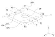
도 2는 도 1에 도시된 액체 렌즈(110) 및 온도 검출 소자(120)의 일 실시 예(110A, 120A)에 의한 사시도를 나타낸다.FIG. 2 shows a perspective view of one embodiment (110A, 120A) of the
도 3은 도 2에 도시된 I-I’선을 절취한 단면도를 나타낸다.Figure 3 shows a cross-sectional view taken along line II' shown in Figure 2.
이하에서 설명되는 도 2 및 도 3에 도시된 액체 렌즈(110A) 및 온도 검출 소자(120A)는 도 1에 도시된 액체 렌즈(110) 및 온도 검출 소자(120)의 이해를 돕기 위한 일 례에 불과하다. 즉, 도 1에 도시된 액체 렌즈(110) 및 온도 검출 소자(120)는 도 2 및 도 3에 도시된 바와 다른 다양한 형상을 가질 수 있다.The
도 2 및 도 3에 도시된 액체 렌즈(110A)는 서로 다른 종류의 복수의 액체(LQ1, LQ2), 제1 내지 제3 플레이트(P1, P2, P3), 제1 및 제2 전극(E1, E2) 및 절연층(116)을 포함할 수 있다.The
액체 렌즈(110A)는 캐비티(CA:cavity)를 포함할 수 있다. 복수의 액체(LQ1, LQ2)는 캐비티(CA)에 수용되며, 전도성을 갖는 제1 액체(LQ1)와 비전도성을 갖는 제2 액체(또는, 절연 액체)(LQ2)를 포함할 수 있다. 제1 액체(LQ1)와 제2 액체(LQ2)는 서로 섞이지 않으며, 제1 및 제2 액체(LQ1, LQ2) 사이의 접하는 부분에 계면(BO)이 형성될 수 있다. 예를 들어, 제1 액체(LQ1) 위에 제2 액체(LQ2)가 배치될 수 있으나, 실시 예는 이에 국한되지 않는다.The
또한, 액체 렌즈(110A)의 단면 형상에서 제1 및 제2 액체(LQ2, LQ1)의 가장 자리는 중심부보다 두께가 얇을 수 있다.Additionally, in the cross-sectional shape of the
제1 액체(LQ1)는 전도성을 갖는 물질일 수 있고, 제2 액체(LQ2)는 절연성을 갖는 물질일 수 있으며 예를 들면 페닐(phenyl) 계열의 실리콘 오일일 수 있다.The first liquid (LQ1) may be a conductive material, and the second liquid (LQ2) may be an insulating material, for example, phenyl-based silicone oil.
제1 플레이트(P1)의 내측면은 캐비티(CA)의 측벽(i)을 이룰 수 있다. 제1 플레이트(P1)는 기 설정된 경사면을 갖는 상하의 개구부를 포함할 수 있다. 즉, 캐비티(CA)는 제1 플레이트(P1)의 내측의 관통 홀 영역일 수 있다.The inner surface of the first plate (P1) may form the side wall (i) of the cavity (CA). The first plate P1 may include upper and lower openings with preset inclined surfaces. That is, the cavity CA may be a through-hole area inside the first plate P1.
도 3에 도시된 바와 같이 캐비티(CA)에서 광이 입사되는 방향의 제1 개구의 면적은 반대 방향의 제2 개구의 면적보다 좁을 수 있다. 또는, 캐비티(CA)의 경사 방향이 반대가 되도록 액체 렌즈(110A)가 배치될 수도 있다. 즉, 도 3에 도시된 바와 달리 캐비티(CA)에서 광이 입사되는 방향의 제2 개구의 면적이 반대 방향의 제1 개구 면적보다 클 수도 있다. 또한, 캐비티(CA)의 경사 방향이 반대가 되도록 액체 렌즈(110A)가 배치될 때, 액체 렌즈(110A)의 경사 방향에 따라서 액체 렌즈(110A)에 포함된 구성의 배치 전체 또는 일부가 함께 바뀌거나, 캐비티(CA)의 경사 방향만 변경되고 나머지 구성의 배치는 바뀌지 않을 수도 있다.As shown in FIG. 3, the area of the first opening in the cavity CA in the direction in which light is incident may be narrower than the area of the second opening in the opposite direction. Alternatively, the
제1 및 제2 개구 중에서 보다 넓은 개구의 직경은 액체 렌즈(110A)에서 요구하는 화각(FOV) 또는 액체 렌즈(110A)가 카메라 모듈(1000)에서 수행해야 할 역할에 따라 달라질 수 있다. 실시 예에 의하면, 제1 개구의 크기(또는, 면적, 또는 폭)(O1)보다 제2 개구의 크기(또는, 면적, 또는 폭)(O2)가 더 클 수 있다. 여기서, 제1 및 제2 개구들 각각의 크기는 수평 방향(예를 들어, x축과 y축 방향)의 단면적일 수 있다. 예를 들어, 제1 및 제2 개구 각각의 크기란, 개구의 단면이 원형이면 반지름을 의미하고, 개구의 단면이 정사각형이면 대각선의 길이를 의미할 수 있다.The diameter of the wider opening among the first and second openings may vary depending on the angle of view (FOV) required by the
제1 및 제2 개구 각각은 원형의 단면을 가지는 홀(hole)의 형상일 수 있으며, 두 액체가 형성한 계면(BO)은 구동 전압에 의해 캐비티(CA)의 경사면을 따라 움직일 수 있다.Each of the first and second openings may be in the shape of a hole with a circular cross-section, and the interface BO formed by the two liquids may move along the inclined surface of the cavity CA by the driving voltage.
제1 플레이트(P1)의 캐비티(CA)에 제1 액체(LQ1) 및 제2 액체(LQ2)가 충진, 수용 또는 배치된다. 또한, 캐비티(CA)는 액체 렌즈(110A)로 입사되는 광이 투과하는 부위이다. 따라서, 제1 플레이트(P1)는 투명한 재료로 이루어질 수도 있고, 광의 투과가 용이하지 않도록 불순물을 포함할 수도 있다.The first liquid (LQ1) and the second liquid (LQ2) are filled, accommodated, or disposed in the cavity (CA) of the first plate (P1). Additionally, the cavity CA is a portion through which light incident on the
복수의 제1 전극(E1)은 제2 전극(E2)과 이격되어 배치되고, 제1 플레이트(P1)의 제1 면(SF1)(즉, 상부면)과 측면과 하부면에 각각 배치될 수 있다. 제2 전극(E2)은 제1 플레이트(P1)의 제2 면(SF2)(즉, 하부면)의 적어도 일부 영역에 배치되고, 제1 액체(LQ1)와 직접 접촉할 수 있다.The plurality of first electrodes E1 are disposed to be spaced apart from the second electrode E2 and may be disposed on the first surface SF1 (i.e., top surface), side surface, and bottom surface of the first plate P1, respectively. there is. The second electrode E2 is disposed on at least a portion of the second surface SF2 (ie, the lower surface) of the first plate P1 and may be in direct contact with the first liquid LQ1.
도 3을 참조하면, 제1 및 제2 개구가 형성되기 이전에 제1 플레이트(P1)의 탑의 면적과 버텀의 면적이 동일하다면, 전술한 바와 같이 제1 개구가 제2 개구보다 면적이 작으므로 제1 플레이트(P1)에서 제1 개구 주위의 제1 면(SF1)의 면적이 제2 개구 주위의 제2 면(SF2)의 면적보다 넓다.Referring to FIG. 3, if the area of the top and the bottom of the first plate P1 are the same before the first and second openings are formed, the first opening has a smaller area than the second opening as described above. Therefore, in the first plate P1, the area of the first surface SF1 around the first opening is larger than the area of the second surface SF2 around the second opening.
또한, 제1 전극(E1)은 n개의 전극(이하, '개별 전극'이라 함)일 수 있고, 제2 전극(E2)은 한 개의 전극(이하, '공통 전극'이라 함)일 수 있다. 여기서, n은 2 이상의 양의 정수이다.Additionally, the first electrode E1 may be n electrodes (hereinafter referred to as ‘individual electrodes’), and the second electrode E2 may be one electrode (hereinafter referred to as ‘common electrode’). Here, n is a positive integer of 2 or more.
이하, n=4인 경우 즉, 제1 전극(E1)은 4개의 개별 전극(E11, E12, E13, E14)을 포함하는 것으로 설명하지만 실시 예는 이에 국한되지 않는다.Hereinafter, the case of n=4, that is, the first electrode E1 will be described as including four individual electrodes E11, E12, E13, and E14, but the embodiment is not limited to this.
제1 플레이트(P1)의 제2 면(SF2)에 배치된 제2 전극(E2)의 일부가 전도성을 갖는 제1 액체(LQ1)에 노출될 수 있다.A portion of the second electrode E2 disposed on the second surface SF2 of the first plate P1 may be exposed to the conductive first liquid LQ1.
제1 및 제2 전극(E1, E2) 각각은 도전성 재료로 이루어질 수 있고, 예를 들면 금속으로 이루어질 수 있다.Each of the first and second electrodes E1 and E2 may be made of a conductive material, for example, metal.
또한, 제2 플레이트(P2)는 제1 전극(E1)의 일면에 배치될 수 있다. 즉, 제2 플레이트(P2)는 제1 플레이트(P1)의 제1 면(SF1) 위에 배치될 수 있다. 구체적으로, 제2 플레이트(P2)는 제1 전극(E1)의 상면과 캐비티(CA) 위에 배치될 수 있다.Additionally, the second plate P2 may be disposed on one side of the first electrode E1. That is, the second plate P2 may be disposed on the first surface SF1 of the first plate P1. Specifically, the second plate P2 may be disposed on the top surface of the first electrode E1 and the cavity CA.
제3 플레이트(P3)는 제2 전극(E2)의 일면에 배치될 수 있다. 즉, 제3 플레이트(P3)는 제1 플레이트(P1)의 제2 면(SF2)에 배치될 수 있다. 구체적으로, 제3 플레이트(P3)는 제2 전극(E2)의 하면과 캐비티(CA) 아래에 배치될 수 있다.The third plate P3 may be disposed on one side of the second electrode E2. That is, the third plate P3 may be disposed on the second surface SF2 of the first plate P1. Specifically, the third plate P3 may be disposed under the lower surface of the second electrode E2 and the cavity CA.
제2 플레이트(P2)와 제3 플레이트(P3)는 제1 플레이트(P1)를 사이에 두고 서로 대향하여 배치될 수 있다. 또한, 제2 플레이트(P2) 또는 제3 플레이트(P3) 중 적어도 하나는 생략될 수도 있다.The second plate (P2) and the third plate (P3) may be disposed to face each other with the first plate (P1) sandwiched between them. Additionally, at least one of the second plate (P2) or the third plate (P3) may be omitted.
제2 또는 제3 플레이트(P2, P3) 중 적어도 하나는 사각형 평면 형상을 가질 수 있다. 제3 플레이트(P3)는 제1 플레이트(P1)와 에지(edge) 주변의 접합 영역에서 맞닿아 접착될 수 있다.At least one of the second or third plates P2 and P3 may have a rectangular planar shape. The third plate P3 may be in contact with and adhered to the first plate P1 at a joint area around an edge.
제2 및 제3 플레이트(P2, P3) 각각은 광이 통과하는 영역으로서, 투광성 재료로 이루어질 수 있다. 예를 들면, 제2 및 제3 플레이트(P2, P3) 각각은 유리(glass)로 이루어질 수 있으며, 공정의 편의상 동일한 재료로 형성될 수 있다.Each of the second and third plates P2 and P3 is an area through which light passes, and may be made of a light-transmitting material. For example, each of the second and third plates P2 and P3 may be made of glass, and may be formed of the same material for convenience of processing.
제2 플레이트(P2)는 액체 렌즈(110A)로 입사된 광이 제1 플레이트(P1)의 캐비티(CA) 내부로 진행하도록 허용하는 구성을 가질 수 있다.The second plate P2 may have a configuration that allows light incident on the
제3 플레이트(P3)는 제1 플레이트(P1)의 캐비티(CA)를 통과한 광이 액체 렌즈(110A)로부터 출사되도록 허용하는 구성을 가질 수 있다. 제3 플레이트(P3)는 제1 액체(LQ1)와 직접 접촉할 수 있다.The third plate P3 may have a configuration that allows light passing through the cavity CA of the first plate P1 to be emitted from the
실시 예에 의하면, 제3 플레이트(P3)는 제1 플레이트(P1)의 제1 및 제2 개구 중에서 넓은 개구의 직경보다 큰 직경을 가질 수 있다. 또한, 제3 플레이트(P3)는 제1 플레이트(P1)와 이격된 주변 영역을 포함할 수 있다.According to an embodiment, the third plate P3 may have a diameter larger than the diameter of the wider opening among the first and second openings of the first plate P1. Additionally, the third plate P3 may include a peripheral area spaced apart from the first plate P1.
절연층(116)은 캐비티(CA)의 상부 영역에서 제2 플레이트(P2)의 하부면의 일부를 덮으면서 배치될 수 있다. 즉, 절연층(116)은 제2 액체(LQ2)와 제2 플레이트(P2)의 사이에 배치될 수 있다.The insulating layer 116 may be disposed in the upper area of the cavity CA while covering a portion of the lower surface of the second plate P2. That is, the insulating layer 116 may be disposed between the second liquid LQ2 and the second plate P2.
또한, 절연층(116)은 캐비티(CA)의 측벽을 이루는 제1 전극(E1)의 일부를 덮으면서 배치될 수 있다. 또한, 절연층(116)은 제1 플레이트(P1)의 하부면에서, 제1 전극(E1)과 제1 플레이트(P1) 및 제2 전극(E2)의 일부를 덮으며 배치될 수 있다. 이로 인해, 제1 전극(E1)과 제1 액체(LQ1) 간의 접촉 및 제1 전극(E1)과 제2 액체(LQ2) 간의 접촉이 절연층(116)에 의해 차단될 수 있다. 절연층(116)은 제1 및 제2 전극(E1, E2) 중 하나의 전극(예를 들어, 제1 전극(E1))을 덮고, 다른 하나의 전극(예를 들어, 제2 전극(E2))의 일부를 노출시켜 전도성을 갖는 제1 액체(LQ1)에 전기 에너지가 인가되도록 할 수 있다.Additionally, the insulating layer 116 may be disposed while covering a portion of the first electrode E1 forming the sidewall of the cavity CA. Additionally, the insulating layer 116 may be disposed on the lower surface of the first plate P1, covering the first electrode E1 and a portion of the first plate P1 and the second electrode E2. As a result, contact between the first electrode E1 and the first liquid LQ1 and contact between the first electrode E1 and the second liquid LQ2 may be blocked by the insulating layer 116. The insulating layer 116 covers one of the first and second electrodes E1 and E2 (for example, the first electrode E1) and covers the other electrode (for example, the second electrode E2 )) can be exposed to allow electrical energy to be applied to the conductive first liquid (LQ1).
도 4는 도 2에 도시된 액체 렌즈(110A)의 등가회로를 나타낸다.FIG. 4 shows an equivalent circuit of the
도 2 및 도 4를 참조하여, 액체 렌즈(110A)의 동작에 대해 살펴보면 다음과 같다.With reference to FIGS. 2 and 4 , the operation of the
구동 전압에 대응하여 계면(BO)의 형상이 조정되는 액체 렌즈(110A)는 동일한 각 거리를 가지고 4개의 서로 다른 방향에 배치된 복수의 제1 전극(E1:E11, E12, E13, E14) 및 제2 전극(E2:CO)을 통해서 구동 전압을 인가 받을 수 있다. 복수의 제1 전극(E1:E11, E12, E13, E14) 중 어느 하나와 제2 전극(E2:C0)를 통해서 구동 전압이 인가되면 캐비티(CA)에 배치된 제1 액체(LQ1)와 제2 액체(LQ2)의 계면(BO)의 형상이 변형될 수 있다. 제1 액체(LQ1)와 제2 액체(LQ2)의 계면(BO)의 변형의 정도 및 형태는 AF 기능 또는 OIS 기능 중 적어도 하나를 구현하기 위해, 제어 회로(200)에 의해 제어될 수 있다. 즉, 제어 회로(200)는 액체 렌즈(110A)를 제어하는 구동 전압을 생성할 수 있다.The liquid lens (110A), whose shape of the interface (BO) is adjusted in response to the driving voltage, includes a plurality of first electrodes (E1:E11, E12, E13, E14) arranged in four different directions with the same angular distance and A driving voltage can be applied through the second electrode (E2:CO). When a driving voltage is applied through one of the plurality of first electrodes (E1:E11, E12, E13, E14) and the second electrode (E2:C0), the first liquid (LQ1) and the second electrode (E2:C0) disposed in the cavity (CA) 2 The shape of the interface (BO) of the liquid (LQ2) may be deformed. The degree and form of deformation of the interface BO between the first liquid LQ1 and the second liquid LQ2 may be controlled by the
또한, 도 4를 참조하면, 액체 렌즈(110A)는 그(110A)의 일측이 제1 전극(E1:E11, E12, E13, E14)으로부터 전압을 인가 받고, 그(110A)의 타측이 제2 전극(E2:C0)과 연결되어 전압을 인가받는 복수의 캐패시터(CAP)의 개념으로 설명될 수 있다.Also, referring to FIG. 4, one side of the
한편, 실시 예에 의한 카메라 모듈(1000)의 개념을 설명하기 위해, 도 1에서 온도 검출 소자(120)가 액체 렌즈(110)와 이격된 것으로 예시되어 있다. 그러나, 온도 검출 소자(120)는 액체 렌즈(110)에 배치될 수 있다. 즉, 실시 예에 의하면, 도 1에 도시된 온도 검출 소자(120)는 도 2에 도시된 바와 같이 개별 전극인 제1 전극(E1:E11, E12, E13, E14)과 이격되어 배치되고, 도 3에 도시된 바와 같이 제1 플레이트(P1)에서 개별 전극인 제1 전극(E1:E11, E12, E13, E14)이 배치되는 제1 면(SF1) 상에 배치될 수 있다. 또한 제1 플레이트(P1)의 제1 면(SF1) 및 제2 면(SF2) 중에서 보다 넓은 면인 제1 면(SF1) 상에 배치될 수도 있다. 실시 예의 의하면, 온도 검출 소자(120)는 복수 개일 수 있다.Meanwhile, in order to explain the concept of the
도 2 및 도 3에 도시된 바와 같이, 일 실시 예에 의한 온도 검출 소자(120:120A)는 서로 이격되어 배치된 제1 및 제2 온도 검출 소자(122A, 124A)를 포함할 수 있다.As shown in Figures 2 and 3, the temperature detection elements 120:120A according to one embodiment may include first and second
도 5 및 도 6은 도 1에 도시된 온도 검출 소자(120)의 다양한 실시 예(120A, 120B)의 평면 형상을 설명하기 위한 도면이다.FIGS. 5 and 6 are diagrams for explaining planar shapes of
도 3은 도 5에 도시된 I-I’선을 절취한 단면도에 해당하며, 이해를 돕기 위해, 도 5 및 도 6에서 도 3에 도시된 제2 플레이트(P2)의 도시는 생략되었다.FIG. 3 corresponds to a cross-sectional view taken along line II′ shown in FIG. 5, and for ease of understanding, the second plate P2 shown in FIG. 3 is omitted in FIGS. 5 and 6.
일 실시 예에 의하면, 도 2 및 도 5에 도시된 바와 같이, 온도 검출 소자는 소정의 패턴 형상으로 제1 플레이트(P1)에 배치될 수 있다. 예를 들어, 제1 온도 검출 소자(122A)는 도5에 도시된 실시 예처럼 라이트 브라켓(right braket) 평면 형상을 갖고, 제2 온도 검출 소자(124A)는 레프트 브라켓(left braket) 평면 형상을 가질 수 있으나, 이는 하나의 실시 예에 불과하며 다른 패턴을 가질 수도 있다.According to one embodiment, as shown in FIGS. 2 and 5, the temperature detection element may be disposed on the first plate P1 in a predetermined pattern shape. For example, the first
다른 실시 예에 의하면, 도 6에 도시된 바와 같이, 온도 검출 소자(120B)의 제1 및 제2 온도 검출 소자(122B, 124) 각각은 서펜타인(serpentine) 평면 형상을 가질 수 있다.According to another embodiment, as shown in FIG. 6, each of the first and second
도 2, 도 5 및 도 6은 온도 검출 소자(120A, 120B)의 예시적인 평면 형상이며, 실시 예는 이에 국한되지 않고 다양한 평면 형상을 가질 수 있다.2, 5, and 6 are exemplary planar shapes of the
이하, 도 5에 도시된 제1 및 제2 온도 검출 소자(122A, 124A)에 대해 살펴보지만, 평면 형상이 다름을 제외하면, 도 6에 대한 특별한 설명이 없는 한 하기의 설명은 도 6에 도시된 제1 및 제2 온도 검출 소자(122B, 124B)에 대해서도 적용될 수 있다.Hereinafter, we will look at the first and second
도 3에 도시된 바와 같이, 제1 및 제2 온도 검출 소자(122A, 124A)는 제1 플레이트(P1)의 제1 면(SF1)과 제2 플레이트(P2) 사이에 배치될 수 있다. 따라서, 도 2에서 제1 및 제2 온도 검출 소자(122A, 124A)는 외견상 보이지 않으나, 이해를 돕기 위해, 점선으로 도시하였다.As shown in FIG. 3, the first and second
또한, 도 3을 참조하면, 제1 및 제2 온도 검출 소자(122A, 124A)는 제1 플레이트(P1)에 각각 배치될 수 있다. 추후에 도 8에서 설명되지만, 액체 렌즈(110A)의 온도를 감지하기 위해, 제1 및 제2 온도 검출 소자(122A, 124A)에 전류를 흘려준다. 이때, 절연층(IS1, IS2)을 개재하지 않고, 제1 전극(E1) 위에 제1 및 제2 온도 검출 소자(122A, 124A)를 배치할 경우, 제1 전극(E1)과 제1 및 제2 온도 검출 소자(122A, 124A)는 단락될 수 있다. 이를 방지하기 위해, 제1 전극(E1)과 제1 및 제2 온도 검출 소자(122A, 124A) 각각의 사이에 절연층(IS1, IS2)을 배치하여, 이들(E1, 122A, 124A)을 전기적으로 이격시킴으로써, 이들(E1, 122A, 124A)이 단락됨을 방지할 수 있다. 절연층(IS1, IS2)은 공기층 또는 제1 플레이트(P1)와 제2 플레이트(P2)를 융착시킴으로 인해 발생되는 글래스층 또는 다른 절연부재가 배치될 수 있으며, 절연층(IS1, IS2)은 도 3에 도시된 절연층(116)과 동일한 물질로 구현될 수도 있다.Additionally, referring to FIG. 3, the first and second
도 5에 예시된 바와 같이, 제1 온도 검출 소자(122A)와 제2 온도 검출 소자(124A)는 액체 렌즈(110A)의 중심을 사이에 두고 서로 대향하여 배치될 수 있다. 마찬가지로, 도 6에 예시된 바와 같이, 제1 온도 검출 소자(122B)와 제2 온도 검출 소자(124B)는 액체 렌즈(110A)의 중심을 사이에 두고 서로 대향하여 배치될 수 있다.As illustrated in FIG. 5 , the first
또한, 도 5에 도시된 바와 같이, 제1 온도 검출 소자(122A)와 제2 온도 검출 소자(124A)는 y축 방향과 수직이며, x축 및 z축과 평행하며 액체 렌즈(110A)의 중심을 지나는 면을 기준으로 서로 대칭인 평면 형상을 가질 수 있으나, 실시 예는 이에 국한되지 않는다.In addition, as shown in FIG. 5, the first
도 5에 도시된 제1 온도 검출 소자(122A)와 제2 온도 검출 소자(124A) 각각에서, 액체 렌즈(110A)의 온도에 따라 변하는 저항값의 변화량은 서로 동일할 수 있다. 이를 위해, 제1 온도 검출 소자(122A)의 저항값과 제2 온도 검출 소자(124A)의 저항값은 서로 동일할 수도 있다.In each of the first
마찬가지로, 도 6에 도시된 제1 온도 검출 소자(122B)와 제2 온도 검출 소자(124B) 각각에서, 액체 렌즈(110A)의 온도에 따라 변하는 저항값의 변화량은 서로 동일할 수 있다. 이를 위해, 제1 온도 검출 소자(122B)의 저항값과 제2 온도 검출 소자(124B)의 저항값은 서로 동일할 수도 있다.Likewise, in each of the first
예를 들어, 제1 온도 검출 소자(122A, 122B) 및 제2 온도 검출 소자(124A, 124B)는 온도에 따라 변하는 저항 또는 서미스터(thermistor)로 구현될 수 있다.For example, the first
한편, 다시 도 1을 참조하면, 온도 감지부(210)는 온도 검출 소자(120)와 연결되어 액체 렌즈(110)의 온도에 대한 정보를 감지하고, 감지된 온도에 대한 정보를 출력단자 OUT를 통해 출력할 수 있다. 온도 감지부(210)는 제어 회로(200)에 포함될 수 있으나, 실시 예는 온도 감지부(210)가 포함되는 제어 회로(200)의 특정한 구성에 국한되지 않는다. 예를 들어 온도 감지부(210)는 제어 회로(200)와 액체 렌즈를 전기적으로 연결하는 연결 기판에 배치될 수도 있다.Meanwhile, referring again to FIG. 1, the
온도 감지부(210)의 역할을 수행할 수 있는 제어 회로(200)는 액체 렌즈(110)에 구동 전압(또는, 동작 전압)을 공급하는 역할을 수행할 수도 있다. 이러한 제어 회로(200)와 이미지 센서(300)는 하나의 메인 기판 예를 들어, 인쇄회로기판(PCB:Printed Circuit Board) 상에 실장될 수 있으나, 이는 하나의 예에 불과할 뿐 실시 예는 이에 국한되지 않는다. 즉, 온도 감지부(210)는 메인 기판에 배치될 수 있다. 제어 회로(200)는 후술되는 도 11에 도시된 메인 기판(480)에 해당할 수 있다.The
이미지 센서(300)는 렌즈 어셈블리(100)의 액체 렌즈(110)를 통과한 광을 이미지 데이터로 변환하는 기능을 수행할 수 있다. 보다 구체적으로, 이미지 센서(300)는 복수의 픽셀을 포함하는 픽셀 어레이를 통해 광을 아날로그 신호로 변환하고, 아날로그 신호에 상응하는 디지털 신호를 합성하여 이미지 데이터를 생성할 수 있다.The
실시 예에 의한 카메라 모듈(1000)이 광학 기기(Optical Device, Optical Instrument)에 적용될 경우, 제어 회로(200)의 구성은 광학 기기에서 요구하는 사양에 따라 다르게 설계될 수 있다. 특히, 제어 회로(200)는 하나의 칩(single chip)으로 구현되어, 렌즈 어셈블리(100)로 인가되는 구동 전압의 세기를 줄일 수 있다. 이를 통해, 휴대용 장치에 탑재되는 광학 기기의 크기가 더욱 작아질 수 있다.When the
도 1, 도 2, 도 3, 도 5 및 도 6에 도시된 액체 렌즈(100:110A) 및 온도 검출 소자(120:120A, 120B)는 모듈화될 수도 있다. 이하, 모듈화된 액체 렌즈(110, 110A)를 ‘액체 렌즈 모듈’이라 칭하며 다음과 같이 도 7을 참조하여 액체 렌즈 모듈(130)을 설명한다.The liquid lens (100:110A) and temperature detection elements (120:120A, 120B) shown in FIGS. 1, 2, 3, 5, and 6 may be modularized. Hereinafter, the modularized
도 7은 실시 예에 의한 액체 렌즈 모듈(130)의 사시도를 나타낸다.Figure 7 shows a perspective view of the
도 7에서, 제1 및 제2 온도 검출 소자(122A, 124A)는 액체 렌즈(110A)에 매립되지만, 제1 연결 기판(132)과 제1 및 제2 온도 검출 소자(122A, 124A) 간의 연결 관계의 이해를 돕기 위해, 액체 렌즈(110A)의 외부에 도시하였다.In FIG. 7, the first and second
도 7은 제1 연결 기판(132)과 제2 연결 기판(134)이 -z축 방향으로 벤딩되기 이전의 평면도를 나타낸다.FIG. 7 shows a plan view of the
액체 렌즈 모듈(130)은 제1 연결 기판(132), 액체 렌즈(110A), 온도 검출 소자(120A) 및 제2 연결 기판(134)을 포함할 수 있다. 실시 예에 의한 액체 렌즈(100) 및 온도 검출 소자(120)는 이하에서 설명되는 액체 렌즈 모듈(130)의 특정한 형태에 국한되지 않는다.The
또한, 도 7에 도시된 온도 검출 소자(120A)는 도 6에 도시된 온도 검출 소자(120B)로 대체될 수 있다. 즉, 액체 렌즈 모듈(130)은 도 5에 도시된 온도 검출 소자(120A) 대신에 도 6에 도시된 온도 검출 소자(120B)를 포함할 수도 있다. 도 7에 도시된 액체 렌즈(110A) 및 온도 검출 소자(120A)는 도 2, 도 3, 도 5에 도시된 액체 렌즈(110A) 및 온도 검출 소자(120A)에 각각 해당하므로 동일한 참조부호를 사용하였으며 중복되는 설명을 생략한다.Additionally, the
제1 연결 기판(132)은 액체 렌즈(110A)에 포함된 복수의 제1 전극(E1:E11, E12, E13, E14)을 제어 회로(200)가 포함된 메인 기판에 전기적으로 연결하며, 액체 렌즈(110A) 위에 배치될 수 있다. 게다가, 제1 연결 기판(132)은 온도 검출 소자(120A)를 메인 기판에 전기적으로 연결할 수 있다.The
제1 연결 기판(132)과 온도 검출 소자(120A)는 다양한 형태로 서로 전기적으로 연결될 수 있다. 일 례를 도 2, 도 3, 도 5 내지 도 7을 참조하여 다음과 같이 살펴보지만, 실시 예는 이에 국한되지 않는다.The
도 3에서 제2 플레이트(P2)가 제1 전극(E1)(예를 들어, E11, E13)을 제1 연결 기판(132)에 전기적으로 연결시키기 위해 제1 전극(E1)의 일부를 노출시키는 바와 같이, 제2 플레이트(P2)는 온도 검출 소자(120:120A, 120B)의 단부를 노출시킬 수 있다. 이를 위해, 도 2에 도시된 액체 렌즈(110A)의 제2 플레이트(P2)는 제1 내지 제4 홈(H1 내지 H4)을 갖는다. 도 2, 도 5 및 도 6을 참조하면, 제1 홈(H1)은 제1 온도 검출 소자(122A, 122B)의 일단(T11)을 노출시키고, 제2 홈(H2)은 제1 온도 검출 소자(122A, 122B)의 타단(T12)을 노출시키고, 제3 홈(H3)은 제2 온도 검출 소자(124A, 124B)의 일단(T21)을 노출시키고, 제4 홈(H4)은 제2 온도 검출 소자(124A, 124B)의 타단(T22)을 노출시킨다.In FIG. 3, the second plate P2 exposes a portion of the first electrode E1 (eg, E11, E13) to electrically connect the first electrode E1 to the
도 5 및 도 6을 참조하면, 액체 렌즈(110A)는 제1 및 제2 에지 영역(EA1, EA2)을 포함할 수 있다. 제1 에지 영역(EA1)은 액체 렌즈(110A)의 중심을 사이에 두고 제2 에지 영역(EA2)과 대향하는 영역일 수 있다. 즉, 제2 에지 영역(EA2)은 제1 에지 영역(EA1)의 반대측 영역일 수 있다.Referring to FIGS. 5 and 6 , the
제1 온도 검출 소자(122A, 122B)의 일단(T11)과 타단(T12)은 액체 렌즈(110A)의 제1 에지 영역(EA1)에 배치되고, 제2 온도 검출 소자(124A, 124B)의 일단(T21)과 타단(T22)은 액체 렌즈(110A)의 제2 에지 영역(EA2)에 배치될 수 있다.One end (T11) and the other end (T12) of the first temperature detection elements (122A, 122B) are disposed in the first edge area (EA1) of the liquid lens (110A), and one end of the second temperature detection elements (124A, 124B) (T21) and the other end (T22) may be disposed in the second edge area (EA2) of the liquid lens (110A).
다시 도 7을 참조하면, 제1 연결 기판(132)은 내측 귀퉁이에서 액체 렌즈(110A)를 향해 돌출되어, 4개의 제1 전극(E11, E12, E13, E14)과 각각 전기적 또는 물리적으로 연결되는 제1 돌출부(P11 내지 P14)를 포함할 수 있다. 제1 돌출부 중에서, 제1-1 돌출부(P11)는 제1-1 전극(E11)과 전기적 또는 물리적으로 연결되고, 제1-2 돌출부(P12)는 제1-2 전극(E12)과 전기적 또는 물리적으로 연결되고, 제1-3 돌출부(P13)는 제1-3 전극(E13)과 전기적 또는 물리적으로 연결되고, 제1-4 돌출부(P14)는 제1-4 전극(E14)과 전기적 또는 물리적으로 연결될 수 있다.Referring again to FIG. 7, the
또한, 제1 연결 기판(132)은 내측 귀퉁이 사이의 내측 가장 자리 면으로부터 액체 렌즈(110A)를 향해 돌출된 제2 돌출부(P21 내지 P24)를 포함할 수 있다. 제2 돌출부 중에서 제2-1 돌출부(P21)는 제1 홈(H1)을 통해 노출된 제1 온도 검출 소자(122A, 122B)의 일단(T11)과 전기적 또는 물리적으로 연결된다. 제2-2 돌출부(P22)는 제2 홈(H2)을 통해 노출된 제1 온도 검출 소자(122A, 122B)의 타단(T12)과 전기적 또는 물리적으로 연결된다. 제2-3 돌출부(P23)는 제3 홈(H3)을 통해 노출된 제2 온도 검출 소자(124A, 124B)의 일단(T21)과 전기적 또는 물리적으로 연결된다. 제2-4 돌출부(P24)는 제4 홈(H4)을 통해 노출된 제2 온도 검출 소자(124A, 124B)의 타단(T22)과 전기적 또는 물리적으로 연결될 수 있다.Additionally, the
제1 연결 기판(132)은 4개의 제1 돌출부(PT11 내지 P14)와 4개의 제2 돌출부(P21 내지 P24) 각각과 전기적으로 연결된 연결 패드(CP1)를 포함할 수 있다. 제1 연결 기판(132)의 연결 패드(CP1)가 제어 회로(200)의 메인 기판(예를 들어, 도 11에 도시된 480) 상에 형성된 전극 패드(미도시)와 전기적으로 연결될 수 있다. 이를 위해, 제1 연결 기판(132)은 메인 기판을 향해 -z축 방향으로 벤딩(bending)된 후, 연결 패드(CP1)와 전극 패드는 전도성 에폭시(conductive epoxy)에 의해 전기적으로 연결될 수 있다.The
또한, 제1 연결 기판(132)은 연성회로기판(FPCB: Flexible Printed Circuit Board)으로 구현될 수 있다.Additionally, the
제2 연결 기판(134)은 액체 렌즈(110A)에 포함된 제2 전극(E2)을 메인 기판(예를 들어, 도 11에 도시된 480)에 전기적으로 연결하며, 액체 렌즈(110A) 아래에 배치될 수 있다. 제2 연결 기판(134)은 FPCB 또는 단일 메탈 기판(전도성 메탈 플레이트)으로 구현될 수 있다.The
제2 연결 기판(134)은 제2 전극(E2)과 전기적으로 연결된 연결 패드(CP2)를 통해 메인 기판 상에 형성된 전극 패드와 전기적으로 연결될 수 있다. 이를 위해, 제2 연결 기판(134)은 메인 기판(200)을 향해 -z축 방향으로 벤딩될 수 있다.The
실시 예에 의한 액체 렌즈 모듈(130)은 스페이서(136)를 더 포함할 수 있다.The
스페이서(136)는 링 형상으로 제1 연결 기판(132)과 제2 연결 기판(134) 사이에서 액체 렌즈(110A)의 측면을 둘러싸며 배치되어, 액체 렌즈(110A)를 외부 충격으로부터 보호할 수 있다. 이를 위해, 스페이서(136)는 액체 렌즈(110A)가 그의 내부에 장착, 안착, 접촉, 고정, 가고정, 지지, 결합, 또는 배치될 수 있는 형상을 가질 수 있다.The
이하, 온도 감지부(210)에서 온도 검출 소자(120:120A, 120B)를 이용하여 액체 렌즈(110, 110A)의 온도를 감지하는 일 례를 첨부된 도면을 참조하여 다음과 같이 설명한다. 도 5에 도시된 온도 검출 소자(120A)를 이용하여 액체 렌즈(110, 110A)의 온도를 감지하는 것으로 설명하지만, 하기의 설명은 도 6에 도시된 온도 검출 소자(120B)를 이용하여 액체 렌즈(110, 110A)의 온도를 감지하는 경우에도 적용될 수 있다.Hereinafter, an example in which the
도 8은 도 1에 도시된 카메라 모듈(1000)의 동작을 설명하기 위한 도면이다.FIG. 8 is a diagram for explaining the operation of the
도 8에 도시된 온도 감지부(210A)는 도 1에 도시된 온도 감지부(210)의 실시 예에 해당한다.The
온도 감지부(210A)는 제1 온도 검출 소자(122A)의 일단(T11)과 연결될 수 있다. 이를 위해, 제1 온도 검출 소자(122A)의 일단(T11)은 제1 연결 기판(132)을 통해 메인 기판(예를 들어, 도 11에 도시된 480)에 배치된 온도 감지부(210A)와 전기적으로 연결될 수 있다.The
또한, 제1 온도 검출 소자(122A)의 타단(T12)은 제2 온도 검출 소자(124A)의 일단(T21)과 연결될 수 있다. 이를 위해, 제1 온도 검출 소자(122A)의 타단(T12)과 제2 온도 검출 소자(124A)의 일단(T21)은 제1 연결 기판(132)을 통해 연결되거나 제1 연결 기판(132)과 메인 기판을 통해 서로 연결될 수 있다.Additionally, the other end (T12) of the first temperature detection element (122A) may be connected to one end (T21) of the second temperature detection element (124A). To this end, the other end (T12) of the first temperature detection element (122A) and one end (T21) of the second temperature detection element (124A) are connected through the
제2 온도 검출 소자(124A)의 타단(T22)은 기준 전위(예를 들어, 접지)와 연결될 수 있다. 이를 위해, 제2 온도 검출 소자(124A)의 타단(T22)은 제1 연결 기판(132) 또는 제1 연결 기판(132)과 메인 기판을 통해 기준 전위와 연결될 수 있다.The other end T22 of the second
실시 예에 의하면, 온도 감지부(210A)는 감지 구동부(212) 및 온도 정보 측정부(214)를 포함할 수 있다.According to an embodiment, the
감지 구동부(212)는 제1 온도 검출 소자(122A)에 구동 신호를 공급하는 역할을 한다. 예를 들어, 감지 구동부(212)는 제1 온도 검출 소자(122A)의 일단(T11)을 통해 구동 신호를 공급할 수 있다. 감지 구동부(212)에서 공급되는 구동 신호는 전류 형태일 수도 있고, 전압 형태일 수도 있다.The
일 실시 예에 의하면, 감지 구동부(212)가 전류 형태의 구동 신호를 공급할 경우, 감지 구동부(212)는 도 8에서 전류원(IS)을 포함할 수도 있다.According to one embodiment, when the
다른 실시 예에 의하면, 감지 구동부(212)가 전압 형태의 구동 신호를 공급할 경우, 감지 구동부(212)는 도 8에서 공급 전압(VD)과 제1 저항(R1)을 포함할 수 있다.According to another embodiment, when the
또 다른 실시 예에 의하면, 감지 구동부(212)가 전류 형태 또는 전압 형태의 구동 신호를 선택적으로 공급할 경우, 감지 구동부(212)는 전류원(IS), 공급 전압(VD), 제1 저항(R1)뿐만 아니라, 제1 및 제2 스위치(S1, S2)를 포함하고, 카메라 모듈(1000)은 제3 내지 제6 스위치(S3 내지 S6) 및 저항(R2)을 더 포함할 수 있다. 제1 내지 제6 스위치(S1 내지 S6)의 턴 온과 턴 오프는 도 1에 도시된 제어 회로(200)의 메인 기판에서 조정될 수 있다. 이를 위해, 제어 회로(200)는 제1 내지 제6 스위치(S1 내지 S6)를 턴 온 또는 턴 오프시키는 스위치 제어 신호를 생성하여 발생할 수 있다.According to another embodiment, when the
제1 스위치(S1)는 정전류원(IS)과 제1 온도 검출 소자(122A)의 일단(T11) 사이에 배치되고, 제2 스위치(S2)는 저항(R1)과 제1 온도 검출 소자(122A)의 일단(T11) 사이에 배치될 수 있다.The first switch (S1) is disposed between the constant current source (IS) and one end (T11) of the first temperature detection element (122A), and the second switch (S2) is disposed between the resistor (R1) and the first temperature detection element (122A). ) can be placed between one end (T11).
제3 스위치(S3)는 온도 정보 측정부(214)와 제1 온도 검출 소자(122A)의 일단(T11) 사이에 배치되고, 제4 스위치(S4)는 온도 정보 측정부(214)와 제2 온도 검출 소자(124A)의 타단(T22) 사이에 배치될 수 있다.The third switch (S3) is disposed between the temperature
제5 스위치(S5)는 제2 온도 검출 소자(124A)의 타단(T22)과 기준 전위(또는, 접지) 사이에 배치되고, 제6 스위치(S6)는 제2 온도 검출 소자(124A)의 타단(T22)과 저항(R2) 사이에 배치될 수 있다.The fifth switch (S5) is disposed between the other end (T22) and the reference potential (or ground) of the second temperature detection element (124A), and the sixth switch (S6) is located at the other end of the second temperature detection element (124A). It can be placed between (T22) and resistor (R2).
온도 정보 측정부(214)는 온도 검출 소자(120)에 연결되어 제1 및 제2 온도 검출 소자(122A, 124A)의 온도 정보를 측정할 수 있다.The temperature
예를 들어, 감지 구동부(212)가 전류 형태의 구동 신호를 공급할 경우, 온도 정보 측정부(214)는 제1 온도 검출 소자(122A)의 일단(T11)에 연결되어, 제1 및 제2 온도 검출 소자(122A, 124A)의 온도 정보를 측정할 수 있다. 이를 위해, 정전류원(IS)은 제1 온도 검출 소자(122A)의 일단(T11)에 연결되고, 전류 형태의 구동 신호를 제1 온도 검출 소자(122A)의 일단으로 공급할 수 있다.For example, when the
또는, 감지 구동부(212)가 전압 형태의 구동 신호를 공급할 경우, 온도 정보 측정부(214)는 제2 온도 검출 소자(124A)의 타단(T22)에 연결되어, 제1 및 제2 온도 검출 소자(122A, 124A)의 온도 정보를 측정할 수 있다. 이를 위해, 제1 저항(또는, 부하 저항)(R1)은 전압 형태의 구동 신호와 제1 온도 검출 소자(122A1)의 일단(T11) 사이에 연결될 수 있다.Alternatively, when the
즉, 온도 정보 측정부(214)는 제1 온도 검출 소자(122A)의 일단(T11)에서의 전압(VS1) 또는 제2 온도 검출 소자(124A)의 타단(T22)에서의 전압(VS2)을 측정하고, 측정된 전압(VS1 또는 VS2)으로부터 제1 및 제2 온도 검출 소자(122A, 124A)의 온도 정보를 측정할 수 있다. 이를 위해, 온도 정보 측정부(214)는 아날로그/디지털 변환기(214A)를 포함할 수 있다. 아날로그/디지털 변환기(214A)는 전압(VS1 또는 VS2)을 측정하고, 측정된 전압(VS1 또는 VS2)을 디지털 형태로 변환하며, 변환된 결과를 온도 정보로서 출력단자 OUT를 통해 출력할 수 있다.That is, the temperature
이하, 온도 감지부(210A)에서 제1 및 제2 온도 검출 소자(122A, 124A)의 온도 정보를 측정하는 원리를 다음과 같이 설명한다.Hereinafter, the principle of measuring temperature information of the first and second
도 9는 구동 신호가 전류 형태로 공급될 때, 도 8에 도시된 카메라 모듈의 등가 회로를 나타낸다.FIG. 9 shows the equivalent circuit of the camera module shown in FIG. 8 when the driving signal is supplied in the form of current.
먼저, 감지 구동부(212)가 전류 형태로 구동 신호를 공급할 경우, 온도 정보 측정부(214)의 동작을 다음과 같이 도 8 및 도 9를 참조하여 살펴본다.First, when the
제1, 제3 및 제5 스위치(S1, S3, S5)는 턴 온되고, 제2, 제4 및 제6 스위치(S2, S4, S6)는 턴 오프된다. 이로 인해, 도 8에 도시된 카메라 모듈은 도 9에 도시된 바와 같이 결선될 수 있다.The first, third, and fifth switches (S1, S3, and S5) are turned on, and the second, fourth, and sixth switches (S2, S4, and S6) are turned off. Because of this, the camera module shown in FIG. 8 can be wired as shown in FIG. 9.
도 9를 참조하면, 정전류원(IS)으로부터 출력되는 전류(I)는 화살표 방향으로 흐르게 된다. 이때, 온도 정보 측정부(214)에서 감지된 전압(VS1)은 다음 수학식 1과 같다.Referring to FIG. 9, the current I output from the constant current source IS flows in the direction of the arrow. At this time, the voltage VS1 detected by the temperature

여기서, RT는 제1 온도 검출 소자(122A)의 저항값(RT1)과 제2 온도 검출 소자(124A)의 저항값(RT2)을 합산한 저항값이다.Here, RT is a resistance value obtained by adding the resistance value RT1 of the first
수학식 1의 감지된 전압(VS1)은 아날로그/디지털 변환기(214A)에서 디지털 형태로 변환되어 출력단자 OUT를 통해 제1 및 제2 온도 검출 소자(122A, 124A)의 온도 정보로서 출력된다.The sensed voltage VS1 of
출력단자 OUT를 통해 출력되는 온도 정보를 이용하여, 제1 및 제2 온도 검출 소자(122A, 124A)의 온도를 추정할 수 있다. 즉, 수학식 1에서, 전류(I)는 정전류원(IS)에서 공급하는 일정한 고정된 값이므로, VS1을 이용하여 RT를 알 수 있다. 만일, 제1 및 제2 온도 검출 소자(122A, 124A)가 온도에 반비례하는 저항값(RT1, RT2)을 갖는 네가티브형 서미스터로 구현된다면, 온도가 증가함에 따라 저항값(RT)은 감소한다. 그러나, 제1 및 제2 온도 검출 소자(122A, 124A)가 온도에 비례하는 저항값(RT1, RT2)을 갖는 포지티브형 서미스터로 구현된다면, 온도가 증가함에 따라 저항값(RT)은 증가한다. 이와 같이, 온도 감지부(214)로부터 출력단자 OUT를 통해 출력되는 디지털 형태의 전압(VS1)을 제1 및 제2 온도 검출 소자(122A, 124A)의 온도로서 환산할 수 있다.The temperatures of the first and second
도 10은 구동 신호가 전압 형태로 공급될 때, 도 8에 도시된 카메라 모듈의 등가 회로를 나타낸다.Figure 10 shows the equivalent circuit of the camera module shown in Figure 8 when the driving signal is supplied in the form of voltage.
먼저, 감지 구동부(212)가 전압 형태로 구동 신호를 공급할 경우에 대해 다음과 같이 도 8 및 도 10을 참조하여 온도 정보 측정부(214)의 동작을 살펴본다.First, when the
제2, 제4 및 제6 스위치(S2, S4, S6)는 턴 온되고, 제1, 제3 및 제5 스위치(S1, S3, S5)는 턴 오프된다. 이로 인해, 도 8에 도시된 카메라 모듈은 도 10에 도시된 바와 같이 결선될 수 있다.The second, fourth, and sixth switches (S2, S4, and S6) are turned on, and the first, third, and fifth switches (S1, S3, and S5) are turned off. Because of this, the camera module shown in FIG. 8 can be wired as shown in FIG. 10.
도 10을 참조하면, 공급 전압(VD)으로부터 저항(R1)을 통해 전압 형태의 구동 신호가 인가되면, 온도 정보 측정부(214)에서 감지된 제2 온도 검출 소자(124A)의 타단(T22)에서의 전압(VS2)은 다음 수학식 2과 같다.Referring to FIG. 10, when a driving signal in the form of a voltage is applied from the supply voltage VD through the resistor R1, the other end (T22) of the second

여기서, RT는 전술한 바와 같이 저항값(RT1 및 RT2)을 합산한 저항값이고, VD는 공급 전압으로서 고정된 값이고, R2는 외부 저항으로서 고정된 저항값을 갖는다.Here, RT is a resistance value that is the sum of the resistance values (RT1 and RT2) as described above, VD is a fixed value as the supply voltage, and R2 is an external resistance and has a fixed resistance value.
감지된 전압(VS2)은 아날로그/디지털 변환기(214A)에서 디지털 형태로 변환되어 출력단자 OUT를 통해 제1 및 제2 온도 검출 소자(122A, 124A)의 온도 정보로서 출력한다.The detected voltage VS2 is converted into digital form by the analog/
출력단자 OUT를 통해 출력되는 온도 정보를 이용하여, 제1 및 제2 온도 검출 소자(122A, 124A)의 온도를 알 수 있다. 수학식 2에서, 공급 전압(VD)과 제2 저항(R2)은 고정된 값이므로, VS2를 이용하여 RT를 알 수 있다. 만일, 제1 및 제2 온도 검출 소자(122A, 124A)가 온도에 반비례하는 저항값(RT1 RT2)을 갖는 네가티브형 서미스터로 구현된다면, 온도가 증가함에 따라 저항값(RT)은 감소한다. 그러나, 제1 및 제2 온도 검출 소자(122A, 124A)가 온도에 비례하는 저항값(RT1, RT2)을 갖는 포지티브형 서미스터로 구현된다면, 온도가 증가함에 따라 저항값(RT)은 증가한다. 이와 같이, 온도 감지부(214)로부터 출력단자 OUT를 통해 출력되는 디지털 형태의 전압(VS2)을 제1 및 제2 온도 검출 소자(122A, 124A)의 온도로서 환산할 수 있다.Using temperature information output through the output terminal OUT, the temperatures of the first and second
도 8에 도시된 카메라 모듈의 스위치(S1 내지 S6)는 동작별로 다음 표 1에서와 턴 온/턴 오프한다.The switches (S1 to S6) of the camera module shown in FIG. 8 are turned on/off for each operation as shown in Table 1 below.
표 1에서 OP1은 전류 형태의 구동 신호가 인가될 때, 액체 렌즈(110A)의 온도를 감지하는 스위칭 동작을 나타내고, OP2는 전압 형태의 구동 신호가 인가될 때, 액체 렌즈(110A)의 온도를 감지하는 스위칭 동작을 나타낸다. 표 1에서 ‘0’은 해당하는 스위치가 턴 오프임을 나타내고, ‘1’은 해당하는 스위치가 턴 온임을 나타낸다.In Table 1, OP1 indicates a switching operation that detects the temperature of the
이하, 전술한 실시 예에 의한 카메라 모듈(1000)의 일 실시 예를 첨부된 도 11 및 도 12를 참조하여 다음과 같이 설명한다.Hereinafter, an embodiment of the
도 11은 도 1에 도시된 카메라 모듈(1000)의 일 실시 예(1000A)에 의한 분해 사시도를 나타낸다.FIG. 11 shows an exploded perspective view of an embodiment (1000A) of the
도 11을 참조하면, 카메라 모듈(1000A)은 렌즈 어셈블리, 이미지 센서(300) 및 메인 기판(480)을 포함할 수 있다. 여기서, 렌즈 어셈블리, 이미지 센서(300) 및 메인 기판(480)은 도 1에 도시된 렌즈 어셈블리, 이미지 센서(300) 및 제어 회로(200)의 실시 예에 각각 해당한다.Referring to FIG. 11 , the camera module 1000A may include a lens assembly, an
또한, 카메라 모듈(1000A)은 제1 커버(410) 및 미들 베이스(450)를 더 포함할 수 있다. 또한, 카메라 모듈(1000A)은 센서 베이스(460) 및 필터(470)를 더 포함할 수도 있다. 또한, 카메라 모듈(1000A)은 회로 커버(472)를 더 포함할 수 있다. 회로 커버(472)는 전자기 차폐기능을 할 수 있다.Additionally, the camera module 1000A may further include a first cover 410 and a middle base 450. Additionally, the camera module 1000A may further include a sensor base 460 and a filter 470. Additionally, the camera module 1000A may further include a circuit cover 472. The circuit cover 472 may perform an electromagnetic shielding function.
실시 예에 의하면, 도 11에 도시된 카메라 모듈(1000A)의 구성 요소(420 내지 470) 중 적어도 하나는 생략될 수 있다. 또는, 도 11에 도시된 구성 요소(420 내지 470)와 다른 적어도 하나의 구성 요소가 카메라 모듈(1000A)에 더 추가되어 포함될 수도 있다.According to the embodiment, at least one of the components 420 to 470 of the camera module 1000A shown in FIG. 11 may be omitted. Alternatively, at least one component different from the components 420 to 470 shown in FIG. 11 may be additionally included in the camera module 1000A.
도 11을 참조하면, 렌즈 어셈블리는 액체 렌즈 모듈(130), 제1 렌즈부(420), 홀더(430) 또는 제2 렌즈부(440) 중 적어도 하나를 포함할 수 있으며, 메인 기판(480)의 위에 배치될 수 있다. 렌즈 어셈블리의 제1 렌즈부(420)와 제2 렌즈부(440) 중 하나는 생략될 수 있다.Referring to FIG. 11, the lens assembly may include at least one of a
렌즈 어셈블리에서 액체 렌즈(110A)와 구별하기 위하여 제1 렌즈부(420) 및 제2 렌즈부(440)를 '제1 고체 렌즈부' 및 '제2 고체 렌즈부'라고 각각 칭할 수도 있다.In order to distinguish them from the
제1 렌즈부(420)는 렌즈 어셈블리의 상측에 배치되며, 렌즈 어셈블리의 외부로부터 광이 입사되는 영역일 수 있다. 즉, 제1 렌즈부(420)는 홀더(430) 내에서 액체 렌즈 모듈(130) 위에 배치될 수 있다. 제1 렌즈부(420)는 하나의 렌즈로 구현될 수도 있고, 중심축을 기준으로 정렬되어 광학계를 형성하는 2개 이상의 복수의 렌즈로 구현될 수도 있다. 여기서, 중심축이란, 카메라 모듈(1000A)에 포함된 제1 렌즈부(420), 액체 렌즈 모듈(130) 및 제2 렌즈부(440)가 형성하는 광학계의 광축(LX)을 의미할 수도 있고, 광축(LX)과 나란한 축을 의미할 수도 있다. 광축(LX)은 이미지 센서(300)의 광축에 해당할 수 있다. 즉, 제1 렌즈부(420), 액체 렌즈 모듈(130), 제2 렌즈부(440) 및 이미지 센서(300)는 액티브 얼라인(AA:Active Align)을 통해 광축(LX)으로 정렬되어 배치될 수 있다. 여기서, 액티브 얼라인이란, 보다 나은 이미지 획득을 위해 제1 렌즈부(420), 제2 렌즈부(440) 및 액체 렌즈 모듈(130) 각각의 광축을 일치시키고, 이미지 센서(300)와 렌즈부들(420, 440)과 액체 렌즈 모듈(130) 간의 축 또는 거리 관계를 조절하는 동작을 의미할 수 있다.The first lens unit 420 is disposed on the upper side of the lens assembly and may be an area where light is incident from the outside of the lens assembly. That is, the first lens unit 420 may be placed on the
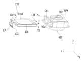
도 12는 도 11에 도시된 홀더(430)와 액체 렌즈 모듈(130)을 설명하기 위한 도면이다. 즉, 도 12는 홀더(430) 및 액체 렌즈부(130)의 분해 사시도를 나타낸다. 도 12에 도시된 홀더(430)는 제1 및 제2 홀(HO1, HO2)과 제1 내지 제4 측벽을 포함할 수 있다.FIG. 12 is a diagram for explaining the
제1 및 제2 홀(HO1, HO2)은 홀더(430)의 상부와 하부에 각각 형성되어, 홀더(430)의 상부와 하부를 각각 개방시킬 수 있다. 여기서, 제1 홀(HO1) 및 제2 홀(HO2)은 관통 홀일 수 있다. 제1 렌즈부(420)는 홀더(430)의 내부에 형성된 제1 홀(HO1)에 수용, 장착, 안착, 접촉, 고정, 가고정, 지지, 결합, 또는 배치될 수 있고, 제2 렌즈부(440)는 홀더(430)의 내부에 형성된 제2 홀(HO2)에 수용, 장착, 안착, 접촉, 고정, 가고정, 지지, 결합, 또는 배치될 수 있다.The first and second holes HO1 and HO2 are formed at the top and bottom of the
또한, 홀더(430)의 제1 및 제2 측벽은 광축(LX) 방향과 수직하는 방향(예를 들어, x축 방향)으로 서로 대면하여 배치되고, 제3 및 제4 측벽은 x축 방향 및 광축(LX) 방향 각각과 수직하는 방향(예를 들어, y축 방향)으로 서로 대면하여 배치될 수 있다. 또한, 도 12에 예시된 바와 같이 홀더(430)에서 제1 측벽은 제3 개구(OP3)를 포함하고, 제2 측벽은 제3 개구(OP3)와 같은 또는 유사한 형상의 제4 개구(OP4)를 포함할 수 있다. 따라서, 제1 측벽에 배치된 제3 개구(OP3)와 제2 측벽에 배치된 제4 개구(OP4)는 광축(LX) 방향과 수직인 방향(예를 들어, x축 방향)으로 서로 대면하여 배치될 수 있다.In addition, the first and second side walls of the
제3 및 제4 개구(OP3, OP4)에 의해 액체 렌즈 모듈(130)이 배치될 홀더(430)의 내부 공간이 개방될 수 있다. 이때, 액체 렌즈 모듈(130)은 제3 또는 제4 개구(OP3, OP4)를 통해 삽입되어 홀더(430)의 내부 공간에 장착, 안착, 접촉, 고정, 가고정, 지지, 결합, 또는 배치될 수 있다. 예를 들어, 액체 렌즈 모듈(130)은 제3 개구(OP3)를 통해 홀더(430)의 내부 공간에 삽입될 수 있다.The internal space of the
이와 같이, 액체 렌즈 모듈(130)이 제3 또는 제4 개구(OP3, OP4)를 통해 홀더(430) 내부 공간으로 삽입될 수 있도록, 광축(LX) 방향을 기준으로 홀더(430)의 제3 또는 제4 개구(OP3, OP4) 각각의 크기는 액체 렌즈 모듈(130)의 y축과 z축 방향으로의 단면적보다 클 수 있다. 예를 들어, 광축(LX) 방향으로 제3 및 제4 개구(OP3, OP4) 각각의 크기에 해당하는 높이(H)는 액체 렌즈 모듈(130)의 두께(TO)보다 클 수 있다.In this way, the
제2 렌즈부(440)는 홀더(430) 내부에서 액체 렌즈 모듈(130)의 아래에 배치될 수 있다. 제2 렌즈부(440)는 제1 렌즈부(420)와 광축 방향(예를 들어, z축 방향)으로 이격되어 배치될 수 있다.The second lens unit 440 may be disposed below the
카메라 모듈(1000A)의 외부로부터 제1 렌즈부(420)로 입사된 광은 액체 렌즈 모듈(130)을 통과하여 제2 렌즈부(440)로 입사될 수 있다. 제2 렌즈부(440)는 하나의 렌즈로 구현될 수도 있고, 중심축을 기준으로 정렬되어 광학계를 형성하는 2개 이상의 복수의 렌즈로 구현될 수도 있다.Light incident on the first lens unit 420 from the outside of the camera module 1000A may pass through the
액체 렌즈 모듈(130)과 달리, 제1 렌즈부(420) 및 제2 렌즈부(440) 각각은 고체 렌즈로서, 유리 또는 플라스틱으로 구현될 수 있으나, 실시 예는 제1 렌즈부(420) 및 제2 렌즈부(440) 각각의 특정한 재질에 국한되지 않는다.Unlike the
다시 도 11을 참조하면, 제1 커버(410)는 홀더(430), 액체 렌즈 모듈(130) 및 미들 베이스(450)를 둘러싸도록 배치되어, 이들(430, 130, 450)을 외부의 충격으로부터 보호할 수 있다. 특히, 제1 커버(410)가 배치됨으로써, 광학계를 형성하는 복수의 렌즈들을 외부 충격으로부터 보호할 수 있다.Referring again to FIG. 11, the first cover 410 is arranged to surround the
또한, 홀더(430)에 배치되는 제1 렌즈부(420)가 외부광에 노출될 수 있도록, 제1 커버(410)는 그(410)의 상부면에 형성된 상측 개구(410H)를 포함할 수 있다.Additionally, the first cover 410 may include an upper opening 410H formed on the upper surface of the
또한, 제1 커버(410)는 홀더(430)의 상면과 제1 내지 제4 측벽을 덮도록 배치될 수 있다.Additionally, the first cover 410 may be arranged to cover the top surface and first to fourth side walls of the
또한, 미들 베이스(450)는 홀더(430)의 제2 홀(HO2)을 둘러싸면서 배치될 수 있다. 이를 위해, 미들 베이스(450)는 제2 홀(HO2)을 수용하기 위한 수용홀(450H)을 포함할 수 있다.Additionally, the middle base 450 may be disposed surrounding the second hole HO2 of the
제1 커버(410)의 상측 개구(410H)와 마찬가지로 수용홀(450H)은 미들 베이스(450)의 중앙 부근에서, 카메라 모듈(1000A)에 배치된 이미지 센서(300)의 위치에 대응되는 위치에 형성될 수 있다.Like the upper opening 410H of the first cover 410, the receiving hole 450H is located near the center of the middle base 450, at a position corresponding to the position of the
미들 베이스(450)는 메인 기판(480) 상에서 회로 소자(481)와 이격되어 메인 기판(480)에 장착될 수 있다. 즉, 홀더(430)는 회로 소자(481)와 이격되어 메인 기판(480) 상에 배치될 수 있다.The middle base 450 may be mounted on the main board 480 while being spaced apart from the circuit element 481 on the main board 480 . That is, the
메인 기판(480)은 미들 베이스(450)의 하부에 배치되고, 이미지 센서(300)가 장착, 안착, 접촉, 고정, 가고정, 지지, 결합, 또는 수용될 수 있는 홈, 회로 소자(481), 연결부(또는, FPCB)(482) 및 커넥터(483)를 포함할 수 있다.The main board 480 is disposed at the lower part of the middle base 450, and has a groove and a circuit element 481 in which the
메인 기판(480)의 회로 소자(481)는 액체 렌즈 모듈(130) 및 이미지 센서(300)를 제어하는 제어 모듈을 구성할 수 있다. 회로 소자(481)는 수동 소자 및 능동 소자 중 적어도 하나를 포함할 수 있으며, 다양한 넓이 및 높이를 가질 수 있다. 회로 소자(481)는 복수 개일 수 있으며, 메인 기판(480)의 높이보다 높은 높이를 가지면서 외부로 돌출될 수 있다. 복수의 회로 소자(481)는 홀더(430)와 광축(LX)에 평행한 방향상에서 오버랩 되지 않도록 배치될 수 있다. 예를 들어, 복수의 회로 소자(481)는 파워 인덕터(power inductor) 및 자이로 센서 등을 포함할 수 있으나, 실시 예는 회로 소자(481)의 특정한 종류에 국한되지 않는다.The circuit element 481 of the main board 480 may form a control module that controls the
또한, 회로 소자(481)는 도 1에 도시된 출력단자 OUT를 통해 출력되는 전압값(VS1, VS2)을 이용하여 온도 검출 소자(120)의 온도를 산정할 수도 있고, 커넥터(483)를 통해 외부로 전송할 수도 있다. 또한, 회로 소자(481)는 도 8에 도시된 제1 내지 제6 스위치(S1 내지 S6)를 포함할 수도 있으며, 이들(S1 내지 S6)의 턴 온 또는 턴 오프를 제어하는 스위치 제어 신호를 생성할 수도 있다.In addition, the circuit element 481 may calculate the temperature of the
메인 기판(480)은 홀더(430)가 배치되는 홀더 영역과 복수의 회로소자(481)가 배치되는 소자 영역을 포함할 수 있다.The main board 480 may include a holder area where the
메인 기판(480)은 FPCB(482)를 포함하는 RFPCB(Rigid Flexible Printed Circuit Board)로 구현될 수 있다. FPCB(482)는 카메라 모듈(1000A)이 장착되는 공간이 요구하는 바에 따라 벤딩될 수 있다.The main board 480 may be implemented as a Rigid Flexible Printed Circuit Board (RFPCB) including the FPCB 482. The FPCB (482) can be bent as required by the space where the camera module (1000A) is mounted.
한편, 커넥터(483)는 메인 기판(480)을 카메라 모듈(1000A) 외부의 전원 또는 기타 다른 장치(예를 들어, application processor)와 전기적으로 연결할 수 있다.Meanwhile, the connector 483 may electrically connect the main board 480 to a power source external to the camera module 1000A or another device (eg, an application processor).
한편, 도 11에 도시된 복수의 회로 소자(481) 중 일부는 전자 방해(EMI: electromagnetic interference)나 노이즈를 야기할 수 있다. 특히, 복수의 회로 소자(481) 중 파워 인덕터(481-1)는 다른 소자보다 더 많은 EMI를 야기할 수 있다. 이와 같이, EMI나 노이즈를 차단하기 위해, 회로 커버(472)는 메인 기판(480)의 소자 영역에 배치된 회로 소자(481)를 덮도록 배치될 수 있다.Meanwhile, some of the plurality of circuit elements 481 shown in FIG. 11 may cause electromagnetic interference (EMI) or noise. In particular, among the plurality of circuit elements 481, the power inductor 481-1 may cause more EMI than other elements. In this way, in order to block EMI or noise, the circuit cover 472 may be arranged to cover the circuit element 481 disposed in the element area of the main board 480.
또한, 회로 커버(472)가 회로 소자(481)를 덮도록 배치될 경우, 메인 기판(480)의 상부에 배치된 회로 소자(481)가 외부 충격으로부터 보호될 수 있다. 이를 위해 회로 커버(472)는 메인 기판(480)에 배치된 회로 소자(481)의 형상 및 위치를 고려하여 회로 소자(481)를 수용하여 덮기 위한 수용 공간을 포함할 수 있다.Additionally, when the circuit cover 472 is arranged to cover the circuit element 481, the circuit element 481 disposed on the main board 480 can be protected from external shock. To this end, the circuit cover 472 may include an accommodating space for accommodating and covering the circuit element 481 in consideration of the shape and position of the circuit element 481 disposed on the main board 480.
한편, 필터(470)는 제1 렌즈부(420), 액체 렌즈 모듈(130) 및 제2 렌즈부(440)를 통과한 광에 대해 특정 파장 범위에 해당하는 광을 필터링할 수 있다. 필터(470)는 적외선(IR) 차단 필터 또는 자외선(UV) 차단 필터일 수 있으나, 실시 예는 이에 한정되지 않는다. 필터(470)는 이미지 센서(300) 위에 배치될 수 있다. 필터(470)는 센서 베이스(460)의 내부에 배치될 수 있다.Meanwhile, the filter 470 may filter light corresponding to a specific wavelength range for light that has passed through the first lens unit 420, the
센서 베이스(460)는 미들 베이스(450)의 하부에 배치되고 메인 기판(480)에 부착될 수 있다. 센서 베이스(460)는 이미지 센서(300)를 둘러싸고 이미지 센서(300)를 외부의 이물질 또는 충격으로부터 보호할 수 있다.The sensor base 460 may be placed below the middle base 450 and attached to the main board 480. The sensor base 460 may surround the
메인 기판(480)은 센서 베이스(460)의 아래에 배치되고, 메인 기판(480) 상에 회로 소자(481)와 이격되어 센서 베이스(460)가 장착되며, 센서 베이스(460)의 위로 미들 베이스(450), 제2 렌즈부(440), 액체 렌즈 모듈(130) 및 제1 렌즈부(420)가 배치된 홀더(430)가 배치될 수 있다.The main board 480 is disposed below the sensor base 460, the sensor base 460 is mounted on the main board 480 and spaced apart from the circuit element 481, and the middle base is above the sensor base 460. 450 , a
이하, 비교 례 및 실시 예에 의한 카메라 모듈을 다음과 같이 비교하여 설명한다. 여기서, 언급되는 비교 례는 실시 예에 의한 카메라 모듈이 갖는 효과의 이해를 돕기 위해 도시한 것에 불과하다.Hereinafter, camera modules according to comparative examples and examples will be compared and described as follows. Here, the comparative examples mentioned are merely shown to help understand the effects of the camera module according to the embodiment.
도 13은 비교 례에 의한 카메라 모듈의 국부적인 평면도를 나타낸다.Figure 13 shows a local plan view of the camera module according to a comparative example.
도 13에 도시된 비교 례에 의한 카메라 모듈은 액체 렌즈(10) 및 서미스터(20)로 구성된다.The camera module according to the comparative example shown in FIG. 13 consists of a
액체 렌즈(10)는 공통 전극(CO) 및 절연층(IS)을 포함할 수 있다. 여기서, 공통 전극(CO) 및 절연층(IS)은 전술한 실시 예에 의한 제2 전극(E2) 및 절연층(IS1, IS2)에 각각 해당한다. 절연층(IS)은 생략될 수 있다. 서미스터(20)는 전술한 실시 예에 의한 온도 검출 소자(120)와 같이 액체 렌즈(10)의 온도를 감지하기 위해 이용되는 동일한 역할을 수행한다.The
평면상에서 도 13에 도시된 비교 례에 의한 서미스터(20)는 액체 렌즈(10)의 일측에 치우쳐서 배치된다. 이로 인해, 서미스터(20)의 패턴의 라인(20L)의 길이가 길어지고, 라인(20L) 간 거리가 좁아지기 때문에, 열에 의해 라인(20L)이 변형될 수도 있고, 구조적 설계가 복잡하고 및 제조 공정이 어려울 수 있다. 반면에, 실시 예에 의한 카메라 모듈(1000, 1000A)의 경우, 제1 온도 검출 소자(122A, 122B)와 제2 온도 검출 소자(124A, 124B)를 액체 렌즈(110A)의 제1 면(SF1)의 양측에 배치하므로, 온도 검출 소자(120A, 120B)의 라인간 길이를 길게 구현할 필요도 없고, 라인 간 간격(예를 들어, 도 6에 도시된 ‘d’)이 도 13에 도시된 비교 례보다 넓을 수 있다. 따라서, 비교 례와 비교할 때, 실시 예에 의한 온도 검출 소자(120A, 120B)는 열에 의해 그(120A, 120B)의 라인이 변형될 염려가 적고, 구조적 설계가 단순화되고, 제조 공정이 용이해질 수 있다.The
또한, 도 3을 참조하면, 개별 전극인 제1 전극(E1)이 배치되는 제1 플레이트(P1)의 제1 면(SF1)에서 제1 개구(O1)의 면적은 공통 전극인 제2 전극(E2)이 배치되는 제1 플레이트(P1)의 제2 면(SF2)에서 제2 개구(O2)의 면적보다 작다. 이를 고려할 때, 온도 검출 소자(120A, 120B)를 배치할 수 있는 면적이 제1 플레이트(P1)의 제2 면(SF2)보다 제1 면(SF1)이 더 크다. 도 13에 도시된 비교 례의 경우 공통 전극(CO)이 배치되는 제2 면(SF2) 상에 서미스터(20)가 배치된다. 이 경우, 서미스터(20)와 공통 전극(CO)을 충분히 이격시키지 않으면, 공통 전극(CO)에 연결된 제1 액체(LQ1)와 서미스터(20)가 서로 단락될 수도 있다. 이를 방지하기 위해, 서미스터(20)와 공통 전극(CO)을 충분히 이격시키기 위해, 액체 렌즈(10)의 면적을 크게 제조할 수 밖에 없다. 반면에, 실시 예에 의하면, 제2 면(SF2)보다 더 넓은 제1 면(SF1) 위에 온도 검출 소자(120A, 120B)를 배치하기 때문에, 비교 례와 비교할 때 액체 렌즈(110A)의 면적을 키울 필요도 없고 온도 검출 소자(120A, 120B)와 공통 전극(CO)인 제2 전극(E2)이 단락될 염려도 없다. 이와 같이, 실시 예는 비교 례보다 우수한 전기적 특성을 가질 수 있다.In addition, referring to FIG. 3, the area of the
게다가, 비교 례의 경우 서미스터(20)가 한 개이므로 서미스터(20)의 동작에 필요한 저항값 및 변화량을 조정함에 있어서 제한을 받는다. 반면에, 실시 례에 의한 카메라 모듈의 경우 온도 검출 소자(120A, 120B)가 복수 개이므로 온도 검출 소자(120A, 120B)의 동작에 필요한 저항값 및 변화량을 조정함에 있어서 비교 례보다 제한을 덜 받을 수 있다.In addition, in the case of the comparative example, there is only one
실시 예와 관련하여 전술한 바와 같이 몇 가지만을 기술하였지만, 이외에도 다양한 형태의 실시가 가능하다. 앞서 설명한 실시 예들의 기술적 내용들은 서로 양립할 수 없는 기술이 아닌 이상은 다양한 형태로 조합될 수 있으며, 이를 통해 새로운 실시형태로 구현될 수도 있다.Although only a few examples have been described as described above, various other forms of implementation are possible. The technical contents of the above-described embodiments can be combined in various forms unless they are incompatible technologies, and through this, can be implemented as a new embodiment.
한편, 전술한 실시 예에 의한 액체 렌즈를 포함하는 카메라 모듈(1000, 1000A)을 이용하여 광학 기기를 구현할 수 있다. 여기서, 광학 기기는 광 신호를 가공하거나 분석할 수 있는 장치를 포함할 수 있다. 광학 기기의 예로는 카메라/비디오 장치, 망원경 장치, 현미경 장치, 간섭계 장치, 광도계 장치, 편광계 장치, 분광계 장치, 반사계 장치, 오토콜리메이터 장치, 렌즈미터 장치 등이 있을 수 있으며, 렌즈 어셈블리를 포함할 수 있는 광학 기기에 본 실시 예를 적용할 수 있다.Meanwhile, an optical device can be implemented using the
또한, 광학 기기는 스마트폰, 노트북 컴퓨터, 태블릿 컴퓨터 등의 휴대용 장치로 구현될 수 있다. 이러한 광학 기기는 카메라 모듈(1000, 1000A), 영상을 출력하는 디스플레이부(미도시), 카메라 모듈(1000, 1000A)에 전원을 공급하는 배터리(미도시), 카메라 모듈(1000, 1000A)과 디스플레이부와 배터리를 실장하는 본체 하우징을 포함할 수 있다. 광학 기기는 타 기기와 통신할 수 있는 통신모듈과, 데이터를 저장할 수 있는 메모리부를 더 포함할 수 있다. 통신 모듈과 메모리부 역시 본체 하우징에 실장될 수 있다.Additionally, the optical device may be implemented as a portable device such as a smartphone, laptop computer, or tablet computer. These optical devices include a camera module (1000, 1000A), a display unit (not shown) that outputs images, a battery (not shown) that supplies power to the camera module (1000, 1000A), a camera module (1000, 1000A), and a display. It may include a main housing in which the unit and battery are mounted. The optical device may further include a communication module capable of communicating with other devices and a memory unit capable of storing data. The communication module and memory unit may also be mounted in the main housing.
본 발명은 본 발명의 정신 및 필수적 특징을 벗어나지 않는 범위에서 다른 특정한 형태로 구체화될 수 있음은 당업자에게 자명하다. 따라서, 상기의 상세한 설명은 모든 면에서 제한적으로 해석되어서는 아니되고 예시적인 것으로 고려되어야 한다. 본 발명의 범위는 첨부된 청구항의 합리적 해석에 의해 결정되어야 하고, 본 발명의 등가적 범위 내에서의 모든 변경은 본 발명의 범위에 포함된다.It is obvious to those skilled in the art that the present invention can be embodied in other specific forms without departing from the spirit and essential features of the present invention. Accordingly, the above detailed description should not be construed as restrictive in all respects and should be considered illustrative. The scope of the present invention should be determined by reasonable interpretation of the appended claims, and all changes within the equivalent scope of the present invention are included in the scope of the present invention.
1000, 1000A: 카메라 모듈100: 렌즈 어셈블리
110, 110A: 액체 렌즈120, 120A, 120B: 온도 검출 소자
200: 제어 회로300: 이미지 센서1000, 1000A: Camera module 100: Lens assembly
110, 110A:
200: control circuit 300: image sensor
Claims (7)
Translated fromKorean상기 제1 플레이트의 상기 제1 면 상에서 상기 개별 전극과 이격되어 배치되는 복수의 온도검출소자; 및
상기 복수의 온도검출소자와 연결되어 상기 액체 렌즈의 온도를 감지하는 온도 감지부를 포함하고,
상기 복수의 온도검출소자는 서로 이격되어 배치되는 제1 및 제2 온도검출소자를 포함하고,
상기 온도 감지부는 상기 제1 온도검출소자의 일단과 연결되고, 상기 제1 온도검출소자의 타단은 상기 제2 온도검출소자의 일단과 연결되고, 상기 제2 온도검출소자의 타단은 기준 전위와 연결되어, 상기 온도 감지부는 상기 제1 및 제2 온도 검출 소자의 온도 정보를 감지하는 카메라 모듈.first plate; and a liquid lens including individual electrodes disposed on a first side of the first plate;
a plurality of temperature detection elements disposed on the first surface of the first plate and spaced apart from the individual electrodes; and
A temperature detection unit connected to the plurality of temperature detection elements to detect the temperature of the liquid lens,
The plurality of temperature detection elements include first and second temperature detection elements arranged to be spaced apart from each other,
The temperature detection unit is connected to one end of the first temperature detection element, the other end of the first temperature detection element is connected to one end of the second temperature detection element, and the other end of the second temperature detection element is connected to a reference potential. A camera module in which the temperature detection unit detects temperature information of the first and second temperature detection elements.
상기 개별전극과 연결된 연결 기판;
이미지 센서; 및
상기 이미지 센서가 실장된 메인 기판을 포함하고,
상기 온도 감지부는 상기 메인 기판에 배치되는 카메라 모듈.According to claim 1,
a connection board connected to the individual electrodes;
image sensor; and
It includes a main board on which the image sensor is mounted,
The temperature sensing unit is a camera module disposed on the main board.
상기 제1 온도검출소자의 상기 일단과 상기 타단은 상기 액체 렌즈의 제1 에지영역에 배치되고,
상기 제2 온도검출소자의 상기 일단과 상기 타단은 상기 액체 렌즈의 상기 제1 에지영역의 반대측 제2 에지영역에 배치되는 카메라 모듈.According to claim 1,
The one end and the other end of the first temperature detection element are disposed in a first edge area of the liquid lens,
The camera module wherein the one end and the other end of the second temperature detection element are disposed in a second edge area of the liquid lens opposite to the first edge area.
상기 제1 온도검출소자의 상기 일단에 구동 신호를 공급하는 감지 구동부; 및
상기 제1 온도검출소자의 상기 일단에 연결되어 상기 복수의 온도검출소자의 상기 온도 정보를 측정하는 온도 정보 측정부를 포함하는 카메라 모듈.The method of claim 1, wherein the temperature sensing unit
a sensing driver that supplies a driving signal to the one end of the first temperature sensing element; and
A camera module comprising a temperature information measurement unit connected to the one end of the first temperature detection element and measuring the temperature information of the plurality of temperature detection elements.
Priority Applications (4)
| Application Number | Priority Date | Filing Date | Title |
|---|---|---|---|
| KR1020180164475AKR102645839B1 (en) | 2018-12-18 | 2018-12-18 | Camera module including liquid lens |
| CN201980092473.XACN113454976B (en) | 2018-12-18 | 2019-12-13 | Camera module including liquid lens |
| PCT/KR2019/017682WO2020130503A1 (en) | 2018-12-18 | 2019-12-13 | Camera module including liquid lens |
| US17/415,935US12298586B2 (en) | 2018-12-18 | 2019-12-13 | Camera module including liquid lens |
Applications Claiming Priority (1)
| Application Number | Priority Date | Filing Date | Title |
|---|---|---|---|
| KR1020180164475AKR102645839B1 (en) | 2018-12-18 | 2018-12-18 | Camera module including liquid lens |
Publications (2)
| Publication Number | Publication Date |
|---|---|
| KR20200075611A KR20200075611A (en) | 2020-06-26 |
| KR102645839B1true KR102645839B1 (en) | 2024-03-08 |
Family
ID=71102265
Family Applications (1)
| Application Number | Title | Priority Date | Filing Date |
|---|---|---|---|
| KR1020180164475AActiveKR102645839B1 (en) | 2018-12-18 | 2018-12-18 | Camera module including liquid lens |
Country Status (4)
| Country | Link |
|---|---|
| US (1) | US12298586B2 (en) |
| KR (1) | KR102645839B1 (en) |
| CN (1) | CN113454976B (en) |
| WO (1) | WO2020130503A1 (en) |
Families Citing this family (1)
| Publication number | Priority date | Publication date | Assignee | Title |
|---|---|---|---|---|
| DE102023100922A1 (en)* | 2023-01-16 | 2024-07-18 | Optotune Switzerland Ag | OIS system and method for controlling the OIS system |
Family Cites Families (18)
| Publication number | Priority date | Publication date | Assignee | Title |
|---|---|---|---|---|
| DE602004030365D1 (en)* | 2003-10-22 | 2011-01-13 | Nippon Kogaku Kk | EXPOSURE DEVICE, EXPOSURE METHOD AND METHOD FOR MANUFACTURING COMPONENTS |
| JP4760426B2 (en)* | 2006-02-13 | 2011-08-31 | ソニー株式会社 | Optical element and lens array |
| JP2008158195A (en) | 2006-12-22 | 2008-07-10 | Nikon Corp | Camera and optical device |
| JP2009025523A (en)* | 2007-07-19 | 2009-02-05 | Nikon Corp | Optical element, optical system and optical apparatus, and imaging method |
| WO2010073127A2 (en) | 2008-12-23 | 2010-07-01 | Varioptic S.A. | Optical electrowetting device |
| JP2010286740A (en)* | 2009-06-12 | 2010-12-24 | Optoelectronics Co Ltd | Optical information reader |
| US10712529B2 (en)* | 2013-03-13 | 2020-07-14 | Cognex Corporation | Lens assembly with integrated feedback loop for focus adjustment |
| US9575221B2 (en)* | 2013-12-31 | 2017-02-21 | Cognex Corporation | Systems and methods reduce temperature induced drift effects on a liquid lens |
| KR102634910B1 (en)* | 2016-09-05 | 2024-02-07 | 엘지이노텍 주식회사 | Liquid lens, lens module, camera module, optical apparatus and manufacturing method of lens module |
| KR20180087082A (en)* | 2017-01-24 | 2018-08-01 | 엘지이노텍 주식회사 | Liquid lens, camera module and optical device/instrument including the same |
| CN110463181B (en)* | 2017-01-24 | 2021-07-23 | Lg伊诺特有限公司 | Camera module including liquid lens module and method of controlling camera module |
| KR102319454B1 (en) | 2017-03-20 | 2021-10-28 | 엘지이노텍 주식회사 | Liquid lens |
| WO2018187578A2 (en)* | 2017-04-05 | 2018-10-11 | Corning Incorporated | Liquid lens feedback and control |
| KR101821189B1 (en)* | 2017-04-11 | 2018-01-23 | 엘지이노텍 주식회사 | Control circuit of liquid lens, camera module and controlling method for liquid lens |
| EP3611562B1 (en) | 2017-04-11 | 2021-12-08 | LG Innotek Co., Ltd. | Liquid lens control circuit, camera module and liquid lens control method |
| KR102310998B1 (en) | 2017-04-11 | 2021-10-12 | 엘지이노텍 주식회사 | Camera module and method for controlling liquid lens |
| TW201939070A (en)* | 2018-03-09 | 2019-10-01 | 美商康寧公司 | Camera modules comprising liquid lenses and heating devices |
| KR102500653B1 (en)* | 2018-05-04 | 2023-02-16 | 엘지이노텍 주식회사 | Control circuit of liquid lens, camera module and controlling method for liquid lens |
- 2018
- 2018-12-18KRKR1020180164475Apatent/KR102645839B1/enactiveActive
- 2019
- 2019-12-13USUS17/415,935patent/US12298586B2/enactiveActive
- 2019-12-13WOPCT/KR2019/017682patent/WO2020130503A1/ennot_activeCeased
- 2019-12-13CNCN201980092473.XApatent/CN113454976B/enactiveActive
Also Published As
| Publication number | Publication date |
|---|---|
| US12298586B2 (en) | 2025-05-13 |
| KR20200075611A (en) | 2020-06-26 |
| CN113454976A (en) | 2021-09-28 |
| WO2020130503A1 (en) | 2020-06-25 |
| US20220066122A1 (en) | 2022-03-03 |
| CN113454976B (en) | 2023-08-04 |
Similar Documents
| Publication | Publication Date | Title |
|---|---|---|
| KR102645131B1 (en) | Camera module including liquid lens, and method for controlling the module | |
| US11372140B2 (en) | Liquid lens, camera module, and optical device including the same | |
| JP7287984B2 (en) | LIQUID LENS, CAMERA MODULE INCLUDING SUCH LENS, AND METHOD OF CONTROLLING LIQUID LENS | |
| KR102645839B1 (en) | Camera module including liquid lens | |
| KR102714150B1 (en) | Camera module | |
| KR102761690B1 (en) | Liquid lens, camera module including the same and method for controlling the module | |
| KR102531130B1 (en) | Dual camera module including liquid lens | |
| US12392984B2 (en) | Camera module including liquid lens, and control method thereof | |
| KR102820991B1 (en) | Optical device | |
| US11740390B2 (en) | Liquid lens and lens assembly including same | |
| KR102607336B1 (en) | Liquid lens module | |
| KR102708150B1 (en) | Lens assembly and camera module including the lens assembly | |
| KR20190127430A (en) | Lens assembly and camera module including the lens assembly | |
| KR20190133429A (en) | Lens assembly and camera module including the lens assembly | |
| KR102781351B1 (en) | Camera module | |
| KR20200092645A (en) | Liquid lens |
Legal Events
| Date | Code | Title | Description |
|---|---|---|---|
| PA0109 | Patent application | Patent event code:PA01091R01D Comment text:Patent Application Patent event date:20181218 | |
| PG1501 | Laying open of application | ||
| PA0201 | Request for examination | Patent event code:PA02012R01D Patent event date:20211129 Comment text:Request for Examination of Application Patent event code:PA02011R01I Patent event date:20181218 Comment text:Patent Application | |
| E902 | Notification of reason for refusal | ||
| PE0902 | Notice of grounds for rejection | Comment text:Notification of reason for refusal Patent event date:20230621 Patent event code:PE09021S01D | |
| E701 | Decision to grant or registration of patent right | ||
| PE0701 | Decision of registration | Patent event code:PE07011S01D Comment text:Decision to Grant Registration Patent event date:20231206 | |
| GRNT | Written decision to grant | ||
| PR0701 | Registration of establishment | Comment text:Registration of Establishment Patent event date:20240305 Patent event code:PR07011E01D | |
| PR1002 | Payment of registration fee | Payment date:20240306 End annual number:3 Start annual number:1 | |
| PG1601 | Publication of registration |