KR102640517B1 - Bottle cap contained functional food - Google Patents
Bottle cap contained functional foodDownload PDFInfo
- Publication number
- KR102640517B1 KR102640517B1KR1020210147653AKR20210147653AKR102640517B1KR 102640517 B1KR102640517 B1KR 102640517B1KR 1020210147653 AKR1020210147653 AKR 1020210147653AKR 20210147653 AKR20210147653 AKR 20210147653AKR 102640517 B1KR102640517 B1KR 102640517B1
- Authority
- KR
- South Korea
- Prior art keywords
- container
- main body
- functional food
- filling container
- sealing member
- Prior art date
- Legal status (The legal status is an assumption and is not a legal conclusion. Google has not performed a legal analysis and makes no representation as to the accuracy of the status listed.)
- Active
Links
- 235000013376functional foodNutrition0.000titleclaimsabstractdescription61
- 238000007789sealingMethods0.000claimsabstractdescription58
- 238000005520cutting processMethods0.000claimsabstractdescription40
- 230000008878couplingEffects0.000claimsdescription14
- 238000010168coupling processMethods0.000claimsdescription14
- 238000005859coupling reactionMethods0.000claimsdescription14
- 235000013361beverageNutrition0.000description11
- 239000000463materialSubstances0.000description8
- 238000002347injectionMethods0.000description6
- 239000007924injectionSubstances0.000description6
- 239000007788liquidSubstances0.000description5
- 239000000126substanceSubstances0.000description4
- BQCADISMDOOEFD-UHFFFAOYSA-NSilverChemical compound[Ag]BQCADISMDOOEFD-UHFFFAOYSA-N0.000description3
- 239000000428dustSubstances0.000description3
- 230000004927fusionEffects0.000description3
- 230000036541healthEffects0.000description3
- 239000000203mixtureSubstances0.000description3
- 239000000843powderSubstances0.000description3
- 229920003002synthetic resinPolymers0.000description3
- 239000000057synthetic resinSubstances0.000description3
- 241000196324EmbryophytaSpecies0.000description2
- 230000008901benefitEffects0.000description2
- 230000006866deteriorationEffects0.000description2
- 238000010586diagramMethods0.000description2
- 235000020510functional beverageNutrition0.000description2
- 238000012986modificationMethods0.000description2
- 230000004048modificationEffects0.000description2
- 230000000149penetrating effectEffects0.000description2
- 238000003825pressingMethods0.000description2
- 102000008186CollagenHuman genes0.000description1
- 108010035532CollagenProteins0.000description1
- 235000002789Panax ginsengNutrition0.000description1
- 230000004308accommodationEffects0.000description1
- 235000007215black sesameNutrition0.000description1
- 239000002775capsuleSubstances0.000description1
- 229920001436collagenPolymers0.000description1
- 238000004891communicationMethods0.000description1
- 238000009826distributionMethods0.000description1
- 230000035622drinkingEffects0.000description1
- 230000000694effectsEffects0.000description1
- 239000008187granular materialSubstances0.000description1
- 235000013402health foodNutrition0.000description1
- 235000001497healthy foodNutrition0.000description1
- 241000411851herbal medicineSpecies0.000description1
- 230000036571hydrationEffects0.000description1
- 238000006703hydration reactionMethods0.000description1
- 238000004519manufacturing processMethods0.000description1
- 230000004044responseEffects0.000description1
- 229940088594vitaminDrugs0.000description1
- 229930003231vitaminNatural products0.000description1
- 235000013343vitaminNutrition0.000description1
- 239000011782vitaminSubstances0.000description1
- 150000003722vitamin derivativesChemical class0.000description1
- XLYOFNOQVPJJNP-UHFFFAOYSA-NwaterSubstancesOXLYOFNOQVPJJNP-UHFFFAOYSA-N0.000description1
Images


Classifications
- B—PERFORMING OPERATIONS; TRANSPORTING
- B65—CONVEYING; PACKING; STORING; HANDLING THIN OR FILAMENTARY MATERIAL
- B65D—CONTAINERS FOR STORAGE OR TRANSPORT OF ARTICLES OR MATERIALS, e.g. BAGS, BARRELS, BOTTLES, BOXES, CANS, CARTONS, CRATES, DRUMS, JARS, TANKS, HOPPERS, FORWARDING CONTAINERS; ACCESSORIES, CLOSURES, OR FITTINGS THEREFOR; PACKAGING ELEMENTS; PACKAGES
- B65D51/00—Closures not otherwise provided for
- B65D51/24—Closures not otherwise provided for combined or co-operating with auxiliary devices for non-closing purposes
- B65D51/28—Closures not otherwise provided for combined or co-operating with auxiliary devices for non-closing purposes with auxiliary containers for additional articles or materials
- B65D51/2807—Closures not otherwise provided for combined or co-operating with auxiliary devices for non-closing purposes with auxiliary containers for additional articles or materials the closure presenting means for placing the additional articles or materials in contact with the main contents by acting on a part of the closure without removing the closure, e.g. by pushing down, pulling up, rotating or turning a part of the closure, or upon initial opening of the container
- B65D51/2814—Closures not otherwise provided for combined or co-operating with auxiliary devices for non-closing purposes with auxiliary containers for additional articles or materials the closure presenting means for placing the additional articles or materials in contact with the main contents by acting on a part of the closure without removing the closure, e.g. by pushing down, pulling up, rotating or turning a part of the closure, or upon initial opening of the container the additional article or materials being released by piercing, cutting or tearing an element enclosing it
- B65D51/2828—Closures not otherwise provided for combined or co-operating with auxiliary devices for non-closing purposes with auxiliary containers for additional articles or materials the closure presenting means for placing the additional articles or materials in contact with the main contents by acting on a part of the closure without removing the closure, e.g. by pushing down, pulling up, rotating or turning a part of the closure, or upon initial opening of the container the additional article or materials being released by piercing, cutting or tearing an element enclosing it said element being a film or a foil
- B65D51/2835—Closures not otherwise provided for combined or co-operating with auxiliary devices for non-closing purposes with auxiliary containers for additional articles or materials the closure presenting means for placing the additional articles or materials in contact with the main contents by acting on a part of the closure without removing the closure, e.g. by pushing down, pulling up, rotating or turning a part of the closure, or upon initial opening of the container the additional article or materials being released by piercing, cutting or tearing an element enclosing it said element being a film or a foil ruptured by a sharp element, e.g. a cutter or a piercer
- B—PERFORMING OPERATIONS; TRANSPORTING
- B65—CONVEYING; PACKING; STORING; HANDLING THIN OR FILAMENTARY MATERIAL
- B65D—CONTAINERS FOR STORAGE OR TRANSPORT OF ARTICLES OR MATERIALS, e.g. BAGS, BARRELS, BOTTLES, BOXES, CANS, CARTONS, CRATES, DRUMS, JARS, TANKS, HOPPERS, FORWARDING CONTAINERS; ACCESSORIES, CLOSURES, OR FITTINGS THEREFOR; PACKAGING ELEMENTS; PACKAGES
- B65D81/00—Containers, packaging elements, or packages, for contents presenting particular transport or storage problems, or adapted to be used for non-packaging purposes after removal of contents
- B65D81/32—Containers, packaging elements, or packages, for contents presenting particular transport or storage problems, or adapted to be used for non-packaging purposes after removal of contents for packaging two or more different materials which must be maintained separate prior to use in admixture
- B65D81/3216—Rigid containers disposed one within the other
- B65D81/3222—Rigid containers disposed one within the other with additional means facilitating admixture
Landscapes
- Engineering & Computer Science (AREA)
- Mechanical Engineering (AREA)
- Closures For Containers (AREA)
Abstract
Translated fromKoreanDescription
Translated fromKorean본 발명은 기능성식품이 충진된 용기의 뚜껑에 관한 것이다.The present invention relates to a lid of a container filled with functional food.
최근에 건강에 대한 관심이 증대됨에 따라 건강식품을 찾는 사람이 많아지고 있다. 건강에 대한 관심이 증대됨에 따라 사람들은 마시는 음료를 단순히 수분 또는 미각을 충족시키기 위한 것 뿐만 아니라 건강까지 고려되어야 하는 것으로 인식하게 되었다. 이러한 요구에 맞춰 비타민 캡슐 및 분말, 콜라겐, 과립, 홍삼, 검은깨, 한약 등과 같은 액상 또는 분말의 기능성식품을 함유한 혼합음료의 수요가 늘어나고 있다.Recently, as interest in health has increased, more and more people are looking for healthy foods. As interest in health has increased, people have come to recognize that drinking beverages is not just for hydration or to satisfy taste, but also as something that should take health into consideration. In response to these demands, the demand for mixed drinks containing liquid or powdered functional foods such as vitamin capsules and powders, collagen, granules, red ginseng, black sesame seeds, and herbal medicine is increasing.
그러나 혼합음료는 제조과정에서 혼합되어야 하는 문제점과 유통기한에 따른 혼합음료의 변질우려 등 많은 제약이 따르는 문제점이 있다. 따라서, 많은 사람들이 직간접적으로 기능성식품을 분말 또는 액상 형태로 물이나 음료 등에 혼합하여 마시는 것이 일상적이다.However, mixed drinks have many limitations, such as having to be mixed during the manufacturing process and concerns about deterioration of mixed drinks depending on their expiration date. Therefore, it is common for many people to directly or indirectly mix functional foods in powder or liquid form with water or drinks.
한편, 병 또는 용기에 가루형태의 기능성식품을 혼합하는 경우에 병 또는 용기의 외측으로 기능성식물을 흘리는 경우가 빈번하게 발생되고, 액상 형태의 기능성식품을 혼합하는 경우에도 적량을 혼합하기 어려워 복용 효과가 미미할 수 있다.On the other hand, when mixing functional food in powder form in a bottle or container, functional plants often spill out of the bottle or container, and even when mixing functional food in liquid form, it is difficult to mix the right amount to reduce the effect of taking it. may be insignificant.
따라서, 병 또는 용기에 기능성식품을 정량 및 용이하게 혼합할 수 있는 연구가 필요하다.Therefore, research is needed to measure and easily mix functional foods in bottles or containers.
따라서 본 발명이 해결하고자 하는 기술적 과제는 휴대가 용이하며 필요에 따라 적량의 기능성식품과 음료를 용이하게 혼합하여 마실수 있는 기능성식품이 충진된 용기의 뚜껑을 제공하는 것이다.Therefore, the technical problem to be solved by the present invention is to provide a lid for a container filled with functional food that is easy to carry and can be easily mixed with an appropriate amount of functional food and beverage as needed.
본 발명의 일 측면에 따르면, 중공형상을 가지되, 하단부에 마련되어 용기의 주입구에 나사결합되는 나사산과, 상단부에 마련된 수용공간을 구비한 본체; 상기 본체의 개방된 하단부에 결합되어 상기 본체의 하단부를 밀봉하는 제1 밀봉부재; 상기 본체의 개방된 상단부에 삽입되어 상기 수용공간에 배치되되, 하단부에 일체로 또는 결합되어 하단부를 밀봉하는 제2 밀봉부재를 구비하며 내부에 기능성식품이 충진된 충진용기; 하부가 상기 충진용기의 상단부에 결합되어 상기 충진용기의 개방된 상단부를 밀폐하고, 측부가 상기 본체의 상단부에 결합되어 상기 본체의 개방된 상단부를 밀폐하는 캡부재; 및 상기 수용공간에 마련되고 상기 충진용기의 하부에 배치되며 상기 본체가 상기 용기의 주입구에 나사결합되는 경우에 상방으로 상대 이동되고 상기 제2 밀봉부재를 절개하여 상기 충진용기에 충진된 기능성식품을 상기 용기에 공급하는 절개부재를 포함하는 기능성식품이 충진된 용기의 뚜껑.이 제공될 수 있다.According to one aspect of the present invention, a main body having a hollow shape, a screw thread provided at the lower end and screwed to the inlet of the container, and a receiving space provided at the upper end; a first sealing member coupled to the open lower end of the main body to seal the lower end of the main body; a filling container inserted into the open upper part of the main body and placed in the receiving space, the filling container having a second sealing member integrally or combined with the lower part to seal the lower part, and the functional food being filled therein; a cap member whose lower part is coupled to the upper end of the filling container to seal the open upper part of the filling container, and whose side part is coupled to the upper end of the main body to seal the open upper end of the main body; And it is provided in the receiving space and disposed at the lower part of the filling container, and when the main body is screwed to the inlet of the container, it is relatively moved upward and cuts the second sealing member to release the functional food filled in the filling container. A lid of a container filled with functional food including a cutting member supplied to the container may be provided.
상기 본체는 내면에서 수평방향으로 연장되게 형성되어 상기 절개부재가 안착되며, 중심부에 기능성식품이 관통하는 제1 관통홀이 형성된 수평확장부; 및 상기 수평확장부의 하면에서 하방으로 연장되게 형성되며 상기 용기의 주입구에 대향되는 일면에 상기 나사산이 형성된 수직확장부를 더 포함하며, 상기 절개부재는 상기 제1 관통홀과 연통되게 형성된 복수의 제2 관통홀을 포함할 수 있다.The main body is formed to extend in a horizontal direction from the inner surface, on which the cutting member is seated, and has a horizontal expansion portion formed at the center with a first through hole through which the functional food penetrates; and a vertical expansion portion formed to extend downward from the lower surface of the horizontal expansion portion and having the screw thread formed on one surface opposite to the inlet of the container, wherein the cutting member is formed to be in communication with the first through hole. It may include a through hole.
상기 수평확장부는 원주방향을 따라 상호 이격되게 형성된 복수의 결합홀을 더 포함하며, 상기 절개부재는 하면에 돌출 형성되어 상기 결합홀에 관통 삽입되고, 끝단이 상기 용기의 주입구의 상단부에 밀착되는 복수의 결합돌기를 더 포함할 수 있다.The horizontal extension further includes a plurality of coupling holes formed to be spaced apart from each other along the circumferential direction, and the cutting member is formed to protrude from the lower surface and is inserted through the coupling hole, and a plurality of plurality of cutting members whose ends are in close contact with the upper end of the inlet of the container. It may further include coupling protrusions.
상기 절개부재는 중심부에서 하방으로 절곡되게 형성되어 상기 본체가 상기 용기의 주입구에 나사결합되어 상방으로 상대 이동되는 경우에 상기 충진용기의 하단부가 삽입되며, 상기 제1 관통홀과 연통되는 상기 복수의 제2 관통홀이 형성된 제1 오목부; 상기 제1 오목부의 바닥면에서 상방으로 돌출되게 형성되되, 중심부에 상기 제1 관통홀과 연통되는 제3 관통홀이 형성된 기둥체; 및The cutting member is formed to be bent downward from the center so that when the main body is screwed to the inlet of the container and relatively moved upward, the lower end of the filling container is inserted, and the plurality of the plurality of cells communicating with the first through hole are inserted. a first concave portion in which a second through hole is formed; a pillar formed to protrude upward from the bottom surface of the first concave portion and having a third through hole in the center communicating with the first through hole; and
상기 기둥체의 상단부에 원주방향을 따라 상호 이격되게 형성된 복수의 절개날을 더 포함하며, 상기 수평확장부는 중심부에서 하방으로 절곡되게 형성되어 상기 제1 오목부가 삽입되는 제2 오목부를 더 포함할 수 있다.It may further include a plurality of cutting blades spaced apart from each other along the circumferential direction at the upper end of the column body, and the horizontal extension may be formed to be bent downward from the center and further include a second concave portion into which the first concave portion is inserted. there is.
상기 제2 밀봉부재는 원주방향을 따라 형성된 반칼라인을 포함할 수 있다.The second sealing member may include a half-color line formed along the circumferential direction.
상기 캡부재와 상기 충진용기의 상단부 사이에 마련되어 상기 캡부재가 상기 충진용기의 상단부에 결합되는 경우에 상기 충진용기의 상단부를 밀봉하거나, 상기 충진용기의 상단부에 결합되어 상기 충진용기의 상단부를 밀봉하는 제3 밀봉부재를 더 포함할 수 있다.It is provided between the cap member and the upper end of the filling container to seal the upper end of the filling container when the cap member is coupled to the upper end of the filling container, or is coupled to the upper end of the filling container to seal the upper end of the filling container. It may further include a third sealing member.
상기 캡부재의 측부는 상기 본체의 상단부 내면에 걸림결합될 수 있다.The side portion of the cap member may be engaged with the inner surface of the upper end of the main body.
본 발명의 실시예는 기능성식품이 충진된 용기의 뚜껑을 음료가 수용된 병 또는 용기에 결합하는 동작만으로 기능성식품과 음료를 용이하게 혼합할 수 있다.In an embodiment of the present invention, functional food and beverage can be easily mixed simply by coupling the lid of the container filled with functional food to the bottle or container containing the beverage.
또한 본 발명의 실시예는 기능성식품이 충진된 뚜껑만을 휴대하고, 필요한 경우에 음료를 구입한 후 병 또는 용기에 뚜껑을 결합하는 동작만으로 기능성식품과 혼합된 음료를 음용할 수 있으므로, 휴대가 용이하고 사용상의 편의성을 향상시킬 수 있다.In addition, the embodiment of the present invention is easy to carry because it is possible to carry only the lid filled with the functional food and, if necessary, drink the beverage mixed with the functional food by simply attaching the lid to the bottle or container after purchasing the beverage. and can improve convenience of use.
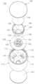
도 1은 본 발명에 따른 기능성식품이 충진된 용기의 뚜껑을 나타내는 사시도이다.
도 2 내지 도 4는 본 발명에 따른 기능성식품이 충진된 용기의 뚜껑을 나타내는 분해도이다.
도 5는 본 발명에 따른 기능성식품이 충진된 용기의 뚜껑을 나타내는 단면도이다.
도 6 내지 도 8은 본 발명에 따른 기능성식품이 충진된 용기의 뚜껑의 사용상태도이다.Figure 1 is a perspective view showing the lid of a container filled with functional food according to the present invention.
Figures 2 to 4 are exploded views showing the lid of a container filled with functional food according to the present invention.
Figure 5 is a cross-sectional view showing the lid of a container filled with functional food according to the present invention.
Figures 6 to 8 are diagrams showing the use of the lid of a container filled with functional food according to the present invention.
본 발명과 본 발명의 동작상의 이점 및 본 발명의 실시에 의하여 달성되는 목적을 충분히 이해하기 위해서는 본 발명의 바람직한 실시 예를 예시하는 첨부 도면 및 첨부 도면에 기재된 내용을 참조하여야만 한다.In order to fully understand the present invention, its operational advantages, and the objectives achieved by practicing the present invention, reference should be made to the accompanying drawings illustrating preferred embodiments of the present invention and the contents described in the accompanying drawings.
이하, 첨부된 도면을 참조하여 본 발명의 바람직한 실시 예를 설명함으로써, 본 발명을 상세히 설명한다. 각 도면에 제시된 동일한 참조부호는 동일한 부재를 나타낸다.Hereinafter, the present invention will be described in detail by explaining preferred embodiments of the present invention with reference to the attached drawings. The same reference numerals in each drawing indicate the same member.
도 1은 본 발명에 따른 기능성식품이 충진된 용기의 뚜껑을 나타내는 사시도이고, 도 2 내지 도 4는 본 발명에 따른 기능성식품이 충진된 용기의 뚜껑을 나타내는 분해도이고, 도 5는 본 발명에 따른 기능성식품이 충진된 용기의 뚜껑을 나타내는 단면도이다.Figure 1 is a perspective view showing the lid of a container filled with functional food according to the present invention, Figures 2 to 4 are exploded views showing the lid of the container filled with functional food according to the present invention, and Figure 5 is an exploded view showing the lid of the container filled with functional food according to the present invention. This is a cross-sectional view showing the lid of a container filled with functional food.
도 1 내지 도 5를 참조하면, 본 발명에 따른 기능성식품이 충진된 용기의 뚜껑(100)은 용기(200)의 주입구(210)에 결합되는 본체(110)와, 본체(110)의 하단부를 밀봉하는 제1 밀봉부재(120)와, 본체(110)의 내부에 수용되며 기능성식품(D)이 충진된 충진용기(160)와, 본체(110)의 상단부를 밀폐하는 캡부재(140)와, 본체(110)의 내부에 마련되고 충진용기(160)의 하부에 배치되며 본체(110)가 용기(200)의 주입구(210)에 나사결합되는 경우에 상방으로 상대 이동되어 충진용기(160)의 하단부를 절개하는 절개부재(150)를 포함한다.Referring to Figures 1 to 5, the
본 발명에 따른 기능성식품(D)이 충진된 용기의 뚜껑(100)은 그 자체를 용기(200)의 주입구(210)에 결합하는 동작만으로 기능성식품(D)을 용기에 공급하고 음료에 혼합할 수 있다.The
또한 본 발명에 따른 기능성식품(D)이 충진된 용기의 뚜껑(100)은 휴대가 용이하며 용기(200)의 주입구(210)에 결합하는 동작만으로 기능성식품(D)과 혼합된 음료를 음용할 수 있으므로 사용상의 편의성을 향상시킬 수 있다.In addition, the
또한 본 발명에 따른 기능성식품(D)이 충진된 용기의 뚜껑(100)을 사용하는 경우에, 기능성식품(D)과 음료를 미리 혼합하지 않아도 되므로 유통기간 중 변질될 수 있는 염려없이, 건강식품 또는 음료를 쉽게 마실 수 있는 이점이 있다.In addition, when using the
본 실시예에 따른 본체(110)는 용기(200)의 주입구(210)에 결합되어 용기(200)를 밀봉하는 역할을 한다.The
본체(110)는 상단부와 하단부가 관통된 중공형상으로 형성된다.The
그리고 본체(110)는 하단부에 마련되어 용기(200)의 주입구(210)에 나사결합되는 제1 나사산(111)과, 상단부의 내부에 마련된 수용공간(112)과, 내면에서 수평방향으로 연장되게 형성된 수평확장부(113)와, 수평확장부(113)의 하면에서 하방으로 연장되게 형성된 수직확장부(117)를 포함한다.And the
수평확장부(113)는 본체(110)의 내부를 구획하며, 수평확장부(113)의 하부는 용기(200)의 주입구(210)에 결합되고 수평확장부(113)의 상부는 후술할 충진용기(160) 및 절개부재(150)가 수용되는 수용공간(112)을 형성한다.The
수직확장부(117)는 수평확장부(113)의 하면에서 하방으로 연장되게 형성되며 용기(200)의 주입구(210)의 외측에서 이격되게 배치된다. 그리고 본체(110)가 용기(200)의 주입구(210)에 나사결합될 수 있도록 수직확장부(117)의 용기(200)의 주입구(210)에 대향되는 일면에 제1 나사산(111)이 형성된다.The
그리고 이물질이 본체(110)의 개방된 하단부를 통해 내부로 유입되는 것을 방지하도록 본체(110)의 개방된 하단부에는 제1 밀봉부재(120)가 결합된다(도 1 및 도 5 참조).And a
제1 밀봉부재(120)는 수분, 먼지 등의 이물질이 통과할 수 없는 불투과성이고, 본체(110)를 용기(200)의 주입구(210)에 결합하고자 하는 경우에 본체(110)의 하단부에서 용이하게 박리될 수 있는 재질로 제조된다. 예를들어 제1 밀봉부재(120)는 얇은 은박지, 합성수지 필름 등으로 제조될 수 있으나, 이에 한정되지 않고 다양한 재질로 제조될 수 있다. 또한 제1 밀봉부재(120)는 본체(110)의 하단부에 고주파 실링, 열융착 등 다양한 방식으로 결합될 수 있다.The
본 실시예에 따른 충진용기(160)는 내부에 기능성식물을 충진하는 역할을 한다.The
충진용기(160)는 본체(110)의 개방된 상단부에 삽입되어 수용공간(112)에 배치된다. 그리고 충진용기(160)의 하단부에는 제2 밀봉부재(161)가 마련되어 충진용기(160)의 하단부를 밀봉한다.The
제2 밀봉부재(161)는 충진용기(160)의 하단부에 일체로 형성되거나 충진용기(160)의 하단부에 결합되어 충진용기(160)의 하단부를 밀봉한다.The
제2 밀봉부재(161)는 후술할 절개부재(150)에 의해 용이하게 절개될 수 있도록 원주방향을 따라 형성된 반칼라인(162)을 포함한다(도 5 참조). 반칼라인(162)은 제2 밀봉부재(161)에 원주방향을 따라 연속되게 또는 상호 이격되게 형성될 수 있다.The
본체(110)가 용기(200)의 주입구(210)에 나사결합되어 하강하는 경우에 절개부재(150)에 의해 제2 밀봉부재(161)가 가압되면 제2 밀봉부재(161)는 반칼라인(162)을 따라 용이하게 절개되며, 충진용기(160)의 내부에 충진된 기능성식품(D)은 하방으로 낙하되어 용기(200)로 공급된다.When the
또한 제2 밀봉부재(161)는 수분, 먼지 등의 이물질이 통과할 수 없는 불투과성 재질로 제조된다. 그리고 제2 밀봉부재(161)가 충진용기(160)의 하단부에 일체로 형성되는 경우에 충진용기(160)와 동일한 재질로 제조된다. 또한 제2 밀봉부재(161)가 충진용기(160)의 하단부에 결합되는 경우에 절개부재(150)에 의해 용이하게 절개될 수 있는 재질로 제조된다. 예를들어 제2 밀봉부재(161)는 얇은 은박지, 합성수지 필름 등으로 제조될 수 있으나, 이에 한정되지 않고 다양한 재질로 제조될 수 있다. 또한 제2 밀봉부재(161)는 충진용기(160)의 하단부에 고주파 실링, 열융착 등 다양한 방식으로 결합될 수 있다.Additionally, the
본 실시예에 따른 캡부재(140)는 충진용기(160)의 개방된 상단부 및 본체(110)의 개방된 상단부에 결합되어 충진용기(160)의 상단부 및 본체(110)의 상단부를 밀폐하는 역할을 한다.The
캡부재(140)의 하부에는 제2 나사산(141)이 형성되어, 충진용기(160)의 상단부에 형성된 제3 나사산(163)과 나사결합된다. 캡부재(140)와 충진용기(160)가 상호 나사결합됨에 따라 충진용기(160)의 상단부가 밀폐된다.A
한편, 본 실시예에서는 충진용기(160)의 개방된 상단부를 밀봉하도록 제3 밀봉부재(130)가 마련될 수 있다. 특히 충진용기(160)의 내부에 액상의 기능성식품(D)이 충진되는 경우에 액상의 기능성식품(D)이 충진용기(160)의 외부로 누설되는 것을 방지하기 위해 추가적으로 제3 밀봉부재(130)를 마련할 수 있다.Meanwhile, in this embodiment, a
제3 밀봉부재(130)는 캡부재(140)와 충진용기(160)의 상단부 사이에 마련되어 캡부재(140)가 충진용기(160)의 상단부에 나사결합되는 경우에 충진용기(160)의 상단부에 압착되어 충진용기(160)의 상단부를 밀봉할 수 있다.The
또한 제3 밀봉부재(130)는 충진용기(160)의 상단부에 결합되어 충진용기(160)의 상단부를 밀봉할 수 있다.Additionally, the
제3 밀봉부재(130)는 수분, 먼지 등의 이물질이 통과할 수 없는 불투과성의 재질로 제조된다. 예를들어 제3 밀봉부재(130)는 얇은 은박지, 합성수지 필름 등으로 제조될 수 있으나, 이에 한정되지 않고 다양한 재질로 제조될 수 있다. 또한 제3 밀봉부재(130)는 충진용기(160)의 상단부에 고주파 실링, 열융착 등 다양한 방식으로 결합될 수 있다.The
그리고 캡부재(140)와 충진용기(160)를 상호 나사결합한 후, 충진용기(160)를 본체(110)의 개방된 상단부에 삽입하고 캡부재(140)의 측부와 본체(110)의 상단부를 상호 결합하여 본체(110)의 개방된 상단부를 밀폐한다. 이때 캡부재(140)의 측부는 본체(110)의 상단부 내면에 걸림결합될 수 있다. 즉, 도시되지는 않았으나 캡부재(140)를 가압하는 경우에 캡부재(140)의 측부에 마련된 걸림돌기(미도시)가 본체(110)의 상단부 내면에 형성된 걸림홈(미도시)에 삽입되어 걸림결합될 수 있다.After screwing the
본 실시예에 따른 절개부재(150)는 충진용기(160)의 하단부에 마련된 제2 밀봉부재(161)를 절개하여 충진용기(160)의 내부에 충진된 기능성식품(D)을 용기(200)에 공급하는 역할을 한다.The cutting
절개부재(150)는 본체(110)의 수용공간(112)에 마련되고 충진용기(160)의 하부에 배치된다. 즉 본 실시예에서 따른 절개부재(150)는 수평확장부(113)의 상면에 안착되고 충진용기(160)의 하부에 배치되며, 수평확장부(113)에 결합되어 측방향 이동이 제한된다.The cutting
이를 위해, 도 2에서 도시한 바와 같이, 수평확장부(113)는 원주방향을 따라 상호 이격되게 형성된 복수의 결합홀(115)을 포함한다. 복수의 결합홀(115)은 용기(200)의 주입구(210) 상단부 테두리 위치에 대응되는 위치에 상호 이격되게 배치된다.To this end, as shown in FIG. 2, the
그리고 도 3에서 도시한 바와 같이, 절개부재(150)는 하면에 돌출되게 형성되어 복수의 결합홀(115)에 관통 삽입되는 복수의 결합돌기(152)를 포함한다.And as shown in FIG. 3, the cutting
본체(110)가 용기(200)의 주입구(210)에 결합되는 경우에 복수의 결합돌기(152)의 끝단은 용기(200)의 주입구(210)의 상단부에 밀착된다.When the
결합돌기(152)들의 끝단이 용기(200)의 주입구(210)의 상단부에 밀착되므로 본체(110)가 용기(200)의 주입구(210)에 나사결합되어 하방으로 이동되는 경우에 용기(200)의 주입구(210)에 의해 결합돌기(152)가 상대적으로 상방으로 이동되고 이에 따라 절개부재(150) 자체가 상방으로 상대 이동되어 충진용기(160)의 하단부에 결합된 제2 밀봉부재(161)를 절개한다.Since the ends of the engaging
제2 밀봉부재(161)가 절개되는 경우에 기능성식품(D)은 충진용기(160)에서 순차로 절개부재(150)와 수평확장부(113)를 통과한 후 용기(200)의 주입구(210)에 공급된다.When the
한편, 제2 밀봉부재(161)를 절개하기 위해, 절개부재(150)는 중심부에 형성된 제1 오목부(153)와, 제1 오목부(153)에 상방으로 돌출되게 형성된 기둥체(154)와, 기둥체(154)의 상단부에 형성된 복수의 절개날(156)을 포함한다.Meanwhile, in order to cut the
제1 오목부(153)는 중심부에서 하방으로 절곡된 형상으로 형성된다. 제1 오목부(153)에는 수평확장부(113)의 중심부에 형성된 제1 관통홀(114)과 연통되는 복수의 제2 관통홀(151)이 형성된다.The first
본체(110)가 용기(200)의 주입구(210)에 나사결합되어 하방으로 이동되고 이에 따라 절개부재(150)가 상방으로 상대 이동되는 경우에 충진용기(160)의 하단부는 제1 오목부(153)에 삽입된다.When the
기둥체(154)는 제1 오목부(153)의 바닥면에서 상방으로 돌출되게 형성된다. 그리고 기둥체(154)는 상단부와 하단부가 관통된 중공형상으로 형성된다. 즉 기둥체(154)의 중심부에 제1 관통홀(114)과 연통되는 제3 관통홀(155)이 형성된다. 한편 기둥체(154)가 제1 오목부(153)의 바닥면에서 상방으로 돌출되게 형성되므로, 복수의 제2 관통홀(151)은 기둥체(154)의 외측 둘레를 따라 배치될 수 있다.The
복수의 절개날(156)은 기둥체(154)의 상단부에 원주방향을 따라 상호 이격되게 형성되고, 제2 밀봉부재(161)에 대향되게 배치된다. 절개부재(150)가 상방으로 상대 이동되는 경우에 복수의 절개날(156)이 제2 밀봉부재(161)를 가압하고 절개한다. 전술한 바와 같이, 제2 밀봉부재(161)에는 원주방향을 따라 반칼라인(162)이 형성되므로 제2 밀봉부재(161)를 용이하게 절개할 수 있다.A plurality of cutting
한편, 절개부재(150)가 수평확장부(113)에 안착되고 중심부에 하방으로 절곡되게 형성된 제1 오목부(153)를 구비하므로, 이에 대응하여 수평확장부(113)는 중심부에서 하방으로 절곡되게 형성되어 제1 오목부(153)가 삽입되는 제2 오목부(116)를 더 포함한다. 그리고 본체(110)가 용기(200)의 주입구(210)에 나사결합되는 경우에 제2 오목부(116)는 용기(200)의 주입구(210) 내부로 삽입된다.Meanwhile, since the
전술한 바와 같이 복수의 제2 관통홀(151)과 제3 관통홀(155)이 제1 오목부(153)에 형성되므로, 제2 오목부(116)에 제1 관통홀(114)을 형성하여 기능성식품(D)이 용기(200)의 주입구(210)로 용이하게 공급되게 한다.As described above, since a plurality of second through
상기와 같이 구성되는 본 발명에 따른 기능성식품(D)이 충진된 용기의 뚜껑(100)의 사용상태를 설명하면 다음과 같다.The use state of the
도 6 내지 도 8은 본 발명에 따른 기능성식품이 충진된 용기의 뚜껑의 사용상태도이다.Figures 6 to 8 are diagrams showing the use of the lid of a container filled with functional food according to the present invention.
용기(200) 내의 음료에 기능성식품(D)을 혼합하고자 하는 경우에 먼저 기존의 용기(200)의 주입구(210)에 결합된 뚜껑을 제거한다. 그리고 도 6에서 도시한 바와 같이, 본체(110)의 하단부에 결합된 제1 밀봉부재(120)를 박리한다.When attempting to mix the functional food (D) with the beverage in the
그리고 도 7에서 도시한 바와 같이, 본체(110)의 제2 오목부(116)를 용기(200)의 주입구(210)에 삽입하고, 본체(110)를 회전시켜 용기(200)의 주입구(210)에 뚜껑(100)을 결합한다.As shown in FIG. 7, the second
도 7은 본체(110)가 용기(200)의 주입구(210)에 나사결합된 경우에도 절개날(156)이 제2 밀봉부재(161)를 가압 및 절개하기 전 상태이므로, 기능성식품(D)은 충진용기(160) 내에 그대로 잔존한다.Figure 7 shows that even when the
그리고, 도 8에서 도시한 바와 같이, 용기(200) 내의 음료와 기능성식품(D)을 혼합하고자 하는 경우에 충진용기(160)의 하단부에 결합된 제2 밀봉부재(161)를 가압 및 절개하여야 한다.And, as shown in FIG. 8, when attempting to mix the beverage and functional food (D) in the
이를 위해, 본체(110)를 시계방향으로 더욱 회전시켜 본체(110)를 하방으로 이동시키면, 본체(110)가 하방으로 이동됨에 따라 용기(200)의 주입구(210)에 밀착된 결합돌기(152)가 상방으로 상대 이동되고 이와 함께 절개부재(150)의 기둥체(154) 및 절개날(156)이 상방으로 상대 이동된다.To this end, when the
본체(110)의 하방 이동이 증가될수록 상대적으로 절개부재(150)의 상방이동이 증가되므로, 절개날(156)이 제2 밀봉부재(161)를 가압하는 가압력이 증가되고 이에 따라 제2 밀봉부재(161)는 반칼라인(162)을 따라 절개된다.As the downward movement of the
제2 밀봉부재(161)가 절개되는 경우에 충진용기(160) 내의 기능성식품(D)이 하방으로 낙하되고 제2 관통홀(151) 및 제3 관통홀(155)과 제1 관통홀(114)을 통과하여 용기(200)의 주입구(210)에 공급된다.When the
그리고 소비자는 기능성식품(D)이 용기(200)로 공급된 후 용기(200)를 흔들어 기능성식품(D)과 음료를 혼합하여 음용할 수 있다.And after the functional food (D) is supplied to the
이와 같이 본 발명은 기재된 실시 예에 한정되는 것이 아니고, 본 발명의 사상 및 범위를 벗어나지 않고 다양하게 수정 및 변형할 수 있음은 이 기술의 분야에서 통상의 지식을 가진 자에게 자명하다. 따라서 그러한 수정 예 또는 변형 예들은 본 발명의 특허청구범위에 속한다 하여야 할 것이다.As such, the present invention is not limited to the described embodiments, and it is obvious to those skilled in the art that various modifications and changes can be made without departing from the spirit and scope of the present invention. Accordingly, such modifications or variations should be considered to fall within the scope of the claims of the present invention.
100: 기능성식품이 충진된 용기의 뚜껑 110: 본체
111: 제1 나사산 112: 수용공간
113: 수평확장부 114: 제1 관통홀
115: 결합홀 116: 제2 오목부
117: 수직확장부 120: 제1 밀봉부재
130: 제3 밀봉부재 140: 캡부재
141: 제2 나사산 150: 절개부재
151: 제2 관통홀 152: 결합돌기
153: 제1 오목부 154: 기둥체
155: 제3 관통홀 156: 절개날,
160: 충진용기 161: 제2 밀봉부재
162: 반칼라인 163: 제3 나사산
200: 용기 210: 주입구100: Lid of container filled with functional food 110: Body
111: first thread 112: accommodation space
113: horizontal expansion part 114: first through hole
115: coupling hole 116: second concave portion
117: vertical expansion part 120: first sealing member
130: third sealing member 140: cap member
141: second thread 150: cutting member
151: second through hole 152: coupling protrusion
153: first concave portion 154: pillar body
155: third through hole 156: cutting blade,
160: Filling container 161: Second sealing member
162: Half collar 163: Third thread
200: Container 210: Inlet
Claims (7)
Translated fromKorean상기 본체의 개방된 하단부에 결합되어 상기 본체의 하단부를 밀봉하는 제1 밀봉부재;
상기 본체의 개방된 상단부에 삽입되어 상기 수용공간에 배치되되, 하단부에 일체로 또는 결합되어 하단부를 밀봉하는 제2 밀봉부재를 구비하며 내부에 기능성식품이 충진된 충진용기;
하부가 상기 충진용기의 상단부에 결합되어 상기 충진용기의 개방된 상단부를 밀폐하고, 측부가 상기 본체의 상단부에 결합되어 상기 본체의 개방된 상단부를 밀폐하는 캡부재; 및
상기 수용공간에 마련되고 상기 충진용기의 하부에 배치되며 상기 본체가 상기 용기의 주입구에 나사결합되는 경우에 상방으로 상대 이동되고 상기 제2 밀봉부재를 절개하여 상기 충진용기에 충진된 기능성식품을 상기 용기에 공급하는 절개부재를 포함하며,
상기 본체는,
내면에서 수평방향으로 연장되게 형성되어 상기 절개부재가 안착되며, 중심부에 기능성식품이 관통하는 제1 관통홀이 형성된 수평확장부; 및
상기 수평확장부의 하면에서 하방으로 연장되게 형성되며 상기 용기의 주입구에 대향되는 일면에 상기 나사산이 형성된 수직확장부를 더 포함하며,
상기 절개부재는 상기 제1 관통홀과 연통되게 형성된 복수의 제2 관통홀을 포함하는 기능성식품이 충진된 용기의 뚜껑.A main body having a hollow shape, a screw thread provided at the lower end and screwed to the inlet of the container, and a receiving space provided at the upper end;
a first sealing member coupled to the open lower end of the main body to seal the lower end of the main body;
a filling container inserted into the open upper part of the main body and placed in the receiving space, the filling container having a second sealing member integrally or combined with the lower part to seal the lower part, and the functional food being filled therein;
a cap member whose lower part is coupled to the upper end of the filling container to seal the open upper part of the filling container, and whose side part is coupled to the upper end of the main body to seal the open upper end of the main body; and
It is provided in the receiving space and disposed at the lower part of the filling container, and when the main body is screwed to the inlet of the container, it is relatively moved upward and the second sealing member is cut to store the functional food filled in the filling container. It includes a cutting member supplied to the container,
The main body is,
a horizontal expansion portion formed to extend horizontally from the inner surface, into which the cutting member is seated, and having a first through hole through which the functional food penetrates at the center; and
It is formed to extend downward from the lower surface of the horizontal expansion portion and further includes a vertical expansion portion having the screw thread formed on one side opposite to the inlet of the container,
The cutting member is a lid of a container filled with functional food including a plurality of second through holes formed to communicate with the first through hole.
상기 수평확장부는,
원주방향을 따라 상호 이격되게 형성된 복수의 결합홀을 더 포함하며,
상기 절개부재는,
하면에 돌출 형성되어 상기 결합홀에 관통 삽입되고, 끝단이 상기 용기의 주입구의 상단부에 밀착되는 복수의 결합돌기를 더 포함하는 기능성식품이 충진된 용기의 뚜껑.According to paragraph 1,
The horizontal expansion part,
It further includes a plurality of coupling holes formed to be spaced apart from each other along the circumferential direction,
The cutting member is,
A lid of a container filled with functional food, further comprising a plurality of engaging protrusions protruding from the lower surface and inserted into the engaging hole, the ends of which are in close contact with the upper end of the inlet of the container.
상기 절개부재는,
중심부에서 하방으로 절곡되게 형성되어 상기 본체가 상기 용기의 주입구에 나사결합되어 상방으로 상대 이동되는 경우에 상기 충진용기의 하단부가 삽입되며, 상기 제1 관통홀과 연통되는 상기 복수의 제2 관통홀이 형성된 제1 오목부;
상기 제1 오목부의 바닥면에서 상방으로 돌출되게 형성되되, 중심부에 상기 제1 관통홀과 연통되는 제3 관통홀이 형성된 기둥체; 및
상기 기둥체의 상단부에 원주방향을 따라 상호 이격되게 형성된 복수의 절개날을 더 포함하며,
상기 수평확장부는,
중심부에서 하방으로 절곡되게 형성되어 상기 제1 오목부가 삽입되는 제2 오목부를 더 포함하는 기능성식품이 충진된 용기의 뚜껑.According to paragraph 3,
The cutting member is,
It is formed to be bent downward from the center, so that the lower end of the filling container is inserted when the main body is screwed to the inlet of the container and relatively moved upward, and the plurality of second through holes communicate with the first through hole. This formed first concave portion;
a pillar formed to protrude upward from the bottom surface of the first concave portion and having a third through hole in the center communicating with the first through hole; and
It further includes a plurality of cutting blades spaced apart from each other along the circumferential direction at the upper end of the column body,
The horizontal expansion part,
A lid of a container filled with functional food, further comprising a second concave portion that is bent downward from the center and into which the first concave portion is inserted.
상기 제2 밀봉부재는,
원주방향을 따라 형성된 반칼라인을 포함하는 기능성식품이 충진된 용기의 뚜껑.According to paragraph 1,
The second sealing member,
A lid of a container filled with functional food containing a half-color line formed along the circumferential direction.
상기 캡부재와 상기 충진용기의 상단부 사이에 마련되어 상기 캡부재가 상기 충진용기의 상단부에 결합되는 경우에 상기 충진용기의 상단부를 밀봉하거나, 상기 충진용기의 상단부에 결합되어 상기 충진용기의 상단부를 밀봉하는 제3 밀봉부재를 더 포함하는 기능성식품이 충진된 용기의 뚜껑.According to paragraph 1,
It is provided between the cap member and the upper end of the filling container to seal the upper end of the filling container when the cap member is coupled to the upper end of the filling container, or is coupled to the upper end of the filling container to seal the upper end of the filling container. A lid of a container filled with functional food further comprising a third sealing member.
상기 캡부재의 측부는 상기 본체의 상단부 내면에 걸림결합되는 기능성식품이 충진된 용기의 뚜껑.According to paragraph 1,
A lid of a container filled with functional food, wherein the side portion of the cap member is engaged with the inner surface of the upper end of the main body.
Priority Applications (1)
| Application Number | Priority Date | Filing Date | Title |
|---|---|---|---|
| KR1020210147653AKR102640517B1 (en) | 2021-11-01 | 2021-11-01 | Bottle cap contained functional food |
Applications Claiming Priority (1)
| Application Number | Priority Date | Filing Date | Title |
|---|---|---|---|
| KR1020210147653AKR102640517B1 (en) | 2021-11-01 | 2021-11-01 | Bottle cap contained functional food |
Publications (2)
| Publication Number | Publication Date |
|---|---|
| KR20230062948A KR20230062948A (en) | 2023-05-09 |
| KR102640517B1true KR102640517B1 (en) | 2024-02-27 |
Family
ID=86409534
Family Applications (1)
| Application Number | Title | Priority Date | Filing Date |
|---|---|---|---|
| KR1020210147653AActiveKR102640517B1 (en) | 2021-11-01 | 2021-11-01 | Bottle cap contained functional food |
Country Status (1)
| Country | Link |
|---|---|
| KR (1) | KR102640517B1 (en) |
Families Citing this family (1)
| Publication number | Priority date | Publication date | Assignee | Title |
|---|---|---|---|---|
| KR20250050998A (en)* | 2023-10-06 | 2025-04-16 | 바디텍메드(주) | Dissimilar substance mixing kit |
Citations (1)
| Publication number | Priority date | Publication date | Assignee | Title |
|---|---|---|---|---|
| JP2002059933A (en) | 2000-08-01 | 2002-02-26 | Hsu Lily | Separating and storing container |
Family Cites Families (4)
| Publication number | Priority date | Publication date | Assignee | Title |
|---|---|---|---|---|
| DE502005002600D1 (en)* | 2004-10-01 | 2008-03-06 | Belcap Ag | CAPSULE CLOSING |
| KR20090041265A (en)* | 2007-10-23 | 2009-04-28 | 김홍열 | Container to separate solid and liquid materials |
| KR101554665B1 (en) | 2015-05-20 | 2015-10-06 | (주)엠앤디글로벌 | Bottle equipped with pocket for functional particles |
| KR20170141333A (en)* | 2016-06-15 | 2017-12-26 | 김경중 | Pouch airtight container for drinking |
- 2021
- 2021-11-01KRKR1020210147653Apatent/KR102640517B1/enactiveActive
Patent Citations (1)
| Publication number | Priority date | Publication date | Assignee | Title |
|---|---|---|---|---|
| JP2002059933A (en) | 2000-08-01 | 2002-02-26 | Hsu Lily | Separating and storing container |
Also Published As
| Publication number | Publication date |
|---|---|
| KR20230062948A (en) | 2023-05-09 |
Similar Documents
| Publication | Publication Date | Title |
|---|---|---|
| KR101153695B1 (en) | Cap structure for beverage container | |
| EP2212216B1 (en) | Safety sealed reservoir cap | |
| US7308915B2 (en) | Packaging system for storing and mixing separate ingredient components | |
| US6959841B2 (en) | Closure with selectively operable dispense feature | |
| CN101056802B (en) | Disposable capsule for drinks and its opening method | |
| US20090020495A1 (en) | Container cap with liquid-dissolvable additive | |
| US20070102394A1 (en) | Closure device for a bottle | |
| JP2008532873A (en) | Container closures for containers that contain so-called “push-pull” closures | |
| CN112261893A (en) | Beverage ingredient pod | |
| WO1999044901A1 (en) | A container | |
| KR20130003384U (en) | Mixing cap | |
| US20180208363A1 (en) | Closing assembly for a container, such as bottles and/or flasks, removable cartridges, closing device, and method | |
| KR102640517B1 (en) | Bottle cap contained functional food | |
| CN102803086A (en) | Dispensing closure for container | |
| CN116547213A (en) | Dispensing apparatus, system and method | |
| KR100794167B1 (en) | Bottle cap for dropping and mixing different materials | |
| KR20190114661A (en) | Container lid for mixed materials | |
| JP4485189B2 (en) | Beverage container cap structure | |
| CN201436243U (en) | Storage room cover with safe seal | |
| CN212314386U (en) | Multi-material-cavity instant-mixing type bottle cap and bottle adopting same | |
| KR20110137003A (en) | Container caps and containers with their associated | |
| KR20060073397A (en) | Lid Structure of Drinkware | |
| KR101740663B1 (en) | The cap of beverage container for a built-in pill | |
| KR20090041265A (en) | Container to separate solid and liquid materials | |
| WO2013012322A1 (en) | Device for closing beverage containers, in particular a bottle, and assembly |
Legal Events
| Date | Code | Title | Description |
|---|---|---|---|
| PA0109 | Patent application | Patent event code:PA01091R01D Comment text:Patent Application Patent event date:20211101 | |
| PA0201 | Request for examination | ||
| PG1501 | Laying open of application | ||
| E902 | Notification of reason for refusal | ||
| PE0902 | Notice of grounds for rejection | Comment text:Notification of reason for refusal Patent event date:20231124 Patent event code:PE09021S01D | |
| E701 | Decision to grant or registration of patent right | ||
| PE0701 | Decision of registration | Patent event code:PE07011S01D Comment text:Decision to Grant Registration Patent event date:20240105 | |
| GRNT | Written decision to grant | ||
| PR0701 | Registration of establishment | Comment text:Registration of Establishment Patent event date:20240221 Patent event code:PR07011E01D | |
| PR1002 | Payment of registration fee | Payment date:20240222 End annual number:3 Start annual number:1 | |
| PG1601 | Publication of registration |