KR102639940B1 - Milimeter Wave Array Antenna Characteristics Measuring System - Google Patents
Milimeter Wave Array Antenna Characteristics Measuring SystemDownload PDFInfo
- Publication number
- KR102639940B1 KR102639940B1KR1020210150221AKR20210150221AKR102639940B1KR 102639940 B1KR102639940 B1KR 102639940B1KR 1020210150221 AKR1020210150221 AKR 1020210150221AKR 20210150221 AKR20210150221 AKR 20210150221AKR 102639940 B1KR102639940 B1KR 102639940B1
- Authority
- KR
- South Korea
- Prior art keywords
- signal
- network analyzer
- vector network
- channel
- array antenna
- Prior art date
- Legal status (The legal status is an assumption and is not a legal conclusion. Google has not performed a legal analysis and makes no representation as to the accuracy of the status listed.)
- Active
Links
- 238000005259measurementMethods0.000claimsabstractdescription79
- 230000010355oscillationEffects0.000claimsabstractdescription72
- 238000012360testing methodMethods0.000claimsdescription56
- 230000005540biological transmissionEffects0.000claimsdescription43
- 238000004364calculation methodMethods0.000claimsdescription3
- 238000010586diagramMethods0.000description10
- 230000005855radiationEffects0.000description5
- 238000011156evaluationMethods0.000description4
- 238000004891communicationMethods0.000description2
- 230000033001locomotionEffects0.000description2
- 239000011159matrix materialSubstances0.000description2
- 238000003012network analysisMethods0.000description2
- 238000006243chemical reactionMethods0.000description1
- 238000013461designMethods0.000description1
- 238000011161developmentMethods0.000description1
- 230000002500effect on skinEffects0.000description1
- 230000000694effectsEffects0.000description1
- 238000000034methodMethods0.000description1
- 238000012545processingMethods0.000description1
Images


Classifications
- G—PHYSICS
- G01—MEASURING; TESTING
- G01R—MEASURING ELECTRIC VARIABLES; MEASURING MAGNETIC VARIABLES
- G01R29/00—Arrangements for measuring or indicating electric quantities not covered by groups G01R19/00 - G01R27/00
- G01R29/08—Measuring electromagnetic field characteristics
- G01R29/10—Radiation diagrams of antennas
- G—PHYSICS
- G01—MEASURING; TESTING
- G01R—MEASURING ELECTRIC VARIABLES; MEASURING MAGNETIC VARIABLES
- G01R29/00—Arrangements for measuring or indicating electric quantities not covered by groups G01R19/00 - G01R27/00
- G01R29/08—Measuring electromagnetic field characteristics
- G01R29/0864—Measuring electromagnetic field characteristics characterised by constructional or functional features
- G01R29/0871—Complete apparatus or systems; circuits, e.g. receivers or amplifiers
- G—PHYSICS
- G01—MEASURING; TESTING
- G01R—MEASURING ELECTRIC VARIABLES; MEASURING MAGNETIC VARIABLES
- G01R29/00—Arrangements for measuring or indicating electric quantities not covered by groups G01R19/00 - G01R27/00
- G01R29/08—Measuring electromagnetic field characteristics
- G01R29/0864—Measuring electromagnetic field characteristics characterised by constructional or functional features
- G01R29/0878—Sensors; antennas; probes; detectors
- G—PHYSICS
- G01—MEASURING; TESTING
- G01R—MEASURING ELECTRIC VARIABLES; MEASURING MAGNETIC VARIABLES
- G01R29/00—Arrangements for measuring or indicating electric quantities not covered by groups G01R19/00 - G01R27/00
- G01R29/08—Measuring electromagnetic field characteristics
- G01R29/0864—Measuring electromagnetic field characteristics characterised by constructional or functional features
- G01R29/0892—Details related to signal analysis or treatment; presenting results, e.g. displays; measuring specific signal features other than field strength, e.g. polarisation, field modes, phase, envelope, maximum value
Landscapes
- Physics & Mathematics (AREA)
- Electromagnetism (AREA)
- General Physics & Mathematics (AREA)
- Variable-Direction Aerials And Aerial Arrays (AREA)
Abstract
Translated fromKoreanDescription
Translated fromKorean본 발명은 밀리미터파 안테나 특성 측정 시스템에 관한 것으로, 더 구체적으로 로터리 조인트와 다수의 벡터네트워크분석기용 확장모듈(Vector Network Analyzer Extension Module: VNAX)을 이용하여 모노펄스 배열 안테나 안테나의 특성을 신속하게 측정할 수 있는 밀리미터파 안테나 특성측정 시스템에 관한 것이다.The present invention relates to a millimeter wave antenna characteristic measurement system, and more specifically, to quickly measure the characteristics of a monopulse array antenna using a rotary joint and a number of vector network analyzer extension modules (VNAX). It is about a millimeter wave antenna characteristic measurement system that can
상용, 위성용, 군용 무선통신 시스템들은 보다 우수한 특성을 확보하기 위해서 밀리미터파 대역 주파수를 활발히 이용하고 있다. 밀리미터파를 이용하는 시스템의 최말단에는 대부분 송수신용 안테나가 이용되고 있다. 밀리미터파로 주파수가 높아질수록 동일 이득을 가정하는 경우, 안테나의 크기가 상대적으로 소형화되므로, 전체 시스템의 성능을 더욱 향상시키기 위해서 배열 안테나가 활발히 이용된다. 이 배열 안테나의 특성이 전체 시스템의 성능에 지대한 영향을 끼치므로, 정밀한 특성측정 평가 시스템의 개발은 매우 중요하다.Commercial, satellite, and military wireless communication systems are actively using millimeter wave band frequencies to secure better characteristics. Most transmitting and receiving antennas are used at the extreme end of systems that use millimeter waves. Assuming the same gain as the millimeter wave frequency increases, the size of the antenna becomes relatively small, so array antennas are actively used to further improve the performance of the overall system. Because the characteristics of this array antenna have a significant impact on the performance of the entire system, the development of a precise characteristic measurement and evaluation system is very important.
특히, 위치 추적은 무선 통신 분야에서 중요한 주제이며, 방향탐지를 위해서는 모노펄스 배열 안테나가 주로 사용된다. 위치 추적 성능은 배열 안테나의 특성에 크게 의존한다. 배열 안테나의 주요 성능은 이득과 방사패턴이므로, 배열 안테나의 성능들을 신속하고 정밀하게 측정할 수 있는 안테나 특성 측정 시스템이 요구된다.In particular, location tracking is an important topic in the wireless communication field, and monopulse array antennas are mainly used for direction finding. Position tracking performance greatly depends on the characteristics of the array antenna. Since the main performance of an array antenna is gain and radiation pattern, an antenna characteristic measurement system that can quickly and precisely measure the performance of the array antenna is required.
본 발명의 일 실시예에 따른 안테나 측정 시스템의 해결고자 하는 과제는 다수의 포트(또는 채널)를 보유한 로터리 조인트와 다수의 벡터네트워크분석기용 확장모듈(VNAX)를 이용하여 다채널을 수신할 수 있는 모노펄스 배열 안테나 특성평가 시스템을 제공하는 것이다.The problem to be solved by the antenna measurement system according to an embodiment of the present invention is to receive multiple channels using a rotary joint with a plurality of ports (or channels) and a plurality of vector network analyzer expansion modules (VNAX). It provides a monopulse array antenna characteristic evaluation system.
또한 본 발명의 일 실시예에 따른 안테나 측정 시스템의 해결고자 하는 과제는 다채널 측정시스템의 경우 방위각에 따른 합/차 수신신호의 신속한 측정을 제공함으로써 주요 성능들을 정확히 평가하는 것이다.In addition, the problem to be solved by the antenna measurement system according to an embodiment of the present invention is to accurately evaluate key performances by providing rapid measurement of sum/difference received signals according to azimuth in the case of a multi-channel measurement system.
본 발명의 일 실시예에 따른 안테나 측정 시스템의 해결고자 하는 과제는 방위각에 따른 합/차 채널을 동시에 측정하여 시간에 따른 위상 편자(Phase drift) 영향을 제거함으로써 합/차 신호의 정확한 이득 및 상대위상 측정을 제공하는 것이다.The problem to be solved by the antenna measurement system according to an embodiment of the present invention is to simultaneously measure the sum/difference channel according to the azimuth angle and remove the effect of phase drift over time, thereby providing accurate gain and relative frequency of the sum/difference signal. It provides phase measurements.
본 발명의 일 실시예에 따른 배열 안테나 측정 시스템은, RF 신호(RF) 및 국부 발진 신호(LO)를 출력하는 벡터 회로망 분석기; 상기 벡터 회로망 분석기에서 상기 RF 신호를 제공받아 주파수 체배하여 주파수 체배 RF 신호(n x RF)를 송신 안테나에 전달하고, 상기 주파수 체배 RF 신호(n x RF)와 상기 국부 발진 신호(LO)를 사용하여 다운 컨버젼하여 기준 중간 주파수 신호(REF IF)를 생성하고, 상기 기준 중간 주파수 신호(REF IF)를 상기 벡터 회로망 분석기에 제공하는 송신 벡터 회로망 분석기 확장 모듈; 상기 송신 안테나에서 방사된 주파수 체배 RF 신호(n x RF)를 전달받아 복수의 RF 채널 신호(RF CH1, RF CH2, RF CH3)를 출력하는 수신 배열 안테나; 상기 복수의 RF 채널 신호(RF CH1, RF CH2, RF CH3)와 상기 국부 발진 신호(LO)를 사용하여 다운 컨버젼하여 복수의 테스트 중간 주파수 신호들(TE1 IF, TE2 IF, TE3 IF)을 각각 생성하는 수신 벡터 회로망 분석기 확장 모듈; 및 상기 국부 발진 신호(LO)를 수신 벡터 회로망 분석기 확장 모듈에 전달하고 상기 복수의 테스트 중간 주파수 신호들(TE1 IF, TE2 IF, TE3 IF) 중의 하나를 상기 벡터 회로망 분석기에 동일한 경로를 통하여 제공하는 로터리 조인트;를 포함한다.An array antenna measurement system according to an embodiment of the present invention includes a vector network analyzer that outputs an RF signal (RF) and a local oscillation signal (LO); The vector network analyzer receives the RF signal, multiplies it in frequency, and transmits the frequency-multiplied RF signal (n a transmission vector network analyzer expansion module that converts to generate a reference intermediate frequency signal (REF IF) and provides the reference intermediate frequency signal (REF IF) to the vector network analyzer; a receiving array antenna that receives the frequency multiplied RF signal (n x RF) radiated from the transmitting antenna and outputs a plurality of RF channel signals (RF CH1, RF CH2, RF CH3); Down-convert using the plurality of RF channel signals (RF CH1, RF CH2, RF CH3) and the local oscillation signal (LO) to generate a plurality of test intermediate frequency signals (TE1 IF, TE2 IF, TE3 IF), respectively. receiving vector network analyzer expansion module; And transmitting the local oscillation signal (LO) to a receiving vector network analyzer expansion module and providing one of the plurality of test intermediate frequency signals (TE1 IF, TE2 IF, TE3 IF) to the vector network analyzer through the same path. Includes rotary joints.
본 발명의 일 실시예에 있어서, 상기 수신 벡터 회로망 분석기 확장 모듈은, 상기 RF 채널 신호들(RF CH1, RF CH2, RF CH3) 중의 하나와 상기 국부 발진 신호(LO)를 제공받아 각각 다운 컨버팅하여 상기 테스트 중간 주파수 신호들(TE1 IF, TE2 IF, TE3 IF)을 각각 생성하는 복수의 고조파 믹서들; 및 상기 로터리 조인트의 상기 국부 발진 신호(LO)를 상기 고조파 믹서들 각각에 전달하고 상기 테스트 중간 주파수 신호들(TE1 IF, TE2 IF, TE3 IF) 중에서 하나를 상기 로터리 조인트에 전달하는 제1 다이플렉서를 포함한다.In one embodiment of the present invention, the reception vector network analyzer expansion module receives one of the RF channel signals (RF CH1, RF CH2, RF CH3) and the local oscillation signal (LO) and down-converts each. a plurality of harmonic mixers each generating the test intermediate frequency signals (TE1 IF, TE2 IF, TE3 IF); And a first diple that transmits the local oscillation signal (LO) of the rotary joint to each of the harmonic mixers and transmits one of the test intermediate frequency signals (TE1 IF, TE2 IF, TE3 IF) to the rotary joint. Includes lexer.
본 발명의 일 실시예에 있어서, 상기 벡터 회로망 분석기의 국부 발진 신호(LO)를 상기 로터리 조인트에 전달하고, 상기 로터리 조인트에 전달에 전달된 테스트 중간 주파수 신호를 상기 상기 벡터 회로망 분석기의 입력 포트에 전달하는 제2 다이플렉서를 더 포함할 수 있다.In one embodiment of the present invention, the local oscillation signal (LO) of the vector network analyzer is transmitted to the rotary joint, and the test intermediate frequency signal transmitted to the rotary joint is transmitted to the input port of the vector network analyzer. It may further include a second diplexer for transmitting the signal.
본 발명의 일 실시예에 있어서, 상기 벡터 회로망 분석기의 국부 발진 신호(LO)를 분기하는 신호 분배기; 상기 분기된 국부 발진 신호(LO)를 증폭하여 상기 제2 다이플렉서에 제공하는 제1 증폭기; 및 상기 분기된 국부 발진 신호(LO)를 증폭하여 상기 송신 벡터 회로망 분석기 확장 모듈에 제공하는 제2 증폭기를 더 포함할 수 있다. 상기 제1 증폭기는 상기 제2 다이플렉서에 인접하여 배치되고, 상기 제2 증폭기는 상기 송신 벡터 회로망 분석기 확장 모듈에 인접하여 배치되고, 상기 신호 분배기와 상기 제1 증폭기 사이의 거리 및 상기 신호 분배기와 상기 제2 증폭기 사이의 거리는 수 미터 이상일 수 있다.In one embodiment of the present invention, a signal divider for branching the local oscillation signal (LO) of the vector network analyzer; a first amplifier that amplifies the branched local oscillation signal (LO) and provides the amplified signal to the second diplexer; And it may further include a second amplifier that amplifies the branched local oscillation signal (LO) and provides it to the transmission vector network analyzer expansion module. The first amplifier is disposed adjacent to the second diplexer, the second amplifier is disposed adjacent to the transmit vector network analyzer expansion module, the distance between the signal distributor and the first amplifier, and the signal distributor The distance between and the second amplifier may be several meters or more.
본 발명의 일 실시예에 있어서, 상기 로터리 조인트는 2 채널이고, 상기 RF 채널 신호(TE1 IF, TE2 IF, TE3 IF)는 합 채널 신호, 방위각 차 신호, 고각차 신호를 가진 3 채널이고, 상기 로터리 조인트의 제1 채널은 상기 합 채널 신호와 상기 국부 발진 신호(LO)를 동시에 전달하고, 상기 로터리 조인트의 제2 채널은 방위각 차 신호 및 고각차 신호 중에서 어느 하나를 전달할 수 있다.In one embodiment of the present invention, the rotary joint is 2 channels, and the RF channel signals (TE1 IF, TE2 IF, TE3 IF) are 3 channels having a sum channel signal, an azimuth difference signal, and an elevation difference signal, The first channel of the rotary joint can simultaneously transmit the sum channel signal and the local oscillation signal (LO), and the second channel of the rotary joint can transmit either an azimuth difference signal or an elevation difference signal.
본 발명의 일 실시예에 있어서, 상기 로터리 조인트가 탑재된 방위각 스테이지; 및 상기 수신 벡터 회로망 분석기 확장 모듈 및 상기 수신 배열 안테나를 지지하는 수신 마스트를 더 포함할 수 있다. 상기 방위각 스테이지는 상기 수신 벡터 회로망 분석기 확장 모듈 및 상기 수신 배열 안테나를 지지하는 수신 마스트의 방위각을 조절할 수 있다.In one embodiment of the present invention, an azimuth stage on which the rotary joint is mounted; And it may further include a receiving mast supporting the receiving vector network analyzer expansion module and the receiving array antenna. The azimuth stage may adjust the azimuth of a receiving mast supporting the receiving vector network analyzer expansion module and the receiving array antenna.
본 발명의 일 실시예에 있어서, 상기 로터리 조인트의 제1 채널은 고주파 채널이고 상기 로터리 조인트의 제2 채널은 저주파 채널일 수 있다.In one embodiment of the present invention, the first channel of the rotary joint may be a high frequency channel and the second channel of the rotary joint may be a low frequency channel.
본 발명의 일 실시예에 있어서, 상기 송신 벡터 회로망 분석기 확장 모듈은 상기 송신 안테나에서 반사된 주파수 체배 RF 신호(n x RF)와 상기 국부 발진 신호(LO)를 이용하여 다운 컨버젼하여 보조 중간 주파수 신호(AUX IF)를 생성하여 상기 벡터 회로망 분석기에 제공할 수 있다.In one embodiment of the present invention, the transmission vector network analyzer expansion module down-converts using the frequency multiplied RF signal (n x RF) reflected from the transmission antenna and the local oscillation signal (LO) to generate an auxiliary intermediate frequency signal ( AUX IF) can be generated and provided to the vector network analyzer.
본 발명의 일 실시예에 있어서, 상기 송신 벡터 회로망 분석기 확장 모듈은, 상기 벡터 회로망 분석기의 상기 RF 신호(RF)를 제공받아 주파수 체배하여 주파수 체배 RF 신호(n x RF)를 출력하는 체배기; 상기 주파수 채배 RF 신호(n x RF)를 전달받아 상기 송신 안테나에 전달하는 방향성 결합기; 상기 방향성 결합기의 포트에 결합되고 상기 주파수 채배 RF 신호와 상기 국부 발진 신호(LO)를 사용하여 다운 컨버팅하여 상기 기준 중간 주파수 신호(REF IF)를 출력하는 제1 고조파 믹서; 및 상기 방향성 결합기의 포트에서 결합되고 상기 송신 안테나에서 반사된 주파수 채배 RF 신호(n x RF)와 상기 국부 발진 신호(LO)를 사용하여 다운 컨버팅하여 상기 보조 중간 주파수 신호(AUX IF)를 출력하는 제2 고조파 믹서;를 포함할 수 있다.In one embodiment of the present invention, the transmission vector network analyzer expansion module includes a multiplier that receives the RF signal (RF) from the vector network analyzer, multiplies the frequency, and outputs a frequency multiplied RF signal (n x RF); A directional coupler that receives the frequency multiplied RF signal (n x RF) and transmits it to the transmission antenna; A first harmonic mixer coupled to a port of the directional coupler and down-converting the frequency multiplied RF signal and the local oscillation signal (LO) to output the reference intermediate frequency signal (REF IF); And a device that outputs the auxiliary intermediate frequency signal (AUX IF) by down-converting it using the local oscillation signal (LO) and the frequency multiplied RF signal (n 2 harmonic mixer;
본 발명의 일 실시예에 있어서, 상기 수신 배열 안테나는, 상기 방사된 주파수 체배 RF 신호를 수신하여 복수의 예비 RF 신호들(A,B,C,D)을 출력하는 배열 안테나; 및 상기 예비 RF 신호들(A,B,C,D) 연산하여 상기 RF 채널 신호(RF CH1, RF CH2, RF CH3)를 생성하는 모노펄스 비교기를 포함한다. 상기 모노펄스 비교기는 4 개의 하이브리드 접합(hybrid junction)을 포함하고, 상기 하이브리드 접합의 입력과 출력은 도파관이고, 상기 RF 채널 신호(RF CH1, RF CH2, RF CH3)는 각각 합 채널 신호, 방위각 차 신호, 및 고각차 신호일 수 있다.In one embodiment of the present invention, the receiving array antenna includes: an array antenna that receives the radiated frequency multiplied RF signal and outputs a plurality of preliminary RF signals (A, B, C, D); and a monopulse comparator that generates the RF channel signals (RF CH1, RF CH2, and RF CH3) by calculating the preliminary RF signals (A, B, C, and D). The monopulse comparator includes four hybrid junctions, the input and output of the hybrid junction are waveguides, and the RF channel signals (RF CH1, RF CH2, RF CH3) are respectively a sum channel signal and an azimuth difference. signal, and may be an elevation difference signal.
본 발명의 일 실시예에 있어서, 상기 수신 벡터 회로망 분석기 확장 모듈은, 상기 RF 채널 신호를 전달받아 다운 컨버팅하여 상기 테스트 중간 주파수 신호(TE IF)를 각각 출력하는 복수의 단위 벡터 회로망 분석기 확장 모듈; 및 상기 국부 발진 신호를 상기 단위 벡터 회로망 분석기 확장 모듈들 각각에 제공하는 상기 제1 다이플렉서를 포함한다. 상기 단위 벡터 회로망 분석기 확장 모듈 각각은, 상기 RF 채널 신호를 전달받아 더미 로드에 전달하는 방향성 결합기; 상기 방향성 결합기의 입력 포트에서 결합되고 상기 RF 채널 신호와 상기 국부 발진 신호(LO)를 사용하여 다운 컨버팅하여 상기 테스트 중간 주파수 신호(TE IF)를 출력하는 제1 고조파 믹서; 및 상기 방향성 결합기의 출력 포트에서 결합되고 상기 더미 로드에서 반사된 RF 채널 신호와 상기 국부 발진 신호(LO)를 사용하여 다운 컨버팅하는 제2 고조파 믹서;를 포함할 수 있다.In one embodiment of the present invention, the reception vector network analyzer expansion module includes a plurality of unit vector network analyzer expansion modules that receive the RF channel signal, down-convert it, and output the test intermediate frequency signal (TE IF), respectively; and the first diplexer providing the local oscillation signal to each of the unit vector network analyzer expansion modules. Each of the unit vector network analyzer expansion modules includes a directional coupler that receives the RF channel signal and transmits it to a dummy load; a first harmonic mixer that is coupled at an input port of the directional coupler and down-converts the RF channel signal and the local oscillation signal (LO) to output the test intermediate frequency signal (TE IF); and a second harmonic mixer that is coupled at the output port of the directional coupler and down-converts using the RF channel signal reflected from the dummy load and the local oscillation signal (LO).
본 발명의 일 실시예에 있어서, 상기 벡터 회로망 분석기의 상기 RF 신호를 증폭하여 상기 송신 벡터 회로망 분석기 확장 모듈에 제공하는 증폭기를 더 포함할 수 잇다.In one embodiment of the present invention, it may further include an amplifier that amplifies the RF signal of the vector network analyzer and provides the amplified RF signal to the transmission vector network analyzer expansion module.
본 발명의 일 실시예에 있어서, 상기 수신 배열 안테나는, 상기 방사된 주파수 체배 RF 신호를 수신하여 제1 예비 RF 신호를 출력하는 제1 안테나; 상기 제1 안테나와 소정의 간격으로 이격되어 배치되고 상기 방사된 주파수 체배 RF 신호를 수신하여 제2 예비 RF 신호를 출력하는 제2 안테나; 상기 제1 안테나와 소정의 간격으로 이격되어 배치되고 상기 방사된 주파수 체배 RF 신호를 수신하여 제3 예비 RF 신호를 출력하는 제3 안테나; 상기 제2 안테나와 소정의 간격으로 이격되어 배치되고 상기 방사된 주파수 체배 RF 신호를 수신하여 제4 예비 RF 신호를 출력하는 제4 안테나; 상기 제1 예비 RF 신호 및 상기 제2 예비 RF 신호를 연산하여 제1 합 RF 신호 및 제1 차 RF 신호를 각각 출력하는 제1 하이브리드 접합(hybrid junction); 상기 제3 예비 RF 신호 및 상기 제4 예비 RF 신호를 연산하여 제2 합 RF 신호 및 제2 차 RF 신호를 각각 출력하는 제2 하이브리드 접합(hybrid junction); 상기 제1 하이브리드 접합(hybrid junction)의 제1 합 신호와 상기 제2 하이브리드 접합(hybrid junction)의 제2 합 신호를 합 연산 및 차 연산하여 합 신호 및 방위각 차 신호를 각각 출력하는 제3 하이브리드 접합(hybrid junction); 상기 제1 하이브리드 접합(hybrid junction)의 제1 차 신호와 상기 제2 하이브리드 접합(hybrid junction)의 제2 차 신호를 합 연산하여 고각 차 신호를 출력하는 제4 하이브리드 접합(hybrid junction);을 포함할 수 있다.In one embodiment of the present invention, the receiving array antenna includes: a first antenna that receives the radiated frequency multiplied RF signal and outputs a first preliminary RF signal; a second antenna disposed at a predetermined distance from the first antenna and receiving the radiated frequency multiplied RF signal to output a second preliminary RF signal; a third antenna disposed at a predetermined distance from the first antenna and receiving the radiated frequency multiplied RF signal to output a third preliminary RF signal; a fourth antenna disposed at a predetermined distance from the second antenna and receiving the radiated frequency multiplied RF signal to output a fourth preliminary RF signal; a first hybrid junction that calculates the first preliminary RF signal and the second preliminary RF signal to output a first sum RF signal and a first order RF signal, respectively; a second hybrid junction that calculates the third preliminary RF signal and the fourth preliminary RF signal to output a second sum RF signal and a second RF signal, respectively; A third hybrid junction that performs sum and difference operations on the first sum signal of the first hybrid junction and the second sum signal of the second hybrid junction to output a sum signal and an azimuth difference signal, respectively. (hybrid junction); A fourth hybrid junction for outputting a high angle difference signal by summing the first signal of the first hybrid junction and the second signal of the second hybrid junction. can do.
본 발명은 다중채널을 동시에 측정하는 수단을 제공함으로써 밀리미터파 위상 드리프트가 있어도 정확한 안테나 성능을 평가할 수 있는 시스템을 제공한다.The present invention provides a system that can accurately evaluate antenna performance even in the presence of millimeter wave phase drift by providing a means to measure multiple channels simultaneously.
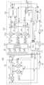
도 1은 본 발명의 일 실시예에 따른 배열 안테나 측정 시스템을 설명하는 개념도이다.
도 2는 도 1의 배열 안테나를 나타내는 개면도이다.
도 3a는 도 1의 배열 안테나 측정 시스템의 합 채널과 방위각 차 채널의 측정을 나타내는 회로도이다.
도 3b는 도 1의 배열 안테나 측정 시스템의 합 채널과 고각 차 채널의 측정을 나타내는 회로도이다.
도 4a는 본 발명의 일 실시예에 따른 배열 안테나 측정 시스템의 합 채널의 이득 측정 결과를 나타낸다.
도 4b는 본 발명의 일 실시예에 따른 배열 안테나 측정 시스템의 합 채널의 위상 측정 결과를 나타낸다.
도 5a는 본 발명의 일 실시예에 따른 배열 안테나 측정 시스템의 방위각 차 채널의 이득 측정 결과를 나타낸다.
도 5b는 본 발명의 일 실시예에 따른 배열 안테나 측정 시스템의 방위각 차 채널의 위상 측정 결과를 나타낸다.
도 6은 본 발명의 다른 실시예에 따른 배열 안테나 측정 시스템을 설명하는 개념도이다.
도 7은 본 발명의 또 다른 실시예에 따른 배열 안테나 측정 시스템을 설명하는 개념도이다.1 is a conceptual diagram explaining an array antenna measurement system according to an embodiment of the present invention.
FIG. 2 is an open view showing the array antenna of FIG. 1.
FIG. 3A is a circuit diagram showing measurement of the sum channel and the azimuth difference channel of the array antenna measurement system of FIG. 1.
FIG. 3B is a circuit diagram showing measurement of the sum channel and the elevation angle difference channel of the array antenna measurement system of FIG. 1.
Figure 4a shows the gain measurement results of the sum channel of the array antenna measurement system according to an embodiment of the present invention.
Figure 4b shows the phase measurement results of the sum channel of the array antenna measurement system according to an embodiment of the present invention.
Figure 5a shows the gain measurement results of the azimuth difference channel of the array antenna measurement system according to an embodiment of the present invention.
Figure 5b shows the phase measurement results of the azimuth difference channel of the array antenna measurement system according to an embodiment of the present invention.
Figure 6 is a conceptual diagram explaining an array antenna measurement system according to another embodiment of the present invention.
Figure 7 is a conceptual diagram explaining an array antenna measurement system according to another embodiment of the present invention.
다양한 밀리미터파 시스템 중 방향탐지 또는 위치 추적에 이용되는 모노펄스 배열 안테나의 경우, 복수의 안테나 및 하이브리드 접합으로 구성되고, 합 채널, 방위각 차 채널, 고각 차 채널 등 복수의 채널을 보유한다. 주요 성능의 평가를 위해서는 채널 별 안테나 성능의 측정이 필요하다.Among various millimeter wave systems, the monopulse array antenna used for direction finding or location tracking consists of multiple antennas and a hybrid junction, and has multiple channels such as a sum channel, azimuth difference channel, and elevation difference channel. To evaluate main performance, it is necessary to measure antenna performance for each channel.
통상적인 모노펄스 수신기 시스템은 3 채널을 구비하며, 합 채널, 방위각 차 채널, 및 고각 차 채널의 특성을 순차적으로 측정하여 분석한다. 그러나, 통상의 시스템은 주파수가 수 GHz로 낮아 시간에 따라 위상이 거의 변하지 않고 안정적이므로 위상 드리프트 등의 문제가 발생하지 않는다.A typical monopulse receiver system has three channels, and the characteristics of the sum channel, azimuth difference channel, and elevation difference channel are sequentially measured and analyzed. However, in a typical system, the frequency is as low as several GHz and the phase is stable with little change over time, so problems such as phase drift do not occur.
그러나 밀리미터파 대역 안테나 성능평가 시스템의 경우는, 능동소자인 고조파 믹서(Harmonic Mixer) 및 전력증폭기(Power Amplifier) 등이 시간에 따라 위상 드리프트(drift) 특성을 가진다. 이러한 능동소자(Active component)에서 위상 드리프트(drift)가 발생하는 대표적 원인은 온도 변화이다.However, in the case of a millimeter wave band antenna performance evaluation system, active elements such as harmonic mixers and power amplifiers have phase drift characteristics over time. The main cause of phase drift in such active components is temperature change.
또한 밀리미터파 대역과 같이 고조파 믹서(Harmonic Mixer)를 사용하는 경우는 RF 신호(RF) 및/또는 국부 발진 신호(LO)를 체배하여 이용하므로, 위상 또한 그 체배수 만큼 곱한 값을 가진다. 그러므로 입력인 RF 신호 및/또는 국부 발진 신호(LO)에 위상 드리프트(drift)가 있는 경우 체배수 만큼 위상 드리프트가 커지므로 저주파의 경우보다 위상 드리프트가 매우 크다.In addition, when a harmonic mixer is used, such as in the millimeter wave band, the RF signal (RF) and/or the local oscillation signal (LO) are multiplied and used, so the phase also has a value multiplied by the multiple. Therefore, if there is a phase drift in the input RF signal and/or the local oscillation signal (LO), the phase drift increases by the multiple, so the phase drift is much larger than in the case of low frequencies.
또한 밀리미터파 대역의 경우 파장의 길이가 mm 단위이다. 이러한 높은 주파수 대역에서는 측정시스템의 진동에 의해 신호의 크기와 위상이 변하며, 특히 위상이 크게 영향을 받는다. 안테나 방사패턴을 원거리장(Far-Field)에서 측정하기 위해서는 방위각 회전을 하면서 안테나의 신호를 측정해야하므로, 방위각의 회전에 따라 발생되는 진동은 피할 수 없으며 이로 인해 위상 변화가 발생한다.Additionally, in the millimeter wave band, the wavelength length is in mm. In these high frequency bands, the size and phase of the signal change due to the vibration of the measurement system, and the phase is especially greatly affected. In order to measure the antenna radiation pattern in the far-field, the signal from the antenna must be measured while rotating the azimuth, so the vibration generated by the rotation of the azimuth cannot be avoided, which causes a phase change.
결론적으로, 단일 채널 시험시 고정된 상태에서 측정하더라도, 진동/온도 변화 등 외부 요인에 의해 위상 측정 결과가 크게 흔들린다. 본 발명의 발명자의 실험결과에 따르면, 100 GHz 대역 단일 채널 측정시, 최초 1분 동안 40도의 위상 드리프트가 발생하므로, 합/차 채널을 각기 측정하는 경우는 측정이 불가능하다.In conclusion, even when measured in a fixed state during a single channel test, the phase measurement results are greatly affected by external factors such as vibration/temperature changes. According to the experimental results of the inventor of the present invention, when measuring a single channel in the 100 GHz band, a phase drift of 40 degrees occurs during the first minute, so measurement is impossible when measuring the sum/difference channels separately.
본 발명은 밀리미터파의 위상 드리프트(drift)를 극복하기 위하여 실질적으로 합 신호와 차 신호를 동시에 측정할 수 있는 다채널 안테나 원거리장 특성 측정 시스템을 제안한다. 구체적으로, 본 발명은 방위각을 변경하면서 배열 안테나의 합 신호와 방위각 차 신호를 동시에 측정한다. 이어서, 본 발명은 방위각을 변경하면서 배열 안테나의 합 신호와 고각 차 신호를 동시에 측정한다. 이에 따라, 합 신호에 대한 차 신호의 위상 드리프는 제거될 수 있다. 방위각 변경에 대하여, 전기적 안정성을 확보하기 위하여, 로터리 조인트와 한 쌍의 다이플렉서가 사용된다. 로터리 조인트와 한 쌍의 다이플렉서는 동일한 경로를 통하여 합 신호와 국부발진 신호를 제공하여 전기적 안정성을 향상시킬 수 있다.The present invention proposes a multi-channel antenna far-field characteristics measurement system that can substantially measure sum and difference signals simultaneously to overcome the phase drift of millimeter waves. Specifically, the present invention simultaneously measures the sum signal and the azimuth difference signal of the array antenna while changing the azimuth. Next, the present invention simultaneously measures the sum signal and elevation difference signal of the array antenna while changing the azimuth angle. Accordingly, the phase drift of the difference signal with respect to the sum signal can be eliminated. To ensure electrical stability for azimuth changes, a rotary joint and a pair of diplexers are used. A rotary joint and a pair of diplexers can improve electrical stability by providing sum signals and local oscillation signals through the same path.
본 발명의 고조파 믹서(harmonic mixer)는 밀리미터파 대역으로, 더 구체적으로, 주파수 체배 RF 신호(n x RF)는 V 밴드(50 to 75 GHz), W 밴드(75 to 110 GHz) 또는 D 밴드(110 to 170 GHz)에서 동작하여 도파관을 입력으로 한다. 고조파(harmonic) 믹서는 출력 포트로 동축 케이블 구조를 사용하고, 출력 신호는 수 MHz에서 수백 MHz의 중간 주파수 대역 신호이다. 고조파 믹서는 10GHz 대역의 국부 발진 신호(LO)를 제공받아 밀리미터파 대역의 주파수 체배 RF 신호(n x RF)와 고조파 주파수 믹싱을 수행하여, 중간 주파수 대역 신호를 동축 케이블 구조의 출력단으로 출력한다.The harmonic mixer of the present invention is a millimeter wave band, more specifically, the frequency multiplied RF signal (n x RF) is V band (50 to 75 GHz), W band (75 to 110 GHz), or D band (110 to 170 GHz) and uses a waveguide as input. The harmonic mixer uses a coaxial cable structure as the output port, and the output signal is an intermediate frequency band signal from several MHz to hundreds of MHz. The harmonic mixer receives the local oscillation signal (LO) in the 10 GHz band, performs harmonic frequency mixing with the frequency multiplied RF signal (n x RF) in the millimeter wave band, and outputs the intermediate frequency band signal to the output terminal of the coaxial cable structure.
송신 안테나에 주파수 체배 RF 신호(n x RF)를 제공하는 송신 벡터 회로망 분석기 확장 모듈은 도파관 구조의 방향성 결합기 및 고조파 믹서를 포함한다. 방향성 결합기는 도파관으로 주파수 체배 RF 신호(n x RF)를 제공받아 송신 안테나에 제공한다. 이러한 도파관 시스템은 정렬, 구조, 온도, 및 진동에 민감하다. 그러나 원거리장 신호를 측정하기 위하여, 안테나 측정 시스템은 수십 미터 이상 연장되고, 송신 마스트 및 수신 마스트도 수 미터 이상이 요구된다.The transmit vector network analyzer extension module, which provides a frequency multiplied RF signal (n x RF) to the transmit antenna, includes a directional coupler and a harmonic mixer in a waveguide structure. The directional coupler receives the frequency multiplied RF signal (n x RF) through a waveguide and provides it to the transmitting antenna. These waveguide systems are sensitive to alignment, geometry, temperature, and vibration. However, in order to measure far-field signals, the antenna measurement system extends tens of meters or more, and the transmitting and receiving masts also require several meters or more.
본 발명의 수신 배열 안테나는 방사된 주파수 체배 RF 신호(n x RF)을 수신하는 도파관 구조의 혼(horn) 안테나 또는 슬롯 안테나 구조를 사용하며, 모노 펄스 비교기는 복수의 하이브리드 접합을 가지며, 하이브리 접합은 도파관을 입력으로 사용하고, 도파관 구조의 출력단에 복수의 RF 채널 신호를 출력한다. 이러한 도파관 시스템은 정렬, 구조, 온도, 및 진동에 민감하다.The receiving array antenna of the present invention uses a horn antenna or slot antenna structure of a waveguide structure for receiving a radiated frequency multiplied RF signal (n x RF), and the monopulse comparator has a plurality of hybrid junctions, and the hybrid junction uses a waveguide as an input and outputs a plurality of RF channel signals to the output terminal of the waveguide structure. These waveguide systems are sensitive to alignment, geometry, temperature, and vibration.
수신 벡터 회로망 분석기 확장 모듈은 RF 채널 신호를 도파관으로 전달받고 복수의 고조파 믹서를 포함한다. 고조파 믹서는 도파관 구조를 사용한다. 이러한 도파관 시스템은 정렬, 구조, 온도, 및 진동에 민감하다. The receive vector network analyzer expansion module receives the RF channel signal through a waveguide and includes a plurality of harmonic mixers. Harmonic mixers use a waveguide structure. These waveguide systems are sensitive to alignment, geometry, temperature, and vibration.
따라서, 도파관 시스템의 안정성과 동일한 전기적 특성을 구현하기 위하여, 송신 벡터 회로망 분석기 확장 모듈 및 수신 벡터 회로망 분석기 확장 모듈은 동일한 구조의 단위 벡터 회로망 분석기 확장 모듈을 사용할 수 있다. 구체적으로, 송신 벡터 회로망 분석기 확장 모듈은 하나의 단위 벡터 회로망 분석기 확장 모듈을 포함할 수 있다. 또한, 수신 벡터 회로망 분석기 확장 모듈은 복수의 단위 벡터 회로망 분석기 확장 모듈을 포함할 수 있다. 각 단위 벡터 회로망 분석기 확장 모듈은 도파관 구조의 방향성 결합기, 방향성 결합기에 결합된 한 쌍의 고조파 믹서를 사용한다. 이에 따라, 복수의 RF 채널 신호(RF CH1, RF CH2, RF CH3) 각각은 단위 벡터 회로망 분석기 확장 모듈을 통하여 동일한 전기적 특성을 구현할 수 있다.Therefore, in order to implement the stability and same electrical characteristics of the waveguide system, the transmission vector network analyzer expansion module and the reception vector network analyzer expansion module can use a unit vector network analyzer expansion module of the same structure. Specifically, the transmit vector network analyzer expansion module may include one unit vector network analyzer expansion module. Additionally, the receive vector network analyzer expansion module may include a plurality of unit vector network analyzer expansion modules. Each unit vector network analyzer expansion module uses a waveguide-structured directional coupler and a pair of harmonic mixers coupled to the directional coupler. Accordingly, each of the plurality of RF channel signals (RF CH1, RF CH2, and RF CH3) can implement the same electrical characteristics through the unit vector network analyzer expansion module.
본 발명은 안테나 특성 측정 시스템에 관한 것으로, 3개 이상의 단위 벡터 회로망 분석기 확장 모듈(VNAX) 및 2개 이상의 포트를 보유하는 로터리 조인트로 구성된다. 배열 안테나의 방사패턴, 원거리장 이득 등의 특성을 원거리에서 측정하기 위해서 로터리 조인트가 방위각 포지셔너에 장착된다.The present invention relates to an antenna characteristic measurement system, which consists of three or more unit vector network analyzer expansion modules (VNAX) and a rotary joint having two or more ports. In order to measure characteristics such as the radiation pattern and far-field gain of the array antenna from a distance, a rotary joint is mounted on the azimuth positioner.
이하, 첨부한 도면들을 참조하여 본 발명의 바람직한 실시예들을 상세히 설명하기로 한다. 그러나, 본 발명은 여기서 설명되어지는 실시예들에 한정되지 않고 다른 형태로 구체화될 수도 있다. 오히려, 여기서 소개되는 실시예는 개시된 내용이 철저하고 완전해질 수 있도록 그리고 당업자에게 본 발명의 사상이 충분히 전달될 수 있도록 하기 위해 제공되어지는 것이다. 도면들에 있어서, 구성요소는 명확성을 기하기 위하여 과장되어진 것이다. 명세서 전체에 걸쳐서 동일한 참조번호로 표시된 부분들은 동일한 구성요소들을 나타낸다. Hereinafter, preferred embodiments of the present invention will be described in detail with reference to the attached drawings. However, the present invention is not limited to the embodiments described herein and may be embodied in other forms. Rather, the embodiments introduced herein are provided so that the disclosure will be thorough and complete and so that the spirit of the invention can be fully conveyed to those skilled in the art. In the drawings, elements are exaggerated for clarity. Parts indicated with the same reference numerals throughout the specification represent the same elements.
도 1은 본 발명의 일 실시예에 따른 배열 안테나 측정 시스템을 설명하는 개념도이다.1 is a conceptual diagram explaining an array antenna measurement system according to an embodiment of the present invention.
도 2는 도 1의 배열 안테나를 나타내는 개면도이다.FIG. 2 is an open view showing the array antenna of FIG. 1.
도 3a는 도 1의 배열 안테나 측정 시스템의 합 채널과 방위각 차 채널의 측정을 나타내는 회로도이다.FIG. 3A is a circuit diagram showing measurement of the sum channel and the azimuth difference channel of the array antenna measurement system of FIG. 1.
도 3b는 도 1의 배열 안테나 측정 시스템의 합 채널과 고각 차 채널의 측정을 나타내는 회로도이다.FIG. 3B is a circuit diagram showing measurement of the sum channel and the elevation angle difference channel of the array antenna measurement system of FIG. 1.
도 1 내지 도 3을 참조하면, 배열 안테나 측정 시스템(100)은, 벡터 회로망 분석기(110), 송신 벡터 회로망 분석기 확장 모듈(120), 송신 안테나(130), 수신 배열 안테나(140), 수신 벡터 회로망 분석기 확장 모듈(150), 및 로터리 조인트(180)를 포함한다.1 to 3, the array antenna measurement system 100 includes a
벡터 회로망 분석기(110)는 RF 신호(RF) 및 국부 발진 신호(LO)를 출력한다. 송신 벡터 회로망 분석기 확장 모듈(120)은 상기 벡터 회로망 분석기(110)에서 상기 RF 신호를 제공받아 주파수 체배하여 주파수 체배 RF 신호(n x RF)를 송신 안테나(130)에 전달하고, 상기 주파수 체배 RF 신호(n x RF)와 상기 국부 발진 신호(LO)를 사용하여 다운 컨버젼하여 기준 중간 주파수 신호(REF IF)를 생성하고, 상기 기준 중간 주파수 신호(REF IF)를 상기 벡터 회로망 분석기(110)에 제공한다. 수신 배열 안테나(140)는 상기 송신 안테나(130)에서 방사된 주파수 체배 RF 신호(n x RF)를 전달받아 복수의 RF 채널 신호(RF CH1, RF CH2, RF CH3)를 출력한다. 수신 벡터 회로망 분석기 확장 모듈(150)은 상기 복수의 RF 채널 신호(RF CH1, RF CH2)와 상기 국부 발진 신호(LO)를 사용하여 다운 컨버젼하여 복수의 테스트 중간 주파수 신호들(TE1 IF, TE2 IF, TE3 IF)을 각각 생성한다. 로터리 조인트(180)는 상기 국부 발진 신호(LO)를 수신 벡터 회로망 분석기 확장 모듈(150)에 전달하고 상기 복수의 테스트 중간 주파수 신호들(TE1 IF, TE2 IF, TE3 IF)을 상기 벡터 회로망 분석기(110)에 동일한 경로를 통하여 제공한다.The
벡터 회로망 분석기(110)는 RF 신호(RF) 및 국부 발진 신호(LO)를 출력할 수 있다. 벡터 회로망 분석기(110)는 RF 신호(RF)와 국부발진 신호(LO)와 같이 수신 배열 안테나의 특성을 측정하는 데에 필요한 신호들을 생성할 수 있다. 상기 국부 발진 신호(LO)의 주파수는 수 GHz 내지 수십 GHz 대역일 수 있다. 상기 RF 신호(RF)의 주파수는 10 GHz 대역일 수 있다. 벡터 회로망 분석기(110)는 복수의 수신 채널을 구비할 수 있다. 상기 수신 채널들은 기준 중간 주파수 신호(REF IF), 보조 중간 주파수 신호(AUX IF), 제1 테스트 중간 주파수 신호(TE1 IF), 제2 테스트 중간 주파수 신호(TE2 IF)일 수 있다.The
또는 상기 수신 채널들은 기준 중간 주파수 신호(REF IF), 보조 중간 주파수 신호(AUX IF), 제1 테스트 중간 주파수 신호(TE1 IF), 제3 테스트 중간 주파수 신호(TE3 IF)일 수 있다.Alternatively, the receiving channels may be a reference intermediate frequency signal (REF IF), an auxiliary intermediate frequency signal (AUX IF), a first test intermediate frequency signal (TE1 IF), and a third test intermediate frequency signal (TE3 IF).
상기 벡터 회로망 분석기(110)는 기준 중간 주파수 신호(REF IF)와 제1 테스트 중간 주파수 신호(TE1 IF)를 사용하여 배열 안테나의 합 신호 특성을 분석할 수 있다. 상기 벡터 회로망 분석기(110)는 기준 중간 주파수 신호(REF IF)와 제2 테스트 중간 주파수 신호(TE2 IF)를 사용하여 배열 안테나의 방위각 차 신호 특성을 분석할 수 있다.The
상기 벡터 회로망 분석기(110)의 신호들은 동축 케이블을 통해 송신 벡터 회로망 분석기 확장 모듈(120), 제2 다이플렉서(168) 및 수신 벡터 회로망 분석기 확장 모듈(150) 등에 연결될 수 있다. 상기 동축 케이블은 꼬임, 온도, 및 진동 등에 의하여 위상 드리프를 발생시킬 수 있다. 따라서, 위상 드리프트를 최소화하기 위하여, 수신 벡터 회로망 분석기 확장 모듈(150)에 제공되는 국부 발진 신호(LO)와 합 신호는 동일한 경로 (또는 동일한 동축 케이블)을 통하여 제공될 수 있다. 또한, 국부 발진 신호(LO)와 합 신호의 분리 및 결합을 위하여, 제1 다이플렉서(158)와 제2 다이플레서(168)가 사용될 수 있다.Signals from the
증폭기(112)는 상기 벡터 회로망 분석기(110)의 상기 RF 신호(RF)를 증폭하여 상기 송신 벡터 회로망 분석기 확장 모듈(112)에 제공할 수 있다. 상기 증폭기(112)는 상기 벡터 회로망 분석기(110)에 인접하게 배치될 수 있다.The
신호 분배기(162)는 상기 벡터 회로망 분석기(110)의 국부 발진 신호(LO)를 균등하게 분기할 수 있다. 제1 저노이즈 증폭기(164) 및 제2 저노이즈 증폭기(166)는 상기 신호 분배기(162)에서 분배된 국부 발진 신호(LO)를 각각 증폭할 수 있다.The
상기 제2 저노이즈 증폭기(166)는 상기 제2 다이플렉서(168)와 인접하게 배치될 수 있다. 상기 제1 저노이즈 증폭기(162) 및 상기 제2 저노이즈 증폭기(164)는 신호 분배기(162)에 대하여 대칭적을 배치될 수 있다. 상기 신호 분배기와 상기 제2 저노이즈 증폭기 사이의 전송선의 길이는 상기 송신 안테나(130)와 상기 수신 배열 안테나(140) 사이의 거리(d)의 반일 수 있다. 상기 신호 분배기162)와 상기 제1 저노이즈 증폭기(164) 사이의 전송선의 길이는 상기 송신 안테나(130)와 상기 수신 배열 안테나(140) 사이의 거리의 반일 수 있다. 상기 송신 안테나(130)와 상기 수신 배열 안테나(140) 사이의 거리(d)는 원거리장 측정을 위하여 수십 미터일 수 있다. 상기 제1 저노이즈 증폭기(164) 및 상기 제2 저노이즈 증폭기(166)는 광대역 저노이즈 증폭기일 수 있다. 주파수 대역은 수 GHz 내지 수십 GHz일 수 있다.The second
상기 송신 벡터 회로망 분석기 확장 모듈(120)은, 상기 벡터 회로망 분석기(110)의 상기 RF 신호(RF)를 제공받아 주파수 체배하여 주파수 체배 RF 신호(n x RF)를 출력하는 체배기(122); 상기 주파수 채배 RF 신호(n x RF)를 전달받아 상기 송신 안테나(130)에 전달하는 방향성 결합기(124); 상기 방향성 결합기(124)의 포트에 결합되고 상기 주파수 채배 RF 신호(n x RF)와 상기 국부 발진 신호(LO)를 사용하여 다운 컨버팅하여 상기 기준 중간 주파수 신호(REF IF)를 출력하는 제1 고조파 믹서(126); 및 상기 방향성 결합기(124)의 포트에 결합되고 상기 송신 안테나에서 반사된 주파수 채배 RF 신호(n x RF)와 상기 국부 발진 신호(LO)를 사용하여 다운 컨버팅하여 상기 보조 중간 주파수 신호(AUX IF)를 출력하는 제2 고조파 믹서(128);를 포함할 수 있다.The transmission vector network
상기 기준 중간 주파수 신호(REF IF) 및 상기 보조 중간 주파수 신호(AUX IF)의 주파수는 100 MHz 대역일 수 있다. The frequencies of the reference intermediate frequency signal (REF IF) and the auxiliary intermediate frequency signal (AUX IF) may be in the 100 MHz band.
상기 체배기(122)는 주파수를 체배할 수 있으며, 상기 RF 신호(RO)의 6배의 주파수를 체배할 수 있다. 상기 체배기(122)의 출력은 도파관일 수 있다.The
상기 방향성 결합기(124)는 도파관 구조의 방향성 결합기이고, 진행파 전력 측정용 포트와 반사파 전력 측정용 포트를 포함하는 4 포트 소자일 수 있다.The
상기 제1 고조파 믹서(126)는 상기 송신 안테나로 진행하는 주파수 채배 RF 신호(n x RF)와 상기 국부 발진 신호(LO)를 제공받아 상기 국부 발진 신호(LO)의 고주파와 상기 주파수 채배 RF 신호(n x RF)을 믹싱하여 저주파 성분으로 상기 기준 주파수 신호(REF IF)를 출력할 수 있다. 상기 제1 고조파 믹서(126)는 입력으로 도파관을 사용하고, 출력으로 동축 케이블을 사용할 수 있다.The first
상기 제2 고주파 믹서(128)는 상기 송신 안테나(130)에서 반사된 주파수 채배 RF 신호(n x RF)와 상기 국부 발진 신호(LO)를 제공받아 상기 국부 발진 신호(LO)의 고주파와 상기 주파수 채배 RF 신호(n x RF)을 믹싱하여 저주파 성분으로 상기 보조 주파수 신호(AUX IF)를 출력할 수 있다. 상기 제2 고조파 믹서(128)는 입력으로 도파관을 사용하고, 출력으로 동축 케이블을 사용할 수 있다. 상기 제1 고조파 믹서(126), 제2 고주파 믹서(128), 및 상기 방향성 결합기(124)는 하나의 단위 벡터 회로망 분석기 확장 모듈을 형성할 수 있다.The second
송신 안테나(130)는 상기 방향성 결합기(124)를 진행하는 상기 주파수 체배 RF 신호(n x RF)를 제공받아 방사하는 안테나일 수 있다. 상기 송신 안테나(130)는 혼(horn) 안테나, 또는 슬롯 안테나일 수 있다.The transmitting
송신 마스트(182)는 상기 송신 벡터 회로망 분석기 확장 모듈(120) 및 송신 안테나(130)를 지지할 수 있다. 상기 송신 마스트(182)의 높이는 수 미터일 수 있다.The transmission mast 182 may support the transmission vector network
수신 배열 안테나(140)는 모노펄스 배열 안테나일 수 있다. 수신 배열 안테나(140)는 소정의 간격으로 2차원적으로 배열된 4개의 혼 안테나일 수 있다. 각각의 안테나는 혼 안테나 또는 슬롯 안테나일 수 있다.The receiving
모노펄스 배열 안테나는 각각의 개구면을 가진 배열 안테나(A‘, B’, C‘, D’)와 각 안테나의 예비 RF 신호들(A, B, C, D)을 연산하여 합/차 신호를 출력하는 모노펄스 비교부(146)를 포함한다.The monopulse array antenna generates a sum/difference signal by calculating the array antennas (A', B', C', D') with each aperture and the preliminary RF signals (A, B, C, D) of each antenna. It includes a
상기 수신 배열 안테나(140)는, 상기 방사된 주파수 체배 RF 신호(n x RF)를 수신하여 복수의 예비 RF 신호들(A, B, C, D)을 출력하는 배열 안테나(142); 및 상기 예비 RF 신호들(A, B, C, D)을 연산하여 상기 RF 채널 신호(RF CH1, RF CH2, RF CH3)를 생성하는 모노펄스 비교기(146)를 포함한다. 상기 모노펄스 비교기(146)는 4 개의 하이브리드 접합(146a~146d)을 포함한다. 상기 하이브리드 접합의 입력과 출력은 도파관이다. 상기 RF 채널 신호(RF CH1, RF CH2, RF CH3)는 각각 합 채널 신호, 방위각 차 신호, 및 고각차 신호이다. 합(Sum), 방위각 차(Az: Azimuth Difference), 고각 차(El: Elevation Difference) 신호들의 크기와 위상을 측정하고 처리하면, 대상표적을 추적할 수 있다.The receiving
제1 안테나(A’)는 상기 방사된 주파수 체배 RF 신호(n x RF)를 수신하여 제1 예비 RF 신호(A)를 출력한다. 제2 안테나(B‘)는 상기 제1 안테나와 소정의 간격으로 이격되어 배치되고 상기 방사된 주파수 체배 RF 신호(n x RF)를 수신하여 제2 예비 RF 신호(B)를 출력한다. 제3 안테나(C’)는 상기 제1 안테나와 소정의 간격으로 이격되어 배치되고 상기 방사된 주파수 체배 RF 신호(n x RF)를 수신하여 제3 예비 RF 신호(C)를 출력한다. 제4 안테나(D’)는 상기 제2 안테나와 소정의 간격으로 이격되어 배치되고 상기 방사된 주파수 체배 RF 신호(n x RF)를 수신하여 제4 예비 RF 신호(D)를 출력한다.The first antenna (A') receives the radiated frequency multiplied RF signal (n x RF) and outputs a first preliminary RF signal (A). The second antenna (B') is disposed at a predetermined distance from the first antenna, receives the radiated frequency multiplied RF signal (n x RF), and outputs a second preliminary RF signal (B). The third antenna (C') is arranged to be spaced apart from the first antenna at a predetermined interval and receives the radiated frequency multiplied RF signal (n x RF) and outputs a third preliminary RF signal (C). The fourth antenna (D') is disposed at a predetermined distance from the second antenna, receives the radiated frequency multiplied RF signal (n x RF), and outputs a fourth preliminary RF signal (D).
제1 하이브리드 접합(146a)은 상기 제1 예비 RF 신호(A) 및 상기 제2 예비 RF 신호(B)를 합 및 차 연산하여 제1 합 RF 신호(A+B) 및 제1 차 RF 신호(A-B)를 각각 출력한다. The
제2 하이브리드 접합(146b)은 상기 제3 예비 RF 신호(C) 및 상기 제4 예비 RF 신호(D)를 합 및 차 연산하여 제2 합 RF 신호(C+D) 및 제2 차 RF 신호(C-D)를 각각 출력한다.The second
제3 하이브리드 접합(146c)는 상기 제1 하이브리드 접합(hybrid junction)의 제1 합 신호(A+B)와 상기 제2 하이브리드 접합(hybrid junction)의 제2 합 신호(C+D)를 합 연산 및 차 연산하여 합 신호(A+B+C_D) 및 방위각 차 신호(A+B-C-D)를 각각 출력한다. 합 신호(A+B+C_D)는 제1 RF 채널 신호(RF CH1)이다. 방위각 차 신호(A+B-C-D)는 제2 RF 채널 신호(RF CH2)이다.The third
제4 하이브리드 접합(146d)는 상기 제1 하이브리드 접합(hybrid junction)의 제1 차 신호(A-B)와 상기 제2 하이브리드 접합(hybrid junction)의 제2 차 신호(C-D)를 합 연산하여 고각 차 신호(A+C-B-D)를 출력한다. 상기 제4 하이브리드 접합(146d)의 차 연산 신호는 더머로드(DL)에 제공된다. 고각 차 신호(A+C-B-D)는 제3 RF 채널 신호(RF CH3)이다.The
합 채널에서 출력되는 합(Sum) 신호((A+B)+(C+D))는 송신 안테나(130)로부터 출력되는 전자파에 반응하여 크기와 위상을 가지는 신호를 출력한다. 따라서, 하나의 안테나로 볼 수 있다. 또한, 방위각(Az) 차 신호((A+B)-(C+D))는 하나의 안테나로 볼 수 있다. 고각(El) 차 신호((A+C)-(B+D))는 하나의 안테나로 볼 수 있다. 모노펄스 배열 안테나는 합/차 안테나의 크기 및 위상 방사패턴 특성을 이용하여 위치를 추적한다. 그러므로 합/차 안테나들의 크기 및 위상 방사패턴이 설계치를 만족하는지를 판별하는 것이 매우 중요하며 이를 정확히 측정하기 위한 시스템이 필요하다.The Sum signal ((A+B)+(C+D)) output from the sum channel outputs a signal with size and phase in response to electromagnetic waves output from the transmitting
두개의 채널을 보유한 안테나 측정시스템이 설명된다. 밀리미터파를 이용하는 안테나 시스템의 특성을 측정하기 위해서는 송신마스트(182) 위에 설치된 송신 벡터 회로망 분석기 확장 모듈(120)의 RF 출력단에 이득 등의 특성이 이미 파악된 송신 안테나(130)가 설치된다. 상기 송신 안테나(130)는 송신 신호 또는 주파수 채배 RF 신호(n x RF)를 방사한다. 송신 벡터 회로망 분석기 확장 모듈(120)에서 출력되는 기준 중간 주파수 신호(REF IF)와 보조 중간 주파수 신호(AUX IF)는 벡터 회로망 분석(110)에 연결된다.An antenna measurement system with two channels is described. In order to measure the characteristics of an antenna system using millimeter waves, a
수신 배열 안테나(140) 및 송신 벡터 회로망 분석기 확장 모듈(120)은 수신 마스트(184)에 설치된다. 수신 마스트(184)의 높이는 수 미터일 수 있다. 상기 수신 마스트(184)는 방위각 방향으로 회전할 수 있다.The receiving
특성평가 대상인 수신 배열 안테나(140)는 수신 벡터 회로망 분석기 확장 모듈(150)에 연결된다. 수신 배열 안테나(140)는 합, 방위각 차, 고각 차의 신호를 출력한다. 수신 벡터 회로망 분석기 확장 모듈(150)은 수신 배열 안테나(140)의 출력 신호들을 처리하여 테스트 중간 주파수 신호들(TE1 IF, TE2 IF, TE3 IF)을 벡터 회로망 분석(110)에 제공한다. 벡터 회로망 분석기(110)는 방위각을 변경하면서 합 신호와 차 신호를 측정한다. 이들 신호들을 이용하여 방위각에 따른 수신 배열 안테나의 특성이 측정된다.The receiving
포지셔너(172)는 상기 수신 마스크(184)의 높이와 방위각을 제어할 수 있다. 상기 포지셔너(172)는 방위각 스테이지(173)을 구비하고 있고, 상기 방위각 스테이지(173)에 로터리 조인트(180)가 설치되어 있다. 로터리 조인트(180)는 방위각 스테이지(173)의 방위각 회전 운동에 대하여 케이블의 꼬임을 방지한다. 로터리 조인트(180)는 접촉 방식 또는 비접촉 방식으로 동작할 수 있다.The positioner 172 can control the height and azimuth of the receiving mask 184. The positioner 172 is equipped with an azimuth stage 173, and a rotary joint 180 is installed on the azimuth stage 173. The rotary joint 180 prevents twisting of the cable with respect to the azimuth rotational movement of the azimuth stage 173. The rotary joint 180 may operate in a contact or non-contact manner.
방위각 스테이지(173)는 수신 마스트(184)를 지지하고 방위각 회전 운동을 제공할 수 있다. 상기 수신 마스트(183)의 높이는 수 미터일 수 있다. 상기 수신 마스트(183)는 상기 수신 벡터 회로망 분석기 확장 모듈(150) 및 상기 수신 배열 안테나(140)를 지지하는 방위각을 조절할 수 있다. 상기 방위각 스테이지(173)는 회전하여 상기 수신 배열 안테나(140)의 방위각을 조절할 수 있다.Azimuth stage 173 may support receiving mast 184 and provide azimuthal rotational motion. The height of the receiving mast 183 may be several meters. The receiving mast 183 can adjust the azimuth angle supporting the receiving vector network
DC 전원(169)은 방위각 스테이지(173) 상에 배치될 수 있다. 상기 DC 전원(169)은 상기 수신 마스트(184)를 따라 연장되어 상기 수신 벡터 회로망 분석기 확장 모듈(150)에 전력을 공급할 수 있다.A DC power source 169 may be placed on the azimuth stage 173. The DC power source 169 may extend along the receiving mast 184 to power the receiving vector network
상기 수신 벡터 회로망 분석기 확장 모듈(150)은, 복수의 고조파 믹서들(152a, 152b)과 제1 다이플렉서(158)를 포함할 수 있다. 복수의 고조파 믹서들(152a, 152b) 각각은 상기 RF 채널 신호들(RF CH1, RF CH2, RF CH3) 중의 하나와 상기 국부 발진 신호(LO)를 제공받아 다운 컨버팅하여 상기 테스트 중간 주파수 신호들(TE1 IF, TE2 IF, TE3 IF)을 각각 생성할 수 있다. 제1 다이플렉서(158)는 상기 로터리 조인트(180)의 상기 국부 발진 신호(LO)를 상기 고조파 믹서들(152a, 152b) 각각에 전달하고 상기 테스트 중간 주파수 신호들(TE1 IF, TE2 IF, TE3 IF) 중에서 하나를 동일한 경로를 통하여 상기 로터리 조인트(180)에 전달할 수 있다.The receive vector network
복수의 고조파 믹서들(152a,152b)은 입력으로 도파관을 사용하고 출력으로 동축 케이블을 사용할 수 있다. 제1 고조파 믹서(152a)는 제1 RF 채널 신호(RF CH1)를 도파관으로 제공받고 동축 케이블을 통하여 국부 발진 신호(LO)를 제공받아, 국부 발진 신호의 고조파와 제1 RF 채널 신호(RF CH1)을 믹싱하여 제1 상기 테스트 중간 주파수 신호(TE1 IF)를 동축 케이블로 출력할 수 있다.The plurality of
제2 고조파 믹서(154)는 제2 RF 채널 신호(RF CH2)를 도파관으로 제공받고 동축 케이블을 통하여 국부 발진 신호(LO)를 제공받아, 국부 발진 신호(LO)의 고조파와 제2 RF 채널 신호(RF CH2)을 믹싱하여 제2 상기 테스트 중간 주파수 신호(TE2 IF)를 동축 케이블로 출력할 수 있다.The second harmonic mixer 154 receives the second RF channel signal (RF CH2) through a waveguide and the local oscillation signal (LO) through a coaxial cable, and mixes the harmonics of the local oscillation signal (LO) and the second RF channel signal. (RF CH2) can be mixed to output the second test intermediate frequency signal (TE2 IF) through a coaxial cable.
신호 분배기(156)는 국부 발진 신호(LO)을 분기하여 고조파 믹서들(152,154)에 각각 제공할 수 있다. 국부 발진 신호(LO)의 세기가 약한 경우, 신호 분배기(156)의 입력단에 저노이즈 증폭기 및 감쇠기가 추가로 장착되어, 신호의 크기를 조절할 수 있다.The
상기 제1 다이플렉서(158)는 상기 제1 테스트 중간 주파수 신호(TE1 IF)를 제1 포트(P1)로 제공받아 제2 포트(P2)로 출력하고, 상기 국부 발진 신호(LO)를 상기 제2 포트(P2)로 입력받아 제3 포트(P3)로 출력한다. 상기 제1 다이플렉서의 제3 포토(P3)를 통하여 제공된 상기 국부 발진 신호(LO)는 신호 분배기(156)에 의하여 분기되어 상기 제1 고조파 믹서(152) 및 상기 제2 고조파 믹서(154)에 각각 제공될 수 있다.The
로터리 조인트(180)의 제1 채널(180a)은 상기 제1 다이플렉서(158)와 상기 제2 다이플렉서(168) 사이에 전기적 연결을 수행할 수 있다. 상기 로터리 조인트(180)는 회전자와 고정자를 포함할 수 있다. 상기 회전자는 상기 수신 마스트와 함께 회전할 수 있다. 고정자는 상기 방위각 스테이지에 고정될 수 있다.The
상기 로터리 조인트(180)는 제1 채널(180a)로 상기 국부 발진 신호(LO) 및 상기 제1 테스트 중간 주파수 신호(TE1 IF)를 전달하고 제2 채널(180b)로 상기 제2 테스트 중간 주파수 신호(TE2 IF)를 전달할 수 있다. 상기 로터리 조인트(180)는 동축 케이블 구조일 수 있다. 상기 로터리 조인트(180)의 제1 채널(180a)은 고주파 채널이고 상기 로터리 조인트의 제2 채널(180b)은 저주파 채널일 수 있다. 즉, 상기 국부 발진 신호(LO) 및 상기 제1 테스트 중간 주파수 신호(TE1 IF)는 로터리 조인트의 제1 채널(1)에 연결되고, 상기 제2 테스트 중간 주파수 신호(TE2 IF)은 로터리 조인트의 제2 채널(180b)에 연결될 수 있다.The rotary joint 180 transmits the local oscillation signal LO and the first test intermediate frequency signal TE1 IF to the
제2 다이플렉서(158)는 상기 벡터 회로망 분석기(110)의 상기 국부 발진신호(LO)를 제1 포트(P1)로 제공받아 제2 포트(P2)로 출력하고 상기 제1 다이플렉서(158)의 제2 포트(P2)의 상기 제1 테스트 중간 주파수 신호(TE1 IF)를 제2 포트(P2)로 제공받아 제3 포트(P3)를 통하여 상기 벡터 회로망 분석기(110)에 제공한다.The
제1 다이플레서(158), 로터리 조인트의 제1 채널(180a), 및 제2 다이플렉서(168)는 국부 발진신호(LO)와 상기 제1 테스트 중간 주파수 신호(TE1 IF 또는 합 신호)를 하나의 동축 케이블(또는 전송선)을 통하여 전달할 수 있다. 이에 따라, 국부 발진신호(LO)와 상기 제1 테스트 중간 주파수 신호(TE1 IF 또는 합 신호) 사이의 위상 드리프트는 최소화될 수 있다.The
제어부(170)는 벡터 회로망 분석기(110)와 포지셔너(172)를 제어할 수 있다. 이에 따라, 벡터 회로망 분석기(110)는 특정 방위각에서 제1 상기 테스트 중간 주파수 신호(TE1 IF)와 제2 상기 테스트 중간 주파수 신호(TE2 IF)를 실질적으로 동시에 측정할 수 있다. 상기 벡터 회로망 분석기(110)는 상기 기준 중간 주파수 신호(REF ID)에 대하여 상기 제1 테스트 중간 주파수 신호(TE1 IF) 및 상기 제2 테스트 중간 주파수 신호(TE IF)의 산란 매트릭스를 산출할 수 있다. 이에 따라, 상기 수신 배열 안테나의 특성(이득 및 위상)이 분석될 수 있다. 상기 산란 매트릭스는 상기 수신 배열 안테나의 방위각 별로 산출될 수 있다.The control unit 170 can control the
이어서, 제어부(170)는 포지셔너(172)를 제어하여 수신 배열 안테나(140)의 방위각을 조절한 후, 다시 벡터 회로망 분석기(110)는 변화된 방위각에서 제1 상기 테스트 중간 주파수 신호(TE1 IF)와 제2 상기 테스트 중간 주파수 신호(TE2 IF)를 실질적으로 동시에 측정할 수 있다. 이러한 동작은 측정하고자 하는 방위각 범위에 대하여 순차적으로 수행될 수 있다.Subsequently, the control unit 170 controls the positioner 172 to adjust the azimuth of the receiving
제1 RF 채널 신호(RF CH1)와 제2 RF 채널 신호(RF CH2)에 대한 측정이 완료된 경우, 제1 RF 채널 신호(RF CH1)와 제3 RF 채널 신호(RF CH3)에 대한 측정이 수행될 수 있다. 제2 RF 채널 신호(RF CH2)를 제3 RF 채널 신호(RF CH3)로 변경하여 측정하기 위하여, 도파관의 체결용 볼트를 풀어 다른 채널의 도파관에 연결할 수 있다.When the measurement of the first RF channel signal (RF CH1) and the second RF channel signal (RF CH2) is completed, the measurement of the first RF channel signal (RF CH1) and the third RF channel signal (RF CH3) is performed. It can be. In order to change the second RF channel signal (RF CH2) to the third RF channel signal (RF CH3) and measure it, the fastening bolt of the waveguide can be loosened and connected to the waveguide of another channel.
제1 RF 채널 신호(RF CH1)와 제2 RF 채널 신호(RF CH2)는 동시에 측정되므로, 이들 신호 간의 위상 드리프트는 무시될 수 있다. 또한, 제1 RF 채널 신호(RF CH1)와 제3 RF 채널 신호(RF CH3)는 동시에 측정되므로, 이들 신호 간의 위상 드리프트는 무시될 수 있다.Since the first RF channel signal (RF CH1) and the second RF channel signal (RF CH2) are measured simultaneously, the phase drift between these signals can be ignored. Additionally, since the first RF channel signal (RF CH1) and the third RF channel signal (RF CH3) are measured simultaneously, the phase drift between these signals can be ignored.
제1 RF 채널 신호(RF CH1, 합 채널)에서 출력되는 신호는 (A+B)+(C+D)이다. 이 합 채널 신호를 구성하는 합 신호 안테나는 이미 이득을 알고 있는 송신 안테나를 이용하면, 이득과 위상을 측정할 수 있다. The signal output from the first RF channel signal (RF CH1, sum channel) is (A+B)+(C+D). The gain and phase of the sum signal antenna constituting this sum channel signal can be measured by using a transmission antenna whose gain is already known.
제2 RF 채널 신호(RF CH2, 방위각 차 채널)에서 출력되는 신호는 (A+B)-(C+D)이다. 이 방위각 차 채널 신호를 구성하는 방위각 차신호 안테나는 이미 이득을 알고 있는 송신 안테나를 이용하면, 이득과 위상을 측정할 수 있다.The signal output from the second RF channel signal (RF CH2, azimuth difference channel) is (A+B)-(C+D). The gain and phase of the azimuth difference signal antenna constituting this azimuth difference channel signal can be measured by using a transmission antenna whose gain is already known.
또한, 제3 RF 채널 신호(RF CH3, 고각 차 채널)에서 출력되는 신호는 (A+C)-(B+D)이다. 이 고 차 채널 신호를 구성하는 고각 차신호 안테나는 이미 이득을 알고 있는 송신 안테나를 이용하면, 이득과 위상을 측정할 수 있다. 이 측정 데이터를 이용하여 합 신호와 차 신호 사이의 상대이득 및 상대 각도의 측정이 가능하다.Additionally, the signal output from the third RF channel signal (RF CH3, elevation difference channel) is (A+C)-(B+D). The gain and phase of the high-angle difference signal antenna that constitutes this high-order channel signal can be measured by using a transmission antenna whose gain is already known. Using this measurement data, it is possible to measure the relative gain and relative angle between the sum signal and the difference signal.
본 발명의 안테나 측정시스템은 합 신호와 방위각 차신호를 거의 동시에 측정하므로 시간 지연에 따른 위상 편차(phase drift)없이 측정할 수 있다. 위와 같이 합/방위각 차 신호를 측정하여 이득 및 위상차를 측정한 후, 연결을 변경하여 합/고각 차 신호를 측정하면, 전체 모노펄스 배열 안테나의 이득 및 위상 특성을 측정할 수 있다. The antenna measurement system of the present invention measures the sum signal and the azimuth difference signal almost simultaneously, so measurement can be performed without phase drift due to time delay. After measuring the gain and phase difference by measuring the sum/azimuth difference signal as above, and then changing the connection to measure the sum/elevation difference signal, the gain and phase characteristics of the entire monopulse array antenna can be measured.
도 4a는 본 발명의 일 실시예에 따른 배열 안테나 측정 시스템의 합 채널의 이득 측정 결과를 나타낸다.Figure 4a shows the gain measurement results of the sum channel of the array antenna measurement system according to an embodiment of the present invention.
도 4b는 본 발명의 일 실시예에 따른 배열 안테나 측정 시스템의 합 채널의 위상 측정 결과를 나타낸다.Figure 4b shows the phase measurement results of the sum channel of the array antenna measurement system according to an embodiment of the present invention.
도 4a 및 도 4b를 참조하면, 합 채널에서 방위각에 따른 이득이 표시된다. 합 채널에서 방위각에 따른 위상이 표시된다. 원거리장 이득 측정 결과는 근거리장 측정 결과와 유사하다. 원거리장 측정(Far-field Measurement)은 비교용으로 측정한 근접전계(Near-field Measurement) 측정 결과와 잘 일치한다.Referring to FIGS. 4A and 4B, the gain according to azimuth in the sum channel is displayed. In the sum channel, the phase according to azimuth is displayed. The far-field gain measurement results are similar to the near-field measurement results. The far-field measurement matches well with the near-field measurement results measured for comparison.
도 5a는 본 발명의 일 실시예에 따른 배열 안테나 측정 시스템의 방위각 차 채널의 이득 측정 결과를 나타낸다.Figure 5a shows the gain measurement results of the azimuth difference channel of the array antenna measurement system according to an embodiment of the present invention.
도 5b는 본 발명의 일 실시예에 따른 배열 안테나 측정 시스템의 방위각 차 채널의 위상 측정 결과를 나타낸다.Figure 5b shows the phase measurement results of the azimuth difference channel of the array antenna measurement system according to an embodiment of the present invention.
도 5a 및 도 5b를 참조하면, 방위각 차 채널에서 방위각에 따른 이득이 표시된다. 방위각 차 채널에서 방위각에 따른 위상이 표시된다. 원거리장 이득 측정 결과는 근거리장 측정 결과와 유사하다. 원거리장 측정(Far-field Measurement)은 비교용으로 측정한 근접전계(Near-field Measurement) 측정 결과와 잘 일치한다.Referring to FIGS. 5A and 5B, gain according to azimuth angle is displayed in the azimuth difference channel. In the azimuth difference channel, the phase according to azimuth is displayed. The far-field gain measurement results are similar to the near-field measurement results. The far-field measurement matches well with the near-field measurement results measured for comparison.
도 6은 본 발명의 다른 실시예에 따른 배열 안테나 측정 시스템을 설명하는 개념도이다.Figure 6 is a conceptual diagram explaining an array antenna measurement system according to another embodiment of the present invention.
도 6을 참조하면, 배열 안테나 측정 시스템(200)은, 벡터 회로망 분석기(110), 송신 벡터 회로망 분석기 확장 모듈(120), 송신 안테나(130), 수신 배열 안테나(140), 수신 벡터 회로망 분석기 확장 모듈(250), 로터리 조인트(180)를 포함한다.Referring to FIG. 6, the array
벡터 회로망 분석기(110)는 RF 신호(RF) 및 국부 발진 신호(LO)를 출력한다. 송신 벡터 회로망 분석기 확장 모듈(120)은 상기 벡터 회로망 분석기(110)에서 상기 RF 신호(RF)를 제공받아 주파수 체배하여 주파수 체배 RF 신호(n x RF)를 송신 안테나(130)에 전달하고, 상기 주파수 체배 RF 신호(n x RF)와 상기 국부 발진 신호(LO)를 사용하여 다운 컨버젼하여 기준 중간 주파수 신호(REF IF)를 생성하고, 상기 기준 중간 주파수 신호(REF IF)를 상기 벡터 회로망 분석기(110)에 제공한다. 수신 배열 안테나(140)는 상기 송신 안테나(130)에서 방사된 주파수 체배 RF 신호(n x RF)를 전달받아 복수의 RF 채널 신호(RF CH1, RF CH2, RF CH3)를 출력한다. 수신 벡터 회로망 분석기 확장 모듈(250)은 상기 복수의 RF 채널 신호(RF CH1, RF CH2, CH3)와 상기 국부 발진 신호(LO)를 사용하여 다운 컨버젼하여 복수의 테스트 중간 주파수 신호들(TE1 IF, TE2 IF, TE3 IF)을 각각 생성한다. 로터리 조인트(180)는 상기 국부 발진 신호(LO)를 수신 벡터 회로망 분석기 확장 모듈에 전달하고 상기 복수의 테스트 중간 주파수 신호들(TE1 IF, TE2 IF, TE3 IF)을 상기 벡터 회로망 분석기에 동일한 경로를 통하여 제공한다.The
상기 수신 벡터 회로망 분석기 확장 모듈(250)은 복수의 단위 벡터 회로망 분석기 확장 모듈(250a, 250b), 및 제1 다이플렉서(258)을 포함한다. 복수의 단위 벡터 회로망 분석기 확장 모듈(250a,250b)은 상기 RF 채널 신호(RF CH1, RF CH2)를 전달받아 다운 컨버팅하여 상기 테스트 중간 주파수 신호(TE1 IF, TE2 IF)를 각각 출력한다. 상기 제1 다이플렉서(258)는 상기 국부 발진 신호(LO)를 상기 단위 벡터 회로망 분석기 확장 모듈들(250a, 250b) 각각에 제공한다.The receive vector network
상기 단위 벡터 회로망 분석기 확장 모듈(250a,250b) 각각은, 상기 RF 채널 신호(RF CH1, RF CH2)를 전달받아 더미 로드(255)에 전달하는 방향성 결합기(251); 상기 방향성 결합기(251)의 포트에서 결합되고 상기 RF 채널 신호와 상기 국부 발진 신호(LO)를 사용하여 다운 컨버팅하여 상기 테스트 중간 주파수 신호(TE IF)를 출력하는 제1 고조파 믹서(252); 및 상기 방향성 결합기의 포트에서 결합되고 상기 더미 로드(255)에서 반사된 RF 채널 신호(RF CH1, RF CH2)와 상기 국부 발진 신호(LO)를 사용하여 다운 컨버팅하는 제2 고조파 믹서(253);를 포함한다.Each of the unit vector network
상기 단위 벡터 회로망 분석기 확장 모듈(250a,250b)들은 동일한 전기적 특성을 가진다. 따라서, 밀리미터 파 대역에서 다채널 시스템은 복수의 단위 벡터 회로망 분석기 확장 모듈을 병렬 배치할 수 있다.The unit vector network
신호 분배기(256)는 상기 제1 다이플렉서(258)에 제공된 국부 발진 신호(LO)를 분기하여 각각의 단위 벡터 회로망 분석기 확장 모듈(250a,250b)에 제공할 수 있다.The
단위 벡터 회로망 분석기 확장 모듈(250a)은 수신 벡터회로망 분석기 확장 모듈(120)에도 사용될 수 있다.The unit vector network
제1 RF 채널 신호(RF CH1, 합 채널)와 제2 RF 채널 신호(RF CH2, 방위각 차 채널)는 방위각에 따라 동시에 측정된다. 이어서, 도파관의 연결을 변경하여, 제1 RF 채널 신호(RF CH1, 합 채널)와 제3 RF 채널 신호(RF CH3, 고각 차 채널)는 방위각에 따라 동시에 측정된다. The first RF channel signal (RF CH1, sum channel) and the second RF channel signal (RF CH2, azimuth difference channel) are measured simultaneously according to the azimuth. Then, by changing the connection of the waveguide, the first RF channel signal (RF CH1, sum channel) and the third RF channel signal (RF CH3, elevation difference channel) are measured simultaneously according to the azimuth.
도 7은 본 발명의 또 다른 실시예에 따른 배열 안테나 측정 시스템을 설명하는 개념도이다.Figure 7 is a conceptual diagram explaining an array antenna measurement system according to another embodiment of the present invention.
도 7을 참조하면, 벡터회로망 분석기(110)가 4개 이상의 수신 채널을 구비한 경우에 대한 설명이다. 벡터회로만 분석기(110)는 제1 수신 채널로 기준 중간 주파수 신호(REF IF)을 수신하고, 제2 수신 채널로 제1 테스트 중간 주파수 신호(TE1 IF)를 수신하고, 제3 수신 채널로 제2 테스트 중간 주파수 신호(TE2 IF)를 수신하고, 제4 수신 채널로 제3 테스트 중간 주파수 신호(TE3 IF)를 수신할 수 있다.Referring to FIG. 7, the case where the
이에 따라, 상기 수신 벡터 회로망 분석기 확장 모듈(350)은, 복수의 고조파 믹서들(352a, 352b,352c)과 제1 다이플렉서(358)를 포함할 수 있다. 복수의 고조파 믹서들(352a, 352b,352c) 각각은 상기 RF 채널 신호들(RF CH1, RF CH2, RF CH3) 중의 하나와 상기 국부 발진 신호(LO)를 제공받아 다운 컨버팅하여 상기 테스트 중간 주파수 신호들(TE1 IF, TE2 IF, TE3 IF)을 각각 생성할 수 있다. 제1 다이플렉서(358)는 상기 로터리 조인트(180)의 상기 국부 발진 신호(LO)를 상기 고조파 믹서들(352a, 352b,352c) 각각에 전달하고 상기 테스트 중간 주파수 신호들(TE1 IF, TE2 IF, TE3 IF) 중에서 하나를 동일한 경로를 통하여 상기 로터리 조인트(180)에 전달할 수 있다.Accordingly, the reception vector network
상기 로터리 조인트(180)의 제1 채널(180a)은 상기 제1 테스트 중간 주파수 신호(TE1 IF)와 국부 발진 신호(LO)를 전달할 수 있다. 상기 로터리 조인트(180)의 제2 채널(180b)은 제2 테스트 중간 주파수 신호(TE2 IF)를 전달할 수 있다. 상기 로터리 조인트(180)의 제3 채널(180c)은 제3 테스트 중간 주파수 신호(TE3 IF)를 전달할 수 있다.The
본 발명을 특정의 바람직한 실시예에 대하여 도시하고 설명하였으나, 본 발명은 이러한 실시예에 한정되지 않으며, 당해 발명이 속하는 기술분야에서 통상의 지식을 가진 자가 특허청구범위에서 청구하는 본 발명의 기술적 사상을 벗어나지 않는 범위 내에서 실시할 수 있는 다양한 형태의 실시예들을 모두 포함한다.Although the present invention has been shown and described with respect to specific preferred embodiments, the present invention is not limited to these embodiments, and the technical idea of the present invention as claimed in the claims by a person skilled in the art to which the invention pertains It includes various types of embodiments that can be implemented without departing from the scope.
100: 배열 안테나 측정 시스템
110: 벡터 회로망 분석기
120: 송신 벡터 회로망 분석기 확장 모듈
130: 송신 안테나
140: 수신 배열 안테나
150: 수신 벡터 회로망 분석기 확장 모듈
180: 로터리 조인트.100: Array antenna measurement system
110: Vector network analyzer
120: Transmission vector network analyzer expansion module
130: Transmitting antenna
140: Receiving array antenna
150: Receive vector network analyzer expansion module
180: Rotary joint.
Claims (13)
Translated fromKorean상기 벡터 회로망 분석기에서 상기 RF 신호를 제공받아 주파수 체배하여 주파수 체배 RF 신호)를 송신 안테나에 전달하고, 상기 주파수 체배 RF 신호와 상기 국부 발진 신호를 사용하여 다운 컨버젼하여 기준 중간 주파수 신호를 생성하고, 상기 기준 중간 주파수 신호를 상기 벡터 회로망 분석기에 제공하는 송신 벡터 회로망 분석기 확장 모듈;
상기 송신 안테나에서 방사된 주파수 체배 RF 신호를 전달받아 연산하여 복수의 RF 채널 신호를 출력하는 수신 배열 안테나;
상기 복수의 RF 채널 신호와 상기 국부 발진 신호를 사용하여 다운 컨버젼하여 복수의 테스트 중간 주파수 신호들을 각각 생성하는 수신 벡터 회로망 분석기 확장 모듈; 및
상기 국부 발진 신호를 수신 벡터 회로망 분석기 확장 모듈에 전달하고 상기 복수의 테스트 중간 주파수 신호들 중의 하나를 상기 벡터 회로망 분석기에 동일한 경로를 통하여 제공하는 로터리 조인트;를 포함하는 것을 특징으로 하는 밀리미터파 배열 안테나 측정 시스템.A vector network analyzer that outputs RF signals and local oscillation signals;
The RF signal is received from the vector network analyzer, the frequency is multiplied, and the frequency-multiplied RF signal is transmitted to the transmission antenna, and down-converted using the frequency-multiplied RF signal and the local oscillation signal to generate a reference intermediate frequency signal, a transmit vector network analyzer expansion module providing the reference intermediate frequency signal to the vector network analyzer;
a receiving array antenna that receives the frequency-multiplied RF signal radiated from the transmitting antenna, performs calculations, and outputs a plurality of RF channel signals;
a reception vector network analyzer expansion module for generating a plurality of test intermediate frequency signals by down-converting the plurality of RF channel signals and the local oscillation signal; and
A rotary joint that transmits the local oscillation signal to a receiving vector network analyzer expansion module and provides one of the plurality of test intermediate frequency signals to the vector network analyzer through the same path. A millimeter wave array antenna comprising a. Measurement system.
상기 수신 벡터 회로망 분석기 확장 모듈은:
상기 RF 채널 신호들 중의 하나와 상기 국부 발진 신호를 제공받아 각각 다운 컨버팅하여 상기 테스트 중간 주파수 신호들을 각각 생성하는 복수의 고조파 믹서들; 및
상기 로터리 조인트의 상기 국부 발진 신호를 상기 고조파 믹서들 각각에 전달하고 상기 테스트 중간 주파수 신호들 중에서 하나를 상기 로터리 조인트에 전달하는 제1 다이플렉서를 포함하는 것을 특징으로 하는 밀리미터파 배열 안테나 측정 시스템.According to claim 1,
The receive vector network analyzer expansion module:
a plurality of harmonic mixers that receive one of the RF channel signals and the local oscillation signal and down-convert each to generate the test intermediate frequency signals; and
A millimeter wave array antenna measurement system comprising a first diplexer that transmits the local oscillation signal of the rotary joint to each of the harmonic mixers and transmits one of the test intermediate frequency signals to the rotary joint. .
상기 벡터 회로망 분석기의 국부 발진 신호를 상기 로터리 조인트에 전달하고, 상기 로터리 조인트에 전달에 전달된 테스트 중간 주파수 신호를 상기 상기 벡터 회로망 분석기의 입력 포트에 전달하는 제2 다이플렉서를 더 포함하는 것을 특징으로 하는 밀리미터파 배열 안테나 측정 시스템.According to clause 2,
Further comprising a second diplexer for transmitting the local oscillation signal of the vector network analyzer to the rotary joint and transmitting the test intermediate frequency signal transmitted to the rotary joint to the input port of the vector network analyzer. Features a millimeter wave array antenna measurement system.
상기 벡터 회로망 분석기의 국부 발진 신호를 분기하는 신호 분배기;
상기 분기된 국부 발진 신호를 증폭하여 상기 제2 다이플렉서에 제공하는 제1 증폭기; 및
상기 분기된 국부 발진 신호를 증폭하여 상기 송신 벡터 회로망 분석기 확장 모듈에 제공하는 제2 증폭기를 더 포함하고,
상기 제1 증폭기는 상기 제2 다이플렉서에 인접하여 배치되고,
상기 제2 증폭기는 상기 송신 벡터 회로망 분석기 확장 모듈에 인접하여 배치되고,
상기 신호 분배기와 상기 제1 증폭기 사이의 거리 및 상기 신호 분배기와 상기 제2 증폭기 사이의 거리는 수 미터 이상인 것을 특징으로 하는 밀리미터파 배열 안테나 측정 시스템.According to clause 3,
a signal distributor for branching the local oscillation signal of the vector network analyzer;
a first amplifier amplifying the branched local oscillation signal and providing the amplified signal to the second diplexer; and
Further comprising a second amplifier that amplifies the branched local oscillation signal and provides it to the transmission vector network analyzer expansion module,
The first amplifier is disposed adjacent to the second diplexer,
the second amplifier is disposed adjacent to the transmit vector network analyzer expansion module,
A millimeter wave array antenna measurement system, wherein the distance between the signal distributor and the first amplifier and the distance between the signal distributor and the second amplifier are several meters or more.
상기 로터리 조인트는 2 채널이고,
상기 RF 채널 신호는 합 채널 신호, 방위각 차 신호, 고각차 신호를 가진 3 채널이고,
상기 로터리 조인트의 제1 채널은 상기 합 채널 신호와 상기 국부 발진 신호를 동시에 전달하고,
상기 로터리 조인트의 제2 채널은 방위각 차 신호 및 고각차 신호 중에서 어느 하나를 전달하는 것을 특징으로 하는 밀리미터파 배열 안테나 측정 시스템.According to clause 3,
The rotary joint is 2 channels,
The RF channel signal is a three-channel signal, including a sum channel signal, an azimuth difference signal, and an elevation difference signal.
The first channel of the rotary joint simultaneously transmits the sum channel signal and the local oscillation signal,
A millimeter wave array antenna measurement system, characterized in that the second channel of the rotary joint transmits one of an azimuth difference signal and an elevation difference signal.
상기 로터리 조인트가 탑재된 방위각 스테이지; 및
상기 수신 벡터 회로망 분석기 확장 모듈 및 상기 수신 배열 안테나를 지지하는 수신 마스트를 더 포함하고,
상기 방위각 스테이지는 상기 수신 벡터 회로망 분석기 확장 모듈 및 상기 수신 배열 안테나를 지지하는 수신 마스트의 방위각을 조절하는 것을 특징으로 하는 밀리미터파 배열 안테나 측정 시스템.According to claim 1,
An azimuth stage equipped with the rotary joint; and
Further comprising a receiving mast supporting the receiving vector network analyzer expansion module and the receiving array antenna,
The azimuth stage is a millimeter wave array antenna measurement system, characterized in that the azimuth angle of the reception mast supporting the reception vector network analyzer expansion module and the reception array antenna.
상기 로터리 조인트의 제1 채널은 고주파 채널이고 상기 로터리 조인트의 제2 채널은 저주파 채널인 것을 특징으로 하는 밀리미터파 배열 안테나 측정 시스템.According to clause 5,
A millimeter wave array antenna measurement system, characterized in that the first channel of the rotary joint is a high frequency channel and the second channel of the rotary joint is a low frequency channel.
상기 송신 벡터 회로망 분석기 확장 모듈은 상기 송신 안테나에서 반사된 주파수 체배 RF 신호와 상기 국부 발진 신호를 이용하여 다운 컨버젼하여 보조 중간 주파수 신호를 생성하여 상기 벡터 회로망 분석기에 제공하는 것을 특징으로 하는 밀리미터파 배열 안테나 측정 시스템.According to claim 1,
The transmission vector network analyzer expansion module generates an auxiliary intermediate frequency signal by down-converting it using the frequency multiplied RF signal reflected from the transmission antenna and the local oscillation signal, and provides the auxiliary intermediate frequency signal to the vector network analyzer. Antenna measurement system.
상기 송신 벡터 회로망 분석기 확장 모듈은:
상기 벡터 회로망 분석기의 상기 RF 신호를 제공받아 주파수 체배하여 주파수 체배 RF 신호를 출력하는 체배기;
상기 주파수 체배 RF 신호를 전달받아 상기 송신 안테나에 전달하는 방향성 결합기;
상기 방향성 결합기의 포트에 결합되고 상기 주파수 체배 RF 신호와 상기 국부 발진 신호를 사용하여 다운 컨버팅하여 상기 기준 중간 주파수 신호를 출력하는 제1 고조파 믹서; 및
상기 방향성 결합기의 포트에서 결합되고 상기 송신 안테나에서 반사된 주파수 체배 RF 신호와 상기 국부 발진 신호를 사용하여 다운 컨버팅하여 상기 보조 중간 주파수 신호를 출력하는 제2 고조파 믹서;를 포함하는 것을 특징으로 하는 밀리미터파 배열 안테나 측정 시스템.According to clause 8,
The transmit vector network analyzer expansion module:
a multiplier that receives the RF signal from the vector network analyzer, multiplies it by frequency, and outputs a frequency-multiplied RF signal;
A directional coupler that receives the frequency multiplied RF signal and transmits it to the transmission antenna;
a first harmonic mixer coupled to a port of the directional coupler and outputting the reference intermediate frequency signal by down-converting the frequency multiplied RF signal and the local oscillation signal; and
a second harmonic mixer that is combined at the port of the directional coupler and down-converts using the frequency-multiplied RF signal reflected from the transmission antenna and the local oscillation signal to output the auxiliary intermediate frequency signal; Wave array antenna measurement system.
상기 수신 배열 안테나는:
상기 방사된 주파수 체배 RF 신호를 수신하여 복수의 예비 RF 신호들을 출력하는 배열 안테나; 및
상기 예비 RF 신호들 연산하여 상기 RF 채널 신호를 생성하는 모노펄스 비교기를 포함하고,
상기 모노펄스 비교기는 4 개의 하이브리드 접합(hybrid junction)을 포함하고,
상기 하이브리드 접합의 입력과 출력은 도파관이고,
상기 RF 채널 신호는 각각 합 채널 신호, 방위각 차 신호, 및 고각차 신호인 것을 특징으로 하는 밀리미터파 배열 안테나 측정 시스템.According to clause 2,
The receiving array antenna is:
an array antenna that receives the radiated frequency multiplied RF signal and outputs a plurality of preliminary RF signals; and
Comprising a monopulse comparator that generates the RF channel signal by calculating the preliminary RF signals,
The monopulse comparator includes four hybrid junctions,
The input and output of the hybrid junction are waveguides,
A millimeter wave array antenna measurement system, wherein the RF channel signals are a sum channel signal, an azimuth difference signal, and an elevation difference signal, respectively.
상기 수신 벡터 회로망 분석기 확장 모듈은:
상기 RF 채널 신호를 전달받아 다운 컨버팅하여 상기 테스트 중간 주파수 신호를 각각 출력하는 복수의 단위 벡터 회로망 분석기 확장 모듈; 및
상기 국부 발진 신호를 상기 단위 벡터 회로망 분석기 확장 모듈들 각각에 제공하는 상기 제1 다이플렉서를 포함하고,
상기 단위 벡터 회로망 분석기 확장 모듈 각각은:
상기 RF 채널 신호를 전달받아 더미 로드에 전달하는 방향성 결합기;
상기 방향성 결합기의 입력 포트에서 결합되고 상기 RF 채널 신호와 상기 국부 발진 신호를 사용하여 다운 컨버팅하여 상기 테스트 중간 주파수 신호를 출력하는 제1 고조파 믹서; 및
상기 방향성 결합기의 출력 포트에서 결합되고 상기 더미 로드에서 반사된 RF 채널 신호와 상기 국부 발진 신호를 사용하여 다운 컨버팅하는 제2 고조파 믹서;를 포함하는 것을 특징으로 하는 밀리미터파 배열 안테나 측정 시스템.According to clause 2,
The receive vector network analyzer expansion module:
A plurality of unit vector network analyzer expansion modules that receive the RF channel signal, down-convert it, and output the test intermediate frequency signal, respectively; and
comprising the first diplexer providing the local oscillation signal to each of the unit vector network analyzer expansion modules,
Each of the above unit vector network analyzer expansion modules:
A directional coupler that receives the RF channel signal and transmits it to a dummy load;
a first harmonic mixer that is coupled at the input port of the directional coupler and outputs the test intermediate frequency signal by down-converting it using the RF channel signal and the local oscillation signal; and
A millimeter wave array antenna measurement system comprising a second harmonic mixer that is coupled at the output port of the directional coupler and down-converts the RF channel signal reflected from the dummy load and the local oscillation signal.
상기 벡터 회로망 분석기의 상기 RF 신호를 증폭하여 상기 송신 벡터 회로망 분석기 확장 모듈에 제공하는 증폭기를 더 포함하는 것을 특징으로 하는 밀리미터파 배열 안테나 측정 시스템.According to claim 1,
A millimeter wave array antenna measurement system further comprising an amplifier that amplifies the RF signal of the vector network analyzer and provides the signal to the transmission vector network analyzer expansion module.
상기 수신 배열 안테나는:
상기 방사된 주파수 체배 RF 신호를 수신하여 제1 예비 RF 신호를 출력하는 제1 안테나;
상기 제1 안테나와 소정의 간격으로 이격되어 배치되고 상기 방사된 주파수 체배 RF 신호를 수신하여 제2 예비 RF 신호를 출력하는 제2 안테나;
상기 제1 안테나와 소정의 간격으로 이격되어 배치되고 상기 방사된 주파수 체배 RF 신호를 수신하여 제3 예비 RF 신호를 출력하는 제3 안테나;
상기 제2 안테나와 소정의 간격으로 이격되어 배치되고 상기 방사된 주파수 체배 RF 신호를 수신하여 제4 예비 RF 신호를 출력하는 제4 안테나;
상기 제1 예비 RF 신호 및 상기 제2 예비 RF 신호를 연산하여 제1 합 RF 신호 및 제1 차 RF 신호를 각각 출력하는 제1 하이브리드 접합(hybrid junction);
상기 제3 예비 RF 신호 및 상기 제4 예비 RF 신호를 연산하여 제2 합 RF 신호 및 제2 차 RF 신호를 각각 출력하는 제2 하이브리드 접합(hybrid junction);
상기 제1 하이브리드 접합(hybrid junction)의 제1 합 신호와 상기 제2 하이브리드 접합(hybrid junction)의 제2 합 신호를 합 연산 및 차 연산하여 합 신호 및 방위각 차 신호를 각각 출력하는 제3 하이브리드 접합(hybrid junction);
상기 제1 하이브리드 접합(hybrid junction)의 제1 차 신호와 상기 제2 하이브리드 접합(hybrid junction)의 제2 차 신호를 합 연산하여 고각 차 신호를 출력하는 제4 하이브리드 접합(hybrid junction);을 포함하는 것을 특징으로 하는 밀리미터파 배열 안테나 측정 시스템.According to claim 10,
The receiving array antenna is:
a first antenna that receives the radiated frequency multiplied RF signal and outputs a first preliminary RF signal;
a second antenna disposed at a predetermined distance from the first antenna and receiving the radiated frequency multiplied RF signal to output a second preliminary RF signal;
a third antenna disposed at a predetermined distance from the first antenna and receiving the radiated frequency multiplied RF signal to output a third preliminary RF signal;
a fourth antenna disposed at a predetermined distance from the second antenna and receiving the radiated frequency multiplied RF signal to output a fourth preliminary RF signal;
a first hybrid junction that calculates the first preliminary RF signal and the second preliminary RF signal to output a first sum RF signal and a first order RF signal, respectively;
a second hybrid junction that calculates the third preliminary RF signal and the fourth preliminary RF signal to output a second sum RF signal and a second RF signal, respectively;
A third hybrid junction that performs sum and difference operations on the first sum signal of the first hybrid junction and the second sum signal of the second hybrid junction to output a sum signal and an azimuth difference signal, respectively. (hybrid junction);
A fourth hybrid junction for outputting a high angle difference signal by summing the first signal of the first hybrid junction and the second signal of the second hybrid junction. A millimeter wave array antenna measurement system characterized in that.
Priority Applications (1)
| Application Number | Priority Date | Filing Date | Title |
|---|---|---|---|
| KR1020210150221AKR102639940B1 (en) | 2021-11-04 | 2021-11-04 | Milimeter Wave Array Antenna Characteristics Measuring System |
Applications Claiming Priority (1)
| Application Number | Priority Date | Filing Date | Title |
|---|---|---|---|
| KR1020210150221AKR102639940B1 (en) | 2021-11-04 | 2021-11-04 | Milimeter Wave Array Antenna Characteristics Measuring System |
Publications (2)
| Publication Number | Publication Date |
|---|---|
| KR20230064754A KR20230064754A (en) | 2023-05-11 |
| KR102639940B1true KR102639940B1 (en) | 2024-02-23 |
Family
ID=86379153
Family Applications (1)
| Application Number | Title | Priority Date | Filing Date |
|---|---|---|---|
| KR1020210150221AActiveKR102639940B1 (en) | 2021-11-04 | 2021-11-04 | Milimeter Wave Array Antenna Characteristics Measuring System |
Country Status (1)
| Country | Link |
|---|---|
| KR (1) | KR102639940B1 (en) |
Citations (3)
| Publication number | Priority date | Publication date | Assignee | Title |
|---|---|---|---|---|
| KR101856756B1 (en)* | 2016-11-07 | 2018-05-10 | 한국표준과학연구원 | Signal generator and measurement system including signal generator |
| KR101929512B1 (en)* | 2018-09-05 | 2018-12-14 | 엘아이지넥스원 주식회사 | Apparatus for predicting target’s angle of attack using angle information combination technique of millimeter wave air-to-ground radar and method thereof |
| JP2021124432A (en)* | 2020-02-06 | 2021-08-30 | アンリツ株式会社 | Test equipment and test method |
- 2021
- 2021-11-04KRKR1020210150221Apatent/KR102639940B1/enactiveActive
Patent Citations (3)
| Publication number | Priority date | Publication date | Assignee | Title |
|---|---|---|---|---|
| KR101856756B1 (en)* | 2016-11-07 | 2018-05-10 | 한국표준과학연구원 | Signal generator and measurement system including signal generator |
| KR101929512B1 (en)* | 2018-09-05 | 2018-12-14 | 엘아이지넥스원 주식회사 | Apparatus for predicting target’s angle of attack using angle information combination technique of millimeter wave air-to-ground radar and method thereof |
| JP2021124432A (en)* | 2020-02-06 | 2021-08-30 | アンリツ株式会社 | Test equipment and test method |
Also Published As
| Publication number | Publication date |
|---|---|
| KR20230064754A (en) | 2023-05-11 |
Similar Documents
| Publication | Publication Date | Title |
|---|---|---|
| Ma et al. | A wideband dual-circularly polarized, simultaneous transmit and receive (STAR) antenna array for integrated sensing and communication in IoT | |
| AU2019426474B2 (en) | Antenna device and radar device | |
| EP1784658B1 (en) | Antenna array calibration | |
| US10158433B2 (en) | System and method for characterization of multi-element antenna | |
| US11108165B2 (en) | Radio frequency front end for full duplex wireless communications | |
| US8643553B2 (en) | Radiation power measuring method and radiation power measuring apparatus | |
| US11171416B2 (en) | Multi-element antenna array with integral comparison circuit for phase and amplitude calibration | |
| JP2002518923A (en) | Radio frequency receiving circuit | |
| US20220107408A1 (en) | Radar device | |
| US20240048182A1 (en) | High-performance probe for near-field antenna measurement | |
| De Beelde et al. | Directional sub-THz antenna-channel modelling for indoor scenarios | |
| US10225027B2 (en) | Device and method for calibrating a wideband radio frequency receive chain | |
| CN211856883U (en) | Radar receiver channel calibration device | |
| CN111613881A (en) | Direction finding receiver and direction finding system | |
| CN112230209A (en) | Remote double-station RCS measuring device and method | |
| CN119890739A (en) | Multifunctional C-band dual-polarization phased array antenna system | |
| Li et al. | Design of a multiple-beam Cassegrain antenna with quasi-optical isolator at 200 GHz for target tracking | |
| KR102639940B1 (en) | Milimeter Wave Array Antenna Characteristics Measuring System | |
| Dong et al. | Low complexity on-board vector calibration network for optimal microwave wireless power transmission and enhanced RF-to-DC conversion efficiency | |
| US20210409061A1 (en) | Forward error correction | |
| Chepala et al. | X-band Planar Monopulse Microstrip Antenna array with improved null-depth | |
| CN115327521B (en) | A phased array radar | |
| Pelland et al. | Advances in characterizing complex frequency responses of frequency converting payloads in planar near-field test ranges | |
| Kumar et al. | Demonstration and Performance Appraisal of Calibration Network for Multi-Element Calibration in Active Phased Array | |
| Sayed | Millimeter wave tests and instrumentation |
Legal Events
| Date | Code | Title | Description |
|---|---|---|---|
| PA0109 | Patent application | Patent event code:PA01091R01D Comment text:Patent Application Patent event date:20211104 | |
| PA0201 | Request for examination | ||
| PG1501 | Laying open of application | ||
| E902 | Notification of reason for refusal | ||
| PE0902 | Notice of grounds for rejection | Comment text:Notification of reason for refusal Patent event date:20230717 Patent event code:PE09021S01D | |
| E701 | Decision to grant or registration of patent right | ||
| PE0701 | Decision of registration | Patent event code:PE07011S01D Comment text:Decision to Grant Registration Patent event date:20240131 | |
| GRNT | Written decision to grant | ||
| PR0701 | Registration of establishment | Comment text:Registration of Establishment Patent event date:20240220 Patent event code:PR07011E01D | |
| PR1002 | Payment of registration fee | Payment date:20240220 End annual number:3 Start annual number:1 | |
| PG1601 | Publication of registration |