KR102638732B1 - Universal home subscriber network terminal - Google Patents
Universal home subscriber network terminalDownload PDFInfo
- Publication number
- KR102638732B1 KR102638732B1KR1020150187220AKR20150187220AKR102638732B1KR 102638732 B1KR102638732 B1KR 102638732B1KR 1020150187220 AKR1020150187220 AKR 1020150187220AKR 20150187220 AKR20150187220 AKR 20150187220AKR 102638732 B1KR102638732 B1KR 102638732B1
- Authority
- KR
- South Korea
- Prior art keywords
- interface
- house
- terminal
- network
- physical layer
- Prior art date
- Legal status (The legal status is an assumption and is not a legal conclusion. Google has not performed a legal analysis and makes no representation as to the accuracy of the status listed.)
- Active
Links
Images


Classifications
- H—ELECTRICITY
- H04—ELECTRIC COMMUNICATION TECHNIQUE
- H04L—TRANSMISSION OF DIGITAL INFORMATION, e.g. TELEGRAPHIC COMMUNICATION
- H04L12/00—Data switching networks
- H04L12/28—Data switching networks characterised by path configuration, e.g. LAN [Local Area Networks] or WAN [Wide Area Networks]
- H04L12/2854—Wide area networks, e.g. public data networks
- H04L12/2856—Access arrangements, e.g. Internet access
- H04L12/2869—Operational details of access network equipments
- H04L12/2878—Access multiplexer, e.g. DSLAM
- H—ELECTRICITY
- H04—ELECTRIC COMMUNICATION TECHNIQUE
- H04L—TRANSMISSION OF DIGITAL INFORMATION, e.g. TELEGRAPHIC COMMUNICATION
- H04L12/00—Data switching networks
- H04L12/28—Data switching networks characterised by path configuration, e.g. LAN [Local Area Networks] or WAN [Wide Area Networks]
- H04L12/2854—Wide area networks, e.g. public data networks
- H04L12/2856—Access arrangements, e.g. Internet access
- H04L12/2858—Access network architectures
- H04L12/2859—Point-to-point connection between the data network and the subscribers
- H—ELECTRICITY
- H04—ELECTRIC COMMUNICATION TECHNIQUE
- H04L—TRANSMISSION OF DIGITAL INFORMATION, e.g. TELEGRAPHIC COMMUNICATION
- H04L69/00—Network arrangements, protocols or services independent of the application payload and not provided for in the other groups of this subclass
- H04L69/30—Definitions, standards or architectural aspects of layered protocol stacks
- H04L69/32—Architecture of open systems interconnection [OSI] 7-layer type protocol stacks, e.g. the interfaces between the data link level and the physical level
Landscapes
- Engineering & Computer Science (AREA)
- Computer Networks & Wireless Communication (AREA)
- Signal Processing (AREA)
- Telephonic Communication Services (AREA)
- Small-Scale Networks (AREA)
- Computer Security & Cryptography (AREA)
Abstract
Translated fromKoreanDescription
Translated fromKorean본 발명은 범용 홈 가입자 네트워크 단말에 관한 것이다.The present invention relates to a general purpose home subscriber network terminal.
가입자망 구간에서 가장 많은 VoC(Voice of Customer)가 가입자 댁내에서 발생하며, 그 중 댁내 선로 관련 VoC가 절대 다수를 차지한다.In the subscriber network section, the most VoC (Voice of Customer) occurs within the subscriber's home, and among them, VoC related to the in-home line accounts for the absolute majority.
종래에는 댁내 배선이 연결된 댁내 접속 단자 중 하나에 가입자 장치를 연결하고, 가입자 장치부터 랜선을 인출하여 댁내 단말과 연결시킨다. 만약, 댁내 단말을 추가하고 싶을 경우, 랜선을 추가 확장해야 하므로, 출동 기사의 작업이 필요하다.Conventionally, the subscriber device is connected to one of the in-house connection terminals to which the in-house wiring is connected, and an LAN cable is taken out from the subscriber device and connected to the in-house terminal. If you want to add an in-house terminal, the LAN cable must be further expanded, so a dispatcher is required.
이는 출동에 따른 많은 OPEX를 발생시키며, 고객이 원하는 위치에 댁내 서비스 단말(공유기, 셋탑박스, 노트북 등)을 설치하기 위해 인터넷 접속을 위한 물리적 연결선을 신경써야 하는 불편함으로 체감 품질에 영향을 미친다.This generates a lot of OPEX due to dispatch, and affects the quality of experience due to the inconvenience of having to pay attention to the physical connection line for Internet access in order to install the in-house service terminal (router, set-top box, laptop, etc.) at the customer's desired location.
주로, 고객 댁내 VOC는 실내선 수리 내용은 LAN 케이블 교체, 재접속, 회선정비 등이고, IP 공유기(허브) 수리 내용은 환경 재설정, RESET 등 이며, 전체 VOC의 46%를 차지할 정도로 크다.Mainly, the VOC within the customer's home includes LAN cable replacement, reconnection, and line maintenance for indoor line repairs, and environmental reset, RESET, etc. for IP router (hub) repairs, and is large enough to account for 46% of the total VOC.
따라서, 본 발명이 이루고자 하는 기술적 과제는 고객이 댁내에서 직접 댁내 단말의 위치를 변경하여도 네트워크 접속을 위한 물리적 연결 제약 없이 자유롭게 구성할 수 있는 범용 홈 가입자 네트워크 단말을 제공하는 것이다.Accordingly, the technical problem to be achieved by the present invention is to provide a universal home subscriber network terminal that can be freely configured without physical connection restrictions for network access even if the customer directly changes the location of the terminal within the home.
본 발명의 하나의 특징에 따르면, 범용 홈 가입자 네트워크 단말은 통신 국사와 연결된 광 케이블, 랜 케이블, 전화선 중 하나와 직접 접속되는 네트워크 인터페이스(Network Network Interface, NNI), 댁내 단말과 접속되어 상기 댁내 단말을 인터넷에 연결시키는 범용 가입자 인터페이스(Universal User Network Interface, UUNI), 그리고 상기 네트워크 인터페이스와 상기 범용 가입자 인터페이스를 연결시키는 스위치 또는 브릿지를 포함한다.According to one feature of the present invention, a general-purpose home subscriber network terminal is connected to a network interface (NNI) directly connected to one of an optical cable, a LAN cable, or a telephone line connected to a communication office, and an in-house terminal, and is connected to the in-house terminal. It includes a universal user network interface (UUNI) that connects to the Internet, and a switch or bridge that connects the network interface and the universal subscriber interface.
상기 범용 가입자 인터페이스는The universal subscriber interface is
WAN(Wide Area Network) 상대국 전송 방식(PON, Ethernet, G.hn 등)의 신호를 종단 또는 이더넷(Ethernet) 인터페이스로 전달하는 탈착형 모듈 인터페이스, 연결된 상기 댁내 단말의 전송 기술 방식에 따른 물리계층 기능을 수행하는 복수개의 물리계층 모듈, 상기 댁내 단말과 연결되는 아날로그 인터페이스, 상기 탈착형 모듈 인터페이스와 상기 복수개의 물리계층 모듈 사이에 연결되고, 상기 WAN 상대국 적용 기술방식에 따라 상기 복수개의 물리계층 모듈 중에서 하나의 물리계층 모듈을 선택하여 상기 탈착형 모듈 인터페이스와 선택된 물리계층 모듈 간 회선 구성하는 제1 기능부, 그리고 상기 복수개의 물리계층 모듈과 상기 아날로그 인터페이스 사이에 연결되고, 댁내 배선의 선로 종류에 따라 선택된 물리계층 모듈과 상기 아날로그 인터페이스 간 회선을 구성하는 제2 기능부를 포함할 수 있다.WAN (Wide Area Network) Removable module interface that transmits signals of the other station's transmission method (PON, Ethernet, G.hn, etc.) to the terminal or Ethernet interface, physical layer function according to the transmission technology method of the connected terminal A plurality of physical layer modules that perform, an analog interface connected to the in-house terminal, connected between the detachable module interface and the plurality of physical layer modules, and among the plurality of physical layer modules according to the WAN counterpart station application technology method A first functional unit that selects one physical layer module and configures a line between the detachable module interface and the selected physical layer module, and is connected between the plurality of physical layer modules and the analog interface, depending on the line type of the in-house wiring. It may include a second functional unit that configures a line between the selected physical layer module and the analog interface.
상기 범용 가입자 인터페이스는 하나 이상 포함되고,The universal subscriber interface includes one or more,
하나 이상의 범용 가입자 인터페이스는 하나 이상의 댁내 배선과 각각 연결되고,One or more universal subscriber interfaces are each connected to one or more premises wiring,
상기 하나 이상의 댁내 배선은 벽면에 구비된 하나 이상의 댁내 접속 단자와 각각 연결되며,The one or more in-house wirings are each connected to one or more in-house connection terminals provided on the wall,
상기 하나 이상의 댁내 접속 단자는 하나 이상의 댁내 단말과 연결될 수 있다.The one or more in-house connection terminals may be connected to one or more in-house terminals.
상기 범용 가입자 인터페이스는,The universal subscriber interface is,
별개의 모듈로 구비되어 상기 댁내 단말 및 벽면에 구비되고 상기 댁내 배선에 접속되는 댁내 접속 단자와 각각 연결될 수 있다.It is provided as a separate module and can be connected to the in-house terminal and an in-house connection terminal provided on the wall and connected to the in-house wiring.
본 발명의 실시예에 따르면, 고객이 댁내에서 직접 댁내 단말의 위치를 변경하여도 네트워크 접속을 위한 물리적 연결 제약 없이 자유롭게 구성할 수 있다.According to an embodiment of the present invention, even if the customer directly changes the location of the terminal within the home, the customer can freely configure the network connection without physical connection restrictions.
도 1은 본 발명의 실시예에 따른 댁내 인터넷 연결 시스템을 전체적으로 도시한 구성이다.
도 2는 본 발명의 실시예에 따른 홈 가입자 네트워크 단말의 세부적인 구성을 나타낸 블록도이다.
도 3은 도 2의 UUNI의 세부적인 구성을 나타낸 블록도이다.
도 4는 본 발명의 한 실시예에 따른 범용 홈 가입자 네트워크 단말의 구현 예시도이다.
도 5는 본 발명의 다른 실시예에 따른 범용 홈 가입자 네트워크 단말의 구현 예시도이다.
도 6은 본 발명의 또 다른 실시예에 따른 범용 홈 가입자 네트워크 단말의 구현 예시도이다.
도 7은 본 발명의 또 다른 실시예에 따른 범용 홈 가입자 네트워크 단말의 구현 예시도이다.
도 8은 본 발명의 또 다른 실시예에 따른 범용 홈 가입자 네트워크 단말의 구현 예시도이다.Figure 1 shows the overall configuration of an in-house Internet connection system according to an embodiment of the present invention.
Figure 2 is a block diagram showing the detailed configuration of a home subscriber network terminal according to an embodiment of the present invention.
FIG. 3 is a block diagram showing the detailed configuration of UUNI of FIG. 2.
Figure 4 is an exemplary implementation diagram of a general-purpose home subscriber network terminal according to an embodiment of the present invention.
Figure 5 is an implementation example of a general-purpose home subscriber network terminal according to another embodiment of the present invention.
Figure 6 is an implementation example of a general-purpose home subscriber network terminal according to another embodiment of the present invention.
Figure 7 is an implementation example of a general-purpose home subscriber network terminal according to another embodiment of the present invention.
Figure 8 is an implementation example of a general-purpose home subscriber network terminal according to another embodiment of the present invention.
아래에서는 첨부한 도면을 참고로 하여 본 발명의 실시예에 대하여 본 발명이 속하는 기술 분야에서 통상의 지식을 가진 자가 용이하게 실시할 수 있도록 상세히 설명한다. 그러나 본 발명은 여러가지 상이한 형태로 구현될 수 있으며 여기에서 설명하는 실시예에 한정되지 않는다. 그리고 도면에서 본 발명을 명확하게 설명하기 위해서 설명과 관계없는 부분은 생략하였으며, 명세서 전체를 통하여 유사한 부분에 대해서는 유사한 도면 부호를 붙였다.Below, with reference to the attached drawings, embodiments of the present invention will be described in detail so that those skilled in the art can easily implement the present invention. However, the present invention may be implemented in various different forms and is not limited to the embodiments described herein. In order to clearly explain the present invention in the drawings, parts that are not related to the description are omitted, and similar parts are given similar reference numerals throughout the specification.
명세서 전체에서, 어떤 부분이 어떤 구성 요소를 "포함"한다고 할 때, 이는 특별히 반대되는 기재가 없는 한 다른 구성 요소를 제외하는 것이 아니라 다른 구성 요소를 더 포함할 수 있는 것을 의미한다.Throughout the specification, when a part is said to “include” a certain component, this means that it may further include other components rather than excluding other components, unless specifically stated to the contrary.
또한, 명세서에 기재된 "…부", "…모듈" 의 용어는 적어도 하나의 기능이나 동작을 처리하는 단위를 의미하며, 이는 하드웨어나 소프트웨어 또는 하드웨어 및 소프트웨어의 결합으로 구현될 수 있다.In addition, the terms “…unit” and “…module” used in the specification refer to a unit that processes at least one function or operation, which may be implemented as hardware, software, or a combination of hardware and software.
이하, 도면을 참조로 하여 본 발명의 실시예에 따른 범용 홈 가입자 네트워크 단말에 대하여 상세히 설명한다.Hereinafter, a general-purpose home subscriber network terminal according to an embodiment of the present invention will be described in detail with reference to the drawings.
도 1은 본 발명의 실시예에 따른 댁내 인터넷 연결 시스템을 전체적으로 도시한 구성이다.Figure 1 shows the overall configuration of an in-house Internet connection system according to an embodiment of the present invention.
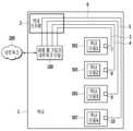
도 1을 참조하면, 댁내(1)에는 댁내 단자함(2)이 구비된다. 댁내 단자함(2)의 벽면에 매립되어 형성된 부분인 함체 내 공간은 댁내 배선(3, 4, 5, 6)의 결집점(hub)이 된다. 이러한 댁내 단자함(2)은 댁내망의 최초 인입점의 역할을 한다.Referring to FIG. 1, the home (1) is provided with an in-house terminal box (2). The space within the box, which is a part formed by being embedded in the wall of the home terminal box (2), becomes a hub for the home wiring (3, 4, 5, and 6). This in-house terminal box (2) serves as the first entry point into the in-house network.
댁내 단자함(2)으로부터 랜(LAN, Local Area Network) UTP(unshielded twisted pair cable) 성형 배선 또는 전화선 성형 배선(이하, '댁내 배선'으로 통칭함)(3, 4, 5, 6) 이 갈려져 나가서 방, 거실, 주방 등으로 연결된다. 이때, 방, 거실, 주방 등에는 데이터 통신을 위한 RJ45 댁내 접속 단자 또는 RJ11 댁내 접속 단자(7, 8, 9, 10)가 설치된다. 여기서, RJ45는 8핀으로 일반적으로 사용하는 랜선(UTP 케이블)용이고, RJ11은 대표적으로 전화선용으로서, 4핀(4P4C), 4핀(6P4C), 6핀(6P6C)의 3종류가 있다.LAN (Local Area Network) UTP (unshielded twisted pair cable) star wiring or telephone line star wiring (hereinafter collectively referred to as 'home wiring') (3, 4, 5, 6) is separated from the terminal box (2) in the home. It goes out and connects to the bedroom, living room, kitchen, etc. At this time, RJ45 in-house connection terminals or RJ11 in-house connection terminals (7, 8, 9, 10) for data communication are installed in the room, living room, kitchen, etc. Here, RJ45 is an 8-pin commonly used LAN cable (UTP cable), and RJ11 is typically used for telephone lines, and there are three types: 4-pin (4P4C), 4-pin (6P4C), and 6-pin (6P6C).
댁내 배선(3, 4, 5, 6)은 벽 속을 따라 집안을 한 바퀴 돌아서 통상 주방이나 현관에 설치된 댁내 단자함(2)으로 모인다.The house wiring (3, 4, 5, 6) goes around the house along the inside of the wall and gathers in the house terminal box (2), which is usually installed in the kitchen or entrance.
본 발명의 실시예에 따른 범용 홈 가입자 네트워크 단말(Universal Home User Network Terminal, U-HUNT)(100)은 인터넷(200)과 광케이블 또는 랜선/전화선과 연결된다. 여기서, 인터넷(200)은 댁내광가입자망(FTTH)이거나, xDSL, 이더넷, 기가 이더넷과 같은 유선통신망을 포함할 수 있다.The Universal Home User Network Terminal (U-HUNT) 100 according to an embodiment of the present invention is connected to the Internet 200 and an optical cable or LAN/telephone line. Here, the Internet 200 may be a FTTH (FTTH) network or may include a wired communication network such as xDSL, Ethernet, or Giga Ethernet.
이처럼, 범용 홈 가입자 네트워크 단말(100)을 개통 후 인터넷망(200)에 연결시키고, 댁내 배선(3, 4, 5, 6)과 연결시킨다. 그리고 각각의 댁내 단말(301, 303, 305, 307)은 각각의 댁내 접속 단자(7, 8, 9, 10)와 접속시키면, 고객이 직접 댁내 어느 방에서나 별도의 선로 구성없이 네트워크에 접속할 수 있다.In this way, after opening the universal home
도 2는 본 발명의 실시예에 따른 홈 가입자 네트워크 단말의 세부적인 구성을 나타낸 블록도이다.Figure 2 is a block diagram showing the detailed configuration of a home subscriber network terminal according to an embodiment of the present invention.
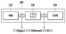
도 2를 참조하면, 홈 가입자 네트워크 단말(100)은 네트워크 인터페이스(Network Network Interface, 이하 'NNI'로 통칭함)(110), 스위치 또는 브릿지(130) 및 범용 가입자 인터페이스(Universal User Network Interface, 이하 'UUNI'로 통칭함)(150)를 포함한다.Referring to FIG. 2, the home
이때, NNI(110)와 스위치/브릿지(130), 스위치/브릿지(150)와 UUNI(150)는 기가(Giga)급 이더넷(Ethernet) 인터페이스로 연결된다.At this time, the NNI (110), the switch/
NNI(110)는 통신 국사와 연결된 광 케이블(미도시), 랜 케이블(미도시), 전화선(미도시) 중 하나와 직접 접속된다.The NNI 110 is directly connected to one of an optical cable (not shown), a LAN cable (not shown), or a telephone line (not shown) connected to a communication office.
NNI(110)는 PON(passive optical network)의 광 케이블 또는 이더넷(Ethernet) 등의 동선과 접속되는 모듈로서, 선택적으로 탈착이 가능한 형태로 구현된다.The NNI 110 is a module connected to an optical cable of a passive optical network (PON) or a copper wire such as Ethernet, and is implemented in a selectively detachable form.
NNI(110)는는 초고속 인터넷 정합 기능으로써, 인터넷 접속이 제공 기술방식에 따라 상이할 수 있으므로 FTTH 또는 동선 기반 전송 기술(Ethernet, xDSL, G.hn, G.fast 등)를 지원하는 탈착형 모듈 커넥터로 구현될 수 있다. 또한, UUNI를 지원하는 탈착형 모듈 커넥터로 구현될 수도 있다.NNI (110) is a high-speed Internet matching function. Since Internet access may vary depending on the technology provided, it is a detachable module connector that supports FTTH or copper wire-based transmission technology (Ethernet, xDSL, G.hn, G.fast, etc.) It can be implemented as: Additionally, it can be implemented as a detachable module connector that supports UUNI.
스위치(Switch)/브릿지(Bridge)(130)는 댁내 배선 형태에 따라 스위치 또는 브릿지 중 하나로 구현된다.Switch/Bridge 130 is implemented as either a switch or a bridge depending on the wiring type in the home.
댁내 접속 단자가 1개일 경우, 1 대 1 방식이므로, 브릿지로 구현된다. 이때, 브릿지는 기가(Giga)급 이더넷(Ethernet) 인터페이스 버스간 정합 기능을 수행한다.If there is only one connection terminal in the house, it is implemented as a bridge because it is a 1 to 1 connection. At this time, the bridge performs a matching function between Giga-class Ethernet interface buses.
댁내 접속 단자가 n개일 경우, 1 대 n 방식이므로, 스위치로 구현된다. 스위치는 NNI 포트(110)와 UUNI 포트(150)간 라우팅 기능을 수행한다.If there are n connection terminals in the house, it is implemented as a switch because it is a 1 to n method. The switch performs a routing function between the NNI port (110) and the UUNI port (150).
UUNI(150)는 RJ45 또는 RJ11 등 댁내 배선 커넥터로 구현된다. 그리고 댁내 배선을 동일 포트로 연결하여 댁내 단말과 접속할 수 있는 기능을 제공한다. 여기서, 댁내 단말은 공유기, 셋탑박스, 노트북 등이 될 수 있다.UUNI (150) is implemented with an in-house wiring connector such as RJ45 or RJ11. It also provides the ability to connect to a terminal within the home by connecting the wiring within the home to the same port. Here, the in-house terminal may be a router, set-top box, laptop, etc.
도 3은 도 2의 UUNI의 세부적인 구성을 나타낸 블록도이다.FIG. 3 is a block diagram showing the detailed configuration of UUNI of FIG. 2.
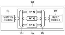
도 3을 참조하면, 범용 가입자 인터페이스(UUNI)(150)는 다양한 댁내 선로 종류(전화선, LAN선 등)에 동일 포트를 통한 접속 기능을 제공한다.Referring to FIG. 3, the universal subscriber interface (UUNI) 150 provides a connection function to various in-house line types (telephone lines, LAN lines, etc.) through the same port.
세부적으로, 탈착형 모듈 인터페이스(151), 제1 기능부(153), 복수개의 파이(PHY #1, …, PHY #n) 모듈(155), 제2 기능부(157) 및 아날로그 인터페이스(159)를 포함한다.In detail, a
탈착형 모듈 인터페이스(151)는 WAN(Wide Area Network) 상대국 전송 방식(PON, Ethernet, G.hn 등)의 신호를 종단, 이더넷(Ethernet) 인터페이스로 전달 기능을 수행한다. SFP(Small Form Factor Pluggable) 표준 인터페이스(MSA 등)를 지원할 수 있다.The
제1 기능부(153)는 WAN 측 적용 기술방식에 따라 복수개의 파이(PHY #1, …, PHY #n) 모듈(155) 중에서 하나의 전송 파이(PHY) 모듈 선택하여 탈착형 모듈 인터페이스(151)와 회선 구성(회로로 연결되는 구성)하는 기능을 수행한다.The first
복수개의 파이(PHY #1, …, PHY #n) 모듈(155)은 물리 계층에 대한 처리를 수행하는데, 댁내 단말(공유기, 셋탑박스, 노트북 등) 전송 기술 방식의 PHY 기능을 수행하며, 서로 다른 전송 기술 방식 별로 복수개로 구현된다. 도면에는 별개의 모듈로 독립적인 기능부로 도시하였지만, 물리적인 구성은 하나의 파이 모듈로 구현되나, 내부에 서로 다른 전송 기술 방식을 선택적으로 구현 가능한 통합 기능부의 형태로 구성될 수도 있다.A plurality of Pi (
제2 기능부(157)는 댁내 배선의 선로 종류에 따라 선택된 파이(PHY #1, …, PHY #n) 모듈(155)와 아날로그 인터페이스(159)간 회선 구성하는 기능을 수행한다.The second
아날로그 인터페이스(159)는 전화선 또는 랜선에 임피던스 정합 및 아날로그 신호 왜곡 또는 감쇄 없이 전달하는 수동 회로로 구성된다. 아날로그 인터페이스(159)는 일측이 댁내 접속 단자(7, 8, 9, 10)에 연결된 댁내 배선(1, 2, 3, 4,)과 연결된다.The
이때, 제1 기능부(153) 및 제2 기능부(157)는 초기 회선을 구성하기 위해 PHY #1 부터 순차적으로 자동 협상(Auto Negotiation)을 시작하여 WAN 상대국의 기술 방식과 댁내 단말의 전송 방식이 매칭되지 않을 경우, 이를 감지하여 다음 PHY로 자동 협상을 시도한다. 이러한 방식으로 n개의 PHY에 대해 자동 협상이 완료 될 때까지 진행한다. 이때, 아날로그 인터페이스(159)에 댁내 단말이 연결된 상태에서 제1 기능부(153)와 제2 기능부(157)는 PHY #1와 연결된 상태에서 해당 전송 방식의 신호(펄스 형태)를 아날로그 인터페이스(159)를 통해 출력한다. 그리고 아날로그 인터페이스(159)를 통해 댁내 단말로부터 수신된 신호의 파형이 댁내 단말로 전송한 신호의 파형과 일치하지 않으면, 다음 PHY #2로 협상 절차가 이루어진다. 이런 방식으로 WAN 상대국의 기술 방식과 댁내 단말의 전송 방식이 매칭될 때까지 협상 절차가 반복된다. 여기서, 댁내 단말로 파형 신호를 전송하면, 자신의 전송 방식에 맞는 파형 신호를 전송하도록 하는 것은 모든 댁내 단말에 포함되어 있는 기능이다.At this time, the first
도 4 ~ 도 8은 본 발명의 실시예에 따른 범용 홈 가입자 네트워크 단말의 구현 예시도이다.Figures 4 to 8 are diagrams illustrating the implementation of a general-purpose home subscriber network terminal according to an embodiment of the present invention.
도 4는 본 발명의 한 실시예에 따른 범용 홈 가입자 네트워크 단말의 구현 예시도로서, 하나의 댁내 배선이 랜선으로 되어 있는 경우의 실시예이다.Figure 4 is an exemplary implementation diagram of a general-purpose home subscriber network terminal according to an embodiment of the present invention, which is an embodiment in the case where one in-house wiring is a LAN cable.
도 4를 참조하면, 댁내 배선은 랜선으로 되어 있고, 댁내 접속 단자(7, 8, 9, 10 중 택일)와 연결된 댁내 배선(1, 2, 3, 4 중 택일)과 UUNI(150)가 연결된다. 그리고 댁내 접속 단자(7, 8, 9, 10 중 택일)는 댁내 단말(300)과 랜 케이블으로 연결된다.Referring to Figure 4, the in-house wiring is a LAN cable, and the in-house wiring (select one of 1, 2, 3, or 4) connected to the in-house connection terminal (select one of 7, 8, 9, or 10) and UUNI (150) are connected. do. And the in-house connection terminal (select one of 7, 8, 9, and 10) is connected to the in-
이때, 범용 홈 가입자 네트워크 단말(100)은 브릿지(130)가 NNI(110) 및 UUNI(150)와 각각 연결되어 있다.At this time, the
이처럼, 브릿지(130)는 UUNI(150)가 한 개일 경우, NNI(110)와 UUNI(150)간 라우팅 기능을 수행한다.As such, the
도 5는 본 발명의 다른 실시예에 따른 범용 홈 가입자 네트워크 단말의 구현 예시도로서, 복수개의 댁내 배선이 랜선으로 되어 있는 경우의 실시예이다.Figure 5 is an exemplary implementation diagram of a general-purpose home subscriber network terminal according to another embodiment of the present invention, which is an embodiment in which a plurality of in-house wiring is made of LAN cables.
도 5를 참조하면, 도 4와 구성이 동일하나, 다만, 댁내 배선이 복수개이므로, 댁내 배선 만큼 UUNI가 복수개 구비되고, 복수개의 UUNI(150)는 스위치(130)를 통해 NNI(110)와 연결된다.Referring to FIG. 5, the configuration is the same as that of FIG. 4, but since there are multiple in-house wiring, a plurality of UUNIs are provided as many as the in-house wiring, and the plurality of
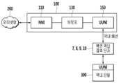
도 6은 본 발명의 또 다른 실시예에 따른 범용 홈 가입자 네트워크 단말의 구현 예시도로서, 하나의 댁내 배선이 전화선으로 되어 있는 경우의 실시예이다.Figure 6 is an exemplary implementation diagram of a general-purpose home subscriber network terminal according to another embodiment of the present invention, which is an embodiment in the case where one in-house wiring is a telephone line.
도 6을 참조하면, 댁내 배선은 전화선으로 되어 있고, 댁내 접속 단자(7, 8, 9, 10 중 택일)와 연결된 댁내 배선(1, 2, 3, 4 중 택일)과 브릿지(130)가 연결된다.Referring to FIG. 6, the in-house wiring is a telephone line, and the in-house wiring (select among 1, 2, 3, and 4) connected to the in-house connection terminal (select among 7, 8, 9, and 10) is connected to the
이때, 범용 홈 가입자 네트워크 단말(100)은 브릿지(130)가 NNI(110) 및 UUNI(150)와 각각 연결되어 있다. 그리고 UUNI(150)는 댁내 배선을 통해 벽면 댁내 접속 단자(7, 8, 9, 10)와 연결된다.At this time, the
이때, 댁내 단말(300)은 사용자가 별도로 구매하여 별도로 구비한 UUNI를 통해 댁내 접속 단자(7, 8, 9, 10)와 연결된다. 예를들면, UUNI(150)의 탈착형 모듈 인터페이스(151)는 RJ11 커넥터가 마련된 케이블(미도시)을 이용하여 댁내 접속 단자(7, 8, 9, 10)와 연결된다. 그리고 댁내 단말(300)과 UUNI(150)의 아날로그 인터페이스(159)는 케이블(RJ11 커넥터가 마련된 케이블 또는 랜 케이블)을 이용하여 서로 연결된다.At this time, the in-
가입자가 자신의 집에 전화선만 배선되어 있는 경우, 별도로 구비된 UUNI(150)만 구입하여 댁내 접속 단자(7, 8, 9, 10 중 택일)에 UUNI(150)를 연결시킨다.If the subscriber only has a telephone line wired in his or her home, purchase only the separately provided UUNI (150) and connect the UUNI (150) to the in-house connection terminal (select one of 7, 8, 9, or 10).
도 7은 본 발명의 또 다른 실시예에 따른 범용 홈 가입자 네트워크 단말의 구현 예시도로서, 복수개의 댁내 배선이 전화선으로 되어 있는 경우의 실시예이다Figure 7 is an exemplary implementation diagram of a general-purpose home subscriber network terminal according to another embodiment of the present invention, which is an embodiment in the case where a plurality of in-house wiring is made of telephone lines.
도 7을 참조하면, 도 6과 구성이 동일하나, 다만, 댁내 배선이 복수개이므로, 댁내 배선 만큼 UUNI가 복수개 구비되고, 스위치(130)를 포함한다.Referring to FIG. 7, the configuration is the same as that of FIG. 6, but since there are multiple wirings in the home, a plurality of UUNIs are provided as many as the wiring in the home and include a
도 8은 본 발명의 또 다른 실시예에 따른 범용 홈 가입자 네트워크 단말의 구현 예시도로서, 복수개의 댁내 배선이 랜선과 전화선이 혼합된 경우의 실시예를 나타낸다.Figure 8 is an exemplary implementation of a general-purpose home subscriber network terminal according to another embodiment of the present invention, showing an embodiment in which a plurality of in-house wiring is a mixture of LAN cables and telephone lines.
도 8을 참조하면, 도 4와 도 6이 결합된 실시예를 도시하였지만, 도 4, 5, 6, 7의 실시예 중에서 선택된 복수의 실시예가 결합된 형태로 구현될 수 있다.Referring to FIG. 8, although an embodiment in which FIGS. 4 and 6 are combined is shown, a plurality of embodiments selected from the embodiments of FIGS. 4, 5, 6, and 7 may be implemented in a combined form.
이상에서 설명한 본 발명의 실시예는 장치 및 방법을 통해서만 구현이 되는 것은 아니며, 본 발명의 실시예의 구성에 대응하는 기능을 실현하는 프로그램 또는 그 프로그램이 기록된 기록 매체를 통해 구현될 수도 있다.The embodiments of the present invention described above are not only implemented through devices and methods, but can also be implemented through programs that implement functions corresponding to the configurations of the embodiments of the present invention or recording media on which the programs are recorded.
이상에서 본 발명의 실시예에 대하여 상세하게 설명하였지만 본 발명의 권리범위는 이에 한정되는 것은 아니고 다음의 청구범위에서 정의하고 있는 본 발명의 기본 개념을 이용한 당업자의 여러 변형 및 개량 형태 또한 본 발명의 권리범위에 속하는 것이다.Although the embodiments of the present invention have been described in detail above, the scope of the present invention is not limited thereto, and various modifications and improvements made by those skilled in the art using the basic concept of the present invention defined in the following claims are also possible. It falls within the scope of rights.
Claims (4)
Translated fromKorean댁내 단말과 접속되어 상기 댁내 단말을 상기 WAN에 연결시키는 범용 가입자 인터페이스(Universal User Network Interface, UUNI), 그리고
상기 네트워크 인터페이스(NNI)와 상기 범용 가입자 인터페이스(UUNI)를 연결시키는 스위치 또는 브릿지를 포함하고,
상기 범용 가입자 인터페이스(UUNI)는,
상기 스위치 또는 상기 브릿지와 연결되어, 상기 WAN으로부터 수신되는 신호를 전달하는 모듈 인터페이스,
댁내 배선을 통해 댁내 단말과 연결되어, 상기 댁내 단말과 신호를 송수신하는 아날로그 인터페이스,
서로 다른 복수개의 WAN 전송 기술 방식에 따른 각각의 물리 계층에 대한 처리를 수행하는 복수개의 물리 계층(PHY) 모듈,
상기 모듈 인터페이스와 물리 계층(PHY) 모듈 간 회선을 구성하는 제1 기능부, 그리고
물리 계층(PHY) 모듈과 상기 아날로그 인터페이스 간 회선을 구성하는 제2 기능부를 포함하고,
상기 제1 기능부와 상기 제2 기능부는,
상기 복수개의 물리 계층(PHY) 모듈을 순차적으로 하나씩 선택적으로 연결한 상태에서 상기 네트워크 인터페이스(NNI)의 WAN 전송 방식에 따른 신호를 상기 댁내 단말에게 출력하여 상기 댁내 단말로부터 신호를 수신하고, 출력한 신호의 파형과 수신한 신호의 파형을 비교하여 파형들이 일치하는 물리 계층(PHY) 모듈을 선택하며,
상기 제1 기능부는,
선택한 물리 계층(PHY) 모듈과 상기 모듈 인터페이스 간에 회선을 구성하고,
상기 제2 기능부는,
상기 선택한 물리 계층(PHY) 모듈과 상기 아날로그 인터페이스 간 회선을 구성하는, 범용 홈 가입자 네트워크 단말.A network interface (NNI) that is connected to a wide area network (WAN) and transmits and receives signals to and from the WAN,
A universal subscriber interface (Universal User Network Interface, UUNI) that is connected to an in-house terminal and connects the in-house terminal to the WAN, and
Comprising a switch or bridge connecting the network interface (NNI) and the universal subscriber interface (UUNI),
The universal subscriber interface (UUNI) is,
A module interface connected to the switch or bridge and transmitting signals received from the WAN,
An analog interface that is connected to an in-house terminal through in-house wiring and transmits and receives signals to and from the in-house terminal,
A plurality of physical layer (PHY) modules that perform processing for each physical layer according to a plurality of different WAN transmission technology methods,
A first functional unit configuring a line between the module interface and a physical layer (PHY) module, and
It includes a second functional unit that configures a line between a physical layer (PHY) module and the analog interface,
The first functional unit and the second functional unit,
With the plurality of physical layer (PHY) modules sequentially and selectively connected one by one, a signal according to the WAN transmission method of the network interface (NNI) is output to the in-house terminal, and a signal is received and output from the in-house terminal. Compares the waveform of the signal with the waveform of the received signal and selects the physical layer (PHY) module whose waveforms match.
The first functional unit,
Configure a line between the selected physical layer (PHY) module and the module interface,
The second functional unit,
A universal home subscriber network terminal that configures a circuit between the selected physical layer (PHY) module and the analog interface.
상기 모듈 인터페이스는, 탈착형 모듈 인터페이스이고,
상기 WAN 전송 방식은,
PON(passive optical network), FTTH(Fiber To The Home), 이더넷(Ethernet), xDSL(xDigital Subscriber Line), G.hn, G.fast 중 적어도 하나를 포함하고,
상기 복수개의 물리 계층(PHY) 모듈은,
상기 WAN 전송 방식에 따른 물리 계층에 대한 처리를 수행하는, 범용 홈 가입자 네트워크 단말.According to paragraph 1,
The module interface is a detachable module interface,
The WAN transmission method is,
Includes at least one of PON (passive optical network), FTTH (Fiber To The Home), Ethernet, xDSL (xDigital Subscriber Line), G.hn, and G.fast,
The plurality of physical layer (PHY) modules are,
A general-purpose home subscriber network terminal that performs physical layer processing according to the WAN transmission method.
상기 아날로그 인터페이스는,
임피던스 정합, 그리고 아날로그 신호 왜곡 또는 감쇄를 수반하지 않는 수동 회로로 구성되고, 일측이 댁내 접속 단자에 연결된 댁내 배선의 타측에 접속되며,
상기 댁내 접속 단자에는,
상기 댁내 단말이 접속되는, 범용 홈 가입자 네트워크 단말.According to paragraph 2,
The analog interface is,
It consists of impedance matching and a passive circuit that does not involve distortion or attenuation of the analog signal, and one side is connected to the other side of the in-house wiring connected to the in-house connection terminal,
To the above-mentioned in-house connection terminal,
A universal home subscriber network terminal to which the in-house terminal is connected.
독립된 모듈형 범용 가입자 인터페이스(UUNI)를 더 포함하고,
상기 독립된 모듈형 범용 가입자 인터페이스(UUNI)는,
상기 복수개의 물리 계층(PHY) 모듈,
상기 제1 기능부,
상기 제2 기능부,
댁내 배선을 통해 벽면 댁내 접속 단자에 접속되는 탈착형 모듈 인터페이스, 그리고
댁내 단말과 전화선을 통해 연결되는 아날로그 인터페이스를 포함하고,
상기 탈착형 모듈 인터페이스에 연결된 벽면 댁내 접속 단자는,
상기 네트워크 인터페이스(NNI)와 연결된 상기 범용 가입자 인터페이스(UUNI)와 댁내 배선을 통해 연결되며,
상기 네트워크 인터페이스(NNI)의 WAN 전송 방식에 따른 신호는,
상기 범용 가입자 인터페이스(UUNI)로부터 상기 벽면 댁내 접속 단자를 통해 상기 독립된 모듈형 범용 가입자 인터페이스(UUNI)로 전달되는, 범용 홈 가입자 네트워크 단말.
According to paragraph 3,
Further comprising an independent modular universal subscriber interface (UUNI),
The independent modular universal subscriber interface (UUNI),
The plurality of physical layer (PHY) modules,
The first functional unit,
the second functional unit,
A detachable module interface that is connected to the in-house connection terminal on the wall through in-house wiring, and
It includes an analog interface connected to the in-house terminal via a telephone line,
The wall in-house connection terminal connected to the detachable module interface is,
It is connected to the universal subscriber interface (UUNI) connected to the network interface (NNI) through in-house wiring,
The signal according to the WAN transmission method of the network interface (NNI) is,
A universal home subscriber network terminal transmitted from the universal subscriber interface (UUNI) to the independent modular universal subscriber interface (UUNI) through the wall in-house connection terminal.
Priority Applications (1)
| Application Number | Priority Date | Filing Date | Title |
|---|---|---|---|
| KR1020150187220AKR102638732B1 (en) | 2015-12-28 | 2015-12-28 | Universal home subscriber network terminal |
Applications Claiming Priority (1)
| Application Number | Priority Date | Filing Date | Title |
|---|---|---|---|
| KR1020150187220AKR102638732B1 (en) | 2015-12-28 | 2015-12-28 | Universal home subscriber network terminal |
Publications (2)
| Publication Number | Publication Date |
|---|---|
| KR20170077385A KR20170077385A (en) | 2017-07-06 |
| KR102638732B1true KR102638732B1 (en) | 2024-02-19 |
Family
ID=59353966
Family Applications (1)
| Application Number | Title | Priority Date | Filing Date |
|---|---|---|---|
| KR1020150187220AActiveKR102638732B1 (en) | 2015-12-28 | 2015-12-28 | Universal home subscriber network terminal |
Country Status (1)
| Country | Link |
|---|---|
| KR (1) | KR102638732B1 (en) |
Citations (1)
| Publication number | Priority date | Publication date | Assignee | Title |
|---|---|---|---|---|
| JP2004165773A (en)* | 2002-11-11 | 2004-06-10 | Matsushita Electric Ind Co Ltd | Network connection device |
Family Cites Families (3)
| Publication number | Priority date | Publication date | Assignee | Title |
|---|---|---|---|---|
| KR100719443B1 (en)* | 2005-11-11 | 2007-05-17 | (주)네오정보시스템 | Wireless LAN Hybrid Generation Communication Distribution Device |
| KR20080057614A (en)* | 2006-12-20 | 2008-06-25 | 대은전자 주식회사 | Integrated telephone and data network with UTIP cable |
| US20130201519A1 (en)* | 2012-02-03 | 2013-08-08 | Apple Inc. | Bridging Non-Network Interfaces and Network Interfaces |
- 2015
- 2015-12-28KRKR1020150187220Apatent/KR102638732B1/enactiveActive
Patent Citations (1)
| Publication number | Priority date | Publication date | Assignee | Title |
|---|---|---|---|---|
| JP2004165773A (en)* | 2002-11-11 | 2004-06-10 | Matsushita Electric Ind Co Ltd | Network connection device |
Also Published As
| Publication number | Publication date |
|---|---|
| KR20170077385A (en) | 2017-07-06 |
Similar Documents
| Publication | Publication Date | Title |
|---|---|---|
| US8279805B2 (en) | Residential gateway | |
| US7990908B2 (en) | Addressable outlet, and a network using the same | |
| US9965349B2 (en) | Identifying network performance alert conditions | |
| US9742704B2 (en) | Physical layer management at a wall plate device | |
| US8687506B2 (en) | Identifying network performance alert conditions | |
| US8887220B2 (en) | Network interface devices | |
| CN105847051A (en) | System for communication, connector assembly, and equipment for communication | |
| US9865976B2 (en) | High-density data communications cable | |
| US20040180573A1 (en) | Connection-safe network hub | |
| US11081847B2 (en) | High-density split cable | |
| US20200351117A1 (en) | Adaptive Network Access System for Existing Infrastructure | |
| KR102638732B1 (en) | Universal home subscriber network terminal | |
| US10931474B2 (en) | Cascaded distribution point unit architecture for an adaptive network access system | |
| KR100756244B1 (en) | Power over Ethernet based LAN repeater and Power over Ethernet hybrid repeater | |
| US10177516B2 (en) | High-density bridge adapter | |
| KR102464404B1 (en) | System for integrating wiring management including network separation function | |
| US10637993B1 (en) | High-bandwidth home network over phone line | |
| US20150381236A1 (en) | Method and apparatus in a communications network | |
| US20030147523A1 (en) | HPNA network bridge | |
| US8355498B2 (en) | Communication line interface | |
| NL2008238C2 (en) | Scalable media converter for use in a multi-dwelling unit. | |
| JP2000050474A (en) | Information outlets and wiring systems | |
| KR20090022300A (en) | Apparatus and method for transmitting Ethernet signals via telephone cable | |
| JP2000032505A (en) | Information outlet installation method and wiring system | |
| HK1177994A (en) | Outlet with analog signal adapter |
Legal Events
| Date | Code | Title | Description |
|---|---|---|---|
| PA0109 | Patent application | Patent event code:PA01091R01D Comment text:Patent Application Patent event date:20151228 | |
| PG1501 | Laying open of application | ||
| A201 | Request for examination | ||
| PA0201 | Request for examination | Patent event code:PA02012R01D Patent event date:20201228 Comment text:Request for Examination of Application Patent event code:PA02011R01I Patent event date:20151228 Comment text:Patent Application | |
| E902 | Notification of reason for refusal | ||
| PE0902 | Notice of grounds for rejection | Comment text:Notification of reason for refusal Patent event date:20230810 Patent event code:PE09021S01D | |
| E701 | Decision to grant or registration of patent right | ||
| PE0701 | Decision of registration | Patent event code:PE07011S01D Comment text:Decision to Grant Registration Patent event date:20240112 | |
| GRNT | Written decision to grant | ||
| PR0701 | Registration of establishment | Comment text:Registration of Establishment Patent event date:20240215 Patent event code:PR07011E01D | |
| PR1002 | Payment of registration fee | Payment date:20240215 End annual number:3 Start annual number:1 | |
| PG1601 | Publication of registration |