KR102638297B1 - Manufacturing method and apparatus for a display device - Google Patents
Manufacturing method and apparatus for a display deviceDownload PDFInfo
- Publication number
- KR102638297B1 KR102638297B1KR1020160122380AKR20160122380AKR102638297B1KR 102638297 B1KR102638297 B1KR 102638297B1KR 1020160122380 AKR1020160122380 AKR 1020160122380AKR 20160122380 AKR20160122380 AKR 20160122380AKR 102638297 B1KR102638297 B1KR 102638297B1
- Authority
- KR
- South Korea
- Prior art keywords
- jig
- cover window
- panel member
- display device
- seesaw
- Prior art date
- Legal status (The legal status is an assumption and is not a legal conclusion. Google has not performed a legal analysis and makes no representation as to the accuracy of the status listed.)
- Active
Links
Images


Classifications
- B—PERFORMING OPERATIONS; TRANSPORTING
- B32—LAYERED PRODUCTS
- B32B—LAYERED PRODUCTS, i.e. PRODUCTS BUILT-UP OF STRATA OF FLAT OR NON-FLAT, e.g. CELLULAR OR HONEYCOMB, FORM
- B32B38/00—Ancillary operations in connection with laminating processes
- B32B38/18—Handling of layers or the laminate
- B32B38/1866—Handling of layers or the laminate conforming the layers or laminate to a convex or concave profile
- G—PHYSICS
- G06—COMPUTING OR CALCULATING; COUNTING
- G06F—ELECTRIC DIGITAL DATA PROCESSING
- G06F3/00—Input arrangements for transferring data to be processed into a form capable of being handled by the computer; Output arrangements for transferring data from processing unit to output unit, e.g. interface arrangements
- G06F3/01—Input arrangements or combined input and output arrangements for interaction between user and computer
- G06F3/03—Arrangements for converting the position or the displacement of a member into a coded form
- G06F3/041—Digitisers, e.g. for touch screens or touch pads, characterised by the transducing means
- G06F3/0412—Digitisers structurally integrated in a display
- B—PERFORMING OPERATIONS; TRANSPORTING
- B25—HAND TOOLS; PORTABLE POWER-DRIVEN TOOLS; MANIPULATORS
- B25B—TOOLS OR BENCH DEVICES NOT OTHERWISE PROVIDED FOR, FOR FASTENING, CONNECTING, DISENGAGING OR HOLDING
- B25B11/00—Work holders not covered by any preceding group in the subclass, e.g. magnetic work holders, vacuum work holders
- B—PERFORMING OPERATIONS; TRANSPORTING
- B32—LAYERED PRODUCTS
- B32B—LAYERED PRODUCTS, i.e. PRODUCTS BUILT-UP OF STRATA OF FLAT OR NON-FLAT, e.g. CELLULAR OR HONEYCOMB, FORM
- B32B3/00—Layered products comprising a layer with external or internal discontinuities or unevennesses, or a layer of non-planar shape; Layered products comprising a layer having particular features of form
- B32B3/02—Layered products comprising a layer with external or internal discontinuities or unevennesses, or a layer of non-planar shape; Layered products comprising a layer having particular features of form characterised by features of form at particular places, e.g. in edge regions
- B32B3/04—Layered products comprising a layer with external or internal discontinuities or unevennesses, or a layer of non-planar shape; Layered products comprising a layer having particular features of form characterised by features of form at particular places, e.g. in edge regions characterised by at least one layer folded at the edge, e.g. over another layer ; characterised by at least one layer enveloping or enclosing a material
- B—PERFORMING OPERATIONS; TRANSPORTING
- B32—LAYERED PRODUCTS
- B32B—LAYERED PRODUCTS, i.e. PRODUCTS BUILT-UP OF STRATA OF FLAT OR NON-FLAT, e.g. CELLULAR OR HONEYCOMB, FORM
- B32B3/00—Layered products comprising a layer with external or internal discontinuities or unevennesses, or a layer of non-planar shape; Layered products comprising a layer having particular features of form
- B32B3/26—Layered products comprising a layer with external or internal discontinuities or unevennesses, or a layer of non-planar shape; Layered products comprising a layer having particular features of form characterised by a particular shape of the outline of the cross-section of a continuous layer; characterised by a layer with cavities or internal voids ; characterised by an apertured layer
- B32B3/28—Layered products comprising a layer with external or internal discontinuities or unevennesses, or a layer of non-planar shape; Layered products comprising a layer having particular features of form characterised by a particular shape of the outline of the cross-section of a continuous layer; characterised by a layer with cavities or internal voids ; characterised by an apertured layer characterised by a layer comprising a deformed thin sheet, i.e. the layer having its entire thickness deformed out of the plane, e.g. corrugated, crumpled
- B—PERFORMING OPERATIONS; TRANSPORTING
- B32—LAYERED PRODUCTS
- B32B—LAYERED PRODUCTS, i.e. PRODUCTS BUILT-UP OF STRATA OF FLAT OR NON-FLAT, e.g. CELLULAR OR HONEYCOMB, FORM
- B32B37/00—Methods or apparatus for laminating, e.g. by curing or by ultrasonic bonding
- B32B37/0007—Methods or apparatus for laminating, e.g. by curing or by ultrasonic bonding involving treatment or provisions in order to avoid deformation or air inclusion, e.g. to improve surface quality
- B—PERFORMING OPERATIONS; TRANSPORTING
- B32—LAYERED PRODUCTS
- B32B—LAYERED PRODUCTS, i.e. PRODUCTS BUILT-UP OF STRATA OF FLAT OR NON-FLAT, e.g. CELLULAR OR HONEYCOMB, FORM
- B32B37/00—Methods or apparatus for laminating, e.g. by curing or by ultrasonic bonding
- B32B37/10—Methods or apparatus for laminating, e.g. by curing or by ultrasonic bonding characterised by the pressing technique, e.g. using action of vacuum or fluid pressure
- B32B37/1009—Methods or apparatus for laminating, e.g. by curing or by ultrasonic bonding characterised by the pressing technique, e.g. using action of vacuum or fluid pressure using vacuum and fluid pressure
- B—PERFORMING OPERATIONS; TRANSPORTING
- B32—LAYERED PRODUCTS
- B32B—LAYERED PRODUCTS, i.e. PRODUCTS BUILT-UP OF STRATA OF FLAT OR NON-FLAT, e.g. CELLULAR OR HONEYCOMB, FORM
- B32B37/00—Methods or apparatus for laminating, e.g. by curing or by ultrasonic bonding
- B32B37/10—Methods or apparatus for laminating, e.g. by curing or by ultrasonic bonding characterised by the pressing technique, e.g. using action of vacuum or fluid pressure
- B32B37/1018—Methods or apparatus for laminating, e.g. by curing or by ultrasonic bonding characterised by the pressing technique, e.g. using action of vacuum or fluid pressure using only vacuum
- B—PERFORMING OPERATIONS; TRANSPORTING
- B32—LAYERED PRODUCTS
- B32B—LAYERED PRODUCTS, i.e. PRODUCTS BUILT-UP OF STRATA OF FLAT OR NON-FLAT, e.g. CELLULAR OR HONEYCOMB, FORM
- B32B7/00—Layered products characterised by the relation between layers; Layered products characterised by the relative orientation of features between layers, or by the relative values of a measurable parameter between layers, i.e. products comprising layers having different physical, chemical or physicochemical properties; Layered products characterised by the interconnection of layers
- B32B7/04—Interconnection of layers
- B32B7/12—Interconnection of layers using interposed adhesives or interposed materials with bonding properties
- G—PHYSICS
- G02—OPTICS
- G02F—OPTICAL DEVICES OR ARRANGEMENTS FOR THE CONTROL OF LIGHT BY MODIFICATION OF THE OPTICAL PROPERTIES OF THE MEDIA OF THE ELEMENTS INVOLVED THEREIN; NON-LINEAR OPTICS; FREQUENCY-CHANGING OF LIGHT; OPTICAL LOGIC ELEMENTS; OPTICAL ANALOGUE/DIGITAL CONVERTERS
- G02F1/00—Devices or arrangements for the control of the intensity, colour, phase, polarisation or direction of light arriving from an independent light source, e.g. switching, gating or modulating; Non-linear optics
- G02F1/01—Devices or arrangements for the control of the intensity, colour, phase, polarisation or direction of light arriving from an independent light source, e.g. switching, gating or modulating; Non-linear optics for the control of the intensity, phase, polarisation or colour
- G02F1/13—Devices or arrangements for the control of the intensity, colour, phase, polarisation or direction of light arriving from an independent light source, e.g. switching, gating or modulating; Non-linear optics for the control of the intensity, phase, polarisation or colour based on liquid crystals, e.g. single liquid crystal display cells
- G02F1/133—Constructional arrangements; Operation of liquid crystal cells; Circuit arrangements
- G02F1/1333—Constructional arrangements; Manufacturing methods
- G—PHYSICS
- G06—COMPUTING OR CALCULATING; COUNTING
- G06F—ELECTRIC DIGITAL DATA PROCESSING
- G06F1/00—Details not covered by groups G06F3/00 - G06F13/00 and G06F21/00
- G06F1/16—Constructional details or arrangements
- G06F1/1601—Constructional details related to the housing of computer displays, e.g. of CRT monitors, of flat displays
- H—ELECTRICITY
- H04—ELECTRIC COMMUNICATION TECHNIQUE
- H04M—TELEPHONIC COMMUNICATION
- H04M1/00—Substation equipment, e.g. for use by subscribers
- H04M1/02—Constructional features of telephone sets
- H04M1/0202—Portable telephone sets, e.g. cordless phones, mobile phones or bar type handsets
- H04M1/026—Details of the structure or mounting of specific components
- H04M1/0266—Details of the structure or mounting of specific components for a display module assembly
- H04M1/0268—Details of the structure or mounting of specific components for a display module assembly including a flexible display panel
- H04M1/0269—Details of the structure or mounting of specific components for a display module assembly including a flexible display panel mounted in a fixed curved configuration, e.g. display curved around the edges of the telephone housing
- H—ELECTRICITY
- H10—SEMICONDUCTOR DEVICES; ELECTRIC SOLID-STATE DEVICES NOT OTHERWISE PROVIDED FOR
- H10K—ORGANIC ELECTRIC SOLID-STATE DEVICES
- H10K59/00—Integrated devices, or assemblies of multiple devices, comprising at least one organic light-emitting element covered by group H10K50/00
- H10K59/80—Constructional details
- H10K59/87—Passivation; Containers; Encapsulations
- H10K59/871—Self-supporting sealing arrangements
- H10K59/8722—Peripheral sealing arrangements, e.g. adhesives, sealants
- H—ELECTRICITY
- H10—SEMICONDUCTOR DEVICES; ELECTRIC SOLID-STATE DEVICES NOT OTHERWISE PROVIDED FOR
- H10K—ORGANIC ELECTRIC SOLID-STATE DEVICES
- H10K71/00—Manufacture or treatment specially adapted for the organic devices covered by this subclass
- B—PERFORMING OPERATIONS; TRANSPORTING
- B32—LAYERED PRODUCTS
- B32B—LAYERED PRODUCTS, i.e. PRODUCTS BUILT-UP OF STRATA OF FLAT OR NON-FLAT, e.g. CELLULAR OR HONEYCOMB, FORM
- B32B2457/00—Electrical equipment
- B32B2457/20—Displays, e.g. liquid crystal displays, plasma displays
- B—PERFORMING OPERATIONS; TRANSPORTING
- B32—LAYERED PRODUCTS
- B32B—LAYERED PRODUCTS, i.e. PRODUCTS BUILT-UP OF STRATA OF FLAT OR NON-FLAT, e.g. CELLULAR OR HONEYCOMB, FORM
- B32B37/00—Methods or apparatus for laminating, e.g. by curing or by ultrasonic bonding
- B32B37/0007—Methods or apparatus for laminating, e.g. by curing or by ultrasonic bonding involving treatment or provisions in order to avoid deformation or air inclusion, e.g. to improve surface quality
- B32B37/003—Methods or apparatus for laminating, e.g. by curing or by ultrasonic bonding involving treatment or provisions in order to avoid deformation or air inclusion, e.g. to improve surface quality to avoid air inclusion
- B—PERFORMING OPERATIONS; TRANSPORTING
- B32—LAYERED PRODUCTS
- B32B—LAYERED PRODUCTS, i.e. PRODUCTS BUILT-UP OF STRATA OF FLAT OR NON-FLAT, e.g. CELLULAR OR HONEYCOMB, FORM
- B32B37/00—Methods or apparatus for laminating, e.g. by curing or by ultrasonic bonding
- B32B37/12—Methods or apparatus for laminating, e.g. by curing or by ultrasonic bonding characterised by using adhesives
- B32B37/1284—Application of adhesive
- G—PHYSICS
- G06—COMPUTING OR CALCULATING; COUNTING
- G06F—ELECTRIC DIGITAL DATA PROCESSING
- G06F2203/00—Indexing scheme relating to G06F3/00 - G06F3/048
- G06F2203/041—Indexing scheme relating to G06F3/041 - G06F3/045
- G06F2203/04102—Flexible digitiser, i.e. constructional details for allowing the whole digitising part of a device to be flexed or rolled like a sheet of paper
- G—PHYSICS
- G06—COMPUTING OR CALCULATING; COUNTING
- G06F—ELECTRIC DIGITAL DATA PROCESSING
- G06F2203/00—Indexing scheme relating to G06F3/00 - G06F3/048
- G06F2203/041—Indexing scheme relating to G06F3/041 - G06F3/045
- G06F2203/04103—Manufacturing, i.e. details related to manufacturing processes specially suited for touch sensitive devices
- H—ELECTRICITY
- H10—SEMICONDUCTOR DEVICES; ELECTRIC SOLID-STATE DEVICES NOT OTHERWISE PROVIDED FOR
- H10K—ORGANIC ELECTRIC SOLID-STATE DEVICES
- H10K50/00—Organic light-emitting devices
- H10K50/80—Constructional details
- H10K50/84—Passivation; Containers; Encapsulations
- H10K50/842—Containers
- H10K50/8426—Peripheral sealing arrangements, e.g. adhesives, sealants
Landscapes
- Engineering & Computer Science (AREA)
- Physics & Mathematics (AREA)
- Theoretical Computer Science (AREA)
- General Engineering & Computer Science (AREA)
- Fluid Mechanics (AREA)
- General Physics & Mathematics (AREA)
- Manufacturing & Machinery (AREA)
- Human Computer Interaction (AREA)
- Nonlinear Science (AREA)
- Quality & Reliability (AREA)
- Signal Processing (AREA)
- Mathematical Physics (AREA)
- Chemical & Material Sciences (AREA)
- Crystallography & Structural Chemistry (AREA)
- Optics & Photonics (AREA)
- Computer Hardware Design (AREA)
- Mechanical Engineering (AREA)
- Devices For Indicating Variable Information By Combining Individual Elements (AREA)
Abstract
Translated fromKoreanDescription
Translated fromKorean본 발명의 실시예들은 표시 장치의 제조 방법 및 제조 장치에 관한 것이다.Embodiments of the present invention relate to a manufacturing method and apparatus for a display device.
이동성을 기반으로하는 전자 기기가 폭 넓게 사용되고 있다. 이동용 전자 기기로는 모바일 폰과 같은 소형 전자 기기 이외에도 최근들어 태블릿 PC가 널리 사용되고 있다.Electronic devices based on mobility are widely used. In addition to small electronic devices such as mobile phones, tablet PCs have recently been widely used as mobile electronic devices.
이와 같은 이동형 전자 기기는 다양한 기능을 지원하기 위하여, 이미지 또는 영상과 같은 시각 정보를 사용자에게 제공하기 위하여 표시부를 포함한다. 최근, 표시부를 구동하기 위한 기타 부품들이 소형화됨에 따라, 전자 기기에서 표시부가 차지하는 비중이 점차 증가하고 있는 추세이며, 특히 최근에는 전자 기기의 디자인이 다양해짐에 따라 플렉서블(flexible)한 구조도 개발되고 있다.Such mobile electronic devices include a display unit to support various functions and provide visual information such as images or videos to the user. Recently, as other components for driving the display unit have become smaller, the proportion of the display unit in electronic devices is gradually increasing. In particular, as the design of electronic devices has become more diverse, flexible structures have also been developed. there is.
전술한 배경기술은 발명자가 본 발명의 실시예들의 도출을 위해 보유하고 있었거나, 도출 과정에서 습득한 기술 정보로서, 반드시 본 발명의 실시예들의 출원 전에 일반 공중에게 공개된 공지기술이라 할 수는 없다.The above-mentioned background technology is technical information that the inventor possessed for deriving the embodiments of the present invention or acquired during the derivation process, and cannot necessarily be said to be known technology disclosed to the general public before the application for the embodiments of the present invention. does not exist.
본 발명의 실시예들은 표시 장치의 제조 방법 및 제조 장치를 제공한다.Embodiments of the present invention provide a manufacturing method and apparatus for a display device.
본 발명의 일 실시예는 적어도 일부가 굴곡지게 형성되는 안착부를 갖는 제1 지그에 안착부의 형상에 대응하는 형상을 갖는 커버윈도우를 배치하는 단계와, 제2 지그에 패널부재를 배치하는 단계와, 커버윈도우 및 패널부재가 대향하도록 제1 지그를 회전하는 단계와, 제1 지그 및 제2 지그 중 적어도 하나를 승강하여 커버윈도우와 패널부재를 부착하는 단계를 포함하고, 제1 지그를 회전하는 단계는, 시소 회전축과, 시소 회전축을 중심으로 회전하는 시소 가이드와, 시소 가이드에 배치되어 시소 가이드의 일측에 중력을 전달하는 질량체를 포함하는 지지부가 제1 지그의 회전에 따라 함께 회전하며, 시소 가이드의 타측은 제1 지그의 회전에 따라 질량체의 이동 방향과 반대 방향으로 이동하여 커버윈도우의 적어도 일측에 접촉함으로써 커버윈도우를 고정하는 단계를 포함하는 표시 장치의 제조 방법을 개시한다.One embodiment of the present invention includes the steps of arranging a cover window having a shape corresponding to the shape of the seating portion on a first jig having a seating portion of which at least a portion is formed to be curved, placing a panel member on a second jig, and Rotating the first jig so that the cover window and the panel member face each other, attaching the cover window and the panel member by lifting at least one of the first jig and the second jig, and rotating the first jig. A support portion including a seesaw rotation axis, a seesaw guide rotating around the seesaw rotation axis, and a mass disposed on the seesaw guide and transmitting gravity to one side of the seesaw guide rotates together with the rotation of the first jig, and the seesaw guide Disclosed is a method of manufacturing a display device including the step of fixing a cover window by moving the other side of the first jig in a direction opposite to the direction of movement of the mass body and contacting at least one side of the cover window.
본 실시예에 있어서, 제2 지그에 패널부재를 배치하는 단계는, 패널부재 상에 점착층을 도포하는 단계를 포함할 수 있다.In this embodiment, the step of placing the panel member on the second jig may include applying an adhesive layer on the panel member.
본 실시예에 있어서, 커버윈도우 및 패널부재가 대향하도록 제1 지글르 회전하는 단계 이후에, 제1 지그 및 제2 지그 중 적어도 하나를 이동하여 커버윈도우와 패널부재를 정렬하는 단계를 더 포함할 수 있다.In this embodiment, after the first step of rotating the cover window and the panel member to face each other, the step of aligning the cover window and the panel member by moving at least one of the first jig and the second jig may be further included. You can.
본 실시예에 있어서, 커버윈도우와 상기 패널부재를 부착하는 단계는, 제1 지그와 제2 지그를 결합하여 제1 지그 및 제2 지그의 내부를 밀폐하는 단계를 포함할 수 있다.In this embodiment, the step of attaching the cover window and the panel member may include sealing the insides of the first jig and the second jig by combining the first jig and the second jig.
본 실시예에 있어서, 커버윈도우와 패널부재를 부착하는 단계는, 제1 지그 및 제2 지그의 내부를 밀폐하는 단계 이후에, 제1 지그 및 제2 지그의 내부를 진공 상태로 감압하는 단계를 더 포함할 수 있다.In this embodiment, the step of attaching the cover window and the panel member includes sealing the inside of the first jig and the second jig, followed by depressurizing the inside of the first jig and the second jig to a vacuum state. More may be included.
본 실시예에 있어서, 커버윈도우와 패널부재를 부착하는 단계는, 제1 지그 및 제2 지그의 내부를 진공 상태로 감압하는 단계 이후에, 제2 지그의 내부를 가압하여 제2 지그에 설치된 탄성막을 팽창시킴으로써 패널부재를 커버윈도우 측으로 이동시키는 단계를 더 포함할 수 있다.In this embodiment, the step of attaching the cover window and the panel member is to pressurize the inside of the second jig after depressurizing the inside of the first jig and the second jig to a vacuum state to remove the elastic material installed in the second jig. A step of moving the panel member toward the cover window by expanding the membrane may be further included.
본 실시예에 있어서, 패널부재는 탄성막에 평평하게 배치되고, 제2 지그의 내부를 가압하여 패널부재를 커버윈도우 측으로 이동시키는 단계에서, 패널부재의 적어도 일부는 굴곡되어 커버윈도우에 부착될 수 있다.In this embodiment, the panel member is placed flat on the elastic membrane, and in the step of moving the panel member toward the cover window by pressing the inside of the second jig, at least a portion of the panel member may be bent and attached to the cover window. there is.
본 발명의 다른 실시예는 지그 회전축과, 커버윈도우가 안착되는 안착부와, 안착부의 적어도 일측에 배치되어 커버윈도우의 출입을 허용하는 제1 위치와, 커버윈도우를 고정하는 제2 위치 사이에서 회전 가능한 지지부를 구비하고, 지그 회전축을 중심으로 회전 가능하도록 배치되는 제1 지그와, 제1 지그가 제2 위치에 위치한 경우 안착부와 대향하도록 배치되는 제2 지그를 포함하고, 지지부는, 시소 회전축과, 시소 회전축을 중심으로 회전 가능한 시소 가이드와, 시소 가이드의 일측에 부착되어 시소 가이드의 일측에 중력을 전달하는 질량체를 포함하되, 시소 가이드의 타측은 제1 지그가 제2 위치에 위치한 경우, 질량체의 무게에 의해 안착부에 접촉하는 방향으로 이동하여 커버윈도우를 고정하는 표시 장치의 제조 장치를 개시한다.Another embodiment of the present invention rotates between the jig rotation axis, the seating portion on which the cover window is mounted, a first position disposed on at least one side of the seating portion to allow entry and exit of the cover window, and a second position for fixing the cover window. A first jig having a possible support part and arranged to be rotatable about the jig rotation axis, and a second jig arranged to face the seating part when the first jig is located in the second position, and the support part is the seesaw rotation axis. And, a seesaw guide that can rotate around the seesaw rotation axis, and a mass attached to one side of the seesaw guide to transmit gravity to one side of the seesaw guide, where the other side of the seesaw guide has a first jig located in the second position, Disclosed is an apparatus for manufacturing a display device in which a cover window is fixed by moving in a direction that contacts a seating portion due to the weight of a mass body.
본 실시예에 있어서, 지그 회전축은 제1 지그에 설치될 수 있다.In this embodiment, the jig rotation axis may be installed in the first jig.
본 실시예에 있어서, 지그 회전축은 제1 지그 및 제2 지그의 일단부에 설치되고, 제1 지그 및 제2 지그는 서로 힌지(hinge) 결합될 수 있다.In this embodiment, the jig rotation axis is installed at one end of the first jig and the second jig, and the first jig and the second jig may be hinged to each other.
본 실시예에 있어서, 지그 회전축을 회전시키는 구동력을 제공하는 회전구동부를 더 포함할 수 있다.In this embodiment, it may further include a rotation drive unit that provides driving force to rotate the jig rotation axis.
본 실시예에 있어서, 제1 지그 및 제2 지그 중 적어도 하나를 승강시키는 구동력을 제공하는 승강구동부를 더 포함할 수 있다.In this embodiment, it may further include a lifting mechanism that provides driving force to elevate at least one of the first jig and the second jig.
본 실시예에 있어서, 지지부는 시소 가이드의 타측에 설치되는 비점착코팅부를 더 포함할 수 있다.In this embodiment, the support portion may further include a non-adhesive coating portion installed on the other side of the seesaw guide.
본 실시예에 있어서, 제2 지그는 제2 지그의 내부 공간을 밀폐하도록 설치되어 패널부재를 안착시키는 탄성막을 포함할 수 있다.In this embodiment, the second jig may include an elastic membrane that is installed to seal the internal space of the second jig and seats the panel member.
본 실시예에 있어서, 제2 지그는 제2 지그의 내부 공간과 외부를 연통하는 제1 홀을 더 포함할 수 있다.In this embodiment, the second jig may further include a first hole communicating with the interior space of the second jig and the exterior.
본 실시예에 있어서, 제1 홀에 연결되어 제2 지그의 내부 공간의 공기를 흡인하거나, 제2 지그의 내부 공간에 공기를 주입하는 제1 펌프를 더 포함할 수 있다.In this embodiment, it may further include a first pump connected to the first hole to suck air into the inner space of the second jig or to inject air into the inner space of the second jig.
본 실시예에 있어서, 제1 지그는 제1 지그의 내부 공간과 외부를 연통하는 제2 홀을 더 포함할 수 있다.In this embodiment, the first jig may further include a second hole communicating with the interior space of the first jig and the exterior.
본 실시예에 있어서, 제2 홀에 연결되어 제1 지그의 내부 공간의 공기를 흡인하거나, 제1 지그의 내부 공간에 공기를 주입하는 제2 펌프를 더 포함할 수 있다.In this embodiment, it may further include a second pump connected to the second hole to suck air into the inner space of the first jig or to inject air into the inner space of the first jig.
본 실시예에 있어서, 안착부는 제1 지그가 제2 위치에 위치하는 경우, 적어도 일부가 제1 지그를 기준으로 제2 지그에서 멀어지는 방향으로 인입되도록 형성될 수 있다.In this embodiment, when the first jig is located in the second position, at least a portion of the seating portion may be formed to be retracted in a direction away from the second jig with respect to the first jig.
전술한 것 외의 다른 측면, 특징, 이점이 이하의 도면, 특허청구범위 및 발명의 상세한 설명으로부터 명확해질 것이다.Other aspects, features and advantages in addition to those described above will become apparent from the following drawings, claims and detailed description of the invention.
본 발명의 실시예들에 관한 표시 장치의 제조 방법 및 제조 장치에 따르면, 간단한 구성으로도 커버윈도우와 패널부재를 정밀하게 정렬, 고정 및 부착할 수 있다.According to the display device manufacturing method and manufacturing apparatus according to the embodiments of the present invention, the cover window and the panel member can be precisely aligned, fixed, and attached even with a simple configuration.
물론 이러한 효과에 의해 본 발명의 범위가 한정되는 것은 아니다.Of course, the scope of the present invention is not limited by this effect.
도 1은 본 발명의 일 실시예에 따른 표시 장치의 제조 장치를 개략적으로 나타내는 개념도이다.
도 2 내지 도 7는 도 1의 표시 장치의 제조 장치의 작동 상태를 나타내는 작동도이다.
도 8은 본 발명의 다른 실시예에 따른 표시 장치의 제조 장치를 개략적으로 나타내는 개념도이다.
도 9는 도 8의 표시 장치의 제조 장치의 작동 상태를 나타내는 작동도이다.1 is a conceptual diagram schematically showing a manufacturing apparatus for a display device according to an embodiment of the present invention.
2 to 7 are operating diagrams showing the operating state of the manufacturing apparatus for the display device of FIG. 1.
8 is a conceptual diagram schematically showing an apparatus for manufacturing a display device according to another embodiment of the present invention.
FIG. 9 is an operational diagram showing an operating state of the manufacturing apparatus for the display device of FIG. 8.
본 발명은 다양한 변환을 가할 수 있고 여러 가지 실시예를 가질 수 있는 바, 특정 실시예들을 도면에 예시하고 상세한 설명에 상세하게 설명하고자 한다. 본 발명의 효과 및 특징, 그리고 그것들을 달성하는 방법은 도면과 함께 상세하게 후술되어 있는 실시예들을 참조하면 명확해질 것이다. 그러나 본 발명은 이하에서 개시되는 실시예들에 한정되는 것이 아니라 다양한 형태로 구현될 수 있다.Since the present invention can be modified in various ways and can have various embodiments, specific embodiments will be illustrated in the drawings and described in detail in the detailed description. The effects and features of the present invention and methods for achieving them will become clear by referring to the embodiments described in detail below along with the drawings. However, the present invention is not limited to the embodiments disclosed below and may be implemented in various forms.
이하의 실시예에서, 제1, 제2 등의 용어는 한정적인 의미가 아니라 하나의 구성 요소를 다른 구성 요소와 구별하는 목적으로 사용되었다. 또한, 단수의 표현은 문맥상 명백하게 다르게 뜻하지 않는 한, 복수개의 표현을 포함한다. 또한, 포함하다 또는 가지다 등의 용어는 명세서상에 기재된 특징, 또는 구성요소가 존재함을 의미하는 것이고, 하나 이상의 다른 특징들 또는 구성요소가 부가될 가능성을 미리 배제하는 것은 아니다.In the following embodiments, terms such as first and second are used not in a limiting sense but for the purpose of distinguishing one component from another component. Additionally, singular expressions include plural expressions unless the context clearly indicates otherwise. Additionally, terms such as include or have mean that the features or components described in the specification exist, and do not preclude the possibility of adding one or more other features or components.
이하의 실시예에서, 막, 영역, 구성 요소 등의 부분의 다른 부분 위에 또는 상에 있다고 할 때, 다른 부분의 바로 위에 있는 경우뿐만 아니라, 그 중간에 다른 막, 영역, 구성 요소 등이 개재되어 있는 경우도 포함된다.In the following embodiments, when a part of a membrane, region, component, etc. is said to be on or on another part, it is not only the case where it is directly on top of the other part, but also when another membrane, region, component, etc. is interposed between them. Also includes cases where there are.
또한, 도면에서는 설명의 편의를 위하여 구성 요소들이 그 크기가 과장 또는 축소될 수 있다. 예컨대, 도면에서 나타난 각 구성의 크기 및 두께는 설명의 편의를 위해 임의로 나타내었으므로, 본 발명이 반드시 도시된 바에 한정되지 않는다.Additionally, in the drawings, the sizes of components may be exaggerated or reduced for convenience of explanation. For example, the size and thickness of each component shown in the drawings are shown arbitrarily for convenience of explanation, so the present invention is not necessarily limited to what is shown.
또한, 어떤 실시예가 달리 구현 가능한 경우에 특정한 공정 순서는 설명되는 순서와 다르게 수행될 수도 있다. 예를 들어, 연속하여 설명되는 두 공정이 실질적으로 동시에 수행될 수도 있고, 설명되는 순서와 반대의 순서로 진행될 수 있다.Additionally, if an embodiment can be implemented differently, a specific process sequence may be performed differently from the described sequence. For example, two processes described in succession may be performed substantially at the same time, or may be performed in an order opposite to that in which they are described.
이하, 첨부된 도면을 참조하여 본 발명의 실시예들을 상세히 설명하기로 하며, 도면을 참조하여 설명할 때 동일하거나 대응하는 구성 요소는 동일한 도면부호를 부여하고 이에 대한 중복되는 설명은 생략하기로 한다.Hereinafter, embodiments of the present invention will be described in detail with reference to the accompanying drawings. When describing with reference to the drawings, identical or corresponding components will be assigned the same reference numerals and redundant description thereof will be omitted. .
한편, 본 발명의 실시예들에서 표시 장치는 다양한 장치를 포함할 수 있다. 예를 들면, 표시 장치는 액정 표시 장치 또는 유기 발광 표시 장치를 포함할 수 있다. 다만, 이하에서는 설명의 편의를 위하여 표시 장치가 유기 발광 표시 장치인 경우를 중심으로 상세히 설명하기로 한다.Meanwhile, in embodiments of the present invention, the display device may include various devices. For example, the display device may include a liquid crystal display device or an organic light emitting display device. However, for convenience of explanation, the following description will focus on the case where the display device is an organic light emitting display device.
도 1은 본 발명의 일 실시예에 따른 표시 장치의 제조 장치를 개략적으로 나타내는 개념도이고, 도 2 내지 도 7는 도 1의 표시 장치의 제조 장치의 작동 상태를 나타내는 작동도이다.FIG. 1 is a conceptual diagram schematically showing an apparatus for manufacturing a display device according to an embodiment of the present invention, and FIGS. 2 to 7 are operational diagrams showing an operating state of the apparatus for manufacturing a display device of FIG. 1 .
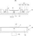
도 1을 참조하면, 본 발명의 일 실시예에 따른 표시 장치의 제조 장치(100)는 지그 회전축(110)과, 제1 지그(120) 및 제2 지그(130)를 포함한다.Referring to FIG. 1 , the display
지그 회전축(110)은 제1 지그(120)에 설치될 수 있는데, 바람직하게는 제1 지그(120)의 무게중심에 인접하도록 설치될 수 있다. 하지만, 본 발명의 실시예들은 이에 한정되지 않으며, 지그 회전축(110)은 제1 지그(120)의 모든 영역에 설치가 가능하다. 다만, 지그 회전축(110)은 제1 지그(120)를 회전시키는 동시에 제1 지그를 지지하는 역할도 부수적으로 수행하므로, 제1 지그(120)의 무게중심에서 먼 곳에 설치될 경우 제1 지그(120)의 무게에 의해 지그 회전축(110)에 피로 변형이 일어날 가능성도 배제할 수 없으므로, 바람직하게는 제1 지그(120)의 무게중심에 인접한 위치에 설치될 수 있다. 한편, 후술하겠으나 지그 회전축(110)은 제1 지그(120)의 일단부에 설치될 수도 있다. 이러한 구조는 이하 도 8 및 도 9를 참조하여 상세히 후술하기로 하고, 이하에서는 지그 회전축(110)이 제1 지그(120)에 설치된 경우를 중심으로 상세히 설명하기로 한다.The
또한, 지그 회전축(110)에는 지그 회전축(110)을 회전시키는 구동력을 제공하는 회전구동부(140)와, 제1 지그(120)를 승강시키는 구동력을 제공하는 승강구동부(150)가 설치될 수도 있다. 도 1은 설명의 편의를 위해 회전구동부(140)와 승강구동부(150)가 모두 지그 회전축(110)에 인접하도록 설치된 모습을 나타내나, 본 발명의 실시예들은 이에 한정되지 않는다. 즉, 회전구동부(140)는 지그 회전축(110)에 회전 구동력을 제공하는 역할을 수행할 뿐, 그 설치 위치는 어느 한 곳에 한정되지 않는다. 마찬가지로, 승강구동부(150) 또한 제1 지그(120)를 승강시키는 구동력을 제공하는 역할을 수행한다면 그 어떠한 위치에 설치될 수도 있다. 중요한 점은, 회전구동부(140)와 승강구동부(150)는 지그 회전축(110)과 기구적으로 연결되어 지그 회전축(110)에 회전 구동력과 승강 구동력을 제공하는 기능을 수행하는 것이며, 그 설치 위치는 어느 한 곳에 한정되지 않는다.In addition, the
상세히, 회전구동부(140) 및 승강구동부(150)는 다양한 장치를 포함할 수 있다. 예를 들면, 회전구동부(140)와 승강구동부(150)는 공압이나 유압 등으로 작동하여 제1 지그(120)를 회전시키거나 승강시키는 실린더일 수 있으며, 또한 전기에너지로 작동하는 모터를 포함할 수도 있다.In detail, the rotation drive unit 140 and the lifting drive unit 150 may include various devices. For example, the rotation drive unit 140 and the lifting drive unit 150 may be cylinders that operate with pneumatic or hydraulic pressure to rotate or raise the
제1 지그(120)는 커버윈도우(W)가 안착되는 안착부(121)와, 안착부(121)의 적어도 일측에 배치되어 커버윈도우(W)의 출입을 허용하는 제1 위치(도 2 참조)와, 커버 윈도우를 고정하는 제2 위치(도 3 참조) 사이에서 회전 가능한 지지부(122)를 포함한다. 또한, 제1 지그(120)는 지그 회전축(110)을 중심으로 시계 방향 또는 반시계 방향으로 회전할 수 있도록 배치될 수 있다.The
상세히, 안착부(121)는 커버윈도우(W)와 형상이 유사할 수 있다. 특히, 안착부(121)의 적어도 일부는 곡면으로 형성될 수 있다. 즉, 안착부(121)는 제1 지그(120)가 제2 위치에 위치하는 경우(도 3 참조), 적어도 일부가 제1 지그(120)를 기준으로 제2 지그(130)에서 멀어지는 방향(도 3의 상측)으로 인입되도록 형성될 수 있다. 이는, 적어도 일부가 곡면으로 형성되는 커버윈도우(W)를 안착부(121)에 밀착시킴으로써, 후술할 커버윈도우(W)에 패널부재(P)를 부착하는 공정에서 커버윈도우(W)에 변형이 일어나거나 파손되는 위험을 방지하기 위함이다.In detail, the
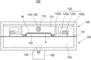
또한, 지지부(122)는 시소 회전축(122a)과, 시소 회전축(122a)을 중심으로 회전 가능한 시소 가이드(122b)와, 시소 가이드(122b)의 일측에 부착되어 시소 가이드(122b)의 일측에 중력을 전달하는 질량체(122c)를 포함할 수 있다. 상세히, 질량체(122c)는 소정의 무게를 갖는 물체로써, 도 2와 도 3에 나타난 바와 같이 제1 지그(120)가 회전함에 따라 지지부(122)가 회전할 수 있도록 지지부(122)의 일측에 충분한 무게를 전달할 수 있도록 구성됨이 바람직하다.In addition, the
여기서, "충분한 무게"라 함은, 도 2의 경우 질량체(122c)의 무게에 의해 좌측의 지지부(122)가 시소 회전축(122a)을 중심으로 반시계 방향으로, 우측의 지지부(122)가 시소 회전축(122a)을 중심으로 시계 방향으로 회전할 수 있을 만큼의 무게를 의미하며, 도 3의 경우 질량체(122c)의 무게에 의해 지지부(122)가 시소 회전축(122a)을 중심으로 회전할 수 있을 만큼의 무게를 의미한다. 더 상세히는, 질량체(122c)의 무게는 시소 회전축(122a)과 시소 가이드(122b) 사이의 정지마찰력을 극복할 수 있을 만큼의 무게로 구성됨이 바람직하다.Here, “sufficient weight” means that in the case of FIG. 2, the
한편, 본 발명의 실시예들에 따른 표시 장치의 제조 장치는 제1 지그(120)의 좌측과 우측에 각각 하나씩의 지지부(122)가 설치된 모습을 나타내나, 본 발명의 실시예들은 이에 한정되지 않는다. 즉, 도면에 도시하지는 않았으나 지지부(122)는 제1 지그(120)의 좌측 및 우측 중 적어도 일측에 설치될 수 있다. 만약 지지부(122)가 제1 지그(120)의 좌측 및 우측 중 적어도 일측에 설치되는 경우, 지지부(122)가 설치되지 않은 제1 지그(120)의 타측에는 도면에 나타난 지지부(122)와 실질적으로 동일한 형태의 고정부(미도시)가 설치될 수 있으며, 이러한 고정부는 안착부(121)에 커버윈도우(W)가 안착되어 도 3에 나타난 바와 같이 커버윈도우(W)와 패널부재(P)가 마주볼 경우 커버윈도우(W)가 하측으로 낙하하지 않도록 고정하는 역할을 수행할 수 있다. 다만, 이하에서는 설명의 편의를 위해 제1 지그(120)의 좌측 및 우측에 각각 하나씩의 지지부(122)가 설치된 경우를 중심으로 설명하기로 한다.Meanwhile, the display device manufacturing apparatus according to the embodiments of the present invention shows one
한편, 시소 회전축(122a)에는 지그 회전축(110)에 연결 및 설치되는 회전구동부(140)와 같은 구성이 설치되지 않는다. 즉, 시소 회전축(122a)은 시소 가이드(122b)가 회전하는 회전 중심의 기능을 수행할 뿐, 시소 가이드(122b)를 회전시키는 구동력을 제공하지는 않는다. 대신, 시소 가이드(122b)는 별도의 구동부(미도시) 없이도 제1 지그(120)가 제1 위치(도 2 참조)에서 제2 위치(도 3 참조)를 왕복함에 따라 함께 회전할 수 있으며, 구체적으로는 질량체(122c)가 배치된 시소 가이드(122b)의 일측과 시소 회전축(122a)을 기준으로 반대편인 시소 가이드(122b)의 타측은 질량체(122c)의 이동 방향과 반대 방향으로 이동할 수 있다.Meanwhile, a component such as the rotation drive unit 140 connected to and installed on the
즉, 제1 지그(120)가 제1 위치(도 2 참조)에 위치한 경우, 시소 가이드(122b)의 타측은 질량체(122c)가 설치된 시소 가이드(122b)의 일측이 하측으로 이동함에 따라 시소 회전축(122a)을 기준으로 반대 방향인 상측으로 이동할 수 있다. 이러한 경우, 시소 가이드(122b)의 타측은 안착부(121)를 개방하여 안착부(121)에 커버윈도우(W)를 안착시킬 수 있다. 반면, 제1 지그(120)가 제2 위치에 위치할 경우(도 3 참조), 시소 가이드(122b)의 타측은 질량체(122c)가 설치된 시소 가이드(122b)의 일측이 하측으로 이동함에 따라 시소 회전축(122a)을 기준으로 반대 방향인 상측으로 이동하여 안착부(121)에 접촉할 수 있다.That is, when the
상세히, 제1 지그(120)가 제2 위치에 위치한 경우(도 3 참조), 시소 가이드(122b)의 타측 말단부는 안착부(121)의 양단 뿐만 아니라, 안착부(121)에 안착된 커버윈도우(W)의 양단과 접촉하여 커버윈도우(W)가 하측 방향으로 낙하하지 않도록 방지할 수 있다.In detail, when the
한편, 지지부(122)는 시소 가이드(122b)의 타측에 설치되는 비점착코팅부(122d)를 더 포함할 수 있다. 비점착코팅부(122d)는 도 3에 나타난 바와 같이 시소 가이드(122b)의 타측이 커버윈도우(W)와 접촉하는 경우 직접적으로 커버윈도우(W)와 접촉하는 부분으로, 반복되는 공정에서 이물질이나 오염물질이 커버윈도우(W)로 침투하지 않도록 방지할 수 있다.Meanwhile, the
제2 지그(130)는 내부 공간(IDa)을 밀폐하도록 설치되어 패널부재(P)가 안착되는 탄성막(131)을 구비하고, 제1 지그(120)가 제2 위치에 위치한 경우(도 3 참조), 안착부(121)와 대향하도록 설치될 수 있다. 도면에 도시되지는 않았으나, 제2 지그(130)에도 제1 지그(120)에 설치된 승강구동부(150)와 유사한 구동부(미도시)가 설치될 수 있다. 즉, 도면은 제1 지그(120)가 제2 지그(130)에 대해 승강 운동하는 것으로 묘사하고 있으나, 본 발명의 실시예들은 이에 한정되지 않으며, 제2 지그(130) 또한 별도의 구동부(미도시)에 연결되어 제1 지그(120)에 대해 승강 가능하도록 구성될 수도 있다. 이하에서는 설명의 편의를 위해, 제1 지그(120)에만 승강구동부(150)가 설치된 경우를 중심으로 설명하기로 한다.The
또한, 제2 지그(130)는 제2 지그(130)의 내부 공간(IDa)과 외부를 연결하는 제1 홀(132)을 더 포함할 수 있다. 그리고, 제1 홀(132)에는 제2 지그(130)의 내부 공간(IDa)의 공기를 흡인하거나, 제2 지그(130)의 내부 공간(IDa)에 공기를 주입하는 제1 펌프(160)가 설치될 수 있다. 예를 들면, 제1 펌프(160)는 제2 지그(130)의 내부 공간(IDa)을 진공 상태로 만들 수 있는 진공 펌프일 수 있다.Additionally, the
마찬가지로, 도면에 나타나지는 않았으나 제1 지그(120) 또한 제1 지그(120)의 내부 공간(미표기)과 외부를 연통하는 제2 홀(미도시)을 포함할 수 있다. 또한, 제2 홀에는 제1 지그(120)의 내부 공간의 공기를 흡인하거나, 제1 지그(120)의 내부 공간에 공기를 주입하는 제2 펌프(미도시)가 설치될 수 있다. 제2 펌프 또한, 제1 펌프와 마찬가지로 제1 지그(120)의 내부 공간을 진공 상태로 만들 수 있는 진공 펌프일 수 있다.Likewise, although not shown in the drawing, the
상기와 같은 구성을 갖는 표시 장치의 제조 장치(100)에 의하면, 커버윈도우(W)와 패널부재(P)의 부착 공정 시 커버윈도우(W)를 간편하게 고정시킬 수 있으며, 패널부재(P)에 미리 접착되어 있는 접착층(AD)을 커버윈도우(W)에 정밀하게 부착할 수 있으므로, 간단한 구성으로도 곡면 형상을 갖는 표시 장치(미표기)를 신속하고 용이하게 생산할 수 있으며, 또한 불량율을 최소화할 수 있다.According to the display
다음으로, 도 2 내지 도 7을 참조하여 표시 장치의 제조 장치(100)를 이용하여 표시 장치를 제조하는 방법에 대해 상세하게 후술하기로 한다.Next, a method of manufacturing a display device using the display
먼저, 표시 장치를 제조하기 위하여 커버윈도우(W)를 가공할 수 있다. 커버윈도우(W)는 다양한 소재의 물질을 포함할 수 있는데, 예를 들면 커버윈도우(W)는 글라스(glass) 또는 플라스틱(plastic)을 포함할 수 있다. 이외에도, 커버윈도우(W)는 상기에 한정되지 않으며, 적어도 일부를 굴곡지게 형성할 수 있는 모든 물질을 포함할 수 있다. 여기서, "적어도 일부"라 함은, 도면에 도시된 커버윈도우(W)와 같이 양단이 굴곡진 형태에 한정되지 않는다는 의미로, 예를 들어 그 단면이 호 형상이나 원 형상과 같이 커버윈도우(W) 전체가 굴곡진 형태로 형성될 수도 있음을 의미한다. 다만, 이하에서는 설명의 편의를 위하여 커버윈도우(W)의 양단이 굴곡진 형태로 형성된 경우를 중심으로 설명하기로 한다.First, the cover window (W) can be processed to manufacture the display device. The cover window W may include various materials. For example, the cover window W may include glass or plastic. In addition, the cover window W is not limited to the above, and may include any material that can form at least a portion of the cover window W to be curved. Here, “at least a portion” means that it is not limited to a shape with both ends curved like the cover window (W) shown in the drawing. For example, the cover window (W) has a cross section such as an arc shape or a circle shape. ) This means that the whole thing can be formed in a curved shape. However, for convenience of explanation, the following description will focus on the case where both ends of the cover window (W) are formed in a curved shape.
상기와 같이 커버윈도우(W)의 제조가 진행되는 동안 또는 완료된 이후, 패널부재(P)를 제조할 수 있다. 패널부재(P)는 일반적인 표시패널일 수 있으며, 또는 터치패널(touch screen panel, TSP)일 수도 있다. 이와 같은 패널부재(P)를 제조하는 방법은 일반적인 패널부재(P)의 제조 방법과 동일하므로 상세한 설명은 생략하기로 한다.As described above, the panel member (P) can be manufactured while the manufacturing of the cover window (W) is in progress or after it is completed. The panel member P may be a general display panel or a touch screen panel (TSP). Since the method of manufacturing such a panel member (P) is the same as the manufacturing method of a general panel member (P), detailed description will be omitted.
커버윈도우(W)와 패널부재(P)의 준비가 완료되면, 패널부재(P)의 일측에 접착층(AD)을 도포할 수 있다. 상세히, 접착층(AD)은 필름(film) 형태로 형성되어 패널부재(P)에 부착될 수 있으며, 또는 소정의 점성을 갖는 유체의 형태로 패널부재(P) 상에 도포되는 것도 가능하다. 다만, 이하에서는 설명의 편의를 위하여 접착층(AD)이 필름 형태로 형성되는 경우를 중심으로 상세히 설명하기로 한다.When preparation of the cover window (W) and the panel member (P) is completed, the adhesive layer (AD) can be applied to one side of the panel member (P). In detail, the adhesive layer AD may be formed in the form of a film and attached to the panel member P, or may be applied on the panel member P in the form of a fluid having a predetermined viscosity. However, for convenience of explanation, hereinafter, the detailed description will focus on the case where the adhesive layer AD is formed in the form of a film.
도 2는 제1 지그(120)의 지지부(122)가 커버윈도우(W)의 출입을 허용하는 제1 위치에 위치한 경우를 나타낸다.FIG. 2 shows a case where the
도 2를 참조하면, 상기와 같이 패널부재(P) 상에 접착층(AD)을 부착한 이후, 커버윈도우(W)를 제1 지그(120)에, 패널부재(P)를 제2 지그(130)에 안착시킬 수 있다. 상세히, 적어도 일부가 굴곡지게 형성되는 안착부(121)를 갖는 제1 지그(120)에 안착부(121)의 형상에 대응하는 형상을 갖는 커버윈도우(W)를 배치할 수 있다. 또한, 제2 지그(130)의 탄성막(131) 상에 패널부재(P)를 배치할 수 있다. 또한, 별도로 도면에 도시하지는 않았으나, 패널부재(P)를 탄성막(131) 상에 배치하기 이전에, 패널부재(P) 상에 접착층(AD)을 도포하는 단계를 거칠 수 있다.Referring to FIG. 2, after attaching the adhesive layer (AD) on the panel member (P) as above, the cover window (W) is attached to the first jig (120) and the panel member (P) is attached to the second jig (130). ) can be placed. In detail, a cover window (W) having a shape corresponding to the shape of the
한편, 지지부(122)의 작동에 대해 더 상세히 설명하면, 질량체(122c)가 배치된 시소 가이드(122b)의 일측은 질량체(122c)의 무게에 의해 하측으로 이동할 수 있다. 이에 따라, 시소 가이드(122b)의 타측은 시소 회전축(122a)을 기준으로 상측으로 이동할 수 있다. 이와 같이, 시소 가이드(122b)의 타측이 질량체(122c)의 이동 방향과 반대 방향으로 이동할 경우, 즉 시소 가이드(122b)의 타측이 상측으로 이동할 경우에는 시소 가이드(122b)가 안착부(121)를 개방함으로써 안착부(121)에 커버윈도우(W)를 용이하게 안착시킬 수 있는 통로가 형성될 수 있다.Meanwhile, if the operation of the
다음으로, 도 3은 제1 지그(120)의 지지부(122)가 커버윈도우(W)를 고정하는 제2 위치에 위치한 모습으로, 도 2의 제1 지그(120)가 지그 회전축(110)을 중심으로 180도 회전한 모습을 나타낸다. 제1 지그(120)의 이러한 구동에 의해, 제1 지그(120)에 안착된 커버윈도우(W)와 제2 지그(130)의 탄성막(131) 상에 배치된 패널부재(P)가 대향하도록 배치될 수 있다. 한편, 도면에 도시되지는 않았으나 제1 지그(120)를 회전하여 커버윈도우(W) 및 패널부재(P)가 대향하도록 배치하는 단계 이후에, 제1 지그(120) 및 제2 지그(130) 중 적어도 하나를 이동하여 커버윈도우(W)와 패널부재(P)를 정렬하는 단계를 더 포함할 수도 있다. 예를 들면, 도 3의 수평방향으로 제1 지그(120) 및 제2 지그(130) 중 적어도 하나를 이동하여 커버윈도우(W)와 패널부재(P)를 수직방향을 기준으로 정확하게 정렬시킬 수 있다.Next, FIG. 3 shows the
도 3을 참조하여 지지부(122)의 작동에 대해 설명하면, 질량체(122c)가 배치된 시소 가이드(122b)의 일측은 질량체(122c)의 무게에 의해 하측으로 이동할 수 있다. 이에 따라, 시소 가이드(122b)의 타측은 시소 회전축(122a)을 기준으로 상측으로 이동할 수 있다. 이와 같이, 시소 가이드(122b)의 타측이 질량체(122c)의 이동 방향과 반대 방향으로 이동할 경우, 시소 가이드(122b)의 타측은 안착부(121)와 커버윈도우(W)와 접촉하여 커버윈도우(W)를 고정함으로써, 커버윈도우(W)가 하측으로 낙하하는 것을 방지할 수 있다.When the operation of the
상술한 지지부(122)의 작동에 의하면, 시소 회전축(122a)을 회전시킬 수 있는 별도의 구동부(미도시)를 지지부(122)에 연결하지 않고도 커버윈도우(W)를 간단히 고정할 수 있으므로 표시 장치의 제조 장치(100)의 작업 부하를 감소시킬 수 있다.According to the operation of the
다음으로, 도 4는 제1 지그(120)가 제2 지그(130) 측으로 하강하여 제1 지그(120)와 제2 지그(130)가 서로 결합함으로써, 제1 지그(120) 및 제2 지그(130)의 내부를 밀폐하는 모습을 나타낸다. 또한, 도 4는 제1 펌프(160)를 작동시켜 탄성막(131)으로 밀폐된 제2 지그(130)의 내부 공간(IDa)의 공기를 흡인함으로써, 제2 지그(130)의 내부 공간(IDa)을 진공 상태로 감압하는 모습을 나타낸다.Next, Figure 4 shows that the
여기서, 도 4는 제1 지그(120)가 제2 지그(130) 측으로 하강하는 모습만을 나타내나, 이는 설명의 편의를 위한 것으로, 본 발명의 실시예들은 이에 한정되지 않는다. 즉, 반대로 제2 지그(130)가 제1 지그(120) 측으로 상승할 수도 있으며, 또한 제1 지그(120)와 제2 지그(130)가 동시에 하강 및 상승함으로써 제1 지그(120)와 제2 지그(130)가 서로 결합될 수도 있다.Here, FIG. 4 only shows the
또한, 도면에 나타나지는 않았으나, 제1 지그(120)에도 제2 지그(130)에 형성된 제1 홀(132)과 같이 제1 지그(120)의 내부 공간(IDb)과 외부를 연통하는 제2 홀(미도시)이 형성될 수 있다. 그리고, 이러한 제2 홀에는 제2 홀에 연결되어 제1 지그(120)의 내부 공간(IDb)의 공기를 흡인하거나, 제1 지그(120)의 내부 공간(IDb)에 공기를 주입하는 제2 펌프(미도시)가 연결될 수 있다. 즉, 도면에는 제2 지그(130)에 연결된 제1 펌프(160)가 제1 홀(132)을 통해 제2 지그(130)의 내부 공간(IDa)에 잔존하는 공기를 흡인하여 제2 지그(130)의 내부 공간(IDa)을 진공 상태로 감압하는 모습만이 도시되어 있으나, 이는 설명의 편의를 위한 것으로, 제1 지그(120) 또한 제2 펌프에 연결됨으로써 제1 지그(120)의 내부 공간(IDb)을 진공 상태로 감압할 수 있다. 이렇게 제1 지그(120)의 내부 공간(IDb)을 진공 상태로 감압함으로써, 이후 커버윈도우(W)와 패널부재(P)의 부착 공정에서 이물질이나 기포가 커버윈도우(W)와 패널부재(P) 사이에 침투하는 것을 방지할 수 있다.In addition, although not shown in the drawing, the
다음으로, 도 5는 제2 지그(130)의 내부를 가압하여 커버윈도우(W)와 패널부재(P)를 부착하는 모습을 나타낸다. 도면에 나타난 바와 같이, 제1 펌프(160)는 제1 홀(132)을 통해 제2 지그(130)의 내부 공간(IDa)에 공기를 주입할 수 있으며, 이에 따라 탄성막(131)이 제1 지그(120) 측으로 팽창할 수 있다. 탄성막(131)이 제1 지그(120) 측으로 팽창함에 따라, 탄성막(131) 상에 배치된 패널부재(P)는 커버윈도우(W) 측으로 접근하게 되고, 결국에는 커버윈도우(W)의 일면에 부착될 수 있다.Next, Figure 5 shows the cover window (W) and the panel member (P) being attached by pressing the inside of the
상세히, 패널부재(P)는 탄성막(131)에 평평하게 배치되나, 패널부재(P)가 커버윈도우(W)에 부착되는 경우 커버윈도우(W)의 형상에 따라 패널부재(P)의 적어도 일부는 굴곡된 상태로 커버윈도우(W)에 부착될 수 있다.In detail, the panel member (P) is disposed flat on the
다음으로, 도 6은 패널부재(P)와 커버윈도우(W)의 부착이 완료된 이후 제2 지그(130)의 내부 공간(IDa)에 주입된 공기를 다시 외부로 흡인하는 모습을 나타낸다. 여기서, 제1 펌프(160)는 제1 홀(132)을 통해 제2 지그(130)의 내부 공간(IDa)에 잔존하는 공기를 흡인할 수 있다. 이렇게 제2 지그(130)의 내부 공간(IDa)의 공기가 외부로 배출되면, 탄성막(131)은 다시 수축하여 원래 형상으로 복원될 수 있다.Next, Figure 6 shows the air injected into the internal space (IDa) of the
도 7은 제2 지그(130)의 내부 공간(IDa)에 잔존하는 공기를 외부로 배출하여 탄성막(131)을 원래 형상으로 복원한 이후, 제1 지그(120)를 다시 상측으로 상승시키고, 제1 지그(120)를 회전하여 다시 안착부(121)를 개방한 모습을 나타낸다. 이후, 도면에 나타나지는 않았으나 서로 부착된 패널부재(P)와 커버윈도우(W)를 외부로 반출할 수 있다.Figure 7 shows that after the air remaining in the internal space (IDa) of the
도 8은 본 발명의 다른 실시예에 따른 표시 장치의 제조 장치를 개략적으로 나타내는 개념도이고, 9는 도 8의 표시 장치의 제조 장치의 작동 상태를 나타내는 작동도이다.FIG. 8 is a conceptual diagram schematically showing a display device manufacturing apparatus according to another embodiment of the present invention, and FIG. 9 is an operational diagram showing an operating state of the display device manufacturing apparatus of FIG. 8 .
도 8 및 도 9를 참조하면, 전술한 바와 같이 지그 회전축(210)은 제1 지그(220)와 제2 지그(230)의 일단부에 설치되어 제1 지그(220)와 제2 지그(230)를 서로 힌지 결합할 수도 있다.Referring to FIGS. 8 and 9 , as described above, the
도 8은 제1 지그(220)의 지지부(222)가 커버윈도우(도 2의 W 참조)의 출입을 허용하는 제1 위치에 제1 지그(220)가 위치한 모습을 나타내고, 도 9는 제1 지그(220)의 지지부(222)가 커버윈도우를 고정할 수 있는 제2 위치에 제1 지그(220)가 위치한 모습을 나타낸다. 즉, 도 9는 제1 지그(220)의 제1 위치에서, 시소 회전축(210)에 설치된 회전구동부(240)가 작동하여 제1 지그(220)를 시계 방향으로 회전시킴으로써 제1 지그(220)를 제2 위치로 이동한 모습을 나타낸다.Figure 8 shows the
도 8과 도 9에 도시된 안착부(221)와, 시소 회전축(222a), 시소 가이드(222b), 질량체(222c) 및 비점착코팅부(222d)를 포함하는 지지부(222)와, 탄성막(231)과, 제1 홀(232)과 제1 펌프(260)와 같은 구성은 도 1 내지 도 7에서 전술한 내용과 동일하므로 여기서는 자세한 설명은 생략하기로 한다.A
상기와 같은 구성에 의한 표시 장치의 제조 장치(100)(200)와 이를 이용한 표시 장치의 제조 방법에 따르면, 곡면 형상을 갖는 표시 장치를 신속하고 정확하게 제조함으로써 불량률을 최소화할 수 있으며, 간단한 구성으로도 커버윈도우(W)를 고정할 수 있어 작업 부하를 줄이는 동시에 전체적인 장치의 구비를 위한 비용을 절약할 수 있다.According to the display device manufacturing apparatus 100 (200) having the above configuration and the display device manufacturing method using the same, the defect rate can be minimized by quickly and accurately manufacturing a display device having a curved shape and with a simple configuration. The cover window (W) can also be fixed, reducing the workload and saving costs for the overall device.
이와 같이 본 발명은 도면에 도시된 일 실시예를 참고로 하여 설명하였으나 이는 예시적인 것에 불과하며 당해 분야에서 통상의 지식을 가진 자라면 이로부터 다양한 변형 및 실시예의 변형이 가능하다는 점을 이해할 것이다. 따라서, 본 발명의 진정한 기술적 보호 범위는 첨부된 특허청구범위의 기술적 사상에 의하여 정해져야 할 것이다.As such, the present invention has been described with reference to an embodiment shown in the drawings, but this is merely an example, and those skilled in the art will understand that various modifications and variations of the embodiment are possible therefrom. Therefore, the true scope of technical protection of the present invention should be determined by the technical spirit of the attached patent claims.
100: 표시 장치의 제조 장치 130: 제2 지그
110: 지그 회전축 140: 회전구동부
120: 제1 지그 150: 승강구동부
121: 안착부 160: 제1 펌프
122: 지지부100: Display device manufacturing device 130: Second jig
110: Jig rotation axis 140: Rotation drive unit
120: 1st jig 150: Elevating drive eastern part
121: Seating part 160: First pump
122: support part
Claims (19)
Translated fromKorean제2 지그에 패널부재를 배치하는 단계;
상기 커버윈도우 및 상기 패널부재가 대향하도록 상기 제1 지그를 회전하는 단계; 및
상기 제1 지그 및 상기 제2 지그 중 적어도 하나를 승강하여 상기 커버윈도우와 상기 패널부재를 부착하는 단계;를 포함하고,
상기 제1 지그를 회전하는 단계는,
시소 회전축과, 상기 시소 회전축을 중심으로 회전하는 시소 가이드와, 상기 시소 가이드에 배치되어 상기 시소 가이드의 일측에 중력을 전달하는 질량체를 포함하는 지지부가 상기 제1 지그의 회전에 따라 함께 회전하며, 상기 시소 가이드의 타측은 상기 제1 지그의 회전에 따라 상기 질량체의 이동 방향과 반대 방향으로 이동하여 상기 커버윈도우의 적어도 일측에 접촉함으로써 상기 커버윈도우를 고정하는 단계를 포함하는, 표시 장치의 제조 방법.Placing a cover window having a shape corresponding to the shape of the seating portion on a first jig having a seating portion of which at least a portion is formed to be curved;
Placing a panel member on a second jig;
rotating the first jig so that the cover window and the panel member face each other; and
A step of attaching the cover window and the panel member by lifting at least one of the first jig and the second jig,
The step of rotating the first jig is,
A support portion including a seesaw rotation axis, a seesaw guide rotating around the seesaw rotation axis, and a mass disposed on the seesaw guide and transmitting gravity to one side of the seesaw guide rotates together with the rotation of the first jig, A method of manufacturing a display device comprising the step of fixing the cover window by moving the other side of the seesaw guide in a direction opposite to the movement direction of the mass according to the rotation of the first jig and contacting at least one side of the cover window. .
상기 제2 지그에 패널부재를 배치하는 단계는,
상기 패널부재 상에 점착층을 도포하는 단계를 포함하는, 표시 장치의 제조 방법.According to claim 1,
The step of placing the panel member on the second jig is:
A method of manufacturing a display device, comprising the step of applying an adhesive layer on the panel member.
상기 커버윈도우 및 상기 패널부재가 대향하도록 상기 제1 지그를 회전하는 단계 이후에,
상기 제1 지그 및 상기 제2 지그 중 적어도 하나를 이동하여 상기 커버윈도우와 상기 패널부재를 정렬하는 단계를 더 포함하는, 표시 장치의 제조 방법.According to claim 1,
After rotating the first jig so that the cover window and the panel member face each other,
The method of manufacturing a display device further comprising aligning the cover window and the panel member by moving at least one of the first jig and the second jig.
상기 커버윈도우와 상기 패널부재를 부착하는 단계는,
상기 제1 지그와 상기 제2 지그를 결합하여 상기 제1 지그 및 상기 제2 지그의 내부를 밀폐하는 단계를 포함하는, 표시 장치의 제조 방법.According to claim 1,
The step of attaching the cover window and the panel member is,
A method of manufacturing a display device, comprising the step of combining the first jig and the second jig to seal the insides of the first jig and the second jig.
상기 커버윈도우와 상기 패널부재를 부착하는 단계는,
상기 제1 지그 및 상기 제2 지그의 내부를 밀폐하는 단계 이후에,
상기 제1 지그 및 상기 제2 지그의 내부를 진공 상태로 감압하는 단계를 더 포함하는, 표시 장치의 제조 방법.According to clause 4,
The step of attaching the cover window and the panel member is,
After sealing the interior of the first jig and the second jig,
A method of manufacturing a display device, further comprising depressurizing the interior of the first jig and the second jig to a vacuum state.
상기 커버윈도우와 상기 패널부재를 부착하는 단계는,
상기 제1 지그 및 상기 제2 지그의 내부를 진공 상태로 감압하는 단계 이후에,
상기 제2 지그의 내부를 가압하여 상기 제2 지그에 설치된 탄성막을 팽창시킴으로써 상기 패널부재를 상기 커버윈도우 측으로 이동시키는 단계를 더 포함하는, 표시 장치의 제조 방법.According to clause 5,
The step of attaching the cover window and the panel member is,
After depressurizing the interior of the first jig and the second jig to a vacuum state,
The method of manufacturing a display device further comprising moving the panel member toward the cover window by pressurizing the inside of the second jig to expand an elastic film installed in the second jig.
상기 패널부재는 상기 탄성막에 평평하게 배치되고,
상기 제2 지그의 내부를 가압하여 상기 패널부재를 상기 커버윈도우 측으로 이동시키는 단계에서, 상기 패널부재의 적어도 일부는 굴곡되어 상기 커버윈도우에 부착되는, 표시 장치의 제조 방법.According to clause 6,
The panel member is disposed flat on the elastic membrane,
In the step of moving the panel member toward the cover window by pressing the inside of the second jig, at least a portion of the panel member is bent and attached to the cover window.
커버윈도우가 안착되는 안착부와, 상기 안착부의 적어도 일측에 배치되어 상기 커버윈도우의 출입을 허용하는 제1 위치와, 상기 커버윈도우를 고정하는 제2 위치 사이에서 회전 가능한 지지부를 구비하고, 상기 지그 회전축을 중심으로 회전 가능하도록 배치되는 제1 지그; 및
상기 제1 지그가 상기 제2 위치에 위치한 경우 상기 안착부와 대향하도록 배치되는 제2 지그;를 포함하고,
상기 지지부는,
시소 회전축과,
상기 시소 회전축을 중심으로 회전 가능한 시소 가이드와,
상기 시소 가이드의 일측에 부착되어 상기 시소 가이드의 상기 일측에 중력을 전달하는 질량체를 포함하되,
상기 시소 가이드의 타측은 상기 제1 지그가 상기 제2 위치에 위치한 경우, 상기 질량체의 무게에 의해 상기 안착부에 접촉하는 방향으로 이동하여 상기 커버윈도우를 고정하는, 표시 장치의 제조 장치.Jig rotation axis;
It has a seating part on which the cover window is seated, a support part rotatable between a first position disposed on at least one side of the seating part to allow entry and exit of the cover window, and a second position for fixing the cover window, and the jig A first jig arranged to be rotatable about a rotation axis; and
A second jig disposed to face the seating portion when the first jig is located at the second position,
The support part,
Seesaw rotation axis,
A seesaw guide rotatable about the seesaw rotation axis,
Includes a mass attached to one side of the seesaw guide and transmitting gravity to the one side of the seesaw guide,
When the first jig is located at the second position, the other side of the seesaw guide moves in a direction to contact the seating portion due to the weight of the mass body to fix the cover window.
상기 지그 회전축은 제1 지그에 설치되는, 표시 장치의 제조 장치.According to clause 8,
An apparatus for manufacturing a display device, wherein the jig rotation axis is installed in a first jig.
상기 지그 회전축은 상기 제1 지그 및 상기 제2 지그의 일단부에 설치되고,
상기 제1 지그 및 상기 제2 지그는 서로 힌지(hinge) 결합되는, 표시 장치의 제조 장치.According to clause 8,
The jig rotation axis is installed at one end of the first jig and the second jig,
The first jig and the second jig are hinged to each other.
상기 지그 회전축을 회전시키는 구동력을 제공하는 회전구동부를 더 포함하는, 표시 장치의 제조 장치.According to clause 8,
An apparatus for manufacturing a display device, further comprising a rotation driver that provides a driving force to rotate the jig rotation axis.
상기 제1 지그 및 상기 제2 지그 중 적어도 하나를 승강시키는 구동력을 제공하는 승강구동부를 더 포함하는, 표시 장치의 제조 장치.According to clause 8,
The apparatus for manufacturing a display device further includes a lifting drive unit that provides a driving force to lift at least one of the first jig and the second jig.
상기 지지부는 상기 시소 가이드의 타측에 설치되는 비점착코팅부를 더 포함하는, 표시 장치의 제조 장치.According to clause 8,
The support portion further includes a non-adhesive coating portion installed on the other side of the seesaw guide.
상기 제2 지그는 상기 제2 지그의 내부 공간을 밀폐하도록 설치되어 패널부재를 안착시키는 탄성막을 포함하는, 표시 장치의 제조 장치.According to clause 8,
The second jig is installed to seal the internal space of the second jig and includes an elastic film to seat the panel member.
상기 제2 지그는 상기 제2 지그의 내부 공간과 외부를 연통하는 제1 홀을 포함하는, 표시 장치의 제조 장치.According to clause 8,
The second jig is a display device manufacturing apparatus including a first hole communicating with an interior space of the second jig and an exterior.
상기 제1 홀에 연결되어 상기 제2 지그의 내부 공간의 공기를 흡인하거나, 상기 제2 지그의 내부 공간에 공기를 주입하는 제1 펌프를 더 포함하는, 표시 장치의 제조 장치.According to claim 15,
The apparatus for manufacturing a display device further includes a first pump connected to the first hole and sucking air into the inner space of the second jig or injecting air into the inner space of the second jig.
상기 제1 지그는 상기 제1 지그의 내부 공간과 외부를 연통하는 제2 홀을 더 포함하는, 표시 장치의 제조 장치.According to clause 8,
The first jig further includes a second hole communicating with an interior space of the first jig and an exterior of the first jig.
상기 제2 홀에 연결되어 상기 제1 지그의 내부 공간의 공기를 흡인하거나, 상기 제1 지그의 내부 공간에 공기를 주입하는 제2 펌프를 더 포함하는, 표시 장치의 제조 장치.According to claim 17,
The apparatus for manufacturing a display device further includes a second pump connected to the second hole and sucking air into the inner space of the first jig or injecting air into the inner space of the first jig.
상기 안착부는, 상기 제1 지그가 상기 제2 위치에 위치하는 경우, 적어도 일부가 상기 제1 지그를 기준으로 상기 제2 지그에서 멀어지는 방향으로 인입되도록 형성되는, 표시 장치의 제조 장치.According to clause 8,
The apparatus for manufacturing a display device, wherein when the first jig is located at the second position, at least a portion of the seating portion is formed to be retracted in a direction away from the second jig with respect to the first jig.
Priority Applications (3)
| Application Number | Priority Date | Filing Date | Title |
|---|---|---|---|
| KR1020160122380AKR102638297B1 (en) | 2016-09-23 | 2016-09-23 | Manufacturing method and apparatus for a display device |
| US15/713,101US10399321B2 (en) | 2016-09-23 | 2017-09-22 | Apparatus for manufacturing a display device and a method using the same |
| CN201710863817.5ACN107870693B (en) | 2016-09-23 | 2017-09-22 | Apparatus for manufacturing a display device and method of using the same |
Applications Claiming Priority (1)
| Application Number | Priority Date | Filing Date | Title |
|---|---|---|---|
| KR1020160122380AKR102638297B1 (en) | 2016-09-23 | 2016-09-23 | Manufacturing method and apparatus for a display device |
Publications (2)
| Publication Number | Publication Date |
|---|---|
| KR20180033363A KR20180033363A (en) | 2018-04-03 |
| KR102638297B1true KR102638297B1 (en) | 2024-02-20 |
Family
ID=61687800
Family Applications (1)
| Application Number | Title | Priority Date | Filing Date |
|---|---|---|---|
| KR1020160122380AActiveKR102638297B1 (en) | 2016-09-23 | 2016-09-23 | Manufacturing method and apparatus for a display device |
Country Status (3)
| Country | Link |
|---|---|
| US (1) | US10399321B2 (en) |
| KR (1) | KR102638297B1 (en) |
| CN (1) | CN107870693B (en) |
Families Citing this family (5)
| Publication number | Priority date | Publication date | Assignee | Title |
|---|---|---|---|---|
| CN107195792B (en)* | 2017-05-08 | 2018-11-27 | 武汉华星光电技术有限公司 | The manufacturing device and method of curved face display panel |
| CN107264867B (en)* | 2017-08-03 | 2019-04-02 | 京东方科技集团股份有限公司 | Three-dimensional cover board applying method, optical cement component and conformal tool |
| CN111314522B (en)* | 2020-03-23 | 2021-06-18 | 维沃移动通信有限公司 | an electronic device |
| CN111508364A (en)* | 2020-04-30 | 2020-08-07 | 合肥维信诺科技有限公司 | Flexible display device |
| CN111589659B (en)* | 2020-05-14 | 2021-10-15 | 创维液晶器件(深圳)有限公司 | Glue laminating device and glue laminating control method |
Citations (1)
| Publication number | Priority date | Publication date | Assignee | Title |
|---|---|---|---|---|
| KR101578442B1 (en)* | 2015-04-22 | 2015-12-21 | (주)제이스텍 | Attaching apparatus of edge window and pannel using diaphragm |
Family Cites Families (26)
| Publication number | Priority date | Publication date | Assignee | Title |
|---|---|---|---|---|
| JPS5344870A (en) | 1976-10-04 | 1978-04-22 | Tokyo Shibaura Electric Co | Electric device substrate |
| JPS546333A (en) | 1977-06-16 | 1979-01-18 | Matsushita Electric Works Ltd | Structure of holding panel |
| JPS5451432A (en) | 1977-09-30 | 1979-04-23 | Nec Corp | Magnetic disc unit |
| JPH08332646A (en) | 1995-06-06 | 1996-12-17 | Meiki Co Ltd | Vacuum laminating apparatus and vacuum laminating method |
| JPH10175229A (en) | 1996-12-20 | 1998-06-30 | Meiki Co Ltd | Vacuum laminating apparatus |
| JPH11129272A (en) | 1997-11-04 | 1999-05-18 | Meiki Co Ltd | Production of laminate |
| JP2003131211A (en) | 2001-10-29 | 2003-05-08 | Shintex Japan Corp | Sticking method for sheet film and sticking device for the sheet film |
| SE528891C2 (en) | 2005-03-23 | 2007-03-06 | Sandvik Intellectual Property | Cut coated with a multi-layer of metal oxide |
| JP2008046302A (en) | 2006-08-14 | 2008-02-28 | Joyo Kogaku Kk | Manufacturing method of liquid crystal display panel and manufacturing equipment thereof |
| JP5344870B2 (en) | 2008-08-22 | 2013-11-20 | クライムプロダクツ株式会社 | Work bonding machine |
| KR200450611Y1 (en) | 2009-02-23 | 2010-10-15 | 섬테크 주식회사 | Automatic Sorting Film Laminating Device |
| JP2011022403A (en) | 2009-07-16 | 2011-02-03 | Climb Products Co Ltd | Method and device for laminating workpiece |
| JP2011040182A (en) | 2009-08-07 | 2011-02-24 | Mitsubishi Heavy Ind Ltd | Manufacturing device of organic light-emitting panel and method for manufacturing organic light-emitting panel |
| KR101546099B1 (en) | 2009-10-07 | 2015-08-20 | 엘지전자 주식회사 | Laminating unit and laminating device including the same |
| KR20110065896A (en) | 2009-12-10 | 2011-06-16 | 삼성전기주식회사 | Lamination Method and Lamination Device |
| JP5451432B2 (en) | 2010-02-02 | 2014-03-26 | クライムプロダクツ株式会社 | Work bonding machine |
| KR101006717B1 (en) | 2010-05-31 | 2011-01-10 | 주식회사 라미넥스 | Rotary Laminating Device |
| EP2724841B1 (en) | 2011-06-22 | 2017-11-01 | Kureha Elastomer Co., Ltd. | Diaphragm for producing solar cell module and method for producing solar cell module |
| KR101325936B1 (en) | 2012-02-07 | 2013-11-07 | 지에스나노텍 주식회사 | Protecting film laminating apparatus and method of manufacturing the same |
| KR101990854B1 (en)* | 2012-05-23 | 2019-06-19 | 엘지디스플레이 주식회사 | Apparatus for Attaching Substrate and Method for Manufacturing Attached Substrate using the same |
| KR20140002470A (en) | 2012-06-29 | 2014-01-08 | 삼성디스플레이 주식회사 | Display device, manufacturing method of the same and manufacturing device of the same |
| KR102116498B1 (en)* | 2013-10-17 | 2020-05-29 | 삼성디스플레이 주식회사 | Panel member fixing apparatus |
| JP2015100941A (en) | 2013-11-22 | 2015-06-04 | 日清紡メカトロニクス株式会社 | Fitting jig of diaphragm for laminating apparatus, and fitting method of diaphragm |
| KR20160006334A (en)* | 2014-07-08 | 2016-01-19 | 삼성디스플레이 주식회사 | Manufacturing apparatus for a display apparatus and manufacturing method for the same |
| US20160105749A1 (en) | 2014-10-10 | 2016-04-14 | Knowles Electronics, Llc | Speaker with embedded piezoelectric transducer |
| KR101655168B1 (en)* | 2015-01-16 | 2016-09-07 | (주)바론시스템 | Film sticking system for touch screen and display panel |
- 2016
- 2016-09-23KRKR1020160122380Apatent/KR102638297B1/enactiveActive
- 2017
- 2017-09-22USUS15/713,101patent/US10399321B2/enactiveActive
- 2017-09-22CNCN201710863817.5Apatent/CN107870693B/enactiveActive
Patent Citations (1)
| Publication number | Priority date | Publication date | Assignee | Title |
|---|---|---|---|---|
| KR101578442B1 (en)* | 2015-04-22 | 2015-12-21 | (주)제이스텍 | Attaching apparatus of edge window and pannel using diaphragm |
Also Published As
| Publication number | Publication date |
|---|---|
| US20180086043A1 (en) | 2018-03-29 |
| CN107870693B (en) | 2022-05-06 |
| US10399321B2 (en) | 2019-09-03 |
| KR20180033363A (en) | 2018-04-03 |
| CN107870693A (en) | 2018-04-03 |
Similar Documents
| Publication | Publication Date | Title |
|---|---|---|
| KR102638297B1 (en) | Manufacturing method and apparatus for a display device | |
| KR20140010919A (en) | Manufacturing method of a display device and manufacturing device of the display device | |
| CN110696469A (en) | Laminating equipment for curved glass | |
| KR101631028B1 (en) | Bonding apparatus for display | |
| KR101765551B1 (en) | A apparatus for attaching a flexible sheet to a curved substrate | |
| KR20160070876A (en) | Manufacturing device of a display device and manufacturing method of the display device using the same | |
| US10603843B2 (en) | Curved display bonding apparatus | |
| KR101397094B1 (en) | Laminating apparatus and laminating method | |
| US20100288417A1 (en) | Bonding method and bonding apparatus | |
| TW201416231A (en) | Lamination method of panel and device thereof | |
| KR101838681B1 (en) | Support chuck and apparatus for treating substrate | |
| CN204451434U (en) | Vacuum water glue adhering machine | |
| KR102114027B1 (en) | Bonding apparatus | |
| KR20140123832A (en) | Panel bonding appratus and method of driving the same | |
| KR20150096029A (en) | Attaching apparatus and method using the same | |
| KR20130048393A (en) | Apparatus for attaching a pair of panels | |
| KR101699718B1 (en) | Sticking device of vacuum chamber having dual stage | |
| KR20190105355A (en) | Attaching apparatus for film | |
| JP2015187648A (en) | Bonding method and bonding apparatus | |
| KR102401042B1 (en) | Glass substrate bonding device | |
| KR102246643B1 (en) | Manufacturing method of cover glass part and manufacturing apparatus of cover glass part | |
| JP6181808B2 (en) | Holding unit and bonding method | |
| KR100930094B1 (en) | Lamination device | |
| KR101470921B1 (en) | Substrate bonding apparatus and substrate bonding method | |
| KR101309699B1 (en) | Laminating apparatus and laminating method |
Legal Events
| Date | Code | Title | Description |
|---|---|---|---|
| PA0109 | Patent application | Patent event code:PA01091R01D Comment text:Patent Application Patent event date:20160923 | |
| PG1501 | Laying open of application | ||
| A201 | Request for examination | ||
| PA0201 | Request for examination | Patent event code:PA02012R01D Patent event date:20210908 Comment text:Request for Examination of Application Patent event code:PA02011R01I Patent event date:20160923 Comment text:Patent Application | |
| E902 | Notification of reason for refusal | ||
| PE0902 | Notice of grounds for rejection | Comment text:Notification of reason for refusal Patent event date:20230727 Patent event code:PE09021S01D | |
| E701 | Decision to grant or registration of patent right | ||
| PE0701 | Decision of registration | Patent event code:PE07011S01D Comment text:Decision to Grant Registration Patent event date:20231114 | |
| GRNT | Written decision to grant | ||
| PR0701 | Registration of establishment | Comment text:Registration of Establishment Patent event date:20240214 Patent event code:PR07011E01D | |
| PR1002 | Payment of registration fee | Payment date:20240215 End annual number:3 Start annual number:1 | |
| PG1601 | Publication of registration |