KR102633221B1 - Camera device, and electronic apparatus including the same - Google Patents
Camera device, and electronic apparatus including the sameDownload PDFInfo
- Publication number
- KR102633221B1 KR102633221B1KR1020190003612AKR20190003612AKR102633221B1KR 102633221 B1KR102633221 B1KR 102633221B1KR 1020190003612 AKR1020190003612 AKR 1020190003612AKR 20190003612 AKR20190003612 AKR 20190003612AKR 102633221 B1KR102633221 B1KR 102633221B1
- Authority
- KR
- South Korea
- Prior art keywords
- image
- camera
- color
- color image
- foreground
- Prior art date
- Legal status (The legal status is an assumption and is not a legal conclusion. Google has not performed a legal analysis and makes no representation as to the accuracy of the status listed.)
- Active
Links
Images


Classifications
- H—ELECTRICITY
- H04—ELECTRIC COMMUNICATION TECHNIQUE
- H04N—PICTORIAL COMMUNICATION, e.g. TELEVISION
- H04N13/00—Stereoscopic video systems; Multi-view video systems; Details thereof
- H04N13/10—Processing, recording or transmission of stereoscopic or multi-view image signals
- H04N13/106—Processing image signals
- H04N13/15—Processing image signals for colour aspects of image signals
- H—ELECTRICITY
- H04—ELECTRIC COMMUNICATION TECHNIQUE
- H04N—PICTORIAL COMMUNICATION, e.g. TELEVISION
- H04N23/00—Cameras or camera modules comprising electronic image sensors; Control thereof
- H04N23/45—Cameras or camera modules comprising electronic image sensors; Control thereof for generating image signals from two or more image sensors being of different type or operating in different modes, e.g. with a CMOS sensor for moving images in combination with a charge-coupled device [CCD] for still images
- G—PHYSICS
- G06—COMPUTING OR CALCULATING; COUNTING
- G06T—IMAGE DATA PROCESSING OR GENERATION, IN GENERAL
- G06T5/00—Image enhancement or restoration
- G06T5/70—Denoising; Smoothing
- G—PHYSICS
- G06—COMPUTING OR CALCULATING; COUNTING
- G06T—IMAGE DATA PROCESSING OR GENERATION, IN GENERAL
- G06T3/00—Geometric image transformations in the plane of the image
- G06T3/40—Scaling of whole images or parts thereof, e.g. expanding or contracting
- G—PHYSICS
- G06—COMPUTING OR CALCULATING; COUNTING
- G06T—IMAGE DATA PROCESSING OR GENERATION, IN GENERAL
- G06T5/00—Image enhancement or restoration
- G06T5/50—Image enhancement or restoration using two or more images, e.g. averaging or subtraction
- G—PHYSICS
- G06—COMPUTING OR CALCULATING; COUNTING
- G06T—IMAGE DATA PROCESSING OR GENERATION, IN GENERAL
- G06T7/00—Image analysis
- G06T7/10—Segmentation; Edge detection
- G06T7/194—Segmentation; Edge detection involving foreground-background segmentation
- H—ELECTRICITY
- H04—ELECTRIC COMMUNICATION TECHNIQUE
- H04N—PICTORIAL COMMUNICATION, e.g. TELEVISION
- H04N13/00—Stereoscopic video systems; Multi-view video systems; Details thereof
- H04N13/10—Processing, recording or transmission of stereoscopic or multi-view image signals
- H04N13/106—Processing image signals
- H04N13/128—Adjusting depth or disparity
- H—ELECTRICITY
- H04—ELECTRIC COMMUNICATION TECHNIQUE
- H04N—PICTORIAL COMMUNICATION, e.g. TELEVISION
- H04N13/00—Stereoscopic video systems; Multi-view video systems; Details thereof
- H04N13/20—Image signal generators
- H04N13/204—Image signal generators using stereoscopic image cameras
- H04N13/239—Image signal generators using stereoscopic image cameras using two 2D image sensors having a relative position equal to or related to the interocular distance
- H—ELECTRICITY
- H04—ELECTRIC COMMUNICATION TECHNIQUE
- H04N—PICTORIAL COMMUNICATION, e.g. TELEVISION
- H04N13/00—Stereoscopic video systems; Multi-view video systems; Details thereof
- H04N13/20—Image signal generators
- H04N13/257—Colour aspects
- H—ELECTRICITY
- H04—ELECTRIC COMMUNICATION TECHNIQUE
- H04N—PICTORIAL COMMUNICATION, e.g. TELEVISION
- H04N23/00—Cameras or camera modules comprising electronic image sensors; Control thereof
- H04N23/10—Cameras or camera modules comprising electronic image sensors; Control thereof for generating image signals from different wavelengths
- H04N23/11—Cameras or camera modules comprising electronic image sensors; Control thereof for generating image signals from different wavelengths for generating image signals from visible and infrared light wavelengths
- H—ELECTRICITY
- H04—ELECTRIC COMMUNICATION TECHNIQUE
- H04N—PICTORIAL COMMUNICATION, e.g. TELEVISION
- H04N23/00—Cameras or camera modules comprising electronic image sensors; Control thereof
- H04N23/20—Cameras or camera modules comprising electronic image sensors; Control thereof for generating image signals from infrared radiation only
- H—ELECTRICITY
- H04—ELECTRIC COMMUNICATION TECHNIQUE
- H04N—PICTORIAL COMMUNICATION, e.g. TELEVISION
- H04N23/00—Cameras or camera modules comprising electronic image sensors; Control thereof
- H04N23/90—Arrangement of cameras or camera modules, e.g. multiple cameras in TV studios or sports stadiums
- H—ELECTRICITY
- H04—ELECTRIC COMMUNICATION TECHNIQUE
- H04N—PICTORIAL COMMUNICATION, e.g. TELEVISION
- H04N23/00—Cameras or camera modules comprising electronic image sensors; Control thereof
- H04N23/95—Computational photography systems, e.g. light-field imaging systems
- H04N23/951—Computational photography systems, e.g. light-field imaging systems by using two or more images to influence resolution, frame rate or aspect ratio
- H—ELECTRICITY
- H04—ELECTRIC COMMUNICATION TECHNIQUE
- H04N—PICTORIAL COMMUNICATION, e.g. TELEVISION
- H04N5/00—Details of television systems
- H04N5/222—Studio circuitry; Studio devices; Studio equipment
- H04N5/262—Studio circuits, e.g. for mixing, switching-over, change of character of image, other special effects ; Cameras specially adapted for the electronic generation of special effects
- H04N5/2621—Cameras specially adapted for the electronic generation of special effects during image pickup, e.g. digital cameras, camcorders, video cameras having integrated special effects capability
- G—PHYSICS
- G06—COMPUTING OR CALCULATING; COUNTING
- G06T—IMAGE DATA PROCESSING OR GENERATION, IN GENERAL
- G06T2207/00—Indexing scheme for image analysis or image enhancement
- G06T2207/10—Image acquisition modality
- G06T2207/10024—Color image
- G—PHYSICS
- G06—COMPUTING OR CALCULATING; COUNTING
- G06T—IMAGE DATA PROCESSING OR GENERATION, IN GENERAL
- G06T2207/00—Indexing scheme for image analysis or image enhancement
- G06T2207/10—Image acquisition modality
- G06T2207/10048—Infrared image
- G—PHYSICS
- G06—COMPUTING OR CALCULATING; COUNTING
- G06T—IMAGE DATA PROCESSING OR GENERATION, IN GENERAL
- G06T2207/00—Indexing scheme for image analysis or image enhancement
- G06T2207/20—Special algorithmic details
- G06T2207/20016—Hierarchical, coarse-to-fine, multiscale or multiresolution image processing; Pyramid transform
- G—PHYSICS
- G06—COMPUTING OR CALCULATING; COUNTING
- G06T—IMAGE DATA PROCESSING OR GENERATION, IN GENERAL
- G06T2207/00—Indexing scheme for image analysis or image enhancement
- G06T2207/20—Special algorithmic details
- G06T2207/20024—Filtering details
- H—ELECTRICITY
- H04—ELECTRIC COMMUNICATION TECHNIQUE
- H04N—PICTORIAL COMMUNICATION, e.g. TELEVISION
- H04N13/00—Stereoscopic video systems; Multi-view video systems; Details thereof
- H04N13/20—Image signal generators
- H04N13/204—Image signal generators using stereoscopic image cameras
- H04N13/25—Image signal generators using stereoscopic image cameras using two or more image sensors with different characteristics other than in their location or field of view, e.g. having different resolutions or colour pickup characteristics; using image signals from one sensor to control the characteristics of another sensor
- H—ELECTRICITY
- H04—ELECTRIC COMMUNICATION TECHNIQUE
- H04N—PICTORIAL COMMUNICATION, e.g. TELEVISION
- H04N5/00—Details of television systems
- H04N5/222—Studio circuitry; Studio devices; Studio equipment
- H04N5/262—Studio circuits, e.g. for mixing, switching-over, change of character of image, other special effects ; Cameras specially adapted for the electronic generation of special effects
- H04N5/272—Means for inserting a foreground image in a background image, i.e. inlay, outlay
Landscapes
- Engineering & Computer Science (AREA)
- Multimedia (AREA)
- Signal Processing (AREA)
- Theoretical Computer Science (AREA)
- Physics & Mathematics (AREA)
- General Physics & Mathematics (AREA)
- Computing Systems (AREA)
- Computer Vision & Pattern Recognition (AREA)
- Human Computer Interaction (AREA)
- Image Processing (AREA)
- Studio Devices (AREA)
Abstract
Translated fromKoreanDescription
Translated fromKorean본 발명은 카메라 장치 및 이를 구비하는 전자 장치에 관한 것이며, 더욱 상세하게는 IR 카메라로부터의 IR 이미지를 이용하여 색상 카메라로부터의 색상 이미지에 대한 보케 이미지를 간단하게 생성할 수 있는 카메라 장치 및 이를 구비하는 전자 장치에 관한 것이다.The present invention relates to a camera device and an electronic device equipped with the same, and more specifically, to a camera device that can easily generate a bokeh image for a color image from a color camera using an IR image from an IR camera, and a camera device equipped with the same. It is about electronic devices that
카메라 장치는, 이미지를 촬영하기 위한 장치이다. 최근, 카메라가, 다양한 전자 장치에 채용되는 추세이다.A camera device is a device for taking images. Recently, there is a trend for cameras to be used in various electronic devices.
한편, 카메라 장치는, 복수의 카메라를 구비할 수 있다.Meanwhile, the camera device may include a plurality of cameras.
예를 들어, 카메라 장치는, 색상 카메라 2개를 구비하거나, 색상 카메라 1개와 IR 카메라 1개를 구비할 수 있다.For example, the camera device may include two color cameras, or one color camera and one IR camera.
한편, 카메라 장치가 색상 카메라와 IR 카메라를 구비하는 경우, 색상 카메라로부터 획득한 색상 이미지와, IR 카메라로부터 획득한 IR 이미지를 조합하여, 다양한 효과를 구현하는 것이 가능하다.Meanwhile, when the camera device includes a color camera and an IR camera, it is possible to implement various effects by combining the color image obtained from the color camera and the IR image obtained from the IR camera.
본 발명의 목적은, IR 카메라로부터의 IR 이미지를 이용하여 색상 카메라로부터의 색상 이미지에 대한 보케 이미지를 간단하게 생성할 수 있는 카메라 장치 및 이를 구비하는 전자 장치를 제공함에 있다.The purpose of the present invention is to provide a camera device that can easily generate a bokeh image for a color image from a color camera using an IR image from an IR camera, and an electronic device equipped with the same.
본 발명의 다른 목적은, 색상 카메라와 IR 카메라에 브라켓이 구비되지 않는 카메라 장치 및 이를 구비하는 전자 장치를 제공함에 있다.Another object of the present invention is to provide a camera device in which a color camera and an IR camera do not have a bracket, and an electronic device including the same.
상기 목적을 달성하기 위한 본 발명의 일 실시예에 따른 카메라 장치 및 이를 구비하는 전자 장치는, 색상 카메라와, IR 카메라와, IR 카메라로부터의 IR 이미지로부터 전경 영역과 배경 영역을 분리하고, 분리된 전경 영역 또는 배경 영역에 기초하여 색상 카메라로부터의 색상 이미지를 필터링하여, 색상 이미지의 보케 이미지를 생성하는 프로세서를 포함한다.In order to achieve the above object, a camera device and an electronic device including the same according to an embodiment of the present invention separate a foreground area and a background area from a color camera, an IR camera, and an IR image from the IR camera, and separate the foreground and background areas from the IR image. and a processor for filtering a color image from a color camera based on a foreground or background area to generate a bokeh image of the color image.
한편, 프로세서는, IR 카메라로부터의 IR 이미지로부터 전경 영역과 배경 영역을 분리하고, 분리된 전경 영역에 기초하여, 색상 카메라로부터의 색상 이미지를 필터링하여, 색상 이미지의 보케 이미지를 생성할 수 있다.Meanwhile, the processor may separate a foreground area and a background area from the IR image from the IR camera and filter the color image from the color camera based on the separated foreground area to generate a bokeh image of the color image.
한편, 프로세서는, 필터링된 색상 이미지에 기초하여 전경 오브젝트 마스크를 생성하고, 전경 오브젝트 마스크에 기초하여 색상 이미지의 보케 이미지를 생성할 수 있다.Meanwhile, the processor may generate a foreground object mask based on the filtered color image and generate a bokeh image of the color image based on the foreground object mask.
한편, 프로세서는, 색상 카메라로부터의 색상 이미지를 다운 스케일링하고, IR 이미지로부터 분리된 전경 영역에 기초하여, 다운 스케일링된 색상 이미지를 필터링할 수 있다.Meanwhile, the processor may downscale a color image from a color camera and filter the downscaled color image based on a foreground region separated from the IR image.
한편, 프로세서는, 색상 카메라로부터의 색상 이미지를 다운 스케일링하고, 필터링된 다운 스케일링 색상 이미지를 업 스케일링하고, 업 스케일링된 색상 이미지에 기초하여, 다운 스케일링된 색상 이미지를 필터링할 수 있다.Meanwhile, the processor may downscale the color image from the color camera, upscale the filtered downscaled color image, and filter the downscaled color image based on the upscaled color image.
한편, 프로세서는, 필터링된 다운 스케일링된 색상 이미지에 기초하여, 전경 오브젝트 마스크를 생성할 수 있다.Meanwhile, the processor may generate a foreground object mask based on the filtered, downscaled color image.
한편, 프로세서는, 색상 카메라로부터의 색상 이미지를 다운 스케일링하고, 전경 오브젝트 마스크에 기초하여, 다운 스케일링된 색상 이미지를 필터링하며, 필터링된 색상 이미지와, 전경 오브젝트 마스크를 업 스케일링하고, 업 스케일링된 색상 이미지와 업 스케일링된 전력 오브젝트 마스크를 합성하여, 보케 이미지를 생성할 수 있다.Meanwhile, the processor downscales the color image from the color camera, filters the downscaled color image based on the foreground object mask, upscales the filtered color image, the foreground object mask, and filters the upscaled color image. By compositing the image and the upscaled power object mask, a bokeh image can be created.
한편, 전경 영역은 얼굴 영역을 포함하며, 보케 이미지는, 얼굴 영역이, 배경 영역 보다 선명할 수 있다.Meanwhile, the foreground area includes a face area, and in the bokeh image, the face area may be clearer than the background area.
한편, 프로세서는, IR 카메라로부터의 IR 이미지로부터 전경 영역과 배경 영역을 분리하는 전경 배경 분리부와, 전경 영역을 필터링하는 전경 필터와, 필터링된 전경 영역을 정제하는 전경 정제부와, 배경 영역을 필터링하는 배경 필터와, 필터링된 배경 영역을 정제하는 배경 정제부를 포함할 수 있다.Meanwhile, the processor includes a foreground-background separation unit that separates the foreground area and the background area from the IR image from the IR camera, a foreground filter that filters the foreground area, a foreground refinement unit that refines the filtered foreground area, and a background area. It may include a background filter for filtering and a background purification unit for refining the filtered background area.
한편, 프로세서는, 색상 카메라로부터의 색상 이미지를 다운 스케일링하는 다운 스케일링부와, IR 이미지로부터 분리된 전경 영역에 기초하여, 다운 스케일링된 색상 이미지를 필터링하는 제1 필터와, 제1 필터로부터의 색상 이미지의 경계 신호를 정제하는 경계 정제부와, 경계 정제부로부터의 신호를 필터링하는 제2 필터를 포함할 수 있다.Meanwhile, the processor includes a downscaling unit that downscales a color image from a color camera, a first filter that filters the downscaled color image based on a foreground area separated from the IR image, and a color image from the first filter. It may include a boundary refinement unit that refines the boundary signal of the image, and a second filter that filters the signal from the boundary refinement unit.
한편, 프로세서는, 색상 카메라로부터의 색상 이미지를 다운 스케일링하는 제2 다운 스케일링부와, 제2 필터로부터의 신호를 업 스케일링하는 업 스케일링부와, 업 스케일링부로부터의 신호에 기초하여, 제2 다운 스케일링된 색상 이미지를 필터링하는 제3 필터와, 제3 필터로부터의 색상 이미지의 경계 신호를 정제하는 제2 경계 정제부와, 제2 경계 정제부로부터의 신호를 필터링하는 제4 필터를 더 포함할 수 있다.Meanwhile, the processor includes a second downscaling unit for downscaling the color image from the color camera, an upscaling unit for upscaling the signal from the second filter, and a second downscaling unit based on the signal from the upscaling unit. It may further include a third filter for filtering the scaled color image, a second boundary refiner for refining the boundary signal of the color image from the third filter, and a fourth filter for filtering the signal from the second boundary refiner. You can.
한편, 프로세서는, 제4 필터로부터의 다운 스케일링된 색상 이미지를 업 스케일링하는 제2 업 스케일링부와, 제2 업 스케일링부로부터의 신호를 필터링하여 전경 오브젝트 마스크를 출력하는 제5 필터를 더 포함할 수 있다.Meanwhile, the processor may further include a second up-scaling unit that up-scales the color image down-scaled from the fourth filter, and a fifth filter that filters the signal from the second up-scaling unit and outputs a foreground object mask. You can.
한편, 프로세서는, 색상 카메라로부터의 색상 이미지를 다운 스케일링하는 제3 다운 스케일링부와, 전경 오브젝트 마스크에 기초하여, 제3 다운 스케일링부로부터의 색상 이미지를 필터링하는 제6 필터와, 제6 필터로부터의 색상 이미지를 업 스케일링하는 제3 업 스케일링부와, 전경 오브젝트 마스크를 업 스케일링하는 제4 업 스케일링부와, 제3 업 스케일링부와 제4 업 스케일링부로부터의 신호를 합성하여, 보케 이미지를 출력하는 합성부를 포함할 수 있다.Meanwhile, the processor includes a third downscaling unit that downscales the color image from the color camera, a sixth filter that filters the color image from the third downscaling unit based on the foreground object mask, and A third up-scaling unit for up-scaling the color image, a fourth up-scaling unit for up-scaling the foreground object mask, and signals from the third up-scaling unit and the fourth up-scaling unit are synthesized to output a bokeh image. It may include a synthesis section.
한편, 색상 카메라와 IR 카메라는 연결 부재에 의해 연결되며, 연결 부재는, 플렉서블할 수 있다.Meanwhile, the color camera and the IR camera are connected by a connecting member, and the connecting member may be flexible.
본 발명의 일 실시예에 따른 카메라 장치 및 이를 구비하는 전자 장치는, 색상 카메라와, IR 카메라와, IR 카메라로부터의 IR 이미지로부터 전경 영역과 배경 영역을 분리하고, 분리된 전경 영역 또는 배경 영역에 기초하여 색상 카메라로부터의 색상 이미지를 필터링하여, 색상 이미지의 보케 이미지를 생성하는 프로세서를 포함한다. 이에 따라, IR 카메라로부터의 IR 이미지를 이용하여 색상 카메라로부터의 색상 이미지에 대한 보케 이미지를 간단하게 생성할 수 있게 된다.A camera device and an electronic device including the same according to an embodiment of the present invention separate a foreground area and a background area from a color camera, an IR camera, and an IR image from an IR camera, and place the foreground area and the background area into the separated foreground area or the background area. and a processor for generating a bokeh image of the color image by filtering the color image from the color camera based on the color image. Accordingly, it is possible to simply create a bokeh image for the color image from the color camera using the IR image from the IR camera.
한편, 프로세서는, IR 카메라로부터의 IR 이미지로부터 전경 영역과 배경 영역을 분리하고, 분리된 전경 영역에 기초하여, 색상 카메라로부터의 색상 이미지를 필터링하여, 색상 이미지의 보케 이미지를 생성할 수 있다. 이에 따라, IR 카메라로부터의 IR 이미지를 이용하여 색상 카메라로부터의 색상 이미지에 대한 보케 이미지를 간단하게 생성할 수 있게 된다.Meanwhile, the processor may separate a foreground area and a background area from the IR image from the IR camera and filter the color image from the color camera based on the separated foreground area to generate a bokeh image of the color image. Accordingly, it is possible to simply create a bokeh image for the color image from the color camera using the IR image from the IR camera.
한편, 프로세서는, 필터링된 색상 이미지에 기초하여 전경 오브젝트 마스크를 생성하고, 전경 오브젝트 마스크에 기초하여 색상 이미지의 보케 이미지를 생성할 수 있다. 이에 따라, IR 카메라로부터의 IR 이미지를 이용하여 색상 카메라로부터의 색상 이미지에 대한 보케 이미지를 간단하게 생성할 수 있게 된다.Meanwhile, the processor may generate a foreground object mask based on the filtered color image and generate a bokeh image of the color image based on the foreground object mask. Accordingly, it is possible to simply create a bokeh image for the color image from the color camera using the IR image from the IR camera.
한편, 프로세서는, 색상 카메라로부터의 색상 이미지를 다운 스케일링하고, IR 이미지로부터 분리된 전경 영역에 기초하여, 다운 스케일링된 색상 이미지를 필터링할 수 있다. 이에 따라, IR 카메라로부터의 IR 이미지를 이용하여 색상 카메라로부터의 색상 이미지에 대한 보케 이미지를 간단하게 생성할 수 있게 된다.Meanwhile, the processor may downscale a color image from a color camera and filter the downscaled color image based on a foreground region separated from the IR image. Accordingly, it is possible to simply create a bokeh image for the color image from the color camera using the IR image from the IR camera.
한편, 프로세서는, 색상 카메라로부터의 색상 이미지를 다운 스케일링하고, 필터링된 다운 스케일링 색상 이미지를 업 스케일링하고, 업 스케일링된 색상 이미지에 기초하여, 다운 스케일링된 색상 이미지를 필터링할 수 있다. 이에 따라, IR 카메라로부터의 IR 이미지를 이용하여 색상 카메라로부터의 색상 이미지에 대한 보케 이미지를 간단하게 생성할 수 있게 된다.Meanwhile, the processor may downscale the color image from the color camera, upscale the filtered downscaled color image, and filter the downscaled color image based on the upscaled color image. Accordingly, it is possible to simply create a bokeh image for the color image from the color camera using the IR image from the IR camera.
한편, 프로세서는, 필터링된 다운 스케일링된 색상 이미지에 기초하여, 전경 오브젝트 마스크를 생성할 수 있다. 이에 따라, IR 카메라로부터의 IR 이미지를 이용하여 색상 카메라로부터의 색상 이미지에 대한 보케 이미지를 간단하게 생성할 수 있게 된다.Meanwhile, the processor may generate a foreground object mask based on the filtered, downscaled color image. Accordingly, it is possible to simply create a bokeh image for the color image from the color camera using the IR image from the IR camera.
한편, 프로세서는, 색상 카메라로부터의 색상 이미지를 다운 스케일링하고, 전경 오브젝트 마스크에 기초하여, 다운 스케일링된 색상 이미지를 필터링하며, 필터링된 색상 이미지와, 전경 오브젝트 마스크를 업 스케일링하고, 업 스케일링된 색상 이미지와 업 스케일링된 전력 오브젝트 마스크를 합성하여, 보케 이미지를 생성할 수 있다. 이에 따라, IR 카메라로부터의 IR 이미지를 이용하여 색상 카메라로부터의 색상 이미지에 대한 보케 이미지를 간단하게 생성할 수 있게 된다.Meanwhile, the processor downscales the color image from the color camera, filters the downscaled color image based on the foreground object mask, upscales the filtered color image, the foreground object mask, and filters the upscaled color image. By compositing the image and the upscaled power object mask, a bokeh image can be created. Accordingly, it is possible to simply create a bokeh image for the color image from the color camera using the IR image from the IR camera.
한편, 전경 영역은 얼굴 영역을 포함하며, 보케 이미지는, 얼굴 영역이, 배경 영역 보다 선명할 수 있다. 이에 따라, 얼굴 영역이 선명하게 배경 영역이 흐릇한 보케 이미지를 간단하게 생성할 수 있게 된다.Meanwhile, the foreground area includes a face area, and in the bokeh image, the face area may be clearer than the background area. Accordingly, it is possible to easily create a bokeh image in which the face area is clear and the background area is blurry.
한편, 프로세서는, IR 카메라로부터의 IR 이미지로부터 전경 영역과 배경 영역을 분리하는 전경 배경 분리부와, 전경 영역을 필터링하는 전경 필터와, 필터링된 전경 영역을 정제하는 전경 정제부와, 배경 영역을 필터링하는 배경 필터와, 필터링된 배경 영역을 정제하는 배경 정제부를 포함할 수 있다. 이에 따라, IR 카메라로부터의 IR 이미지를 이용하여 색상 카메라로부터의 색상 이미지에 대한 보케 이미지를 간단하게 생성할 수 있게 된다.Meanwhile, the processor includes a foreground-background separation unit that separates the foreground area and the background area from the IR image from the IR camera, a foreground filter that filters the foreground area, a foreground refinement unit that refines the filtered foreground area, and a background area. It may include a background filter for filtering and a background purification unit for refining the filtered background area. Accordingly, it is possible to simply create a bokeh image for the color image from the color camera using the IR image from the IR camera.
한편, 프로세서는, 색상 카메라로부터의 색상 이미지를 다운 스케일링하는 다운 스케일링부와, IR 이미지로부터 분리된 전경 영역에 기초하여, 다운 스케일링된 색상 이미지를 필터링하는 제1 필터와, 제1 필터로부터의 색상 이미지의 경계 신호를 정제하는 경계 정제부와, 경계 정제부로부터의 신호를 필터링하는 제2 필터를 포함할 수 있다. 이에 따라, IR 카메라로부터의 IR 이미지를 이용하여 색상 카메라로부터의 색상 이미지에 대한 보케 이미지를 간단하게 생성할 수 있게 된다.Meanwhile, the processor includes a downscaling unit that downscales a color image from a color camera, a first filter that filters the downscaled color image based on a foreground area separated from the IR image, and a color image from the first filter. It may include a boundary refinement unit that refines the boundary signal of the image, and a second filter that filters the signal from the boundary refinement unit. Accordingly, it is possible to simply create a bokeh image for the color image from the color camera using the IR image from the IR camera.
한편, 프로세서는, 색상 카메라로부터의 색상 이미지를 다운 스케일링하는 제2 다운 스케일링부와, 제2 필터로부터의 신호를 업 스케일링하는 업 스케일링부와, 업 스케일링부로부터의 신호에 기초하여, 제2 다운 스케일링된 색상 이미지를 필터링하는 제3 필터와, 제3 필터로부터의 색상 이미지의 경계 신호를 정제하는 제2 경계 정제부와, 제2 경계 정제부로부터의 신호를 필터링하는 제4 필터를 더 포함할 수 있다. 이에 따라, IR 카메라로부터의 IR 이미지를 이용하여 색상 카메라로부터의 색상 이미지에 대한 보케 이미지를 간단하게 생성할 수 있게 된다.Meanwhile, the processor includes a second downscaling unit for downscaling the color image from the color camera, an upscaling unit for upscaling the signal from the second filter, and a second downscaling unit based on the signal from the upscaling unit. It may further include a third filter for filtering the scaled color image, a second boundary refiner for refining the boundary signal of the color image from the third filter, and a fourth filter for filtering the signal from the second boundary refiner. You can. Accordingly, it is possible to simply create a bokeh image for the color image from the color camera using the IR image from the IR camera.
한편, 프로세서는, 제4 필터로부터의 다운 스케일링된 색상 이미지를 업 스케일링하는 제2 업 스케일링부와, 제2 업 스케일링부로부터의 신호를 필터링하여 전경 오브젝트 마스크를 출력하는 제5 필터를 더 포함할 수 있다. 이에 따라, IR 카메라로부터의 IR 이미지를 이용하여 색상 카메라로부터의 색상 이미지에 대한 보케 이미지를 간단하게 생성할 수 있게 된다.Meanwhile, the processor may further include a second up-scaling unit that up-scales the color image down-scaled from the fourth filter, and a fifth filter that filters the signal from the second up-scaling unit and outputs a foreground object mask. You can. Accordingly, it is possible to simply create a bokeh image for the color image from the color camera using the IR image from the IR camera.
한편, 프로세서는, 색상 카메라로부터의 색상 이미지를 다운 스케일링하는 제3 다운 스케일링부와, 전경 오브젝트 마스크에 기초하여, 제3 다운 스케일링부로부터의 색상 이미지를 필터링하는 제6 필터와, 제6 필터로부터의 색상 이미지를 업 스케일링하는 제3 업 스케일링부와, 전경 오브젝트 마스크를 업 스케일링하는 제4 업 스케일링부와, 제3 업 스케일링부와 제4 업 스케일링부로부터의 신호를 합성하여, 보케 이미지를 출력하는 합성부를 포함할 수 있다. 이에 따라, IR 카메라로부터의 IR 이미지를 이용하여 색상 카메라로부터의 색상 이미지에 대한 보케 이미지를 간단하게 생성할 수 있게 된다.Meanwhile, the processor includes a third downscaling unit that downscales the color image from the color camera, a sixth filter that filters the color image from the third downscaling unit based on the foreground object mask, and A third up-scaling unit for up-scaling the color image, a fourth up-scaling unit for up-scaling the foreground object mask, and signals from the third up-scaling unit and the fourth up-scaling unit are synthesized to output a bokeh image. It may include a synthesis section. Accordingly, it is possible to simply create a bokeh image for the color image from the color camera using the IR image from the IR camera.
한편, 색상 카메라와 IR 카메라는 연결 부재에 의해 연결되며, 연결 부재는, 플렉서블할 수 있다. 이에 따라, 카메라 장치 또는 카메라 장치가 장착되는 전자 장치의 공간 설계의 자유도가 향상될 수 있다.Meanwhile, the color camera and the IR camera are connected by a connecting member, and the connecting member may be flexible. Accordingly, the degree of freedom in spatial design of the camera device or the electronic device on which the camera device is mounted can be improved.
도 1a은 본 발명과 관련한 카메라 장치의 외관을 도시한 도면이다.
도 1b는 본 발명의 일 실시예에 따른 카메라 장치의 외관을 도시한 도면이다.
도 2는 전자 장치의 다양한 예를 설명하는 도면이다.
도 3a는 도 1b의 색상 카메라와 IR 카메라의 내부 단면도이다.
도 3b는 도 1b의 색상 카메라와 IR 카메라를 구비하는 카메라 장치의 내부 블록도이다.
도 4a 내지 도 5c는 도 3b의 카메라 장치의 동작 설명에 참조되는 도면이다.
도 6은 카메라 장치의 동작 방법을 도시한 순서도이다.
도 7 내지 도 10f는 도 6의 동작 방법 설명에 참조되는 도면이다.
도 11은 본 발명의 실시예에 따른 카메라 장치의 동작 방법을 도시한 순서도이다.
도 12 내지 도 16c는 도 11의 동작 방법 설명에 참조되는 도면이다.Figure 1a is a diagram showing the appearance of a camera device related to the present invention.
FIG. 1B is a diagram illustrating the appearance of a camera device according to an embodiment of the present invention.
Figure 2 is a diagram explaining various examples of electronic devices.
FIG. 3A is a cross-sectional view of the interior of the color camera and IR camera of FIG. 1B.
FIG. 3B is an internal block diagram of a camera device including the color camera and IR camera of FIG. 1B.
FIGS. 4A to 5C are diagrams referenced in explaining the operation of the camera device of FIG. 3B.
Figure 6 is a flowchart showing a method of operating a camera device.
FIGS. 7 to 10F are diagrams referenced in the description of the operation method of FIG. 6.
Figure 11 is a flowchart showing a method of operating a camera device according to an embodiment of the present invention.
FIGS. 12 to 16C are diagrams referenced in the description of the operation method of FIG. 11.
이하에서는 도면을 참조하여 본 발명을 보다 상세하게 설명한다.Hereinafter, the present invention will be described in more detail with reference to the drawings.
이하의 설명에서 사용되는 구성요소에 대한 접미사 "모듈" 및 "부"는 단순히 본 명세서 작성의 용이함만이 고려되어 부여되는 것으로서, 그 자체로 특별히 중요한 의미 또는 역할을 부여하는 것은 아니다. 따라서, 상기 "모듈" 및 "부"는 서로 혼용되어 사용될 수도 있다.The suffixes “module” and “part” for components used in the following description are simply given in consideration of the ease of writing this specification, and do not in themselves give any particularly important meaning or role. Accordingly, the terms “module” and “unit” may be used interchangeably.
도 1a은 본 발명과 관련한 카메라 장치의 외관을 도시한 도면이다.Figure 1a is a diagram showing the appearance of a camera device related to the present invention.
도면을 참조하면, 카메라 장치(100m)는, 색상 카메라(CCmm)와, IR 카메라(DCmm)와, 색상 카메라(CCmm)와 IR 카메라(DCmm)를 고정하는 브라켓(BRK), 색상 카메라(CCmm)의 인터페이스(CTam)와 IR 카메라(DCmm)의 인터페이스(CTbm)를 구비하는 것을 예시한다.Referring to the drawing, the camera device (100m) includes a color camera (CCmm), an IR camera (DCmm), a bracket (BRK) for fixing the color camera (CCmm) and the IR camera (DCmm), and a color camera (CCmm). An example is provided with an interface (CTam) and an interface (CTbm) of an IR camera (DCmm).
도 1a에 따른 카메라 장치(100m)는, 색상 카메라(CCmm)와 IR 카메라(DCmm)를 고정하는 브라켓(BRK)으로 인하여, 카메라 장치(100m) 또는 카메라 장치(100m)가 장착되는 전자 장치의 공간 설계에 제약이 있을 수 있다.The camera device (100m) according to FIG. 1A is a space for the camera device (100m) or an electronic device on which the camera device (100m) is mounted due to the bracket (BRK) that fixes the color camera (CCmm) and the IR camera (DCmm). There may be limitations in design.
도 1b는 본 발명의 일 실시예에 따른 카메라 장치의 외관을 도시한 도면이다.FIG. 1B is a diagram illustrating the appearance of a camera device according to an embodiment of the present invention.
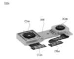
도면을 참조하면, 카메라 장치(100)는, 색상 카메라(CCm)와, IR 카메라(DCm)와, 색상 카메라(CCm)와 IR 카메라(DCm)를 연결하는 연결 부재(FLE), 색상 카메라(CCm)의 인터페이스(CTa)와 IR 카메라(DCm)의 인터페이스(CTb)를 구비하는 것을 예시한다.Referring to the drawing, the
한편, 색상 카메라(CCm)와 IR 카메라(DCm)를 연결하는 연결 부재(FLE)는, 플렉서블할 수 있다. 즉, 도 1a와 달리, 브라켓(BRK)이 구비되지 않을 수 있다. 이에 따라, 노 브라켓(braket)으로 인하여, 카메라 장치(100) 또는 카메라 장치(100)가 장착되는 전자 장치의 공간 설계의 자유도가 향상될 수 있다.Meanwhile, the connecting member (FLE) connecting the color camera (CCm) and the IR camera (DCm) may be flexible. That is, unlike FIG. 1A, the bracket BRK may not be provided. Accordingly, due to the absence of a bracket, the degree of freedom in spatial design of the
한편, 도 1b의 카메라 장치(100)에 따르면, 색상 카메라(CCm)와 IR 카메라(DCm) 사이의 간격 등이 불규칙적으로 가변될 수 있으며, 이러한 경우, 색상 이미지와 IR 이미지 사이의 캘리브레이션이 필요하게 된다. 색상 이미지와 IR 이미지 사이의 캘리브레이션에 대해서는, 도 6 이하를 참조하여 기술한다.Meanwhile, according to the
한편, 도 1b와 같은 본 발명의 실시예에 따른 카메라 장치(100)는, 다양한 전자 장치에 구비될 수 있다.Meanwhile, the
도 2는 전자 장치의 다양한 예를 설명하는 도면이다.Figure 2 is a diagram explaining various examples of electronic devices.
도 2를 참조하면, 도 1b와 같은 본 발명의 실시예에 따른 카메라 장치(100)는, 이동 단말기(200), 공기조화기(200a), 로봇청소기(200b), 냉장고(200c), 세탁기(200d), TV(200e), 차량, 드론 등의 다양한 전자 장치에 채용될 수 있다.Referring to FIG. 2, the
이하에서는, 이동 단말기(200)에, 카메라 장치(100)가 구비되는 것을 중심으로 기술한다.Hereinafter, the description will focus on the fact that the
도 3a는 도 1b의 색상 카메라와 IR 카메라의 내부 단면도이다.FIG. 3A is a cross-sectional view of the interior of the color camera and IR camera of FIG. 1B.
도면을 참조하면, 색상 카메라(CCm)는, 조리개(194a), 렌즈 장치(193a), 이미지 센서(Imsa)를 구비할 수 있다.Referring to the drawings, the color camera CCm may include an
조리개(194a)는, 렌즈 장치(193a)로 입사되는 광을 개폐할 수 있다.The
렌즈 장치(193a)는, 가변 초점을 위해 조정되는 복수의 렌즈를 구비할 수 있다.The
이미지 센서(Imsa)는, RGB 색상을 센싱하기 위해, RGb 필터(915a)와, 광 신호를 전기 신호로 변환하는 센서 어레이(911a)를 구비할 수 있다.The image sensor Imsa may include an
이에 따라, 이미지 센서(Imsa)는, 색상 이미지를 센싱하여, 출력할 수 있다.Accordingly, the image sensor Imsa can sense and output a color image.
IR 카메라(DCm)는, 조리개(194b), 렌즈 장치(193b), 이미지 센서(Imsb)를 구비할 수 있다.The IR camera (DCm) may include an aperture (194b), a lens device (193b), and an image sensor (Imsb).
조리개(194b)는, 렌즈 장치(193b)로 입사되는 광을 개폐할 수 있다.The
렌즈 장치(193b)는, 가변 초점을 위해 조정되는 복수의 렌즈를 구비할 수 있다.The
이미지 센서(Imsb)는, IR 이미지를 센싱하기 위해, IR 필터(915b)와, 광 신호를 전기 신호로 변환하는 센서 어레이(911b)를 구비할 수 있다.The image sensor Imsb may include an
이에 따라, 이미지 센서(Imsb)는, IR 이미지를 센싱하여, 출력할 수 있다.Accordingly, the image sensor Imsb can sense and output an IR image.
한편, 색상 카메라(CCm)는, 색상 이미지 외에 다양한 색상 이미지를 출력하는 것이 가능하다. 예를 들어, W색상 이미지 또는 RGBY 이미지 등을 출력할 수도 있다.Meanwhile, the color camera (CCm) is capable of outputting various color images in addition to color images. For example, a W color image or an RGBY image may be output.
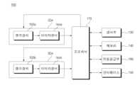
도 3b는 도 1b의 색상 카메라와 IR 카메라를 구비하는 카메라 장치의 내부 블록도이다.FIG. 3B is an internal block diagram of a camera device including the color camera and IR camera of FIG. 1B.
도면을 참조하면, 카메라 장치(100)는, 색상 카메라(CCm), IR 카메라(DCm), 프로세서(170), 센서부(130), 메모리(140), 전원공급부(190), 인터페이스(150)를 구비할 수 있다.Referring to the drawing, the
색상 카메라(CCm)는, 색상 이미지 출력을 위해, 렌즈 장치(193a), 이미지 센서(Imsa)를 구비할 수 있다.The color camera CCm may include a
색상 카메라(CCm) 내의 렌즈 장치(193a)는, 입사되는 입사광을 수신하며, 가변 초점을 위해 조정되는 복수의 렌즈를 구비할 수 있다.The
한편, 이미지 센서(Imsa)는, 전기 신호에 기초하여, 노출 시간이 조절될 수 있다.Meanwhile, the exposure time of the image sensor Imsa may be adjusted based on electrical signals.
IR 카메라(DCm)는, IR 이미지 출력을 위해, 렌즈 장치(193b), 이미지 센서(Imsb)를 구비할 수 있다.The IR camera (DCm) may be equipped with a lens device (193b) and an image sensor (Imsb) to output IR images.
IR 카메라(DCm) 내의 렌즈 장치(193b)는, 입사되는 입사광을 수신하며, 가변 초점을 위해 조정되는 복수의 렌즈를 구비할 수 있다.The
한편, 프로세서(170)는, 색상 카메라(CCm) 내의 이미지 센서(Imsa)로부터의 전기 신호에 기초한, 색상 이미지를 수신할 수 있다. 또는, 프로세서(170)는, 색상 카메라(CCm) 내의 이미지 센서(Imsa)로부터의 전기 신호에 기초하여 색상 이미지를 생성할 수 있다.Meanwhile, the
한편, 프로세서(170)는, IR 카메라(DCm) 내의 이미지 센서(Imsb)로부터의 전기 신호에 기초한, IR 이미지를 수신할 수 있다. 또는, 프로세서(170)는, IR 카메라(DCm) 내의 이미지 센서(Imsb)로부터의 전기 신호에 기초하여 IR 이미지를 생성할 수 있다.Meanwhile, the
한편, 프로세서(170)는, 색상 카메라(CCm)로부터의 색상 이미지와 IR 카메라(DCm)로부터의 IR 이미지의 차이에 기초하여 오차 정보를 연산하고, 연산된 오차 정보에 기초하여 색상 이미지와 IR 이미지 중 적어도 하나를 보상하여, 보상된 색상 이미지 또는 보상된 IR 이미지를 출력할 수 있다.Meanwhile, the
한편, 프로세서(170)는, 색상 카메라(CCm)로부터의 색상 이미지와 IR 카메라로부터의 IR 이미지의 각 특징점을 분석하여, 3차원 오차 정보를 연산하고, 연산된 3차원 오차 정보에 기초하여, 색상 이미지와 IR 이미지 중 적어도 하나를 보상하여, 보상된 색상 이미지 또는 보상된 IR 이미지를 출력할 수 있다.Meanwhile, the
한편, 프로세서(170)는, IR 이미지를 업 스케일링하고, 업 스케일링된 IR 이미지와 색상 이미지 사이의 3차원 오차 정보를 연산하고, 연산된 3차원 오차 정보에 기초하여, 색상 이미지와 IR 이미지 중 적어도 하나를 보상하여, 보상된 색상 이미지 또는 보상된 IR 이미지를 출력할 수 있다.Meanwhile, the
한편, 프로세서(170)는, 연산된 3차원 오차 정보에 기초하여, 보상되고 업스케일링된 IR 이미지를 색상 이미지에 매칭하여, 보상된 색상 이미지를 출력할 수 있다.Meanwhile, the
한편, 프로세서(170)는, 색상 이미지(Imgr)의 휘도 성분과, IR 이미지(Imgt)의 휘도 성분을 비교하여, 오차 정보를 연산하고, 연산된 오차 정보에 기초하여 색상 이미지와 IR 이미지 중 적어도 하나를 보상하여, 보상된 색상 이미지 또는 보상된 IR 이미지를 출력할 수 있다.Meanwhile, the
센서부(130)는, 카메라 장치(100)의 이동 정보 또는 위치 정보 등을 센싱할 수 있다. 이를 위해, 센서부(130)는, GPS 수신부, 또는 관성 센서(자이로 센서, 가속도 센서 등) 등을 구비할 수 있다.The
메모리(140)는, 카메라 장치(100)의 동작을 위한 데이터 또는 색상 카메라(CCm)로부터의 색상 이미지, IR 카메라(DCm)로부터의 IR 이미지 또는 보상된 색상 이미지 또는 IR 이미지를 저장할 수 있다.The
인터페이스(150)는, 카메라 장치(100) 내의 다른 유닛과의 데이터 전송을 위해 사용될 수 있다.The
전원공급부(190)는, 카메라 장치(100)의 동작을 위한 전원을 공급할 수 있다.The
예를 들어, 전원공급부(190)는, 외부로 입력되는 직류 전원 또는 교류 전원을 변환하여, 변환된 직류 전원을 프로세서(170), 색상 카메라(CCm), IR 카메라(DCm), 센서부(130), 메모리(140), 인터페이스(150) 등에 공급할 수 있다.For example, the
도 4a 내지 도 5c는 도 3b의 카메라 장치의 동작 설명에 참조되는 도면이다.FIGS. 4A to 5C are diagrams referenced in explaining the operation of the camera device of FIG. 3B.
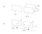
먼저, 도 4a의 (a)는, 색상 카메라(CCm)로부터의 색상 이미지(Lim)와, IR 카메라(DCm)로부터의 IR 이미지(Rim) 사이의 틀어짐으로 인하여, IR 이미지(Rim)를 캘리브레이션하는 것을 예시한다. 구체적으로, 도 4a의 (a)는, IR 이미지(Rim)를 보상한 IR 이미지(R'im)를 예시한다.First, (a) of FIG. 4A shows a method for calibrating the IR image (Rim) due to a discrepancy between the color image (Lim) from the color camera (CCm) and the IR image (Rim) from the IR camera (DCm). exemplifies this. Specifically, (a) of FIG. 4A illustrates an IR image (R'im) obtained by compensating the IR image (Rim).
보상한 IR 이미지(Rim)는, 3차원 변형(translation), 3차원 천이(shift), 또는 3차원 회전(rotation) 중 적어도 하나에 기초하여 보상된 것일 수 있다.The compensated IR image (Rim) may be compensated based on at least one of 3D translation, 3D shift, or 3D rotation.
여기서, 3차원 회전(rotation)은, 요(yaw), 피치(pitch), 롤(roll)을 포함하는 것일 수 있다.Here, three-dimensional rotation may include yaw, pitch, and roll.
다음, 도 4a의 (b)는, 색상 이미지(Lim)와, 보상된 IR 이미지(R'im)가 일정하게 정렬된 것을 예시한다. 이에 따라, 색상 이미지(Lim)와, 보상된 IR 이미지(R'im)를 매칭하여, 보상된 색상 이미지 또는 보상된 IR 이미지의 출력이 가능하게 된다.Next, (b) of FIG. 4A illustrates that the color image (Lim) and the compensated IR image (R'im) are consistently aligned. Accordingly, by matching the color image (Lim) and the compensated IR image (R'im), it is possible to output a compensated color image or a compensated IR image.
도 4b는, 색상 카메라(CCm)와 IR 카메라(DCm)를 이용하여 동일한 패턴(PAT)을 촬영하는 것을 예시한다.FIG. 4B illustrates photographing the same pattern (PAT) using a color camera (CCm) and an IR camera (DCm).
색상 카메라(CCm)의 3차원 회전(rotation), 3차원 변형(translation) 등에 의해, [R1,T1]과 같은, 틀어짐이 발생하며, 이에 따라, 색상 카메라(CCm)로부터 색상 이미지(Img1)가 획득된다.Due to the 3D rotation and 3D translation of the color camera (CCm), distortions such as [R1, T1] occur, and as a result, the color image (Img1) from the color camera (CCm) It is acquired.
다음, IR 카메라(DCm)의 3차원 회전(rotation), 3차원 변형(translation) 등에 의해, [R2,T2]과 같은, 틀어짐이 발생하며, 이에 따라, IR 카메라(DCm)로부터 IR 이미지(img2)가 획득된다.Next, due to the 3D rotation and 3D translation of the IR camera (DCm), distortion such as [R2, T2] occurs, and accordingly, the IR image (img2) from the IR camera (DCm) occurs. ) is obtained.
한편, 색상 이미지(Img1)와 IR 이미지(img2)의 차이는 왜곡 정도(H)로 나타날 수 있다.Meanwhile, the difference between the color image (Img1) and the IR image (img2) can be expressed as the degree of distortion (H).
한편, 프로세서(170)는, 색상 이미지(Img1)와 IR 이미지(img2)의 차이를 최소화하기 위해, 색상 이미지(Img1)와 IR 이미지(img2)의 차이인 왜곡 정도(H), 색상 이미지(Img1)의 회전, 변형 등의 틀어짐 정보([R1,T1]), IR 이미지(img2)의 회전, 변형 등의 틀어짐 정보([R2,T2])를 연산할 수 있다.Meanwhile, in order to minimize the difference between the color image (Img1) and the IR image (img2), the
그리고, 프로세서(170)는, 왜곡 정도(H), 색상 이미지(Img1)의 회전, 변형 등의 틀어짐 정보([R1,T1]), IR 이미지(img2)의 회전, 변형 등의 틀어짐 정보([R2,T2])에 기초하여, 오차를 저감하는 보상된 색상 이미지 또는 보상된 IR 이미지를 출력할 수 있다.And, the
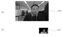
도 5a는 카메라 장치(100)의 색상 카메라(CCm)로부터의 색상 이미지(510)와 IR 카메라(DCm)로부터의 IR 이미지(515)를 예시한다.5A illustrates a
카메라 장치(100)의 색상 카메라(CCm)와 IR 카메라(DCm)의 해상도 차이가 있는 경우, 도면과 같이, 색상 이미지(510)의 해상도가 IR 이미지(515)의 해상도 보다 높게 나타날 수 있다.If there is a difference in resolution between the color camera (CCm) and the IR camera (DCm) of the
일단, 색상 이미지(510)와 IR 이미지(515)의 차이에 따른 캘리브레이션을 수행하기 위해, 색상 이미지(510)와 IR 이미지(515)의 해상도를 동일하게 조정하는 것이 필요하다.First, in order to perform calibration according to the difference between the
이를 위해, 프로세서(170)는, IR 이미지를 업 스케일링할 수 있다.To this end, the
또는, 프로세서(170)는, IR 이미지를 업 스케일링하고, 색상 이미지를 다운 스케일링할 수도 있다.Alternatively, the
도 5b는 다운 스케일링된 색상 이미지(520)와, 업 스케일링된 IR 이미지(525)를 예시한다.5B illustrates a downscaled
한편, 저해상도의 IR 이미지의 업 스케일링시, IR 이미지 내에 포함되는 패턴에 따라, 블러 등이 발생할 수 있다.Meanwhile, when upscaling a low-resolution IR image, blur, etc. may occur depending on the pattern included in the IR image.
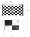
도 5c는, 흰색과 흑색의 사각 격자 패턴(PATm)의 일 영역(Arm)이 촬영된 IR 이미지(IArm)를 예시한다.FIG. 5C illustrates an IR image (IArm) in which one area (Arm) of the white and black square grid pattern (PATm) is captured.
IR 이미지(IArm)를 보면, 흑색과 흰색의 경계 영역(EGa,EGb)에 블러가 발생할 수 있으며, 이러한 현상은, IR 이미지를 업 스케일링할 경우, 더욱 두드러지게 된다.When looking at an IR image (IAm), blur may occur in the black and white boundary areas (EGa, EGb), and this phenomenon becomes more noticeable when the IR image is upscaled.
이에 따라, 색상 카메라(CCm)와 IR 카메라(DCm)의 캘리브레이션을 위해, 사용되는 패턴은, 사각 격자 패턴이 아닌, 도 7과 같은 원형의 격자 패턴이 바람직할 수 있다. 한편, 기준점 확정 등을 위해, 복수 사이즈의 원형의 격자 패턴이 바람직할 수 있다.Accordingly, for calibration of the color camera (CCm) and the IR camera (DCm), the pattern used may preferably be a circular grid pattern as shown in FIG. 7 rather than a square grid pattern. Meanwhile, for purposes such as determining a reference point, a circular grid pattern of multiple sizes may be desirable.
도 6은 카메라 장치의 동작 방법을 도시한 순서도이고, 도 7 내지 도 10f는 도 6의 동작 방법 설명에 참조되는 도면이다.FIG. 6 is a flowchart showing a method of operating a camera device, and FIGS. 7 to 10F are diagrams referred to in the description of the operating method of FIG. 6 .
먼저, 도 6을 참조하면, 카메라 장치(100) 내의 프로세서(170)는, 색상 카메라(CCm)로부터 색상 이미지를 획득한다(S610).First, referring to FIG. 6, the
다음, 카메라 장치(100) 내의 프로세서(170)는, IR 카메라(DCm)로부터 IR 이미지를 획득한다(S615).Next, the
획득되는 색상 이미지와 IR 이미지는, 동일한 패턴 또는 피사체에 대해 촬영된 이미지일 수 있다.The acquired color image and IR image may be images taken of the same pattern or subject.
예를 들어, 제1 시점에, 도 7과 같은 복수의 사이즈의 원형의 격자 패턴(PAT)을 촬영한 색상 이미지와 IR 이미지가 획득될 수 있다.For example, at a first time point, a color image and an IR image obtained by photographing a circular grid pattern (PAT) of a plurality of sizes as shown in FIG. 7 may be obtained.
도 7에서 도시된 복수의 사이즈의 원형의 격자 패턴(PAT)에 따르면, 그 중심에 제1 사이즈의 원형 패턴(Ba,Bb)이 배치되고, 제1 사이즈의 원형 패턴(Ba,Bb) 주위에 제2 사이즈의 원형 패턴(Bc,Bd)이 배치되는 것을 예시한다.According to the circular grid pattern (PAT) of a plurality of sizes shown in FIG. 7, circular patterns (Ba, Bb) of the first size are disposed at the center, and circular patterns (Ba, Bb) of the first size are arranged around the circular grid patterns (Ba, Bb) of the first size. This illustrates that circular patterns (Bc, Bd) of the second size are arranged.
이때, 원형 패턴은, 흑색 또는 컬러 색상일 수 있으며, 원형 패턴 주변의 배경은 백색일 수 있다.At this time, the circular pattern may be black or colored, and the background around the circular pattern may be white.
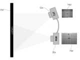
도 8a는 복수의 사이즈의 원형의 격자 패턴(PAT)을 촬영하는 색상 카메라(CCm)와 IR 카메라(DCm)의 상면도를 도시하며, 도 8b는 복수의 사이즈의 원형의 격자 패턴(PAT)을 촬영하는 색상 카메라(CCm)와 IR 카메라(DCm)의 측면도를 도시한다.FIG. 8A shows a top view of a color camera (CCm) and an IR camera (DCm) that capture circular grid patterns (PAT) of multiple sizes, and FIG. 8B shows a top view of a circular grid pattern (PAT) of multiple sizes. A side view of the color camera (CCm) and IR camera (DCm) taking pictures is shown.
도 8a 내지 도 8b를 참조하면, 일정 간격으로 이격되어 배치되는 색상 카메라(CCm)와 IR 카메라(DCm)는, 복수의 사이즈의 원형의 격자 패턴(PAT)에 대한, 색상 카메라(CCm)로부터의 색상 이미지(Imgr)와 IR 카메라(DCm)로부터의 IR 이미지(Imgt)가 획득될 수 있다.Referring to FIGS. 8A and 8B, the color camera (CCm) and the IR camera (DCm), which are arranged at regular intervals, capture the information from the color camera (CCm) for circular grid patterns (PAT) of a plurality of sizes. A color image (Imgr) and an IR image (Imgt) from an IR camera (DCm) can be acquired.
상술한 바와 같이, 색상 카메라(CCm)와 IR 카메라(DCm) 사이에 해상도 차이가 있는 경우, 프로세서(170)는, IR 이미지(Imgt)의 업 스케일링(up scaling) 등을 수행할 수 있다.As described above, when there is a resolution difference between the color camera (CCm) and the IR camera (DCm), the
다음, 카메라 장치(100) 내의 프로세서(170)는, 색상 이미지와 IR 이미지의 각 특징점을 분석하여, 3차원 오차 정보를 연산할 수 있다(S670).Next, the
다음, 카메라 장치(100) 내의 프로세서(170)는, 연산된 3차원 오차 정보에 기초하여, 보상된 색상 이미지 또는 보상된 IR 이미지를 출력할 수 있다(S680).Next, the
한편, 프로세서(170)는, 색상 카메라(CCm)로부터의 색상 이미지(Imgr)와 IR 카메라(DCm)로부터의 IR 이미지(Imgt)의 차이에 기초하여 오차 정보를 연산하고, 연산된 오차 정보에 기초하여 색상 이미지(Imgr)와 IR 이미지(Imgt) 중 적어도 하나를 보상하여, 보상된 색상 이미지 또는 보상된 IR 이미지를 출력할 수 있다. 이에 따라, 색상 카메라(CCm)로부터의 색상 이미지(Imgr)와 IR 카메라(DCm)로부터의 IR 이미지(Imgt)의 차이를 신속하고 정확하게 보상할 수 있게 된다.Meanwhile, the
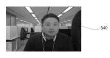
한편, 프로세서(170)는, 색상 카메라(CCm)로부터의 색상 이미지(Imgr)와 IR 카메라(DCm)로부터의 IR 이미지(Imgt)의 각 특징점을 분석하여, 3차원 오차 정보를 연산하고, 연산된 3차원 오차 정보에 기초하여, 색상 이미지(Imgr)와 IR 이미지(Imgt) 중 적어도 하나를 보상하여, 보상된 색상 이미지(540) 또는 보상된 IR 이미지(Imgt)를 출력할 수 있다. 특히, 3차원 오차 정보 연산에 기초하여, 색상 카메라(CCm)로부터의 색상 이미지(Imgr)와 IR 카메라(DCm)로부터의 IR 이미지(Imgt)의 차이를 신속하고 정확하게 보상할 수 있게 된다. Meanwhile, the
한편, 프로세서(170)는, IR 이미지(Imgt)를 업 스케일링하고, 업 스케일링된 IR 이미지(Imgt)와 색상 이미지(Imgr) 사이의 3차원 오차 정보를 연산하고, 연산된 3차원 오차 정보에 기초하여, 색상 이미지(Imgr)와 IR 이미지(Imgt) 중 적어도 하나를 보상하여, 보상된 색상 이미지 또는 보상된 IR 이미지를 출력할 수 있다. 이에 따라, 색상 카메라(CCm)로부터의 색상 이미지(Imgr)와 IR 카메라(DCm)로부터의 IR 이미지(Imgt)의 차이를 신속하고 정확하게 보상할 수 있게 된다.Meanwhile, the
한편, 3차원 오차 정보는, 색상 이미지(Imgr)와 IR 이미지(Imgt) 사이의 상대 회전 정보(Relative Rotation information)와, 상대 변형 정보(Relative Translation information) 또는 상대 천이 정보(Relative Shift information)를 포함할 수 있다. 이에 따라, 상대 회전 정보(Relative Rotation information)와, 상대 변형 정보(Relative Translation information) 또는 상대 천이 정보(Relative Shift information)에 기초하여, 색상 카메라(CCm)로부터의 색상 이미지(Imgr)와 IR 카메라(DCm)로부터의 IR 이미지(Imgt)의 차이를 신속하고 정확하게 보상할 수 있게 된다.Meanwhile, the 3D error information includes relative rotation information between the color image (Imgr) and the IR image (Imgt), and relative translation information or relative shift information. can do. Accordingly, based on relative rotation information, relative translation information, or relative shift information, a color image (Imgr) from a color camera (CCm) and an IR camera ( It is possible to quickly and accurately compensate for the difference in the IR image (Imgt) from DCm).
한편, 프로세서(170)는, 연산된 3차원 오차 정보에 기초하여, 보상되고 업스케일링된 IR 이미지(Imgt)를 색상 이미지(Imgr)에 매칭하여, 보상된 색상 이미지를 출력할 수 있다. 이에 따라, 색상 카메라(CCm)로부터의 색상 이미지(Imgr)와 IR 카메라(DCm)로부터의 IR 이미지(Imgt)의 차이를 신속하고 정확하게 보상할 수 있게 된다.Meanwhile, the
한편, 프로세서(170)는, 색상 이미지(Imgr)의 휘도 성분과, IR 이미지(Imgt)의 휘도 성분을 비교하여, 오차 정보를 연산하고, 연산된 오차 정보에 기초하여 색상 이미지(Imgr)와 IR 이미지(Imgt) 중 적어도 하나를 보상하여, 보상된 색상 이미지 또는 보상된 IR 이미지를 출력할 수 있다. 이에 따라, 색상 카메라(CCm)로부터의 색상 이미지(Imgr)와 IR 카메라(DCm)로부터의 IR 이미지(Imgt)의 차이를 신속하고 정확하게 보상할 수 있게 된다.Meanwhile, the
도 9는 프로세서(170) 내의 내부 블록도의 일예를 보여주는 도면이다.FIG. 9 is a diagram showing an example of an internal block diagram within the
도면을 참조하면, 프로세서(170)는, 색상 카메라(CCm)로부터의 색상 이미지(Imgr)와 IR 카메라(DCm)로부터의 IR 이미지(Imgt)의 각 특징점을 분석하는 특징점 분석부(910)와, 특징점 분석부(910)에서 분석된 각 특징점 정보에 기초하여, 외부 변수를 연산하는 외부 변수 연산부(920)와, 연산된 외부 변수에 기초하여, 3차원 오차 정보를 연산하는 오차 연산부(930)와, 3차원 오차 정보에 기초하여 오차를 수정하는 오차 수정부(940)를 포함할 수 있다. 이에 따라, 색상 카메라(CCm)로부터의 색상 이미지(Imgr)와 IR 카메라(DCm)로부터의 IR 이미지(Imgt)의 차이를 신속하고 정확하게 보상할 수 있게 된다.Referring to the drawing, the
도 10a는 특징점 분석부(910)에 입력되는 색상 카메라(CCm)로부터의 색상 이미지(Imgr)와 IR 카메라(DCm)로부터의 IR 이미지(Imgt)를 예시한다.FIG. 10A illustrates a color image (Imgr) from a color camera (CCm) and an IR image (Imgt) from an IR camera (DCm) input to the feature
한편, 특징점 분석부(910)는, 색상 카메라(CCm)로부터의 색상 이미지(Imgr)와 IR 카메라(DCm)로부터의 IR 이미지(Imgt)로부터 각각 패턴 또는 기준점을 검출하고, 검출된 패턴 또는 기준점에 기초하여 방향 벡터를 연산할 수 있다.Meanwhile, the feature
한편, 특징점 분석부(910)는, 색상 이미지(Imgr)와, IR 이미지(Imgt)로부터, 원 패턴을 검출하고, 원 패턴 중 기준점을 검출할 수 있다.Meanwhile, the feature
한편, 특징점 분석부(910)는, 검출된 원 패턴 또는 기준점에 기초하여, 방향 벡터를 연산할 수 있다.Meanwhile, the feature
그리고, 특징점 분석부(910)는, 검출된 원 패턴, 기준점 또는 방향 벡터에 기초하여, 특징점 분석을 수행할 수 있다. 즉, 특징점은, 원 패턴, 기준점 또는 방향 벡터를 포함하는 개념일 수 있다.Additionally, the feature
한편, 외부 변수 연산부(920)는, 특징점 분석부(910)에서 분석된 각 특징점 정보에 기초하여, 색상 이미지(Imgr)와 IR 이미지(Imgt) 각각의 회전 정보와, 변형 정보 또는 천이 정보를 연산할 수 있다.Meanwhile, the external
한편, 외부 변수 연산부(920)는, 색상 이미지(Imgr)와, IR 이미지(Imgt)의 호모그래피(Homography)를 연산할 수 있다.Meanwhile, the external
한편, 외부 변수 연산부(920)는, 연산된 호모그래피에 기초하여, 색상 이미지(Imgr)와 IR 이미지(Imgt) 각각의 회전 정보와, 변형 정보 또는 천이 정보를 연산할 수 있다.Meanwhile, the external
한편, 오차 연산부(930)는, 색상 이미지(Imgr)와 IR 이미지(Imgt) 각각의 회전 정보와, 변형 정보 또는 천이 정보에 기초하여, 색상 이미지(Imgr)와 IR 이미지(Imgt) 사이의 상대 회전 정보(Relative Rotation information)와, 상대 변형 정보(Relative Translation information) 또는 상대 천이 정보(Relative Shift information)를 연산할 수 있다.Meanwhile, the
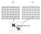
한편, 오차 연산부(930)는, 색상 이미지(Imgr)와 IR 이미지(Imgt)에 기초하여 재투영 오차(reprojection error)를 연산할 수 있다.Meanwhile, the
도 10b는 색상 이미지(Imgr)와 보상된 IR 이미지(I'mgt)에 기초하여 재투영 오차를 연산하는 것을 예시한다.Figure 10b illustrates calculating the reprojection error based on the color image (Imgr) and the compensated IR image (I'mgt).
재투영 오차 정보는, 상술한 상대 회전 정보(Relative Rotation information)와, 상대 변형 정보(Relative Translation information) 또는 상대 천이 정보(Relative Shift information)를 포함할 수 있다.The reprojection error information may include the above-described relative rotation information, relative translation information, or relative shift information.
한편, 오차 수정부(940)는, 연산된 3차원 오차 정보에 기초하여, 보상되고 업스케일링된 IR 이미지(Imgt)를 색상 이미지(Imgr)에 매칭하여, 보상된 색상 이미지를 출력할 수 있다. 이에 따라, 색상 카메라(CCm)로부터의 색상 이미지(Imgr)와 IR 카메라(DCm)로부터의 IR 이미지(Imgt)의 차이를 신속하고 정확하게 보상할 수 있게 된다.Meanwhile, the
한편, 오차 수정부(940)는, 연산된 3차원 오차 정보에 기초하여, 보상된 색상 이미지 또는 보상된 IR 이미지를 출력할 수 있다.Meanwhile, the
도 10c는 보상된 IR 이미지(Imgev)를 예시한다.Figure 10C illustrates a compensated IR image (Imgev).
이에 따라, 색상 카메라(CCm)로부터의 색상 이미지(Imgr)와 IR 카메라(DCm)로부터의 IR 이미지(Imgt)의 차이를 신속하고 정확하게 보상할 수 있게 된다.Accordingly, it is possible to quickly and accurately compensate for the difference between the color image (Imgr) from the color camera (CCm) and the IR image (Imgt) from the IR camera (DCm).
도 10d는 다른 색상 이미지와 다른 IR 이미지를 예시한다.Figure 10d illustrates another color image and another IR image.
도면을 참조하면, 프로세서(170)는, 카메라 장치(100)의 색상 카메라(CCm)로부터의 색상 이미지(510)와 IR 카메라(DCm)로부터의 IR 이미지(515)를 수신할 수 있다.Referring to the drawing, the
카메라 장치(100)의 색상 카메라(CCm)와 IR 카메라(DCm)의 해상도 차이가 있는 경우, 도면과 같이, 색상 이미지(510)의 해상도가 IR 이미지(515)의 해상도 보다 높게 나타날 수 있다.If there is a difference in resolution between the color camera (CCm) and the IR camera (DCm) of the
이에 따라, 프로세서(170)는, 색상 이미지(510)를 다운 스케일링하고, IR 이미지(515)를 업 스케일링할 수 있다.Accordingly, the
도 10e는 다운 스케일링된 색상 이미지(520)와 업 스케일링된 IR 이미지(525)를 예시한다.Figure 10E illustrates a down-scaled
한편, 프로세서(170)는, 다운 스케일링된 색상 이미지(520)와 업 스케일링된 IR 이미지(525)를 이용하여, 매칭을 수행할 수 있다.Meanwhile, the
예를 들어, 프로세서(170)는, 다운 스케일링된 색상 이미지(520)에 업 스케일링된 IR 이미지(525)를 매칭시킬 수 있다. 그리고, 프로세서(170)는, 그 차이에 기초하여, 오차 정보를 연산할 수 있다.For example, the
예를 들어, 프로세서(170)는, 다운 스케일링된 색상 이미지(520)에 업 스케일링된 IR 이미지(525)에 기초하여, 각 특징점을 분석하여, 3차원 오차 정보를 연산할 수 있다.For example, the
구체적으로, 프로세서(170)는, 다운 스케일링된 색상 이미지(520)에 업 스케일링된 IR 이미지(525)에 기초하여, 각 특징점을 분석하여, 색상 이미지(Imgr)와 IR 이미지(Imgt) 사이의 상대 회전 정보(Relative Rotation information)와, 상대 변형 정보(Relative Translation information) 또는 상대 천이 정보(Relative Shift information) 등의 3차원 오차 정보를 연산할 수 있다.Specifically, the
그리고, 프로세서(170)는, 연산된 3차원 오차 정보에 기초하여, 보상된 색상 이미지 또는 보상된 IR 이미지를 출력할 수 있다.Additionally, the
도 10f는 보상된 색상 이미지(540)를 예시한다. 도면과 달리, 보상된 IR 이미지가 출력되는 것도 가능하다.Figure 10F illustrates compensated
이에 따라, 색상 카메라로부터의 색상 이미지와 IR 카메라로부터의 IR 이미지의 차이를 신속하고 정확하게 보상할 수 있게 된다.Accordingly, it is possible to quickly and accurately compensate for the difference between the color image from the color camera and the IR image from the IR camera.
한편, 색상 카메라로부터 획득한 색상 이미지와, IR 카메라로부터 획득한 IR 이미지를 조합하여, 다양한 효과를 구현하는 것이 가능하다.Meanwhile, it is possible to implement various effects by combining color images obtained from a color camera and IR images obtained from an IR camera.
본 발명에서는, 색상 카메라로부터 획득한 색상 이미지와, IR 카메라로부터 획득한 IR 이미지를 조합하여, 보케(bokeh) 이미지를 생성하는 방안을 제시한다. 구체적으로, 전경이 선명하고, 배경이 흐릿한 보케(bokeh) 이미지를 생성하는 방안을 제시한다. 이에 대해서는 도 11 이하를 참조하여 기술한다.The present invention proposes a method of generating a bokeh image by combining a color image obtained from a color camera and an IR image obtained from an IR camera. Specifically, we propose a method for generating a bokeh image with a clear foreground and a blurry background. This will be described with reference to FIG. 11 and below.
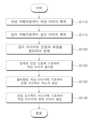
도 11은 본 발명의 실시예에 따른 카메라 장치의 동작 방법을 도시한 순서도이고, 도 12 내지 도 16c는 도 11의 동작 방법 설명에 참조되는 도면이다.FIG. 11 is a flowchart showing a method of operating a camera device according to an embodiment of the present invention, and FIGS. 12 to 16C are diagrams referenced in the description of the operating method of FIG. 11 .
도면을 참조하면,카메라 장치(100) 내의 프로세서(170)는, 색상 카메라(CCm)로부터 색상 이미지를 획득한다(S1110).Referring to the drawing, the
다음, 카메라 장치(100) 내의 프로세서(170)는, IR 카메라(DCm)로부터 IR 이미지를 획득한다(S1115).Next, the
획득되는 색상 이미지와 IR 이미지는, 동일한 패턴 또는 피사체에 대해 촬영된 이미지일 수 있다.The acquired color image and IR image may be images taken of the same pattern or subject.
예를 들어, 제1 시점에, 도 7과 같은 복수의 사이즈의 원형의 격자 패턴(PAT)을 촬영한 색상 이미지와 IR 이미지가 획득될 수 있다.For example, at a first time point, a color image and an IR image obtained by photographing a circular grid pattern (PAT) of a plurality of sizes as shown in FIG. 7 may be obtained.
다른 예로, 도 10d와 같이, 공통의 얼굴 영역을 포함하는 색상 이미지와 IR 이미지가 획득될 수 있다.As another example, as shown in FIG. 10D, a color image and an IR image including a common facial area may be obtained.
다음, 카메라 장치(100) 내의 프로세서(170)는, IR 카메라(DCm)로부터의 IR 이미지로부터 전경 영역과 배경 영역을 분리하고 정제할 수 있다(S1120).Next, the
다음, 카메라 장치(100) 내의 프로세서(170)는, 정제된 전경 신호에 기초하여 색상 이미지를 필터링할 수 있다(S1125).Next, the
다음, 카메라 장치(100) 내의 프로세서(170)는, 필터링된 색상 이미지에 기초하여 전경 오브젝트 마스크를 생성할 수 있다(S1130).Next, the
다음, 카메라 장치(100) 내의 프로세서(170)는, 전경 오브젝트 마스크에 기초하여, 색상 이미지의 보케 이미지를 생성할 수 있다(S1130).Next, the
한편, 전경 영역은 얼굴 영역을 포함할 수 있으며, 보케 이미지는, 얼굴 영역이, 배경 영역 보다 선명할 수 있다. 즉, 배경 영역이 흐릿해지며, 얼굴 영역은 보다 선명해질 수 있다.Meanwhile, the foreground area may include a face area, and in the bokeh image, the face area may be clearer than the background area. That is, the background area becomes blurred and the face area becomes clearer.
이에 따라, IR 카메라(DCm)로부터의 IR 이미지를 이용하여 색상 카메라(CCm)로부터의 색상 이미지에 대한 보케 이미지를 간단하게 생성할 수 있게 된다.Accordingly, it is possible to simply generate a bokeh image for the color image from the color camera (CCm) using the IR image from the IR camera (DCm).
한편, 프로세서(170)는, IR 카메라(DCm)로부터의 IR 이미지로부터 전경 영역과 배경 영역을 분리하고, 분리된 전경 영역에 기초하여, 색상 카메라(CCm)로부터의 색상 이미지를 필터링하여, 색상 이미지의 보케 이미지를 생성할 수 있다. 이에 따라, IR 카메라(DCm)로부터의 IR 이미지를 이용하여 색상 카메라(CCm)로부터의 색상 이미지에 대한 보케 이미지를 간단하게 생성할 수 있게 된다.Meanwhile, the
한편, 프로세서(170)는, 필터링된 색상 이미지에 기초하여 전경 오브젝트 마스크를 생성하고, 전경 오브젝트 마스크에 기초하여 색상 이미지의 보케 이미지를 생성할 수 있다. 이에 따라, IR 카메라(DCm)로부터의 IR 이미지를 이용하여 색상 카메라(CCm)로부터의 색상 이미지에 대한 보케 이미지를 간단하게 생성할 수 있게 된다.Meanwhile, the
한편, 프로세서(170)는, 색상 카메라(CCm)로부터의 색상 이미지를 다운 스케일링하고, IR 이미지로부터 분리된 전경 영역에 기초하여, 다운 스케일링된 색상 이미지를 필터링할 수 있다. 이에 따라, IR 카메라(DCm)로부터의 IR 이미지를 이용하여 색상 카메라(CCm)로부터의 색상 이미지에 대한 보케 이미지를 간단하게 생성할 수 있게 된다.Meanwhile, the
한편, 프로세서(170)는, 색상 카메라(CCm)로부터의 색상 이미지를 다운 스케일링하고, 필터링된 다운 스케일링 색상 이미지를 업 스케일링하고, 업 스케일링된 색상 이미지에 기초하여, 다운 스케일링된 색상 이미지를 필터링할 수 있다. 이에 따라, IR 카메라(DCm)로부터의 IR 이미지를 이용하여 색상 카메라(CCm)로부터의 색상 이미지에 대한 보케 이미지를 간단하게 생성할 수 있게 된다.Meanwhile, the
한편, 프로세서(170)는, 필터링된 다운 스케일링된 색상 이미지에 기초하여, 전경 오브젝트 마스크를 생성할 수 있다. 이에 따라, IR 카메라(DCm)로부터의 IR 이미지를 이용하여 색상 카메라(CCm)로부터의 색상 이미지에 대한 보케 이미지를 간단하게 생성할 수 있게 된다.Meanwhile, the
한편, 프로세서(170)는, 색상 카메라(CCm)로부터의 색상 이미지를 다운 스케일링하고, 전경 오브젝트 마스크에 기초하여, 다운 스케일링된 색상 이미지를 필터링하며, 필터링된 색상 이미지와, 전경 오브젝트 마스크를 업 스케일링하고, 업 스케일링된 색상 이미지와 업 스케일링된 전력 오브젝트 마스크를 합성하여, 보케 이미지를 생성할 수 있다. 이에 따라, IR 카메라(DCm)로부터의 IR 이미지를 이용하여 색상 카메라(CCm)로부터의 색상 이미지에 대한 보케 이미지를 간단하게 생성할 수 있게 된다.Meanwhile, the
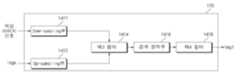
도 12는 IR 이미지로부터 전경과 배경을 분리하여 신호 처리를 수행하는 것을 보여주는 도면이다.Figure 12 is a diagram showing signal processing performed by separating the foreground and background from an IR image.
도면을 참조하면, 프로세서(170)는, IR 카메라(DCm)로부터의 IR 이미지로부터 전경 영역과 배경 영역을 분리하는 전경 배경 분리부(1210)와, 전경 영역을 필터링하는 전경 필터(1213)와, 필터링된 전경 영역을 정제(refine)하는 전경 정제부(1223)와, 배경 영역을 필터링하는 배경 필터(1216)와, 필터링된 배경 영역을 정제하는 배경 정제부(1226)를 포함할 수 있다.Referring to the drawing, the
이에 따라, 프로세서(170)는, IR 카메라(DCm)로부터의 IR 이미지로부터, 분리되어 정제된 전경 영역과, 배경 영역을 출력할 수 있다.Accordingly, the
한편, 전경 필터(1213)와 배경 필터(1216)는, 분리된 전경 영역과 배경 영역의 잡음 신호 제거를 위한 배경 신호의 잡음 신호 제거를 위한 메디안 필터링을 수행할 수 있다.Meanwhile, the
한편, 전경 정제부(1223)와, 배경 정제부(1226)는, 분리된 전경 영역과 배경 영역의 홀(hole) 영역 채움 처리를 통한 경계 신호 정제를 수행할 수 있다.Meanwhile, the
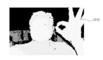
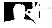
도 13a는 도 12의 전경 배경 분리부(1210)에 입력되는 IR 이미지(1310)를 예시한다.FIG. 13A illustrates an
도 13b는 전경 배경 분리부(1210)에서 분리된 전경 영역(1315)을 예시한다.13B illustrates
도 13c는 전경 필터(1213)에서 필터링된 전경 영역(1320)을 예시한다.Figure 13C illustrates the
도 13d는 전경 정제부(1223)에서 경계 영역 정제된 전경 영역(1325)을 예시한다.FIG. 13D illustrates a
도 13a 내지 도 13d를 참조하면, 전경 배경 분리부(1210), 전경 필터(1213), 전경 정제부(1223) 등의 동작에 따라, 잡음이 제거된 전경 영역(1325)이 추출되게 된다.Referring to FIGS. 13A to 13D , the
도 14a 내지 도 14c는 전경 오브젝트 마스크의 생성을 위해 참조되는 도면이다.14A to 14C are diagrams referenced for creating a foreground object mask.
먼저, 도 14a를 참조하면, 프로세서(170)는, 색상 카메라(CCm)로부터의 색상 이미지를 다운 스케일링하는 다운 스케일링부(1402)와, IR 이미지로부터 분리된 전경 영역에 기초하여, 다운 스케일링된 색상 이미지를 필터링하는 제1 필터(1404)와, 제1 필터(1404)로부터의 색상 이미지의 경계 신호를 정제하는 경계 정제부(1406)와, 경계 정제부(1406)로부터의 신호를 필터링하는 제2 필터(1406)를 포함할 수 있다.First, referring to FIG. 14A, the
다운 스케일링부(1402)는, IR 이미지와의 해상도 차이를 보상하기 위해, 색상 카메라(CCm)로부터의 색상 이미지를 다운 스케일링할 수 있다.The
다음, 제1 필터(1404)는, 도 12의 전경 정제부(1223)로부터의 전경 영역과, 다운 스케일링부(1402)로부터의 다운 스케일링된 색상 이미지에 기초하여, 가이드 필터링(guided filtering)을 수행할 수 있다.Next, the
그리고, 경계 정제부(1406)는, 제1 필터(1404)로부터의 색상 이미지의 경계 신호를 정제하고, 제2 필터(1406)는, 경계 정제부(1406)로부터의 신호를 필터링할 수 있다.Additionally, the
이때, 제2 필터(1406)는, 불필요한 잡음 신호 제거를 위한 메디안 필터링을 수행하고, 필터링된 신호(Imgk)를 출력할 수 있다. 이때, 필터링된 신호(Imgk)는, 전경 영역에 대응할 수 있다.At this time, the
다음, 도 14b를 참조하면, 프로세서(170)는, 색상 카메라(CCm)로부터의 색상 이미지를 다운 스케일링하는 제2 다운 스케일링부(1411)와, 제2 필터(1406)로부터의 신호(Imgk)를 업 스케일링하는 업 스케일링부(1412)와, 업 스케일링부(1412)로부터의 신호에 기초하여, 제2 다운 스케일링된 색상 이미지를 필터링하는 제3 필터(1414)와, 제3 필터(1414)로부터의 색상 이미지의 경계 신호를 정제하는 제2 경계 정제부(1416)와, 제2 경계 정제부(1416)로부터의 신호를 필터링하는 제4 필터(1418)를 더 포함할 수 있다.Next, referring to FIG. 14B, the
제2 다운 스케일링부(1411)는, IR 이미지와의 해상도 차이를 보상하기 위해, 색상 카메라(CCm)로부터의 색상 이미지를 다운 스케일링할 수 있다.The
업 스케일링부(1412)는, 제2 필터(1406)로부터의 신호(Imgk)를 업 스케일링할 수 있다. 특히, 색상 이미지와의 비교를 위해, 전경 영역을 업 스케일링할 수 있다.The
다음, 제3 필터(1414)는, 업 스케일링부(1412)로부터의 전경 영역과, 제2 다운 스케일링부(1411)로부터의 다운 스케일링된 색상 이미지에 기초하여, 가이드 필터링(guided filtering)을 수행할 수 있다.Next, the
그리고, 제2 경계 정제부(1416)는, 제3 필터(1414)로부터의 색상 이미지의 경계 신호를 정제하고, 제4 필터(1418)는, 제2 경계 정제부(1416)로부터의 신호를 필터링할 수 있다.Then, the
이때, 제4 필터(1418)는, 제3 필터(1414)와 달리, 불필요한 잡음 신호 제거를 위한 메디안 필터링을 수행하고, 필터링된 신호(Imgl)를 출력할 수 있다. 이때, 필터링된 신호(Imgl)는, 전경 영역에 대응할 수 있다.At this time, the
다음, 도 14c를 참조하면, 프로세서(170)는, 제4 필터(1418)로부터의 다운 스케일링된 색상 이미지를 업 스케일링하는 제2 업 스케일링부(1422)와, 제2 업 스케일링부(1422)로부터의 신호를 필터링하여 전경 오브젝트 마스크를 출력하는 제5 필터(1428)를 더 포함할 수 있다Next, referring to FIG. 14C, the
제2 업 스케일링부(1422)는, 제4 필터(1418)로부터의 신호(Imgl)를 업 스케일링할 수 있다.The second up-
다음, 제5 필터(1428)는, 제2 업 스케일링부(1422)로부터의 전경 영역에 대한 가우시안 필터링(Gaussian filtering)을 수행할 수 있다. 이에 따라, 제5 필터(1428)는, 전경 오브젝트 마스크를 생성하여 출력할 수 있다.Next, the
도 15a는 색상 카메라(CCm)로부터의 색상 이미지(1510)를 예시한다.15A illustrates a
다음, 도 15b는 도 12의 전경 정제부(1223)에서 경계 영역 정제된 전경 영역(1515)을 예시한다. 도 15b에 따르면, 도 12의 전경 배경 분리부(1210), 전경 필터(1213), 전경 정제부(1223) 등의 동작에 따라, 잡음이 제거된 전경 영역(1515)이 추출되게 된다.Next, FIG. 15B illustrates the
한편, 보다 깨끗한 전경 영역 처리 및 전경 오브젝트 마스크 생성을 위해, 도 14a 내지 도 14c에서 설명한 신호 처리가 필요하다.Meanwhile, for clearer foreground area processing and foreground object mask generation, the signal processing described in FIGS. 14A to 14C is necessary.
도 15c는 도 14a의 제2 필터(1408)에서 필터링된 전경 영역(1520)을 예시한다.FIG. 15C illustrates the filtered
다음, 도 15d는 도 14b의 제4 필터(1418)에서 필터링된 전경 영역(1525)을 예시한다.Next, Figure 15D illustrates the
다음, 도 15e는 도 14c의 제5 필터(1428)에서 필터링된 전경 영역(1530)을 예시한다.Next, Figure 15E illustrates the
도 15c에 비해 도 15d의 전경 영역(1525)이 보다 깨끗하고 선명하며, 도 15d 보다 도 15e의 전경 영역(1530)이 보다 깨끗하고 선명한 것을 알 수 있다.It can be seen that the
이에 따라, 도 15e와 같이, 선명한 전경 오브젝트 마스크(1530)를 생성하여 출력할 수 있게 된다.Accordingly, as shown in FIG. 15e, a clear
한편, 도 16a를 참조하면, 프로세서(170)는, 색상 카메라(CCm)로부터의 색상 이미지를 다운 스케일링하는 제3 다운 스케일링부(1432)와, 전경 오브젝트 마스크에 기초하여, 제3 다운 스케일링부(1432)로부터의 색상 이미지를 필터링하는 제6 필터(1434)와, 제6 필터(1434)로부터의 색상 이미지를 업 스케일링하는 제3 업 스케일링부(1435)와, 전경 오브젝트 마스크를 업 스케일링하는 제4 업 스케일링부(1437)와, 제3 업 스케일링부(1435)와 제4 업 스케일링부(1437)로부터의 신호를 합성하여, 보케 이미지를 출력하는 합성부(1439)를 포함할 수 있다. 이에 따라, IR 카메라(DCm)로부터의 IR 이미지를 이용하여 색상 카메라(CCm)로부터의 색상 이미지에 대한 보케 이미지를 간단하게 생성할 수 있게 된다.Meanwhile, referring to FIG. 16A, the
제3 다운 스케일링부(1432)는, IR 이미지와의 해상도 차이를 보상하기 위해, 색상 카메라(CCm)로부터의 색상 이미지를 다운 스케일링할 수 있다.The
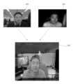
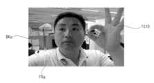
도 16b는 색상 카메라(CCm)로부터의 색상 이미지(1510)를 예시한다. 특히, 도 16b는 얼굴 영역을 포함하는 전경 영역(Fra)과 배경 영역(Bka)을 포함하는 색상 이미지(1510)를 예시한다.16B illustrates a
제6 필터(1434)는, 제3 다운 스케일링부(1432)로부터의 색상 이미지와 전경 오브젝트 마스크에 기초하여, 제3 다운 스케일링부(1432)로부터의 색상 이미지에 대해 적응적 바이레터럴 필터링을 수행할 수 있다.The
이에 따라, 제6 필터(1434)는, 전경 오브젝트 마스크 이외의 영역에 보케 효과를 적용할 수 있다. 즉, 전경 영역은 선명하고, 배경 영역은 흐릿한 색상 이미지를 출력할 수 있다.Accordingly, the
다음, 제3 업 스케일링부(1435)는, 제6 필터(1434)로부터의 색상 이미지를 업 스케일링하고, 제4 업 스케일링부(1437)는, 전경 오브젝트 마스크를 업 스케일링할 수 있다.Next, the third up-
그리고, 합성부(1439)는, 제3 업 스케일링부(1435)와 제4 업 스케일링부(1437)로부터의 신호를 합성하여, 도 16c와 같은 보케 이미지(1550)를 출력할 수 있다. 이에 따라, 얼굴 영역을 포함하는 전경 영역(Frb)은 선명하고, 배경 영역(Bkb)은 흐릿한 색상 이미지를 출력할 수 있다.Additionally, the
이에 따라, 배경 영역이 아웃 포커싱되며, 전경 영역이 포커싱된 보케 이미지(1550)를 간단하고 정확하게 생성할 수 있게 된다.Accordingly, the background area is out of focus, and a
또한, 이상에서는 본 발명의 바람직한 실시예에 대하여 도시하고 설명하였지만, 본 발명은 상술한 특정의 실시예에 한정되지 아니하며, 청구범위에서 청구하는 본 발명의 요지를 벗어남이 없이 당해 발명이 속하는 기술분야에서 통상의 지식을 가진자에 의해 다양한 변형실시가 가능한 것은 물론이고, 이러한 변형실시들은 본 발명의 기술적 사상이나 전망으로부터 개별적으로 이해되어져서는 안될 것이다.In addition, although preferred embodiments of the present invention have been shown and described above, the present invention is not limited to the specific embodiments described above, and the technical field to which the invention pertains without departing from the gist of the present invention as claimed in the claims. Of course, various modifications can be made by those of ordinary skill in the art, and these modifications should not be understood individually from the technical idea or perspective of the present invention.
Claims (15)
Translated fromKorean깊이 카메라;
상기 깊이 카메라로부터의 깊이 이미지로부터 전경 영역과 배경 영역을 분리하고, 상기 분리된 전경 영역 또는 배경 영역에 기초하여 상기 색상 카메라로부터의 색상 이미지를 필터링하여, 상기 색상 이미지의 보케 이미지를 생성하는 프로세서;를 포함하며,
상기 프로세서는,
상기 색상 카메라로부터의 색상 이미지를 다운 스케일링하고, 상기 깊이 이미지로부터 분리된 상기 전경 영역에 기초하여, 상기 다운 스케일링된 색상 이미지를 필터링하는 것을 특징으로 하는 카메라 장치.color camera;
depth camera;
a processor for separating a foreground and background area from a depth image from the depth camera and filtering a color image from the color camera based on the separated foreground or background areas to generate a bokeh image of the color image; Includes,
The processor,
A camera device, characterized in that downscaling a color image from the color camera and filtering the downscaled color image based on the foreground region separated from the depth image.
상기 프로세서는,
상기 깊이 카메라로부터의 깊이 이미지로부터 전경 영역과 배경 영역을 분리하고, 상기 분리된 전경 영역에 기초하여, 상기 색상 카메라로부터의 색상 이미지를 필터링하여, 상기 색상 이미지의 상기 보케 이미지를 생성하는 것을 특징으로 하는 카메라 장치.According to paragraph 1,
The processor,
separating a foreground and background region from a depth image from the depth camera, and filtering a color image from the color camera based on the separated foreground region to generate the bokeh image of the color image. camera device.
상기 프로세서는,
상기 필터링된 색상 이미지에 기초하여 전경 오브젝트 마스크를 생성하고, 상기 전경 오브젝트 마스크에 기초하여 상기 색상 이미지의 상기 보케 이미지를 생성하는 것을 특징으로 하는 카메라 장치.According to paragraph 1,
The processor,
A camera device characterized in that: generating a foreground object mask based on the filtered color image, and generating the bokeh image of the color image based on the foreground object mask.
상기 프로세서는,
상기 색상 카메라로부터의 색상 이미지를 다운 스케일링하고, 상기 필터링된 다운 스케일링 색상 이미지를 업 스케일링하고, 업 스케일링된 색상 이미지에 기초하여, 상기 다운 스케일링된 색상 이미지를 필터링하는 것을 특징으로 하는 카메라 장치.According to paragraph 1,
The processor,
Downscaling a color image from the color camera, upscaling the filtered downscaled color image, and filtering the downscaled color image based on the upscaled color image.
상기 프로세서는,
상기 필터링된 다운 스케일링된 색상 이미지에 기초하여, 전경 오브젝트 마스크를 생성하는 것을 특징으로 하는 카메라 장치.According to clause 5,
The processor,
A camera device, characterized in that for generating a foreground object mask based on the filtered down-scaled color image.
상기 프로세서는,
상기 색상 카메라로부터의 색상 이미지를 다운 스케일링하고, 상기 전경 오브젝트 마스크에 기초하여, 상기 다운 스케일링된 색상 이미지를 필터링하며, 상기 필터링된 색상 이미지와, 상기 전경 오브젝트 마스크를 업 스케일링하고, 상기 업 스케일링된 색상 이미지와 상기 업 스케일링된 전경 오브젝트 마스크를 합성하여, 상기 보케 이미지를 생성하는 것을 특징으로 하는 카메라 장치.According to paragraph 3,
The processor,
Downscale a color image from the color camera, filter the downscaled color image based on the foreground object mask, upscale the filtered color image and the foreground object mask, and based on the foreground object mask, upscale the upscaled color image. A camera device characterized in that the bokeh image is generated by combining a color image and the up-scaled foreground object mask.
상기 전경 영역은 얼굴 영역을 포함하며,
상기 보케 이미지는, 상기 얼굴 영역이, 상기 배경 영역 보다 선명한 것을 특징으로 하는 카메라 장치.According to paragraph 1,
The foreground area includes a face area,
The bokeh image is a camera device wherein the face area is clearer than the background area.
상기 프로세서는,
상기 깊이 카메라로부터의 상기 깊이 이미지로부터 전경 영역과 배경 영역을 분리하는 전경 배경 분리부;
상기 전경 영역을 필터링하는 전경 필터;
상기 필터링된 전경 영역을 정제하는 전경 정제부;
상기 배경 영역을 필터링하는 배경 필터;
상기 필터링된 배경 영역을 정제하는 배경 정제부;를 포함하는 것을 특징으로 하는 카메라 장치.According to paragraph 1,
The processor,
a foreground and background separation unit that separates a foreground area and a background area from the depth image from the depth camera;
a foreground filter that filters the foreground area;
a foreground refinement unit that refines the filtered foreground area;
a background filter that filters the background area;
A camera device comprising a background purification unit that refines the filtered background area.
상기 프로세서는.
상기 색상 카메라로부터의 상기 색상 이미지를 다운 스케일링하는 다운 스케일링부;
상기 깊이 이미지로부터 분리된 상기 전경 영역에 기초하여, 상기 다운 스케일링된 색상 이미지를 필터링하는 제1 필터;
상기 제1 필터로부터의 상기 색상 이미지의 경계 신호를 정제하는 경계 정제부;
상기 경계 정제부로부터의 신호를 필터링하는 제2 필터;를 포함하는 것을 특징으로 하는 카메라 장치.According to paragraph 1,
The processor is.
a downscaling unit that downscales the color image from the color camera;
a first filter for filtering the downscaled color image based on the foreground region separated from the depth image;
a boundary purification unit that refines a boundary signal of the color image from the first filter;
A camera device comprising a second filter that filters the signal from the boundary refinement unit.
상기 프로세서는,
상기 색상 카메라로부터의 색상 이미지를 다운 스케일링하는 제2 다운 스케일링부;
상기 제2 필터로부터의 신호를 업 스케일링하는 업 스케일링부;
상기 업 스케일링부로부터의 신호에 기초하여, 상기 제2 다운 스케일링된 색상 이미지를 필터링하는 제3 필터;
상기 제3 필터로부터의 상기 색상 이미지의 경계 신호를 정제하는 제2 경계 정제부;
상기 제2 경계 정제부로부터의 신호를 필터링하는 제4 필터;를 더 포함하는 것을 특징으로 하는 카메라 장치.According to clause 10,
The processor,
a second downscaling unit that downscales the color image from the color camera;
an upscaling unit that upscales the signal from the second filter;
a third filter for filtering the second down-scaled color image based on the signal from the up-scaling unit;
a second boundary purification unit that refines a boundary signal of the color image from the third filter;
The camera device further includes a fourth filter that filters the signal from the second boundary purification unit.
상기 프로세서는,
상기 제4 필터로부터의 다운 스케일링된 색상 이미지를 업 스케일링하는 제2 업 스케일링부;
상기 제2 업 스케일링부로부터의 신호를 필터링하여 전경 오브젝트 마스크를 출력하는 제5 필터;를 더 포함하는 것을 특징으로 하는 카메라 장치.According to clause 11,
The processor,
a second up-scaling unit that up-scales the down-scaled color image from the fourth filter;
A fifth filter that filters the signal from the second upscaling unit and outputs a foreground object mask.
상기 프로세서는,
상기 색상 카메라로부터의 색상 이미지를 다운 스케일링하는 제3 다운 스케일링부;
상기 전경 오브젝트 마스크에 기초하여, 상기 제3 다운 스케일링부로부터의 색상 이미지를 필터링하는 제6 필터;
상기 제6 필터로부터의 색상 이미지를 업 스케일링하는 제3 업 스케일링부;
상기 전경 오브젝트 마스크를 업 스케일링하는 제4 업 스케일링부;
상기 제3 업 스케일링부와 상기 제4 업 스케일링부로부터의 신호를 합성하여, 상기 보케 이미지를 출력하는 합성부;를 포함하는 것을 특징으로 하는 카메라 장치.According to clause 12,
The processor,
a third downscaling unit that downscales the color image from the color camera;
a sixth filter that filters the color image from the third downscaling unit based on the foreground object mask;
a third upscaling unit that upscales the color image from the sixth filter;
a fourth up-scaling unit that up-scales the foreground object mask;
A camera device comprising a synthesis unit that synthesizes signals from the third up-scaling unit and the fourth up-scaling unit and outputs the bokeh image.
상기 색상 카메라와 상기 깊이 카메라는 플렉서블한 연결 부재에 의해 연결되는 것을 특징으로 하는 카메라 장치.According to paragraph 1,
A camera device wherein the color camera and the depth camera are connected by a flexible connection member.
Priority Applications (4)
| Application Number | Priority Date | Filing Date | Title |
|---|---|---|---|
| KR1020190003612AKR102633221B1 (en) | 2019-01-11 | 2019-01-11 | Camera device, and electronic apparatus including the same |
| US17/422,114US12033306B2 (en) | 2019-01-11 | 2020-01-10 | Camera device and electronic apparatus including the same |
| PCT/KR2020/000515WO2020145744A1 (en) | 2019-01-11 | 2020-01-10 | Camera device and electronic device including same |
| EP20737894.4AEP3910939A4 (en) | 2019-01-11 | 2020-01-10 | CAMERA DEVICE AND ELECTRONIC DEVICE COMPRISING THE SAME |
Applications Claiming Priority (1)
| Application Number | Priority Date | Filing Date | Title |
|---|---|---|---|
| KR1020190003612AKR102633221B1 (en) | 2019-01-11 | 2019-01-11 | Camera device, and electronic apparatus including the same |
Publications (2)
| Publication Number | Publication Date |
|---|---|
| KR20200087400A KR20200087400A (en) | 2020-07-21 |
| KR102633221B1true KR102633221B1 (en) | 2024-02-01 |
Family
ID=71520574
Family Applications (1)
| Application Number | Title | Priority Date | Filing Date |
|---|---|---|---|
| KR1020190003612AActiveKR102633221B1 (en) | 2019-01-11 | 2019-01-11 | Camera device, and electronic apparatus including the same |
Country Status (4)
| Country | Link |
|---|---|
| US (1) | US12033306B2 (en) |
| EP (1) | EP3910939A4 (en) |
| KR (1) | KR102633221B1 (en) |
| WO (1) | WO2020145744A1 (en) |
Families Citing this family (4)
| Publication number | Priority date | Publication date | Assignee | Title |
|---|---|---|---|---|
| KR20200142883A (en)* | 2019-06-13 | 2020-12-23 | 엘지이노텍 주식회사 | Camera Device and Image Generation Method Of Camera Device |
| US11823353B2 (en)* | 2020-07-28 | 2023-11-21 | Samsung Electronics Co., Ltd. | System and method for generating bokeh image for DSLR quality depth-of-field rendering and refinement and training method for the same |
| TW202239546A (en)* | 2020-12-10 | 2022-10-16 | 日商發那科股份有限公司 | Image processing system and image processing method |
| GB2609913A (en)* | 2021-08-12 | 2023-02-22 | Continental Automotive Gmbh | Vehicle cabin sensing system |
Family Cites Families (9)
| Publication number | Priority date | Publication date | Assignee | Title |
|---|---|---|---|---|
| KR100617659B1 (en)* | 2004-12-06 | 2006-08-28 | 엘지전자 주식회사 | How to deal with digital camera devices and out of focus |
| US8749635B2 (en)* | 2009-06-03 | 2014-06-10 | Flir Systems, Inc. | Infrared camera systems and methods for dual sensor applications |
| JP5478935B2 (en) | 2009-05-12 | 2014-04-23 | キヤノン株式会社 | Imaging device |
| KR20150006755A (en)* | 2013-07-09 | 2015-01-19 | 삼성전자주식회사 | Image generating apparatus, image generating method and non-transitory recordable medium |
| US20150116529A1 (en) | 2013-10-28 | 2015-04-30 | Htc Corporation | Automatic effect method for photography and electronic apparatus |
| CN103854303A (en)* | 2014-03-06 | 2014-06-11 | 寇懿 | Three-dimensional hair style design system and method based on somatosensory sensor |
| KR20170097469A (en)* | 2016-02-18 | 2017-08-28 | 금오공과대학교 산학협력단 | Display apparatus using a three-dimensional image sensor, AND method of power saving thereof |
| KR102675550B1 (en) | 2016-11-01 | 2024-06-17 | 엘지이노텍 주식회사 | Dual camera module, Optical apparatus and Manufacturing method of the dual camera module |
| DK180859B1 (en)* | 2017-06-04 | 2022-05-23 | Apple Inc | USER INTERFACE CAMERA EFFECTS |
- 2019
- 2019-01-11KRKR1020190003612Apatent/KR102633221B1/enactiveActive
- 2020
- 2020-01-10EPEP20737894.4Apatent/EP3910939A4/enactivePending
- 2020-01-10USUS17/422,114patent/US12033306B2/enactiveActive
- 2020-01-10WOPCT/KR2020/000515patent/WO2020145744A1/ennot_activeCeased
Also Published As
| Publication number | Publication date |
|---|---|
| KR20200087400A (en) | 2020-07-21 |
| US20220114703A1 (en) | 2022-04-14 |
| EP3910939A4 (en) | 2023-01-04 |
| US12033306B2 (en) | 2024-07-09 |
| EP3910939A1 (en) | 2021-11-17 |
| WO2020145744A1 (en) | 2020-07-16 |
Similar Documents
| Publication | Publication Date | Title |
|---|---|---|
| KR102633221B1 (en) | Camera device, and electronic apparatus including the same | |
| EP2437494B1 (en) | Device for monitoring area around vehicle | |
| US10638035B2 (en) | Image processing devices, image processing method, and non-transitory computer-readable medium | |
| KR102003015B1 (en) | Creating an intermediate view using an optical flow | |
| JP5917054B2 (en) | Imaging apparatus, image data processing method, and program | |
| CN103914810B (en) | Image super-resolution for dynamic rearview mirror | |
| JP2018534696A (en) | Vehicle camera system with multiple camera alignment | |
| US20130265468A1 (en) | Camera, distortion correction device and distortion correction method | |
| WO2011033673A1 (en) | Image processing apparatus | |
| JP2014212519A (en) | Stereoscopic panoramas | |
| CN110519493B (en) | Image processing apparatus, image processing method, and computer-readable recording medium | |
| JP6513300B1 (en) | IMAGE PROCESSING APPARATUS, IMAGE PROCESSING METHOD, AND IMAGE PROCESSING PROGRAM | |
| WO2010151215A1 (en) | Real time video stabilization | |
| KR101714213B1 (en) | Apparatus for revising image distortion of lens | |
| US20150256736A1 (en) | Imaging device | |
| JP5719408B2 (en) | Image processing method and image processing apparatus for generating vehicle images | |
| KR102690408B1 (en) | Camera device, and electronic apparatus including the same | |
| JP5682473B2 (en) | Image processing method having wide-angle distortion correction processing, image processing apparatus, and imaging apparatus | |
| JP2012191380A (en) | Camera, image conversion apparatus, and image conversion method | |
| KR20240130687A (en) | Systems and methods for image reprojection | |
| WO2019057807A1 (en) | Harmonization of image noise in a camera device of a motor vehicle | |
| KR102643588B1 (en) | Camera device, and electronic apparatus including the same | |
| KR20130026003A (en) | Stereoscopic 3d image system | |
| KR101264838B1 (en) | Real-time image synthesizing system | |
| JP5850365B2 (en) | Image processing program and image processing apparatus |
Legal Events
| Date | Code | Title | Description |
|---|---|---|---|
| PA0109 | Patent application | Patent event code:PA01091R01D Comment text:Patent Application Patent event date:20190111 | |
| PG1501 | Laying open of application | ||
| A201 | Request for examination | ||
| PA0201 | Request for examination | Patent event code:PA02012R01D Patent event date:20220107 Comment text:Request for Examination of Application Patent event code:PA02011R01I Patent event date:20190111 Comment text:Patent Application | |
| E902 | Notification of reason for refusal | ||
| PE0902 | Notice of grounds for rejection | Comment text:Notification of reason for refusal Patent event date:20221111 Patent event code:PE09021S01D | |
| E90F | Notification of reason for final refusal | ||
| PE0902 | Notice of grounds for rejection | Comment text:Final Notice of Reason for Refusal Patent event date:20230518 Patent event code:PE09021S02D | |
| E701 | Decision to grant or registration of patent right | ||
| PE0701 | Decision of registration | Patent event code:PE07011S01D Comment text:Decision to Grant Registration Patent event date:20231103 | |
| GRNT | Written decision to grant | ||
| PR0701 | Registration of establishment | Comment text:Registration of Establishment Patent event date:20240130 Patent event code:PR07011E01D | |
| PR1002 | Payment of registration fee | Payment date:20240130 End annual number:3 Start annual number:1 | |
| PG1601 | Publication of registration |