KR102631863B1 - Chopper Needle for Cataract Surgery - Google Patents
Chopper Needle for Cataract SurgeryDownload PDFInfo
- Publication number
- KR102631863B1 KR102631863B1KR1020210064160AKR20210064160AKR102631863B1KR 102631863 B1KR102631863 B1KR 102631863B1KR 1020210064160 AKR1020210064160 AKR 1020210064160AKR 20210064160 AKR20210064160 AKR 20210064160AKR 102631863 B1KR102631863 B1KR 102631863B1
- Authority
- KR
- South Korea
- Prior art keywords
- needle
- light
- chopper
- optical fiber
- reinforcement
- Prior art date
- Legal status (The legal status is an assumption and is not a legal conclusion. Google has not performed a legal analysis and makes no representation as to the accuracy of the status listed.)
- Active
Links
Images


Classifications
- A—HUMAN NECESSITIES
- A61—MEDICAL OR VETERINARY SCIENCE; HYGIENE
- A61F—FILTERS IMPLANTABLE INTO BLOOD VESSELS; PROSTHESES; DEVICES PROVIDING PATENCY TO, OR PREVENTING COLLAPSING OF, TUBULAR STRUCTURES OF THE BODY, e.g. STENTS; ORTHOPAEDIC, NURSING OR CONTRACEPTIVE DEVICES; FOMENTATION; TREATMENT OR PROTECTION OF EYES OR EARS; BANDAGES, DRESSINGS OR ABSORBENT PADS; FIRST-AID KITS
- A61F9/00—Methods or devices for treatment of the eyes; Devices for putting in contact-lenses; Devices to correct squinting; Apparatus to guide the blind; Protective devices for the eyes, carried on the body or in the hand
- A61F9/007—Methods or devices for eye surgery
- A61F9/00736—Instruments for removal of intra-ocular material or intra-ocular injection, e.g. cataract instruments
- A—HUMAN NECESSITIES
- A61—MEDICAL OR VETERINARY SCIENCE; HYGIENE
- A61B—DIAGNOSIS; SURGERY; IDENTIFICATION
- A61B90/00—Instruments, implements or accessories specially adapted for surgery or diagnosis and not covered by any of the groups A61B1/00 - A61B50/00, e.g. for luxation treatment or for protecting wound edges
- A61B90/30—Devices for illuminating a surgical field, the devices having an interrelation with other surgical devices or with a surgical procedure
- A—HUMAN NECESSITIES
- A61—MEDICAL OR VETERINARY SCIENCE; HYGIENE
- A61F—FILTERS IMPLANTABLE INTO BLOOD VESSELS; PROSTHESES; DEVICES PROVIDING PATENCY TO, OR PREVENTING COLLAPSING OF, TUBULAR STRUCTURES OF THE BODY, e.g. STENTS; ORTHOPAEDIC, NURSING OR CONTRACEPTIVE DEVICES; FOMENTATION; TREATMENT OR PROTECTION OF EYES OR EARS; BANDAGES, DRESSINGS OR ABSORBENT PADS; FIRST-AID KITS
- A61F9/00—Methods or devices for treatment of the eyes; Devices for putting in contact-lenses; Devices to correct squinting; Apparatus to guide the blind; Protective devices for the eyes, carried on the body or in the hand
- A61F9/007—Methods or devices for eye surgery
- A61F9/00736—Instruments for removal of intra-ocular material or intra-ocular injection, e.g. cataract instruments
- A61F9/00745—Instruments for removal of intra-ocular material or intra-ocular injection, e.g. cataract instruments using mechanical vibrations, e.g. ultrasonic
- A—HUMAN NECESSITIES
- A61—MEDICAL OR VETERINARY SCIENCE; HYGIENE
- A61F—FILTERS IMPLANTABLE INTO BLOOD VESSELS; PROSTHESES; DEVICES PROVIDING PATENCY TO, OR PREVENTING COLLAPSING OF, TUBULAR STRUCTURES OF THE BODY, e.g. STENTS; ORTHOPAEDIC, NURSING OR CONTRACEPTIVE DEVICES; FOMENTATION; TREATMENT OR PROTECTION OF EYES OR EARS; BANDAGES, DRESSINGS OR ABSORBENT PADS; FIRST-AID KITS
- A61F9/00—Methods or devices for treatment of the eyes; Devices for putting in contact-lenses; Devices to correct squinting; Apparatus to guide the blind; Protective devices for the eyes, carried on the body or in the hand
- A61F9/007—Methods or devices for eye surgery
- A61F9/00736—Instruments for removal of intra-ocular material or intra-ocular injection, e.g. cataract instruments
- A61F9/00763—Instruments for removal of intra-ocular material or intra-ocular injection, e.g. cataract instruments with rotating or reciprocating cutting elements, e.g. concentric cutting needles
- A—HUMAN NECESSITIES
- A61—MEDICAL OR VETERINARY SCIENCE; HYGIENE
- A61B—DIAGNOSIS; SURGERY; IDENTIFICATION
- A61B90/00—Instruments, implements or accessories specially adapted for surgery or diagnosis and not covered by any of the groups A61B1/00 - A61B50/00, e.g. for luxation treatment or for protecting wound edges
- A61B90/30—Devices for illuminating a surgical field, the devices having an interrelation with other surgical devices or with a surgical procedure
- A61B2090/306—Devices for illuminating a surgical field, the devices having an interrelation with other surgical devices or with a surgical procedure using optical fibres
Landscapes
- Health & Medical Sciences (AREA)
- Ophthalmology & Optometry (AREA)
- Life Sciences & Earth Sciences (AREA)
- Surgery (AREA)
- Engineering & Computer Science (AREA)
- Public Health (AREA)
- Heart & Thoracic Surgery (AREA)
- Veterinary Medicine (AREA)
- Nuclear Medicine, Radiotherapy & Molecular Imaging (AREA)
- Animal Behavior & Ethology (AREA)
- General Health & Medical Sciences (AREA)
- Biomedical Technology (AREA)
- Vascular Medicine (AREA)
- Oral & Maxillofacial Surgery (AREA)
- Pathology (AREA)
- Medical Informatics (AREA)
- Molecular Biology (AREA)
- Surgical Instruments (AREA)
Abstract
Translated fromKoreanDescription
Translated fromKorean본 발명은 백내장 수술용 챠퍼 니들에 대한 것으로서 구체적으로는 챠퍼 니들에서 수정체로 빛이 조사되는 백내장 수술용 챠퍼 니들에 대한 것이다.The present invention relates to a chopper needle for cataract surgery, and specifically to a chopper needle for cataract surgery in which light is irradiated from the chopper needle to the lens.
백내장 수술은 수정체를 쪼깨서 제거한 후에 인공수정체를 삽입하는 시술이다. 백내장 수술은 조명 장치가 안구측을 향해 빛을 조사하고 초음파 유화기로 수정체를 유화한 후에 챠퍼로 수정체를 쪼개고 쪼개진 수정체를 제거한 다음에 인공수정체를 삽입하는 방식으로 수행된다.Cataract surgery is a procedure that involves breaking and removing the lens and then inserting an artificial lens. Cataract surgery is performed by using an illumination device to irradiate light toward the eye, emulsifying the lens with an ultrasonic emulsifier, splitting the lens with a chopper, removing the split lens, and then inserting an artificial lens.
그런데 조명 장치가 조사하는 빛이 각막에 의해 반사됨으로써 수술 시인성이 저하되고, 환자는 수술 조명의 직사광선에 의해 심한 눈부심과 공포감으로 불편함을 느끼게 된다.However, as the light emitted by the lighting device is reflected by the cornea, surgical visibility deteriorates, and the patient feels uncomfortable due to severe glare and fear caused by direct sunlight from the surgical light.
본 발명의 발명자는 이러한 문제를 해결할 수 있는 일루미네이션 챠퍼를 발명하여 특허 제10-1478463호로 등록받은 바 있다. 상기 특허의 전체적인 내용은 본 명세서에 합체된다.The inventor of the present invention invented an illumination chopper that can solve this problem and was registered as Patent No. 10-1478463. The entire contents of the above patent are incorporated into this specification.
본 발명은 종래 기술에 비해 수정체를 향해 조사되는 빛의 조사 면적이 증가된 백내장 수술용 챠퍼 니들을 제공하는 것을 목적으로 한다.The purpose of the present invention is to provide a chopper needle for cataract surgery in which the area of light irradiated toward the lens is increased compared to the prior art.
본 발명에 의한 백내장 수술용 챠퍼 니들은, 핸들에 연결되는 메인 니들을 포함하며; 메인 니들은 단부에서 제1 광을 조사하고, 단부보다 상류측에서 제2 광을 조사하도록 되어 있다.The chopper needle for cataract surgery according to the present invention includes a main needle connected to a handle; The main needle is designed to irradiate the first light from the end and the second light from the upstream side of the end.
본 발명에 의한 백내장 수술용 챠퍼 니들은, 제1 광을 조사하는 제1 광섬유와, 제2 광을 조사하는 제2 광섬유를 더 포함할 수 있다. 제1 광섬유와 제2 광섬유의 적어도 일부는 메인 니들의 내부에 제공될 수 있다.The chopper needle for cataract surgery according to the present invention may further include a first optical fiber that irradiates the first light and a second optical fiber that irradiates the second light. At least a portion of the first optical fiber and the second optical fiber may be provided inside the main needle.
본 발명에 의한 백내장 수술용 챠퍼 니들은, 메인 니들의 내부에 제공되는 광섬유를 더 포함할 수 있다. 상기 광섬유의 빛은 메인 니들의 단부보다 상류측에서 분기되어, 광섬유의 빛의 일부는 제1 광으로 조사되고, 다른 일부는 제2 광으로 조사될 수 있다.The chopper needle for cataract surgery according to the present invention may further include an optical fiber provided inside the main needle. The light of the optical fiber diverges upstream from the end of the main needle, so that part of the light of the optical fiber may be irradiated with the first light and the other part can be irradiated with the second light.
본 발명에 의한 백내장 수술용 챠퍼 니들은, 광섬유의 빛을 분기시키는 광 분기기를 더 포함할 수 있다.The chopper needle for cataract surgery according to the present invention may further include an optical splitter that diverges the light of the optical fiber.
광 분기기는, 프리즘, 라이트가이드, 또는 하프 미러일 수 있다.The optical splitter may be a prism, light guide, or half mirror.
제1 광의 밝기와 제2 광의 밝기는 서로 독립적으로 조절될 수 있다.The brightness of the first light and the brightness of the second light can be adjusted independently of each other.
제1 광과 제2 광은 임의의 한 점을 향해 조사되도록 제공될 수 있다.The first light and the second light may be provided to be irradiated toward an arbitrary point.
본 발명에 의한 백내장 수술용 챠퍼 니들은, 핸들과 메인 니들 사이에 제공되며, 메인 니들의 상류측 일부가 연결되고, 핸들에 연결되는 제2 보강 니들을 더 포함할 수 있다.The chopper needle for cataract surgery according to the present invention is provided between the handle and the main needle, a portion of the upstream side of the main needle is connected, and may further include a second reinforcing needle connected to the handle.
본 발명에 의한 백내장 수술용 챠퍼 니들은, 핸들과 제2 보강 니들 사이에 제공되며, 제2 보강 니들의 상류측 일부가 연결되고 핸들에 연결되는 제1 보강 니들을 더 포함할 수 있다.The chopper needle for cataract surgery according to the present invention is provided between a handle and a second reinforcement needle, and may further include a first reinforcement needle to which a portion of the upstream side of the second reinforcement needle is connected and connected to the handle.
제2 보강 니들은, 제1 보강 니들과 평행하게 연장하는 제2-1 부분과; 제2-1 부분에 대해 소정의 각도를 이루는 제2-2 부분을 포함할 수 있다. 메인 니들은, 제2-1 부분과 평행한 제3-1 부분과; 제2-2 부분과 평행한 제3-2 부분을 포함할 수 있다.The second reinforcement needle includes a 2-1 portion extending parallel to the first reinforcement needle; It may include a 2-2 part forming a predetermined angle with respect to the 2-1 part. The main needle includes a 3-1 portion parallel to the 2-1 portion; It may include a 3-2 part parallel to the 2-2 part.
제2 광은, 제2-2 부분과 제3-2 부분을 관통하여 외부를 향해 조사될 수 있다.The second light may penetrate the 2-2 portion and the 3-2 portion and be irradiated toward the outside.
메인 니들은, 제3-2 부분과 소정의 각도를 이루는 제3-3 부분을 더 포함할 수 있다.The main needle may further include a 3-3 portion forming a predetermined angle with the 3-2 portion.
본 발명에 의하면 백내장 수술시에 수정체에 조사되는 빛의 조사 면적이 증가함으로써 수술자의 시야 확보에 유리한 백내장 수술용 챠퍼 니들이 제공되는 효과가 있다.According to the present invention, the irradiation area of light irradiated to the lens during cataract surgery increases, thereby providing a chopper needle for cataract surgery that is advantageous in securing the operator's field of vision.
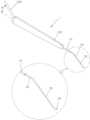
도 1은 본 발명에 의한 백내장 수술용 챠퍼의 사시도.
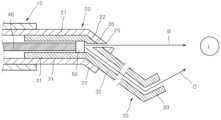
도 2는 본 발명에 의한 백내장 수술용 챠퍼 니들의 일부 단면도.
도 3은 본 발명의 다른 실시예에 의한 백내장 수술용 챠퍼 니들의 일부 단면도.Figure 1 is a perspective view of a chopper for cataract surgery according to the present invention.
Figure 2 is a partial cross-sectional view of the chopper needle for cataract surgery according to the present invention.
Figure 3 is a partial cross-sectional view of a chopper needle for cataract surgery according to another embodiment of the present invention.
이하에서는 첨부 도면을 참조하여 본 발명에 대해서 자세하게 설명한다.Hereinafter, the present invention will be described in detail with reference to the accompanying drawings.
본 명세서에서는 본 발명의 설명에 필요한 최소한의 구성요소만을 설명하며, 본 발명의 본질과 관계가 없는 구성요소는 언급하지 아니한다. 그리고 언급되는 구성요소만을 포함하는 배타적인 의미로 해석되어서는 아니되며 언급되지 않은 다른 구성요소도 포함할 수 있는 비배타적인 의미로 해석되어야 한다.In this specification, only the minimum components necessary for description of the present invention are described, and components that are not related to the essence of the present invention are not mentioned. And it should not be interpreted in an exclusive sense that includes only the mentioned components, but should be interpreted in a non-exclusive sense that may also include other components that are not mentioned.
본 명세서에서 사용되는 “제1”, “제2” 또는 그와 유사한 표현들은 같거나 유사한 구성요소를 구분적으로 표현하기 위해서 또는 본 발명을 구성하는 단계들의 명칭을 구분하기 위해 사용되며, 순서를 의미하거나 복수임을 의미하는 것이 아니다.As used herein, “first,” “second,” or similar expressions are used to separately express the same or similar components or to distinguish the names of steps constituting the present invention, and are used in order. It does not mean that it is meaningful or plural.
본 명세서에서 설명하는 예시적인 실시예는 본 명세서에 개시(開示)되는 장치의 구조, 기능, 제작 및 용도와 방법의 원리에 대한 전반적인 이해를 제공한다. 이러한 하나 이상의 실시예가 첨부 도면에 도시되어 있다. 당업자라면 여기에 구체적으로 기재되고 첨부 도면에 도시되어 있는 장치 및 방법이 비제한적이고 예시적인 실시예이며 본 발명의 권리범위는 특허청구범위에 의해서 정의된다는 점을 이해할 것이다. 하나의 예시적인 실시예와 관련되어 도시되고 설명되는 특징은 다른 실시예의 특징과도 결합될 수 있다. 그러한 수정(modification) 또는 변경(variation)은 본 발명의 권리범위에 포함되도록 의도된다.The exemplary embodiments described herein provide a general understanding of the principles of the structure, function, fabrication and use of the devices and methods disclosed herein. One or more such embodiments are depicted in the accompanying drawings. Those skilled in the art will understand that the devices and methods specifically described herein and shown in the accompanying drawings are non-limiting illustrative embodiments and that the scope of the present invention is defined by the claims. Features shown and described in connection with one example embodiment may also be combined with features of other embodiments. Such modifications or variations are intended to be included within the scope of the present invention.
본 명세서에서 "연결"이라 함은 두 구성요소가 직접 연결되는 것 뿐만 아니라 두 구성요소 사이에 추가적인 다른 구성요소가 개재(介在)하여 연결되는 것도 포함하는 것으로 정의된다.In this specification, “connection” is defined to include not only direct connection of two components, but also connection with another additional component intervening between the two components.
도 1에는 본 발명에 의한 예시적인 백내장 수술용 챠퍼(1)의 사시도가 도시되어 있다.1 shows a perspective view of an
본 발명에 의한 백내장 수술용 챠퍼(1)에서는 핸들(100) 및 챠퍼 니들의 길이 방향을 따라 광섬유(40)가 제공되는데 광섬유(40)에 빛을 공급하는 광 공급 케이블(200)이 핸들(100)의 상류측 단부에 연결된다. 본 명세서에서 "상류"와 "하류"는 광섬유를 통한 광의 진행 방향을 기준으로 정한다. 즉 챠퍼 니들의 단부 즉 빛을 조사하는 쪽이 하류측이 되며, 챠퍼 니들의 단부의 반대 방향 즉 광원쪽 방향이 상류측이 된다.In the chopper (1) for cataract surgery according to the present invention, an optical fiber (40) is provided along the longitudinal direction of the handle (100) and the chopper needle, and the light supply cable (200) that supplies light to the optical fiber (40) is connected to the handle (100). ) is connected to the upstream end of the In this specification, “upstream” and “downstream” are defined based on the direction of light traveling through the optical fiber. That is, the end of the chopper needle, that is, the side that irradiates the light, becomes the downstream side, and the opposite direction to the end of the chopper needle, that is, the direction toward the light source, becomes the upstream side.
광 공급 케이블(200)의 일단부는 광원(도시되지 않음)에 연결되며, 광 공급 케이블(200)의 타단부는 핸들(100)의 상류측 단부에 핸들의 길이 방향에 대해서 소정의 각도(a)를 이루면서 연결될 수 있다. 광 공급 케이블(200)이 소정의 각도(a)를 이루면서 핸들(100)에 연결되면 백내장 수술시에 광 공급 케이블(200)이 시술자의 시야를 방해하는 것을 방지할 수 있는 효과가 있다.One end of the
도 1 및 도 2에 도시된 바와 같이 본 발명에 의한 챠퍼 니들은 핸들(100)에 결합하는 제1 보강 니들(10)과, 제2 보강 니들(20)과, 메인 니들(30)을 포함한다. 메인 니들(30)이 수정체를 쪼개고 제거하는데에 사용된다. 도 1 및 도 2에 도시된 챠퍼 니들은 본 발명을 설명하기 위한 예시적인 챠퍼 니들에 불과하며, 본 발명의 기술적 사상은 다른 형태의 챠퍼 니들에도 적용 가능하다.As shown in Figures 1 and 2, the chopper needle according to the present invention includes a
제1 보강 니들(10)은 핸들(100)에 예를 들어 초음파 융착 또는 접착제를 사용하는 등의 방법으로 결합될 수 있는데, 그 이외의 공지되어 있는 다른 결합 방식으로 결합될 수도 있다.The
제2 보강 니들(20)의 상류측 일부는 제1 보강 니들(10)의 하류측에 삽입되며, 메인 니들(30)의 상류측 일부는 제2 보강 니들(20)의 하류측에 연결된다. 예를 들어, 도 2에 도시된 바와 같이 제2 보강 니들(20)의 상류측 일부가 제1 보강 니들(10)의 하류측에 삽입되고, 메인 니들(30)의 상류측 일부가 제2 보강 니들(20)의 하류측에 삽입되어 서로 연결될 수 있다.The upstream part of the
제2 보강 니들(20)은, 제1 보강 니들(10)과 평행하게 연장하는 제2-1 부분(21)과, 제2-1 부분(21)에 대해서 소정의 각도를 이루는 제2-2 부분(22)을 포함할 수 있다.The
제1 보강 니들(10)과 제2 보강 니들(20)은 예를 들어 의료용 접착제에 의해 서로 결합될 수 있다.The
메인 니들(30)은 제2 보강 니들(20)의 제2-1 부분(21)과 평행한 제3-1 부분(31)과, 제2-2 부분(22)과 평행한 제3-2 부분(32)과, 제3-2 부분(32)과 소정의 각도를 이루는 제3-3 부분(33)을 포함할 수 있다.The
제1 광섬유(44)는, 핸들(100)과, 제1 보강 니들(10)과, 제2 보강 니들(20)과, 메인 니들(30)의 길이 방향을 따라 연장한다. 제1 광섬유(44)는 메인 니들(30)의 단부에서 수정체에 빛을 조사할 수 있는 위치까지 연장할 수 있다. 도 2에는 제1 광섬유(44)가 메인 니들(30)의 단부까지 연장하는 것으로 도시되어 있지만, 메인 니들(30)의 단부에서 수정체에 빛을 조사할 수 있다면 단부 이전까지만 연장해도 무방하다.The first
도 2에는 제1 광섬유(44)가 메인 니들(30)의 단부에서 메인 니들(30)의 길이 방향을 향해 빛을 조사할 수 있는 것으로 도시되어 있지만, 제1 광섬유(44)는 메인 니들(30)의 단부에서 다른 방향 예를 들어, 메인 니들(30)의 길이 방향에 수직인 방향, 또는 길이 방향에 대해서 소정의 각도를 이루는 방향으로 빛을 조사할 수 있도록 제공될 수도 있다. 그리고 도 2에는 제1 광섬유(44)로 단일의 광섬유가 제공되는 것으로 도시되어 있지만 제1 광섬유(44)는 복수 개가 제공될 수도 있다.Although FIG. 2 shows that the first
제1 보강 니들(10), 제2 보강 니들(20) 및 메인 니들(30)은 중공형태일 수 있으며, 제1 광섬유(44)는 그 내부에서 길이 방향을 따라서 연장할 수 있다.The
도 1 및 도 2에는 핸들(100)와 메인 니들(30) 사이에 보강 니들이 2개인 실시예가 도시되어 있지만, 보강 니들은 3개 이상 제공될 수 있으며 그러한 실시예 역시 본 발명의 범위에 속한다. 예를 들어, 제1 보강 니들(10)과 메인 니들(30) 사이에는 단일의 제2 보강 니들(20) 뿐만 아니라 복수 개의 제2 보강 니들(20)이 제공될 수 있다.1 and 2 show an embodiment in which there are two reinforcing needles between the
본 발명은 제1 보강 니들(10)과 제2 보강 니들(20) 없는 챠퍼 니들 또는, 단일의 보강 니들만 제공되는 챠퍼 니들에도 적용 가능하다.The present invention can also be applied to a chopper needle without the
제2 광섬유(42)는 제2 보강 니들(20)과 메인 니들(30)의 두께부의 구멍(25)을 통과하여 메인 니들(30)의 단부보다 상류측에서 외부로 빛을 조사하도록 제공된다. 제2 보강 니들(20)과 메인 니들(30)의 길이에 따라서는 제2 광섬유(42)는 메인 니들(30)의 두께부만 관통하도록 제공될 수도 있다. 또한, 보강 니들이 없이 메인 니들이 핸들에 직접 연결되는 챠퍼 니들에서는 제2 광섬유(42)는 메인 니들(30)의 두께부만 관통할 수 있다.The second
도 2에는 제2 광섬유(42)가 니들의 외부로 돌출되도록 도시되어 있지만, 외부로 빛을 조사할 수 있는 위치라면 니들의 두께부 안쪽에 배치될 수도 있고, 도 2에 도시된 실시예에서는 광섬유의 단부를 제2-2 부분(22)의 외부 형태에 맞도록 깍을 수도 있다.Although the second
도 2에는 제2 광섬유(42)가 단일의 광섬유로 도시되어 있지만 제2 광섬유(42)는 복수 개의 광섬유일 수도 있다.Although the second
제1 광섬유(44)는 수정체(L)를 향해 C 방향으로 빛을 조사하는데 제2 광섬유(42)는 수정체(L)을 향해 B 방향으로 빛을 조사할 수 있다. 제2 광섬유(42)는 제1 광섬유(44)보다 상류측에서 수정체(L)를 향해 빛을 조사하므로 빛의 조사 면적이 증가하는 효과를 기대할 수 있다.The first
그렇게 되면 수정체(L)의 더 넓은 면적에 빛을 조사함으로써 수술자의 시인성이 더 좋아지는 효과가 있다. 설명의 편의를 위해서 도 2에서는 메인 니들(30)의 단부와 수정체(L)의 거리가 멀게 도시되어 있지만 실제로는 메인 니들(30)의 단부는 수정체(L)에 인접하게 배치되며, 제2 광섬유(42)는 그러한 상태에서 수정체(L)에 빛을 조사할 수 있도록 제공된다.This has the effect of improving the operator's visibility by irradiating light to a larger area of the lens (L). For convenience of explanation, the distance between the end of the
제1 광섬유(44)와 제2 광섬유(42)는 수정체(L)가 아닌 임의의 다른 지점을 향해 빛을 조사하도록 제공될 수도 있으며, 서로 평행한 빛을 조사하도록 제공될 수도 있다.The first
제1 광섬유(44)와 제2 광섬유(42)는 동일한 광원으로부터 빛을 공급받을 수도 있고 두 개의 서로 상이한 광원으로부터 빛을 공급받을 수도 있다. 제1 광섬유(44)와 제2 광섬유(42)가 두 개의 상이한 광원으로부터 빛을 공급받는 실시예에서는, 제1 광섬유(44)와 제2 광섬유(42)가 조사하는 빛의 세기(밝기)가 서로 독립적으로 조절될 수 있다. 예를 들어, 제1 광섬유(44)와 제2 광섬유(42)가 조사하는 각각의 빛의 세기를 0에서 광원이 허용하는 최대 밝기까지 임의로 조절할 수 있다.The first
제1 광섬유(44)와 제2 광섬유(42)가 서로 동일한 광원으로부터 빛을 공급받는 실시예에서는, 제1 광섬유(44)와 제2 광섬유(42)가 조사하는 빛의 세기가 같을 수 있다. 그러나 제1 광섬유(44)와 제2 광섬유(42)가 동일한 광원으로부터 빛을 공급받더라도 광섬유의 단면적을 서로 다르게 하거나, 광섬유의 개수를 다르게 함으로써 제1 광섬유(44)와 제2 광섬유(42)가 서로 다른 세기의 빛을 조사하도록 할 수 있다.In an embodiment in which the first
도 3에는 본 발명의 다른 실시예에 의한 백내장 수술용 챠퍼 니들의 일부 단면도가 도시되어 있다. 이 실시예에 의한 백내장 수술용 챠퍼 니들은 광섬유(46)가 핸들(100), 제1 보강 니들(10), 제2 보강 니들(20) 및 메인 니들(30)의 길이 방향을 따라 연장하다가, 메인 니들(30)의 단부보다 상류측에서 광 분기기(beam splitter; 50)에 연결된다. 광섬유(46)가 조사하는 빛은 광 분기기(50)에 의해서 두 갈래로 분기(split)되어 한 갈래의 빛은 메인 니들(30)의 단부에서 제1 광으로서 조사되며, 다른 한 갈래의 빛은 메인 니들(30)의 단부보다 상류측에서 외부로 제2 광으로서 조사된다. 광섬유(46)는 광 분기기(50)에 직접 연결되지 않고 광 분기기(50)의 상류쪽까지만 연장되고 빛을 광 분기기(50)로 조사할 수도 있다.Figure 3 shows a partial cross-sectional view of a chopper needle for cataract surgery according to another embodiment of the present invention. In the chopper needle for cataract surgery according to this embodiment, the
광섬유(46)가 조사하는 빛을 두 갈래로 분기(split)하기 위한 광 분기기(50)로는 예를 들어 프리즘(prism), 라이트가이드(light guide), 또는 하프 미러(half mirror 또는 dichroic mirror) 등을 사용할 수 있다.The
도 4에는 본 발명의 다른 실시예에 의한 백내장 수술용 챠퍼 니들의 일부 단면도가 도시되어 있다. 이 실시예에 의하면, 광섬유(46)가 광 분기기(50)를 지나 두 갈래로 나뉘어서 연장한다. 광 섬유(46)가 광 분기기(50)를 지나서도 연장하는 점에서 도 3의 실시예와 다를 뿐 다른 내용은 도 3의 실시예와 대동소이하므로 자세한 설명은 생략하기로 한다.Figure 4 shows a partial cross-sectional view of a chopper needle for cataract surgery according to another embodiment of the present invention. According to this embodiment, the
이상 첨부 도면을 참고하여 본 발명에 대해서 설명하였지만 본 발명의 권리범위는 후술하는 특허청구범위에 의해 결정되며 전술한 실시예 및/또는 도면에 제한되는 것으로 해석되어서는 아니된다. 그리고 특허청구범위에 기재된 발명의, 당업자에게 자명한 개량, 변경 및 수정도 본 발명의 권리범위에 포함된다는 점이 명백하게 이해되어야 한다.Although the present invention has been described above with reference to the accompanying drawings, the scope of the present invention is determined by the scope of the patent claims described later and should not be construed as being limited to the above-described embodiments and/or drawings. In addition, it should be clearly understood that improvements, changes and modifications of the invention described in the patent claims, which are obvious to those skilled in the art, are also included in the scope of rights of the present invention.
10: 제1 보강 니들
20: 제2 보강 니들
30: 메인 니들
42, 44, 46: 광섬유
50: 광 분기기10: First reinforcement needle
20: Second reinforcement needle
30: Main needle
42, 44, 46: optical fiber
50: Optical splitter
Claims (12)
Translated fromKorean메인 니들 내부에 메인 니들의 길이 방향을 따라 제공되는 광섬유를 포함하며,
광섬유의 빛은 메인 니들의 단부보다 상류측에서 분기되어, 광섬유의 빛의 일부는 메인 니들 단부에서 제1 광으로서 외부로 조사되고, 상류측에서 분기된 다른 일부는 제2 광으로서 외부로 조사되는,
백내장 수술용 챠퍼 니들.
The main needle connected to the handle,
Includes an optical fiber provided inside the main needle along the longitudinal direction of the main needle,
The light of the optical fiber is branched upstream from the end of the main needle, and part of the light of the optical fiber is irradiated to the outside as first light from the end of the main needle, and the other part branched from the upstream side is irradiated to the outside as second light. ,
Chopper needle for cataract surgery.
상기 광섬유는 제1 광을 조사하는 제1 광섬유와, 제2 광을 조사하는 제2 광섬유를 포함하는,
백내장 수술용 챠퍼 니들.
In claim 1,
The optical fiber includes a first optical fiber that irradiates first light and a second optical fiber that radiates second light,
Chopper needle for cataract surgery.
광섬유의 빛을 분기시키는 광 분기기를 더 포함하는,
백내장 수술용 챠퍼 니들.
In claim 1,
Further comprising an optical splitter that diverges the light of the optical fiber,
Chopper needle for cataract surgery.
광 분기기는, 프리즘, 라이트가이드, 또는 하프 미러인,
백내장 수술용 챠퍼 니들.
In claim 4,
The optical splitter is a prism, light guide, or half mirror,
Chopper needle for cataract surgery.
제1 광의 밝기와 제2 광의 밝기는 서로 독립적으로 조절되는,
백내장 수술용 챠퍼 니들.
In claim 1,
The brightness of the first light and the brightness of the second light are adjusted independently of each other,
Chopper needle for cataract surgery.
제1 광 및 제2 광은 외부의 동일한 지점을 조사하는,
백내장 수술용 챠퍼 니들.
In claim 1,
The first light and the second light irradiate the same external point,
Chopper needle for cataract surgery.
핸들과 메인 니들 사이에 제공되는 제2 보강 니들을 더 포함하며,
제2 보강 니들의 하류측에는 메인 니들의 상류측 일부가 연결되고,
제2 보강 니들의 상류측은 핸들에 연결되는,
백내장 수술용 챠퍼 니들.
In claim 1,
It further includes a second reinforcement needle provided between the handle and the main needle,
A portion of the upstream side of the main needle is connected to the downstream side of the second reinforcement needle,
The upstream side of the second reinforcement needle is connected to the handle,
Chopper needle for cataract surgery.
핸들과 제2 보강 니들 사이에 제공되는 제1 보강 니들을 더 포함하며,
제1 보강 니들의 하류측에는 제2 보강 니들의 상류측 일부가 연결되고,
제1 보강 니들의 상류측은 핸들에 연결되는,
백내장 수술용 챠퍼 니들.
In claim 8,
It further includes a first reinforcement needle provided between the handle and the second reinforcement needle,
A portion of the upstream side of the second reinforcement needle is connected to the downstream side of the first reinforcement needle,
The upstream side of the first reinforcement needle is connected to the handle,
Chopper needle for cataract surgery.
제1 보강 니들은 직선형이며,
제2 보강 니들은 제1 보강 니들과 동축으로 연장하는 제2-1 부분과, 상기 제2-1 부분에 대해 소정의 각도를 이루며 제2-1 부분의 하류측 단부로부터 연장하는 제2-2 부분을 포함하며,
메인 니들은, 제2 보강 니들의 제2-1 부분와 동축으로 연장하는 제3-1 부분과, 제2-2 부분과 동축이며 제3-1 부분에 대해 소정의 각도를 이루며 제3-1 부분의 하류측 단부로부터 연장하는 제3-2 부분을 포함하며,
제2 광은, 제2-2 부분과 제3-2 부분을 관통하여 외부를 향해 조사되는,
백내장 수술용 챠퍼 니들.
In claim 9,
The first reinforcing needle is straight,
The second reinforcement needle includes a 2-1 part extending coaxially with the first reinforcement needle, and a 2-2 part extending from the downstream end of the 2-1 part at a predetermined angle with respect to the 2-1 part. Contains parts,
The main needle includes a 3-1 part that extends coaxially with the 2-1 part of the second reinforcement needle, is coaxial with the 2-2 part, and forms a predetermined angle with respect to the 3-1 part. It includes a 3-2 portion extending from the downstream end of,
The second light penetrates the 2-2 portion and the 3-2 portion and is irradiated toward the outside.
Chopper needle for cataract surgery.
메인 니들은,
제3-2 부분과 소정의 각도를 이루도록 연장하는 제3-3 부분을 더 포함하는,
백내장 수술용 챠퍼 니들.
In claim 10,
The main needle is,
Further comprising a 3-3 part extending to form a predetermined angle with the 3-2 part,
Chopper needle for cataract surgery.
Priority Applications (1)
| Application Number | Priority Date | Filing Date | Title |
|---|---|---|---|
| KR1020210064160AKR102631863B1 (en) | 2021-05-18 | 2021-05-18 | Chopper Needle for Cataract Surgery |
Applications Claiming Priority (1)
| Application Number | Priority Date | Filing Date | Title |
|---|---|---|---|
| KR1020210064160AKR102631863B1 (en) | 2021-05-18 | 2021-05-18 | Chopper Needle for Cataract Surgery |
Publications (2)
| Publication Number | Publication Date |
|---|---|
| KR20220156305A KR20220156305A (en) | 2022-11-25 |
| KR102631863B1true KR102631863B1 (en) | 2024-01-31 |
Family
ID=84237246
Family Applications (1)
| Application Number | Title | Priority Date | Filing Date |
|---|---|---|---|
| KR1020210064160AActiveKR102631863B1 (en) | 2021-05-18 | 2021-05-18 | Chopper Needle for Cataract Surgery |
Country Status (1)
| Country | Link |
|---|---|
| KR (1) | KR102631863B1 (en) |
Families Citing this family (1)
| Publication number | Priority date | Publication date | Assignee | Title |
|---|---|---|---|---|
| KR20250140821A (en)* | 2024-03-19 | 2025-09-26 | 가톨릭대학교 산학협력단 | Chopper for cataract surgery |
Citations (3)
| Publication number | Priority date | Publication date | Assignee | Title |
|---|---|---|---|---|
| JP2013537462A (en)* | 2010-08-13 | 2013-10-03 | アルコン リサーチ, リミテッド | Dual mode lighting method for surgical instruments |
| JP2018537214A (en)* | 2015-12-14 | 2018-12-20 | ノバルティス アーゲー | Single-port hybrid gauge surgical device and method |
| JP2020044289A (en)* | 2018-09-21 | 2020-03-26 | マニー株式会社 | Ophthalmic surgical instrument |
Family Cites Families (1)
| Publication number | Priority date | Publication date | Assignee | Title |
|---|---|---|---|---|
| KR101478463B1 (en) | 2013-10-10 | 2014-12-31 | 가천대학교 산학협력단 | An illumination chopper |
- 2021
- 2021-05-18KRKR1020210064160Apatent/KR102631863B1/enactiveActive
Patent Citations (3)
| Publication number | Priority date | Publication date | Assignee | Title |
|---|---|---|---|---|
| JP2013537462A (en)* | 2010-08-13 | 2013-10-03 | アルコン リサーチ, リミテッド | Dual mode lighting method for surgical instruments |
| JP2018537214A (en)* | 2015-12-14 | 2018-12-20 | ノバルティス アーゲー | Single-port hybrid gauge surgical device and method |
| JP2020044289A (en)* | 2018-09-21 | 2020-03-26 | マニー株式会社 | Ophthalmic surgical instrument |
Also Published As
| Publication number | Publication date |
|---|---|
| KR20220156305A (en) | 2022-11-25 |
Similar Documents
| Publication | Publication Date | Title |
|---|---|---|
| ES3029960T3 (en) | Multiple-input-coupled illuminated multi-spot laser probe | |
| US8029499B2 (en) | Endprobe for intraocular treatment of the eye | |
| KR101862809B1 (en) | White coherent laser light launched into nano fibers for surgical illumination | |
| JP3073994B2 (en) | Variable irradiation angle laser irradiation device | |
| JP2018524028A (en) | Perimeter lighting fixture | |
| EP3155990B1 (en) | Bone nail apparatus | |
| JP2014519869A5 (en) | ||
| US20210282973A1 (en) | Illumination chopper | |
| KR102631863B1 (en) | Chopper Needle for Cataract Surgery | |
| KR101529954B1 (en) | Device and method for cutting the cornea of a human eye by means of cuts using focused pulsed laser radiation | |
| US10441156B2 (en) | Application of highly scattering materials to surgical illumination | |
| KR102582221B1 (en) | Chopper Needle for Cataract Surgery, Method for Manufacturing the Chopper Needle and Chopper for Cataract Surguery Comprising the Same Chopper Needle | |
| KR102631851B1 (en) | Chopper Needle for Cataract Surgery | |
| KR101735208B1 (en) | Multiplexing light source apparatus for microscope | |
| KR20240057054A (en) | Chopper Needle for Ophthalmologic Surgery Which Comprises Auxiliary Light | |
| CN120065406B (en) | Lighting optical fiber and devices | |
| KR101607404B1 (en) | Multiplexing light source apparatus for microscope | |
| US20180337507A1 (en) | A laser safety adaptor for use in laser based imaging systems and related devices | |
| JP7127268B2 (en) | optical coupler | |
| US20090018563A1 (en) | Stripping device for removal of varicose veins | |
| CN216535539U (en) | Lacrimal sac positioner | |
| KR20230134299A (en) | Wireless Illumination Chopper for Ophthalmic Surgery | |
| CN106999039A (en) | Lens combination for eye examination | |
| KR20230160628A (en) | Laser irradiation device | |
| WO2020012697A1 (en) | Endoscope illumination optics |
Legal Events
| Date | Code | Title | Description |
|---|---|---|---|
| PA0109 | Patent application | St.27 status event code:A-0-1-A10-A12-nap-PA0109 | |
| PA0201 | Request for examination | St.27 status event code:A-1-2-D10-D11-exm-PA0201 | |
| R18-X000 | Changes to party contact information recorded | St.27 status event code:A-3-3-R10-R18-oth-X000 | |
| D13-X000 | Search requested | St.27 status event code:A-1-2-D10-D13-srh-X000 | |
| PG1501 | Laying open of application | St.27 status event code:A-1-1-Q10-Q12-nap-PG1501 | |
| D14-X000 | Search report completed | St.27 status event code:A-1-2-D10-D14-srh-X000 | |
| E902 | Notification of reason for refusal | ||
| PE0902 | Notice of grounds for rejection | St.27 status event code:A-1-2-D10-D21-exm-PE0902 | |
| T11-X000 | Administrative time limit extension requested | St.27 status event code:U-3-3-T10-T11-oth-X000 | |
| T11-X000 | Administrative time limit extension requested | St.27 status event code:U-3-3-T10-T11-oth-X000 | |
| E13-X000 | Pre-grant limitation requested | St.27 status event code:A-2-3-E10-E13-lim-X000 | |
| P11-X000 | Amendment of application requested | St.27 status event code:A-2-2-P10-P11-nap-X000 | |
| P13-X000 | Application amended | St.27 status event code:A-2-2-P10-P13-nap-X000 | |
| E701 | Decision to grant or registration of patent right | ||
| PE0701 | Decision of registration | St.27 status event code:A-1-2-D10-D22-exm-PE0701 | |
| PR0701 | Registration of establishment | St.27 status event code:A-2-4-F10-F11-exm-PR0701 | |
| PR1002 | Payment of registration fee | St.27 status event code:A-2-2-U10-U11-oth-PR1002 Fee payment year number:1 | |
| PG1601 | Publication of registration | St.27 status event code:A-4-4-Q10-Q13-nap-PG1601 |