KR102631275B1 - Low profile rear lamp applique assembly - Google Patents
Low profile rear lamp applique assemblyDownload PDFInfo
- Publication number
- KR102631275B1 KR102631275B1KR1020207027910AKR20207027910AKR102631275B1KR 102631275 B1KR102631275 B1KR 102631275B1KR 1020207027910 AKR1020207027910 AKR 1020207027910AKR 20207027910 AKR20207027910 AKR 20207027910AKR 102631275 B1KR102631275 B1KR 102631275B1
- Authority
- KR
- South Korea
- Prior art keywords
- lift gate
- assembly
- connector
- rear lamp
- housing
- Prior art date
- Legal status (The legal status is an assumption and is not a legal conclusion. Google has not performed a legal analysis and makes no representation as to the accuracy of the status listed.)
- Active
Links
- 238000007789sealingMethods0.000claimsabstractdescription40
- 238000000034methodMethods0.000claimsabstractdescription7
- 239000000853adhesiveSubstances0.000claimsdescription33
- 230000001070adhesive effectEffects0.000claimsdescription33
- 230000013011matingEffects0.000claimsdescription30
- 238000009434installationMethods0.000claimsdescription6
- 230000003014reinforcing effectEffects0.000claims1
- XLYOFNOQVPJJNP-UHFFFAOYSA-NwaterSubstancesOXLYOFNOQVPJJNP-UHFFFAOYSA-N0.000abstractdescription11
- 238000004519manufacturing processMethods0.000abstractdescription2
- 239000000463materialSubstances0.000description13
- 230000008901benefitEffects0.000description9
- 238000004026adhesive bondingMethods0.000description5
- 239000000203mixtureSubstances0.000description4
- 238000003466weldingMethods0.000description4
- 230000000694effectsEffects0.000description3
- 230000000712assemblyEffects0.000description2
- 238000000429assemblyMethods0.000description2
- 238000007667floatingMethods0.000description2
- 238000005188flotationMethods0.000description2
- 238000005304joiningMethods0.000description2
- 238000012986modificationMethods0.000description2
- 230000004048modificationEffects0.000description2
- 238000002604ultrasonographyMethods0.000description2
- 238000013459approachMethods0.000description1
- 238000004140cleaningMethods0.000description1
- 239000002131composite materialSubstances0.000description1
- 239000000428dustSubstances0.000description1
- 230000008030eliminationEffects0.000description1
- 238000003379elimination reactionMethods0.000description1
- 238000005516engineering processMethods0.000description1
- 239000006260foamSubstances0.000description1
- 238000002347injectionMethods0.000description1
- 239000007924injectionSubstances0.000description1
- 230000000873masking effectEffects0.000description1
- 229920000515polycarbonatePolymers0.000description1
- 239000004417polycarbonateSubstances0.000description1
- 239000000243solutionSubstances0.000description1
- 239000000725suspensionSubstances0.000description1
Images


Classifications
- B—PERFORMING OPERATIONS; TRANSPORTING
- B60—VEHICLES IN GENERAL
- B60Q—ARRANGEMENT OF SIGNALLING OR LIGHTING DEVICES, THE MOUNTING OR SUPPORTING THEREOF OR CIRCUITS THEREFOR, FOR VEHICLES IN GENERAL
- B60Q1/00—Arrangement of optical signalling or lighting devices, the mounting or supporting thereof or circuits therefor
- B60Q1/26—Arrangement of optical signalling or lighting devices, the mounting or supporting thereof or circuits therefor the devices being primarily intended to indicate the vehicle, or parts thereof, or to give signals, to other traffic
- B60Q1/30—Arrangement of optical signalling or lighting devices, the mounting or supporting thereof or circuits therefor the devices being primarily intended to indicate the vehicle, or parts thereof, or to give signals, to other traffic for indicating rear of vehicle, e.g. by means of reflecting surfaces
- B60Q1/301—Arrangement of optical signalling or lighting devices, the mounting or supporting thereof or circuits therefor the devices being primarily intended to indicate the vehicle, or parts thereof, or to give signals, to other traffic for indicating rear of vehicle, e.g. by means of reflecting surfaces by means of surfaces, e.g. metal plate, reflecting the light of an external light source
- B60Q1/3015—Arrangement of optical signalling or lighting devices, the mounting or supporting thereof or circuits therefor the devices being primarily intended to indicate the vehicle, or parts thereof, or to give signals, to other traffic for indicating rear of vehicle, e.g. by means of reflecting surfaces by means of surfaces, e.g. metal plate, reflecting the light of an external light source combined with a lamp
- B—PERFORMING OPERATIONS; TRANSPORTING
- B60—VEHICLES IN GENERAL
- B60Q—ARRANGEMENT OF SIGNALLING OR LIGHTING DEVICES, THE MOUNTING OR SUPPORTING THEREOF OR CIRCUITS THEREFOR, FOR VEHICLES IN GENERAL
- B60Q1/00—Arrangement of optical signalling or lighting devices, the mounting or supporting thereof or circuits therefor
- B60Q1/0088—Details of electrical connections
- B—PERFORMING OPERATIONS; TRANSPORTING
- B60—VEHICLES IN GENERAL
- B60J—WINDOWS, WINDSCREENS, NON-FIXED ROOFS, DOORS, OR SIMILAR DEVICES FOR VEHICLES; REMOVABLE EXTERNAL PROTECTIVE COVERINGS SPECIALLY ADAPTED FOR VEHICLES
- B60J5/00—Doors
- B60J5/10—Doors arranged at the vehicle rear
- B—PERFORMING OPERATIONS; TRANSPORTING
- B60—VEHICLES IN GENERAL
- B60Q—ARRANGEMENT OF SIGNALLING OR LIGHTING DEVICES, THE MOUNTING OR SUPPORTING THEREOF OR CIRCUITS THEREFOR, FOR VEHICLES IN GENERAL
- B60Q1/00—Arrangement of optical signalling or lighting devices, the mounting or supporting thereof or circuits therefor
- B60Q1/0088—Details of electrical connections
- B60Q1/0094—Arrangement of electronic circuits separated from the light source, e.g. mounting of housings for starter circuits for discharge lamps
- B—PERFORMING OPERATIONS; TRANSPORTING
- B60—VEHICLES IN GENERAL
- B60Q—ARRANGEMENT OF SIGNALLING OR LIGHTING DEVICES, THE MOUNTING OR SUPPORTING THEREOF OR CIRCUITS THEREFOR, FOR VEHICLES IN GENERAL
- B60Q1/00—Arrangement of optical signalling or lighting devices, the mounting or supporting thereof or circuits therefor
- B60Q1/02—Arrangement of optical signalling or lighting devices, the mounting or supporting thereof or circuits therefor the devices being primarily intended to illuminate the way ahead or to illuminate other areas of way or environments
- B60Q1/22—Arrangement of optical signalling or lighting devices, the mounting or supporting thereof or circuits therefor the devices being primarily intended to illuminate the way ahead or to illuminate other areas of way or environments for reverse drive
- B—PERFORMING OPERATIONS; TRANSPORTING
- B60—VEHICLES IN GENERAL
- B60Q—ARRANGEMENT OF SIGNALLING OR LIGHTING DEVICES, THE MOUNTING OR SUPPORTING THEREOF OR CIRCUITS THEREFOR, FOR VEHICLES IN GENERAL
- B60Q1/00—Arrangement of optical signalling or lighting devices, the mounting or supporting thereof or circuits therefor
- B60Q1/26—Arrangement of optical signalling or lighting devices, the mounting or supporting thereof or circuits therefor the devices being primarily intended to indicate the vehicle, or parts thereof, or to give signals, to other traffic
- B60Q1/2619—Arrangement of optical signalling or lighting devices, the mounting or supporting thereof or circuits therefor the devices being primarily intended to indicate the vehicle, or parts thereof, or to give signals, to other traffic built in the vehicle body
- B60Q1/2623—Details of the fastening means
- B60Q1/263—Snap-in fasteners
- B—PERFORMING OPERATIONS; TRANSPORTING
- B60—VEHICLES IN GENERAL
- B60Q—ARRANGEMENT OF SIGNALLING OR LIGHTING DEVICES, THE MOUNTING OR SUPPORTING THEREOF OR CIRCUITS THEREFOR, FOR VEHICLES IN GENERAL
- B60Q1/00—Arrangement of optical signalling or lighting devices, the mounting or supporting thereof or circuits therefor
- B60Q1/26—Arrangement of optical signalling or lighting devices, the mounting or supporting thereof or circuits therefor the devices being primarily intended to indicate the vehicle, or parts thereof, or to give signals, to other traffic
- B60Q1/2619—Arrangement of optical signalling or lighting devices, the mounting or supporting thereof or circuits therefor the devices being primarily intended to indicate the vehicle, or parts thereof, or to give signals, to other traffic built in the vehicle body
- B60Q1/2638—Positioning the device housing by indexing means separate from the fastening means, e.g. pins, rails
- B—PERFORMING OPERATIONS; TRANSPORTING
- B60—VEHICLES IN GENERAL
- B60Q—ARRANGEMENT OF SIGNALLING OR LIGHTING DEVICES, THE MOUNTING OR SUPPORTING THEREOF OR CIRCUITS THEREFOR, FOR VEHICLES IN GENERAL
- B60Q1/00—Arrangement of optical signalling or lighting devices, the mounting or supporting thereof or circuits therefor
- B60Q1/26—Arrangement of optical signalling or lighting devices, the mounting or supporting thereof or circuits therefor the devices being primarily intended to indicate the vehicle, or parts thereof, or to give signals, to other traffic
- B60Q1/2619—Arrangement of optical signalling or lighting devices, the mounting or supporting thereof or circuits therefor the devices being primarily intended to indicate the vehicle, or parts thereof, or to give signals, to other traffic built in the vehicle body
- B60Q1/2653—Arrangement of optical signalling or lighting devices, the mounting or supporting thereof or circuits therefor the devices being primarily intended to indicate the vehicle, or parts thereof, or to give signals, to other traffic built in the vehicle body with arrangement for sealing the device with respect to the vehicle body, or for concealing gaps between the device and the vehicle body
- B—PERFORMING OPERATIONS; TRANSPORTING
- B60—VEHICLES IN GENERAL
- B60Q—ARRANGEMENT OF SIGNALLING OR LIGHTING DEVICES, THE MOUNTING OR SUPPORTING THEREOF OR CIRCUITS THEREFOR, FOR VEHICLES IN GENERAL
- B60Q1/00—Arrangement of optical signalling or lighting devices, the mounting or supporting thereof or circuits therefor
- B60Q1/26—Arrangement of optical signalling or lighting devices, the mounting or supporting thereof or circuits therefor the devices being primarily intended to indicate the vehicle, or parts thereof, or to give signals, to other traffic
- B60Q1/2696—Mounting of devices using LEDs
- B—PERFORMING OPERATIONS; TRANSPORTING
- B60—VEHICLES IN GENERAL
- B60Q—ARRANGEMENT OF SIGNALLING OR LIGHTING DEVICES, THE MOUNTING OR SUPPORTING THEREOF OR CIRCUITS THEREFOR, FOR VEHICLES IN GENERAL
- B60Q1/00—Arrangement of optical signalling or lighting devices, the mounting or supporting thereof or circuits therefor
- B60Q1/26—Arrangement of optical signalling or lighting devices, the mounting or supporting thereof or circuits therefor the devices being primarily intended to indicate the vehicle, or parts thereof, or to give signals, to other traffic
- B60Q1/30—Arrangement of optical signalling or lighting devices, the mounting or supporting thereof or circuits therefor the devices being primarily intended to indicate the vehicle, or parts thereof, or to give signals, to other traffic for indicating rear of vehicle, e.g. by means of reflecting surfaces
- B60Q1/304—Adaptations of signalling devices having a part on the vehicle body and another on the boot door
- B—PERFORMING OPERATIONS; TRANSPORTING
- B60—VEHICLES IN GENERAL
- B60R—VEHICLES, VEHICLE FITTINGS, OR VEHICLE PARTS, NOT OTHERWISE PROVIDED FOR
- B60R16/00—Electric or fluid circuits specially adapted for vehicles and not otherwise provided for; Arrangement of elements of electric or fluid circuits specially adapted for vehicles and not otherwise provided for
- B60R16/02—Electric or fluid circuits specially adapted for vehicles and not otherwise provided for; Arrangement of elements of electric or fluid circuits specially adapted for vehicles and not otherwise provided for electric constitutive elements
- B60R16/0207—Wire harnesses
- B60R16/0215—Protecting, fastening and routing means therefor
- F—MECHANICAL ENGINEERING; LIGHTING; HEATING; WEAPONS; BLASTING
- F21—LIGHTING
- F21S—NON-PORTABLE LIGHTING DEVICES; SYSTEMS THEREOF; VEHICLE LIGHTING DEVICES SPECIALLY ADAPTED FOR VEHICLE EXTERIORS
- F21S43/00—Signalling devices specially adapted for vehicle exteriors, e.g. brake lamps, direction indicator lights or reversing lights
- F21S43/10—Signalling devices specially adapted for vehicle exteriors, e.g. brake lamps, direction indicator lights or reversing lights characterised by the light source
- F21S43/13—Signalling devices specially adapted for vehicle exteriors, e.g. brake lamps, direction indicator lights or reversing lights characterised by the light source characterised by the type of light source
- F21S43/14—Light emitting diodes [LED]
- F—MECHANICAL ENGINEERING; LIGHTING; HEATING; WEAPONS; BLASTING
- F21—LIGHTING
- F21S—NON-PORTABLE LIGHTING DEVICES; SYSTEMS THEREOF; VEHICLE LIGHTING DEVICES SPECIALLY ADAPTED FOR VEHICLE EXTERIORS
- F21S43/00—Signalling devices specially adapted for vehicle exteriors, e.g. brake lamps, direction indicator lights or reversing lights
- F21S43/10—Signalling devices specially adapted for vehicle exteriors, e.g. brake lamps, direction indicator lights or reversing lights characterised by the light source
- F21S43/19—Attachment of light sources or lamp holders
- F21S43/195—Details of lamp holders, terminals or connectors
- F—MECHANICAL ENGINEERING; LIGHTING; HEATING; WEAPONS; BLASTING
- F21—LIGHTING
- F21S—NON-PORTABLE LIGHTING DEVICES; SYSTEMS THEREOF; VEHICLE LIGHTING DEVICES SPECIALLY ADAPTED FOR VEHICLE EXTERIORS
- F21S43/00—Signalling devices specially adapted for vehicle exteriors, e.g. brake lamps, direction indicator lights or reversing lights
- F21S43/20—Signalling devices specially adapted for vehicle exteriors, e.g. brake lamps, direction indicator lights or reversing lights characterised by refractors, transparent cover plates, light guides or filters
- F21S43/26—Refractors, transparent cover plates, light guides or filters not provided in groups F21S43/235 - F21S43/255
- F—MECHANICAL ENGINEERING; LIGHTING; HEATING; WEAPONS; BLASTING
- F21—LIGHTING
- F21S—NON-PORTABLE LIGHTING DEVICES; SYSTEMS THEREOF; VEHICLE LIGHTING DEVICES SPECIALLY ADAPTED FOR VEHICLE EXTERIORS
- F21S43/00—Signalling devices specially adapted for vehicle exteriors, e.g. brake lamps, direction indicator lights or reversing lights
- F21S43/30—Signalling devices specially adapted for vehicle exteriors, e.g. brake lamps, direction indicator lights or reversing lights characterised by reflectors
- F21S43/31—Optical layout thereof
- F—MECHANICAL ENGINEERING; LIGHTING; HEATING; WEAPONS; BLASTING
- F21—LIGHTING
- F21S—NON-PORTABLE LIGHTING DEVICES; SYSTEMS THEREOF; VEHICLE LIGHTING DEVICES SPECIALLY ADAPTED FOR VEHICLE EXTERIORS
- F21S43/00—Signalling devices specially adapted for vehicle exteriors, e.g. brake lamps, direction indicator lights or reversing lights
- F21S43/30—Signalling devices specially adapted for vehicle exteriors, e.g. brake lamps, direction indicator lights or reversing lights characterised by reflectors
- F21S43/37—Attachment thereof
- F—MECHANICAL ENGINEERING; LIGHTING; HEATING; WEAPONS; BLASTING
- F21—LIGHTING
- F21S—NON-PORTABLE LIGHTING DEVICES; SYSTEMS THEREOF; VEHICLE LIGHTING DEVICES SPECIALLY ADAPTED FOR VEHICLE EXTERIORS
- F21S43/00—Signalling devices specially adapted for vehicle exteriors, e.g. brake lamps, direction indicator lights or reversing lights
- F21S43/40—Signalling devices specially adapted for vehicle exteriors, e.g. brake lamps, direction indicator lights or reversing lights characterised by the combination of reflectors and refractors
- F—MECHANICAL ENGINEERING; LIGHTING; HEATING; WEAPONS; BLASTING
- F21—LIGHTING
- F21S—NON-PORTABLE LIGHTING DEVICES; SYSTEMS THEREOF; VEHICLE LIGHTING DEVICES SPECIALLY ADAPTED FOR VEHICLE EXTERIORS
- F21S45/00—Arrangements within vehicle lighting devices specially adapted for vehicle exteriors, for purposes other than emission or distribution of light
- F—MECHANICAL ENGINEERING; LIGHTING; HEATING; WEAPONS; BLASTING
- F21—LIGHTING
- F21V—FUNCTIONAL FEATURES OR DETAILS OF LIGHTING DEVICES OR SYSTEMS THEREOF; STRUCTURAL COMBINATIONS OF LIGHTING DEVICES WITH OTHER ARTICLES, NOT OTHERWISE PROVIDED FOR
- F21V21/00—Supporting, suspending, or attaching arrangements for lighting devices; Hand grips
- F21V21/34—Supporting elements displaceable along a guiding element
- F—MECHANICAL ENGINEERING; LIGHTING; HEATING; WEAPONS; BLASTING
- F21—LIGHTING
- F21V—FUNCTIONAL FEATURES OR DETAILS OF LIGHTING DEVICES OR SYSTEMS THEREOF; STRUCTURAL COMBINATIONS OF LIGHTING DEVICES WITH OTHER ARTICLES, NOT OTHERWISE PROVIDED FOR
- F21V23/00—Arrangement of electric circuit elements in or on lighting devices
- F21V23/06—Arrangement of electric circuit elements in or on lighting devices the elements being coupling devices, e.g. connectors
- F—MECHANICAL ENGINEERING; LIGHTING; HEATING; WEAPONS; BLASTING
- F21—LIGHTING
- F21V—FUNCTIONAL FEATURES OR DETAILS OF LIGHTING DEVICES OR SYSTEMS THEREOF; STRUCTURAL COMBINATIONS OF LIGHTING DEVICES WITH OTHER ARTICLES, NOT OTHERWISE PROVIDED FOR
- F21V3/00—Globes; Bowls; Cover glasses
- H—ELECTRICITY
- H01—ELECTRIC ELEMENTS
- H01R—ELECTRICALLY-CONDUCTIVE CONNECTIONS; STRUCTURAL ASSOCIATIONS OF A PLURALITY OF MUTUALLY-INSULATED ELECTRICAL CONNECTING ELEMENTS; COUPLING DEVICES; CURRENT COLLECTORS
- H01R13/00—Details of coupling devices of the kinds covered by groups H01R12/70 or H01R24/00 - H01R33/00
- H01R13/46—Bases; Cases
- H01R13/52—Dustproof, splashproof, drip-proof, waterproof, or flameproof cases
- H01R13/5219—Sealing means between coupling parts, e.g. interfacial seal
- F—MECHANICAL ENGINEERING; LIGHTING; HEATING; WEAPONS; BLASTING
- F21—LIGHTING
- F21Y—INDEXING SCHEME ASSOCIATED WITH SUBCLASSES F21K, F21L, F21S and F21V, RELATING TO THE FORM OR THE KIND OF THE LIGHT SOURCES OR OF THE COLOUR OF THE LIGHT EMITTED
- F21Y2115/00—Light-generating elements of semiconductor light sources
- F21Y2115/10—Light-emitting diodes [LED]
- H—ELECTRICITY
- H01—ELECTRIC ELEMENTS
- H01R—ELECTRICALLY-CONDUCTIVE CONNECTIONS; STRUCTURAL ASSOCIATIONS OF A PLURALITY OF MUTUALLY-INSULATED ELECTRICAL CONNECTING ELEMENTS; COUPLING DEVICES; CURRENT COLLECTORS
- H01R2201/00—Connectors or connections adapted for particular applications
- H01R2201/26—Connectors or connections adapted for particular applications for vehicles
Landscapes
- Engineering & Computer Science (AREA)
- Mechanical Engineering (AREA)
- General Engineering & Computer Science (AREA)
- Physics & Mathematics (AREA)
- Microelectronics & Electronic Packaging (AREA)
- Optics & Photonics (AREA)
- Lighting Device Outwards From Vehicle And Optical Signal (AREA)
- Non-Portable Lighting Devices Or Systems Thereof (AREA)
Abstract
Translated fromKorean
Description
Translated fromKorean관련 출원에 대한 상호 참조Cross-reference to related applications
본 출원은 2016년 3월 6일자로 출원된 미국 가출원 제62/639,268호 및 2018년 11월 8일자로 출원된 미국 가출원 제62/757,527호에 대한 우선권을 주장하는 PCT 국제 특허 출원이다. 상기 출원들의 전체 개시는 본 명세서에 참조로 포함된다.This application is a PCT international patent application that claims priority to U.S. Provisional Application No. 62/639,268, filed on March 6, 2016, and U.S. Provisional Application No. 62/757,527, filed on November 8, 2018. The entire disclosures of these applications are incorporated herein by reference.
발명의 분야field of invention
본 발명은 로우 프로파일 램프 포켓에 관한 것이다. 특히, 후방 램프 아플리케 조립체가 접착식으로 접합된 리프트 게이트 모듈에 관한 것이다.The present invention relates to low profile lamp pockets. In particular, it relates to a lift gate module with an adhesively bonded rear lamp appliqué assembly.
램프 조립체를 리프트 게이트 구조에 연결하는 것을 최적화하려는 시도가 이루어졌다. 그러나, 체결구, 로케이터, 및 리프트 게이트 내부 패널 구조 상의 밀봉 침해에 문제가 있다. 현재, 공지된 램프 서브 조립체 자체는, 리프트 게이트에 대한 최종 램프 조립체와 함께, 다수의 구입 체결구를 필요로 한다. 현재 램프 서브 조립체 자체는, 리프트 게이트에 대한 최종 조립체와 함께, 또한 램프 내에 그리고 리프트 게이트 폐쇄에 대한 수밀식 밀봉을 유지하기 위해 다수의 밀봉 개스킷을 필요로 한다. 밀봉 개스킷은 비용 증가, 자재 취급, 복잡성, 부품 중량 및 조립 단계를 포함하여 몇 가지 단점이 있다.Attempts were made to optimize the connection of the lamp assembly to the lift gate structure. However, there are issues with seal breaches on the fasteners, locators, and lift gate internal panel structures. Currently, the known ramp subassemblies themselves, along with the final ramp assembly to the lift gate, require multiple off-the-shelf fasteners. Currently the ramp sub-assembly itself, along with the final assembly to the lift gate, also requires multiple sealing gaskets to maintain a watertight seal within the ramp and to the lift gate closure. Sealing gaskets have several drawbacks, including increased cost, material handling, complexity, part weight, and assembly steps.
따라서, 추가된 체결구, 로케이터 핀 및 밀봉 개스킷의 제거를 포함하는 설계에 대한 요구가 본 기술 분야에 남아 있다. Accordingly, a need remains in the art for designs that include the elimination of added fasteners, locator pins, and sealing gaskets.
본 발명은 다수의 개스킷을 조립하는 데에 드는 비용, 질량 및 노동력을 제거하거나 감소시키는 일체로 접합된 설계를 제공한다. 본 발명은 또한 필요한 구성요소 보유 뿐만 아니라 램프 구성요소 및 리프트 게이트 조립체를 위한 수밀식 밀봉을 제공하면서, 치수 무결성을 유지하기 위해 로봇식으로 제어될 수 있는 접착제 접합 부착을 허용하는 비용 효율적인 제조 방법의 사용을 가능하게 한다.The present invention provides an integrally bonded design that eliminates or reduces the cost, mass and labor of assembling multiple gaskets. The present invention also provides a cost-effective manufacturing method that allows adhesive bond attachment that can be robotically controlled to maintain dimensional integrity while providing a watertight seal for the ramp components and lift gate assembly as well as retaining the necessary components. Makes use possible.
본 발명의 바람직한 실시예에 따르면, 예시적인 부착은 접착제 또는 체결구가 필요없이 완전히 스냅 부착된 램프를 포함한다. 게다가, 리프트 게이트에 대한 자체 결합 전기 램프 전기 커넥터가 제공된다. 따라서, 느슨한 와이어 하네스를 램프에 연결하기 위한 손 접근 구멍이 필요하지 않다.According to a preferred embodiment of the present invention, an exemplary attachment includes a lamp that is completely snap attached without the need for adhesives or fasteners. Additionally, self-associating electric lamp electrical connectors for the lift gate are provided. Therefore, there is no need for a hand access hole to connect a loose wire harness to the lamp.
본 발명의 추가 적용 분야는 이후에 제공되는 상세한 설명으로부터 명백해질 것이다. 상세한 설명 및 특정 예는, 본 발명의 바람직한 실시예를 나타내지만, 단지 예시의 목적을 위한 것이며 본 발명의 범위를 제한하도록 의도되지 않는다는 것을 이해해야 한다.Further areas of applicability of the invention will become apparent from the detailed description provided hereinafter. It should be understood that the detailed description and specific examples, while showing preferred embodiments of the invention, are for illustrative purposes only and are not intended to limit the scope of the invention.
본 발명은 상세한 설명 및 첨부 도면으로부터 보다 완전하게 이해될 것이며,
도 1은 리프트 게이트 조립체에 연결된 종래의 후방 램프 아플리케 조립체의 단면도이고;
도 2는 본 발명에 따른 리프트 게이트 조립체에 연결된 후방 램프 아플리케 조립체의 단면도이며;
도 3은, 본 발명에 따라, 리프트 게이트 조립체에 접합된 도 2의 후방 램프 아플리케 조립체의 단면도이고;
도 4는, 본 발명에 따라, 리프트 게이트 조립체에 접합된 도 2 및 도 3의 후방 램프 아플리케 조립체의 사시도이며;
도 5는, 본 발명에 따라, 리프트 게이트 조립체에 연결된 후방 램프 아플리케 조립체의 단면도이고;
도 6은, 본 발명에 따라, 리프트 게이트 조립체에 연결된 후방 램프 아플리케 조립체의 단면도이며;
도 7은, 본 발명에 따라, 리프트 게이트 조립체에 연결된 후방 램프 아플리케 조립체의 단면도이고;
도 8은, 본 발명에 따라, 리프트 게이트 조립체에 연결된 후방 램프 아플리케 조립체의 단면도이며;
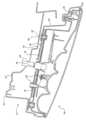
도 9는, 본 발명에 따라, 피봇, 로케이터, 및 전기 커넥터 및 램프 부착 피처를 포함하는 리프트 게이트 조립체의 합치 표면의 사시도이고;
도 10은, 본 발명에 따라, 합치 표면 및 후방 램프 아플리케 조립체를 갖는 리프트 게이트 조립체의 분해 사시도이며;
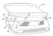
도 11은, 본 발명에 따라, 합치 표면을 도시하는 리프트 게이트 조립체에 연결하도록 피봇하는 후방 램프 아플리케 조립체의 사시도이다.The present invention will be more fully understood from the detailed description and accompanying drawings,
1 is a cross-sectional view of a conventional rear lamp applique assembly connected to a lift gate assembly;
Figure 2 is a cross-sectional view of a rear lamp applique assembly connected to a lift gate assembly in accordance with the present invention;
Figure 3 is a cross-sectional view of the rear lamp applique assembly of Figure 2 bonded to a lift gate assembly, in accordance with the present invention;
Figure 4 is a perspective view of the rear lamp applique assembly of Figures 2 and 3 bonded to a lift gate assembly, in accordance with the present invention;
Figure 5 is a cross-sectional view of a rear lamp applique assembly connected to a lift gate assembly, in accordance with the present invention;
Figure 6 is a cross-sectional view of a rear lamp applique assembly connected to a lift gate assembly, in accordance with the present invention;
Figure 7 is a cross-sectional view of a rear lamp applique assembly connected to a lift gate assembly, in accordance with the present invention;
Figure 8 is a cross-sectional view of a rear lamp applique assembly connected to a lift gate assembly, in accordance with the present invention;
Figure 9 is a perspective view of a mating surface of a lift gate assembly including pivots, locators, and electrical connectors and lamp attachment features, in accordance with the present invention;
Figure 10 is an exploded perspective view of a lift gate assembly with mating surfaces and a rear lamp applique assembly, in accordance with the present invention;
Figure 11 is a perspective view of a rear lamp appliqué assembly pivoting to connect to a lift gate assembly showing a mating surface, in accordance with the present invention.
바람직한 실시예(들)에 대한 다음의 설명은 사실상 단지 예시일 뿐이며 본 발명, 그 적용 또는 사용을 제한하려는 의도는 없다.The following description of the preferred embodiment(s) is merely illustrative in nature and is not intended to limit the invention, its application or use.
도 1은 내부 패널(14) 및 외부 패널(16)을 포함하는, 전체적으로 12로 도시된, 리프트 게이트 조립체에 부착된, 전체적으로 10으로 도시된 종래의 후방 램프 아플리케 조립체를 도시한다. 조립체(10)는 복수의 나사형 부착물(18), 클립(18), 기준 핀(20), 및 접착제 부착 폼 밀봉 개스킷(22)(더 많거나 더 적은 다른 위치가 존재할 수 있음이 이해됨)을 가지며, 이는 또한 불리하게는 본 발명보다 전체 깊이를 더 깊게 만들고 커넥터(26) 접근을 위한 접근 영역(24) 또는 개구를 필요로 하여, 리프트 게이트 조립체(12)의 강성을 감소시킨다.1 shows a conventional rear lamp applique assembly, generally shown at 10, including an inner panel 14 and an
램프 조립체는 일반적으로 D-필러의 경로 및 후방 리프트 게이트 래치로 이어지는 리프트 게이트에 대한 강도에서 벗어난다. 부착을 위한 접근 영역은 또한 강성을 감소시킨다. 종래의 램프는 커넥터에 접근할 수 있도록 접근 패널을 필요로 하며 이는 리프트 게이트의 중요한 구조 영역이다. OEM은 일반적으로 리프트 게이트의 미리 결정된 강성 요건을 필요로 한다. 전체적으로 도 2 내지 도 11을 참조하면, 램프 조립체의 깊이를 최소화하고 램프 부착물을 위한 영역을 여전히 제공하는 것이 바람직하다. 게다가, 본 발명은 리프트 게이트에 대한 위치로 램프의 조립으로 행해진 커넥터의 능동 연결을 허용한다.The lamp assembly is typically out of the way of the D-pillar and into the lift gate leading to the rear lift gate latch. Access areas for attachment also reduce rigidity. Conventional ramps require an access panel to access the connector, which is a critical structural area of the lift gate. OEMs typically require predetermined stiffness requirements for the lift gate. Referring to Figures 2-11 overall, it is desirable to minimize the depth of the lamp assembly and still provide area for lamp attachment. Additionally, the present invention allows for active connection of the connectors performed upon assembly of the lamp into position relative to the lift gate.
바람직하게는, 내부 패널은 사출 성형되고 외부 패널에 접합, 예를 들어 접착제에 의해 접합된다. 외부 패널은 조립 중에 전기 커넥터를 찾거나 위치 결정해야 한다. 적외선 용접과 초음파 용접은 도포하는 데에 마스킹을 필요로 한다. 통상적으로, 외부 패널은 폴리카보네이트이다. 바람직하게는, 리프트 게이트는 복합 리프트 게이트이다.Preferably, the inner panel is injection molded and bonded to the outer panel, for example by adhesive. Exterior panels require locating or locating electrical connectors during assembly. Infrared welding and ultrasonic welding require masking for application. Typically, the exterior panels are polycarbonate. Preferably, the lift gate is a composite lift gate.
이제, 전체적으로 도 2 내지 도 5를, 보다 구체적으로 전체적으로 도 2 내지 도 5를 참조하면, 본 발명은 적어도 하나의 접착제 접합 표면을 갖는 후방 램프 아플리케 하우징을 제공하고, 적어도 하나의 접착제 접합 트랙, 및 적어도 하나의 정합 접착제 접합을 갖는 후방 리프트 게이트 외부 패널을 제공한다. 본 발명은 추가된 체결구, 로케이터 핀 및 밀봉 개스킷을 제거한다. 내부 패널(114) 및 외부 패널(116)을 포함하는, 전체적으로 112로 도시된, 리프트 게이트 조립체에 부착된, 본 발명에 따라 전체적으로 110으로 도시된 후방 램프 아플리케 조립체가 제공된다. 후방 램프 아플리케 조립체(110)는, 예를 들어 118로 표시된 접착제에 의해 리프트 게이트 외부 패널(116)에 접착식으로 접합된다. 후방 램프 아플리케 조립체(110)의 접착제 접합은 'P'로 표시된 접합 경로의 주변 내에 부착 및 수밀식 밀봉을 제공한다.Referring now to FIGS. 2-5 generally, and more specifically to FIGS. 2-5 generally, the present invention provides a rear lamp applique housing having at least one adhesive bonding surface, at least one adhesive bonding track, and A rear lift gate exterior panel is provided having at least one mating adhesive bond. The present invention eliminates added fasteners, locator pins and sealing gaskets. A rear lamp applique assembly, generally shown at 110, is provided in accordance with the present invention, including an
후방 램프 아플리케 조립체(110)는 또한 바람직하게는 리프트 게이트 조립체(112)에 대한 끼워맞춤을 최적화하기 위해, 전체적으로 120으로 표시된, 포켓 내에 위치 설정된다. 가장 바람직하게는, 후방 램프 아플리케 조립체(110)는 리프트 게이트 조립체(112)에 대한 끼워맞춤을 최적화하기 위해 로봇식으로 포켓(120) 내에 위치 설정된다. 일반적으로, 깊이('d'로 표시됨)는 외부 패널(116) 표면 또는 내부 패널(114) 표면, 예를 들어 A-표면, 또는 조립체(110) 표면으로부터 최소화되어 구조적 내부 패널(114)에 대한 최대 단면 깊이(예를 들어, 보다 구체적으로는, 전체적으로 128로 도시된 리프트 게이트 내부 채널의 전체적으로 'S'로 표시된 최대화된 섹션 특성)를 허용한다(예를 들어, 깊이는 50 mm 미만, 통상적으로 약 10 내지 40 mm, 바람직하게는 18 내지 30 mm, 보다 바람직하게는 20 내지 28 mm, 가장 바람직하게는 약 25.0 mm로 최소화되고; 예를 들어, 단면은 50 mm 미만, 통상적으로 약 10 내지 40 mm, 바람직하게는 18 내지 30 mm, 보다 바람직하게는 20 내지 28 mm, 가장 바람직하게는 약 25.0 mm로 최소화됨). 통상적으로, 깊이('d'로 표시됨)는 램프 렌즈(111)의 조립체(110) 외부 표면(110a), 예를 들어 A-표면으로부터 최소화되어 구조적 내부 패널(114)에 대한 최대 단면 깊이를 허용한다(비제한적인 예로서, 일반적으로, 깊이는 30 인치 미만, 통상적으로 약 3 내지 25 인치, 바람직하게는 4 내지 12 인치, 보다 바람직하게는 10 인치 미만, 가장 바람직하게는 8 인치 이하로 최소화됨). 바람직하게는, 깊이 'd'는 A-표면으로부터 약 25.0 mm로 최소화되어 구조적 내부 패널(114)에 대한 최대 단면 깊이를 허용한다.Rear
와이어 하네스(124)는 전체적으로 126으로 표시된 커넥터에서 램프 조립체(110)에 작동 가능하게 연결된다. 대안적으로, 커넥터(126)는 측방향 커넥터이다. 일반적으로, 후방 램프 조립체(110)는 전체적으로 130으로 표시된 적어도 하나의 적절한 미리 결정된 광원을 갖는다. 바람직하게는, 후방 램프 조립체(110)는 발광 다이오드(light emitting diode)(LED) 램프 조립체이다. 적어도 하나의 반사기(134)는, 바람직하게는 복수의 체결구(122)에 의해, 전체적으로 132로 표시된 적어도 하나의 램프 하우징에 작동 가능하게 연결된다. 리프트 게이트 외부 패널(116)은 램프 하우징(132) 및 리프트 게이트 내부 패널(114)에 작동 가능하게 접합된다.
이제, 보다 구체적으로 도 4를 참조하면, 밀봉된 후방 램프 조립체(110)를 조립체(110) 하우징(132)의 주변 둘레의 리프트 게이트 외부 패널(116)에 접착식으로 접합(118)하면 추가적인 다수의 체결구에 대한 필요성이 제거되고 접합부 내의 영역이 효과적으로 방수된다 - 이에 의해, 개스킷의 필요성이 또한 제거된다.Now, referring more specifically to FIG. 4 , adhesively bonding 118 the sealed
보다 구체적으로 도 5를 참조하면, 전체적으로 210으로 도시된 후방 램프 아플리케 조립체는 전체적으로 212로 표시된 리프트 게이트 조립체에 연결되어, 전체적으로 230으로 도시된 측방향 커넥터와 함께 극단적인 수축 랩 배열을 제공한다. 조립체(210)는 내부 패널(214)에 결합되고 외부 패널(216)에 연결된다. 램프 하우징(220)은 외부 패널(216)에 접합(218), 가장 바람직하게는 접착제 접합된다. 외부 패널(216)은 또한 내부 패널(214)에 연결되며, 예를 들어 접착제, 적외선 용접, 초음파 등, 가장 바람직하게는 접착제(218)로 접합된다. 적어도 하나의 반사기(222)는 램프 하우징(220)에 연결되며, 바람직하게는 복수의 체결구(224)에 의해 고정된다. 접착제(218)는 물 갇힘을 제거하는 데에 도움이 된다.Referring more specifically to Figure 5, the rear lamp appliqué assembly, generally shown at 210, is connected to the lift gate assembly, generally shown at 212, to provide an extreme shrink wrap arrangement with lateral connectors generally shown at 230.
대안적으로, 작동 가능한 밀봉 피처, 예를 들어, 멈춤쇠 링, 통합형 시일을 갖는 멈춤쇠 링, 경사진 링, 적절한 선택적으로 해제 가능한 멈춤쇠 피처 등이 자체 밀봉 커넥터(230)에 제공되어 커넥터(230)를 외부 패널(216)에 연결하고 밀봉하여 외부 패널(216) 및 커넥터(430)가 이동에 영향을 미친다.Alternatively, an actuable sealing feature, e.g., a detent ring, a detent ring with an integrated seal, a beveled ring, a suitable selectively releasable detent feature, etc., may be provided in the self-sealing
내부 패널(214) 웹과 커버(예를 들어, 램프 렌즈 커버(232) 또는 하우징(222)) 사이에 형성된 포켓 내의 리프트 게이트의 절단선 에지에 있는 반사기 - 전체적으로 226으로 또한 표시됨 - 가 핀치 방지 센서(234) 장착 표면을 연장시켜 세정 에지를 제공한다. 확장된 APS 장착은 램프 조립체(210)의 에지를 보호하여 보다 공격적인 조명 대 에지 상태를 허용한다. 예로서, 내부 패널(214)은 하우징(222)의 외향 에지 영역에 인접하게 돌출한다. 또한, 전체적으로 228로 표시된 바와 같이, 내부 패널 웹 높이는 일반적으로 반사기(222)(예를 들어, 전체적으로 222a 및 222b로 표시된 반사기 부분) 사이의 또는 반사기에 인접한 램프 비기능 체적으로 현재 설계에 비해 약 100% 증가를 위해 침입함으로써 강성을 위해 최대화된다. 일반적으로, D-필러로부터 약 50 mil을 꺼낸다. 또한, 전체적으로 230으로 표시된, 대체로 X-Z 평면(와이어 하네스(236)의 경우)에서 리프트 게이트 아플리케 램프 커넥터 배향은 측방향 연결 및 팁인(tip in)이 램프 조립체(210)를 리프트 게이트 조립체(212)에 접합/결합하는 동안 연결되게 한다. 리프트 게이트 측면 커넥터(230) 및 워터 시일은 외부 및 내부 패널에 형성된 피처(예를 들어, 접착제 접합부(218)) 상에 위치된다. 커넥터(230), 바람직하게는 측방향 커넥터는 임의의 손 접근 구멍을 제거하고 내부 패널(214) 및 공간을 더욱 최적화한다. 대안적으로, 커넥터(230)는 리프트 게이트 또는 "D-링"의 플랜지 영역 내에 있다. 대안적으로, 커넥터가 외부 패널 또는 내부 패널에 통합되는 통합형 커넥터 설계가 아래에서 더 상세하게 설명된다.A reflector at the cutline edge of the lift gate in a pocket formed between the
구조적 내부 패널(214)에 대한, 전체적으로 240으로 도시된 리프트 게이트 내부 채널의 단면 특성은 화살표 'S'로 전체적으로 표시된 용례에 따라 미리 결정된 양으로 최대화된다(예를 들어, 깊이는 50 mm 미만, 통상적으로 약 10 내지 40 mm, 바람직하게는 18 내지 30 mm, 보다 바람직하게는 20 내지 28 mm, 가장 바람직하게는 약 25.0 mm로 최소화되고; 예를 들어, 단면은 50 mm 미만, 통상적으로 약 10 내지 40 mm, 바람직하게는 18 내지 30 mm, 보다 바람직하게는 20 내지 28 mm, 가장 바람직하게는 약 25.0 mm로 최소화됨).For structural
도 5는 램프 조립체(210)의 하우징(222)의 길이를 통해 'L'로 표시된 길이방향 라인을 도시한다. 전기 커넥터(230)는 용례에 따라 길이방향 라인 'L'로부터 미리 결정된 거리에 있는 미리 결정된 영역에 위치된다. 일반적으로, 커넥터(230)는 길이방향 라인의 단부 중 하나로부터 임의의 거리로 정의되는 영역에 이상적으로 위치된다. 통상적으로, 거리는 길이방향 라인 길이의 백분율, 바람직하게는 라인의 단부 중 하나에서 약 15% 내지 50%, 보다 바람직하게는 라인의 단부 중 하나에서 약 20% 내지 40%, 가장 바람직하게는 라인의 단부 중 하나에서 약 30%이다. 라인 'L'이 아무리 길어도, 단부로부터 거리의 미리 결정된 백분율, 예를 들어 약 30%에서, 커넥터는 선형 방식으로 커넥터의 다른 단부와 접촉하지 않을 것이다.Figure 5 shows a longitudinal line marked 'L' through the length of the
대안적으로, 내부 패널(214)은 미리 결정된 위치 또는 평면, 예를 들어 상부 길이방향 평면에서 등각 표면을 갖는다. 로우 프로파일 등각 램프와 등각 표면 및 재료가 대응하여 D-필러의 강성을 더 크게 만든다. 기하형상과 재료를 고려한다. 바람직하게는, "I"는 미리 결정된 높이, 가장 바람직하게는 내부 패널 및 리프트 게이트의 내부 영역과 같은 기하형상이다. 바람직하게는, "E"는 미리 결정된 재료, 예를 들어 조성물의 강성이다. 예를 들어, 수학식 I = bh3/12(예를 들어, b = 폭이고 h = 높이). 바람직하게는, "I"는 20% 이상이다. D-필러 강성에 관하여, 통상적으로, 필러는 내부 패널(214) 및 라이트 하우징(222) 상의 미리 결정된 등각 표면으로 인해 두껍게 유지되는데, 이는 라이트 하우징(222)이 더 얕은 깊이를 가질 수 있게 한다. 일반적으로, 강성 강도는 깊이에 대해 입방 관계(cubic relationship)이다.Alternatively, the
일반적으로, 후방 램프 조립체(210)는 전체적으로 238로 표시된 적어도 하나의 적절한 미리 결정된 광원을 갖는다. 바람직하게는, 후방 램프 조립체(210)는 발광 다이오드(LED) 램프 조립체이다. 적어도 하나의 반사기(222)는, 바람직하게는 복수의 체결구(224)에 의해 적어도 하나의 램프 하우징(220)에 작동 가능하게 연결된다. 리프트 게이트 외부 패널(216)은 램프 하우징(220) 및 리프트 게이트 내부 패널(214)에 작동 가능하게 접합된다.Generally,
하우징(222)은 일반적으로 형태가 아치형일 수 있다. 본 발명의 범위를 벗어나지 않고 용례에 따라 다른 형상이 고려된다. 아치형 형태 및 진입 문제는 램프 하우징(222) 상의 리드 인과 같은 조종 피처에 의해 해결되어 정확한 지점으로 조종한다.
전체적으로 도 2 내지 도 5를 다시 참조하면, 본 발명은 치수 제어 및 부착 무결성을 유지하면서 램프 부착 시스템의 패키지 깊이를 감소시킨다. 또한, 접합 영역 내에서 리프트 게이트 폐쇄를 위한 수밀식 시일을 제공하는 역할을 한다. 종래의 램프 서브 조립체 자체는, 리프트 게이트에 대한 최종 램프 조립체와 함께, 다수의 구입 체결구가 필요로 고; 반면에, 본 발명의 일체로 접합된 설계는 다수의 체결구를 조립하는 데에 드는 비용, 질량 및 노동력을 제거한다. 게다가, 종래의 램프 서브 조립체 자체는, 리프트 게이트에 대한 최종 조립체와 함께, 램프 내에 그리고 리프트 게이트 폐쇄에 대한 수밀식 밀봉을 유지하기 위해 다수의 밀봉 개스킷을 필요로 하고; 반면에, 본 발명의 일체로 접합된 설계는 다수의 개스킷을 조립하는 데에 드는 비용, 질량 및 노동력을 제거한다.Referring again to Figures 2-5 overall, the present invention reduces the package depth of a lamp attachment system while maintaining dimensional control and attachment integrity. It also serves to provide a watertight seal for lift gate closure within the joint area. The conventional ramp sub-assembly itself, along with the final ramp assembly to the lift gate, requires multiple off-the-shelf fasteners; On the other hand, the integrally bonded design of the present invention eliminates the cost, mass and labor of assembling multiple fasteners. Additionally, the conventional ramp subassembly itself, along with the final assembly to the lift gate, requires multiple sealing gaskets to maintain a watertight seal within the ramp and to the lift gate closure; On the other hand, the integrally bonded design of the present invention eliminates the cost, mass and labor of assembling multiple gaskets.
더욱이, 본 발명에 따른 접착제 접합 부착 방법은, 필요한 구성요소 보유 뿐만 아니라 램프 구성요소 및 리프트 게이트 조립체를 위한 수밀식 밀봉을 제공하면서, 치수 무결성을 유지하기 위해 로봇식으로 제어된다.Moreover, the adhesive bond attachment method according to the present invention is robotically controlled to maintain dimensional integrity while providing a watertight seal for the ramp components and lift gate assembly as well as retaining the necessary components.
앞서 언급한 임의의 설명은 측방향 연결에 적응 가능하다. 크로스 카를 직접 스냅하는 측방향 연결이 본 발명에서 벗어나지 않고 고려된다. 스냅이 있거나 없는 측방향 연결이 본 발명에서 벗어나지 않고 고려된다. 짐수레에 대한 접착제 시간을 위한 자체 고정 클립이 본 발명에서 벗어나지 않고 고려된다. 스냅을 포함하거나 스냅을 사용하여 고정하는 동안 접착제 세트가 본 발명에서 벗어나지 않고 고려된다. 리빙 힌지는 본 발명에서 벗어나지 않고 고려된다. 피봇 요동 피처가 본 발명에서 벗어나지 않고 고려된다. 램프의 위치 설정을 제어하기 위한 안내 피처가 본 발명에서 벗어나지 않고 고려된다. 용례에 따른 다양한 로케이터 핀 옵션이 본 발명에서 벗어나지 않고 고려된다. 장착 위치로 조종하기 위한 램프 하우징 상의 리드가 본 발명에서 벗어나지 않고 고려된다. 접근의 용이성 및 정확성, 예를 들어 램프 연결을 위한 미리 결정된 각도가 본 발명에서 벗어나지 않고 고려된다. 외부로부터 안으로 램프를 피봇시키는 것이 본 발명에서 벗어나지 않고 고려된다. 내부로부터 밖으로 램프 피봇시키는 것이 본 발명에서 벗어나지 않고 고려된다. 측방향으로의 램프 직진성이 본 발명에서 벗어나지 않고 고려된다. 램프 랩 오버 탑(lamp wrap over top)이 본 발명에서 벗어나지 않고 고려된다. 램프 업/다운이 본 발명에서 벗어나지 않고 고려된다. 가장 바람직하게는, 전기 커넥터는 외부 패널에 있고 밀봉 수단이 외부 패널에 있다. 바람직하게는, 안내 및 부유가 제공된다. 바람직하게는, 서비스 가용성을 위한 멈춤쇠가 제공된다.Any of the previously mentioned descriptions are adaptable to lateral connections. A lateral connection that directly snaps the cross car is contemplated without departing from the invention. Lateral connections with or without snaps are contemplated without departing from the invention. Self-securing clips for gluing times to carts are contemplated without departing from the present invention. Adhesive sets that include snaps or are fastened using snaps are contemplated without departing from the present invention. Living hinges are contemplated without departing from the present invention. Pivot rocking features are considered without departing from the present invention. Guidance features for controlling the positioning of the lamp are contemplated without departing from the invention. Various locator pin options depending on application are contemplated without departing from the present invention. A lid on the lamp housing for maneuvering into the mounting position is contemplated without departing from the invention. Ease of access and accuracy, for example predetermined angles for lamp connection, are taken into account without departing from the invention. Pivoting the ramp from the outside in is contemplated without departing from the invention. Pivoting the ramp from the inside out is contemplated without departing from the present invention. Ramp straightness in the lateral direction is considered without departing from the invention. A lamp wrap over top is contemplated without departing from the present invention. Ramp up/down is contemplated without departing from the present invention. Most preferably, the electrical connector is on the outer panel and the sealing means is on the outer panel. Preferably, guidance and flotation are provided. Preferably, a detent for serviceability is provided.
리프트 게이트 외부 패널에 접합된, 예를 들어, 바람직하게는 접착제 접합된 후방 램프 아플리케 조립체(110, 210)는 다음을 포함하지만 이에 제한되지 않는 많은 이점을 갖는다: 기계식 체결구에 필요한 깊이를 제거하여 F/A 패키지 공간을 최소화하고; 기준 핀에 필요한 깊이를 제거하여 F/A 패키지 공간을 최소화하며; 밀봉된 기계식 체결구의 부품 비용을 제거하고; 기계식 체결구에 접근할 필요성을 제거하며; 체결구 설치를 위한 조립 비용을 제거하고; 전기 커넥터에서 개스킷의 부품 비용을 제거하며; 체결구의 질량을 제거하고; LED 기술은 서비스 필요성을 최소화하며; 서비스는 백라이트 교체에 단순할 수 있고; 램프는 모듈에 PIA를 전달하며; 접착제 부착은 백열 전구 실행을 방지하지 않는다 - 하지만 바람직하지 않음.Rear
상기 도 2 내지 도 5 중 어느 하나에서, 바람직하게는 커넥터의 하우징은 공차를 위해 미리 결정된 양의 커넥터 이동을 허용한다. 바람직하게는, 통합형 램프 연결부는 미리 결정된 공차를 수용하도록 미리 결정된 양만큼 부유한다. 대안적으로, 통합형 램프 연결부는 부유하지 않는다.2-5 above, preferably the housing of the connector allows a predetermined amount of connector movement for tolerance purposes. Preferably, the integrated ramp connection floats a predetermined amount to accommodate the predetermined tolerance. Alternatively, the integrated lamp connection does not float.
이제, 도 6 내지 도 10을 참조하면, 일반적으로, 접착제 또는 체결구에 대한 필요성이 없는 부착된 램프, 예를 들어 완전 스냅 끼워맞춤 부착된 램프가 제공된다. 게다가, 리프트 게이트에 대한 자체 결합 전기 램프 전기 커넥터가 제공된다.Referring now to Figures 6-10, generally, an attached lamp is provided without the need for adhesives or fasteners, for example a full snap fit attached lamp. Additionally, self-associating electric lamp electrical connectors for the lift gate are provided.
이제, 도 6을 참조하면, 일반적으로, 접착제 또는 체결구에 대한 필요성이 없는 완전히 스냅 부착된 램프의 예시적인 부착이 예시되어 있다. 게다가, 리프트 게이트에 대한 자체 결합 전기 램프 전기 커넥터가 제공된다. 손 접근 구멍이 없다. 느슨한 와이어 하네스를 램프에 연결하기 위한 손 접근 구멍이 필요하지 않는데, 이는 상당한 이점이다.Referring now to Figure 6, an exemplary attachment of a fully snap attached lamp is illustrated, generally without the need for adhesives or fasteners. Additionally, self-associating electric lamp electrical connectors for the lift gate are provided. There is no hand access hole. There is no need for a hand access hole to attach a loose wire harness to the lamp, which is a significant advantage.
후방 램프 아플리케 조립체, 예를 들어 적어도 내부 패널(314) 및 외부 패널(316)을 포함하는, 전체적으로 312로 도시된 리프트 게이트 조립체에 부착된, 본 발명에 따라 전체적으로 310으로 도시된 리프트 게이트 아플리케 램프가 제공된다. 외부 패널(316)은 바람직하게는 내부 패널(314)에 접착제 접합(318)되어 접착제 조인트를 생성한다. 조립체(310)는 바람직하게는 작동 가능하게 협력하는 끼워맞춤 피처에 의해, 가장 바람직하게는 스냅 끼워맞춤에 의해 리프트 게이트 외부 패널(316)에 작동 가능하게 부착된다.A lift gate applique lamp, shown generally at 310, is attached to a rear lamp applique assembly, e.g., a lift gate assembly, shown generally at 312, comprising at least an
전체적으로 350으로 도시된 적어도 하나의 자체 밀봉 커넥터, 가장 바람직하게는 와이어 하네스(351)를 위한 자체 밀봉 1/4 턴 와이어 하네스 커넥터(350)가 제공된다. 각각의 자체 밀봉 커넥터(350)는 전체적으로 352로 표시된 통합형 램프 연결부, 바람직하게는 공차를 위해 미리 결정된 양의 커넥터 이동을 허용하는 하우징을 수용한다. 바람직하게는, 커넥터(350) 및/또는 통합형 램프 연결부(352)는 부유한다. 대안적으로, 350 및/또는 통합형 램프 연결부는 부유하지 않는다. 이는 접근 개구를 필요로 하지 않으며, 이에 의해 물의 침입을 더 최소화하는데, 이는 상당한 이점이다. 자체 밀봉 커넥터(350)는 바람직하게는 별도의 부품이고 인터페이스는 외부 패널(316)에 몰딩된다.At least one self-sealing connector, generally shown at 350, is provided, most preferably a self-sealing quarter turn
자체 밀봉 커넥터(350)의 작동 가능한 밀봉 피처(392), 예를 들어 멈춤쇠 링, 경사진 링, 통합형 시일이 있는 멈춤쇠 링 등은 커넥터(350)를 외부 패널(316)에 연결하고 밀봉하여 내부 패널(314)이 아닌 외부 패널(316) 및 커넥터(350)가 이동, 예를 들어 미리 결정된 부유에 영향을 미친다.Operable sealing features 392 of the self-sealing
밀봉 피처(392)는 차량이 도로를 주행하는 동안 커넥터(350)의 움직임을 방지하고 워터 시일을 허용한다. 서비스 가용성을 허용하는 라인 힌지 또는 다른 적절한 피처가 있는 스프링 로딩형 멈춤쇠가 바람직하다. 바람직하게는, 결합 기능이 수행될 수 있지만, 충분한 저항이 멈춤쇠를 극복할 수 있다. 예를 들어, 핀이 사용되어 구멍을 통해 밀어 내고 서비스 가용성을 위해 멈춤쇠를 해제하는 것이 본 발명에서 벗어나지 않고 고려된다.
전체적으로 354로 도시된 적어도 하나의 통합형 스냅 부착 피처, 보다 바람직하게는 복수의 통합형 스냅 부착 피처(354)가 추가로 제공된다. 적어도 하나의 통합형 스냅 부착 피처(354)는 후방 램프 아플리케 조립체(310)를 리프트 게이트 외부 패널(316)에 연결하도록 작동 가능하게 위치된다. 따라서, 추가 접합, 접착제 또는 체결구가 필요하지 않다. 외부 패널(316) 상에 제공되거나 외부 패널과 일체로 형성된 적어도 하나의 제1 대응 수용 피처(358)(예를 들어, 구멍, 립, 레지 또는 제1 스냅 피처(354a)를 수용하고 유지하기 위한 다른 적절한 대응 구조)에 작동 가능하게 끼워지는 적어도 하나의 제1 통합형 스냅 피처(354a)가 램프 조립체(310) 상에(예를 들어, 조립체(310)의 하우징(356) 상에)에 제공된다. 보다 바람직하게는, 제1 부착 피처(354a)는 각각 적어도 하나의 구멍(358)을 통해 끼워지는 적어도 하나의 핀이다. 가장 바람직하게는, 제1 부착 피처(354a)는 설치된 차량 위치에 대해 조립체(310)의 외부 단부를 향해 각각 적어도 하나의 구멍(358)을 통해 끼워지는 적어도 하나의 핀이다. 대안적으로는, 설치된 차량 위치에 대해 조립체(310)의 내부 단부. 바람직하게는, 통합형 스냅 피처(354a)는 전체적으로 394로 표시된 지지점 영역에 인접하여 조립체 피봇 위치를 제공한다. 본 발명의 범위를 벗어나지 않고 용례에 따라 접합 없이 부착하기에 적절한 다른 피처가 고려된다. 외부 패널(316) 상에 제공되거나 외부 패널과 일체로 형성된, 전체적으로 362로 표시된 적어도 하나의 제2 대응 수용 피처(예를 들어, 구멍, 립, 레지 또는 제2 스냅 피처(354b)를 수용하고 유지하기 위한 다른 적절한 대응 구조)에 작동 가능하게 끼워지는, 전체적으로 354b로 도시된 적어도 하나의 제2 스냅 피처가 램프 조립체(310) 상에 제공된다(예를 들어, 하우징(356) 상에 형성된다). 바람직하게는, 제2 부착 피처(354b)는, 바람직하게는 예를 들어 세장형의 대체로 수직으로 연장하는 클립, 레지, 플랜지인 조립체(310)의 외부 에지의 선단 에지를 따라 대체로 수직으로 연장되는 대응 구조에 작동 가능하게 스냅 끼워맞춤되는 적어도 하나의 클립, 레지, 플랜지, 미늘 및/또는 후크이다. 가장 바람직하게는, 제2 스냅 피처는 램프 스냅 후크이다.At least one integrated snap attachment feature, more preferably a plurality of integrated snap attachment features 354, generally shown at 354, is further provided. At least one integrated
리프트 게이트 아플리케 램프 조립체(310)와 리프트 게이트 외부 패널(316) 사이의 복수의 통합형 스냅 부착 피처(354)는 램프 조립체(310)를 외부 패널(316)에 부착하기 위한 추가 접합 및 체결구의 필요성을 제거한다. 외부 패널(316)은, 예를 들어 접착제에 의해 내부 패널(314)에 접합된다.A plurality of integrated snap attachment features 354 between the lift gate
적어도 하나의 로케이터 핀(388)이 램프 조립체(310), 가장 바람직하게는 하우징(356)에 제공되어, 외부 패널(316)에 형성된 리세스 또는 구멍(390)에 정렬되어 외부 패널(316)에 대해 램프 조립체(310)를 정렬하는 것을 돕는다.At least one
조립체(310)는 또한 바람직하게는 리프트 게이트 조립체(312)에 대한 끼워맞춤을 최적화하고 깊이(전체적으로 'd'로 표시됨)를 최소화하기 위해 전체적으로 320으로 표시된 외부 패널의 316 포켓 내에 위치 설정된다. 예시적인 실시예에서, 깊이는 약 45 mm, 통상적으로 약 10 내지 45 mm, 바람직하게는 약 10 내지 30 mm, 보다 바람직하게는 약 10 내지 25.0 mm로 최소화된다.
예시적인 실시예에서, 램프를 연결하는 데에 사용되는 접착제가 없다.In the exemplary embodiment, there is no adhesive used to connect the lamps.
와이어 커넥터(350)는 복수의 와이어 점퍼(366), 및 내부 패널(314)의 전체적으로 370으로 표시된 리프트 게이트 내부 채널 영역 내의 와이어 하네스(368)에 작동 가능하게 연결된다.
후방 램프 조립체(310)는 적어도 하나의 적절한 미리 결정된 광원(364)을 갖는다. 바람직하게는, 후방 램프 조립체(310)는 발광 다이오드(LED) 램프 조립체이다. 적어도 하나의 반사기(372)는 바람직하게는 복수의 체결구(374)에 의해 하우징(356)에 연결된다. 복수의 광원(364)은 제1 인쇄 회로 기판(376), 예를 들어 LED 인쇄 회로 기판에 작동 가능하게 연결된다. 적어도 하나의 확산기 베젤(378)은 일반적으로 인쇄 회로 기판(376)과 램프 렌즈(380) 사이에 위치된다. 제2 인쇄 회로 기판(382), 예를 들어 LED 인쇄 회로 기판은 적어도 하나의 와이어 점퍼(366) 부착물(366a) 및 제1 광 파이프 부분(384)에 작동 가능하게 연결된다. 제3 인쇄 회로 기판(386), 예를 들어 LED 인쇄 회로 기판은 적어도 하나의 와이어 점퍼(366) 부착물(366b) 및 제2 광 파이프 부분(386)에 작동 가능하게 연결된다.
부착물은 바람직하게는 피봇 연결 영역을 형성한다. 와이어 하네스 커넥터(350)는 용례에 따라 미리 결정된 작동 가능한 위치에 위치된다. 예로서, 램프 조립체의 하우징(356)의 길이방향 길이를 취하면, 전기 커넥터(350)는 용례에 따라 하우징(356)을 통해 길이방향 축으로부터 미리 결정된 거리에 있는 미리 결정된 영역에 위치된다. 일반적으로, 커넥터(350)는 길이방향 라인의 단부 중 하나로부터 임의의 거리로 정의되는 영역에 이상적으로 위치된다. 통상적으로, 거리는 길이방향 라인 길이의 백분율, 바람직하게는 라인의 단부 중 하나에서 약 15% 내지 50%, 보다 바람직하게는 라인의 단부 중 하나에서 약 20% 내지 40%, 가장 바람직하게는 라인의 단부 중 하나에서 약 30%이다. 라인 'L'이 아무리 길어도, 단부로부터 거리의 미리 결정된 백분율, 예를 들어 약 30%에서, 커넥터는 선형 방식으로 커넥터의 다른 단부와 접촉하지 않을 것이다.The attachment preferably forms a pivot connection area. The
대안적으로, 내부 패널(312)은 미리 결정된 위치 또는 평면, 예를 들어 상부 길이방향 평면에서 등각 표면을 갖는다. 로우 프로파일 등각 램프와 등각 표면 및 재료가 대응하여 D-필러의 강성을 더 크게 만든다. 기하형상과 재료를 고려한다. 바람직하게는, "I"는 미리 결정된 높이, 가장 바람직하게는 내부 패널 및 리프트 게이트의 내부 영역과 같은 기하형상이다. 바람직하게는, "E"는 미리 결정된 재료, 예를 들어 조성물의 강성이다. 예를 들어, 수학식 I = bh3/12(예를 들어, b = 폭이고 h = 높이). 바람직하게는, "I"는 20% 이상이다. D-필러 강성에 관하여, 통상적으로, 필러는 내부 패널(314) 및 라이트 하우징(356) 상의 미리 결정된 등각 표면으로 인해 두껍게 유지되는데, 이는 라이트 하우징(356)이 더 얕은 깊이를 가질 수 있게 한다. 일반적으로, 강성 강도는 깊이에 대해 입방 관계이다.Alternatively, the
이제, 도 7을 참조하면, 일반적으로, 접착제 또는 체결구에 대한 필요성이 없는 완전히 스냅 부착된 램프의 예시적인 부착이 예시되어 있다. 게다가, 리프트 게이트에 대한 자체 결합 전기 램프 전기 커넥터가 제공된다. 느슨한 와이어 하네스를 램프에 연결하기 위한 손 접근 구멍이 없는데, 이는 상당한 이점이다.Referring now to Figure 7, an exemplary attachment of a fully snap attached lamp is illustrated, generally without the need for adhesives or fasteners. Additionally, self-associating electric lamp electrical connectors for the lift gate are provided. There are no hand access holes for attaching a loose wire harness to the lamp, which is a significant advantage.
전체적으로 410으로 도시된 후방 램프 아플리케 조립체, 예를 들어 적어도 내부 패널(414) 및 외부 패널(416)을 포함하는, 전체적으로 412로 도시된 리프트 게이트 조립체에 부착된, 본 발명에 따른 리프트 게이트 아플리케 램프가 제공된다. 외부 패널(416)은 바람직하게는 내부 패널(414)에 접착제 접합(418)된다. 조립체(410)는 바람직하게는 작동 가능하게 협력하는 끼워맞춤 피처에 의해, 가장 바람직하게는 적어도 하나의 스냅 끼워맞춤 배열에 의해 리프트 게이트 외부 패널(416)에 작동 가능하게 부착된다.A lift gate applique lamp according to the present invention attached to a rear lamp appliqué assembly, generally shown at 410, e.g., a lift gate assembly, generally shown at 412, comprising at least an
전체적으로 420으로 도시된 적어도 하나의 밀봉된 커넥터, 예를 들어 자체 밀봉 커넥터, 가장 바람직하게는 와이어 하네스(421)를 위한 자체 밀봉 1/4 턴 와이어 하네스 커넥터(420)가 제공된다. 자체 밀봉 커넥터(420)는 전체적으로 422로 표시된 통합형 램프 연결부, 바람직하게는 공차를 위해 미리 결정된 양의 커넥터 이동을 허용하는 하우징을 수용한다. 바람직하게는, 통합형 램프 연결부(422)는 부유한다. 대안적으로, 통합형 램프 연결부(422)는 부유하지 않는다. 부착에는 접근 구멍이 필요하지 않으며, 이에 의해 물의 침입을 더 최소화하는데, 이는 상당한 이점이다.At least one sealed connector, generally shown at 420, is provided, for example a self-sealing connector, most preferably a self-sealing quarter turn
자체 밀봉 커넥터(420)의 작동 가능한 밀봉 피처(468), 예를 들어 멈춤쇠 링, 경사진 링, 통합형 시일이 있는 멈춤쇠 링 등은 커넥터(420)를 외부 패널(416)에 연결하고 밀봉하여 내부 패널(414)이 아닌 외부 패널(416) 및 커넥터(420)가 이동, 예를 들어 미리 결정된 부유에 영향을 미친다.Operable sealing features 468 of self-sealing
밀봉 피처(468)는 차량이 도로를 주행하는 동안 커넥터(420)의 움직임을 방지하고 워터 시일을 허용한다. 서비스 가용성을 허용하는 라인 힌지 또는 다른 적절한 피처가 있는 스프링 로딩형 멈춤쇠가 바람직하다. 바람직하게는, 결합 기능이 수행될 수 있지만, 충분한 저항이 멈춤쇠를 극복할 수 있다. 예를 들어, 핀이 사용되어 구멍을 통해 밀어 내고 서비스 가용성을 위해 멈춤쇠를 해제하는 것이 본 발명에서 벗어나지 않고 고려된다. 본 발명의 범위를 벗어나지 않고 용례에 따라 추가적인 적절한 시일이 제공되는 것이 고려된다.
전체적으로 424로 도시된 적어도 하나의 통합형 스냅 부착 피처가 추가로 제공된다. 적어도 하나의 통합형 스냅 부착 피처(424)는 바람직하게는 램프 스냅 후크이다. 바람직하게는, 통합형 스냅 피처의 전체적으로 426으로 표시된 적어도 하나의 제1 절반부가 램프 조립체(410) 상에 제공되고, 가장 바람직하게는 하우징(428) 상에 형성되며, 통합형 스냅 피처의 적어도 하나의 제2 절반부(427)가 리프트 게이트 조립체(412) 상에, 가장 바람직하게는 외부 패널(416) 상에 제공된다.At least one integrated snap attachment feature, generally shown at 424, is further provided. At least one integrated
리프트 게이트 아플리케 램프 조립체(410)와 리프트 게이트 외부 패널(416) 사이의 통합형 스냅 부착 피처(424)는 램프 조립체(410)를 외부 패널(416)에 부착하기 위한 추가 접합 및 체결구의 필요성을 제거한다.Integrated snap attachment features 424 between the lift gate
조립체(410)는 또한 바람직하게는 리프트 게이트 조립체(412)에 대한 끼워맞춤을 최적화하고 깊이(전체적으로 'd'로 표시됨)를 최소화하기 위해 전체적으로 430으로 표시된 외부 패널의 416 포켓 내에 위치 설정된다. 예시적인 실시예에서, 깊이는 약 45 mm, 통상적으로 약 10 내지 45 mm, 바람직하게는 약 10 내지 30 mm, 보다 바람직하게는 약 10 내지 25.0 mm로 최소화된다.
예시적인 실시예에서, 램프를 연결하는 데에 사용되는 접착제가 없다.In the exemplary embodiment, there is no adhesive used to connect the lamps.
와이어 커넥터(420)는 복수의 와이어 점퍼(432), 및 내부 패널(414)의 전체적으로 436으로 표시된 리프트 게이트 내부 채널 영역 내에 제공된 와이어 하네스(434)에 작동 가능하게 연결된다.
후방 램프 조립체(410)는 적어도 하나의 적절한 미리 결정된 광원(438)을 갖는다. 바람직하게는, 후방 램프 조립체(410)는 발광 다이오드(LED) 램프 조립체이다. 적어도 하나의 반사기(440)는 바람직하게는 복수의 체결구(442)에 의해 하우징(428)에 연결된다. 바람직하게는, 최내부 체결구(442)가 일반적으로 조립체 피봇 위치를 제공하는 것으로 표시된 지지점 영역에 인접한다. 복수의 광원(438)은 제1 인쇄 회로 기판(444), 예를 들어 LED 인쇄 회로 기판에 작동 가능하게 연결된다. 적어도 하나의 확산기 베젤(446)은 일반적으로 인쇄 회로 기판(444)과 램프 렌즈(448) 사이에 위치된다. 제2 인쇄 회로 기판(450), 예를 들어 LED 인쇄 회로 기판은 적어도 하나의 와이어 점퍼(432) 부착물(432a) 및 제1 광 파이프 부분(452)에 작동 가능하게 연결된다. 제3 인쇄 회로 기판(454), 예를 들어 LED 인쇄 회로 기판은 적어도 하나의 와이어 점퍼(432) 부착물(432b) 및 제2 광 파이프 부분(456)에 작동 가능하게 연결된다.
복수의 도난 방지 체결구(458)는 램프 조립체(410)를 리프트 게이트 조립체(412)에 연결한다. 바람직하게는, 도난 방지 체결구(458)(예를 들어, M6 도난 방지 나사)는 하우징(428)을 외부 패널(416)에 연결한다.A plurality of
적어도 하나의 램프 베이스 장착 클립(460)이 또한 제공된다. 클립(460)은 외부 패널(416)에 형성된 각각의 구멍(462)을 통해 끼워진다. 적어도 하나의 로케이터 핀(464)이 램프 조립체(410) 상에, 가장 바람직하게는 하우징(428) 상에 제공되어, 외부 패널(416)에 형성된 리세스 또는 구멍에 정렬됨으로써, 외부 패널 및/또는 램프 스냅 후크(424)의 구멍(462) 내에 장착 클립(460)을 맞물리게 하도록 외부 패널(416)에 대해 램프 조립체(410)를 정렬하는 것을 돕는다.At least one lamp
부착물은 바람직하게는 피봇 연결 영역을 형성한다. 와이어 하네스 커넥터(420)는 용례에 따라 미리 결정된 작동 가능한 위치에 위치된다. 도 7은 램프 조립체의 하우징(428)의 길이를 통해 'L'로 표시된 길이방향 라인을 도시한다. 전기 커넥터(420)는 용례에 따라 'L'로부터 미리 결정된 거리에 있는 미리 결정된 영역에 위치된다. 일반적으로, 커넥터(420)는 길이방향 라인의 단부 중 하나로부터 임의의 거리로 정의되는 영역에 이상적으로 위치된다. 통상적으로, 거리는 길이방향 라인 길이의 백분율, 바람직하게는 라인의 단부 중 하나에서 약 15% 내지 50%, 보다 바람직하게는 라인의 단부 중 하나에서 약 20% 내지 40%, 가장 바람직하게는 라인의 단부 중 하나에서 약 30%이다. 라인 'L'이 아무리 길어도, 단부로부터 거리의 미리 결정된 백분율, 예를 들어 약 30%에서, 커넥터는 선형 방식으로 커넥터의 다른 단부와 접촉하지 않을 것이다.The attachment preferably forms a pivot connection area. The
대안적으로, 내부 패널(412)은 미리 결정된 위치 또는 평면, 예를 들어 상부 길이방향 평면에서 등각 표면을 갖는다. 로우 프로파일 등각 램프와 등각 표면 및 재료가 대응하여 D-필러의 강성을 더 크게 만든다. 기하형상과 재료를 고려한다. 바람직하게는, "I"는 미리 결정된 높이, 가장 바람직하게는 내부 패널 및 리프트 게이트의 내부 영역과 같은 기하형상이다. 바람직하게는, "E"는 미리 결정된 재료, 예를 들어 조성물의 강성이다. 예를 들어, 수학식 I = bh3/12(예를 들어, b = 폭이고 h = 높이). 바람직하게는, "I"는 20% 이상이다. D-필러 강성에 관하여, 통상적으로, 필러는 내부 패널(414) 및 라이트 하우징(428) 상의 미리 결정된 등각 표면으로 인해 두껍게 유지되는데, 이는 라이트 하우징(428)이 더 얕은 깊이를 가질 수 있게 한다. 일반적으로, 강성 강도는 깊이에 대해 입방 관계이다.Alternatively, the
이제, 도 8을 참조하면, 일반적으로, 접착제 또는 체결구에 대한 필요성이 없는 완전히 스냅 부착된 램프의 예시적인 부착이 예시되어 있다. 게다가, 리프트 게이트에 대한 자체 결합 전기 램프 전기 커넥터가 제공된다. 느슨한 와이어 하네스를 램프에 연결하기 위한 손 접근 구멍이 없는데, 이는 상당한 이점이다. 램프 조립체(510)는 리프트 게이트 조립체(512)에 연결되고 본 발명에 따라 전체적으로 520으로 도시된 외부 위치 전기 커넥터를 포함한다.Referring now to Figure 8, an exemplary attachment of a fully snap attached lamp is illustrated, generally without the need for adhesives or fasteners. Additionally, self-associating electric lamp electrical connectors for the lift gate are provided. There are no hand access holes for attaching a loose wire harness to the lamp, which is a significant advantage. The
전체적으로 510으로 도시된 후방 램프 아플리케 조립체, 예를 들어 적어도 내부 패널(514) 및 외부 패널(516)을 포함하는, 전체적으로 512로 도시된 리프트 게이트 조립체에 부착된, 본 발명에 따른 리프트 게이트 아플리케 램프가 제공된다. 외부 패널(516)은 바람직하게는 내부 패널(514)에 접착제 접합(518)된다. 조립체(510)는 바람직하게는 작동 가능하게 협력하는 끼워맞춤 피처에 의해, 가장 바람직하게는 적어도 하나의 스냅 끼워맞춤 배열에 의해 리프트 게이트 외부 패널(516)에 작동 가능하게 부착된다.A lift gate applique lamp according to the present invention attached to a rear lamp appliqué assembly, generally shown at 510, e.g., a lift gate assembly, generally shown at 512, comprising at least an
전체적으로 520으로 도시된 적어도 하나의 밀봉된 커넥터, 예를 들어 자체 밀봉 커넥터, 가장 바람직하게는 와이어 하네스(521)를 위한 자체 밀봉 1/4 턴 와이어 하네스 커넥터(520)가 제공된다. 자체 밀봉 커넥터(520)는 전체적으로 522로 표시된 통합형 램프 연결부, 바람직하게는 공차를 위해 미리 결정된 양의 커넥터 이동을 허용하는 하우징을 수용한다. 바람직하게는, 통합형 램프 연결부(522)는 미리 결정된 양을 부유한다. 대안적으로, 통합형 램프 연결부(522)는 부유하지 않는다. 부착에는 접근 구멍이 필요하지 않으며, 이에 의해 물의 침입을 더 최소화하는데, 이는 상당한 이점이다.At least one sealed connector, generally shown at 520, is provided, for example a self-sealing connector, most preferably a self-sealing quarter turn wire harness connector 520 for a
자체 밀봉 커넥터(520)의 작동 가능한 밀봉 피처(562), 예를 들어 멈춤쇠 링, 경사진 링, 통합형 시일이 있는 멈춤쇠 링, 통합형 시일이 있는 적절한 멈춤쇠 피처 등은 커넥터(520)를 외부 패널(516)에 연결하고 밀봉하여 내부 패널(514)이 아닌 외부 패널(516) 및 커넥터(520)가 이동, 예를 들어 미리 결정된 부유에 영향을 미친다.Operable sealing features 562 of self-sealing connector 520, such as detent rings, beveled rings, detent rings with integrated seals, suitable detent features with integrated seals, etc., seal connector 520 externally. Connecting and sealing to
밀봉 피처(562)는 차량이 도로를 주행하는 동안 커넥터(520)의 움직임을 방지하고 워터 시일을 허용한다. 서비스 가용성을 허용하는 라인 힌지 또는 다른 적절한 피처가 있는 스프링 로딩형 멈춤쇠가 바람직하다. 바람직하게는, 결합 기능이 수행될 수 있지만, 충분한 저항이 멈춤쇠를 극복할 수 있다. 예를 들어, 핀이 사용되어 구멍을 통해 밀어 내고 서비스 가용성을 위해 멈춤쇠를 해제하는 것이 본 발명에서 벗어나지 않고 고려된다.
전체적으로 524로 도시된 적어도 하나의 통합형 스냅 부착 피처가 추가로 제공된다. 적어도 하나의 통합형 스냅 부착 피처(524)는 바람직하게는 램프 스냅 후크이다. 바람직하게는, 통합형 스냅 피처의 적어도 하나의 제1 절반부(526)가 램프 조립체(510) 상에 제공되고, 가장 바람직하게는 하우징(528) 상에 형성되며, 통합형 스냅 피처의 적어도 하나의 제2 절반부(528)가 리프트 게이트 조립체(512) 상에, 가장 바람직하게는 외부 패널(516) 상에 제공된다.At least one integrated snap attachment feature, generally shown at 524, is further provided. At least one integrated
리프트 게이트 아플리케 램프 조립체(510)와 리프트 게이트 외부 패널(516) 사이의 통합형 스냅 부착 피처(524)는 램프 조립체(510)를 외부 패널(516)에 부착하기 위한 추가 접합 및 체결구의 필요성을 제거한다.Integrated snap attachment features 524 between the lift gate
바람직하게는, 전체적으로 566으로 도시된 통합형 안내 피처가 조립체 피봇 위치를 제공하는 전체적으로 564로 표시된 지지점 영역에 인접하여 제공된다. 안내 피처는 하우징(528)과 일체로 형성되거나 하우징에 연결된 적어도 하나의 측방향 플랜지(568) 또는 프롱을 포함하고, 플랜지(568)는 외부 패널(516)과 일체로 형성되거나 외부 패널에 연결된 각각의 리세스 또는 채널(570) 내에 끼워진다. 바람직하게는, 통합형 안내 피처는 일반적으로 램프 조립체(512)의 내부에 있고 램프 스냅 후크(524)는 일반적으로 램프 조립체(512)의 외부에 있다. 본 발명의 범위를 벗어나지 않고 용례에 따라 접합 없이 부착하기에 적절한 다른 피처가 고려된다.Preferably, an integrated guidance feature, generally shown at 566, is provided adjacent the fulcrum area, generally shown at 564, providing an assembly pivot position. The guiding feature includes at least one
조립체(510)는 또한 바람직하게는 리프트 게이트 조립체(512)에 대한 끼워맞춤을 최적화하고 깊이(전체적으로 'd'''로 표시됨)를 최소화하기 위해 전체적으로 530으로 표시된 외부 패널의 516 포켓 내에 위치 설정된다. 예시적인 실시예에서, 깊이는 약 45 mm, 통상적으로 약 10 내지 45 mm, 바람직하게는 약 10 내지 30 mm, 보다 바람직하게는 약 10 내지 25.0 mm로 최소화된다.
예시적인 실시예에서, 램프를 연결하는 데에 사용되는 접착제가 없다.In the exemplary embodiment, there is no adhesive used to connect the lamps.
와이어 커넥터(520)는 복수의 와이어 점퍼(532), 및 내부 패널(514)의 전체적으로 536으로 표시된 리프트 게이트 내부 채널 영역 내에 제공된 와이어 하네스(534)에 작동 가능하게 연결된다.Wire connector 520 is operably connected to a plurality of
후방 램프 조립체(510)는 적어도 하나의 적절한 미리 결정된 광원(538)을 갖는다. 바람직하게는, 후방 램프 조립체(510)는 발광 다이오드(LED) 램프 조립체이다. 적어도 하나의 반사기(540)는 바람직하게는 복수의 체결구(542)에 의해 하우징(528)에 연결된다. 복수의 광원(538)은 제1 인쇄 회로 기판(544), 예를 들어 LED 인쇄 회로 기판에 작동 가능하게 연결된다. 적어도 하나의 확산기 베젤(546)은 일반적으로 인쇄 회로 기판(544)과 램프 렌즈(548) 사이에 위치된다. 제2 인쇄 회로 기판(550), 예를 들어 LED 인쇄 회로 기판은 적어도 하나의 와이어 점퍼(532) 부착물(532a) 및 제1 광 파이프 부분(552)에 작동 가능하게 연결된다. 제3 인쇄 회로 기판(554), 예를 들어, LED 인쇄 회로 기판은 적어도 하나의 와이어 점퍼(532) 부착물(532b) 및 제2 광 파이프 부분(556)에 작동 가능하게 연결된다.
임의로, 복수의 도난 방지 체결구는 램프 조립체(510)를 리프트 게이트 조립체(512)에 연결하고, 예를 들어 M6 도난 방지 나사가 하우징(528)을 외부 패널(516)에 연결한다.Optionally, a plurality of anti-theft fasteners connect the
임의로, 적어도 하나의 램프 베이스 장착 클립이 또한 제공된다. 클립은 외부 패널(516)에 형성된 각각의 구멍을 통해 끼워진다.Optionally, at least one lamp base mounting clip is also provided. The clip is inserted through each hole formed in the
적어도 하나의 로케이터 핀(588)이 램프 조립체(510) 상에, 가장 바람직하게는 하우징(528) 상에 제공되어, 외부 패널(516)에 형성된 리세스 또는 구멍(560)에 정렬됨으로써, 램프 스냅 후크(524)와 커넥터(520)를 맞물리게 하는 것을 돕도록 외부 패널(516)에 대해 램프 조립체(510)를 정렬하는 것을 돕는다.At least one locator pin 588 is provided on the
부착물은 바람직하게는 피봇 연결 영역을 형성한다. 와이어 하네스 커넥터(520)는 용례에 따라 미리 결정된 작동 가능한 위치에 위치된다. 도 8은 램프 조립체의 하우징(528)의 길이를 통해 'L'로 표시된 길이방향 라인을 도시한다. 전기 커넥터(520)는 용례에 따라 'L'로부터 미리 결정된 거리에 있는 미리 결정된 영역에 위치된다. 일반적으로, 커넥터(520)는 길이방향 라인의 단부 중 하나로부터 임의의 거리로 정의되는 영역에 이상적으로 위치된다. 통상적으로, 거리는 길이방향 라인 길이의 백분율, 바람직하게는 라인의 단부 중 하나에서 약 15% 내지 50%, 보다 바람직하게는 라인의 단부 중 하나에서 약 20% 내지 40%, 가장 바람직하게는 라인의 단부 중 하나에서 약 30%이다. 라인 'L'이 아무리 길어도, 단부로부터 거리의 미리 결정된 백분율, 예를 들어 약 30%에서, 커넥터는 선형 방식으로 커넥터의 다른 단부와 접촉하지 않을 것이다.The attachment preferably forms a pivot connection area. The wire harness connector 520 is located in a predetermined operable position depending on the application. Figure 8 shows a longitudinal line marked 'L' through the length of the
대안적으로, 내부 패널(512)은 미리 결정된 위치 또는 평면, 예를 들어 상부 길이방향 평면에서 등각 표면을 갖는다. 로우 프로파일 등각 램프와 등각 표면 및 재료가 대응하여 D-필러의 강성을 더 크게 만든다. 기하형상과 재료를 고려한다. 바람직하게는, "I"는 미리 결정된 높이, 가장 바람직하게는 내부 패널 및 리프트 게이트의 내부 영역과 같은 기하형상이다. 바람직하게는, "E"는 미리 결정된 재료, 예를 들어 조성물의 강성이다. 예를 들어, 수학식 I = bh3/12(예를 들어, b = 폭이고 h = 높이). 바람직하게는, "I"는 20% 이상이다. D-필러 강성에 관하여, 통상적으로, 필러는 내부 패널(314) 및 라이트 하우징(528) 상의 미리 결정된 등각 표면으로 인해 두껍게 유지되는데, 이는 라이트 하우징(528)이 더 얕은 깊이를 가질 수 있게 한다. 일반적으로, 강성 강도는 깊이에 대해 입방 관계이다.Alternatively, the
이제, 보다 구체적으로 도 9 내지 도 11을 참조하면, 전술한 설명 및 도 2 내지 도 8 중 임의의 것에 따라 적응 가능한 예시적인 램프 조립체(610) 및 설치가 예시되어 있다. 램프를 리프트 게이트에 연결하기 위한 접착제 또는 체결구에 대한 필요성이 없는 완전히 스냅 부착된 램프의 예시적인 부착이 예시되어 있다. 게다가, 리프트 게이트에 대한 자체 결합 전기 램프 전기 커넥터가 제공된다. 손 접근 구멍이 없다. 느슨한 와이어 하네스를 램프에 연결하기 위한 손 접근 구멍이 필요하지 않는데, 이는 상당한 이점이다.Referring now more specifically to FIGS. 9-11 , an
후방 램프 아플리케 조립체, 예를 들어 적어도 내부 패널 및 적어도 하나의 외부 패널(616)을 포함하는, 전체적으로 612로 도시된 리프트 게이트 조립체에 부착된, 본 발명에 따라 전체적으로 610으로 도시된 리프트 게이트 아플리케 램프가 제공된다. 외부 패널(616)은 바람직하게는 내부 패널(614)에 접착제 접합되어 접착제 조인트를 생성한다. 조립체(610)는 바람직하게는 작동 가능하게 협력하는 끼워맞춤 피처에 의해, 가장 바람직하게는 스냅 끼워맞춤에 의해 리프트 게이트 외부 패널(616)에 작동 가능하게 부착된다.A lift gate applique ramp, shown generally at 610, is attached to a rear lamp applique assembly, e.g., a lift gate assembly, shown generally at 612, comprising at least an interior panel and at least one
리프트 게이트 조립체(610)는 전체적으로 618로 표시된 합치 표면을 갖는 전체적으로 611로 표시된 포켓을 포함하고, 램프(610)는 전체적으로 620으로 표시된 대응하는 합치 표면을 갖는다. 램프 조립체(610) 상에 제공된 적어도 하나의 제2 합치 표면(620)과 일치하는 적어도 하나의 제1 합치 표면(618)이 리프트 게이트 패널 상에 제공된다.Lift
추가로 적어도 하나의 통합형 스냅 부착 피처가 제공된다. 적어도 하나의 통합형 스냅 부착 피처는 바람직하게는 전술한 바와 같이 램프 스냅 후크이다. 바람직하게는, 통합형 스냅 피처의 전체적으로 622로 표시된 적어도 하나의 제1 절반부가 램프 조립체(610) 상에 제공되고, 가장 바람직하게는 하우징(626) 상에 형성되며, 통합형 스냅 피처의 전체적으로 628로 도시된 적어도 하나의 제2 절반부가 리프트 게이트 조립체(612) 상에, 가장 바람직하게는 외부 패널(616) 상에 제공된다. 통합형 스냅 부착 피처는 램프 조립체(610)를 외부 패널(616)에 부착하기 위한 추가 접합 및 체결구에 대한 필요성을 제거한다.Additionally, at least one integrated snap attachment feature is provided. The at least one integrated snap attachment feature is preferably a ramp snap hook as described above. Preferably, at least one first half of the integrated snap feature, generally shown at 622, is provided on the
적어도 하나의 로케이터 핀(630)이 램프(610)의 제2 합치 표면(620) 상에 제공된다. 대안적으로, 적어도 하나의 로케이터 핀(630)은 제1 합치 표면(618) 상에 위치된다. 대응하는 구멍(632) 또는 리세스는 로케이터 핀(630)을 수용하도록 다른 합치 표면, 예를 들어 제1 합치 표면(618) 상에 제공된다. 대안적으로, 복수의 로케이터 핀이 제1 및/또는 제2 합치 표면(618 및/또는 620) 상에 위치되고 대응하는 리세스 또는 구멍이 제1 및/또는 제2 합치 표면 중 다른 하나에 제공된다.At least one
본 발명에 따른 그리고 전술한 전기 커넥터(634)는 외부 패널(616)의 제1 합치 표면(618) 상에 제공된다. 대안적으로, 전기 커넥터(634)는 제2 합치 표면(620) 상에 위치된다. 대응하는 구멍(636) 또는 리세스는 전기 커넥터(634)를 수용하도록 다른 합치 표면, 예를 들어 제2 합치 표면(620) 상에 제공된다.The
조립체 피봇(638) 또는 지지점이, 가장 바람직하게는 합치 표면의 내부 코너에 제공된다.An
램프 조립체(610)를 설치하기 위해, 조립체(610)의 내부면이 조립체 피봇(638)(도 11 참조)과 정렬되고, 이어서 조립체(610)는 제1 합치 표면(618)을 향해 회전되는데, 이는 램프 조립체(610)의 제2 합치 표면(620)의 외부 단부가 제1 합치 표면(618)의 외부 단부에 가까워질 때 포켓(611)을 폐쇄하도록 램프 조립체(610)를 외부 패널(616)을 향해 이동시킨다. 피봇 운동(도 11에서 화살표로 표시됨) 동안, 스탠드업 전자 커넥터(634)는 램프 조립체(610) 하우징(626)의 구멍(636)과 맞물리고 로케이터(630)는 리프트 게이트 조립체(612)의 합치 표면(618)의 구멍(632)과 맞물린다. 피봇 운동의 종료시에, 통합형 스냅 피처(622), 예를 들어 클립 및 대응하는 통합형 스냅 피처(628)가 연결되어, 램프 조립체(610)의 리프트 게이트 조립체(612)에 대한 연결을 완료한다. 따라서, 피봇 운동은 일반적으로 내부에서 외부로 행해진다. 대안적으로, 조립체 피봇(638)이 외부 단부 상에 제공되고 피봇 운동은 일반적으로 리프트 게이트(612)와 관련하여 외부에서 내부를 향한다.To install the
전체적으로 도 2 내지 도 11을 참조하면, 특히 도 6 내지 도 11을 참조하면, 바람직하게는 전자 커넥터가 외부 패널 상에 제공되고, 외부 패널 상에 밀봉 수단을 제공하며, 외부 패널과 함께 유지되고, 램프의 조립을 위한 안내 및 부유를 제공하며, 멈춤쇠를 제공할 뿐만 아니라 서비스 가용성을 허용한다.Referring generally to Figures 2 to 11 and in particular to Figures 6 to 11, preferably an electronic connector is provided on the outer panel, provides sealing means on the outer panel and is held together with the outer panel, It provides guidance and suspension for the assembly of the lamp, provides a detent as well as allows serviceability.
예로서, 커넥터의 절반부는, 이 커넥터를 리프트 게이트 외부 패널의 표면에 대해 밀봉하고 램프-아플리케에서 정합 커넥터를 '찾아주는' 자가 조종 피처를 제공하는 워터 시일이 있는 리프트 게이트 조립체에 내장된다. 리프트 게이트 커넥터는 연결 중에 스냅 피처(자체 또는 정합 커넥터)를 트리거하여 멈춤쇠(예를 들어, 램프 서비스 가용성을 여전히 허용하기 위해 경사지거나 각진 에지가 있는 적어도 하나의 링 피처; 예를 들어, 키 조작자는 멈춤쇠를 눌러 램프를 해제함)를 형성하기에 충분한 저항을 제공하고 보통의 장거리 도로 수송 강제 기능과 리프트 게이트 슬램 에너지가 커넥터 핀과 소켓을 마모시키거나 노출하는 것을 방지한다. 커넥터 멈춤쇠는 또한 커넥터 쌍의 배향을 유지하여 방수 및 방진 시일이 영구적으로 기능한다. 예를 들어, 정합 커넥터 하우징은 램프 또는 아플리케의 일부로 형성될 가능성이 높다. 서비스를 위해 램프 또는 아플리케를 제거하는 동안 커넥터에 충분히 높은 힘이 가해지면 커넥터가 분리될 수 있어야 한다. 한 가지 이점은 리프트 게이트의 구조를 최적화하는 조명 패키지 해결책을 만드는 것이다. 리프트 게이트 램프 또는 아플리케는 통상적으로 패키지가 매우 제한적인 리프트 게이트 영역, 벨트 라인 바로 아래에 있으며, 소기의 목적을 충족하기에 충분한 강성을 갖는 리프트 게이트를 설계하는 데에 막대한 도전 과제를 제기한다. 등각 형상의 램프는 리프트 게이트 구조의 깊이(수평 평면)를 크게 증가시킨다. 깊이는 강성 및 모든 밀리미터 계산에 입방 관계를 갖는다. D-필러 강도.As an example, one half of the connector is embedded in the lift gate assembly with a water seal that seals the connector against the surface of the lift gate exterior panel and provides a self-stealing feature that 'finds' the mating connector in the ramp-appliqué. The lift gate connector triggers a snap feature (on its own or a mating connector) during connection to form a detent (e.g., at least one ring feature with a beveled or angled edge to still allow ramp serviceability; e.g., key operation). The ruler provides sufficient resistance to depress the detent to release the lamp) and prevents the normal long-distance road transport forcing function and lift gate slam energy from wearing out or exposing the connector pins and sockets. Connector detents also maintain the orientation of the connector pair, ensuring a permanent water and dust seal. For example, the mating connector housing is likely to be formed as part of a lamp or applique. The connector shall be capable of being detached if a sufficiently high force is applied to the connector while removing the lamp or appliqué for servicing. One benefit is creating a lighting package solution that optimizes the structure of the lift gate. The lift gate ramp or appliqué is typically located in a very limited package area of the lift gate, just below the belt line, and poses a tremendous challenge in designing a lift gate that is sufficiently rigid to meet its intended purpose. Isometric ramps significantly increase the depth (horizontal plane) of the lift gate structure. Depth has a cubic relationship to stiffness and every millimeter is calculated. D-pillar strength.
도 6 내지 도 11을 더 참조하면, 전술한 설명 중 임의의 것이 측방향 연결에 적응 가능하다. 크로스 카를 직접 스냅하는 측방향 연결이 본 발명에서 벗어나지 않고 고려된다. 스냅이 있거나 없는 측방향 연결이 본 발명에서 벗어나지 않고 고려된다. 짐수레에 대한 접착제 시간을 위한 자체 고정 클립이 본 발명에서 벗어나지 않고 고려된다. 스냅을 포함하거나 스냅을 사용하여 고정하는 동안 접착제 세트가 본 발명에서 벗어나지 않고 고려된다. 리빙 힌지는 본 발명에서 벗어나지 않고 고려된다. 피봇 요동 피처가 본 발명에서 벗어나지 않고 고려된다. 램프의 위치 설정을 제어하기 위한 안내 피처가 본 발명에서 벗어나지 않고 고려된다. 용례에 따른 다양한 로케이터 핀 옵션이 본 발명에서 벗어나지 않고 고려된다. 장착 위치로 조종하기 위한 램프 하우징 상의 리드가 본 발명에서 벗어나지 않고 고려된다. 접근의 용이성 및 정확성, 예를 들어 램프 연결을 위한 미리 결정된 각도가 본 발명에서 벗어나지 않고 고려된다. 외부로부터 안으로 램프를 피봇시키는 것이 본 발명에서 벗어나지 않고 고려된다. 내부로부터 밖으로 램프 피봇시키는 것이 본 발명에서 벗어나지 않고 고려된다. 측방향으로의 램프 직진성이 본 발명에서 벗어나지 않고 고려된다. 램프 랩 오버 탑(lamp wrap over top)이 본 발명에서 벗어나지 않고 고려된다. 램프 업/다운이 본 발명에서 벗어나지 않고 고려된다. 가장 바람직하게는, 전기 커넥터는 외부 패널에 있고 밀봉 수단이 외부 패널에 있다. 바람직하게는, 안내 및 부유가 제공된다. 바람직하게는, 서비스 가용성을 위한 멈춤쇠가 제공된다.With further reference to Figures 6-11, any of the preceding descriptions are adaptable to lateral connections. A lateral connection that directly snaps the cross car is contemplated without departing from the invention. Lateral connections with or without snaps are contemplated without departing from the invention. Self-securing clips for gluing times to carts are contemplated without departing from the present invention. Adhesive sets that include snaps or are fastened using snaps are contemplated without departing from the present invention. Living hinges are contemplated without departing from the present invention. Pivot rocking features are considered without departing from the present invention. Guidance features for controlling the positioning of the lamp are contemplated without departing from the invention. Various locator pin options depending on application are contemplated without departing from the present invention. A lid on the lamp housing for maneuvering into the mounting position is contemplated without departing from the invention. Ease of access and accuracy, for example predetermined angles for lamp connection, are taken into account without departing from the invention. Pivoting the ramp from the outside in is contemplated without departing from the invention. Pivoting the ramp from the inside out is contemplated without departing from the present invention. Ramp straightness in the lateral direction is considered without departing from the invention. A lamp wrap over top is contemplated without departing from the present invention. Ramp up/down is contemplated without departing from the present invention. Most preferably, the electrical connector is on the outer panel and the sealing means is on the outer panel. Preferably, guidance and flotation are provided. Preferably, a detent for serviceability is provided.
전체적으로 도 2 내지 도 11을 참조하면, 리프트 게이트 조립체에 연결된 후방 램프 조립체에 적절한 임의의 다른 형상 및 기하형상이 본 발명의 범위를 벗어나지 않고 용례에 따라 고려된다는 것이 이해된다. 본 발명은 본 발명의 범위를 벗어나지 않고 용례에 따라 후방 램프 조립체를 갖는 임의의 리프트 게이트 조립체에 적응 가능하다. 후방 램프 조립체 및 리프트 게이트 조립체가 도시되어 있지만, 본 발명은 본 발명의 범위를 벗어나지 않고 전방 램프 조립체, 측면 등을 포함하지만 이에 제한되지 않는 임의의 다른 차량 구성요소와 함께 사용하도록 적응 가능하다는 것이 이해된다. 대안적인 접합 방법, 예를 들어 적외선 용접, 초음파 등 및 임의의 적절한 방법이 본 발명의 범위를 벗어나지 않고 용례에 따라 고려된다는 것이 이해된다.2-11 generally, it is understood that any other shapes and geometries suitable for a rear lamp assembly coupled to a lift gate assembly are contemplated depending on the application without departing from the scope of the present invention. The present invention is adaptable to any lift gate assembly having a rear lamp assembly depending on the application without departing from the scope of the invention. Although a rear lamp assembly and lift gate assembly are shown, it is understood that the invention is adaptable for use with any other vehicle component, including but not limited to front lamp assemblies, sides, etc., without departing from the scope of the invention. do. It is understood that alternative joining methods, such as infrared welding, ultrasound, etc., and any suitable method, are contemplated depending on the application without departing from the scope of the present invention.
본 발명의 설명은 사실상 예시일 뿐이며, 따라서 본 발명의 요지를 벗어나지 않는 변형은 본 발명의 범위 내에 있는 것으로 의도된다. 그러한 변형은 본 발명의 사상 및 범위에서 벗어나는 것으로 간주되어서는 안된다.The description of the invention is merely illustrative in nature, and modifications without departing from the gist of the invention are therefore intended to be within the scope of the invention. Such modifications should not be construed as a departure from the spirit and scope of the invention.
Claims (19)
Translated fromKorean적어도 하나의 내부 패널에 결합된 적어도 하나의 외부 패널;
상기 외부 패널에 연결된 후방 램프 아플리케 조립체;
적어도 하나의 제1 부착 표면을 포함하는 상기 후방 램프 아플리케의 하우징;
상기 적어도 하나의 제1 부착 표면에 합치하는 상기 적어도 하나의 외부 패널 상에 제공된 제2 부착 표면;
상기 하우징에 연결된 상기 후방 램프 아플리케의 적어도 하나의 반사기;
상기 적어도 하나의 반사기에 작동 가능하게 결합된 상기 후방 램프 아플리케의 적어도 하나의 광원;
와이어 하네스를 상기 후방 램프 아플리케의 상기 하우징에 연결하고 상기 후방 램프 아플리케와 상기 외부 패널 사이에 개스킷 없이 내후성 시일(weather resistant seal)을 생성하도록 작동 가능한 적어도 하나의 자체 밀봉 커넥터
를 포함하는, 통합형 조명 조립체를 갖는 리프트 게이트.A lift gate having an integrated lighting assembly, comprising:
at least one exterior panel coupled to at least one interior panel;
a rear lamp applique assembly connected to the exterior panel;
a housing of the rear lamp applique comprising at least one first attachment surface;
a second attachment surface provided on the at least one exterior panel conforming to the at least one first attachment surface;
at least one reflector of the rear lamp applique connected to the housing;
at least one light source of the rear lamp applique operably coupled to the at least one reflector;
At least one self-sealing connector operable to connect a wire harness to the housing of the rear lamp appliqué and create a weather resistant seal without a gasket between the rear lamp appliqué and the exterior panel.
A lift gate with an integrated lighting assembly including.
접착제에 의해 적어도 하나의 내부 패널에 접합된 적어도 하나의 외부 패널;
상기 외부 패널의 적어도 하나의 제2 합치 부착 표면과 관련되는 적어도 하나의 제1 합치 부착 표면을 갖는 적어도 하나의 후방 램프 아플리케 하우징;
나사형 부착물, 기준 핀 및 접착제 없이 후방 램프 아플리케 하우징을 상기 외부 패널에 연결하는 적어도 하나의 통합형 스냅 부착 피처;
접근 패널을 필요로 하지 않고 와이어 하네스를 상기 후방 램프 아플리케에 연결하고 상기 후방 램프 아플리케와 상기 외부 패널 사이에 개스킷 없이 내후성 시일(weather resistant seal)을 생성하도록 작동 가능한 커넥터를 포함하고,
커넥터는 측방향 커넥터, 직선형 커넥터 연결부, 또는 선형 연결부에 대한 하우징 피봇인, 통합형 조명 조립체를 갖는 리프트 게이트.A lift gate having an integrated lighting assembly, comprising:
at least one exterior panel bonded to at least one interior panel by an adhesive;
at least one rear lamp applique housing having at least one first mating attachment surface associated with at least one second mating attachment surface of the exterior panel;
at least one integrated snap attachment feature connecting the rear lamp appliqué housing to the exterior panel without threaded attachments, reference pins, and adhesive;
a connector operable to connect a wire harness to the rear lamp appliqué without requiring an access panel and to create a weather resistant seal without a gasket between the rear lamp appliqué and the exterior panel;
A lift gate with an integrated lighting assembly, wherein the connector is a lateral connector, a straight connector connection, or a housing pivot about a linear connection.
적어도 하나의 내부 패널에 접합된 적어도 하나의 외부 패널;
상기 외부 패널에 대한 연결을 가능하게 하는 적어도 하나의 제1 합치 표면 및 복수의 부착 피처를 갖는 적어도 하나의 후방 램프 아플리케 하우징;
후방 램프 아플리케 하우징을 상기 외부 패널에 연결하는 적어도 하나의 통합형 램프 스냅 후크;
상기 외부 패널에 대한 상기 하우징의 움직임을 안내하기 위해 상기 리프트 게이트에 대해 내부에 위치된 적어도 하나의 조립체 피봇 영역;
와이어 하네스를 상기 후방 램프 아플리케에 연결하도록 작동 가능한 적어도 하나의 자체 결합 커넥터를 포함하고,
상기 후방 램프 아플리케의 하우징은 미리 결정된 길이이고 커넥터는 상기 하우징을 통과하는 길이방향 라인의 길이의 미리 결정된 백분율인 영역에 위치되며, 상기 길이방향 라인으로부터의 거리는 라인의 단부 중 하나로부터 길이방향 라인의 길이의 15 내지 50%이고,
후방 램프 아플리케 상의 램프 아플리케 조립체 합치 표면은 상기 후방 램프 아플리케의 피봇 운동 동안 리프트 게이트 조립체 상의 합치 표면에 정렬되어 상기 하우징을 외부 패널에 대한 조립된 위치로 작동 가능하게 안내하여, 능동적 연결이 상기 외부 패널에 대한 위치로의 후방 램프 아플리케의 조립과 함께 수행되는, 리프트 게이트 조립체.A lift gate assembly, comprising:
at least one exterior panel bonded to at least one interior panel;
at least one rear lamp appliqué housing having at least one first mating surface and a plurality of attachment features to enable connection to the exterior panel;
at least one integrated lamp snap hook connecting the rear lamp applique housing to the exterior panel;
at least one assembly pivot area located internal to the lift gate to guide movement of the housing relative to the exterior panel;
at least one self-engaging connector operable to connect a wire harness to the rear lamp applique;
The housing of the rear lamp appliqué is of a predetermined length and the connector is located in an area that is a predetermined percentage of the length of a longitudinal line passing through the housing, the distance from the longitudinal line being that of the longitudinal line from one of the ends of the line. 15 to 50% of the length,
A lamp appliqué assembly mating surface on the rear lamp appliqué is aligned with a mating surface on the lift gate assembly during pivot movement of the rear lamp appliqué to operably guide the housing into an assembled position relative to the exterior panel, such that active connection is achieved with the exterior panel. Lift gate assembly, which is performed in conjunction with the assembly of the rear lamp applique into position.
Applications Claiming Priority (5)
| Application Number | Priority Date | Filing Date | Title |
|---|---|---|---|
| US201862639268P | 2018-03-06 | 2018-03-06 | |
| US62/639,268 | 2018-03-06 | ||
| US201862757527P | 2018-11-08 | 2018-11-08 | |
| US62/757,527 | 2018-11-08 | ||
| PCT/IB2019/051827WO2019171305A1 (en) | 2018-03-06 | 2019-03-06 | Low profile rear lamp applique assembly |
Publications (2)
| Publication Number | Publication Date |
|---|---|
| KR20200128547A KR20200128547A (en) | 2020-11-13 |
| KR102631275B1true KR102631275B1 (en) | 2024-01-29 |
Family
ID=67847016
Family Applications (1)
| Application Number | Title | Priority Date | Filing Date |
|---|---|---|---|
| KR1020207027910AActiveKR102631275B1 (en) | 2018-03-06 | 2019-03-06 | Low profile rear lamp applique assembly |
Country Status (6)
| Country | Link |
|---|---|
| US (2) | US11203285B2 (en) |
| EP (1) | EP3762259B1 (en) |
| KR (1) | KR102631275B1 (en) |
| CN (1) | CN111936351B (en) |
| CA (1) | CA3093202C (en) |
| WO (1) | WO2019171305A1 (en) |
Families Citing this family (4)
| Publication number | Priority date | Publication date | Assignee | Title |
|---|---|---|---|---|
| WO2022075748A1 (en) | 2020-10-06 | 2022-04-14 | 주식회사 엘지화학 | Method for preparing cathode active material for lithium secondary battery and cathode active material prepared thereby |
| EP4063193A1 (en)* | 2021-03-24 | 2022-09-28 | ZKW Group GmbH | Motor vehicle headlamp |
| CN116080366B (en)* | 2023-03-24 | 2025-09-16 | 重庆长安汽车股份有限公司 | Door assembly and vehicle |
| FR3155886A1 (en)* | 2023-11-24 | 2025-05-30 | Valeo Vision | Support for a vehicle lighting device. |
Citations (1)
| Publication number | Priority date | Publication date | Assignee | Title |
|---|---|---|---|---|
| KR100550044B1 (en) | 2004-06-08 | 2006-02-09 | 기아자동차주식회사 | Car Stop Lamp Assembly Structure |
Family Cites Families (25)
| Publication number | Priority date | Publication date | Assignee | Title |
|---|---|---|---|---|
| US4831503A (en)* | 1987-09-23 | 1989-05-16 | Itt Corporation | Modular rear deck lighting cluster |
| JPH05124468A (en)* | 1991-10-31 | 1993-05-21 | Mazda Motor Corp | Lamp fitting method to vehicle |
| JPH06278468A (en)* | 1993-03-18 | 1994-10-04 | Nissan Motor Co Ltd | Trunk lid structure |
| US5465199A (en)* | 1994-08-19 | 1995-11-07 | Sea Gull Lighting | System for attaching trim to lamp housing |
| FR2785242B1 (en)* | 1998-11-02 | 2001-01-26 | Peugeot | TAIL LIGHT FOR MOTOR VEHICLES |
| US6260990B1 (en)* | 1999-11-09 | 2001-07-17 | Gerald N. Saunders | Truck lights |
| FR2817820B1 (en)* | 2000-12-07 | 2003-06-06 | Plastic Omnium Cie | AUTOMOTIVE VEHICLE BODY PART PROVIDED WITH AN OPTICAL DEVICE |
| US6558034B2 (en)* | 2001-08-31 | 2003-05-06 | Valeo Sylvania Llc | Automotive lamp housing with bond joint |
| DE102004053643A1 (en) | 2004-11-03 | 2006-05-04 | Patent-Treuhand-Gesellschaft für elektrische Glühlampen mbH | Vehicle light arrangement |
| JP2009280088A (en)* | 2008-05-22 | 2009-12-03 | Koito Mfg Co Ltd | Vehicular illumination lamp |
| KR101477793B1 (en)* | 2008-10-20 | 2014-12-30 | 현대모비스 주식회사 | Automotive lighting |
| US8047691B2 (en)* | 2008-12-16 | 2011-11-01 | Ford Global Technologies, Llc | Integrated rear high mounted identification lamp and bed cargo lamp |
| WO2012013811A1 (en)* | 2010-07-30 | 2012-02-02 | Automotive Lighting Rear Lamps France S.A.S. | Signalling lamps for motor vehicle |
| CN102285336A (en) | 2011-08-31 | 2011-12-21 | 重庆长安汽车股份有限公司 | Automobile trunk taillight installation structure |
| CN204774919U (en)* | 2015-06-19 | 2015-11-18 | 上汽通用五菱汽车股份有限公司 | LED license plate light structure |
| US9586519B1 (en)* | 2016-01-27 | 2017-03-07 | Ford Global Technologies, Llc | Vehicle rear illumination |
| CN106004642A (en)* | 2016-06-30 | 2016-10-12 | 宁波吉利汽车研究开发有限公司 | Connector assembly for high-level brake lamp and high-level brake lamp mounting structure provided with connector assembly |
| JP6380488B2 (en)* | 2016-08-30 | 2018-08-29 | トヨタ自動車株式会社 | Vehicle door |
| KR102573487B1 (en)* | 2016-12-06 | 2023-09-04 | 현대자동차주식회사 | Tailgate for vehicle and method for manufacturing the same |
| US10427593B2 (en)* | 2017-02-09 | 2019-10-01 | Ford Global Technologies, Llc | Vehicle light assembly |
| US10246006B1 (en)* | 2017-10-06 | 2019-04-02 | Martin L. Stowell | Tailgate LED (light emitting diode) cap system, device, and method |
| US10457196B1 (en)* | 2018-04-11 | 2019-10-29 | Ford Global Technologies, Llc | Vehicle light assembly |
| US10215360B1 (en)* | 2018-05-18 | 2019-02-26 | Stanley Electric Co., Ltd. | Vehicle lighting device and method |
| US10549679B1 (en)* | 2018-08-17 | 2020-02-04 | Ford Global Technologies, Llc | Lamp selectively connectable to moveable or fixed vehicle panel and lamp placement method |
| US10989500B2 (en)* | 2019-02-01 | 2021-04-27 | Ford Global Technologies, Llc | Vehicle assembly vehicle cover and lighting assembly disposed over a light of the vehicle, and vehicle lighting method |
- 2019
- 2019-03-06CACA3093202Apatent/CA3093202C/enactiveActive
- 2019-03-06EPEP19763953.7Apatent/EP3762259B1/enactiveActive
- 2019-03-06WOPCT/IB2019/051827patent/WO2019171305A1/ennot_activeCeased
- 2019-03-06CNCN201980017716.3Apatent/CN111936351B/enactiveActive
- 2019-03-06USUS16/977,922patent/US11203285B2/enactiveActive
- 2019-03-06KRKR1020207027910Apatent/KR102631275B1/enactiveActive
- 2021
- 2021-11-12USUS17/525,539patent/US11634067B2/enactiveActive
Patent Citations (1)
| Publication number | Priority date | Publication date | Assignee | Title |
|---|---|---|---|---|
| KR100550044B1 (en) | 2004-06-08 | 2006-02-09 | 기아자동차주식회사 | Car Stop Lamp Assembly Structure |
Also Published As
| Publication number | Publication date |
|---|---|
| US20220063483A1 (en) | 2022-03-03 |
| CN111936351A (en) | 2020-11-13 |
| US20200406813A1 (en) | 2020-12-31 |
| US11203285B2 (en) | 2021-12-21 |
| KR20200128547A (en) | 2020-11-13 |
| EP3762259A4 (en) | 2021-06-23 |
| EP3762259A1 (en) | 2021-01-13 |
| US11634067B2 (en) | 2023-04-25 |
| CN111936351B (en) | 2024-05-31 |
| WO2019171305A1 (en) | 2019-09-12 |
| CA3093202A1 (en) | 2019-09-12 |
| CA3093202C (en) | 2023-06-06 |
| EP3762259B1 (en) | 2023-08-09 |
Similar Documents
| Publication | Publication Date | Title |
|---|---|---|
| KR102631275B1 (en) | Low profile rear lamp applique assembly | |
| US10024510B2 (en) | Flexible light emitting diode lighting process and assembly | |
| EP2650610B1 (en) | Sealed LED light module | |
| EP2565084A1 (en) | Vehicle door mirror | |
| CN109878427B (en) | Sensor mounting structure | |
| US20120113660A1 (en) | Door mirror lamp | |
| JP5721446B2 (en) | Indoor lamp fixing structure | |
| JP7270392B2 (en) | vehicle lamp | |
| JP2013089643A (en) | Terminal box for solar cell module | |
| US20190275953A1 (en) | Mounting structure | |
| US11397299B2 (en) | Light module for illuminating an outer component of a vehicle, and process for manufacturing such light module | |
| CN210424853U (en) | Electronic unit | |
| CN109058923B (en) | Vehicle lamp | |
| CN115707201B (en) | LED driver module and vehicle including the same | |
| JP5925499B2 (en) | Water stop structure for vehicle doors | |
| JP4966131B2 (en) | On-vehicle discharge lamp lighting device, on-vehicle headlamp device, and vehicle | |
| KR101519781B1 (en) | Outside mirror having backplate intergrated BSD module | |
| CN104716541A (en) | Locking structure of terminal fitting, bulb socket, and illumination device | |
| JP2020093603A (en) | Vehicle lamp fitting | |
| US20230099099A1 (en) | Electric motor module | |
| US20230179058A1 (en) | Storage assembly | |
| JP2013246930A (en) | Lighting device for vehicle | |
| JP4668800B2 (en) | Electrical component and method of conveying the electrical component | |
| JP2013246929A (en) | Connection structure of electronic substrate | |
| JP2013049345A (en) | Vehicle door mirror |
Legal Events
| Date | Code | Title | Description |
|---|---|---|---|
| PA0105 | International application | Patent event date:20200928 Patent event code:PA01051R01D Comment text:International Patent Application | |
| PG1501 | Laying open of application | ||
| A201 | Request for examination | ||
| PA0201 | Request for examination | Patent event code:PA02012R01D Patent event date:20220215 Comment text:Request for Examination of Application | |
| E902 | Notification of reason for refusal | ||
| PE0902 | Notice of grounds for rejection | Comment text:Notification of reason for refusal Patent event date:20230704 Patent event code:PE09021S01D | |
| E701 | Decision to grant or registration of patent right | ||
| PE0701 | Decision of registration | Patent event code:PE07011S01D Comment text:Decision to Grant Registration Patent event date:20231219 | |
| GRNT | Written decision to grant | ||
| PR0701 | Registration of establishment | Comment text:Registration of Establishment Patent event date:20240125 Patent event code:PR07011E01D | |
| PR1002 | Payment of registration fee | Payment date:20240125 End annual number:3 Start annual number:1 | |
| PG1601 | Publication of registration |