KR102630012B1 - 3D printing control - Google Patents
3D printing controlDownload PDFInfo
- Publication number
- KR102630012B1 KR102630012B1KR1020207018978AKR20207018978AKR102630012B1KR 102630012 B1KR102630012 B1KR 102630012B1KR 1020207018978 AKR1020207018978 AKR 1020207018978AKR 20207018978 AKR20207018978 AKR 20207018978AKR 102630012 B1KR102630012 B1KR 102630012B1
- Authority
- KR
- South Korea
- Prior art keywords
- thermoset
- extrusion
- delete delete
- printing device
- thermoset material
- Prior art date
- Legal status (The legal status is an assumption and is not a legal conclusion. Google has not performed a legal analysis and makes no representation as to the accuracy of the status listed.)
- Active
Links
- 2380000101463D printingMethods0.000titleabstractdescription10
- 229920001187thermosetting polymerPolymers0.000claimsabstractdescription164
- 238000000034methodMethods0.000claimsabstractdescription71
- 238000004519manufacturing processMethods0.000claimsabstractdescription51
- 238000006243chemical reactionMethods0.000claimsabstractdescription28
- 239000000463materialSubstances0.000claimsdescription121
- 238000001125extrusionMethods0.000claimsdescription92
- 239000011324beadSubstances0.000claimsdescription64
- 238000007639printingMethods0.000claimsdescription63
- 238000002156mixingMethods0.000claimsdescription27
- 238000013461designMethods0.000claimsdescription13
- 238000013519translationMethods0.000claimsdescription13
- 230000001133accelerationEffects0.000claimsdescription8
- 239000010410layerSubstances0.000description79
- 239000000047productSubstances0.000description59
- 230000008569processEffects0.000description25
- 239000000376reactantSubstances0.000description17
- 239000007788liquidSubstances0.000description16
- 238000004140cleaningMethods0.000description11
- 230000008859changeEffects0.000description10
- 230000001276controlling effectEffects0.000description9
- 239000004615ingredientSubstances0.000description9
- 238000010586diagramMethods0.000description8
- 239000000203mixtureSubstances0.000description8
- 238000000151depositionMethods0.000description7
- 230000006870functionEffects0.000description7
- 238000012545processingMethods0.000description7
- 230000007613environmental effectEffects0.000description6
- 238000012806monitoring deviceMethods0.000description6
- 229920000642polymerPolymers0.000description6
- 229920002635polyurethanePolymers0.000description6
- 239000004814polyurethaneSubstances0.000description6
- 239000000126substanceSubstances0.000description6
- 238000013500data storageMethods0.000description5
- 230000007423decreaseEffects0.000description5
- 239000012948isocyanateSubstances0.000description5
- 230000003287optical effectEffects0.000description5
- 238000010926purgeMethods0.000description5
- 239000011347resinSubstances0.000description5
- 229920005989resinPolymers0.000description5
- 238000005516engineering processMethods0.000description4
- 239000006260foamSubstances0.000description4
- 150000002513isocyanatesChemical class0.000description4
- 238000012544monitoring processMethods0.000description4
- 230000000704physical effectEffects0.000description4
- 238000003860storageMethods0.000description4
- 230000015572biosynthetic processEffects0.000description3
- 150000001875compoundsChemical class0.000description3
- 238000011960computer-aided designMethods0.000description3
- 230000007547defectEffects0.000description3
- 230000008021depositionEffects0.000description3
- 238000001514detection methodMethods0.000description3
- 235000012489doughnutsNutrition0.000description3
- 125000002887hydroxy groupChemical group[H]O*0.000description3
- 230000007246mechanismEffects0.000description3
- 238000006116polymerization reactionMethods0.000description3
- 229920001169thermoplasticPolymers0.000description3
- 239000004634thermosetting polymerSubstances0.000description3
- 239000004416thermosoftening plasticSubstances0.000description3
- JOYRKODLDBILNP-UHFFFAOYSA-NEthyl urethaneChemical groupCCOC(N)=OJOYRKODLDBILNP-UHFFFAOYSA-N0.000description2
- 239000000654additiveSubstances0.000description2
- 230000000996additive effectEffects0.000description2
- 150000001412aminesChemical class0.000description2
- 230000008901benefitEffects0.000description2
- 239000003054catalystSubstances0.000description2
- 239000003086colorantSubstances0.000description2
- 238000004590computer programMethods0.000description2
- 238000006073displacement reactionMethods0.000description2
- 238000012986modificationMethods0.000description2
- 230000004048modificationEffects0.000description2
- 238000005457optimizationMethods0.000description2
- 229920005862polyolPolymers0.000description2
- 150000003077polyolsChemical class0.000description2
- 239000011541reaction mixtureSubstances0.000description2
- 230000009467reductionEffects0.000description2
- 230000001105regulatory effectEffects0.000description2
- 239000007787solidSubstances0.000description2
- 238000012360testing methodMethods0.000description2
- 239000004604Blowing AgentSubstances0.000description1
- 230000009471actionEffects0.000description1
- 238000004458analytical methodMethods0.000description1
- 230000006399behaviorEffects0.000description1
- 239000004202carbamideChemical group0.000description1
- 238000000701chemical imagingMethods0.000description1
- 239000007795chemical reaction productSubstances0.000description1
- 238000012937correctionMethods0.000description1
- 230000001186cumulative effectEffects0.000description1
- 230000001934delayEffects0.000description1
- 230000001419dependent effectEffects0.000description1
- 238000011161developmentMethods0.000description1
- 235000019800disodium phosphateNutrition0.000description1
- 229920001971elastomerPolymers0.000description1
- 239000000806elastomerSubstances0.000description1
- 230000002349favourable effectEffects0.000description1
- 230000008713feedback mechanismEffects0.000description1
- 239000000945fillerSubstances0.000description1
- 238000009472formulationMethods0.000description1
- 230000014509gene expressionEffects0.000description1
- 235000003642hungerNutrition0.000description1
- 230000000977initiatory effectEffects0.000description1
- 239000011229interlayerSubstances0.000description1
- IQPQWNKOIGAROB-UHFFFAOYSA-Nisocyanate groupChemical group[N-]=C=OIQPQWNKOIGAROB-UHFFFAOYSA-N0.000description1
- 239000011159matrix materialSubstances0.000description1
- 239000000178monomerSubstances0.000description1
- 238000010606normalizationMethods0.000description1
- 239000004033plasticSubstances0.000description1
- 229920003023plasticPolymers0.000description1
- 229920000573polyethylenePolymers0.000description1
- 229920005903polyol mixturePolymers0.000description1
- 229920001296polysiloxanePolymers0.000description1
- 230000003334potential effectEffects0.000description1
- 239000000843powderSubstances0.000description1
- 238000004801process automationMethods0.000description1
- 238000005086pumpingMethods0.000description1
- 230000009257reactivityEffects0.000description1
- 230000000630rising effectEffects0.000description1
- 230000003595spectral effectEffects0.000description1
- 238000001228spectrumMethods0.000description1
- 238000010183spectrum analysisMethods0.000description1
- 230000037351starvationEffects0.000description1
- 239000000758substrateSubstances0.000description1
- 239000000725suspensionSubstances0.000description1
- 230000009897systematic effectEffects0.000description1
- 239000012815thermoplastic materialSubstances0.000description1
- 230000009974thixotropic effectEffects0.000description1
- 238000004448titrationMethods0.000description1
- 238000012546transferMethods0.000description1
- 230000001052transient effectEffects0.000description1
- XLYOFNOQVPJJNP-UHFFFAOYSA-NwaterSubstancesOXLYOFNOQVPJJNP-UHFFFAOYSA-N0.000description1
Images


Classifications
- B—PERFORMING OPERATIONS; TRANSPORTING
- B29—WORKING OF PLASTICS; WORKING OF SUBSTANCES IN A PLASTIC STATE IN GENERAL
- B29C—SHAPING OR JOINING OF PLASTICS; SHAPING OF MATERIAL IN A PLASTIC STATE, NOT OTHERWISE PROVIDED FOR; AFTER-TREATMENT OF THE SHAPED PRODUCTS, e.g. REPAIRING
- B29C64/00—Additive manufacturing, i.e. manufacturing of three-dimensional [3D] objects by additive deposition, additive agglomeration or additive layering, e.g. by 3D printing, stereolithography or selective laser sintering
- B29C64/30—Auxiliary operations or equipment
- B29C64/307—Handling of material to be used in additive manufacturing
- B29C64/343—Metering
- B—PERFORMING OPERATIONS; TRANSPORTING
- B29—WORKING OF PLASTICS; WORKING OF SUBSTANCES IN A PLASTIC STATE IN GENERAL
- B29C—SHAPING OR JOINING OF PLASTICS; SHAPING OF MATERIAL IN A PLASTIC STATE, NOT OTHERWISE PROVIDED FOR; AFTER-TREATMENT OF THE SHAPED PRODUCTS, e.g. REPAIRING
- B29C48/00—Extrusion moulding, i.e. expressing the moulding material through a die or nozzle which imparts the desired form; Apparatus therefor
- B29C48/02—Small extruding apparatus, e.g. handheld, toy or laboratory extruders
- B—PERFORMING OPERATIONS; TRANSPORTING
- B29—WORKING OF PLASTICS; WORKING OF SUBSTANCES IN A PLASTIC STATE IN GENERAL
- B29C—SHAPING OR JOINING OF PLASTICS; SHAPING OF MATERIAL IN A PLASTIC STATE, NOT OTHERWISE PROVIDED FOR; AFTER-TREATMENT OF THE SHAPED PRODUCTS, e.g. REPAIRING
- B29C48/00—Extrusion moulding, i.e. expressing the moulding material through a die or nozzle which imparts the desired form; Apparatus therefor
- B29C48/022—Extrusion moulding, i.e. expressing the moulding material through a die or nozzle which imparts the desired form; Apparatus therefor characterised by the choice of material
- B—PERFORMING OPERATIONS; TRANSPORTING
- B29—WORKING OF PLASTICS; WORKING OF SUBSTANCES IN A PLASTIC STATE IN GENERAL
- B29C—SHAPING OR JOINING OF PLASTICS; SHAPING OF MATERIAL IN A PLASTIC STATE, NOT OTHERWISE PROVIDED FOR; AFTER-TREATMENT OF THE SHAPED PRODUCTS, e.g. REPAIRING
- B29C48/00—Extrusion moulding, i.e. expressing the moulding material through a die or nozzle which imparts the desired form; Apparatus therefor
- B29C48/03—Extrusion moulding, i.e. expressing the moulding material through a die or nozzle which imparts the desired form; Apparatus therefor characterised by the shape of the extruded material at extrusion
- B29C48/05—Filamentary, e.g. strands
- B—PERFORMING OPERATIONS; TRANSPORTING
- B29—WORKING OF PLASTICS; WORKING OF SUBSTANCES IN A PLASTIC STATE IN GENERAL
- B29C—SHAPING OR JOINING OF PLASTICS; SHAPING OF MATERIAL IN A PLASTIC STATE, NOT OTHERWISE PROVIDED FOR; AFTER-TREATMENT OF THE SHAPED PRODUCTS, e.g. REPAIRING
- B29C48/00—Extrusion moulding, i.e. expressing the moulding material through a die or nozzle which imparts the desired form; Apparatus therefor
- B29C48/25—Component parts, details or accessories; Auxiliary operations
- B29C48/266—Means for allowing relative movements between the apparatus parts, e.g. for twisting the extruded article or for moving the die along a surface to be coated
- B—PERFORMING OPERATIONS; TRANSPORTING
- B29—WORKING OF PLASTICS; WORKING OF SUBSTANCES IN A PLASTIC STATE IN GENERAL
- B29C—SHAPING OR JOINING OF PLASTICS; SHAPING OF MATERIAL IN A PLASTIC STATE, NOT OTHERWISE PROVIDED FOR; AFTER-TREATMENT OF THE SHAPED PRODUCTS, e.g. REPAIRING
- B29C64/00—Additive manufacturing, i.e. manufacturing of three-dimensional [3D] objects by additive deposition, additive agglomeration or additive layering, e.g. by 3D printing, stereolithography or selective laser sintering
- B29C64/10—Processes of additive manufacturing
- B29C64/106—Processes of additive manufacturing using only liquids or viscous materials, e.g. depositing a continuous bead of viscous material
- B29C64/118—Processes of additive manufacturing using only liquids or viscous materials, e.g. depositing a continuous bead of viscous material using filamentary material being melted, e.g. fused deposition modelling [FDM]
- B—PERFORMING OPERATIONS; TRANSPORTING
- B29—WORKING OF PLASTICS; WORKING OF SUBSTANCES IN A PLASTIC STATE IN GENERAL
- B29C—SHAPING OR JOINING OF PLASTICS; SHAPING OF MATERIAL IN A PLASTIC STATE, NOT OTHERWISE PROVIDED FOR; AFTER-TREATMENT OF THE SHAPED PRODUCTS, e.g. REPAIRING
- B29C64/00—Additive manufacturing, i.e. manufacturing of three-dimensional [3D] objects by additive deposition, additive agglomeration or additive layering, e.g. by 3D printing, stereolithography or selective laser sintering
- B29C64/20—Apparatus for additive manufacturing; Details thereof or accessories therefor
- B29C64/205—Means for applying layers
- B29C64/209—Heads; Nozzles
- B—PERFORMING OPERATIONS; TRANSPORTING
- B29—WORKING OF PLASTICS; WORKING OF SUBSTANCES IN A PLASTIC STATE IN GENERAL
- B29C—SHAPING OR JOINING OF PLASTICS; SHAPING OF MATERIAL IN A PLASTIC STATE, NOT OTHERWISE PROVIDED FOR; AFTER-TREATMENT OF THE SHAPED PRODUCTS, e.g. REPAIRING
- B29C64/00—Additive manufacturing, i.e. manufacturing of three-dimensional [3D] objects by additive deposition, additive agglomeration or additive layering, e.g. by 3D printing, stereolithography or selective laser sintering
- B29C64/30—Auxiliary operations or equipment
- B29C64/307—Handling of material to be used in additive manufacturing
- B29C64/321—Feeding
- B29C64/336—Feeding of two or more materials
- B—PERFORMING OPERATIONS; TRANSPORTING
- B29—WORKING OF PLASTICS; WORKING OF SUBSTANCES IN A PLASTIC STATE IN GENERAL
- B29C—SHAPING OR JOINING OF PLASTICS; SHAPING OF MATERIAL IN A PLASTIC STATE, NOT OTHERWISE PROVIDED FOR; AFTER-TREATMENT OF THE SHAPED PRODUCTS, e.g. REPAIRING
- B29C64/00—Additive manufacturing, i.e. manufacturing of three-dimensional [3D] objects by additive deposition, additive agglomeration or additive layering, e.g. by 3D printing, stereolithography or selective laser sintering
- B29C64/30—Auxiliary operations or equipment
- B29C64/386—Data acquisition or data processing for additive manufacturing
- B29C64/393—Data acquisition or data processing for additive manufacturing for controlling or regulating additive manufacturing processes
- B—PERFORMING OPERATIONS; TRANSPORTING
- B33—ADDITIVE MANUFACTURING TECHNOLOGY
- B33Y—ADDITIVE MANUFACTURING, i.e. MANUFACTURING OF THREE-DIMENSIONAL [3-D] OBJECTS BY ADDITIVE DEPOSITION, ADDITIVE AGGLOMERATION OR ADDITIVE LAYERING, e.g. BY 3-D PRINTING, STEREOLITHOGRAPHY OR SELECTIVE LASER SINTERING
- B33Y10/00—Processes of additive manufacturing
- B—PERFORMING OPERATIONS; TRANSPORTING
- B33—ADDITIVE MANUFACTURING TECHNOLOGY
- B33Y—ADDITIVE MANUFACTURING, i.e. MANUFACTURING OF THREE-DIMENSIONAL [3-D] OBJECTS BY ADDITIVE DEPOSITION, ADDITIVE AGGLOMERATION OR ADDITIVE LAYERING, e.g. BY 3-D PRINTING, STEREOLITHOGRAPHY OR SELECTIVE LASER SINTERING
- B33Y30/00—Apparatus for additive manufacturing; Details thereof or accessories therefor
- B—PERFORMING OPERATIONS; TRANSPORTING
- B33—ADDITIVE MANUFACTURING TECHNOLOGY
- B33Y—ADDITIVE MANUFACTURING, i.e. MANUFACTURING OF THREE-DIMENSIONAL [3-D] OBJECTS BY ADDITIVE DEPOSITION, ADDITIVE AGGLOMERATION OR ADDITIVE LAYERING, e.g. BY 3-D PRINTING, STEREOLITHOGRAPHY OR SELECTIVE LASER SINTERING
- B33Y40/00—Auxiliary operations or equipment, e.g. for material handling
- B—PERFORMING OPERATIONS; TRANSPORTING
- B33—ADDITIVE MANUFACTURING TECHNOLOGY
- B33Y—ADDITIVE MANUFACTURING, i.e. MANUFACTURING OF THREE-DIMENSIONAL [3-D] OBJECTS BY ADDITIVE DEPOSITION, ADDITIVE AGGLOMERATION OR ADDITIVE LAYERING, e.g. BY 3-D PRINTING, STEREOLITHOGRAPHY OR SELECTIVE LASER SINTERING
- B33Y50/00—Data acquisition or data processing for additive manufacturing
- B33Y50/02—Data acquisition or data processing for additive manufacturing for controlling or regulating additive manufacturing processes
- B—PERFORMING OPERATIONS; TRANSPORTING
- B29—WORKING OF PLASTICS; WORKING OF SUBSTANCES IN A PLASTIC STATE IN GENERAL
- B29C—SHAPING OR JOINING OF PLASTICS; SHAPING OF MATERIAL IN A PLASTIC STATE, NOT OTHERWISE PROVIDED FOR; AFTER-TREATMENT OF THE SHAPED PRODUCTS, e.g. REPAIRING
- B29C64/00—Additive manufacturing, i.e. manufacturing of three-dimensional [3D] objects by additive deposition, additive agglomeration or additive layering, e.g. by 3D printing, stereolithography or selective laser sintering
- B29C64/30—Auxiliary operations or equipment
- B29C64/307—Handling of material to be used in additive manufacturing
- B29C64/321—Feeding
- B—PERFORMING OPERATIONS; TRANSPORTING
- B29—WORKING OF PLASTICS; WORKING OF SUBSTANCES IN A PLASTIC STATE IN GENERAL
- B29K—INDEXING SCHEME ASSOCIATED WITH SUBCLASSES B29B, B29C OR B29D, RELATING TO MOULDING MATERIALS OR TO MATERIALS FOR MOULDS, REINFORCEMENTS, FILLERS OR PREFORMED PARTS, e.g. INSERTS
- B29K2101/00—Use of unspecified macromolecular compounds as moulding material
- B29K2101/10—Thermosetting resins
- B—PERFORMING OPERATIONS; TRANSPORTING
- B29—WORKING OF PLASTICS; WORKING OF SUBSTANCES IN A PLASTIC STATE IN GENERAL
- B29K—INDEXING SCHEME ASSOCIATED WITH SUBCLASSES B29B, B29C OR B29D, RELATING TO MOULDING MATERIALS OR TO MATERIALS FOR MOULDS, REINFORCEMENTS, FILLERS OR PREFORMED PARTS, e.g. INSERTS
- B29K2105/00—Condition, form or state of moulded material or of the material to be shaped
- B29K2105/0094—Condition, form or state of moulded material or of the material to be shaped having particular viscosity
- B—PERFORMING OPERATIONS; TRANSPORTING
- B29—WORKING OF PLASTICS; WORKING OF SUBSTANCES IN A PLASTIC STATE IN GENERAL
- B29K—INDEXING SCHEME ASSOCIATED WITH SUBCLASSES B29B, B29C OR B29D, RELATING TO MOULDING MATERIALS OR TO MATERIALS FOR MOULDS, REINFORCEMENTS, FILLERS OR PREFORMED PARTS, e.g. INSERTS
- B29K2105/00—Condition, form or state of moulded material or of the material to be shaped
- B29K2105/04—Condition, form or state of moulded material or of the material to be shaped cellular or porous
- B—PERFORMING OPERATIONS; TRANSPORTING
- B33—ADDITIVE MANUFACTURING TECHNOLOGY
- B33Y—ADDITIVE MANUFACTURING, i.e. MANUFACTURING OF THREE-DIMENSIONAL [3-D] OBJECTS BY ADDITIVE DEPOSITION, ADDITIVE AGGLOMERATION OR ADDITIVE LAYERING, e.g. BY 3-D PRINTING, STEREOLITHOGRAPHY OR SELECTIVE LASER SINTERING
- B33Y70/00—Materials specially adapted for additive manufacturing
Landscapes
- Engineering & Computer Science (AREA)
- Chemical & Material Sciences (AREA)
- Materials Engineering (AREA)
- Manufacturing & Machinery (AREA)
- Mechanical Engineering (AREA)
- Physics & Mathematics (AREA)
- Optics & Photonics (AREA)
- Health & Medical Sciences (AREA)
- Clinical Laboratory Science (AREA)
Abstract
Translated fromKoreanDescription
Translated fromKorean본원의 개시내용은 3차원 인쇄 제어 방법 및 프로세스에 관한 것이며, 또한 이러한 방법 및 프로세스를 수행 및 구현하기 위한 시스템, 디바이스 및 장치에 관한 것이다. 본 개시내용은 또한 열경화성 생성물의 점도, 중합도 및 형상비를 제어하고 점도, 중합도 및 형상비의 제어에 기초하여 3D 물체를 인쇄하기 위해 제어기를 사용하는 것에 관한 것이다.The disclosure herein relates to three-dimensional printing control methods and processes, and also to systems, devices, and apparatus for performing and implementing such methods and processes. The present disclosure also relates to controlling the viscosity, degree of polymerization and aspect ratio of thermoset products and using the controller to print 3D objects based on control of the viscosity, degree of polymerization and aspect ratio.
본 기술 분야에서 열가소성 압출, 플라스틱 제트 인쇄(plastic jet printing)(PJP), 융합 필라멘트 방법(fused filament method)(FFM), 또는 융합 퇴적 모델링으로도 지칭되는 용합 필라멘트 제조(Fused filament fabrication)(FFF)는, 재료가 연속적인 층으로 플랫폼 상에 압출되어 3차원 제품을 형성하는 적층 제조 프로세스(additive manufacturing process)이다. 통상, FFF는 저온 플랫폼 상으로 압출되는 용융된 열가소성 재료를 사용한다. 3차원 인쇄(3D 인쇄)는 완성된 후에 부품으로부터 쉽게 용해되거나 제거되는 지지 구조를 사용하는 경우가 많다.Fused filament fabrication (FFF), also referred to in the art as thermoplastic extrusion, plastic jet printing (PJP), fused filament method (FFM), or fused deposition modeling. is an additive manufacturing process in which materials are extruded on a platform in successive layers to form a three-dimensional product. Typically, FFF uses molten thermoplastic material that is extruded onto a cold platform. Three-dimensional printing (3D printing) often uses support structures that are easily dissolved or removed from the part after completion.
열가소성 물질을 사용하는 기존의 FFF 기술의 단점은 단일 재료 특성 인쇄, 제한된 인쇄 방향 강도, 제한된 내구성, 및 제한된 유연도를 포함한다. 열경화성 재료는 일반적으로, 경화 전에 모노머가 저점도 액체이고, 퇴적시에 경화 액체가 액적으로 유동하거나 파단되어, 낮은 품질 및 바람직하지 않게는 낮은 해상도의 완성품을 초래하기 때문에 FFF에서 사용되지 않았다. 실제로, 열경화성 재료로 인쇄하려는 시도는 수지가 완전히 경화되기 전에 수지에서 요변성 거동을 유도하도록 충전제(예컨대, 무기 분말 또는 폴리머)의 추가를 필요로 하였다. 이들 해결책은 인쇄된 부품의 최종 특성에 영향을 미친다. 다른 문제는 인쇄된 부품의 열악한 해상도 제어 및 혼합 시스템의 빈번한 폐색을 포함한다.Disadvantages of existing FFF technologies using thermoplastics include single material property printing, limited print direction strength, limited durability, and limited flexibility. Thermoset materials have generally not been used in FFF because the monomers are low viscosity liquids before curing and upon deposition the curing liquid flows into droplets or breaks, resulting in a finished product of low quality and undesirably low resolution. In practice, attempts to print with thermoset materials have required the addition of fillers (e.g., inorganic powders or polymers) to induce thixotropic behavior in the resin before it is fully cured. These solutions affect the final properties of the printed part. Other problems include poor resolution control of the printed part and frequent blockage of the mixing system.
본 명세서에 설명된 예시적인 시스템 및 방법은 3D 인쇄에 사용하기 위한 열경화성 생성물을 제공하기 위해 복수의 반응성 성분 중 하나 이상을 제어 또는 수정함으로써 다양한 부품 특성을 제어 또는 조절할 수 있다고 설명될 수 있다. 예를 들어, 이소시아네이트 속성에 기초한 이소시아네이트 소스로부터의 유동 비율은 부품 가요성, 색상, 광학 굴절률 등을 제어하는 데에 사용될 수 있다(예를 들어, 보다 구체적으로, 더 작은 분자량(Mw)은 더 강성의 재료를 제공하거나 공급할 수 있고, 더 높은 Mw는 더 유연한 재료를 제공한다).Exemplary systems and methods described herein may be described as capable of controlling or modulating various part properties by controlling or modifying one or more of a plurality of reactive components to provide thermoset products for use in 3D printing. For example, flow rates from isocyanate sources based on isocyanate properties can be used to control part flexibility, color, optical refractive index, etc. (e.g., more specifically, smaller molecular weight (Mw) equals stiffer of material, higher Mw provides more flexible materials).
또한, 예를 들어, 폴리올 속성에 기초한 폴리올 소스로부터의 유동 비율은 부품 가요성, 색상, 광학 굴절률 등을 제어하는 데에 사용될 수 있다(예를 들어, 보다 구체적으로, 더 작은 분자량은 더 강성의 재료를 제공하거나 공급할 수 있고, 더 높은 Mw는 더 유연한 재료를 제공한다). 또한, 예를 들어, 가스를 발생시키는 발포제(blowing agent) 또는 반응성 종과 같은 가스 발생 소스로부터의 유동 비율은 (예를 들어, 제어된 "폼"을 생성하기 위해) 부분 다공도 또는 밀도를 제어하는 데에 사용될 수 있다.Additionally, flow rates from polyol sources, for example, based on polyol properties, can be used to control part flexibility, color, optical refractive index, etc. (e.g., more specifically, smaller molecular weights lead to more rigidity). material can be provided or fed, higher Mw provides more flexible materials). Additionally, the flow rate from a gas-generating source, for example, a gas-generating blowing agent or a reactive species, can be used to control partial porosity or density (e.g., to create a controlled “foam”). It can be used to
예시적인 시스템 및 방법은 3D 물체를 발생 또는 생성할 때 다양한 문제를 모니터링/해결하거나, 다양한 파라미터를 제어하거나, 환경 조건을 제어하기 위해 다양한 압출된 열경화성 인쇄 장치를 포함하거나 이용할 수 있다고 설명될 수 있다. 예를 들어, 압출된 열경화성 인쇄 장치는 (예를 들어, 작동 범위를 벗어난 점도를 검출하기 위해 토크 상한을 사용하여) 모터 상의 토크를 검출하고 배관 내의 유동 및/또는 인쇄 장치 내의 압력을 모니터링함으로써 인쇄 유동 배관/노즐 내의 장애물을 검출하도록 구성될 수 있다. 장애물이 검출되면 혼합 시스템이 변경 또는 세정을 촉발시킬 수 있다. 또한, 예를 들어, 재료가, 예컨대 색상 검출 또는 화학 물질 검출에 의해 프린트 헤드를 빠져나갈 때, (예를 들어, 재료의 올바른 비율이 함께 혼합되는 것을 보장하는 계량 펌프 또는 화학적 분석을 사용하여) 혼합 품질이 검출되거나 결정될 수 있는데, 검출은 이어서 부품 상에 재료의 퇴적을 지연시키고, 재료를 혼합이 달성될 때까지 퍼지 영역으로 퍼지하고, 및/또는 사용자에게 경고하는 데에 사용될 수 있다. 또한, 예를 들어, 각각의 수지의 압력이 검출될 수 있고, 원하는 재료 유량 또는 정지 유동을 달성하기 위해 필요에 따라 모터 변위가 제어될 수 있다. 다시 말해서, 예시적인 시스템 및 방법은 실제 체적 유량을 모니터링하여 계산된 체적 유량과 비교하도록 압력 피드백을 사용할 수 있다. 또한, 예를 들어, 다양한 반응성 성분 또는 결과적인 열경화성 생성물의 유동이 모니터링될 수 있다. 보다 구체적으로, 유동 피드백은 실제 체적 유량을 모니터링하여 계산된 체적 유량과 비교하도록 사용될 수 있다. 또한, 예를 들어, 인쇄 또는 생성된 3D 물체의 중량이 모니터링되고, 다양한 제어 프로세스에서 사용될 수 있다. 다시 말해서, 인쇄 장치는 인쇄물의 중량을 검출하도록 구성될 수 있고 펌핑량은 프로그램의 원하는 양으로 유지된다. 또한, 플랫폼 상으로 배출되는 재료의 양은 이론적인 양과 일치하도록 검증될 수 있어, 예를 들어 보정 또는 조절이 이루어질 수 있다. 또한, 예를 들어 압력은 용기 직경에 맞게 조절될 수 있다. 보다 구체적으로, 감지 시스템은 반응성 재료의 인쇄 동안 상이한 크기의 용기에 걸쳐 요구되는 압력 구배를 보상하는 데에 사용될 수 있고, 다른 측정 디바이스는 일관된 유동을 보장할 것이다.Exemplary systems and methods may be described as including or utilizing various extruded thermoset printing devices to monitor/solve various problems, control various parameters, or control environmental conditions when generating or creating 3D objects. . For example, extruded thermoset printing devices can print by detecting the torque on the motor (e.g., using an upper torque limit to detect viscosities outside the operating range) and monitoring the flow in the tubing and/or the pressure within the printing device. It may be configured to detect obstructions within the flow pipe/nozzle. If an obstruction is detected, the mixing system can trigger a change or cleaning. Additionally, as the material exits the print head, for example by color detection or chemical detection (e.g. using a metering pump or chemical analysis to ensure the correct proportions of the materials are mixed together). The quality of the mix can be detected or determined, and the detection can then be used to delay deposition of material on the part, purge the material into the purge area until mixing is achieved, and/or alert the user. Additionally, for example, the pressure of each resin can be detected and the motor displacement can be controlled as needed to achieve a desired material flow rate or quiescent flow. In other words, example systems and methods can use pressure feedback to monitor actual volumetric flow rates and compare them to calculated volumetric flow rates. Additionally, for example, the flow of various reactive components or the resulting thermosetting product can be monitored. More specifically, flow feedback can be used to monitor the actual volumetric flow rate and compare it to the calculated volumetric flow rate. Additionally, for example, the weight of printed or created 3D objects can be monitored and used in various control processes. In other words, the printing device can be configured to detect the weight of the printed material and keep the pumping amount at the program's desired amount. Additionally, the amount of material discharged onto the platform can be verified to match the theoretical amount, so that corrections or adjustments can be made, for example. Additionally, for example, the pressure can be adjusted to the vessel diameter. More specifically, the sensing system can be used to compensate for the pressure gradients required across vessels of different sizes during printing of reactive materials, and other measuring devices will ensure consistent flow.
또한, 예를 들어, 인쇄 장치는 덩어리 형성 및 항력을 방지하기 위해 팁을 세정하기 위한 팁 와이핑 메커니즘을 포함할 수 있다. 보다 구체적으로, 팁 와이프는 노즐의 팁을 깨끗하게 와이핑하기 위한 '세정' 영역을 가질 수 있다. 폴리우레탄이 경화되어 굳으므로, 와이핑할 '세정' 영역이 있어야 한다. 또한, 팁 와이프는 교체 가능할 수 있다.Additionally, for example, the printing device may include a tip wiping mechanism to clean the tip to prevent clumping and drag. More specifically, the tip wipe may have a 'cleaning' area to cleanly wipe the tip of the nozzle. As polyurethane cures and hardens, there must be a 'clean' area to wipe. Additionally, the tip wipes may be replaceable.
또한, 인쇄 장치는 부품 품질로 이어지는 습기를 제어하도록 습도 제어식 캐비닛을 제공하거나 포함할 수 있다. 습도 제어식 캐비닛에는 습기를 제거하기 위해 내부 또는 외부 활성 시스템이 있을 수 있다. 또한, 제어식 캐비닛은 적어도 2개의 기능, 즉 부품의 형성을 돕도록 습기를 제거하는 기능 및 습기의 광대역을 더 좁게 하는 기능(이는 변수의 시험을 덜 하게 할 수 있음)을 가질 수 있다.Additionally, the printing apparatus may provide or include a humidity controlled cabinet to control moisture leading to part quality. Humidity-controlled cabinets may have internal or external active systems to remove moisture. Additionally, a controlled cabinet can have at least two functions: to remove moisture to aid in the formation of the part and to make the bandwidth of moisture narrower (which can make testing less variable).
또한, 예를 들어, 인쇄 장치는 퍼지된 재료를 놓기 위한 퍼지 용기(예를 들어, 버킷)를 제공하거나 포함할 수 있다. 재료는 노즐이 경화 재료로 잠기는 것을 막기 위해 부품의 시작에서 또는 부품 내부에서 퍼지될 수 있다.Additionally, for example, the printing device may provide or include a purge container (e.g., a bucket) for placing purged material. Material may be purged from the start of the part or from within the part to prevent the nozzle from being flooded with cured material.
또한, 예를 들어, 인쇄 장치는 캐비닛 온도를 제어할 수 있다. 예를 들어, 캐비닛에는 가열된 공기를 수용하는 측면과 천장이 있을 수 있다. 내부 캐비닛의 온도는 폴리우레탄의 경화 시간을 규정하는 데에 도움이 된다. 캐비닛 온도가 상승함에 따라, 폴리우레탄 점도가 증가될 수 있고 경화 시간이 감소될 수 있다. 또한, 내부 온도를 높이면, 환경 온도가 제거되거나 감소된다.Additionally, for example, the printing device may control cabinet temperature. For example, a cabinet may have sides and a ceiling that contain heated air. The temperature of the interior cabinet helps define the cure time of the polyurethane. As cabinet temperature increases, polyurethane viscosity may increase and cure time may decrease. Additionally, by increasing the internal temperature, the environmental temperature is eliminated or reduced.
또한, 예시적인 시스템 및 방법은 부품 상에 위치된 스트랜드의 원하는 기하형상 및 결과적인 부품 충전을 제공하기 위해 다양한 인쇄 조건을 제어 또는 조절할 수 있다고 설명될 수 있다. 예를 들어, 층당 시간(time per layer), 노즐을 통한 유량, 노즐에서의 점도, 및 경화 가속도가 조절되거나 수정될 수 있다. 또한, 수지의 온도는 노즐로부터의 점도 변화 및 재료의 더 빠른 반응 속도에 영향을 미칠 수 있다. 재료의 점도 및 반응 속도의 타이밍으로부터의 조건은 결과적인 물리적 및 기계적 특성으로 바뀌는 재료의 프로파일을 생성할 수 있다. 점도 및 반응 속도의 타이밍은 재료의 공간-충전 특성에 영향을 줄 수 있다. 적절한 공간-충전은 기계적 특성을 개선시키고 점도 및 유량의 제어는 부품 해상도를 잃지 않고 더 빠른 인쇄를 가능하게 할 수 있다. 또한, 예를 들어, 플랫폼의 온도 상승은 플랫폼에 가장 가까운 재료의 점도 저하 및 더 빠른 반응 속도를 발생시킬 수 있고, 특히 베이스층에 대해 출구 재료의 상이한 점도 및 반응성을 생성할 수 있다. 또한, 예를 들어, 빌드 체적의 온도는 더 빠른 반응 속도를 생성하고 최종 부품의 전체 경화 속도를 높이기 시작할 수 있다. 또한, 예를 들어, 압출 노즐에서의 온도는 또한 퇴적될 때 경화를 변경시킬 수 있고, 예를 들어 빠른 반응성 경화 조절을 위해 스트랜드 기하형상을 생성할 수 있다. 또한, 예를 들어, 인쇄 챔버의 습도는 부품에서 기포 결함의 형성을 제어하거나 영향을 주기 위해 사용될 수 있다.Additionally, exemplary systems and methods may be described as capable of controlling or regulating various printing conditions to provide the desired geometry of the strands positioned on the part and the resulting part fill. For example, time per layer, flow rate through the nozzle, viscosity at the nozzle, and cure acceleration can be adjusted or modified. Additionally, the temperature of the resin can affect the change in viscosity from the nozzle and the faster reaction rate of the material. Conditions from the timing of the material's viscosity and reaction rate can create a profile of the material that changes with the resulting physical and mechanical properties. The timing of viscosity and reaction rate can affect the space-filling properties of the material. Proper space-filling improves mechanical properties, and control of viscosity and flow rate can enable faster printing without losing part resolution. Additionally, for example, an increase in the temperature of the platform may result in lower viscosity and faster reaction rates of the material closest to the platform, creating different viscosity and reactivity of the outlet material, especially relative to the base layer. Additionally, for example, the temperature of the build volume can begin to produce faster reaction rates and increase the overall cure rate of the final part. Additionally, for example, the temperature at the extrusion nozzle can also alter cure as it is deposited and create strand geometry, for example, for fast reactive cure control. Additionally, for example, the humidity of the print chamber can be used to control or influence the formation of bubble defects in the part.
예시적인 시스템 및 방법은 노즐 직경, 인쇄되는 3D 물체로부터의 노즐의 높이, 및 노즐 팁 형상을 사용하여 열경화성 생성물의 다양한 비드 형상을 제어 또는 조절할 수 있다고 설명될 수 있다. 일반적으로, 팁(ID)의 크기가 작을수록 부품 해상도가 좋아진다. 보다 구체적으로, 대부분의 부품의 팁(ID)은 최대/최소 유량을 규정할 수 있다. 일반적으로, 유량이 팁(ID)보다 작은 경우, 유출 유량은 팁(ID)의 에지 사이에 "나타날"수 있다. 유량이 팁(OD)보다 더 큰 단면을 생성하는 경우, 팁 주위로 재료가 흘러서 평탄하지 않은 상단 표면이 생성될 수 있다. 또한, 부품 선명도는 부품의 지지 각도 및 해상도에 의해 규정될 수 있다. 또한, 비드 형성은 원한다면 평탄화될 수 있다. 일반적으로, 예시적인 시스템 및 방법은 비드의 상단을 형상화하는 능력에 영향을 미칠 수 있다.Exemplary systems and methods can be described as capable of controlling or adjusting various bead shapes of a thermoset product using nozzle diameter, height of the nozzle from the 3D object being printed, and nozzle tip shape. In general, the smaller the tip (ID), the better the part resolution. More specifically, the tip (ID) of most components can specify a maximum/minimum flow rate. In general, if the flow rate is less than the tip (ID), the outflow flow rate can "appear" between the edges of the tip (ID). If the flow rate creates a cross-section larger than the tip (OD), material may flow around the tip, creating an uneven top surface. Additionally, part sharpness can be defined by the part's support angle and resolution. Additionally, the bead formation can be smoothed if desired. In general, example systems and methods can affect the ability to shape the top of a bead.
예시적인 시스템 및 방법은 다양한 공구 경로 제어를 제어 또는 조절할 수 있다고 설명될 수도 있다. 예를 들어, 각 층에 대한 병진 경로는 인쇄된 부품의 유량 및 해상도를 제어할 수 있다. 세그먼트/윤곽의 단부에서, 팁은 다음 세그먼트/윤곽으로 이동될 수 있고, 예시적인 시스템 및 방법은 변화된 유량(예를 들어, 감소 또는 정지된 유량)에 의해 다음 위치로 이동될 수 있다. 공구 경로는 다음 세그먼트/윤곽의 시작이 가능한 가깝게 되도록 생성되어야 한다. 또한, 예를 들어, 예시적인 시스템 및 방법은 부품의 결과적인 강도 등방성을 제어하기 위해 평행 또는 수직 패턴을 사용할지의 여부를 제어할 수 있다. 또한, 응력-변형 결과를 사용하여 생성된 공구 경로를 수정함으로써 강도 테스트로부터 수집된 데이터에 기초하여 "가장 강한" 또는 "보다 유연한" 공구 경로를 복귀시킬 수 있다. 또한, 예를 들어, 층당 시간은 이전 층을 경화시키는 시간을 제어할 수 있다. "최소의 층 시간"이 있을 것이며, 이는 주어진 체적의 폴리우레탄 층을 부분적으로 경화시키거나 겔화시키는 데에 걸리는 최소의 시간으로 정의될 수 있다. 이 최소의 시간 이전에 다음 층이 인쇄되면, 이전 층은 현재 층의 중량에 의해 변형될 수 있고, 예시적인 시스템 및 방법은 이를 고려하여 헤드 속도를 조절할 수 있다. 또한, 화학량론 및/또는 반응성 성분 또는 종의 비율이 부품 품질을 제어하는 데에 추가로 사용될 수 있다. 또한, 예시적인 시스템 및 방법은 3D 물체의 시임을 제어하는 데에 사용될 수 있다("시임 제어"). 보다 구체적으로, 시임은, 층 또는 경로의 시작 및 정지시에 상이한 Z 또는 높이, 레벨을 사용함으로써 3D 물체 내부의 시임을 중첩시키거나 숨겨서 감소될 수 있다. 또한, 공구 경로의 시작/종료는 주어진 문제일 수 있고, 시작/종료 유량은, 예를 들어 결함을 잠재적으로 피하기 위해 일정한 유량 단면과 동일할 수 있다. 시작/종료 세그먼트가 중첩할 수 있지만 체적의 변경이 있을 수 있다. 부품 내부의 일부 또는 모든 시작/종료 세그먼트를 숨기면 잠재적인 시임 결함이 감소될 수 있다. 시임이 내부에 있으면, 공구 경로는 부품을 충전할 때 이 체적을 피할 수 있고, 시임 세그먼트는 Z 또는 높이 치수로 이동되어 충전 체적을 감소시킬 수 있다(예를 들어, z에서 더 낮은 곳에서 시작하여, 층 높이로 상승된 다음, 종료 세그먼트 위의 체적 유량을 감소시킴).Exemplary systems and methods may be described as capable of controlling or regulating various tool path controls. For example, the translation path for each layer can control the flow rate and resolution of the printed part. At the end of a segment/contour, the tip can be moved to the next segment/contour, and the example systems and methods can be moved to the next position with a changed flow rate (e.g., reduced or stopped flow rate). The tool path should be created so that the start of the next segment/contour is as close as possible. Additionally, for example, example systems and methods can control whether to use parallel or perpendicular patterns to control the resulting strength isotropy of the part. Additionally, stress-strain results can be used to modify the generated tool path to return the “strongest” or “more flexible” tool path based on data collected from strength testing. Additionally, for example, the time per layer can control the time it takes to cure the previous layer. There will be a “minimum layer time,” which can be defined as the minimum amount of time it takes to partially cure or gel a given volume of a polyurethane layer. If the next layer is printed before this minimum time, the previous layer may be deformed by the weight of the current layer, and example systems and methods may adjust head speed to take this into account. Additionally, stoichiometry and/or proportions of reactive components or species can be further used to control part quality. Additionally, example systems and methods can be used to control the seam of 3D objects (“seam control”). More specifically, seams can be reduced by overlapping or hiding seams inside a 3D object by using different Z or height, levels at the start and stop of a layer or path. Additionally, the start/end of the tool path may be a given, and the start/end flow rate may be equal to a constant flow cross-section, for example to potentially avoid defects. Start/end segments may overlap, but there may be changes in volume. Hiding some or all start/end segments inside a part can reduce potential seam defects. If the shim is internal, the tool path can avoid this volume when filling the part, and the shim segment can be moved in the Z or height dimension to reduce the fill volume (e.g., starting lower in z). thus rising to floor height and then reducing the volumetric flow rate above the end segment).
또한, 예를 들어, 예시적인 시스템 및 방법은 층들 사이의 세정을 가능하게 하고 및/또는 팁 상의 축적을 제거하도록 자동 노즐 세정을 포함하거나 제공할 수 있다. 자동 세정은 타이밍되거나 (예를 들어, 센서에 의해 인지되는) 스마트 기술로 제어될 수 있다. 따라서, 팁 상의 임의의 수집된 재료는 완전히 또는 거의 경화되기 전에 제거될 수 있다. 적어도 하나의 실시예에서, 팁 와이프는 폴리우레탄이 달라붙지 않는 재료(예를 들어, 실리콘)로 제조될 수 있다.Additionally, for example, example systems and methods may include or provide for automatic nozzle cleaning to enable cleaning between layers and/or eliminate build-up on the tip. Automatic cleaning can be timed (e.g., recognized by sensors) or controlled by smart technology. Accordingly, any collected material on the tip can be removed before it is fully or substantially cured. In at least one embodiment, the tip wipe may be made of a polyurethane non-stick material (e.g., silicone).
또한, 예를 들어, 예시적인 시스템 및 방법은 가속도를 포함하는 속도 제어를 포함하거나 제공할 수 있다. 보다 구체적으로, 제어기는 모든 축(X, Y, Z)을 독립적으로 제어할 수 있고 헤드 체적 유량을 제어할 수도 있다. 수지/폴리에텐의 체적 유량의 제어는 X, Y, Z 축과 동일하지 않을 수 있으므로, 제어기는 X, Y, Z 축 운동의 시작 전/후에 수지/폴리에틴 유동을 시작할 수 있다. 또한, 가속/감속은 각각의 축 또는 모든 축에 대해 상이할 수 있으며 원하는 일관된 체적 유량을 생성하도록 제어될 수 있다.Additionally, for example, example systems and methods may include or provide for speed control, including acceleration. More specifically, the controller can independently control all axes (X, Y, Z) and also control the head volume flow rate. Control of the volumetric flow rate of the resin/polyethene may not be the same as the Additionally, acceleration/deceleration can be different for each or all axes and can be controlled to produce a desired consistent volumetric flow rate.
또한, 예를 들어, 예시적인 시스템 및 방법은, 예를 들어 코너 영역의 선명도를 제어하기 위해 코너 속도 제어를 포함하거나 제공할 수 있다. 인쇄의 속도를 더 높이기 위해서는, 더 긴 세그먼트(예를 들어, 더 길고 직선인 세그먼트)가 코너보다 높은 인쇄 속도를 가질 수 있다. 제어기는 코너를 통해 매끄럽고 일관된 체적 유량을 생성하도록 모든 축을 제어할 수 있다.Additionally, for example, example systems and methods may include or provide corner speed control, for example, to control the sharpness of corner areas. To further speed up printing, longer segments (eg, longer, straighter segments) may have higher print speeds than corners. The controller can control all axes to produce smooth, consistent volumetric flow through corners.
도 1은 예시적인 3D 물체 제조 시스템의 블록도이다.
도 2는 도 1의 시스템의 압출된 열경화성 인쇄 장치의 블록도이다.
도 3은 예시적인 3D 물체 제조 시스템의 블록도이다.
도 4는 2개의 상이한 열경화성 성분을 갖는 인쇄된 3D 물체이다.
도 5는 예시적인 3D 물체 제조 시스템의 블록도이다.
도 6은 최대 8개의 반응성 성분을 조합할 수 있는 압출기이다.
도 7은 압출기 및 압출 노즐이다.
도 8은 3개의 비드의 단면을 도시한다.
도 9는 피라미드형 3D 인쇄된 물체이다.
도 10은 평탄한 도넛의 컴퓨터 도면이다.
도 11은 3D 인쇄된 평탄한 도넛이다.1 is a block diagram of an exemplary 3D object manufacturing system.
Figure 2 is a block diagram of the extruded thermoset printing apparatus of the system of Figure 1.
3 is a block diagram of an exemplary 3D object manufacturing system.
Figure 4 is a printed 3D object with two different thermoset components.
5 is a block diagram of an exemplary 3D object manufacturing system.
Figure 6 is an extruder capable of combining up to eight reactive components.
Figure 7 is an extruder and extrusion nozzle.
Figure 8 shows a cross section of three beads.
Figure 9 is a pyramid-shaped 3D printed object.
Figure 10 is a computer diagram of a flat donut.
Figure 11 is a 3D printed flat donut.
예시적인 실시예의 다음의 상세한 설명에서, 본 명세서의 일부를 형성하고, 실시될 수 있는 특정 실시예가 예시로서 도시된 도면의 첨부 도면을 참조한다. 다른 실시예가 이용될 수 있고 여기에 제시된 본 개시내용의 범위를 벗어나지 않고(예를 들어, 여전히 그 안에 속함) 구조적 변경이 이루어질 수 있음을 이해해야 한다.In the following detailed description of exemplary embodiments, reference is made to the accompanying drawings, which form a part of this specification and in which specific embodiments in which they may be practiced are shown by way of example. It should be understood that other embodiments may be utilized and structural changes may be made without departing from (eg, still remaining within) the scope of the disclosure presented herein.
본 명세서에 개시된 본 발명의 주제의 다양한 예 및 실시예가 가능하며, 본 개시내용의 이점을 고려하여 본 기술 분야의 숙련자에게 명백할 것이다. 본 개시내용에서, "일부 실시예", "특정 실시예", "특정한 예시적인 실시예" 및 유사한 문구는 각각 이들 실시예가 본 발명의 주제의 비제한적인 예이며, 배제되지 않는 대안 실시예가 있을 수 있음을 의미한다.Various examples and embodiments of the subject matter disclosed herein are possible and will be apparent to those skilled in the art given the benefit of this disclosure. In this disclosure, “some embodiments,” “certain embodiments,” “certain exemplary embodiments,” and similar phrases each refer to these embodiments as non-limiting examples of the subject matter of the invention, and that alternative embodiments may be present but are not excluded. It means you can.
본 명세서에서 단수 표현은 물품의 문법적 대상 중 하나 이상(즉, 적어도 하나)을 지칭하도록 사용된다. 예로서, "요소"는 하나의 요소 또는 하나 초과의 요소를 의미한다.Singular expressions are used herein to refer to one or more (i.e., at least one) of the grammatical objects of the article. By way of example, “element” means one element or more than one element.
본 명세서에 사용되는 바와 같이, 용어 "약"은 언급된 값의 ±10%를 의미한다. 단지 예로서, 화합물의 "약 30 중량%"는 화합물의 27 중량%에서 화합물의 33 중량%(포함)까지 포함할 수 있다.As used herein, the term “about” means ±10% of the stated value. By way of example only, “about 30% by weight” of a compound may include from 27% by weight of the compound to 33% by weight of the compound, inclusive.
단어 "포함하는"은 개방형 의미와 일치하는 방식으로, 즉 주어진 제품 또는 프로세스가 임의로 또한 명시적으로 설명된 것 이상의 추가 특징 또는 요소를 가질 수 있음을 의미하도록 사용된다. 실시예가 "포함하는"이라는 언어로 설명되는 모든 경우에, 달리 "~로 이루어지는" 및/또는 "본질적으로 ~로 이루어지는"의 관점에서 설명된 유사한 실시예가 또한 고려되고 본 개시내용의 범위 내에 있는 것으로 이해된다.The word "comprising" is used in a manner consistent with an open meaning, that is, to mean that a given product or process may optionally have additional features or elements beyond those explicitly described. Wherever an embodiment is described in terms of “comprising”, similar embodiments otherwise described in terms of “consisting of” and/or “consisting essentially of” are also contemplated and considered to be within the scope of the present disclosure. I understand.
본 명세서에 사용되는 바와 같이, 용어 "열경화성 수지", "열경화성 생성물" 및 "열경화성 재료"는 상호 교환 가능하게 사용되며 공유 결합된 가교 결합 또는 폴리머 네트워크를 형성하는 적어도 2개의 화학 물질의 반응 제품을 지칭한다. 열가소성 수지와 달리, 본 명세서에 설명된 열경화성 생성물은 비가역적으로 고형화되거나 응고될 수 있다.As used herein, the terms “thermoset resin,” “thermoset product,” and “thermoset material” are used interchangeably and refer to the reaction product of at least two chemicals that form a covalent crosslink or polymer network. refers to Unlike thermoplastics, the thermoset products described herein may irreversibly solidify or coagulate.
본 명세서에 사용되는 바와 같이, 용어 "엘라스토머"는 응력이 가해질 때 변형될 수 있지만, 응력이 제거된 후에 원래 형상을 유지하는 폴리머(예를 들어, 폴리우레탄)를 의미한다.As used herein, the term “elastomer” refers to a polymer (e.g., polyurethane) that is capable of deforming when stress is applied, but retains its original shape after the stress is removed.
본 명세서에 사용되는 바와 같이, 용어 "층"은 압출 노즐로부터 압출되고, 예를 들어 기재 상에 퇴적된 열경화성 생성물의 스트랜드를 지칭한다. 층은 초기에 부분적으로 반응된 열경화성 생성물이고, 완전히 반응된 열경화성 생성물이 되도록 경화된다.As used herein, the term “layer” refers to strands of a thermoset product that are extruded from an extrusion nozzle and deposited, for example, on a substrate. The layer is initially a partially reacted thermoset product and cures to become a fully reacted thermoset product.
본 명세서에 사용되는 바와 같이, 용어 "부분적으로 반응된 열경화성 생성물"은 여전히 반응성인 공유 결합된 가교 또는 폴리머 네트워크를 지칭한다. 예를 들어, 역가측정(titration)에서 측정 가능한 히드록실 수, NH 수 또는 NCO 수를 제공하는 히드록실, 아민 및/또는 이소시아네이트 작용기를 여전히 갖는다. 다른 실시예에서, 부분적으로 반응된 열경화성 생성물은 점도가 3,000,000 cp 미만인 열경화성 생성물이다. 일 실시예에서, 부분적으로 반응된 열경화성 생성물은 분자량이 100,000 g/mol 이하인 열경화성 생성물이다.As used herein, the term “partially reacted thermoset product” refers to a covalently bonded crosslink or polymer network that is still reactive. For example, it still has hydroxyl, amine and/or isocyanate functional groups which provide measurable hydroxyl number, NH number or NCO number in titration. In another embodiment, the partially reacted thermoset product is a thermoset product that has a viscosity of less than 3,000,000 cp. In one embodiment, the partially reacted thermoset product is a thermoset product with a molecular weight of 100,000 g/mol or less.
본 명세서에 사용되는 바와 같이, 용어 "완전히 반응된 열경화성 생성물"은 측정 가능한 반응기(예를 들어, 히드록실, 아민 또는 이소시아네이트 작용기)를 갖지 않는 공유 결합된 가교 또는 폴리머 네트워크를 의미한다. 다른 실시예에서, 완전히 반응된 열경화성 생성물은 고체이고 측정 가능한 점도를 갖지 않는 것이다.As used herein, the term “fully reacted thermoset product” refers to a covalently bonded cross-linked or polymer network that has no measurable reactive groups (e.g., hydroxyl, amine, or isocyanate functional groups). In other embodiments, a fully reacted thermoset product is a solid and has no measurable viscosity.
본 명세서에 사용되는 바와 같이, 용어 "환경 파라미터"는 온도, 습기 레벨 및 습도 중 하나 이상을 의미한다.As used herein, the term “environmental parameter” means one or more of temperature, moisture level, and humidity.
특정 실시예에서, 3차원(3D) 물체 제조 시스템 또는 3차원(3D) 물체 제조 방법은 하나 이상의 프로세서를 포함하는 제어기를 포함한다. 특정 실시예에서, 3차원(3D) 물체 제조 시스템 또는 3차원(3D) 물체 제조 방법은 압출된 열경화성 인쇄 장치에 작동 가능하게 결합될 수 있다. 특정 실시예에서, 3차원(3D) 물체 제조 시스템 또는 3차원(3D) 물체 제조 방법은 열경화성 생성물을 전달하여 3D 물체를 형성할 때 압출 노즐을 이동시키기 위해 압출 노즐에 작동 가능하게 결합된 적어도 하나의 액추에이터를 포함한다.In certain embodiments, a three-dimensional (3D) object manufacturing system or three-dimensional (3D) object manufacturing method includes a controller that includes one or more processors. In certain embodiments, a three-dimensional (3D) object manufacturing system or three-dimensional (3D) object manufacturing method may be operably coupled to an extruded thermoset printing device. In certain embodiments, a three-dimensional (3D) object manufacturing system or method of three-dimensional (3D) object manufacturing includes at least one operably coupled to an extrusion nozzle to move the extrusion nozzle when delivering a thermoset product to form a 3D object. Includes actuator.
특정 실시예에서, 하나 이상의 프로세서를 포함하는 제어기는 압출된 열경화성 인쇄 장치에 명령을 제공할 수 있다. 이들 명령은 3D 물체를 인쇄하는 방법을 수정할 수 있다. 특정 실시예에서, 이들 명령은 열경화성 생성물을 전달하여 3D 물체를 형성할 때 압출 노즐에 작동 가능하게 결합된 적어도 하나의 액추에이터에게 명령하여 압출 노즐을 이동시킨다.In certain embodiments, a controller including one or more processors may provide instructions to an extruded thermoset printing device. These commands can modify how 3D objects are printed. In certain embodiments, these instructions instruct at least one actuator operably coupled to the extrusion nozzle to move the extrusion nozzle when delivering the thermoset product to form a 3D object.
특정 실시예에서, 제어기는 열경화성 생성물을 제공하기 위해 제1 반응성 성분과 제2 반응성 성분 사이의 반응 속도에 기초하여 3D 물체를 제조하도록 적어도 하나의 액추에이터의 하나 이상의 파라미터를 조절할 수 있다. 특정 실시예에서, 제어기는 열경화성 생성물을 제공하기 위해 제1 반응성 성분, 제2 반응성 성분, 및 제3 반응성 성분 사이의 반응 속도에 기초하여 3D 물체를 제조하도록 적어도 하나의 액추에이터의 하나 이상의 파라미터를 조절할 수 있다. 특정 실시예에서, 제어기는 열경화성 생성물을 제공하기 위해 제1 반응성 성분, 제2 반응성 성분, 및 적어도 하나의 추가 반응성 성분(예를 들어, 3, 4, 5, 6, 7 8, 9 또는 10개의 총 반응성 성분) 사이의 반응 속도에 기초하여 3D 물체를 제조하도록 적어도 하나의 액추에이터의 하나 이상의 파라미터를 조절할 수 있다.In certain embodiments, the controller can adjust one or more parameters of the at least one actuator to fabricate the 3D object based on the rate of reaction between the first and second reactive components to provide a thermoset product. In certain embodiments, the controller is configured to adjust one or more parameters of the at least one actuator to produce the 3D object based on the rate of reaction between the first reactive component, the second reactive component, and the third reactive component to provide a thermoset product. You can. In certain embodiments, the controller controls the first reactive component, the second reactive component, and at least one additional reactive component (e.g., 3, 4, 5, 6, 7, 8, 9, or 10) to provide a thermoset product. One or more parameters of the at least one actuator can be adjusted to fabricate the 3D object based on the reaction rate between the total reactive components).
출원인은 놀랍게도, 반응성 성분 사이의 반응 속도에 기초하여 3D 물체를 제조하도록 적어도 하나의 액추에이터의 하나 이상의 파라미터를 조절하면 본 기술 분야의 방법과 비교하여 예기치 않게 우수한 3D 인쇄된 물체를 제공할 수 있다는 것을 발견하였다. 특정 실시예에서, 하나 이상의 파라미터는 열경화성 생성물의 층당 시간, 압출 노즐을 통한 열경화성 생성물의 유량, 압출 노즐을 통한 열경화성 생성물의 점도, 열경화성 생성물의 경화 가속도, 층 병진 경로, 층 패턴, 시임 구조, 이동 속도, 및 코너 속도 중 적어도 하나를 포함할 수 있다.Applicants have surprisingly discovered that adjusting one or more parameters of at least one actuator to fabricate a 3D object based on the rate of reaction between reactive components can provide unexpectedly superior 3D printed objects compared to methods in the art. Found it. In certain embodiments, one or more parameters include time per layer of the thermoset product, flow rate of the thermoset product through the extrusion nozzle, viscosity of the thermoset product through the extrusion nozzle, acceleration of cure of the thermoset product, layer translation path, layer pattern, seam structure, movement. It may include at least one of speed, and corner speed.
특정 실시예에서, 열경화성 생성물의 층당 시간은 압출 노즐에 의해 압출된 층들 사이의 시간을 최적화하도록 조절될 수 있다. 반응성 성분의 특성 및 원하는 최종 3D 제품의 기하형상에 따라, 층당 시간 조절이 달라질 수 있다. 본 명세서에 사용되는 바와 같이, 용어 "열경화성 생성물의 층당 시간"은 다음 층이 그 위에 퇴적될 수 있기 전에 경과해야 하는 최소의 시간을 의미한다.In certain embodiments, the time per layer of the thermoset product can be adjusted to optimize the time between layers extruded by the extrusion nozzle. Depending on the nature of the reactive components and the desired geometry of the final 3D product, time control per layer may vary. As used herein, the term “time per layer of thermoset product” means the minimum amount of time that must elapse before the next layer can be deposited thereon.
특정 실시예에서, 열경화성 생성물의 층당 최소의 시간은 약 10 초 내지 수 시간일 수 있다. 특정 실시예에서, 열경화성 생성물의 층당 시간은 약 30 초 내지 약 30 분일 수 있다. 특정 실시예에서, 열경화성 생성물의 층당 시간은 약 60 초 내지 약 20 분일 수 있다. 특정 실시예에서, 열경화성 생성물의 층당 시간은 약 10 초, 약 20 초, 약 30 초, 약 40 초, 약 50 초, 약 60 초, 약 2 분, 약 3 분, 약 4 분, 약 5 분, 약 6 분, 약 7 분, 약 8 분, 약 9 분, 약 10 분, 약 15 분, 약 20 분, 약 25 분, 약 30 분, 약 35 분, 약 40 분, 50 분, 1 시간, 1.5 시간, 2 시간, 또는 특정된 값들 사이의 임의의 범위일 수 있다. 층을 퇴적한 다음 다른 층을 퇴적하는 사이에 불충분한 시간이 경과하면, 다음 층이 퇴적될 때, 이전 층으로 용융되거나 유동될 수 있다. 특정 실시예에서, 층은 높이 x를 가지며, 다음 층이 퇴적될 때, 부품의 높이는 2x일 수 있다. 불충분한 시간이 경과하면, 다음 층이 퇴적된 후, 높이는 2x보다 작을 수 있다. 특정 실시예에서, 높이가 2x의 약 5% 내에 있는 경우, 최소의 시간이 경과했다고 말할 수 있다In certain embodiments, the minimum time per layer of a thermoset product can be from about 10 seconds to several hours. In certain embodiments, the time per layer of the thermoset product can be from about 30 seconds to about 30 minutes. In certain embodiments, the time per layer of the thermoset product can be from about 60 seconds to about 20 minutes. In certain embodiments, the time per layer of the thermoset product is about 10 seconds, about 20 seconds, about 30 seconds, about 40 seconds, about 50 seconds, about 60 seconds, about 2 minutes, about 3 minutes, about 4 minutes, about 5 minutes. , about 6 minutes, about 7 minutes, about 8 minutes, about 9 minutes, about 10 minutes, about 15 minutes, about 20 minutes, about 25 minutes, about 30 minutes, about 35 minutes, about 40 minutes, 50 minutes, 1 hour. , 1.5 hours, 2 hours, or any range between the specified values. If insufficient time elapses between depositing one layer and another, when the next layer is deposited, it may melt or flow into the previous layer. In certain embodiments, a layer has height x, and when the next layer is deposited, the part may be 2x high. If insufficient time elapses, after the next layer is deposited, the height may be less than 2x. In certain embodiments, if the height is within about 5% of 2x, the minimum amount of time may be said to have elapsed.
특정 실시예에서, 압출 노즐을 통한 열경화성 생성물의 유량은 압출 노즐을 통한 유량을 최적화하도록 조절될 수 있다. 반응성 성분의 특성 및 원하는 최종 3D 제품의 기하형상에 따라 유량 조절이 달라질 수 있다. 본 명세서에서 사용되는 바와 같이, 용어 "압출 노즐을 통한 유량"은 노즐을 통해 순식간에 푸시되는, mm3 단위의 체적 유량 또는 재료의 체적을 의미한다. 속도는 팁 직경에 따라 달라질 수 있다. 특정 실시예에서, 최소 속도는 프린터 상의 펌프의 강도에 의해 설정될 수 있다. 특정 실시예에서, 유량은 펌프 변위를 설정함으로써 제어될 수 있다.In certain embodiments, the flow rate of thermoset product through the extrusion nozzle can be adjusted to optimize the flow rate through the extrusion nozzle. Flow rate control may vary depending on the nature of the reactive ingredients and the desired geometry of the final 3D product. As used herein, the term “flow rate through an extrusion nozzle” means the volumetric flow rate or volume of material in mm3 that is pushed instantaneously through the nozzle. Speed may vary depending on tip diameter. In certain embodiments, the minimum speed may be set by the strength of the pump on the printer. In certain embodiments, flow rate can be controlled by setting the pump displacement.
특정 실시예에서, 압출 노즐을 통한 유량은 약 0.01 mm3/s 내지 약 1 mm3/s일 수 있다. 특정 실시예에서, 유량은 약 0.05 mm3/s 내지 약 0.75 mm3/s일 수 있다. 특정 실시예에서, 유량은 약 0.1 mm3/s 내지 약 0.5 mm3/s일 수 있다. 특정 실시예에서, 유량은 약 0.01 mm3/s, 약 0.02 mm3/s, 약 0.03 mm3/s, 약 0.04 mm3/s, 약 0.05 mm3/s, 약 0.06 mm3/s, 약 0.07 mm3/s, 약 0.08 mm3/s, 약 0.09 mm3/s, 약 0.1 mm3/s, 약 0.15 mm3/s, 약 0.2 mm3/s, 약 0.25 mm3/s, 약 0.3 mm3/s, 약 0.35 mm3/s, 약 0.4 mm3/s, 약 0.45 mm3/s, 약 0.5 mm3/s, 약 0.55 mm3/s, 약 0.6 mm3/s, 약 0.65 mm3/s, 약 0.7 mm3/s, 약 0.75 mm3/s, 약 0.8 mm3/s, 약 0.85 mm3/s, 약 0.9 mm3/s, 약 0.95 mm3/s, 약 1 mm3/s, 또는 특정된 값들 사이의 임의의 범위일 수 있다. 특정 실시예에서, 혼합 챔버의 체적과 결합된 재료의 유량은 노즐을 떠날 때 재료의 반응 진척도를 설정할 수 있다. 예를 들어, 프린터가 0.1 mm3/s로 인쇄하고 혼합기의 체적이 2 mm3인 경우, 반응 혼합물은 평균적으로 약 20 초 반응한다. 유량이 0.01 mm3/s로 감소되면, 반응 혼합물은 평균적으로 약 200 초 반응할 수 있다.In certain embodiments, the flow rate through the extrusion nozzle may be from about 0.01 mm3 /s to about 1 mm3 /s. In certain embodiments, the flow rate may be from about 0.05 mm3 /s to about 0.75 mm3 /s. In certain embodiments, the flow rate may be from about 0.1 mm3 /s to about 0.5 mm3 /s. In certain embodiments, the flow rate is about 0.01 mm3 /s, about 0.02 mm3 /s, about 0.03 mm3 /s, about 0.04 mm3 /s, about 0.05 mm3 /s, about 0.06 mm3 /s, about 0.07 mm3 /s, approximately 0.08 mm3 /s, approximately 0.09 mm3 /s, approximately 0.1 mm3 /s, approximately 0.15 mm3 /s, approximately 0.2 mm3 /s, approximately 0.25 mm3 /s, approximately 0.3 mm3 /s, about 0.35 mm3 /s, about 0.4 mm3 /s, about 0.45 mm3 /s, about 0.5 mm3 /s, about 0.55 mm3 /s, about 0.6 mm3 /s, about 0.65 mm3 /s, about 0.7 mm3 /s, about 0.75 mm3 /s, about 0.8 mm3 /s, about 0.85 mm3 /s, about 0.9 mm3 /s, about 0.95 mm3 /s, about 1 mm3 /s, or any range between the specified values. In certain embodiments, the flow rate of the material combined with the volume of the mixing chamber can set the rate of reaction of the material as it leaves the nozzle. For example, if the printer prints at 0.1 mm3 /s and the volume of the mixer is 2 mm3 , the reaction mixture reacts on average about 20 seconds. When the flow rate is reduced to 0.01 mm3 /s, the reaction mixture can react for about 200 seconds on average.
특정 실시예에서, 압출 노즐을 통한 열경화성 생성물의 점도는 압출 노즐을 통한 열경화성 생성물의 점도를 최적화하도록 조절될 수 있다. 반응성 성분의 특성 및 원하는 최종 3D 제품의 기하형상에 따라 점도가 달라질 수 있다. 점도는 폴리머의 분자량에 따라 증가한다. 점도는 또한 재료에서 우레탄 및 요소 결합의 농도에 따라 증가한다. 따라서, 주어진 A(이소시아네이트 혼합물) 및 B(폴리올 혼합물)의 경우, 반응할 때 점도가 증가하게 된다. 예를 들어, 주어진 A 및 B의 경우, 혼합물이 압출 노즐을 200 초에 떠나면, 압출 노즐을 20 초에 떠나는 것보다 더 높은 반응 진척도, 더 높은 우레탄/요소 그룹의 밀도, 및 더 높은 분자량을 가질 수 있다. 특정 실시예에서, 반응성 성분의 혼합으로부터 혼합물이 압출 노즐을 떠날 때까지의 시간이 증가함에 따라, 점도가 증가할 수 있다.In certain embodiments, the viscosity of the thermoset product through the extrusion nozzle can be adjusted to optimize the viscosity of the thermoset product through the extrusion nozzle. Viscosity may vary depending on the nature of the reactive ingredients and the desired geometry of the final 3D product. Viscosity increases with the molecular weight of the polymer. Viscosity also increases with the concentration of urethane and urea bonds in the material. Therefore, for a given A (isocyanate mixture) and B (polyol mixture), the viscosity increases when reacted. For example, for a given A and B, if the mixture leaves the extrusion nozzle at 200 seconds, it will have a higher reaction progress, higher density of urethane/urea groups, and higher molecular weight than if it leaves the extrusion nozzle at 20 seconds. You can. In certain embodiments, viscosity may increase as the time from mixing of the reactive ingredients until the mixture leaves the extrusion nozzle increases.
특정 실시예에서, 더 높은 반응 진척도를 갖는 재료는 더 낮은 반응 진척도를 갖는 것과는 상이한 형상비(높이에 따른 단면 폭)를 갖는 비드를 제공할 수 있다. 특정 실시예에서, 형상비는 약 1 내지 약 10일 수 있다. 특정 실시예에서, 형상비는 약 1 내지 약 5일 수 있다. 특정 실시예에서, 형상비는 약 1, 약 1.5, 약 2, 약 2.5, 약 3, 약 3.5, 약 4, 약 4.5, 약 5, 약 6, 약 7, 약 8, 약 9, 약 10, 또는 특정된 값들 사이의 임의의 범위일 수 있다. 특정 실시예에서, 형상비는 점도에 반비례할 수 있다. 예를 들어, 1의 형상비는 보다 낮은 점도의 비드에 대한 5의 형상비보다 더 높은 점도의 비드에 대한 것일 것이다.In certain embodiments, materials with a higher rate of reaction may provide beads with a different aspect ratio (width of cross-section as a function of height) than those with a lower rate of reaction. In certain embodiments, the aspect ratio may be from about 1 to about 10. In certain embodiments, the aspect ratio may be from about 1 to about 5. In certain embodiments, the aspect ratio is about 1, about 1.5, about 2, about 2.5, about 3, about 3.5, about 4, about 4.5, about 5, about 6, about 7, about 8, about 9, about 10, or It can be any range between specified values. In certain embodiments, the aspect ratio may be inversely proportional to viscosity. For example, an aspect ratio of 1 would be for a higher viscosity bead than an aspect ratio of 5 would be for a lower viscosity bead.
출원인은 놀랍게도 비드의 형상비를 제어하면 인쇄 최적화를 제공하고 바람직한 물체 해상도를 갖는 인쇄된 3D 물체를 제공할 수 있음을 발견하였다. 특정 실시예에서, 형상비는 재료의 공간 충전 속성을 설정하는 데에 사용될 수 있다. 특정 실시예에서, 형상비는 재료의 중합 정도 및 재료의 점도와 관련이 있다. 예를 들어, 형상비가 5인 경우, 층 높이는 더 짧지만, 프린트 헤드의 병진 경로는 인접한 비드들 사이의 거리가 더 먼 상태에서 이동될 수 있다. 비교하면, 형상비가 1인 경우, 병진 경로는 인접한 비드가 더 가까이 배치되어 고체 부품을 생성하는 것을 제공한다. 특정 실시예에서, 그 점도 및 이에 따라 비드 형상비를 설정하는, 프린트 헤드를 통한 유량은 해상도 뿐만 아니라 전체 인쇄 속도를 설정하는 데에 사용될 수 있다. 더 느린 유량 및 낮은 해상도에서, 인쇄 해상도는 비드 폭일 수 있다. 더 높은 유량에서, 높은 형상비는 더 적은 수의 인접한 비드로 층이 빠르게 충전되게 한다. 해상도는 더 낮은 점도와 관련된 더 넓은 비드 폭일 수 있다.Applicants have surprisingly discovered that controlling the aspect ratio of the beads can provide printing optimization and provide printed 3D objects with desirable object resolution. In certain embodiments, aspect ratio may be used to establish the space-filling properties of a material. In certain embodiments, the aspect ratio is related to the degree of polymerization of the material and the viscosity of the material. For example, if the aspect ratio is 5, the layer height is shorter, but the translation path of the print head can be moved with a greater distance between adjacent beads. In comparison, when the aspect ratio is 1, the translation path provides for adjacent beads to be placed closer together to create a solid part. In certain embodiments, the flow rate through the print head, which sets its viscosity and therefore the bead aspect ratio, can be used to set the overall print speed as well as the resolution. At slower flow rates and lower resolutions, the print resolution can be bead width. At higher flow rates, the high aspect ratio allows the bed to fill quickly with fewer adjacent beads. The resolution may be a wider bead width associated with lower viscosity.
특정 실시예에서, 제어기는 형상비를 분석하고 비드의 형상비에 기초하여 3D 물체를 인쇄할 수 있다. 예를 들어, 제어기는 3D 프린터에 명령하여 3D 물체의 특정 양태에 대해 낮은 형상비/높은 점도 비드로 인쇄할 수 있고, 이어서 제어기는 3D 프린터에 명령하여 3D 물체의 다른 양태에 대해 높은 형상비/낮은 점도 비드로 인쇄할 수 있다. 그러한 형상비의 제어는 3D 물체에, 예를 들어 3D 물체의 에지에 고해상도를 제공하고, 이어서 증가된 인쇄 속도를 사용하여 3D 물체의 양태를 공간 충전할 수 있다.In certain embodiments, the controller may analyze the aspect ratio and print a 3D object based on the aspect ratio of the beads. For example, the controller may command the 3D printer to print with a low aspect ratio/high viscosity bead for a particular aspect of the 3D object, and then the controller may command the 3D printer to print a bead with a high aspect ratio/low viscosity for another aspect of the 3D object. Can be printed with beads. Control of such aspect ratio can provide a 3D object with high resolution, for example at the edges of the 3D object, and then spatially fill aspects of the 3D object using increased print speeds.
특정 실시예에서, 열경화성 생성물의 경화 가속도는 열경화성 생성물의 경화 가속도를 최적화하도록 조절될 수 있다. 반응성 성분의 특성 및 원하는 최종 3D 제품의 기하형상에 따라, 경화 가속도가 달라질 수 있다. 특정 실시예에서, 경화 가속도는 주어진 시간에 반응 진척도를 증가시킴으로써 달성될 수 있다. 특정 실시예에서, 촉진제는 더 높은 반응성이 지정된 반응물을 갖는 촉매 또는 제형일 수 있다.In certain embodiments, the acceleration of cure of the thermoset product can be adjusted to optimize the acceleration of cure of the thermoset product. Depending on the nature of the reactive ingredients and the desired geometry of the final 3D product, the cure acceleration may vary. In certain embodiments, accelerated cure may be achieved by increasing the rate of reaction progress at a given time. In certain embodiments, the promoter may be a catalyst or formulation with a reactant designated as being more reactive.
특정 실시예에서, 층 병진 경로는 압출된 열경화성 생성물의 층 병진 경로를 최적화하도록 조절될 수 있다. 반응성 성분의 특성 및 원하는 최종 3D 제품의 기하형상에 따라, 층 병진 경로가 달라질 수 있다. 본 명세서에 사용되는 바와 같이, 용어 "층 병진 경로"는 층에 재료를 퇴적하면서 프린트 헤드가 횡단하는 경로를 의미한다. 특정 실시예에서, 경로는 슬라이싱 애플리케이션에 의해 특정된 영역에 재료를 퇴적하도록 따라갈 수 있다. 특정 실시예에서, 층 병진 경로는 인접한 비드가 배치되기 전에 최소의 시간이 경과하도록 선택될 수 있다. 특정 실시예에서, 이 최소의 시간은 약 1 초 내지 약 5 분일 수 있다. 특정 실시예에서, 이 최소의 시간은 약 5 초 내지 약 1 분일 수 있다. 특정 실시예에서, 이 최소의 시간은 약 1 초, 약 5 초, 약 10 초, 약 15 초, 약 20 초, 약 25 초, 약 30 초, 약 35 초, 약 40 초, 약 45 초, 약 50 초, 약 60 초, 약 90 초, 약 2 분, 약 3 분, 약 4 분, 약 5 분, 또는 특정된 값들 사이의 임의의 범위일 수 있다. 불충분한 시간이 경과되면, 비드는 단일 비드와는 상이한 형상비를 갖는 비드를 결합하여 형성할 수 있다. 특정 실시예에서, 병진 경로를 구성하는 알고리즘은 비드가 서로 인접하여 배치될 때 비드 변형이 발생하지 않도록 층 병진 경로를 제어할 수 있다.In certain embodiments, the layer translation path can be adjusted to optimize the layer translation path of the extruded thermoset product. Depending on the nature of the reactive components and the desired geometry of the final 3D product, the layer translation path may vary. As used herein, the term “layer translation path” means the path traversed by the print head while depositing material in a layer. In certain embodiments, a path can be followed to deposit material in an area specified by a slicing application. In certain embodiments, the layer translation path may be selected such that a minimum amount of time elapses before adjacent beads are deployed. In certain embodiments, this minimum time can be from about 1 second to about 5 minutes. In certain embodiments, this minimum time may be about 5 seconds to about 1 minute. In certain embodiments, this minimum amount of time is about 1 second, about 5 seconds, about 10 seconds, about 15 seconds, about 20 seconds, about 25 seconds, about 30 seconds, about 35 seconds, about 40 seconds, about 45 seconds, It may be about 50 seconds, about 60 seconds, about 90 seconds, about 2 minutes, about 3 minutes, about 4 minutes, about 5 minutes, or any range between the specified values. If insufficient time has elapsed, beads may be formed by combining beads with different aspect ratios than single beads. In certain embodiments, the algorithm that constructs the translation path may control the layer translation path such that bead deformation does not occur when beads are placed adjacent to each other.
특정 실시예에서, 층 패턴은 압출된 열경화성 생성물의 층 패턴을 최적화하도록 조절될 수 있다. 반응성 성분의 특성 및 원하는 최종 3D 제품의 기하형상에 따라, 층 패턴이 달라질 수 있다. 본 명세서에 사용되는 바와 같이, 용어 "층 패턴"은 층에 재료를 퇴적하면서 프린트 헤드가 횡단하는 패턴을 의미한다. 특정 실시예에서, 층 패턴은 프린트 헤드가 영역을 충전하도록 지향되는 계통적 경로일 수 있다. 특정 실시예에서, 층 패턴은 외부로부터 동심원으로 원을 충전하는 것일 수 있다. 특정 실시예에서, 층 패턴은 인접한 평행선이 배치되는 패턴일 수 있다. 특정 실시예에서, 층 패턴은 인접한 비드가 배치되기 전에 최소의 시간이 경과하도록 선택될 수 있다. 특정 실시예에서, 이 최소의 시간은 약 1 초 내지 약 5 분일 수 있다. 특정 실시예에서, 이 최소의 시간은 약 5 초 내지 약 1 분일 수 있다. 특정 실시예에서, 이 최소의 시간은 약 1 초, 약 5 초, 약 10 초, 약 15 초, 약 20 초, 약 25 초, 약 30 초, 약 35 초, 약 40 초, 약 45 초, 약 50 초, 약 60 초, 약 90 초, 약 2 분, 약 3 분, 약 4 분, 약 5 분, 또는 특정된 값들 사이의 임의의 범위일 수 있다. 불충분한 시간이 경과되면, 비드는 단일 비드와는 상이한 형상비를 갖는 비드를 결합하여 형성할 수 있다. 특정 실시예에서, 충전 패턴을 구성하는 알고리즘은 비드가 서로 인접하여 배치될 때 비드 변형이 발생하지 않도록 층 패턴을 제어할 수 있다.In certain embodiments, the layer pattern can be adjusted to optimize the layer pattern of the extruded thermoset product. Depending on the nature of the reactive component and the desired geometry of the final 3D product, the layer pattern may vary. As used herein, the term “layer pattern” refers to the pattern that the print head traverses while depositing material in layers. In certain embodiments, the layer pattern may be a systematic path along which the print head is directed to fill the area. In certain embodiments, the layer pattern may be filling circles concentrically from the outside. In certain embodiments, the layer pattern may be a pattern in which adjacent parallel lines are arranged. In certain embodiments, the layer pattern may be selected such that a minimum amount of time elapses before adjacent beads are placed. In certain embodiments, this minimum time can be from about 1 second to about 5 minutes. In certain embodiments, this minimum time may be about 5 seconds to about 1 minute. In certain embodiments, this minimum amount of time is about 1 second, about 5 seconds, about 10 seconds, about 15 seconds, about 20 seconds, about 25 seconds, about 30 seconds, about 35 seconds, about 40 seconds, about 45 seconds, It may be about 50 seconds, about 60 seconds, about 90 seconds, about 2 minutes, about 3 minutes, about 4 minutes, about 5 minutes, or any range between the specified values. If insufficient time has elapsed, beads may be formed by combining beads with different aspect ratios than single beads. In certain embodiments, the algorithm for constructing the fill pattern may control the layer pattern such that bead deformation does not occur when beads are placed adjacent to each other.
특정 실시예에서, 시임 구조는 압출된 열경화성 생성물의 시임 구조를 최적화하도록 조절될 수 있다. 반응성 성분의 특성 및 원하는 최종 3D 제품의 기하형상에 따라, 시임 구조가 달라질 수 있다. 본 명세서에 사용되는 바와 같이, 용어 "시임 구조"는 각각의 층이 동일한 X, Y 지점에서 인쇄를 시작할 때 형성된 수직선을 의미한다.In certain embodiments, the seam structure can be adjusted to optimize the seam structure of the extruded thermoset product. Depending on the nature of the reactive components and the desired geometry of the final 3D product, the seam structure may vary. As used herein, the term “seam structure” refers to the vertical lines formed when each layer begins printing at the same X, Y point.
특정 실시예에서, 이동 속도는 압출된 열경화성 생성물 및 압출 노즐의 이동 속도를 최적화하도록 조절될 수 있다. 반응성 성분의 특성 및 원하는 최종 3D 제품의 기하형상에 따라, 이동 속도가 달라질 수 있다. 본 명세서에 사용되는 바와 같이, 용어 "이동 속도"는 프린트 헤드가 통과하는 선형 속도를 의미한다. 특정 실시예에서, 이동 속도는 약 1 mm/s 내지 약 50 mm/s일 수 있다. 특정 실시예에서, 이동 속도는 약 2 mm/s 내지 약 25 mm/s일 수 있다. 특정 실시예에서, 이동 속도는 약 1 mm/s, 약 2 mm/s, 약 3 mm/s, 약 4 mm/s, 약 5 mm/s, 약 6 mm/s, 약 7 mm/s일 수 있다 약 8 mm/s, 약 9 mm/s, 약 10 mm/s, 약 11 mm/s, 약 12 mm/s, 약 13 mm/s, 약 14 mm/s, 약 15 mm/s, 약 16 mm/s, 약 17 mm/s, 약 18 mm/s, 약 19 mm/s, 약 20 mm/s, 약 21 mm/s, 약 22 mm/s, 약 23 mm/s, 약 24 mm/s, 약 25 mm/s, 또는 특정된 값들 사이의 임의의 범위일 수 있다.In certain embodiments, the travel speed can be adjusted to optimize the travel speed of the extruded thermoset product and the extrusion nozzle. Depending on the nature of the reactive components and the desired geometry of the final 3D product, the speed of movement may vary. As used herein, the term “travel speed” means the linear speed at which the print head passes. In certain embodiments, the travel speed may be from about 1 mm/s to about 50 mm/s. In certain embodiments, the travel speed may be between about 2 mm/s and about 25 mm/s. In certain embodiments, the movement speed is about 1 mm/s, about 2 mm/s, about 3 mm/s, about 4 mm/s, about 5 mm/s, about 6 mm/s, or about 7 mm/s. Can be about 8 mm/s, about 9 mm/s, about 10 mm/s, about 11 mm/s, about 12 mm/s, about 13 mm/s, about 14 mm/s, about 15 mm/s, Approximately 16 mm/s, approximately 17 mm/s, approximately 18 mm/s, approximately 19 mm/s, approximately 20 mm/s, approximately 21 mm/s, approximately 22 mm/s, approximately 23 mm/s, approximately 24 mm/s, about 25 mm/s, or any range between the specified values.
특정 실시예에서, 코너 속도는 압출된 열경화성 생성물 및 압출 노즐의 코너 속도를 최적화하도록 조절될 수 있다. 반응성 성분의 특성 및 원하는 최종 3D 제품의 기하형상에 따라, 코너 속도가 달라질 수 있다. 본 명세서에 사용되는 바와 같이, 용어 "코너 속도"는 주어진 선형 속도에 대한 최소 회전 반경을 의미할 수 있다. 3D 인쇄된 비드의 각각의 곡선이 여러 선형 세그먼트로 구성되므로, 방향을 변경하는 이 능력은 최대 각속도로 표현될 수 있다;In certain embodiments, the corner speed can be adjusted to optimize the corner speed of the extruded thermoset product and the extrusion nozzle. Depending on the nature of the reactive components and the desired geometry of the final 3D product, corner speeds may vary. As used herein, the term “corner speed” may mean the minimum turning radius for a given linear speed. Since each curve of a 3D printed bead is made up of several linear segments, this ability to change direction can be expressed as a maximum angular velocity;
특정 실시예에서, 제어기는 제1, 제2 및 제3 반응성 성분 중 하나 이상의 양 및 유량 중 하나 또는 둘 모두를 조절하여 3D 물체 설계의 제1 영역에 열경화성 생성물을 제공함으로써 제2 영역의 동일한 물리적 특성과는 상이한 제1 영역의 물리적 특성을 제공할 수 있다. 특정 실시예에서, 물리적 특성은 가요성, 색상, 광학 굴절률, 경도, 다공성, 및 밀도 중 하나 이상일 수 있다.In certain embodiments, the controller adjusts one or both of the amount and flow rate of one or more of the first, second, and third reactive components to provide a thermoset product to a first region of the 3D object design to achieve the same physical properties in the second region. Physical characteristics of the first region that are different from the characteristics may be provided. In certain embodiments, the physical property may be one or more of flexibility, color, optical refractive index, hardness, porosity, and density.
특정 실시예에서, 제1, 제2 및 제3 반응성 성분 중 하나 이상과 함께 사용하도록 가스 발생 소스의 양 및 유량 중 하나 또는 둘 모두를 조절하는 것을 제어기가 실행하도록 구성될 수 있거나 방법이 더 포함한다.In certain embodiments, the controller may be configured to effectuate or the method further includes adjusting one or both of the amount and flow rate of the gas generating source for use with one or more of the first, second and third reactive components. do.
특정 실시예에서, 압출 노즐과 3D 물체 사이의 거리를 제어하는 것을 제어기가 실행하도록 구성될 수 있거나 방법이 더 포함한다. 출원인은 놀랍게도 압출 노즐과 3D 물체 사이의 거리를 제어하면 본 기술 분야의 방법과 비교하여 예기치 않게 우수한 3D 인쇄된 물체를 제공할 수 있다는 것을 발견하였다.In certain embodiments, the controller may be configured to control the distance between the extrusion nozzle and the 3D object, or the method may further include. Applicants have surprisingly discovered that controlling the distance between the extrusion nozzle and the 3D object can provide unexpectedly superior 3D printed objects compared to methods in the art.
특정 실시예에서, 제어기는 압출된 열경화성 인쇄 장치 내의 장애물을 검출하도록 구성될 수 있다. 특정 실시예에서, 제어기는 압출된 열경화성 인쇄 장치 내의 장애물을 제거하도록 구성될 수 있다. 3D 인쇄 동안, 반응성 성분은 압출된 열경화성 인쇄 장치의 일부를 방해, 폐색, 차단, 또는 충전할 수 있다. 제어기를 사용하여 장애물을 검출하고 제거함으로써, 균일하고 정확한 3D 인쇄된 물체가 인쇄될 수 있다. 특정 실시예에서, 장애물은 압출된 열경화성 인쇄 장치 내부(예를 들어, 노즐 내부)에 있을 수 있다. 특정 실시예에서, 장애물은 압출된 열경화성 인쇄 장치의 외부(예를 들어, 노즐의 외부 또는 노즐의 팁)에 있을 수 있다. 특정 실시예에서, 장애물은, 예를 들어 일회용 컵에 대한 퍼지에 의해 자동으로 제거된다. 특정 실시예에서, 장애물은 수동으로, 예를 들어 노즐을 수동으로 와이핑함으로써 제거된다.In certain embodiments, the controller may be configured to detect obstructions within the extruded thermoset printing device. In certain embodiments, the controller may be configured to remove obstructions within the extruded thermoset printing device. During 3D printing, reactive components can disrupt, occlude, block, or fill parts of the extruded thermoset printed device. By using a controller to detect and remove obstacles, uniform and accurate 3D printed objects can be printed. In certain embodiments, the obstruction may be internal to the extruded thermoset printing device (e.g., internal to the nozzle). In certain embodiments, the obstruction may be external to the extruded thermoset printing device (eg, outside of the nozzle or the tip of the nozzle). In certain embodiments, obstructions are automatically removed, such as by purging for disposable cups. In certain embodiments, the obstruction is removed manually, for example by manually wiping the nozzle.
예시적인 시스템, 장치, 디바이스, 방법, 및 프로세스는 도 1 및 도 2를 참조하여 설명될 것이다. 일 실시예로부터의 요소 또는 프로세스가 다른 실시예의 요소 또는 프로세스와 조합하여 사용될 수 있고, 본 명세서에 설명된 특징들의 조합을 사용하는 그러한 시스템, 장치, 디바이스, 방법, 및 프로세스의 가능한 실시예는 도면에 도시되고 및/또는 본 명세서에 설명된 특정 실시예로 제한되지 않는다는 것이 본 기술 분야의 숙련자에게 명백할 것이다. 또한, 본 명세서에 설명된 실시예는 반드시 실척으로 도시되지 않은 많은 요소를 포함할 수 있음이 인지될 것이다. 또한, 요소의 특정 타이밍, 하나 이상의 형상 및/또는 크기, 또는 유형이 다른 것보다 유리할 수 있지만, 프로세스의 타이밍 및 본 명세서의 다양한 요소의 크기 및 형상은 수정될 수 있고 여전히 본 개시내용의 범위 내에 속한다는 것이 인지될 것이다.Exemplary systems, apparatus, devices, methods, and processes will be described with reference to FIGS. 1 and 2. Elements or processes from one embodiment may be used in combination with elements or processes from another embodiment, and possible embodiments of such systems, apparatus, devices, methods, and processes using combinations of features described herein are illustrated in the drawings. It will be clear to those skilled in the art that the embodiments are not limited to the specific embodiments shown and/or described herein. Additionally, it will be appreciated that the embodiments described herein may include many elements that are not necessarily drawn to scale. Additionally, although certain timing, shapes and/or sizes, or types of elements may be advantageous over others, the timing of processes and the sizes and shapes of the various elements herein may be modified and still remain within the scope of the present disclosure. You will be recognized as belonging.
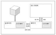
본 명세서에 설명된 예시적인 방법 및/또는 프로세스를 실행 또는 수행하는 데에 사용되는 예시적인 3D 물체 제조 시스템(10)이 도 1에 개략적으로 또한 도시되어 있다. 도시된 바와 같이, 예시적인 시스템(10)은 컴퓨팅 장치(12)를 포함할 수 있다. 컴퓨팅 장치(12)는, 예를 들어, 컴퓨팅 장치(12)가 압출된 열경화성 인쇄 장치(100)를 사용하여 또는 함께 작용하여 3D 물체를 제조할 수 있도록 압출된 열경화성 인쇄 장치(100)에 대해 입력을 수신하고 출력을 전송하도록 구성될 수 있다.An exemplary 3D
또한, 컴퓨팅 장치(12)는 데이터 저장 장치(14)를 포함할 수 있다. 데이터 저장 장치(14)는, 3D 물체의 제조 제어 및/또는 3D 설계를 하나 이상의 인쇄 프로세스로 변환하여 3D 물체를 제조하는 것을 수행하는 데에 사용하기 위한 예시적인 방법 및/또는 프로세스를 수행하거나 실행하기 위해 채용될 수 있는 것 처리 프로그램 또는 루틴(16) 및 하나 이상의 다른 유형의 데이터(18)(예를 들어, 3D 물체 설계, 컴퓨터 보조 설계(computer-aided design)(CAD) 파일, 센서 데이터, 재료 특성, 파라미터, 메트릭, 변수, 등)에 액세스하게 할 수 있다. 컴퓨팅 장치(12)는, 예를 들어 데이터를 압출된 열경화성 인쇄 장치(100)로 그리고 장치로부터 전송하기 위해 압출된 열경화성 인쇄 장치(100)에 작동 가능하게 결합된 것으로 설명될 수 있다. 예를 들어, 컴퓨팅 장치(12)는, 예를 들어 아날로그 전기 연결, 디지털 전기 연결, 무선 연결, 버스 기반 연결 등을 사용하여 압출된 열경화성 인쇄 장치(100)에 전기적으로 결합될 수 있다.
처리 프로그램 또는 루틴(16)은 계산 수학, 슬라이싱 애플리케이션, CAD 프로세스, 3D 설계 변환 알고리즘 및 프로세스, 공간 알고리즘, 프로세스 자동화 알고리즘, 매트릭스 수학, 표준화 알고리즘, 비교 알고리즘, 피드백 제어 루프, 또는 본 명세서에 설명된 하나 이상의 예시적인 방법 및/또는 프로세스를 구현하는 데에 필요한 임의의 다른 처리를 수행하기 위한 프로그램 또는 루틴을 포함할 수 있다. 데이터(18)는, 예를 들어 3D 물체 설계 데이터, 3D 물체 정보, 파라미터, 3D 인쇄 파라미터, 재료 특성, 센서 데이터, 변수, 본 명세서의 개시내용에 따라 채용된 하나 이상의 처리 프로그램 또는 루틴으로부터의 결과, 또는 본 명세서에 설명된 하나 및/또는 그 이상의 프로세스 또는 방법을 수행하기 위해 필요할 수 있는 임의의 다른 데이터를 포함할 수 있다.Processing programs or routines (16) may include computational mathematics, slicing applications, CAD processes, 3D design conversion algorithms and processes, spatial algorithms, process automation algorithms, matrix mathematics, normalization algorithms, comparison algorithms, feedback control loops, or as described herein. It may include programs or routines to perform any other processing necessary to implement one or more example methods and/or processes.
하나 이상의 실시예에서, 시스템(10)은, 예를 들어 처리 능력, 데이터 저장 장치(예를 들어, 휘발성 또는 비휘발성 메모리 및/또는 저장 요소), 입력 디바이스, 및 출력 디바이스를 포함하는 컴퓨터와 같은 프로그래밍 가능한 컴퓨터 상에서 실행되는 하나 이상의 컴퓨터 프로그램을 사용하여 구현될 수 있다. 본 명세서에 설명된 프로그램 코드 및/또는 로직은 입력 데이터에 적용되어 본 명세서에 설명된 기능을 수행하고 원하는 출력 정보를 생성할 수 있다. 출력 정보는 본 명세서에 설명되는 바와 같이 또는 공지된 방식으로 적용되는 바와 같이 하나 이상의 다른 디바이스 및/또는 방법에 대한 입력으로서 적용될 수 있다.In one or more embodiments,
본 명세서에 설명된 방법 및/또는 프로세스를 구현하는 데에 사용되는 프로그램은 임의의 프로그래밍 가능한 언어 또는 코드, 예를 들어 컴퓨터 시스템과 통신하기에 적절한 고레벨 절차 및/또는 물체 배향 프로그래밍 언어 또는 코드를 사용하여 제공될 수 있다. 임의의 그러한 프로그램은, 예를 들어 본 명세서에 설명된 절차를 수행하기 위해 적절한 디바이스가 판독될 때 컴퓨터 시스템을 구성 및 작동시키기 위해 컴퓨터 시스템(예를 들어, 처리 장치를 포함)에서 실행되는 범용 또는 특수 목적 프로그램에 의해 판독 가능한 임의의 적절한 디바이스, 예를 들어 저장 매체에 저장될 수 있다. 다시 말해서, 적어도 일 실시예에서, 시스템(10)은 컴퓨터 프로그램으로 구성된 컴퓨터 판독 가능한 저장 매체를 사용하여 구현될 수 있으며, 그렇게 구성된 저장 매체는 컴퓨터가 본 명세서에 설명된 기능을 수행하도록 특정하고 사전 정의된 방식으로 작동하게 한다. 또한, 적어도 하나의 실시예에서, 시스템(10)은 실행을 위한 코드를 포함하고 프로세서에 의해 실행될 때 본 명세서에 설명된 방법, 프로세스, 및/또는 기능과 같은 작동을 수행하도록 동작 가능한 하나 이상의 비일시적 매체에 인코딩된 로직(예를 들어, 물체 코드)에 의해 구현되는 것으로 설명될 수 있다.The programs used to implement the methods and/or processes described herein may use any programmable language or code, such as a high-level procedural and/or object orientation programming language or code suitable for communicating with a computer system. It can be provided. Any such program may be a general purpose or program that runs on a computer system (e.g., including a processing unit) to configure and operate the computer system, e.g., when read by an appropriate device to perform the procedures described herein. It may be stored in any suitable device, such as a storage medium, that can be read by a special purpose program. In other words, in at least one embodiment,
컴퓨팅 장치(12)는, 예를 들어 임의의 고정식 또는 모바일 컴퓨터 시스템(예를 들어, 제어기, 마이크로컨트롤러, 개인용 컴퓨터, 미니 컴퓨터 등)일 수 있다. 컴퓨팅 장치(12)의 정확한 구성은 제한적이지 않으며, 본질적으로 적절한 컴퓨팅 능력 및 제어 능력을 제공할 수 있는 임의의 장치가 본 명세서에 설명된 바와 같이 사용될 수 있으며, 디지털 파일은 본 명세서에 설명된 컴퓨팅 장치(12)에 의해 판독 및/또는 기입될 수 있는 디지털 비트(예를 들어, 이진수 등으로 인코딩됨)를 포함하는 임의의 매체(예를 들어, 휘발성 또는 비휘발성 메모리, CD-ROM, 자기 기록 가능한 테이프 등)일 수 있다. 또한, 본 명세서에 설명된 바와 같이, 사용자-판독 가능한 포맷의 파일은 작업자에 의해 판독 가능한 및/또는 이해 가능한 임의의 매체(예를 들어, 종이, 디스플레이 등)에 존재 가능한 데이터(예를 들어, ASCII 텍스트, 이진수, 16 진수, 10 진수, 그래픽 등)의 임의의 표현일 수 있다.
상기를 고려하여, 본 개시내용에 따른 하나 이상의 실시예에서 설명된 기능은 본 기술 분야의 숙련자에게 공지된 임의의 방식으로 구현될 수 있다는 것이 쉽게 명백할 것이다. 따라서, 본 명세서에 설명된 프로세스를 구현하기 위해 사용될 컴퓨터 언어, 컴퓨터 시스템, 또는 임의의 다른 소프트웨어/하드웨어는 본 명세서에 설명된 시스템, 프로세스 또는 프로그램(예를 들어, 그러한 시스템, 프로세스 또는 프로그램에 의해 제공되는 기능)의 범위를 제한하지 않아야 한다.In light of the above, it will be readily apparent that the functionality described in one or more embodiments according to the present disclosure may be implemented in any manner known to those skilled in the art. Accordingly, a computer language, computer system, or any other software/hardware to be used to implement a process described herein may be used to implement a system, process, or program described herein (e.g., by such system, process, or program). The scope of the provided functions must not be limited.
시스템 또는 다양한 구성 컴포넌트에 기인한 것을 비롯하여 본 개시내용에 설명된 방법 및/또는 로직은 적어도 부분적으로 하드웨어, 소프트웨어, 펌웨어 또는 이들의 임의의 조합에서 구현될 수 있다. 예를 들어, 기술의 다양한 양태는 하나 이상의 마이크로프로세서, DSP, ASIC, FPGA, 또는 임의의 다른 등가의 통합 또는 이산 로직 회로 뿐만 아니라 그러한 구성요소들의 임의의 조합, 또는 다른 디바이스를 비롯하여 하나 이상의 프로세서 내에서 구현될 수 있다. 용어 "프로세서" 또는 "처리 회로"는 일반적으로 단독으로 또는 다른 로직 회로와 조합하여 상기 로직 회로 중 임의의 것, 또는 임의의 다른 등가의 회로를 지칭할 수 있다.The methods and/or logic described in this disclosure, including those resulting from systems or various configuration components, may be implemented at least in part in hardware, software, firmware, or any combination thereof. For example, various aspects of the technology may be implemented within one or more processors, including one or more microprocessors, DSPs, ASICs, FPGAs, or any other equivalent integrated or discrete logic circuits, as well as any combination of such components, or other devices. It can be implemented in . The terms “processor” or “processing circuit” may generally refer to any of the foregoing logic circuits, alone or in combination with other logic circuits, or any other equivalent circuit.
그러한 하드웨어, 소프트웨어, 및/또는 펌웨어는 본 개시내용에서 설명된 다양한 작동 및 기능을 지원하기 위해 동일한 디바이스 내에서 또는 별도의 장치 내에서 구현될 수 있다. 또한, 설명된 구성요소 중 임의의 구성요소는 개별적이지만 상호 운용 가능한 로직 디바이스로서 함께 또는 별도로 구현될 수 있다. 예를 들어, 블록도 등을 사용하는 상이한 특징의 도시는 상이한 기능적 양태를 강조하기 위한 것이며 반드시 그러한 특징이 별도의 하드웨어 또는 소프트웨어 구성요소에 의해 실현되어야 한다는 것을 의미하지는 않는다. 오히려, 기능은 별도의 하드웨어 또는 소프트웨어 구성요소에 의해 수행되거나, 공통의 또는 별도의 하드웨어 또는 소프트웨어 구성요소 내에 통합될 수 있다.Such hardware, software, and/or firmware may be implemented within the same device or within separate devices to support the various operations and functions described in this disclosure. Additionally, any of the described components may be implemented together or separately as separate but interoperable logic devices. The illustration of different features, for example, using block diagrams, etc., is intended to emphasize different functional aspects and does not necessarily imply that such features must be realized by separate hardware or software components. Rather, the functionality may be performed by separate hardware or software components, or may be integrated within common or separate hardware or software components.
소프트웨어로 구현될 때, 본 개시내용에서 설명되는 시스템, 디바이스 및 방법에 따른 기능은 RAM, ROM, NVRAM, EEPROM, FLASH 메모리, 자기 데이터 저장 매체, 광학 데이터 저장 매체 등과 같은 컴퓨터-판독 가능한 매체 상의 명령 및/또는 로직으로서 구현될 수 있다. 명령 및/또는 로직은 본 개시내용에서 설명된 기능의 하나 이상의 양태를 지원하기 위해 하나 이상의 프로세서에 의해 실행될 수 있다.When implemented in software, the functionality of the systems, devices, and methods described in this disclosure may include instructions on a computer-readable medium, such as RAM, ROM, NVRAM, EEPROM, FLASH memory, magnetic data storage media, optical data storage media, etc. and/or may be implemented as logic. Instructions and/or logic may be executed by one or more processors to support one or more aspects of the functionality described in this disclosure.
압출된 열경화성 인쇄 장치(100)는 본 명세서에 설명된 바와 같이 3D 물체 생성 또는 인쇄를 수행할 수 있도록 임의의 하나 이상의 디바이스, 메커니즘 및 구조를 포함할 수 있다. 일반적으로, 도 2에 도시된 바와 같이, 압출된 열경화성 인쇄 장치(100)는 제1 반응물을 보유 또는 수용하기 위한 적어도 제1 반응물 챔버 및 하나 이상의 추가 반응물 챔버, 또는 추가 또는 제n 반응물을 보유 또는 수용하기 위한 제n 반응물 챔버를 포함할 수 있다. 반응 챔버는 혼합 챔버에 작동 가능하게 결합될 수 있어 반응물이 혼합되어 본 명세서에 설명된 바와 같이 열경화성 생성물을 생성하거나 제공할 수 있다. 혼합 챔버는 압출 노즐에 작동 가능하게 결합될 수 있으며, 압출 노즐은 3D 물체가 인쇄되거나 형성되는 제조 챔버로 열경화성 생성물을 전달할 수 있다.Extruded
일부가 도 2에 도시된 시스템(100)의 부분 또는 항목 각각은 대응하는 모니터링 장치가 작동 가능하게 결합될 수 있다. 예를 들어, 장치(100)는 제1 반응물 챔버에 작동 가능하게 결합되어 그와 관련된 하나 이상의 파라미터 및/또는 변수를 모니터링하는 제1 반응물 챔버 모니터링 장치, 및 제n 반응물 챔버에 작동 가능하게 결합되어 그와 관련된 하나 이상의 파라미터 및/또는 변수를 모니터링하는 제n 반응물 챔버 모니터링 장치를 포함할 수 있다. 또한, 장치(100)는 혼합 챔버, 압출 노즐, 및 제조 챔버에 각각 작동 가능하게 결합되어 그와 관련된 하나 이상의 파라미터 및/또는 변수를 모니터링하는 혼합 챔버 모니터링 장치, 압출 노즐 모니터링 장치, 및 제조 챔버 모니터링 장치를 포함할 수 있다.Each portion or item of
일부가 도 2에 도시된 시스템(100)의 부분 또는 항목 각각은 대응하는 제어 장치가 작동 가능하게 결합될 수 있다. 예를 들어, 장치(100)는 제1 반응물 챔버에 작동 가능하게 결합되어 그와 관련된 하나 이상의 설정, 파라미터, 및/또는 프로세스를 제어, 수정, 또는 조절하는 제1 반응물 챔버 제어 장치, 및 제n 반응물 챔버에 작동 가능하게 결합되어 그와 관련된 하나 이상의 설정, 파라미터, 및/또는 프로세스를 제어하는 제n 반응물 챔버 제어 장치를 포함할 수 있다. 또한, 장치(100)는 혼합 챔버, 압출 노즐, 및 제조 챔버에 각각 작동 가능하게 결합되어 그와 관련된 하나 이상의 설정, 파라미터, 및/또는 프로세스를 제어하는 혼합 챔버 제어 장치, 압출 노즐 제어 장치, 및 제조 챔버 제어 장치를 포함할 수 있다.Each portion or item of
도 3은 예시적인 3D 물체 제조 시스템의 블록도이다. 도 3에서, 슬라이싱 애플리케이션 소프트웨어는 물체 설명을 제어기에 전송한다. 제어기는 제어 명령을 3D 프린터에 전송하여 3D 물체를 인쇄한다. 3D 프린터는 제어기에 피드백을 전송하고, 제어기는 이어서 피드백을 슬라이싱 애플리케이션에 전송한다.3 is a block diagram of an exemplary 3D object manufacturing system. In Figure 3, the slicing application software transmits the object description to the controller. The controller prints a 3D object by sending control commands to the 3D printer. The 3D printer sends feedback to the controller, which then sends feedback to the slicing application.
도 4는 2개의 상이한 열경화성 성분을 갖는 인쇄된 3D 물체이다. 3D 물체는 별 형상이다. 별의 내부의 더 어두운 색상 부분은 단단한 열경화성 재료로 구성된다. 별의 외부의 더 밝은 색상 부분은 부드러운 열경화성 재료로 구성된다.Figure 4 is a printed 3D object with two different thermoset components. The 3D object is star-shaped. The darker parts of the star's interior are made of hard thermoset material. The brighter colored parts of the star's exterior are made of a soft thermoset material.
도 5는 예시적인 3D 물체 제조 시스템의 블록도이다. 도 5에서, 슬라이싱 애플리케이션 소프트웨어는 물체 설명을 제어기에 전송한다. 제어기는 제어 명령을 3D 프린터에 전송하여 3D 물체를 인쇄한다. 3D 프린터는 제어기에 피드백을 전송하고, 제어기는 이어서 피드백을 슬라이싱 애플리케이션에 전송한다. 3D 프린터는 습도, 온도 및 건조 공기 유동을 모니터링하고 제어하기 위한 제어기를 포함한다.Figure 5 is a block diagram of an example 3D object manufacturing system. In Figure 5, the slicing application software transmits the object description to the controller. The controller prints a 3D object by sending control commands to the 3D printer. The 3D printer sends feedback to the controller, which then sends feedback to the slicing application. The 3D printer includes controllers to monitor and control humidity, temperature, and dry air flow.
다양한 3차원(3D) 물체 제조 방법 및 시스템은, 예를 들어 2016년 12월 6일자로 출원된 미국 가출원 제62/430,919호, 2017년 6월 23일자로 출원된 미국 가출원 제62/524,214호, 및 발명의 명칭이 "열경화성 수지로부터 3차원 물체의 제조(MANUFACTURE OF THREE DIMENSIONAL OBJECTS FROM THERMOSETS)"이고 본 출원과 동일 날짜로 출원된 PCT 특허 출원과 같이 본 명세서에 설명된 예시적인 방법 및 시스템과 함께 사용될 수 있고, 이들 각각은 본 명세서에 그 전체가 참조로 포함된다.Various three-dimensional (3D) object manufacturing methods and systems are described, for example, in U.S. Provisional Application No. 62/430,919, filed December 6, 2016, U.S. Provisional Application No. 62/524,214, filed June 23, 2017; and the PCT patent application entitled “MANUFACTURE OF THREE DIMENSIONAL OBJECTS FROM THERMOSETS” and filed on the same date as this application, along with exemplary methods and systems described herein. may be used, each of which is incorporated herein by reference in its entirety.
여기에 인용된 모든 특허, 특허 문헌 및 참고 문헌은 각각이 개별적으로 통합된 것처럼 그 전체가 포함된다. 본 개시내용은 예시적인 실시예를 참조하여 제공되었으며 제한적인 의미로 해석되도록 의도되지 않는다. 전술한 바와 같이, 본 기술 분야의 숙련자는 다른 다양한 예시적인 용례가 본 명세서에 설명된 장치 및 방법의 유리한 특성의 이점을 위치하기 위해 본 명세서에 설명된 기술을 사용할 수 있음을 인지할 것이다. 예시적인 실시예의 다양한 수정, 뿐만 아니라 본 개시내용의 추가 실시예가 이 설명을 참조하면 명백해질 것이다.All patents, patent documents and references cited herein are incorporated in their entirety as if each were individually incorporated. This disclosure is provided with reference to illustrative embodiments and is not intended to be interpreted in a limiting sense. As noted above, those skilled in the art will recognize that a variety of other exemplary applications may utilize the techniques described herein to take advantage of the advantageous features of the devices and methods described herein. Various modifications of the exemplary embodiments, as well as additional embodiments of the present disclosure, will become apparent upon reference to this description.
예yes
본 명세서에 개시된 3D 물체 제조 시스템 및 방법은 이제 다음의 예를 참조하여 더 상세히 설명된다. 이들 예는 단지 예시의 목적으로 제공되며, 본 명세서에 설명된 실시예는 이들 예로 제한되는 것으로 해석되어서는 안된다. 오히려, 실시예는 본 명세서에 제공된 교시의 결과로서 증거가 되는 모든 변형을 포함하도록 해석되어야 한다.The 3D object manufacturing systems and methods disclosed herein are now described in more detail with reference to the following examples. These examples are provided for illustrative purposes only, and the embodiments described herein should not be construed as limited to these examples. Rather, the examples should be construed to include all modifications evidenced as a result of the teachings provided herein.
예 1AExample 1A
정확한 양의 여러 반응성 성분을 분배할 수 있는 장치를 사용하여 다양한 물리적 특성을 갖는 3D 물체를 만들 수 있다.Using devices that can dispense precise amounts of multiple reactive ingredients, 3D objects with a variety of physical properties can be created.
프로세스process
충전된 별을 묘사한 3D 모델(도 4에 도시됨)은 Solidworks 2018 CAD 소프트웨어를 사용하여 작성되어 STL 파일로 내보냈다. 이 모델은 (1) 융기된 윤곽선 및 (2) 내부 평탄 영역을 갖게 설계되었다.A 3D model depicting a charged star (shown in Figure 4) was created using Solidworks 2018 CAD software and exported as an STL file. The model was designed to have (1) a raised outline and (2) an internal flat area.
STL 파일은 기성품인 "슬라이싱" 애플리케이션을 사용하여 처리되어 고유한 열경화성 재료로 각각의 개별 영역을 생성하는 데에 필요한 작동의 G-코드 설명을 생성하였다.The STL files were processed using an off-the-shelf "slicing" application to generate a G-code description of the operations needed to create each individual region with its own thermoset material.
별의 외부 융기된 영역인 영역 1은 적색과 쇼어 60A의 경도를 갖는 열경화성 수지 1을 사용하여 구축되었다. 별의 내부 충전된 영역인 영역 2는 녹색과 쇼어 95A의 경도를 갖는 열경화성 수지 2를 사용하여 구축되었다.Region 1, the outer raised region of the star, was constructed using thermoset 1, which is red and has a hardness of Shore 60A. Region 2, the inner charged region of the star, was constructed using thermoset 2, which is green and has a hardness of Shore 95A.
표 1에 나타낸 바와 같이, 열경화성 수지 1은 2개의 반응성 성분 A1 및 B1을 사용하여 혼합함으로써 제조되고; 열경화성 수지 1은 2개의 반응성 성분 A2 및 B2를 사용하여 혼합함으로써 제조되었다:As shown in Table 1, thermosetting resin 1 is prepared by mixing using two reactive components A1 and B1; Thermoset 1 was prepared by mixing two reactive components A2 and B2:

이소시아네이트:프리폴리머의 비율은 반응성 성분 A2와 비교하여 반응성 성분 A1에 대해 더 낮았다. 반응성 성분 B2는 반응성 성분 B1과 비교하여 프리폴리머의 중량%가 더 컸다. 이 모델은 수정된 CSD-30 압출기를 갖는 Hyrel Engine SR 프린터를 사용하여 2개의 별도의 작업으로 인쇄되었다.The ratio of isocyanate:prepolymer was lower for reactive component A1 compared to reactive component A2. Reactive component B2 had a greater weight percent of prepolymer compared to reactive component B1. This model was printed in two separate runs using a Hyrel Engine SR printer with a modified CSD-30 extruder.
작업 1task 1
외부 별은 열경화성 수지 1을 사용하여 인쇄되어 슬라이싱 애플리케이션에 의해 규정된 6개의 기하학적 패턴층을 생성하였다. 각각의 층은 다음 파라미터를 사용하여 퇴적되었다.The outer star was printed using thermoset 1, creating six geometrically patterned layers defined by a slicing application. Each layer was deposited using the following parameters:
비드 높이:0.8 mmBead height: 0.8 mm
비드 폭:1.2 mmBead Width: 1.2 mm
선형 속도:25 mm/sLinear speed: 25 mm/s
유량:24 mm3/sFlow rate: 24 mm3 /s
작업 2task 2
내부 충전된 별은 열경화성 수지 2를 사용하여 인쇄되어 동일한 파라미터를 갖는 슬라이싱 애플리케이션에 의해 규정된 4개의 기하학적 패턴층을 생성하였다.The internally charged stars were printed using thermoset 2, creating four geometrically patterned layers defined by a slicing application with identical parameters.
도 4에 도시된 인쇄된 물체는, (1) 각각의 열경화성 재료가 CAD 프로그램에 의해 생성된 3D 모델의 치수적으로 정확한 표현을 형성할 수 있고, (2) 2개의 열경화성 재료가 결합되어 고유한 특성, 이 경우에 색상 및 경도를 갖는 단일 물체를 형성한다는 것을 입증한다.The printed object shown in Figure 4 is designed so that (1) each thermoset material can form a dimensionally accurate representation of a 3D model generated by a CAD program, and (2) the two thermoset materials can be combined to form a unique It demonstrates that they form a single object with properties, in this case color and hardness.
예 1BExample 1B
예 1A는 언제든지 2개의 반응성 성분만을 압출할 수 있는 Hyrel 압출기를 사용하여 생성되었다. 다수의 반응성 성분을 결합하고 압출할 수 있는 압출기를 추가하면 다음이 가능하게 된다:Example 1A was produced using a Hyrel extruder capable of extruding only two reactive components at any one time. Adding an extruder that can combine and extrude multiple reactive components allows you to:
1. 동시에 압출되는 고유한 특성을 가진 영역; 및1. Areas with unique properties that are extruded simultaneously; and
2. 특정한 고유 특성을 가진 반응성 성분으로부터 특정한 특성을 생성하도록 정확한 비율로 혼합될 반응성 성분.2. Reactive components to be mixed in precise proportions to produce specific properties from reactive components with specific intrinsic properties.
도 6은 최대 8개의 반응성 성분을 결합할 수 있는 압출기를 도시한다.Figure 6 shows an extruder capable of combining up to eight reactive components.
도 6의 이 유형의 압출기는, 선택적으로 반응성 성분 A1 및 B1을 압출하여 열경화성 수지 1을 생성하는 한편 도 1에 도시된 별의 외부 융기된 영역을 묘사하고 반응성 성분 A2 및 B2를 압출하여 열경화성 수지 2를 생성하는 한편 도 4에 도시된 별의 내부 충전된 영역을 묘사함으로써, 단일 작업으로 별을 생성할 수 있다. 게다가, 이 유형의 압출기는 열경화성 수지 1과 2를 특정 비율로 결합함으로써 혼합된 특성을 가진 영역을 생성할 수 있다.This type of extruder in Figure 6 selectively extrudes reactive components A1 and B1 to produce thermoset 1, while delineating the outer raised regions of the star shown in Figure 1 and extruding reactive components A2 and B2 to produce thermoset 1. By creating Additionally, this type of extruder can create regions with mixed properties by combining thermosets 1 and 2 in specific ratios.
예를 들어, 도 6의 압출기는 표 2에 나타낸 바와 같이 사용될 수 있다:For example, the extruder of Figure 6 can be used as shown in Table 2:

이 방식으로, 반응성 성분들을 결합하면 경도, 색상, 광학 굴절률, 밀도(폼), 및 다공성(폼)을 비롯한 특정한 특성을 정확한 비율로 생성할 수 있으며 구성 중인 모델의 규정된 영역 내에 혼합된 특성을 생성할 수 있다. "슬라이싱" 애플리케이션에 각각의 반응성 성분과 각각의 특정한 특성의 혼합 비율간의 관계를 이해하도록 메커니즘을 제공함으로써, 연속적인 특성 스펙트럼이 생성될 수 있다.In this way, reactive components can be combined to produce specific properties, including hardness, color, optical refractive index, density (foam), and porosity (foam), in precise proportions and blended properties within defined regions of the model being constructed. can be created. By providing a "slicing" application with a mechanism to understand the relationship between the mixing ratio of each reactive component and each particular property, a continuous property spectrum can be generated.
예를 들어, 모델 내의 각 지점의 경도가 특정되는 단일 작업으로 예 1A에 설명된 별을 인쇄하는 것은 다음 단계에 의해 달성된다.For example, printing the star described in Example 1A in a single operation where the longitude of each point in the model is specified is accomplished by the following steps.
슬라이싱 애플리케이션 내에 각각의 반응성 성분 A1, A2, B1 및 B2의 설명을 저장함으로써 그리고 독점 알고리즘 내에서 그러한 파라미터를 사용함으로써, 슬라이싱 애플리케이션은 파라미터 값을 생성하는 데에 사용되는 유량에 대한 설명이 있는 G-코드를 생성한다.By storing a description of each reactive component A1, A2, B1 and B2 within the slicing application and using those parameters within a proprietary algorithm, the slicing application can generate a G- with a description of the flow rates used to generate the parameter values. Generate code.
이 G-코드 설명은 적절하게 구성된 3D 물체 제조 시스템이 4개의 반응성 성분의 유량을 제어하게 하여 쇼어 60A와 쇼어 90A 사이의 혼합된 경도를 갖는 열경화성 재료를 생성한다.This G-code description allows a properly configured 3D object manufacturing system to control the flow rates of the four reactive components to produce a thermoset material with a blended hardness between Shore 60A and Shore 90A.
적절한 비율로 착색된 색조를 추가하면 전술한 시스템이 혼합된 색상을 생성하게 된다. 적절한 비율로 물을 첨가하면 전술한 시스템이 특정 밀도 및 다공성을 갖는 폼을 생성하게 된다.Adding colored tints in appropriate proportions results in the above-described system producing mixed colors. Addition of water in appropriate proportions results in the above-described system producing a foam with a specific density and porosity.
예 2Example 2
예 1에 설명된 압출 시스템의 혼합 챔버 또는 압출 노즐 내의 장애물은 다양한 이유로 발생할 수 있다. 장애물의 식별 및 시정 조치의 시작은 열경화성 수지로 3D 물체를 생성하기 위한 제조 시스템 개발의 기본이다.Obstructions within the mixing chamber or extrusion nozzles of the extrusion system described in Example 1 can occur for a variety of reasons. Identification of obstacles and initiation of corrective action is fundamental to the development of manufacturing systems for creating 3D objects from thermosets.
장애물을 식별하기 위해, 압출 시스템의 작동 파라미터 및 반응성 성분 유동을 모니터링하고 정상적인 작동 조건과 비교해야 한다.To identify obstructions, the extrusion system's operating parameters and reactive component flows must be monitored and compared to normal operating conditions.
도 7은 도 6에 도시된 것과 유사한 압출 시스템을 도시한다. 양쪽 시스템 모두 혼합 챔버에 압출 노즐을 공급하는 여러 개의 동일한 ViscoTec 5/5 액체 펌프를 사용한다. 도 4는 단순화를 위해 2개의 액체 펌프를 도시한다.Figure 7 shows an extrusion system similar to that shown in Figure 6. Both systems use multiple identical ViscoTec 5/5 liquid pumps that feed extrusion nozzles into the mixing chamber. Figure 4 shows two liquid pumps for simplicity.
모터 전류/토크motor current/torque
액체 펌프를 구동하는 각각의 모터에 의해 인입되는 전류가 측정될 수 있다. DC 모터의 경우, 액체 펌프를 구동하는 데에 필요한 토크는 모터에 의해 인입된 전류에 비례할 수 있다.The current drawn by each motor driving the liquid pump can be measured. In the case of a DC motor, the torque required to drive the liquid pump may be proportional to the current drawn by the motor.
압출 시스템의 장애물로 인해 액체 펌프를 구동하는 모터가 더 많은 토크를 전달하므로 모터가 더 높은 전류를 인입하게 된다.Obstacles in the extrusion system cause the motor driving the liquid pump to deliver more torque, causing the motor to draw higher currents.
정상 작동에서, ViscoTec 5/5 액체 펌프 범위를 구동하는 모터에 의해 인입된 전류는 0.5A 내지 1.25A이다. 1.25A를 초과하는 피크가 가능하지만, 1.25A보다 큰 확장 전류 인입은 장애물의 존재를 강력하게 시사한다.In normal operation, the current drawn by the motor driving the ViscoTec 5/5 liquid pump range is 0.5A to 1.25A. Although peaks exceeding 1.25A are possible, extended current draw greater than 1.25A strongly suggests the presence of an obstruction.
반응성 성분 압력reactive component pressure
반응성 성분의 압력은 압력 변환기를 사용하여 측정될 수 있다. 각각의 반응성 성분의 압력은 압출 노즐 전에, 액체 펌프 이전에 그리고 혼합 챔버 내에서 측정될 수 있다.The pressure of the reactive component can be measured using a pressure transducer. The pressure of each reactive component can be measured before the extrusion nozzle, before the liquid pump and within the mixing chamber.
장애물은 혼합 챔버 내의 압력 증가를 특징으로 할 수 있으며 혼합 챔버 내의 압력이 액체 펌프 이전의 압력보다 높아질 때 강력하게 시사된다.The obstruction may be characterized by an increase in pressure within the mixing chamber and is strongly indicated when the pressure within the mixing chamber becomes higher than the pressure prior to the liquid pump.
실제 반응성 성분 압력은 성분의 점도에 따라 달라지지만, 점도가 40,000 cp인 성분의 경우, 액체 펌프 이전의 80 psi의 압력은 통상적이고 압출 노즐에서의 압력이 증가하여 증가된 유동을 생성하며 혼합 챔버 내의 압력은 60 psi 미만으로 유지되어야 한다.Actual reactive component pressure will vary depending on the viscosity of the component, but for a component with a viscosity of 40,000 cp, a pressure of 80 psi prior to the liquid pump is typical and increases the pressure at the extrusion nozzle, creating increased flow within the mixing chamber. Pressure should be maintained below 60 psi.
반응성 성분 유량Reactive component flow rate
반응성 성분의 유량은 다양한 센서 기술을 사용하여 측정될 수 있다. 각각의 반응성 성분의 유량은 액체 펌프 이전 및 혼합 챔버의 유출에서 측정된다.The flow rate of reactive components can be measured using a variety of sensor technologies. The flow rate of each reactive component is measured prior to the liquid pump and at the outlet of the mixing chamber.
장애물은 재료 유량의 완전한 또는 부분적인 감소를 유발할 수 있다. 불행히도, 재료 결핍 또는 압력 실패가 또한 재료 유량이 감소하거나 완전히 정지하게 할 수 있다. 액체 펌프 이전 및 혼합 챔버의 유출에서 압력 및 재료 유량을 모두 측정함으로써, 장애물의 존재가 확인된다. 장애물의 가능성을 식별하는 데에 사용되는 로직 테이블을 아래 표 3에 나타낸다:Obstacles can cause complete or partial reduction of material flow rate. Unfortunately, material starvation or pressure failure can also cause material flow to decrease or stop completely. By measuring both pressure and material flow rate prior to the liquid pump and at the outlet of the mixing chamber, the presence of an obstruction is confirmed. The logic table used to identify possible obstacles is shown in Table 3 below:

ViscoTec 5/5 액체 펌프는 0.05 ml/s 내지 6.0 ml/s의 속도로 액체를 정확하게 펌핑할 수 있다.The ViscoTec 5/5 liquid pump can accurately pump liquids at rates between 0.05 ml/s and 6.0 ml/s.
반응성 성분 질량Reactive ingredient mass
정상적인 작동에서, ViscoTec 5/5 압출기는 압출된 반응성 성분의 체적을 매우 정확하게 계량할 수 있다.In normal operation, the ViscoTec 5/5 extruder is capable of metering the volume of extruded reactive ingredients with high accuracy.
압출되도록 의도된 재료의 누적 체적은 물체를 생산하는 전체에 걸쳐 3D 프린터에서 실행되는 G-Code 인터프리터에 의해 나타난다.The cumulative volume of material intended to be extruded is represented by a G-Code interpreter running on the 3D printer throughout production of the object.
빌드 표면의 각각의 코너에 힘 센서를 추가함으로써, 압출된 재료의 질량은 3D 물체를 생산하는 전체에 걸쳐 측정될 수 있다.By adding force sensors to each corner of the build surface, the mass of extruded material can be measured throughout the production of a 3D object.
압출될 재료의 의도된 질량과 빌드 표면에 장착된 힘 센서에 의해 측정된 실제 질량 사이의 차이를 모니터링함으로써, 퇴적된 재료의 실제 질량이 의도된 것보다 현저히 적으면, 잠재적인 장애물을 시사한다고 결정될 수 있다.By monitoring the difference between the intended mass of material to be extruded and the actual mass measured by a force sensor mounted on the build surface, it can be determined that if the actual mass of material deposited is significantly less than intended, indicating a potential obstruction. You can.
결합된 반응성 성분의 색상Color of bound reactive components
압출 노즐에 AMS AS7261 Tri-stimulus XYZ_NIR 센서와 같은 색상 센서를 장착함으로써, 결합된 열경화성 수지의 색상이 측정될 수 있다.By equipping the extrusion nozzle with a color sensor, such as the AMS AS7261 Tri-stimulus XYZ_NIR sensor, the color of the bonded thermoset can be measured.
각각의 반응성 성분의 색상은 색조를 추가하여 제어될 수 있다. 최종 열경화성 수지의 색상은 각각의 성분에 존재하는 색조의 혼합물에 의해 제어될 수 있다. 상기 예에서, 반응성 성분 A1은 적색 색조를 함유하고, 반응성 성분 A2는 황색 색조를 함유하고, 반응성 성분 B1은 청색 색조를 함유하고, 반응성 성분 B2는 청색 색조를 함유한다.The color of each reactive ingredient can be controlled by adding a tint. The color of the final thermoset resin can be controlled by the mixture of shades present in each component. In the above example, reactive component A1 contains a red tint, reactive component A2 contains a yellow tint, reactive component B1 contains a blue tint, and reactive component B2 contains a blue tint.
그러한 임의의 성분들을 결합하면 고유한 색상의 열경화성 수지를 생성할 수 있다. 임의의 성분의 양의 부재 또는 감소는 압출된 열경화성 수지가 어느 정도 상이한 색상을 가질 수 있게 한다. 누락된 색상 성분의 식별은 해당 성분에 대한 압출 시스템에서 잠재적인 장애물을 시사한다.Combining such random ingredients can produce thermosets of unique colors. Absence or reduction in the amount of any component allows the extruded thermoset resin to have a somewhat different color. Identification of a missing color component suggests a potential obstacle in the extrusion system for that component.
결합된 반응성 성분의 스펙트럼 분석Spectral analysis of bound reactive components
압출 노즐 내에 AMS AS7265x 스마트 스펙트럼 센서와 같은 다중 스펙트럼 촬상 센서를 장착함으로써, 압출된 재료의 화학적 조성이 특성화될 수 있다.By mounting a multispectral imaging sensor, such as the AMS AS7265x smart spectral sensor, within the extrusion nozzle, the chemical composition of the extruded material can be characterized.
압출된 재료의 예측된 화학 조성을 센서에 의해 측정된 것과 비교함으로써, 특정 반응성 성분과 관련된 화학 성분의 부재가 있다면 해당 성분에 대한 압출 시스템에서 잠재적인 장애물을 시사하게 된다.By comparing the predicted chemical composition of the extruded material to that measured by the sensor, the absence of chemical components associated with a particular reactive component suggests a potential obstacle in the extrusion system for that component.
잠재적 조치potential action
·지연을 개시하고 작업자에게 알린다·Initiate delays and notify workers
·자동화 세정 사이클을 개시하고 작업자에게 알린다·Initiates automated cleaning cycle and notifies operator
·영향을 받는 재료의 자동화 퍼지를 개시한다·Initiates automated purge of affected materials
·작업자가 수동 세정 절차를 시작하도록 요청한다Ask the operator to begin the manual cleaning procedure
장애물 식별의 최적화Optimization of obstacle identification
각 센서 판독값에 대한 이력 데이터를 수집하여 3D 프린터 제어 시스템에 저장하여 장애물의 식별을 최적화할 수 있다. 예를 들어, 각 유형의 반응성 성분의 압력 한계는 장애물을 시사하는 센서 값을 보다 정확하게 이해하도록 정상 작동 중에 모니터링 및 업데이트된다.Historical data for each sensor reading can be collected and stored in the 3D printer control system to optimize identification of obstacles. For example, the pressure limits of each type of reactive component are monitored and updated during normal operation to provide a more accurate understanding of sensor values indicative of obstructions.
예 3Example 3
예 2에 설명된 시스템은 유량 센서를 사용하여 각각의 성분 압출 시스템 내에서 장애물을 식별하는 데에 도움을 준다. 이들 센서는 또한 정상 작동 중에도 압출기 노즐과 같은 하드웨어의 반응성 성분 파라미터 또는 공차의 변동에 의해 야기된 유량의 불일치를 보상하도록 사용될 수 있다.The system described in Example 2 uses flow sensors to help identify obstructions within each component extrusion system. These sensors can also be used to compensate for flow rate inconsistencies caused by variations in tolerances or reactive component parameters of hardware, such as extruder nozzles, even during normal operation.
도 8에서 알 수 있는 바와 같이, 각각의 반응성 성분의 유량의 작은 변화는 인쇄된 비드 높이 및 폭에 비선형적인 변화를 야기할 수 있다.As can be seen in Figure 8, small changes in the flow rate of each reactive component can cause non-linear changes in printed bead height and width.
도 8은 ViscoTec Duo 압출기와 함께 독일 RepRap x400i LAM 프린터를 사용하여 인쇄된 3개의 비드의 단면을 도시한다. 각각의 비드는 표 4에 나타낸 바와 같이 2개의 반응성 성분 A1 및 B1에 의해 구성된 열경화성 재료로 인쇄되었다.Figure 8 shows cross-sections of three beads printed using a German RepRap x400i LAM printer with a ViscoTec Duo extruder. Each bead was printed with a thermoset material composed of two reactive components A1 and B1 as shown in Table 4.

40,000cp의 미반응 점도를 가진 위에 나타낸 재료의 경우For the material shown above with an unreacted viscosity of 40,000 cp.
100% 유량(6.0 mm3/s)이 비드를 생성하고;100% flow rate (6.0 mm3 /s) produces beads;
·비드 폭:0.9 mmBead width: 0.9 mm
·비드 높이0.675 mmBead height 0.675 mm
75% 유량(4.0 mm3/s)이 비드를 생성하며;75% flow rate (4.0 mm3 /s) produces beads;
·비드 폭:0.782 mmBead width: 0.782 mm
·비드 높이0.645 mmBead height 0.645 mm
125% 유량(8.0 mm3/s)이 비드를 생성하고;125% flow rate (8.0 mm3 /s) produces beads;
·비드 폭:1.017 mmBead width: 1.017 mm
·비드 높이0.766 mmBead height 0.766 mm
비드 폭, 특히 비드 높이의 변화는 인쇄된 물체의 품질을 저하시킬 수 있다. 원하는 유량과 실제 유량 사이의 차이를 모니터링함으로써, 비례, 미분, 적분(Proportional, Derivative, Integral)(PID) 제어 알고리즘은 제어 루프 피드백 메커니즘을 사용하여 원하는 유량을 최적화하도록 채용되어 보다 정확하고 안정적인 유량 및 보다 일관된 인쇄된 비드를 초래할 수 있다.Changes in bead width, especially bead height, can degrade the quality of the printed object. By monitoring the difference between the desired flow rate and the actual flow rate, Proportional, Derivative, Integral (PID) control algorithms are employed to optimize the desired flow rate using a control loop feedback mechanism, resulting in a more accurate and stable flow rate and This can result in more consistent printed beads.
예 4Example 4
이전 예에서 설명된 압출 노즐은 특정 환경에서 반응된 열경화성 재료의 일부를 노즐의 팁 상에 축적할 수 있다. 이 재료의 "방울(blob)"은 인쇄물을 마킹하는 임의의 이전에 인쇄된 재료를 방해하고 압출 노즐을 잠재적으로 오정렬시킬 수 있다.The extrusion nozzle described in the previous example may under certain circumstances accumulate a portion of the reacted thermoset material on the tip of the nozzle. These “blobs” of material can disrupt any previously printed material marking the print and potentially misalign the extrusion nozzle.
슬라이싱 애플리케이션은 인쇄 중에 자동화 팁 세정 프로세스를 완료할 기회를 식별할 수 있다. 팁 세정 프로세스는 압출기가 세정 와이프가 압출 노즐로부터 임의의 축적된 재료를 제거할 수 있는 빌드 플랫폼의 에지로 이동하게 할 수 있다.The slicing application can identify opportunities to complete the automated tip cleaning process during printing. The tip cleaning process may cause the extruder to move to the edge of the build platform where a cleaning wipe can remove any accumulated material from the extrusion nozzle.
세정 와이프는 각 인쇄의 시작에 위치되며 인쇄가 완료된 후에 교체될 수 있다.A cleaning wipe is placed at the beginning of each print and can be replaced after the print is complete.
예 5Example 5
설명된 것과 같은 열경화성 재료는 이들 재료가 포함된 환경 조건에 의해 영향을 받을 수 있다.Thermoset materials such as those described can be affected by the environmental conditions in which they are contained.
부분적으로 반응된 열경화성 재료의 점도, 유량 및 반응 속도는 온도에 따라 달라질 수 있다.The viscosity, flow rate, and reaction rate of partially reacted thermoset materials can vary with temperature.
상대 습도가 높은 환경에서 열경화성 재료를 퇴적하면 경화된 재료에 기포가 발생할 수 있다.Depositing thermoset materials in environments with high relative humidity may cause blisters to form in the cured material.
독일 RepRap x400i LAM 프린터는 환경 조건이 모니터링되고 제어되게 하는 통합형 센서 및 제어 시스템을 갖는 밀봉된 인클로저에 의해 둘러싸인다.The German RepRap x400i LAM printer is enclosed by a sealed enclosure with integrated sensors and control systems that allow environmental conditions to be monitored and controlled.
인클로저는 0%의 상대 습도를 갖는 저온(15℃) 공기를 제공하는 공기 라인에 연결되고 양압 상태로 유지된다. 인클로저 내에 15% 미만의 상대 습도를 유지하기 위한 속도로 공기가 유입된다. 온도는 15℃ 내지 25℃의 일정한 온도로 유지될 수 있다. 일관된 온도는 유리한 3D 인쇄 조건을 제공할 수 있다.The enclosure is connected to an air line providing cold (15°C) air with 0% relative humidity and maintained at positive pressure. Air is introduced at a rate to maintain a relative humidity of less than 15% within the enclosure. The temperature can be maintained at a constant temperature of 15°C to 25°C. Consistent temperatures can provide favorable 3D printing conditions.
예 6Example 6
예 5에 설명된 바와 같이, 열경화성 재료의 점도, 유량 및 반응 속도는 온도에 의존할 수 있다.As illustrated in Example 5, the viscosity, flow rate, and reaction rate of a thermoset material can be dependent on temperature.
열경화성 재료의 온도, 빌드 표면(빌드 판)의 온도 및 전술한 인클로저 내의 환경 온도를 모니터링함으로써, 다음을 비롯한 다수의 인쇄 파라미터가 온도에 대해 최적화될 수 있다;By monitoring the temperature of the thermoset material, the temperature of the build surface (build plate), and the environmental temperature within the aforementioned enclosure, a number of printing parameters can be optimized for temperature, including:
a. 열경화성 생성물의 층당 시간a. Time per layer for thermoset products
b. 압출된 열경화성 생성물의 유량, 및b. flow rate of the extruded thermoset product, and
c. 압출된 열경화성 생성물의 점도c. Viscosity of extruded thermoset products
층당 시간hours per floor
각각의 열경화성 재료는 관련 반응 속도를 갖는다. 이 속도는 재료가 겔 상태에 도달하는 속도의 지표를 제공할 수 있다. 반응 속도 및 이에 따라 겔 상태에 도달하는 데에 걸리는 시간은 온도에 의존할 수 있다. 온도가 증가함에 따라 반응 속도가 증가하고 겔 상태에 도달하는 데에 걸리는 시간이 감소한다.Each thermoset material has an associated reaction rate. This rate can provide an indication of the rate at which the material reaches a gel state. The reaction rate and thus the time taken to reach the gel state may depend on temperature. As the temperature increases, the reaction rate increases and the time it takes to reach the gel state decreases.
도 9는 예 3에 설명된 재료로 인쇄된 오프셋 피라미드를 도시한다. 이 재료는 25℃에서 약 90 초 내에 겔 상태에 도달한다. 이 점에서, 재료는 자립형이며 유동에 저항한다.Figure 9 shows an offset pyramid printed with the materials described in Example 3. This material reaches a gel state in about 90 seconds at 25°C. At this point, the material is self-supporting and resists flow.
오프셋 피라미드 인쇄물은 다음의 파라미터로 인쇄된 약 50개의 층을 포함한다.An offset pyramid print contains approximately 50 layers printed with the following parameters:
·비드 높이:0.675 mmBead height: 0.675 mm
·비드 폭:0.75 mmBead width: 0.75 mm
·선형 속도:12 mm/s·Linear speed: 12 mm/s
·유량:6.075 mm3/s·Flow rate: 6.075 mm3 /s
각각의 새로운 층은 겔 상태에 도달한 이전 층 위로 압출될 수 있다. 각 층의 면적이 감소되기 때문에, 각 층을 인쇄하는 데에 필요한 시간도 피라미드의 베이스에서 약 3.5 분으로부터 피라미드의 피크에서 10 초 미만으로 감소한다.Each new layer can be extruded over the previous layer, which has reached a gel state. Because the area of each layer is reduced, the time required to print each layer also decreases from about 3.5 minutes at the base of the pyramid to less than 10 seconds at the peak of the pyramid.
층의 대략 절반이 인쇄되면, 층을 인쇄하는 데에 걸리는 시간이 겔 상태에 도달하는 데에 걸리는 시간보다 짧으며, 후속 층이 액체 표면 상에 퇴적되어 인쇄가 불안정해지게 된다.Once approximately half of the layers have been printed, the time it takes to print a layer is less than the time it takes to reach the gel state, and subsequent layers are deposited on the liquid surface, making the print unstable.
안정적인 물체를 생성하기 위해, 각각의 층은 다음 층이 퇴적되기 전에 겔 상태에 도달해야 한다. 이는 2개의 방식으로 달성할 수 있다.To create a stable object, each layer must reach a gel state before the next layer is deposited. This can be achieved in two ways.
a. 이전 층이 겔 상태에 도달하게 하도록 인쇄가 일시 중지될 수 있다.a. Printing may be paused to allow the previous layer to reach a gel state.
각 일시 정지 기간은 다음과 같다;The duration of each suspension is as follows;
일시 정지 시간 = 겔 시간 - 층 인쇄 시간Pause Time = Gel Time - Layer Print Time
예를 들어, 퇴적하는 데에 30 초가 걸리는 층은 다음 층이 퇴적되기 전에 60 초 지연된다.For example, a layer that takes 30 seconds to deposit will have a 60 second delay before the next layer is deposited.
b. 열경화성 재료의 반응 속도는 추가적인 반응성 성분의 첨가에 의해 증가될 수 있다.b. The reaction rate of thermoset materials can be increased by the addition of additional reactive components.
예를 들어, 25℃에서 90 초의 겔 시간을 갖는 전술한 열경화성 수지는 추가 성분 펌프를 사용하여 추가적인 촉매가 첨가되어, 재료 반응 속도를 증가시키고 겔 시간을 감소시킬 수 있다.For example, the thermoset described above with a gel time of 90 seconds at 25°C can have additional catalyst added using an additive pump to increase the material reaction rate and decrease the gel time.
예 5에 설명된 온도 데이터를 사용하여, 프린터 제어 시스템은, 겔 시간 및 온도에 대한 보다 정확한 이해에 기초하여 보다 정확한 층간 지연을 생성하도록 최적화될 수 있다. 예를 들어, 표 5에 나타낸다:Using the temperature data described in Example 5, the printer control system can be optimized to produce more accurate interlayer retardation based on a more accurate understanding of gel time and temperature. For example, Table 5 shows:

점도/유량Viscosity/Flow Rate
이전 예에 나타낸 바와 같이:As shown in the previous example:
·유량의 임의의 변화는 임의의 압출된 비드의 높이와 폭을 변경시킬 수 있다Any change in flow rate can change the height and width of any extruded bead.
·임의의 온도 변화는 압출된 재료의 점도와 유량을 변경시킬 수 있다Any change in temperature can change the viscosity and flow rate of the extruded material.
예 5에 설명된 온도 데이터를 사용하여, 프린터 제어 시스템은 인클로저, 빌드 판 또는 재료의 현재 온도에 대해 원하는 유량을 보정하도록 최적화될 수 있다.Using the temperature data described in Example 5, the printer control system can be optimized to calibrate the desired flow rate to the current temperature of the enclosure, build plate, or material.
예 7Example 7
각각의 물체는 3개의 수직축 X, Y 및 Z에 의해 설명되는 3차원 공간 내에 구축된다.Each object is built within a three-dimensional space described by three vertical axes, X, Y, and Z.
시임 구조seam structure
시임은 각각의 층이 동일한 X, Y 지점에서 인쇄를 시작할 때 형성된 수직선이다. 예를 들어, 각각의 층이 (X, Y, Z) 공간의 다음의 좌표로부터 인쇄를 시작하면, 수직선은 압출된 재료의 시작 유량의 변화로 인해 물체에서 보이게 될 수 있다.A seam is a vertical line formed when each layer starts printing at the same X, Y point. For example, if each layer starts printing from the next coordinate in (X, Y, Z) space, vertical lines may become visible on the object due to changes in the starting flow rate of the extruded material.
a. 층 5 - (100.000, 100.00, 4.000)a. Layer 5 - (100.000, 100.00, 4.000)
b. 층 4 - (100.000, 100.00, 3.000)b. Layer 4 - (100.000, 100.00, 3.000)
c. 층 3 - (100.000, 100.00, 2.000)c. Layer 3 - (100.000, 100.00, 2.000)
d. 층 2 - (100.000, 100.00, 1.000)d. Layer 2 - (100.000, 100.00, 1.000)
e. 층 1 - (100.000, 100.00, 0.00)e. Layer 1 - (100.000, 100.00, 0.00)
시임 구조는 인접한 층의 시작점을 층 내의 임의 위치로 이동시킴으로써 최적화될 수 있다.The seam structure can be optimized by moving the starting point of an adjacent layer to a random location within the layer.
코너 속도corner speed
이상적으로는, 열경화성 재료의 압출된 비드는 순간적으로 방향을 변경시키도록 될 수 있다. 각각의 고유한 열경화성 재료의 물리적 특성은 방향 변경 능력을 포함할 수 있다.Ideally, the extruded beads of thermoset material can be made to change direction instantaneously. The physical properties of each unique thermoset material may include the ability to change direction.
3D 인쇄된 비드의 각각의 곡선이 여러 선형 세그먼트로 구성되므로, 방향을 변경하는 이 능력은 최대 각속도로 표현될 수 있다;Since each curve of a 3D printed bead is made up of several linear segments, this ability to change direction can be expressed as a maximum angular velocity;
도 10 및 도 11은 예 3에 설명된 열경화성 재료로 인쇄된 평탄한 도넛을 도시한다.Figures 10 and 11 show flat donuts printed with the thermoset material described in Example 3.
물체는 다음의 인쇄 파라미터를 사용하여 인쇄되었다:The object was printed using the following printing parameters:
a. 비드 높이:0.675 mma. Bead height: 0.675 mm
b. 비드 폭:0.75 mmb. Bead width: 0.75 mm
c. 선형 속도:12 mm/sc. Linear speed: 12 mm/s
d. 유량:6.075 mm3/sd. Flow rate: 6.075 mm3 /s
e. 충전 패턴:동심e. Filling Pattern: Concentric
f. 코너 속도:초당 72도f. Corner speed: 72 degrees per second
초당 72도의 코너 속도와 20 mm의 반경이 주어지면, 선형 속도는 12 mm/s가 된다.Given a corner speed of 72 degrees per second and a radius of 20 mm, the linear speed is 12 mm/s.
열경화성 수지 유량과 협력하여 기하형상, 해상도 및 인쇄 속도를 최적화하는 것이 3D 모델의 정확한 3D 표현을 생성하는 데에 중요할 수 있다.Optimizing geometry, resolution and print speed in conjunction with thermoset flow rate can be critical to creating an accurate 3D representation of a 3D model.
Claims (53)
Translated fromKorean압출 열경화 인쇄 장치로서,
적어도 제1 반응성 성분 및 제2 반응성 성분을 수용하고 혼합하여 열경화성 재료를 제공하는 혼합 챔버, 및
열경화성 재료를 전달하여 3D 물체를 형성하는 압출 노즐을 포함하는, 압출 열경화 인쇄 장치; 및
하나 이상의 프로세서를 포함하고 압출 열경화 인쇄 장치에 작동 가능하게 결합된 제어기를 포함하고,
상기 제어기는:
압출 열경화 인쇄 장치에 의해 전달되는 열경화성 재료를 사용하여 3D 물체 설계에 기초하여 3D 물체를 제조하고,
열경화성 재료를 제공하기 위해 적어도 제1 반응성 성분과 제2 반응성 성분 사이의 반응 속도에 기초하여 3D 물체를 제조하는 하나 이상의 파라미터를 조절하도록 구성되며,
상기 하나 이상의 파라미터는:
열경화성 재료의 층당 시간을 20초 내지 30분으로 조절하고, 압출 노즐에 의해 압출되는 열경화성 재료의 비드의 형상비를 설정하기 위해 압출 노즐을 통한 열경화성 재료의 유량을 조절하는 것을 포함하는, 시스템.A three-dimensional (3D) object manufacturing system, comprising:
An extrusion thermosetting printing device, comprising:
a mixing chamber to receive and mix at least a first reactive component and a second reactive component to provide a thermoset material, and
An extrusion thermoset printing device comprising an extrusion nozzle that delivers thermoset material to form a 3D object; and
a controller comprising one or more processors and operably coupled to the extrusion thermoset printing device;
The controller:
Manufacturing a 3D object based on the 3D object design using a thermoset material delivered by an extrusion thermoset printing device,
configured to adjust one or more parameters of manufacturing the 3D object based on the reaction rate between at least the first and second reactive components to provide a thermoset material;
The one or more parameters are:
A system comprising adjusting the time per layer of thermoset material from 20 seconds to 30 minutes and adjusting the flow rate of thermoset material through the extrusion nozzle to set the aspect ratio of the beads of thermoset material extruded by the extrusion nozzle.
압출 열경화 인쇄 장치로서,
적어도 제1 반응성 성분 및 제2 반응성 성분을 수용하고 혼합하여 열경화성 재료를 제공하는 혼합 챔버, 및
열경화성 재료를 전달하여 3D 물체를 형성하는 압출 노즐을 포함하는, 압출 열경화 인쇄 장치; 및
하나 이상의 프로세서를 포함하고 압출 열경화 인쇄 장치에 작동 가능하게 결합된 제어기를 포함하고,
상기 제어기는:
압출 열경화 인쇄 장치에 의해 전달되는 열경화성 재료를 사용하여 3D 물체 설계에 기초하여 3D 물체를 제조하고,
열경화성 재료를 제공하기 위해 적어도 제1 반응성 성분과 제2 반응성 성분 사이의 반응 속도에 기초하여 3D 물체를 제조하는 하나 이상의 파라미터를 조절하도록 구성되며,
상기 하나 이상의 파라미터는:
압출 노즐에 의해 압출되는 열경화성 재료의 비드의 형상비를 제어하기 위해 압출 노즐을 통한 열경화성 재료의 유량을 0.01 mm3/s 내지 1 mm3/s로 조절하는 것을 포함하는, 시스템.A three-dimensional (3D) object manufacturing system, comprising:
An extrusion thermosetting printing device, comprising:
a mixing chamber to receive and mix at least a first reactive component and a second reactive component to provide a thermoset material, and
An extrusion thermoset printing device comprising an extrusion nozzle that delivers thermoset material to form a 3D object; and
a controller comprising one or more processors and operably coupled to the extrusion thermoset printing device;
The controller:
Manufacturing a 3D object based on the 3D object design using a thermoset material delivered by an extrusion thermoset printing device,
configured to adjust one or more parameters of manufacturing the 3D object based on the reaction rate between at least the first and second reactive components to provide a thermoset material;
The one or more parameters are:
A system comprising adjusting the flow rate of the thermoset material through the extrusion nozzle from 0.01 mm3 /s to 1 mm3 /s to control the aspect ratio of the beads of thermoset material extruded by the extrusion nozzle.
압출 열경화 인쇄 장치로서,
적어도 제1 반응성 성분 및 제2 반응성 성분을 수용하고 혼합하여 열경화성 재료를 제공하는 혼합 챔버, 및
열경화성 재료를 전달하여 3D 물체를 형성하는 압출 노즐를 포함하는, 압출 열경화 인쇄 장치;
열경화성 재료를 전달하여 3D 물체를 형성할 때 압출 노즐을 이동시키도록 압출 노즐에 작동 가능하게 결합된 적어도 하나의 액추에이터; 및
하나 이상의 프로세서를 포함하고 압출 열경화 인쇄 장치에 작동 가능하게 결합된 제어기를 포함하고,
상기 제어기는:
압출 열경화 인쇄 장치에 의해 전달되는 열경화성 재료를 사용하여 3D 물체 설계에 기초하여 3D 물체를 제조하고,
열경화성 재료를 제공하기 위해 적어도 제1 반응성 성분과 제2 반응성 성분 사이의 반응 속도에 기초하여 3D 물체를 제조하도록 적어도 하나의 액추에이터의 하나 이상의 파라미터를 조절하도록 구성되며,
상기 하나 이상의 파라미터는:
압출 노즐의 이동 속도를 1 mm/s 내지 50 mm/s로 조절하고, 압출 노즐에 의해 압출되는 열경화성 재료의 비드의 형상비를 제어하기 위해 압출 노즐을 통한 열경화성 재료의 유량을 조절하는 것을 포함하는, 시스템.A three-dimensional (3D) object manufacturing system, comprising:
An extrusion thermosetting printing device, comprising:
a mixing chamber to receive and mix at least a first reactive component and a second reactive component to provide a thermoset material, and
An extrusion thermoset printing device comprising an extrusion nozzle that delivers thermoset material to form a 3D object;
at least one actuator operably coupled to the extrusion nozzle to move the extrusion nozzle when delivering the thermoset material to form a 3D object; and
a controller comprising one or more processors and operably coupled to the extrusion thermoset printing device;
The controller:
Manufacturing a 3D object based on the 3D object design using a thermoset material delivered by an extrusion thermoset printing device,
configured to adjust one or more parameters of the at least one actuator to produce the 3D object based on the reaction rate between at least the first and second reactive components to provide a thermoset material;
The one or more parameters are:
Adjusting the moving speed of the extrusion nozzle from 1 mm/s to 50 mm/s, and adjusting the flow rate of the thermosetting material through the extrusion nozzle to control the aspect ratio of the bead of thermosetting material extruded by the extrusion nozzle, system.
압출 열경화 인쇄 장치로서,
적어도 제1 반응성 성분 및 제2 반응성 성분을 수용하고 혼합하여 열경화성 재료를 제공하는 혼합 챔버, 및
열경화성 재료를 전달하여 3D 물체를 형성하는 압출 노즐를 포함하는, 압출 열경화 인쇄 장치;
열경화성 재료를 전달하여 3D 물체를 형성할 때 압출 노즐을 이동시키도록 압출 노즐에 작동 가능하게 결합된 적어도 하나의 액추에이터; 및
하나 이상의 프로세서를 포함하고 압출 열경화 인쇄 장치에 작동 가능하게 결합된 제어기를 포함하고,
상기 제어기는:
압출 열경화 인쇄 장치에 의해 전달되는 열경화성 재료를 사용하여 3D 물체 설계에 기초하여 3D 물체를 제조하고,
열경화성 재료를 제공하기 위해 적어도 제1 반응성 성분과 제2 반응성 성분 사이의 반응 속도에 기초하여 3D 물체를 제조하도록 적어도 하나의 액추에이터의 하나 이상의 파라미터를 조절하도록 구성되며,
상기 하나 이상의 파라미터는:
비드 및 인접한 비드의 전달 간에 1초 내지 5분이 경과하도록 층 병진 경로를 조절하고, 압출 노즐에 의해 압출되는 열경화성 재료의 비드의 형상비를 제어하기 위해 압출 노즐을 통한 열경화성 재료의 유량을 조절하는 것을 포함하는, 시스템.A three-dimensional (3D) object manufacturing system, comprising:
An extrusion thermosetting printing device, comprising:
a mixing chamber to receive and mix at least a first reactive component and a second reactive component to provide a thermoset material, and
An extrusion thermoset printing device comprising an extrusion nozzle that delivers thermoset material to form a 3D object;
at least one actuator operably coupled to the extrusion nozzle to move the extrusion nozzle when delivering the thermoset material to form a 3D object; and
a controller comprising one or more processors and operably coupled to the extrusion thermosetting printing device;
The controller:
Manufacturing a 3D object based on the 3D object design using a thermoset material delivered by an extrusion thermoset printing device,
configured to adjust one or more parameters of the at least one actuator to produce the 3D object based on the reaction rate between at least the first and second reactive components to provide a thermoset material;
The one or more parameters are:
Adjusting the layer translation path so that 1 second to 5 minutes elapses between the delivery of a bead and an adjacent bead, and adjusting the flow rate of the thermoset material through the extrusion nozzle to control the aspect ratio of the bead of thermoset material extruded by the extrusion nozzle. A system that does.
압출 노즐을 통한 열경화성 재료의 점도;
열경화성 재료의 경화 가속도;
열경화성 재료의 온도;
3D 물체가 제조되는 플랫폼의 온도;
3D 물체가 내부에서 제조되는 챔버의 공동 내의 온도;
압출 노즐의 온도; 및
3D 물체가 내부에서 제조되는 챔버의 공동 내의 습도 중 적어도 하나를 더 포함하는, 시스템.9. The method of any one of claims 1 to 8, wherein the one or more parameters are:
Viscosity of thermoset material through extrusion nozzle;
Curing acceleration of thermoset materials;
Temperature of thermoset material;
the temperature of the platform on which the 3D object is manufactured;
Temperature within the cavity of the chamber within which the 3D object is manufactured;
Temperature of extrusion nozzle; and
The system further comprising at least one of humidity within the cavity of the chamber in which the 3D object is manufactured.
제1항 내지 제8항 중 어느 한 항에 따른 압출 열경화 인쇄 장치를 제공하는 단계; 및
압출 열경화 인쇄 장치에 의해 전달되는 열경화성 재료를 사용하여 3D 물체 설계에 기초하여 3D 물체를 제조하는 단계를 포함하는, 방법.A method of manufacturing a three-dimensional (3D) object, comprising:
Providing an extrusion thermosetting printing device according to any one of claims 1 to 8; and
A method comprising manufacturing a 3D object based on a 3D object design using a thermoset material delivered by an extrusion thermoset printing device.
제9항에 따른 압출 열경화 인쇄 장치를 제공하는 단계; 및
압출 열경화 인쇄 장치에 의해 전달되는 열경화성 재료를 사용하여 3D 물체 설계에 기초하여 3D 물체를 제조하는 단계를 포함하는, 방법.A method of manufacturing a three-dimensional (3D) object, comprising:
Providing an extrusion thermoset printing device according to claim 9; and
A method comprising manufacturing a 3D object based on a 3D object design using a thermoset material delivered by an extrusion thermoset printing device.
제10항에 따른 압출 열경화 인쇄 장치를 제공하는 단계; 및
압출 열경화 인쇄 장치에 의해 전달되는 열경화성 재료를 사용하여 3D 물체 설계에 기초하여 3D 물체를 제조하는 단계를 포함하는, 방법.A method of manufacturing a three-dimensional (3D) object, comprising:
Providing an extrusion thermoset printing device according to claim 10; and
A method comprising manufacturing a 3D object based on a 3D object design using a thermoset material delivered by an extrusion thermoset printing device.
제11항에 따른 압출 열경화 인쇄 장치를 제공하는 단계; 및
압출 열경화 인쇄 장치에 의해 전달되는 열경화성 재료를 사용하여 3D 물체 설계에 기초하여 3D 물체를 제조하는 단계를 포함하는, 방법.A method of manufacturing a three-dimensional (3D) object, comprising:
Providing an extrusion thermosetting printing device according to claim 11; and
A method comprising manufacturing a 3D object based on a 3D object design using a thermoset material delivered by an extrusion thermoset printing device.
Applications Claiming Priority (3)
| Application Number | Priority Date | Filing Date | Title |
|---|---|---|---|
| US201762595400P | 2017-12-06 | 2017-12-06 | |
| US62/595,400 | 2017-12-06 | ||
| PCT/US2018/064323WO2019113364A1 (en) | 2017-12-06 | 2018-12-06 | Three-dimensional printing control |
Publications (2)
| Publication Number | Publication Date |
|---|---|
| KR20200089327A KR20200089327A (en) | 2020-07-24 |
| KR102630012B1true KR102630012B1 (en) | 2024-01-25 |
Family
ID=66751183
Family Applications (1)
| Application Number | Title | Priority Date | Filing Date |
|---|---|---|---|
| KR1020207018978AActiveKR102630012B1 (en) | 2017-12-06 | 2018-12-06 | 3D printing control |
Country Status (5)
| Country | Link |
|---|---|
| US (1) | US11254047B2 (en) |
| EP (1) | EP3720686A4 (en) |
| KR (1) | KR102630012B1 (en) |
| CN (1) | CN111788062B (en) |
| WO (1) | WO2019113364A1 (en) |
Families Citing this family (18)
| Publication number | Priority date | Publication date | Assignee | Title |
|---|---|---|---|---|
| IT202000002320A1 (en) | 2020-02-06 | 2021-08-06 | Rotoform S R L | METHOD OF MOLDING OF DOUBLE-SIDED GLASS PANELS CARRIED OUT THROUGH A TYPOGRAPHY MACHINE CONNECTED TO A CENTRAL ELECTRONIC PROCESSOR |
| JP2021154609A (en)* | 2020-03-27 | 2021-10-07 | セイコーエプソン株式会社 | Three-dimensional molding apparatus and manufacturing method of three-dimensional molding |
| EP4153398A1 (en) | 2020-05-21 | 2023-03-29 | Chromatic 3D Materials Inc. | Method for three dimensional printing of parts with overhang |
| MX2022016476A (en)* | 2020-07-02 | 2023-02-01 | Ppg Ind Ohio Inc | System for rapid object production using additive infill design. |
| US20230271381A1 (en)* | 2020-08-03 | 2023-08-31 | Chromatic 3D Materials, Inc. | Method for three dimensional printing using lead-in and lead-out blocks |
| KR102477704B1 (en)* | 2020-09-24 | 2022-12-16 | 영남대학교 산학협력단 | An image printing system using edible materials to shape images on the surface of drinking materials |
| JP7567350B2 (en)* | 2020-10-20 | 2024-10-16 | セイコーエプソン株式会社 | Three-dimensional modeling device and method for manufacturing three-dimensional object |
| WO2022194682A1 (en)* | 2021-03-16 | 2022-09-22 | Q.big 3D GmbH | Additive manufacturing method with build material control and apparatus |
| JP7625937B2 (en)* | 2021-03-30 | 2025-02-04 | トヨタ自動車株式会社 | Injection molding machine, additive manufacturing device, and pressure control method |
| CN113478813A (en)* | 2021-06-15 | 2021-10-08 | 上海大学 | Method and device for reactive monomer in-situ polymerization 3D printing |
| EP4387829A2 (en)* | 2021-08-18 | 2024-06-26 | PPG Industries Ohio Inc. | System and method for dynamically controlling a thermoset three-dimensional printer based upon print parameters of different materials |
| KR20240125965A (en)* | 2021-12-22 | 2024-08-20 | 피피지 인더스트리즈 오하이오 인코포레이티드 | System and method for dynamically controlling a thermosetting 3D printer with multiple extruders |
| US20250108563A1 (en)* | 2022-02-28 | 2025-04-03 | NEXA3D Inc. | Process for controlling extrusion speed in 3d printing systems |
| US20230271386A1 (en)* | 2022-02-28 | 2023-08-31 | Dow Silicones Corporation | Method of forming a three-dimensional (3d) pattern or article |
| WO2024172889A1 (en)* | 2023-02-15 | 2024-08-22 | Ppg Industries Ohio, Inc. | Multi-component additive manufacturing device |
| EP4603255A1 (en) | 2024-02-13 | 2025-08-20 | Chromatic 3D Materials Inc. | System, method, kit and formulations for printing elastic three-dimensional objects comprising thermoset polyurethane materials having a high resistance to loss of elasticity |
| WO2025147482A1 (en) | 2024-01-03 | 2025-07-10 | Chromatic 3D Materials Inc. | System, method, kit and formulations for printing elastic three-dimensional objects comprising thermoset polyurethane materials having a high resistance to loss of elasticity |
| WO2025198991A1 (en) | 2024-03-19 | 2025-09-25 | Chromatic 3D Materials Inc. | System and method for printing three-dimensional objects comprising a thermoset material having a selected smoothness over multiple stacked layers |
Citations (2)
| Publication number | Priority date | Publication date | Assignee | Title |
|---|---|---|---|---|
| WO2016085914A1 (en) | 2014-11-24 | 2016-06-02 | Ppg Industries Ohio, Inc. | Coreactive materials and methods for three-dimensional printing |
| WO2016191329A1 (en)* | 2015-05-22 | 2016-12-01 | Georgia-Pacific Chemicals Llc | Apparatus and methods for multicomponent thermoset resin systems in additive manufacturing |
Family Cites Families (22)
| Publication number | Priority date | Publication date | Assignee | Title |
|---|---|---|---|---|
| DE19729982A1 (en) | 1997-07-12 | 1999-01-14 | Sika Chemie Gmbh | Thixotropic two-component polyurethane systems |
| US6054077A (en)* | 1999-01-11 | 2000-04-25 | Stratasys, Inc. | Velocity profiling in an extrusion apparatus |
| US6454972B1 (en)* | 1999-11-24 | 2002-09-24 | Sandia Corporation | Solid freeform fabrication using chemically reactive suspensions |
| US6866807B2 (en)* | 2001-09-21 | 2005-03-15 | Stratasys, Inc. | High-precision modeling filament |
| FR2859128B1 (en)* | 2003-08-29 | 2006-03-10 | Centre Nat Rech Scient | METHOD AND DEVICE FOR MANUFACTURING A THREE DIMENSIONAL MULTIMATERIAL COMPONENT BY INKJET TYPE PRINTING |
| US7824001B2 (en)* | 2004-09-21 | 2010-11-02 | Z Corporation | Apparatus and methods for servicing 3D printers |
| US20140363532A1 (en)* | 2013-06-10 | 2014-12-11 | Kirk W. Wolfgram | Multiple color extrusion type three dimensional printer |
| US10272613B2 (en)* | 2013-10-30 | 2019-04-30 | R. Platt Boyd, IV | Additive manufacturing of building and other structures |
| US9085109B2 (en)* | 2013-11-15 | 2015-07-21 | Makerbot Industries, Llc | Three-dimensional printer tool systems |
| WO2015073301A1 (en) | 2013-11-18 | 2015-05-21 | Chang Kai-Jui | Color or multi-material three-dimensional (3d) printing |
| US20150174824A1 (en) | 2013-12-19 | 2015-06-25 | Karl Joseph Gifford | Systems and methods for 3D printing with multiple exchangeable printheads |
| WO2015123732A1 (en)* | 2014-02-21 | 2015-08-27 | Laing O'rourke Australia Pty Limited | Method for fabricating a composite construction element |
| US10343349B2 (en)* | 2014-03-30 | 2019-07-09 | Stanley Korn | System, method and apparatus for 3D printing |
| CN105313332B (en)* | 2014-06-09 | 2020-05-05 | 联合工艺公司 | Two-part thermosetting resin additive manufacturing system |
| CN107000311A (en) | 2014-10-16 | 2017-08-01 | 陶氏环球技术有限责任公司 | Increasing material manufacturing method |
| JP2017535459A (en) | 2014-11-27 | 2017-11-30 | ジョージア − パシフィック ケミカルズ エルエルシー | Thixotropic thermosetting resins for use in material extrusion processes in additive manufacturing. |
| US10343355B2 (en)* | 2015-07-31 | 2019-07-09 | The Boeing Company | Systems for additively manufacturing composite parts |
| DE102015219135A1 (en)* | 2015-10-02 | 2017-04-06 | Weeke Bohrsysteme Gmbh | Method for forming solids |
| US10384439B2 (en)* | 2015-11-06 | 2019-08-20 | Stratasys, Inc. | Continuous liquid interface production system with viscosity pump |
| JP6875393B2 (en) | 2015-12-02 | 2021-05-26 | ダウ グローバル テクノロジーズ エルエルシー | Addition Manufacturing Carbon Michael Addition Articles and Methods for Producing them |
| US10625466B2 (en)* | 2015-12-08 | 2020-04-21 | Xerox Corporation | Extrusion printheads for three-dimensional object printers |
| US10639842B2 (en) | 2017-12-06 | 2020-05-05 | Chromatic 3D Materials, Inc. | Three-dimensional printing control |
- 2018
- 2018-12-06KRKR1020207018978Apatent/KR102630012B1/enactiveActive
- 2018-12-06EPEP18886864.0Apatent/EP3720686A4/enactivePending
- 2018-12-06CNCN201880079203.0Apatent/CN111788062B/enactiveActive
- 2018-12-06WOPCT/US2018/064323patent/WO2019113364A1/ennot_activeCeased
- 2020
- 2020-01-22USUS16/749,671patent/US11254047B2/enactiveActive
Patent Citations (2)
| Publication number | Priority date | Publication date | Assignee | Title |
|---|---|---|---|---|
| WO2016085914A1 (en) | 2014-11-24 | 2016-06-02 | Ppg Industries Ohio, Inc. | Coreactive materials and methods for three-dimensional printing |
| WO2016191329A1 (en)* | 2015-05-22 | 2016-12-01 | Georgia-Pacific Chemicals Llc | Apparatus and methods for multicomponent thermoset resin systems in additive manufacturing |
Also Published As
| Publication number | Publication date |
|---|---|
| CN111788062B (en) | 2023-07-04 |
| US20200230874A1 (en) | 2020-07-23 |
| KR20200089327A (en) | 2020-07-24 |
| EP3720686A1 (en) | 2020-10-14 |
| CN111788062A (en) | 2020-10-16 |
| EP3720686A4 (en) | 2021-08-11 |
| WO2019113364A1 (en) | 2019-06-13 |
| US11254047B2 (en) | 2022-02-22 |
Similar Documents
| Publication | Publication Date | Title |
|---|---|---|
| KR102630012B1 (en) | 3D printing control | |
| US10639842B2 (en) | Three-dimensional printing control | |
| US20220176621A1 (en) | Three-dimensional printing control | |
| EP3393754B1 (en) | Method and device for producing an object by using a 3d printing device | |
| US10471702B2 (en) | Additive manufacturing systems and method of filling voids in 3D parts | |
| JP5920859B2 (en) | 3D printer | |
| CA2470683C (en) | Liquifier pump control in an extrusion apparatus | |
| KR101754771B1 (en) | 3D ceramic printer and a method using the same | |
| US6280784B1 (en) | Method for rapidly making a 3-D food object | |
| US20020111707A1 (en) | Droplet deposition method for rapid formation of 3-D objects from non-cross-linking reactive polymers | |
| US20170368816A1 (en) | Resin slot extruder for additive manufacturing system | |
| US20020113331A1 (en) | Freeform fabrication method using extrusion of non-cross-linking reactive prepolymers | |
| US20200238601A1 (en) | 3d-printed shaped parts made from more than one silicone material | |
| EP3504048A1 (en) | Pressure sensing in an additive manufacturing system | |
| WO2003089702A1 (en) | High-precision modeling filament | |
| CN111745951B (en) | Method for operating an extruder in a three-dimensional (3d) object printer to improve layer formation | |
| DK2825384T3 (en) | Method of delivering a volume stream | |
| AU2017243608B2 (en) | System and methods for an injection molding machine operable with an additive feeder system | |
| WO2021073717A1 (en) | 3d-printing device and process for producing objects with increased print quality | |
| EP2985134A1 (en) | Process and apparatus to colour a part manufactured by 3d printing | |
| US20240042699A1 (en) | Additive manufacturing method with build material control and apparatus | |
| KR20220038569A (en) | 3D printer and its control for printing of high viscosity edible materials |
Legal Events
| Date | Code | Title | Description |
|---|---|---|---|
| PA0105 | International application | Patent event date:20200701 Patent event code:PA01051R01D Comment text:International Patent Application | |
| PG1501 | Laying open of application | ||
| A201 | Request for examination | ||
| PA0201 | Request for examination | Patent event code:PA02012R01D Patent event date:20211206 Comment text:Request for Examination of Application | |
| E902 | Notification of reason for refusal | ||
| PE0902 | Notice of grounds for rejection | Comment text:Notification of reason for refusal Patent event date:20230116 Patent event code:PE09021S01D | |
| E701 | Decision to grant or registration of patent right | ||
| PE0701 | Decision of registration | Patent event code:PE07011S01D Comment text:Decision to Grant Registration Patent event date:20231023 | |
| GRNT | Written decision to grant | ||
| PR0701 | Registration of establishment | Comment text:Registration of Establishment Patent event date:20240123 Patent event code:PR07011E01D | |
| PR1002 | Payment of registration fee | Payment date:20240123 End annual number:3 Start annual number:1 | |
| PG1601 | Publication of registration |