KR102629317B1 - Flexible golf grip with full thickness rib section and method of making same - Google Patents
Flexible golf grip with full thickness rib section and method of making sameDownload PDFInfo
- Publication number
- KR102629317B1 KR102629317B1KR1020190026520AKR20190026520AKR102629317B1KR 102629317 B1KR102629317 B1KR 102629317B1KR 1020190026520 AKR1020190026520 AKR 1020190026520AKR 20190026520 AKR20190026520 AKR 20190026520AKR 102629317 B1KR102629317 B1KR 102629317B1
- Authority
- KR
- South Korea
- Prior art keywords
- insert
- grip
- elastomeric material
- tubular member
- cavity
- Prior art date
- Legal status (The legal status is an assumption and is not a legal conclusion. Google has not performed a legal analysis and makes no representation as to the accuracy of the status listed.)
- Active
Links
- 238000004519manufacturing processMethods0.000titleclaimsdescription3
- 239000000463materialSubstances0.000claimsabstractdescription20
- 239000013536elastomeric materialSubstances0.000claimsdescription23
- 229920001971elastomerPolymers0.000claimsdescription16
- 239000000806elastomerSubstances0.000claimsdescription16
- 238000000034methodMethods0.000claimsdescription7
- 210000004894snoutAnatomy0.000abstract1
- 238000000465mouldingMethods0.000description7
- 230000006835compressionEffects0.000description4
- 238000007906compressionMethods0.000description4
- 238000000748compression mouldingMethods0.000description4
- 235000019587textureNutrition0.000description4
- 238000001746injection mouldingMethods0.000description2
- 238000012986modificationMethods0.000description2
- 230000004048modificationEffects0.000description2
- 230000002093peripheral effectEffects0.000description2
- 238000000926separation methodMethods0.000description2
- 208000015943Coeliac diseaseDiseases0.000description1
- 238000005452bendingMethods0.000description1
- 239000003086colorantSubstances0.000description1
- 239000000835fiberSubstances0.000description1
- 239000011521glassSubstances0.000description1
- 238000002347injectionMethods0.000description1
- 239000007924injectionSubstances0.000description1
- 239000013618particulate matterSubstances0.000description1
- 230000008447perceptionEffects0.000description1
- 230000002787reinforcementEffects0.000description1
- 235000019592roughnessNutrition0.000description1
- 239000004576sandSubstances0.000description1
- 230000000007visual effectEffects0.000description1
Images


Classifications
- A—HUMAN NECESSITIES
- A63—SPORTS; GAMES; AMUSEMENTS
- A63B—APPARATUS FOR PHYSICAL TRAINING, GYMNASTICS, SWIMMING, CLIMBING, OR FENCING; BALL GAMES; TRAINING EQUIPMENT
- A63B60/00—Details or accessories of golf clubs, bats, rackets or the like
- A63B60/06—Handles
- A63B60/08—Handles characterised by the material
- B—PERFORMING OPERATIONS; TRANSPORTING
- B29—WORKING OF PLASTICS; WORKING OF SUBSTANCES IN A PLASTIC STATE IN GENERAL
- B29C—SHAPING OR JOINING OF PLASTICS; SHAPING OF MATERIAL IN A PLASTIC STATE, NOT OTHERWISE PROVIDED FOR; AFTER-TREATMENT OF THE SHAPED PRODUCTS, e.g. REPAIRING
- B29C45/00—Injection moulding, i.e. forcing the required volume of moulding material through a nozzle into a closed mould; Apparatus therefor
- B29C45/14—Injection moulding, i.e. forcing the required volume of moulding material through a nozzle into a closed mould; Apparatus therefor incorporating preformed parts or layers, e.g. injection moulding around inserts or for coating articles
- B29C45/14598—Coating tubular articles
- A—HUMAN NECESSITIES
- A63—SPORTS; GAMES; AMUSEMENTS
- A63B—APPARATUS FOR PHYSICAL TRAINING, GYMNASTICS, SWIMMING, CLIMBING, OR FENCING; BALL GAMES; TRAINING EQUIPMENT
- A63B53/00—Golf clubs
- A63B53/002—Clubs made of composite, plastics or rubber materials, with integral head and shaft
- A—HUMAN NECESSITIES
- A63—SPORTS; GAMES; AMUSEMENTS
- A63B—APPARATUS FOR PHYSICAL TRAINING, GYMNASTICS, SWIMMING, CLIMBING, OR FENCING; BALL GAMES; TRAINING EQUIPMENT
- A63B53/00—Golf clubs
- A63B53/14—Handles
- A—HUMAN NECESSITIES
- A63—SPORTS; GAMES; AMUSEMENTS
- A63B—APPARATUS FOR PHYSICAL TRAINING, GYMNASTICS, SWIMMING, CLIMBING, OR FENCING; BALL GAMES; TRAINING EQUIPMENT
- A63B60/00—Details or accessories of golf clubs, bats, rackets or the like
- A63B60/06—Handles
- A63B60/10—Handles with means for indicating correct holding positions
- A—HUMAN NECESSITIES
- A63—SPORTS; GAMES; AMUSEMENTS
- A63B—APPARATUS FOR PHYSICAL TRAINING, GYMNASTICS, SWIMMING, CLIMBING, OR FENCING; BALL GAMES; TRAINING EQUIPMENT
- A63B60/00—Details or accessories of golf clubs, bats, rackets or the like
- A63B60/06—Handles
- A63B60/14—Coverings specially adapted for handles, e.g. sleeves or ribbons
- B—PERFORMING OPERATIONS; TRANSPORTING
- B29—WORKING OF PLASTICS; WORKING OF SUBSTANCES IN A PLASTIC STATE IN GENERAL
- B29C—SHAPING OR JOINING OF PLASTICS; SHAPING OF MATERIAL IN A PLASTIC STATE, NOT OTHERWISE PROVIDED FOR; AFTER-TREATMENT OF THE SHAPED PRODUCTS, e.g. REPAIRING
- B29C45/00—Injection moulding, i.e. forcing the required volume of moulding material through a nozzle into a closed mould; Apparatus therefor
- B29C45/14—Injection moulding, i.e. forcing the required volume of moulding material through a nozzle into a closed mould; Apparatus therefor incorporating preformed parts or layers, e.g. injection moulding around inserts or for coating articles
- B29C45/14065—Positioning or centering articles in the mould
- B—PERFORMING OPERATIONS; TRANSPORTING
- B29—WORKING OF PLASTICS; WORKING OF SUBSTANCES IN A PLASTIC STATE IN GENERAL
- B29C—SHAPING OR JOINING OF PLASTICS; SHAPING OF MATERIAL IN A PLASTIC STATE, NOT OTHERWISE PROVIDED FOR; AFTER-TREATMENT OF THE SHAPED PRODUCTS, e.g. REPAIRING
- B29C45/00—Injection moulding, i.e. forcing the required volume of moulding material through a nozzle into a closed mould; Apparatus therefor
- B29C45/14—Injection moulding, i.e. forcing the required volume of moulding material through a nozzle into a closed mould; Apparatus therefor incorporating preformed parts or layers, e.g. injection moulding around inserts or for coating articles
- B29C45/14549—Coating rod-like, wire-like or belt-like articles
- B—PERFORMING OPERATIONS; TRANSPORTING
- B29—WORKING OF PLASTICS; WORKING OF SUBSTANCES IN A PLASTIC STATE IN GENERAL
- B29C—SHAPING OR JOINING OF PLASTICS; SHAPING OF MATERIAL IN A PLASTIC STATE, NOT OTHERWISE PROVIDED FOR; AFTER-TREATMENT OF THE SHAPED PRODUCTS, e.g. REPAIRING
- B29C45/00—Injection moulding, i.e. forcing the required volume of moulding material through a nozzle into a closed mould; Apparatus therefor
- B29C45/17—Component parts, details or accessories; Auxiliary operations
- B29C45/26—Moulds
- B29C45/261—Moulds having tubular mould cavities
- B—PERFORMING OPERATIONS; TRANSPORTING
- B29—WORKING OF PLASTICS; WORKING OF SUBSTANCES IN A PLASTIC STATE IN GENERAL
- B29C—SHAPING OR JOINING OF PLASTICS; SHAPING OF MATERIAL IN A PLASTIC STATE, NOT OTHERWISE PROVIDED FOR; AFTER-TREATMENT OF THE SHAPED PRODUCTS, e.g. REPAIRING
- B29C45/00—Injection moulding, i.e. forcing the required volume of moulding material through a nozzle into a closed mould; Apparatus therefor
- B29C45/17—Component parts, details or accessories; Auxiliary operations
- B29C45/26—Moulds
- B29C45/37—Mould cavity walls, i.e. the inner surface forming the mould cavity, e.g. linings
Landscapes
- Health & Medical Sciences (AREA)
- General Health & Medical Sciences (AREA)
- Physical Education & Sports Medicine (AREA)
- Engineering & Computer Science (AREA)
- Manufacturing & Machinery (AREA)
- Mechanical Engineering (AREA)
- Golf Clubs (AREA)
- Injection Moulding Of Plastics Or The Like (AREA)
Abstract
Translated fromKoreanDescription
Translated fromKorean본 발명은 골프 클럽용 가요성 그립(grip)에 관한 것이다. 현재, 그러한 그립은 탄성중합체 재료로 압축 성형되고, 사용자의 손에서의 그립의 시각적 및 촉각적 배향을 용이하게 하고 클럽의 정렬을 향상시키기 위해 그립의 외부에 매설된 긴 융기형 리브(elongated raised rib)를 가질 수 있다. 지금까지, 리브는 그립의 내경 표면 상에 돌출 리지(ridge)를 디자인하고 외부 표면 상에 탄성중합체의 대응하는 외부 스트립을 부가함으로써 형성되었다. 내부 리지는 그립 본체 재료의 일부로서 형성된다. 탄성중합체의 외부 스트립은 본체와 상이한 탄성중합체로 형성되고, 그립 본체와 외부스트립을 구별하기 위해 상이한 경도, 질감(texture), 및 색상을 가질 수 있다. 골프 샤프트 위에 설치될 때, 내부 리지는 탄성중합체를 압축하여 변형시키고, 그립의 외부 상에 융기형 "리마인더 리브(reminder rib)"를 형성한다.The present invention relates to a flexible grip for a golf club. Currently, such grips are compression molded from elastomeric materials and feature elongated raised ribs embedded in the exterior of the grip to facilitate visual and tactile orientation of the grip in the user's hand and improve club alignment. ) can have. Until now, ribs have been formed by designing a protruding ridge on the inner diameter surface of the grip and adding a corresponding outer strip of elastomer on the outer surface. The internal ridge is formed as part of the grip body material. The outer strip of elastomer is formed of a different elastomer than the main body and may have a different hardness, texture, and color to distinguish the outer strip from the grip body. When installed on a golf shaft, the internal ridges compress and deform the elastomer and form raised "reminder ribs" on the exterior of the grip.
그립 본체 상에 외부 스트립을 형성하는 것은, 외부 리브 스트립이 배치되는 주형 내에 본체 재료 부품들이 배치되게 하는 압축 성형 공정을 필요로 한다. 외부 리브 스트립의 배치뿐만 아니라 본체 재료의 체적도, 압축 성형 시퀀스(sequence)가 발생할 때, 성형 시의 상승된 온도 및 압력이 외부 리브 스트립을 변위시키지 않도록 신중하게 그리고 정밀하게 제어되어야 한다. 이러한 공정에서, 압축 성형 동안 리브에 대한 재료의 위치설정을 유지 및 제어하는 것이 어려운 것으로 밝혀졌다. 리브가 그립의 주변 재료와는 상이한 색상의 재료로 형성되는 경우, 성형 동안의 리브 재료의 이동은 리브의 원치 않는 뒤틀린 형상을 일으키고 그에 따라 제품에 허용불가능한 외관을 생성한다.Forming the outer strip on the grip body requires a compression molding process that places the body material parts into a mold into which the outer rib strip is placed. The volume of the body material as well as the placement of the outer rib strips must be carefully and precisely controlled as the compression molding sequence occurs to ensure that the elevated temperatures and pressures during molding do not displace the outer rib strips. In these processes, it has proven difficult to maintain and control the positioning of the material relative to the ribs during compression molding. If the ribs are formed from a material of a different color than the surrounding material of the grip, movement of the rib material during forming can cause unwanted distorted shapes of the ribs and thereby create an unacceptable appearance for the product.
도 5를 참조하면, 리브를 채용하는 압축 성형 방식에 의한 종래 기술의 가요성 그립의 단면은 대체로 1로 도시되며, 탄성중합체의 외부 리브 스트립(3)을 갖도록 형성된 환형 몸체(2)를 갖는데, 상기 외부 리브 스트립은 외부 리브 스트립(3) 및 몸체(2)의 탄성중합체 재료를 동시에 경화시키기 위해 압축 성형에 의해 형성되는 주변 탄성중합체 재료 내에 제공된 리세스(4) 내에 배치된다. 그립(1)은 클럽 샤프트(5) 상에 조립된 것으로 도시되어 있다.5, the cross-section of a prior art compression molded grip employing ribs is generally shown as 1, and has an annular body (2) formed with an outer rib strip (3) of elastomer, The outer rib strip is disposed in a recess (4) provided in the surrounding elastomeric material formed by compression molding in order to simultaneously cure the outer rib strip (3) and the elastomeric material of the body (2). The grip 1 is shown assembled on the
따라서, 더 두드러지고 비용이 저렴하고 더 용이하게 제조되는, 가요성 골프 그립에 리브 구조체를 제공하는 방법 또는 수단을 찾을 필요가 있었다.Accordingly, there was a need to find a method or means of providing a rib structure to a flexible golf grip that is more prominent, less expensive, and more easily manufactured.
본 발명은, 사용자의 손에서의 배향을 용이하게 하고 파지성(gripability)을 향상시키고, 현재 생산되는 압축 성형된 리브형성된 골프 클럽 그립보다 비용이 저렴하고 더 간단하게 제조되는, 외부 표면 상에 긴 외부 리브를 갖는 유형의 골프 클럽용 가요성 그립을 설명한다. 본 발명의 그립은, 튜브형 그립의 전체 벽 두께를 통해 연장되는 탄성중합체로 형성되고 주변 그립 재료의 강성보다 더 큰 강성을 갖는 재료로 구성된 삽입체를 채용한다. 삽입체는 바람직하게는 별도로 형성되고, 삽입체의 내부 기하학적 형상과 대응하는 홈을 갖는 코어 바(core bar)와 주형 공동의 외부 표면 상의 삽입체를 둘러싸는 리지들을 갖는 주변 주형 공동 사이에 배치된다. 삽입체는 코어 바 내의 홈과 주형 공동 내의 리지들에 의해 제 위치에 고정된다. 주형은, 주형 내로 사출되는 탄성중합체 재료의 유동을 유도하여 코어 바를 둘러싸는 주형 공동을 탄성중합체 재료로 충전하도록 위치되고 배향된 사출 주둥이(injection sprue)들을 갖도록 디자인되며, 탄성중합체 재료는 성형 시에, 삽입체의 서로 반대편인 측면들에 접합되고, 그에 따라서 주형으로부터의 제거 및 코어 바의 제거 시에 일체형 단일 가요성 그립을 형성한다.The present invention provides a long grip on the outer surface that facilitates orientation in the user's hand, improves gripability, and is less expensive and simpler to manufacture than compression molded ribbed golf club grips currently produced. A flexible grip for a golf club of the type having external ribs is described. The grip of the present invention employs an insert made of a material formed of elastomer that extends through the entire wall thickness of the tubular grip and has a stiffness greater than that of the surrounding grip material. The insert is preferably separately formed and disposed between a core bar with grooves corresponding to the internal geometry of the insert and a peripheral mold cavity with ridges surrounding the insert on the outer surface of the mold cavity. . The insert is held in place by grooves in the core bar and ridges in the mold cavity. The mold is designed with injection sprues positioned and oriented to direct the flow of elastomeric material that is injected into the mold and fill the mold cavity surrounding the core bar with elastomeric material, which is then injected into the mold. , are joined to opposite sides of the insert and thus form an integral single flexible grip upon removal from the mold and upon removal of the core bar.
하나의 형태에서, 삽입체는 융기형 리지를 갖게 디자인된 그의 내부 표면을 가져서, 클럽 샤프트 상으로의 조립 시에, 삽입체의 외부 표면이 그립의 주변 재료의 외부 표면으로부터 약간 융기되어 융기형 리브를 형성하도록 탄성중합체가 변형되게 한다. 원하는 경우, 리브의 외부 표면은, 리브를 추가로 식별하고 그립 본체로부터 분리를 제공하기 위해 외부 리브의 양측에 형성된 홈들을 가질 수 있으며, 상기 분리는 리브의 존재를 추가로 향상시킨다. 리브의 외부 표면은 존재 및 파지성을 추가로 향상시키기 위해 그립 본체와 상이한 질감의 표면을 가질 수 있다. 본 발명의 그립의 하나의 형태에서, 탄성중합체 삽입체는 쇼어 "A" 스케일(Shore "A" scale)에서 65 내지 80 범위의 듀로미터 경도(durometer hardness)를 갖고, 튜브형 그립의 본체의 탄성중합체는 쇼어 "A" 스케일에서 30 내지 60 범위의 경도를 갖는다. 클럽 샤프트 상에의 조립 시에, 삽입체의 부분들은 주변 그립 재료의 표면으로부터 1 mm 이하의 양만큼 외향으로 연장될 수 있으며, 이는 United States Golf Association 및 Royal And Ancient Golf Club에 의해 규정된 현재의 한계이다. 그러나, 1 mm 초과의 융기형 리브 높이는, 만일 골프 게임의 적용가능한 규칙이 그를 허용한다면, 채용할 수 있다는 것을 이해할 것이다.In one form, the insert has its inner surface designed with raised ridges such that, upon assembly onto a club shaft, the outer surface of the insert is slightly raised from the outer surface of the peripheral material of the grip to form raised ribs. causes the elastomer to deform to form. If desired, the outer surface of the rib may have grooves formed on either side of the outer rib to further identify the rib and provide separation from the grip body, which separation further enhances the presence of the rib. The outer surface of the ribs may have a different textured surface than the grip body to further improve presence and gripping properties. In one form of grip of the invention, the elastomeric insert has a durometer hardness in the range of 65 to 80 on the Shore "A" scale, and the elastomer of the body of the tubular grip has a hardness ranging from 30 to 60 on the Shore "A" scale. When assembled on a club shaft, portions of the insert may extend outwardly from the surface of the surrounding grip material by an amount of not more than 1 mm, which is within the current standards prescribed by the United States Golf Association and the Royal And Ancient Golf Club. It's a limit. However, it will be appreciated that raised rib heights of greater than 1 mm may be employed if the applicable rules of the game of golf permit this.
도 1은 골프 클럽의 샤프트 상에 설치된 바와 같은 본 발명에 따른 완성된 가요성 그립의 사시도이다.
도 2는 주형으로부터의 제거 시에 나타나는 바와 같은 본 발명의 그립의 단면도이다.
도 3은 사출 성형 전에 삽입체 및 코어 바가 제 위치에 있는 주형의 단면도이다.
도 4는 도 1의 선 4-4가 가리키는 단면을 따라 취한 단면도이다.
도 5는 클럽 샤프트 상에 조립된, 인레이드(inlaid) 리브를 갖는 종래 기술의 그립의 단면도이다.Figure 1 is a perspective view of a completed flexible grip according to the invention as installed on the shaft of a golf club.
Figure 2 is a cross-sectional view of the grip of the invention as it appears upon removal from the mold.
Figure 3 is a cross-sectional view of the mold with inserts and core bars in place prior to injection molding.
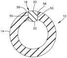
Figure 4 is a cross-sectional view taken along the cross-section indicated by line 4-4 in Figure 1.
Figure 5 is a cross-sectional view of a prior art grip with inlaid ribs assembled on a club shaft.
도 1을 참조하면, 골프 클럽용의 완성된 가요성 그립의 사시도가 대체적으로 10으로 도시되어 있으며, 실질적으로 폐쇄된 단부(12) 및 파선으로 표시된 개방 단부(16)를 갖는 튜브형 본체(14)를 가지며, 상기 개방 단부 내에 클럽 샤프트(17)의 단부가 수용되어 있다. 대체적으로 18로 표시된 긴 삽입체가 성형 동안에 그립 내에 형성되며, 이는 이하에서 더 상세히 설명되는 바와 같다.1 , a perspective view of a completed flexible grip for a golf club is shown generally at 10, comprising a
도 4를 참조하면, 본 발명의 골프 그립의 한 가지 형태가 클럽 샤프트에 조립된 바와 같이 단면으로 도시되어 있으며, 이때 삽입체(18)는 튜브형 그립 본체(14)의 벽 두께를 통해 그의 내부로부터 외부로 완전히 연장되는 것으로 도시되어 있다. 삽입체의 외부 표면은 융기형 리브 구성을 제공하도록 약간 변형되었다. 본 실시에서, 리브(18)의 외부 표면(20)은 튜브형 본체(14)의 외부 표면으로부터 약 1 mm만큼 외향으로 연장될 수 있다. 이는 클럽 샤프트(17) 위에서 조립할 때 삽입체의 내부 표면의 휨 또는 변형에 의해 달성된다.4, one version of the golf grip of the present invention is shown in cross section as assembled to a club shaft, with the
도 2 및 도 3을 참조하면, 압축 주형(30)의 상부 섹션이 도 3에 "PL"로 표시된 분할선을 따라 하부 섹션(32) 상에 조립된 것으로 도시되어 있다. 주형의 상부 섹션(30)은 그에 형성된 주형 공동(34)을 가지며, 상기 주형 공동은 그립 본체(14)의 외부 표면에 그래픽 디자인 또는 질감을 제공하도록 구성된 표면을 가질 수 있다. 주형(32)의 하부 섹션은, 또한 그립 본체(14)의 외부 표면에 그래픽 디자인 또는 질감을 제공하도록 구성될 수 있는 대응하는 주형 공동(36)을 가지며; 공동(36)은 그 안에서 그의 바닥에 형성된 이격된 리지들(38, 39)을 형성하고, 상기 이격된 리지들 사이에 탄성중합체 삽입체(18)의 외부 표면(20)이 배치되어 있다.2 and 3, the upper section of the
코어 바(40)가 공동들(34, 36) 내에서 중심에 배치되고; 코어 바(40)는 그 하부에 형성된 홈(41)을 가지며, 상기 홈은 그 안에 삽입체(18)의 내부 표면(22)을 수용하며 성형 중에 삽입체를 제 위치에 위치설정하여 유지하도록 돕는다.A core bar (40) is centrally disposed within the cavities (34, 36); The
상부 주형 섹션(30)은 삽입체(18)의 서로 반대편인 측면들 상에 각각 배치되는, 내부에 형성된 한 쌍의 하향으로 연장되는 성형 주둥이(42, 44)를 갖는다. 각각의 주둥이(42, 44)는 각자의 횡단 통로(46, 48)와 각각 연통하며, 이러한 횡단 통로들(46, 48)은 주형 공동들(34, 36)의 서로 반대편인 측면들과 연통한다. 본 실시에서, 코어 바(40) 및 삽입체(18)가 제 위치에 있는 상태에서, 탄성중합체 재료(도시되지 않음)가 주둥이들(42, 44) 및 통로들(46, 48)을 통해 주형 공동들(34, 36) 내로 하향으로 사출되고, 이들 공동을 충전하고, 탄성중합체 재료(도시되지 않음)는 성형 시에 삽입체(18)의 측면들(50, 52)에 접촉하여 접합된다. 대안적으로, 파선으로 된 외형선으로 도시된 단일 중심 성형 주둥이(54)가 상부 주형 섹션(30) 내에 제공되어 공동(34)의 상부 표면 내로 하향으로 탄성중합체의 사출 성형을 허용할 수 있어서, 탄성중합체가 코어 바 둘레에 그리고 삽입체(18)의 측면들(50, 52) 상으로 유동하게 한다.The
도 2를 참조하면, 내부에 삽입체(18)가 일체로 성형되어 있는 경화된 그립은, 보이는 바와 같이, 주형으로부터의 제거 및 코어 바의 제거 시에 리브의 하부 표면(22)이 본체(14)의 내부 주연부 내로 약간 연장되는 것으로 도시되어 있다. 리브의 상부 표면(20)은 하부 주형 섹션(32) 내의 리지들(38, 39)에 의해 형성된 바와 같이 측면들(50, 52) 각각에 인접한 홈(56, 58)을 각각 갖는다.Referring to Figure 2, a hardened grip with an
따라서, 본 발명은 그립 본체보다 더 큰 강성을 갖는 탄성중합체 재료로 형성된 일체형 전체 두께 리브를 갖는 골프 클럽용의 독특한 가요성 그립을 기술한다. 삽입체는 그립의 벽 두께를 통해 완전히 연장되며, 사용자의 손에서의 그립의 배향을 용이하게 하고 파지성을 향상시키기 위해 삽입체의 상부 또는 외부 표면이 튜브형 그립의 외부에 노출되게 한다. 경화된 그립을 클럽 샤프트 상에 조립할 때, 삽입체의 상부 표면의 부분들은 약 1 mm의 양으로 외향으로 연장될 수 있다. 본 실시에서, 튜브형 본체(14)의 재료의 강성보다 적어도 10 퍼센트(10%) 더 큰 강성을 갖는 탄성중합체 재료의 삽입체(18)를 형성하는 것이 만족스러운 것으로 밝혀졌다. 증가된 강성은 또한 국부적으로 또는 전체적으로 섬유 보강에 의해 달성될 수 있다. 삽입체(18)는 또한 파지될 때 상이한 감촉 또는 촉지각(tactile perception)을 갖는 탄성중합체 재료로 형성될 수 있다. 이는 향상된 파지성을 위해 상이한 식별가능한 조도(roughness)를 표면에 부여하기 위해 재료에 유리 또는 모래와 같은 미립자 물질을 포함하게 함으로써 달성될 수 있다. 본 실시에서, 탄성중합체 리브는 쇼어 "A" 스케일에서 65 내지 80 범위의 듀로미터 경도를 갖고; 튜브형 그립의 본체의 재료는 쇼어 "A" 스케일에서 30 내지 60 범위의 경도를 갖는다. 본 발명의 방법의 실시에서, 삽입체는 코어 바를 갖는 주형 내로 조립되고, 탄성중합체 재료는 코어 바를 둘러싸는 주형 공동 내로 사출되며, 사출되는 탄성중합체는 성형 동안 삽입체의 측면들에 접합된다. 본 실시에서, 삽입체(18)는 사전 경화된 탄성중합체로 형성될 수 있고, 튜브형 그립의 본체의 재료와는 상이한 탄성중합체 재료로 형성될 수 있으며; 삽입체는 상이한 색상, 및 상이한 질감을 가질 수 있다.Accordingly, the present invention describes a unique flexible grip for a golf club having integral full thickness ribs formed of an elastomeric material having greater rigidity than the grip body. The insert extends fully through the wall thickness of the grip, leaving a top or outer surface of the insert exposed to the exterior of the tubular grip to facilitate orientation of the grip in the user's hand and improve gripping properties. When assembling the hardened grip onto a club shaft, portions of the upper surface of the insert may extend outward by an amount of approximately 1 mm. In this practice, it has been found satisfactory to form the
예시적인 실시예가 도면을 참조하여 설명되고 도시되었다. 명백하게, 전술한 상세한 설명을 읽고 이해할 때 다른 이들은 수정 및 변경을 할 것이다. 예시적인 실시예는 첨부된 청구범위 또는 그의 등가물의 범주 내에 있는 한 모든 그러한 변형 및 변경을 포함하는 것으로 해석되는 것으로 의도된다.Exemplary embodiments have been described and shown with reference to the drawings. Obviously, others will make modifications and changes upon reading and understanding the foregoing detailed description. The exemplary embodiments are intended to be construed to include all such modifications and changes as come within the scope of the appended claims or their equivalents.
Claims (16)
Translated fromKorean(a) 반경 방향으로의 적어도 상기 그립의 두께의 높이인 횡단 높이(transverse height)를 갖는 탄성중합체 재료의 긴 삽입체를 형성하는 단계;
(b) 상기 그립의 외부 및 주형 공동과 연통하는 적어도 하나의 주둥이(sprue)를 형성하기 위한 구성을 갖는 상기 공동 내에 코어 바(core bar)를 배치하며, (i) 상기 공동 및 (ii) 상기 코어 바 중 하나 내의 홈 내에, 그리고 상기 코어 바와 상기 공동 사이에 상기 삽입체를 배치하는 단계;
(c) 상기 적어도 하나의 주둥이를 통해 상기 공동 내로 그리고 상기 삽입체 주위에 탄성중합체를 사출하는 단계; 및
(d) 상기 성형된 그립을 상기 공동으로부터 제거하고 상기 코어 바를 상기 그립으로부터 제거하는 단계를 포함하며;
상기 공동 내에 리지들을 형성하고, 상기 코어 바 내에 홈을 형성하고, 상기 홈 내에 그리고 상기 리지들 사이에 상기 삽입체의 서로 반대편인 측면들을 배치하는 단계를 추가로 포함하는, 개선안.A method of manufacturing a tubular flexible grip for a golf club, comprising:
(a) forming an elongated insert of elastomeric material having a transverse height that is at least the height of the thickness of the grip in a radial direction;
(b) disposing a core bar within the cavity configured to form at least one sprue communicating with the exterior of the grip and the mold cavity, comprising: (i) the cavity and (ii) the mold cavity; positioning the insert within a groove in one of the core bars and between the core bar and the cavity;
(c) injecting elastomer through the at least one spout into the cavity and around the insert; and
(d) removing the molded grip from the cavity and removing the core bar from the grip;
The improvement further comprising forming ridges in the cavity, forming a groove in the core bar, and disposing opposing sides of the insert within the groove and between the ridges.
쇼어 "A" 스케일(Shore "A" scale)에서 30 내지 60 범위의 듀로미터 경도(durometer hardness)를 갖는 탄성중합체를 사출하는 단계를 추가로 포함하는, 개선안.According to paragraph 1,
An improvement, further comprising the step of injecting an elastomer having a durometer hardness ranging from 30 to 60 on the Shore "A" scale.
상기 삽입체의 서로 반대편인 측면들 상에 탄성중합체를 사출하는 단계를 추가로 포함하는, 개선안.According to paragraph 1,
An improvement, further comprising the step of injecting an elastomer on opposite sides of the insert.
(a) 실질적으로 폐쇄된 단부 및 개방 단부를 갖는 탄성중합체 재료로 형성되고 내부 표면이 상기 샤프트와 접촉하는 튜브형 부재;
(b) 상기 튜브형 부재 내에 배치되고 상기 튜브형 부재의 외부 표면에 노출된 제1 표면을 갖는 긴 삽입체를 포함하고, 상기 삽입체는 상기 튜브형 부재의 벽을 완전히 통과하여 내향으로 연장되어 상기 튜브형 부재의 내부 주연부에 노출된 상기 제1 표면의 반대편인 제2 표면을 가지며, 상기 튜브형 부재는 상기 삽입체의 양 측면 부근의 외부 표면에 형성된 홈을 갖는, 그립.A flexible tubular grip for receiving on the shaft of a golf club, comprising:
(a) a tubular member formed of an elastomeric material having a substantially closed end and an open end, the inner surface contacting the shaft;
(b) an elongated insert disposed within the tubular member and having a first surface exposed to an external surface of the tubular member, the insert extending inwardly completely through a wall of the tubular member; The grip has a second surface opposite the first surface exposed at an inner periphery of the insert, wherein the tubular member has grooves formed on the outer surface near both sides of the insert.
Applications Claiming Priority (2)
| Application Number | Priority Date | Filing Date | Title |
|---|---|---|---|
| US15/916,401US10293230B1 (en) | 2018-03-09 | 2018-03-09 | Flexible golf grip with full thickness rib section and method of making same |
| US15/916,401 | 2018-03-09 |
Publications (2)
| Publication Number | Publication Date |
|---|---|
| KR20190106797A KR20190106797A (en) | 2019-09-18 |
| KR102629317B1true KR102629317B1 (en) | 2024-01-24 |
Family
ID=65817735
Family Applications (1)
| Application Number | Title | Priority Date | Filing Date |
|---|---|---|---|
| KR1020190026520AActiveKR102629317B1 (en) | 2018-03-09 | 2019-03-07 | Flexible golf grip with full thickness rib section and method of making same |
Country Status (4)
| Country | Link |
|---|---|
| US (2) | US10293230B1 (en) |
| EP (1) | EP3536387B1 (en) |
| JP (1) | JP7541433B2 (en) |
| KR (1) | KR102629317B1 (en) |
Families Citing this family (5)
| Publication number | Priority date | Publication date | Assignee | Title |
|---|---|---|---|---|
| US10052538B2 (en) | 2016-09-20 | 2018-08-21 | Eaton Intelligent Power, Ltd. | Golf grip with reminder rib |
| KR102071332B1 (en)* | 2016-10-20 | 2020-01-30 | 김경호 | Grip for golf club |
| WO2021261732A1 (en)* | 2020-06-22 | 2021-12-30 | 김상훈 | Golf swing aiding mechanism |
| US11752410B2 (en) | 2021-09-28 | 2023-09-12 | Bradley R. Mason | Force sensor for alerting golfer when club held too tightly |
| US20230191212A1 (en)* | 2021-12-22 | 2023-06-22 | Eaton Intelligent Power Limited | Golf club grip with reminder rib |
Citations (4)
| Publication number | Priority date | Publication date | Assignee | Title |
|---|---|---|---|---|
| KR100221039B1 (en)* | 1990-12-30 | 1999-09-15 | 가다야마 유다까 | Golf club grip |
| JP2000263554A (en)* | 1999-03-19 | 2000-09-26 | Marugo Rubber Ind Co Ltd | Method for molding composite rubber molding |
| US20060287123A1 (en) | 2005-06-21 | 2006-12-21 | Jack Wang | Grip |
| JP2010264589A (en) | 2009-05-15 | 2010-11-25 | Eaton Corp | Lightweight hand grip and method for manufacturing the same |
Family Cites Families (19)
| Publication number | Priority date | Publication date | Assignee | Title |
|---|---|---|---|---|
| US3028283A (en)* | 1956-03-14 | 1962-04-03 | Macgregor Sport Products Inc | Method of making golf club grip |
| US3706453A (en)* | 1970-11-02 | 1972-12-19 | Northwestern Golf Co | Golf club with finger orienting grip |
| JPH03112576A (en)* | 1989-09-28 | 1991-05-14 | Kinugawa Rubber Ind Co Ltd | Golf grip made of synthetic resin |
| US5261665A (en)* | 1992-02-11 | 1993-11-16 | Robert A. Paley, Inc. | Golf club grip formed of a plurality of materials and method of manufacture thereof |
| US5897440A (en)* | 1997-09-05 | 1999-04-27 | Graman U.S.A., Inc. | Nodule golf shaft grip |
| JP4263792B2 (en)* | 1998-12-15 | 2009-05-13 | Sriスポーツ株式会社 | Golf club grip |
| JP2003180892A (en)* | 2001-10-10 | 2003-07-02 | Yuji Yoshiyasu | Grip for golf club |
| US20030228929A1 (en)* | 2002-06-11 | 2003-12-11 | Hiroshi Miyasu | Grip for golf club |
| TW588669U (en)* | 2002-08-07 | 2004-05-21 | Hong-Sung Chu | Handle of golf club with easily foldable structure |
| US6666777B1 (en)* | 2002-08-28 | 2003-12-23 | Lamkin Corp. | Partial cord golf grip and method of making same |
| US7749094B2 (en)* | 2003-12-29 | 2010-07-06 | Chen Yung Hsiang | Golf club grip and manufacturing method thereof |
| US7435186B1 (en)* | 2004-02-23 | 2008-10-14 | Miller R Lee | Golf club grip |
| JP4153924B2 (en)* | 2005-04-28 | 2008-09-24 | 株式会社ホンダアクセス | grip |
| US7458903B2 (en) | 2006-06-08 | 2008-12-02 | Eaton Corporation | Hand grip and method of making same |
| US7458902B2 (en) | 2007-03-14 | 2008-12-02 | Eaton Corporation | Changeable golf grip |
| US20110172024A1 (en)* | 2009-03-25 | 2011-07-14 | Lu Clive S | Grip for sporting equipment |
| US8485916B2 (en) | 2009-05-22 | 2013-07-16 | Eaton | Apparatus and method for forming a reminder rib in a grip |
| JP3155820U (en)* | 2009-09-18 | 2009-12-03 | チェン ユンシャンChen, Yung−Hsiang | Golf club grip with three-dimensional decoration design and molding die thereof |
| US20160271467A1 (en)* | 2015-01-19 | 2016-09-22 | Jbd Holdings Inc. | Texturized golf grip surfaces |
- 2018
- 2018-03-09USUS15/916,401patent/US10293230B1/enactiveActive
- 2019
- 2019-03-07KRKR1020190026520Apatent/KR102629317B1/enactiveActive
- 2019-03-08EPEP19161764.6Apatent/EP3536387B1/enactiveActive
- 2019-03-08JPJP2019042262Apatent/JP7541433B2/enactiveActive
- 2019-03-18USUS16/356,065patent/US10543411B2/enactiveActive
Patent Citations (4)
| Publication number | Priority date | Publication date | Assignee | Title |
|---|---|---|---|---|
| KR100221039B1 (en)* | 1990-12-30 | 1999-09-15 | 가다야마 유다까 | Golf club grip |
| JP2000263554A (en)* | 1999-03-19 | 2000-09-26 | Marugo Rubber Ind Co Ltd | Method for molding composite rubber molding |
| US20060287123A1 (en) | 2005-06-21 | 2006-12-21 | Jack Wang | Grip |
| JP2010264589A (en) | 2009-05-15 | 2010-11-25 | Eaton Corp | Lightweight hand grip and method for manufacturing the same |
Also Published As
| Publication number | Publication date |
|---|---|
| US10543411B2 (en) | 2020-01-28 |
| EP3536387B1 (en) | 2020-09-16 |
| JP7541433B2 (en) | 2024-08-28 |
| US10293230B1 (en) | 2019-05-21 |
| EP3536387A1 (en) | 2019-09-11 |
| KR20190106797A (en) | 2019-09-18 |
| US20190275395A1 (en) | 2019-09-12 |
| JP2019155098A (en) | 2019-09-19 |
Similar Documents
| Publication | Publication Date | Title |
|---|---|---|
| KR102629317B1 (en) | Flexible golf grip with full thickness rib section and method of making same | |
| AU2022259805B2 (en) | Golf grip with reminder rib | |
| KR101484511B1 (en) | Golf Club Grip | |
| US2604660A (en) | Mold and method for forming grips for golf clubs and the like | |
| US8485916B2 (en) | Apparatus and method for forming a reminder rib in a grip | |
| US6790401B2 (en) | Method for manufacturing a bowling pin | |
| US20200406113A1 (en) | Flexible grip with intermediate member | |
| CN204955269U (en) | There is not shrink trace injection moulding end cover part structure | |
| WO2022023395A1 (en) | A mold for injection molding | |
| US20180236698A1 (en) | Mold assembly for molding car door handle and method for molding car door handle using the assembly | |
| WO2005060726A1 (en) | Insert-molded synthetic resin spade and method of manufacturing the same | |
| CN209999609U (en) | beer sleeving plastic mold | |
| CN211758323U (en) | Pump cover sand core mold structure | |
| JP2652254B2 (en) | Manufacturing method of steering wheel | |
| CN105984058B (en) | Method for manufacturing multi-color handle of hand tool | |
| JPS60161123A (en) | Injection mold for tubular thick-walled resin molded piece | |
| JPH06305460A (en) | Structure and manufacture of rubber crawler | |
| JPH0651003B2 (en) | Molding method for multicolor soles with different colored tapes | |
| EP3028833A1 (en) | Handle and method, system and apparatus for manufacturing same | |
| JPH08310181A (en) | Barrel for writing implement or the like | |
| JP2006062111A (en) | Molding finishing method for resinous members | |
| JPH0721321U (en) | Injection mold | |
| JP2005169893A (en) | Injection molding mold | |
| JPH0122131B2 (en) | ||
| JPH0560819U (en) | Cap used for insert molding of bolts |
Legal Events
| Date | Code | Title | Description |
|---|---|---|---|
| PA0109 | Patent application | Patent event code:PA01091R01D Comment text:Patent Application Patent event date:20190307 | |
| PG1501 | Laying open of application | ||
| A201 | Request for examination | ||
| PA0201 | Request for examination | Patent event code:PA02012R01D Patent event date:20220307 Comment text:Request for Examination of Application Patent event code:PA02011R01I Patent event date:20190307 Comment text:Patent Application | |
| E902 | Notification of reason for refusal | ||
| PE0902 | Notice of grounds for rejection | Comment text:Notification of reason for refusal Patent event date:20230703 Patent event code:PE09021S01D | |
| E701 | Decision to grant or registration of patent right | ||
| PE0701 | Decision of registration | Patent event code:PE07011S01D Comment text:Decision to Grant Registration Patent event date:20231101 | |
| GRNT | Written decision to grant | ||
| PR0701 | Registration of establishment | Comment text:Registration of Establishment Patent event date:20240122 Patent event code:PR07011E01D | |
| PR1002 | Payment of registration fee | Payment date:20240122 End annual number:3 Start annual number:1 | |
| PG1601 | Publication of registration |