KR102629291B1 - An electronic device that uses a virtual field to reserve a transmission/reception time of a radar signal and control method thereof - Google Patents
An electronic device that uses a virtual field to reserve a transmission/reception time of a radar signal and control method thereofDownload PDFInfo
- Publication number
- KR102629291B1 KR102629291B1KR1020190118265AKR20190118265AKR102629291B1KR 102629291 B1KR102629291 B1KR 102629291B1KR 1020190118265 AKR1020190118265 AKR 1020190118265AKR 20190118265 AKR20190118265 AKR 20190118265AKR 102629291 B1KR102629291 B1KR 102629291B1
- Authority
- KR
- South Korea
- Prior art keywords
- signal
- electronic device
- present disclosure
- various embodiments
- fields
- Prior art date
- Legal status (The legal status is an assumption and is not a legal conclusion. Google has not performed a legal analysis and makes no representation as to the accuracy of the status listed.)
- Active
Links
Images


Classifications
- H—ELECTRICITY
- H04—ELECTRIC COMMUNICATION TECHNIQUE
- H04L—TRANSMISSION OF DIGITAL INFORMATION, e.g. TELEGRAPHIC COMMUNICATION
- H04L25/00—Baseband systems
- H04L25/02—Details ; arrangements for supplying electrical power along data transmission lines
- H04L25/0202—Channel estimation
- H04L25/0212—Channel estimation of impulse response
- H04L25/0216—Channel estimation of impulse response with estimation of channel length
- H—ELECTRICITY
- H04—ELECTRIC COMMUNICATION TECHNIQUE
- H04B—TRANSMISSION
- H04B7/00—Radio transmission systems, i.e. using radiation field
- H04B7/02—Diversity systems; Multi-antenna system, i.e. transmission or reception using multiple antennas
- H04B7/04—Diversity systems; Multi-antenna system, i.e. transmission or reception using multiple antennas using two or more spaced independent antennas
- H04B7/06—Diversity systems; Multi-antenna system, i.e. transmission or reception using multiple antennas using two or more spaced independent antennas at the transmitting station
- H04B7/0613—Diversity systems; Multi-antenna system, i.e. transmission or reception using multiple antennas using two or more spaced independent antennas at the transmitting station using simultaneous transmission
- H04B7/0615—Diversity systems; Multi-antenna system, i.e. transmission or reception using multiple antennas using two or more spaced independent antennas at the transmitting station using simultaneous transmission of weighted versions of same signal
- H04B7/0617—Diversity systems; Multi-antenna system, i.e. transmission or reception using multiple antennas using two or more spaced independent antennas at the transmitting station using simultaneous transmission of weighted versions of same signal for beam forming
- G—PHYSICS
- G01—MEASURING; TESTING
- G01S—RADIO DIRECTION-FINDING; RADIO NAVIGATION; DETERMINING DISTANCE OR VELOCITY BY USE OF RADIO WAVES; LOCATING OR PRESENCE-DETECTING BY USE OF THE REFLECTION OR RERADIATION OF RADIO WAVES; ANALOGOUS ARRANGEMENTS USING OTHER WAVES
- G01S7/00—Details of systems according to groups G01S13/00, G01S15/00, G01S17/00
- G01S7/003—Transmission of data between radar, sonar or lidar systems and remote stations
- G01S7/006—Transmission of data between radar, sonar or lidar systems and remote stations using shared front-end circuitry, e.g. antennas
- G—PHYSICS
- G01—MEASURING; TESTING
- G01S—RADIO DIRECTION-FINDING; RADIO NAVIGATION; DETERMINING DISTANCE OR VELOCITY BY USE OF RADIO WAVES; LOCATING OR PRESENCE-DETECTING BY USE OF THE REFLECTION OR RERADIATION OF RADIO WAVES; ANALOGOUS ARRANGEMENTS USING OTHER WAVES
- G01S7/00—Details of systems according to groups G01S13/00, G01S15/00, G01S17/00
- G01S7/02—Details of systems according to groups G01S13/00, G01S15/00, G01S17/00 of systems according to group G01S13/00
- G01S7/023—Interference mitigation, e.g. reducing or avoiding non-intentional interference with other HF-transmitters, base station transmitters for mobile communication or other radar systems, e.g. using electro-magnetic interference [EMI] reduction techniques
- G01S7/0235—Avoidance by time multiplex
- G—PHYSICS
- G01—MEASURING; TESTING
- G01S—RADIO DIRECTION-FINDING; RADIO NAVIGATION; DETERMINING DISTANCE OR VELOCITY BY USE OF RADIO WAVES; LOCATING OR PRESENCE-DETECTING BY USE OF THE REFLECTION OR RERADIATION OF RADIO WAVES; ANALOGOUS ARRANGEMENTS USING OTHER WAVES
- G01S7/00—Details of systems according to groups G01S13/00, G01S15/00, G01S17/00
- G01S7/02—Details of systems according to groups G01S13/00, G01S15/00, G01S17/00 of systems according to group G01S13/00
- G01S7/023—Interference mitigation, e.g. reducing or avoiding non-intentional interference with other HF-transmitters, base station transmitters for mobile communication or other radar systems, e.g. using electro-magnetic interference [EMI] reduction techniques
- G01S7/0236—Avoidance by space multiplex
- G—PHYSICS
- G01—MEASURING; TESTING
- G01S—RADIO DIRECTION-FINDING; RADIO NAVIGATION; DETERMINING DISTANCE OR VELOCITY BY USE OF RADIO WAVES; LOCATING OR PRESENCE-DETECTING BY USE OF THE REFLECTION OR RERADIATION OF RADIO WAVES; ANALOGOUS ARRANGEMENTS USING OTHER WAVES
- G01S7/00—Details of systems according to groups G01S13/00, G01S15/00, G01S17/00
- G01S7/02—Details of systems according to groups G01S13/00, G01S15/00, G01S17/00 of systems according to group G01S13/00
- G01S7/42—Diversity systems specially adapted for radar
- H—ELECTRICITY
- H04—ELECTRIC COMMUNICATION TECHNIQUE
- H04B—TRANSMISSION
- H04B1/00—Details of transmission systems, not covered by a single one of groups H04B3/00 - H04B13/00; Details of transmission systems not characterised by the medium used for transmission
- H04B1/38—Transceivers, i.e. devices in which transmitter and receiver form a structural unit and in which at least one part is used for functions of transmitting and receiving
- H04B1/40—Circuits
- H04B1/44—Transmit/receive switching
- H—ELECTRICITY
- H04—ELECTRIC COMMUNICATION TECHNIQUE
- H04B—TRANSMISSION
- H04B17/00—Monitoring; Testing
- H04B17/10—Monitoring; Testing of transmitters
- H04B17/101—Monitoring; Testing of transmitters for measurement of specific parameters of the transmitter or components thereof
- H—ELECTRICITY
- H04—ELECTRIC COMMUNICATION TECHNIQUE
- H04B—TRANSMISSION
- H04B7/00—Radio transmission systems, i.e. using radiation field
- H04B7/02—Diversity systems; Multi-antenna system, i.e. transmission or reception using multiple antennas
- H04B7/04—Diversity systems; Multi-antenna system, i.e. transmission or reception using multiple antennas using two or more spaced independent antennas
- H04B7/0413—MIMO systems
- H04B7/0417—Feedback systems
- H—ELECTRICITY
- H04—ELECTRIC COMMUNICATION TECHNIQUE
- H04B—TRANSMISSION
- H04B7/00—Radio transmission systems, i.e. using radiation field
- H04B7/02—Diversity systems; Multi-antenna system, i.e. transmission or reception using multiple antennas
- H04B7/04—Diversity systems; Multi-antenna system, i.e. transmission or reception using multiple antennas using two or more spaced independent antennas
- H04B7/06—Diversity systems; Multi-antenna system, i.e. transmission or reception using multiple antennas using two or more spaced independent antennas at the transmitting station
- H04B7/0613—Diversity systems; Multi-antenna system, i.e. transmission or reception using multiple antennas using two or more spaced independent antennas at the transmitting station using simultaneous transmission
- H04B7/0684—Diversity systems; Multi-antenna system, i.e. transmission or reception using multiple antennas using two or more spaced independent antennas at the transmitting station using simultaneous transmission using different training sequences per antenna
- H—ELECTRICITY
- H04—ELECTRIC COMMUNICATION TECHNIQUE
- H04B—TRANSMISSION
- H04B7/00—Radio transmission systems, i.e. using radiation field
- H04B7/02—Diversity systems; Multi-antenna system, i.e. transmission or reception using multiple antennas
- H04B7/04—Diversity systems; Multi-antenna system, i.e. transmission or reception using multiple antennas using two or more spaced independent antennas
- H04B7/08—Diversity systems; Multi-antenna system, i.e. transmission or reception using multiple antennas using two or more spaced independent antennas at the receiving station
- H04B7/0837—Diversity systems; Multi-antenna system, i.e. transmission or reception using multiple antennas using two or more spaced independent antennas at the receiving station using pre-detection combining
- H04B7/0842—Weighted combining
- H04B7/0848—Joint weighting
- H04B7/0851—Joint weighting using training sequences or error signal
- H—ELECTRICITY
- H04—ELECTRIC COMMUNICATION TECHNIQUE
- H04L—TRANSMISSION OF DIGITAL INFORMATION, e.g. TELEGRAPHIC COMMUNICATION
- H04L25/00—Baseband systems
- H04L25/02—Details ; arrangements for supplying electrical power along data transmission lines
- H04L25/0202—Channel estimation
- H04L25/0204—Channel estimation of multiple channels
- H—ELECTRICITY
- H04—ELECTRIC COMMUNICATION TECHNIQUE
- H04L—TRANSMISSION OF DIGITAL INFORMATION, e.g. TELEGRAPHIC COMMUNICATION
- H04L27/00—Modulated-carrier systems
- H04L27/26—Systems using multi-frequency codes
- H04L27/2601—Multicarrier modulation systems
- G—PHYSICS
- G01—MEASURING; TESTING
- G01S—RADIO DIRECTION-FINDING; RADIO NAVIGATION; DETERMINING DISTANCE OR VELOCITY BY USE OF RADIO WAVES; LOCATING OR PRESENCE-DETECTING BY USE OF THE REFLECTION OR RERADIATION OF RADIO WAVES; ANALOGOUS ARRANGEMENTS USING OTHER WAVES
- G01S13/00—Systems using the reflection or reradiation of radio waves, e.g. radar systems; Analogous systems using reflection or reradiation of waves whose nature or wavelength is irrelevant or unspecified
- G01S13/02—Systems using reflection of radio waves, e.g. primary radar systems; Analogous systems
- G01S13/06—Systems determining position data of a target
- G01S13/08—Systems for measuring distance only
- G01S13/32—Systems for measuring distance only using transmission of continuous waves, whether amplitude-, frequency-, or phase-modulated, or unmodulated
- G01S13/325—Systems for measuring distance only using transmission of continuous waves, whether amplitude-, frequency-, or phase-modulated, or unmodulated using transmission of coded signals, e.g. P.S.K. signals
- H—ELECTRICITY
- H04—ELECTRIC COMMUNICATION TECHNIQUE
- H04L—TRANSMISSION OF DIGITAL INFORMATION, e.g. TELEGRAPHIC COMMUNICATION
- H04L25/00—Baseband systems
- H04L25/02—Details ; arrangements for supplying electrical power along data transmission lines
- H04L25/0202—Channel estimation
- H04L25/0224—Channel estimation using sounding signals
- H—ELECTRICITY
- H04—ELECTRIC COMMUNICATION TECHNIQUE
- H04W—WIRELESS COMMUNICATION NETWORKS
- H04W84/00—Network topologies
- H04W84/02—Hierarchically pre-organised networks, e.g. paging networks, cellular networks, WLAN [Wireless Local Area Network] or WLL [Wireless Local Loop]
- H04W84/10—Small scale networks; Flat hierarchical networks
- H04W84/12—WLAN [Wireless Local Area Networks]
Landscapes
- Engineering & Computer Science (AREA)
- Computer Networks & Wireless Communication (AREA)
- Signal Processing (AREA)
- Radar, Positioning & Navigation (AREA)
- Remote Sensing (AREA)
- Physics & Mathematics (AREA)
- General Physics & Mathematics (AREA)
- Power Engineering (AREA)
- Electromagnetism (AREA)
- Radar Systems Or Details Thereof (AREA)
- Mobile Radio Communication Systems (AREA)
Abstract
Translated fromKoreanDescription
Translated fromKorean본 개시의 다양한 실시예들은, 가상의 필드를 이용하여 레이더 신호의 송수신 시간을 보유하는 전자 장치 및 그 제어 방법에 관한 것이다.Various embodiments of the present disclosure relate to an electronic device that maintains the transmission and reception time of a radar signal using a virtual field and a method of controlling the same.
전자 장치, 예를 들어, 스마트 폰과 같은 휴대용 전자 장치를 통해 제공되는 다양한 서비스 및 부가 기능들이 점차 증가하고 있다. 이러한 전자 장치의 효용 가치를 높이고, 다양한 사용자들의 욕구를 만족시키기 위해서 통신 서비스 제공자 또는 전자 장치 제조사들은 다양한 기능들을 제공하고 다른 업체와의 차별화를 위해 전자 장치를 경쟁적으로 개발하고 있다. 이에 따라, 전자 장치를 통해서 제공되는 다양한 기능들도 점점 고도화 되고 있다.The variety of services and additional functions provided through electronic devices, for example, portable electronic devices such as smart phones, is gradually increasing. In order to increase the utility value of these electronic devices and satisfy the needs of various users, communication service providers or electronic device manufacturers are competitively developing electronic devices to provide various functions and differentiate themselves from other companies. Accordingly, various functions provided through electronic devices are becoming increasingly sophisticated.
전자 장치의 외부에 위치한 객체를 검출(예: 전자 장치와 객체와의 거리를 검출)하기 위한 레이더 기능과 데이터 통신을 모두 지원하는 전자 장치에 있어서, 레이더 기능에 의해 데이터 통신이 간섭을 받을 수 있다. 특정한 프레임(frame)을 정상적으로 수신하기 위해서는 프레임의 프리앰블(preamble) 부터 정상적으로 수신이 되어야 한다. 그러나, 레이더 기능을 수행하기 위한 신호(본 개시에서 간략히 "레이더 신호" 또는 "레이더 펄스"라는 용어로 언급될 수 있다)를 출력 또는 수신하는 시점에 외부 전자 장치(예: 기지국)으로부터 데이터 통신을 위한 프레임의 전송이 수행되면, 이 때 전송된 프레임은 정상적으로 수신되지 못 할 수 있다. 이와 같이, 정상적으로 수신되지 않은 프레임은 에러 프레임(erroneous frame) 전송으로 고려될 수 있다. 레이더 기능의 수행을 위하여 수시로 레이더 신호의 송수신이 수행되는 경우, 프레임 에러 레이트(frame error rate)가 높아질 수 있으며, 이에 따라 전송률(transmission rate)이 감소할 수 있다. 결과적으로 전자 장치의 성능 저하가 발생될 수 있다.In electronic devices that support both radar functions for detecting objects located outside the electronic device (e.g., detecting the distance between the electronic device and the object) and data communication, data communication may be interfered with by the radar function. . In order to receive a specific frame normally, the preamble of the frame must be received normally. However, data communication is required from an external electronic device (e.g., a base station) at the time of output or reception of a signal for performing a radar function (which may be briefly referred to as a “radar signal” or “radar pulse” in this disclosure). When transmission of a frame is performed, the transmitted frame may not be received normally. In this way, frames that are not normally received may be considered as error frame transmission. When radar signals are frequently transmitted and received to perform the radar function, the frame error rate may increase, and the transmission rate may decrease accordingly. As a result, the performance of the electronic device may deteriorate.
본 개시의 다양한 실시예들에 따르면, 외부 전자 장치로 전송되는 신호에 지정된 필드(specified field)에 대한 정보를 포함시켜 전송함으로써 외부 전자 장치가 지정된 필드에 대한 수신 대기 상태를 유지할 수 있도록 하는 전자 장치 및 전자 장치의 동작 방법이 개시된다.According to various embodiments of the present disclosure, an electronic device that includes information about a specified field in a signal transmitted to an external electronic device and transmits it so that the external electronic device can maintain a waiting state for reception of the specified field. and a method of operating an electronic device are disclosed.
본 개시의 다양한 실시예들에 따르면, 외부 전자 장치가 지정된 필드에 대한 수신 대기 상태를 유지하는 동안에 레이더 신호를 송수신함으로써, 전자 장치의 성능 저하 없이 데이터 신호의 송수신과 레이더 신호의 송수신을 함께 수행할 수 있는 전자 장치 및 전자 장치의 동작 방법이 개시된다.According to various embodiments of the present disclosure, by transmitting and receiving radar signals while an external electronic device maintains a reception standby state for a designated field, transmission and reception of data signals and radar signals can be performed simultaneously without deteriorating the performance of the electronic device. An electronic device and a method of operating the electronic device are disclosed.
본 개시의 다양한 실시예들에 따른 전자 장치는, 통신 회로, 및 적어도 하나의 프로세서를 포함하고, 상기 적어도 하나의 프로세서는, 제1 신호를 출력하고 상기 제1 신호가 외부 객체에 의하여 반사된 반사 신호를 수신하기 위한 시간을 보유(reserve)하기 위한, 지정된 필드(specified field)의 수를 결정하고, 상기 지정된 필드의 수에 대한 정보를 포함하는 제2 신호를 생성하고, 상기 생성된 제2 신호를 외부 전자 장치로 전송한 후, 상기 통신 회로를 통해, 상기 제1 신호를 출력하고 상기 반사 신호를 수신하도록 설정될 수 있다.An electronic device according to various embodiments of the present disclosure includes a communication circuit and at least one processor, wherein the at least one processor outputs a first signal and the first signal is reflected by an external object. Determining the number of specified fields to reserve time for receiving a signal, generating a second signal including information about the number of specified fields, and generating the generated second signal After transmitting to an external electronic device, the first signal can be output and the reflected signal can be received through the communication circuit.
본 개시의 다양한 실시예들에 따른 전자 장치는, 통신 회로, 및 적어도 하나의 프로세서를 포함하고, 상기 적어도 하나의 프로세서는, 빔 포밍 트레이닝의 수행 여부를 판단하고, 상기 빔 포밍 트레이닝이 수행되지 않을 것으로 판단된 경우, 지정된 필드의 수를 제1 방식(scheme)에 따라 결정하고, 상기 빔 포밍 트레이닝이 수행되어야 하는 것으로 판단된 경우, 상기 지정된 필드의 수를 상기 제1 방식과는 상이한 제2 방식에 따라 결정하도록 설정될 수 있다.An electronic device according to various embodiments of the present disclosure includes a communication circuit and at least one processor, wherein the at least one processor determines whether beam forming training is performed and determines whether the beam forming training is not performed. If it is determined that the number of designated fields is determined according to the first scheme, and if it is determined that the beam forming training should be performed, the number of designated fields is determined in a second scheme different from the first scheme. It can be set to decide according to.
본 개시의 다양한 실시예들에 따른 전자 장치는, 안테나 어레이, 및 적어도 하나의 프로세서를 포함하고, 상기 적어도 하나의 프로세서는, 출력될 신호가 제1 신호인 경우에는, 상기 안테나 어레이의 일부를 송신(Tx) 상태로 설정하고, 나머지 일부를 수신(Rx) 상태로 설정하고, 출력될 신호가 제2 신호인 경우에는, 상기 안테나 어레이의 전부를 송신(Tx) 상태로 설정하도록 설정될 수 있다.An electronic device according to various embodiments of the present disclosure includes an antenna array and at least one processor, wherein the at least one processor transmits a portion of the antenna array when a signal to be output is a first signal. (Tx) state, the remaining part is set to receive (Rx) state, and when the signal to be output is the second signal, the entire antenna array can be set to be set to transmit (Tx) state.
본 개시의 다양한 실시예들에 따르면, 전자 장치는 외부 전자 장치로 전송하는 신호에 지정된 필드에 대한 정보를 포함시켜 전송함으로써 외부 전자 장치가 지정된 필드에 대한 수신 대기 상태를 유지하도록 할 수 있다.According to various embodiments of the present disclosure, an electronic device can transmit information about a specified field by including information about a specified field in a signal transmitted to an external electronic device, thereby allowing the external electronic device to maintain a state waiting for reception of the specified field.
본 개시의 다양한 실시예들에 따르면, 전자 장치는 외부 전자 장치가 지정된 필드에 대한 수신 대기 상태를 유지하는 동안에 레이더 신호를 송수신함으로써, 전자 장치의 성능 저하 없이 데이터 신호의 송수신과 레이더 신호의 송수신이 함께 수행 할 수 있다.According to various embodiments of the present disclosure, an electronic device transmits and receives radar signals while an external electronic device maintains a reception standby state for a designated field, thereby enabling transmission and reception of data signals and radar signals without deteriorating the performance of the electronic device. can be done together.
다양한 실시예들에 따른 효과는 상기 기술된 효과로 제한되지 아니하며, 다양한 효과가 본 개시 상에 내재되어 있음은 통상의 기술자에게 자명하다.Effects according to various embodiments are not limited to the effects described above, and it is obvious to those skilled in the art that various effects are inherent in the present disclosure.
도 1은, 다양한 실시예들에 따른, 네트워크 환경 내의 전자 장치의 블록도이다.
도 2는, 데이터 통신의 수행 중에 레이더 기능을 수행하는 경우의 문제점을 설명하기 위한 예시 도면이다.
도 3a는, 본 개시의 다양한 실시예들에 따른 송신 장치 및 수신 장치를 설명하기 위한 예시 도면이다.
도 3b는, 본 개시의 다양한 실시예들에 따른 골레이(golay) 시퀀스를 설명하기 위한 예시 도면이다.
도 3c 및 도 3d는, 본 개시의 다양한 실시예들에 따른 골레이 시퀀스(예: Ga128, Gb128)의 자기 상관(auto-correlation) 결과를 설명하기 위한 예시 도면이다.
도 3e는, 본 개시의 다양한 실시예들에 따른 골레이 시퀀스(예: Ga128, Gb128)의 자기상관 결과의 합을 설명하기 위한 예시 도면이다.
도 4는, 본 개시의 다양한 실시예들에 따른 채널 추정 방법을 설명하기 위한 예시 도면이다.
도 5는, 본 개시의 다양한 실시예들에 따른 PPDU(PHY protocol data unit)를 설명하기 위한 예시 도면이다.
도 6은, 본 개시의 다양한 실시예들에 따른 빔 포밍 트레이닝 프로세스를 설명하기 위한 예시 도면이다.
도 7은, 본 개시의 다양한 실시예들에 따른 트레이닝(TRN) 필드를 설명하기 위한 예시 도면이다.
도 8은, 본 개시의 다양한 실시예들에 따른 TRN 필드에 포함되는 정보를 설명하기 위한 예시 도면이다.
도 9는, 본 개시의 다양한 실시예들에 따른 전자 장치가 레이더 기능을 수행하는 동작 원리를 설명하기 위한 예시 도면이다.
도 10a 및 도 10b는, 본 개시의 다양한 실시예들에 따른 전자 장치의 동작 방법을 설명하기 위한 예시 도면이다.
도 11a 및 도 11b는, 본 개시의 다양한 실시예들에 따른 전자 장치에 의해 생성된 제2 신호를 설명하기 위한 예시 도면이다.
도 12는, 본 개시의 다양한 실시예들에 따라 레이더 신호가 송수신되는 동작을 설명하기 위한 예시 도면이다.
도 13a 및 도 13b는, 제2 신호의 길이가 임계 길이를 초과하는 경우, 본 개시의 다양한 실시예들에 따라 연산된 TRN 필드의 수에 대한 정보를 제2 신호의 출력 후에 출력되는 제3 신호에 포함하여 외부 전자 장치로 전송하는 동작을 설명하기 위한 예시 도면이다.
도 14는, 본 개시의 다양한 실시예들에 따른 전자 장치가 어플리케이션의 타입을 식별하고, 식별된 어플리케이션의 종류에 따라 전자 장치의 동작 모드를 상이하게 설정하는 동작을 설명하기 위한 예시 도면이다.
도 15 및 도 16은, 본 개시의 다양한 실시예들에 따른 전자 장치의 동작 방법을 설명하기 위한 예시 도면이다.
도 17은, 본 개시의 다양한 실시예들에 따른 안테나 동작 모드를 설명하기 위한 예시 도면이다.1 is a block diagram of an electronic device in a network environment, according to various embodiments.
Figure 2 is an example diagram to explain problems when performing a radar function while performing data communication.
FIG. 3A is an example diagram for explaining a transmitting device and a receiving device according to various embodiments of the present disclosure.
FIG. 3B is an example diagram for explaining a golay sequence according to various embodiments of the present disclosure.
FIGS. 3C and 3D are example diagrams for explaining auto-correlation results of Golay sequences (eg, Ga128, Gb128) according to various embodiments of the present disclosure.
FIG. 3E is an example diagram illustrating the sum of autocorrelation results of Golay sequences (eg, Ga128, Gb128) according to various embodiments of the present disclosure.
FIG. 4 is an example diagram for explaining a channel estimation method according to various embodiments of the present disclosure.
FIG. 5 is an example diagram for explaining a PHY protocol data unit (PPDU) according to various embodiments of the present disclosure.
FIG. 6 is an example diagram for explaining a beam forming training process according to various embodiments of the present disclosure.
FIG. 7 is an example diagram for explaining a training (TRN) field according to various embodiments of the present disclosure.
FIG. 8 is an example diagram illustrating information included in the TRN field according to various embodiments of the present disclosure.
FIG. 9 is an example diagram illustrating the operating principle of an electronic device performing a radar function according to various embodiments of the present disclosure.
10A and 10B are example diagrams for explaining a method of operating an electronic device according to various embodiments of the present disclosure.
FIGS. 11A and 11B are example diagrams for explaining a second signal generated by an electronic device according to various embodiments of the present disclosure.
FIG. 12 is an example diagram for explaining the operation of transmitting and receiving radar signals according to various embodiments of the present disclosure.
13A and 13B show, when the length of the second signal exceeds the threshold length, information about the number of TRN fields calculated according to various embodiments of the present disclosure as a third signal output after output of the second signal. This is an example diagram to explain the operation of transmitting to an external electronic device.
FIG. 14 is an example diagram illustrating an operation in which an electronic device identifies the type of an application and sets the operation mode of the electronic device differently depending on the type of the identified application, according to various embodiments of the present disclosure.
15 and 16 are example diagrams for explaining a method of operating an electronic device according to various embodiments of the present disclosure.
FIG. 17 is an example diagram for explaining antenna operation modes according to various embodiments of the present disclosure.
도 1은, 다양한 실시예들에 따른, 네트워크 환경(100) 내의 전자 장치(101)의 블록도이다.1 is a block diagram of an
도 1을 참조하면, 네트워크 환경(100)에서 전자 장치(101)는 제1 네트워크(198)(예: 근거리 무선 통신 네트워크)를 통하여 전자 장치(102)와 통신하거나, 또는 제2 네트워크(199)(예: 원거리 무선 통신 네트워크)를 통하여 전자 장치(104) 또는 서버(108)와 통신할 수 있다. 일 실시예에 따르면, 전자 장치(101)는 서버(108)를 통하여 전자 장치(104)와 통신할 수 있다. 일 실시예에 따르면, 전자 장치(101)는 프로세서(120), 메모리(130), 입력 장치(150), 음향출력장치(155), 표시 장치(160), 오디오 모듈(170), 센서 모듈(176), 인터페이스(177), 햅틱 모듈(179), 카메라 모듈(180), 전력 관리 모듈(188), 배터리(189), 통신 모듈(190), 가입자 식별 모듈(196), 또는 안테나 모듈(197)을 포함할 수 있다. 어떤 실시예에서는, 전자 장치(101)에는, 이 구성요소들 중 적어도 하나(예: 표시 장치(160) 또는 카메라 모듈(180))가 생략되거나, 하나 이상의 다른 구성 요소가 추가될 수 있다. 어떤 실시예에서는, 이 구성요소들 중 일부들은 하나의 통합된 회로로 구현될 수 있다. 예를 들어, 센서 모듈(176)(예: 지문 센서, 홍채 센서, 또는 조도 센서)은 표시 장치(160)(예: 디스플레이)에 임베디드 된 채 구현될 수 있다.Referring to FIG. 1, in the
프로세서(120)는, 예를 들어, 소프트웨어(예: 프로그램(140))를 실행하여 프로세서(120)에 연결된 전자 장치(101)의 적어도 하나의 다른 구성요소(예: 하드웨어 또는 소프트웨어 구성요소)를 제어할 수 있고, 다양한 데이터 처리 또는 연산을 수행할 수 있다. 일 실시예에 따르면, 데이터 처리 또는 연산의 적어도 일부로서, 프로세서(120)는 다른 구성요소(예: 센서 모듈(176) 또는 통신 모듈(190))로부터 수신된 명령 또는 데이터를 휘발성 메모리(132)에 로드하고, 휘발성 메모리(132)에 저장된 명령 또는 데이터를 처리하고, 결과 데이터를 비휘발성 메모리(134)에 저장할 수 있다. 일 실시예에 따르면, 프로세서(120)는 메인 프로세서(121)(예: 중앙 처리 장치 또는 어플리케이션 프로세서), 및 이와는 독립적으로 또는 함께 운영 가능한 보조프로세서(123)(예: 그래픽 처리장치, 이미지 시그널 프로세서, 센서허브 프로세서, 또는 커뮤니케이션 프로세서)를 포함할 수 있다. 추가적으로 또는 대체적으로, 보조 프로세서(123)는 메인 프로세서(121)보다 저전력을 사용하거나, 또는 지정된 기능에 특화되도록 설정될 수 있다. 보조 프로세서(123)는 메인 프로세서(121)와 별개로, 또는 그 일부로서 구현될 수 있다.
보조 프로세서(123)는, 예를 들어, 메인 프로세서(121)가 인액티브(예: 슬립) 상태에 있는 동안 메인 프로세서(121)를 대신하여, 또는 메인 프로세서(121)가 액티브(예: 어플리케이션 실행) 상태에 있는 동안 메인 프로세서(121)와 함께, 전자 장치(101)의 구성요소들 중 적어도 하나의 구성요소(예: 표시 장치(160), 센서 모듈(176), 또는 통신 모듈(190))와 관련된 기능 또는 상태들의 적어도 일부를 제어 할 수 있다. 일 실시예에 따르면, 보조프로세서(123)(예: 이미지 시그널 프로세서 또는 커뮤니케이션 프로세서)는 기능적으로 관련 있는 다른 구성요소(예: 카메라모듈(180) 또는 통신 모듈(190))의 일부로서 구현 될 수 있다.The
메모리(130)는, 전자 장치(101)의 적어도 하나의 구성요소(예: 프로세서(120) 또는 센서 모듈(176))에 의해 사용되는 다양한 데이터를 저장할 수 있다. 데이터는, 예를 들어, 소프트웨어(예: 프로그램(140)) 및, 이와 관련된 명령에 대한 입력 데이터 또는 출력 데이터를 포함할 수 있다. 메모리(130)는, 휘발성 메모리(132) 또는 비휘발성 메모리(134)를 포함 할 수 있다.The
프로그램(140)은 메모리(130)에 소프트웨어로서 저장될 수 있으며, 예를 들어, 운영 체제(142), 미들 웨어(144) 또는 어플리케이션(146)을 포함할 수 있다.The
입력 장치(150)는 전자 장치(101)의 구성 요소(예: 프로세서(120))에 사용될 명령 또는 데이터를 전자 장치(101)의 외부(예: 사용자)로부터 수신할 수 있다. 입력 장치(150)는, 예를 들어, 마이크, 마우스, 키보드 또는 펜 입력 장치(예: 스타일러스 펜)를 포함 할 수 있다.The
음향 출력 장치(155)는 음향 신호를 전자 장치(101)의 외부로 출력할 수 있다. 음향 출력 장치(155)는, 예를 들어, 스피커 또는 리시버를 포함할 수 있다. 스피커는 멀티미디어 재생 또는 녹음 재생과 같이 일반적인 용도로 사용될 수 있고, 리시버는 착신 전화를 수신 하기 위해 사용될 수 있다. 일 실시예에 따르면, 리시버는 스피커와 별개로, 또는 그 일부로서 구현 될 수 있다.The
표시 장치(160)는 전자 장치(101)의 외부(예: 사용자)로 정보를 시각적으로 제공 할 수 있다. 표시 장치(160)는, 예를 들어, 디스플레이, 홀로그램 장치, 또는 프로젝터 및 해당 장치를 제어하기 위한 제어 회로를 포함할 수 있다. 일 실시예에 따르면, 표시 장치(160)는 터치를 감지하도록 설정된 터치 회로(touch circuitry), 또는 상기 터치에 의해 발생되는 힘의 세기를 측정하도록 설정된 센서 회로(예: 압력 센서)를 포함할 수 있다.The
오디오 모듈(170)은 소리를 전기 신호로 변환시키거나, 반대로 전기 신호를 소리로 변환시킬 수 있다. 일 실시예에 따르면, 오디오 모듈(170)은, 입력 장치(150)를 통해 소리를 획득하거나, 음향 출력 장치(155), 또는 전자 장치(101)와 직접 또는 무선으로 연결된 외부 전자 장치(예: 전자 장치(102))(예: 스피커 또는 헤드폰)를 통해 소리를 출력할 수 있다.The
센서 모듈(176)은 전자 장치(101)의 작동 상태(예: 전력 또는 온도), 또는 외부의 환경 상태(예: 사용자 상태)를 감지하고, 감지된 상태에 대응하는 전기 신호 또는 데이터 값을 생성할 수 있다. 일 실시예에 따르면, 센서 모듈(176)은, 예를 들어, 제스처 센서, 자이로 센서, 기압 센서, 마그네틱 센서, 가속도 센서, 그립 센서, 근접 센서, 컬러 센서, IR(infrared) 센서, 생체 센서, 온도 센서, 습도 센서, 또는 조도 센서를 포함할 수 있다.The
인터페이스(177)는 전자 장치(101)가 외부 전자 장치(예: 전자 장치(102))와 직접 또는 무선으로 연결되기 위해 사용될 수 있는 하나 이상의 지정된 프로토콜들을 지원 할 수 있다. 일 실시예에 따르면, 인터페이스(177)는, 예를 들어, HDMI(high definition multimedia interface), USB(universal serial bus)인터페이스, SD카드 인터페이스, 또는 오디오 인터페이스를 포함할 수 있다.The interface 177 may support one or more designated protocols that can be used to connect the
연결 단자(178)는, 그를 통해서 전자 장치(101)가 외부 전자 장치(예: 전자장치(102))와 물리적으로 연결될 수 있는 커넥터를 포함할 수 있다. 일 실시예에 따르면, 연결 단자(178)는, 예를 들어, HDMI 커넥터, USB 커넥터, SD 카드 커넥터, 또는 오디오 커넥터(예: 헤드폰 커넥터)를 포함 할 수 있다.The
햅틱 모듈(179)은 전기적 신호를 사용자가 촉각 또는 운동 감각을 통해서 인지할 수 있는 기계적인 자극(예: 진동 또는 움직임) 또는 전기적인 자극으로 변환 할 수 있다. 일 실시예에 따르면, 햅틱 모듈(179)은, 예를 들어, 모터, 압전 소자, 또는 전기 자극 장치를 포함 할 수 있다.The
카메라 모듈(180)은 정지 영상 및 동영상을 촬영할 수 있다. 일 실시예에 따르면, 카메라 모듈(180)은 하나 이상의 렌즈들, 이미지 센서들, 이미지 시그널 프로세서들, 또는 플래시들을 포함할 수 있다.The
전력 관리 모듈(188)은 전자 장치(101)에 공급되는 전력을 관리할 수 있다. 일 실시예에 따르면, 전력 관리 모듈(188)은, 예를 들어, PMIC(power management integrated circuit)의 적어도 일부로서 구현 될 수 있다.The
배터리(189)는 전자 장치(101)의 적어도 하나의 구성 요소에 전력을 공급할 수 있다. 일 실시예에 따르면, 배터리(189)는, 예를 들어, 재충전 불가능한 1차 전지, 재충전 가능한 2차 전지 또는 연료 전지를 포함할 수 있다.The
통신 모듈(190)은 전자 장치(101)와 외부 전자 장치(예: 전자 장치(102)), 전자 장치(104), 또는 서버(108))간의 직접(예: 유선) 통신 채널 또는 무선 통신 채널의 수립, 및 수립된 통신 채널을 통한 통신 수행을 지원할 수 있다. 통신 모듈(190)은 프로세서(120)(예: 어플리케이션 프로세서)와 독립적으로 운영되고, 직접(예: 유선) 통신 또는 무선 통신을 지원하는 하나 이상의 커뮤니케이션 프로세서를 포함할 수 있다. 일 실시예에 따르면, 통신 모듈(190)은 무선 통신 모듈(192)(예: 셀룰러 통신 모듈, 근거리 무선 통신 모듈, 또는 GNSS(global navigation satellite system) 통신 모듈) 또는 유선 통신 모듈(194)(예: LAN(local area network) 통신 모듈, 또는 전력선 통신 모듈)을 포함할 수 있다. 이들 통신 모듈 중 해당하는 통신 모듈은 제1 네트워크(198)(예: 블루투스, WiFi direct 또는 IrDA(infrared data association) 같은 근거리 통신 네트워크) 또는 제2 네트워크(199)(예: 셀룰러 네트워크, 인터넷, 또는 컴퓨터 네트워크(예: LAN 또는 WAN)와 같은 원거리 통신 네트워크)를 통하여 외부 전자 장치와 통신할 수 있다. 이런 여러 종류의 통신 모듈들은 하나의 구성 요소(예: 단일 칩)로 통합되거나, 또는 서로 별도의 복수의 구성 요소들(예: 복수 칩들)로 구현될 수 있다. 무선 통신 모듈(192)은 가입자 식별 모듈(196)에 저장된 가입자 정보(예: 국제 모바일 가입자 식별자(IMSI))를 이용하여 제1 네트워크(198) 또는 제2 네트워크(199)와 같은 통신 네트워크 내에서 전자 장치(101)를 확인 및 인증 할 수 있다.The
안테나 모듈(197)은 신호 또는 전력을 외부(예: 외부 전자 장치)로 송신하거나 외부로부터 수신할 수 있다. 일 실시예에 따르면, 안테나 모듈(197)은 서브스트레이트(예: PCB) 위에 형성된 도전체 또는 도전성 패턴으로 이루어진 방사체를 포함하는 하나 이상의 안테나들을 포함할 수 있다. 일 실시예에 따르면, 안테나 모듈(197)은 복수의 안테나들을 포함할 수 있다. 이런 경우, 제1 네트워크(198) 또는 제2 네트워크(199)와 같은 통신 네트워크에서 사용되는 통신 방식에 적합한 적어도 하나의 안테나가, 예를 들어, 통신 모듈(190)에 의하여 상기 복수의 안테나들로부터 선택될 수 있다. 신호 또는 전력은 상기 선택된 적어도 하나의 안테나를 통하여 통신 모듈(190)과 외부 전자 장치 간에 송신되거나 수신될 수 있다. 어떤 실시예에 따르면, 방사체 이외에 다른 부품(예: RFIC)이 추가로 안테나 모듈(197)의 일부로 형성될 수 있다.The
상기 구성요소들 중 적어도 일부는 주변 기기들간 통신 방식(예: 버스, GPIO(general purpose input and output), SPI(serial peripheral interface), 또는 MIPI(mobile industry processor interface))을 통해 서로 연결되고 신호(예: 명령 또는 데이터)를 상호간에 교환할 수 있다.At least some of the components are connected to each other through a communication method between peripheral devices (e.g., bus, general purpose input and output (GPIO), serial peripheral interface (SPI), or mobile industry processor interface (MIPI)) and signal ( (e.g. commands or data) can be exchanged with each other.
본 개시의 다양한 실시예들에 따르면, 명령 또는 데이터는 제2 네트워크(199)에 연결된 서버(108)를 통해서 전자 장치(101)와 외부의 전자 장치(104)간에 송신 또는 수신될 수 있다. 외부 전자 장치(102, 104) 각각은 전자 장치(101)와 동일한 또는 다른 종류의 장치일 수 있다. 일 실시예에 따르면, 전자 장치(101)에서 실행되는 동작들의 전부 또는 일부는 외부 전자 장치들(102, 104, 또는 108) 중 하나 이상의 외부 전자 장치들에서 실행될 수 있다. 예를 들어, 전자 장치(101)가 어떤 기능이나 서비스를 자동으로, 또는 사용자 또는 다른 장치로부터의 요청에 반응하여 수행해야 할 경우에, 전자 장치(101)는 기능 또는 서비스를 자체적으로 실행시키는 대신에 또는 추가적으로, 하나 이상의 외부 전자 장치들에게 그 기능 또는 그 서비스의 적어도 일부를 수행하라고 요청할 수 있다. 상기 요청을 수신한 하나 이상의 외부 전자 장치들은 요청된 기능 또는 서비스의 적어도 일부, 또는 상기 요청과 관련된 추가 기능 또는 서비스를 실행하고, 그 실행의 결과를 전자 장치(101)로 전달할 수 있다. 전자 장치(101)는 상기 결과를, 그대로 또는 추가적으로 처리하여, 상기 요청에 대한 응답의 적어도 일부로서 제공할 수 있다. 이를 위하여, 예를 들어, 클라우드 컴퓨팅, 분산 컴퓨팅, 또는 클라이언트-서버 컴퓨팅 기술이 이용될 수 있다.According to various embodiments of the present disclosure, commands or data may be transmitted or received between the
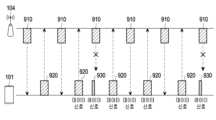
도 2는, 데이터 통신의 수행 중에 레이더 기능을 수행하는 경우의 문제점을 설명하기 위한 예시 도면이다. 도 2를 참조하면, 전자 장치(101)는 통신 모듈(190)을 통하여 외부 전자 장치(104)(예: 기지국)와 데이터 통신을 위한 신호(예: 수신 신호(910) 및 전송 신호(920))을 송신 또는 전송 할 수 있다. 전자 장치(101)에서 레이더 기능을 수행하기 위한 신호(930)를 출력 또는 수신하는 시점에 외부 전자 장치(104)(예: 기지국)으로부터 데이터 통신을 위한 수신 신호(910)의 전송이 수행되면, 이 때 전송된 수신 신호(910)는 전자 장치(101)에서 정상적으로 수신되지 못할 수 있다.Figure 2 is an example diagram to explain problems when performing a radar function while performing data communication. Referring to FIG. 2, the
도 3a는, 본 개시의 다양한 실시예들에 따른 송신 장치(200) 및 수신 장치(210)를 설명하기 위한 예시 도면이다. 도 3b는, 본 개시의 다양한 실시예들에 따른 골레이(golay) 시퀀스를 설명하기 위한 예시 도면이다. 도 3c 및 도 3d는, 본 개시의 다양한 실시예들에 따른 골레이 시퀀스(예: Ga128, Gb128)의 자기상관(auto-correlation) 결과를 설명하기 위한 예시 도면이다. 도 3e는, 본 개시의 다양한 실시예들에 따른 골레이 시퀀스(예: Ga128, Gb128)의 자기상관 결과의 합을 설명하기 위한 예시 도면이다.FIG. 3A is an example diagram for explaining a
도 3a를 참조하면, 본 개시의 다양한 실시예들에 따른 송신 장치(200)는, 적어도 하나의 기지국을 포함할 수 있다. 본 개시의 다양한 실시예들에 따른 송신 장치(200)는 골레이 시퀀스 생성 모듈(202)을 포함할 수 있다. 본 개시의 다양한 실시예들에 따른 골레이 시퀀스 생성 모듈(202)은, 아래의 수학식 1을 이용하여 채널 추정을 위한 신호(예: 참조 신호)를 생성할 수 있다. 본 개시의 다양한 실시예들에 따른 골레이 시퀀스 생성 모듈(202)은, 재귀적 절차(recursive procedure)를 통하여 골레이 시퀀스를 생성할 수 있다. 본 개시의 다양한 실시예들에 따른 송신 장치(200)는, 골레이 시퀀스를 포함하는 신호를 수신 장치(210)로 전송할 수 있다. 본 개시의 다양한 실시예들에 따른 골레이 시퀀스는 참조 신호의 CEF(channel estimation field)에 포함될 수 있다.Referring to FIG. 3A, a transmitting
수학식 1에서, k=1,2,...N(정수)일 수 있고, 반복 횟수(iteration number)를 의미할 수 있다. n= 0, 1, ... 일 수 있다. 수학식 1에서, 및는 골레이 시퀀스를 생성하기 위한 시드(seed) 벡터를 의미할 수 있다. =으로서 여기에서, Pn은, {0,1,...N}의 어떤 순열을 의미할 수 있다. 예를 들어, 길이 128에 해당하는 골레이 시퀀스를 생성하고자 하는 경우,는 [1, 8, 2, 4, 16, 32, 64](k = 1,2,3,4,5,6,7)가 될 수 있고,는 [-1 -1 -1 -1 +1 -1 -1]이 될 수 있다. 수학식 1에서은 디랙(dirac) 델타 함수로서, n=0인 경우에 1의 값을 가지고, 그 외의 n에 대해서 0의 값을 가질 수 있다. 수학식 1에서, 및은 n < 0 및구간에서 0일 수 있다. 본 개시의 다양한 실시예들에 따른 송신 장치(200)는, 및를 이용하여 도 3b에 도시된 바와 같은 골레이 시퀀스를 생성할 수 있다. 및은 골레이 A 시퀀스 및 골레이 B 시퀀스 각각에 포함되는 성분들을 의미할 수 있다.In
본 개시의 다양한 실시예들에 따른 수신 장치(210)는, 적어도 하나의 단말(예: 전자 장치(101))을 포함할 수 있다. 본 개시의 다양한 실시예들에 따른 수신 장치(210)는, 골레이 상관 모듈(212)을 포함할 수 있다. 본 개시의 다양한 실시예들에 따른 골레이 상관 모듈(212)은, 송신 장치(200)로부터 전송된 신호에 포함된 골레이 시퀀스(예: 골레이 A 시퀀스)에 대한 자기 상관(auto-correlation)을 수행할 수 있다. 본 개시의 다양한 실시예들에 따른 자기 상관의 결과 값은, 골레이 A 시퀀스를 아래의 수학식 2와 같이 교차 상관(cross-correlation)하여 획득될 수 있다.The receiving
수학식 2에서,은 교차 상관의 결과, n= 0, 1, ...,는 골레이 A 시퀀스의 전과 후에 0을 128개씩 추가한 시퀀스,은 길이 128의 골레이 A 시퀀스를 의미할 수 있다. 도 3c에서는, 길이 128의 골레이 A 시퀀스에 대한 자기 상관 결과가 도시된다. 본 개시의 다양한 실시예들에 따른 골레이 상관 모듈(212)은, 송신 장치(200)로부터 전송된 신호에 포함된 골레이 시퀀스(예: 골레이 B 시퀀스)에 대한 자기 상관을 수행할 수 있다. 본 개시의 다양한 실시예들에 따른 자기 상관의 결과 값은, 골레이 B 시퀀스를 아래의 수학식 3과 같이 교차 상관하여 획득될 수 있다.In
수학식 3에서,은 교차 상관의 결과, n= 0, 1, ...,는 골레이 A 시퀀스의 전과 후에 0을 128개씩 추가한 시퀀스,은 길이 128의 골레이 B 시퀀스를 의미할 수 있다. 도 3d에서는, 길이 128의 골레이 B 시퀀스에 대한 자기 상관 결과가 도시된다. 본 개시의 다양한 실시예들에 따른 수신 장치(210)(예: 골레이 상관 모듈 (212))는, 골레이 A 시퀀스에 대한 자기 상관의 결과와 골레이 B 시퀀스에 대한 자기 상관의 결과의 합을 연산할 수 있다. 도 3e에서는 골레이 A 시퀀스에 대한 자기 상관의 결과와 골레이 B 시퀀스에 대한 자기 상관의 결과의 합이 예시적으로 도시된다. 본 개시의 다양한 실시예들에 따른 수신 장치(210)는, 상보적 쌍(complementary pair)의 관계인 골레이 A 시퀀스 및 골레이 B 시퀀스를 이용하여 채널 추정을 수행할 수 있다.In equation 3, is the result of cross-correlation, n= 0, 1, ... , is a sequence in which 128 zeros are added before and after the Golay A sequence, may mean a Golay B sequence with a length of 128. In Figure 3d, the autocorrelation results for a Golay B sequence of
도 4는, 본 개시의 다양한 실시예들에 따른 채널 추정 방법을 설명하기 위한 예시 도면이다.FIG. 4 is an example diagram for explaining a channel estimation method according to various embodiments of the present disclosure.
본 개시의 다양한 실시예들에 따른 전자 장치(101)는, 외부 전자 장치(104) 로부터 복수의 경로(path)(예: 제1 경로(410), 제2 경로(420), 제3 경로(430))를 통해 신호를 수신할 수 있다. 본 개시의 다양한 실시예들에 따른 전자 장치(101)는 복수의 경로들을 통해 수신된 신호에 포함된 골레이 시퀀스들에 대한 자기 상관 값의 합(예: 채널 임펄스 응답)을 연산할 수 있다. 본 개시의 다양한 실시예들에 따른 전자 장치(101)는, 골레이 시퀀스들에 대한 자기 상관 값의 합에 기반하여 신호가 전송된 경로를 추정할 수 있다. 본 개시의 다양한 실시예들에 따른 전자 장치(101)는, 채널 임펄스 응답의 크기가 가장 큰 경로를 제1 경로(410)로 추정할 수 있다. 본 개시의 다양한 실시예들에 따른 전자 장치(101)는, 채널 임펄스 응답의 크기가 두 번째로 큰 경로를 제2 경로(420)로 추정할 수 있다. 본 개시의 다양한 실시예들에 따른 전자 장치(101)는, 채널 임펄스 응답의 크기가 가장 작은 경로를 제3 경로(430)로 추정할 수 있다.The
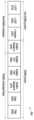
도 5는, 본 개시의 다양한 실시예들에 따른 PPDU(PHY protocol data unit)(500)를 설명하기 위한 예시 도면이다.FIG. 5 is an example diagram for explaining a PHY protocol data unit (PPDU) 500 according to various embodiments of the present disclosure.
본 개시의 다양한 실시예들에 따른 전자 장치(예: 도 1의 전자 장치(101))는, 외부 전자 장치(예: 도 1의 외부 전자 장치(104))로 PPDU 형식(format)의 신호를 출력할 수 있다. 본 개시의 다양한 실시예들에 따른 PPDU 형식(format)의 신호는, L-STF(legacy shot training field) (510), L-CEF(legacy channel estimation field) (520), L(legacy)-Header(530) 필드, EDMG(enhanced directional multi gigabit)-Header-A 필드(540), EDMG-STF(shot training field) (550), EDMG-CEF(channel estimation field)(560), EDMG-Header-B 필드(570), Data 필드(580) 및 TRN(training) 필드(590) 중 적어도 하나의 필드를 포함할 수 있다. 본 개시의 다양한 실시예들에 따른 적어도 하나의 필드는 PPDU의 형태(예: SU PPDU, MU PPDU)에 따라 선택적으로 PPDU에 포함될 수 있다. 본 개시의 다양한 실시예들에 따르면, L-STF 필드(510), L-CEF 필드(520) 및 L-Header(530) 필드를 포함하는 영역은 비 EDMG 부분(non-EDMG portion)이라고 언급될 수 있다. 본 개시의 다양한 실시예들에 따른 L-STF 필드(510), L-CEF 필드(520), L-Header(530) 필드 및 EDMG-Header-A 필드(540)는, pre-EDMG 변조 필드들(modulated fields)이라고 언급될 수 있다. 본 개시의 다양한 실시예들에 따른 EDMG-STF 필드(550), EDMG-CEF(560) 필드, EDMG-Header-B 필드(570), Data 필드(580) 및 TRN 필드(590)는, EDMG 변조 필드들이라고 언급될 수 있다. 본 개시의 다양한 실시예들에 따르면, 아래의 표 1과 같이 각각의 필드가 기술(description)될 수 있다.An electronic device (e.g., the
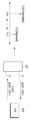
도 6은, 본 개시의 다양한 실시예들에 따른 빔 포밍 트레이닝 프로세스를 설명하기 위한 예시 도면이다.FIG. 6 is an example diagram for explaining a beam forming training process according to various embodiments of the present disclosure.
본 개시의 다양한 실시예들에 따르면, A-BFT (association beamForming training) 할당 내 발생하는 빔 포밍 트레이닝에 있어서, AP 또는 PCP(personal basic service set central point/access point)/AP는 개시자(initiator)(610)가 될 수 있고, 비-AP 및 비-PCP/AP STA은 응답자(responder)(620)가 될 수 있다. 본 개시의 다양한 실시예들에 따르면, SP(service period) 할당 내 발생하는 빔 포밍 트레이닝에 있어서, SP의 소스(EDMG) STA은 개시자(610)가 될 수 있고, SP의 목적지 STA은 응답자(620)가 될 수 있다. 본 개시의 다양한 실시예들에 따르면, TXOP(transmission opportunity) 할당 내 빔 포밍 트레이닝에 있어서, TXOP 홀더(holder)는 개시자(610)가 될 수 있고, TXOP 응답자는 응답자(620)가 될 수 있다. 본 개시의 다양한 실시예들에 따른 개시자로부터 응답자로의 링크(link)는 개시자 링크(initiator link)라고 언급될 수 있다. 본 개시의 다양한 실시예들에 따른 응답자로부터 개시자로의 링크는 응답자 링크 (responder link)라고 언급될 수 있다.According to various embodiments of the present disclosure, in beamforming training that occurs within an association beamforming training (A-BFT) allocation, an AP or a personal basic service set central point/access point (PCP)/AP is an initiator. 610, and non-AP and non-PCP/AP STAs can be
본 개시의 다양한 실시예들에 따른 빔 포밍 트레이닝은 SLS(Sector Level Sweep)(630) 단계(phase)로부터 시작될 수 있다. 본 개시의 다양한 실시예들에 따른 SLS(630) 단계의 목적은 제어 PHY 레이트 또는 상위 MCS(modulation and coding scheme) 에서 복수의 STA들 사이의 통신을 가능하게 하는 것일 수 있다. 예를 들어, SLS(630) 단계는, 네트워크 노드들이 빔의 방향만을 변경하면서 동일한 정보를 포함하는 프레임을 연속적으로 송수신하고, 성공적으로 수신된 프레임들 중에서 수신 채널 링크의 성능을 나타내는 지표(예: SNR(signal to ratio), 또는 RSSI(received signal strength indicator))이 가장 좋은 빔 방향을 선택하는 빔 트레이닝 방식을 의미할 수 있다. 본 개시의 다양한 실시예들에 따르면, 개시자 또는 응답자의 요청이 있는 경우 SLS(630)에 이어 BRP(beam refinement protocol 또는 beam refinement phase)(640) 단계가 수행될 수 있다. 본 개시의 다양한 실시예들에 따른 BRP(640) 단계는 SLS(630) 단계 또는 다른 수단에 의해 결정된 빔 방향에서 데이터 전송율을 최대화할 수 있는 빔 방향을 세밀하게 조절하는 프로토콜을 의미할 수 있다. 본 개시의 다양한 실시예들에 따른 BRP(640) 단계는 필요에 따라 수행될 수 있다. 본 개시의 다양한 실시예들에 따르면, BRP 프로토콜을 위해 정의된, 빔 트레이닝 정보와 트레이닝 결과를 보고하는 정보를 포함하는 BRP 프레임을 이용하여 빔 훈련을 수행할 수 있다. 본 개시의 다양한 실시예들에 따른 SLS(630) 단계에서는, 개시자 링크를 트레이닝하기 위한 ISS(initiator sector sweep), 응답자 링크를 트레이닝하기 위한 RSS(responder sector sweep), SSW 피드백 및 SSW ACK 을 포함할 수 있다. 본 개시의 다양한 실시예들에 따르면, 개시자(610)는 ISS의 프레임들을 응답자에게 전송함으로써 SLS(630) 단계를 시작할 수 있다. 본 개시의 다양한 실시예들에 따른 응답자(620)는, ISS가 성공적으로 완료되기 전에 RSS의 프레임(들)의 전송을 시작하지 않을 수 있다. 본 개시의 다양한 실시예들에 따른 개시자(610)는 RSS 단계가 성공적으로 완료되기 전에 SSW 피드백을 시작하지 않을 수 있다. 본 개시의 다양한 실시예들에 따른 응답자(620)는 개시자(610)의 SSW 피드백의 성공적인 전송 완료 이후에 개시자(610)에 대한 SSW ACK의 전송을 시작할 수 있다. 본 개시의 다양한 실시예들에 따르면, SLS(630) 단계 동안 개시자(610)가 전송하는 빔 포밍 프레임은, 비콘 프레임, SSW 프레임 및 SSW 피드백 프레임을 포함할 수 있다. 본 개시의 다양한 실시예들에 따른 SLS(630) 단계 동안, 응답자(620)가 개시자(610)에게 전송하는 빔 포밍 프레임은 SSW 프레임 및 SSW-ACK 프레임을 포함할 수 있다. 본 개시의 다양한 실시예들에 따르면, SLS(630) 단계 동안 개시자(610) 및 응답자(620)가 각각 TXSS(transmit sector sweep)을 수행하는 경우, 개시자(610) 및 응답자(620)는 그들 자신의 전송 섹터를 보유(possess)하게 될 수 있다. 본 개시의 다양한 실시예들에 따르면, 개시자(610) 및 응답자(620)는, 섹터 스윕 동안 전송 전력을 변경하지 않을 수 있다. 본 개시의 다양한 실시예들에 따른 다양한 실시예들은, 밀리미터 웨이브(mmWave)를 이용하는 통신 디바이스에 적용될 수 있다. 본 개시의 다양한 실시예들에 따른 전자 장치(예: 도 1의 전자 장치(101))는, 802.11 ay, 802.11 ad 및/또는 802.11 aj 와 같은 통신 방식을 이용하는 전자 장치를 포함할 수 있다. 본 개시의 다양한 실시예들에 따른 전자 장치(예: 도 1의 전자 장치(101))는, 5G 또는 UWB(ultra wide band)와 같은 광대역을 기반으로 레이더 기능을 수행할 수 있는 통신 모듈을 가지는 디바이스를 포함할 수 있다. 또한, 본 개시의 다양한 실시예들에 따른 전자 장치(예: 도 1의 전자 장치(101))는, 자기 상관(auto-correlation) 또는 교차 상관(cross-correlation)의 특정 패턴에 대해서 검출이 가능한 코드가 삽입된 신호들을 이용하는 디바이스를 포함할 수 있다. 본 개시의 다양한 실시예들은, 빔 트레이닝 동작을 상호간에 수행할 수 있는 디바이스들에서도 수행될 수 있다.Beam forming training according to various embodiments of the present disclosure may start from the Sector Level Sweep (SLS) 630 phase. The purpose of the
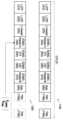
도 7은, 본 개시의 다양한 실시예들에 따른 트레이닝(TRN) 필드를 설명하기 위한 예시 도면이다. 도 8은, 본 개시의 다양한 실시예들에 따른 TRN 필드에 포함되는 정보를 설명하기 위한 예시 도면이다.FIG. 7 is an example diagram for explaining a training (TRN) field according to various embodiments of the present disclosure. FIG. 8 is an example diagram illustrating information included in the TRN field according to various embodiments of the present disclosure.
본 개시의 다양한 실시예들에 따른 PPDU(예: 도 5의 PPDU(500))는, 복수 개의 트레이닝 필드들(590a 내지 590j)을 포함할 수 있다. 본 개시의 다양한 실시예들에 따른 복수 개의 트레이닝 필드들(590a 내지 590j)은 TRN-Unit으로 구분될 수 있다. 본 개시의 다양한 실시예들에 따른 TRN-Unit은 5개의 TRN 필드(예: 트레이닝 필드들(590a 내지 590e))를 포함할 수 있으나, 이는 예시적인 것이다. 본 개시의 다양한 실시예들에 따른 TRN-Unit은 TRN-Unit P 필드 및 TRN-Unit M 필드를 포함할 수 있다. 본 개시의 다양한 실시예들에 따른 TRN-Unit P 필드는 2개의 트레이닝 필드들(예: 트레이닝 필드들(590a, 590b))을 포함할 수 있으나, 이는 예시적인 것이다. 본 개시의 다양한 실시예들에 따른 TRN-Unit M 필드는 3개의 트레이닝 필드들(예: 트레이닝 필드들(590c 내지 590e))을 포함할 수 있으나, 이는 예시적인 것이다. 본 개시의 다양한 실시예들에 따른 트레이닝 필드들(예: 트레이닝 필드들(590a 내지 590e))에는, 도 8에 도시된 바와 같이, 골레이 시퀀스에 대한 정보가 포함될 수 있다.A PPDU (eg,
도 9는, 본 개시의 다양한 실시예들에 따른 전자 장치가 레이더 기능을 수행하는 동작 원리를 설명하기 위한 예시 도면이다.FIG. 9 is an example diagram illustrating the operating principle of an electronic device performing a radar function according to various embodiments of the present disclosure.
도 9를 참조하면, 본 개시의 다양한 실시예들에 따른 전자 장치(101)는, 골레이 시퀀스를 포함하는 신호(예: 도 5의 PPDU(500))를 전자 장치(101)의 외부로 출력할 수 있다. 본 개시의 다양한 실시예들에 따른 골레이 시퀀스는 예를 들면, 채널 추정 필드(예: 도 5의 L-CEF 필드(520))에 포함될 수 있다. 본 개시의 다양한 실시예들에 따른 전자 장치(101)는, 객체(810)로부터 반사된 반사 신호를 수신할 수 있다. 본 개시의 다양한 실시예들에 따른 반사 신호는 τ시간만큼 지연된 신호일 수 있다. 본 개시의 다양한 실시예들에 따른 전자 장치(101)(예: 도 3a의 골레이 상관 모듈(212))는, 수신된 반사 신호에 대한 골레이 시퀀스의 자기 상관값(예: 채널 임펄스 응답)을 연산할 수 있다. 본 개시의 다양한 실시예들에 따른 전자 장치(101)(예: 도 3a의 골레이 상관 모듈(212))는, 수신된 반사 신호에 대한 골레이 시퀀스의 자기 상관값(예: 채널 임펄스 응답)을 연산하고, 신호가 출력되는 시점에서의 출력 신호에 대한 자기 상관 값의 피크 값과, 반사 신호에 대한 자기 상관 값의 피크 값을 비교함으로써, 지연 시간 τ를 식별(identify)할 수 있다. 본 개시의 다양한 실시예들에 따르면, 전자기파의 속도를라 할 때, 전자 장치(101)에서 송신한 신호가 객체(810)에 반사되어 수신이 되기까지 전자기파가 진행한 거리는가 될 수 있다. 본 개시의 다양한 실시예들에 따른값은, 객체(810)까지 왕복한 거리에 해당하므로, 객체(810)는 전자 장치(101)로부터거리에 떨어져 있다고 추정할 수 있다. 본 개시의 다양한 실시예들에 따르면, 전자 장치(101)는, 특정한 신호(예: 도 5의 PPDU(500))를 이용하여 객체(810)와의 거리를 식별할 수 있다. 본 개시에서, 설명의 편의를 위하여 객체(810)까지의 거리를 연산하는 기능 또는 동작 및, 제스처 또는 신체 일부(예: 얼굴)을 인식하는 기능 또는 동작은, "레이더 기능" 이라는 표현으로 간략히 언급될 수 있다. 본 개시의 다양한 실시예들에 따르면, 제1 신호(예: 레이더 신호)와 제2 신호(예: 데이터 송수신을 위한 신호)는 서로 동일한 주파수 대역(예: 6GHz 내지 300GHz 범위의 주파수 대역)에 포함되는 신호일 수 있다. 본 문서의 다양한 실시예들에 따르면, 제1 신호와 제2 신호는 서로 상이한 주파수 대역을 이용하여 송수신 될 수도 있다. 본 개시의 다양한 실시예들에 따른 제1 신호는, EDMG-STF 또는 EDMG-CEF 중 적어도 하나의 필드를 포함할 수 있다.Referring to FIG. 9, the
도 10a 내지 도 10b는, 본 개시의 다양한 실시예들에 따른 전자 장치의 동작 방법을 설명하기 위한 예시 도면이다.10A to 10B are example diagrams for explaining a method of operating an electronic device according to various embodiments of the present disclosure.
도 10a를 참조하면, 본 개시의 다양한 실시예들에 따른 전자 장치(101)는, 동작 1005에서 제1 데이터 신호를 외부 전자 장치(104)와 송수신할 수 있다. 본 개시의 다양한 실시예들에 따른 제1 데이터 신호는, 특정한 시간에 송수신되는 데이터 신호(예: 도 12의 데이터 수신 신호(910) 및 전송 신호(920))를 포함할 수 있다. 본 개시의 다양한 실시예들에 따른 "특정한 시간"은, 예를 들어, 전자 장치(101)가 외부 전자 장치(104)와 송수신할 수 있도록 보유된(reserved) 시간을 포함할 수 있다.Referring to FIG. 10A , the
본 개시의 다양한 실시예들에 따른 전자 장치(101)는, 동작 1010에서, 미리 지정된 주기 또는 지정된 조건(예: 레이더 신호의 송수신과 관련된 어플리케이션 실행)에 따라 트레이닝 필드(예: 도 5의 트레이닝 필드(590))의 수를 결정할 수 있다. 본 개시의 다양한 실시예들에 따른 전자 장치(101)는, 아래의 수학식 4를 이용하여 트레이닝 필드의 수를 결정할 수 있다. 본 개시에서, 수학식 4에 의하여 트레이닝 필드의 수를 결정하는 방식은 제1 방식이라고 언급될 수 있다. 보다 구체적으로, 본 개시의 다양한 실시예들에 따른 전자 장치(101)는, 제1 신호의 송수신 시간을 보유하기 위해서 빔 트레이닝을 수행하는 시간을 제1 신호의 송수신 시간으로 활용할 수 있다. 이를 위하여, 본 개시의 다양한 실시예들에 따른 전자 장치(101)는, 트레이닝 필드(예: 도 2의 트레이닝 필드(590))의 수에 대응하는 시간을 제1 신호의 송수신 시간으로 설정할 수 있다. 본 개시의 다양한 실시예들에 따른 전자 장치(101)는, 수학식 4에 따라 결정된 트레이닝 필드의 수를 헤더(예: 도 5의 EDMG Header-A 필드(540) 또는 EDMG Header-B 필드(570))에는 포함시킬 수 있지만, 실제로 외부 전자 장치(104)로 전송하지는 않을 수 있다. 본 개시의 다양한 실시예들에 따른 전자 장치(101)는 제1 신호를 송수신하는 시간을 확보하기 위하여 트레이닝 필드의 수를 결정할 수 있다.In operation 1010, the
수학식 4에서,는, 레이더 신호의 송수신에 필요한 시간을 의미할 수 있다. 본 개시의 다양한 실시예들에 따른 Tradar는 예를 들어, 727ns(nano second)일 수 있으나, 이는 예시적인 것이다. 본 개시의 다양한 실시예들에 따른의 값은 미리 정해질 수 있다. 수학식 4에서은 TRN 유닛의 듀레이션을 의미할 수 있다. 수학식 4에서 []는, 세일링(ceiling) 연산을 의미할 수 있으며, 예를 들어 [x]는, x보다 큰 최소의 정수를 의미할 수 있다. 본 개시의 다양한 실시예들에 따르면 TRN 유닛의 듀레이션은 아래의 수학식 5에 의하여 결정될 수 있다.In equation 4, may mean the time required for transmitting and receiving radar signals. Tradar according to various embodiments of the present disclosure may be, for example, 727 nano seconds (ns), but this is an example. According to various embodiments of the present disclosure The value of can be determined in advance. In equation 4: may mean the duration of the TRN unit. In Equation 4, [] may mean a sailing operation, and for example, [x] may mean the minimum integer greater than x. According to various embodiments of the present disclosure, the duration of the TRN unit can be determined by Equation 5 below.
또는, 본 개시의 다양한 실시예들에 따른 전자 장치(101)는 아래의 수학식 6을 이용하여 TRN 유닛의 듀레이션을 결정할 수 있다.Alternatively, the
수학식 6에서,는, 이하의 수학식 7에 의하여 결정될 수 있다. 수학식 6에서,는 0,1,2, 또는 4의 정수 값을 가질 수 있다. 수학식 6에서,은 1 내지 16의 정수값을 가질 수 있다. 수학식 6에서,는 이하의 수학식 8에 의하여 결정될 수 있다.In equation 6, Can be determined by Equation 7 below. In equation 6, can have integer values of 0, 1, 2, or 4. In equation 6, may have an integer value from 1 to 16. In equation 6, Can be determined by Equation 8 below.
수학식 7및 수학식 8에서, 은, PPDU의 전송에 사용되는 전송 체인들의 수에 따라 결정되는 파라미터로서, 1 내지 8의 정수 값을 가질 수 있다. 수학식 8에서, TRN_BL은, TRN 서브 필드에서 사용되는 골레이 시퀀스의 길이(예: 64, 128, 256)를 의미할 수 있다. 본 개시의 다양한 실시예들에 따르면, EDMG_TRN_LEN의 값은 외부 전자 장치(104)로부터 전송되거나, 또는 전자 장치(101)에 의해서 지정될 수 있다.In Equation 7 and Equation 8, is a parameter determined depending on the number of transmission chains used for transmission of the PPDU, and may have an integer value of 1 to 8. In Equation 8, TRN_BL may mean the length (e.g., 64, 128, 256) of the Golay sequence used in the TRN subfield. According to various embodiments of the present disclosure, the value of EDMG_TRN_LEN may be transmitted from the external
본 개시의 다양한 실시예들에 따른 전자 장치(101)는, 외부 전자 장치(104)로부터의 빔 트래킹(tracking) 요청에 따라 빔 포밍 트레이닝을 수행할 수 있다. 본 개시의 다양한 실시예들에 따른 전자 장치(101)는, 빔 트래킹 요청을 수신한 경우, 아래의 수학식 9에 따라 트레이닝 필드의 수를 결정할 수 있다. 본 개시에서, 수학식 9에 의하여 트레이닝 필드의 수를 결정하는 방식은 제2 방식이라고 언급될 수 있다.The
수학식 9에서,은 빔 포밍 트레이닝을 위해 필요한 트레이닝 필드의 수를 의미할 수 있다. 본 개시의 다양한 실시예들에 따른에 대한 정보는 외부 전자 장치(104)로부터 수신하거나 전자 장치(101)에 의하여 결정될 수 있다.In equation 9, may mean the number of training fields required for beam forming training. According to various embodiments of the present disclosure Information about may be received from the external
본 개시의 다양한 실시예들에 따른 전자 장치(101)는, 동작 1010과 관련하여, 다양한 방식에 따라 트레이닝 필드의 수를 결정할 수 있다. 예를 들어, 도 10b를 참조하면, 본 개시의 다양한 실시예들에 따른 전자 장치(101)는, 동작 1015에서, 빔 포밍 트레이닝의 수행 여부를 판단할 수 있다. 본 개시의 다양한 실시예들에 따른 전자 장치(101)는, 동작 1025에서, 빔 포밍 트레이닝이 수행되지 않을 것으로 판단된 경우, 지정된 필드(예: 트레이닝 필드)의 수를 제1 방식(scheme)에 따라 결정할 수 있다. 본 개시의 다양한 실시예들에 따른 전자 장치(101)는, 동작 1035에서, 빔 포밍 트레이닝이 수행될 것으로 판단된 경우, 지정된 필드(예: 트레이닝 필드)의 수를 제1 방식과는 상이한 제2 방식에 따라 결정할 수 있다.The
본 개시의 다양한 실시예들에 따른 전자 장치(101)는, 동작 1020에서 제2 신호를 생성할 수 있다. 본 개시의 다양한 실시예들에서 제2 신호는 데이터 전송을 위해 외부 전자 장치(104)로 전송되는 신호를 의미할 수 있다. 본 개시의 다양한 실시예들에 따른 전자 장치(101)는, 외부 전자 장치(104)로 출력될 헤더 필드(예: 도 5의 EDMG Header-A 필드(540) 또는 EDMG Header-B 필드(570))에, 결정된 트레이닝 필드의 수에 대한 정보를 포함시킴으로써 제2 신호를 생성할 수 있다. 본 개시의 다양한 실시예들에 따른 전자 장치(101)는, 제2 신호를 외부 전자 장치(104)로 전송할 경우, 빔 트래킹 요청에 따른 빔 포밍 트레이닝을 위한 필드만을 제2 신호에 추가(예: 삽입)하여 외부 전자 장치(104)로 전송할 수 있다. 다른 말로, 수학식 4에 따라 연산된 트레이닝 필드의 수에 따른 트레이닝 필드는 제2 신호에 실제로 추가되지 않을 수 있다. 본 개시에서, 실제로 제2 신호(예: 도 11a의 제2 신호(1100))에 추가되지 않는 트레이닝 필드는 "가상의 트레이닝 필드(virtual training field)"라는 용어로서 언급될 수 있다. 본 개시에서, "가상의 트레이닝 필드" 또는 "가상의 트레이닝 필드에 대한 정보"라는 용어는, "레이더 신호를 송수신할 시간 구간"과 같은 표현으로도 교환적으로/대체적으로 언급될 수 있다.The
본 개시의 다양한 실시예들에 따른 전자 장치(101)는, 동작 1030에서, 제2 신호를 외부 전자 장치(104)로 전송할 수 있다.The
본 개시의 다양한 실시예들에 따른 외부 전자 장치(104)는, 동작 1040에서, 제2 신호의 수신에 따라 트레이닝 필드의 수신 대기 상태로 진입할 수 있다. 본 개시의 다양한 실시예들에 따른 외부 전자 장치(104)는, 제2 신호(예: 도 5의 EDMG Header-A 필드(540) 또는 EDMG Header-B 필드(570)) 에 포함된 트레이닝 필드의 수에 대한 정보에 따라, 데이터 필드(예: 도 5의 데이터 필드(580))를 수신한 후, 트레이닝 필드의 수신 대기 상태로 진입할 수 있다.The external
본 개시의 다양한 실시예들에 따른 전자 장치(101)는, 동작 1050에서 제1 신호를 출력할 수 있다. 본 개시의 다양한 실시예들에 따른 제1 신호는 레이더 기능을 실행하기 위한 신호를 의미할 수 있다. 본 개시의 다양한 실시예들에 따른 제1 신호는 채널 추정 필드(예: 도 5의 L-CEF 필드(520))에 골레이 시퀀스에 대한 정보가 포함되고, 다른 적어도 하나의 필드에는 널(null) 데이터가 포함된 신호일 수 있다. 또는, 본 개시의 다양한 실시예들에 따른 제1 신호는, 골레이 시퀀스의 자기 상관 특성을 활용할 수 있는 다양한 구조들을 가질 수 있으며, 예를 들어, TRN 유닛이 제1 신호로서 사용될 수도 있다.The
본 개시의 다양한 실시예들에 따른 전자 장치(101)는, 동작 1060에서 제1 신호의 반사 신호를 수신할 수 있다. 본 개시의 다양한 실시예들에 따른 전자 장치(101)는, 동작 1070에서, 도 9에서 설명된 바와 같은 동작에 따라, 객체와의 거리를 검출할 수 있다.The
본 개시의 다양한 실시예들에 따른 전자 장치는, 동작 1080에서, 외부 전자 장치(140)와 제2 데이터 신호를 송수신할 수 있다. 본 개시의 다양한 실시예들에 따른 제2 데이터 신호는, 특정한 시간에 송수신되는 데이터 신호(예: 도 12의 수신 신호(910) 및 전송 신호(920))를 포함할 수 있다.The electronic device according to various embodiments of the present disclosure may transmit and receive a second data signal with the external
도 11a 내지 도 11c는, 본 개시의 다양한 실시예들에 따른 전자 장치에 의해 생성된 제2 신호를 설명하기 위한 예시 도면이다.11A to 11C are example diagrams for explaining a second signal generated by an electronic device according to various embodiments of the present disclosure.
도 11a를 참조하면, 본 개시의 다양한 실시예들에 따른 제1 방식에 따라 결정된 트레이닝 필드에 대한 정보는 외부 전자 장치(예: 도 1의 외부 전자 장치(104))로 전송될 신호의 헤더 필드(예: EDMG Header-A 필드(540) 또는 EDMG Header-B 필드(570))에 포함될 수 있다. 본 개시의 다양한 실시예들에 따르면, 제1 방식에 따라 결정된 트레이닝 필드의 수에 대응하는 트레이닝 필드(예: 트레이닝 필드(1190a) 내지 트레이닝 필드(1190b))는 제2 신호(1100)가 외부 전자 장치(예: 도 1의 외부 전자 장치(104))로 전송되는 경우, 제2 신호에 실제로 추가되지 않을 수 있다. 다른 말로, 제2 신호(1100)의 헤더 필드(예: EDMG Header-A 필드(540) 또는 EDMG Header-B 필드(570))에 트레이닝 필드에 대한 개수 정보만을 포함하고, 실제로는 제2 신호(1100)에 추가되지 않고 외부 전자 장치(104)로 전송될 수 있다. 이에 따라, 제2 신호(1100)를 수신한 외부 전자 장치(예: 도 1의 외부 전자 장치(104))는, 데이터 필드를 수신한 후, 트레이닝 필드의 수신 대기 상태로 전환(예: 진입)될 수 있다.Referring to FIG. 11A, information about the training field determined according to the first method according to various embodiments of the present disclosure is a header field of a signal to be transmitted to an external electronic device (e.g., the external
도 11b를 참조하면, 본 개시의 다양한 실시예들에 따른 제2 방식에 따라 결정된 트레이닝 필드에 대한 정보는 전자 장치로 전송될 신호의 헤더 필드(예: EDMG Header-A 필드(540) 또는 EDMG Header-B 필드(570))에 포함될 수 있다. 본 개시의 다양한 실시예들에 따르면, 제2 방식에 따라 결정된 트레이닝 필드의 수에 대응하는 트레이닝 필드 중 지정된 트레이닝 필드(예: 트레이닝 필드(1190c) 내지 트레이닝 필드(1190d))는 제2 신호(1100)가 외부 전자 장치(예: 도 1의 외부 전자 장치(104))로 전송되는 경우, 제2 신호에 실제로 추가되지 않을 수 있다. 본 개시의 다양한 실시예들에 따른 지정된 트레이닝 필드는 제1 방식에 따라 결정된 트레이닝 필드의 수에 대응하는 트레이닝 필드를 의미할 수 있다. 이에 따라, 제2 신호(1100)를 수신한 외부 전자 장치(예: 도 1의 외부 전자 장치(104))는, 빔 포밍 트레이닝을 실제로 수행하기 위해 요구되는 트레이닝 필드(예: 트레이닝 필드(1190a) 내지 트레이닝 필드(1190b))를 수신한 후, 지정된 시간(예: 트레이닝 필드(1190c) 내지 트레이닝 필드(1190d)를 위해 요구되는 시간)동안 트레이닝 필드의 수신 대기 상태로 전환(예: 진입)될 수 있다.Referring to FIG. 11B, information about the training field determined according to the second method according to various embodiments of the present disclosure is the header field (e.g., EDMG Header-
도 12는, 본 개시의 다양한 실시예들에 따라 레이더 신호가 송수신되는 동작을 설명하기 위한 예시 도면이다.FIG. 12 is an example diagram for explaining the operation of transmitting and receiving radar signals according to various embodiments of the present disclosure.
도 12를 참조하면, 본 개시의 다양한 실시예들에 따른 전자 장치(예: 도 1의 전자 장치(101))는 데이터 통신을 위해 송수신되는 데이터 신호(예: 수신 신호(910) 및 전송 신호(920))에 가상의 트레이닝 필드에 대한 정보(예: 레이더 시간을 송수신할 시간 구간에 대한 정보)를 추가하여 외부 전자 장치(예: 도 1의 외부 전자 장치(104))로 전송함으로써, 외부 전자 장치(예: 도 1의 외부 전자 장치(104))가 트레이닝 필드에 대한 수신 대기 상태로 전환하도록 할 수 있다. 본 개시의 다양한 실시예들에 따른 전자 장치(101)는, 외부 전자 장치(예: 도 1의 외부 전자 장치(104))가 트레이닝 필드의 수신 대기 상태인 동안에 레이더 신호를 송수신함으로써, 데이터 신호(예: 전송 신호(920)) 의 전송에 영향을 주지 않고 레이더 신호를 송수신 할 수 있다. 본 개시의 다양한 실시예들에 따른 레이더 신호(930)는, 외부 전자 장치(104)가 트레이닝 필드에 대한 수신 대기 상태인 동안에 송수신 될 수 있다.Referring to FIG. 12, an electronic device (e.g., the
도 13a 및 도 13b는, 제2 신호의 길이가 임계 길이를 초과하는 경우, 본 개시의 다양한 실시예들에 따라 연산된 트레이닝 필드의 수에 대한 정보를 제2 신호의 출력 후에 출력되는 제3 신호에 포함하여 외부 전자 장치로 전송하는 동작을 설명하기 위한 예시 도면이다.13A and 13B show, when the length of the second signal exceeds the threshold length, information about the number of training fields calculated according to various embodiments of the present disclosure as a third signal output after output of the second signal. This is an example diagram to explain the operation of transmitting to an external electronic device.
도 13a를 참조하면, 본 개시의 다양한 실시예들에 따른 전자 장치(예: 도 1의 전자 장치(101))는, 동작 1305에서, 빔 트래킹 요청을 수신할 수 있다. 본 개시의 다양한 실시예들에 따른 빔 트래킹 요청은 외부 전자 장치(예: 도 1의 외부 전자 장치(104))로부터 전송될 수 있다. 본 개시의 다양한 실시예들에 따르면, 전자 장치(101)는, 외부 전자 장치(예: 도 1의 외부 전자 장치(104))로부터의 빔 트래킹 요청이 없이 빔 트레이닝 시점을 판단하여 빔 트레이닝을 수행할 수도 있다. 이 경우, 본 개시의 다양한 실시예들에 따른 전자 장치(101)는, 빔 트레이닝 기능 또는 동작과, 레이더 기능 또는 동작을 동시에 수행할 수도 있다.Referring to FIG. 13A, an electronic device (e.g., the
본 개시의 다양한 실시예들에 따른 전자 장치(예: 도 1의 전자 장치(101))는, 동작 1315에서, 제2 신호(예: 도 11a의 제2 신호(1100))에 삽입될 트레이닝 필드를 식별할 수 있다. 본 개시의 다양한 실시예들에 따르면, 제2 신호(예: 도 11a의 제2 신호(1100))에 삽입될 트레이닝 필드의 수에 대한 정보(예:)는 외부 전자 장치(예: 도 1의 외부 전자 장치(104))로부터 전송될 수 있다. 본 개시의 다양한 실시예들에 따른 전자 장치(예: 도 1의 전자 장치(101))는, 제2 방식에 따라 제2 신호(예: 도 11a의 제2 신호(1100))에 삽입될 트레이닝 필드를 식별할 수 있다.An electronic device (e.g., the
본 개시의 다양한 실시예들에 따른 전자 장치(예: 도 1의 전자 장치(101))는, 동작 1325에서, 제2 신호(예: 도 11a의 제2 신호(1100))에 트레이닝 필드를 삽입할 수 있다.An electronic device (e.g., the
본 개시의 다양한 실시예들에 따른 전자 장치(예: 도 1의 전자 장치(101))는, 동작 1335에서, 트레이닝 필드의 삽입에 따라 제2 신호의 길이가 지정된 길이(예: 임계 길이)를 초과하는지 여부를 판단할 수 있다.In
본 개시의 다양한 실시예들에 따른 전자 장치(예: 도 1의 전자 장치(101))는, 동작 1345에서(동작 1335-예), 제1 신호를 송수신할 시간을 보유하기 위한 트레이닝 필드의 수에 대한 정보를 제3 신호에 포함하여 외부 전자 장치(예: 도 1의 외부 전자 장치(104))로 전송할 수 있다. 본 개시의 다양한 실시예들에 따른 제3 신호는, 제2 신호(예: 도 11a의 제2 신호(1100))의 전송 후에 제2 신호의 다음 신호(예: 프레임) 로서 외부 전자 장치(예: 도 1의 외부 전자 장치(104))로 전송되는 신호를 의미할 수 있다. 도 13b를 참조하면, 본 개시의 다양한 실시예들에 따른 트레이닝 필드(예: 트레이닝 필드(1190a), 트레이닝 필드(1190b))의 추가에 따라 적어도 하나의 가상의 트레이닝 필드가 제2 신호(1100)에 삽입되지 못할 수 있다. 이 경우, 본 개시의 다양한 실시예들에 따른 전자 장치(101)는, 제3 신호에 가상의 트레이닝 필드에 대한 정보를 포함시켜 외부 전자 장치(예: 도 1의 외부 전자 장치(104))로 제3 신호를 전송할 수 있다. 본 개시의 다양한 실시예들에 따른 전자 장치(예: 도 1의 전자 장치(101))는, 제3 신호를 전송 한 후 레이더 신호를 송수신할 수 있다.도 13a 및 도 13b에 도시된 실시예에 의할 경우, PPDU 길이 상의 제약에 따라 가상의 트레이닝 필드의 삽입이 어려운 경우에도, 레이터 신호의 송수신을 확보할 수 있는 효과가 발휘될 수 있다.An electronic device (e.g., the
본 개시의 다양한 실시예들에 따른 전자 장치(예: 도 1의 전자 장치(101))는, 동작 1355에서(동작 1335-아니오), 제1 신호를 송수신할 시간을 보유하기 위한 트레이닝 필드의 수에 대한 정보를 제2 신호(예: 도 11a의 제2 신호(1100))에 포함하여 외부 전자 장치(예: 도 1의 외부 전자 장치(104))로 전송할 수 있다.An electronic device (e.g., the
도 14는, 본 개시의 다양한 실시예들에 따른 전자 장치가 어플리케이션의 타입을 식별하고, 식별된 어플리케이션의 종류에 따라 전자 장치의 동작 모드를 상이하게 설정하는 동작을 설명하기 위한 예시 도면이다.FIG. 14 is an example diagram illustrating an operation in which an electronic device identifies the type of an application and sets the operation mode of the electronic device differently depending on the type of the identified application, according to various embodiments of the present disclosure.
도 14를 참조하면, 본 개시의 다양한 실시예들에 따른 전자 장치(예: 도 1의 전자 장치(101))는, 동작 1410에서, 현재 전자 장치에서 실행 중인 어플리케이션의 타입을 식별할 수 있다.Referring to FIG. 14, an electronic device (e.g., the
본 개시의 다양한 실시예들에 따른 전자 장치(예: 도 1의 전자 장치(101))는, 동작 1420에서, 식별된 어플리케이션 타입이 지정된 어플리케이션 타입인지 여부를 판단할 수 있다. 본 개시의 다양한 실시예들에 따른 지정된 어플리케이션은, 초고해상도 비디오 스트리밍 어플리케이션 또는 VR 어플리케이션과 같이 저 지연(low-latency)을 요구하는 어플리케이션을 포함할 수 있다. 본 개시의 다양한 실시예들에 따른 어플리케이션은, 레이더 기능 또는 동작이 사용되는 어플리케이션을 포함할 수 있다.An electronic device (e.g., the
본 개시의 다양한 실시예들에 따른 전자 장치(예: 도 1의 전자 장치(101))는, 동작 1430에서(동작 1420-예), 식별된 어플리케이션 타입이 지정된 어플리케이션 타입인 경우, 제1 동작 모드에 따라 데이터 송수신을 수행할 수 있다. 본 개시의 다양한 실시예들에 따른 제1 동작 모드는, 가상의 트레이닝 필드를 제2 신호(예: 도 5의 제2 신호(500))에 삽입하여 레이더 신호의 송수신을 위한 시간을 보유하는 동작 모드를 의미할 수 있다.An electronic device (e.g., the
본 개시의 다양한 실시예들에 따른 전자 장치(예: 도 1의 전자 장치(101))는, 동작 1440에서(동작 1420-아니오), 식별된 어플리케이션 타입이 지정된 어플리케이션 타입이 아닌 경우, 제2 동작 모드에 따라 데이터 송수신을 수행할 수 있다. 본 개시의 다양한 실시예들에 따른 제2 동작 모드는, 가상의 트레이닝 필드를 이용하지 않는 모드를 의미할 수 있다. 예를 들어, 제2 동작 모드는, 도 2에서 도시된 기술에 따라 레이더 기능 또는 동작을 수행하는 동작 모드를 의미할 수 있다. 예를 들어, 제2 동작 모드는, SSW(sector sweep) 또는 CTS(clear to send) 프레임을 포함하는 관리 프레임(management frame)을 사용하여 레이더 기능 또는 동작을 수행하는 시간을 보유하는 동작 모드를 의미할 수 있다.An electronic device (e.g., the
도 15 및 도 16은, 본 개시의 다양한 실시예들에 따른 전자 장치(101)의 동작 방법을 설명하기 위한 예시 도면이다.15 and 16 are example diagrams for explaining a method of operating the
도 15를 참조하면, 본 개시의 다양한 실시예들에 따른 전자 장치는, 동작 1510에서, 제1 신호(예: 레이더 신호)를 출력하고 제1 신호가 외부 객체에 의하여 반사된 반사 신호를 수신하기 위한 시간을 보유(reserve)하기 위한, 지정된 필드(specified field)의 수를 결정하는 동작을 포함할 수 있다.Referring to FIG. 15, in
본 개시의 다양한 실시예들에 따른 전자 장치는, 동작 1520에서, 지정된 필드의 수에 대한 정보를 포함하는 제2 신호(예: 도 5의 제2 신호(500))를 생성할 수 있다.In
본 개시의 다양한 실시예들에 따른 전자 장치는, 동작 1530에서, 생성된 제2 신호를 외부 전자 장치로 전송한 후, 제1 신호를 출력하고 반사 신호를 수신할 수 있다.In
도 16을 참조하면, 본 개시의 다양한 실시예들에 따른 전자 장치(101)는, 동작 1610에서, 출력될 신호의 속성을 판단할 수 있다.Referring to FIG. 16, the
본 개시의 다양한 실시예들에 따른 전자 장치(101)는, 동작 1620에서, 출력될 신호가 제1 신호인 경우에는, 안테나 어레이의 일부를 송신(Tx) 상태로 설정하고, 나머지 일부를 수신(Rx) 상태로 설정할 수 있다. 본 개시의 다양한 실시예들에 따른 안테나 어레이는 어레이 안테나를 포함할 수 있다. 또한, 본 개시의 다양한 실시예들에 따른 안테나 어레이는 적어도 하나의 패치 안테나 또는 적어도 하나의 다이폴 안테나(또는, 그 외의 안테나)를 포함할 수 있다. 본 개시의 다양한 실시예들에 따른 전자 장치(101)는, 제1 신호(예: 레이더 신호)를 출력하기 위하여 안테나 어레이의 일부 영역을 송신 상태로 설정할 수 있다. 본 개시의 다양한 실시예들에 따른 전자 장치(101)는 제1 신호가 반사된 신호를 수신하기 위하여 안테나 어레이의 나머지 일부를 수신(Rx) 상태로 설정할 수 있다.In
본 개시의 다양한 실시예들에 따른 전자 장치(101)는, 동작 1630에서, 출력될 신호가 제2 신호인 경우에는, 상기 안테나 어레이의 전부를 송신(Tx) 상태 또는 수신(Tx) 상태로 설정할 수 있다. 본 개시의 다양한 실시예들에 따른 제2 신호(예: 도 5의 제2 신호(500))는 외부 전자 장치(104)로 데이터를 송신하기 위한 신호를 포함할 수 있다.In
본 개시의 다양한 실시예들에 따른 전자 장치(101)는, 가상 현실을 제공하는 기기 또는 증강 현실을 제공하는 기기를 포함할 수 있다. 본 개시의 다양한 실시예들에 따른 전자 장치(101)는, 밀리미터 웨이브 통신 모듈을 포함할 수 있다. 본 개시의 다양한 실시예들에 따른 전자 장치(101)는, 외부 전자 장치(104)(예: 기지국)와 통신을 수행할 수 있다. 본 개시의 다양한 실시예들에 따른 전자 장치(101)는, 외부 전자 장치와 통신을 수행하는 중에, 카메라 또는 밀리미터 웨이브의 레이더 기능을 통하여 사용자의 제스처를 인식(예: 모니터링)할 수 있다. 본 개시의 다양한 실시예들에 따른 전자 장치(101)는, 밀리미터 웨이브를 이용한 통신 중에, 카메라를 통하여 사용자의 신체 일부(예: 손)의 움직임을 감지할 수 있다. 본 개시의 다양한 실시예들에 따른 전자 장치(101)는, 사용자의 신체 일부의 움직임이 감지된 경우 도면 10a에 도시된 동작을 통하여 사용자의 신체 일부의 움직임을 감지하기 위한 동작을 수행할 수 있다. 본 개시의 다양한 실시예들에 따른 전자 장치(101)는, 레이더 기능을 통하여 사용자의 신체 일부의 위치 또는 움직임을 감지할 수 있다. 본 개시의 다양한 실시예들에 따른 전자 장치(101)는, 가상 현실 화면 또는 증강 현실 화면 상의 특정한 위치에 사용자의 신체 일부가 위치된 경우, 특정한 위치를 기준으로 사용자의 신체 일부의 위치 또는 움직임을 추적 및/또는 감지할 수 있다. 본 개시의 다양한 실시예들에 따른 전자 장치(101)는, 미리 지정된 제스처가 감지되는 경우, 도면 10a에 도시된 동작을 통하여 사용자의 신체 일부의 움직임을 감지하기 위한 동작을 수행할 수 있다. 본 개시의 다양한 실시예들에 따른 전자 장치(101)는, 전자 장치(101)가 외부 전자 장치와 통신을 수행하는 중에 어플리케이션에서 특정한 제스처 동작 입력이 필요한 경우에도 도면 10a에 도시된 동작을 통하여 사용자의 신체 일부의 움직임을 감지하기 위한 동작을 수행할 수 있다. 본 개시의 다양한 실시예들에 따르면, 레이더 동작을 수행하는 어플리케이션과 데이터 통신을 수행하는 어플리케이션은 서로 동일한 어플리케이션일 수 있다.The
본 개시의 다양한 실시예들에 따른 전자 장치는, 레이더 기능을 위한 별도의 모듈(예: 칩 셋)을 더 포함할 수도 있다. 이 경우, 본 개시의 다양한 실시예들에 따른 전자 장치(101)는, 통신 기능과 레이더 기능을 배타적으로/병렬적으로(예: 동시에) 수행할 수 있다. 본 개시의 다양한 실시예들에 따르면, 각각의 모듈(예: 레이더 기능을 위한 모듈 및 데이터 통신 기능을 위한 모듈)과 프로세서(예: 도 1의 프로세서(120))는 각각 개별적인 데이터 경로를 통하여 연결될 수 있다. 본 개시의 다양한 실시예들에 따른 전자 장치(예: 데이터 통신 기능을 위한 모듈)은, 레이더 기능의 수행 시작 시점에서, 데이터 통신 기능을 위한 모듈을 이용하여, 통신을 수행하는 외부 전자 장치(예: 페어(pair) 디바이스)에 지정된 시간 동안 통신 수행을 중지하도록 지시하는 메시지를 전송할 수 있다. 예를 들어, 지정된 시간은 제1 방식에 따라 결정된 트레이닝 필드의 수에 대응하는 시간일 수 있다. 본 개시의 다양한 실시예들에 따르면, 지정된 시간은 프로세서(예: 도 1의 프로세서(120))에 의하여 지정된 값일 수도 있다. 본 개시의 다양한 실시예들에 따른 전자 장치(예: 레이터 기능을 위한 모듈)은, 지정된 시간 동안 레이더 기능을 수행할 수 있다. 본 개시의 다양한 실시예들에 따른 지정된 시간에 대한 정보는 각각의 모듈(예: 레이더 기능을 위한 모듈 및 데이터 통신 기능을 위한 모듈) 사이에서 공유될 수 있다.Electronic devices according to various embodiments of the present disclosure may further include a separate module (eg, chip set) for a radar function. In this case, the
본 개시의 다양한 실시예들에 따른 전자 장치(101)는, 데이터 통신을 위하여 수신 동작 또는 송신 동작 중 어느 하나의 동작만을 수행할 수 있다(예: 하프 듀플렉스(half-duplex)). 반면, 본 개시의 다양한 실시예들에 따른 전자 장치(101)는, 레이더 기능을 위하여 수신 동작 및 송신 동작을 동시에 활성화하여 동작할 수 있다. 본 개시의 다양한 실시예들에 따른 레이더 기능의 경우, 반사파가 외부 객체에 대해서 반사되어 되돌아오는 속도가 매우 빠르기 때문에 이에 대한 반사 신호의 검출을 위하여 레이더 기능이 활성화 된 경우에는 풀 듀플렉스(full-duplex) 모드로 동작할 수 있다. 도 17에 도시된 바와 같이, 본 개시의 다양한 실시예들에 따른 전자 장치는 복수의 안테나 모듈들을 포함할 수 있다. 본 개시의 다양한 실시예들에 따른 복수의 안테나 모듈들에는 복수의 안테나 엘리먼트들이 포함될 수 있다. 본 개시의 다양한 실시예들에 따른 풀 듀플렉스(full-duplex) 모드인 경우, 전자 장치(101)에 포함되는 복수의 안테나 모듈들(예: 도 1의 안테나 모듈(197)) 중에서 어느 하나의 안테나 모듈은 송신 모드로 동작할 수 있고, 다른 하나의 안테나 모듈은 수신 모드로 동작할 수 있다. 또는, 본 개시의 다양한 실시예들에 따르면, 하나의 안테나 모듈에 포함되는 안테나 엘리먼트들(예: 패치 안테나 및/또는 다이폴 안테나) 중에서 일부의 안테나 엘리먼트(예: 패치 안테나)는 송신 모드로 동작할 수 있고, 다른 일부의 안테나(예: 다이폴 안테나)는 수신 모드로 동작할 수 있다.The
본 개시의 다양한 실시예들에 따르면, 데이터 통신 기능을 수행하는 경우에는 도 5에 도시된 바와 같은 PPDU 형식(format)이 이용될 수 있으나, 레이더 기능을 수행하는 경우에는 외부로 전송되는 데이터 형식은 골레이 시퀀스만을 포함하는 데이터 형식으로 구성될 수도 있다. 본 개시의 다양한 실시예들에 따르면, 레이더 기능을 수행하는 경우에 외부로 전송되는 데이터 형식은, 자기 상관을 통하여 특정한 신호의 에너지 또는 전력(power)이 최대가 되는 값을 포함하는 시퀀스만을 포함하는 데이터 형식으로 구성될 수도 있다. 또한, 본 개시의 다양한 실시예들에 따르면, 레이더 기능을 수행하는 경우에 외부로 전송되는 데이터 형식은 교차 상관에 기반한 시퀀스를 포함하는 데이터 형식으로 구성될 수도 있다. 본 개시의 다양한 실시예들에 따르면, 레이더 기능을 수행하는 경우에는 EDMG(또는, DMG)-STF 및/또는 EDMG(또는 DMG)-CEF 만을 포함하는 데이터 형식으로서 외부 객체로 전송될 수 있다. 다른 말로, 골레이 시퀀스에 대한 정보는 EDMG(또는, DMG)-STF 및/또는 EDMG(또는 DMG)-CEF에 포함되어 외부 객체로 전송될 수 있다.According to various embodiments of the present disclosure, when performing a data communication function, the PPDU format as shown in FIG. 5 may be used, but when performing a radar function, the data format transmitted to the outside is It may also be configured as a data format containing only Golay sequences. According to various embodiments of the present disclosure, the data format transmitted externally when performing the radar function includes only a sequence containing a value at which the energy or power of a specific signal is maximized through autocorrelation. It may also be composed of data formats. Additionally, according to various embodiments of the present disclosure, when performing a radar function, the data format transmitted externally may be configured as a data format including a sequence based on cross-correlation. According to various embodiments of the present disclosure, when performing a radar function, it may be transmitted to an external object as a data format containing only EDMG (or DMG)-STF and/or EDMG (or DMG)-CEF. In other words, information about the golay sequence may be included in EDMG (or DMG)-STF and/or EDMG (or DMG)-CEF and transmitted to an external object.
본 개시의 다양한 실시예들에 따른 전자 장치(예: 도 1의 전자 장치(101))는, 어레이 안테나(예: 도 1의 안테나 모듈(197)), 어레이 안테나와 전기적으로 연결된 통신 회로(예: 도 1의 통신 모듈(190)) 를 포함하고, 통신 회로는, 어레이 안테나를 통해 제1 신호를 출력하고 상기 제1 신호가 외부 객체에 의하여 반사된 반사 신호를 수신하기 위한 시간을 보유(reserve)하기 위한, 지정된 필드(specified field)의 수를 결정하고, 상기 지정된 필드의 수에 대한 정보를 포함하는 제2 신호를 생성하고, 상기 생성된 제2 신호를 상기 어레이 안테나를 통해 외부 전자 장치로 전송한 후, 상기 어레이 안테나를 통해, 상기 제1 신호를 출력하고 상기 출력한 제1 신호에 대응하는 반사 신호를 수신하도록 설정될 수 있다.An electronic device (e.g., the
상기 통신 회로(예: 도 1의 통신 모듈(190))는, 상기 지정된 필드의 수에 대응하여 보유된 시간 동안에, 상기 어레이 안테나를 통해 상기 제2 신호를 출력하고 상기 제2 신호가 상기 외부 객체에 의하여 반사된 반사 신호를 수신하도록 설정될 수 있다.The communication circuit (e.g.,
본 개시의 다양한 실시예들에 따르면, 상기 제2 신호는, 상기 외부 전자 장치로 하여금 트레이닝 필드를 수신하기 위한 대기 상태로 설정되도록 하게 할 수 있다.According to various embodiments of the present disclosure, the second signal may cause the external electronic device to be set to a standby state for receiving a training field.
본 개시의 다양한 실시예들에 따르면, 상기 통신 회로(예: 도 1의 통신 모듈(190))는, 상기 외부 전자 장치로부터 빔 트래킹(tracking) 요청이 수신된 경우, 상기 빔 트래킹 요청에 포함된 정보에 따라 빔 포밍 트레이닝을 수행하기 위한 필드의 수를 결정하도록 설정될 수 있다.According to various embodiments of the present disclosure, when a beam tracking request is received from the external electronic device, the communication circuit (e.g., the
본 개시의 다양한 실시예들에 따르면, 상기 통신 회로(예: 도 1의 통신 모듈(190))는, 상기 빔 포밍 트레이닝을 수행하기 위한 필드의 수와 상기 지정된 필드의 수의 합에 대한 정보를 상기 제1 신호의 EDMG Header-A 필드 또는 EDMG Header-B 필드에 포함하도록 설정될 수 있다.According to various embodiments of the present disclosure, the communication circuit (e.g., the
본 개시의 다양한 실시예들에 따르면, 상기 제1 신호는, EDMG-STF 또는 EDMG-CEF 중 적어도 하나의 필드만을 포함할 수 있다.According to various embodiments of the present disclosure, the first signal may include only at least one field of EDMG-STF or EDMG-CEF.
본 개시의 다양한 실시예들에 따르면, 상기 제1 신호 및 상기 제2 신호는, 6GHz 내지 300GHz 범위의 주파수 대역을 가지는 신호일 수 있다.According to various embodiments of the present disclosure, the first signal and the second signal may be signals having a frequency band ranging from 6 GHz to 300 GHz.
본 개시의 다양한 실시예들에 따르면, 상기 통신 회로(예: 도 1의 통신 모듈(190))는, 상기 제2 신호의 출력 후 상기 외부 전자 장치로부터 출력된 신호를 수신하기 전에 상기 제1 신호를 출력하도록 설정될 수 있다.According to various embodiments of the present disclosure, the communication circuit (e.g., the
본 개시의 다양한 실시예들에 따르면, 상기 통신 회로(예: 도 1의 통신 모듈(190))는, 상기 빔 트래킹 요청에 따라 상기 제2 신호에 삽입되는 트레이닝 필드의 길이를 식별(identify)하고, 상기 트레이닝 필드의 길이가 지정된 길이를 초과하는 경우, 상기 제2 신호가 출력된 이후에 상기 전자 장치로부터 출력되는 제3 신호에 상기 지정된 필드의 수에 대한 정보를 포함하여 상기 제3 신호를 상기 외부 전자 장치로 전송하도록 설정될 수 있다.According to various embodiments of the present disclosure, the communication circuit (e.g., the
본 개시의 다양한 실시예들에 따르면, 상기 통신 회로(예: 도 1의 통신 모듈(190))는, 상기 전자 장치에서 실행 중인 어플리케이션의 타입을 식별하고, 상기 식별된 타입이 미리 지정된 타입인 경우에 상기 지정된 필드의 수를 결정하도록 설정될 수 있다. 본 개시의 다양한 실시예들에 따른 통신 회로는, 어플리케이션 프로세서(예: 도 1의 프로세서(120))로부터 지정된 방식을 이용하여(예: API(application programming interface)를 이용하여) 지정된 정보(예: 어플리케이션 ID에 대한 정보, 특정한 태스크들의 우선 순위에 대한 정보, QoS(Quality of Service)에 대한 정보, 어플리케이션 프로세서 또는 통신 회로의 동작 주기에 대한 정보)를 획득할 수 있다.According to various embodiments of the present disclosure, the communication circuit (e.g., the
본 개시의 다양한 실시예들에 따르면, 상기 통신 회로(예: 도 1의 통신 모듈(190))는, 상기 출력한 제1 신호 및 상기 수신된 반사 신호에 기반하여 상기 객체와의 거리를 판단하도록 설정될 수 있다.According to various embodiments of the present disclosure, the communication circuit (e.g., the
본 개시의 다양한 실시예들에 따르면, 상기 통신 회로(예: 도 1의 통신 모듈(190))는, 레이더 기능이 요구되는 지정된 어플리케이션의 실행 또는 지정된 주기에 따라 상기 지정된 필드의 수를 결정하도록 설정될 수 있다.According to various embodiments of the present disclosure, the communication circuit (e.g., the
본 개시의 다양한 실시예들에 따른 전자 장치(예: 도 1의 전자 장치(101))는, 안테나 어레이, 및 상기 안테나 어레이와 전기적으로 연결된 통신 회로(예: 도 1의 통신 모듈(190)) 를 포함하고, 상기 통신 회로는, 지정된 기능을 실행하는 시점에서 빔 포밍 트레이닝이 수행되어야 하는지 여부를 판단하고, 상기 빔 포밍 트레이닝이 수행되지 않는 것으로 판단된 경우, 지정된 필드의 수를 제1 방식(scheme)에 따라 결정하고, 상기 빔 포밍 트레이닝이 수행되어야 하는 것으로 판단된 경우, 상기 지정된 필드의 수를 상기 제1 방식과는 상이한 제2 방식에 따라 결정하도록 설정될 수 있다.An electronic device (e.g.,
본 개시의 다양한 실시예들에 따르면, 상기 통신 회로(예: 도 1의 통신 모듈(190))는, 상기 지정된 필드의 수에 대응하여 보유된 시간 동안에 제1 신호를 출력하고 상기 출력된 제1 신호가 외부 객체에 의하여 반사된 반사 신호를 수신하도록 설정될 수 있다.According to various embodiments of the present disclosure, the communication circuit (e.g., the
본 개시의 다양한 실시예들에 따르면, 상기 빔 포밍 트레이닝의 수행 여부는, 외부 전자 장치로부터 빔 트래킹 요청의 수신 여부에 따라 결정될 수 있다.According to various embodiments of the present disclosure, whether to perform the beam forming training may be determined depending on whether a beam tracking request is received from an external electronic device.
본 개시의 다양한 실시예들에 따르면, 상기 제1 방식은, 외부 전자 장치로부터 수신된 정보에 기반하여 결정된 필드의 수와, 상기 지정된 필드의 듀레이션(duration)에 기반하여 결정된 필드의 수의 합에 따라 상기 지정된 필드의 수가 결정되는 방식을 포함할 수 있다.According to various embodiments of the present disclosure, the first method is based on the sum of the number of fields determined based on information received from an external electronic device and the number of fields determined based on the duration of the designated field. Accordingly, a method may be included in which the number of the specified fields is determined.
본 개시의 다양한 실시예들에 따르면, 상기 제2 방식은, 상기 지정된 필드의 듀레이션에 기반하여 결정된 필드의 수에 일치하도록 상기 지정된 필드의 수가 결정되는 방식을 포함할 수 있다.According to various embodiments of the present disclosure, the second method may include a method in which the number of the designated fields is determined to match the number of fields determined based on the duration of the designated fields.
본 개시의 다양한 실시예들에 따른 전자 장치(예: 도 1의 전자 장치(101))는, 안테나 어레이(예: 도 17의 안테나 엘리먼트들 또는 도 17의 안테나 모듈들), 상기 안테나 어레이와 전기적으로 연결된 통신 회로(예: 도 1의 통신 모듈(190)), 및 적어도 하나의 프로세서(예: 도 1의 프로세서(120))를 포함하고, 상기 적어도 하나의 프로세서는, 상기 통신 회로를 통해 출력될 신호가 제1 신호인 경우에는 상기 안테나 어레이의 일부를 송신(Tx) 상태로 설정하고 나머지 일부를 수신(Rx) 상태로 설정하고, 상기 통신 회로를 통해 출력될 신호가 제2 신호인 경우에는 상기 안테나 어레이의 전부를 송신(Tx) 상태로 설정하고, 상기 제1 신호는, 상기 전자 장치의 주변에 위치하는 객체를 검출하기 위한 신호를 포함하고, 상기 제2 신호는, 외부 전자 장치와 통신을 수행하기 위하여 출력되는 신호를 포함하고, 상기 제2 신호는, 상기 제1 신호를 출력하고 상기 제1 신호가 상기 객체에 의하여 반사된 신호를 수신하기 위한 시간을 보유하기 위한 지정된 필드에 대한 정보를 포함할 수 있다.An electronic device (e.g., the
본 개시의 다양한 실시예들에 따르면, 상기 제1 신호는, 상기 제2 신호가 상기 외부 전자 장치로 전송된 후에 상기 전자 장치로부터 출력될 수 있다.본 개시에 개시된 다양한 실시예들에 따른 전자 장치는 다양한 형태의 장치가 될 수 있다. 전자 장치는, 예를 들어, 휴대용 통신 장치 (예: 스마트폰), 컴퓨터 장치, 휴대용 멀티미디어 장치, 휴대용 의료 기기, 카메라, 웨어러블 장치, 또는 가전 장치를 포함할 수 있다. 본 개시의 실시예에 따른 전자 장치는 전술한 기기들에 한정되지 않는다.According to various embodiments of the present disclosure, the first signal may be output from the electronic device after the second signal is transmitted to the external electronic device. Electronic device according to various embodiments of the present disclosure can be various types of devices. Electronic devices may include, for example, portable communication devices (e.g., smartphones), computer devices, portable multimedia devices, portable medical devices, cameras, wearable devices, or home appliances. Electronic devices according to embodiments of the present disclosure are not limited to the above-described devices.
본 개시의 다양한 실시예들 및 이에 사용된 용어들은 본 개시에 기재된 기술적 특징들을 특정한 실시예들로 한정하려는 것이 아니며, 해당 실시예의 다양한 변경, 균등물, 또는 대체물을 포함하는 것으로 이해되어야 한다. 도면의 설명과 관련하여, 유사한 또는 관련된 구성요소에 대해서는 유사한 참조 부호가 사용될 수 있다. 아이템에 대응하는 명사의 단수 형은 관련된 문맥상 명백하게 다르게 지시하지 않는 한, 상기 아이템 한 개 또는 복수 개를 포함할 수 있다. 본 개시에서, "A 또는 B", "A 및 B 중 적어도 하나","A 또는 B 중 적어도 하나", "A, B 또는 C", "A, B 및 C 중 적어도 하나" 및 "A, B, 또는 C 중 적어도 하나"와 같은 문구들 각각은 그 문구들 중 해당하는 문구에 함께 나열된 항목들 중 어느 하나, 또는 그들의 모든 가능한 조합을 포함할 수 있다. "제1", "제2", 또는 "첫째" 또는 "둘째"와 같은 용어들은 단순히 해당 구성요소를 다른 해당 구성요소와 구분하기 위해 사용될 수 있으며, 해당 구성요소들을 다른 측면(예: 중요성 또는 순서)에서 한정하지 않는다. 어떤(예: 제1) 구성요소가 다른(예: 제2) 구성요소에, "기능적으로" 또는 "통신적으로"라는 용어와 함께 또는 이런 용어 없이, "커플드" 또는 "커넥티드"라고 언급된 경우, 그것은 상기 어떤 구성요소가 상기 다른 구성요소에 직접적으로(예: 유선으로), 무선으로, 또는 제3 구성요소를 통하여 연결될 수 있다는 것을 의미한다.The various embodiments of the present disclosure and the terms used herein are not intended to limit the technical features described in the present disclosure to specific embodiments, and should be understood to include various changes, equivalents, or replacements of the embodiments. In connection with the description of the drawings, similar reference numbers may be used for similar or related components. The singular form of a noun corresponding to an item may include one or more of the above items, unless the relevant context clearly indicates otherwise. In the present disclosure, “A or B”, “at least one of A and B”, “at least one of A or B”, “A, B or C”, “at least one of A, B and C” and “A, Each of phrases such as “at least one of B, or C” may include any one of the items listed together in the corresponding phrase, or any possible combination thereof. Terms such as "first", "second", or "first" or "second" may be used simply to distinguish one element from another, and may be used to distinguish such elements in other respects, such as importance or order) is not limited. One (e.g. first) component is said to be "coupled" or "connected" to another (e.g. second) component, with or without the terms "functionally" or "communicatively". Where mentioned, it means that any of the components can be connected to the other components directly (e.g. wired), wirelessly, or through a third component.
본 개시에서 사용된 용어 "모듈"은 하드웨어, 소프트웨어 또는 펌웨어로 구현된 유닛을 포함할 수 있으며, 예를 들어, 로직, 논리 블록, 부품, 또는 회로와 같은 용어와 상호 호환적으로 사용될 수 있다. 모듈은, 일체로 구성된 부품 또는 하나 또는 그 이상의 기능을 수행하는, 상기 부품의 최소 단위 또는 그 일부가 될 수 있다. 예를 들어, 일실시예에 따르면, 모듈은 ASIC(application-specific integrated circuit)의 형태로 구현될 수 있다.The term “module” used in this disclosure may include a unit implemented in hardware, software, or firmware, and may be used interchangeably with terms such as logic, logic block, component, or circuit, for example. A module may be an integrated part or a minimum unit of the parts or a part thereof that performs one or more functions. For example, according to one embodiment, the module may be implemented in the form of an application-specific integrated circuit (ASIC).
본 개시의 다양한 실시예들은 기기(machine)(예: 전자 장치(101)) 의해 읽을 수 있는 저장 매체(storage medium)(예: 내장 메모리(136) 또는 외장 메모리(138))에 저장된 하나 이상의 명령어들을 포함하는 소프트웨어(예: 프로그램(140))로서 구현될 수 있다. 예를 들어, 기기(예: 전자 장치(101))의 프로세서(예: 프로세서(120))는, 저장 매체로부터 저장된 하나 이상의 명령어들 중 적어도 하나의 명령을 호출하고, 그것을 실행할 수 있다. 이것은 기기가 상기 호출된 적어도 하나의 명령어에 따라 적어도 하나의 기능을 수행하도록 운영되는 것을 가능하게 한다. 상기 하나 이상의 명령어들은 컴파일러에 의해 생성된 코드 또는 인터프리터에 의해 실행될 수 있는 코드를 포함할 수 있다. 기기로 읽을 수 있는 저장매체는, 비일시적(non-transitory) 저장매체의 형태로 제공될 수 있다. 여기서, "비일시적"은 저장매체가 실재(tangible)하는 장치이고, 신호(signal)(예: 전자기파)를 포함하지 않는다는 것을 의미할 뿐이며, 이 용어는 데이터가 저장매체에 반영구적으로 저장되는 경우와 임시적으로 저장되는 경우를 구분하지 않는다.Various embodiments of the present disclosure may include one or more instructions stored in a storage medium (e.g.,
일 실시예에 따르면, 본 개시에 개시된 다양한 실시예들에 따른 방법은 컴퓨터 프로그램 제품(computer program product)에 포함되어 제공될 수 있다. 컴퓨터 프로그램 제품은 상품으로서 판매자 및 구매자 간에 거래될 수 있다. 컴퓨터 프로그램 제품은 기기로 읽을 수 있는 저장 매체(예: compact disc read only memory (CD-ROM))의 형태로 배포되거나, 또는 어플리케이션 스토어(예: 플레이 스토어TM)를 통해 또는 두개의 사용자 장치들(예: 스마트폰들) 간에 직접, 온라인으로 배포(예: 다운로드 또는 업로드)될 수 있다. 온라인 배포의 경우에, 컴퓨터 프로그램 제품의 적어도 일부는 제조사의 서버, 어플리케이션 스토어의 서버, 또는 중계 서버의 메모리와 같은 기기로 읽을 수 있는 저장 매체에 적어도 일시 저장되거나, 임시적으로 생성될 수 있다.According to one embodiment, methods according to various embodiments disclosed in the present disclosure may be included and provided in a computer program product. Computer program products are commodities and can be traded between sellers and buyers. The computer program product may be distributed in the form of a machine-readable storage medium (e.g. compact disc read only memory (CD-ROM)) or via an application store (e.g. Play StoreTM ) or on two user devices (e.g. It can be distributed (e.g. downloaded or uploaded) directly between smartphones) or online. In the case of online distribution, at least a portion of the computer program product may be at least temporarily stored or temporarily created in a machine-readable storage medium, such as the memory of a manufacturer's server, an application store's server, or a relay server.
다양한 실시예들에 따르면, 상기 기술한 구성요소들의 각각의 구성요소(예: 모듈 또는 프로그램)는 단수 또는 복수의 개체를 포함할 수 있다. 다양한 실시예들에 따르면, 전술한 해당 구성요소들 중 하나 이상의 구성요소들 또는 동작들이 생략되거나, 또는 하나 이상의 다른 구성요소들 또는 동작들이 추가될 수 있다. 대체적으로 또는 추가적으로, 복수의 구성요소들(예: 모듈 또는 프로그램)은 하나의 구성요소로 통합될 수 있다. 이런 경우, 통합된 구성요소는 상기 복수의 구성요소들 각각의 구성요소의 하나 이상의 기능들을 상기 통합 이전에 상기 복수의 구성요소들 중 해당 구성요소에 의해 수행되는 것과 동일 또는 유사하게 수행할 수 있다. 다양한 실시예들에 따르면, 모듈, 프로그램 또는 다른 구성요소에 의해 수행되는 동작들은 순차적으로, 병렬적으로, 반복적으로, 또는 휴리스틱하게 실행되거나, 상기 동작들 중 하나 이상이 다른 순서로 실행되거나, 생략되거나, 또는 하나 이상의 다른 동작들이 추가될 수 있다.According to various embodiments, each component (eg, module or program) of the above-described components may include a single entity or a plurality of entities. According to various embodiments, one or more of the components or operations described above may be omitted, or one or more other components or operations may be added. Alternatively or additionally, multiple components (eg, modules or programs) may be integrated into a single component. In this case, the integrated component may perform one or more functions of each component of the plurality of components in the same or similar manner as those performed by the corresponding component of the plurality of components prior to the integration. . According to various embodiments, operations performed by a module, program, or other component may be executed sequentially, in parallel, iteratively, or heuristically, or one or more of the operations may be executed in a different order, or omitted. Alternatively, one or more other operations may be added.
Claims (20)
Translated fromKorean어레이 안테나, 및
상기 어레이 안테나와 전기적으로 연결된 통신 회로를 포함하고,
상기 통신 회로는, 상기 어레이 안테나를 통해 제1 신호를 출력하고 상기 제1 신호가 외부 객체에 의하여 반사된 반사 신호를 수신하기 위한 시간을 보유(reserve)하기 위한, 지정된 필드(specified field)의 수를 결정하고,
상기 지정된 필드의 수에 대한 정보를 포함하는 제2 신호를 생성하고,
상기 생성된 제2 신호를 상기 어레이 안테나를 통해 외부 전자 장치로 전송한 후, 상기 어레이 안테나를 통해, 상기 제1 신호를 출력하고 상기 출력한 제1 신호에 대응하는 반사 신호를 수신하도록 설정된 것을 특징으로 하는, 전자 장치.In electronic devices,
array antenna, and
Comprising a communication circuit electrically connected to the array antenna,
The communication circuit has a number of specified fields for outputting a first signal through the array antenna and reserving time for the first signal to receive a reflected signal reflected by an external object. Decide,
generate a second signal containing information about the number of the specified fields;
After transmitting the generated second signal to an external electronic device through the array antenna, the first signal is output and a reflected signal corresponding to the output first signal is received through the array antenna. made with electronic devices.
상기 통신 회로는, 상기 지정된 필드의 수에 대응하여 보유된 시간 동안에, 상기 어레이 안테나를 통해 상기 제1 신호를 출력하고 상기 제1 신호가 상기 외부 객체에 의하여 반사된 반사 신호를 수신하도록 설정된 것을 특징으로 하는, 전자 장치.According to paragraph 1,
The communication circuit is set to output the first signal through the array antenna and receive a reflected signal where the first signal is reflected by the external object during a time held corresponding to the designated number of fields. made with electronic devices.
상기 제2 신호는, 상기 외부 전자 장치로 하여금 트레이닝 필드를 수신하기 위한 대기 상태로 설정되도록 하게 하는 것을 특징으로 하는, 전자 장치.According to paragraph 1,
The second signal causes the external electronic device to be set to a standby state for receiving a training field.
상기 통신 회로는, 상기 외부 전자 장치로부터 빔 트래킹(tracking) 요청이 수신된 경우, 상기 빔 트래킹 요청에 포함된 정보에 따라 빔 포밍 트레이닝을 수행하기 위한 필드의 수를 결정하도록 설정된 것을 특징으로 하는, 전자 장치.According to paragraph 1,
The communication circuit, when a beam tracking request is received from the external electronic device, is characterized in that it is set to determine the number of fields for performing beam forming training according to the information included in the beam tracking request, Electronic devices.
상기 통신 회로는, 상기 빔 포밍 트레이닝을 수행하기 위한 필드의 수와 상기 지정된 필드의 수의 합에 대한 정보를 상기 제2 신호의 EDMG Header-A 필드 또는 EDMG Header-B 필드에 포함하도록 설정된 것을 특징으로 하는, 전자 장치.According to clause 4,
The communication circuit is set to include information about the sum of the number of fields for performing the beamforming training and the number of the designated fields in the EDMG Header-A field or the EDMG Header-B field of the second signal. made with electronic devices.
상기 제1 신호는, EDMG-STF 또는 EDMG-CEF 중 적어도 하나의 필드를 포함하는 것을 특징으로 하는, 전자 장치.According to paragraph 1,
The first signal is characterized in that it includes at least one field of EDMG-STF or EDMG-CEF.
상기 제1 신호 및 상기 제2 신호는, 6GHz 내지 300GHz 범위의 주파수 대역을 가지는 신호인 것을 특징으로 하는, 전자 장치.According to paragraph 1,
The first signal and the second signal are signals having a frequency band ranging from 6 GHz to 300 GHz.
상기 통신 회로는, 상기 제2 신호의 출력 후 상기 외부 전자 장치로부터 출력된 신호를 수신하기 전에 상기 제1 신호를 출력하도록 설정된 것을 특징으로 하는, 전자 장치.According to paragraph 1,
The electronic device is characterized in that the communication circuit is set to output the first signal after outputting the second signal and before receiving the signal output from the external electronic device.
상기 통신 회로는,
상기 빔 트래킹 요청에 따라 상기 제2 신호에 삽입되는 트레이닝 필드의 길이를 식별(identify)하고,
상기 트레이닝 필드의 길이가 지정된 길이를 초과하는 경우, 상기 제2 신호가 출력된 이후에 상기 전자 장치로부터 출력되는 제3 신호에 상기 지정된 필드의 수에 대한 정보를 포함하여 상기 제3 신호를 상기 외부 전자 장치로 전송하도록 설정된 것을 특징으로 하는, 전자 장치.According to clause 4,
The communication circuit is,
Identify the length of the training field inserted into the second signal according to the beam tracking request,
If the length of the training field exceeds the specified length, the third signal output from the electronic device after the second signal is output includes information about the number of the specified fields and transmits the third signal to the external device. An electronic device, characterized in that it is configured to transmit to the electronic device.
상기 통신 회로는, 상기 전자 장치에서 실행 중인 어플리케이션의 타입을 식별하고, 상기 식별된 타입이 미리 지정된 타입인 경우에 상기 지정된 필드의 수를 결정하도록 설정된 것을 특징으로 하는, 전자 장치.According to paragraph 1,
wherein the communication circuit is set to identify a type of an application running on the electronic device and, when the identified type is a pre-designated type, determine the number of the designated fields.
상기 통신 회로는, 상기 출력한 제1 신호 및 상기 수신된 반사 신호에 기반하여 상기 객체와의 거리를 판단하도록 설정된 것을 특징으로 하는, 전자 장치.According to paragraph 1,
The electronic device is characterized in that the communication circuit is set to determine the distance to the object based on the output first signal and the received reflected signal.
상기 통신 회로는, 레이더 기능이 요구되는 지정된 어플리케이션의 실행 또는 지정된 주기에 따라 상기 지정된 필드의 수를 결정하도록 설정된 것을 특징으로 하는, 전자 장치.According to paragraph 1,
Wherein the communication circuit is set to determine the number of the designated fields according to a designated cycle or execution of a designated application requiring a radar function.
안테나 어레이, 및
상기 안테나 어레이와 전기적으로 연결된 통신 회로를 포함하고,
상기 통신 회로는, 지정된 기능을 실행하는 시점에서 빔 포밍 트레이닝이 수행되어야 하는지 여부를 판단하고,
상기 빔 포밍 트레이닝이 수행되지 않는 것으로 판단된 경우, 지정된 필드의 수를 제1 방식(scheme)에 따라 결정하고,
상기 빔 포밍 트레이닝이 수행되어야 하는 것으로 판단된 경우, 상기 지정된 필드의 수를 상기 제1 방식과는 상이한 제2 방식에 따라 결정하도록 설정된 것을 특징으로 하는, 전자 장치.In electronic devices,
antenna array, and
Comprising a communication circuit electrically connected to the antenna array,
The communication circuit determines whether beam forming training should be performed at the time of executing the designated function,
When it is determined that the beam forming training is not performed, the number of designated fields is determined according to a first scheme,
When it is determined that the beam forming training should be performed, the electronic device is set to determine the number of designated fields according to a second method different from the first method.
상기 통신 회로는, 상기 지정된 필드의 수에 대응하여 보유된 시간 동안에 상기 어레이 안테나를 통해 제1 신호를 출력하고 상기 출력된 제1 신호가 외부 객체에 의하여 반사된 반사 신호를 수신하도록 설정된 것을 특징으로 하는, 전자 장치.According to clause 13,
The communication circuit is configured to output a first signal through the array antenna during a period of time corresponding to the designated number of fields and to receive a reflected signal where the output first signal is reflected by an external object. an electronic device.
상기 빔 포밍 트레이닝의 수행 여부는, 외부 전자 장치로부터 빔 트래킹 요청의 수신 여부에 따라 결정되는 것을 특징으로 하는, 전자 장치.According to clause 13,
An electronic device, characterized in that whether to perform the beam forming training is determined depending on whether a beam tracking request is received from an external electronic device.
상기 제1 방식은, 상기 지정된 필드의 듀레이션(duration)에 기반하여 결정된 필드의 수에 일치하도록 상기 지정된 필드의 수가 결정되는 방식을 포함하는 것을 특징으로 하는, 전자 장치.According to clause 13,
The first method includes a method in which the number of designated fields is determined to match the number of fields determined based on the duration of the designated fields.
상기 제2 방식은,
외부 전자 장치로부터 수신된 정보에 기반하여 결정된 필드의 수와, 상기 지정된 필드의 듀레이션에 기반하여 결정된 필드의 수의 합에 따라 상기 지정된 필드의 수가 결정되는 방식을 포함하는 것을 특징으로 하는, 전자 장치.According to clause 13,
The second method is,
An electronic device comprising a method in which the number of specified fields is determined according to the sum of the number of fields determined based on information received from an external electronic device and the number of fields determined based on the duration of the specified field. .
안테나 어레이,
상기 안테나 어레이와 전기적으로 연결된 통신 회로, 및
적어도 하나의 프로세서를 포함하고, 상기 적어도 하나의 프로세서는,
상기 통신 회로를 통해 출력될 신호가 제1 신호인 경우에는, 상기 안테나 어레이의 일부를 송신(Tx) 상태로 설정하고, 나머지 일부를 수신(Rx) 상태로 설정하고,
상기 통신 회로를 통해 출력될 신호가 제2 신호인 경우에는, 상기 안테나 어레이의 전부를 송신(Tx) 상태로 설정되고,
상기 제1 신호는, 상기 전자 장치의 주변에 위치하는 객체를 검출하기 위한 신호를 포함하고, 상기 제2 신호는, 외부 전자 장치와 통신을 수행하기 위하여 출력되는 신호를 포함하고,
상기 제2 신호는, 상기 제1 신호를 출력하고 상기 제1 신호가 상기 객체에 의하여 반사된 신호를 수신하기 위한 시간을 보유하기 위한 지정된 필드에 대한 정보를 포함하는 것을 특징으로 하는, 전자 장치.In electronic devices,
antenna array,
a communication circuit electrically connected to the antenna array, and
Comprising at least one processor, wherein the at least one processor includes:
When the signal to be output through the communication circuit is a first signal, a part of the antenna array is set to a transmitting (Tx) state, and the remaining part is set to a receiving (Rx) state,
When the signal to be output through the communication circuit is a second signal, all of the antenna array is set to a transmission (Tx) state,
The first signal includes a signal for detecting an object located around the electronic device, and the second signal includes a signal output to communicate with an external electronic device,
The second signal includes information about a designated field for outputting the first signal and maintaining time for the first signal to receive a signal reflected by the object.
상기 제1 신호는, EDMG-STF 또는 EDMG-CEF 중 적어도 하나의 필드를 포함하는 것을 특징으로 하는, 전자 장치.According to clause 18,
The first signal is characterized in that it includes at least one field of EDMG-STF or EDMG-CEF.
상기 제1 신호는, 상기 제2 신호가 상기 외부 전자 장치로 전송된 후에 상기 전자 장치로부터 출력되는 것을 특징으로 하는, 전자 장치.According to clause 18,
The first signal is output from the electronic device after the second signal is transmitted to the external electronic device.
Priority Applications (4)
| Application Number | Priority Date | Filing Date | Title |
|---|---|---|---|
| KR1020190118265AKR102629291B1 (en) | 2019-09-25 | 2019-09-25 | An electronic device that uses a virtual field to reserve a transmission/reception time of a radar signal and control method thereof |
| US17/028,169US11184076B2 (en) | 2019-09-25 | 2020-09-22 | Electronic device that uses virtual field to reserve transmission and reception time of radar signal and control method thereof |
| EP20868303.7AEP4008066A4 (en) | 2019-09-25 | 2020-09-23 | ELECTRONIC DEVICE WITH VIRTUAL FIELD FOR RESERVING THE TIME OF TRANSMISSION AND RECEIVING OF A RADAR SIGNAL AND CONTROL METHOD THEREOF |
| PCT/KR2020/012849WO2021060821A1 (en) | 2019-09-25 | 2020-09-23 | Electronic device that uses virtual field to reserve transmission and reception time of radar signal and control method thereof |
Applications Claiming Priority (1)
| Application Number | Priority Date | Filing Date | Title |
|---|---|---|---|
| KR1020190118265AKR102629291B1 (en) | 2019-09-25 | 2019-09-25 | An electronic device that uses a virtual field to reserve a transmission/reception time of a radar signal and control method thereof |
Publications (2)
| Publication Number | Publication Date |
|---|---|
| KR20210036152A KR20210036152A (en) | 2021-04-02 |
| KR102629291B1true KR102629291B1 (en) | 2024-01-26 |
Family
ID=74880015
Family Applications (1)
| Application Number | Title | Priority Date | Filing Date |
|---|---|---|---|
| KR1020190118265AActiveKR102629291B1 (en) | 2019-09-25 | 2019-09-25 | An electronic device that uses a virtual field to reserve a transmission/reception time of a radar signal and control method thereof |
Country Status (4)
| Country | Link |
|---|---|
| US (1) | US11184076B2 (en) |
| EP (1) | EP4008066A4 (en) |
| KR (1) | KR102629291B1 (en) |
| WO (1) | WO2021060821A1 (en) |
Families Citing this family (2)
| Publication number | Priority date | Publication date | Assignee | Title |
|---|---|---|---|---|
| US11662425B2 (en)* | 2019-11-28 | 2023-05-30 | Nxp Usa, Inc. | Digital radar imaging using 5G-NR millimeter wave base station antenna solutions |
| KR20230006259A (en) | 2021-07-02 | 2023-01-10 | 삼성전자주식회사 | Electronic device and method using uwb signal |
Family Cites Families (10)
| Publication number | Priority date | Publication date | Assignee | Title |
|---|---|---|---|---|
| TW201511598A (en) | 2013-02-07 | 2015-03-16 | Interdigital Patent Holdings | Apparatus and method for mesh networks |
| WO2015017463A2 (en) | 2013-07-29 | 2015-02-05 | Interdigital Patent Holdings, Inc. | Method and apparatus for shared spectrum access by ieee 802.11 systems with dynamic spectrum availability |
| US10969481B2 (en) | 2016-06-01 | 2021-04-06 | Sony Corporation | Coexistence of radio communication and radar probing |
| US11375543B2 (en)* | 2017-01-10 | 2022-06-28 | Qualcomm Incorporated | Co-existence of millimeter wave communication and radar |
| WO2018132126A1 (en) | 2017-01-13 | 2018-07-19 | Intel IP Corporation | Beam tracking indication for enhanced directional multi-gigabit single-carrier physical layer protocol data units |
| WO2018182723A1 (en)* | 2017-03-31 | 2018-10-04 | Intel IP Corporation | Device radar sensing |
| EP3444628A1 (en)* | 2017-08-18 | 2019-02-20 | Nxp B.V. | Radar unit, integrated circuit and methods for detecting and mitigating mutual interference |
| WO2020005245A1 (en)* | 2018-06-28 | 2020-01-02 | Intel IP Corporation | Efficient concurrent multichannel discovery and reception |
| US11656322B2 (en)* | 2019-07-03 | 2023-05-23 | Radchat Ab | Method for reducing mutual interference in radars |
| US11703582B2 (en)* | 2019-12-06 | 2023-07-18 | Qualcomm Incorporated | Multistatic radar measurement |
- 2019
- 2019-09-25KRKR1020190118265Apatent/KR102629291B1/enactiveActive
- 2020
- 2020-09-22USUS17/028,169patent/US11184076B2/enactiveActive
- 2020-09-23WOPCT/KR2020/012849patent/WO2021060821A1/ennot_activeCeased
- 2020-09-23EPEP20868303.7Apatent/EP4008066A4/enactivePending
Non-Patent Citations (3)
| Title |
|---|
| ASSAF KASHER et al., 'Allowing Radar within Wireless LAN', doc.: IEEE 802.11-18/2095r1, 16 January 2019. 1부.* |
| KOME OTERI et al., 'Beam Tracking for 802.11ay', doc.: IEEE 802.11-17/0040r2, 17 January 2017. 1부.* |
| TONY XIAO HAN et al., 'Further discussion for WLAN Radar', doc.: IEEE 802.11-19/0080r0, 14 January 2019. 1부.* |
Also Published As
| Publication number | Publication date |
|---|---|
| EP4008066A4 (en) | 2022-09-07 |
| US11184076B2 (en) | 2021-11-23 |
| US20210091840A1 (en) | 2021-03-25 |
| WO2021060821A1 (en) | 2021-04-01 |
| EP4008066A1 (en) | 2022-06-08 |
| KR20210036152A (en) | 2021-04-02 |
Similar Documents
| Publication | Publication Date | Title |
|---|---|---|
| KR20210030180A (en) | Electronic device and method for calculating position | |
| KR20210034270A (en) | Electronic device for determinig path of line of sight(los) and method for the same | |
| KR102821700B1 (en) | Electronic device and method for calculating position | |
| KR102771319B1 (en) | Method for adjusting length of golay sequence for object recognition and electronic device thereof | |
| US12212978B2 (en) | Electronic device and beamforming control method for electronic device | |
| KR20220015812A (en) | Method for scheduling of multi-session in wireless communication system and electronic device supporting the same | |
| KR102629291B1 (en) | An electronic device that uses a virtual field to reserve a transmission/reception time of a radar signal and control method thereof | |
| KR20210116119A (en) | Apparatus and method for performing communication | |
| US11297464B2 (en) | Method for jiggling compensation during object recognition and electronic device thereof | |
| US20230161022A1 (en) | Method and device for performing communication | |
| US12019139B2 (en) | Electronic device and method using UWB signal | |
| EP4287699A1 (en) | Electronic device for transmitting/receiving data during uwb ranging, and method therefor | |
| KR20230047870A (en) | Method for measuring location using wireless communication and electronic device supportion the same | |
| CN118382819A (en) | Electronic device for positioning and operation method thereof | |
| KR20230036023A (en) | Electronic device, method, and computer readable storage medium for obtaining information related to external object | |
| US20240230884A1 (en) | Positioning method using wireless communication, and electronic device for supporting same | |
| US20240414678A1 (en) | Method and apparatus for controlling non-ultra wide band apparatus by using ultra wide band communication | |
| KR20250058098A (en) | Method and device for controlling non-UWB devices using UWB in wireless communication systems | |
| KR20240019537A (en) | Method and apparatus for finding target electronic device using electronic device | |
| KR20240045937A (en) | Electronic device and method for displaying wireless charging area | |
| KR20240041617A (en) | Method and apparatus for classifying pose using uwb(ultra-wideband) signal | |
| KR20240048414A (en) | Method and apparatus for estimating location using uwb(ultra-wideband) signal | |
| KR20240048410A (en) | Method and apparatus for estimating location using uwb signal | |
| KR20250085744A (en) | Method and device for predicting location using ultra-wideband communication signals | |
| KR20230017705A (en) | Method for operating ultra wideband signal and electronic device |
Legal Events
| Date | Code | Title | Description |
|---|---|---|---|
| PA0109 | Patent application | Patent event code:PA01091R01D Comment text:Patent Application Patent event date:20190925 | |
| PG1501 | Laying open of application | ||
| A201 | Request for examination | ||
| PA0201 | Request for examination | Patent event code:PA02012R01D Patent event date:20220926 Comment text:Request for Examination of Application Patent event code:PA02011R01I Patent event date:20190925 Comment text:Patent Application | |
| E902 | Notification of reason for refusal | ||
| PE0902 | Notice of grounds for rejection | Comment text:Notification of reason for refusal Patent event date:20230711 Patent event code:PE09021S01D | |
| E701 | Decision to grant or registration of patent right | ||
| PE0701 | Decision of registration | Patent event code:PE07011S01D Comment text:Decision to Grant Registration Patent event date:20240111 | |
| GRNT | Written decision to grant | ||
| PR0701 | Registration of establishment | Comment text:Registration of Establishment Patent event date:20240122 Patent event code:PR07011E01D | |
| PR1002 | Payment of registration fee | Payment date:20240123 End annual number:3 Start annual number:1 | |
| PG1601 | Publication of registration |