KR102628625B1 - Refrigerator - Google Patents
RefrigeratorDownload PDFInfo
- Publication number
- KR102628625B1 KR102628625B1KR1020180066893AKR20180066893AKR102628625B1KR 102628625 B1KR102628625 B1KR 102628625B1KR 1020180066893 AKR1020180066893 AKR 1020180066893AKR 20180066893 AKR20180066893 AKR 20180066893AKR 102628625 B1KR102628625 B1KR 102628625B1
- Authority
- KR
- South Korea
- Prior art keywords
- ice
- making
- wall
- refrigerator
- guide
- Prior art date
- Legal status (The legal status is an assumption and is not a legal conclusion. Google has not performed a legal analysis and makes no representation as to the accuracy of the status listed.)
- Active
Links
Images


Classifications
- F—MECHANICAL ENGINEERING; LIGHTING; HEATING; WEAPONS; BLASTING
- F25—REFRIGERATION OR COOLING; COMBINED HEATING AND REFRIGERATION SYSTEMS; HEAT PUMP SYSTEMS; MANUFACTURE OR STORAGE OF ICE; LIQUEFACTION SOLIDIFICATION OF GASES
- F25C—PRODUCING, WORKING OR HANDLING ICE
- F25C1/00—Producing ice
- F25C1/04—Producing ice by using stationary moulds
- F—MECHANICAL ENGINEERING; LIGHTING; HEATING; WEAPONS; BLASTING
- F25—REFRIGERATION OR COOLING; COMBINED HEATING AND REFRIGERATION SYSTEMS; HEAT PUMP SYSTEMS; MANUFACTURE OR STORAGE OF ICE; LIQUEFACTION SOLIDIFICATION OF GASES
- F25C—PRODUCING, WORKING OR HANDLING ICE
- F25C5/00—Working or handling ice
- F25C5/20—Distributing ice
- F25C5/22—Distributing ice particularly adapted for household refrigerators
- F—MECHANICAL ENGINEERING; LIGHTING; HEATING; WEAPONS; BLASTING
- F25—REFRIGERATION OR COOLING; COMBINED HEATING AND REFRIGERATION SYSTEMS; HEAT PUMP SYSTEMS; MANUFACTURE OR STORAGE OF ICE; LIQUEFACTION SOLIDIFICATION OF GASES
- F25C—PRODUCING, WORKING OR HANDLING ICE
- F25C1/00—Producing ice
- F25C1/22—Construction of moulds; Filling devices for moulds
- F25C1/24—Construction of moulds; Filling devices for moulds for refrigerators, e.g. freezing trays
- F—MECHANICAL ENGINEERING; LIGHTING; HEATING; WEAPONS; BLASTING
- F25—REFRIGERATION OR COOLING; COMBINED HEATING AND REFRIGERATION SYSTEMS; HEAT PUMP SYSTEMS; MANUFACTURE OR STORAGE OF ICE; LIQUEFACTION SOLIDIFICATION OF GASES
- F25C—PRODUCING, WORKING OR HANDLING ICE
- F25C1/00—Producing ice
- F25C1/22—Construction of moulds; Filling devices for moulds
- F25C1/25—Filling devices for moulds
- F—MECHANICAL ENGINEERING; LIGHTING; HEATING; WEAPONS; BLASTING
- F25—REFRIGERATION OR COOLING; COMBINED HEATING AND REFRIGERATION SYSTEMS; HEAT PUMP SYSTEMS; MANUFACTURE OR STORAGE OF ICE; LIQUEFACTION SOLIDIFICATION OF GASES
- F25D—REFRIGERATORS; COLD ROOMS; ICE-BOXES; COOLING OR FREEZING APPARATUS NOT OTHERWISE PROVIDED FOR
- F25D23/00—General constructional features
- F25D23/02—Doors; Covers
- F25D23/028—Details
- F—MECHANICAL ENGINEERING; LIGHTING; HEATING; WEAPONS; BLASTING
- F25—REFRIGERATION OR COOLING; COMBINED HEATING AND REFRIGERATION SYSTEMS; HEAT PUMP SYSTEMS; MANUFACTURE OR STORAGE OF ICE; LIQUEFACTION SOLIDIFICATION OF GASES
- F25C—PRODUCING, WORKING OR HANDLING ICE
- F25C2305/00—Special arrangements or features for working or handling ice
- F25C2305/024—Rotating rake
- F—MECHANICAL ENGINEERING; LIGHTING; HEATING; WEAPONS; BLASTING
- F25—REFRIGERATION OR COOLING; COMBINED HEATING AND REFRIGERATION SYSTEMS; HEAT PUMP SYSTEMS; MANUFACTURE OR STORAGE OF ICE; LIQUEFACTION SOLIDIFICATION OF GASES
- F25C—PRODUCING, WORKING OR HANDLING ICE
- F25C2400/00—Auxiliary features or devices for producing, working or handling ice
- F25C2400/04—Ice guide, e.g. for guiding ice blocks to storage tank
- F—MECHANICAL ENGINEERING; LIGHTING; HEATING; WEAPONS; BLASTING
- F25—REFRIGERATION OR COOLING; COMBINED HEATING AND REFRIGERATION SYSTEMS; HEAT PUMP SYSTEMS; MANUFACTURE OR STORAGE OF ICE; LIQUEFACTION SOLIDIFICATION OF GASES
- F25C—PRODUCING, WORKING OR HANDLING ICE
- F25C5/00—Working or handling ice
- F25C5/18—Storing ice
- F25C5/182—Ice bins therefor
- F25C5/187—Ice bins therefor with ice level sensing means
- F—MECHANICAL ENGINEERING; LIGHTING; HEATING; WEAPONS; BLASTING
- F25—REFRIGERATION OR COOLING; COMBINED HEATING AND REFRIGERATION SYSTEMS; HEAT PUMP SYSTEMS; MANUFACTURE OR STORAGE OF ICE; LIQUEFACTION SOLIDIFICATION OF GASES
- F25D—REFRIGERATORS; COLD ROOMS; ICE-BOXES; COOLING OR FREEZING APPARATUS NOT OTHERWISE PROVIDED FOR
- F25D23/00—General constructional features
- F25D23/02—Doors; Covers
Landscapes
- Engineering & Computer Science (AREA)
- Physics & Mathematics (AREA)
- Mechanical Engineering (AREA)
- Thermal Sciences (AREA)
- General Engineering & Computer Science (AREA)
- Devices That Are Associated With Refrigeration Equipment (AREA)
- Refrigerator Housings (AREA)
- Chemical & Material Sciences (AREA)
- Combustion & Propulsion (AREA)
- Cold Air Circulating Systems And Constructional Details In Refrigerators (AREA)
Abstract
Translated fromKoreanDescription
Translated fromKorean본 발명은 도어에 제빙실이 마련되는 냉장고의 제빙기 조립 구조 및 아이스 버킷으로 낙하하는 얼음을 가이드하는 가이드 구조에 관한 것이다.The present invention relates to an ice maker assembly structure for a refrigerator in which an ice making chamber is provided in the door and a guide structure for guiding ice falling into an ice bucket.
냉장고는 저장실을 갖는 본체와, 상기 저장실에 냉기를 공급하도록 마련되는 냉기 공급 장치와, 상기 저장실을 개폐하도록 마련되는 도어를 구비하여 식품을 신선하게 보관하는 가전 기기이다.A refrigerator is a home appliance that keeps food fresh by having a main body with a storage compartment, a cold air supply device provided to supply cold air to the storage compartment, and a door provided to open and close the storage compartment.
냉장고에는 얼음을 제조 및 보관하기 위해 제빙기 및 아이스 버킷을 더 구비하기도 하며, 제빙기 및 아이스 버킷은 본체 또는 도어에 형성되는 제빙실에 배치된다. 일반적으로 BMF(Bottom Mounted Freezer)형 냉장고의 경우 제빙실은 냉장실 내부의 일 코너에 마련되거나 냉장실 도어의 배면 또는 전면에 마련된다.The refrigerator may further be equipped with an ice maker and an ice bucket to manufacture and store ice, and the ice maker and ice bucket are placed in an ice making room formed in the main body or door. Generally, in the case of BMF (Bottom Mounted Freezer) type refrigerators, the ice-making compartment is provided in a corner of the refrigerator compartment or on the back or front of the refrigerator compartment door.
제빙기를 제빙실에 조립할 시 일반적으로 별도의 서포터 부재를 통해 제빙기를 제빙실 상벽에 조립한다. 일례로, 제빙실이 냉장실 내부에 형성된 BMF형 냉장고의 경우 제빙기의 상부에 서포터 부재를 결합시킨 후에 이 서포터 부재를 다시 제빙실 상벽에 결합시켜서 제빙기를 제빙실에 조립한다.When assembling an ice maker into an ice making room, the ice maker is generally assembled to the upper wall of the ice making room through a separate support member. For example, in the case of a BMF-type refrigerator in which the ice-making chamber is formed inside the refrigerating chamber, a supporter member is coupled to the top of the ice maker, and then this supporter member is again coupled to the upper wall of the ice-making chamber to assemble the ice maker into the ice-making chamber.
제빙실 상벽의 내상에는 걸림홀이 형성되고 서포터 부재는 이 걸림홀에 걸리도록 마련되는 고리 형상의 걸림 돌기를 가지며, 서포터 부재의 걸림 돌기를 내상의 걸림홀에 걸어 둔 후에 본체의 내상과 외상 사이에 단열재를 발포하여 제빙기를 고정시킬 수 있다.A locking hole is formed on the inner side of the upper wall of the ice-making chamber, and the supporter member has a ring-shaped locking protrusion that is provided to be caught in the locking hole. After the locking protrusion of the supporter member is hung on the locking hole on the inner side, a locking hole is formed between the inner side and the outer side of the main body. The ice maker can be fixed by foaming insulation material on it.
본 발명의 일 측면은 제빙실이 도어의 전면에 형성되는 냉장고에 있어서, 제빙실에 제빙기를 용이하게 조립 가능한 냉장고를 개시한다.One aspect of the present invention discloses a refrigerator in which an ice-making chamber is formed on the front of a door, in which an ice-making chamber can be easily assembled into the ice-making chamber.
본 발명의 일 측면은 별도의 서포터 부재를 통하지 않고 나사 등의 체결 부재만으로 제빙실에 제빙기를 조립할 수 있는 냉장고를 개시한다.One aspect of the present invention discloses a refrigerator in which an ice maker can be assembled in an ice-making chamber using only fastening members such as screws without using a separate support member.
본 발명의 일 측면은 제빙기에서 생성된 얼음이 아이스 버킷으로 낙하할 시에 낙하 소음이 저감되고 얼음 깨짐이 축소되는 냉장고를 개시한다.One aspect of the present invention discloses a refrigerator in which falling noise is reduced and ice cracking is reduced when ice produced in an ice maker falls into an ice bucket.
본 발명의 사상에 따르면 냉장고는 본체;와, 상기 본체에 마련된 저장실;과, 상기 저장실을 개폐하도록 상기 본체에 회전 가능하게 결합된 저장실 도어;와, 상기 저장실 도어에 마련된 제빙실로서, 상기 제빙실은 제빙실 벽과, 상기 제빙실 벽에 의해 형성되고 전면이 개방된 제빙 공간을 포함하고, 상기 제빙실 벽은 상기 제빙 공간을 향해 돌출되는 가이드 리브를 포함하는 제빙실;과, 상기 제빙실에 배치되는 제빙기로서, 상기 제빙기는 물을 저수하는 제빙셀을 갖고 상기 가이드 리브에 지지되는 제빙 트레이와, 상기 제빙셀에서 얼음을 분리시키도록 회전 가능한 이젝터와, 상기 이젝터를 회전시키는 이빙 모터를 수용하도록 상기 제빙 트레이의 길이 방향 일 측에 결합된 모터 박스를 포함하는 제빙기; 및 상기 제빙기를 고정시키도록 상기 모터 박스를 상기 제빙실 벽에 체결시키는 체결 부재; 를 포함한다.According to the idea of the present invention, a refrigerator includes a main body; a storage compartment provided in the main body; a storage compartment door rotatably coupled to the main body to open and close the storage compartment; and an ice-making compartment provided in the storage compartment door, wherein the ice-making compartment is An ice-making chamber comprising an ice-making chamber wall and an ice-making space formed by the ice-making chamber wall and having an open front, wherein the ice-making chamber wall includes a guide rib protruding toward the ice-making space; and disposed in the ice-making chamber. An ice maker, wherein the ice maker has an ice-making cell that stores water and accommodates an ice-making tray supported on the guide rib, an ejector rotatable to separate ice from the ice-making cell, and a moving motor that rotates the ejector. An ice maker including a motor box coupled to one longitudinal side of an ice tray; and a fastening member that fastens the motor box to the wall of the ice making room to fix the ice maker. Includes.
상기 제빙실 벽은 상벽, 하벽, 좌측벽, 우측벽 및 후벽을 포함하고, 상기 가이드 리브는 상기 좌측벽 또는 상기 우측벽에 형성될 수 있다.The ice-making room wall includes an upper wall, a lower wall, a left wall, a right wall, and a rear wall, and the guide rib may be formed on the left wall or the right wall.
상기 가이드 리브는 전후 방향으로 길게 형성될 수 있다.The guide rib may be formed to be long in the front-back direction.
상기 가이드 리브는 상기 제빙실 벽과 일체로 형성될 수 있다.The guide rib may be formed integrally with the ice-making chamber wall.
상기 제빙 트레이는 내부에 상기 제빙셀이 형성되는 셀부와, 상기 가이드 리브에 지지되도록 상기 셀부에서 돌출되는 가이드 플랜지를 포함할 수 있다.The ice-making tray may include a cell portion in which the ice-making cell is formed, and a guide flange protruding from the cell portion to be supported by the guide rib.
상기 셀부와 상기 가이드 플랜지는 일체로 형성될 수 있다.The shell portion and the guide flange may be formed integrally.
상기 제빙 트레이는 상기 제빙셀에 공급할 물을 급수 받도록 상기 셀부에서 돌출되는 포켓부를 포함하고, 상기 가이드 플랜지는 상기 포켓부의 아래에 위치할 수 있다.The ice-making tray includes a pocket portion protruding from the cell portion to receive water to be supplied to the ice-making cell, and the guide flange may be located below the pocket portion.
상기 가이드 플랜지는 상기 가이드 리브의 상면에 놓이도록 형성되는 지지부와, 상기 가이드 리브의 전면에 걸리도록 형성되는 스토퍼부를 포함할 수 있다.The guide flange may include a support portion formed to be placed on the upper surface of the guide rib, and a stopper portion formed to be caught on the front surface of the guide rib.
상기 제빙실 벽은 상벽, 하벽, 좌측벽, 우측벽 및 후벽을 포함하고, 상기 체결 부재는 상기 모터 박스를 상기 상벽에 체결시킬 수 있다.The ice-making room wall includes an upper wall, a lower wall, a left wall, a right wall, and a rear wall, and the fastening member may fasten the motor box to the upper wall.
상기 체결 부재는 후방으로 갈수록 위로 향하는 방향으로 경사지게 체결될 수 있다.The fastening member may be inclined in an upward direction toward the rear.
상기 제빙실의 상벽은 상기 제빙 공간을 향해 돌출되고 상기 체결 부재가 삽입되는 삽입공이 형성되는 결합 리브를 포함할 수 있다.The upper wall of the ice-making chamber may include a coupling rib that protrudes toward the ice-making space and has an insertion hole into which the fastening member is inserted.
상기 모터 박스는 모터 박스 외벽과, 상기 체결 부재가 관통하는 관통공이 형성되고 상기 모터 박스 외벽에서 돌출되는 결합 브라켓을 포함할 수 있다.The motor box may include an outer wall of the motor box and a coupling bracket that has a through hole through which the fastening member penetrates and protrudes from the outer wall of the motor box.
상기 모터 박스 외벽은 상기 결합 브라켓의 아래에 형성되는 가이드 홈을 포함할 수 있다.The outer wall of the motor box may include a guide groove formed below the coupling bracket.
상기 결합 브라켓은 상기 제빙셀의 상측 영역인 제빙셀 영역에서 벗어난 위치에 형성될 수 있다.The coupling bracket may be formed in a position away from the ice-making cell area, which is an upper area of the ice-making cell.
상기 냉장고는 상기 제빙기를 고정시키도록 상기 제빙 트레이를 상기 제빙실 벽에 체결시키는 또 다른 체결 부재를 더 포함할 수 있다.The refrigerator may further include another fastening member that fastens the ice making tray to the wall of the ice making room to fix the ice maker.
상기 가이드 리브에 상기 또 다른 체결 부재가 삽입되는 삽입공이 형성될 수 있다.An insertion hole into which the another fastening member is inserted may be formed in the guide rib.
상기 가이드 플랜지에 상기 또 다른 체결 부재가 관통하는 관통공이 형성될 수 있다.A through hole through which the another fastening member passes may be formed in the guide flange.
상기 냉장고는 상기 제빙실의 좌측벽 및 우측벽 중에 상기 가이드 리브가 형성되지 않은 나머지 하나에 형성되는 또 다른 가이드 리브를 더 포함할 수 있다.The refrigerator may further include another guide rib formed on the remaining one of the left and right walls of the ice-making chamber where the guide rib is not formed.
다른 측면에서 본 발명의 사상에 따르면 냉장고는 본체;와, 상기 본체에 마련된 저장실;과, 상기 저장실을 개폐하도록 상기 본체에 회전 가능하게 결합된 저장실 도어;와, 상기 저장실과 구획되도록 상기 저장실 도어의 전면에 형성되는 제빙실;과, 상기 제빙실을 개폐하도록 마련되는 제빙실 도어;와, 얼음을 제조하도록 상기 제빙실에 배치되는 제빙기;와, 상기 제빙기에서 생성된 얼음을 저장하도록 상기 제빙실에 배치되고, 높은쪽 단부에서 낮은쪽 단부로 경사지게 형성된 바닥면부를 갖는 아이스 버킷; 및 상기 제빙기에서 낙하하는 얼음을 상기 아이스 버킷의 바닥면부의 높은쪽 단부 측으로 안내하도록 마련되는 얼음 낙하 가이드; 를 포함한다.In another aspect, according to the spirit of the present invention, a refrigerator has a main body; a storage compartment provided in the main body; a storage compartment door rotatably coupled to the main body to open and close the storage compartment; and a storage compartment door to be separated from the storage compartment. An ice-making chamber formed in the front; An ice-making chamber door provided to open and close the ice-making chamber; An ice maker disposed in the ice-making chamber to manufacture ice; An ice-making chamber to store ice produced by the ice maker an ice bucket disposed and having a bottom portion inclined from a high end to a low end; and an ice falling guide provided to guide ice falling from the ice maker to a high end side of the bottom surface of the ice bucket. Includes.
상기 높은쪽 단부는 상기 저장실 도어에 인접하고 상기 낮은쪽 단부는 상기 제빙실 도어에 인접할 수 있다.The high end may be adjacent to the storage compartment door and the low end may be adjacent to the ice making compartment door.
상기 얼음 낙하 가이드는 전방 단부에서 후방 단부로 갈수록 하향 경사지게 형성될 수 있다.The ice falling guide may be formed to slope downward from the front end to the rear end.
상기 제빙기는 물을 저수하여 얼음을 생성하는 제빙셀을 가는 제빙 트레이를 포함하고, 상기 얼음 낙하 가이드는 상기 제빙 트레이 보다 낮게 위치될 수 있다.The ice maker includes an ice-making tray that flows to an ice-making cell that stores water and creates ice, and the ice falling guide may be positioned lower than the ice-making tray.
상기 얼음 낙하 가이드는 상기 아이스 버킷에 일체로 형성될 수 있다.The ice falling guide may be formed integrally with the ice bucket.
상기 제빙기의 전방에 배치되는 제빙기 커버를 포함하고, 상기 얼음 낙하 가이드는 상기 제빙기 커버에 일체로 형성될 수 있다.It includes an ice maker cover disposed in front of the ice maker, and the ice falling guide may be formed integrally with the ice maker cover.
상기 얼음 낙하 가이드는 상기 제빙실 도어에 일체로 형성될 수 있다.The ice falling guide may be formed integrally with the ice-making chamber door.
본 발명의 사상에 따르면 도어의 전면에 형성된 제빙실에 제빙기를 용이하게 조립 및 분리할 수 있다.According to the spirit of the present invention, an ice maker can be easily assembled and separated from an ice making chamber formed in the front of a door.
본 발명의 사상에 따르면 제빙기를 제빙실에 조립 시에 별도의 매개 부품이 필요 없으며 제빙기를 제빙실 벽에 직접 조립할 수 있다.According to the spirit of the present invention, when assembling the ice maker into the ice making room, no separate intermediate parts are required, and the ice maker can be directly assembled on the wall of the ice making room.
본 발명의 사상에 따르면 제빙기에서 생성된 얼음이 아이스 버킷으로 낙하할 시에 소음이 저감되고 얼음 깨짐이 축소될 수 있다.According to the spirit of the present invention, when ice produced in an ice maker falls into an ice bucket, noise can be reduced and ice breakage can be reduced.
도 1은 본 발명의 일 실시예에 따른 냉장고를 도시한 사시도.
도 2는 도 1의 냉장고의 제빙실 도어가 개방된 상태를 도시한 도면.
도 3은 도 1의 냉장고의 주요 구성을 도시한 측단면도.
도 4는 도 1의 냉장고의 저장실 도어 및 제빙실을 도시한 분해 사시도.
도 5는 도 1의 냉장고의 제빙실을 도시한 저면 사시도.
도 6은 도 1의 냉장고의 제빙기를 도시한 사시도.
도 7은 도 1의 냉장고의 제빙기의 분해 사시도.
도 8은 도 1의 냉장고의 제빙 트레이가 가이드 리브에 지지 및 체결되는 구조를 도시한 도면.
도 9는 도 1의 냉장고의 모터 박스와 결합 리브가 체결 부재에 의해 체결되는 구조를 도시한 도면.
도 10은 도 1의 냉장고의 제빙실에 제빙기가 조립된 상태를 도시한 정면도.
도 11은 본 발명의 다른 실시예에 따른 냉장고의 제빙실에 제빙기가 조립된 상태를 도시한 정면도.
도 12는 도 1의 냉장고의 아이스 버킷을 도시한 사시도.
도 13은 도 3의 일 부분을 확대하여 도시한 도면.
도 14는 도 1의 냉장고의 제빙 트레이와 얼음 낙하 가이드를 도시한 평면도.
도 15는 도 14의 얼음 낙하 가이드가 복수로 마련된 구조를 도시한 평면도.
도 16은 본 발명의 다른 실시예에 따른 얼음 낙하 가이드를 도시한 단면도.
도 17은 본 발명의 또 다른 실시예에 따른 얼음 낙하 가이드를 도시한 단면도.1 is a perspective view showing a refrigerator according to an embodiment of the present invention.
FIG. 2 is a diagram illustrating the ice-making chamber door of the refrigerator of FIG. 1 in an open state.
Figure 3 is a side cross-sectional view showing the main configuration of the refrigerator of Figure 1.
FIG. 4 is an exploded perspective view showing a storage compartment door and an ice-making compartment of the refrigerator of FIG. 1.
Figure 5 is a bottom perspective view showing the ice-making room of the refrigerator of Figure 1.
Figure 6 is a perspective view showing the ice maker of the refrigerator of Figure 1.
Figure 7 is an exploded perspective view of the ice maker of the refrigerator of Figure 1.
FIG. 8 is a diagram illustrating a structure in which the ice-making tray of the refrigerator of FIG. 1 is supported and fastened to a guide rib.
FIG. 9 is a diagram illustrating a structure in which the motor box of the refrigerator of FIG. 1 and the coupling rib are fastened by a fastening member.
Figure 10 is a front view showing an ice maker assembled in the ice-making compartment of the refrigerator of Figure 1.
Figure 11 is a front view showing an ice maker assembled in the ice-making compartment of a refrigerator according to another embodiment of the present invention.
Figure 12 is a perspective view showing the ice bucket of the refrigerator of Figure 1.
FIG. 13 is an enlarged view of a portion of FIG. 3.
FIG. 14 is a plan view showing the ice-making tray and ice falling guide of the refrigerator of FIG. 1.
Figure 15 is a plan view showing a structure in which a plurality of ice falling guides of Figure 14 are provided.
Figure 16 is a cross-sectional view showing an ice falling guide according to another embodiment of the present invention.
Figure 17 is a cross-sectional view showing an ice falling guide according to another embodiment of the present invention.
본 명세서에 기재된 실시예는 본 발명의 가장 바람직한 실시예에 불과할 뿐이고 본 발명의 기술적 사상을 모두 대변하는 것은 아니므로, 본 출원 시점에서 있어서 이들을 대체할 수 있는 다양한 균등물 또는 변형예들도 본 발명의 권리 범위에 포함되는 것으로 이해되어야 할 것이다.Since the embodiments described in this specification are only the most preferred embodiments of the present invention and do not represent the entire technical idea of the present invention, various equivalents or modifications that can replace them at the time of filing the present invention are also available. It should be understood as included within the scope of rights.
이하에서는 본 발명에 따른 바람직한 실시예를 첨부된 도면을 참조하여 상세히 설명한다.Hereinafter, preferred embodiments according to the present invention will be described in detail with reference to the attached drawings.
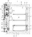
도 1은 본 발명의 일 실시예에 따른 냉장고를 도시한 사시도이다. 도 2는 도 1의 냉장고의 제빙실 도어가 개방된 상태를 도시한 도면이다. 도 3은 도 1의 냉장고의 주요 구성을 도시한 측단면도이다. 도 4는 도 1의 냉장고의 저장실 도어 및 제빙실을 도시한 분해 사시도이다.1 is a perspective view showing a refrigerator according to an embodiment of the present invention. FIG. 2 is a diagram illustrating the ice-making chamber door of the refrigerator of FIG. 1 in an open state. Figure 3 is a side cross-sectional view showing the main configuration of the refrigerator of Figure 1. FIG. 4 is an exploded perspective view showing the storage compartment door and ice-making compartment of the refrigerator of FIG. 1.
도 1 내지 도 4를 참조하면, 냉장고(1)는 저장실(21, 22)을 갖는 본체(10)와, 저장실(21, 22)의 전방에 마련되는 도어부(26, 27, 28, 29)와, 도어부(26)에 마련되는 제빙실(40)과, 제빙실(40)에 배치되는 제빙기(60) 및 아이스 버킷(80)과, 저장실(21, 22) 및 제빙실(40)에 냉기를 공급하도록 마련되는 냉기 공급 장치를 포함할 수 있다.1 to 4, the
냉기 공급 장치는 증발기(2)와, 압축기(미도시)와, 응축기(미도시)와, 팽창 장치(미도시)를 포함하고, 냉매의 증발 잠열을 이용하여 냉기를 생성할 수 있다. 증발기(2)에서 생성된 냉기는 송풍팬(3)의 동작에 의해 저장실(21) 및 제빙실(40)로 공급될 수 있다. 냉장고(1)는 증발기(2)에서 생성된 냉기를 제빙실(40)로 안내하는 냉기 덕트(미도시)를 포함할 수 있다.The cold air supply device includes an
본체(10)는 저장실(21, 22)을 형성하는 내상(11)과, 내상(12)의 외측에 결합되고 냉장고(1)의 외관을 형성하는 외상(12)과, 저장실(21, 22)을 단열하도록 내상(11)과 외상(12) 사이에 마련되는 단열재(13)를 포함할 수 있다. 내상(11)은 플라스틱 재질로 사출되어 형성될 수 있고, 외상(12)은 금속 재질로 형성될 수 있다. 단열재(13)로는 우레탄 폼 단열재(urethane foam insulation)가 사용될 수 있고, 필요에 따라 진공 단열재(vacuum insulation panel)가 함께 사용될 수 있다.The
본체(10)는 중간벽(17)을 포함할 수 있으며, 중간벽(17)에 의해 저장실(21, 22)은 상측의 저장실(21)과 하측의 저장실(22)로 구획될 수 있다. 중간벽(17)은 단열재를 포함하고 상측의 저장실(21)과 하측의 저장실(22)을 단열시킬 수 있다.The
상측의 저장실(21)은 대략 섭씨 0 ~ 5 도로 유지되어서 식품을 냉장 보관할 수 있는 냉장실로 사용될 수 있고, 하측의 저장실(22)은 대략 섭씨 영하 30 ~ 0 도로 유지되어서 식품을 냉동 보관할 수 있는 냉동실로 사용될 수 있다.The
저장실(21, 22)은 식품을 출납할 수 있도록 전면이 개방되게 마련되고, 저장실(21, 22)의 개방된 전면은 저장실(21, 22)의 전방에 회전 가능하게 마련되는 도어부(26, 27, 28, 29)에 의해 개폐될 수 있다. 저장실(21)은 도어부(26, 27)에 의해 개폐될 수 있고, 저장실(22)은 도어부(28, 29)에 의해 개폐될 수 있다.The front of the storage compartments 21 and 22 is open so that food can be put in and out, and the open front of the storage compartments 21 and 22 has a
도어부(26)는 저장실(21)을 개폐하도록 본체(10)에 회전 가능하게 결합되는 저장실 도어(30)와, 저장실 도어(30)의 전방에 회전 가능하게 마련되는 제빙실 도어(36)를 포함할 수 있다. 저장실 도어(30)는 힌지 부재(미도시)를 통해 본체(10)에 회전 가능하게 결합될 수 있다.The
제빙실 도어(36)는 힌지 부재(39)를 통해 저장실 도어(30) 또는 본체(10)에 회전 가능하게 결합될 수 있다. 저장실 도어(30)와 제빙실 도어(36)는 동일한 방향으로 회전 가능하도록 구성될 수 있다.The ice-making
제빙실 도어(36)는 저장실 도어(30)의 크기에 대응되는 크기를 가질 수 있다. 따라서, 저장실 도어(30)와 제빙실 도어(36)가 모두 닫힌 상태일 때 제빙실 도어(36)의 개구(37)를 통해 디스펜서(90)만 외부로 노출되고, 저장실 도어(30)의 다른 부분은 제빙실 도어(36)에 가려져서 노출되지 않을 수 있다.The ice-making
제빙실(40)은 저장실 도어(30)의 전면(front side)에 형성될 수 있다. 제빙실(40)은 저장실 도어(30)에 의해 저장실(21)과 구획, 분리, 독립될 수 있다.The ice-making
저장실 도어(30)는 전면판(31)과, 전면판(31)의 후면에 결합되는 후면판(32)과, 전면판(31)과 후면판(32) 사이에 마련되는 단열재(33)를 포함하고, 제빙실(40)은 전면판(31)의 일부 영역이 단열재(33) 측으로 함몰되어 형성될 수 있다. 제빙실(40)은 전면이 개방되도록 형성될 수 있다. 제빙실(40)의 개방된 전면은 제빙실 도어(36)에 의해 개폐될 수 있다.The
단열재(33)로는 본체(10)의 단열재(13)와 마찬가지로 우레탄 폼 단열재(urethane foam insulation)가 사용될 수 있고, 필요에 따라 진공 단열재(vacuum insulation panel)가 함께 사용될 수 있다. 제빙실(40)은 단열재(33)에 의해서 본체(10)의 저장실(21)과 단열될 수 있다.As the
제빙실(40)에는 얼음을 제조할 수 있는 제빙기(60)와, 제빙기(60)에서 제조된 얼음을 저장할 수 있는 아이스 버킷(80)이 배치될 수 있다. 제빙기(40)의 자세한 구조에 대해서는 후술한다.An
아이스 버킷(80)은 제빙실(40)에 분리 가능하게 배치될 수 있다. 아이스 버킷(80)의 좌우 양측에는 돌기(82a, 82b)가 형성되고, 제빙실(40)에는 이 돌기(82a, 82b)를 지지하도록 버킷 지지 리브(48)가 형성될 수 있다. 아이스 버킷(80)은 전면부(81)와, 좌측면부(82)와, 우측면부(83)와, 후면부(84)와, 바닥면부(85)로 구성된 벽부와, 상기 벽부의 내부에 형성된 얼음 저장 공간(87)을 포함할 수 있다(도 12 및 도 13 참조).The
아이스 버킷(80)에는 얼음을 교반시키고 이송시키도록 회전 가능한 이송 부재(88)와, 얼음을 분쇄하는 분쇄 칼날(89)이 마련될 수 있다. 이송 부재(88)를 구동시키는 이송 모터(48)는 제빙실(40)에 마련되며, 아이스 버킷(80)이 제빙실(40)에 장착 시에 이송 부재(88)와 이송 모터(48)가 연결되고, 아이스 버킷(80)이 제빙실(40)에서 분리 시에 이송 부재(88)와 이송 모터(48)도 연결이 끊어질 수 있다. 이를 위해 이송 부재(88)와 이송 모터(48)에는 각각 커플러(88a, 49)가 마련될 수 있다.The
아이스 버킷(80)의 하부에는 저장된 얼음을 토출시키도록 토출구(86, 도 13)가 형성되며, 아이스 버킷(80)에서 토출된 얼음은 슈트(91)를 통해 디스펜싱 공간(92)으로 제공될 수 있다.A discharge port 86 (FIG. 13) is formed at the bottom of the
이러한 구성으로, 사용자는 저장실 도어(30)를 개방할 필요 없이 제빙실 도어(36)만을 개방하여 제빙실(40)에 접근할 수 있다. 따라서, 아이스 버킷(80)에서 얼음을 꺼내거나, 아이스 버킷(80)을 제빙실(40)에서 분리하여 수리, 청소, 교체하는 등의 작업이 용이할 수 있다. 또한, 제빙실(40)에 접근 시에 저장실 도어(30)는 닫힌 상태로 유지될 수 있으므로 저장실(21)의 냉기 유출이 방지되고 에너지가 절약될 수 있다.With this configuration, the user can access the
저장실 도어(30)는 사용자에게 물과 얼음을 제공하도록 마련되는 디스펜서(90)를 포함할 수 있다. 디스펜서(90)는 물과 얼음을 제공받을 수 있도록 함몰되게 형성되는 디스펜싱 공간(92)과, 디스펜싱 공간(92)에 컵 등의 용기를 올려 놓을 수 있는 디스펜싱 트레이(93)와, 디스펜서의 작동 명령을 입력할 수 있는 디스펜싱 스위치(94)를 포함할 수 있다.The
저장실 도어(30)는 아이스 버킷(80)의 얼음을 디스펜싱 공간(92)으로 안내하도록 제빙실(40)과 디스펜싱 공간(92)을 연결하는 슈트(91)를 포함할 수 있다.The
제빙실 도어(36)는 제빙실 도어(36)가 닫힌 상태에서 저장실 도어(30)의 디스펜서(90)에 접근 가능하도록 개구(37)를 가질 수 있다. 개구(37)는 디스펜서(90)에 대응되는 위치에 형성될 수 있다.The ice-making
저장실 도어(30)의 후면에는 식품을 보관할 수 있는 도어 가드(34)가 마련될 수 있다. 저장실 도어(30)의 후면에는 저장실(21)을 밀폐하도록 본체(10)의 전면에 밀착되는 가스켓(35)이 마련되고, 제빙실 도어(36)의 후면에는 제빙실(40)을 밀폐하도록 저장실 도어(30)의 전면에 밀착되는 가스켓(38)이 마련될 수 있다.A
냉장고(1)는 물을 정수하도록 마련되는 워터 필터(98)와, 워터 필터(98)에서 정수된 물을 냉장 보관하도록 마련되는 워터 탱크(미도시)를 포함할 수 있다. 저장실 도어(30)에는 워터 필터(98)를 수용하도록 워터 필터 수용부(96)가 형성될 수 있다. 워터 필터 수용부(96)는 저장실 도어(30)는 닫히고 제빙실 도어(36)만 개방된 상태에서 접근 가능하도록 저장실 도어(30)의 전면에 형성될 수 있다. 워터 필터 수용부(96)는 전면이 개방되도록 마련되고, 워터 필터 수용부(96)의 개방된 전면에는 워터 필터 커버(97)가 탈부착 가능하게 마련될 수 있다.The
이하에서, 본 발명의 실시예에 따른 냉장고의 제빙실(40)과, 제빙기(60)의 구조 및 제빙실(40)에 제빙기(60)를 조립하는 구조에 대해 상세히 설명한다.Hereinafter, the structure of the
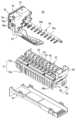
도 4는 도 1의 냉장고의 저장실 도어 및 제빙실을 도시한 분해 사시도이다. 도 5는 도 1의 냉장고의 제빙실을 도시한 저면 사시도이다. 도 6은 도 1의 냉장고의 제빙기를 도시한 사시도이다. 도 7은 도 1의 냉장고의 제빙기의 분해 사시도이다. 도 8은 도 1의 냉장고의 제빙 트레이가 가이드 리브에 지지 및 체결되는 구조를 도시한 도면이다. 도 9는 도 1의 냉장고의 모터 박스와 결합 리브가 체결 부재에 의해 체결되는 구조를 도시한 도면이다. 도 10은 도 1의 냉장고의 제빙실에 제빙기가 조립된 상태를 도시한 정면도이다.FIG. 4 is an exploded perspective view showing the storage compartment door and ice-making compartment of the refrigerator of FIG. 1. Figure 5 is a bottom perspective view showing the ice-making room of the refrigerator of Figure 1. Figure 6 is a perspective view showing the ice maker of the refrigerator of Figure 1. Figure 7 is an exploded perspective view of the ice maker of the refrigerator of Figure 1. FIG. 8 is a diagram illustrating a structure in which the ice-making tray of the refrigerator of FIG. 1 is supported and fastened to the guide rib. FIG. 9 is a diagram illustrating a structure in which the motor box of the refrigerator of FIG. 1 and the coupling rib are fastened by a fastening member. FIG. 10 is a front view showing an ice maker assembled in the ice-making compartment of the refrigerator of FIG. 1.
도 3 내지 도 4에 도시된 바와 같이, 제빙실(40)은 제빙실 벽(41)과, 제빙실 벽(41)의 의해 형성되는 제빙 공간(47)을 포함한다. 제빙실 벽(41)은 상벽(42), 하벽(43), 좌측벽(44), 우측벽(45) 및 후벽(46)을 포함할 수 있다. 제빙 공간(47)은 전면이 개방되도록 형성될 수 있다.As shown in FIGS. 3 and 4 , the
또한, 제빙실(40)은 제빙 트레이(61)를 지지하도록 형성되는 가이드 리브(50)를 포함한다. 본 실시예 및 도면에서 가이드 리브(50)는 제빙실(40)의 우측벽(45)에 마련되고 있으나, 반대로 제빙실(40)의 좌측벽(44)에 마련될 수도 있다.Additionally, the
가이드 리브(50)는 제빙 트레이(61)의 길이 방향 일단부를 지지할 수 있다. 또한, 가이드 리브(50)는 후술하는 체결 부재(S1)를 체결 시에 제빙 트레이(61)의 위치를 가이드하는 역할을 할 수 있다.The
가이드 리브(50)는 전후 방향으로 길게 형성될 수 있다. 가이드 리브(50)는 제빙실 벽과 일체로 형성될 수 있다. 다만, 이와 달리 가이드 리브(50)는 별개로 형성되어 제빙실 벽에 부착될 수도 있다.The
제빙기(60)는 물을 저수할 수 있는 제빙셀(63)을 갖는 제빙 트레이(61)와, 제빙셀(63)으로부터 얼음을 분리시키도록 회전 가능하게 마련되는 이젝터(70)와, 이젝터(70)를 회전시키도록 마련되는 이빙 모터(74, 도 14)와, 이빙 모터를 수용하도록 마련되는 모터 박스(75)와, 제빙 트레이(61)의 측면에 부착되는 측면 커버(71)와, 제빙 트레이(61)의 하부에 부착되는 하부 커버(72)와, 아이스 버킷(80)이 만빙되었는지를 감지하도록 마련되는 감지 레버(73)를 포함할 수 있다. 이러한 구성으로 제빙기는 물의 급수, 냉각, 이빙, 만빙 감지 등의 일련의 동작을 자동으로 수행할 수 있다.The
구체적으로, 제빙 트레이(61)는 복수의 제빙셀(63)과, 복수의 제빙셀(63)을 서로 구획시키는 칸막이(64)와, 칸막이(64) 사이로 물이 유동할 수 있도록 칸막이(64)에 형성되는 통과홈(65)을 갖는 셀부(62)를 포함할 수 있다. 또한, 제빙 트레이(61)는 제빙셀(63)에 공급할 물을 급수 받도록 셀부(62)의 길이 방향 일측에 마련되는 포켓부(66)를 포함할 수 있다.Specifically, the ice-making
또한, 제빙 트레이(61)는 제빙실(40)의 가이드 리브(50)에 지지되도록 셀부(62)의 길이 방향 일 단부에서 돌출되는 가이드 플랜지(67)를 포함할 수 있다. 가이드 플랜지(67)는 포켓부(66)의 아래에 위치할 수 있다.Additionally, the ice-making
가이드 플랜지(67)는 제빙 트레이(61)의 하중을 지지하도록 가이드 리브(50)의 상면(51, 도 10)에 놓이는 지지부(68)와, 제빙 트레이(61)의 인입 거리를 제한하도록 가이드 리브(50)의 전면(52)에 간섭되는 스토퍼부(69)를 포함할 수 있다. 스토퍼부(69)는 지지부(68)의 전단에서 아래로 연장되어 형성될 수 있다.The
이러한 가이드 플랜지(67)는 셀부(62)와 일체로 형성될 수 있다. 다만, 이와 달리 가이드 플랜지(67)가 별도로 형성되어 셀부(62)에 결합될 수도 있다.This
이러한 구성으로, 제빙실(40)에 제빙기(60)를 조립 시에 우선 가이드 리브(50)에 제빙 트레이(61)의 가이드 플랜지(67)를 올려 놓고 후술할 체결 부재(S1)를 체결함으로써 제빙기(60)를 고정시킬 수 있다.With this configuration, when assembling the
모터 박스(75)는 이빙 모터를 수용함으로써 이빙 모터를 보호할 수 있다. 모터 박스(75)는 제빙 트레이(61)의 길이 방향 양단부 중에 가이드 플랜지(67)가 형성되지 않은 일단부에 결합될 수 있다.The
모터 박스(75)는 내부에 모터 수용 공간(77)이 형성된 모터 박스 외벽(76)과, 제빙실 벽(41)과 결합되도록 모터 박스 외벽(76)에서 돌출되는 결합 브라켓(78)을 포함할 수 있다. 결합 브라켓(78)에는 체결 부재(S1)가 관통하는 관통공(79)이 형성될 수 있다. 체결 부재(S1)는 나사, 볼트, 핀, 리벳 등을 포함할 수 있다.The
모터 박스(75)는 제빙실 벽(41) 중에 상벽(42)에 체결될 수 있다. 이것은 제빙기(60)가 제빙실(40)의 상부에 배치되기 때문이며, 또한, 모터 박스(75)를 측벽(44, 45) 보다 상벽(42)에 결합하는 것이 조립 작업의 편의성이 있기 때문이다.The
체결 부재(S1)는 모터 박스(75)와 제빙실 상벽(42)을 체결 시에 후방으로 갈수록 위로 향하는 방향으로 경사지게 체결될 수 있다. 즉, 도 9에 도시된 바와 같이, 체결 부재(S1)가 체결되는 방향(D)과 제빙실 상벽의 내측면(42a)은 소정 각도(θ)의 경사를 가질 수 있다. 이것은 체결 부재(S1)의 체결 작업 시에 경사 방향으로 체결하는 것이 아래에서 위로 수직 방향으로 체결하는 것 보다 조립 작업의 편의성이 있기 때문이다. 이를 위해, 모터 박스(75)의 결합 브라켓(78)은 전방 상측으로 경사지게 형성될 수 있다. 이러한 결합 브라켓(78)은 모터 박스 외벽(76)과 일체로 형성될 수 있다.The fastening member S1 may be inclined in an upward direction toward the rear when fastening the
모터 박스(75)는 결합 브라켓(78)의 아래에 형성되는 가이드 홈(76a)을 가질 수 있다. 가이드 홈(76a)를 통해 체결 부재(S1)가 용이하게 결합 브라켓(78)에 접근할 수 있다. 모터 박스(75)의 모서리 일 부분이 함몰되어 경사면(76b)이 형성되고, 가이드 홈(76a)은 경사면(76b)과 결합 브라켓(78)의 사이에 형성될 수 있다.The
제빙실(40)은 상기 결합 브라켓(78)이 지지되고 상기 체결 부재(S1)가 삽입되도록 마련되는 결합 리브(55)를 포함할 수 있다. 결합 리브(55)는 제빙실 상벽(42)에 제빙 공간(47)을 향해 돌출되도록 형성될 수 있다.The ice-making
결합 브라켓(78)은 결합 리브(55)의 전면(56)에 밀착되며, 따라서, 결합 리브(55)의 전면(56)도 결합 브라켓(78)에 대응되는 각도로 경사지게 형성될 수 있다. 결합 리브(55)에는 체결 부재(S1)가 삽입되는 삽입공(57)이 형성될 수 있다. 삽입공(57)의 내주면에는 체결 부재(S1) 외주면의 나사산에 대응되도록 나사산이 형성될 수 있다.The
결합 브라켓(78) 및 결합 리브(55)는 대략 제빙셀(63)의 상측 영역인 제빙셀 영역(A, 도 6)에서 벗어난 위치에 형성되는 것이 바람직하다. 왜냐하면, 작업자가 결합 브라켓(78)과 결합 리브(55)를 체결 부재(S1)를 통해 체결하는 작업할 시에 실수로 체결 부재(S1)를 떨어뜨리는 경우에 체결 부재(S1)가 제빙셀(63) 안으로 떨어지는 것을 방지하기 위함이다.The
나아가, 제빙 트레이(61)도 제빙실 벽(41)에 체결될 수 있다. 구체적으로, 전술한 가이드 리브(50)에는 체결 부재(S2)가 삽입되는 삽입공(53)이 형성되고, 제빙 트레이(61)의 가이드 플랜지(67)에는 체결 부재(S2)가 관통하는 관통공(69a)이 형성되어, 체결 부재(S2)에 의해 제빙 트레이(61)가 제빙실 벽(41)에 체결될 수 있다.Furthermore, the
다만, 본 실시예와 달리 체결 부재(S2)는 생략 가능하다. 즉, 모터 박스(75)만 제빙실 벽(41)에 체결될 수 있다.However, unlike this embodiment, the fastening member S2 can be omitted. That is, only the
도 11은 본 발명의 다른 실시예에 따른 냉장고의 제빙실에 제빙기가 조립된 상태를 도시한 정면도이다.Figure 11 is a front view showing an ice maker assembled in the ice-making compartment of a refrigerator according to another embodiment of the present invention.
도 11을 참조하여 본 발명의 다른 실시예에 따른 냉장고의 제빙기 조립 구조를 설명한다. 전술한 실시예와 동일한 구성에 대해서는 동일한 도면 부호를 부여하고 설명을 생략할 수 있다.Referring to FIG. 11, the assembly structure of the ice maker of a refrigerator according to another embodiment of the present invention will be described. Configurations that are the same as those in the above-described embodiments may be assigned the same reference numerals and descriptions may be omitted.
전술한 실시예에서 가이드 리브(50)는 제빙실(40)의 우측벽(45)에 마련되고 있으나, 그 반대측인 제빙실(40)의 좌측벽(44)에도 추가적으로 가이드 리브(250)가 마련될 수 있다. 가이드 리브(250)는 모터 박스(75)를 지지할 수 있다. 가이드 리브(250)에는 체결 부재(S3)가 관통하는 관통공이 형성되고 모터 박스(75)에는 체결 부재(S3)가 삽입되는 삽입공이 형성될 수 있다.In the above-described embodiment, the
도 12는 도 1의 냉장고의 아이스 버킷을 도시한 사시도이다. 도 13은 도 3의 일 부분을 확대하여 도시한 도면이다. 도 14는 도 1의 냉장고의 제빙 트레이와 얼음 낙하 가이드를 도시한 평면도이다. 도 15는 도 14의 얼음 낙하 가이드가 복수로 마련된 구조를 도시한 평면도이다.FIG. 12 is a perspective view showing the ice bucket of the refrigerator of FIG. 1. FIG. 13 is an enlarged view of a portion of FIG. 3. FIG. 14 is a plan view showing the ice-making tray and ice falling guide of the refrigerator of FIG. 1. FIG. 15 is a plan view showing a structure in which a plurality of ice falling guides of FIG. 14 are provided.
도 12 내지 도 15를 참조하여, 본 발명의 실시예에 따른 얼음 낙하 가이드에 대해 설명한다.12 to 15, an ice falling guide according to an embodiment of the present invention will be described.
본 발명의 실시예에 따르면 아이스 버킷(80)의 바닥면부(85)는 높은쪽 단부(85a)와, 낮은쪽 단부(85b)를 가지며, 높은쪽 단부(85a)에서 낮은쪽 단부(85b)로 경사지게 형성될 수 있다. 이때, 높은쪽 단부(85a)는 저장실 도어(30)에 인접하고 낮은쪽 단부(85b)는 제빙실 도어(36)에 인접하게 위치될 수 있다.According to an embodiment of the present invention, the
이러한 구조에 있어서, 제빙기(60)에서 생성된 얼음이 아이스 버킷(80)의 내부로 낙하할 시에 얼음이 바닥면부(85)의 낮은쪽 단부(85) 측으로 낙하하는 경우에 충격이 크게 발생할 수 있다. 이에 따라 소음도 크게 발생하고, 얼음이 깨지는 현상이 발생할 수 있다.In this structure, when ice produced by the
본 발명의 실시예에 따르면 냉장고(1)는 얼음의 낙하 소음을 저감하고 얼음 깨짐을 축소하도록 제빙기(60)에서 낙하하는 얼음을 아이스 버킷(80)의 바닥면부(85)의 높은쪽 단부(85a) 측으로 안내하도록 마련되는 얼음 낙하 가이드(100)를 포함할 수 있다.According to an embodiment of the present invention, the
얼음 낙하 가이드(100)는 제빙 트레이(61) 보다 아래에 위치하고, 제빙실 도어(36)에 인접하게 위치할 수 있다.The
구체적으로, 얼음 낙하 가이드(100)는 아이스 버킷(80)에 일체로 형성될 수 있다. 얼음 낙하 가이드(100)는 아이스 버킷(80)의 전면부(81)에서 아이스 버킷(80)의 얼음 저장 공간(87) 측으로 돌출될 수 있다. 얼음 낙하 가이드(100)는 전방 단부(101)에서 후방 단부(102)로 갈수록 하향 경사지게 형성될 수 있다.Specifically, the
얼음 낙하 가이드(100)는 제빙 트레이(61)의 길이 방향(즉, 좌우 방향)으로 연장될 수 있으며, 얼음 낙하 가이드(100)의 길이(LIG)는 제빙 트레이(61)의 길이(LIT)의 대략 30% 이상이 되도록 형성될 수 있다.The
이러한 얼음 낙하 가이드(100)는 복수개로 마련될 수 있다. 즉, 도 15에 도시된 바와 같이, 냉장고(1)에는 복수의 얼음 낙하 가이드(110, 120)가 마련될 수 있다. 복수의 얼음 낙하 가이드(110, 120)는 제빙 트레이(61)의 길이 방향으로 배열될 수 있으며, 복수의 얼음 낙하 가이드(110, 120)의 사이에는 소정의 간격(G)이 형성될 수 있다. 얼음 낙하 가이드(110)의 길이(LIG1)와 얼음 낙하 가이드(120)의 길이(LIG2)의 합은 제빙 트레이(61)의 길이(LIT)의 대략 30% 이상이 될 수 있다.A plurality of such ice falling guides 100 may be provided. That is, as shown in FIG. 15, the
도 16은 본 발명의 다른 실시예에 따른 얼음 낙하 가이드를 도시한 단면도이다.Figure 16 is a cross-sectional view showing an ice falling guide according to another embodiment of the present invention.
도 16을 참조하여, 본 발명의 다른 실시예에 따른 얼음 낙하 가이드를 설명한다. 전술한 실시예와 동일한 구성에 대해서는 동일한 도면 부호를 부여하고 설명을 생략할 수 있다.With reference to FIG. 16, an ice falling guide according to another embodiment of the present invention will be described. Configurations that are the same as those in the above-described embodiments may be assigned the same reference numerals and descriptions may be omitted.
얼음 낙하 가이드(130)는 제빙기 커버(131)에 일체로 형성될 수 있다. 제빙기 커버(131)는 아이스 버킷(80)과는 별개의 부품으로 마련되고, 제빙기(60)를 커버하도록 제빙기(60)의 전방에 마련될 수 있다.The
얼음 낙하 가이드(130)는 제빙기 커버(131)에서 아이스 버킷(80)의 얼음 저장 공간(87)을 향해 돌출될 수 있다. 얼음 낙하 가이드(130)는 전방 단부에서 후방 단부로 갈수록 하향 경사지게 형성될 수 있다.The
도 17은 본 발명의 또 다른 실시예에 따른 얼음 낙하 가이드를 도시한 단면도이다.Figure 17 is a cross-sectional view showing an ice falling guide according to another embodiment of the present invention.
도 17을 참조하여, 본 발명의 또 다른 실시예에 따른 얼음 낙하 가이드를 설명한다. 전술한 실시예와 동일한 구성에 대해서는 동일한 도면 부호를 부여하고 설명을 생략할 수 있다.With reference to FIG. 17, an ice falling guide according to another embodiment of the present invention will be described. Configurations that are the same as those in the above-described embodiments may be assigned the same reference numerals and descriptions may be omitted.
얼음 낙하 가이드(140)는 제빙실 도어(36)에 일체로 형성될 수 있다. 얼음 낙하 가이드(140)는 제빙실 도어(36)에서 아이스 버킷(80)의 얼음 저장 공간(87)을 향해 돌출될 수 있다. 얼음 낙하 가이드(140)는 전방 단부에서 후방 단부로 갈수록 하향 경사지게 형성될 수 있다.The
특정 실시예에 의하여 상기와 같은 본 발명의 기술적 사상을 설명하였으나 본 발명의 권리범위는 이러한 실시예에 한정되는 것이 아니다. 특허청구범위에 명시된 본 발명의 기술적 사상으로서의 요지를 일탈하지 아니하는 범위 안에서 당분야에서 통상의 지식을 가진 자에 의하여 수정 또는 변형 가능한 다양한 실시예들도 본 발명의 권리범위에 속한다 할 것이다.Although the technical idea of the present invention has been described above through specific examples, the scope of the present invention is not limited to these examples. Various embodiments that can be modified or modified by a person skilled in the art without departing from the gist of the technical idea of the present invention as specified in the patent claims will also fall within the scope of the present invention.
1 : 냉장고10 : 본체
21 : 냉장실22 : 냉동실
26, 27, 28, 29 : 도어부30 : 저장실 도어
36 : 제빙실 도어37 : 개구
40 : 제빙실41 : 제빙실 벽
42 : 제빙실 상벽43 : 제빙실 하벽
44 : 제빙실 좌측벽45 : 제빙실 우측벽
46 : 제빙실 후벽47 : 제빙 공간
50 : 가이드 리브51 : 가이드 리브 상면
52 : 가이드 리브 전면53 : 삽입공
55 : 결합 리브56 : 결합 리브 전면
57 : 삽입공60 : 제빙기
61 : 제빙 트레이62 : 셀부
63 : 제빙셀66 : 포켓부
67 : 가이드 플랜지68 : 지지부
69 : 스토퍼부69a : 관통공
75 : 모터 박스76 : 모터 박스 외벽
76a : 가이드 홈76b : 경사면
78 : 결합 브라켓79 : 관통공
80 : 아이스 버킷아이스 버킷81 : 전면부
82 : 좌측면부83 : 우측면부
84 : 후면부85 : 바닥면부
85a : 높은쪽 단부85b : 낮은쪽 단부
86 : 얼음 토출구87 : 얼음 저장 공간
88 : 이송 부재88a : 커플러
89 : 분쇄 칼날48 : 이송 모터
49 : 커플러82a, 82b : 돌기
90 : 디스펜서91 : 슈트
92 : 디스펜싱 공간93 : 디스펜싱 트레이
94 : 디스펜싱 스위치96 : 워터 필터 수용부
97 : 워터 필터 커버98 : 워터 필터
100 : 얼음 낙하 가이드101, 102 : 전방 단부, 후방 단부1: refrigerator 10: main body
21: Refrigerator 22: Freezer
26, 27, 28, 29: Door part 30: Storage room door
36: Ice room door 37: Opening
40: Ice-making room 41: Ice-making room wall
42: upper wall of ice-making room 43: lower wall of ice-making room
44: Left wall of ice-making room 45: Right wall of ice-making room
46: Rear wall of ice-making room 47: Ice-making space
50: Guide rib 51: Guide rib upper surface
52: Front of guide rib 53: Insertion hole
55: Coupling rib 56: Coupling rib front
57: Insertion hole 60: Ice maker
61: Ice-making tray 62: Selbu
63: Ice-making cell 66: Pocket part
67: guide flange 68: support
69:
75: Motor box 76: Motor box outer wall
76a:
78: Combination bracket 79: Through hole
80: Ice bucketIce bucket 81: Front part
82: left side 83: right side
84: rear part 85: bottom part
85a:
86: Ice outlet 87: Ice storage space
88:
89: Grinding blade 48: Transport motor
49:
90: Dispenser 91: Chute
92: dispensing space 93: dispensing tray
94: Dispensing switch 96: Water filter receiving portion
97: Water filter cover 98: Water filter
100:
Claims (25)
Translated fromKorean상기 본체에 마련된 저장실;
상기 저장실을 개폐하도록 상기 본체에 회전 가능하게 결합된 저장실 도어;
상기 저장실 도어에 마련된 제빙실로서, 상기 제빙실은 삽입공이 형성된 상벽, 하벽, 좌측벽, 우측벽 및 후벽을 포함하는 제빙실 벽과, 상기 제빙실 벽에 의해 형성되고 전면이 개방된 제빙 공간을 포함하고, 상기 제빙실 벽은 상기 제빙 공간을 향해 돌출되는 가이드 리브를 포함하는 제빙실;
상기 제빙실에 상측에 배치되는 제빙기로서, 상기 제빙기는 물을 저수하는 제빙셀을 갖고 상기 가이드 리브에 지지되는 제빙 트레이와, 상기 제빙셀에서 얼음을 분리시키도록 회전 가능한 이젝터와, 상기 이젝터를 회전시키는 이빙 모터를 수용하도록 상기 제빙 트레이의 길이 방향 일 측에 결합된 모터 박스를 포함하는 제빙기; 및
상기 제빙기를 고정시키도록 상기 모터 박스를 상기 제빙실 벽에 체결시키는 체결 부재; 를 포함하고,
상기 모터 박스는,
모터 박스 외벽;
상기 상벽에 결합되도록 모터 박스 외벽에서 돌출되고, 전방 상측으로 경사지게 형성되는 결합 브라켓; 및
상기 결합 브라켓의 아래에 형성되는 가이드 홈을 포함하고,
상기 체결 부재는 상기 모터 박스를 상기 상벽에 고정시키도록, 상기 가이드 홈을 따라 상기 결합 브라켓을 통하여 상기 삽입공을 향하여 연장되고, 후방으로 갈수록 위로 향하는 방향으로 경사지게 상기 모터 박스와 상기 상벽에 체결되는 냉장고.main body;
a storage compartment provided in the main body;
a storage compartment door rotatably coupled to the main body to open and close the storage compartment;
An ice-making room provided in the storage compartment door, wherein the ice-making room includes an ice-making room wall including an upper wall, a lower wall, a left wall, a right wall, and a rear wall in which an insertion hole is formed, and an ice-making space formed by the ice-making room wall and having an open front. and an ice-making chamber wall including a guide rib protruding toward the ice-making space;
An ice maker disposed above the ice-making chamber, the ice-making machine having an ice-making cell that stores water, an ice-making tray supported on the guide rib, an ejector rotatable to separate ice from the ice-making cell, and rotating the ejector. an ice maker including a motor box coupled to one longitudinal side of the ice tray to accommodate a moving motor; and
a fastening member for fastening the motor box to the wall of the ice-making chamber to fix the ice-making machine; Including,
The motor box is,
Motor box outer wall;
A coupling bracket protrudes from the outer wall of the motor box to be coupled to the upper wall and is inclined toward the front and upward; and
It includes a guide groove formed below the coupling bracket,
The fastening member extends toward the insertion hole through the coupling bracket along the guide groove to secure the motor box to the upper wall, and is inclined in an upward direction toward the rear and is fastened to the motor box and the upper wall. refrigerator.
상기 가이드 리브는 상기 좌측벽 또는 상기 우측벽에 형성된 냉장고.According to paragraph 1,
The guide rib is formed on the left wall or the right wall.
상기 가이드 리브는 전후 방향으로 길게 형성된 냉장고.According to paragraph 1,
A refrigerator in which the guide rib is formed to be long in the front-back direction.
상기 가이드 리브는 상기 제빙실 벽과 일체로 형성된 냉장고.According to paragraph 1,
A refrigerator in which the guide rib is formed integrally with a wall of the ice-making chamber.
상기 제빙 트레이는 내부에 상기 제빙셀이 형성되는 셀부와, 상기 가이드 리브에 지지되도록 상기 셀부에서 돌출되는 가이드 플랜지를 포함하는 냉장고.According to paragraph 1,
The ice-making tray is a refrigerator including a cell portion in which the ice-making cell is formed, and a guide flange protruding from the cell portion to be supported by the guide rib.
상기 셀부와 상기 가이드 플랜지는 일체로 형성된 냉장고.According to clause 5,
A refrigerator in which the cell portion and the guide flange are integrally formed.
상기 제빙 트레이는 상기 제빙셀에 공급할 물을 급수 받도록 상기 셀부에서 돌출되는 포켓부를 포함하고,
상기 가이드 플랜지는 상기 포켓부의 아래에 위치하는 냉장고.According to clause 5,
The ice-making tray includes a pocket portion protruding from the cell portion to receive water to be supplied to the ice-making cell,
The guide flange is located below the pocket portion of the refrigerator.
상기 가이드 플랜지는 상기 가이드 리브의 상면에 놓이도록 형성되는 지지부와, 상기 가이드 리브의 전면에 걸리도록 형성되는 스토퍼부를 포함하는 냉장고.According to clause 5,
The guide flange includes a support portion formed to be placed on the upper surface of the guide rib, and a stopper portion formed to be caught on the front surface of the guide rib.
상기 제빙실의 상벽은 상기 제빙 공간을 향해 돌출되고 상기 체결 부재가 삽입되는 삽입공이 형성되는 결합 리브를 포함하는 냉장고.According to paragraph 1,
The upper wall of the ice-making chamber includes a coupling rib that protrudes toward the ice-making space and forms an insertion hole into which the fastening member is inserted.
상기 결합 브라켓은 상기 제빙셀의 상측 영역인 제빙셀 영역에서 벗어난 위치에 형성된 냉장고.In paragraph 1,
The coupling bracket is formed in a position away from the ice-making cell area, which is an upper area of the ice-making cell.
상기 제빙 트레이는 내부에 상기 제빙셀이 형성되는 셀부와, 상기 가이드 리브에 지지되도록 상기 셀부에서 돌출되는 가이드 플랜지를 포함하고,
상기 제빙기를 고정시키도록 상기 제빙 트레이를 상기 제빙실 벽에 체결시키는 또 다른 체결 부재를 더 포함하는 냉장고.According to paragraph 1,
The ice-making tray includes a cell portion in which the ice-making cell is formed, and a guide flange protruding from the cell portion to be supported by the guide rib,
The refrigerator further includes another fastening member that fastens the ice making tray to the wall of the ice making chamber to fix the ice maker.
상기 가이드 리브에 상기 또 다른 체결 부재가 삽입되는 삽입공이 형성된 냉장고.According to clause 15,
A refrigerator having an insertion hole through which the another fastening member is inserted into the guide rib.
상기 가이드 플랜지에 상기 또 다른 체결 부재가 관통하는 관통공이 형성된 냉장고.According to clause 15,
A refrigerator in which a through hole through which the another fastening member penetrates is formed in the guide flange.
상기 제빙실의 좌측벽 및 우측벽 중에 상기 가이드 리브가 형성되지 않은 나머지 하나에 형성되는 또 다른 가이드 리브를 더 포함하는 냉장고.According to paragraph 1,
The refrigerator further includes another guide rib formed on the remaining one of the left and right walls of the ice-making chamber where the guide rib is not formed.
Priority Applications (4)
| Application Number | Priority Date | Filing Date | Title |
|---|---|---|---|
| PCT/KR2018/011600WO2019066595A1 (en) | 2017-09-29 | 2018-09-28 | Refrigerator |
| CN201880062499.5ACN111164361B (en) | 2017-09-29 | 2018-09-28 | refrigerator |
| EP18860380.7AEP3667205B1 (en) | 2017-09-29 | 2018-09-28 | Refrigerator |
| US16/652,239US11573043B2 (en) | 2017-09-29 | 2018-09-28 | Refrigerator |
Applications Claiming Priority (2)
| Application Number | Priority Date | Filing Date | Title |
|---|---|---|---|
| KR20170127967 | 2017-09-29 | ||
| KR1020170127967 | 2017-09-29 |
Publications (2)
| Publication Number | Publication Date |
|---|---|
| KR20190038275A KR20190038275A (en) | 2019-04-08 |
| KR102628625B1true KR102628625B1 (en) | 2024-01-26 |
Family
ID=66164886
Family Applications (1)
| Application Number | Title | Priority Date | Filing Date |
|---|---|---|---|
| KR1020180066893AActiveKR102628625B1 (en) | 2017-09-29 | 2018-06-11 | Refrigerator |
Country Status (3)
| Country | Link |
|---|---|
| US (1) | US11573043B2 (en) |
| EP (1) | EP3667205B1 (en) |
| KR (1) | KR102628625B1 (en) |
Families Citing this family (2)
| Publication number | Priority date | Publication date | Assignee | Title |
|---|---|---|---|---|
| KR20210061102A (en) | 2019-11-19 | 2021-05-27 | 삼성전자주식회사 | Refrigerator |
| CN114963640B (en)* | 2021-02-18 | 2024-05-24 | 内蒙古伊利实业集团股份有限公司 | Door assembly and refrigerator |
Citations (1)
| Publication number | Priority date | Publication date | Assignee | Title |
|---|---|---|---|---|
| KR101731024B1 (en)* | 2015-09-11 | 2017-04-27 | 주식회사 바디프랜드 | Ice Dispenser of Water Purifier And Method of Controoling the Same |
Family Cites Families (16)
| Publication number | Priority date | Publication date | Assignee | Title |
|---|---|---|---|---|
| KR100827776B1 (en) | 2002-04-13 | 2008-05-07 | 엘지전자 주식회사 | Apparatus for installation of ice maker unit |
| KR100565497B1 (en)* | 2003-10-07 | 2006-03-30 | 엘지전자 주식회사 | Ice detection device and detection method |
| KR20050110214A (en) | 2004-05-18 | 2005-11-23 | 주식회사 대창 | Cohesion structure of ice maker |
| DE102006063088B3 (en) | 2005-09-23 | 2023-07-06 | Lg Electronics Inc. | refrigerator door |
| KR100743748B1 (en)* | 2005-11-16 | 2007-07-27 | 엘지전자 주식회사 | Ice Maker Installation Structure of Refrigerator Door |
| KR100790545B1 (en)* | 2006-03-23 | 2008-01-02 | 엘지전자 주식회사 | Refrigerator ice maker |
| US8443620B2 (en)* | 2006-08-15 | 2013-05-21 | Lg Electronics Inc. | Ice tray assembly and refrigerator having same |
| KR100783236B1 (en) | 2006-09-06 | 2007-12-06 | 엘지전자 주식회사 | Refrigerator ice tray assembly and refrigerator having same |
| KR20080068440A (en)* | 2007-01-19 | 2008-07-23 | 삼성전자주식회사 | Ice maker and refrigerator with same |
| KR101631089B1 (en)* | 2008-08-13 | 2016-06-17 | 삼성전자주식회사 | Ice maker and refrigerator having the same |
| KR101570349B1 (en) | 2008-11-21 | 2015-11-19 | 엘지전자 주식회사 | Refrigerator |
| KR101669420B1 (en)* | 2010-01-04 | 2016-10-27 | 삼성전자주식회사 | Refrigerator |
| KR20120040891A (en) | 2010-10-20 | 2012-04-30 | 삼성전자주식회사 | Refrigerator |
| KR101502112B1 (en)* | 2012-04-10 | 2015-03-13 | 삼성전자 주식회사 | Refrigerator And Manufacturing Method Thereof |
| KR20140059938A (en)* | 2012-11-09 | 2014-05-19 | 삼성전자주식회사 | Refrigerator |
| CN105627679A (en) | 2014-10-29 | 2016-06-01 | 海信容声(广东)冰箱有限公司 | Refrigerator |
- 2018
- 2018-06-11KRKR1020180066893Apatent/KR102628625B1/enactiveActive
- 2018-09-28USUS16/652,239patent/US11573043B2/enactiveActive
- 2018-09-28EPEP18860380.7Apatent/EP3667205B1/enactiveActive
Patent Citations (1)
| Publication number | Priority date | Publication date | Assignee | Title |
|---|---|---|---|---|
| KR101731024B1 (en)* | 2015-09-11 | 2017-04-27 | 주식회사 바디프랜드 | Ice Dispenser of Water Purifier And Method of Controoling the Same |
Also Published As
| Publication number | Publication date |
|---|---|
| EP3667205B1 (en) | 2021-07-07 |
| US11573043B2 (en) | 2023-02-07 |
| EP3667205A1 (en) | 2020-06-17 |
| KR20190038275A (en) | 2019-04-08 |
| US20200240696A1 (en) | 2020-07-30 |
| EP3667205A4 (en) | 2020-09-30 |
Similar Documents
| Publication | Publication Date | Title |
|---|---|---|
| US11079164B2 (en) | Refrigerator | |
| US11384973B2 (en) | Refrigerator | |
| EP3745058B1 (en) | Refrigerator | |
| US11313615B2 (en) | Refrigerator | |
| EP2650625B1 (en) | Refrigerator | |
| US9212841B2 (en) | Refrigerator | |
| US20110146331A1 (en) | Refrigerator | |
| US20210148627A1 (en) | Refrigerator | |
| CN108266946A (en) | Refrigerator | |
| KR102189239B1 (en) | Refrigerator | |
| US11859893B2 (en) | Refrigerator | |
| US20120255322A1 (en) | Refrigerator with auxiliary basket | |
| KR102628625B1 (en) | Refrigerator | |
| US12203695B2 (en) | Refrigerator | |
| CN111164361B (en) | refrigerator | |
| KR102491598B1 (en) | Refrigerator | |
| US11512886B2 (en) | Refrigerator | |
| JPH11108515A (en) | Refrigerator with automatic ice machine |
Legal Events
| Date | Code | Title | Description |
|---|---|---|---|
| PA0109 | Patent application | St.27 status event code:A-0-1-A10-A12-nap-PA0109 | |
| PG1501 | Laying open of application | St.27 status event code:A-1-1-Q10-Q12-nap-PG1501 | |
| PA0201 | Request for examination | St.27 status event code:A-1-2-D10-D11-exm-PA0201 | |
| D13-X000 | Search requested | St.27 status event code:A-1-2-D10-D13-srh-X000 | |
| D14-X000 | Search report completed | St.27 status event code:A-1-2-D10-D14-srh-X000 | |
| E902 | Notification of reason for refusal | ||
| PE0902 | Notice of grounds for rejection | St.27 status event code:A-1-2-D10-D21-exm-PE0902 | |
| E13-X000 | Pre-grant limitation requested | St.27 status event code:A-2-3-E10-E13-lim-X000 | |
| P11-X000 | Amendment of application requested | St.27 status event code:A-2-2-P10-P11-nap-X000 | |
| P13-X000 | Application amended | St.27 status event code:A-2-2-P10-P13-nap-X000 | |
| E90F | Notification of reason for final refusal | ||
| PE0902 | Notice of grounds for rejection | St.27 status event code:A-1-2-D10-D21-exm-PE0902 | |
| P11-X000 | Amendment of application requested | St.27 status event code:A-2-2-P10-P11-nap-X000 | |
| P13-X000 | Application amended | St.27 status event code:A-2-2-P10-P13-nap-X000 | |
| E701 | Decision to grant or registration of patent right | ||
| PE0701 | Decision of registration | St.27 status event code:A-1-2-D10-D22-exm-PE0701 | |
| PR0701 | Registration of establishment | St.27 status event code:A-2-4-F10-F11-exm-PR0701 | |
| PR1002 | Payment of registration fee | St.27 status event code:A-2-2-U10-U11-oth-PR1002 Fee payment year number:1 | |
| PG1601 | Publication of registration | St.27 status event code:A-4-4-Q10-Q13-nap-PG1601 |