KR102628024B1 - Foldable display device - Google Patents
Foldable display deviceDownload PDFInfo
- Publication number
- KR102628024B1 KR102628024B1KR1020160129963AKR20160129963AKR102628024B1KR 102628024 B1KR102628024 B1KR 102628024B1KR 1020160129963 AKR1020160129963 AKR 1020160129963AKR 20160129963 AKR20160129963 AKR 20160129963AKR 102628024 B1KR102628024 B1KR 102628024B1
- Authority
- KR
- South Korea
- Prior art keywords
- support
- support surface
- display panel
- link members
- protrusions
- Prior art date
- Legal status (The legal status is an assumption and is not a legal conclusion. Google has not performed a legal analysis and makes no representation as to the accuracy of the status listed.)
- Active
Links
Images


Classifications
- G—PHYSICS
- G09—EDUCATION; CRYPTOGRAPHY; DISPLAY; ADVERTISING; SEALS
- G09F—DISPLAYING; ADVERTISING; SIGNS; LABELS OR NAME-PLATES; SEALS
- G09F9/00—Indicating arrangements for variable information in which the information is built-up on a support by selection or combination of individual elements
- G09F9/30—Indicating arrangements for variable information in which the information is built-up on a support by selection or combination of individual elements in which the desired character or characters are formed by combining individual elements
- G09F9/301—Indicating arrangements for variable information in which the information is built-up on a support by selection or combination of individual elements in which the desired character or characters are formed by combining individual elements flexible foldable or roll-able electronic displays, e.g. thin LCD, OLED
- G—PHYSICS
- G02—OPTICS
- G02F—OPTICAL DEVICES OR ARRANGEMENTS FOR THE CONTROL OF LIGHT BY MODIFICATION OF THE OPTICAL PROPERTIES OF THE MEDIA OF THE ELEMENTS INVOLVED THEREIN; NON-LINEAR OPTICS; FREQUENCY-CHANGING OF LIGHT; OPTICAL LOGIC ELEMENTS; OPTICAL ANALOGUE/DIGITAL CONVERTERS
- G02F1/00—Devices or arrangements for the control of the intensity, colour, phase, polarisation or direction of light arriving from an independent light source, e.g. switching, gating or modulating; Non-linear optics
- G02F1/01—Devices or arrangements for the control of the intensity, colour, phase, polarisation or direction of light arriving from an independent light source, e.g. switching, gating or modulating; Non-linear optics for the control of the intensity, phase, polarisation or colour
- G02F1/13—Devices or arrangements for the control of the intensity, colour, phase, polarisation or direction of light arriving from an independent light source, e.g. switching, gating or modulating; Non-linear optics for the control of the intensity, phase, polarisation or colour based on liquid crystals, e.g. single liquid crystal display cells
- G02F1/133—Constructional arrangements; Operation of liquid crystal cells; Circuit arrangements
- G02F1/1333—Constructional arrangements; Manufacturing methods
- G02F1/133305—Flexible substrates, e.g. plastics, organic film
- G—PHYSICS
- G06—COMPUTING OR CALCULATING; COUNTING
- G06F—ELECTRIC DIGITAL DATA PROCESSING
- G06F1/00—Details not covered by groups G06F3/00 - G06F13/00 and G06F21/00
- G06F1/16—Constructional details or arrangements
- G06F1/1613—Constructional details or arrangements for portable computers
- G06F1/1633—Constructional details or arrangements of portable computers not specific to the type of enclosures covered by groups G06F1/1615 - G06F1/1626
- G06F1/1637—Details related to the display arrangement, including those related to the mounting of the display in the housing
- G06F1/1641—Details related to the display arrangement, including those related to the mounting of the display in the housing the display being formed by a plurality of foldable display components
- G—PHYSICS
- G06—COMPUTING OR CALCULATING; COUNTING
- G06F—ELECTRIC DIGITAL DATA PROCESSING
- G06F1/00—Details not covered by groups G06F3/00 - G06F13/00 and G06F21/00
- G06F1/16—Constructional details or arrangements
- G06F1/1613—Constructional details or arrangements for portable computers
- G06F1/1633—Constructional details or arrangements of portable computers not specific to the type of enclosures covered by groups G06F1/1615 - G06F1/1626
- G06F1/1637—Details related to the display arrangement, including those related to the mounting of the display in the housing
- G06F1/1652—Details related to the display arrangement, including those related to the mounting of the display in the housing the display being flexible, e.g. mimicking a sheet of paper, or rollable
- G—PHYSICS
- G06—COMPUTING OR CALCULATING; COUNTING
- G06F—ELECTRIC DIGITAL DATA PROCESSING
- G06F1/00—Details not covered by groups G06F3/00 - G06F13/00 and G06F21/00
- G06F1/16—Constructional details or arrangements
- G06F1/1613—Constructional details or arrangements for portable computers
- G06F1/1633—Constructional details or arrangements of portable computers not specific to the type of enclosures covered by groups G06F1/1615 - G06F1/1626
- G06F1/1675—Miscellaneous details related to the relative movement between the different enclosures or enclosure parts
- G06F1/1681—Details related solely to hinges
- H—ELECTRICITY
- H10—SEMICONDUCTOR DEVICES; ELECTRIC SOLID-STATE DEVICES NOT OTHERWISE PROVIDED FOR
- H10K—ORGANIC ELECTRIC SOLID-STATE DEVICES
- H10K77/00—Constructional details of devices covered by this subclass and not covered by groups H10K10/80, H10K30/80, H10K50/80 or H10K59/80
- H10K77/10—Substrates, e.g. flexible substrates
- H10K77/111—Flexible substrates
- G—PHYSICS
- G06—COMPUTING OR CALCULATING; COUNTING
- G06F—ELECTRIC DIGITAL DATA PROCESSING
- G06F2203/00—Indexing scheme relating to G06F3/00 - G06F3/048
- G06F2203/041—Indexing scheme relating to G06F3/041 - G06F3/045
- G06F2203/04102—Flexible digitiser, i.e. constructional details for allowing the whole digitising part of a device to be flexed or rolled like a sheet of paper
- Y—GENERAL TAGGING OF NEW TECHNOLOGICAL DEVELOPMENTS; GENERAL TAGGING OF CROSS-SECTIONAL TECHNOLOGIES SPANNING OVER SEVERAL SECTIONS OF THE IPC; TECHNICAL SUBJECTS COVERED BY FORMER USPC CROSS-REFERENCE ART COLLECTIONS [XRACs] AND DIGESTS
- Y02—TECHNOLOGIES OR APPLICATIONS FOR MITIGATION OR ADAPTATION AGAINST CLIMATE CHANGE
- Y02E—REDUCTION OF GREENHOUSE GAS [GHG] EMISSIONS, RELATED TO ENERGY GENERATION, TRANSMISSION OR DISTRIBUTION
- Y02E10/00—Energy generation through renewable energy sources
- Y02E10/50—Photovoltaic [PV] energy
- Y02E10/549—Organic PV cells
Landscapes
- Engineering & Computer Science (AREA)
- Physics & Mathematics (AREA)
- Theoretical Computer Science (AREA)
- General Physics & Mathematics (AREA)
- Computer Hardware Design (AREA)
- General Engineering & Computer Science (AREA)
- Human Computer Interaction (AREA)
- Nonlinear Science (AREA)
- Devices For Indicating Variable Information By Combining Individual Elements (AREA)
- Mathematical Physics (AREA)
- Chemical & Material Sciences (AREA)
- Crystallography & Structural Chemistry (AREA)
- Optics & Photonics (AREA)
- Electroluminescent Light Sources (AREA)
- Liquid Crystal (AREA)
Abstract
Translated fromKoreanDescription
Translated fromKorean본 개시는 폴더블 표시 장치에 관한 것으로서, 보다 상세하게는 표시 패널에 결합된 패널 지지부의 구조에 관한 것이다.The present disclosure relates to a foldable display device, and more specifically, to the structure of a panel support unit coupled to a display panel.
가요성(flexible) 표시 패널은 가요성 기판과, 가요성 기판 상에 배치된 표시부를 포함하며, 쉽게 휘어지는 성질을 가진다. 최근, 가요성 표시 패널을 이용하여 화면을 구부리거나 반으로 접을 수 있는 폴더블(foldable, 접이식) 표시 장치가 개발되고 있다.A flexible display panel includes a flexible substrate and a display portion disposed on the flexible substrate, and has the property of being easily bent. Recently, foldable display devices that can bend or fold the screen in half using a flexible display panel have been developed.
폴더블 표시 장치는 가요성 표시 패널과, 가요성 표시 패널에 결합된 패널 지지부를 포함한다. 패널 지지부는 가요성 표시 패널과 함께 폴딩 동작이 이루어지는 구조를 가진다. 패널 지지부는 가요성 표시 패널을 안정적으로 지지해야 하고, 폴딩 상태에서 가요성 표시 패널을 변형시키지 않아야 한다.A foldable display device includes a flexible display panel and a panel supporter coupled to the flexible display panel. The panel support unit has a structure in which a folding operation is performed together with the flexible display panel. The panel supporter must stably support the flexible display panel and not deform the flexible display panel in a folded state.
본 개시는 폴딩 상태에서 가요성 표시 패널이 받는 스트레스를 최소화할 수 있는 폴더블 표시 장치를 제공하고자 한다.The present disclosure seeks to provide a foldable display device that can minimize stress on a flexible display panel in a folded state.
일 실시예에 따른 폴더블 표시 장치는 표시 패널과 패널 지지부를 포함한다. 표시 패널은 표시부가 위치하는 제1면과, 제1면과 반대 측에 위치하는 제2면을 가지며, 벤딩 가능 영역을 포함한다. 패널 지지부는 제2면과 마주하며 표시 패널에 결합된다. 패널 지지부는 벤딩 가능 영역에 대응하여 제1 방향을 따라 나란하게 배열된 복수의 링크 부재를 포함한다. 복수의 링크 부재 각각은 표시 패널과 마주하는 제1 지지면을 가지며, 두 개의 회전축을 중심으로 회전 가능하게 결합된다. 복수의 링크 부재 각각의 두 개의 회전축은 제2면으로부터 제1면을 향하는 방향을 따라 제1 지지면과 이격되어 있다.A foldable display device according to an embodiment includes a display panel and a panel supporter. The display panel has a first surface on which the display unit is located, a second surface on an opposite side from the first surface, and includes a bendable area. The panel support portion faces the second side and is coupled to the display panel. The panel support unit includes a plurality of link members arranged in parallel along a first direction corresponding to the bendable area. Each of the plurality of link members has a first support surface facing the display panel and is rotatably coupled about two rotation axes. The two rotation axes of each of the plurality of link members are spaced apart from the first support surface along a direction from the second surface to the first surface.
복수의 링크 부재가 포함하는 복수의 제1 지지면은 펼침 상태에서 서로 이격될 수 있고, 복수의 링크 부재 각각의 두 개의 회전축 사이의 거리는 제1 지지면의 폭보다 클 수 있다. 복수의 링크 부재 각각은, 제1 지지면의 양측 단부 아래에 위치하며 제1 지지면과 연결되는 두 개의 하부 경사면과, 제1 방향과 교차하는 제2 방향에 따른 제1 지지면의 양측 단부에 위치하는 두 개의 제1 돌출부를 더 포함할 수 있다.The plurality of first support surfaces included in the plurality of link members may be spaced apart from each other in the unfolded state, and the distance between the two rotation axes of each of the plurality of link members may be greater than the width of the first support surface. Each of the plurality of link members has two lower inclined surfaces located below both ends of the first support surface and connected to the first support surface, and at both ends of the first support surface along a second direction intersecting the first direction. It may further include two first protrusions located thereon.
두 개의 제1 돌출부 각각은 단면상에서 두 개의 하부 경사면과 동일 평면 상에 위치하는 두 개의 상부 경사면을 포함할 수 있고, 두 개의 회전축은 두 개의 상부 경사면의 상측 단부에 위치할 수 있다. 두 개의 제1 돌출부 각각은 두 개의 상부 경사면 상에 위치하는 두 개의 수직면을 더 포함할 수 있고, 펼침 상태에서, 두 개의 수직면은 제1 방향을 따라 이웃한 제1 돌출부가 포함하는 수직면과 접촉할 수 있다.Each of the two first protrusions may include two lower inclined surfaces and two upper inclined surfaces located on the same plane in cross-section, and the two rotation axes may be located at upper ends of the two upper inclined surfaces. Each of the two first protrusions may further include two vertical surfaces located on the two upper inclined surfaces, and in the unfolded state, the two vertical surfaces may be in contact with a vertical surface including a neighboring first protrusion along the first direction. You can.
폴딩 상태에서, 복수의 제1 지지면은 서로 이어질 수 있고, 두 개의 하부 경사면은 이웃한 링크 부재의 하부 경사면에 밀착될 수 있으며, 벤딩 가능 영역은 원호 모양으로 벤딩될 수 있다.In the folded state, the plurality of first support surfaces may be connected to each other, the two lower inclined surfaces may be in close contact with the lower inclined surfaces of adjacent link members, and the bendable area may be bent into an arc shape.
표시 패널은 벤딩 가능 영역의 양측에 위치하는 두 개의 평탄 영역을 더 포함할 수 있고, 패널 지지부는 두 개의 평탄 영역에 대응하는 두 개의 지지판을 더 포함할 수 있다. 두 개의 지지판 각각은 표시 패널과 마주하는 제2 지지면과, 제2 방향에 따른 제2 지지면의 양측 단부에 위치하는 두 개의 제2 돌출부를 포함할 수 있다. 두 개의 제2 돌출부와 복수의 링크 부재가 포함하는 복수의 제1 돌출부는 회전축을 가지는 회전 결합부에 의해 상호 결합될 수 있다.The display panel may further include two flat areas located on both sides of the bendable area, and the panel supporter may further include two support plates corresponding to the two flat areas. Each of the two support plates may include a second support surface facing the display panel and two second protrusions located at both ends of the second support surface in the second direction. The two second protrusions and the plurality of first protrusions including the plurality of link members may be coupled to each other by a rotational coupler having a rotation axis.
펼침 상태에서, 두 개의 제2 지지면은 복수의 제1 지지면과 나란할 수 있고, 폴딩 상태에서, 복수의 제1 지지면 중 최외곽 제1 지지면의 가장자리는 제2 지지면으로부터 벤딩 가능 영역의 곡률 중심을 향해 이격될 수 있다. 폴딩 상태에서, 복수의 제1 지지면은 두 개의 제2 지지면을 연결하는 가상 원호의 내측에 위치할 수 있다.In the unfolded state, the two second support surfaces can be parallel to the plurality of first support surfaces, and in the folded state, the edge of the outermost first support surface among the plurality of first support surfaces can be bent from the second support surface. They may be spaced toward the center of curvature of the region. In the folded state, the plurality of first support surfaces may be located inside a virtual arc connecting the two second support surfaces.
두 개의 제2 돌출부는 표시 패널의 양측 바깥에서 서로 마주하며 위치할 수 있고, 복수의 제1 돌출부는 표시 패널의 양측 바깥에서 서로 마주하며 위치할 수 있다. 제1 돌출부의 상면과 제2 돌출부의 상면은 제2면으로부터 제1면을 향하는 방향을 따라 제1면으로부터 이격될 수 있다.The two second protrusions may be positioned facing each other outside both sides of the display panel, and the plurality of first protrusions may be positioned facing each other outside both sides of the display panel. The upper surface of the first protrusion and the upper surface of the second protrusion may be spaced apart from the first surface along a direction from the second surface toward the first surface.
복수의 제1 지지면 각각은 중앙면과, 중앙면의 양측에 위치하는 두 개의 모따기면을 포함할 수 있다. 두 개의 모따기면은 서로 같은 폭과 서로 같은 모따기 각을 가질 수 있다.Each of the plurality of first support surfaces may include a central surface and two chamfered surfaces located on both sides of the central surface. The two chamfer surfaces may have the same width and the same chamfer angle.
패널 지지부는 중앙 지지판을 더 포함할 수 있고, 복수의 링크 부재는 중앙 지지판의 양측에 위치할 수 있다. 중앙 지지판은 표시 패널과 마주하는 제3 지지면과, 제2 방향에 따른 제3 지지면의 양측 단부에 위치하는 두 개의 제3 돌출부를 포함할 수 있다. 두 개의 제3 돌출부와 복수의 제1 돌출부는 회전축을 가지는 회전 결합부에 의해 상호 결합될 수 있다.The panel support may further include a central support plate, and a plurality of link members may be located on both sides of the central support plate. The central support plate may include a third support surface facing the display panel and two third protrusions located at both ends of the third support surface in the second direction. The two third protrusions and the plurality of first protrusions may be coupled to each other by a rotation coupler having a rotation axis.
펼침 상태에서, 제3 지지면은 복수의 제1 지지면과 나란할 수 있고, 폴딩 상태에서, 복수의 제1 지지면 중 제3 지지면과 접하는 제1 지지면의 가장자리는 제3 지지면으로부터 벤딩 가능 영역의 곡률 중심을 향해 이격될 수 있다. 폴딩 상태에서, 복수의 제1 지지면은 제2 지지면과 제3 지지면을 연결하는 가상 원호의 내측에 위치할 수 있다.In the unfolded state, the third support surface may be parallel to the plurality of first support surfaces, and in the folded state, an edge of the first support surface in contact with the third support surface among the plurality of first support surfaces is separated from the third support surface. They may be spaced apart toward the center of curvature of the bendable area. In the folded state, the plurality of first support surfaces may be located inside a virtual arc connecting the second support surface and the third support surface.
복수의 제1 지지면 각각은 중앙면과, 중앙면의 양측에 위치하는 두 개의 모따기면을 포함할 수 있다. 두 개의 모따기면은 서로 같은 폭과 서로 같은 모따기 각을 가질 수 있다.Each of the plurality of first support surfaces may include a central surface and two chamfered surfaces located on both sides of the central surface. The two chamfer surfaces may have the same width and the same chamfer angle.
다른 일 실시예에 따른 폴더블 표시 장치는 표시 패널과 패널 지지부를 포함한다. 표시 패널은 표시부가 위치하는 제1면과, 제1면과 반대 측에 위치하는 제2면을 가지며, 벤딩 가능 영역을 포함한다. 패널 지지부는 제2면과 마주하며 표시 패널에 결합된다. 패널 지지부는, 벤딩 가능 영역에 대응하여 제1 방향을 따라 나란하게 배열되면서 각각 두 개의 회전축을 중심으로 회전 가능하게 결합된 복수의 링크 부재를 포함한다. 복수의 링크 부재 각각의 두 개의 회전축은 제2면으로부터 제1면을 향하는 방향을 따라 제1면과 이격되어 있다.A foldable display device according to another embodiment includes a display panel and a panel supporter. The display panel has a first surface on which the display unit is located, a second surface on an opposite side from the first surface, and includes a bendable area. The panel support portion faces the second side and is coupled to the display panel. The panel support unit includes a plurality of link members arranged in parallel along a first direction corresponding to the bendable area and rotatably coupled about two rotation axes. The two rotation axes of each of the plurality of link members are spaced apart from the first surface along a direction from the second surface to the first surface.
두 개의 회전축은 제1 방향과 교차하는 제2 방향을 따라 표시 패널의 양측 바깥에 위치할 수 있다.The two rotation axes may be located outside both sides of the display panel along a second direction that intersects the first direction.
실시예들에 따르면, 폴딩 상태에서 복수의 링크 부재는 표시 패널의 변형을 최소화하며, 표시 패널의 파손 가능성을 낮춘다. 또한, 패널 지지부의 제1 돌출부와 제2 돌출부는 표시 패널의 보호 장치로 기능하며, 외부 충격에 따른 표시 패널의 파손을 억제한다.According to embodiments, in a folded state, the plurality of link members minimizes deformation of the display panel and reduces the possibility of damage to the display panel. Additionally, the first protrusion and the second protrusion of the panel supporter function as a protection device for the display panel and prevent damage to the display panel due to external impact.
도 1은 본 발명의 제1 실시예에 따른 폴더블 표시 장치의 펼침 상태를 도시한 분해 사시도이다.
도 2는 도 1의 Ⅱ-Ⅱ선을 기준으로 절개한 폴더블 표시 장치의 결합 상태 단면도이다.
도 3은 도 2의 부분 확대도이다.
도 4는 도 3에 도시한 회전 조립체의 예시를 나타낸 단면도이다.
도 5는 도 2에 도시한 폴더블 표시 장치의 폴딩 상태를 도시한 단면도이다.
도 6은 도 5의 부분 확대도이다.
도 7은 도 6의 부분 확대도이다.
도 8은 비교예에 따른 폴더블 표시 장치의 펼침 상태를 도시한 부분 확대 단면도이다.
도 9는 도 8에 도시한 폴더블 표시 장치의 폴딩 상태를 도시한 부분 확대 단면도이다.
도 10은 본 발명의 제2 실시예에 따른 폴더블 표시 장치의 펼침 상태를 도시한 부분 확대 단면도이다.
도 11은 도 10에 도시한 폴더블 표시 장치의 폴딩 상태를 도시한 도면이다.
도 12는 본 발명의 제3 실시예에 따른 폴더블 표시 장치의 펼침 상태를 도시한 단면도이다.
도 13은 도 12에 도시한 폴더블 표시 장치의 폴딩 상태를 도시한 부분 확대도이다.
도 14는 본 발명의 제4 실시예에 따른 폴더블 표시 장치의 폴딩 상태를 도시한 부분 확대 단면도이다.Figure 1 is an exploded perspective view showing an unfolded state of a foldable display device according to a first embodiment of the present invention.
FIG. 2 is a cross-sectional view of the foldable display device in an assembled state taken along line II-II in FIG. 1.
Figure 3 is a partial enlarged view of Figure 2.
FIG. 4 is a cross-sectional view showing an example of the rotation assembly shown in FIG. 3.
FIG. 5 is a cross-sectional view showing a folded state of the foldable display device shown in FIG. 2.
Figure 6 is a partially enlarged view of Figure 5.
Figure 7 is a partial enlarged view of Figure 6.
Figure 8 is a partially enlarged cross-sectional view showing an unfolded state of a foldable display device according to a comparative example.
FIG. 9 is a partially enlarged cross-sectional view showing a folded state of the foldable display device shown in FIG. 8.
Figure 10 is a partially enlarged cross-sectional view showing the unfolded state of the foldable display device according to the second embodiment of the present invention.
FIG. 11 is a diagram illustrating a folded state of the foldable display device shown in FIG. 10.
Figure 12 is a cross-sectional view showing the unfolded state of the foldable display device according to the third embodiment of the present invention.
FIG. 13 is a partial enlarged view showing the folded state of the foldable display device shown in FIG. 12.
Figure 14 is a partially enlarged cross-sectional view showing the folded state of the foldable display device according to the fourth embodiment of the present invention.
이하, 첨부한 도면을 참고로 하여 본 발명의 여러 실시예들에 대하여 본 발명이 속하는 기술 분야에서 통상의 지식을 가진 자가 용이하게 실시할 수 있도록 상세히 설명한다. 본 발명은 여러 가지 상이한 형태로 구현될 수 있으며 여기에서 설명하는 실시예들에 한정되지 않는다.Hereinafter, with reference to the attached drawings, various embodiments of the present invention will be described in detail so that those skilled in the art can easily implement the present invention. The invention may be implemented in many different forms and is not limited to the embodiments described herein.
본 발명을 명확하게 설명하기 위해서 설명과 관계없는 부분은 생략하였으며, 명세서 전체를 통하여 동일 또는 유사한 구성요소에 대해서는 동일한 참조 부호를 붙이도록 한다.In order to clearly explain the present invention, parts that are not relevant to the description are omitted, and identical or similar components are assigned the same reference numerals throughout the specification.
또한, 도면에서 나타난 각 구성의 크기 및 두께는 설명의 편의를 위해 임의로 나타내었으므로, 본 발명이 반드시 도시된 바에 한정되지 않는다. 도면에서 여러 층 및 영역을 명확하게 표현하기 위하여 두께를 확대하여 나타내었다. 그리고 도면에서, 설명의 편의를 위해, 일부 층 및 영역의 두께를 과장되게 나타내었다.In addition, the size and thickness of each component shown in the drawings are arbitrarily shown for convenience of explanation, so the present invention is not necessarily limited to what is shown. In the drawing, the thickness is enlarged to clearly express various layers and regions. And in the drawings, for convenience of explanation, the thicknesses of some layers and regions are exaggerated.
또한, 층, 막, 영역, 판 등의 부분이 다른 부분 "위에" 또는 "상에" 있다고 할 때, 이는 다른 부분 "바로 위에" 있는 경우뿐 아니라 그 중간에 또 다른 부분이 있는 경우도 포함한다. 반대로 어떤 부분이 다른 부분 "바로 위에" 있다고 할 때에는 중간에 다른 부분이 없는 것을 뜻한다.Additionally, when a part of a layer, membrane, region, plate, etc. is said to be “on” or “on” another part, this includes not only cases where it is “directly above” another part, but also cases where there is another part in between. . Conversely, when a part is said to be “right on top” of another part, it means that there is no other part in between.
또한, 기준이 되는 부분 "위에" 또는 "상에" 있다고 하는 것은 기준이 되는 부분의 위 또는 아래에 위치하는 것이고, 반드시 중력 반대 방향 쪽으로 "위에" 또는 "상에" 위치하는 것을 의미하는 것은 아니다.In addition, being “on” or “on” a reference part means being located above or below the reference part, and does not necessarily mean being located “above” or “on” the direction opposite to gravity. .
또한, 명세서 전체에서, 어떤 부분이 어떤 구성요소를 "포함" 한다고 할 때, 이는 특별히 반대되는 기재가 없는 한 다른 구성요소를 제외하는 것이 아니라 다른 구성요소를 더 포함할 수 있는 것을 의미한다.In addition, throughout the specification, when a part is said to "include" a certain component, this means that it may further include other components rather than excluding other components, unless specifically stated to the contrary.
또한, 명세서 전체에서, "평면상"이라 할 때, 이는 대상 부분을 위에서 보았을 때를 의미하며, "단면상"이라 할 때, 이는 대상 부분을 수직으로 자른 단면을 옆에서 보았을 때를 의미한다.In addition, throughout the specification, when referring to “on a plane,” this means when the target portion is viewed from above, and when referring to “in cross section,” this means when a cross section of the target portion is cut vertically and viewed from the side.
도 1은 본 발명의 제1 실시예에 따른 폴더블 표시 장치의 펼침 상태를 도시한 분해 사시도이다. 도 2는 도 1의 Ⅱ-Ⅱ선을 기준으로 절개한 폴더블 표시 장치의 결합 상태 단면도이고, 도 3은 도 2의 부분 확대도이다.Figure 1 is an exploded perspective view showing an unfolded state of a foldable display device according to a first embodiment of the present invention. FIG. 2 is a cross-sectional view of the foldable display device in an assembled state taken along line II-II in FIG. 1, and FIG. 3 is a partial enlarged view of FIG. 2.
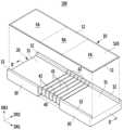
도 1 내지 도 3을 참고하면, 제1 실시예의 폴더블 표시 장치(100)는 표시 패널(10)과, 표시 패널(10)에 결합되어 표시 패널(10)을 지지하는 패널 지지부(20)를 포함한다.Referring to FIGS. 1 to 3 , the
표시 패널(10)은 가요성 기판(11)과, 가요성 기판(11) 상에 위치하는 표시부(12)를 포함한다. 표시 패널(10)은 예를 들어 유기 발광 표시 패널, 액정 표시 패널, 전기 영동 표시 패널 중 어느 하나일 수 있다.The
표시 패널(10)은 표시부(12)가 위치하는 제1면(S10)과, 제1면(S10)과 반대되는 제2면(S20)을 포함한다. 제1면(S10)은 표시면이며, 제2면(S20)은 표시면이거나 비표시면일 수 있다. 도 1을 기준으로 표시 패널(10)의 상면이 제1면(S10)이 되고, 표시 패널(10)의 하면이 제2면(S20)이 된다.The
표시 패널(10)은 평탄 영역(FA)과 벤딩 가능 영역(BA)으로 구분된다. 예를 들어, 표시 패널(10)은 중앙에 위치하는 벤딩 가능 영역(BA)과, 벤딩 가능 영역(BA)의 양측에 위치하는 두 개의 평탄 영역(FA)으로 구분될 수 있다. 제1 방향(DR1)에 따른 두 평탄 영역(FA)의 길이는 같거나 서로 다를 수 있다.The
패널 지지부(20)는 표시 패널(10)의 제2면(S20)과 마주하며 표시 패널(10)에 결합된다. 패널 지지부(20)는 두 개의 평탄 영역(FA)에 대응하는 두 개의 지지판(30)과, 벤딩 가능 영역(BA)에 대응하는 복수의 링크 부재(40)를 포함할 수 있다.The
복수의 링크 부재(40)는 제1 방향(DR1)을 따라 나란히 배열되며, 복수의 링크 부재(40) 각각은 제1 방향(DR1)과 교차하는 제2 방향(DR2)을 따라 뻗은 막대 형상일 수 있다. 단면상에서 관찰되는 복수의 링크 부재(40) 각각의 수직 폭(a1)(도 3 참조)은 지지판(30)의 수직 폭(a2)(도 3 참조)보다 작을 수 있다.The plurality of
복수의 링크 부재(40) 각각은 표시 패널(10)과 마주하는 제1 지지면(41)을 가지며, 두 개의 지지판(30) 각각은 표시 패널(10)과 마주하는 제2 지지면(31)을 가진다. 표시 패널(10)의 벤딩 가능 영역(BA)은 복수의 제1 지지면(41) 상에 위치하고, 평탄 영역(FA)은 두 개의 제2 지지면(31) 상에 위치한다. 펼침 상태에서 복수의 제1 지지면(41)과 두 개의 제2 지지면(31)은 제1 방향(DR1)을 따라 나란하며, 같은 높이에 위치한다.Each of the plurality of
표시 패널(10)의 평탄 영역(FA)은 도시하지 않은 점착층에 의해 지지판(30)의 제2 지지면(31)에 부착될 수 있다. 반면, 표시 패널(10)의 벤딩 가능 영역(BA)은 복수의 링크 부재(40)에 부착되지 않는다. 즉, 표시 패널(10)의 평탄 영역(FA)은 제2 지지면(31)에 고정되나, 벤딩 가능 영역(BA)은 복수의 제1 지지면(41)과 접촉하거나 복수의 제1 지지면(41)으로부터 살짝 떠 있는 상태를 유지할 수 있다.The flat area FA of the
복수의 링크 부재(40) 각각은 제2 방향(DR2)에 따른 양측 단부에서 위로 돌출된 제1 돌출부(42)를 포함할 수 있다. 지지판(30)은 제2 방향(DR2)에 따른 양측 단부에서 위로 돌출된 제2 돌출부(32)를 포함할 수 있다. 제1 돌출부(42)와 제2 돌출부(32)는 표시 패널(10)과 중첩되지 않으며, 표시 패널(10)의 양측 바깥에 위치할 수 있다.Each of the plurality of
여기서, '위로 돌출된'이라는 표현은 도면을 기준으로 양(+)의 제3 방향을 따라 돌출된 것을 의미하며, 이는 표시 패널(10)의 제2면(S20)으로부터 제1면(S10)을 향하는 방향을 따라 돌출된 것과 같은 의미이다.Here, the expression 'protruding upward' means protruding along the positive (+) third direction based on the drawing, which means protruding from the second surface S20 to the first surface S10 of the
복수의 제1 돌출부(42)와 두 개의 제2 돌출부(32)는 복수의 회전 결합부(50)에 의해 상호 결합된다. 복수의 회전 결합부(50) 각각은 회전축(51)을 가지며, 복수의 링크 부재(40) 각각은 제1 돌출부(42)에 위치하는 두 개의 회전축(51)을 중심으로 회전할 수 있다. 회전 결합부(50)는 예를 들어 힌지축을 가지는 힌지 조립체로 구성될 수 있다. 이 경우, 회전축(51)은 힌지축으로 이루어진다.The plurality of
도 4는 도 3에 도시한 회전 결합부의 예시를 나타낸 단면도이다.Figure 4 is a cross-sectional view showing an example of the rotational coupling shown in Figure 3.
도 4를 참고하면, 회전 결합부(50)는 어느 하나의 제1 돌출부(42)에 연결된 제1 링크 아암(52)과, 다른 하나의 제1 돌출부(42)에 연결된 제2 링크 아암(53)과, 제1 링크 아암(52)과 제2 링크 아암(53)을 관통하여 이 둘을 힌지 결합시키는 회전축(51)을 포함할 수 있다. 회전 결합부(50)는 도시한 예시로 한정되지 않는다.Referring to FIG. 4, the
다시 도 1 내지 도 3을 참고하면, 복수의 링크 부재(40) 각각은 제1 지지면(41) 아래에 위치하는 두 개의 하부 경사면(43)을 포함한다. 복수의 제1 돌출부(42) 각각은 두 개의 상부 경사면(44)을 포함한다. 상부 경사면(44)은 하부 경사면(43)과 같은 기울기를 가지며, 단면상에서 하부 경사면(43)과 동일 평면 상에 위치할 수 있다.Referring again to FIGS. 1 to 3 , each of the plurality of
회전축(51)과 회전 결합부(50)는 상부 경사면(44)의 상측 단부에 위치할 수 있다. 두 개의 회전축(51)은 제1 지지면(41)보다 높게 위치하며, 양(+)의 제3 방향(펼침 상태에서 제2면(S20)으로부터 제1면(S10)을 향하는 방향과 일치)을 따라 제1 지지면(41)으로부터 소정의 이격 거리(G1)(도 3 참조)를 가진다.The
제1 지지면(41)에 대한 회전축(51)의 이격 거리(G1)는 표시 패널(10)의 두께보다 크다. 따라서, 두 개의 회전축(51)은 표시 패널(10)의 제1면(S10)보다 높게 위치하며, 양(+)의 제3 방향(DR3)을 따라 제1면(S10)으로부터 소정의 이격 거리(G2)를 가진다.The separation distance G1 of the
또한, 각각의 링크 부재(40)에서 두 회전축(51) 사이의 거리(D)(도 3 참조)는 제1 지지면(41)의 폭(W)(도 3 참조)보다 크다. 복수의 제1 돌출부(42) 각각은 두 개의 상부 경사면(44) 상에서 상부 경사면(44)과 이어진 두 개의 수직면(45)을 포함할 수 있다.In addition, the distance D between the two
펼침 상태에서, 수직면(45)은 이웃한 제1 돌출부(42)의 수직면(45)과 접촉하고, 상부 경사면(44)은 이웃한 제1 돌출부(42)의 상부 경사면(44)과 이격된다. 복수의 제1 지지면(41)은 서로 이격되며, 하부 경사면(43)은 이웃한 링크 부재(40)의 하부 경사면(43)과 이격된다.In the unfolded state, the
펼침 상태에서, 복수의 링크 부재(40) 중 최외곽에 위치하는 링크 부재(40)의 제1 지지면(41)은 지지판(30)의 제2 지지면(31)과 이격되고, 최외곽에 위치하는 상부 경사면(44)과 하부 경사면(43)은 지지판(30)의 내면과 이격된다.In the unfolded state, the
도 5는 도 2에 도시한 폴더블 표시 장치의 폴딩 상태를 도시한 단면도이다. 도 6은 도 5의 부분 확대도이고, 도 7은 도 6의 부분 확대도이다.FIG. 5 is a cross-sectional view showing a folded state of the foldable display device shown in FIG. 2. FIG. 6 is a partially enlarged view of FIG. 5, and FIG. 7 is a partially enlarged view of FIG. 6.
도 5 내지 도 7을 참고하면, 제1 실시예의 폴더블 표시 장치(100)는 복수의 링크 부재(40)가 회전축(51)을 중심으로 회전하고, 표시 패널(10)의 벤딩 가능 영역(BA)이 원호 모양으로 구부러지면서 폴딩 상태로 전환된다. 도 5에서는 여섯 개의 링크 부재(40)가 밀착되어 단면상에서 반원을 구성하고, 표시 패널(10)의 벤딩 가능 영역(BA)이 180˚로 벤딩된 경우를 예로 들어 도시하였다.Referring to FIGS. 5 to 7 , the
폴딩 상태에서, 복수의 제1 지지면(41)은 서로 이어지고, 복수의 링크 부재(40)는 하부 경사면(43)끼리 접촉하며, 최외곽 링크 부재(40)의 하부 경사면(43)은 지지판(30)의 내면과 접촉한다. 복수의 제1 돌출부(42)는 상부 경사면(44)끼리 접촉하고, 최외곽 제1 돌출부(42)의 상부 경사면(44)은 지지판(30)의 내면과 접촉한다.In the folded state, the plurality of first support surfaces 41 are connected to each other, the lower
반면, 폴딩 상태에서 이웃한 두 개의 수직면(45)은 회전축(51)을 중심으로 벌어지며, 최외곽 제1 돌출부(42)의 수직면(45)은 지지판(30)의 내면과 이격된다. 복수의 링크 부재(40)에서 하부 경사면(43)의 각도는 폴딩 상태에서 복수의 링크 부재(40)가 서로 밀착되어 반원을 구성할 수 있는 설정된다.On the other hand, in the folded state, the two adjacent
복수의 링크 부재(40) 각각에서 두 개의 회전축(51)이 제1 지지면(41)보다 높게 위치함에 따라, 폴딩 상태에서 최외곽 링크 부재(40)의 제1 지지면(41) 가장자리는 지지판(30)의 제2 지지면(31)으로부터 벤딩 가능 영역(BA)의 곡률 중심(C)을 향해 소정의 이격 거리(G3)(도 7 참조)를 가진다. 즉, 폴딩 상태에서 제1 지지면(41)의 가장자리는 제2 지지면(31)의 가장자리와 접하지 않고, 제2 지지면(31)의 가장자리보다 벤딩 가능 영역(BA)의 곡률 중심(C)에 더 가깝게 위치한다.As the two
지지판(30)과 최외곽 링크 부재(40)를 연결하는 회전축(51)에 있어서, 회전축(51)과 제1 지지면(41) 사이의 거리(D1)(도 7 참조)는 회전축(51)과 제2 지지면(31) 사이의 거리(D2)(도 7 참조)보다 크다. 이러한 D1과 D2의 차이가 폴딩 상태에서 전술한 이격 거리(G3)로 나타난다.In the
또한, 펼침 상태에서 복수의 제1 지지면(41)은 서로 이격되어 위치한다. 이는 복수의 제1 지지면(41) 길이의 합이 펼침 상태에서 두 개의 제2 지지면(31)을 연결하는 가상 선의 길이보다 짧은 것을 의미한다. 따라서 폴딩 상태에서 서로 접하는 복수의 제1 지지면(41)은 두 개의 제2 지지면(31)을 연결하는 가상 원호(ISC)(도 6 참조)의 내측에 위치할 수 있다.Additionally, in the unfolded state, the plurality of first support surfaces 41 are positioned spaced apart from each other. This means that the sum of the lengths of the plurality of first support surfaces 41 is shorter than the length of the virtual line connecting the two second support surfaces 31 in the unfolded state. Accordingly, the plurality of first support surfaces 41 that contact each other in the folded state may be located inside the virtual circular arc (ISC) (see FIG. 6) connecting the two second support surfaces 31.
예를 들어, 이웃한 두 개의 제1 지지면(41)이 접하는 복수의 지점 중 적어도 하나의 지점은 가상 원호(ISC) 상에 위치할 수 있고, 제1 지지면(41)의 나머지 부분은 가상 원호(ISC)와 거리를 두고 가상 원호(ISC)의 내측에 위치할 수 있다. 폴딩 상태에서 벤딩 가능 영역(BA)의 제2면(S20)은 가상 원호(ISC) 상에 위치할 수 있다.For example, at least one point among the plurality of points where two neighboring first support surfaces 41 come into contact may be located on an imaginary circular arc (ISC), and the remaining portion of the
이와 같이 복수의 링크 부재(40)는 전술한 회전축(51)과 제1 지지면(41)의 높이 차이로 인해, 폴딩 상태에서 벤딩 가능 영역(BA)의 제2면(S20)으로부터 내측으로(가상 원호(ISC) 또는 벤딩 가능 영역(BA)의 곡률 중심(C)을 향하는 방향으로) 밀려나 위치한다. 따라서 복수의 링크 부재(40)는 폴딩 상태에서 표시 패널(10)의 변형을 최소화하여 표시 패널(10)의 불량 발생을 억제할 수 있다.In this way, the plurality of
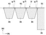
도 8은 비교예에 따른 폴더블 표시 장치의 펼침 상태를 도시한 부분 확대 단면도이고, 도 9는 도 8에 도시한 폴더블 표시 장치의 폴딩 상태를 도시한 부분 확대 단면도이다.FIG. 8 is a partially enlarged cross-sectional view showing the unfolded state of the foldable display device according to a comparative example, and FIG. 9 is a partially enlarged cross-sectional view showing the folded state of the foldable display device shown in FIG. 8.
도 8과 도 9를 참고하면, 복수의 링크 부재(401)는 회전축(51)을 가지는 복수의 회전 결합부(50)에 의해 상호 결합되며, 복수의 링크 부재(401) 각각은 두 개의 회전축(51)을 중심으로 회전할 수 있다. 펼침 상태에서 두 개의 회전축(51)은 표시 패널(10)과 마주하는 제1 지지면(411) 및 제2 지지면(311)과 같은 높이에 위치한다.Referring to Figures 8 and 9, a plurality of
이 경우, 폴딩 상태에서 이웃한 두 개의 제1 지지면(411)이 접하는 복수의 지점(P1, P2)(도 9 참조)은 두 개의 제2 지지면(311)을 연결하는 가상 원호(ISC)의 외측에 위치한다. 따라서 복수의 링크 부재(401)는 이웃한 두 개의 제1 지지면(411)이 접하는 복수의 지점(P1, P2)에서 표시 패널(10)을 가상 원호(ISC)의 곡률 중심(C)으로부터 멀어지는 방향으로 밀어 변형시킨다.In this case, the plurality of points (P1, P2) (see FIG. 9) where two neighboring first support surfaces 411 in the folded state contact each other are virtual circular arcs (ISC) connecting the two second support surfaces 311. It is located outside of. Accordingly, the plurality of
표시 패널(10)의 벤딩 가능 영역(BA)은 폴딩 상태에서 전체적으로 180˚ 구부러지면서 변형이 발생하지만, 이웃한 두 개의 제1 지지면(411)이 접하는 복수의 지점(P1, P2)에 대응하여 응력이 다른 곳보다 크게 발생한다. 이러한 현상은 표시 패널(10)을 구성하는 다층막 중 변형량에 민감한 층이 파손될 확률을 높인다.The bendable area BA of the
예를 들어, 표시 패널(10)은 가요성 기판, 표시부, 밀봉층, 터치 센서부, 편광 필름, 커버 윈도우 등의 다층막으로 구성된다. 이때 커버 윈도우의 하드 코팅층이나 표시부의 무기 절연막 등은 취성의 성질을 가지며, 인장 변형에 의해 파손될 확률이 높다. 따라서 비교예의 폴더블 표시 장치는 폴딩 상태에서 급격한 응력 상승에 의해 표시 패널(10)의 특정 층이 파손될 가능성이 크다.For example, the
반면, 제1 실시예의 폴더블 표시 장치(100)는 전술한 회전축(51)과 제1 지지면(41)의 높이 차이로 인해 폴딩 상태에서 복수의 링크 부재(40)가 표시 패널(10)을 밀어 변형시키는 양을 최소화하며, 표시 패널(10)의 파손 가능성을 낮추어 제품의 내구성을 높일 수 있다.On the other hand, in the
또한, 제1 실시예의 폴더블 표시 장치(100)에서 제1 돌출부(42)와 제2 돌출부(32)의 상면은 표시 패널(10)의 제1면(S10)보다 높게 위치한다. 즉, 펼침 상태에서 제1 돌출부(42)와 제2 돌출부(32)의 상면은 양(+)의 제3 방향(DR3)을 따라 표시 패널(10)의 제1면(S10)으로부터 이격 거리(G4)(도 2 및 도 3 참조)를 가진다.Additionally, in the
폴더블 표시 장치(100)에 낙하 충격과 같은 외부 충격이 가해지는 경우, 표시 패널(10)보다 위로 돌출된 제1 돌출부(42)와 제2 돌출부(32)에 외부 충격이 먼저 가해질 수 있다. 이 경우, 제1 돌출부(42)와 제2 돌출부(32)는 표시 패널(10)의 보호 장치로 기능하며, 외부 충격에 따른 표시 패널(10)의 파손을 억제할 수 있다.When an external shock, such as a falling shock, is applied to the
도 10은 본 발명의 제2 실시예에 따른 폴더블 표시 장치의 펼침 상태를 도시한 부분 확대 단면도이고, 도 11은 도 10에 도시한 폴더블 표시 장치의 폴딩 상태를 도시한 도면이다.FIG. 10 is a partially enlarged cross-sectional view showing the unfolded state of the foldable display device according to the second embodiment of the present invention, and FIG. 11 is a diagram showing the folded state of the foldable display device shown in FIG. 10.
도 10과 도 11을 참고하면, 제2 실시예의 폴더블 표시 장치(200)에서 복수의 제1 지지면(41) 각각은 양측 가장자리에 위치하는 두 개의 모따기면(41b)을 포함한다.Referring to FIGS. 10 and 11 , in the
구체적으로, 복수의 제1 지지면(41) 각각은 펼침 상태에서 제1 방향(DR1)과 나란한 중앙면(41a)과, 중앙면(41a)의 양측에 위치하는 두 개의 모따기면(41b)을 포함할 수 있다. 두 모따기면(41b)의 폭은 서로 같을 수 있고, 두 모따기면(41b)의 모따기 각은 서로 같을 수 있다. 이 경우 복수의 제1 지지면(41) 각각은 좌우 대칭을 이룬다.Specifically, each of the plurality of first support surfaces 41 has a
복수의 제1 지지면(41) 각각이 두 개의 모따기면(41b)을 포함함에 따라, 폴딩 상태에서 이웃한 두 개의 제1 지지면(41)이 접하는 복수의 지점은 전술한 제1 실시예의 경우보다 벤딩 가능 영역(BA)의 곡률 중심(C)에 더 가깝게 위치한다.As each of the plurality of first support surfaces 41 includes two chamfered
즉, 제1 실시예의 경우 폴딩 상태에서 이웃한 두 개의 제1 지지면(41)은 P3 지점(도 11 참조)에서 접한다. 그러나 제2 실시예의 경우 폴딩 상태에서 이웃한 두 개의 제1 지지면(41)은 P4 지점(도 11 참조)에서 접한다. P4 지점은 P3 지점보다 벤딩 가능 영역(BA)의 곡률 중심(C)에 더 가깝게 위치한다.That is, in the case of the first embodiment, in the folded state, the two adjacent first support surfaces 41 contact at point P3 (see FIG. 11). However, in the case of the second embodiment, in the folded state, the two adjacent first support surfaces 41 contact at point P4 (see FIG. 11). Point P4 is located closer to the center of curvature (C) of the bendable area (BA) than point P3.
제2 실시예의 폴더블 표시 장치(200)는 P3 지점과 P4 지점 사이의 거리(G5)(도 11 참조)만큼 링크 부재(40)의 제1 지지면(41)을 표시 패널(10)로부터 이격시킬 수 있다. 따라서 복수의 링크 부재(40)는 폴딩 상태에서 표시 패널(10)에 실질적인 변형을 가하지 않으며, 표시 패널(10)의 응력 발생을 최소화할 수 있다.The
제2 실시예의 폴더블 표시 장치(200)는 복수의 링크 부재(40) 각각의 제1 지지면(41)이 두 개의 모따기면(41b)을 포함하는 것을 제외하고, 전술한 제1 실시예와 동일 또는 유사한 구성으로 이루어진다.The
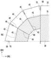
도 12는 본 발명의 제3 실시예에 따른 폴더블 표시 장치의 펼침 상태를 도시한 단면도이고, 도 13은 도 12에 도시한 폴더블 표시 장치의 폴딩 상태를 도시한 부분 확대도이다.FIG. 12 is a cross-sectional view showing the unfolded state of the foldable display device according to the third embodiment of the present invention, and FIG. 13 is a partial enlarged view showing the folded state of the foldable display device shown in FIG. 12.
도 12와 도 13을 참고하면, 제3 실시예의 폴더블 표시 장치(300)에서 패널 지지부(20)는 복수의 링크 부재(40) 사이에 위치하는 중앙 지지판(60)을 포함한다. 중앙 지지판(60)은 패널 지지부(20)의 중심에 위치하며, 복수의 링크 부재(40)와 두 개의 지지판(30)은 중앙 지지판(60)을 중심에 두고 좌우 대칭으로 배치될 수 있다.Referring to FIGS. 12 and 13 , in the
중앙 지지판(60)은 표시 패널(10)과 마주하는 제3 지지면(61)을 포함하며, 제2 방향(DR2)에 따른 양측 단부에서 위로 돌출된 제3 돌출부(62)를 포함한다.The
복수의 제1 돌출부(42)와 두 개의 제2 돌출부(32) 및 하나의 제3 돌출부(62)는 복수의 회전 결합부(50)에 의해 상호 결합된다. 복수의 회전 결합부(50) 각각은 회전축(51)을 가지며, 복수의 링크 부재(40) 각각은 제1 돌출부(42)에 위치하는 두 개의 회전축(51)을 중심으로 회전할 수 있다.The plurality of
폴딩 상태에서, 복수의 링크 부재(40)는 하부 경사면(43)이 서로 접하도록 밀착되며, 복수의 제1 지지면(41)은 지지판(30)과 중앙 지지판(60) 사이에서 90˚ 의 원호에 대응한다. 표시 패널(10)은 중앙 지지판(60) 및 두 개의 지지판(30)에 대응하는 세 개의 평탄 영역(FA)과, 복수의 링크 부재(40)에 대응하는 두 개의 벤딩 가능 영역(BA)으로 구분될 수 있다.In the folded state, the plurality of
제3 실시예의 폴더블 표시 장치(300)는 복수의 링크 부재(40) 사이에 중앙 지지판(60)이 위치하는 것을 제외하고 전술한 제1 실시예와 동일 또는 유사한 구성으로 이루어진다.The
도 14는 본 발명의 제4 실시예에 따른 폴더블 표시 장치의 폴딩 상태를 도시한 부분 확대 단면도이다.Figure 14 is a partially enlarged cross-sectional view showing the folded state of the foldable display device according to the fourth embodiment of the present invention.
도 14를 참고하면, 제4 실시예의 폴더블 표시 장치(400)에서 복수의 제1 지지면(41) 각각은 양측 가장자리에 위치하는 두 개의 모따기면(41b)을 포함한다. 즉, 복수의 제1 지지면(41) 각각은 펼침 상태에서 제1 방향(DR1)과 나란한 중앙면(41a)과, 중앙면(41a)의 양측에 위치하는 두 개의 모따기면(41b)을 포함한다.Referring to FIG. 14, in the
모따기면(41b)의 작용은 전술한 제2 실시예에서 설명한 것과 동일하다. 제4 실시예의 폴더블 표시 장치(400)는 복수의 제1 지지면(41) 각각이 두 개의 모따기면(41b)을 포함하는 것을 제외하고, 전술한 제3 실시예와 동일 또는 유사한 구성으로 이루어진다.The action of the chamfered
상기에서는 본 발명의 바람직한 실시예에 대하여 설명하였지만, 본 발명은 이에 한정되는 것이 아니고 특허청구범위와 발명의 상세한 설명 및 첨부한 도면의 범위 안에서 여러 가지로 변형하여 실시하는 것이 가능하고 이 또한 본 발명의 범위에 속하는 것은 당연하다.Although the preferred embodiment of the present invention has been described above, the present invention is not limited thereto, and can be implemented with various modifications within the scope of the claims, the detailed description of the invention, and the accompanying drawings, and this is also the present invention. It is natural that it falls within the scope of .
100, 200, 300, 400: 폴더블 표시 장치
10: 표시 패널11: 가요성 기판
12: 표시부S10: 제1면
S20: 제2면20: 패널 지지부
30: 지지판31: 제2 지지면
32: 제2 돌출부40: 링크 부재
41: 제1 지지면41b: 모따기면
42: 제1 돌출부50: 회전 결합부
51: 회전축60: 중앙 지지판
61: 제3 지지면62: 제3 돌출부100, 200, 300, 400: Foldable display device
10: Display panel 11: Flexible substrate
12: display S10: first page
S20: Second side 20: Panel support
30: support plate 31: second support surface
32: second protrusion 40: link member
41:
42: first protrusion 50: rotational coupling portion
51: rotation axis 60: central support plate
61: third support surface 62: third protrusion
Claims (22)
Translated fromKorean상기 제2면과 마주하며 상기 표시 패널에 결합된 패널 지지부를 포함하고,
상기 패널 지지부는,
상기 벤딩 가능 영역에 대응하여 제1 방향을 따라 나란하게 배열되고, 각각 상기 표시 패널과 마주하는 제1 지지면을 가지며, 각각 두 개의 회전축을 중심으로 회전 가능하게 결합된 복수의 링크 부재, 및
상기 2개의 평탄 영역에 대응하고, 각각 상기 표시 패널과 마주하는 제2 지지면을 포함하는 2개의 지지판을 포함하고,
상기 복수의 링크 부재 각각의 상기 두 개의 회전축은 상기 제2면으로부터 상기 제1면을 향하는 방향을 따라 상기 제1 지지면과 이격되어 있고,
상기 복수의 링크 부재 중 상기 평탄 영역과 이웃하는 최외곽 링크부재의 상기 제1 지지면은, 폴딩 상태에서 상기 제2 지지면으로부터 상기 벤딩 가능 영역의 곡률 중심을 향하는 방향으로 제1 거리와 제2 거리 사이의 거리차이 만큼 이격되어 있고,
상기 제1 거리는 상기 회전축과 상기 제1 지지면 사이의 거리이고,
상기 제2 거리는 상기 회전축과 상기 제2 지지면 사이의 거리인 폴더블 표시 장치.A display panel having a first surface on which a display unit is located, a second surface on an opposite side of the first surface, and including a bendable area and two flat areas located on both sides of the bendable area, and
a panel support part facing the second surface and coupled to the display panel;
The panel support part,
A plurality of link members arranged side by side in a first direction corresponding to the bendable area, each having a first support surface facing the display panel, and each link member rotatably coupled about two rotation axes, and
comprising two support plates corresponding to the two flat areas and each including a second support surface facing the display panel;
The two rotation axes of each of the plurality of link members are spaced apart from the first support surface along a direction from the second surface to the first surface,
Among the plurality of link members, the first support surface of the outermost link member adjacent to the flat area has a first distance and a second distance from the second support surface in a direction toward the center of curvature of the bendable area in a folded state. They are separated by the distance difference between the streets,
The first distance is the distance between the rotation axis and the first support surface,
The second distance is a distance between the rotation axis and the second support surface.
상기 복수의 링크 부재가 포함하는 복수의 제1 지지면은 펼침 상태에서 서로 이격되고,
상기 복수의 링크 부재 각각의 상기 두 개의 회전축 사이의 거리는 상기 제1 지지면의 폭보다 큰 폴더블 표시 장치.According to paragraph 1,
The plurality of first support surfaces included in the plurality of link members are spaced apart from each other in the unfolded state,
A foldable display device in which a distance between the two rotation axes of each of the plurality of link members is greater than a width of the first support surface.
상기 복수의 링크 부재 각각은,
상기 제1 지지면의 양측 단부 아래에 위치하며 상기 제1 지지면과 연결되는 두 개의 하부 경사면, 그리고
상기 제1 방향과 교차하는 제2 방향에 따른 상기 제1 지지면의 양측 단부에 위치하는 두 개의 제1 돌출부
를 포함하는 폴더블 표시 장치.According to paragraph 2,
Each of the plurality of link members,
Two lower inclined surfaces located below both ends of the first support surface and connected to the first support surface, and
Two first protrusions located at both ends of the first support surface along a second direction intersecting the first direction
A foldable display device including a.
상기 두 개의 제1 돌출부 각각은 단면상에서 상기 두 개의 하부 경사면과 동일 평면 상에 위치하는 두 개의 상부 경사면을 포함하고,
상기 두 개의 회전축은 상기 두 개의 상부 경사면의 상측 단부에 위치하는 폴더블 표시 장치.According to paragraph 3,
Each of the two first protrusions includes two upper inclined surfaces located on the same plane as the two lower inclined surfaces in cross-section,
The two rotation axes are located at upper ends of the two upper inclined surfaces.
상기 두 개의 제1 돌출부 각각은 상기 두 개의 상부 경사면 상에 위치하는 두 개의 수직면을 더 포함하고,
펼침 상태에서, 상기 두 개의 수직면은 상기 제1 방향을 따라 이웃한 상기 제1 돌출부가 포함하는 상기 수직면과 접촉하는 폴더블 표시 장치.According to paragraph 4,
Each of the two first protrusions further includes two vertical surfaces located on the two upper inclined surfaces,
In the unfolded state, the two vertical surfaces are in contact with the vertical surface including the adjacent first protrusion along the first direction.
폴딩 상태에서, 상기 복수의 제1 지지면은 서로 이어지고, 상기 두 개의 하부 경사면은 이웃한 상기 링크 부재의 상기 하부 경사면에 밀착되며, 상기 벤딩 가능 영역은 원호 모양으로 벤딩되는 폴더블 표시 장치.According to paragraph 4,
In a folded state, the plurality of first support surfaces are connected to each other, the two lower inclined surfaces are in close contact with the lower inclined surfaces of the adjacent link members, and the bendable area is bent in an arc shape.
상기 두 개의 지지판 각각은 상기 표시 패널과 마주하는 제2 지지면과, 상기 제2 방향에 따른 상기 제2 지지면의 양측 단부에 위치하는 두 개의 제2 돌출부를 포함하며,
상기 두 개의 제2 돌출부와 상기 복수의 링크 부재가 포함하는 복수의 제1 돌출부는 상기 회전축을 가지는 회전 결합부에 의해 상호 결합되는 폴더블 표시 장치.According to paragraph 4,
Each of the two support plates includes a second support surface facing the display panel and two second protrusions located at both ends of the second support surface in the second direction,
A foldable display device in which the two second protrusions and the plurality of first protrusions included in the plurality of link members are coupled to each other by a rotation coupler having the rotation axis.
펼침 상태에서, 상기 두 개의 제2 지지면은 상기 복수의 제1 지지면과 나란하고,
폴딩 상태에서, 상기 복수의 제1 지지면 중 최외곽 제1 지지면의 가장자리는 상기 제2 지지면으로부터 상기 벤딩 가능 영역의 곡률 중심을 향해 이격되는 폴더블 표시 장치.According to clause 8,
In the unfolded state, the two second support surfaces are parallel to the plurality of first support surfaces,
In a folded state, the edge of the outermost first support surface among the plurality of first support surfaces is spaced apart from the second support surface toward the center of curvature of the bendable area.
폴딩 상태에서, 상기 복수의 제1 지지면은 상기 두 개의 제2 지지면을 연결하는 가상 원호의 내측에 위치하는 폴더블 표시 장치.According to clause 9,
In a folded state, the plurality of first support surfaces are located inside a virtual arc connecting the two second support surfaces.
상기 두 개의 제2 돌출부는 상기 표시 패널의 양측 바깥에서 서로 마주하며 위치하고,
상기 복수의 제1 돌출부는 상기 표시 패널의 양측 바깥에서 서로 마주하며 위치하는 폴더블 표시 장치.According to clause 8,
The two second protrusions are located facing each other outside both sides of the display panel,
A foldable display device where the plurality of first protrusions face each other outside both sides of the display panel.
상기 제1 돌출부의 상면과 상기 제2 돌출부의 상면은 상기 제2면으로부터 상기 제1면을 향하는 방향을 따라 상기 제1면으로부터 이격되어 있는 폴더블 표시 장치.According to clause 8,
A top surface of the first protrusion and a top surface of the second protrusion are spaced apart from the first surface along a direction from the second surface toward the first surface.
상기 복수의 제1 지지면 각각은 중앙면과, 상기 중앙면의 양측에 위치하는 두 개의 모따기면을 포함하는 폴더블 표시 장치.According to paragraph 4,
Each of the plurality of first support surfaces includes a central surface and two chamfered surfaces located on both sides of the central surface.
상기 두 개의 모따기면은 서로 같은 폭과 서로 같은 모따기 각을 가지는 폴더블 표시 장치.According to clause 13,
A foldable display device wherein the two chamfered surfaces have the same width and the same chamfer angle.
상기 패널 지지부는 중앙 지지판을 더 포함하며,
상기 복수의 링크 부재는 상기 중앙 지지판의 양측에 위치하는 폴더블 표시 장치.According to clause 8,
The panel support further includes a central support plate,
A foldable display device wherein the plurality of link members are located on both sides of the central support plate.
상기 중앙 지지판은 상기 표시 패널과 마주하는 제3 지지면과, 상기 제2 방향에 따른 상기 제3 지지면의 양측 단부에 위치하는 두 개의 제3 돌출부를 포함하고,
상기 두 개의 제3 돌출부와 상기 복수의 제1 돌출부는 상기 회전축을 가지는 회전 결합부에 의해 상호 결합되는 폴더블 표시 장치.According to clause 15,
The central support plate includes a third support surface facing the display panel and two third protrusions located at both ends of the third support surface in the second direction,
A foldable display device in which the two third protrusions and the plurality of first protrusions are coupled to each other by a rotation coupler having the rotation axis.
펼침 상태에서, 상기 제3 지지면은 상기 복수의 제1 지지면과 나란하고,
폴딩 상태에서, 상기 복수의 제1 지지면 중 상기 제3 지지면과 접하는 상기 제1 지지면의 가장자리는 상기 제3 지지면으로부터 상기 벤딩 가능 영역의 곡률 중심을 향해 이격되는 폴더블 표시 장치.According to clause 16,
In the unfolded state, the third support surface is parallel to the plurality of first support surfaces,
In a folded state, an edge of the first support surface in contact with the third support surface among the plurality of first support surfaces is spaced apart from the third support surface toward the center of curvature of the bendable area.
폴딩 상태에서, 상기 복수의 제1 지지면은 상기 제2 지지면과 상기 제3 지지면을 연결하는 가상 원호의 내측에 위치하는 폴더블 표시 장치.According to clause 17,
In a folded state, the plurality of first support surfaces are located inside a virtual arc connecting the second support surface and the third support surface.
상기 복수의 제1 지지면 각각은 중앙면과, 상기 중앙면의 양측에 위치하는 두 개의 모따기면을 포함하는 폴더블 표시 장치.According to clause 15,
Each of the plurality of first support surfaces includes a central surface and two chamfered surfaces located on both sides of the central surface.
상기 두 개의 모따기면은 서로 같은 폭과 서로 같은 모따기 각을 가지는 폴더블 표시 장치.According to clause 19,
A foldable display device wherein the two chamfered surfaces have the same width and the same chamfer angle.
Priority Applications (6)
| Application Number | Priority Date | Filing Date | Title |
|---|---|---|---|
| KR1020160129963AKR102628024B1 (en) | 2016-10-07 | 2016-10-07 | Foldable display device |
| US15/672,721US10198041B2 (en) | 2016-10-07 | 2017-08-09 | Foldable display device |
| EP17190634.0AEP3306596B1 (en) | 2016-10-07 | 2017-09-12 | Foldable display device |
| TW106131244ATWI746635B (en) | 2016-10-07 | 2017-09-12 | Foldable display device |
| CN201710897064.XACN107919062B (en) | 2016-10-07 | 2017-09-28 | Foldable display device |
| JP2017193343AJP7048243B2 (en) | 2016-10-07 | 2017-10-03 | Foldable display device |
Applications Claiming Priority (1)
| Application Number | Priority Date | Filing Date | Title |
|---|---|---|---|
| KR1020160129963AKR102628024B1 (en) | 2016-10-07 | 2016-10-07 | Foldable display device |
Publications (2)
| Publication Number | Publication Date |
|---|---|
| KR20180039220A KR20180039220A (en) | 2018-04-18 |
| KR102628024B1true KR102628024B1 (en) | 2024-01-22 |
Family
ID=59895090
Family Applications (1)
| Application Number | Title | Priority Date | Filing Date |
|---|---|---|---|
| KR1020160129963AActiveKR102628024B1 (en) | 2016-10-07 | 2016-10-07 | Foldable display device |
Country Status (6)
| Country | Link |
|---|---|
| US (1) | US10198041B2 (en) |
| EP (1) | EP3306596B1 (en) |
| JP (1) | JP7048243B2 (en) |
| KR (1) | KR102628024B1 (en) |
| CN (1) | CN107919062B (en) |
| TW (1) | TWI746635B (en) |
Families Citing this family (55)
| Publication number | Priority date | Publication date | Assignee | Title |
|---|---|---|---|---|
| US10481634B2 (en)* | 2017-01-10 | 2019-11-19 | Lenovo (Singapore) Pte. Ltd. | Portable information device |
| KR102379216B1 (en)* | 2017-04-24 | 2022-03-28 | 삼성디스플레이 주식회사 | Display apparatus |
| KR102402183B1 (en)* | 2017-09-29 | 2022-05-27 | 엘지디스플레이 주식회사 | Foldable Display Device |
| KR102583233B1 (en)* | 2018-02-12 | 2023-09-26 | 삼성디스플레이 주식회사 | Foldable display device |
| TWI664475B (en)* | 2018-04-30 | 2019-07-01 | 友達光電股份有限公司 | Flexible display |
| US10534400B2 (en)* | 2018-05-24 | 2020-01-14 | Innolux Corporation | Foldable electronic device |
| CN108738258B (en)* | 2018-05-28 | 2019-11-15 | 武汉华星光电半导体显示技术有限公司 | Bent mobile terminal |
| CN108831301B (en)* | 2018-06-15 | 2021-04-27 | 云谷(固安)科技有限公司 | Flexible display screen and flexible display device |
| CN108665812B (en)* | 2018-06-28 | 2020-12-29 | 上海天马有机发光显示技术有限公司 | A bending device and display device |
| KR102623425B1 (en)* | 2018-07-10 | 2024-01-11 | 삼성디스플레이 주식회사 | Display apparatus |
| CN109256410A (en)* | 2018-07-28 | 2019-01-22 | 关军 | display panel and OLED display screen |
| KR102512482B1 (en)* | 2018-07-31 | 2023-03-21 | 엘지디스플레이 주식회사 | Foldable Display |
| CN109065588B (en)* | 2018-08-09 | 2021-07-13 | 上海天马有机发光显示技术有限公司 | OLED display panel and OLED display device |
| CN109300857A (en)* | 2018-08-30 | 2019-02-01 | 武汉华星光电半导体显示技术有限公司 | OLED display device |
| US10890949B2 (en)* | 2018-10-12 | 2021-01-12 | Google Llc | Hinge mechanism by gear set with slider for foldable display device |
| CN109559639B (en)* | 2018-11-29 | 2022-04-05 | 广州国显科技有限公司 | Display panel and display device |
| CN109285459B (en)* | 2018-11-29 | 2020-10-27 | 上海天马微电子有限公司 | Foldable display panel's backup pad and foldable display device |
| CN109300403B (en)* | 2018-11-30 | 2021-07-09 | 上海天马有机发光显示技术有限公司 | A foldable display device |
| CN109523921B (en)* | 2018-12-12 | 2021-07-23 | 上海天马有机发光显示技术有限公司 | Flexible display panel and display device |
| KR102643282B1 (en)* | 2019-01-16 | 2024-03-05 | 삼성디스플레이 주식회사 | Display device |
| KR20190020303A (en)* | 2019-02-10 | 2019-02-28 | 심성구 | Foldable Devices for Display |
| CN109830185B (en)* | 2019-02-22 | 2024-05-17 | 华为技术有限公司 | Folding component and folding display terminal |
| CN111696437B (en)* | 2019-03-13 | 2022-06-21 | 深圳市长盈精密技术股份有限公司 | Hinge assembly and foldable display device |
| KR102720609B1 (en) | 2019-07-19 | 2024-10-24 | 삼성디스플레이 주식회사 | Flexible display device |
| TWI724807B (en)* | 2019-07-24 | 2021-04-11 | 友達光電股份有限公司 | Flexible apparatus |
| KR102668484B1 (en)* | 2019-07-29 | 2024-05-24 | 삼성디스플레이 주식회사 | Display device |
| CN110649070A (en)* | 2019-09-03 | 2020-01-03 | 武汉华星光电半导体显示技术有限公司 | Flexible substrate, flexible display panel and manufacturing method of flexible substrate |
| KR102664582B1 (en)* | 2019-09-09 | 2024-05-16 | 삼성디스플레이 주식회사 | Foldable display device |
| KR20210033696A (en) | 2019-09-19 | 2021-03-29 | 엘지디스플레이 주식회사 | Display device |
| KR102811864B1 (en)* | 2019-09-24 | 2025-05-26 | 삼성디스플레이 주식회사 | Display device |
| KR20210044337A (en) | 2019-10-14 | 2021-04-23 | 삼성디스플레이 주식회사 | Display apparatus |
| JP6884189B2 (en)* | 2019-10-29 | 2021-06-09 | レノボ・シンガポール・プライベート・リミテッド | Portable information devices and their manufacturing methods |
| CN113614816B (en)* | 2019-11-08 | 2023-12-08 | 京东方科技集团股份有限公司 | Array substrate, manufacturing method thereof, display panel and display device |
| CN114945966A (en)* | 2020-01-10 | 2022-08-26 | 株式会社半导体能源研究所 | Angle adjusting device, supporting tool and display device |
| CN111292625B (en)* | 2020-02-28 | 2022-07-08 | 合肥维信诺科技有限公司 | Flexible display panel and display device |
| KR20210143982A (en)* | 2020-05-20 | 2021-11-30 | 삼성디스플레이 주식회사 | Display device |
| CN111739423B (en)* | 2020-06-30 | 2022-05-31 | 武汉华星光电半导体显示技术有限公司 | Support film and display module |
| KR20220007751A (en)* | 2020-07-09 | 2022-01-19 | 삼성디스플레이 주식회사 | Display device |
| KR102278840B1 (en)* | 2020-08-31 | 2021-07-16 | 정민우 | Foldable display device |
| CN120265047A (en)* | 2020-09-24 | 2025-07-04 | 京东方科技集团股份有限公司 | Display panel and manufacturing method thereof, display device and spliced display device |
| KR20220065146A (en) | 2020-11-12 | 2022-05-20 | 삼성디스플레이 주식회사 | Display device |
| KR20220065145A (en)* | 2020-11-12 | 2022-05-20 | 삼성디스플레이 주식회사 | Display device |
| KR20220077953A (en)* | 2020-12-02 | 2022-06-10 | 삼성디스플레이 주식회사 | Display device |
| CN112908174B (en)* | 2021-02-02 | 2022-07-12 | 武汉华星光电半导体显示技术有限公司 | Display device |
| WO2022211362A1 (en) | 2021-03-31 | 2022-10-06 | 삼성디스플레이 주식회사 | Display device and manufacturing method therefor |
| CN115527443A (en)* | 2021-06-24 | 2022-12-27 | 乐金显示有限公司 | Buffer plate and display device including the same |
| CN113674625B (en)* | 2021-08-19 | 2023-05-16 | 京东方科技集团股份有限公司 | Support piece, flexible display module and display device |
| WO2023044750A1 (en)* | 2021-09-24 | 2023-03-30 | Boe Technology Group Co., Ltd. | Pivotable support apparatus and display apparatus |
| CN113920877B (en)* | 2021-10-20 | 2023-11-28 | 武汉华星光电半导体显示技术有限公司 | Display panel and display terminal |
| KR20230063998A (en)* | 2021-11-01 | 2023-05-10 | 삼성디스플레이 주식회사 | Window and electronic device including the same |
| CN114141146B (en)* | 2021-12-02 | 2024-01-19 | 云谷(固安)科技有限公司 | Support assembly and display device |
| CN115013653B (en)* | 2022-05-26 | 2024-07-26 | 上海天马微电子有限公司 | Support assembly and display device |
| CN114697435B (en)* | 2022-06-02 | 2022-10-18 | 荣耀终端有限公司 | Folding assembly and terminal equipment |
| WO2024013844A1 (en)* | 2022-07-12 | 2024-01-18 | シャープディスプレイテクノロジー株式会社 | Foldable display |
| CN115116337A (en)* | 2022-07-25 | 2022-09-27 | 昆山国显光电有限公司 | Supporting assembly and display device |
Family Cites Families (32)
| Publication number | Priority date | Publication date | Assignee | Title |
|---|---|---|---|---|
| CN2374896Y (en)* | 1998-12-24 | 2000-04-19 | 宏桦国际股份有限公司 | Device for combining CPU and radiator |
| EP1565900B1 (en) | 2002-11-21 | 2013-04-10 | Creator Technology B.V. | Flexible display |
| TWI275863B (en) | 2005-02-22 | 2007-03-11 | Fujitsu Ltd | Flexible substrate being able to prevent plastic deformation and flexible image display |
| KR20070016475A (en)* | 2005-08-04 | 2007-02-08 | 삼성전자주식회사 | LCD Display |
| TWI370419B (en)* | 2006-10-31 | 2012-08-11 | Creator Technology Bv | Flexible display supported by hinged frame |
| JP2010218102A (en)* | 2009-03-16 | 2010-09-30 | Sony Corp | Electronic equipment |
| TWI424385B (en) | 2009-03-18 | 2014-01-21 | Prime View Int Co Ltd | Flexible display device |
| US8804324B2 (en)* | 2011-06-03 | 2014-08-12 | Microsoft Corporation | Flexible display overcenter assembly |
| US9176535B2 (en)* | 2011-06-03 | 2015-11-03 | Microsoft Technology Licensing, Llc | Flexible display flexure assembly |
| EP2540188B1 (en)* | 2011-07-01 | 2013-11-27 | Richemont International S.A. | Dispositif de fixation de bracelets |
| EP2546720B1 (en) | 2011-07-11 | 2018-09-26 | Samsung Electronics Co., Ltd. | Flexible display with display support |
| KR101386220B1 (en)* | 2012-06-26 | 2014-04-17 | 삼성디스플레이 주식회사 | A flexible display device |
| KR101452871B1 (en)* | 2013-01-11 | 2014-10-22 | (주) 프렉코 | Foldable Flexible Display Device |
| KR101663728B1 (en)* | 2013-08-26 | 2016-10-07 | 삼성전자주식회사 | foldable electronic device having flexible display |
| KR101547640B1 (en)* | 2013-09-16 | 2015-08-27 | (주) 프렉코 | Foldable flexible display device with guide device |
| GB2520271A (en)* | 2013-11-13 | 2015-05-20 | Nokia Corp | An apparatus and method of providing an apparatus comprising a bendable portion |
| CN106030688B (en)* | 2013-12-24 | 2020-01-24 | 飞利斯有限公司 | flexible electronics |
| KR102251081B1 (en) | 2014-02-05 | 2021-05-13 | 삼성디스플레이 주식회사 | Flexible display apparatus |
| KR101727971B1 (en)* | 2014-02-21 | 2017-04-18 | 삼성전자주식회사 | Foldable device |
| CN106463079B (en) | 2014-05-06 | 2019-05-14 | 株式会社半导体能源研究所 | Electronic equipment |
| CN203858554U (en)* | 2014-05-12 | 2014-10-01 | 联想(北京)有限公司 | Protective case for tablet computers |
| KR102015398B1 (en) | 2014-07-16 | 2019-08-29 | 엘지디스플레이 주식회사 | Foldable display apparatus |
| KR102263917B1 (en) | 2014-08-06 | 2021-06-11 | 엘지디스플레이 주식회사 | Foldable display apparatus |
| KR102233119B1 (en)* | 2014-09-23 | 2021-03-30 | 삼성디스플레이 주식회사 | Display device |
| KR20190006101A (en)* | 2014-10-28 | 2019-01-16 | 가부시키가이샤 한도오따이 에네루기 켄큐쇼 | Light-emitting device and electronic device |
| KR102281845B1 (en) | 2014-11-11 | 2021-07-26 | 삼성디스플레이 주식회사 | Apparatus for supporting display panel |
| KR101706321B1 (en) | 2014-11-19 | 2017-03-13 | 주식회사 세네카 | Hinge device |
| KR102471237B1 (en)* | 2015-01-21 | 2022-11-28 | 삼성디스플레이 주식회사 | Folderable display device |
| CN104851369B (en) | 2015-06-12 | 2017-11-14 | 京东方科技集团股份有限公司 | A kind of flexible display panels and its driving method, display device |
| CN106468936A (en)* | 2015-08-14 | 2017-03-01 | 联想(北京)有限公司 | Warp architecture and electronic equipment |
| US10063677B2 (en) | 2016-03-18 | 2018-08-28 | Motorola Mobility Llc | Electronic device with flexible display and hinged housing, and corresponding systems and methods |
| KR102379216B1 (en)* | 2017-04-24 | 2022-03-28 | 삼성디스플레이 주식회사 | Display apparatus |
- 2016
- 2016-10-07KRKR1020160129963Apatent/KR102628024B1/enactiveActive
- 2017
- 2017-08-09USUS15/672,721patent/US10198041B2/enactiveActive
- 2017-09-12TWTW106131244Apatent/TWI746635B/enactive
- 2017-09-12EPEP17190634.0Apatent/EP3306596B1/enactiveActive
- 2017-09-28CNCN201710897064.XApatent/CN107919062B/enactiveActive
- 2017-10-03JPJP2017193343Apatent/JP7048243B2/enactiveActive
Also Published As
| Publication number | Publication date |
|---|---|
| US10198041B2 (en) | 2019-02-05 |
| US20180101200A1 (en) | 2018-04-12 |
| TWI746635B (en) | 2021-11-21 |
| CN107919062A (en) | 2018-04-17 |
| JP7048243B2 (en) | 2022-04-05 |
| JP2018060201A (en) | 2018-04-12 |
| CN107919062B (en) | 2022-01-14 |
| EP3306596A1 (en) | 2018-04-11 |
| EP3306596B1 (en) | 2021-07-21 |
| KR20180039220A (en) | 2018-04-18 |
| TW201814367A (en) | 2018-04-16 |
Similar Documents
| Publication | Publication Date | Title |
|---|---|---|
| KR102628024B1 (en) | Foldable display device | |
| KR102716181B1 (en) | Foldable display device | |
| KR102781348B1 (en) | Display device | |
| US10959341B2 (en) | Display device | |
| KR102688971B1 (en) | Foldable display device | |
| KR102583233B1 (en) | Foldable display device | |
| US20250199349A1 (en) | Flexible display device | |
| KR102370015B1 (en) | Display apparatus | |
| TWI664475B (en) | Flexible display | |
| CN107301821A (en) | foldable display screen and display device | |
| US20220206537A1 (en) | Substrate for display | |
| KR102123997B1 (en) | Flexible display | |
| TW201401240A (en) | Flexible display device | |
| CN115842883B (en) | Folding component of electronic equipment and electronic equipment | |
| US20220071032A1 (en) | Display device | |
| US12443234B2 (en) | Display device | |
| US20230280790A1 (en) | Display device |
Legal Events
| Date | Code | Title | Description |
|---|---|---|---|
| PA0109 | Patent application | Patent event code:PA01091R01D Comment text:Patent Application Patent event date:20161007 | |
| PG1501 | Laying open of application | ||
| A201 | Request for examination | ||
| PA0201 | Request for examination | Patent event code:PA02012R01D Patent event date:20210914 Comment text:Request for Examination of Application Patent event code:PA02011R01I Patent event date:20161007 Comment text:Patent Application | |
| E902 | Notification of reason for refusal | ||
| PE0902 | Notice of grounds for rejection | Comment text:Notification of reason for refusal Patent event date:20230407 Patent event code:PE09021S01D | |
| E701 | Decision to grant or registration of patent right | ||
| PE0701 | Decision of registration | Patent event code:PE07011S01D Comment text:Decision to Grant Registration Patent event date:20231026 | |
| GRNT | Written decision to grant | ||
| PR0701 | Registration of establishment | Comment text:Registration of Establishment Patent event date:20240117 Patent event code:PR07011E01D | |
| PR1002 | Payment of registration fee | Payment date:20240117 End annual number:3 Start annual number:1 | |
| PG1601 | Publication of registration |