KR102625976B1 - Gate driver capable of stably operating at multiple frequencies - Google Patents
Gate driver capable of stably operating at multiple frequenciesDownload PDFInfo
- Publication number
- KR102625976B1 KR102625976B1KR1020220065647AKR20220065647AKR102625976B1KR 102625976 B1KR102625976 B1KR 102625976B1KR 1020220065647 AKR1020220065647 AKR 1020220065647AKR 20220065647 AKR20220065647 AKR 20220065647AKR 102625976 B1KR102625976 B1KR 102625976B1
- Authority
- KR
- South Korea
- Prior art keywords
- switching element
- low voltage
- signal
- node
- shift register
- Prior art date
- Legal status (The legal status is an assumption and is not a legal conclusion. Google has not performed a legal analysis and makes no representation as to the accuracy of the status listed.)
- Active
Links
- 230000000873masking effectEffects0.000claimsdescription84
- 230000005540biological transmissionEffects0.000claimsdescription13
- 239000003990capacitorSubstances0.000claimsdescription7
- 230000008054signal transmissionEffects0.000claimsdescription3
- 239000010409thin filmSubstances0.000description23
- 238000010586diagramMethods0.000description8
- 229910021417amorphous siliconInorganic materials0.000description4
- 238000000034methodMethods0.000description4
- 230000008859changeEffects0.000description3
- 230000008569processEffects0.000description3
- XUIMIQQOPSSXEZ-UHFFFAOYSA-NSiliconChemical compound[Si]XUIMIQQOPSSXEZ-UHFFFAOYSA-N0.000description2
- 150000001875compoundsChemical class0.000description2
- 230000000694effectsEffects0.000description2
- 230000014509gene expressionEffects0.000description2
- 229910021420polycrystalline siliconInorganic materials0.000description2
- 230000004044responseEffects0.000description2
- 239000004065semiconductorSubstances0.000description2
- 229910052710siliconInorganic materials0.000description2
- 239000010703siliconSubstances0.000description2
- 230000009471actionEffects0.000description1
- 230000008901benefitEffects0.000description1
- 210000002858crystal cellAnatomy0.000description1
- 238000002425crystallisationMethods0.000description1
- 230000008025crystallizationEffects0.000description1
- 238000007599dischargingMethods0.000description1
- 239000004973liquid crystal related substanceSubstances0.000description1
- 230000007257malfunctionEffects0.000description1
- 238000004519manufacturing processMethods0.000description1
- 239000011159matrix materialSubstances0.000description1
- 239000000758substrateSubstances0.000description1
Images


Classifications
- G—PHYSICS
- G09—EDUCATION; CRYPTOGRAPHY; DISPLAY; ADVERTISING; SEALS
- G09G—ARRANGEMENTS OR CIRCUITS FOR CONTROL OF INDICATING DEVICES USING STATIC MEANS TO PRESENT VARIABLE INFORMATION
- G09G3/00—Control arrangements or circuits, of interest only in connection with visual indicators other than cathode-ray tubes
- G09G3/20—Control arrangements or circuits, of interest only in connection with visual indicators other than cathode-ray tubes for presentation of an assembly of a number of characters, e.g. a page, by composing the assembly by combination of individual elements arranged in a matrix no fixed position being assigned to or needed to be assigned to the individual characters or partial characters
- G09G3/34—Control arrangements or circuits, of interest only in connection with visual indicators other than cathode-ray tubes for presentation of an assembly of a number of characters, e.g. a page, by composing the assembly by combination of individual elements arranged in a matrix no fixed position being assigned to or needed to be assigned to the individual characters or partial characters by control of light from an independent source
- G09G3/36—Control arrangements or circuits, of interest only in connection with visual indicators other than cathode-ray tubes for presentation of an assembly of a number of characters, e.g. a page, by composing the assembly by combination of individual elements arranged in a matrix no fixed position being assigned to or needed to be assigned to the individual characters or partial characters by control of light from an independent source using liquid crystals
- G09G3/3611—Control of matrices with row and column drivers
- G09G3/3674—Details of drivers for scan electrodes
- G—PHYSICS
- G09—EDUCATION; CRYPTOGRAPHY; DISPLAY; ADVERTISING; SEALS
- G09G—ARRANGEMENTS OR CIRCUITS FOR CONTROL OF INDICATING DEVICES USING STATIC MEANS TO PRESENT VARIABLE INFORMATION
- G09G3/00—Control arrangements or circuits, of interest only in connection with visual indicators other than cathode-ray tubes
- G09G3/20—Control arrangements or circuits, of interest only in connection with visual indicators other than cathode-ray tubes for presentation of an assembly of a number of characters, e.g. a page, by composing the assembly by combination of individual elements arranged in a matrix no fixed position being assigned to or needed to be assigned to the individual characters or partial characters
- G09G3/34—Control arrangements or circuits, of interest only in connection with visual indicators other than cathode-ray tubes for presentation of an assembly of a number of characters, e.g. a page, by composing the assembly by combination of individual elements arranged in a matrix no fixed position being assigned to or needed to be assigned to the individual characters or partial characters by control of light from an independent source
- G09G3/36—Control arrangements or circuits, of interest only in connection with visual indicators other than cathode-ray tubes for presentation of an assembly of a number of characters, e.g. a page, by composing the assembly by combination of individual elements arranged in a matrix no fixed position being assigned to or needed to be assigned to the individual characters or partial characters by control of light from an independent source using liquid crystals
- G09G3/3611—Control of matrices with row and column drivers
- G09G3/3648—Control of matrices with row and column drivers using an active matrix
- G—PHYSICS
- G09—EDUCATION; CRYPTOGRAPHY; DISPLAY; ADVERTISING; SEALS
- G09G—ARRANGEMENTS OR CIRCUITS FOR CONTROL OF INDICATING DEVICES USING STATIC MEANS TO PRESENT VARIABLE INFORMATION
- G09G2300/00—Aspects of the constitution of display devices
- G09G2300/08—Active matrix structure, i.e. with use of active elements, inclusive of non-linear two terminal elements, in the pixels together with light emitting or modulating elements
- G09G2300/0809—Several active elements per pixel in active matrix panels
- G09G2300/0842—Several active elements per pixel in active matrix panels forming a memory circuit, e.g. a dynamic memory with one capacitor
- G—PHYSICS
- G09—EDUCATION; CRYPTOGRAPHY; DISPLAY; ADVERTISING; SEALS
- G09G—ARRANGEMENTS OR CIRCUITS FOR CONTROL OF INDICATING DEVICES USING STATIC MEANS TO PRESENT VARIABLE INFORMATION
- G09G2310/00—Command of the display device
- G09G2310/02—Addressing, scanning or driving the display screen or processing steps related thereto
- G09G2310/0264—Details of driving circuits
- G09G2310/0286—Details of a shift registers arranged for use in a driving circuit
- G—PHYSICS
- G09—EDUCATION; CRYPTOGRAPHY; DISPLAY; ADVERTISING; SEALS
- G09G—ARRANGEMENTS OR CIRCUITS FOR CONTROL OF INDICATING DEVICES USING STATIC MEANS TO PRESENT VARIABLE INFORMATION
- G09G2310/00—Command of the display device
- G09G2310/08—Details of timing specific for flat panels, other than clock recovery
- G—PHYSICS
- G09—EDUCATION; CRYPTOGRAPHY; DISPLAY; ADVERTISING; SEALS
- G09G—ARRANGEMENTS OR CIRCUITS FOR CONTROL OF INDICATING DEVICES USING STATIC MEANS TO PRESENT VARIABLE INFORMATION
- G09G2330/00—Aspects of power supply; Aspects of display protection and defect management
- G09G2330/02—Details of power systems and of start or stop of display operation
- G09G2330/021—Power management, e.g. power saving
Landscapes
- Engineering & Computer Science (AREA)
- Chemical & Material Sciences (AREA)
- Crystallography & Structural Chemistry (AREA)
- Physics & Mathematics (AREA)
- Computer Hardware Design (AREA)
- General Physics & Mathematics (AREA)
- Theoretical Computer Science (AREA)
- Shift Register Type Memory (AREA)
Abstract
Translated fromKoreanDescription
Translated fromKorean본 발명은 새로운 회로 구조를 가지는 게이트 드라이버에 관한 것이다.The present invention relates to a gate driver with a new circuit structure.
최근의 디스플레이 장치들은 모듈 구조의 단순화와 제조비용의 절감 등을 위해서 비정질 실리콘, 다결정 실리콘, 산화물 및 화합물 반도체 등을 이용한 박막 트랜지스터로 구성되는 다양한 회로를 내장하고 있다. 다결정 저온 실리콘 박막 트랜지스터의 경우 전류 신뢰성이 높은 장점이 있는 반면, 대면적의 디스플레이 패널에 적용시 소자의 균일도가 좋지 않고, 비정질 실리콘 박막 트랜지스터의 경우 소자 균일도가 좋으나 전류 신뢰성 측면의 문제점이 있다.Recent display devices have various built-in circuits composed of thin film transistors using amorphous silicon, polycrystalline silicon, oxide, and compound semiconductors to simplify module structures and reduce manufacturing costs. Polycrystalline low-temperature silicon thin film transistors have the advantage of high current reliability, but when applied to a large-area display panel, device uniformity is poor. Amorphous silicon thin film transistors have good device uniformity, but have problems in terms of current reliability.
반면, 산화물 박막 트랜지스터는 별도의 결정화와 도핑공정을 필요로 하지 않기 때문에 기판 대형화라는 관점에서 다결정 저온 실리콘 박막 트랜지스터보다 뛰어나고, 전자 이동도의 경우 비정질 실리콘 박막 트랜지스터에 비해 10배 이상 우수한 수준을 가지고 있으므로, 대면적 디스플레이 패널에서의 균일도와 전류 신뢰성 모두를 충족할 수 있는 차세대 중대형 디스플레이용 박막 트랜지스터 소자로서 주목받고 있다.On the other hand, oxide thin film transistors are superior to polycrystalline low-temperature silicon thin film transistors in terms of substrate enlargement because they do not require separate crystallization and doping processes, and their electron mobility is more than 10 times superior to amorphous silicon thin film transistors. , it is attracting attention as a thin film transistor device for next-generation mid- to large-sized displays that can satisfy both uniformity and current reliability in large-area display panels.
종래의 박막 트랜지스터 기반(비정질 실리콘, 다결정 실리콘, 산화물 또는 화합물 반도체)의 게이트 드라이버들의 경우 증가형 모드(Enhancement Mode)로 동작한다. 그러나 산화물 박막 트랜지스터는 전압과 빛에 의한 스트레스와 공정상의 특성으로 인해 문턱전압이 음의 값을 갖게 되는 경우가 많다. 따라서 기존 증가형 모드의 게이트 드라이버를 그대로 사용할 경우, 박막 트랜지스터가 완전하게 턴 오프되지 않는 현상이 일어나게 되어 회로가 정상적인 출력을 낼 수 없게 되는 문제가 발생할 수 있다.Conventional thin-film transistor-based gate drivers (amorphous silicon, polycrystalline silicon, oxide or compound semiconductor) operate in enhancement mode. However, oxide thin film transistors often have negative threshold voltages due to stress caused by voltage and light and process characteristics. Therefore, if the existing incremental mode gate driver is used as is, the thin film transistor may not be completely turned off, which may cause the circuit to be unable to produce normal output.
본 발명은 박막 트랜지스터가 갖는 음의 문턱 전압으로 인해 발생하는 문제를 해결하여 산화물 박막 트랜지스터로 구성된 시프트 레지스터 회로가 안정적으로 동작할 수 있는 게이트 드라이버를 제공하기 위한 것이다.The present invention is intended to provide a gate driver that allows a shift register circuit composed of an oxide thin film transistor to operate stably by solving problems caused by the negative threshold voltage of a thin film transistor.
또한, 본 발명은 고주파수와 저주파수를 동시에 출력하는 다중 주파수에 대응이 가능하여 디스플레이 장치의 일부분이 대기 또는 정지 영상으로 표시되는 경우 해당 부분을 저주파수로 구동해서 배터리의 성능을 향상시키고 전력 소비를 감소시킬 수 있는 게이트 드라이버를 제공하기 위한 것이다.In addition, the present invention is capable of responding to multiple frequencies that simultaneously output high and low frequencies, so when a part of the display device is displayed as a standby or still image, the relevant part can be driven at a low frequency to improve battery performance and reduce power consumption. The purpose is to provide a gate driver that can
개시된 발명의 일 측면에 따른 게이트 드라이버는, 수신한 프리 차지 신호 및 제1 전달 신호에 따라 게이트 펄스를 생성하고 상기 게이트 펄스를 다음 순서의 시프트 레지스터의 프리 차지 신호로서 상기 다음 순서의 시프트 레지스터에 전달하도록 구성되는 복수의 시프트 레지스터를 포함하고, 상기 시프트 레지스터는: 위상이 상이한 복수개의 클록 신호 중 두 개의 클록 신호를 수신하고; 이전 순서의 시프트 레지스터로부터 상기 게이트 펄스의 로우 전압 값보다 낮은 로우 전압 값을 가지는 제1 전달 신호를 수신하고; 그리고 상기 이전 순서의 시프트 레지스터로부터 수신한 상기 제1 전달 신호를 기초로 상기 게이트 펄스를 생성하도록 구성될 수 있다.A gate driver according to one aspect of the disclosed invention generates a gate pulse according to a received pre-charge signal and a first transfer signal and transfers the gate pulse to the next-order shift register as a pre-charge signal of the next-order shift register. A plurality of shift registers configured to: receive two clock signals from among a plurality of clock signals having different phases; receive a first transfer signal having a low voltage value lower than the low voltage value of the gate pulse from a shift register in the previous order; And it may be configured to generate the gate pulse based on the first transfer signal received from the shift register in the previous order.
또한, 상기 시프트 레지스터는: 상기 이전 순서의 시프트 레지스터로부터 상기 제1 전달 신호를 수신하면, 수신된 상기 프리 차지 신호가 상기 두 개의 클록 신호 중 어느 한 클록 신호로 인해 부트스트랩되어 상기 게이트 펄스를 생성하도록 구성될 수 있다.In addition, the shift register: When receiving the first transfer signal from the shift register of the previous order, the received precharge signal is bootstrapped due to one of the two clock signals to generate the gate pulse. It can be configured to do so.
또한, 상기 시프트 레지스터는: 한 주기 동안 순차적으로 하이 전압을 형성하도록 구성되는 제1 클록 신호, 제2 클록 신호 및 제3 클록 신호 중 두 개의 클록 신호를 수신하고; 그리고 하이 전압 값은 상기 게이트 펄스의 하이 전압 값과 동일하고, 로우 전압 값은 제2 로우 전압으로 구성되는 펄스 신호인 제2 전달 신호를 생성하여 다음 순서의 시프트 레지스터로 전달하도록 구성되고, 상기 제2 로우 전압은, 상기 게이트 펄스의 로우 전압 값인 제1 로우 전압보다 작은 전압일 수 있다.Additionally, the shift register: receives two clock signals of a first clock signal, a second clock signal, and a third clock signal configured to sequentially form a high voltage during one cycle; And the high voltage value is the same as the high voltage value of the gate pulse, and the low voltage value is configured to generate a second transfer signal, which is a pulse signal composed of a second low voltage, and transmit it to the next order shift register, 2 The low voltage may be a voltage smaller than the first low voltage, which is the low voltage value of the gate pulse.
또한, 상기 시프트 레지스터는: 상기 프리 차지 신호를 수신하는 제1 입력단; 이전 순서의 시프트 레지스터로부터 상기 제1 전달 신호를 수신하는 제2 입력단; 상기 제1 클록 신호, 상기 제2 클록 신호 및 상기 제3 클록 신호 중 어느 한 클록 신호를 수신하는 제3 입력단; 및 상기 게이트 드라이버의 출력단에 연결되고 상기 게이트 펄스를 출력하는 제1 출력단을 포함하고, 상기 제2 입력단이 상기 제1 전달 신호를 수신하면, 상기 제1 입력단이 수신한 상기 프리 차지 신호가 상기 제3 입력단이 수신한 클록 신호로 인해 부트스트랩되어 생성되는 상기 게이트 펄스를 상기 제1 출력단으로 출력하도록 구성될 수 있다.Additionally, the shift register includes: a first input terminal for receiving the precharge signal; a second input terminal receiving the first transfer signal from a shift register in the previous order; a third input terminal receiving any one of the first clock signal, the second clock signal, and the third clock signal; and a first output terminal connected to the output terminal of the gate driver and outputting the gate pulse, and when the second input terminal receives the first transmission signal, the precharge signal received by the first input terminal is converted to the first output terminal. 3 The gate pulse generated by bootstrapping due to the clock signal received by the input terminal may be configured to output to the first output terminal.
또한, 상기 시프트 레지스터는: 상기 다음 순서의 시프트 레지스터의 제1 입력단에 연결되어 상기 게이트 펄스를 출력하도록 구성되는 제2 출력단; 및 상기 다음 순서의 시프트 레지스터의 제2 입력단에 연결되어 상기 제2 전달 신호를 출력하도록 구성되는 제3 출력단을 포함할 수 있다.In addition, the shift register includes: a second output terminal connected to the first input terminal of the next-order shift register and configured to output the gate pulse; And it may include a third output terminal connected to the second input terminal of the next-order shift register and configured to output the second transmission signal.
또한, 상기 시프트 레지스터는: 상기 제1 입력단에 입력되지 않은 나머지 2개의 클록 신호 중 어느 한 클록 신호를 수신하는 제4 입력단을 포함하고, 상기 제4 입력단이 펄스 신호를 수신하면, 상기 제1 출력단 및 상기 제2 출력단은 상기 제1 로우 전압을 출력하고, 상기 제3 출력단은 상기 제2 로우 전압을 출력하도록 구성될 수 있다.In addition, the shift register includes: a fourth input terminal that receives one of the remaining two clock signals that are not input to the first input terminal, and when the fourth input terminal receives a pulse signal, the first output terminal And the second output terminal may be configured to output the first low voltage, and the third output terminal may be configured to output the second low voltage.
또한, 상기 시프트 레지스터는: 상기 제1 출력단에 연결된 제1 노드와 상기 제3 입력단 사이에 마련되는 제1 스위칭 소자; 상기 제3 입력단과 상기 제3 출력단 사이에 마련되는 제2 스위칭 소자; 및 상기 제1 스위칭 소자 및 상기 제2 스위칭 소자에 전달되는 제어 신호가 인가되는 제2 노드와 상기 제1 노드 사이에 마련되는 커패시터를 더 포함할 수 있다.Additionally, the shift register includes: a first switching element provided between a first node connected to the first output terminal and the third input terminal; a second switching element provided between the third input terminal and the third output terminal; And it may further include a capacitor provided between the first node and a second node to which the control signal transmitted to the first switching element and the second switching element is applied.
또한, 상기 제1 스위칭 소자는, 상기 제2 노드로부터 수신한 제어 신호에 따라 상기 제1 노드와 상기 제3 입력단을 전기적으로 연결하도록 구성되고, 상기 제2 스위칭 소자는, 상기 제2 노드로부터 수신한 제어 신호에 따라 상기 제3 입력단과 상기 제3 출력단을 전기적으로 연결하도록 구성될 수 있다.In addition, the first switching element is configured to electrically connect the first node and the third input terminal according to the control signal received from the second node, and the second switching element is configured to electrically connect the first node to the third input terminal according to the control signal received from the second node. It may be configured to electrically connect the third input terminal and the third output terminal according to a control signal.
또한, 상기 시프트 레지스터는: 상기 제1 입력단과 상기 제2 노드 사이에 마련되는 제5 스위칭 소자를 더 포함하고, 상기 제5 스위칭 소자는, 상기 제2 입력단으로부터 수신한 상기 제1 전달 신호에 따라 상기 제1 입력단과 상기 제2 노드를 전기적으로 연결하도록 구성될 수 있다.In addition, the shift register further includes: a fifth switching element provided between the first input terminal and the second node, wherein the fifth switching element is configured according to the first transmission signal received from the second input terminal. It may be configured to electrically connect the first input terminal and the second node.
또한, 상기 시프트 레지스터는: 상기 제1 로우 전압이 인가되는 제1 로우 전압 라인; 상기 제2 로우 전압이 인가되는 제2 로우 전압 라인; 상기 제1 노드와 상기 제1 로우 전압 라인 사이에 마련되는 제3 스위칭 소자; 및 상기 제3 출력단과 상기 제2 로우 전압 라인 사이에 마련되는 제4 스위칭 소자를 더 포함할 수 있다.Additionally, the shift register includes: a first low voltage line to which the first low voltage is applied; a second low voltage line to which the second low voltage is applied; a third switching element provided between the first node and the first low voltage line; And it may further include a fourth switching element provided between the third output terminal and the second low voltage line.
또한, 상기 시프트 레지스터는, 상기 제3 스위칭 소자 및 상기 제4 스위칭 소자에 전달되는 제어 신호가 인가되는 제3 노드를 더 포함하고, 상기 제3 스위칭 소자는, 상기 제3 노드로부터 수신한 제어 신호에 따라 상기 제1 노드와 상기 제1 로우 전압 라인을 전기적으로 연결하도록 구성되고, 상기 제4 스위칭 소자는, 상기 제3 노드로부터 수신한 제어 신호에 따라 상기 제3 출력단과 상기 제2 로우 전압 라인을 전기적으로 연결하도록 구성될 수 있다.In addition, the shift register further includes a third node to which a control signal transmitted to the third switching element and the fourth switching element is applied, and the third switching element is configured to receive a control signal received from the third node. is configured to electrically connect the first node and the first low voltage line, and the fourth switching element connects the third output terminal and the second low voltage line according to a control signal received from the third node. It may be configured to electrically connect.
또한, 상기 시프트 레지스터는: 상기 제3 노드와 상기 제2 로우 전압 라인 사이에 마련되는 제6 스위칭 소자; 상기 제3 노드와 상기 제4 입력단 사이에 마련되는 제7 스위칭 소자; 및 상기 제2 노드와 상기 제2 로우 전압 라인 사이에 마련되는 제8 스위칭 소자를 더 포함하고, 상기 제6 스위칭 소자는, 상기 제1 입력단으로부터 수신한 상기 프리 차지 신호에 따라 상기 제3 노드와 상기 제2 로우 전압 라인을 전기적으로 연결하도록 구성되고, 상기 제7 스위칭 소자는, 상기 제4 입력단으로부터 수신한 클록 신호에 따라 상기 제3 노드와 상기 제4 입력단을 전기적으로 연결하도록 구성되고, 상기 제8 스위칭 소자는, 상기 제4 입력단으로부터 수신한 클록 신호에 따라 상기 제2 노드와 상기 제2 로우 전압 라인을 전기적으로 연결하도록 구성될 수 있다.Additionally, the shift register includes: a sixth switching element provided between the third node and the second low voltage line; a seventh switching element provided between the third node and the fourth input terminal; and an eighth switching element provided between the second node and the second low voltage line, wherein the sixth switching element switches between the third node and the third node according to the precharge signal received from the first input terminal. It is configured to electrically connect the second low voltage line, and the seventh switching element is configured to electrically connect the third node and the fourth input terminal according to a clock signal received from the fourth input terminal, and the seventh switching element is configured to electrically connect the third node and the fourth input terminal, The eighth switching element may be configured to electrically connect the second node and the second low voltage line according to the clock signal received from the fourth input terminal.
또한, 상기 시프트 레지스터의 제1 출력단에 연결되어 상기 제1 출력단으로부터 상기 게이트 펄스를 전달받고, 게이트 라인에 연결된 제4 출력단으로 마스킹 모듈 출력 신호를 출력하도록 구성되는 마스킹 모듈을 더 포함하고, 복수의 상기 시프트 레지스터는, 각각 하나의 마스킹 모듈에 연결되고, 상기 마스킹 모듈은: 상기 시프트 레지스터에 대응되는 게이트 라인에 대한 신호의 전달을 차단하고자 할 경우 생성되는 마스킹 신호를 수신하는 마스킹 신호 입력단을 포함하고, 상기 마스킹 신호의 수신 여부에 따라 상기 게이트 펄스를 마스킹 모듈 출력 신호로서 상기 게이트 라인에 출력하도록 구성될 수 있다.In addition, it further includes a masking module connected to a first output terminal of the shift register, configured to receive the gate pulse from the first output terminal, and output a masking module output signal to a fourth output terminal connected to the gate line, and a plurality of masking modules. The shift registers are each connected to a masking module, and the masking module includes: a masking signal input terminal that receives a masking signal generated when it is desired to block transmission of a signal to the gate line corresponding to the shift register; , It may be configured to output the gate pulse to the gate line as a masking module output signal depending on whether the masking signal is received.
또한, 상기 제1 로우 전압이 인가되는 제1 로우 전압 라인을 더 포함하고, 상기 마스킹 모듈은: 상기 제1 출력단과 제4 노드 사이에 마련되는 제9 스위칭 소자; 상기 제1 출력단과 상기 제4 출력단 사이에 마련되는 제10 스위칭 소자; 상기 제4 노드와 상기 제1 로우 전압 라인 사이에 마련되는 제11 스위칭 소자; 및 상기 제4 출력단과 상기 제1 로우 전압 라인 사이에 마련되는 제12 스위칭 소자를 더 포함할 수 있다.Additionally, it further includes a first low voltage line to which the first low voltage is applied, and the masking module includes: a ninth switching element provided between the first output terminal and a fourth node; a tenth switching element provided between the first output terminal and the fourth output terminal; an 11th switching element provided between the fourth node and the first low voltage line; And it may further include a twelfth switching element provided between the fourth output terminal and the first low voltage line.
또한, 상기 제9 스위칭 소자는, 상기 제1 출력단으로부터 수신한 상기 게이트 펄스에 따라 상기 제1 출력단과 상기 제4 노드를 전기적으로 연결하도록 구성되고, 상기 제10 스위칭 소자는, 상기 제4 노드로부터 수신한 제어 신호에 따라 상기 제1 출력단과 상기 제4 출력단을 전기적으로 연결하도록 구성되고, 상기 제11 스위칭 소자는, 상기 마스킹 신호 입력단으로부터 수신한 상기 마스킹 신호에 따라 상기 제4 노드와 상기 제1 로우 전압 라인을 전기적으로 연결하도록 구성되고, 상기 제12 스위칭 소자는, 상기 마스킹 신호 입력단으로부터 수신한 상기 마스킹 신호에 따라 상기 제4 출력단과 상기 제1 로우 전압 라인을 전기적으로 연결하도록 구성될 수 있다.In addition, the ninth switching element is configured to electrically connect the first output terminal and the fourth node according to the gate pulse received from the first output terminal, and the tenth switching element is configured to electrically connect the first output terminal to the fourth node. It is configured to electrically connect the first output terminal and the fourth output terminal according to the received control signal, and the eleventh switching element connects the fourth node and the first node according to the masking signal received from the masking signal input terminal. It is configured to electrically connect a low voltage line, and the twelfth switching element may be configured to electrically connect the fourth output terminal and the first low voltage line according to the masking signal received from the masking signal input terminal. .
개시된 발명의 일 측면에 따르면, 박막 트랜지스터가 갖는 음의 문턱 전압으로 인해 발생하는 문제를 해결하여 산화물 박막 트랜지스터로 구성된 시프트 레지스터 회로가 안정적으로 동작할 수 있다.According to one aspect of the disclosed invention, a shift register circuit composed of an oxide thin film transistor can operate stably by solving problems caused by the negative threshold voltage of the thin film transistor.
개시된 발명의 또 다른 측면에 따르면, 고주파수와 저주파수를 동시에 출력하는 다중 주파수에 대응이 가능하여 디스플레이 장치의 일부분이 대기 또는 정지 영상으로 표시되는 경우 해당 부분을 저주파수로 구동해서 배터리의 성능을 향상시키고 전력 소비를 감소시킬 수 있다.According to another aspect of the disclosed invention, it is possible to respond to multiple frequencies that simultaneously output high and low frequencies, so that when a part of the display device is displayed as a standby or still image, the corresponding part is driven at a low frequency to improve battery performance and power. Consumption can be reduced.
도 1은 일 실시예에 따른 게이트 드라이버를 도시한 도면이다.
도 2는 일 실시예에 따른 시프트 레지스터의 특징을 설명하기 위해 도시된 종래의 시프트 레지스터의 회로 도면이다.
도 3은 일 실시예에 따른 시프트 레지스터 및 마스킹 모듈의 회로 도면이다.
도 4는 일 실시예에 따른 게이트 드라이버의 입력 신호를 나타낸 도면이다.
도 5는 일 실시예에 따른 게이트 드라이버의 출력 신호를 설명하기 위한 그래프이다.
도 6은 일 실시예에 따른 마스킹 모듈로 인해 조절된 출력 신호들을 도시한 그래프이다.
도 7은 일 실시예에 따른 게이트 드라이버의 문턱 전압 변화에 따른 출력 신호를 도시한 그래프이다.1 is a diagram illustrating a gate driver according to one embodiment.
FIG. 2 is a circuit diagram of a conventional shift register shown to explain features of a shift register according to an embodiment.
Figure 3 is a circuit diagram of a shift register and masking module according to one embodiment.
Figure 4 is a diagram showing an input signal of a gate driver according to one embodiment.
Figure 5 is a graph to explain the output signal of a gate driver according to one embodiment.
Figure 6 is a graph showing output signals adjusted due to a masking module according to one embodiment.
Figure 7 is a graph showing an output signal according to a change in threshold voltage of a gate driver according to an embodiment.
명세서 전체에 걸쳐 동일 참조 부호는 동일 구성요소를 지칭한다. 본 명세서가 실시예들의 모든 요소들을 설명하는 것은 아니며, 개시된 발명이 속하는 기술분야에서 일반적인 내용 또는 실시예들 간에 중복되는 내용은 생략한다. 명세서에서 사용되는 '~모듈'이라는 용어는 소프트웨어 또는 하드웨어로 구현될 수 있으며, 실시예들에 따라 복수의 '~모듈'이 하나의 구성요소로 구현되거나, 하나의 '모듈'이 복수의 구성요소들을 포함하는 것도 가능하다.Like reference numerals refer to like elements throughout the specification. This specification does not describe all elements of the embodiments, and general content or overlapping content between the embodiments in the technical field to which the disclosed invention pertains is omitted. The term '˜module' used in the specification may be implemented as software or hardware, and depending on embodiments, multiple '˜modules' may be implemented as one component, or one 'module' may be implemented as a plurality of components. It is also possible to include them.
명세서 전체에서, 어떤 부분이 다른 부분과 "연결"되어 있다고 할 때, 이는 전기적으로 연결되어 있는 경우를 포함한다. 또한, 어떤 부분이 다른 부분과 "연결"되어 있다고 할 때, 직접적으로 연결되어 있는 경우뿐 아니라, 간접적으로 연결되어 있는 경우를 포함하고, 간접적인 연결은 전술한 어떤 부분과 다른 부분 사이에 전혀 다른 구성이 연결되어 있는 경우를 포함한다.Throughout the specification, when a part is said to be “connected” to another part, this includes cases where it is electrically connected. In addition, when a part is said to be "connected" to another part, it includes not only cases where it is directly connected, but also cases where it is indirectly connected, and an indirect connection means that there is a complete difference between any of the above-mentioned parts and another part. Includes cases where configurations are connected.
또한 어떤 부분이 어떤 구성요소를 "포함"한다고 할 때, 이는 특별히 반대되는 기재가 없는 한 다른 구성요소를 제외하는 것이 아니라 다른 구성요소를 더 포함할 수 있는 것을 의미한다. 제1, 제2 등의 용어는 하나의 구성요소를 다른 구성요소로부터 구별하기 위해 사용되는 것으로, 구성요소가 전술된 용어들에 의해 제한되는 것은 아니다. 단수의 표현은 문맥상 명백하게 예외가 있지 않는 한, 복수의 표현을 포함한다. 각 단계들에 있어 식별부호는 설명의 편의를 위하여 사용되는 것으로 식별부호는 각 단계들의 순서를 설명하는 것이 아니며, 각 단계들은 문맥상 명백하게 특정 순서를 기재하지 않는 이상 명기된 순서와 다르게 실시될 수 있다.Additionally, when a part "includes" a certain component, this means that it may further include other components rather than excluding other components, unless specifically stated to the contrary. Terms such as first and second are used to distinguish one component from another component, and the components are not limited by the above-mentioned terms. Singular expressions include plural expressions unless the context clearly makes an exception. The identification code for each step is used for convenience of explanation. The identification code does not explain the order of each step, and each step may be performed differently from the specified order unless a specific order is clearly stated in the context. there is.
디스플레이 장치는 화소 영역들이 매트릭스 형태로 배열된 디스플레이 패널 및 디스플레이 패널을 구동하기 위한 구동회로를 구비한다. 이러한 디스플레이 패널에는 복수개의 게이트 라인과 복수개의 데이터 라인들이 교차되도록 배열된다. 구동회로는 게이트 라인들을 구동하기 위한 게이트 드라이버, 데이터 라인들을 구동하기 위한 데이터 드라이버, 게이트 드라이버와 데이터 드라이버를 제어하기 위한 제어 신호를 공급하는 타이밍 컨트롤러 및 디스플레이 장치에서 사용되는 구동전압들을 공급하는 전원 공급 모듈을 포함할 수 있다.A display device includes a display panel in which pixel areas are arranged in a matrix form and a driving circuit for driving the display panel. In this display panel, a plurality of gate lines and a plurality of data lines are arranged to intersect. The driving circuit includes a gate driver for driving the gate lines, a data driver for driving the data lines, a timing controller that supplies control signals to control the gate driver and data driver, and a power supply that supplies driving voltages used in the display device. Can contain modules.
타이밍 컨트롤러는 게이트 드라이버 및 데이터 드라이버가 구동되는 시점을 제어하고 데이터 드라이버에 화소데이터 신호를 공급할 수 있다. 전원 공급 모듈은 입력 전원을 승압 또는 감압하여 디스플레이 장치에서 이용되는 공통전압, 하이 전압, 로우 전압 등과 같은 구동전압들을 생성할 수 있다. 게이트 드라이버는 펄스 신호를 게이트 라인들에 순차적으로 전달하여 디스플레이 패널상의 액정 셀들을 한 행씩 순차적으로 구동할 수 있다.The timing controller can control when the gate driver and data driver are driven and supply pixel data signals to the data driver. The power supply module can boost or reduce input power to generate driving voltages such as common voltage, high voltage, and low voltage used in the display device. The gate driver can sequentially drive the liquid crystal cells on the display panel row by row by sequentially delivering pulse signals to the gate lines.
게이트 드라이버는 전술한 바와 같은 펄스 신호들을 순차적으로 출력할 수 있도록 복수개의 시프트 레지스터를 구비할 수 있다. 이하, 어느 한 시프트 레지스터를 기준으로 한 단계 이전 순서에 펄스 신호를 출력하는 시프트 레지스터를 이전 순서의 시프트 레지스터라 하고, 한 단계 이후 순서에 펄스 신호를 출력하는 시프트 레지스터를 다음 순서의 시프트 레지스터라고 지칭한다.The gate driver may include a plurality of shift registers to sequentially output pulse signals as described above. Hereinafter, a shift register that outputs a pulse signal in the order one step prior to a certain shift register is referred to as a shift register in the previous order, and a shift register that outputs a pulse signal in the order one step later is referred to as a shift register in the next order. do.
이하 첨부된 도면들을 참고하여 개시된 발명의 작용 원리 및 실시예들에 대해 설명한다.Hereinafter, the operating principle and embodiments of the disclosed invention will be described with reference to the attached drawings.
도 1은 일 실시예에 따른 게이트 드라이버를 도시한 도면이다.1 is a diagram illustrating a gate driver according to one embodiment.
도 1을 참조하면, 본 발명의 실시예에 따른 게이트 드라이버(1)는, 복수의 시프트 레지스터(100) 및 복수의 마스킹 모듈(200)을 포함할 수 있다. 복수의 시프트 레지스터(100)는 각각 하나의 마스킹 모듈(200)에 연결될 수 있다.Referring to FIG. 1, the
시프트 레지스터(100)는 부트스트랩(bootstrap)을 이용하여 내부에 마련된 박막 트랜지스터(Thin Film Transistor; TFT)의 게이트 전압을 상승시켜서 출력단을 통해 디스플레이의 픽셀을 구동하는 게이트 펄스를 출력하는 것을 기본 구조로 할 수 있다.The basic structure of the
일 실시예에 따른 복수의 시프트 레지스터(100)는 수신한 프리 차지 신호(OUT[N-1]) 및 제1 전달 신호(CR[N-1])에 따라 게이트 펄스를 생성할 수 있다. 어느 한 시프트 레지스터(100)는 생성한 게이트 펄스(OUT[N])를 다음 순서의 시프트 레지스터(100)의 프리 차지 신호(OUT[N-1])로서 다음 순서의 시프트 레지스터(100)에 전달하도록 구성될 수 있다.The plurality of
프리 차지 신호(OUT[N-1])는 시프트 레지스터(100)의 특정한 노드가 클록 신호(CLK)로 부트스트랩의 효과가 발생될 수 있게 해당 노드를 프리 차지하도록 시프트 레지스터(100)에 입력되는 신호일 수 있다. 어느 한 시프트 레지스터(100)가 전달받는 프리 차지 신호(OUT[N-1])는 게이트 펄스 신호(OUT[n])를 생성하는 순서를 기준으로 한 단계 이전 순서의 시프트 레지스터(100)가 생성하는 게이트 펄스일 수 있다. 하지만 가장 첫번째로 게이트 펄스를 출력하는 시프트 레지스터(100)의 경우, 이전 순서의 시프트 레지스터(100)가 없으므로 전원 공급 모듈이 생성한 스타트 신호(STV)가 프리 차지 신호(OUT[N-1])로서 첫번째 시프트 레지스터(100)에 입력될 수 있다.The precharge signal (OUT[N-1]) is input to the
시프트 레지스터(100)는 이전 순서의 시프트 레지스터(100)로부터 게이트 펄스의 로우 전압 값보다 낮은 로우 전압 값을 가지는 제1 전달 신호(CR[N-1])를 수신할 수 있다.The
전달 신호의 하이 전압 값은 게이트 펄스의 하이 전압 값과 동일하고, 로우 전압 값은 게이트 펄스의 로우 전압 값보다 작은 전압인 펄스 신호일 수 있다. 제1 전달 신호(CR[N-1])는 시프트 레지스터(100)의 특정한 노드가 클록 신호(CLK)로 부트스트랩의 효과가 발생될 수 있게 시프트 레지스터(100)에 입력되는 전달 신호일 수 있다.The high voltage value of the transfer signal may be the same as the high voltage value of the gate pulse, and the low voltage value may be a pulse signal that is smaller than the low voltage value of the gate pulse. The first transmission signal CR[N-1] may be a transmission signal input to the
어느 한 시프트 레지스터(100)가 전달받는 제1 전달 신호(CR[N-1])는 게이트 펄스 신호(OUT[n])를 생성하는 순서를 기준으로 한 단계 이전 순서의 시프트 레지스터(100)가 생성하는 제2 전달 신호(CR[N])일 수 있다. 즉, 시프트 레지스터(100)는 이전 순서의 시프트 레지스터(100)로부터 제1 전달 신호(CR[N-1])를 전달받고, 다음 순서의 시프트 레지스터(100)로 제2 전달 신호(CR[N])를 전달할 수 있다. 제2 전달 신호(CR[N])는 하이 전압 값은 게이트 펄스의 하이 전압 값과 동일하고, 로우 전압 값은 제2 로우 전압으로 구성되는 펄스 신호일 수 있다.The first transfer signal (CR[N-1]) received by one
제2 로우 전압은 게이트 펄스의 로우 전압 값인 제1 로우 전압보다 작은 전압일 수 있다. 예를 들어, 제1 로우 전압의 전압 값은 -5V이고 제2 로우 전압의 전압 값은 -7V일 수 있으나, 제1 로우 전압 및 제2 로우 전압의 전압 값이 이에 한정되는 것은 아니다.The second low voltage may be a voltage smaller than the first low voltage, which is the low voltage value of the gate pulse. For example, the voltage value of the first low voltage may be -5V and the voltage value of the second low voltage may be -7V, but the voltage values of the first low voltage and the second low voltage are not limited thereto.
시프트 레지스터(100)는 이전 순서의 시프트 레지스터(100)로부터 수신한 제1 전달 신호(CR[N-1])를 기초로 게이트 펄스를 생성할 수 있다.The
시프트 레지스터(100)는 위상이 상이한 복수개의 클록 신호(CLK) 중 두 개의 클록 신호를 수신할 수 있다. 예를 들어, 시프트 레지스터(100)는 한 주기 동안 순차적으로 하이 전압을 형성하도록 구성되는 제1 클록 신호(CLK1), 제2 클록 신호(CLK2) 및 제3 클록 신호(CLK3) 중 두 개의 클록 신호를 수신할 수 있다.The
어느 한 시프트 레지스터(100)가 수신하는 두 개의 클록 신호는 임의로 정해지는 것이 아니라 해당 시프트 레지스터(100)의 배치 순서에 따라 정해질 수 있다. 예를 들어, 어느 한 시프트 레지스터(100)가 제2 클록 신호(CLK2) 및 제3 클록 신호(CLK3)를 수신하도록 구성되면, 그 이전 순서의 시프트 레지스터(100)는 제1 클록 신호(CLK1) 및 제2 클록 신호(CLK2)를 수신하도록 구성되고, 그 다음 순서의 시프트 레지스터(100)는 제1 클록 신호(CLK1) 및 제3 클록 신호(CLK3)를 수신하도록 구성될 수 있다.The two clock signals received by one
한편, 일 실시예에 따른 복수개의 클록 신호(CLK)는 3개의 펄스 신호일 수 있으나, 클록 신호(CLK)의 개수가 3개로 한정되는 것은 아니다.Meanwhile, the plurality of clock signals CLK according to one embodiment may be three pulse signals, but the number of clock signals CLK is not limited to three.
시프트 레지스터(100)는 이전 순서의 시프트 레지스터(100)로부터 제1 전달 신호(CR[N-1])를 수신하면, 수신된 프리 차지 신호(OUT[N-1])가 두 개의 클록 신호 중 어느 한 클록 신호로 인해 부트스트랩되어 게이트 펄스를 생성할 수 있다.When the
시프트 레지스터(100)는 제1 입력단(111), 제2 입력단(112), 제3 입력단(113), 제4 입력단(114), 제1 출력단(115), 제2 출력단(116) 및 제3 출력단(117)을 포함할 수 있다.The
제1 입력단(111)은 프리 차지 신호(OUT[N-1])를 수신할 수 있다. 제2 입력단(112)은 이전 순서의 시프트 레지스터(100)로부터 제1 전달 신호(CR[N-1])를 수신할 수 있다. 제3 입력단(113)은 제1 클록 신호(CLK1), 제2 클록 신호(CLK2) 및 제3 클록 신호(CLK3) 중 어느 한 클록 신호를 수신할 수 있다. 제4 입력단(114)은 제1 입력단(111)에 입력되지 않은 나머지 2개의 클록 신호 중 어느 한 클록 신호를 수신할 수 있다.The
어느 한 시프트 레지스터(100)의 제3 입력단(113)과 제4 입력단(114)이 수신하는 클록 신호의 조합은 이전 순서의 시프트 레지스터(100) 및 다음 순서의 시프트 레지스터(100)의 제3 입력단(113)과 제4 입력단(114)이 수신하는 클록 신호의 조합과 다를 수 있다. 예를 들어, 어느 한 시프트 레지스터(100)의 제3 입력단(113)이 제3 클록 신호(CLK3)를 수신하고, 제4 입력단(114)이 제1 클록 신호(CLK1)를 수신하도록 구성된 경우, 이전 순서의 시프트 레지스터(100)의 제3 입력단(113)은 제2 클록 신호(CLK2)를 수신하고, 제4 입력단(114)이 제3 클록 신호(CLK3)를 수신하도록 구성될 수 있다. 이 경우, 다음 순서의 시프트 레지스터(100)의 제3 입력단(113)은 제1 클록 신호(CLK1)를 수신하고, 제4 입력단(114)이 제2 클록 신호(CLK2)를 수신하도록 구성될 수 있다.The combination of the clock signals received by the
이렇게 각 시프트 레지스터(100)의 제3 입력단(113) 및 제4 입력단(114)이 수신하는 클록 신호의 조합은 순서에 따라 3개의 시프트 레지스터(100)마다 반복될 수 있다. 한편, 수신되는 클록 신호의 조합이 반드시 3개의 시프트 레지스터(100)마다 반복되어야 하는 것은 아니다. 예를 들어 클록 신호의 종류가 3개가 아니라 4개라면, 시프트 레지스터(100)마다 수신되는 클록 신호의 조합은 순서에 따라 4개의 시프트 레지스터(100)마다 반복될 수 있다.In this way, the combination of clock signals received by the
제1 출력단(115)은 게이트 드라이버(1)의 출력단에 연결되고 게이트 펄스를 출력할 수 있다. 이때, 제1 출력단(115)은 게이트 드라이버(1)의 출력단에 직접 연결될 수 있으나, 게이트 드라이버(1)의 출력단에 직접 연결된 마스킹 모듈(200)에 제1 출력단(115)이 연결되는 방식으로 간접적으로 게이트 드라이버(1)의 출력단에 연결될 수도 있다.The
제2 출력단(116)은 다음 순서의 시프트 레지스터(100)의 제1 입력단(111)에 연결되어 게이트 펄스를 출력하도록 구성될 수 있다. 제3 출력단(117)은 다음 순서의 시프트 레지스터(100)의 제2 입력단(112)에 연결되어 제2 전달 신호(CR[N])를 출력하도록 구성될 수 있다.The second output terminal 116 may be connected to the
시프트 레지스터(100)는 제2 입력단(112)이 제1 전달 신호(CR[N-1])를 수신하면, 제1 입력단(111)이 수신한 프리 차지 신호(OUT[N-1])가 제3 입력단(113)이 수신한 클록 신호로 인해 부트스트랩되어 생성되는 게이트 펄스를 제1 출력단(115)으로 출력할 수 있다.When the
시프트 레지스터(100)는 제4 입력단(114)이 펄스 신호를 수신하면, 제1 출력단(115) 및 제2 출력단(116)은 제1 로우 전압을 출력하고, 제3 출력단(117)은 제2 로우 전압을 출력하도록 구성될 수 있다.In the
일반적인 종래의 디스플레이 장치와 같이, 시프트 레지스터(100)에 의해 생성된 게이트 펄스가 곧바로 게이트 라인에 전달되더라도 디스플레이 장치는 이상 없이 구동될 수 있다. 하지만, 디스플레이 장치의 일부 영역이 대기 또는 정지 영상으로 표시되는 경우 해당 영역에 대해 계속해서 동일한 주파수로 구동하는 것은 배터리의 성능을 약화시키고 전력 소비를 증가시킬 수 있다는 문제가 있다. 예를 들어, 디스플레이 패널의 화면 중에서 동영상이 재생되고 있는 영역에 대해서는 고주파수로 구동하고, 동일한 화면이라 해도 변화가 거의 없는 배경이 표시된 영역에 대해서는 저주파수로 구동하여 전력 소비를 감소시키는 것이 바람직할 수 있다.Like a typical conventional display device, the display device can be driven without any problems even if the gate pulse generated by the
마스킹 모듈(200)은 시프트 레지스터(100)의 제1 출력단(115)에 연결되어 제1 출력단(115)으로부터 게이트 펄스를 전달받을 수 있다. 마스킹 모듈(200)은 제4 출력단(212) 및 마스킹 신호 입력단(211)을 포함할 수 있다.The
마스킹 모듈(200)은 게이트 라인에 연결된 제4 출력단(212)으로 마스킹 모듈 출력 신호(MOUT[N])를 출력할 수 있다. 마스킹 신호 입력단(211)은 시프트 레지스터(100)에 대응되는 게이트 라인에 대한 신호의 전달을 차단하고자 할 경우 생성되는 마스킹 신호(MSK)를 수신할 수 있다. 마스킹 모듈(200)은 마스킹 신호(MSK)의 수신 여부에 따라 게이트 펄스를 마스킹 모듈 출력 신호(MOUT[N])로서 게이트 라인에 출력하도록 구성될 수 있다. 마스킹 신호(MSK)는 디스플레이 장치의 특정 영역이 표시하는 것에 따라 해당 영역의 픽셀 구동을 제어하기 위해서 디스플레이 장치의 프로세서에 의해 생성되는 입력 신호일 수 있다.The
즉, 디스플레이 장치의 특정 영역의 구동을 상대적으로 저주파수로 구동하고자 할 경우, 해당 영역을 구동하는데 필요한 게이트 라인에 연결된 마스킹 모듈(200)이 비록 시프트 레지스터(100)로부터 게이트 펄스를 전달받았다 하더라도, 해당 마스킹 모듈(200)이 마스킹 신호(MSK)도 수신했다면 게이트 펄스를 게이트 라인에 출력하지 않을 수 있다. 해당 영역은 이후 주기가 돌아서 다시 해당 마스킹 모듈(200)이 시프트 레지스터(100)로부터 게이트 펄스를 수신했을 때 마스킹 신호(MSK)를 수신하지 않았다면 비로소 새로운 게이트 펄스 신호(OUT[n])에 의해 구동될 수 있다.That is, when it is desired to drive a specific area of the display device at a relatively low frequency, even if the
도 2는 일 실시예에 따른 시프트 레지스터의 특징을 설명하기 위해 도시된 종래의 시프트 레지스터의 회로 도면이다.FIG. 2 is a circuit diagram of a conventional shift register shown to explain features of a shift register according to an embodiment.
도 2를 참조하면, 종래의 시프트 레지스터(100)의 각 단계(stage)는 풀업(pull-up), 풀다운(pull-down)을 포함하고, 스타트 신호(VST) 또는 (OUTn-1)의 신호로 게이트 신호를 출력한다. 여기서, 풀다운 트랜지스터(T4)가 하나만 있기 때문에 트랜지스터가 열화 되어 오작동을 일으키게 된다. 추가적으로 산화물 박막 트랜지스터(Oxide TFT; Oxide Thin Film Transistor)를 이용하여 시프트 레지스터(100)의 회로를 구성할 경우, 풀다운 트랜지스터의 게이트-소스 간 전압이 0V가 되기 때문에 트랜지스터가 완전히 턴 오프 되지 않고, 이는 누설 전류를 발생하여 게이트 드라이버 회로 동작의 신뢰성을 저하시키며, 높은 소비 전력을 갖게 하는 원인이 된다.Referring to FIG. 2, each stage of the
도 3은 일 실시예에 따른 시프트 레지스터 및 마스킹 모듈의 회로 도면이다.3 is a circuit diagram of a shift register and masking module according to one embodiment.
도 3을 참조하면, 시프트 레지스터(100)는 8개의 박막 트랜지스터 소자와 1개의 커패시터로 구성되어 있으며, 이전 순서의 시프트 레지스터(100)가 출력한 게이트 펄스 신호(OUT[n-1]) 및 전달 신호(CR[n-1])를 통해 순차적인 출력 신호(OUT[n], CR[n])를 발생시킬 수 있다.Referring to FIG. 3, the
전달 신호(CR[n])는 하이 전압이 VGH의 값을 가지고, 로우 전압이 제2 로우 전압(VGL2)의 전압 값을 가지는 출력 파형으로서, 다음 순서의 시프트 레지스터(100)의 프리 차지 TFT(Pre-Charge TFT)인 제5 스위칭 소자(125)의 게이트로 인가되어 제2 노드(Q)(102)의 낮은 전압 레벨을 유지하도록 할 수 있다. 이는 산화물 박막 트랜지스터의 문턱 전압이 음의 전압 값을 갖게 되어도 회로가 공핍형 모드(Depletion Mode)에서 안정적으로 동작하도록 할 수 있다.The transfer signal (CR[n]) is an output waveform in which the high voltage has a value of VGH and the low voltage has a voltage value of the second low voltage (VGL2), and the pre-charge TFT ( It can be applied to the gate of the
다중 주파수 동작을 위한 마스킹 모듈(200)은 4개의 박막 트랜지스터로 구성되어 있으며, 1개의 마스킹 신호(MSK)가 인가될 수 있다. 결과적으로 게이트 드라이버(1)는 마스킹 신호(MSK)에 의해 10 Hz 미만의 저주사율 구동이 가능하도록 하는 신호를 출력할 수 있다.The
시프트 레지스터(100)는 제1 스위칭 소자(121), 제2 스위칭 소자(122), 제3 스위칭 소자(123), 제4 스위칭 소자(124), 제5 스위칭 소자(125), 제6 스위칭 소자(126), 제7 스위칭 소자(127), 제8 스위칭 소자(128) 및 커패시터(130)를 포함할 수 있다. 마스킹 모듈(200)은 제4 출력단(212), 제9 스위칭 소자(221), 제10 스위칭 소자(222), 제11 스위칭 소자(223) 및 제12 스위칭 소자(224)를 포함할 수 있다.The
제1 로우 전압 라인(300)은 시프트 레지스터(100)의 회로 및 마스킹 모듈(200)의 회로에 연결되고, 제2 로우 전압 라인(400)은 시프트 레지스터(100)의 회로에 연결될 수 있다. 제1 로우 전압 라인(300)에는 제1 로우 전압이 인가되고, 제2 로우 전압 라인(400)에는 제2 로우 전압이 인가될 수 있다.The first
시프트 레지스터(100) 또는 마스킹 모듈(200)에 포함되는 각 스위칭 소자는 제어 신호를 수신하면 두 노드를 전기적으로 연결하거나 개방하는 소자일 수 있다. 예를 들어, 스위칭 소자는 베이스단에서 제어 신호를 수신하면 이미터단과 컬렉터단을 전기적으로 연결되도록 하여 이미터단에서 컬렉터단으로 전류를 흐르도록 하는 트랜지스터 소자일 수 있다. 또는, 스위칭 소자는 게이트단에서 제어 신호를 수신하면 드레인단과 소스단을 전기적으로 연결되도록 하여 드레인단에서 소스단으로 전류를 흐르도록 하는 N-channel MOSFET 소자일 수 있다. 구체적으로, 일 실시예에 따른 스위칭 소자는 전술한 바와 같이 박막 트랜지스터(TFT; Thin Film Transistor)일 수 있다.Each switching element included in the
제1 스위칭 소자(121)는 제1 출력단(115)에 연결된 제1 노드(101)와 제3 입력단(113) 사이에 마련될 수 있다. 제2 스위칭 소자(122)는 제3 입력단(113)과 제3 출력단(117) 사이에 마련될 수 있다. 커패시터(130)는 제1 스위칭 소자(121) 및 제2 스위칭 소자(122)에 전달되는 제어 신호가 인가되는 제2 노드(102)와 제1 노드(101) 사이에 마련될 수 있다.The
제1 스위칭 소자(121)는 제2 노드(102)로부터 수신한 제어 신호에 따라 제1 노드(101)와 제3 입력단(113)을 전기적으로 연결하도록 구성될 있다. 제2 스위칭 소자(122)는 제2 노드(102)로부터 수신한 제어 신호에 따라 제3 입력단(113)과 제3 출력단(117)을 전기적으로 연결하도록 구성될 수 있다. 즉, 제2 노드(102)에 제어 신호가 인가된 상태이면, 제1 노드(101), 제1 출력단(115) 및 제3 출력단(117)에는 제3 입력단(113)이 수신한 클록 신호가 전달될 수 있다.The
제5 스위칭 소자(125)는 제1 입력단(111)과 제2 노드(102) 사이에 마련될 수 있다. 제5 스위칭 소자(125)는 제2 입력단(112)으로부터 수신한 제1 전달 신호(CR[n-1])에 따라 제1 입력단(111)과 제2 노드(102)를 전기적으로 연결하도록 구성될 수 있다. 즉, 제2 입력단(112)이 이전 순서의 시프트 레지스터(100)로부터 전달 신호(CR[n-1])를 전달받으면, 제1 입력단(111)이 수신한 프리 차지 신호(OUT[N-1])가 제어 신호로서 제2 노드(102)에 인가될 수 있다.The
제3 스위칭 소자(123)는 제1 노드(101)와 제1 로우 전압 라인(300) 사이에 마련될 수 있다. 제4 스위칭 소자(124)는 제3 출력단(117)과 제2 로우 전압 라인(400) 사이에 마련될 수 있다. 시프트 레지스터(100)는 제3 스위칭 소자(123) 및 제4 스위칭 소자(124)에 전달되는 제어 신호가 인가되는 제3 노드(103)를 포함할 수 있다. 제3 스위칭 소자(123)는 제3 노드(103)로부터 수신한 제어 신호에 따라 제1 노드(101)와 제1 로우 전압 라인(300)을 전기적으로 연결하도록 구성될 수 있다. 제4 스위칭 소자(124)는 제3 노드(103)로부터 수신한 제어 신호에 따라 제3 출력단(117)과 제2 로우 전압 라인(400)을 전기적으로 연결하도록 구성될 수 있다.The
즉, 제3 노드(103)에 제어 신호가 인가된 상태이면, 제1 노드(101) 및 제1 출력단(115)에는 제1 로우 전압이 인가되고, 시프트 레지스터(100)가 출력하는 게이트 펄스는 제1 로우 전압이 나타나는 상태가 될 수 있다. 또한, 제3 노드(103)에 제어 신호가 인가된 상태이면, 제3 출력단(117)에는 제2 로우 전압이 인가되고, 시프트 레지스터(100)가 출력하는 제2 전달 신호(CR[n])는 제2 로우 전압이 나타나는 상태가 될 수 있다.That is, when the control signal is applied to the
제6 스위칭 소자(126)는 제3 노드(103)와 제2 로우 전압 라인(400) 사이에 마련되고, 제7 스위칭 소자(127)는 제3 노드(103)와 제4 입력단(114) 사이에 마련되고, 제8 스위칭 소자(128)는 제2 노드(102)와 제2 로우 전압 라인(400) 사이에 마련될 수 있다. 제6 스위칭 소자(126)는 제1 입력단(111)으로부터 수신한 프리 차지 신호(OUT[N-1])에 따라 제3 노드(103)와 제2 로우 전압 라인(400)을 전기적으로 연결하도록 구성되고, 제7 스위칭 소자(127)는 제4 입력단(114)으로부터 수신한 클록 신호에 따라 제3 노드(103)와 제4 입력단(114)을 전기적으로 연결하도록 구성되고, 제8 스위칭 소자(128)는 제4 입력단(114)으로부터 수신한 클록 신호에 따라 제2 노드(102)와 제2 로우 전압 라인(400)을 전기적으로 연결하도록 구성될 수 있다.The
즉, 제1 입력단(111)이 프리 차지 신호(OUT[N-1])를 수신하면, 제3 노드(103)에 제1 로우 전압보다 낮은 제2 로우 전압이 인가되어 제3 스위칭 소자(123)가 턴 오프 되므로, 제1 노드(101) 및 제1 출력단(115)은 제1 로우 전압 라인(300)과 연결이 끊길 수 있다. 또한, 제1 입력단(111)이 프리 차지 신호(OUT[N-1])를 수신하면, 제3 노드(103)에 제2 로우 전압이 인가되어 제4 스위칭 소자(124)가 턴 오프 되므로, 제3 출력단(117)은 제2 로우 전압 라인(400)과 연결이 끊길 수 있다. 이 과정에서, 제3 노드(103)에는 제1 로우 전압보다 더 낮은 제2 로우 전압이 인가되므로, 제1 노드(101) 및 제2 노드(102)가 로우 전압 라인과의 연결이 끊겨야 할 때에는, 게이트 드라이버(1)에 인가되는 로우 전압이 제1 로우 전압 하나만 있는 경우보다 확실하게 연결이 끊기도록 할 수 있다.That is, when the
제4 입력단(114)이 클록 신호를 수신하면, 제4 입력단(114)이 수신한 클록 신호가 제어 신호로서 제3 노드(103)에 인가되어서, 제1 노드(101) 및 제1 출력단(115)에는 제1 로우 전압이 인가되고 제3 출력단(117)에는 제2 로우 전압이 인가될 수 있다. 또한, 제4 입력단(114)이 클록 신호를 수신하면, 제2 노드(102)에는 제2 로우 전압이 인가될 수 있다. 즉, 제4 입력단(114)이 클록 신호를 수신하면, 다른 복수의 시프트 레지스터(100)들이 순서대로 신호를 출력해서 한 주기가 지나고 해당 시프트 레지스터(100)의 제1 입력단(111)이 다시 신호를 수신할 때까지 제1 노드(101), 제2 노드(102) 및 제1 출력단(115)에 로우 전압이 인가될 수 있다.When the
마스킹 모듈(200)은 제1 출력단(115) 및 제1 로우 전압 라인(300)에 연결될 수 있다. 마스킹 모듈(200)의 제9 스위칭 소자(221)는 제1 출력단(115)과 제4 노드(201) 사이에 마련되고, 제10 스위칭 소자(222)는 제1 출력단(115)과 제4 출력단(212) 사이에 마련되고, 제11 스위칭 소자(223)는 제4 노드(201)와 제1 로우 전압 라인(300) 사이에 마련되고, 제12 스위칭 소자(224)는 제4 출력단(212)과 제1 로우 전압 라인(300) 사이에 마련될 수 있다.The
제9 스위칭 소자(221)는 제1 출력단(115)으로부터 수신한 게이트 펄스에 따라 제1 출력단(115)과 제4 노드(201)를 전기적으로 연결하도록 구성되고, 제10 스위칭 소자(222)는 제4 노드(201)로부터 수신한 제어 신호에 따라 제1 출력단(115)과 제4 출력단(212)을 전기적으로 연결하도록 구성되고, 제11 스위칭 소자(223)는 마스킹 신호 입력단(211)으로부터 수신한 마스킹 신호(MSK)에 따라 제4 노드(201)와 제1 로우 전압 라인(300)을 전기적으로 연결하도록 구성되고, 제12 스위칭 소자(224)는 마스킹 신호 입력단(211)으로부터 수신한 마스킹 신호(MSK)에 따라 제4 출력단(212)과 제1 로우 전압 라인(300)을 전기적으로 연결하도록 구성될 수 있다.The
즉, 마스킹 모듈(200)이 마스킹 신호(MSK)를 수신하지 않은 상태에서 시프트 레지스터(100)가 제1 출력단(115)에 게이트 펄스 신호를 출력하면, 제4 노드(201)에 게이트 펄스 신호의 하이 전압 값이 제어 신호로서 인가되고 제4 출력단(212)에도 제1 출력단(115)에 인가된 게이트 펄스 신호가 전달되어서, 최종적으로 마스킹 모듈(200)은 마스킹 모듈 출력 신호(MOUT[N])를 게이트 드라이버(1)의 출력 신호로서 디스플레이 장치의 게이트 라인으로 전달할 수 있다.That is, when the
반면, 마스킹 모듈(200)이 마스킹 신호(MSK)를 수신하고 있는 상태라면, 게이트 펄스 신호(OUT[N])의 출력 여부에 상관없이 제4 노드(201) 및 제4 출력단(212)에는 제1 로우 전압이 인가되어서, 최종적으로 마스킹 모듈(200) 및 게이트 드라이버(1)는 신호를 출력하지 않을 수 있다. 즉, 제1 출력단(115)에 게이트 펄스 신호(OUT[N])가 출력되는 시간들 중에서 일부 시간에 마스킹 신호(MSK)를 마스킹 모듈(200)로 입력하면 디스플레이의 특정 영역에 대해서 저주파수로 구동하고자 할 수 있다.On the other hand, if the
도 4는 일 실시예에 따른 게이트 드라이버의 입력 신호를 나타낸 도면이다.Figure 4 is a diagram showing an input signal of a gate driver according to one embodiment.
도 3 및 도 4를 참조하면, 제3 입력단(113)에 입력되는 클록 신호가 제2 클록 신호(CLK2)이고, 제4 입력단(114)에 입력되는 클록 신호가 제3 클록 신호(CLK3)인 시프트 레지스터(100)의 구동 방법을 확인할 수 있다.Referring to Figures 3 and 4, the clock signal input to the
게이트 드라이버(1)의 입력 신호는 클락 신호의 주기에 따라 프리 차지(Pre-charge), 풀 업(Pull-up), 풀 다운(Pull-down)의 세 단계로 나뉠 수 있다. 프리 차지(Pre-charge) 단계에서 시프트 레지스터(100)는, 이전 순서의 시프트 레지스터(100)가 생성하여 전달한 게이트 펄스 신호(OUT[n-1])와 제1 전달 신호(CR[n-1])에 의해 턴온 되는 제5 스위칭 소자(125)에 의해 제2 노드(Q)(102)의 전압이 하이 전압 값(VGH)까지 상승할 수 있다.The input signal of the
제3 노드(QB)(103)의 경우 제6 스위칭 소자(126)가 턴온됨에 따라 제2 로우 전압(VGL2)까지 전압 하강이 일어나게 되어 제3 노드(QB)(103)의 전압을 제1 로우 전압(VGL) 이하가 되도록 하여, 산화물 박막 트랜지스터의 문턱 전압이 음의 전압 값을 갖게 되어도 시프트 레지스터(100)의 회로가 프리 차지(Pre-charge) 단계에서의 동작을 원활하게 수행하도록 할 수 있다. 풀 업(Pull-up) 단계에서는 제2 클록 신호(CLK2)에 의해 켜지는 제1 스위칭 소자(121)와 제2 스위칭 소자(122)를 제외한 모든 박막 트랜지스터가 턴 오프 된다. 이때, 게이트 드라이버(1)는 제1 스위칭 소자(121)와 커패시터(130)의 부트스트랩 작용에 의해 제2 노드(Q)(102)의 전압이 2배의 하이 전압 값(2VGH)까지 충전되어 안정적으로 게이트 펄스 신호(OUT[n])와 제2 전달 신호(CR[n])를 출력할 수 있다. 이때, 게이트 펄스 신호(OUT[n])와 제2 전달 신호(CR[n])는 다음 순서의 시프트 레지스터(100)에 대한 입력 신호가 되어, 해당 순서에서의 출력 신호뿐 아니라 다음 순서의 시프트 레지스터(100)를 동작시키는 입력 신호의 역할을 수행할 수 있다. 풀 다운(Pull-down) 단계에서는 제3 클럭 신호(CLK3)에 의해 켜지는 제7 스위칭 소자(127)가 제3 노드(QB)(103)를 충전하게 되고, 제8 스위칭 소자(128)는 제2 노드(Q)(102)를 방전하게 되어 제1 출력단(115)은 제1 로우 전압(VGL)으로, 제2 노드(Q)(102)는 제2 로우 전압(VGL2)으로 방전될 수 있다. 이때 게이트 드라이버(1)는, 시프트 레지스터(100)에서 순차적으로 나오는 출력 신호인 게이트 펄스 신호(OUT[n])를 마스킹 모듈(200)의 회로와 마스킹 신호(MSK)를 통하여 제어함으로써 다중 주파수 조절이 가능할 수 있다.In the case of the third node (QB) 103, as the
도 5는 일 실시예에 따른 게이트 드라이버의 출력 신호를 설명하기 위한 그래프이고, 도 6은 일 실시예에 따른 마스킹 모듈로 인해 조절된 출력 신호들을 도시한 그래프이며, 도 7은 일 실시예에 따른 게이트 드라이버의 문턱 전압 변화에 따른 출력 신호를 도시한 그래프이다.FIG. 5 is a graph illustrating output signals of a gate driver according to an embodiment, FIG. 6 is a graph showing output signals adjusted due to a masking module according to an embodiment, and FIG. 7 is a graph illustrating output signals according to an embodiment. This is a graph showing the output signal according to the change in threshold voltage of the gate driver.
도 5를 참조하면, 일 실시예에 따른 게이트 드라이버(1)의 단일 스테이지 240 Hz의 출력 신호 및 마스킹 신호(MSK)로 인해 조절된 120 Hz의 출력 신호를 확인할 수 있다.Referring to FIG. 5, a single-
도 5의 (a) 그래프를 참조하면, 게이트 드라이버(1)의 출력단의 출력 파형을 확인할 수 있으며, 마스킹 모듈(200)에 마스킹 신호(MSK)를 인가하지 않았을 때, 일반적인 게이트 드라이버와 동일한 동작을 수행하고 마스킹 모듈(200) 및 마스킹 신호(MSK)는 출력 특성에 영향을 미치지 않는다는 것을 확인할 수 있다. 도 5의 (b) 그래프를 참조하면, 게이트 드라이버(1)의 출력단의 출력 파형이 마스킹 신호(MSK)를 통해 제어되어 240 Hz 출력 신호가 120 Hz로 조절된 예시를 확인할 수 있다.Referring to the graph in Figure 5 (a), the output waveform of the output terminal of the
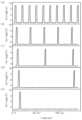
도 6의 (a), (b), (c), (d) 및 (e) 그래프를 참조하면, 일 실시예에 따른 게이트 드라이버(1)의 멀티 스테이지 240 Hz의 출력 신호 및 마스킹 신호(MSK)로 인해 조절된 60 Hz, 30 Hz 및 15 Hz의 출력 신호들을 확인할 수 있다. 이때 게이트 드라이버(1)의 다단 구동 시 출력 파형은 240 Hz 기준 절반에 해당하는 120의 인수(60 Hz, 40Hz ,30Hz ,20Hz, …)들과 그 이하에 해당하는 주파수를 갖는 출력 신호를 출력할 수 있음을 확인할 수 있다.Referring to the graphs of FIG. 6 (a), (b), (c), (d), and (e), the multi-stage 240 Hz output signal and masking signal (MSK) of the
도 7의 (a), (b), (c), (d), (e), (f) 및 (g) 그래프를 참조하면, 일 실시예에 따른 게이트 드라이버(1)의 멀티 스테이지 출력 신호 및 문턱 전압(△VTH)에 따른 출력 신호를 확인할 수 있다. 이때, 게이트 드라이버(1)의 증가형 모드(Enhancement Mode)의 구동뿐 아니라, 공핍형 모드(Depletion Mode)에서의 구동 시, 출력 신호의 파형은 박막 트랜지스터의 다양한 문턱 전압(-1.5 V ~ +3.0 V)에서도 안정적인 전압 값을 갖는 파형임을 확인할 수 있다.Referring to the graphs (a), (b), (c), (d), (e), (f), and (g) of FIG. 7, the multi-stage output signal of the
이상에서와 같이 첨부된 도면을 참조하여 개시된 실시예들을 설명하였다. 설명된 구성요소들의 성능에 대응하여 적어도 하나의 구성요소가 추가되거나 삭제될 수 있다. 또한, 구성요소들의 상호 위치는 시스템의 성능 또는 구조에 대응하여 변경될 수 있다는 것은 당해 기술 분야에서 통상의 지식을 가진 자에게 용이하게 이해될 것이다.As described above, the disclosed embodiments have been described with reference to the attached drawings. At least one component may be added or deleted in response to the performance of the described components. Additionally, it will be easily understood by those skilled in the art that the mutual positions of the components may be changed in response to the performance or structure of the system.
본 발명이 속하는 기술분야에서 통상의 지식을 가진 자는 본 발명의 기술적 사상이나 필수적인 특징을 변경하지 않고도, 개시된 실시예들과 다른 형태로 본 발명이 실시될 수 있음을 이해할 것이다. 개시된 실시예들은 예시적인 것이며, 한정적으로 해석되어서는 안 된다.A person skilled in the art to which the present invention pertains will understand that the present invention can be practiced in forms different from the disclosed embodiments without changing the technical idea or essential features of the present invention. The disclosed embodiments are illustrative and should not be construed as limiting.
1: 게이트 드라이버
100: 시프트 레지스터
101: 제1 노드
102: 제2 노드
103: 제3 노드
111: 제1 입력단
112: 제2 입력단
113: 제3 입력단
114: 제4 입력단
115: 제1 출력단
116: 제2 출력단
117: 제3 출력단
121: 제1 스위칭 소자
122: 제2 스위칭 소자
123: 제3 스위칭 소자
124: 제4 스위칭 소자
125: 제5 스위칭 소자
126: 제6 스위칭 소자
127: 제7 스위칭 소자
128: 제8 스위칭 소자
130: 커패시터
200: 마스킹 모듈
201: 제4 노드
211: 마스킹 신호 입력단
212: 제4 출력단
221: 제9 스위칭 소자
222: 제10 스위칭 소자
223: 제11 스위칭 소자
224: 제12 스위칭 소자
300: 제1 로우 전압 라인
400: 제2 로우 전압 라인1: Gate driver
100: shift register
101: first node
102: second node
103: third node
111: first input terminal
112: second input terminal
113: Third input terminal
114: fourth input terminal
115: first output stage
116: second output stage
117: Third output stage
121: first switching element
122: second switching element
123: third switching element
124: fourth switching element
125: fifth switching element
126: sixth switching element
127: 7th switching element
128: 8th switching element
130: capacitor
200: Masking module
201: fourth node
211: Masking signal input terminal
212: fourth output stage
221: Ninth switching element
222: 10th switching element
223: 11th switching element
224: 12th switching element
300: first low voltage line
400: second low voltage line
Claims (15)
Translated fromKorean상기 시프트 레지스터는:
위상이 상이한 복수개의 클록 신호들 중 두 개의 클록 신호들을 수신하고;
이전 순서의 시프트 레지스터로부터 상기 게이트 펄스의 로우 전압 값보다 낮은 로우 전압 값을 가지는 제1 전달 신호를 수신하고;
상기 이전 순서의 시프트 레지스터로부터 수신한 상기 제1 전달 신호를 기초로 상기 게이트 펄스를 생성하도록 구성되고;
한 주기 동안 순차적으로 하이 전압을 형성하도록 구성되는 제1 클록 신호, 제2 클록 신호 및 제3 클록 신호 중 두 개의 클록 신호들을 수신하고; 그리고
하이 전압 값은 상기 게이트 펄스의 하이 전압 값과 동일하고, 로우 전압 값은 제2 로우 전압으로 구성되는 펄스 신호인 제2 전달 신호를 생성하여 다음 순서의 시프트 레지스터로 전달하도록 구성되고,
상기 제2 로우 전압은, 상기 게이트 펄스의 로우 전압 값인 제1 로우 전압보다 작은 전압인, 게이트 드라이버에 있어서,
상기 시프트 레지스터는:
상기 프리 차지 신호를 수신하는 제1 입력단;
이전 순서의 시프트 레지스터로부터 상기 제1 전달 신호를 수신하는 제2 입력단;
상기 제1 클록 신호, 상기 제2 클록 신호 및 상기 제3 클록 신호 중 어느 한 클록 신호를 수신하는 제3 입력단; 및
상기 게이트 드라이버의 출력단에 연결되고 상기 게이트 펄스를 출력하는 제1 출력단을 포함하고,
상기 제2 입력단이 상기 제1 전달 신호를 수신하면, 상기 제1 입력단이 수신한 상기 프리 차지 신호가 상기 제3 입력단이 수신한 클록 신호로 인해 부트스트랩되어 생성되는 상기 게이트 펄스를 상기 제1 출력단으로 출력하도록 구성되고,
상기 다음 순서의 시프트 레지스터의 제1 입력단에 연결되어 상기 게이트 펄스를 출력하도록 구성되는 제2 출력단;
상기 다음 순서의 시프트 레지스터의 제2 입력단에 연결되어 상기 제2 전달 신호를 출력하도록 구성되는 제3 출력단; 및
상기 제1 입력단에 입력되지 않은 나머지 2개의 클록 신호들 중 어느 한 클록 신호를 수신하는 제4 입력단을 더 포함하고,
상기 제4 입력단이 펄스 신호를 수신하면, 상기 제1 출력단 및 상기 제2 출력단은 상기 제1 로우 전압을 출력하고, 상기 제3 출력단은 상기 제2 로우 전압을 출력하도록 구성되는, 게이트 드라이버.A plurality of shift registers configured to generate a gate pulse according to a received pre-charge signal and a first transfer signal and transmit the gate pulse to the next-order shift register as a pre-charge signal of the next-order shift register,
The shift register is:
Receiving two clock signals from among a plurality of clock signals having different phases;
receive a first transfer signal having a low voltage value lower than the low voltage value of the gate pulse from a shift register in the previous order;
configured to generate the gate pulse based on the first transfer signal received from the shift register of the previous order;
Receiving two clock signals of a first clock signal, a second clock signal, and a third clock signal configured to sequentially form a high voltage for one cycle; and
The high voltage value is the same as the high voltage value of the gate pulse, and the low voltage value is configured to generate a second transfer signal, which is a pulse signal consisting of a second low voltage, and transfer it to the next shift register,
In the gate driver, the second low voltage is a voltage smaller than the first low voltage, which is the low voltage value of the gate pulse,
The shift register is:
a first input terminal for receiving the precharge signal;
a second input terminal receiving the first transfer signal from a shift register in the previous order;
a third input terminal receiving any one of the first clock signal, the second clock signal, and the third clock signal; and
It includes a first output terminal connected to the output terminal of the gate driver and outputting the gate pulse,
When the second input terminal receives the first transmission signal, the gate pulse generated by bootstrapping the precharge signal received by the first input terminal due to the clock signal received by the third input terminal is transmitted to the first output terminal. It is configured to output as,
a second output terminal connected to a first input terminal of the next-order shift register and configured to output the gate pulse;
a third output terminal connected to a second input terminal of the next-order shift register and configured to output the second transmission signal; and
It further includes a fourth input terminal that receives one of the remaining two clock signals that are not input to the first input terminal,
When the fourth input terminal receives a pulse signal, the first output terminal and the second output terminal are configured to output the first low voltage, and the third output terminal is configured to output the second low voltage.
상기 시프트 레지스터는:
상기 이전 순서의 시프트 레지스터로부터 상기 제1 전달 신호를 수신하면, 수신된 상기 프리 차지 신호가 상기 두 개의 클록 신호들 중 어느 한 클록 신호로 인해 부트스트랩되어 상기 게이트 펄스를 생성하도록 구성되는, 게이트 드라이버.According to paragraph 1,
The shift register is:
A gate driver configured to, upon receiving the first transfer signal from the shift register in the previous order, bootstrap the received precharge signal due to one of the two clock signals to generate the gate pulse. .
상기 시프트 레지스터는:
상기 제1 출력단에 연결된 제1 노드와 상기 제3 입력단 사이에 마련되는 제1 스위칭 소자;
상기 제3 입력단과 상기 제3 출력단 사이에 마련되는 제2 스위칭 소자; 및
상기 제1 스위칭 소자 및 상기 제2 스위칭 소자에 전달되는 제어 신호가 인가되는 제2 노드와 상기 제1 노드 사이에 마련되는 커패시터를 더 포함하는, 게이트 드라이버.According to paragraph 1,
The shift register is:
a first switching element provided between a first node connected to the first output terminal and the third input terminal;
a second switching element provided between the third input terminal and the third output terminal; and
A gate driver further comprising a capacitor provided between the first node and a second node to which a control signal transmitted to the first switching element and the second switching element is applied.
상기 제1 스위칭 소자는,
상기 제2 노드로부터 수신한 제어 신호에 따라 상기 제1 노드와 상기 제3 입력단을 전기적으로 연결하도록 구성되고,
상기 제2 스위칭 소자는,
상기 제2 노드로부터 수신한 제어 신호에 따라 상기 제3 입력단과 상기 제3 출력단을 전기적으로 연결하도록 구성되는, 게이트 드라이버.In clause 7,
The first switching element is,
configured to electrically connect the first node and the third input terminal according to a control signal received from the second node,
The second switching element is,
A gate driver configured to electrically connect the third input terminal and the third output terminal according to a control signal received from the second node.
상기 시프트 레지스터는:
상기 제1 입력단과 상기 제2 노드 사이에 마련되는 제5 스위칭 소자를 더 포함하고,
상기 제5 스위칭 소자는,
상기 제2 입력단으로부터 수신한 상기 제1 전달 신호에 따라 상기 제1 입력단과 상기 제2 노드를 전기적으로 연결하도록 구성되는, 게이트 드라이버.According to clause 8,
The shift register is:
Further comprising a fifth switching element provided between the first input terminal and the second node,
The fifth switching element is,
A gate driver configured to electrically connect the first input terminal and the second node according to the first transmission signal received from the second input terminal.
상기 시프트 레지스터는:
상기 제1 로우 전압이 인가되는 제1 로우 전압 라인;
상기 제2 로우 전압이 인가되는 제2 로우 전압 라인;
상기 제1 노드와 상기 제1 로우 전압 라인 사이에 마련되는 제3 스위칭 소자; 및
상기 제3 출력단과 상기 제2 로우 전압 라인 사이에 마련되는 제4 스위칭 소자를 더 포함하는, 게이트 드라이버.In clause 7,
The shift register is:
a first low voltage line to which the first low voltage is applied;
a second low voltage line to which the second low voltage is applied;
a third switching element provided between the first node and the first low voltage line; and
The gate driver further includes a fourth switching element provided between the third output terminal and the second low voltage line.
상기 시프트 레지스터는,
상기 제3 스위칭 소자 및 상기 제4 스위칭 소자에 전달되는 제어 신호가 인가되는 제3 노드를 더 포함하고,
상기 제3 스위칭 소자는,
상기 제3 노드로부터 수신한 제어 신호에 따라 상기 제1 노드와 상기 제1 로우 전압 라인을 전기적으로 연결하도록 구성되고,
상기 제4 스위칭 소자는,
상기 제3 노드로부터 수신한 제어 신호에 따라 상기 제3 출력단과 상기 제2 로우 전압 라인을 전기적으로 연결하도록 구성되는, 게이트 드라이버.According to clause 10,
The shift register is,
Further comprising a third node to which a control signal transmitted to the third switching element and the fourth switching element is applied,
The third switching element is,
configured to electrically connect the first node and the first low voltage line according to a control signal received from the third node,
The fourth switching element is,
A gate driver configured to electrically connect the third output terminal and the second low voltage line according to a control signal received from the third node.
상기 시프트 레지스터는:
상기 제3 노드와 상기 제2 로우 전압 라인 사이에 마련되는 제6 스위칭 소자;
상기 제3 노드와 상기 제4 입력단 사이에 마련되는 제7 스위칭 소자; 및
상기 제2 노드와 상기 제2 로우 전압 라인 사이에 마련되는 제8 스위칭 소자를 더 포함하고,
상기 제6 스위칭 소자는,
상기 제1 입력단으로부터 수신한 상기 프리 차지 신호에 따라 상기 제3 노드와 상기 제2 로우 전압 라인을 전기적으로 연결하도록 구성되고,
상기 제7 스위칭 소자는,
상기 제4 입력단으로부터 수신한 클록 신호에 따라 상기 제3 노드와 상기 제4 입력단을 전기적으로 연결하도록 구성되고,
상기 제8 스위칭 소자는,
상기 제4 입력단으로부터 수신한 클록 신호에 따라 상기 제2 노드와 상기 제2 로우 전압 라인을 전기적으로 연결하도록 구성되는, 게이트 드라이버.According to clause 11,
The shift register is:
a sixth switching element provided between the third node and the second low voltage line;
a seventh switching element provided between the third node and the fourth input terminal; and
Further comprising an eighth switching element provided between the second node and the second low voltage line,
The sixth switching element is,
Configured to electrically connect the third node and the second low voltage line according to the precharge signal received from the first input terminal,
The seventh switching element is,
configured to electrically connect the third node and the fourth input terminal according to a clock signal received from the fourth input terminal,
The eighth switching element is,
A gate driver configured to electrically connect the second node and the second low voltage line according to a clock signal received from the fourth input terminal.
상기 시프트 레지스터의 제1 출력단에 연결되어 상기 제1 출력단으로부터 상기 게이트 펄스를 전달받고, 게이트 라인에 연결된 제4 출력단으로 마스킹 모듈 출력 신호를 출력하도록 구성되는 마스킹 모듈을 더 포함하고,
복수의 상기 시프트 레지스터들은,
각각 하나의 마스킹 모듈에 연결되고,
상기 마스킹 모듈은:
상기 시프트 레지스터에 대응되는 게이트 라인에 대한 신호의 전달을 차단하고자 할 경우 생성되는 마스킹 신호를 수신하는 마스킹 신호 입력단을 포함하고,
상기 마스킹 신호의 수신 여부에 따라 상기 게이트 펄스를 상기 마스킹 모듈 출력 신호로서 상기 게이트 라인에 출력하도록 구성되는, 게이트 드라이버.According to paragraph 1,
It further includes a masking module connected to a first output terminal of the shift register, receiving the gate pulse from the first output terminal, and outputting a masking module output signal to a fourth output terminal connected to the gate line,
The plurality of shift registers are:
Each is connected to one masking module,
The masking module:
It includes a masking signal input terminal that receives a masking signal generated when it is desired to block transmission of a signal to the gate line corresponding to the shift register,
A gate driver configured to output the gate pulse to the gate line as the masking module output signal depending on whether the masking signal is received.
상기 제1 로우 전압이 인가되는 제1 로우 전압 라인을 더 포함하고,
상기 마스킹 모듈은:
상기 제1 출력단과 제4 노드 사이에 마련되는 제9 스위칭 소자;
상기 제1 출력단과 상기 제4 출력단 사이에 마련되는 제10 스위칭 소자;
상기 제4 노드와 상기 제1 로우 전압 라인 사이에 마련되는 제11 스위칭 소자; 및
상기 제4 출력단과 상기 제1 로우 전압 라인 사이에 마련되는 제12 스위칭 소자를 더 포함하는, 게이트 드라이버.According to clause 13,
Further comprising a first low voltage line to which the first low voltage is applied,
The masking module:
A ninth switching element provided between the first output terminal and the fourth node;
a tenth switching element provided between the first output terminal and the fourth output terminal;
an 11th switching element provided between the fourth node and the first low voltage line; and
The gate driver further includes a twelfth switching element provided between the fourth output terminal and the first low voltage line.
상기 제9 스위칭 소자는,
상기 제1 출력단으로부터 수신한 상기 게이트 펄스에 따라 상기 제1 출력단과 상기 제4 노드를 전기적으로 연결하도록 구성되고,
상기 제10 스위칭 소자는,
상기 제4 노드로부터 수신한 제어 신호에 따라 상기 제1 출력단과 상기 제4 출력단을 전기적으로 연결하도록 구성되고,
상기 제11 스위칭 소자는,
상기 마스킹 신호 입력단으로부터 수신한 상기 마스킹 신호에 따라 상기 제4 노드와 상기 제1 로우 전압 라인을 전기적으로 연결하도록 구성되고,
상기 제12 스위칭 소자는,
상기 마스킹 신호 입력단으로부터 수신한 상기 마스킹 신호에 따라 상기 제4 출력단과 상기 제1 로우 전압 라인을 전기적으로 연결하도록 구성되는, 게이트 드라이버.According to clause 14,
The ninth switching element is,
configured to electrically connect the first output terminal and the fourth node according to the gate pulse received from the first output terminal,
The tenth switching element is,
configured to electrically connect the first output terminal and the fourth output terminal according to a control signal received from the fourth node,
The eleventh switching element is,
configured to electrically connect the fourth node and the first low voltage line according to the masking signal received from the masking signal input terminal,
The twelfth switching element is:
A gate driver configured to electrically connect the fourth output terminal and the first low voltage line according to the masking signal received from the masking signal input terminal.
Priority Applications (1)
| Application Number | Priority Date | Filing Date | Title |
|---|---|---|---|
| KR1020220065647AKR102625976B1 (en) | 2022-05-27 | 2022-05-27 | Gate driver capable of stably operating at multiple frequencies |
Applications Claiming Priority (1)
| Application Number | Priority Date | Filing Date | Title |
|---|---|---|---|
| KR1020220065647AKR102625976B1 (en) | 2022-05-27 | 2022-05-27 | Gate driver capable of stably operating at multiple frequencies |
Publications (2)
| Publication Number | Publication Date |
|---|---|
| KR20230165628A KR20230165628A (en) | 2023-12-05 |
| KR102625976B1true KR102625976B1 (en) | 2024-01-16 |
Family
ID=89157493
Family Applications (1)
| Application Number | Title | Priority Date | Filing Date |
|---|---|---|---|
| KR1020220065647AActiveKR102625976B1 (en) | 2022-05-27 | 2022-05-27 | Gate driver capable of stably operating at multiple frequencies |
Country Status (1)
| Country | Link |
|---|---|
| KR (1) | KR102625976B1 (en) |
Family Cites Families (4)
| Publication number | Priority date | Publication date | Assignee | Title |
|---|---|---|---|---|
| CN102024410B (en)* | 2009-09-16 | 2014-10-22 | 株式会社半导体能源研究所 | Semiconductor devices and electronic equipment |
| KR101983976B1 (en)* | 2011-05-13 | 2019-05-30 | 가부시키가이샤 한도오따이 에네루기 켄큐쇼 | Semiconductor device |
| KR102020932B1 (en)* | 2013-05-09 | 2019-09-11 | 엘지디스플레이 주식회사 | Scan Driver and Display Device Using the same |
| KR102174833B1 (en)* | 2019-02-01 | 2020-11-05 | 성균관대학교산학협력단 | Gate Driving Circuit and Display Device having the Same |
- 2022
- 2022-05-27KRKR1020220065647Apatent/KR102625976B1/enactiveActive
Also Published As
| Publication number | Publication date |
|---|---|
| KR20230165628A (en) | 2023-12-05 |
Similar Documents
| Publication | Publication Date | Title |
|---|---|---|
| CN111243650B (en) | Shifting register, driving method thereof and grid driving circuit | |
| US11893922B2 (en) | Shift register, gate drive circuit and display panel | |
| US11127478B2 (en) | Shift register unit and driving method thereof, gate driving circuit, and display device | |
| US7233308B2 (en) | Shift register | |
| CN102959614B (en) | Scan signal line drive circuit and the display device possessing it | |
| CN203773916U (en) | Shift register unit, shift register and display device | |
| EP3944223A1 (en) | Shift register unit, driving circuit, display apparatus, and driving method | |
| US20200020291A1 (en) | Shift Register Circuit, Method for Driving the Same, Gate Drive Circuit, and Display Panel | |
| CN113299223B (en) | Display panel and display device | |
| US10770018B2 (en) | Scanning signal line drive circuit, display device including the same, and scanning signal line driving method | |
| KR20130139328A (en) | Shift register unit and driving method thereof, shift register and display apparatus | |
| JP2006189762A (en) | Shift resist for flat panel display | |
| US10923064B2 (en) | Scanning signal line drive circuit and display device equipped with same | |
| CN110782940B (en) | Shift register unit, gate drive circuit, array substrate and display device | |
| WO2016161727A1 (en) | Shift register unit, driving method therefor, array substrate gate electrode driver device, and display panel | |
| CN104809973A (en) | Shifting register adaptable to negative threshold voltage and units thereof | |
| US7286627B2 (en) | Shift register circuit with high stability | |
| CN107210067B (en) | Shift register circuit and display device having the same | |
| KR20190139481A (en) | Gate driving circuit and display device comprising the same | |
| US20220351793A1 (en) | Shift register circuit, active matrix substrate, and display apparatus | |
| WO2021190038A1 (en) | Shift register and method for driving same, and gate drive circuit | |
| EP3742424B1 (en) | Shift register, driving method therefor and gate drive circuit | |
| CN110599978A (en) | Shift register, grid drive circuit and display device | |
| KR20190069182A (en) | Shift resister and display device having the same | |
| US20210209988A1 (en) | Shift register unit and method for driving the same, gate driving circuit and method for driving the same, and display apparatus |
Legal Events
| Date | Code | Title | Description |
|---|---|---|---|
| PA0109 | Patent application | Patent event code:PA01091R01D Comment text:Patent Application Patent event date:20220527 | |
| PA0201 | Request for examination | ||
| PE0902 | Notice of grounds for rejection | Comment text:Notification of reason for refusal Patent event date:20230914 Patent event code:PE09021S01D | |
| PG1501 | Laying open of application | ||
| E701 | Decision to grant or registration of patent right | ||
| PE0701 | Decision of registration | Patent event code:PE07011S01D Comment text:Decision to Grant Registration Patent event date:20240111 | |
| GRNT | Written decision to grant | ||
| PR0701 | Registration of establishment | Comment text:Registration of Establishment Patent event date:20240112 Patent event code:PR07011E01D | |
| PR1002 | Payment of registration fee | Payment date:20240112 End annual number:3 Start annual number:1 | |
| PG1601 | Publication of registration |