KR102622224B1 - Current transformer - Google Patents
Current transformerDownload PDFInfo
- Publication number
- KR102622224B1 KR102622224B1KR1020160100171AKR20160100171AKR102622224B1KR 102622224 B1KR102622224 B1KR 102622224B1KR 1020160100171 AKR1020160100171 AKR 1020160100171AKR 20160100171 AKR20160100171 AKR 20160100171AKR 102622224 B1KR102622224 B1KR 102622224B1
- Authority
- KR
- South Korea
- Prior art keywords
- current transformer
- housing
- coupled
- fastening
- hinge
- Prior art date
- Legal status (The legal status is an assumption and is not a legal conclusion. Google has not performed a legal analysis and makes no representation as to the accuracy of the status listed.)
- Active
Links
- 230000008878couplingEffects0.000claimsdescription22
- 238000010168coupling processMethods0.000claimsdescription22
- 238000005859coupling reactionMethods0.000claimsdescription22
- 238000003780insertionMethods0.000claimsdescription9
- 230000037431insertionEffects0.000claimsdescription9
- 230000000694effectsEffects0.000description9
- 230000006698inductionEffects0.000description9
- 238000000926separation methodMethods0.000description6
- 238000010586diagramMethods0.000description5
- 238000009434installationMethods0.000description4
- 238000012423maintenanceMethods0.000description3
- 238000005192partitionMethods0.000description3
- 230000006866deteriorationEffects0.000description2
- 230000004308accommodationEffects0.000description1
- 230000005540biological transmissionEffects0.000description1
- 230000007423decreaseEffects0.000description1
- 230000007547defectEffects0.000description1
- 230000001939inductive effectEffects0.000description1
- 210000004185liverAnatomy0.000description1
- 238000000034methodMethods0.000description1
- 238000012986modificationMethods0.000description1
- 230000004048modificationEffects0.000description1
- 230000035515penetrationEffects0.000description1
Images


Classifications
- H—ELECTRICITY
- H01—ELECTRIC ELEMENTS
- H01F—MAGNETS; INDUCTANCES; TRANSFORMERS; SELECTION OF MATERIALS FOR THEIR MAGNETIC PROPERTIES
- H01F38/00—Adaptations of transformers or inductances for specific applications or functions
- H01F38/20—Instruments transformers
- H01F38/22—Instruments transformers for single phase AC
- H01F38/28—Current transformers
- H01F38/30—Constructions
- H—ELECTRICITY
- H01—ELECTRIC ELEMENTS
- H01F—MAGNETS; INDUCTANCES; TRANSFORMERS; SELECTION OF MATERIALS FOR THEIR MAGNETIC PROPERTIES
- H01F27/00—Details of transformers or inductances, in general
- H01F27/24—Magnetic cores
- H—ELECTRICITY
- H01—ELECTRIC ELEMENTS
- H01F—MAGNETS; INDUCTANCES; TRANSFORMERS; SELECTION OF MATERIALS FOR THEIR MAGNETIC PROPERTIES
- H01F38/00—Adaptations of transformers or inductances for specific applications or functions
- H01F38/20—Instruments transformers
- H01F38/22—Instruments transformers for single phase AC
- H01F38/28—Current transformers
Landscapes
- Engineering & Computer Science (AREA)
- Power Engineering (AREA)
- Transformers For Measuring Instruments (AREA)
Abstract
Translated fromKoreanDescription
Translated fromKorean본 발명은 변류기에 관한 것으로, 더욱 상세하게는 자기유도 현상을 이용해 선로로부터 전력을 생산하거나, 전류를 감지하는 자기유도 전원 공급 장치에 실장되는 변류기에 관한 것이다.The present invention relates to a current transformer, and more specifically, to a current transformer mounted on a magnetic induction power supply device that generates power from a line using a magnetic induction phenomenon or detects current.
최근 자기유도 현상을 이용한 전원 공급 방식에 대한 관심이 증가함에 따라 다양한 형태의 자기유도 전원 공급 장치가 개발되고 있다.Recently, as interest in power supply methods using magnetic induction phenomenon increases, various types of magnetic induction power supply devices are being developed.
자기유도 방식의 전원 공급 장치는 송전선로, 배전 선로 등과 같이 대용량 전류가 흐르는 전력선에 설치되는 변류기를 포함한다. 자기유도 방식 전원 공급 장치는 변류기에서 자기유도 현상을 통해 취득한 전력을 직류로 변환하여 부하로 공급한다.A magnetic induction type power supply device includes a current transformer installed on a power line through which a large amount of current flows, such as a transmission line or distribution line. A magnetic induction power supply device converts the power obtained through the magnetic induction phenomenon from a current transformer into direct current and supplies it to the load.
한편, 변류기는 자유 유도 방식의 전원 공급 장치로 사용될 수 있다. 즉, 변류기는 선로에 설치되어 선로에서 발생하는 자기유도 현상을 이용하여 전력을 취득하거나 전류를 센싱한다.Meanwhile, the current transformer can be used as a free inductive power supply. In other words, the current transformer is installed on the line and acquires power or senses current using the magnetic induction phenomenon occurring in the line.
종래의 변류기는 상부 구조물과 하부 구조물이 분리된 상태로 제작되며, 상부 구조물과 하부 구조물의 양측에 형성된 체결 부재를 체결하여 선로에 설치된다.Conventional current transformers are manufactured with the upper and lower structures separated, and are installed on the track by fastening fastening members formed on both sides of the upper and lower structures.
이때, 종래의 변류기는 상부 구조물 및 하부 구조물의 양측을 체결해야 하기 때문에 다수의 작업자가 있어야 하는 문제점이 있다. 즉, 상부 구조물과 하부 구조물을 지지하는 작업자와 체결하는 작업자가 동시에 설치 작업을 수행해야 하기 때문에 설치 및 유지 보수에 많은 비용이 소비되는 문제점이 있다.At this time, the conventional current transformer has a problem in that it requires a large number of workers because both sides of the upper structure and the lower structure must be fastened. In other words, there is a problem in that a lot of cost is spent on installation and maintenance because workers supporting the upper structure and lower structure and workers fastening them must perform installation work at the same time.
또한, 종래의 변류기는 상부 구조물과 하부 구조물의 체결을 위해 볼트와 너트로 구성된 체결 부재를 이용하기 때문에, 설치 및 유지 보수 작업시 상부 구조물 및 하부 구조물에 수용된 코어들 간의 정렬 및 결합이 정확하게 이루어지지 않아 변류기의 성능이 저하되는 문제점이 있다.In addition, because the conventional current transformer uses fastening members composed of bolts and nuts to fasten the upper structure and the lower structure, accurate alignment and connection between the cores accommodated in the upper and lower structures are difficult to achieve during installation and maintenance work. There is a problem in that the performance of the current transformer deteriorates.
본 발명은 상기한 종래의 문제점을 해결하기 위해 제안된 것으로, 선로가 수용되는 홈이 형성된 상부 하우징의 일측과 본체 하우징의 일측을 힌지 부재로 연결하여 설치 및 유지 보수가 용이하고, 변류기의 성능을 일정하게 유지하도록 한 변류기를 제공하는 것을 목적으로 한다.The present invention was proposed to solve the above-described conventional problems. One side of the upper housing where the groove for receiving the line is formed and one side of the main housing are connected by a hinge member to facilitate installation and maintenance, and to improve the performance of the current transformer. The purpose is to provide a current transformer that can be kept constant.
상기한 목적을 달성하기 위하여 본 발명의 실시예에 따른 변류기는 마그네틱 코어가 수용되는 본체 하우징 및 다른 마그네틱 코어가 수용되고, 선로가 수용되는 선로 수용 홈이 형성되는 상부 하우징을 포함하고, 상부 하우징 및 본체 하우징의 일측은 힌지 부재로 결합된다.In order to achieve the above object, a current transformer according to an embodiment of the present invention includes a main housing in which a magnetic core is accommodated, an upper housing in which another magnetic core is accommodated, and a line receiving groove in which a line is accommodated is formed, the upper housing and One side of the main housing is coupled with a hinge member.
본체 하우징은 일측에 하부 힌지 수단을 구비하고, 타측에 하부 체결 수단을 구비하고, 상부 하우징은 일측에 하부 힌지 수단과 결합되는 상부 힌지 수단을 구비하고, 타측에 하부 체결 수단과 결합되는 상부 체결 수단을 구비할 수 있으며, 여기서 하부 힌지 수단과 상부 힌지 수단은 힌지 핀이 삽입되는 힌지 핀 삽입 홀이 형성되어 힌지 핀을 통해 회동 가능한 상태로 결합되고, 하부 체결 수단과 상부 체결 수단은 체결 핀이 삽입되는 체결 핀 삽입 홀이 형성되어 체결 핀을 통해 결합될 수 있다.The main housing has a lower hinge means on one side and a lower fastening means on the other side, and the upper housing has an upper hinge means coupled with the lower hinge means on one side and an upper fastening means coupled with the lower fastening means on the other side. It may be provided, wherein the lower hinge means and the upper hinge means are coupled in a rotatable state through the hinge pin by forming a hinge pin insertion hole into which the hinge pin is inserted, and the lower fastening means and the upper fastening means have a fastening pin inserted. A fastening pin insertion hole is formed so that they can be coupled through the fastening pin.
본체 하우징에 수용되는 마그네틱 코어는 단부의 일부가 본체 하우징의 상부로 노출될 수 있다.A portion of an end of the magnetic core accommodated in the main housing may be exposed to the upper part of the main housing.
선로 수용 홈은 반원통형 및 육면체가 결합된 형상일 수 있다.The track receiving groove may be a combination of a semi-cylindrical shape and a hexahedron shape.
본 발명의 실시예에 따른 변류기는 본체 하우징의 상면에 결합되어, 본체 하우징의 상면의 적어도 일부를 덮는 보빈 커버를 더 포함할 수 있다. 이때, 보빈 커버는 마그네틱 코어의 단부가 관통하는 코어 관통 홀이 형성될 수 있다.The current transformer according to an embodiment of the present invention may further include a bobbin cover that is coupled to the upper surface of the main housing and covers at least a portion of the upper surface of the main housing. At this time, the bobbin cover may have a core penetration hole through which the end of the magnetic core penetrates.
본 발명의 실시예에 따른 변류기는 라운드 형상의 굴곡을 갖는 판상으로 형성되어 상부 하우징과 다른 마그네틱 코어 사이에 개재되고, 다른 마그네틱 코어에 하부 방향으로 장력을 가하는 장력 부재를 더 포함할 수 있다. 이때, 상부 하우징은 장력 부재 결합 홈이 형성되고, 장력 부재의 양단은 장력 부재 결합 홈에 결합될 수 있다.The current transformer according to an embodiment of the present invention is formed in a plate shape with a round bend and is interposed between the upper housing and another magnetic core, and may further include a tension member that applies tension to the other magnetic core in a downward direction. At this time, the upper housing is formed with a tension member coupling groove, and both ends of the tension member may be coupled to the tension member coupling groove.
본 발명의 실시예에 따른 변류기는 선로 수용 홈에 대응되는 형상으로 형성되어 선로 수용 홈에 결합되고, 다른 마그네틱 코어의 하부를 지지하는 지지 수단을 더 포함할 수 있다. 이때, 상부 하우징은 지지 수단 결함 홈이 형성되고, 지지 수단은 지지 수단 결합 홈에 결합되는 지지 수단 고정용 돌기가 형성되고, 지지 수단은 측부에서 상부로 연장되는 가이드 돌기가 형성될 수 있다.The current transformer according to an embodiment of the present invention is formed in a shape corresponding to the line receiving groove and is coupled to the line receiving groove, and may further include a support means for supporting the lower part of another magnetic core. At this time, the upper housing may be formed with a defect groove for the support means, the support means may be formed with a protrusion for fixing the support means coupled to the support means coupling groove, and the support means may be formed with a guide protrusion extending from the side to the top.
본 발명에 의하면, 변류기는 본체 하우징과 상부 하우징을 결합시 힌지 수단을 통해 일측이 회동 가능한 상태로 결합되고 타측이 체결 수단에 의해 체결됨으로써, 한 명의 작업자가 변류기를 선로에 설치하기 용이한 효과가 있다. 즉, 변류기는 일측이 힌지 수단으로 결합되어 있는 상태에서 타측의 체결 부재를 이용하여 선로에 설치할 수 있기 때문에 양측을 모두 체결해야 하는 종래의 변류기에 비해 설치가 용이한 효과가 있다.According to the present invention, when the main housing and the upper housing of the current transformer are combined, one side is rotatably coupled through a hinge means and the other side is fastened by a fastening means, which makes it easy for one worker to install the current transformer on the line. there is. In other words, since the current transformer can be installed on the line using a fastening member on the other side while one side is coupled by a hinge means, it has the effect of being easier to install compared to a conventional current transformer in which both sides must be fastened.
또한, 변류기는 힌지 수단 및 체결 수단을 이용해 선로에 설치됨으로써, 상부 코어 및 하부 코어의 단면들이 일정한 압력으로 결합할 수 있는 효과가 있다.In addition, the current transformer is installed on the line using a hinge means and a fastening means, which has the effect of combining the cross sections of the upper core and the lower core with a constant pressure.
또한, 변류기는 일측이 힌지 수단으로 결합된 상태에서 타측의 체결 수단을 통해 선로에 설치되기 때문에 상부 코어 및 하부 코어의 양쪽 단면에 동일한 힘을 가하여 변류기 성능의 저하를 방지할 수 있다.In addition, since the current transformer is installed on the line through a fastening means on the other side while one side is coupled with a hinge means, the same force can be applied to both end surfaces of the upper core and the lower core to prevent deterioration of the current transformer performance.
또한, 변류기는 하부 코어의 일단이 삽입되는 관통 홀이 형성된 보빈 커버를 본체 하우징에 결합함으로써, 하부 코어의 위치를 정확하게 유지하고, 진동에 의한 하부 코어의 이탈(이동)을 방지할 수 있는 효과가 있다.In addition, the current transformer has the effect of accurately maintaining the position of the lower core and preventing separation (movement) of the lower core due to vibration by coupling the bobbin cover with a through hole into which one end of the lower core is inserted to the main body housing. there is.
또한, 변류기는 하부 코어의 일단이 삽입되는 관통 홀이 형성된 보빈 커버를 본체 하우징에 결합하여 하부 코어의 이탈(이동)을 방지함으로써, 상부 코어와 하부 코어가 정확한 위치에서 결합되어 변류기의 성능을 최적 상태로 유지할 수 있는 효과가 있다.In addition, the current transformer prevents separation (movement) of the lower core by attaching a bobbin cover with a through hole into which one end of the lower core is inserted to the main housing, so that the upper core and lower core are combined at the correct position to optimize the performance of the current transformer. It has the effect of maintaining the condition.
또한, 변류기는 힌지 수단 및 체결 수단을 이용한 선로에 설치되고, 보빈 커버를 통해 하부 코어의 이탈(이동)을 방지함으로써, 작업자가 하부 코어 및 상부 코어의 정렬 상태 및 가해지는 힘을 고려하지 않고 간단한 조작으로 설치할 수 있어 변류기의 성능 구현 및 유지 보수가 용이한 효과가 있다.In addition, the current transformer is installed on the line using a hinge means and a fastening means, and prevents the separation (movement) of the lower core through the bobbin cover, so that the operator can simply operate it without considering the alignment status and applied force of the lower core and upper core. It can be installed by operation, which has the effect of making it easy to realize the performance of the current transformer and to maintain it.
도 1 내지 도 3은 본 발명의 실시예에 따른 변류기를 설명하기 위한 도면.
도 4는 도 3의 본체 하우징을 설명하기 위한 도면.
도 5는 도 3의 보빈 커버를 설명하기 위한 도면.
도 6 내지 도 8은 도 3의 상부 하우징을 설명하기 위한 도면.
도 9는 도 3의 장력 부재를 설명하기 위한 도면.
도 10은 도 3의 지지 수단을 설명하기 위한 도면.1 to 3 are diagrams for explaining a current transformer according to an embodiment of the present invention.
Figure 4 is a diagram for explaining the main housing of Figure 3.
Figure 5 is a diagram for explaining the bobbin cover of Figure 3.
6 to 8 are views for explaining the upper housing of FIG. 3.
FIG. 9 is a diagram for explaining the tension member of FIG. 3.
Figure 10 is a diagram for explaining the support means of Figure 3.
이하, 본 발명이 속하는 기술분야에서 통상의 지식을 가진 자가 본 발명의 기술적 사상을 용이하게 실시할 수 있을 정도로 상세히 설명하기 위하여, 본 발명의 가장 바람직한 실시예를 첨부 도면을 참조하여 설명하기로 한다. 우선 각 도면의 구성요소들에 참조부호를 부가함에 있어서, 동일한 구성요소들에 대해서는 비록 다른 도면상에 표시되더라도 가능한 한 동일한 부호를 가지도록 하고 있음에 유의해야 한다. 또한, 본 발명을 설명함에 있어, 관련된 공지 구성 또는 기능에 대한 구체적인 설명이 본 발명의 요지를 흐릴 수 있다고 판단되는 경우에는 그 상세한 설명은 생략한다.Hereinafter, in order to explain in detail enough to enable those skilled in the art of the present invention to easily implement the technical idea of the present invention, the most preferred embodiments of the present invention will be described with reference to the accompanying drawings. . First, when adding reference numerals to components in each drawing, it should be noted that identical components are given the same reference numerals as much as possible even if they are shown in different drawings. Additionally, in describing the present invention, if it is determined that a detailed description of a related known configuration or function may obscure the gist of the present invention, the detailed description will be omitted.
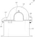
도 1 내지 도 3을 참조하면, 변류기(100)는 본체 하우징(110), 보빈 커버(120), 상부 하우징(130), 장력 부재(140), 지지 수단(150)을 포함하여 구성된다. 이때, 변류기(100)는 전력선에서 발생하는 자기유도 현상을 이용하여 전원을 취득하거나, 전류를 센싱하기 위한 변류기(100)이다.1 to 3, the
본체 하우징(110)은 내부에 마그네틱 코어(이하, 하부 코어(210))가 수용된다. 본체 하우징(110)은 하부 코어(210)가 수용된 상태에서 상부의 일부 또는 전체를 덮는 보빈 커버(120)가 상부에 결합된다. 이때, 보빈 커버(120)에는 관통 홀이 형성되며, 관통 홀을 통해 하부 코어(210)의 단부가 외부(즉, 본체 하우징(110)이 상부 방향)로 노출된다.The
상부 하우징(130)은 내부에 장력 부재(140)가 결합된 상태에서 다른 마그네틱 코어(이하, 상부 코어(220))가 수용되고, 하부에 지지 수단(150)이 결합된다. 상부 하우징(130)은 상부가 반원통형으로 형성되며, 선로가 삽입되는 홈이 형성된다. 이때, 본체 하우징(110) 및 상부 하우징(130)은 힌지 부재를 통해 일측이 회동 가능한 상태로 결합되고, 타측이 체결 부재를 통해 결합된다.The
변류기(100)의 각 구성들을 첨부된 도면을 참조하여 설명하면 아래와 같다.Each component of the
도 4를 참조하면, 본체 하우징(110)은 하부 코어(210)가 내장되는 하부 수용 공간(111)이 내부에 형성된다. 즉, 본체 하우징(110)은 하부 외벽(112)과 하부 외벽(112)에 직교하는 4개의 측부 외벽(113)들로 구성되어, 하부 코어(210)가 내장되는 하부 수용 공간(111)을 형성한다. 이때, 본체 하우징(110)의 외벽은 하부 코어(210)보다 낮은 높이로 형성되어, 하부 수용 공간(111)에 수용된 하부 코어(210)의 일단 일부가 외부(즉, 상부)로 노출되도록 할 수도 있다.Referring to FIG. 4, the
한편, 본체 하우징(110)은 하부 수용 공간(111)을 복수의 공간으로 구분하기 위해 복수의 격벽(114)들이 형성될 수도 있다. 즉, 하부 수용 공간(111)의 내부에는 하부 수용 공간(111)을 하부 코어 수용 공간, 회로기판 수용 공간 등으로 구분하는 복수의 격벽(114)들이 형성될 수도 있다. 여기서, 복수의 격벽(114)들은 본체 하우징(110)보다 낮은 높이를 갖도록 형성되며, 공간 구분과 함께 하부 코어(210)에 삽입 실장되는 보빈(230)을 지지하는 역할을 수행한다.Meanwhile, the
본체 하우징(110)은 일측에 상부 하우징(130)과의 결합을 위한 하부 힌지 수단(115)을 구비한다. 하부 힌지 수단(115)은 본체 하우징(110)의 일측 상부에서 외부 방향으로 연장되어 형성된다. 하부 힌지 수단(115)은 상부 하우징(130)에 형성되는 상부 힌지 수단(135)에 대응되는 구조로 형성되며, 상부 힌지 수단(135)과 결합된 후 힌지 핀(240)이 삽입되는 힌지 핀 삽입 홀(115a)이 형성된다.The
본체 하우징(110)은 타측에 상부 하우징(130)과의 결합을 위한 하부 체결 수단(116)을 구비한다. 즉, 본체 하우징(110)은 하부 힌지 수단(115)이 형성된 일측에 대향되는 타측의 상부에 하부 체결 수단(116)이 형성된다.The
이때, 하부 체결 수단(116)은 본체 하우징(110)의 타측 상부에서 외부 방향으로 연장되어 형성된다. 하부 체결 수단(116)은 상부 하우징(130)에 형성되는 상부 체결 수단(137)에 대응되는 구조로 형성되며, 본체 하우징(110)과 상부 하우징(130)이 결합된 후 체결 핀(250; 예를 들면, 볼트 등)이 삽입되는 체결 핀 삽입 홀(116a)이 형성된다. 여기서, 체결 핀 삽입 홀(116a)의 내벽에는 체결 핀(250)에 대응되는 나사산이 형성될 수도 있다.At this time, the lower fastening means 116 is formed to extend outward from the upper part of the other side of the
본체 하우징(110)은 변류기(100)의 고정을 위한 고정용 홈(117a)이 형성된 복수의 고정 돌기(117)들이 형성될 수도 있다. 즉, 본체 하우징(110)은 측면 하부에서 외부 방향으로 연장된 복수의 고정 돌기(117)들이 형성된다. 이때, 복수의 고정 돌기(117) 각각에는 고정용 홈(117a)이 형성된다. 여기서, 고정용 홈(117a)의 내벽에는 변류기(100)의 고정을 위한 볼트에 대응되는 나사산이 형성될 수도 있다.The
본체 하우징(110)은 보빈 커버(120)와의 결합을 위한 복수의 본체 체결 돌기(118)들이 형성될 수도 있다. 즉, 본체 하우징(110)은 상부 힌지 부재가 형성된 일측면에 인접한 측면들에 복수의 본체 체결 돌기(118)들이 형성될 수 있다. 이때, 본체 체결 돌기(118)에는 보빈 커버(120)의 체결을 위한 본체 체결 홈(118a)이 형성되고, 본체 체결 홈(118a)의 내벽에는 보빈 커버(120)의 체결을 위한 볼트에 대응되는 나사산이 형성될 수도 있다.The
도 5를 참조하면, 보빈 커버(120)는 본체 하우징(110)의 상면에 체결된다. 즉, 보빈 커버(120)는 본체 하우징(110)의 상면 일부 또는 전체를 덮는 면적을 갖도록 형성된다. 이때, 보빈 커버(120)는 본체 하우징(110)에 수용되는 하부 코어(210)에 삽입 실장되는 보빈(230)의 상부에 배치된다.Referring to FIG. 5, the
보빈 커버(120)는 하부 코어(210)의 일단이 관통하는 코어 관통 홀(121)이 형성된다. 즉, 하부 코어(210)는 상부 하우징(130)에 수용되는 상부 코어(220)와 양단이 결합되어야 하기 때문에 양단부의 일부가 본체 하우징(110)의 외부로 노출되어야 한다. 이에, 보빈 커버(120)는 하부 코어(210)의 일단을 외부로 노출시키는 코어 관통 홀(121)이 형성된다. 여기서, 보빈 커버(120)는 보빈(230)과 일체로 형성될 수도 있다.The
보빈 커버(120)는 본체 하우징(110)에 형성된 복수의 본체 체결 돌기(118)들에 대응되는 위치에 복수의 보빈 커버 체결 돌기(122)들이 형성된다. 이때, 보빈 커버 체결 돌기(122)들에는 보빈 커버 체결 홈(122a)이 형성되며, 보빈 커버 체결 홈(122a)의 내벽에는 보빈 커버(120)를 본체 하우징(110)에 체결하기 위한 볼트에 대응되는 나사산이 형성될 수 있다. 여기서, 보빈 커버(120)는 본체 하우징(110)에 보빈(230)이 삽입된 하부 코어(210)가 수용된 상태에서 본체 하우징(110)의 본체 체결 돌기(118)에 보빈 커버 체결 돌기(122)를 정렬시킨 후에 체결 홈들(즉, 본체 체결 홈(118a), 보빈 커버 체결 홈(122a))에 볼트를 체결함에 따라 본체 하우징(110)에 체결된다.The
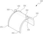
도 6 내지 도 8을 참조하면, 상부 하우징(130)은 상부 코어(220)가 내장되는 상부 수용 공간(131)이 내부에 형성된다. 이때, 상부 하우징(130)은 상부에 장력 부재(140)가 결합되는 장력 부재 결합 홈(132)이 형성될 수도 있다. 즉, 상부 하우징(130)의 내부에 형성된 상부 수용 홈의 상부에는 소정 형상의 장력 부재 결합 홈(132)이 형성된다.Referring to Figures 6 to 8, the
상부 하우징(130)은 반원통형의 양단이 연장된 형상의 상부 코어(220)가 실장되기 때문에 상부가 반원통형으로 형성된다. 이때, 상부 하우징(130)은 하부(즉, 본체 하우징(110)에 접촉되는 부분)에 선로가 실장되는 선로 수용 홈(133)이 형성된다.The
그에 따라, 상부 하우징(130)은 소정 지름을 갖는 반원통형 및 육면체가 결합된 형상으로 형성되며, 소정 지름을 갖는 반원통형 및 육면체가 결합된 형상의 선로 수용 홈(133)이 형성된다. 여기서, 선로 수용 홈(133)의 반원통형 부분은 선로에 사용되는 전력선의 최대치를 고려하여 설정될 수 있으며, 상부 하우징(130)의 반원통형 부분 보다 작은 지름을 갖는다.Accordingly, the
이때, 상부 하우징(130)의 반원통형 부분은 선로 수용 홈(133)의 반원통형 형상에 비해 큰 지름을 갖도록 형성된다. 상부 하우징(130)은 선로 수용 홈(133)이 형성됨에 따라 하부(즉, 육면체 형상의 하부 방향) 일부에 개구부가 형성된다.At this time, the semi-cylindrical portion of the
상부 하우징(130)은 선로 수용 홈(133)이 형성된 하부에 지지 수단(150)과 결합되는 지지 수단 결합 홈(134)이 형성된다. 즉, 상부 하우징(130)은 선로 수용 홈(133)에 인접한 양측면에 지지 수단 결합 홈(134)이 형성되어, 지지 수단(150)과 결합된다.The
상부 하우징(130)은 일측에 하부 힌지 수단(115)에 대응되는 상부 힌지 수단(135)이 형성된다. 이때, 상부 하우징(130)의 일측에서 외부 방향으로 연장된 상부 연장부(136)가 형성된다. 상부 힌지 수단(135)은 상부 연장부(136)의 하부에서 하부 방향(즉, 본체 하우징(110) 방향)으로 연장되어 형성된다. 상부 힌지 수단(135)은 하부 힌지 수단(115)에 대응되는 구조로 형성되며, 하부 힌지 수단(115)과 결합된 후 힌지 핀(240)이 삽입되는 힌지 핀 삽입 홀(135a)이 형성된다.The
상부 하우징(130)은 타측에 본체 하우징(110)과의 결합을 위한 상부 체결 수단(137)을 구비한다. 즉, 상부 하우징(130)은 상부 힌지 수단(135)이 형성된 일측에 대향되는 타측의 하부에 상부 체결 수단(137)이 형성된다. 이때, 상부 체결 수단(137)은 상부 하우징(130)의 타측 하부에서 외부 방향으로 연장되어 형성된다. 상부 체결 수단(137)은 하부 체결 수단(116)에 대응되는 구조로 형성되며, 본체 하우징(110)과 상부 하우징(130)이 결합된 후 체결 핀(250; 예를 들면, 볼트 등)이 삽입되는 체결 핀 삽입 홀(137a)이 형성된다. 여기서, 체결 핀 삽입 홀(137a)의 내벽에는 체결 핀(250)에 대응되는 나사산이 형성될 수도 있다.The
도 9를 참조하면, 장력 부재(140)는 라운드 형상의 굴곡을 갖는 판상으로 형성된다. 장력 부재(140)는 양단이 상부 방향으로 굴곡되어 상부 하우징(130)에 형성된 장력 부재 결합 홈(132)에 삽입되어, 상부 하우징(130)에 결합된다. 그에 따라, 장력 부재(140)는 상부 하우징(130)에 수용되는 상부 코어(220)에 하부 방향(즉, 본체 하우징(110) 방향)으로 장력을 가하여 상부 코어(220) 및 하부 코어(210) 간의 결합력을 증대시킨다.Referring to FIG. 9, the
장력 부재(140)는 양단에 고정 수단(141)이 형성될 수 있다. 증, 장력 부재 결합 홈(132)과 장력 부재(140)의 결합력을 높이기 위해서, 장력 부재(140)의 양단에 고정 수단(141)이 형성될 수 있다.The
도 10을 참조하면, 지지 수단(150)은 선로 수용 홈(133)에 대응되는 형상으로 형성되어, 상부 하우징(130)의 하부(즉, 선로 수용 홈(133))에 결합된다. 즉, 지지 수단(150)은 원호(圓弧)의 양단이 하부 방향으로 연장된 형상으로 형성된다. 이때, 지지 수단(150)의 양측부에는 상부 하우징(130)에 수용되는 상부 코어(220)를 지지 및 가이드하는 가이드 돌기(151)가 상부 방향으로 연장되어 형성될 수 있다.Referring to FIG. 10, the support means 150 is formed in a shape corresponding to the track receiving groove 133 and is coupled to the lower portion of the upper housing 130 (i.e., the track receiving groove 133). That is, the support means 150 is formed in a shape in which both ends of a circular arc extend downward. At this time, guide
지지 수단(150)의 상부 중앙에는 상부 방향으로 연장되어 형성되는 고정용 연장부(152)가 형성될 수 있다. 이때, 고정용 연장부(152)에는 상부 하우징(130)의 지지 수단 결합 홈(134)과 결합되는 지지 수단 고정용 돌기(153)가 형성된다. 여기서, 지지 수단 고정용 돌기(153)들은 하부 방향으로 갈수록 상호 간의 이격 거리가 감소하는 경사가 형성될 수 있다.A fixing
상술한 구성에 의해, 변류기(100)는 본체 하우징(110)과 상부 하우징(130)을 결합시 힌지 수단을 통해 일측이 회동 가능한 상태로 결합되고 타측이 체결 수단에 의해 체결됨으로써, 한 명의 작업자가 변류기(100)를 선로에 설치하기 용이한 효과가 있다. 즉, 변류기(100)는 일측이 힌지 수단으로 결합되어 있는 상태에서 타측의 체결 부재를 이용하여 선로에 설치할 수 있기 때문에 양측을 모두 체결해야 하는 종래의 변류기(100)에 비해 설치가 용이한 효과가 있다.With the above-described configuration, when the
또한, 변류기(100)는 힌지 수단 및 체결 수단을 이용해 선로에 설치됨으로써, 상부 코어(220) 및 하부 코어(210)의 단면들이 일정한 압력으로 결합할 수 있는 효과가 있다.In addition, the
또한, 변류기(100)는 일측이 힌지 수단으로 결합된 상태에서 타측의 체결 수단을 통해 선로에 설치되기 때문에 상부 코어(220) 및 하부 코어(210)의 양쪽 단면에 동일한 힘을 가하여 변류기(100) 성능의 저하를 방지할 수 있다.In addition, since the
또한, 변류기(100)는 하부 코어(210)의 일단이 삽입되는 관통 홀이 형성된 보빈 커버(120)를 본체 하우징(110)에 결합함으로써, 하부 코어(210)의 위치를 정확하게 유지하고, 진동에 의한 하부 코어(210)의 이탈(이동)을 방지할 수 있는 효과가 있다.In addition, the
또한, 변류기(100)는 하부 코어(210)의 일단이 삽입되는 관통 홀이 형성된 보빈 커버(120)를 본체 하우징(110)에 결합하여 하부 코어(210)의 이탈(이동)을 방지함으로써, 상부 코어(220)와 하부 코어(210)가 정확한 위치에서 결합되어 변류기(100)의 성능을 최적 상태로 유지할 수 있는 효과가 있다.In addition, the
또한, 변류기(100)는 힌지 수단 및 체결 수단을 이용한 선로에 설치되고, 보빈 커버(120)를 통해 하부 코어(210)의 이탈(이동)을 방지함으로써, 작업자가 하부 코어(210) 및 상부 코어(220)의 정렬 상태 및 가해지는 힘을 고려하지 않고 간단한 조작으로 설치할 수 있어 변류기(100)의 성능 구현 및 유지 보수가 용이한 효과가 있다.In addition, the
이상에서 본 발명에 따른 바람직한 실시예에 대해 설명하였으나, 다양한 형태로 변형이 가능하며, 본 기술분야에서 통상의 지식을 가진자라면 본 발명의 특허청구범위를 벗어남이 없이 다양한 변형예 및 수정예를 실시할 수 있을 것으로 이해된다.Although the preferred embodiment according to the present invention has been described above, it can be modified into various forms, and those skilled in the art can make various variations and modifications without departing from the scope of the patent claims of the present invention. It is understood that it can be implemented.
100: 변류기110: 본체 하우징
120: 보빈 커버130: 상부 하우징
140: 장력 부재150: 지지 수단
210: 하부 코어220: 상부 코어
230: 보빈240: 힌지 핀
250: 체결 핀100: current transformer 110: main housing
120: bobbin cover 130: upper housing
140: Tension member 150: Support means
210: lower core 220: upper core
230: bobbin 240: hinge pin
250: fastening pin
Claims (12)
Translated fromKorean상기 본체 하우징의 상면에 결합되어, 상기 본체 하우징의 상면의 적어도 일부를 덮는 보빈 커버; 및
다른 마그네틱 코어가 수용되고, 선로가 수용되는 선로 수용 홈이 형성되는 상부 하우징을 포함하고,
상기 상부 하우징 및 상기 본체 하우징의 일측은 힌지 부재로 결합되며,
상기 보빈 커버는 상기 마그네틱 코어의 단부가 관통하는 코어 관통 홀이 형성된 변류기.a main housing in which the magnetic core is accommodated;
a bobbin cover coupled to the upper surface of the main body housing and covering at least a portion of the upper surface of the main body housing; and
It includes an upper housing in which another magnetic core is received and a track receiving groove in which the track is received is formed,
One side of the upper housing and the main housing is coupled with a hinge member,
The bobbin cover is a current transformer in which a core through-hole is formed through which an end of the magnetic core passes.
상기 본체 하우징은 일측에 하부 힌지 수단을 구비하고, 타측에 하부 체결 수단을 구비하며,
상기 상부 하우징은 일측에 상기 하부 힌지 수단과 결합되는 상부 힌지 수단을 구비하고, 타측에 상기 하부 체결 수단과 결합되는 상부 체결 수단을 구비하는 변류기.According to paragraph 1,
The main housing has a lower hinge means on one side and a lower fastening means on the other side,
A current transformer wherein the upper housing has an upper hinge means coupled with the lower hinge means on one side, and an upper fastening means coupled with the lower fastening means on the other side.
상기 하부 힌지 수단과 상기 상부 힌지 수단은 힌지 핀이 삽입되는 힌지 핀 삽입 홀이 형성되어 힌지 핀을 통해 회동 가능한 상태로 결합되고,
상기 하부 체결 수단과 상기 상부 체결 수단은 체결 핀이 삽입되는 체결 핀 삽입 홀이 형성되어 체결 핀을 통해 결합되는 변류기.According to paragraph 2,
The lower hinge means and the upper hinge means have a hinge pin insertion hole into which a hinge pin is inserted, and are rotatably coupled through a hinge pin,
A current transformer in which the lower fastening means and the upper fastening means are coupled through a fastening pin by forming a fastening pin insertion hole into which the fastening pin is inserted.
상기 본체 하우징에 수용되는 마그네틱 코어는 단부의 일부가 상기 본체 하우징의 상부로 노출되는 변류기.According to paragraph 1,
A current transformer in which a portion of an end of the magnetic core accommodated in the main housing is exposed to the upper part of the main housing.
상부 선로 수용 홈은 반원통형 및 육면체가 결합된 형상인 변류기.According to paragraph 1,
A current transformer in which the upper line receiving groove is a combination of a semi-cylindrical shape and a hexahedron shape.
라운드 형상의 굴곡을 갖는 판상으로 형성되어 상기 상부 하우징과 상기 다른 마그네틱 코어 사이에 개재되고, 상기 다른 마그네틱 코어에 하부 방향으로 장력을 가하는 장력 부재를 더 포함하는 변류기.According to paragraph 1,
The current transformer is formed in a plate shape with a round bend and is interposed between the upper housing and the other magnetic core, and further includes a tension member that applies tension to the other magnetic core in a downward direction.
상기 상부 하우징은 장력 부재 결합 홈이 형성되고,
상기 장력 부재의 양단은 상기 장력 부재 결합 홈에 결합되는 변류기.According to clause 8,
The upper housing is formed with a tension member coupling groove,
A current transformer wherein both ends of the tension member are coupled to the tension member coupling groove.
상기 선로 수용 홈에 대응되는 형상으로 형성되어 상기 선로 수용 홈에 결합되고, 상기 다른 마그네틱 코어의 하부를 지지하는 지지 수단을 더 포함하는 변류기.According to paragraph 1,
A current transformer further comprising a support means formed in a shape corresponding to the line receiving groove, coupled to the line receiving groove, and supporting a lower portion of the other magnetic core.
상기 상부 하우징은 지지 수단 결합 홈이 형성되고,
상기 지지 수단은 상기 지지 수단 결합 홈에 결합되는 지지 수단 고정용 돌기가 형성되는 변류기.According to clause 10,
The upper housing is formed with a support means coupling groove,
A current transformer wherein the support means is formed with a protrusion for fixing the support means coupled to the support means coupling groove.
상기 지지 수단은 측부에서 상부로 연장되는 가이드 돌기가 형성되는 변류기.According to clause 10,
The support means is a current transformer in which a guide protrusion extending from the side to the top is formed.
Priority Applications (1)
| Application Number | Priority Date | Filing Date | Title |
|---|---|---|---|
| KR1020160100171AKR102622224B1 (en) | 2016-08-05 | 2016-08-05 | Current transformer |
Applications Claiming Priority (1)
| Application Number | Priority Date | Filing Date | Title |
|---|---|---|---|
| KR1020160100171AKR102622224B1 (en) | 2016-08-05 | 2016-08-05 | Current transformer |
Publications (2)
| Publication Number | Publication Date |
|---|---|
| KR20180016135A KR20180016135A (en) | 2018-02-14 |
| KR102622224B1true KR102622224B1 (en) | 2024-01-08 |
Family
ID=61229830
Family Applications (1)
| Application Number | Title | Priority Date | Filing Date |
|---|---|---|---|
| KR1020160100171AActiveKR102622224B1 (en) | 2016-08-05 | 2016-08-05 | Current transformer |
Country Status (1)
| Country | Link |
|---|---|
| KR (1) | KR102622224B1 (en) |
Families Citing this family (3)
| Publication number | Priority date | Publication date | Assignee | Title |
|---|---|---|---|---|
| CN108957094A (en)* | 2018-05-08 | 2018-12-07 | 湖南银河电气有限公司 | A kind of open-close type current sensor and its assemble method based on magnetic modulation |
| KR102369617B1 (en)* | 2020-01-02 | 2022-03-03 | 주식회사 폰 | Current transformer for high output power supply easily installed in underground transmission line with improved waterproof/dustproof function |
| CN114121437A (en)* | 2021-11-03 | 2022-03-01 | 国网山东省电力公司临沂供电公司 | An open current transformer |
Citations (4)
| Publication number | Priority date | Publication date | Assignee | Title |
|---|---|---|---|---|
| KR200369004Y1 (en)* | 2004-09-15 | 2004-12-03 | 주식회사 평일 | Clamp current transformer |
| JP2012212837A (en) | 2011-03-30 | 2012-11-01 | Kohshin Electric Corp | Split-type current transformer |
| WO2015044899A1 (en) | 2013-09-30 | 2015-04-02 | Lem Intellectual Property Sa | Clip-on current transducer or current transformer |
| KR101586785B1 (en) | 2015-11-16 | 2016-02-02 | 주식회사 페라리스파워 | Separable current transformer |
Family Cites Families (1)
| Publication number | Priority date | Publication date | Assignee | Title |
|---|---|---|---|---|
| KR200371971Y1 (en) | 2004-10-21 | 2005-01-06 | (주)시티이텍 | Split current transformer |
- 2016
- 2016-08-05KRKR1020160100171Apatent/KR102622224B1/enactiveActive
Patent Citations (4)
| Publication number | Priority date | Publication date | Assignee | Title |
|---|---|---|---|---|
| KR200369004Y1 (en)* | 2004-09-15 | 2004-12-03 | 주식회사 평일 | Clamp current transformer |
| JP2012212837A (en) | 2011-03-30 | 2012-11-01 | Kohshin Electric Corp | Split-type current transformer |
| WO2015044899A1 (en) | 2013-09-30 | 2015-04-02 | Lem Intellectual Property Sa | Clip-on current transducer or current transformer |
| KR101586785B1 (en) | 2015-11-16 | 2016-02-02 | 주식회사 페라리스파워 | Separable current transformer |
Also Published As
| Publication number | Publication date |
|---|---|
| KR20180016135A (en) | 2018-02-14 |
Similar Documents
| Publication | Publication Date | Title |
|---|---|---|
| KR102622224B1 (en) | Current transformer | |
| US8922318B1 (en) | Transformer structure | |
| KR102225868B1 (en) | Spacer for cable tray | |
| CN105051838B (en) | transformer | |
| KR100550296B1 (en) | Junction box | |
| KR200467192Y1 (en) | Apparatus for fastening an antenna for a vehicle | |
| KR102015853B1 (en) | Cable tray of apartment building | |
| KR101586709B1 (en) | Raceway for mounting lighting instruments | |
| KR102793103B1 (en) | Bobbin and transformer with the same | |
| KR101038564B1 (en) | Busbar connection device of switchboard and distribution board | |
| KR102734829B1 (en) | Rack for supporting electric cables | |
| JP2016101020A (en) | Seismic isolator for switch board and construction method of switch board | |
| KR20240025572A (en) | Bobbin and transformer with the same | |
| US9780508B2 (en) | Test cable and socket adapter for a test cable | |
| KR101487889B1 (en) | Connected devices for Cable wiring tray | |
| CN102544785A (en) | A device for positioning at least one multiple round plug | |
| KR101268194B1 (en) | Apparatus for mounting sticked matter on wall | |
| KR20140003753U (en) | Cover for cable tray | |
| KR102247853B1 (en) | Mechanism installation reinforcement with a metal flexible wire tube connector for fixing M-bar | |
| KR200451739Y1 (en) | Wiring box with fixing member | |
| KR20140005495U (en) | Cable tray | |
| JP2015159181A (en) | Housing mounting structure and mounting tool used therefor | |
| KR101922153B1 (en) | Transformer | |
| KR101150439B1 (en) | Integrated terminal box for ultrahigh speedunification wiring | |
| KR20090008231U (en) | Sleeve terminal block |
Legal Events
| Date | Code | Title | Description |
|---|---|---|---|
| PA0109 | Patent application | Patent event code:PA01091R01D Comment text:Patent Application Patent event date:20160805 | |
| PG1501 | Laying open of application | ||
| PA0201 | Request for examination | Patent event code:PA02012R01D Patent event date:20210721 Comment text:Request for Examination of Application Patent event code:PA02011R01I Patent event date:20160805 Comment text:Patent Application | |
| E902 | Notification of reason for refusal | ||
| PE0902 | Notice of grounds for rejection | Comment text:Notification of reason for refusal Patent event date:20230415 Patent event code:PE09021S01D | |
| E701 | Decision to grant or registration of patent right | ||
| PE0701 | Decision of registration | Patent event code:PE07011S01D Comment text:Decision to Grant Registration Patent event date:20231005 | |
| GRNT | Written decision to grant | ||
| PR0701 | Registration of establishment | Comment text:Registration of Establishment Patent event date:20240103 Patent event code:PR07011E01D | |
| PR1002 | Payment of registration fee | Payment date:20240103 End annual number:3 Start annual number:1 | |
| PG1601 | Publication of registration |