KR102621759B1 - Aerosol generating device - Google Patents
Aerosol generating deviceDownload PDFInfo
- Publication number
- KR102621759B1 KR102621759B1KR1020210064734AKR20210064734AKR102621759B1KR 102621759 B1KR102621759 B1KR 102621759B1KR 1020210064734 AKR1020210064734 AKR 1020210064734AKR 20210064734 AKR20210064734 AKR 20210064734AKR 102621759 B1KR102621759 B1KR 102621759B1
- Authority
- KR
- South Korea
- Prior art keywords
- temperature
- heating unit
- generating device
- aerosol generating
- current
- Prior art date
- Legal status (The legal status is an assumption and is not a legal conclusion. Google has not performed a legal analysis and makes no representation as to the accuracy of the status listed.)
- Active
Links
- 239000000443aerosolSubstances0.000titleclaimsabstractdescription114
- 238000010438heat treatmentMethods0.000claimsabstractdescription174
- 239000000758substrateSubstances0.000claimsabstractdescription6
- 238000000034methodMethods0.000claimsdescription36
- 235000019504cigarettesNutrition0.000description45
- 241000208125NicotianaSpecies0.000description27
- 235000002637Nicotiana tabacumNutrition0.000description27
- 239000007788liquidSubstances0.000description25
- 239000006200vaporizerSubstances0.000description16
- 239000000203mixtureSubstances0.000description12
- 238000010586diagramMethods0.000description11
- 238000001514detection methodMethods0.000description10
- 239000002775capsuleSubstances0.000description9
- 239000000796flavoring agentSubstances0.000description9
- 230000000391smoking effectEffects0.000description9
- 230000006870functionEffects0.000description8
- 230000006698inductionEffects0.000description7
- DNIAPMSPPWPWGF-UHFFFAOYSA-NPropylene glycolChemical compoundCC(O)CODNIAPMSPPWPWGF-UHFFFAOYSA-N0.000description6
- 235000019634flavorsNutrition0.000description6
- 239000000463materialSubstances0.000description6
- 239000004020conductorSubstances0.000description5
- PEDCQBHIVMGVHV-UHFFFAOYSA-NGlycerineChemical compoundOCC(O)COPEDCQBHIVMGVHV-UHFFFAOYSA-N0.000description4
- 238000004590computer programMethods0.000description4
- 239000003205fragranceSubstances0.000description4
- LYCAIKOWRPUZTN-UHFFFAOYSA-NEthylene glycolChemical compoundOCCOLYCAIKOWRPUZTN-UHFFFAOYSA-N0.000description3
- 239000000919ceramicSubstances0.000description3
- MTHSVFCYNBDYFN-UHFFFAOYSA-Ndiethylene glycolChemical compoundOCCOCCOMTHSVFCYNBDYFN-UHFFFAOYSA-N0.000description3
- 235000013355food flavoring agentNutrition0.000description3
- 229910052751metalInorganic materials0.000description3
- 239000002184metalSubstances0.000description3
- 239000000126substanceSubstances0.000description3
- NOOLISFMXDJSKH-UTLUCORTSA-N(+)-NeomentholChemical compoundCC(C)[C@@H]1CC[C@@H](C)C[C@@H]1ONOOLISFMXDJSKH-UTLUCORTSA-N0.000description2
- GVJHHUAWPYXKBD-UHFFFAOYSA-N(±)-α-TocopherolChemical compoundOC1=C(C)C(C)=C2OC(CCCC(C)CCCC(C)CCCC(C)C)(C)CCC2=C1CGVJHHUAWPYXKBD-UHFFFAOYSA-N0.000description2
- CIWBSHSKHKDKBQ-JLAZNSOCSA-NAscorbic acidChemical compoundOC[C@H](O)[C@H]1OC(=O)C(O)=C1OCIWBSHSKHKDKBQ-JLAZNSOCSA-N0.000description2
- NOOLISFMXDJSKH-UHFFFAOYSA-NDL-mentholNatural productsCC(C)C1CCC(C)CC1ONOOLISFMXDJSKH-UHFFFAOYSA-N0.000description2
- LFQSCWFLJHTTHZ-UHFFFAOYSA-NEthanolChemical compoundCCOLFQSCWFLJHTTHZ-UHFFFAOYSA-N0.000description2
- 238000013461designMethods0.000description2
- 239000011888foilSubstances0.000description2
- 235000011187glycerolNutrition0.000description2
- 239000004615ingredientSubstances0.000description2
- 229940041616mentholDrugs0.000description2
- 238000012546transferMethods0.000description2
- 230000000007visual effectEffects0.000description2
- 229930003231vitaminNatural products0.000description2
- 239000011782vitaminSubstances0.000description2
- 235000013343vitaminNutrition0.000description2
- 229940088594vitaminDrugs0.000description2
- 150000003722vitamin derivativesChemical class0.000description2
- ALSTYHKOOCGGFT-KTKRTIGZSA-N(9Z)-octadecen-1-olChemical compoundCCCCCCCC\C=C/CCCCCCCCOALSTYHKOOCGGFT-KTKRTIGZSA-N0.000description1
- FPIPGXGPPPQFEQ-UHFFFAOYSA-N13-cis retinolNatural productsOCC=C(C)C=CC=C(C)C=CC1=C(C)CCCC1(C)CFPIPGXGPPPQFEQ-UHFFFAOYSA-N0.000description1
- 229920000742CottonPolymers0.000description1
- ZZZCUOFIHGPKAK-UHFFFAOYSA-ND-erythro-ascorbic acidNatural productsOCC1OC(=O)C(O)=C1OZZZCUOFIHGPKAK-UHFFFAOYSA-N0.000description1
- HBBGRARXTFLTSG-UHFFFAOYSA-NLithium ionChemical compound[Li+]HBBGRARXTFLTSG-UHFFFAOYSA-N0.000description1
- 244000246386Mentha pulegiumSpecies0.000description1
- 235000016257Mentha pulegiumNutrition0.000description1
- 235000004357Mentha x piperitaNutrition0.000description1
- 239000004909MoisturizerSubstances0.000description1
- UWHCKJMYHZGTIT-UHFFFAOYSA-NTetraethylene glycol,Natural productsOCCOCCOCCOCCOUWHCKJMYHZGTIT-UHFFFAOYSA-N0.000description1
- FPIPGXGPPPQFEQ-BOOMUCAASA-NVitamin ANatural productsOC/C=C(/C)\C=C\C=C(\C)/C=C/C1=C(C)CCCC1(C)CFPIPGXGPPPQFEQ-BOOMUCAASA-N0.000description1
- 229930003270Vitamin BNatural products0.000description1
- 229930003268Vitamin CNatural products0.000description1
- 229930003427Vitamin ENatural products0.000description1
- 239000000654additiveSubstances0.000description1
- FPIPGXGPPPQFEQ-OVSJKPMPSA-Nall-trans-retinolChemical compoundOC\C=C(/C)\C=C\C=C(/C)\C=C\C1=C(C)CCCC1(C)CFPIPGXGPPPQFEQ-OVSJKPMPSA-N0.000description1
- 229910052782aluminiumInorganic materials0.000description1
- XAGFODPZIPBFFR-UHFFFAOYSA-NaluminiumChemical compound[Al]XAGFODPZIPBFFR-UHFFFAOYSA-N0.000description1
- 238000000889atomisationMethods0.000description1
- 238000003763carbonizationMethods0.000description1
- 238000010000carbonizingMethods0.000description1
- 229920002301cellulose acetatePolymers0.000description1
- SZXQTJUDPRGNJN-UHFFFAOYSA-Ndipropylene glycolChemical compoundOCCCOCCCOSZXQTJUDPRGNJN-UHFFFAOYSA-N0.000description1
- 238000005516engineering processMethods0.000description1
- 239000000835fiberSubstances0.000description1
- 239000008369fruit flavorSubstances0.000description1
- WIGCFUFOHFEKBI-UHFFFAOYSA-Ngamma-tocopherolNatural productsCC(C)CCCC(C)CCCC(C)CCCC1CCC2C(C)C(O)C(C)C(C)C2O1WIGCFUFOHFEKBI-UHFFFAOYSA-N0.000description1
- 239000003365glass fiberSubstances0.000description1
- 239000008187granular materialSubstances0.000description1
- 235000001050hortel pimentaNutrition0.000description1
- 239000003906humectantSubstances0.000description1
- 238000003780insertionMethods0.000description1
- 230000037431insertionEffects0.000description1
- 229910001416lithium ionInorganic materials0.000description1
- 239000001683mentha spicata herb oilSubstances0.000description1
- 238000012986modificationMethods0.000description1
- 230000004048modificationEffects0.000description1
- 230000001333moisturizerEffects0.000description1
- 229910001120nichromeInorganic materials0.000description1
- 229940055577oleyl alcoholDrugs0.000description1
- XMLQWXUVTXCDDL-UHFFFAOYSA-Noleyl alcoholNatural productsCCCCCCC=CCCCCCCCCCCOXMLQWXUVTXCDDL-UHFFFAOYSA-N0.000description1
- 230000003287optical effectEffects0.000description1
- 150000007524organic acidsChemical class0.000description1
- 235000005985organic acidsNutrition0.000description1
- 239000000419plant extractSubstances0.000description1
- 230000035807sensationEffects0.000description1
- 235000019615sensationsNutrition0.000description1
- 239000002904solventSubstances0.000description1
- 235000019721spearmint oilNutrition0.000description1
- 238000005507sprayingMethods0.000description1
- ZIBGPFATKBEMQZ-UHFFFAOYSA-Ntriethylene glycolChemical compoundOCCOCCOCCOZIBGPFATKBEMQZ-UHFFFAOYSA-N0.000description1
- 235000019155vitamin ANutrition0.000description1
- 239000011719vitamin ASubstances0.000description1
- 235000019156vitamin BNutrition0.000description1
- 239000011720vitamin BSubstances0.000description1
- 235000019154vitamin CNutrition0.000description1
- 239000011718vitamin CSubstances0.000description1
- 235000019165vitamin ENutrition0.000description1
- 229940046009vitamin EDrugs0.000description1
- 239000011709vitamin ESubstances0.000description1
- 229940045997vitamin aDrugs0.000description1
- XLYOFNOQVPJJNP-UHFFFAOYSA-NwaterSubstancesOXLYOFNOQVPJJNP-UHFFFAOYSA-N0.000description1
Images


Classifications
- A—HUMAN NECESSITIES
- A24—TOBACCO; CIGARS; CIGARETTES; SIMULATED SMOKING DEVICES; SMOKERS' REQUISITES
- A24F—SMOKERS' REQUISITES; MATCH BOXES; SIMULATED SMOKING DEVICES
- A24F40/00—Electrically operated smoking devices; Component parts thereof; Manufacture thereof; Maintenance or testing thereof; Charging means specially adapted therefor
- A24F40/50—Control or monitoring
- A—HUMAN NECESSITIES
- A24—TOBACCO; CIGARS; CIGARETTES; SIMULATED SMOKING DEVICES; SMOKERS' REQUISITES
- A24D—CIGARS; CIGARETTES; TOBACCO SMOKE FILTERS; MOUTHPIECES FOR CIGARS OR CIGARETTES; MANUFACTURE OF TOBACCO SMOKE FILTERS OR MOUTHPIECES
- A24D1/00—Cigars; Cigarettes
- A24D1/20—Cigarettes specially adapted for simulated smoking devices
- A—HUMAN NECESSITIES
- A24—TOBACCO; CIGARS; CIGARETTES; SIMULATED SMOKING DEVICES; SMOKERS' REQUISITES
- A24F—SMOKERS' REQUISITES; MATCH BOXES; SIMULATED SMOKING DEVICES
- A24F40/00—Electrically operated smoking devices; Component parts thereof; Manufacture thereof; Maintenance or testing thereof; Charging means specially adapted therefor
- A24F40/10—Devices using liquid inhalable precursors
- A—HUMAN NECESSITIES
- A24—TOBACCO; CIGARS; CIGARETTES; SIMULATED SMOKING DEVICES; SMOKERS' REQUISITES
- A24F—SMOKERS' REQUISITES; MATCH BOXES; SIMULATED SMOKING DEVICES
- A24F40/00—Electrically operated smoking devices; Component parts thereof; Manufacture thereof; Maintenance or testing thereof; Charging means specially adapted therefor
- A24F40/40—Constructional details, e.g. connection of cartridges and battery parts
- A24F40/46—Shape or structure of electric heating means
- A—HUMAN NECESSITIES
- A24—TOBACCO; CIGARS; CIGARETTES; SIMULATED SMOKING DEVICES; SMOKERS' REQUISITES
- A24F—SMOKERS' REQUISITES; MATCH BOXES; SIMULATED SMOKING DEVICES
- A24F40/00—Electrically operated smoking devices; Component parts thereof; Manufacture thereof; Maintenance or testing thereof; Charging means specially adapted therefor
- A24F40/40—Constructional details, e.g. connection of cartridges and battery parts
- A24F40/48—Fluid transfer means, e.g. pumps
- A24F40/485—Valves; Apertures
- A—HUMAN NECESSITIES
- A24—TOBACCO; CIGARS; CIGARETTES; SIMULATED SMOKING DEVICES; SMOKERS' REQUISITES
- A24F—SMOKERS' REQUISITES; MATCH BOXES; SIMULATED SMOKING DEVICES
- A24F40/00—Electrically operated smoking devices; Component parts thereof; Manufacture thereof; Maintenance or testing thereof; Charging means specially adapted therefor
- A24F40/50—Control or monitoring
- A24F40/51—Arrangement of sensors
- A—HUMAN NECESSITIES
- A24—TOBACCO; CIGARS; CIGARETTES; SIMULATED SMOKING DEVICES; SMOKERS' REQUISITES
- A24F—SMOKERS' REQUISITES; MATCH BOXES; SIMULATED SMOKING DEVICES
- A24F40/00—Electrically operated smoking devices; Component parts thereof; Manufacture thereof; Maintenance or testing thereof; Charging means specially adapted therefor
- A24F40/50—Control or monitoring
- A24F40/57—Temperature control
- A—HUMAN NECESSITIES
- A24—TOBACCO; CIGARS; CIGARETTES; SIMULATED SMOKING DEVICES; SMOKERS' REQUISITES
- A24F—SMOKERS' REQUISITES; MATCH BOXES; SIMULATED SMOKING DEVICES
- A24F40/00—Electrically operated smoking devices; Component parts thereof; Manufacture thereof; Maintenance or testing thereof; Charging means specially adapted therefor
- A24F40/60—Devices with integrated user interfaces
- G—PHYSICS
- G05—CONTROLLING; REGULATING
- G05B—CONTROL OR REGULATING SYSTEMS IN GENERAL; FUNCTIONAL ELEMENTS OF SUCH SYSTEMS; MONITORING OR TESTING ARRANGEMENTS FOR SUCH SYSTEMS OR ELEMENTS
- G05B11/00—Automatic controllers
- G05B11/01—Automatic controllers electric
- G05B11/36—Automatic controllers electric with provision for obtaining particular characteristics, e.g. proportional, integral, differential
- G05B11/42—Automatic controllers electric with provision for obtaining particular characteristics, e.g. proportional, integral, differential for obtaining a characteristic which is both proportional and time-dependent, e.g. P. I., P. I. D.
- H—ELECTRICITY
- H02—GENERATION; CONVERSION OR DISTRIBUTION OF ELECTRIC POWER
- H02J—CIRCUIT ARRANGEMENTS OR SYSTEMS FOR SUPPLYING OR DISTRIBUTING ELECTRIC POWER; SYSTEMS FOR STORING ELECTRIC ENERGY
- H02J7/00—Circuit arrangements for charging or depolarising batteries or for supplying loads from batteries
- H02J7/007—Regulation of charging or discharging current or voltage
- H—ELECTRICITY
- H05—ELECTRIC TECHNIQUES NOT OTHERWISE PROVIDED FOR
- H05B—ELECTRIC HEATING; ELECTRIC LIGHT SOURCES NOT OTHERWISE PROVIDED FOR; CIRCUIT ARRANGEMENTS FOR ELECTRIC LIGHT SOURCES, IN GENERAL
- H05B1/00—Details of electric heating devices
- H05B1/02—Automatic switching arrangements specially adapted to apparatus ; Control of heating devices
Landscapes
- Engineering & Computer Science (AREA)
- Human Computer Interaction (AREA)
- Physics & Mathematics (AREA)
- General Physics & Mathematics (AREA)
- Automation & Control Theory (AREA)
- Power Engineering (AREA)
- Catching Or Destruction (AREA)
Abstract
Translated fromKoreanDescription
Translated fromKorean본 발명은 에어로졸 생성 장치에 관한 것으로서, 보다 구체적으로, 가열부에 공급되는 전력을 제어하는 제어부의 제어방식을 통해서 배터리 손상을 방지할 수 있는 에어로졸 생성 장치에 관한 것이다.The present invention relates to an aerosol generating device, and more specifically, to an aerosol generating device that can prevent battery damage through a control method of a control unit that controls the power supplied to the heating unit.
근래에 일반적인 궐련의 단점들을 극복하는 대체 방법에 관한 수요가 증가하고 있다. 예를 들어, 궐련을 연소시켜 에어로졸을 생성시키는 방법이 아닌 궐련 또는 액체 저장부 내의 에어로졸 생성물질이 가열됨에 따라 에어로졸을 생성하는 방법에 관한 수요가 증가하고 있다.In recent years, there has been an increasing demand for alternative methods to overcome the disadvantages of regular cigarettes. For example, there is an increasing demand for a method of generating an aerosol by heating the aerosol-generating material in the cigarette or liquid storage unit, rather than a method of generating an aerosol by burning a cigarette.
이러한 에어로졸 생성 장치에 탑재되는 히터는 PID(Proportional-Integral-Derivative) 제어 방식에 히터를 가열될 수 있으나, 히터를 가열 초기부터 PID 제어 방식으로 가열하는 경우, 배터리에 과부하가 발생될 수 있다.The heater mounted on such an aerosol generating device can be heated using a PID (Proportional-Integral-Derivative) control method. However, if the heater is heated using a PID control method from the beginning of heating, overload may occur in the battery.
본 발명이 해결하고자 하는 기술적 과제는, 배터리의 손상을 방지할 수 있는 에어로졸 생성 장치를 제공하는 데에 있다.The technical problem to be solved by the present invention is to provide an aerosol generating device that can prevent damage to batteries.
본 발명의 기술적 과제는 상술한 바에 한정되지 않으며 이하의 예들로부터 또 다른 기술적 과제들이 유추될 수 있다.The technical problems of the present invention are not limited to what has been described above, and other technical problems can be inferred from the examples below.
상기 기술적 과제를 해결하기 위한 본 발명의 일 실시 예에 따른 장치는, 에어로졸 생성 장치로서, 에어로졸 생성 기질을 가열하여 에어로졸을 생성시키는 가열부; 및 상기 가열부에 공급되는 전력을 제어하는 제어부를 포함하고, 상기 제어부는, 상기 가열부에 공급되는 전류의 크기를 조절하여 상기 가열부의 온도가 기설정된 기준 온도까지 상승되도록 제어하고, 상기 가열부의 온도가 상기 기준 온도에 도달하면, 상기 가열부의 온도와 목표 온도의 차이값을 기초로 상기 가열부의 온도가 상기 기준 온도부터 목표 온도까지 상승되도록 제어한다.A device according to an embodiment of the present invention for solving the above technical problem is an aerosol generating device, comprising: a heating unit that heats an aerosol generating substrate to generate an aerosol; and a control unit that controls the power supplied to the heating unit, wherein the control unit controls the size of the current supplied to the heating unit to raise the temperature of the heating unit to a preset reference temperature, and controls the heating unit to increase the temperature of the heating unit to a preset reference temperature. When the temperature reaches the reference temperature, the temperature of the heating unit is controlled to rise from the reference temperature to the target temperature based on the difference between the temperature of the heating unit and the target temperature.
상기 장치에 있어서, 상기 제어부는, 상기 가열부에 공급되는 전류의 크기를 기설정된 기준 전류 이하로 제한할 수 있다.In the above device, the control unit may limit the amount of current supplied to the heating unit to less than or equal to a preset reference current.
상기 장치에 있어서, 상기 기준 전류의 값은 4암페어(ampere)일 수 있다.In the device, the value of the reference current may be 4 amperes.
상기 장치에 있어서, 상기 제어부는, 상기 가열부에 공급되는 전류의 크기를, 상기 가열부의 온도를 일정속도 이상으로 상승시키기 위한 최소전류 이상으로 제어할 수 있다.In the above device, the controller may control the magnitude of the current supplied to the heating unit to be equal to or greater than the minimum current for raising the temperature of the heating unit above a certain speed.
상기 장치에 있어서, 상기 최소 전류의 값은 1암페어(ampere)일 수 있다.In the above device, the value of the minimum current may be 1 ampere.
상기 장치에 있어서, 상기 제어부는, 상기 가열부에 공급되는 전류의 크기를 기설정된 범위에서 선택된 값으로 조절할 수 있다.In the above device, the control unit may adjust the magnitude of the current supplied to the heating unit to a value selected from a preset range.
상기 장치에 있어서, 상기 제어부는, 상기 가열부에 공급되는 전류의 크기를 1암페어 내지 4암페어에서 선택된 값으로 조절할 수 있다.In the above device, the control unit can adjust the amount of current supplied to the heating unit to a value selected from 1 ampere to 4 ampere.
상기 장치에 있어서, 상기 기준 온도는, 상기 가열부의 목표 온도보다 200도 더 낮은 제1온도 내지 상기 목표 온도보다 30도 더 낮은 제2온도에서 선택된 값일 수 있다.In the above device, the reference temperature may be a value selected from a first temperature 200 degrees lower than the target temperature of the heating unit and a second temperature 30 degrees lower than the target temperature.
상기 장치에 있어서, 상기 제어부는, 상기 가열부에 공급되는 전류의 크기가 기설정된 기준 전류 이하로 제한되도록 제어하고, 상기 기준 온도는, 상기 기준 전류의 크기를 기초로 변경될 수 있다.In the above device, the control unit controls the magnitude of the current supplied to the heating unit to be limited to less than or equal to a preset reference current, and the reference temperature may be changed based on the magnitude of the reference current.
상기 장치에 있어서, 상기 기준 온도의 크기는, 상기 기준 전류의 크기가 커질수록 더 작아질 수 있다.In the above device, the magnitude of the reference temperature may become smaller as the magnitude of the reference current increases.
상기 장치에 있어서, 상기 제어부는, 상기 가열부의 온도가 상기 기준 온도에 도달하면, 비례적분미분(proportional-integrate-derivative)방식으로 상기 가열부의 온도가 상기 목표 온도까지 상승되도록 제어할 수 있다.In the above device, when the temperature of the heating unit reaches the reference temperature, the control unit may control the temperature of the heating unit to rise to the target temperature using a proportional-integrate-derivative method.
상기 장치에 있어서, 상기 제어부는, 상기 가열부가 가열되기 시작하고 상기 기준 온도를 거쳐서 상기 목표 온도에 도달할 때까지, 상기 가열부의 온도가 단조적으로(monotonically) 상승되도록 제어할 수 있다.In the above device, the controller may control the temperature of the heating unit to increase monotonically from the time the heating unit begins to heat until the target temperature is reached through the reference temperature.
상기 기술적 과제를 해결하기 위한 본 발명의 다른 일 실시 예에 따른 방법은, 에어로졸 생성 장치의 가열부에 공급되는 전력을 제어하는 방법으로서, 전원이 켜지면, 상기 가열부에 공급되는 전류의 크기를 조절하는 단계; 상기 가열부의 온도가 기설정된 기준 온도에 도달하는지 여부를 판단하는 단계; 및 상기 가열부의 온도가 상기 기준 온도에 도달하면, 상기 가열부의 온도와 목표 온도의 차이값을 기초로 상기 가열부의 온도가 상기 기준 온도부터 목표 온도까지 상승되도록 제어하는 단계;를 포함한다.A method according to another embodiment of the present invention for solving the above technical problem is a method of controlling the power supplied to the heating unit of the aerosol generating device, and when the power is turned on, the size of the current supplied to the heating unit is adjusted. adjusting step; determining whether the temperature of the heating unit reaches a preset reference temperature; And when the temperature of the heating unit reaches the reference temperature, controlling the temperature of the heating unit to increase from the reference temperature to the target temperature based on the difference between the temperature of the heating unit and the target temperature.
상기 방법에 있어서, 상기 전류의 크기를 조절하는 단계는, 상기 가열부에 기설정된 기준 전류 이하의 전류가 공급되도록 제어할 수 있다.In the above method, the step of adjusting the magnitude of the current may be controlled so that a current less than a preset reference current is supplied to the heating unit.
본 발명의 일 실시 예는, 상기 방법을 구현하기 위한 프로그램을 저장하고 있는 컴퓨터 판독가능한 기록매체를 제공할 수 있다.One embodiment of the present invention can provide a computer-readable recording medium storing a program for implementing the above method.
본 발명에 따른 에어로졸 생성 장치는, 전류의 리플 성분이 발생되어 에어로졸 생성 장치의 배터리가 손상되는 것을 방지할 수 있다.The aerosol generating device according to the present invention can prevent the battery of the aerosol generating device from being damaged due to the generation of a ripple component of current.
또한, 본 발명에 따른 에어로졸 생성 장치는, 히터의 온도가 목표 온도를 급격히 초과하여 매질이 탄화되고 사용자에게 불쾌감을 유발하는 오버슈트 현상을 방지하여, 사용자에게 만족스러운 흡연경험을 제공할 수 있다.In addition, the aerosol generating device according to the present invention can provide a satisfactory smoking experience to the user by preventing an overshoot phenomenon in which the temperature of the heater rapidly exceeds the target temperature, carbonizing the medium and causing discomfort to the user.
도 1 내지 도 3은 에어로졸 생성 장치에 궐련이 삽입된 예들을 도시한 도면들이다.
도 4 및 도 5는 궐련의 예들을 도시한 도면들이다.
도 6은 일 실시 예에 따른 에어로졸 생성 장치의 내부 블록도이다.
도 7은 일 실시 예에 따른 전류 제한 방법을 설명하기 위한 도면이다.
도 8은 일 실시 예에 따른 예열 방법을 설명하기 위한 도면이다.
도 9는 일 실시 예에 따른 에어로졸 생성 장치의 동작 방법을 설명하기 위한 흐름도이다.
도 10은 다른 일 실시 예에 따른 에어로졸 생성 장치의 동작 방법을 설명하기 위한 흐름도이다.Figures 1 to 3 are diagrams showing examples of cigarettes inserted into an aerosol generating device.
Figures 4 and 5 are diagrams showing examples of cigarettes.
Figure 6 is an internal block diagram of an aerosol generating device according to an embodiment.
Figure 7 is a diagram for explaining a current limiting method according to an embodiment.
Figure 8 is a diagram for explaining a preheating method according to an embodiment.
Figure 9 is a flowchart for explaining a method of operating an aerosol generating device according to an embodiment.
Figure 10 is a flowchart for explaining a method of operating an aerosol generating device according to another embodiment.
실시 예들에서 사용되는 용어는 본 발명에서의 기능을 고려하면서 가능한 현재 널리 사용되는 일반적인 용어들을 선택하였으나, 이는 당 분야에 종사하는 기술자의 의도 또는 판례, 새로운 기술의 출현 등에 따라 달라질 수 있다. 또한, 특정한 경우는 출원인이 임의로 선정한 용어도 있으며, 이 경우 해당되는 발명의 설명 부분에서 상세히 그 의미를 기재할 것이다. 따라서 본 발명에서 사용되는 용어는 단순한 용어의 명칭이 아닌, 그 용어가 가지는 의미와 본 발명의 전반에 걸친 내용을 토대로 정의되어야 한다.The terms used in the embodiments are general terms that are currently widely used as much as possible while considering the function in the present invention, but this may vary depending on the intention or precedent of a person working in the art, the emergence of new technology, etc. In addition, in certain cases, there are terms arbitrarily selected by the applicant, and in this case, the meaning will be described in detail in the description of the relevant invention. Therefore, the terms used in the present invention should be defined based on the meaning of the term and the overall content of the present invention, rather than simply the name of the term.
명세서 전체에서 어떤 부분이 어떤 구성요소를 "포함"한다고 할 때, 이는 특별히 반대되는 기재가 없는 한 다른 구성요소를 제외하는 것이 아니라 다른 구성요소를 더 포함할 수 있음을 의미한다. 또한, 명세서에 기재된 "…부", "…모듈" 등의 용어는 적어도 하나의 기능이나 동작을 처리하는 단위를 의미하며, 이는 하드웨어 또는 소프트웨어로 구현되거나 하드웨어와 소프트웨어의 결합으로 구현될 수 있다.When it is said that a part "includes" a certain element throughout the specification, this means that, unless specifically stated to the contrary, it does not exclude other elements but may further include other elements. In addition, terms such as “…unit” and “…module” used in the specification refer to a unit that processes at least one function or operation, which may be implemented as hardware or software, or as a combination of hardware and software.
아래에서는 첨부한 도면을 참고하여 본 발명의 실시 예에 대하여 본 발명이 속하는 기술 분야에서 통상의 지식을 가진 자가 용이하게 실시할 수 있도록 상세히 설명한다. 그러나 본 발명은 여러 가지 상이한 형태로 구현될 수 있으며 여기에서 설명하는 실시 예에 한정되지 않는다.Below, with reference to the attached drawings, embodiments of the present invention will be described in detail so that those skilled in the art can easily implement the present invention. However, the present invention may be implemented in many different forms and is not limited to the embodiments described herein.
이하에서는 도면을 참조하여 본 발명의 실시 예들을 상세히 설명한다.Hereinafter, embodiments of the present invention will be described in detail with reference to the drawings.
도 1 내지 도 3은 에어로졸 생성 장치에 궐련이 삽입된 예들을 도시한 도면들이다.Figures 1 to 3 are diagrams showing examples of cigarettes inserted into an aerosol generating device.
도 1을 참조하면, 에어로졸 생성 장치(1)는 배터리(11), 제어부(12) 및 히터(13)를 포함한다. 도 2 및 도 3을 참조하면, 에어로졸 생성 장치(1)는 증기화기(14)를 더 포함한다. 또한, 에어로졸 생성 장치(1)의 내부 공간에는 궐련(2)이 삽입될 수 있다.Referring to FIG. 1, the
도 1 내지 도 3에 도시된 에어로졸 생성 장치(1)에는 본 실시 예와 관련된 구성요소들이 도시되어 있다. 따라서, 도 1 내지 도 3에 도시된 구성요소들 외에 다른 범용적인 구성요소들이 에어로졸 생성 장치(1)에 더 포함될 수 있음을 본 실시 예와 관련된 기술분야에서 통상의 지식을 가진 자라면 이해할 수 있다.Components related to this embodiment are shown in the
또한, 도 2 및 도 3에는 에어로졸 생성 장치(1)에 히터(13)가 포함되어 있는 것으로 도시되어 있으나, 필요에 따라, 히터(13)는 생략될 수도 있다.2 and 3 show that the
도 1에는 배터리(11), 제어부(12) 및 히터(13)가 일렬로 배치된 것으로 도시되어 있다. 또한, 도 2에는 배터리(11), 제어부(12), 증기화기(14) 및 히터(13)가 일렬로 배치된 것으로 도시되어 있다. 또한, 도 3에는 증기화기(14) 및 히터(13)가 병렬로 배치된 것으로 도시되어 있다. 그러나, 에어로졸 생성 장치(1)의 내부 구조는 도 1 내지 도 3에 도시된 것에 한정되지 않는다. 다시 말해, 에어로졸 생성 장치(1)의 설계에 따라, 배터리(11), 제어부(12), 히터(13) 및 증기화기(14)의 배치는 변경될 수 있다.In Figure 1, the
궐련(2)이 에어로졸 생성 장치(1)에 삽입되면, 에어로졸 생성 장치(1)는 히터(13) 및/또는 증기화기(14)를 작동시켜, 에어로졸을 발생시킬 수 있다. 히터(13) 및/또는 증기화기(14)에 의하여 발생된 에어로졸은 궐련(2)을 통과하여 사용자에게 전달된다.When the
필요에 따라, 궐련(2)이 에어로졸 생성 장치(1)에 삽입되지 않은 경우에도 에어로졸 생성 장치(1)는 히터(13)를 가열할 수 있다.If necessary, the aerosol generating
배터리(11)는 에어로졸 생성 장치(1)가 동작하는데 이용되는 전력을 공급한다. 예를 들어, 배터리(11)는 히터(13) 또는 증기화기(14)가 가열될 수 있도록 전력을 공급할 수 있고, 제어부(12)가 동작하는데 필요한 전력을 공급할 수 있다. 또한, 배터리(11)는 에어로졸 생성 장치(1)에 설치된 디스플레이, 센서, 모터 등이 동작하는데 필요한 전력을 공급할 수 있다.The
제어부(12)는 에어로졸 생성 장치(1)의 동작을 전반적으로 제어한다. 구체적으로, 제어부(12)는 배터리(11), 히터(13) 및 증기화기(14)뿐 만 아니라 에어로졸 생성 장치(1)에 포함된 다른 구성들의 동작을 제어한다. 또한, 제어부(12)는 에어로졸 생성 장치(1)의 구성들 각각의 상태를 확인하여, 에어로졸 생성 장치(1)가 동작 가능한 상태인지 여부를 판단할 수도 있다.The
제어부(12)는 적어도 하나의 프로세서를 포함한다. 프로세서는 다수의 논리 게이트들의 어레이로 구현될 수도 있고, 범용적인 마이크로 프로세서와 이 마이크로 프로세서에서 실행될 수 있는 프로그램이 저장된 메모리의 조합으로 구현될 수도 있다. 또한, 다른 형태의 하드웨어로 구현될 수도 있음을 본 실시 예가 속하는 기술분야에서 통상의 지식을 가진 자라면 이해할 수 있다.The
히터(13)는 배터리(11)로부터 공급된 전력에 의하여 가열될 수 있다. 예를 들어, 궐련이 에어로졸 생성 장치(1)에 삽입되면, 히터(13)는 궐련의 외부에 위치할 수 있다. 따라서, 가열된 히터(13)는 궐련 내의 에어로졸 생성 물질의 온도를 상승시킬 수 있다.The
히터(13)는 전기 저항성 히터일 수 있다. 예를 들어, 히터(13)에는 전기 전도성 트랙(track)을 포함하고, 전기 전도성 트랙에 전류가 흐름에 따라 히터(13)가 가열될 수 있다. 그러나, 히터(13)는 상술한 예에 한정되지 않으며, 희망 온도까지 가열될 수 있는 것이라면 제한 없이 해당될 수 있다. 여기에서, 희망 온도는 에어로졸 생성 장치(1)에 기 설정되어 있을 수도 있고, 사용자에 의하여 원하는 온도로 설정될 수도 있다.
한편, 다른 예로, 히터(13)는 유도 가열식 히터일 수 있다. 구체적으로, 히터(13)에는 궐련을 유도 가열 방식으로 가열하기 위한 전기 전도성 코일을 포함할 수 있으며, 궐련은 유도 가열식 히터에 의해 가열될 수 있는 서셉터를 포함할 수 있다.Meanwhile, as another example, the
예를 들어, 히터(13)는 관 형 가열 요소, 판 형 가열 요소, 침 형 가열 요소 또는 봉 형의 가열 요소를 포함할 수 있으며, 가열 요소의 모양에 따라 궐련(2)의 내부 또는 외부를 가열할 수 있다.For example, the
또한, 에어로졸 생성 장치(1)에는 히터(13)가 복수 개 배치될 수도 있다. 이때, 복수 개의 히터(13)들은 궐련(2)의 내부에 삽입되도록 배치될 수도 있고, 궐련(2)의 외부에 배치될 수도 있다. 또한, 복수 개의 히터(13)들 중 일부는 궐련(2)의 내부에 삽입되도록 배치되고, 나머지는 궐련(2)의 외부에 배치될 수 있다. 또한, 히터(13)의 형상은 도 1 내지 도 3에 도시된 형상에 한정되지 않고, 다양한 형상으로 제작될 수 있다.Additionally, a plurality of
증기화기(14)는 액상 조성물을 가열하여 에어로졸을 생성할 수 있으며, 생성된 에어로졸은 궐련(2)을 통과하여 사용자에게 전달될 수 있다. 다시 말해, 증기화기(14)에 의하여 생성된 에어로졸은 에어로졸 생성 장치(1)의 기류 통로를 따라 이동할 수 있고, 기류 통로는 증기화기(14)에 의하여 생성된 에어로졸이 궐련을 통과하여 사용자에게 전달될 수 있도록 구성될 수 있다.The
예를 들어, 증기화기(14)는 액체 저장부, 액체 전달 수단 및 가열 요소를 포함할 수 있으나, 이에 한정되지 않는다. 예를 들어, 액체 저장부, 액체 전달 수단 및 가열 요소는 독립적인 모듈로서 에어로졸 생성 장치(1)에 포함될 수도 있다.For example,
액체 저장부는 액상 조성물을 저장할 수 있다. 예를 들어, 액상 조성물은 휘발성 담배 향 성분을 포함하는 담배 함유 물질을 포함하는 액체일 수 있고, 비 담배 물질을 포함하는 액체일 수도 있다. 액체 저장부는 증기화기(14)로부터 탈/부착될 수 있도록 제작될 수도 있고, 증기화기(14)와 일체로서 제작될 수도 있다.The liquid storage unit may store a liquid composition. For example, the liquid composition may be a liquid containing tobacco-containing substances, including volatile tobacco flavor components, or may be a liquid containing non-tobacco substances. The liquid storage unit may be manufactured to be detachable from/attached to the
예를 들어, 액상 조성물은 물, 솔벤트, 에탄올, 식물 추출물, 향료, 향미제, 또는 비타민 혼합물을 포함할 수 있다. 향료는 멘솔, 페퍼민트, 스피아민트 오일, 각종 과일향 성분 등을 포함할 수 있으나, 이에 제한되지 않는다. 향미제는 사용자에게 다양한 향미 또는 풍미를 제공할 수 있는 성분을 포함할 수 있다. 비타민 혼합물은 비타민 A, 비타민 B, 비타민 C 및 비타민 E 중 적어도 하나가 혼합된 것일 수 있으나, 이에 제한되지 않는다. 또한, 액상 조성물은 글리세린 및 프로필렌 글리콜과 같은 에어로졸 형성제를 포함할 수 있다.For example, liquid compositions may include water, solvents, ethanol, plant extracts, fragrances, flavors, or vitamin mixtures. Fragrances may include, but are not limited to, menthol, peppermint, spearmint oil, and various fruit flavor ingredients. Flavoring agents may include ingredients that can provide various flavors or flavors to the user. The vitamin mixture may be a mixture of at least one of vitamin A, vitamin B, vitamin C, and vitamin E, but is not limited thereto. Additionally, the liquid composition may contain aerosol formers such as glycerin and propylene glycol.
액체 전달 수단은 액체 저장부의 액상 조성물을 가열 요소로 전달할 수 있다. 예를 들어, 액체 전달 수단은 면 섬유, 세라믹 섬유, 유리 섬유, 다공성 세라믹과 같은 심지(wick)가 될 수 있으나, 이에 한정되지 않는다.The liquid delivery means may deliver the liquid composition of the liquid reservoir to the heating element. For example, the liquid delivery means may be, but is not limited to, a wick such as cotton fiber, ceramic fiber, glass fiber, or porous ceramic.
가열 요소는 액체 전달 수단에 의해 전달되는 액상 조성물을 가열하기 위한 요소이다. 예를 들어, 가열 요소는 금속 열선, 금속 열판, 세라믹 히터 등이 될 수 있으나, 이에 한정되지 않는다. 또한, 가열 요소는 니크롬선과 같은 전도성 필라멘트로 구성될 수 있고, 액체 전달 수단에 감기는 구조로 배치될 수 있다. 가열 요소는, 전류 공급에 의해 가열될 수 있으며, 가열 요소와 접촉된 액체 조성물에 열을 전달하여, 액체 조성물을 가열할 수 있다. 그 결과, 에어로졸이 생성될 수 있다.The heating element is an element for heating the liquid composition delivered by the liquid delivery means. For example, the heating element may be a metal heating wire, a metal heating plate, a ceramic heater, etc., but is not limited thereto. Additionally, the heating element may be composed of a conductive filament, such as a nichrome wire, and may be arranged in a structure wound around the liquid delivery means. The heating element may be heated by supplying an electric current and may transfer heat to the liquid composition in contact with the heating element, thereby heating the liquid composition. As a result, aerosols may be generated.
예를 들어, 증기화기(14)는 카토마이저(cartomizer) 또는 무화기(atomizer)로 지칭될 수 있으나, 이에 한정되지 않는다.For example, the
한편, 에어로졸 생성 장치(1)는 배터리(11), 제어부(12), 히터(13) 및 증기화기(14) 외에 범용적인 구성들을 더 포함할 수 있다. 예를 들어, 에어로졸 생성 장치(1)는 시각 정보의 출력이 가능한 디스플레이 및/또는 촉각 정보의 출력을 위한 모터를 포함할 수 있다. 또한, 에어로졸 생성 장치(1)는 적어도 하나의 센서(퍼프 감지 센서, 온도 감지 센서, 궐련 삽입 감지 센서 등)를 포함할 수 있다. 또한, 에어로졸 생성 장치(1)는 궐련(2)이 삽입된 상태에서도 외부 공기가 유입되거나, 내부 기체가 유출 될 수 있는 구조로 제작될 수 있다.Meanwhile, the
도 1 내지 도 3에는 도시되지 않았으나, 에어로졸 생성 장치(1)는 별도의 크래들과 함께 시스템을 구성할 수도 있다. 예를 들어, 크래들은 에어로졸 생성 장치(1)의 배터리(11)의 충전에 이용될 수 있다. 또는, 크래들과 에어로졸 생성 장치(1)가 결합된 상태에서 히터(13)가 가열될 수도 있다.Although not shown in FIGS. 1 to 3, the
궐련(2)은 일반적인 연소형 궐련과 유사할 수 있다. 예를 들어, 궐련(2)은 에어로졸 생성 물질을 포함하는 제 1 부분과 필터 등을 포함하는 제 2 부분으로 구분될 수 있다. 또는, 궐련(2)의 제 2 부분에도 에어로졸 생성 물질이 포함될 수도 있다. 예를 들어, 과립 또는 캡슐의 형태로 만들어진 에어로졸 생성 물질이 제 2 부분에 삽입될 수도 있다.The
에어로졸 생성 장치(1)의 내부에는 제 1 부분의 전체가 삽입되고, 제 2 부분은 외부에 노출될 수 있다. 또는, 에어로졸 생성 장치(1)의 내부에 제 1 부분의 일부만 삽입될 수도 있고, 제 1 부분의 전체 및 제 2 부분의 일부가 삽입될 수도 있다. 사용자는 제 2 부분을 입으로 문 상태에서 에어로졸을 흡입할 수 있다. 이때, 에어로졸은 외부 공기가 제 1 부분을 통과함으로써 생성되고, 생성된 에어로졸은 제 2 부분을 통과하여 사용자의 입으로 전달된다.The entire first part may be inserted into the
일 예로서, 외부 공기는 에어로졸 생성 장치(1)에 형성된 적어도 하나의 공기 통로를 통하여 유입될 수 있다. 예를 들어, 에어로졸 생성 장치(1)에 형성된 공기 통로의 개폐 및/또는 공기 통로의 크기는 사용자에 의하여 조절될 수 있다. 이에 따라, 무화량, 끽연감 등이 사용자에 의하여 조절될 수 있다. 다른 예로서, 외부 공기는 궐련(2)의 표면에 형성된 적어도 하나의 구멍(hole)을 통하여 궐련(2)의 내부로 유입될 수도 있다.As an example, external air may be introduced through at least one air passage formed in the
이하, 도 4 및 도 5를 참조하여, 궐련(2)의 예들을 설명한다.Hereinafter, examples of the
도 4 및 도 5는 궐련의 예들을 도시한 도면들이다.Figures 4 and 5 are diagrams showing examples of cigarettes.
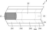
도 4를 참조하면, 궐련(2)은 담배 로드(21) 및 필터 로드(22)를 포함한다. 도 1 내지 도 3을 참조하여 상술한 제 1 부분(21)은 담배 로드(21)를 포함하고, 제 2 부분(22)은 필터 로드(22)를 포함한다.Referring to Figure 4, the
도 4에는 필터 로드(22)가 단일 세그먼트로 도시되어 있으나, 이에 한정되지 않는다. 다시 말해, 필터 로드(22)는 복수의 세그먼트들로 구성될 수도 있다. 예를 들어, 필터 로드(22)는 에어로졸을 냉각하는 세그먼트 및 에어로졸 내에 포함된 소정의 성분을 필터링하는 세그먼트를 포함할 수 있다. 또한, 필요에 따라, 필터 로드(22)에는 다른 기능을 수행하는 적어도 하나의 세그먼트를 더 포함할 수 있다.In Figure 4, the
궐련(2)은 적어도 하나의 래퍼(24)에 의하여 포장될 수 있다. 래퍼(24)에는 외부 공기가 유입되거나 내부 기체가 유출되는 적어도 하나의 구멍(hole)이 형성될 수 있다. 일 예로서, 궐련(2)은 하나의 래퍼(24)에 의하여 포장될 수 있다. 다른 예로서, 궐련(2)은 2 이상의 래퍼(24)들에 의하여 중첩적으로 포장될 수도 있다. 예를 들어, 제1 래퍼(241)에 의하여 담배 로드(21)가 포장되고, 래퍼들(242, 243, 244)에 의하여 필터 로드(22)가 포장될 수 있다. 그리고, 단일 래퍼(245)에 의하여 궐련(2) 전체가 재포장될 수 있다. 만약, 필터 로드(22)가 복수의 세그먼트들로 구성되어 있다면, 각각의 세그먼트가 래퍼들(242, 243, 244)에 의하여 포장될 수 있다.The
담배 로드(21)는 에어로졸 생성 물질을 포함한다. 예를 들어, 에어로졸 생성 물질은 글리세린, 프로필렌 글리콜, 에틸렌 글리콜, 디프로필렌 글리콜, 디에틸렌 글리콜, 트리에틸렌 글리콜, 테트라에틸렌 글리콜 및 올레일 알코올 중 적어도 하나를 포함할 수 있으나, 이에 한정되지 않는다. 또한, 담배 로드(21)는 풍미제, 습윤제 및/또는 유기산(organic acid)과 같은 다른 첨가 물질을 함유할 수 있다. 또한, 담배 로드(21)에는, 멘솔 또는 보습제 등의 가향액이, 담배 로드(21)에 분사됨으로써 첨가할 수 있다.The
담배 로드(21)는 다양하게 제작될 수 있다. 예를 들어, 담배 로드(21)는 시트(sheet)로 제작될 수도 있고, 가닥(strand)으로 제작될 수도 있다. 또한, 담배 로드(21)는 담배 시트가 잘게 잘린 각초로 제작될 수도 있다. 또한, 담배 로드(21)는 열 전도 물질에 의하여 둘러싸일 수 있다. 예를 들어, 열 전도 물질은 알루미늄 호일과 같은 금속 호일일 수 있으나, 이에 한정되지 않는다. 일 예로, 담배 로드(21)를 둘러싸는 열 전도 물질은 담배 로드(21)에 전달되는 열을 고르게 분산시켜 담배 로드에 가해지는 열 전도율을 향상시킬 수 있으며, 이로 인해 담배 맛을 향상시킬 수 있다. 또한, 담배 로드(21)를 둘러싸는 열 전도 물질은 유도 가열식 히터에 의해 가열되는 서셉터로서의 기능을 할 수 있다. 이때, 도면에 도시되지는 않았으나, 담배 로드(21)는 외부를 둘러싸는 열 전도 물질 이외에도 추가의 서셉터를 더 포함할 수 있다.The
필터 로드(22)는 셀룰로오스 아세테이트 필터일 수 있다. 한편, 필터 로드(22)의 형상에는 제한이 없다. 예를 들어, 필터 로드(22)는 원기둥 형(type) 로드일 수도 있고, 내부에 중공을 포함하는 튜브 형(type) 로드일 수도 있다. 또한, 필터 로드(22)는 리세스 형(type) 로드일 수도 있다. 만약, 필터 로드(22)가 복수의 세그먼트들로 구성된 경우, 복수의 세그먼트들 중 적어도 하나가 다른 형상으로 제작될 수도 있다.
또한, 필터 로드(22)에는 적어도 하나의 캡슐(23)이 포함될 수 있다. 여기에서, 캡슐(23)은 향미를 발생시키는 기능을 수행할 수도 있고, 에어로졸을 발생시키는 기능을 수행할 수도 있다. 예를 들어, 캡슐(23)은 향료를 포함하는 액체를 피막으로 감싼 구조일 수 있다. 캡슐(23)은 구형 또는 원통형의 형상을 가질 수 있으나, 이에 제한되지 않는다.Additionally, the
도 5를 참조하면, 궐련(3)은 전단 플러그(33)를 더 포함할 수 있다. 전단 플러그(33)는 담배 로드(31)에 있어서, 필터 로드(32)에 대향하는 일 측에 위치할 수 있다. 전단 플러그(33)는 담배 로드(31)가 외부로 이탈하는 것을 방지할 수 있으며, 흡연 중에 담배 로드(31)로부터 액상화된 에어로졸이 에어로졸 발생 장치(도 1 내지 도 3의 1)로 흘러 들어가는 것을 방지할 수 있다.Referring to Figure 5, the
필터로드(32)은 제1 세그먼트(321) 및 제2 세그먼트(322)를 포함할 수 있다. 여기에서, 제1 세그먼트(321)은 도 4의 필터 로드(22)의 제1 세그먼트에 대응될 수 있고, 제2 세그먼트(322)는 도 4의 필터 로드(22)의 제3 세그먼트에 대응될 수 있다.The
궐련(3)의 직경 및 전체 길이는 도 4의 궐련(2)의 직경 및 전체 길이에 대응될 수 있다. 예를 들어, 전단 플러그(33)의 길이는 약 7mm, 담배 로드(31)의 길이는 약 15mm, 제1 세그먼트(321)의 길이는 약 12mm, 제2 세그먼트(322)의 길이는 약 14mm일 수 있으나, 이에 한정되지 않는다.The diameter and overall length of the
궐련(3)은 적어도 하나의 래퍼(35)에 의하여 포장될 수 있다. 래퍼(35)에는 외부 공기가 유입되거나 내부 기체가 유출되는 적어도 하나의 구멍(hole)이 형성될 수 있다. 예를 들어, 제1 래퍼(351)에 의하여 전단 플러그(33)이 포장되고, 제2 래퍼(352)에 의하여 담배 로드(31)가 포장되고, 제3 래퍼(353)에 의하여 제1 세그먼트(321)이 포장되고, 제4 래퍼(354)에 의하여 제2 세그먼트(322)가 포장될 수 있다. 그리고, 제5 래퍼(355)에 의하여 궐련(3) 전체가 재포장될 수 있다.The
또한, 제5 래퍼(355)에는 적어도 하나의 천공(36)이 형성될 수 있다. 예를 들어, 천공(36)은 담배 로드(31)를 둘러싸는 영역에 형성될 수 있으나, 이에 제한되지 않는다. 천공(36)은 도 2 및 도 3에 도시된 히터(13)에 의하여 형성된 열을 담배 로드(31)의 내부로 전달하는 역할을 수행할 수 있다.Additionally, at least one
또한, 제2 세그먼트(322)에는 적어도 하나의 캡슐(34)이 포함될 수 있다. 여기에서, 캡슐(34)은 향미를 발생시키는 기능을 수행할 수도 있고, 에어로졸을 발생시키는 기능을 수행할 수도 있다. 예를 들어, 캡슐(34)은 향료를 포함하는 액체를 피막으로 감싼 구조일 수 있다. 캡슐(34)은 구형 또는 원통형의 형상을 가질 수 있으나, 이에 제한되지 않는다.Additionally, the
도 6은 일 실시 예에 따른 에어로졸 생성 장치의 내부 블록도이다.Figure 6 is an internal block diagram of an aerosol generating device according to an embodiment.
도 6을 참조하면, 에어로졸 생성 장치(100)는 입력부(110), 출력부(120), 감지부(130), 인터페이스부(140), 가열부(150), 배터리(160), 메모리(170) 및 제어부(180)를 포함할 수 있다. 도 6의 에어로졸 생성 장치(100)는 도 1 내지 도 3의 에어로졸 생성 장치(1)에 대응될 수 있다. 또한, 도 6의 배터리(160)는 도 1 내지 도 3의 배터리(11)에 대응되고, 도 6의 제어부(180)는 도 1 내지 도 3의 제어부(12)에 대응될 수 있다.Referring to FIG. 6, the
입력부(110)는 사용자 입력을 수신할 수 있다. 예를 들어, 입력부(110)는 가압식 푸쉬(push) 버튼 형태로 마련될 수 있으나 이에 제한되지 않는다.The
입력부(110)는 사용자 입력을 수신한 경우, 사용자 입력에 대응하는 제어 신호를 제어부(180)에 전송할 수 있다. 제어부(180)는 제어 신호에 기초하여 에어로졸 생성 장치(100)의 내부 구성들을 제어할 수 있다. 예를 들어, 제어부(180)는 제어 신호에 기초하여 가열부(150)를 가열할 수 있다.When receiving a user input, the
출력부(120)는 에어로졸 생성 장치(100)와 관련된 시각 정보 및/또는 촉각 정보를 출력할 수 있다. 이를 위하여 출력부(120)는 디스플레이(미도시), 진동 모터(미도시) 등을 포함할 수 있다.The
감지부(130)는 가열부(150)의 온도를 감지하는 온도 감지부(131) 및 가열부(150)에 공급되는 전류를 감지하는 전류 감지부(132)를 포함할 수 있다. 온도 감지부(131)는 적어도 어느 하나의 온도 센서를 포함하고, 온도 센서는 가열부(150)와 인접하여 배치될 수 있다. 전류 감지부(132)는 적어도 하나의 션트(shunt) 저항을 포함할 수 있으나 이에 제한되지 않는다.The
실시 예에 따라, 감지부(130)는 사용자의 퍼프를 감지하기 위한 퍼프 센서를 더 포함할 수 있다.Depending on the embodiment, the
인터페이스부(140)는 에어로졸 생성 장치(100)에 연결되는 다양한 종류의 외부 디바이스와의 통로 역할을 수행할 수 있다. 예를 들어, 인터페이스부(140)는 외부 디바이스와 연결 가능한 포트(port)를 구비할 수 있고, 에어로졸 생성 장치(100)는 포트를 통해 외부 디바이스와 연결될 수 있다. 에어로졸 생성 장치(100)는 외부 디바이스와 연결된 상태에서, 외부 디바이스와 데이터를 교환할 수 있다.The
인터페이스부(140)는 외부 전원을 공급받는 통로 역할을 수행할 수도 있다. 예를 들어, 인터페이스부(140)는 외부 전원과 연결 가능한 포트를 구비할 수 있고, 에어로졸 생성 장치(100)는 외부 전원과 연결된 상태에서, 외부 전원으로부터 외부 전원을 공급받을 수 있다.The
가열부(150)는 전기 저항성 히터 또는 유도 가열식 히터일 수 있다. 가열부(150)가 전기 저항성 히터인 경우, 가열부(150)는 전기 전도성 트랙을 포함할 수 있다. 가열부(150)는 전기 전도성 트랙에 인가된 전류에 의하여 가열될 수 있다. 가열부(150)가 유도 가열식 히터인 경우, 가열부(150)는 전기 전도성 코일 및 서셉터를 포함할 수 있다. 전기 전도성 코일에 전류가 인가되는 경우, 전기 전도성 코일에서 발생되는 변동 자기장에 의해 서셉터가 가열될 수 있다.The
배터리(160)는 제어부(180)의 제어에 의하여 가열부(150)에게 전력을 공급할 수 있다. 배터리(160)는 리튬 이온 배터리일 수 있으나 이에 제한되지 않는다.The
메모리(170)는 에어로졸 생성 장치(100)의 동작을 위한 정보를 저장할 수 있다. 일 실시 예에서, 메모리(170)는 온도 프로파일 및 온도 피드백 제어 구간이 시작되는 기준 온도에 대한 정보를 저장할 수 있다.The
제어부(180)는 배터리(160)가 가열부(150)에 공급하는 전류 펄스의 주파수 및 듀티 사이클(duty cycle) 중 적어도 어느 하나를 조정함으로써, 가열부(150)에 공급되는 전력을 제어할 수 있다. 예를 들어, 제어부(180)는 펄스 폭 변조(pulse width modulation)를 통해 전류 펄스의 주파수 및 듀티 사이클을 증가시켜 가열부(150)에 공급되는 전력을 증가시킬 수 있다.The
제어부(180)는 가열부(150)의 온도에 대한 제어의 목표가 되는 목표 온도를 설정할 수 있다. 예를 들어, 목표 온도는 335도일 수 있다. 또한, 제어부(180)는 가열부(150)의 온도 및 목표 온도의 차이 값에 기초하여 가열부(150)의 온도를 제어할 수 있다. 다시 말해, 제어부(180)는 가열부(150)의 온도 정보에 기초하여 피드백 제어를 수행할 수 있다.The
구체적으로, 제어부(180)는 가열부(150)의 온도 및 목표 온도의 차이 값, 차이 값을 시간의 흐름에 따라 적분한 값 및 차이 값을 시간의 흐름에 따라 미분한 값을 통한 피드백 제어 방식에 따라 가열부(150)에 공급되는 전력을 제어할 수 있다.Specifically, the
예를 들어, 제어부(180)는 PID(Proportional-Integral-Derivative) 제어 방식으로 가열부(150)의 온도를 제어할 수 있다. PID 제어의 계수는 가열부(150)의 온도가 최적으로 제어될 수 있도록 실험적으로 미리 설정될 수 있다. 제어부(180)는 설정된 PID 제어의 계수에 따라 가열부(150)의 온도가 목표 온도에 도달하도록 가열부(150)의 온도를 제어할 수 있다.For example, the
한편, 가열 초기부터 PID 제어 방식으로 가열부(150)를 가열하는 경우, 전류의 리플(ripple) 성분으로 인하여 배터리(160)의 과부하가 발생될 수 있다. 또한, 전류의 리플(ripple) 성분은 EMF(ElectroMotive Force) 노이즈로 작용하여, 배터리(160)의 심각한 손상을 야기할 수도 있다.Meanwhile, when heating the
본 개시의 에어로졸 생성 장치(100)는 전술한 문제점들을 해결하기 위하여, PID 제어 방식을 통해서 가열부(150)의 온도를 목표 온도까지 상승시키기 전에, 전류 제한 방식으로 가열부(150)를 가열할 수 있다.In order to solve the above-described problems, the
구체적으로, 제어부(180)는 가열 초기에 가열부(150)에 공급되는 전류의 크기를 제한할 수 있다. 제어부(180)는 가열부(150)에 공급되는 전류의 크기를 기 설정된 기준 전류 이하로 제한할 수 있다. 기준 전류는 1A(ampere) 내지 4A 범위 내에서 설정될 수 있다. 기준 전류의 하한을 1A로 설정하는 이유는, 가열부(150)를 가열하기 위해 요구되는 최소 전류가 1A 이상이기 때문이다. 또한, 기준 전류의 상한을 4A으로 설정하는 이유는, 배터리(160)의 정격 전류가 6A이고, 가열부(150)를 제외한 나머지 구성들의 요구 전류의 합이 2A이기 때문이다. 예를 들어, 기준 전류는 1.95A로 설정될 수 있다.Specifically, the
제어부(180)는 가열부(150)의 온도가 기 설정된 기준 온도에 도달할 때까지 전류 제한 방식으로 가열부(150)를 가열할 수 있다. 기준 온도는 가열부(150)의 오버슈트(overshoot) 제어의 가능 여부에 기초하여 설정될 수 있다. 예를 들어, 기준 온도는 목표 온도의 -200도 내지 -30도 범위 내에서 설정될 수 있다. 예를 들어, 기준 전류가 1.95A인 경우, 기준 온도는 목표 온도의 -35도로 설정될 수 있다.The
한편, 기준 전류가 증가할수록 가열부(150)의 온도 증가 속도가 커질 수 있다. 따라서, 오버슈트를 고려할 때, 기준 전류가 증가할수록, 기준 온도는 더 작아질 수 있다. 예를 들어, 기준 전류가 1.95A 보다 큰 경우, 기준 온도는 목표 온도의 -35도 보다 작아질 수 있다.Meanwhile, as the reference current increases, the temperature increase rate of the
전술한 것처럼, 본 발명에 따른 에어로졸 생성 장치(100)는, 제어부(180)가 가열부(150)의 가열 초기 구간에서 가열부(150)에 공급되는 전류의 크기를 조절함에 따라, 전류의 리플 성분에 의해 유발되는 배터리(160)의 손상이 방지될 수 있으며, 보다 구체적으로, 제어부(180)는 전류의 크기를 기준 전류 이하로 제한하게 된다.As described above, in the
도 7은 일 실시 예에 따른 전류 제한 방법을 설명하기 위한 도면이다.Figure 7 is a diagram for explaining a current limiting method according to an embodiment.
도 7을 참조하면, 전류 감지부(132)는 가열부(150)에 공급되는 전류를 감지할 수 있다. 전류 감지부(132)는 전류 정보를 제어부(180)에 전송할 수 있다.Referring to FIG. 7 , the
제어부(180)는 전류 정보에 기초하여 가열부(150)에 공급되는 전류의 크기를 제한할 수 있다.The
도 7에서와 같이, 본 개시의 에어로졸 생성 장치(100)는 별도의 전류 제한 회로 없이도 제어부(180)의 제어에 따라 가열부(150)에 공급되는 전류의 크기를 제한할 수 있다.As shown in FIG. 7 , the
도 8은 일 실시 예에 따른 예열 방법을 설명하기 위한 도면이다.Figure 8 is a diagram for explaining a preheating method according to an embodiment.
도 8에는 가열부(150)의 온도 그래프(820) 및 전류의 크기 그래프(810)가 도시되어 있다. 도 8을 참조하면, 제어부(180)는 예열 구간 및 흡연 구간에서 가열부(150)에 공급되는 전력을 제어할 수 있다.Figure 8 shows a
예열 구간은 가열부(150)의 온도가 에어로졸이 생성되는 목표 온도(Tt)까지 가열되는 구간을 의미할 수 있다. 가열부(150)가 유도 가열식 히터인 경우, 가열부(150)의 온도는 에어로졸 생성 기질과 직접 접촉하는 서셉터의 온도를 의미할 수 있다. 흡연 구간은 가열부(150)의 온도가 목표 온도(Tt)로 유지되는 구간을 의미할 수 있다.The preheating section may refer to a section in which the temperature of the
목표 온도(Tt)는 에어로졸 생성 기질의 종류에 따라 상이하게 설정될 수 있다. 예를 들어, 목표 온도(Tt)는 335도로 설정될 수 있다.The target temperature (Tt) may be set differently depending on the type of aerosol generating substrate. For example, the target temperature (Tt) may be set to 335 degrees.
제어부(180)는 예열 구간에서 가열부(150)의 온도가 단시간 내에 목표 온도(Tt)까지 도달하도록 가열부(150)에 공급되는 전력을 제어할 수 있다.The
제어부(180)는 전류 제한 구간에서 가열부(150)에 공급되는 전류의 크기를 기 설정된 기준 전류(irs) 이하로 제한할 수 있다. 기준 전류(irs)는 1A 내지 4A 범위 내에서 설정될 수 있다. 예를 들어, 기준 전류(irs)는 1.95A로 설정될 수 있다.The
제어부(180)는 가열부(150)에 공급되는 전류의 크기를 제한한 상태에서, 온도 감지부(131)로부터 가열부(150)의 온도 정보를 수신할 수 있다. 제어부(180)는 가열부(150)의 온도가 기 설정된 기준 온도(Tr)에 도달할 때까지 전류 제한 방식으로 가열부(150)를 가열할 수 있다. 기준 온도(Tr)는 가열부(150)의 오버슈트 제어를 고려하여 목표 온도(Tt)의 -200도 내지 -30도 범위 내에서 설정될 수 있다. 예를 들어, 기준 전류(irs)가 1.95A인 경우, 기준 온도(Tr)는 목표 온도(Tt)의 -35도인 300도로 설정될 수 있다.The
제어부(180)는 가열부(150)의 온도가 기준 온도(Tr)에 도달한 경우, 전류 제한 구간에서 온도 피드백 제어 구간으로 전환할 수 있다. 도 8에서는 제어부(180)가 제1 시간(t1)에 전류 제한 구간에서 온도 피드백 제어 구간으로 전환하는 예를 도시한다.When the temperature of the
제어부(180)는 온도 피드백 제어 구간에서, 가열부(150)의 온도 및 목표 온도(Tt)의 차이 값에 기초하여 피드백 제어를 수행할 수 있다. 제어부(180)는 PID 제어 방식으로 가열부(150)의 온도를 제어할 수 있다. 제어부(180)는 설정된 PID 제어의 계수에 따라 가열부(150)의 온도가 목표 온도에 도달하도록 가열부(150)의 온도를 제어할 수 있다.The
한편, 전류 제한 구간을 제1 예열 구간, 온도 피드백 구간을 제2 예열 구간으로 명명할 수도 있다.Meanwhile, the current limitation section may be referred to as a first preheating section, and the temperature feedback section may be referred to as a second preheating section.
한편, 제어부(180)는 기설정된 예열 구간이 종료된 경우, 흡연 구간으로 전환하여, 가열부(150)의 온도를 목표 온도(Tt)로 유지시킬 수 있다. 도 8에서는 제어부(180)가 제2 시간(t2)에 예열 구간에서 흡연 구간으로 전환하는 예를 도시한다.Meanwhile, when the preset preheating section ends, the
도 9는 일 실시 예에 따른 에어로졸 생성 장치의 동작 방법을 설명하기 위한 흐름도이다.Figure 9 is a flowchart for explaining a method of operating an aerosol generating device according to an embodiment.
도 9를 참조하면, 제어부(180)는 가열부(150)에 공급되는 전류의 크기를 기 설정된 기준 전류 이하로 제한할 수 있다(S910). 기준 전류는 1A 내지 4A 범위 내에서 설정될 수 있다. 예를 들어, 기준 전류는 1.95A로 설정될 수 있다.Referring to FIG. 9, the
제어부(180)는 가열부(150)의 온도와 기준 온도를 비교할 수 있다(S920). 제어부(180)는 가열부(150)의 온도가 기준 온도 미만인 경우, 전류 제한 방식을 유지할 수 있다.The
제어부(180)는 가열부(150)의 온도가 기준 온도 이상인 경우, 가열부(150)의 온도 및 목표 온도의 차이 값에 기초하여 피드백 제어를 수행할 수 있다(S930). 제어부(180)는 설정된 PID 제어의 계수에 따라 가열부(150)의 온도가 목표 온도에 도달하도록 가열부(150)의 온도를 제어할 수 있다.When the temperature of the
도 10은 다른 일 실시 예에 따른 에어로졸 생성 장치의 동작 방법을 설명하기 위한 흐름도이다.Figure 10 is a flowchart for explaining a method of operating an aerosol generating device according to another embodiment.
도 10은 전술한 도 9의 흐름도에서 파생될 수 있는 실시 예를 구체적으로 설명하기 위한 도면으로서, 이하에서는, 도 9에서 이미 설명한 내용과 중복되는 설명은 생략하기로 한다.FIG. 10 is a diagram for specifically explaining an embodiment that can be derived from the flowchart of FIG. 9 described above. Hereinafter, descriptions that overlap with the content already described in FIG. 9 will be omitted.
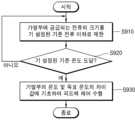
먼저, 제어부(180)은 에어로졸 생성 장치(100)의 전원이 켜지면, 가열부(150)에 공급되는 전류의 크기를 최소전류이상 기준 전류 이하의 범위에서 선택한다(S1010). 여기서, 최소전류는 가열부(150)의 온도를 일정속도 이상으로 상승시키기 위해 필요한 최소한의 전류로서, 전술한 기준 전류의 하한값인 1A가 될 수 있다. 또한, 단계 S1010에서 기준 전류는, 4A가 될 수 있다.First, when the
단계 S1010에서 제어부(180)는 가열부(150)에 공급되는 전류의 크기가 4A를 넘지 않도록 제어함으로써, 전류의 리플 성분을 최소화하고 배터리의 손상을 방지하며, 동시에, 가열부(150)에 공급되는 전류의 크기가 최소 1A이상은 되도록 제어함으로써, 가열부(150)에 대한 일정 이상의 예열속도가 확보될 수 있다. 제어부(180)는 경험적 또는 실험적으로 결정된 정보를 참고하여, 가열부(150)에 공급되는 전류의 크기를 최소전류이상 기준 전류 이하의 범위에서 적절하게 선택할 수 있고, 앞서, 기준 전류는 1.95A가 될 수 있다고 설명한 바 있다.In step S1010, the
이어서, 제어부(180)는 단계 S1030에서 선택된 기준 전류를 기초로 기준 온도를 설정한다(S1030). 앞서, 도 6 및 도 8에 대한 설명에서, 기준 온도는 가열부(150)의 목표 온도보다 200도 더 낮은 온도 내지 목표 온도보다 30도 더 낮은 온도에서 선택된 온도값이 될 수 있다고 하였으며, 예를 들어, 가열부(150)의 목표 온도가 335도라면, 가열부(150)의 기준 온도는 135도와 305도 사이에서 선택된 값이 될 수 있다. 이때, 제어부(180)가 135도와 305도 사이에서 기준 온도를 선택할 때에 기준이 되는 지표 중에 하나는 기준 전류의 크기이며, 특히, 기준 전류의 크기가 커질수록 제어부(180)에 의해 선택되는 기준 온도의 크기는 더 작아진다. 단계 S1030에서, 기준 전류의 크기와 기준 온도의 크기와의 관계를 수학식으로 정리하면 수학식 1과 같다.Next, the
수학식 1은 제어부(180)에 의해 선택되는 기준 온도의 크기와 기준 전류의 크기와의 상관관계를 수학식으로 나타낸다. 수학식 1에서, Tr은 기준 온도의 크기, irs는 기준 전류의 크기, k는 비례상수를 각각 의미하고, 수학식 1은 기준 전류의 크기가 더 커질수록 기준 온도의 크기는 더 작아지는 반비례관계가 있음을 나타낸다. 수학식 1과 같은 기준 온도와 기준 전류간의 관계성은 가열부(150)의 목표 온도보다 더 높게 가열되는 현상인 오버슈트(overshoot)이 발생되지 않도록 제어부(180)가 제어하는 과정에서 성립되며, 본 발명에서 가열부(150)의 오버슈트이 방지됨에 따라, 매질(에어로졸 생성기질)의 탄화현상으로 인해서 에어로졸 생성 장치(100)를 사용하는 사용자가 불쾌한 흡연경험을 하는 경우를 미연에 방지할 수 있게 된다.
이어서, 제어부(180)는 선택된 크기의 전류가 가열부(150)에 공급되도록 제어하여, 가열부(150)의 온도를 단계 S1030에서 설정한 기준온도까지 상승시킨다(S1050).Next, the
제어부(180)는 가열부(150)의 온도가 기설정된 기준온도에 도달했는지 판단한다(S1070). 단계 S1070에서, 가열부(150)의 온도가 기준온도에 도달했다면, 제어부(180)는 가열부(150)의 온도가 목표 온도에 도달할 때까지 PID 방식으로 가열부(150)의 온도가 상승되도록 제어한다(S1090). 단계 S1030 내지 단계 S1070를 거쳐서, 가열부(150)의 온도는 리플 전류(ripple current)를 발생시키지 않을 뿐만 아니라 오버슈트도 생기지 않도록 가열부(150)의 최초온도부터 목표 온도까지 단조적으로(monotonically) 상승되며, 본 발명에 따른 에어로졸 생성 장치(100)는 배터리의 손상을 방지하여 장치의 안정성을 증대시키면서, 장치를 사용하는 사용자의 만족스러운 흡연감을 보장할 수 있다.The
본 개시의 에어로졸 생성 장치(100)는 예열 초기 구간에서 PID 제어 방식이 아닌 전류 제한 방식에 따라 가열부(150)에 공급되는 전력을 제어함에 따라, 전류의 리플 성분이 감소된다. 따라서, 배터리(160)의 과부하 및 EMF 노이즈에 의한 배터리(160)의 손상이 방지된다.The
이상 설명된 본 발명에 따른 실시 예는 컴퓨터상에서 다양한 구성요소를 통하여 실행될 수 있는 컴퓨터 프로그램의 형태로 구현될 수 있으며, 이와 같은 컴퓨터 프로그램은 컴퓨터로 판독 가능한 매체에 기록될 수 있다. 이때, 매체는 하드 디스크, 플로피 디스크 및 자기 테이프와 같은 자기 매체, CD-ROM 및 DVD와 같은 광기록 매체, 플롭티컬 디스크(floptical disk)와 같은 자기-광 매체(magneto-optical medium), 및 ROM, RAM, 플래시 메모리 등과 같은, 프로그램 명령어를 저장하고 실행하도록 특별히 구성된 하드웨어 장치를 포함할 수 있다.Embodiments according to the present invention described above may be implemented in the form of a computer program that can be executed through various components on a computer, and such a computer program may be recorded on a computer-readable medium. At this time, the media includes magnetic media such as hard disks, floppy disks, and magnetic tapes, optical recording media such as CD-ROMs and DVDs, magneto-optical media such as floptical disks, and ROM. , RAM, flash memory, etc., may include hardware devices specifically configured to store and execute program instructions.
한편, 상기 컴퓨터 프로그램은 본 발명을 위하여 특별히 설계되고 구성된 것이거나 컴퓨터 소프트웨어 분야의 당업자에게 공지되어 사용 가능한 것일 수 있다. 컴퓨터 프로그램의 예에는, 컴파일러에 의하여 만들어지는 것과 같은 기계어 코드뿐만 아니라 인터프리터 등을 사용하여 컴퓨터에 의해서 실행될 수 있는 고급 언어 코드도 포함될 수 있다.Meanwhile, the computer program may be designed and configured specifically for the present invention, or may be known and available to those skilled in the art of computer software. Examples of computer programs may include not only machine language code such as that created by a compiler, but also high-level language code that can be executed by a computer using an interpreter or the like.
본 발명에서 설명하는 특정 실행들은 일 실시 예들로서, 어떠한 방법으로도 본 발명의 범위를 한정하는 것은 아니다. 명세서의 간결함을 위하여, 종래 전자적인 구성들, 제어 시스템들, 소프트웨어, 상기 시스템들의 다른 기능적인 측면들의 기재는 생략될 수 있다. 또한, 도면에 도시된 구성 요소들 간의 선들의 연결 또는 연결 부재들은 기능적인 연결 및/또는 물리적 또는 회로적 연결들을 예시적으로 나타낸 것으로서, 실제 장치에서는 대체 가능하거나 추가의 다양한 기능적인 연결, 물리적인 연결, 또는 회로 연결들로서 나타내어질 수 있다. 또한, “필수적인”, “중요하게” 등과 같이 구체적인 언급이 없다면 본 발명의 적용을 위하여 반드시 필요한 구성 요소가 아닐 수 있다.The specific implementations described in the present invention are examples and do not limit the scope of the present invention in any way. For the sake of brevity of the specification, descriptions of conventional electronic components, control systems, software, and other functional aspects of the systems may be omitted. In addition, the connections or connection members of lines between components shown in the drawings exemplify functional connections and/or physical or circuit connections, and in actual devices, various functional connections or physical connections may be replaced or added. Can be represented as connections, or circuit connections. Additionally, if there is no specific mention such as “essential,” “important,” etc., it may not be a necessary component for the application of the present invention.
본 발명의 명세서(특히 특허청구범위에서)에서 “상기”의 용어 및 이와 유사한 지시 용어의 사용은 단수 및 복수 모두에 해당하는 것일 수 있다. 또한, 본 발명에서 범위(range)를 기재한 경우 상기 범위에 속하는 개별적인 값을 적용한 발명을 포함하는 것으로서(이에 반하는 기재가 없다면), 발명의 상세한 설명에 상기 범위를 구성하는 각 개별적인 값을 기재한 것과 같다. 마지막으로, 본 발명에 따른 방법을 구성하는 단계들에 대하여 명백하게 순서를 기재하거나 반하는 기재가 없다면, 상기 단계들은 적당한 순서로 행해질 수 있다. 반드시 상기 단계들의 기재 순서에 따라 본 발명이 한정되는 것은 아니다. 본 발명에서 모든 예들 또는 예시적인 용어(예들 들어, 등등)의 사용은 단순히 본 발명을 상세히 설명하기 위한 것으로서 특허청구범위에 의해 한정되지 않는 이상 상기 예들 또는 예시적인 용어로 인해 본 발명의 범위가 한정되는 것은 아니다. 또한, 당업자는 다양한 수정, 조합 및 변경이 부가된 특허청구범위 또는 그 균등물의 범주 내에서 설계 조건 및 팩터에 따라 구성될 수 있음을 알 수 있다.In the specification of the present invention (especially in the claims), the use of the term “above” and similar referential terms may refer to both the singular and the plural. In addition, when a range is described in the present invention, the invention includes the application of individual values within the range (unless there is a statement to the contrary), and each individual value constituting the range is described in the detailed description of the invention. It's the same. Finally, unless there is an explicit order or statement to the contrary regarding the steps constituting the method according to the invention, the steps may be performed in any suitable order. The present invention is not necessarily limited by the order of description of the above steps. The use of any examples or illustrative terms (e.g., etc.) in the present invention is merely to describe the present invention in detail, and unless limited by the claims, the scope of the present invention is limited by the examples or illustrative terms. It doesn't work. Additionally, those skilled in the art will recognize that various modifications, combinations and changes may be made depending on design conditions and factors within the scope of the appended claims or their equivalents.
1, 100: 에어로졸 생성 장치
150: 가열부
170: 배터리
190: 제어부1, 100: Aerosol generating device
150: heating unit
170: battery
190: Control unit
Claims (15)
Translated fromKorean에어로졸 생성 기질을 가열하여 에어로졸을 생성시키는 가열부;
상기 에어로졸 생성 장치의 동작에 사용되는 전력을 공급하는 배터리; 및
상기 가열부에 공급되는 전력을 제어하는 제어부를 포함하고,
상기 제어부는,
상기 가열부에 공급되는 전류의 크기를 기 설정된 기준 전류 이하로 조절하여 상기 가열부의 온도가 기설정된 기준 온도까지 상승되도록 제어하고,
상기 가열부의 온도가 상기 기준 온도에 도달하면, 상기 가열부의 온도와 목표 온도의 차이값을 기초로 상기 가열부의 온도가 상기 기준 온도부터 목표 온도까지 상승되도록 제어하고,
상기 기 설정된 기준 전류는 상기 배터리의 정격 전류보다 낮은, 에어로졸 생성 장치.In the aerosol generating device,
A heating unit that heats the aerosol-generating substrate to generate an aerosol;
a battery supplying power used to operate the aerosol generating device; and
It includes a control unit that controls the power supplied to the heating unit,
The control unit,
Controlling the size of the current supplied to the heating unit below a preset reference current so that the temperature of the heating unit rises to the preset reference temperature,
When the temperature of the heating unit reaches the reference temperature, the temperature of the heating unit is controlled to rise from the reference temperature to the target temperature based on the difference between the temperature of the heating unit and the target temperature,
The preset reference current is lower than the rated current of the battery.
상기 기준 전류의 값은 4암페어(ampere)인, 에어로졸 생성 장치.According to paragraph 1,
An aerosol generating device wherein the value of the reference current is 4 ampere.
상기 제어부는,
상기 가열부의 온도를 일정속도 이상으로 상승시키기 위한 최소전류 이상으로 제어하는, 에어로졸 생성 장치.According to paragraph 1,
The control unit,
An aerosol generating device that controls the temperature of the heating unit to be higher than the minimum current for raising the temperature to a certain speed or higher.
상기 최소전류의 값은 1암페어(ampere)인, 에어로졸 생성 장치.According to paragraph 4,
An aerosol generating device wherein the value of the minimum current is 1 ampere.
상기 제어부는,
상기 가열부에 공급되는 전류의 크기를 기설정된 범위에서 선택된 값으로 조절하는, 에어로졸 생성 장치.According to paragraph 1,
The control unit,
An aerosol generating device that adjusts the magnitude of the current supplied to the heating unit to a value selected from a preset range.
상기 제어부는,
상기 가열부에 공급되는 전류의 크기를 1암페어 내지 4암페어에서 선택된 값으로 조절하는, 에어로졸 생성 장치.According to clause 6,
The control unit,
An aerosol generating device that adjusts the magnitude of the current supplied to the heating unit to a value selected from 1 Ampere to 4 Ampere.
상기 기준 온도는,
상기 가열부의 목표 온도보다 200도 더 낮은 제1온도 내지 상기 목표 온도보다 30도 더 낮은 제2온도에서 선택된 값인, 에어로졸 생성 장치.According to paragraph 1,
The reference temperature is,
The aerosol generating device is a value selected from a first temperature 200 degrees lower than the target temperature of the heating unit and a second temperature 30 degrees lower than the target temperature.
상기 기준 온도는,
상기 기준 전류의 크기를 기초로 변경되는, 에어로졸 생성 장치.According to paragraph 1,
The reference temperature is,
An aerosol generating device that changes based on the magnitude of the reference current.
상기 기준 온도의 크기는,
상기 기준 전류의 크기가 커질수록 더 작아지는, 에어로졸 생성 장치.According to clause 9,
The magnitude of the reference temperature is,
An aerosol generating device that becomes smaller as the magnitude of the reference current increases.
상기 제어부는,
상기 가열부의 온도가 상기 기준 온도에 도달하면, 비례적분미분(proportional-integrate-derivative)방식으로 상기 가열부의 온도가 상기 목표 온도까지 상승되도록 제어하는, 에어로졸 생성 장치.According to paragraph 1,
The control unit,
An aerosol generating device that controls the temperature of the heating unit to rise to the target temperature using a proportional-integrate-derivative method when the temperature of the heating unit reaches the reference temperature.
상기 제어부는,
상기 가열부가 가열되기 시작하고 상기 기준 온도를 거쳐서 상기 목표 온도에 도달할 때까지, 상기 가열부의 온도가 단조적으로(monotonically) 상승되도록 제어하는, 에어로졸 생성 장치.According to paragraph 1,
The control unit,
An aerosol generating device that controls the temperature of the heating unit to rise monotonically from the time the heating unit begins to heat through the reference temperature until it reaches the target temperature.
전원이 켜지면, 상기 가열부에 공급되는 전류의 크기를 기 설정된 기준 전류 이하로 조절하는 단계;
상기 가열부의 온도가 기설정된 기준 온도에 도달하는지 여부를 판단하는 단계; 및
상기 가열부의 온도가 상기 기준 온도에 도달하면, 상기 가열부의 온도와 목표 온도의 차이값을 기초로 상기 가열부의 온도가 상기 기준 온도부터 목표 온도까지 상승되도록 제어하는 단계;를 포함하고,
상기 기 설정된 기준 전류는 배터리의 정격 전류보다 낮은, 에어로졸 생성 장치의 가열부에 공급되는 전력을 제어하는 방법.As a method of controlling the power supplied to the heating unit of the aerosol generating device,
When the power is turned on, adjusting the amount of current supplied to the heating unit below a preset reference current;
determining whether the temperature of the heating unit reaches a preset reference temperature; and
When the temperature of the heating unit reaches the reference temperature, controlling the temperature of the heating unit to rise from the reference temperature to the target temperature based on the difference between the temperature of the heating unit and the target temperature,
A method for controlling the power supplied to the heating unit of the aerosol generating device, wherein the preset reference current is lower than the rated current of the battery.
A computer-readable recording medium storing a program for executing the method according to claim 13.
Priority Applications (5)
| Application Number | Priority Date | Filing Date | Title |
|---|---|---|---|
| PCT/KR2021/012102WO2022050813A1 (en) | 2020-09-07 | 2021-09-07 | Aerosol generating device |
| CN202180004619.8ACN114502020B (en) | 2020-09-07 | 2021-09-07 | Aerosol generating device, method of controlling the same, and computer-readable recording medium |
| JP2022502380AJP7324360B2 (en) | 2020-09-07 | 2021-09-07 | aerosol generator |
| US17/596,452US20230148679A1 (en) | 2020-09-07 | 2021-09-07 | Aerosol generating device |
| EP21820441.0AEP3989755A4 (en) | 2020-09-07 | 2021-09-07 | Aerosol generating device |
Applications Claiming Priority (2)
| Application Number | Priority Date | Filing Date | Title |
|---|---|---|---|
| KR20200113743 | 2020-09-07 | ||
| KR1020200113743 | 2020-09-07 |
Publications (2)
| Publication Number | Publication Date |
|---|---|
| KR20220032464A KR20220032464A (en) | 2022-03-15 |
| KR102621759B1true KR102621759B1 (en) | 2024-01-09 |
Family
ID=80817103
Family Applications (1)
| Application Number | Title | Priority Date | Filing Date |
|---|---|---|---|
| KR1020210064734AActiveKR102621759B1 (en) | 2020-09-07 | 2021-05-20 | Aerosol generating device |
Country Status (1)
| Country | Link |
|---|---|
| KR (1) | KR102621759B1 (en) |
Citations (1)
| Publication number | Priority date | Publication date | Assignee | Title |
|---|---|---|---|---|
| WO2020017789A1 (en)* | 2018-07-18 | 2020-01-23 | 주식회사 케이티앤지 | Method for controlling temperature of heater of aerosol generation device for each interval and aerosol generation device for implementing same method |
- 2021
- 2021-05-20KRKR1020210064734Apatent/KR102621759B1/enactiveActive
Patent Citations (1)
| Publication number | Priority date | Publication date | Assignee | Title |
|---|---|---|---|---|
| WO2020017789A1 (en)* | 2018-07-18 | 2020-01-23 | 주식회사 케이티앤지 | Method for controlling temperature of heater of aerosol generation device for each interval and aerosol generation device for implementing same method |
Also Published As
| Publication number | Publication date |
|---|---|
| KR20220032464A (en) | 2022-03-15 |
Similar Documents
| Publication | Publication Date | Title |
|---|---|---|
| CN111629618B (en) | Aerosol generating device and control method thereof | |
| KR102116118B1 (en) | Method for controlling temperature of heater of aerosol generator and apparatus thereof | |
| KR102131278B1 (en) | Method for controlling overshoot of heater of aerosol generator and apparatus thereof | |
| KR102194731B1 (en) | Aerosol generating device that supplies power to two heaters with one battery | |
| KR102146055B1 (en) | Method for preventing overshoot of heater of aerosol generator and apparatus thereof | |
| KR102105548B1 (en) | Method for executing feedback control of aerosol generating apparatus and method thereof | |
| CN112188839B (en) | Aerosol generating device, power control method therefor, and computer-readable recording medium | |
| KR102330809B1 (en) | Aerosol generating device and preheating method thereof | |
| CN113507857B (en) | Aerosol generating device, method of controlling the same, and computer-readable recording medium | |
| KR102271274B1 (en) | Aerosol generating device and method for controlling same | |
| JP7640032B2 (en) | Aerosol Generator | |
| JP2022119991A (en) | METHOD FOR CONTROLLING POWER OF HEATER OF AEROSOL GENERATOR WITH SIGNAL UNDER CONSTANT FREQUENCY AND AEROSOL GENERATOR THEREOF | |
| KR102253051B1 (en) | Aerosol generating system | |
| JP7324360B2 (en) | aerosol generator | |
| KR20220003885A (en) | Aerosol generating device and operation method thereof | |
| KR102621759B1 (en) | Aerosol generating device |
Legal Events
| Date | Code | Title | Description |
|---|---|---|---|
| PA0109 | Patent application | Patent event code:PA01091R01D Comment text:Patent Application Patent event date:20210520 | |
| PA0201 | Request for examination | ||
| PG1501 | Laying open of application | ||
| E902 | Notification of reason for refusal | ||
| PE0902 | Notice of grounds for rejection | Comment text:Notification of reason for refusal Patent event date:20230702 Patent event code:PE09021S01D | |
| E701 | Decision to grant or registration of patent right | ||
| PE0701 | Decision of registration | Patent event code:PE07011S01D Comment text:Decision to Grant Registration Patent event date:20231004 | |
| GRNT | Written decision to grant | ||
| PR0701 | Registration of establishment | Comment text:Registration of Establishment Patent event date:20240102 Patent event code:PR07011E01D | |
| PR1002 | Payment of registration fee | Payment date:20240103 End annual number:3 Start annual number:1 | |
| PG1601 | Publication of registration |