KR102613788B1 - Steering Apparatus for Vehicle - Google Patents
Steering Apparatus for VehicleDownload PDFInfo
- Publication number
- KR102613788B1 KR102613788B1KR1020160139115AKR20160139115AKR102613788B1KR 102613788 B1KR102613788 B1KR 102613788B1KR 1020160139115 AKR1020160139115 AKR 1020160139115AKR 20160139115 AKR20160139115 AKR 20160139115AKR 102613788 B1KR102613788 B1KR 102613788B1
- Authority
- KR
- South Korea
- Prior art keywords
- steering
- shaft
- input
- sensor
- output shaft
- Prior art date
- Legal status (The legal status is an assumption and is not a legal conclusion. Google has not performed a legal analysis and makes no representation as to the accuracy of the status listed.)
- Active
Links
Images


Classifications
- B—PERFORMING OPERATIONS; TRANSPORTING
- B62—LAND VEHICLES FOR TRAVELLING OTHERWISE THAN ON RAILS
- B62D—MOTOR VEHICLES; TRAILERS
- B62D5/00—Power-assisted or power-driven steering
- B62D5/04—Power-assisted or power-driven steering electrical, e.g. using an electric servo-motor connected to, or forming part of, the steering gear
- B—PERFORMING OPERATIONS; TRANSPORTING
- B62—LAND VEHICLES FOR TRAVELLING OTHERWISE THAN ON RAILS
- B62D—MOTOR VEHICLES; TRAILERS
- B62D5/00—Power-assisted or power-driven steering
- B62D5/06—Power-assisted or power-driven steering fluid, i.e. using a pressurised fluid for most or all the force required for steering a vehicle
- B62D5/09—Power-assisted or power-driven steering fluid, i.e. using a pressurised fluid for most or all the force required for steering a vehicle characterised by means for actuating valves
- B62D5/091—Hydraulic steer-by-wire systems, e.g. the valve being actuated by an electric motor
- B—PERFORMING OPERATIONS; TRANSPORTING
- B62—LAND VEHICLES FOR TRAVELLING OTHERWISE THAN ON RAILS
- B62D—MOTOR VEHICLES; TRAILERS
- B62D5/00—Power-assisted or power-driven steering
- B62D5/06—Power-assisted or power-driven steering fluid, i.e. using a pressurised fluid for most or all the force required for steering a vehicle
- B62D5/30—Safety devices, e.g. alternate emergency power supply or transmission means to ensure steering upon failure of the primary steering means
- B—PERFORMING OPERATIONS; TRANSPORTING
- B60—VEHICLES IN GENERAL
- B60W—CONJOINT CONTROL OF VEHICLE SUB-UNITS OF DIFFERENT TYPE OR DIFFERENT FUNCTION; CONTROL SYSTEMS SPECIALLY ADAPTED FOR HYBRID VEHICLES; ROAD VEHICLE DRIVE CONTROL SYSTEMS FOR PURPOSES NOT RELATED TO THE CONTROL OF A PARTICULAR SUB-UNIT
- B60W20/00—Control systems specially adapted for hybrid vehicles
- B—PERFORMING OPERATIONS; TRANSPORTING
- B62—LAND VEHICLES FOR TRAVELLING OTHERWISE THAN ON RAILS
- B62D—MOTOR VEHICLES; TRAILERS
- B62D15/00—Steering not otherwise provided for
- B62D15/02—Steering position indicators ; Steering position determination; Steering aids
- B62D15/025—Active steering aids, e.g. helping the driver by actively influencing the steering system after environment evaluation
- B—PERFORMING OPERATIONS; TRANSPORTING
- B62—LAND VEHICLES FOR TRAVELLING OTHERWISE THAN ON RAILS
- B62D—MOTOR VEHICLES; TRAILERS
- B62D5/00—Power-assisted or power-driven steering
- B62D5/04—Power-assisted or power-driven steering electrical, e.g. using an electric servo-motor connected to, or forming part of, the steering gear
- B62D5/0409—Electric motor acting on the steering column
- B62D5/0412—Electric motor acting on the steering column the axes of motor and steering column being parallel
- B—PERFORMING OPERATIONS; TRANSPORTING
- B62—LAND VEHICLES FOR TRAVELLING OTHERWISE THAN ON RAILS
- B62D—MOTOR VEHICLES; TRAILERS
- B62D5/00—Power-assisted or power-driven steering
- B62D5/04—Power-assisted or power-driven steering electrical, e.g. using an electric servo-motor connected to, or forming part of, the steering gear
- B62D5/0442—Conversion of rotational into longitudinal movement
- B62D5/0454—Worm gears
- B—PERFORMING OPERATIONS; TRANSPORTING
- B62—LAND VEHICLES FOR TRAVELLING OTHERWISE THAN ON RAILS
- B62D—MOTOR VEHICLES; TRAILERS
- B62D5/00—Power-assisted or power-driven steering
- B62D5/04—Power-assisted or power-driven steering electrical, e.g. using an electric servo-motor connected to, or forming part of, the steering gear
- B62D5/0457—Power-assisted or power-driven steering electrical, e.g. using an electric servo-motor connected to, or forming part of, the steering gear characterised by control features of the drive means as such
- B62D5/046—Controlling the motor
- B62D5/0463—Controlling the motor calculating assisting torque from the motor based on driver input
- B—PERFORMING OPERATIONS; TRANSPORTING
- B62—LAND VEHICLES FOR TRAVELLING OTHERWISE THAN ON RAILS
- B62D—MOTOR VEHICLES; TRAILERS
- B62D5/00—Power-assisted or power-driven steering
- B62D5/06—Power-assisted or power-driven steering fluid, i.e. using a pressurised fluid for most or all the force required for steering a vehicle
- B—PERFORMING OPERATIONS; TRANSPORTING
- B62—LAND VEHICLES FOR TRAVELLING OTHERWISE THAN ON RAILS
- B62D—MOTOR VEHICLES; TRAILERS
- B62D6/00—Arrangements for automatically controlling steering depending on driving conditions sensed and responded to, e.g. control circuits
- B—PERFORMING OPERATIONS; TRANSPORTING
- B60—VEHICLES IN GENERAL
- B60W—CONJOINT CONTROL OF VEHICLE SUB-UNITS OF DIFFERENT TYPE OR DIFFERENT FUNCTION; CONTROL SYSTEMS SPECIALLY ADAPTED FOR HYBRID VEHICLES; ROAD VEHICLE DRIVE CONTROL SYSTEMS FOR PURPOSES NOT RELATED TO THE CONTROL OF A PARTICULAR SUB-UNIT
- B60W2510/00—Input parameters relating to a particular sub-units
- B60W2510/20—Steering systems
- B60W2510/202—Steering torque
- B—PERFORMING OPERATIONS; TRANSPORTING
- B60—VEHICLES IN GENERAL
- B60W—CONJOINT CONTROL OF VEHICLE SUB-UNITS OF DIFFERENT TYPE OR DIFFERENT FUNCTION; CONTROL SYSTEMS SPECIALLY ADAPTED FOR HYBRID VEHICLES; ROAD VEHICLE DRIVE CONTROL SYSTEMS FOR PURPOSES NOT RELATED TO THE CONTROL OF A PARTICULAR SUB-UNIT
- B60W2520/00—Input parameters relating to overall vehicle dynamics
- B60W2520/10—Longitudinal speed
- B—PERFORMING OPERATIONS; TRANSPORTING
- B60—VEHICLES IN GENERAL
- B60W—CONJOINT CONTROL OF VEHICLE SUB-UNITS OF DIFFERENT TYPE OR DIFFERENT FUNCTION; CONTROL SYSTEMS SPECIALLY ADAPTED FOR HYBRID VEHICLES; ROAD VEHICLE DRIVE CONTROL SYSTEMS FOR PURPOSES NOT RELATED TO THE CONTROL OF A PARTICULAR SUB-UNIT
- B60W2554/00—Input parameters relating to objects
- B60W2554/80—Spatial relation or speed relative to objects
Landscapes
- Engineering & Computer Science (AREA)
- Transportation (AREA)
- Mechanical Engineering (AREA)
- Chemical & Material Sciences (AREA)
- Combustion & Propulsion (AREA)
- Automation & Control Theory (AREA)
- Steering Control In Accordance With Driving Conditions (AREA)
- Power Steering Mechanism (AREA)
Abstract
Translated fromKorean
Description
Translated fromKorean본 발명은 자동차 조향장치에 관한 것으로, 보다 상세하게는 운전자가 직접 조향하지 않아도 유압식 조향동력기의 입력축을 회전시키는 전기식 조향동력기가 구비됨에 따라 승용차에 비하여 상대적으로 큰 조향력이 필요한 트럭이나 버스의 경우에도 운전자의 조향의지와 무관하게 자동차를 제어하는 자동 주차, 차선유지, 트레일러 백업 보조, 노면상태에 따른 주행보조. 조향진동 감쇠, 자율주행제어 등의 부가기능을 사용할 수 있어 운전자의 편의성을 높이는 자동차 조향장치에 관한 것이다.The present invention relates to an automobile steering device, and more specifically, because an electric steering engine is provided that rotates the input shaft of a hydraulic steering engine without the driver directly steering, even in the case of trucks or buses that require a relatively large steering force compared to passenger cars. Automatic parking that controls the car regardless of the driver's steering intention, lane maintenance, trailer backup assistance, and driving assistance depending on road conditions. This relates to an automobile steering system that improves driver convenience by enabling the use of additional functions such as steering vibration damping and autonomous driving control.
일반적으로 자동차의 조향장치는 자동차의 진행 방향을 운전자의 의지대로 변경할 수 있도록 하기 위한 장치로서 자동차의 앞바퀴가 선회하는 회전 중심을 임의로 변경하여 운전자가 원하는 방향으로 자동차를 진행시킬 수 있도록 보조하는 장치이다.In general, the steering device of a car is a device that allows the driver to change the direction of travel of the car at will. It is a device that assists the driver in moving the car in the desired direction by arbitrarily changing the center of rotation around which the car's front wheels turn. .
한편, 동력 보조 조향장치는 운전자가 자동차의 조향 휠(Steering Wheel)을 조작할 경우에 배력 장치를 이용하여 운전자의 조향 휠 조작력을 보조하여 줌으로써 보다 작은 힘으로 용이하게 차량의 진행 방향을 변경할 수 있도록 하는 장치이다.Meanwhile, the power auxiliary steering device uses a booster device to assist the driver's steering wheel operation force when the driver operates the vehicle's steering wheel, allowing the vehicle's direction to be easily changed with less force. It is a device that
이와 같은 동력 보조 조향장치는 전동식 동력 보조 조향장치(EPS: Electronic Power Steering Apparatus)와 유압식 동력 보조 조향장치(HPS: Hydraulic Power Steering Apparatus)로 크게 구분된다.Such power-assisted steering devices are largely divided into electric power-assisted steering devices (EPS: Electronic Power Steering Apparatus) and hydraulic power-assisted steering devices (HPS: Hydraulic Power Steering Apparatus).
유압식 동력 보조 조향장치는 엔진의 회전축에 연결된 유압펌프가 작동유를 랙바(Rack Bar)와 연결되어 있는 작동 실린더로 공급하면, 작동유를 공급받은 작동 실린더의 피스톤이 움직임으로써 조향 조작력을 보조하게 되어 운전자로 하여금 작은 힘으로 조향 조작을 할 수 있도록 하는 조향장치이다.In a hydraulic power auxiliary steering device, when a hydraulic pump connected to the rotation shaft of the engine supplies hydraulic oil to an operating cylinder connected to a rack bar, the piston of the operating cylinder that receives the hydraulic oil moves to assist the driver's steering operation force. It is a steering device that allows steering operation with little force.
반면, 전동식 동력 보조 조향장치는 유압펌프와 작동 실린더 대신에 모터를 포함하고 있어 모터의 힘으로 조향휠의 조작력을 보조해 주는 조향장치이다.On the other hand, the electric power-assisted steering device is a steering device that includes a motor instead of a hydraulic pump and an operating cylinder, and assists the operating force of the steering wheel with the power of the motor.
도 1은 종래의 전동식 동력 보조 조향장치의 개략도이다.1 is a schematic diagram of a conventional electric power assist steering device.
도 1에서 도시하는 바와 같이 전기식 동력 보조 조향장치는 조향휠(101)부터 양측 바퀴(108)까지 이어지는 조향 계통(100) 및 조향 계통(100)에 조향 보조 동력을 제공하는 보조 동력 기구를 포함하여 구성된다.As shown in FIG. 1, the electric power auxiliary steering device includes a
조향계통(100)은 일측이 조향휠(101)에 연결되어 조향휠(101)과 함께 회전하고 타측은 한 쌍의 유니버설 조인트(103)를 매개로 피니언축(104)에 연결되는 조향축(102)을 포함하여 구성된다. 또한, 피니언축(104)은 랙-피니언 기구부(105)를 통해 랙바에 연결되고 랙바의 양단은 타이로드(106)와 너클암(107)을 통해 차량의 바퀴(108)에 연결된다. 랙-피니언 기구부(105)는 피니언축(104)에 형성되어 있는 피니언 기어(111)와 랙바의 외주면일측에 형성되어 있는 랙 기어(112)가 서로 맞물려서 형성되므로 운전자가 조향휠(101)을 조작하면 조향계통(100)에서 토크가 발생하고 토크에 의해서 랙-피니언 기구부(105)와 타이로드(106)를 통하여 바퀴(108)를 조향하게 된다.The
보조 동력기구는 보조 동력을 발생시키는 모터(130) 및 모터(130)에서 발생한 보조 동력을 조향축(102)에 전달하는 감속기(140)를 포함하여 구성된다.The auxiliary power mechanism includes a
도 2는 종래의 유압식 동력 보조 조향장치를 나타내는 부분 단면도이다.Figure 2 is a partial cross-sectional view showing a conventional hydraulic power assist steering device.
도 2에서 각각 도시하는 바와 같이 종래의 유압식 동력 보조 조향장치(200)는 조향휠(도 1의 101 참조)이 장착되어 있는 조향축의 하단부에 설치되어 조향시 작동유의 유동 방향을 제어하는 피니언 밸브 어셈블리(220)와 피니언 밸브 어셈블리(220)의 작동에 따라 조향 차륜을 조향시키는 타이로드(106)에 작용력을 인가하는 작동 실린더(240)를 포함하여 구성된다.As shown in FIG. 2, the conventional hydraulic power
유압펌프(230)로부터 공급되는 작동유가 압력 호스(235)를 통하여 피니언 밸브 어셈블리(220)에 공급되고, 조향시 조향축의 회전 방향에 따라 작동유를 작동 실린더(240)의 좌,우측 압력실에 선택적으로 공급하면, 랙바가 유압에 의해 좌,우로 슬라이딩되면서 조향 조작력을 보조하여 주고, 피니언 밸브 어셈블리(220)에서 동작을 완료한 작동유는 오일 저장 탱크(233)로 돌아와 다시 흡입 호스(237)를 통해 유압펌프(230)로 공급되는 유압 계통을 갖는다.The hydraulic oil supplied from the
이와 같은 종래의 자동차 조향장치는, 승용차에 비하여 상대적으로 큰 조향력이 필요한 트럭이나 버스의 경우에는 전동식 조향동력기의 출력으로는 원하는 출력값을 낼 수 없어서 고출력 사양의 유압식 조향동력기를 이용하는데, 유압식 조향동력기에는 제어부가 구비되어 있지 않아 제어부를 이용한 자동 주차, 차선유지, 미래의 자동 주행 등의 기능을 사용할 수 없는 문제점이 있었다.Such a conventional automobile steering device, in the case of trucks or buses that require relatively large steering force compared to passenger cars, cannot produce the desired output value with the output of the electric steering engine, so a hydraulic steering engine with high output specifications is used. Since it is not equipped with a control unit, there was a problem in that functions such as automatic parking, lane maintenance, and future automatic driving using the control unit could not be used.
본 발명은 전술한 배경에서 안출된 것으로, 운전자가 직접 조향하지 않아도 유압식 조향동력기의 입력축을 회전시키는 전기식 조향동력기가 구비됨에 따라 승용차에 비하여 상대적으로 큰 조향력이 필요한 트럭이나 버스의 경우에도 운전자의 조향의지와 무관하게 자동차를 제어하는 자동 주차, 차선유지, 트레일러 백업 보조, 노면상태에 따른 주행보조. 조향진동 감쇠, 자율주행제어 등의 부가기능을 사용할 수 있어 운전자의 편의성을 높이는 자동차 조향장치를 제공하는 데 그 목적이 있다.The present invention was developed in the background described above, and is equipped with an electric steering engine that rotates the input shaft of the hydraulic steering engine without the driver directly steering, so that the driver's steering is possible even in the case of trucks or buses that require relatively large steering force compared to passenger cars. Automatic parking that controls the car regardless of will, lane maintenance, trailer backup assistance, and driving assistance depending on road conditions. The purpose is to provide an automobile steering device that improves driver convenience by enabling the use of additional functions such as steering vibration damping and autonomous driving control.
또한, 전기식 조향동력기에 토션바가 구비되어 있어서 운전자의 조향의지와 무관하게 자동차를 제어하다가 운전자가 조향휠을 회전시키면 토크센서에서 이를 인식하여 운전자의 조향의지를 반영하여 조향력을 보조하거나 생성함에 따라 운전자의 안전성을 높이는 자동차 조향장치를 제공하는 데 그 목적이 있다.In addition, the electric steering engine is equipped with a torsion bar, so the car is controlled regardless of the driver's steering intention. When the driver rotates the steering wheel, the torque sensor recognizes this and assists or generates steering force by reflecting the driver's steering intention. The purpose is to provide an automobile steering device that improves safety.
본 발명의 목적은 여기에 제한되지 않으며, 언급되지 않은 또 다른 목적들은 아래의 기재로부터 통상의 기술자에게 명확하게 이해될 수 있을 것이다.The object of the present invention is not limited here, and other objects not mentioned will be clearly understood by those skilled in the art from the description below.
본 발명에 따르면, 조향축의 회전 토크를 감지하는 토크센서로부터 입력된 제1입력신호와 위치센서, 카메라센서, 거리센서, 차속센서, 차고센서 중 어느 하나로부터 입력되는 제2입력신호에 따라 조향 제어신호를 송출하는 제어부, 제어부로부터 입력된 조향 제어신호에 따라 전기력으로 조향축을 회전시켜 조향력을 생성하거나 정방향 또는 역방향으로 회전하는 조향축의 조향력을 보조하는 제1조향동력기, 조향축의 정방향 또는 역방향의 회전에 따라 작동유의 유로가 변경되며 작동유의 유압으로 타이로드 또는 너클을 작동시켜 바퀴를 조향하는 제2조향동력기를 포함하는 자동차 조향장치가 제공될 수 있다.According to the present invention, steering is controlled according to a first input signal input from a torque sensor that detects the rotational torque of the steering shaft and a second input signal input from any one of a position sensor, a camera sensor, a distance sensor, a vehicle speed sensor, and a height sensor. A control unit that transmits a signal, a first steering engine that generates steering force by rotating the steering shaft with electric force according to the steering control signal input from the control unit, or assists the steering force of the steering shaft rotating in the forward or reverse direction, and Accordingly, the flow path of the hydraulic oil is changed, and an automobile steering device including a second steering engine that steers the wheels by operating the tie rod or knuckle with the hydraulic pressure of the hydraulic oil may be provided.
이와 같은 본 발명에 의하면, 운전자가 직접 조향하지 않아도 유압식 조향동력기의 입력축을 회전시키는 전기식 조향동력기가 구비됨에 따라 승용차에 비하여 상대적으로 큰 조향력이 필요한 트럭이나 버스의 경우에도 운전자의 조향의지와 무관하게 자동차를 제어하는 자동 주차, 차선유지, 트레일러 백업 보조, 노면상태에 따른 주행보조. 조향진동 감쇠, 자율주행제어 등의 부가기능을 사용할 수 있어 운전자의 편의성을 높이는 효과가 있다.According to the present invention, an electric steering engine is provided that rotates the input shaft of the hydraulic steering engine without the driver directly steering, so even in the case of trucks or buses that require relatively large steering force compared to passenger cars, regardless of the driver's steering intention. Automatic parking that controls the car, lane maintenance, trailer backup assistance, and driving assistance depending on road conditions. Additional functions such as steering vibration damping and autonomous driving control can be used, which has the effect of increasing driver convenience.
또한, 전기식 조향동력기에 토션바가 구비되어 있어서 운전자의 조향의지와 무관하게 자동차를 제어하다가 운전자가 조향휠을 회전시키면 토크센서에서 이를 인식하여 운전자의 조향의지를 반영하여 조향력을 보조하거나 생성함에 따라 운전자의 안전성을 높이는 효과가 있다.In addition, the electric steering engine is equipped with a torsion bar, so the car is controlled regardless of the driver's steering intention. When the driver rotates the steering wheel, the torque sensor recognizes this and assists or generates steering force by reflecting the driver's steering intention. It has the effect of increasing safety.
도 1은 종래 자동차 조향장치 중 전동식 동력 보조 조향장치의 구성도이다.
도 2는 종래 자동차 조향장치 중 유압식 동력 보조 조향장치의 구성도이다.
도 3은 본 발명의 실시예들에 의한 자동차 조향장치를 나타내는 구성도이다.
도 4는 본 발명의 일실시예에 의한 자동차 조향장치를 개략적으로 나타낸 사시도이다.
도 5는 도 4의 제1조향동력기를 나타내는 단면도이다.
도 6은 제1조향동력기의 다른 실시예를 나타내는 단면도이다.
도 7은 도 4의 기어박스를 나타내는 단면도이다.
도 8은 제2조향동력기의 다른 실시예를 나타내는 단면도이다.Figure 1 is a configuration diagram of an electric power auxiliary steering device among conventional automobile steering devices.
Figure 2 is a configuration diagram of a hydraulic power auxiliary steering device among conventional automobile steering devices.
Figure 3 is a configuration diagram showing an automobile steering device according to embodiments of the present invention.
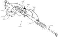
Figure 4 is a perspective view schematically showing an automobile steering device according to an embodiment of the present invention.
Figure 5 is a cross-sectional view showing the first steering engine of Figure 4.
Figure 6 is a cross-sectional view showing another embodiment of the first steering engine.
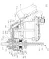
Figure 7 is a cross-sectional view showing the gearbox of Figure 4.
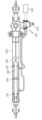
Figure 8 is a cross-sectional view showing another embodiment of the second steering engine.
이하, 본 발명의 일부 실시예들을 예시적인 도면을 통해 상세히 설명한다. 각 도면의 구성 요소들에 참조부호를 부가함에 있어서, 동일한 구성 요소들에 대해서는 비록 다른 도면상에 표시되더라도 가능한 한 동일한 부호를 가지도록 하고 있음에 유의해야 한다. 또한, 본 발명을 설명함에 있어서, 관련된 공지 구성 또는 기능에 대한 구체적인 설명이 본 발명의 요지를 흐릴 수 있다고 판단되는 경우에는 그 상세한 설명은 생략한다.Hereinafter, some embodiments of the present invention will be described in detail through illustrative drawings. When adding reference numerals to components in each drawing, it should be noted that the same components are given the same reference numerals as much as possible even if they are shown in different drawings. Additionally, in describing the present invention, if it is determined that a detailed description of a related known configuration or function may obscure the gist of the present invention, the detailed description will be omitted.
또한, 본 발명의 구성 요소를 설명하는데 있어서, 제1, 제2, A, B, (a), (b) 등의 용어를 사용할 수 있다. 이러한 용어는 그 구성 요소를 다른 구성 요소와 구별하기 위한 것일 뿐, 그 용어에 의해 해당 구성 요소의 본질이나 차례 또는 순서 등이 한정되지 않는다. 어떤 구성 요소가 다른 구성 요소에 "연결", "결합" 또는 "접속"된다고 기재된 경우, 그 구성 요소는 그 다른 구성 요소에 직접적으로 연결되거나 또는 접속될 수 있지만, 각 구성 요소 사이에 또 다른 구성 요소가 "연결", "결합" 또는 "접속"될 수도 있다고 이해되어야 할 것이다.Additionally, in describing the components of the present invention, terms such as first, second, A, B, (a), and (b) may be used. These terms are only used to distinguish the component from other components, and the nature, sequence, or order of the component is not limited by the term. When a component is described as being “connected,” “coupled,” or “connected” to another component, that component may be directly connected or connected to that other component, but there is another component between each component. It will be understood that elements may be “connected,” “combined,” or “connected.”
도 3은 본 발명의 실시예들에 의한 자동차 조향장치를 나타내는 구성도이며, 도 4는 본 발명의 일실시예에 의한 자동차 조향장치를 개략적으로 나타낸 사시도이고, 도 5는 도 4의 제1조향동력기를 나타내는 단면도이며, 도 6은 제1조향동력기의 다른 실시예를 나타내는 단면도이고, 도 7은 도 4의 기어박스를 나타내는 단면도이며, 도 8은 제2조향동력기의 다른 실시예를 나타내는 단면도이다.Figure 3 is a configuration diagram showing an automobile steering device according to an embodiment of the present invention, Figure 4 is a perspective view schematically showing an automobile steering device according to an embodiment of the present invention, and Figure 5 is the first steering device of Figure 4. It is a cross-sectional view showing the power machine, Figure 6 is a cross-sectional view showing another embodiment of the first steering engine, Figure 7 is a cross-sectional view showing the gearbox of Figure 4, and Figure 8 is a cross-sectional view showing another embodiment of the second steering engine. .
이들 도면에 도시된 바와 같이 본 발명의 실시예들에 따른 자동차 조향장치는 조향축(381)의 회전 토크를 감지하는 토크센서(302)로부터 입력된 제1입력신호와 위치센서(303), 카메라센서(304), 거리센서(305), 차속센서(306), 차고센서(307) 중 어느 하나로부터 입력되는 제2입력신호에 따라 조향 제어신호를 송출하는 제어부(308), 제어부(308)로부터 입력된 조향 제어신호에 따라 전기력으로 조향축(381)을 회전시켜 조향력을 생성하거나 정방향 또는 역방향으로 회전하는 조향축(381)의 조향력을 보조하는 제1조향동력기(310), 조향축(381)의 정방향 또는 역방향의 회전에 따라 작동유의 유로가 변경되며 작동유의 유압으로 타이로드 또는 너클을 작동시켜 바퀴(309)를 조향하는 제2조향동력기(320)를 포함한다.As shown in these drawings, the automobile steering device according to embodiments of the present invention includes a first input signal input from the
제어부(308)에는 토크센서(302)로부터 제1입력신호가 입력되며 위치센서(303), 카메라센서(304), 거리센서(305), 차속센서(306), 차고센서(307) 중 어느 하나로부터 제2입력신호가 입력된다.The first input signal is input from the
즉, 운전자가 조향휠(301)을 조작시 조향휠(301)과 연동되어 회전하는 조향축(381)의 회전방향과 토크값을 감지하는 토크센서(302)가 운전자가 좌회전을 하는지 또는 우회전을 하는지와, 조향휠(301)을 조작하는 토크를 감지하면, 이러한 운전자의 조향의지인 제1입력신호를 제어부(308)로 송출하게 된다.That is, when the driver operates the
또한, 자동차에 구비되는 위치센서(303)에서 자동차의 위치를 감지하거나, 카메라센서(304)에서 자동차가 주행중인 차선 또는 주변 상황을 감지하거나, 거리센서(305)에서 자동차의 주변에 장애물 또는 사람이 있는지를 감지하거나, 차속센서(306)에서 자동차의 속도를 감지하거나, 차고센서(307)에서 자동차의 노면으로부터의 높이를 감지하여 노면상태를 체크하면 이러한 제2입력신호를 제어부(308)로 송출하게 된다.In addition, the
제1조향동력기(310)는 제1조향동력기(310)는 모터(311)의 구동력을 이용한 전기식 조향동력기이며, 조향휠과 연결된 조향축(381)이 회전하여 토크센서에서 제어부로 제1입력신호를 입력함으로 인해 모터가 구동되어 작동되거나, 위치센서(303), 카메라센서(304), 거리센서(305), 차속센서(306), 차고센서(307) 중 어느 하나에서 제어부(308)로 제2입력신호를 입력함으로 인해 모터가 구동되어 작동될 수 있다.The
제2조향동력기(320)는 입력축(329)의 회전방향에 따라 유로가 변경되는 유압을 이용한 유압식 조향동력기이며, 입력축(329)의 회전에 따라 유로가 변경됨으로 인해 작동유가 제1실린더(353)와 제2실린더(355)에 각각 유입되면서 유압이 조정되어 섹터샤프트(351)를 회전시키거나, 작동유가 랙바(362)의 피스톤(364)으로 나뉘는 양측 유압관에 각각 유입되면서 유압이 조정되어 랙바(362)를 슬라이딩시켜 바퀴(309)를 조향하게 된다.The
이때, 운전자가 조향휠(301)을 회전시키지 않으면 조향축(381)과 연결되는 입력축(329)이 회전되지 않기 때문에 제2조향동력기(320)를 작동시킬 수 없어서, 운전자의 조향의지와 무관하게 제2조향동력기(320)를 작동시키도록 제1조향동력기(310)가 구비된다.At this time, if the driver does not rotate the
제1조향동력기(310)는 운전자의 조향의지와 무관하게 제어부(308)의 조향 제어신호에 따라 작동될 수 있으며, 제어부(308)에 제2입력신호가 입력되어 운전자의 조향의지와 무관하게 제1조향동력기(310)와 제2조향동력기(320)가 작동될 수 있다.The first
이러한 제1조향동력기(310)는 부가기능을 수행하기 위해 작동될 수 있으며, 위치센서(303), 카메라센서(304), 거리센서(305), 차속센서(306), 차고센서(307)로부터 입력되는 제2입력신호에 따라 작동될 수 있다.This
또한, 제어부(308)가 제2입력신호에 따라 모터(311)에 조향 입력신호를 송출하여 제1조향동력기(310)가 작동되다가, 제어부(308)에 제1입력신호가 입력되면, 즉, 운전자의 조향의지가 입력되면, 제어부가 운전자의 조향의지를 우선하는 조향 제어신호를 모터(311)에 송출하며 제1조향동력기(310)는 운전자의 조향의지대로 작동된다.In addition, the
이러한 제2입력신호를 송출하는 위치센서(303), 카메라센서(304), 거리센서(305), 차속센서(306), 차고센서(307)에 대해 좀더 설명하면, 위치센서(303)는 일예로 GPS정보 등을 이용하여 자동차의 위치를 감지하며 자동차의 주행도로의 특징이나 주행경로 등을 전송받아 이를 제어부(308)로 송출하게 된다.To further explain the
카메라센서(304)는 탑재된 차량의 주변을 촬영하고, 촬영결과 얻어진 영상데이터를 토대로 차선인식 등을 수행하여 차량이 차선을 유지하여 주행하거나 차량이 자동으로 주차될 수 있도록 이를 제어부(308)로 송출하게 된다.The
거리센서(305)는 일예로 레이더나 초음파일 수 있으며, 레이더빔 또는 초음파빔을 발사한 후 반사되어 돌아오는 시간 또는 위치 등을 인식하여 주변 장애물 또는 사람이 있는지를 감지하며 이를 제어부(308)로 송출하게 된다.The
차속센서(306)는 차량의 차속을 검출하여 이를 제어부(308)로 송출하게 되며, 차고센서(307)는 탑재된 차량의 위치로부터 노면까지의 거리를 감지하여 이를 제어부(308)로 송출하게 된다.The
이어서 제어부(308)는 이들 제1입력신호에 따라 조향 제어신호를 발생하여 제1조향동력기(310)의 모터(311)로 송출하면 제1조향동력기(310)가 운전자의 조향휠(301)을 조작하는 방향으로 조작력을 보조하며, 제어부(308)가 운전자의 조향의지를 우선하는 조향 제어신호를 발생하여 제1조향동력기(310)의 모터(311)로 송출하면 제1조향동력기(310)가 운전자의 조향의지와 무관하게 차량을 제어하는 조향휠(301)의 조작력을 생성한다.Then, the
여기서 제2입력신호에 따른 조향 제어신호로는 위치센서(303), 카메라센서(304), 거리센서(305), 차속센서(306), 차고센서(307) 중 어느 하나 또는 둘 이상을 이용하여 운전자를 보조하는 기능으로, 일예로, 자동 주차, 차선유지, 트레일러 백업 보조, 노면상태에 따른 주행보조. 조향진동 감쇠, 자율주행제어 등의 부가기능일 수 있다.Here, as the steering control signal according to the second input signal, one or more of the
이러한 부가기능에 대해 설명하면, 자동 주차의 부가기능은 운전자의 조작 없이 차량을 주차공간에 주차시키는 기능이며, 차선유지의 부가기능은 운전자가 조향하지 않아도 차선을 인식하여 차선을 유지하는 기능이고, 노면상태에 따른 주행보조의 부가기능은 노면이 경사지거나 횡방향으로 휘어있어도 차량이 어느한측으로 기울어지지 않게 하는 기능이다.To explain these additional functions, the additional function of automatic parking is a function that parks the vehicle in a parking space without driver intervention, and the additional function of lane maintenance is a function that recognizes the lane and maintains the lane even without the driver's steering. An additional function of driving assistance according to road surface conditions is a function that prevents the vehicle from leaning to one side even if the road surface is inclined or curved laterally.
또한, 트레일러 백업 보조의 부가기능은 운전자가 조향휠(301)을 회전시켜 조향축(381)을 통해 회전력을 전달하는 직접적인 조향이 아닌, 보조수단(예를 들면, 별도의 조그, 버튼, 컨트롤 장치 등)을 이용하여 차량을 조향시키는 기능이다.In addition, the additional function of trailer backup assistance is not direct steering in which the driver rotates the
다시 말해서, 예를들어 보조수단이 별도의 조그인 경우 조그를 우측으로 돌리면 차량을 우측으로 조향시키는 조향정보인 제2입력신호가 제어부(308)에 입력되며, 제어부(308)는 우측으로 조향시키는 조향정보와 대응되는 조향 제어신호를 모터(311)에 송출하여 제1조향동력기(310)가 조향축(381)을 회전시키고, 이와 연결된 제2조향동력기(320)의 입력축(329)에 조향력이 전달되어 제2조향동력기(320)가 작동되면서 차량의 조향이 이루어지게 된다.In other words, for example, if the auxiliary means is a separate jog, when the jog is turned to the right, the second input signal, which is steering information for steering the vehicle to the right, is input to the
또한, 조향진동 감쇠의 부가기능은 노면으로부터 입력되는 진동을 감쇠하는 기능으로, 노면으로부터 입력되는 진동의 주파수를 감지한 후 이를 상쇄시키는 주파수를 발생시켜 조향축(381)을 통해 조향휠(301)에 노면으로부터 입력되는 진동이 전달되는 것을 방지하는 기능이다.In addition, the additional function of damping steering vibration is a function of attenuating vibration input from the road surface. After detecting the frequency of vibration input from the road surface, a frequency that cancels it is generated, and the
이러한 부가기능은 제어부(308)가 제2입력신호에 따른 조향 제어신호를 모터(311)로 송출하여 제1조향동력기(310)로 조향력을 생성하며, 생성된 조향력은 제2조향동력기(320)의 입력축(329)을 회전시켜 제2조향동력기(320)가 차량을 조향하게 되는 것이다.In this additional function, the
이러한 제1조향동력기(310)는 제어부(308)로부터 입력된 조향 제어신호에 따라서 운전자의 조향휠(301) 회전방향과 같은 방향으로 조향축(381)을 회전시킴으로써 운전자의 조향의지를 반영하여 조향력을 보조하거나 운전자의 조향의지와 무관하게 조향력을 생성하게 되어 있다.This
이러한 제1조향동력기(310)는 운전자의 조향의지를 반영하는 경우 토크센서(302)에서 감지되는 제1입력신호에 따라 모터(311)에 조향 제어신호가 송출되어 모터(311)가 구동되며 운전자의 조향방향과 동일한 방향으로 조향축(381)을 회전시키며, 운전자의 조향력을 보조한다.When the first
또한, 제1조향동력기(310)는 운전자의 조향의지와 무관하게 조향력을 생성하는 경우 위치센서(303), 카메라센서(304), 거리센서(305), 차속센서(306), 차고센서(307) 중 어느 하나로부터 감지되는 제2입력신호에 따라 모터(311)에 조향 제어신호가 송출되어 모터(311)가 구동되며 조향축(381)을 회전시키며, 조향축(381)이 회전되어 조향력을 생성한다.In addition, when the
또한, 운전자의 조향의지와 무관하게 상기 제1조향동력기(310)와 제2조향동력기(320)가 작동되다가 제어부(308)에 상기 제1입력신호가 입력되는 경우, 제어부(308)는 운전자의 조향의지를 우선하는 조향 제어신호를 모터(311)로 송출한다.In addition, when the first
다시말해서, 운전자의 조향의지와 무관하게 제1조향동력기(310)가 조향력을 생성하여 제2조향동력기(320)를 작동시키다가, 운전자의 조향에 따라 제1입력신호가 입력되면 제어부(308)에서는 운전자의 조향의지를 우선하는 조향 제어신호를 모터(311)에 송출하여 제1조향동력기(310)와 제2조향동력기(320)가 운전자의 조향력을 보조하게 된다.In other words, the first
여기서, 제1조향동력기(310)는 모터(311)의 구동력을 이용한 전기식 조향동력기로서, 제어부(308)로부터 입력되는 조향 제어신호에 따라 전기력으로 조향축(381)을 회전시켜 조향력을 생성하거나 정방향 또는 역방향으로 회전하는 조향축(381)의 조향력을 보조한다.Here, the
이러한 제1조향동력기(310)는 조향축(381) 중에서 컬럼부(380)와 제2조향동력기(320) 사이에 위치되는 중간축(318)에 구비되어 제2조향동력기(320)에 조향력을 제공한다.This
중간축(318)은 컬럼부(380)에 연결되는 조향입력축(316)과 제2조향동력기(320)에 연결되는 조향출력축(317)이 토션바(319)를 매개로 연결되며, 조향입력축(316)과 조향출력축(317)의 외측에 토크센서(302)가 구비되어 조향입력축(316)과 조향출력축(317)의 토크를 감지하여 제어부(308)로 송출한다.The
이와 같이 제1조향동력기(310)의 조향입력축(316)과 조향출력축(317)이 토션바(319)로 연결되어 결합되며 토크센서(302)가 구비됨에 따라 운전자의 조향의지와 무관하게 자동차를 제어하다가 운전자가 조향휠(301)을 회전시키면 토크센서(302)에서 이를 인식하여 운전자의 조향의지를 반영하여 조향력을 보조하거나 생성함에 따라 운전자의 안전성을 높인다.In this way, the steering
일예로, 도 5를 참조하면, 제1조향동력기(310)는 조향출력축(317)과 연결되어 회전하는 종동풀리(314)와, 종동풀리(314)와 연결되는 벨트(315)와, 벨트(315)와 연결되어 종동풀리(314)를 회전시키는 구동풀리(312)를 포함하는 감속기(313), 및 제어부(308)로부터 입력된 조향 제어신호에 따라 구동풀리(312)를 정방향 또는 역방향으로 구동하는 모터(311)를 포함하여 구성된다.For example, referring to FIG. 5, the
제1조향동력기(310)는 모터(311)의 구동력으로 중간축(318)에 조향력을 제공하도록, 조향축(381)에 모터(311)의 회전수를 적당한 조향축(381)의 회전으로 조정하는 감속기(313)가 결합된다.The first
감속기(313)는, 모터(311)의 구동력에 의해 벨트(315)로 연결되는 종동풀리(314)와 조향출력축(317)이 연동되어 기어비에 따라 감속되면서 중간축(318)을 회전시키며, 크게 모터축(311a)에 결합되는 구동풀리(312), 조향출력축(317)에 결합되는 종동풀리(314), 구동풀리(312)와 종동풀리(314)를 연결하는 벨트(315)로 구성된다.The
종동풀리(314)는 중심에 조향출력축(317)을 연결하여 같이 연동되어 회전하게 하고, 종동풀리(314)와 벨트(315)로 연결되는 구동풀리(312)가 모터(311)의 구동력으로 회전하면서 종동풀리(314)와 조향출력축(317)을 회전시켜 조향력을 보조하거나 조향력을 생성한다.The driven
이때 모터(311)는 제어부(308)로부터 입력된 조향 제어신호에 따라서 구동풀리(312)를 회전시켜 종동풀리(314)와 조향출력축(317)을 정방향 또는 역방향으로 회전시킴으로써, 운전자의 조향휠(301) 조작력을 보조하거나 운전자의 조향휠(301) 조작력을 대신하여 입력축(329)을 회전시키며 제2조향동력기(320)를 작동시킨다.At this time, the
이러한 구동풀리(312)는 외주면에 기어가 형성되어 벨트(315)와 치합되며, 중공형상으로 형성되어 모터축(311a)에 압입되어 결합되거나, 모터축(311a)에 일체로 형성될 수도 있다.This drive
일예로 도면에 도시된 것처럼, 구동풀리(312)가 모터축(311a)에 일체로 형성되는 경우 모터축(311a)의 끝단에 벨트(315)와 치합되는 기어가 형성되며, 모터축(311a)의 기어가 형성되는 부분에 벨트(315)가 치합되어 연결된다.For example, as shown in the drawing, when the
이러한 종동풀리(314)는 외주면에 풀리기어(314a)가 형성되어 벨트(315)와 치합되며, 내주면에는 조향출력축(317)이 압입 결합되어 회전된다.This driven
또한, 종동풀리(314)에는 경방향 내측으로 돌출 형성되어 조향출력축(317)에 결합되는 연결부(314b)가 형성되어 종동풀리(314)가 조향출력축(317)에 결합되면서 풀리기어(314a)의 직경이 크게 형성될 수 있으며, 구동풀리(312)와 종동풀리(314)의 감속비가 커져 조향출력축(317)이 출력하는 토크가 커지게 된다.In addition, the driven
즉, 종동풀리(314)의 직경이 구동풀리(312)의 직경보다 크게 형성되되 원하는 기어비를 맞추기 위해 종동풀리(314)의 내주면에 경방향으로 돌출 형성되는 연결부(314b)가 구비된다.That is, the diameter of the driven
또한, 조향출력축(317)에는 외주면 일측에서 단턱지며 돌출되는 걸림턱부(317a)가 형성되며, 연결부(314b)에는 내주면 일측에서 단턱지며 함몰되는 삽입홈(314c)이 형성되어 삽입홈(314c)에 걸림턱부(317a)가 삽입되어 결합된다.In addition, the
즉, 조향출력축(317)에는 걸림턱부(317a)가 형성되며 종동풀리(314)에는 삽입홈(314c)이 형성되어 걸림턱부(317a)에 삽입홈(314c)이 결합되면서 조향출력축(317)에 종동풀리(314)가 결합되어 종동풀리(314)가 조향출력축(317)을 회전시킨다.That is, a locking
이러한 조향출력축(317)과 종동풀리(314)는 일예로 압입되어 결합될 수 있으며, 압입된 후에도 삽입홈(314c)에 걸림턱부(317a)가 삽입되어 있어서 조향출력축(317)과 종동풀리(314) 사이가 안정적으로 결합될 수 있게 된다.For example, the
또한, 조향출력축(317)과 종동풀리(314)는 조향출력축(317)과 일체로 형성될 수도 있으며, 조향출력축(317)의 일측에서 연결부(314b)가 경방향 외측으로 돌출 형성되고 연결부(314b)의 돌출된 끝단에 풀리기어(314a)가 형성되어 벨트(315)가 연결될 수도 있다.In addition, the
또한, 이러한 벨트(315), 조향출력축(317), 토크센서(302)를 감싸는 벨트하우징(345)이 더 구비될 수 있으며, 벨트하우징(345)은 내측에 벨트(315), 조향출력축(317), 토크센서(302)가 구비되되 조향출력축(317)이 제1베어링(341)과 제2베어링(342)을 매개로 결합되어 구비된다.In addition, a
이러한 벨트하우징(345)은 벨트(315), 조향출력축(317), 토크센서(302)를 감싸 외부로부터 보호하며 내측으로 먼지 등이 유입되는 것을 방지한다.This
여기서 제1베어링(341)은 일예로 볼베어링으로 구비되어 조향출력축(317)의 축방향 및 경방향 하중을 지지해준다.Here, the
또한, 제1베어링(341)의 내륜은 일측이 조향출력축(317)에서 경방향 외측으로 돌출 형성되는 제1단턱부(317b)에 지지되며 타측이 조향출력축(317)에 나사결합되어 구비되는 락너트(371)에 지지된다.In addition, the inner ring of the
또한, 제1베어링(341)의 외륜은 일측이 벨트하우징(345)에서 경방향 내측으로 돌출 형성되는 제2단턱부(345a)에 지지되며 타측이 벨트하우징(345)의 개구되는 단부에 나사결합되어 구비되는 락스크류(372)에 지지된다.In addition, the outer ring of the
또한, 락스크류(372)는 벨트하우징(345)의 내측에 나사결합되어 일측에 제1베어링(341)의 외륜의 타측이 지지되며, 타측에 제1수밀부재(373)가 압입되어 결합되어 벨트하우징(345) 내측으로 먼지 또는 수분이 유입되는 것을 방지한다.In addition, the
이러한 제1수밀부재(373)는 락스크류(372)의 타측 내주면과 조향출력축(317) 사이에 구비되어 벨트하우징(345) 내측으로 먼지 또는 수분이 유입되는 것을 방지한다.This first
제2베어링(342)은 일예로 니들베어링으로 구비되어 조향출력축(317)의 경방향 하중을 지지해주어 조향출력축(317)이 벨트하우징(345) 내에 안정적으로 결합된다.The
또한, 벨트하우징(345)의 일측에 모터(311)가 결합되는 커버하우징(347)이 더 구비될 수도 있으며, 커버하우징(347)은 벨트하우징(345)에 체결부재(349)로 결합된다.In addition, a
이러한 커버하우징(347)이 구비되어 모터(311)가 벨트하우징(345)에 결합될 수 있으며 벨트하우징(345)의 조향입력축(316)이 결합되는 개구부위를 밀폐시킨다.This
또한, 커버하우징(347)의 벨트하우징(345)과 결합되는 부위의 반대쪽에는 제2수밀부재(374)가 구비되어 커버하우징(347)의 내측으로 먼지 또는 수분 등이 유입되는 것을 방지한다.In addition, a second
또한, 조향입력축(316)과 조향출력축(317) 사이에도 제3베어링(343)이 결합되어 구비됨에 따라 조향입력축(316)과 조향출력축(317) 사이의 경방향 하중을 지지해주며, 일예로 제3베어링(343)은 니들베어링으로 구비될 수도 있다.In addition, as the
이러한 제3베어링(343)은 조향입력축(316)과 조향출력축(317) 사이에 토크가 발생되면서 토션바(319)가 비틀릴 때 조향입력축(316)과 조향출력축(317) 사이의 회전방향 유동을 지지하며, 조향입력축(316)과 조향출력축(317) 사이의 경방향 하중을 지지해준다.This
또한, 제1조향동력기(310)는 다른 예로, 도 6에 도시된 것처럼, 조향출력축(317)과 연결되어 회전하는 웜휠(368)과, 웜휠(368)과 치합되어 조향출력축(317)과 연결된 웜휠(368)을 회전시키는 웜축(369)을 포함하는 감속기(313), 및 제어부(308)로부터 입력된 조향 제어신호에 따라 웜축(369)을 정방향 또는 역방향으로 구동하는 모터(311)를 포함하여 구성된다.In addition, as another example, the
제1조향동력기(310)는 모터(311)의 구동력으로 조향출력축(317)을 회전시키도록, 조향출력축(317)에 모터(311)의 회전수를 적당한 조향출력축(317)의 회전으로 조정하는 감속기(313)가 결합된다.The
감속기(313)는, 모터(311)의 구동력에 의해 웜축(369)과 웜휠(368)이 연동되어 기어비에 따라 감속되면서 조향출력축(317)을 회전시킨다.The
이러한 웜휠(368)은 중심에 조향출력축(317)을 연결하여 같이 연동되어 회전하게 하고, 이 웜휠(368)과 치합되는 웜축(369)이 모터(311)의 구동력으로 회전하면서 웜휠(368)을 회전시켜 조향축(381)의 조향력을 보조하거나 조향력을 생성한다.This
이때 모터(311)는 제어부(308)로부터 입력된 조향 제어신호에 따라서 웜축(369)을 정방향 또는 역방향으로 회전시킴으로써, 운전자의 조향휠(301) 조작력을 보조하거나 운전자의 조향휠(301) 조작력을 대신하여 입력축(329)을 회전시키며 제2조향동력기(320)를 작동시킨다.At this time, the
그리고, 제2조향동력기(320)는 입력축(329)의 회전방향에 따라 유로가 변경되는 유압을 이용한 유압식 조향동력기로서, 작동유의 유압에 따라 운전자의 조향력을 보조하게 된다.In addition, the second
이러한 제2조향동력기(320)는 일예로 도 7을 참조하면, 입력축(329)의 정방향 또는 역방향의 회전에 따라 작동유의 유압으로 기어박스(325)의 섹터샤프트(351)를 정방향 또는 역방향으로 회전시키며 조향력을 보조한다.Referring to FIG. 7 as an example, this
제2조향동력기(320)는 오일펌프(323)의 유압을 이용한 유압식 조향동력기로서, 작동유의 유압에 따라 스크류너트(337)가 일측방향 또는 타측방향으로 슬라이딩되면서 섹터샤프트(351)를 회전시켜 운전자의 조향력을 보조하게 된다.The
이러한 제2조향동력기(320)는 조향출력축(317)과 결합되는 입력축(329)이 회전하면, 볼스크류 토션바(331)를 매개로 입력축(329)과 결합된 볼스크류(335)가 회전하고, 볼스크류(335)와 볼을 매개로 결합된 스크류너트(337)가 회전하면서 섹터샤프트(351)를 회전하게 된다.In this
볼스크류(335)는 외주면에 스크류홈이 형성되어 있고, 볼스크류(335)가 삽입되는 스크류너트(337)는 내주면에 볼스크류(335)의 스크류홈과 대응되는 스크류홈이 형성되어 이들 스크류홈에 수개의 볼이 결합된다.The
스크류너트(337)는 외주면에 기어치(337a)가 형성되어 이와 맞물리는 기어치(351a)가 형성된 섹터샤프트(351)를 구동하게 되어 있다.The
그리고, 섹터샤프트(351)는 피트먼암(360)과 결합되어 있어서, 섹터샤프트(351)의 회전시 피트먼암(360)의 타단에 결합된 링크에 의해 타이로드 또는 너클을 작동시켜 바퀴(309)를 조향시키게 된다.In addition, the
이때 입력축(329)의 회전시 이를 감싸며 결합된 밸브바디(333)의 수개의 작동유 유출입홀을 통해 작동유가 기어박스 하우징(339)의 제1실린더(355) 또는 제2실린더(353)로 유입되면서 작동유의 유압에 의해 스크류너트(337)를 일측방향 또는 타측방향으로 슬라이딩시키게 되어 입력축(329)과 볼스크류(335)의 회전력 즉, 조향력을 보조하게 된다.At this time, when the
또한, 밸브바디(333)의 수개의 작동유 유출입홀은 입력축(329)의 회전방향에 따라 작동유의 유로가 변경되며, 입력축(329)의 회전방향과 대응되게 섹터샤프트(351)를 회전시키도록 작동유가 제1실린더(353)와 제2실린더(355)에 각각 유입되면서 작동유의 유압으로 인해 볼스크류(335)가 회전하며 스크류너트(337)를 구동시킨다.In addition, the hydraulic oil flow path of the several hydraulic oil inflow and outflow holes of the
또한, 제2조향동력기(320)는 다른 예로 도 8을 참조하면, 조향축(381)의 정방향 또는 역방향의 회전에 따라 작동유의 유압으로 랙바(362)를 정방향 또는 역방향으로 슬라이딩시키며 조향력을 보조한다.In addition, referring to FIG. 8 as another example, the second
이러한 제2조향동력기(320)는 크게 입력축(329)과 연결되는 피니언 밸브 어셈블리(361), 그리고 피니언 밸브 어셈블리(361)의 동작에 따라 바퀴(309)를 직접 동작시킬 수 있도록 좌, 우 양측으로 연장되어 바퀴(309)에 연결되는 랙바(362)를 포함한다.This
입력축(329)에는 측면에 오일펌프(323)가 연결된 피니언 밸브 어셈블리(361)가 마련되며, 피니언 밸브 어셈블리(361)는 오일펌프(323)를 통해 공급되는 오일을 조절한다.A
피니언 밸브 어셈블리(361)의 내부에는 입력축(329)을 통해 전달된 회전력에 의해 회전하며 끝단 외주부에 이가 형성된 피니언(미도시)이 구비되고 피니언 밸브 어셈블리(361)의 하부 외측에는 피니언 밸브 어셈블리(361)와 일체로 형성되며 양측으로 연장되는 랙하우징(363)이 구비된다.Inside the
랙하우징(363)의 일측에는 실린더 튜브(365)가 압입되어 연결되는데 실린더 튜브(365)는 피니언 밸브 어셈블리(361)를 통해 공급되는 오일이 유동되는 공간을 형성할 수 있도록 마련되는 중공관으로서 양측이 개구되어 형성되며, 개구된 양측에는 오일씰(367) 등이 설치된다.A
또한, 랙하우징(363)의 내부에는 일측에 피니언과 치합되는 랙기어가 형성된 랙바(362)가 구비된다.In addition, a
랙바(362)는 랙하우징(363)의 내부에서 축방향으로 이동되며, 피니언과 치합되는 랙기어가 형성되고, 랙바(362)의 좌,우측은 볼 하우징에 볼이 삽입되어 결합되는 이너 볼 조인트를 매개로 타이로드와 연결되어 바퀴(309)를 조향한다.The
또한, 랙바(362)의 일측에는 실린더 튜브(365)의 내부면과 밀착되어 그 안에서 슬라이딩 될 수 있도록 피스톤(364)이 구비되는데, 이 피스톤(364)은 피니언 밸브 어셈블리(361)와 연결된 두 개의 유압관 사이에 설치되어 피니언 밸브 어셈블리(361)를 통해 공급되는 유압에 의해 작동된다.In addition, a
이러한 형상과 구조를 갖는 본 발명의 실시예들에 의하면 운전자가 직접 조향하지 않아도 유압식 조향동력기의 입력축을 회전시키는 전기식 조향동력기가 구비됨에 따라 승용차에 비하여 상대적으로 큰 조향력이 필요한 트럭이나 버스의 경우에도 운전자의 조향의지와 무관하게 자동차를 제어하는 자동 주차, 차선유지, 트레일러 백업 보조, 노면상태에 따른 주행보조. 조향진동 감쇠, 자율주행제어 등의 부가기능을 사용할 수 있어 운전자의 편의성을 높이는 효과가 있다.According to embodiments of the present invention having such a shape and structure, an electric steering engine is provided that rotates the input shaft of the hydraulic steering engine without the driver directly steering, so even in the case of trucks or buses that require a relatively large steering force compared to passenger cars. Automatic parking that controls the car regardless of the driver's steering intention, lane maintenance, trailer backup assistance, and driving assistance depending on road conditions. Additional functions such as steering vibration damping and autonomous driving control can be used, which has the effect of increasing driver convenience.
또한, 전기식 조향동력기에 토션바가 구비되어 있어서 운전자의 조향의지와 무관하게 자동차를 제어하다가 운전자가 조향휠을 회전시키면 토크센서에서 이를 인식하여 운전자의 조향의지를 반영하여 조향력을 보조하거나 생성함에 따라 운전자의 안전성을 높이는 효과가 있다.In addition, the electric steering engine is equipped with a torsion bar, so the car is controlled regardless of the driver's steering intention. When the driver rotates the steering wheel, the torque sensor recognizes this and assists or generates steering force by reflecting the driver's steering intention. It has the effect of increasing safety.
이상에서, 본 발명의 실시예를 구성하는 모든 구성 요소들이 하나로 결합되거나 결합되어 동작하는 것으로 설명되었다고 해서, 본 발명이 반드시 이러한 실시예에 한정되는 것은 아니다. 즉, 본 발명의 목적 범위 안에서라면, 그 모든 구성 요소들이 하나 이상으로 선택적으로 결합하여 동작할 수도 있다.In the above, even though all the components constituting the embodiment of the present invention have been described as being combined or operated in combination, the present invention is not necessarily limited to this embodiment. That is, as long as it is within the scope of the purpose of the present invention, all of the components may be operated by selectively combining one or more of them.
이상의 설명은 본 발명의 기술 사상을 예시적으로 설명한 것에 불과한 것으로서, 본 발명이 속하는 기술 분야에서 통상의 지식을 가진 자라면 본 발명의 본질적인 특성에서 벗어나지 않는 범위에서 다양한 수정 및 변형이 가능할 것이다. 따라서, 본 발명에 개시된 실시예들은 본 발명의 기술 사상을 한정하기 위한 것이 아니라 설명하기 위한 것이고, 이러한 실시예에 의하여 본 발명의 기술 사상의 범위가 한정되는 것은 아니다. 본 발명의 보호 범위는 아래의 청구범위에 의하여 해석되어야 하며, 그와 동등한 범위 내에 있는 모든 기술 사상은 본 발명의 권리범위에 포함되는 것으로 해석되어야 할 것이다.The above description is merely an illustrative explanation of the technical idea of the present invention, and various modifications and variations will be possible to those skilled in the art without departing from the essential characteristics of the present invention. Accordingly, the embodiments disclosed in the present invention are not intended to limit the technical idea of the present invention, but are for illustrative purposes, and the scope of the technical idea of the present invention is not limited by these embodiments. The scope of protection of the present invention should be interpreted in accordance with the claims below, and all technical ideas within the equivalent scope should be construed as being included in the scope of rights of the present invention.
301: 조향휠302: 토크센서
303: 위치센서304: 카메라센서
305: 거리센서306: 차속센서
307: 차고센서308: 제어부
309: 바퀴310: 제1조향동력기
311: 모터312: 구동풀리
313: 감속기314: 종동풀리
315: 벨트316: 조향입력축
317: 조향출력축318: 중간축
319: 토션바313: 감속기
320: 제2조향동력기329: 입력축301: Steering wheel 302: Torque sensor
303: Position sensor 304: Camera sensor
305: Distance sensor 306: Vehicle speed sensor
307: Ride height sensor 308: Control unit
309: Wheel 310: First steering engine
311: motor 312: driving pulley
313: Reducer 314: Driven pulley
315: Belt 316: Steering input shaft
317: Steering output axis 318: Intermediate axis
319: torsion bar 313: reducer
320: Second steering engine 329: Input shaft
Claims (16)
Translated fromKorean상기 제어부로부터 입력된 상기 조향 제어신호에 따라 전기력으로 상기 조향축을 회전시켜 조향력을 생성하거나 정방향 또는 역방향으로 회전하는 상기 조향축의 조향력을 보조하는 제1조향동력기; 및
상기 조향축의 정방향 또는 역방향의 회전에 따라 작동유의 유로가 변경되며 상기 작동유의 유압으로 타이로드 또는 너클을 작동시켜 바퀴를 조향하는 제2조향동력기;
를 포함하고,
상기 제1조향동력기는,
상기 조향축과 연결되어 회전하는 종동풀리와, 상기 종동풀리와 연결되는 벨트와, 상기 벨트와 연결되어 상기 종동풀리를 회전시키는 구동풀리를 포함하는 감속기; 및
상기 제어부로부터 입력된 상기 조향 제어신호에 따라 상기 구동풀리를 정방향 또는 역방향으로 구동하는 모터;
를 포함하며,
운전자의 조향의지와 무관하게 상기 제1조향동력기와 제2조향동력기가 작동되다가 상기 제어부에 상기 제1입력신호가 입력되는 경우, 상기 제어부는 운전자의 조향의지를 우선하는 상기 조향 제어신호를 상기 모터로 송출하여 상기 제1조향동력기와 제2조향동력기가 작동되는 것을 특징으로 하는 자동차 조향장치.A control unit that transmits a steering control signal according to the first input signal input from the torque sensor that detects the rotational torque of the steering shaft and the second input signal input from any one of the position sensor, camera sensor, distance sensor, vehicle speed sensor, and vehicle height sensor. ;
a first steering engine that generates steering force by rotating the steering shaft with electric force according to the steering control signal input from the control unit or assists the steering force of the steering shaft rotating in the forward or reverse direction; and
A second steering engine that changes the flow path of the hydraulic oil as the steering shaft rotates in the forward or reverse direction and operates a tie rod or knuckle with the hydraulic pressure of the hydraulic oil to steer the wheels;
Including,
The first steering engine,
A reducer including a driven pulley connected to and rotating with the steering shaft, a belt connected to the driven pulley, and a driving pulley connected to the belt to rotate the driven pulley; and
a motor that drives the drive pulley in a forward or reverse direction according to the steering control signal input from the control unit;
Includes,
When the first input signal is input to the controller while the first steering engine and the second steering engine are operated regardless of the driver's steering intention, the control unit transmits the steering control signal that prioritizes the driver's steering intention to the motor. An automobile steering device, characterized in that the first steering power and the second steering power are operated by transmitting to .
상기 제1조향동력기는 컬럼부에 연결되는 조향입력축과 상기 제2조향동력기에 연결되는 조향출력축이 토션바를 매개로 연결되며, 상기 토크센서가 상기 조향입력축과 조향출력축의 외측에 구비되어 상기 조향입력축과 조향출력축의 토크를 감지하여 상기 제어부로 송출하는 것을 특징으로 하는 자동차 조향장치.According to claim 1,
The first steering engine has a steering input shaft connected to the column portion and a steering output shaft connected to the second steering engine connected via a torsion bar, and the torque sensor is provided on the outside of the steering input shaft and the steering output shaft, so that the steering input shaft An automobile steering device characterized in that the torque of the steering output shaft is sensed and transmitted to the control unit.
상기 종동풀리는 외주면에 풀리기어가 형성되어 상기 벨트와 치합되며, 내주면에는 상기 조향출력축이 결합되어 회전되는 것을 특징으로 하는 자동차 조향장치.According to claim 3,
An automobile steering device, wherein a pulley gear is formed on the outer peripheral surface of the driven pulley and engages with the belt, and the steering output shaft is coupled and rotated on the inner peripheral surface.
상기 종동풀리에는 경방향 내측으로 돌출 형성되어 상기 조향출력축에 결합되는 연결부가 형성되는 것을 특징으로 하는 자동차 조향장치.According to claim 5,
An automobile steering device, characterized in that the driven pulley is formed with a connection part that protrudes radially inward and is coupled to the steering output shaft.
상기 조향출력축에는 외주면 일측에서 단턱지며 돌출되는 걸림턱부가 형성되며, 상기 연결부에는 내주면 일측에서 단턱지며 함몰되어 상기 걸림턱부가 삽입되는 삽입홈이 형성되는 것을 특징으로 하는 자동차 조향장치.According to claim 6,
An automobile steering device, characterized in that the steering output shaft is formed with a locking shoulder that is stepped and protrudes from one side of the outer peripheral surface, and the connecting portion is stepped and recessed on one side of the inner peripheral surface to form an insertion groove into which the locking shoulder is inserted.
상기 종동풀리는 상기 조향출력축과 일체로 형성되는 것을 특징으로 하는 자동차 조향장치.According to claim 6,
An automobile steering device, characterized in that the driven pulley is formed integrally with the steering output shaft.
내측에 상기 벨트, 조향출력축, 토크센서가 구비되되 상기 조향출력축이 제1베어링과 제2베어링을 매개로 결합되어 구비되는 벨트하우징을 더 포함하는 것을 특징으로 하는 자동차 조향장치.According to claim 3,
An automobile steering device, characterized in that it further includes a belt housing inside which the belt, a steering output shaft, and a torque sensor are provided, and the steering output shaft is coupled to each other via a first bearing and a second bearing.
상기 벨트하우징에 체결부재로 결합되며, 일측에 상기 모터가 결합되는 커버하우징을 더 포함하는 것을 특징으로 하는 자동차 조향장치.According to clause 9,
An automobile steering device coupled to the belt housing with a fastening member and further comprising a cover housing on one side of which the motor is coupled.
상기 조향입력축과 조향출력축 사이에 제3베어링이 결합되어 구비되는 것을 특징으로 하는 자동차 조향장치.According to claim 3,
An automobile steering device, characterized in that a third bearing is coupled between the steering input shaft and the steering output shaft.
상기 제어부로부터 입력된 상기 조향 제어신호에 따라 전기력으로 상기 조향축을 회전시켜 조향력을 생성하거나 정방향 또는 역방향으로 회전하는 상기 조향축의 조향력을 보조하는 제1조향동력기; 및
상기 조향축의 정방향 또는 역방향의 회전에 따라 작동유의 유로가 변경되며 상기 작동유의 유압으로 타이로드 또는 너클을 작동시켜 바퀴를 조향하는 제2조향동력기;
를 포함하고,
상기 제1조향동력기는,
상기 조향축과 연결되어 회전하는 웜휠과, 상기 웜휠과 치합되어 상기 조향축과 연결된 웜휠을 회전시키는 웜축을 포함하는 감속기; 및
상기 제어부로부터 입력된 상기 조향 제어신호에 따라 상기 웜축을 정방향 또는 역방향으로 구동하는 모터;
를 포함하며,
운전자의 조향의지와 무관하게 상기 제1조향동력기와 제2조향동력기가 작동되다가 상기 제어부에 상기 제1입력신호가 입력되는 경우, 상기 제어부는 운전자의 조향의지를 우선하는 상기 조향 제어신호를 상기 모터로 송출하여 상기 제1조향동력기와 제2조향동력기가 작동되는 것을 특징으로 하는 자동차 조향장치.A control unit that transmits a steering control signal according to the first input signal input from the torque sensor that detects the rotational torque of the steering shaft and the second input signal input from any one of the position sensor, camera sensor, distance sensor, vehicle speed sensor, and vehicle height sensor. ;
a first steering engine that generates steering force by rotating the steering shaft with electric force according to the steering control signal input from the control unit or assists the steering force of the steering shaft rotating in the forward or reverse direction; and
A second steering engine that changes the flow path of the hydraulic oil as the steering shaft rotates in the forward or reverse direction and operates a tie rod or knuckle with the hydraulic pressure of the hydraulic oil to steer the wheels;
Including,
The first steering engine,
A reducer including a worm wheel connected to the steering shaft and rotating, and a worm shaft engaged with the worm wheel to rotate the worm wheel connected to the steering shaft; and
a motor that drives the worm shaft in a forward or reverse direction according to the steering control signal input from the control unit;
Includes,
When the first input signal is input to the controller while the first steering engine and the second steering engine are operated regardless of the driver's steering intention, the control unit transmits the steering control signal that prioritizes the driver's steering intention to the motor. An automobile steering device, characterized in that the first steering power and the second steering power are operated by transmitting to .
상기 제1조향동력기는 컬럼부에 연결되는 조향입력축과 상기 제2조향동력기에 연결되는 조향출력축이 토션바를 매개로 연결되며, 상기 토크센서가 상기 조향입력축과 조향출력축의 외측에 구비되어 상기 조향입력축과 조향출력축의 토크를 감지하여 상기 제어부로 송출하는 것을 특징으로 하는 자동차 조향장치.According to claim 12,
The first steering engine has a steering input shaft connected to the column portion and a steering output shaft connected to the second steering engine connected via a torsion bar, and the torque sensor is provided on the outside of the steering input shaft and the steering output shaft, so that the steering input shaft An automobile steering device characterized in that the torque of the steering output shaft is sensed and transmitted to the control unit.
상기 제어부에 상기 제1입력신호와 제2입력신호가 동시에 입력되는 경우 상기 제1입력신호에 따라 상기 조향 제어신호를 상기 모터에 송출하는 것을 특징으로 하는 자동차 조향장치.According to claim 13,
An automobile steering device, characterized in that when the first input signal and the second input signal are simultaneously input to the control unit, the steering control signal is transmitted to the motor according to the first input signal.
상기 제2조향동력기는 상기 조향축의 정방향 또는 역방향의 회전에 따라 작동유의 유압으로 기어박스의 섹터샤프트를 정방향 또는 역방향으로 회전시키며 조향력을 보조하는 것을 특징으로 하는 자동차 조향장치.According to any one of claims 1, 3, 5 to 14,
The second steering power unit rotates the sector shaft of the gearbox in the forward or reverse direction with the hydraulic pressure of the hydraulic oil according to the forward or reverse rotation of the steering shaft and assists the steering force.
상기 제2조향동력기는 상기 조향축의 정방향 또는 역방향의 회전에 따라 작동유의 유압으로 랙바를 정방향 또는 역방향으로 슬라이딩시키며 조향력을 보조하는 것을 특징으로 하는 자동차 조향장치.According to any one of claims 1, 3, 5 to 14,
The second steering power unit is an automobile steering device characterized in that it assists steering force by sliding the rack bar in the forward or reverse direction with the hydraulic pressure of hydraulic oil according to the rotation of the steering shaft in the forward or reverse direction.
Priority Applications (4)
| Application Number | Priority Date | Filing Date | Title |
|---|---|---|---|
| KR1020160139115AKR102613788B1 (en) | 2016-10-25 | 2016-10-25 | Steering Apparatus for Vehicle |
| US15/791,324US10427713B2 (en) | 2016-10-25 | 2017-10-23 | Steering apparatus for vehicle |
| CN201711001051.6ACN107972728B (en) | 2016-10-25 | 2017-10-24 | Steering device for vehicles |
| DE102017219161.9ADE102017219161B4 (en) | 2016-10-25 | 2017-10-25 | STEERING DEVICE FOR A VEHICLE |
Applications Claiming Priority (1)
| Application Number | Priority Date | Filing Date | Title |
|---|---|---|---|
| KR1020160139115AKR102613788B1 (en) | 2016-10-25 | 2016-10-25 | Steering Apparatus for Vehicle |
Publications (2)
| Publication Number | Publication Date |
|---|---|
| KR20180045236A KR20180045236A (en) | 2018-05-04 |
| KR102613788B1true KR102613788B1 (en) | 2023-12-15 |
Family
ID=61866580
Family Applications (1)
| Application Number | Title | Priority Date | Filing Date |
|---|---|---|---|
| KR1020160139115AActiveKR102613788B1 (en) | 2016-10-25 | 2016-10-25 | Steering Apparatus for Vehicle |
Country Status (4)
| Country | Link |
|---|---|
| US (1) | US10427713B2 (en) |
| KR (1) | KR102613788B1 (en) |
| CN (1) | CN107972728B (en) |
| DE (1) | DE102017219161B4 (en) |
Families Citing this family (19)
| Publication number | Priority date | Publication date | Assignee | Title |
|---|---|---|---|---|
| WO2015149207A1 (en)* | 2014-03-31 | 2015-10-08 | 深圳市智行单轴双轮驱动技术有限公司 | Shock absorption mechanism of steering motor |
| US10177622B2 (en)* | 2014-03-31 | 2019-01-08 | Shenzhen Zhixing Single-Axle Two-Wheeled Driving Technology Co., Ltd. | Steering motor |
| US10793183B2 (en)* | 2017-12-22 | 2020-10-06 | Trw Automotive U.S. Llc | Torque overlay steering apparatus |
| US20210261188A1 (en)* | 2018-06-29 | 2021-08-26 | Mando Corporation | Electronic power steering apparatus |
| FR3083770B1 (en)* | 2018-07-10 | 2020-06-19 | Jtekt Europe | METHOD FOR CONTROLLING A STEERING SYSTEM WITH TWO REDUNDANT MOTORIZATIONS |
| KR102546961B1 (en)* | 2018-07-20 | 2023-06-23 | 현대모비스 주식회사 | Apparatus of steer by wire |
| JP7180334B2 (en)* | 2018-12-04 | 2022-11-30 | トヨタ自動車株式会社 | Steering system, steering support device |
| KR102644557B1 (en)* | 2018-12-07 | 2024-03-06 | 현대자동차주식회사 | Steering system for vehicle |
| SE542907C2 (en)* | 2018-12-11 | 2020-09-15 | Scania Cv Ab | A method for determining hydraulic failure in a hybrid steering system, a control device, a hybrid steering system and a vehicle |
| CN110104057B (en)* | 2019-04-24 | 2020-08-07 | 浙江吉利控股集团有限公司 | Vehicle steering assist control method, device, device and storage medium |
| KR102167914B1 (en)* | 2019-05-14 | 2020-10-20 | 주식회사 만도 | Steering Apparatus for Vehicle |
| KR102735499B1 (en)* | 2020-02-11 | 2024-11-29 | 에이치엘만도 주식회사 | Steering assist apparatus and method and, steering system |
| US11827290B2 (en)* | 2020-11-02 | 2023-11-28 | Ford Global Technologies, Llc | Rotary assist apparatus for recirculating ball steering gears |
| CN112298345B (en)* | 2020-11-04 | 2021-10-19 | 常熟理工学院 | Automatic driving automobile safety device for preventing steering shock and control method thereof |
| US11873037B2 (en) | 2021-03-04 | 2024-01-16 | Ford Global Technologies, Llc | Belt driven rotary assist apparatus for recirculating ball steering gears |
| DE102021109647A1 (en) | 2021-04-16 | 2022-10-20 | Knorr-Bremse Systeme für Nutzfahrzeuge GmbH | Driver torque and steering angle measurement in a torque overlay steering (TOS) |
| CN113911320B (en)* | 2021-10-09 | 2024-05-14 | 中国商用飞机有限责任公司 | Steering wheel mechanism |
| US20240300570A1 (en)* | 2023-03-09 | 2024-09-12 | Ford Global Technologies, Llc | Rotary assist apparatus for recirculating ball steering gears |
| US12077219B1 (en) | 2023-06-23 | 2024-09-03 | Ford Global Technologies, Llc | Rotary steering systems |
Citations (2)
| Publication number | Priority date | Publication date | Assignee | Title |
|---|---|---|---|---|
| WO2014103556A1 (en) | 2012-12-28 | 2014-07-03 | 日立オートモティブシステムズステアリング株式会社 | Power-steering device |
| JP2015009682A (en)* | 2013-06-28 | 2015-01-19 | 株式会社ジェイテクト | Vehicle steering system |
Family Cites Families (16)
| Publication number | Priority date | Publication date | Assignee | Title |
|---|---|---|---|---|
| DE10101827A1 (en)* | 2001-01-17 | 2002-07-18 | Daimler Chrysler Ag | Steering arrangement for motor vehicles |
| DE10256306A1 (en) | 2002-02-27 | 2003-10-30 | Continental Teves Ag & Co Ohg | Hydraulic power steering |
| DE102004060053A1 (en) | 2003-12-24 | 2005-12-22 | Continental Teves Ag & Co. Ohg | Hydraulic power steering for e.g. passenger car, has electric motor to apply driver-independent additional-steering moment for active, driver-independent application of electronic control and regulation unit, which has two interfaces |
| JP4608948B2 (en)* | 2004-05-27 | 2011-01-12 | 日産自動車株式会社 | Vehicle steering system |
| US7530422B2 (en)* | 2004-09-17 | 2009-05-12 | Delphi Technologies, Inc. | Force and position control for active front steering |
| DE102008021973A1 (en)* | 2008-05-02 | 2009-11-05 | Bayerische Motoren Werke Aktiengesellschaft | Vehicle steering system of the by-wire design |
| JP2010143241A (en)* | 2008-12-16 | 2010-07-01 | Hitachi Automotive Systems Ltd | Steering control device |
| DE102009039764B4 (en)* | 2009-09-02 | 2021-04-29 | Bayerische Motoren Werke Aktiengesellschaft | System for determining a given steering angle |
| ITTO20110795A1 (en)* | 2011-09-07 | 2013-03-08 | Cnh Italia Spa | STEERABLE VEHICLE |
| KR20130090527A (en) | 2012-02-06 | 2013-08-14 | 주식회사 만도 | Hybrid power steering apparatus |
| KR101405603B1 (en)* | 2012-03-12 | 2014-06-10 | 주식회사 만도 | Electric Power Steering Apparatus for Vehicle |
| KR101349464B1 (en)* | 2012-07-05 | 2014-01-09 | 현대자동차주식회사 | Commercial vehicle's hybrid power steering system and performance and fuel ratio improving method thereof |
| KR20150000607A (en)* | 2013-06-25 | 2015-01-05 | 현대자동차주식회사 | Steering apparatus for vehicle |
| CN103496396B (en)* | 2013-10-12 | 2016-06-29 | 浙江科技学院 | A kind of electricity-saving driving wheel vehicle differential speed servo steering system and control method thereof |
| KR102399416B1 (en) | 2015-05-26 | 2022-05-18 | 삼성디스플레이 주식회사 | Organic light emitting diode display |
| US10005488B2 (en) | 2015-12-18 | 2018-06-26 | Ford Global Technologies, Llc | Electrically controlled steering assistance actuator |
- 2016
- 2016-10-25KRKR1020160139115Apatent/KR102613788B1/enactiveActive
- 2017
- 2017-10-23USUS15/791,324patent/US10427713B2/enactiveActive
- 2017-10-24CNCN201711001051.6Apatent/CN107972728B/ennot_activeCeased
- 2017-10-25DEDE102017219161.9Apatent/DE102017219161B4/enactiveActive
Patent Citations (2)
| Publication number | Priority date | Publication date | Assignee | Title |
|---|---|---|---|---|
| WO2014103556A1 (en) | 2012-12-28 | 2014-07-03 | 日立オートモティブシステムズステアリング株式会社 | Power-steering device |
| JP2015009682A (en)* | 2013-06-28 | 2015-01-19 | 株式会社ジェイテクト | Vehicle steering system |
Also Published As
| Publication number | Publication date |
|---|---|
| US10427713B2 (en) | 2019-10-01 |
| KR20180045236A (en) | 2018-05-04 |
| DE102017219161B4 (en) | 2022-06-30 |
| US20180111643A1 (en) | 2018-04-26 |
| CN107972728A (en) | 2018-05-01 |
| DE102017219161A1 (en) | 2018-04-26 |
| CN107972728B (en) | 2020-05-01 |
Similar Documents
| Publication | Publication Date | Title |
|---|---|---|
| KR102613788B1 (en) | Steering Apparatus for Vehicle | |
| US9022167B2 (en) | Hybrid power steering system | |
| KR20200144973A (en) | Steer-by-wire type steering apparatus | |
| KR100651141B1 (en) | Electric power assist steering in cars | |
| KR102566963B1 (en) | Reducer of Electric Power Steering Apparatus | |
| JP4485802B2 (en) | Hydraulic servo steering device | |
| US12091104B2 (en) | Automobile steering apparatus | |
| US20240034392A1 (en) | Vehicle steering apparatus | |
| CN115805990A (en) | Electric power steering apparatus | |
| US20100072738A1 (en) | Steering System | |
| JP3131676B2 (en) | Vehicle steering system | |
| US20230045603A1 (en) | Electric power steering apparatus | |
| KR102109341B1 (en) | Electric Power Steering Apparatus for Vehicle | |
| US20230052990A1 (en) | Electric power steering apparatus | |
| KR102843452B1 (en) | Steer-by-wire type steering apparatus | |
| KR100707280B1 (en) | Steer-by-wire power assisted steering in cars | |
| KR20230087994A (en) | Hybrid steering system for automobiles | |
| KR102589735B1 (en) | Steer-By-Wire Type Steering Apparatus | |
| KR102858583B1 (en) | Electric Power Steering Apparatus for Vehicle | |
| CN110997454B (en) | Steering device | |
| KR102433158B1 (en) | Reducer of Electric Power Steering Apparatus | |
| KR20200068413A (en) | Reducer of Electric Power Steering Apparatus | |
| JP2019043218A (en) | Steering device | |
| KR20230136923A (en) | Electric power steering apparatus for vehicle | |
| KR20250079837A (en) | Electric power steering apparatus for vehicle |
Legal Events
| Date | Code | Title | Description |
|---|---|---|---|
| PA0109 | Patent application | St.27 status event code:A-0-1-A10-A12-nap-PA0109 | |
| P11-X000 | Amendment of application requested | St.27 status event code:A-2-2-P10-P11-nap-X000 | |
| P13-X000 | Application amended | St.27 status event code:A-2-2-P10-P13-nap-X000 | |
| R15-X000 | Change to inventor requested | St.27 status event code:A-3-3-R10-R15-oth-X000 | |
| R16-X000 | Change to inventor recorded | St.27 status event code:A-3-3-R10-R16-oth-X000 | |
| R17-X000 | Change to representative recorded | St.27 status event code:A-3-3-R10-R17-oth-X000 | |
| PG1501 | Laying open of application | St.27 status event code:A-1-1-Q10-Q12-nap-PG1501 | |
| PN2301 | Change of applicant | St.27 status event code:A-3-3-R10-R13-asn-PN2301 St.27 status event code:A-3-3-R10-R11-asn-PN2301 | |
| PN2301 | Change of applicant | St.27 status event code:A-3-3-R10-R13-asn-PN2301 St.27 status event code:A-3-3-R10-R11-asn-PN2301 | |
| A201 | Request for examination | ||
| PA0201 | Request for examination | St.27 status event code:A-1-2-D10-D11-exm-PA0201 | |
| PN2301 | Change of applicant | St.27 status event code:A-3-3-R10-R13-asn-PN2301 St.27 status event code:A-3-3-R10-R11-asn-PN2301 | |
| D13-X000 | Search requested | St.27 status event code:A-1-2-D10-D13-srh-X000 | |
| D14-X000 | Search report completed | St.27 status event code:A-1-2-D10-D14-srh-X000 | |
| E902 | Notification of reason for refusal | ||
| PE0902 | Notice of grounds for rejection | St.27 status event code:A-1-2-D10-D21-exm-PE0902 | |
| E13-X000 | Pre-grant limitation requested | St.27 status event code:A-2-3-E10-E13-lim-X000 | |
| P11-X000 | Amendment of application requested | St.27 status event code:A-2-2-P10-P11-nap-X000 | |
| P13-X000 | Application amended | St.27 status event code:A-2-2-P10-P13-nap-X000 | |
| E701 | Decision to grant or registration of patent right | ||
| PE0701 | Decision of registration | St.27 status event code:A-1-2-D10-D22-exm-PE0701 | |
| GRNT | Written decision to grant | ||
| PR0701 | Registration of establishment | St.27 status event code:A-2-4-F10-F11-exm-PR0701 | |
| PR1002 | Payment of registration fee | St.27 status event code:A-2-2-U10-U11-oth-PR1002 Fee payment year number:1 | |
| PG1601 | Publication of registration | St.27 status event code:A-4-4-Q10-Q13-nap-PG1601 | |
| R18-X000 | Changes to party contact information recorded | St.27 status event code:A-5-5-R10-R18-oth-X000 |