KR102611540B1 - Robot for vascular intervention with axis-based multi-part setup jig and system thereof - Google Patents
Robot for vascular intervention with axis-based multi-part setup jig and system thereofDownload PDFInfo
- Publication number
- KR102611540B1 KR102611540B1KR1020210175472AKR20210175472AKR102611540B1KR 102611540 B1KR102611540 B1KR 102611540B1KR 1020210175472 AKR1020210175472 AKR 1020210175472AKR 20210175472 AKR20210175472 AKR 20210175472AKR 102611540 B1KR102611540 B1KR 102611540B1
- Authority
- KR
- South Korea
- Prior art keywords
- conduit
- micro
- jig
- guide wire
- driving
- Prior art date
- Legal status (The legal status is an assumption and is not a legal conclusion. Google has not performed a legal analysis and makes no representation as to the accuracy of the status listed.)
- Active
Links
Images


Classifications
- A—HUMAN NECESSITIES
- A61—MEDICAL OR VETERINARY SCIENCE; HYGIENE
- A61M—DEVICES FOR INTRODUCING MEDIA INTO, OR ONTO, THE BODY; DEVICES FOR TRANSDUCING BODY MEDIA OR FOR TAKING MEDIA FROM THE BODY; DEVICES FOR PRODUCING OR ENDING SLEEP OR STUPOR
- A61M25/00—Catheters; Hollow probes
- A61M25/01—Introducing, guiding, advancing, emplacing or holding catheters
- A61M25/09—Guide wires
- A61M25/09041—Mechanisms for insertion of guide wires
- A—HUMAN NECESSITIES
- A61—MEDICAL OR VETERINARY SCIENCE; HYGIENE
- A61B—DIAGNOSIS; SURGERY; IDENTIFICATION
- A61B34/00—Computer-aided surgery; Manipulators or robots specially adapted for use in surgery
- A61B34/30—Surgical robots
- A—HUMAN NECESSITIES
- A61—MEDICAL OR VETERINARY SCIENCE; HYGIENE
- A61B—DIAGNOSIS; SURGERY; IDENTIFICATION
- A61B34/00—Computer-aided surgery; Manipulators or robots specially adapted for use in surgery
- A61B34/70—Manipulators specially adapted for use in surgery
- A61B34/72—Micromanipulators
- A—HUMAN NECESSITIES
- A61—MEDICAL OR VETERINARY SCIENCE; HYGIENE
- A61M—DEVICES FOR INTRODUCING MEDIA INTO, OR ONTO, THE BODY; DEVICES FOR TRANSDUCING BODY MEDIA OR FOR TAKING MEDIA FROM THE BODY; DEVICES FOR PRODUCING OR ENDING SLEEP OR STUPOR
- A61M25/00—Catheters; Hollow probes
- A61M25/01—Introducing, guiding, advancing, emplacing or holding catheters
- A61M25/0105—Steering means as part of the catheter or advancing means; Markers for positioning
- A61M25/0113—Mechanical advancing means, e.g. catheter dispensers
- A—HUMAN NECESSITIES
- A61—MEDICAL OR VETERINARY SCIENCE; HYGIENE
- A61B—DIAGNOSIS; SURGERY; IDENTIFICATION
- A61B34/00—Computer-aided surgery; Manipulators or robots specially adapted for use in surgery
- A61B34/30—Surgical robots
- A61B2034/301—Surgical robots for introducing or steering flexible instruments inserted into the body, e.g. catheters or endoscopes
- A—HUMAN NECESSITIES
- A61—MEDICAL OR VETERINARY SCIENCE; HYGIENE
- A61B—DIAGNOSIS; SURGERY; IDENTIFICATION
- A61B34/00—Computer-aided surgery; Manipulators or robots specially adapted for use in surgery
- A61B34/30—Surgical robots
- A61B2034/303—Surgical robots specifically adapted for manipulations within body lumens, e.g. within lumen of gut, spine, or blood vessels
- A—HUMAN NECESSITIES
- A61—MEDICAL OR VETERINARY SCIENCE; HYGIENE
- A61M—DEVICES FOR INTRODUCING MEDIA INTO, OR ONTO, THE BODY; DEVICES FOR TRANSDUCING BODY MEDIA OR FOR TAKING MEDIA FROM THE BODY; DEVICES FOR PRODUCING OR ENDING SLEEP OR STUPOR
- A61M25/00—Catheters; Hollow probes
- A61M25/01—Introducing, guiding, advancing, emplacing or holding catheters
- A61M25/09—Guide wires
- A61M2025/09116—Design of handles or shafts or gripping surfaces thereof for manipulating guide wires
- A—HUMAN NECESSITIES
- A61—MEDICAL OR VETERINARY SCIENCE; HYGIENE
- A61M—DEVICES FOR INTRODUCING MEDIA INTO, OR ONTO, THE BODY; DEVICES FOR TRANSDUCING BODY MEDIA OR FOR TAKING MEDIA FROM THE BODY; DEVICES FOR PRODUCING OR ENDING SLEEP OR STUPOR
- A61M25/00—Catheters; Hollow probes
- A61M25/01—Introducing, guiding, advancing, emplacing or holding catheters
- A61M25/09—Guide wires
- A61M2025/09125—Device for locking a guide wire in a fixed position with respect to the catheter or the human body
Landscapes
- Health & Medical Sciences (AREA)
- Life Sciences & Earth Sciences (AREA)
- Engineering & Computer Science (AREA)
- Public Health (AREA)
- Animal Behavior & Ethology (AREA)
- Veterinary Medicine (AREA)
- Biomedical Technology (AREA)
- Heart & Thoracic Surgery (AREA)
- General Health & Medical Sciences (AREA)
- Surgery (AREA)
- Molecular Biology (AREA)
- Medical Informatics (AREA)
- Nuclear Medicine, Radiotherapy & Molecular Imaging (AREA)
- Robotics (AREA)
- Biophysics (AREA)
- Pulmonology (AREA)
- Anesthesiology (AREA)
- Hematology (AREA)
- Media Introduction/Drainage Providing Device (AREA)
Abstract
Translated fromKorean
Description
Translated fromKorean본 발명은 축 기반 멀티 파트 셋업 지그를 가지는 혈관중재시술로봇 및 혈관중재시술시스템에 관련된 것으로 보다 구체적으로는, 축 기반 멀티 파트 셋업 지그를 통하여, 가이드와이어 및 마이크로 가이드와이어를 동작시키는 각종 구동 파트들을 각각 세트 별로 모듈화함으로써, 간편 조립이 가능하고, 조립 후 별도의 얼라인 작업이 요구되지 않는, 축 기반 멀티 파트 셋업 지그를 가지는 혈관중재시술로봇 및 혈관중재시술시스템에 관련된 것이다.The present invention relates to a vascular intervention robot and a vascular intervention surgery system having an axis-based multi-part setup jig. More specifically, the present invention relates to various driving parts that operate a guide wire and micro guide wire through an axis-based multi-part setup jig. It is related to a vascular interventional treatment robot and vascular interventional treatment system having an axis-based multi-part setup jig that enables simple assembly by modularizing each set and does not require separate alignment work after assembly.
혈관중재시술이란 혈관질환이나 암에 대한 치료를 목적으로 하는 최소침습시술로, 주로 X-선 투시 촬영 하에 경피적으로 직경이 수 ㎜ 이하인 가는 도관(카테터)을 혈관을 통해 병소 부위까지 삽입하여 목표 장기에 도달시켜 치료한다. 현재 우리 나라를 비롯한 세계에서 시행되고 있는 혈관중재시술의 대표적 치료는 간암의 경동맥 화학색전술(Trans-arterial chemoembolization: TACE), 경피적 혈관 성형술, 대동맥 질환에서 인조혈관 스텐트설치술 등이 있다.Vascular intervention is a minimally invasive procedure aimed at treating vascular diseases or cancer. It is mainly performed by inserting a thin conduit (catheter) with a diameter of several millimeters or less percutaneously through a blood vessel to the lesion site under X-ray fluoroscopy to reach the target organ. treatment by reaching Representative vascular interventional treatments currently being performed in Korea and around the world include trans-arterial chemoembolization (TACE) for liver cancer, percutaneous angioplasty, and artificial vascular stent placement for aortic disease.
특히 간암은 사망의 주요 원인이 되고 있으며, 2011년 발표된 국가 암 정보센터 자료에 따르면 간압의 발생 빈도는 남녀 전체에서 위, 갑상선, 대장, 폐에 이어서 다섯 번째로 많은 정도이나, 간암에 의한 사망은 남녀 전체에서 폐암에 이어 두 번째로 높은 수준으로 나타났다. 간암의 근치적 치료는 수술적 절제이나, 진단 당시에 근치적인 치료가 불가능한 진행성 간암의 경우 대부분 TACE 치료를 받게 된다.In particular, liver cancer is becoming a major cause of death, and according to data from the National Cancer Information Center published in 2011, the incidence of liver pressure is the fifth most common among men and women, following stomach, thyroid, colon, and lung, but deaths due to liver cancer It was found to be the second highest after lung cancer in both men and women. The curative treatment for liver cancer is surgical resection, but most advanced liver cancers that cannot be treated curatively at the time of diagnosis receive TACE treatment.
구체적으로, TACE란 간 종양에 영양을 공급하는 동맥을 찾아 항암제를 투여한 뒤, 혈관을 막아 주는 치료법을 말한다(도 1참조). 시술의 순서는 서혜부(사타구니)에 위치한 대퇴동맥을 바늘로 천자하고, 천자된 대퇴동맥을 통하여 가이드와이어, 도관(도 2참조) 등을 삽입 간동맥의 기시부위까지 접근(도 3 참조)한다. 그 후 혈관 조영제를 주사하면서 간동맥 조영 사진을 얻어 종양의 위치, 크기 및 혈액 공급 양상 등 치료에 필요한 정보를 얻고 이에 따라 적절한 항암제나 색전 물질의 종류, 용량 등의 치료 방법을 정하게 된다. 치료 방법을 정하게 되면 직경이 3F(1F=0.33㎜) 정도 되는 미세도관(microcatheter)을 기시부위에 삽입하여 종양을 치료하게 된다. 시술 시간은 대게 1시간 내지 2시간 정도이며 환자의 간동맥분지양상과 종양의 동맥분지 분포가 복잡도에 따라 가변할 수 있다.Specifically, TACE refers to a treatment that locates the artery that supplies nutrients to the liver tumor, administers an anticancer drug, and blocks the blood vessel (see Figure 1). The procedure is to puncture the femoral artery located in the groin with a needle, and access the origin of the inserted hepatic artery with a guide wire or conduit (see Figure 2) through the punctured femoral artery (see Figure 3). Afterwards, a vascular contrast agent is injected and a hepatic artery angiogram is obtained to obtain information necessary for treatment, such as the location, size, and blood supply pattern of the tumor, and accordingly, determine a treatment method such as the type and dose of an appropriate anticancer drug or embolic material. Once the treatment method is decided, a microcatheter with a diameter of about 3F (1F = 0.33 mm) is inserted into the origin site to treat the tumor. The procedure time is usually about 1 to 2 hours and can vary depending on the complexity of the patient's hepatic artery branch pattern and the distribution of the tumor's arterial branches.
도 4에 도시된 바와 같이, 혈관은 대부분 여러 갈래로 나뉘거나 굴곡진 형태로 이루어져 있다. 따라서, 혈관중재시술은 혈관의 손상을 방지하기 위해 도관 및 가이드와이어의 동축 시스템(co-axial system)이라고 불리는 여러 단계의 직경을 가진 삽입체를 겹쳐서 이용하게 된다. 또한, 종래의 혈관중재시술에서는 시술자의 방사선 피폭을 감소시키기 위해, 시술 도구의 원격 제어가 가능한 마스터-슬레이브(master-slave) 방식의 시스템이 이용되고 있다.As shown in Figure 4, most blood vessels are divided into several branches or have a curved shape. Therefore, vascular intervention procedures use overlapping inserts with different diameters, called a co-axial system of conduits and guide wires, to prevent damage to blood vessels. Additionally, in conventional vascular intervention procedures, a master-slave system that allows remote control of surgical tools is used to reduce the operator's radiation exposure.
이러한 혈관중재시술에 적용되는 종래의 혈관중재시술로봇의 경우, 시술용 와이어를 동작시키는 여러 개의 구동 파트를 베이스 파트를 조립함으로써 설치된다. 하지만, 종래의 경우, 조립이 쉽지 않은 문제가 있었다.In the case of a conventional vascular intervention robot applied to such vascular intervention procedures, several driving parts that operate the surgical wires are installed by assembling a base part. However, in the conventional case, there was a problem that assembly was not easy.
즉, 종래에 혈관중재시술로봇을 조립하는 경우, 베이스 파트의 격벽들 사이 사이 마다 구동 파트를 끼워 넣어야 하고, 이 과정에서 서로 세트를 이루는 구동 파트 간의 얼라인을 맞춰야 하는데, 구동 파트들을 하나하나 끼워 넣을 때마다 얼라인을 맞추는 작업은 번거롭고 많은 시간을 필요로 하며, 특히, 미스 얼라인이 발생될 우려가 큰 문제가 있었다.In other words, when assembling a conventional vascular interventional robot, driving parts must be inserted between the partition walls of the base part, and in this process, the alignment between the driving parts forming the set must be adjusted, and the driving parts must be inserted one by one. The task of aligning each insertion is cumbersome and requires a lot of time, and in particular, there is a high risk of misalignment occurring.
삭제delete
본 발명이 해결하고자 하는 일 기술적 과제는 축 기반 멀티 파트 셋업 지그를 통하여, 가이드와이어 및 마이크로 가이드와이어를 동작시키는 각종 구동 파트들을 각각 세트 별로 모듈화함으로써, 간편 조립이 가능하고, 조립 후 별도의 얼라인 작업이 요구되지 않는, 축 기반 멀티 파트 셋업 지그를 가지는 혈관중재시술로봇 및 혈관중재시술시스템을 제공하는 데 있다.The technical problem that the present invention aims to solve is to modularize each set of various driving parts that operate the guide wire and micro guide wire through an axis-based multi-part setup jig, enabling simple assembly and separate alignment after assembly. The aim is to provide a vascular interventional treatment robot and vascular interventional treatment system having an axis-based multi-part setup jig that does not require any work.
본 발명이 해결하고자 하는 기술적 과제는 상술된 것에 제한되지 않는다.The technical problems to be solved by the present invention are not limited to those described above.
상기 기술적 과제를 해결하기 위해, 본 발명은 축 기반 멀티 파트 셋업 지그를 가지는 혈관중재시술로봇을 제공한다.In order to solve the above technical problem, the present invention provides a vascular intervention robot having an axis-based multi-part setup jig.
일 실시 예에 따르면, 상기 축 기반 멀티 파트 셋업 지그를 가지는 혈관중재시술로봇은, 베이스 파트; 상기 베이스 파트 상에 배치되며, 시술용 와이어를 동작시키기 위하여 세트를 이루는 복수 개의 구동 파트; 및 상기 복수 개의 구동 파트를 상기 베이스 파트에 조립 시, 상기 복수 개의 구동 파트가 상기 베이스 파트에 한 번에 조립되도록, 상기 복수 개의 구동 파트를 동축 정렬시키고, 하나의 모듈을 이루도록 일체로 고정하는 멀티 파트 셋업 지그를 포함할 수 있다.According to one embodiment, the vascular interventional robot having the axis-based multi-part setup jig includes a base part; A plurality of driving parts disposed on the base part and forming a set to operate the surgical wire; and when assembling the plurality of driving parts to the base part, aligning the plurality of driving parts coaxially so that the plurality of driving parts are assembled to the base part at once, and fixing them integrally to form one module. May include part setup jig.
일 실시 예에 따르면, 상기 멀티 파트 셋업 지그는, 상기 세트를 이루는 복수 개의 구동 파트의 길이 방향 일단과 타단 및 상기 복수 개의 구동 파트 사이에 각각 구비되어, 상기 복수 개의 구동 파트를 일체로 체결하는 복수 개의 구동 파트 체결부; 및 상기 복수 개의 구동 파트 체결부에 각각 결합되는 지그 본체부를 포함할 수 있다.According to one embodiment, the multi-part setup jig is provided at one end and the other end in the longitudinal direction of the plurality of driving parts forming the set and between the plurality of driving parts, and integrally fastens the plurality of driving parts. two driving part fasteners; And it may include a jig body portion each coupled to the plurality of driving part fasteners.
일 실시 예에 따르면, 상기 구동 파트 체결부는, 상기 베이스 파트와 결합되는 지그 베이스부; 및 상기 지그 베이스부 상에 구비되어 상기 구동 파트와 동축 연결되고, 상기 시술용 와이어가 관통되는 홀을 가지며, 폭 방향으로 마주하는 외주면 양측에 걸쇠 홈이 마련되는 체결부를 포함할 수 있다.According to one embodiment, the driving part fastening part includes a jig base part coupled to the base part; And it may include a fastening part provided on the jig base part, coaxially connected to the driving part, having a hole through which the surgical wire passes, and having latch grooves provided on both sides of the outer peripheral surface facing in the width direction.
일 실시 예에 따르면, 상기 지그 베이스부는 상기 베이스 파트와 자석 결합될 수 있다.According to one embodiment, the jig base part may be magnetically coupled to the base part.
일 실시 예에 따르면, 상기 지그 본체부는, 상기 체결부의 상단에 가압 결합되는 집게부; 및 상기 집게부를 케이싱하되, 상기 집게부가 상기 체결부를 집는 동작을 가능하게 하며, 상기 체결부를 전후방으로 노출시키되, 상기 지그 베이스부와 밀착되는 케이스부를 포함할 수 있다.According to one embodiment, the jig body portion includes a tong portion press-coupled to the top of the fastening portion; and casing the tongs, wherein the tongs enable an operation of picking up the fastening part, exposing the fastening part front and rear, and may include a case part in close contact with the jig base part.
일 실시 예에 따르면, 상기 케이스부는 상기 지그 베이스부와 자석 결합될 수 있다.According to one embodiment, the case portion may be magnetically coupled to the jig base portion.
일 실시 예에 따르면, 상기 집게부는 제1 바디 및 제2 바디를 포함하되, 상기 제1 바디와 제2 바디는 좌우 대칭 구조를 이루며, 각각 길이 방향 일측에 구비되는 회전축을 중심으로 회전하되, 서로 반대 방향으로 회전하며, 상기 제1 바디와 제2 바디의 길이 방향 하측이 서로 만나는 방향으로 이동되는 경우, 상기 제1 바디와 제2 바디의 길이 방향 하측은 상기 체결부의 상단에 대응되는 형상을 이뤄, 상기 체결부의 상단에 밀착되고, 상기 제1 바디와 제2 바디의 길이 방향 하단에는 각각, 상기 걸쇠 홈에 끼워지는 걸쇠가 서로 마주하게 형성될 수 있다.According to one embodiment, the tongs include a first body and a second body, wherein the first body and the second body form a left-right symmetrical structure, each rotates around a rotation axis provided on one side of the longitudinal direction, and each other When rotating in the opposite direction and moving in a direction where the longitudinal lower sides of the first body and the second body meet each other, the longitudinal lower sides of the first body and the second body form a shape corresponding to the upper end of the fastening portion. , in close contact with the upper end of the fastening part, and latches that fit into the clasp grooves may be formed at lower ends of the first body and the second body in the longitudinal direction, respectively, to face each other.
일 실시 예에 따르면, 상기 제1 바디와 제2 바디의 상단은 상기 케이스부의 상측으로 돌출되며, 상기 제1 바디와 제2 바디의 상단에는 각각, 서로 마주하는 방향으로 돌기가 형성되고, 상기 양측 돌기에는 스프링의 길이 방향 양단이 각각 결합되어 상기 제1 바디와 제2 바디의 회전 동작을 탄성 지지할 수 있다.According to one embodiment, the tops of the first body and the second body protrude upward from the case part, and protrusions are formed on the tops of the first body and the second body in directions facing each other, and the two sides Both ends of the spring in the longitudinal direction are coupled to the protrusions to elastically support the rotational motion of the first body and the second body.
일 실시 예에 따르면, 상기 멀티 파트 셋업 지그는 상기 복수 개의 구동 파트 체결부에 각각 결합되는 지그 본체부를 일체로 연결하는 복수 개의 연결 부재를 더 포함하되, 상기 복수 개의 연결 부재는, 일 방향으로 정렬되는 복수 개의 상기 제1 바디를 일체로 연결하는 제1 연결 부재; 일 방향으로 정렬되는 복수 개의 상기 제2 바디를 일체로 연결하는 제2 연결 부재; 및 일 방향으로 정렬되는 복수 개의 상기 케이스부를 일체로 연결하는 제3 연결 부재를 포함할 수 있다.According to one embodiment, the multi-part setup jig further includes a plurality of connecting members that integrally connect the jig body portions each coupled to the plurality of driving part fasteners, wherein the plurality of connecting members are aligned in one direction. a first connecting member integrally connecting the plurality of first bodies; a second connecting member integrally connecting the plurality of second bodies aligned in one direction; And it may include a third connecting member integrally connecting the plurality of case parts aligned in one direction.
일 실시 예에 따르면, 상기 시술용 와이어는 체내에 삽입되는 도관 내측으로 인입되는 가이드와이어 및 상기 도관 내측으로 인입되는 마이크로 도관의 내측으로 인입되는 마이크로 가이드와이어 중 어느 하나일 수 있다.According to one embodiment, the surgical wire may be any one of a guide wire introduced inside a conduit inserted into the body and a micro guide wire introduced inside a micro conduit inserted into the conduit.
일 실시 예에 따르면, 도관 구동부를 더 포함하며, 상기 도관 구동부는 길이 방향으로 연장되는 상기 도관을 상기 길이 방향을 축으로 회전 및 병진 운동시킬 수 있다.According to one embodiment, it further includes a conduit driving unit, and the conduit driving unit can rotate and translate the conduit extending in the longitudinal direction about the longitudinal axis.
일 실시 예에 따르면, 상기 복수 개의 구동 파트는, 상기 가이드와이어를 병진시키는 병진 모듈 파트; 및 상기 병진 모듈 파트를 회전시켜 상기 가이드와이어를 축 회전시키는 회전 모듈 파트를 포함하며, 상기 가이드와이어는 상기 병진 모듈 파트에 의해 상기 도관 내측으로 병진 운동하고, 상기 회전 모듈 파트에 의한 상기 병진 모듈 파트의 회전에 의해 상기 도관과 동축으로 회전할 수 있다.According to one embodiment, the plurality of driving parts include: a translation module part that translates the guide wire; And a rotation module part that rotates the guide wire by rotating the translation module part, wherein the guide wire translates into the conduit by the translation module part, and the translation module part by the rotation module part. It can rotate coaxially with the conduit by rotation.
일 실시 예에 따르면, 마이크로 도관 구동부를 더 포함하며, 상기 마이크로 도관 구동부는, 상기 도관 구동부의 후방에 구비되며, 상기 가이드와이어가 상기 도관 내측으로부터 인출된 경우, 상기 가이드와이어의 인입 및 인출 경로와 다른, 상기 도관과 동축 경로로 마이크로 도관을 병진 운동시키고, 상기 복수 개의 구동 파트는, 상기 마이크로 가이드와이어를 병진시키는 병진 모듈 파트; 및 상기 병진 모듈 파트를 회전시켜 상기 마이크로 가이드와이어를 축 회전시키는 회전 모듈 파트를 포함하되, 상기 마이크로 가이드와이어는 상기 병진 모듈 파트에 의해 상기 마이크로 도관 내측으로 병진 운동하고, 상기 회전 모듈 파트에 의한 상기 병진 모듈 파트의 회전에 의해 상기 마이크로 도관과 동축으로 회전할 수 있다.According to one embodiment, it further includes a micro conduit driving unit, wherein the micro conduit driving unit is provided at the rear of the conduit driving unit, and when the guide wire is pulled out from the inside of the conduit, an inlet and outlet path of the guide wire and Another, a translation module part that translates the micro conduit in a coaxial path with the conduit, and the plurality of driving parts translate the micro guide wire; And a rotation module part that rotates the micro guide wire by rotating the translation module part, wherein the micro guide wire is translated into the micro conduit by the translation module part, and the micro guide wire is moved by the rotation module part. By rotating the translation module part, it can rotate coaxially with the micro conduit.
한편, 본 발명은, 혈관중재시술시스템을 제공한다.Meanwhile, the present invention provides a vascular interventional procedure system.
일 실시 예에 따르면, 상기 혈관중재시술시스템은, 상기 혈관중재시술로봇; 및 상기 혈관중재시술로봇이 시술 베드에 대하여 상대 이동 가능하도록 고정하는 프레임을 포함할 수 있다.According to one embodiment, the vascular interventional procedure system includes the vascular interventional procedure robot; And it may include a frame for fixing the vascular intervention robot so that it can move relative to the treatment bed.
본 발명의 실시 예에 따르면, 베이스 파트; 상기 베이스 파트 상에 배치되며, 시술용 와이어를 동작시키기 위하여 세트를 이루는 복수 개의 구동 파트; 및 상기 복수 개의 구동 파트를 상기 베이스 파트에 조립 시, 상기 복수 개의 구동 파트가 상기 베이스 파트에 한 번에 조립되도록, 상기 복수 개의 구동 파트를 동축 정렬시키고, 하나의 모듈을 이루도록 일체로 고정하는 멀티 파트 셋업 지그를 포함할 수 있다.According to an embodiment of the present invention, a base part; A plurality of driving parts disposed on the base part and forming a set to operate the surgical wire; and when assembling the plurality of driving parts to the base part, aligning the plurality of driving parts coaxially so that the plurality of driving parts are assembled to the base part at once, and fixing them integrally to form one module. May include part setup jig.
이에 따라, 간편 조립이 가능하고, 조립 후 별도의 얼라인 작업이 요구되지 않는, 축 기반 멀티 파트 셋업 지그를 가지는 혈관중재시술로봇 및 혈관중재시술시스템이 제공될 수 있다.Accordingly, a vascular interventional treatment robot and a vascular interventional treatment system having an axis-based multi-part setup jig that enable simple assembly and do not require separate alignment work after assembly can be provided.
이에 따라, 본 발명의 실시 예에 따르면, 조립 시간을 단축시킬 수 있음은 물론, 우수한 조립성을 확보할 수 있다.Accordingly, according to an embodiment of the present invention, not only can the assembly time be shortened, but also excellent assembly properties can be secured.
도 1은 간암 및 영양공급 간 동맥을 나타낸 모식도이다.
도 2는 TACE 시술에 사용되는 도관(좌) 및 미세도관-유도철사 어셈블리(assembly)(우)을 보여주는 사진이다.
도 3은 외측에 6-7F의 직경을 가지는 삽입도관과 삽입도관의 내측에 회전 가능한 3-4F의 직경을 가지는 가이드와이어가 인입된 상태를 나타낸 시술 개략도이다.
도 4는 간동맥 화학색전술의 예를 보여주는 사진이다.
도 5는 본 발명의 일 실시 예에 따른 혈관중재로봇이 이용되는 혈관중재시스템을 설명하기 위한 도면이다.
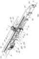
도 6은 본 발명의 일 실시 예에 따른 혈관중재시술로봇을 나타낸 사시도이다.
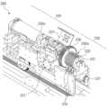
도 7은 본 발명의 일 실시 예에 따른 혈관중재시술로봇을 나타낸 사시도로, 멀티 파트 셋업 지그가 생략된 모습을 나타낸 사시도이다.
도 8은 본 발명의 일 실시 예에 따른 혈관중재시술로봇에서, 가이드와이어의 선단이 상기 초기 세팅 위치로 복귀 시, 도관, 가이드와이어 및 마이크로 도관의 배치 상태를 나타낸 도면이다.
도 9는 본 발명의 일 실시 예에 따른 혈관중재시술로봇의 가이드와이어 구동부를 나타낸 사시도이다.
도 10은 본 발명의 일 실시 예에 따른 가이드와이어 구동부의 병진 모듈 파트를 나타낸 일측면도이다.
도 11 및 도 12는 본 발명의 일 실시 예에 따른 가이드와이어 구동부의 회전 모듈 파트를 나타낸 모식도들이다.
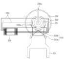
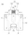
도 13 내지 도 16은 본 발명의 일 실시 예에 따른 멀티 파트 셋업 지그를 설명하기 위한 도면들이다.
도 17은 본 발명의 일 실시 예에 따른 혈관중재시술로봇의 구동 방법을 차례로 나타낸 흐름도이다.
도 18 내지 도 24는 도 17의 각 단계들을 설명하기 위한 참고도들이다.Figure 1 is a schematic diagram showing liver cancer and the nutrient supply hepatic artery.
Figure 2 is a photograph showing the conduit (left) and microconduit-guide wire assembly (right) used in the TACE procedure.
Figure 3 is a schematic diagram of the procedure showing a state in which an insertion conduit with a diameter of 6-7F on the outside and a rotatable guide wire with a diameter of 3-4F on the inside of the insertion conduit are inserted.
Figure 4 is a photograph showing an example of hepatic artery chemoembolization.
Figure 5 is a diagram for explaining a vascular intervention system using a vascular intervention robot according to an embodiment of the present invention.
Figure 6 is a perspective view showing a vascular intervention robot according to an embodiment of the present invention.
Figure 7 is a perspective view showing a vascular interventional robot according to an embodiment of the present invention, with the multi-part setup jig omitted.
Figure 8 is a diagram showing the arrangement state of the conduit, guide wire, and micro conduit when the tip of the guide wire returns to the initial setting position in the vascular intervention robot according to an embodiment of the present invention.
Figure 9 is a perspective view showing the guide wire driving part of the vascular intervention robot according to an embodiment of the present invention.
Figure 10 is a side view showing the translation module part of the guide wire drive unit according to an embodiment of the present invention.
11 and 12 are schematic diagrams showing rotation module parts of a guide wire drive unit according to an embodiment of the present invention.
13 to 16 are diagrams for explaining a multi-part setup jig according to an embodiment of the present invention.
Figure 17 is a flowchart sequentially showing a method of driving a vascular intervention robot according to an embodiment of the present invention.
Figures 18 to 24 are reference diagrams for explaining each step of Figure 17.
이하, 첨부된 도면들을 참조하여 본 발명의 바람직한 실시 예를 상세히 설명할 것이다. 그러나 본 발명의 기술적 사상은 여기서 설명되는 실시 예에 한정되지 않고 다른 형태로 구체화 될 수도 있다. 오히려, 여기서 소개되는 실시 예는 개시된 내용이 철저하고 완전해질 수 있도록 그리고 당업자에게 본 발명의 사상이 충분히 전달될 수 있도록 하기 위해 제공되는 것이다.Hereinafter, preferred embodiments of the present invention will be described in detail with reference to the attached drawings. However, the technical idea of the present invention is not limited to the embodiments described herein and may be embodied in other forms. Rather, the embodiments introduced herein are provided so that the disclosed content will be thorough and complete and so that the spirit of the invention can be sufficiently conveyed to those skilled in the art.
본 명세서에서, 어떤 구성요소가 다른 구성요소 상에 있다고 언급되는 경우에 그것은 다른 구성요소 상에 직접 형성될 수 있거나 또는 그들 사이에 제 3의 구성요소가 개재될 수도 있다는 것을 의미한다. 또한, 도면들에 있어서, 형상 및 크기는 기술적 내용의 효과적인 설명을 위해 과장된 것이다.In this specification, when an element is referred to as being on another element, it means that it may be formed directly on the other element or that a third element may be interposed between them. Additionally, in the drawings, the shape and size are exaggerated for effective explanation of technical content.
또한, 본 명세서의 다양한 실시 예 들에서 제1, 제2, 제3 등의 용어가 다양한 구성요소들을 기술하기 위해서 사용되었지만, 이들 구성요소들이 이 같은 용어들에 의해서 한정되어서는 안 된다. 이들 용어들은 단지 어느 구성요소를 다른 구성요소와 구별시키기 위해서 사용되었을 뿐이다. 따라서, 어느 한 실시 예에 제 1 구성요소로 언급된 것이 다른 실시 예에서는 제 2 구성요소로 언급될 수도 있다. 여기에 설명되고 예시되는 각 실시 예는 그것의 상보적인 실시 예도 포함한다. 또한, 본 명세서에서 '및/또는'은 전후에 나열한 구성요소들 중 적어도 하나를 포함하는 의미로 사용되었다.Additionally, in various embodiments of the present specification, terms such as first, second, and third are used to describe various components, but these components should not be limited by these terms. These terms are merely used to distinguish one component from another. Accordingly, what is referred to as a first component in one embodiment may be referred to as a second component in another embodiment. Each embodiment described and illustrated herein also includes its complementary embodiment. Additionally, in this specification, 'and/or' is used to mean including at least one of the components listed before and after.
명세서에서 단수의 표현은 문맥상 명백하게 다르게 뜻하지 않는 한 복수의 표현을 포함한다. 또한, "포함하다" 또는 "가지다" 등의 용어는 명세서 상에 기재된 특징, 숫자, 단계, 구성요소 또는 이들을 조합한 것이 존재함을 지정하려는 것이지, 하나 또는 그 이상의 다른 특징이나 숫자, 단계, 구성요소 또는 이들을 조합한 것들의 존재 또는 부가 가능성을 배제하는 것으로 이해되어서는 안 된다. 또한, 본 명세서에서 "연결"은 복수의 구성 요소를 간접적으로 연결하는 것, 및 직접적으로 연결하는 것을 모두 포함하는 의미로 사용된다.In the specification, singular expressions include plural expressions unless the context clearly dictates otherwise. In addition, terms such as “include” or “have” are intended to designate the presence of features, numbers, steps, components, or a combination thereof described in the specification, but are not intended to indicate the presence of one or more other features, numbers, steps, or components. It should not be understood as excluding the possibility of the presence or addition of elements or combinations thereof. Additionally, in this specification, “connection” is used to mean both indirectly connecting and directly connecting a plurality of components.
또한, 하기에서 본 발명을 설명함에 있어 관련된 공지 기능 또는 구성에 대한 구체적인 설명이 본 발명의 요지를 불필요하게 흐릴 수 있다고 판단되는 경우에는 그 상세한 설명은 생략할 것이다.Additionally, in the following description of the present invention, if it is determined that a detailed description of a related known function or configuration may unnecessarily obscure the gist of the present invention, the detailed description will be omitted.
도 5 내지 도 16은 본 발명의 일 실시 예에 따른 혈관중재시술로봇을 설명하기 위한 도면들이다.Figures 5 to 16 are drawings for explaining a vascular intervention robot according to an embodiment of the present invention.
도 5에 도시된 바와 같이, 본 발명의 일 실시 예에 따른 혈관중재시술로봇(1000)은 마스터-슬래이브 장비를 기반으로 하는 원격 시술 시스템으로 이루어진 혈관중재시술시스템에 적용될 수 있다. 여기서, 혈관중재시술시스템에서는 마스터 장비 측에서 시술자가 시술을 원격으로 제어하고, 원격 제어에 따라 슬래이브 장비가 환자에 대하여 시술을 진행하게 된다. 이에 따라, 시술자가 방사선에 피폭되는 환경을 최소화할 수 있다.As shown in FIG. 5, the
먼저, 혈관중재시술시스템에 대해 간략히 설명하면, 혈관중재시술시스템은, 본 발명의 일 실시 예에 따른 혈관중재시술로봇(1000) 외에 베드(1100), 프레임(1200), 마스터 장비(1300)를 더 포함할 수 있다.First, to briefly describe the vascular intervention system, the vascular intervention system includes a
베드(1100)는 환자(1120)가 누운 상태로 시술을 받을 수 있도록, 환자가 누울 수 있는 시술면을 제공한다. 이때, 베드(1100)에는 프레임(1200)이 이동 가능하도록 부착될 수 있다. 프레임(1200)의 일측은 혈관중재시술로봇(1000)을 수용 및 고정할 수 있다.The
예를 들어, 프레임(1200)의 상측에는 혈관중재시술로봇(1000)이 장착될 수 있다. 이때, 혈관중재시술로봇(1000)은 프레임(1200)에 대하여 회전 또는 병진 운동할 수 있도록 장착될 수 있다. 프레임(1200)의 타측은 베드(1100)에 이동 가능하도록 부착될 수 있다.For example, a
예를 들어, 프레임(1200)의 타측은 베드(1100)의 레일에 이동 가능하도록 부착될 수 있다. 이와 같이, 혈관중재시술로봇(1000)이 프레임(1200)에 대하여 회전 및 병진 운동할 수 있도록 구비됨으로써, 시술의 편의성이 향상될 수 있다.For example, the other side of the
한편, 마스터 장비(1300)는 시술자(1110)가 혈관중재시술로봇(1000)을 원격 제어할 수 있는 인터페이스를 제공할 수 있다. 이와 같이, 시술자(1110)가 원격으로 혈관중재시술로봇(1000)을 제어함으로써, 시술자의 방사선 피폭을 최소화할 수 있다.Meanwhile, the
도 6 내지 도 8에 도시된 바와 같이, 이러한 혈관중재시술시스템에 적용되는 본 발명의 일 실시 예에 따른 혈관중재시술로봇(1000)은, 베이스 파트, 구동 파트 및 멀티 파트 셋업 지그(700)를 포함할 수 있다.As shown in FIGS. 6 to 8, the
이때, 본 발명의 일 실시 예에 따른 혈관중재시술로봇(1000)은 시술용 와이어의 종류에 따라, 도관 구동부(100), 가이드와이어 구동부(200), 마이크로 도관 구동부(300) 및 마이크로 가이드와이어 구동부(400)를 포함할 수 있다.At this time, the
또한, 본 발명의 일 실시 예에 따른 혈관중재시술로봇(1000)은 부가적으로, 이송부(500) 및 도관 가이드부(600)를 더 포함할 수 있다.In addition, the
본 발명의 일 실시 예에 따르면, 상기 구동 파트는 상기 도관 구동부(100), 가이드와이어 구동부(200), 마이크로 도관 구동부(300) 및 마이크로 가이드와이어 구동부(400) 각각에 구비되어 해당 시술용 와이어를 동작시킬 수 있다.According to one embodiment of the present invention, the driving part is provided in each of the
이때, 본 발명의 일 실시 예에 따르면, 상기 멀티 파트 셋업 지그(700)는 가이드와이어 구동부(200) 및 마이크로 가이드와이어 구동부(400)에 구비되는 구동 파트들에 장착될 수 있는데, 이에 대해서는 하기에서 보다 상세히 설명하기로 한다.At this time, according to an embodiment of the present invention, the
도관 구동부(100)는 길이 방향으로 연장되는 도관(20)을 길이 방향을 축으로 회전 및 병진 운동시킬 수 있다. 이를 통해, 도관 구동부(100)는 도관(20)을 목표 혈관까지 삽입시킬 수 있다. 도관 구동부(100)는 도관(20)을 파지한 상태에서 도관을 회전시킬 수 있다.The
예를 들어, 도관 구동부(100)는 도관(20)이 혈관의 굴곡진 부위와 만났을 때, 그 선단의 방향 전환을 위하여, 도관(20)의 길이 방향을 축으로 도관(20)을 회전시킬 수 있다. 이를 위해, 도관 구동부(100)는 도관 회전 구동체(110) 및 기어(115)를 포함할 수 있다.For example, when the
도관 회전 구동체(110)는 도관(20)을 회전시키는 회전 구동력을 제공하는 장치로서, 예컨대, 모터로 구비될 수 있다.The
기어(115)는 도관 회전 구동체(110)로부터 회전 구동력을 전달 받아 도관(20)을 회전시키는 회전력을 제공할 수 있다. 이때, 기어(115)에는 도관(20)이 기어(115)의 축 방향으로 로딩될 수 있는 슬릿이 구비될 수 있다.The
도 8을 참조하면, 도관 구동부(100)는 제1 Y형 커넥터(120)를 더 포함할 수 있다. 제1 Y형 커넥터(120)는 도관(20)과 가이드와이어(10) 및 도관(20)과 마이크로 도관(40)의 연결 통로를 제공한다.Referring to FIG. 8, the
이를 위하여, 제1 Y형 커넥터(120)는 본체(123) 및 가지부(125)를 포함할 수 있다.To this end, the first Y-
본체(123)는, 내부가 중공을 가지는 관형의 형상을 가질 수 있다. 본체(123)의 길이 방향 일측 단부는 도관(20)이 인입되어 파지될 수 있도록 개구될 수 있다.The
또한, 본체(123)의 길이 방향 타측 단부는 마이크로 도관 구동부(300)와 연결될 수 있다. 이에 따라, 본체(123)의 길이 방향 타측 단부에는 마이크로 도관(40)의 길이 방향 선단이 위치될 수 있다.Additionally, the other longitudinal end of the
하지만, 본 발명의 일 실시 예에 따르면, 목표 혈관에 도관(20)과 가이드와이어(10)를 삽입하기 위한 초기 세팅 시에는 마이크로 도관(40)이 마이크로 도관 구동부(300)에 장착되지 않는다. 이에 따라, 초기 세팅 시 본체(123)의 길이 방향 타측 단부에는 마이크로 도관(40)의 길이 방향 선단이 위치되지 않는다.However, according to one embodiment of the present invention, the
가지부(125)는 본체(123)와 마찬가지로, 내부가 중공을 가지는 관형의 형상을 가질 수 있다. 가지부(125)는 본체(123)의 길이 방향 일측으로부터 분기되어 형성될 수 있다. 이때, 가지부(125)의 중공은 본체(123)의 중공과 연통될 수 있다.Like the
본 발명의 일 실시 예에서, 이러한 가지부(125)의 길이 방향 단부에는 가이드와이어(10)를 회전 및 병진 운동시키는 가이드와이어 구동부(200)가 연결될 수 있다.In one embodiment of the present invention, a guide
목표 혈관에 도관(20)과 가이드와이어(10)를 삽입하기 위한 초기 세팅 시, 도관(20)의 길이 방향 후단은 본체(123)의 길이 방향 일측 단부에 인입 및 파지되고, 가이드와이어(10)의 선단은 가지부(125)의 분기점 측에 배치될 수 있다.During the initial setting for inserting the
이후, 혈관중재시술로봇(1000)이 작동되어, 가이드와이어(10) 및 도관(20)이 목표 혈관까지 삽입되면, 가이드와이어(10)는 후진되고, 그 선단은 초기 세팅 위치로 복귀하게 된다. 이와 같이, 가이드와이어(10)의 선단이 초기 세팅 위치로 복귀하면, 마이크로 도관 구동부(300)에 마이크로 도관(40)이 장착될 수 있다. 이에 따라, 본체(123)의 길이 방향 타단에는 마이크로 도관(40)의 선단이 위치하게 된다.Thereafter, when the
이로 인해, 마이크로 도관(40)이 도관(20) 내측으로 인입되는 경우, 도관(20)에 대한 가이드와이어(10)의 인입 및 인출 경로와 다른 경로로 마이크로 도관(40)이 인입 및 인출될 수 있다.For this reason, when the
본 발명의 일 실시 예에 따르면, 마이크로 도관(40)은 도관(20)과 동축으로 인입 및 인출될 수 있다. 이에 따라, 마이크로 도관(40)을 도관(20) 내측으로 인입시키는 경우, 가이드와이어(10)의 인입 및 인출에 간섭 받지 않게 되며, 그 결과, 혈관중재시술의 편의성을 향상시킬 수 있고, 시술 시간을 단축시킬 수 있게 된다.According to one embodiment of the present invention, the
이러한 제1 Y형 커넥터(120)는 케이스(133)에 안착될 수 있다. 케이스(133)의 상측에는 덮개(135)가 결합될 수 있다.This first Y-
덮개(135)는 제1 Y형 커넥터(120)를 덮으면서 케이스(133)와 결합될 수 있다. 이러한 케이스(133)와 덮개(135)는 제1 Y형 커넥터(120)를 외부 환경으로부터 보호하는 역할을 한다.The
한편, 도관 구동부(100)는 도관(20)이 목표 혈관까지 삽입되도록 도관(20)을 병진 운동시킬 수 있다. 이를 위해, 도관 구동부(100)는 도관 병진 구동체(150)를 더 포함할 수 있다.Meanwhile, the
도관 병진 구동체(150)는 이송부(500)에 구비되는 랙(550)과 피니언(560)에 구동력을 제공하며, 이러한 랙(550)과 피니언(560) 조립체에 탑재되어 있는 도관 구동부(100)를 이동시키게 된다. 도관(20)은 이러한 도관 구동부(100)의 이동을 통해 병진 운동하게 된다.The conduit
도 9 및 도 10에 도시된 바와 같이, 본 발명의 일 실시 예에 따르면, 가이드와이어 구동부(200)는 도관 구동부(100)의 측방에 구비될 수 있다. 가이드와이어 구동부(200)는 가이드와이어(10)를 병진 운동시켜, 가이드와이어(10)를 도관(20) 내측으로 인입 및 목표 혈관 근처까지 삽입시키고, 가이드와이어(10)를 도관(20)과 동축으로 회전시킨다.As shown in FIGS. 9 and 10, according to an embodiment of the present invention, the guide
이러한 가이드와이어 구동부(200)는 제1 Y형 커넥터(120)의 가지부(125)에 연결된다. 이를 위해, 가이드와이어 구동부(200)는 연결수단으로, 제1 Y형 커넥터(120)의 가지부(125)에 결합되는 제2 Y형 커넥터(210)를 구비할 수 있다.This guide
제2 Y형 커넥터(210)는 제1 Y형 커넥터(120)와 동일한 구조로 이루어질 수 있다.The second Y-
이에 따라, 가이드와이어 구동부(200)는 제2 Y형 커넥터(210) 및 제1 Y형 커넥터(120)의 가지부(125)를 통하여, 본체(123)의 길이 방향 일측 단부에 인입 및 파지되어 있는 도관(20) 내측으로 가이드와이어(10)를 제공할 수 있다.Accordingly, the guide
이러한 가이드와이어 구동부(200)는 시술용 와이어 중 하나인 가이드 와이어(10)를 동작시키기 위하여 세트를 이루는 복수 개의 구동 파트를 구비할 수 있다.This guide
상기 복수 개의 구동 파트는 가이드와이어(10)를 병진시키는 병진 모듈 파트(220) 및 가이드와이어(10)를 축 회전시키기 위하여 병진 모듈 파트(220)를 회전시키는 회전 모듈 파트(230)를 포함할 수 있다.The plurality of driving parts may include a
병진 모듈 파트(220)는 하우징(220a), 병진 모터(221), 구동 롤러(222) 및 가이드 롤러(223)를 포함할 수 있다.The
하우징(220a)은 병진 모듈 파트(220)의 외관을 이룬다. 하우징(220a)은, 병진 모터(221), 구동 롤러(222) 및 가이드 롤러(223)가 내부에 장착될 수 있도록 이들의 장착 공간을 제공하며, 이들을 외부 환경으로부터 보호한다. 이때, 구동 롤러(222) 및 가이드 롤러(223)가 장착되는 하우징(220a)의 내부 공간과, 병진 모터(221)가 장착되는 하우징(220a)의 내부 공간은 공간적으로 분리될 수 있다.The
한편, 하우징(220a)의 상단에는 이의 내부 공간을 개폐시키는 경첩 커버(227)가 설치될 수 있다.Meanwhile, a
병진 모터(221)는 하우징(220a)의 내부 공간 일측에 장착될 수 있다. 병진 모터(221)는 구동 롤러(222)의 하측에 배치될 수 있다. 이러한 병진 모터(221)는 가이드와이어(10)를 병진시키기 위한 병진 구동력을 구동 롤러(222)에 제공할 수 있다. 이러한 병진 모터(221)는 병진 모터 드라이버(도 12의 224)로부터 병진 구동력을 제공 받으며, 이를 위해, 병진 모터(221)는 복수 개의 전기 라인(도 12의 225)을 통하여, 병진 모터 드라이버(도 12의 224)와 전기적으로 연결될 수 있다.The
구동 롤러(222)는 병진 모터(221)로부터 병진 구동력을 제공받아 회전할 수 있다. 구동 롤러(222)는 가이드와이어(10)의 하측과 구름 접촉될 수 있다. 이에 따라, 구동 롤러(222)의 회전 시 가이드와이어(10)는 구동 롤러(222)에 의해 병진 운동할 수 있다.The driving
구동 롤러(222)는 복수 개로 구비될 수 있다. 복수 개의 구동 롤러(222)는 일 방향, 예컨대, 가이드와이어(10)의 이송 방향을 따라 배열될 수 있다. 이에 따라, 가이드와이어(10)는 일 방향으로 배열되어 있는 구동 롤러(222)에 구름 접촉하면서 이동되어, 제2 Y형 커넥터(210) 측으로 인입될 수 있다.There may be a plurality of driving
가이드 롤러(223)는 복수 개로 구비될 수 있다. 이러한 복수 개의 가이드 롤러(223)는 복수 개의 구동 롤러(222) 상에 배치될 수 있다. 이때, 복수 개의 가이드 롤러(223) 각각은 복수 개의 구동 롤러(222) 각각과 대응되게 배치되어 구동 롤러(222)에 대하여 상대 회전하면서 가이드와이어(10)의 병진 운동을 가이드할 수 있다.There may be a plurality of
즉, 가이드와이어(10)는 이와 같이 상하 방향으로 배치되는 구동 롤러(222)와 가이드 롤러(223) 사이를 이들과 구름 접촉하면서 통과하게 된다.That is, the
회전 모듈 파트(230)는 가이드와이어(10)를 축 회전시킨다. 이를 위해, 회전 모듈 파트(230)는 병진 모듈 파트(220)를 회전시킨다. 즉, 병진 모듈 파트(220)는 회전 모듈 파트(230)에 의해 회전하게 되고, 이러한 병진 모듈 파트(220)의 회전에 의해 가이드와이어(10)가 축 회전하게 된다.The
이때, 본 발명의 일 실시 예에 따르면, 구동 롤러(222)와 가이드 롤러(223) 사이에 위치하는 가이드와이어(10)가 이들과 선 접촉을 이루게 됨에 따라, 회전 모듈 파트(230)에 의한 병진 모듈 파트(220)의 회전에 따른 가이드와이어(10)의 축 회전 시, 구동 롤러(222) 상에서 가이드와이어(10)가 슬립되는 현상이 최소화될 수 있다.At this time, according to an embodiment of the present invention, as the
즉, 본 발명의 일 실시 예에 따르면, 구동 롤러(222)와 가이드 롤러(223) 사이에 위치하는 가이드와이어(10)가 이들과 선 접촉을 이룸으로써, 회전 및 병진 운동하는 가이드와이어(10)의 슬립이 최소화될 수 있다.That is, according to one embodiment of the present invention, the
상기 회전 모듈 파트(230)는 회전 모터(237) 및 회전 기어(236)를 포함할 수 있다. 회전 모터(237)는 가이드와이어(10)를 축 회전시키기 위한 구동력을 제공할 수 있다. 회전 기어(236)는 회전 모터(237)로부터 구동력을 전달 받는다.The
이를 위해, 회전 기어(236)는 회전 모터(237)의 회전축에 축 결합될 수 있다. 회전 기어(236)는 병진 모듈 파트(220)와 동축 연결되고, 이에 따라, 회전 모터(237)로부터 제공되는 회전 구동력은 회전 기어(236)를 통해 병진 모듈 파트(220)에 전달될 수 있다.To this end, the
한편, 회전 기어(236)에는 슬릿이 형성될 수 있다. 이러한 슬릿은 후술되는 적어도 하나의 접속판(231)의 슬릿(230a)과 원주 방향으로 동일한 위치에 형성될 수 있다.Meanwhile, a slit may be formed in the
이에 따라, 회전 기어(236)의 슬릿과, 적어도 하나의 접속판(231)의 슬릿(230a)들은 일 방향으로 연통되는 트렌치를 이루게 되고, 이러한 트렌치에는 가이드와이어(10)가 길이 방향으로 로딩될 수 있다.Accordingly, the slit of the
여기서, 회전 모듈 파트(230)에 의해 병진 모듈 파트(220)가 회전되는 경우, 병진 모터(221) 또한 회전하게 된다. 이와 같이, 병진 모터(221)가 회전하게 되면, 병진 모터(221)와 병진 모터 드라이버(도 12의 224) 사이를 전기적으로 연결하는 복수 개의 전기 라인(도 12의 225)이 꼬일 수 있다.Here, when the
이러한 꼬임 현상이 계속될 경우, 전기 라인(도 12의 225) 중 일부 혹은 전부가 병진 모터(221)로부터 분리되어, 시술 중 혈관중재시술로봇(1000) 작동을 멈춰야 하는 비상 상황이 발생될 수 있다.If this twisting phenomenon continues, some or all of the electric lines (225 in FIG. 12) may be separated from the
도 11 및 도 12를 더 참조하면, 이러한 문제를 해결하기 위해, 즉, 전기 라인(225)에 대한 경로를 제공하기 위하여, 본 발명의 일 실시 예에 따른 회전 모듈 파트(230)는 접속판(231)을 포함할 수 있다.Referring further to FIGS. 11 and 12, in order to solve this problem, that is, to provide a path for the
접속판(231)은 회전 기어(236)의 후방에 배치될 수 있다. 접속판(231)은 회전 기어(236)와 직결될 수 있다. 이에 따라, 접속판(231)은 회전 기어(236)의 회전에 연동될 수 있다.The
이러한 접속판(231)은 병진 모터(221)와 병진 모터 드라이버(224) 사이를 전기적으로 연결하는 복수 개의 전기 라인(225)에 대응되는 개수로 구비될 수 있다. 즉, 각각의 접속판(231)은 복수 개의 전기 라인(225) 중 어느 하나와 대응될 수 있다.These
이러한 복수 개의 접속판(231)은 회전 기어(236)의 후방에서 일 방향, 예컨대, 가이드와이어(10)의 길이 방향으로 배열될 수 있다.These plurality of
이때, 접속판(231) 각각에는 회전 모듈 파트(230)에 의한 병진 모듈 파트(220)의 회전 축 방향으로 가이드와이어(10)를 사용하도록 중심 방향으로 개구된 슬릿(230a)이 형성될 수 있다. 전술한 바와 같이, 이들 슬릿(230a)은 회전 기어(236)의 슬릿과 연결되어 단일 트렌치 구조를 이루게 된다.At this time, a
접속판(231)에는 접속링(232)이 배치될 수 있다. 이러한 접속링(232)은 상기 슬릿(230a)에 의하여 원주 방향으로 일측이 오픈되어 있는 환형 띠 형상으로 구비될 수 있다.A
이러한 접속판(231)에는 복수 개의 전기 라인(225)과 대응되는 개수의 전기 라인 접속부(232a)가 형성될 수 있다. 전기 라인 접속부(232a)는 접속판(231)의 원주 방향으로 형성될 수 있다.A plurality of
하나의 접속판(231)을 기준으로 보면, 복수 개의 전기 라인 접속부(232a) 중 어느 하나에는 특정한 하나의 전기 라인(225)이 연결되어 해당 접속판(231)에 구비되어 있는 접속링(232)에 접속될 수 있다.Based on one
이에 따라, 일 방향으로 배열되는 복수 개의 접속판(231)을 정면에서 봤을 때, 각각의 전기 라인(225)은 서로 중첩되지 않고 원주 방향으로 이격된 상태로 해당 접속링(232)에 접속될 수 있다.Accordingly, when the plurality of
한편, 본 발명의 일 실시 예에 따른 회전 모듈 파트(230)는 다중 접점 플레이트(233)를 더 포함할 수 있다.Meanwhile, the
다중 접점 플레이트(233)는 접속링(232)과 병진 모터 드라이버(224)를 전기적으로 연결하도록 접속링(232) 표면에 원주 방향으로 서로 다른 위치에 적어도 2개의 접점을 가질 수 있다.The
이에 따라, 접속판(231)의 회전 시 슬릿(230a)에 의해 어느 하나의 접점이 단절되더라도 다른 접점은 계속 유지되므로, 접속링(232)과 병진 모터 드라이버(224) 간의 전기적 연결 상태는 계속적으로 유지될 수 있다.Accordingly, even if one contact point is cut off by the
본 발명의 일 실시 예에 따르면, 이러한 다중 접점 플레이트(233)는 복수 개로 구비될 수 있다. 복수 개의 다중 접점 플레이트(233)는 복수 개의 접속링(232) 각각에 접속될 수 있다. 이에 따라, 복수 개의 다중 접점 플레이트(233) 또한 복수 개의 접속링(232) 배열 방향과 동일한 방향으로 배열될 수 있다.According to one embodiment of the present invention, a plurality of such
이때, 본 발명의 일 실시 예에 따르면, 일 방향으로 배열되는 복수 개의 다중 접점 플레이트(233) 간의 간섭을 방지하기 위해, 복수 개의 다중 접점 플레이트(233)는 일 방향으로 교차 배열될 수 있다.At this time, according to one embodiment of the present invention, in order to prevent interference between the plurality of
예를 들어, 회전 기어(236)를 기준으로, 홀수 번째 배치되는 다중 접점 플레이트(233)들은 접속링(232)의 좌측 하단(도 11 기준)에 배치될 수 있고, 짝수 번째 배치되는 다중 접점 플레이트(233)들은 우측 하단(도 11 기준)에 배치될 수 있다.For example, based on the
본 발명의 일 실시 예에 따른 다중 접점 플레이트(233)는 접속링(232)에 대하여 2 개의 접점을 가질 수 있다.The
이러한 다중 접점 플레이트(233)는 전도성을 갖는 금속 재질로 이루어지며, 본체부(233a) 및 가지부(233b)를 포함할 수 있다.This
본체부(233a)는 일 방향으로 연장되는 판상으로 구비될 수 있다. 가지부(233b)는 본체부(233a)의 길이 방향 일측 단부로부터 두 갈래로 분기될 수 있다.The
이와 같이, 두 갈래로 분기된 가지부(233b)의 길이 방향 일측 단부는 접속링(232)의 표면에 각각 접촉될 수 있다. 즉, 두 갈래로 분기된 가지부(233b)는 접속링(232)의 표면에 원주 방향으로 다른 위치에 접촉될 수 있다.In this way, one longitudinal end of the
여기서, 가지부(233b)가 두 갈래로 분기되는 것은 하나의 예시일 뿐, 그 이상의 갈래로 분기되어 접속링(232)의 표면 여러 위치에 접촉될 수 있음은 물론이다.Here, the fact that the
한편, 본 발명의 일 실시 예에 따른 회전 모듈 파트(230)는 베이스부(234) 및 전원 공급부(235)를 더 포함할 수 있다.Meanwhile, the
베이스부(234)는 다중 접점 플레이트(233)를 지지한다. 구체적으로, 베이스부(234)에는 다중 접점 플레이트(233)의 본체부(233a)가 결합되어 고정될 수 있다. 이에 따라, 다중 접점 플레이트(233)의 가지부(233b)는 접속링(232)과의 안정적인 접점을 유지할 수 있다.The
전원 공급부(235)는 베이스부(234)에 장착될 수 있다. 전원 공급부(235)는 다중 접점 플레이트(233)와 전기적으로 연결될 수 있다. 이에 따라, 전원 공급부(235)는 다중 접점 플레이트(233), 접속링(232) 및 전기 라인(225)을 통해 병진 모터(221) 및 병진 모터 드라이버(224)에 전원을 공급할 수 있다.The
목표 혈관에 도관(20)과 가이드와이어(10)를 삽입하기 위한 초기 세팅 시, 가이드와이어(10)는 병진 모듈 파트(220)에 의해, 그 선단이 제1 Y형 커넥터(120)를 이루는 가지부(125)의 분기점 측에 배치될 수 있다.During the initial setting for inserting the
또한, 가이드와이어(10)는 병진 모듈 파트(220)에 의해 도관(20) 내측으로 인입되고, 계속되는 병진 운동을 통해 목표 혈관 근처까지 삽입될 수 있다. 이때, 가이드와이어(10)는 병진 운동 과정에서 혈관의 굴곡진 부위를 만났을 때, 회전 모듈 파트(230)에 의해 회전될 수 있고, 이를 통해, 그 선단의 방향이 전환되어 다시 원활하게 병진 운동을 할 수 있게 된다.Additionally, the
또한, 목표 혈관에 대한 도관(20)의 삽입 완료 시, 가이드와이어(10)는 병진 모듈 파트(220)에 의해, 후진되어, 그 선단이 초기 세팅 위치로 복귀하게 된다.Additionally, upon completion of insertion of the
본 발명의 일 실시 예에 따르면, 전술한 병진 모듈 파트(220)와 회전 모듈 파트(230)는 멀티 파트 셋업 지그(700)에 의해 동축 정렬되고, 일체로 고정된 상태로, 베이스 파트(도 13의 501)에 한번에 조립되는데, 이에 대해서는 하기에서 보다 상세히 설명하기 한다.According to one embodiment of the present invention, the above-described
한편, 다시 도 7 및 도 8을 참조하면, 마이크로 도관 구동부(300)는, 도관 구동부(100)의 후방에 구비될 수 있다.Meanwhile, referring again to FIGS. 7 and 8, the micro
마이크로 도관 구동부(300)는 가이드와이어(10)가 도관(20) 내측으로부터 인출되어, 초기 세팅 위치로 복귀되었을 때, 가이드와이어(10)의 인입 및 인출 경로와 다른 경로, 즉, 도관(20)과 동축 경로로 마이크로 도관(40)을 인입시켜, 마이크로 도관(40)을 병진 운동시키게 된다.When the
본 발명의 일 실시 예에 따른 마이크로 도관 구동부(300)는 선단 장착부(300A) 및 후단 장착부(300B)를 포함하여 형성될 수 있다.The micro
선단 장착부(300A)는 도관 구동부(100) 측에 직접 연결될 수 있다. 선단 장착부(300A)에는 마이크로 도관(40)의 길이 방향 선단 부분이 장착될 수 있다. 이러한 선단 장착부(300A)는 마이크로 도관(40)을 회전 및 병진시키기 위한 구동 파트들을 구비할 수 있다.The
이때, 상기 구동 파트들의 세부 구성 및 작용은 가이드와이어 구동부(200)에 적용되는 병진 모듈 파트(220) 및 회전 모듈 파트(230)의 세부 구성 및 작용과 동일 또는 유사하므로, 이들에 대한 상세한 설명은 생략하기로 한다.At this time, the detailed configuration and operation of the driving parts are the same or similar to those of the
목표 혈관에 도관(20)과 가이드와이어(10)를 삽입하기 위한 초기 세팅 시에는 선단 장착부(300A)가 도관 구동부(100)에 직접 연결되어 있는 관계로, 도관 구동부(100)의 이동 시 선단 장착부(300A)가 함께 이동하게 된다.During the initial setting for inserting the
이때, 목표 혈관에 도관(20)과 가이드와이어(10)를 삽입하기 위한 초기 세팅 시, 선단 장착부(300A)에는 마이크로 도관(40)의 길이 방향 선단이 미장착되어 있다.At this time, during the initial setting for inserting the
목표 혈관에 대한 도관(20)의 삽입이 완료되고, 가이드와이어(10)의 선단이 초기 세팅 위치로 복귀된 상태일 때, 마이크로 도관(40)의 길이 방향 선단이 선단 장착부(300A)에 장착될 수 있다.When the insertion of the
후단 장착부(300B)는 선단 장착부(300A)의 후방으로 이격된다. 후단 장착부(300B)는 목표 혈관에 도관(20)과 가이드와이어(10)를 삽입하기 위한 초기 세팅 시 도관 구동부(100)의 이동에 의해 선단 장착부(300A)가 이동될 때, 이에 연동되지 않고 정 위치 상태를 유지할 수 있다. 후단 장착부(300B)는 마이크로 가이드와이어 구동부(400)와 연결될 수 있다.The rear
이러한 후단 장착부(300B)에는 마이크로 도관(40)의 후단이 장착된다. 후단 장착부(300B)는 마이크로 도관(40)의 후단 장착을 위해, 제3 Y형 커넥터(도 18의 330)를 구비할 수 있다. 제3 Y형 커넥터(330)는 제1 및 제2 Y형 커넥터(120, 210)와 동일한 구조로 형성될 수 있다.The rear end of the
제3 Y형 커넥터(330)는 길이 방향 타측 단부에 위치하게 되는 마이크로 가이드와이어(30)가 길이 방향 일측 단부에 장착되는 마이크로 도관(40) 내측으로 삽입될 수 있는 연결 통로를 제공하는 역할을 한다.The third Y-
목표 혈관에 대한 도관(20)의 삽입이 완료되고, 가이드와이어(10)의 선단이 초기 세팅 위치로 복귀된 후, 목표 미세 혈관으로 마이크로 도관(40) 및 마이크로 가이드와이어(30)를 삽입하기 위해, 마이크로 도관 구동부(300)에 마이크로 도관(40)을 장착하는 세팅 시, 마이크로 도관(40)은 먼저, 제1 장력을 갖도록 세팅될 수 있다.After the insertion of the
즉, 도시된 바와 같이, 마이크로 도관(40)은 선단 장착부(300A)와 후단 장착부(300B) 사이에 느슨한 상태로 연결될 수 있다.That is, as shown, the
이 상태에서, 혈관중재시술 진행을 위해, 선단 장착부(300A)에 구비되어 있는 구동 파트는, 길이 방향 후단이 후단 장착부(300B)에 고정되어 있는 마이크로 도관(40)의 선단을 전방으로 병진 운동시키고, 이를 통해, 마이크로 도관(40)을 도관(20) 내측으로 인입시킨다.In this state, in order to proceed with the vascular intervention procedure, the driving part provided in the distal
이에 따라, 혈관중재시술 시, 마이크로 도관(40)은 제1 장력을 가질 때보다 세기가 증가된 제2 장력을 갖게 된다(도 22 참조). 즉, 마이크로 도관(40)은 느슨한 상태에서 팽팽한 상태로 변화될 수 있다.Accordingly, during vascular intervention, the
여기서, 후단 장착부(300B)는 마이크로 도관 병진 구동체(도 18의 340)를 구비할 수 있다. 마이크로 도관 병진 구동체(340)는 후단 장착부(300B)를 이동시키는 동력을 제공하고, 이에 따라, 마이크로 도관(40)은 병진 운동하게 된다. 이때, 이러한 마이크로 도관 병진 구동체(340)는 도관 구동부(100)를 이동시키는 동력을 제공하는 도관 병진 구동체(150)와 동기화될 수 있다.Here, the rear
이에 따라, 혈관중재시술 시, 마이크로 도관(40)을 병진 운동시키기 위해, 마이크로 도관 병진 구동체(340)에 의해 후단 장착부(300B)가 이동되면, 이와 동기화되어 있는 도관 병진 구동체(150)에 의해 도관 구동부(100) 및 이에 연결되어 있는 선단 장착부(300A)가 후단 장착부(300B)와 동일한 속도 및 거리로 이동됨으로써, 마이크로 도관(40)이 갖는 제2 장력이 혈관중재시술 과정에서 계속적으로 유지될 수 있다.Accordingly, when the rear
이때, 마이크로 도관 병진 구동체(340)와 도관 병진 구동체(150)의 동기화를 통해, 도관(20)과 마이크로 도관(40)이 미세 혈관과 만나는 혈관의 끝 부분에 도달하게 되면, 마이크로 도관 병진 구동체(340)와 도관 병진 구동체(150)의 동기화는 해제되고, 마이크로 도관 병진 구동체(340)만이 구동될 수 있다. 이에 따라, 미세 혈관 내측으로는 마이크로 도관(40)만이 계속 병진 운동하게 된다.At this time, through synchronization of the micro
마이크로 가이드와이어 구동부(400)는 마이크로 도관 구동부(300), 보다 상세하게는 후단 장착부(300B)의 후방에 구비될 수 있다. 마이크로 가이드와이어 구동부(400)는 마이크로 가이드와이어(30)를 병진 운동시켜, 마이크로 가이드와이어(30)를 마이크로 도관(40) 내측으로 인입 및 목표 미세 혈관 근처까지 삽입시키고, 마이크로 가이드와이어(30)를 마이크로 도관(40)과 동축으로 회전시킬 수 있다.The micro
이때, 마이크로 가이드와이어 구동부(400)에 장착되는 마이크로 가이드와이어(30)의 선단은 후단 장착부(300B)에 구비되는 제3 Y형 커넥터(330)의 길이 방향 타측 단부에 배치될 수 있다.At this time, the tip of the
이러한 마이크로 가이드와이어 구동부(400)에는 마이크로 가이드와이어(30)를 병진시키는 병진 모듈 파트(420) 및 마이크로 가이드와이어(30)가 축 회전되도록 병진 모듈 파트(420)를 회전시키는 회전 모듈 파트(430)가 구비될 수 있다. 이러한 병진 모듈 파트(420) 및 회전 모듈 파트(430)는 가이드와이어 구동부(200)에 구비되는 병진 모듈 파트(220) 및 회전 모듈 파트(430)와 동일한 기능 및 작용을 하므로, 이들에 대한 상세한 설명은 생략하기로 한다.This micro
목표 미세 혈관으로 마이크로 도관(40) 및 마이크로 가이드와이어(30)를 삽입하기 위한 세팅 시, 마이크로 가이드와이어(30)는 마이크로 가이드와이어 구동부(400)에 장착된다. 마이크로 가이드와이어(30)는 상기 병진 모듈 파트(420)에 의해 병진 운동하여 마이크로 도관(40) 내측으로 인입되고 목표 미세 혈관 근처까지 삽입될 수 있다.When setting up to insert the
또한, 병진 운동하는 마이크로 가이드와이어(30)가 미세 혈관의 굴곡진 부위와 만났을 때, 마이크로 가이드와이어(30)는 상기 회전 모듈 파트(430)에 의해 회전되고 이에 따라, 마이크로 가이드와이어(30)의 선단 방향이 조절될 수 있다. 그 결과, 마이크로 가이드와이어(30)는 계속적으로 목표 미세 혈관을 향해 병진 운동을 할 수 있게 된다.In addition, when the translating
한편, 이송부(500)는 도관 병진 구동체(150) 및 마이크로 도관 병진 구동체(340)로부터 구동력을 제공 받아, 도관 구동부(100) 및 마이크로 도관 구동부(300)를 도관(20)의 길이 방향을 따라 이송시킬 수 있다.Meanwhile, the
이러한 이송부(500)는 베이스부(510), 제1 격벽(520), 제2 격벽(530), 지지봉(540), 랙(rack; 550) 및 피니언(560)을 포함할 수 있다.This
베이스부(510)는 혈관중재시술로봇(1000)의 기저면을 제공하는 프레임일 수 있다. 제1 격벽(520) 및 제2 격벽(530)은 베이스부(510)의 길이 방향 양단에 마련될 수 있다. 지지봉(540)은 제1 격벽(520) 및 제2 격벽(530) 사이에 마련될 수 있다. 랙(550)은 베이스부(510)의 상면에 혈관중재시술로봇(1000)의 길이 방향으로 마련될 수 있다. 피니언(560)은 랙(550)과 기어 결합하며, 도관 병진 구동체(150) 또는 마이크로 도관 병진 구동체(340)로부터 구동력을 전달받아 동작될 수 있다. 이에 따라, 랙(550)과 피니언(560) 조립체에 탑재되어 있는 도관 구동부(100) 및 마이크로 도관 구동부(300)는 혈관중재시술로봇(1000)의 길이 방향으로 이동할 수 있다.The
이때, 피니언(560)은 도관 구동부(100) 및 마이크로 도관 구동부(300)의 개별 이동이 가능하도록, 도관 구동부(100) 및 마이크로 도관 구동부(300) 각각에 연결될 수 있고, 도관 병진 구동체(150) 및 마이크로 도관 병진 구동체(340)는 각각, 도관 구동부(100) 및 마이크로 도관 구동부(300)에 연결되어 있는 피니언(560)에 구동력을 제공할 수 있다.At this time, the
한편, 지지봉(540)은 도관 구동부(100) 및 마이크로 도관 구동부(300)의 이동에 대한 가이드 경로를 제공할 수 있다.Meanwhile, the
도관 가이드부(600)는 도관(20)의 길이 방향으로 절첩하면서 도관(20)을 지지하는 기능을 수행할 수 있다. 도관 가이드부(600)는 일 방향으로 연장되는 관 형태로 구비될 수 있다. 이때, 도관 가이드부(600)는 도관(20)의 삽입 및 이동이 가능하도록, 그 내부는 길이 방향으로 중공이 형성될 수 있으며, 길이 방향 양측 단부는 개구될 수 있다.The
본 발명의 일 실시 예에서, 이러한 도관 가이드부(600)는 절첩을 위하여 텔레스코프 구조(telescope structure)로 이루어질 수 있다.In one embodiment of the present invention, the
도 13에 도시된 바와 같이, 본 발명의 일 실시 예에 따르면, 멀티 파트 셋업 지그(700)는 가이드와이어 구동부(200)에 구비되는 구동 파트들인 병진 모듈 파트(220)와 회전 모듈 파트(230)를 동축 정렬시키고, 하나의 모듈을 이루도록 일체로 고정할 수 있다.As shown in FIG. 13, according to an embodiment of the present invention, the
또한, 도 14에 도시된 바와 같이, 상기 멀티 파트 셋업 지그(700)는 마이크로 가이드와이어 구동부(400)에 구비되는 구동 파트들인 병진 모듈 파트(420)와 회전 모듈 파트(430)를 동축 정렬시키고, 하나의 모듈을 이루도록 일체로 고정할 수 있다.In addition, as shown in FIG. 14, the
본 발명의 일 실시 예에 따른 혈관중재시술로봇(1000)은 이러한 멀티 파트 셋업 지그(700)를 구비함으로써, 병진 모듈 파트(220)와 회전 모듈 파트(230)를 가이드와이어 구동부(200)의 베이스 파트(501)에 조립 시, 상기 베이스 파트(501)에 상기 병진 모듈 파트(220)와 회전 모듈 파트(230)를 한 번에 조립할 수 있고, 병진 모듈 파트(420)와 회전 모듈 파트(430)를 마이크로 가이드와이어 구동부(400)의 베이스 파트(501)에 조립 시, 상기 베이스 파트(501)에 상기 병진 모듈 파트(420)와 회전 모듈 파트(430)를 한 번에 조립할 수 있다.The
이에 따라, 간편하게 혈관중재시술로봇(1000)을 조립할 수 있으며, 조립 후 별도의 얼라인 작업이 요구되지 않아, 조립 시간을 단축시킬 수 있으며, 우수한 조립성 또한 확보할 수 있다.Accordingly, the
여기서, 상기 베이스 파트(501)는 가이드와이어 구동부(200) 및 마이크로 가이드와이어 구동부(400)에서 병진 모듈 파트(220, 420)와 회전 모듈 파트(230, 430)의 장착 공간을 제공하고, 이들을 지지하는 구조물일 수 있다. 이때, 본 발명의 일 실시 예에 따르면, 회전 모듈 파트(230)의 다중 접점 플레이트(233)와 회전 모터(237)는 베이스 파트(501)에 기 장착되어 있을 수 있다. 이에 따라, 멀티 파트 셋업 지그(700)에 의해 일체로 고정되는 병진 모듈 파트(220)와 회전 모듈 파트(230)가 베이스 파트(501)에 조립될 때, 다중 접점 플레이트(233)는 병진 모터(221)와 연결될 수 있고, 회전 모터(237)는 회전 기어(236)와 연결될 수 있다.Here, the
도 13 내지 도 16에 도시된 바와 같이, 본 발명의 일 실시 예에 따르면, 이러한 멀티 파트 셋업 지그(700)는 구동 파트 체결부(710) 및 지그 본체부(720)를 포함할 수 있다.As shown in Figures 13 to 16, according to an embodiment of the present invention, this
상기 구동 파트 체결부(710)는 세트를 이루는 복수 개이 구동 파트인 병진 모듈 파트(220) 및 회전 모듈 파트(230)의 길이 방향 일단과 타단에 구비될 수 있다. 또한, 구동 파트 체결부(710)는 병진 모듈 파트(220)와 회전 모듈 파트(230) 사이에 각각 구비될 수 있다. 즉, 본 발명의 일 실시 예에 따르면, 구동 파트 체결부(710)는 병진 모듈 파트(220)의 길이 방향 선단, 회전 모듈 파트(230)의 길이 방향 후단 및 병진 모듈 파트(220)와 회전 모듈 파트(230) 사이에 구비될 수 있다.The driving
구동 파트 체결부(710)는 이와 같이, 병진 모듈 파트(220)의 길이 방향 선단, 회전 모듈 파트(230)의 길이 방향 후단 및 병진 모듈 파트(220)와 회전 모듈 파트(230) 사이에 구비되어, 병진 모듈 파트(220)와 회전 모듈 파트(230)를 축 방향으로 정렬시킬 수 있다. 이에 따라, 병진 모듈 파트(220)와 회전 모듈 파트(230)를 베이스 파트(501)에 조립한 후 이들의 얼라인을 맞춰야 하는 작업을 생략할 수 있다.As such, the driving
본 발명의 일 실시 예에 따르면, 상기 구동 파트 체결부(710)는, 지그 베이스부(711) 및 체결부(712)를 포함할 수 있다.According to one embodiment of the present invention, the driving
지그 베이스부(711)는 베이스 파트(501)와 결합되는 구동 파트 체결부(710)의 하단 부분일 수 있다.The
체결부(712)는 지그 베이스부(711) 상에 구비될 수 있다. 체결부(712)는 지그 베이스부(711) 상에서 상측으로 돌출될 수 있다. 체결부(712)는 구동 파트인 병진 모듈 파트(220) 및 회전 모듈 파트(230)와 동축 연결될 수 있다. 이러한 체결부(712)에는 시술용 와이어인 가이드와이어(10)가 관통되는 홀(712a)이 형성될 수 있다. 또한, 체결부(712)의 폭 방향으로 마주하는 외주면 양측에는 걸쇠 홈(712b)이 마련될 수 있다. 이러한 걸쇠 홈(712b)에는 후술되는 집게부(721)의 걸쇠(725)가 끼워질 수 있다. 이러한 체결부(712)는 상측으로 결합되는 지그 본체부(720)에 의해 케이싱될 수 있다.The
상기 지그 본체부(720)는 구동 파트 체결부(710)에 결합될 수 있다. 지그 본체부(720)는 병진 모듈 파트(220)의 길이 방향 선단, 회전 모듈 파트(230)의 길이 방향 후단 및 병진 모듈 파트(220)와 회전 모듈 파트(230) 사이에 구비되는 구동 파트 체결부(710)에 각각 결합될 수 있다.The
본 발명의 일 실시 예에 따르면, 이러한 지그 본체부(720)는 집게부(721) 및 케이스부(722)를 포함할 수 있다.According to one embodiment of the present invention, this
상기 집게부(721)는 체결부(712)의 상단에 가압 결합될 수 있다. 본 발명의 일 실시 예에 따르면, 상기 집게부(721)는 제1 바디(723) 및 제2 바디(724)를 포함할 수 있다.The
상기 제1 바디(723)와 제2 바디(724)는 좌우 대칭 구조를 이룰 수 있다. 상기 제1 바디(723)와 제2 바디(724)는 각각, 길이 방향 일측에 구비되는 회전축(R)을 중심으로 회전할 수 있다. 이때, 상기 제1 바디(723)와 제2 바디(724)는 서로 반대 방향으로 회전할 수 있다. 본 발명의 일 실시 예에 따르면, 상기 제1 바디(723)와 제2 바디(724)가 각각의 회전축(R)을 중심으로 회전할 때, 상기 회전축(R)을 기준으로, 제1 바디(723)와 제2 바디(724)의 상측이 서로 가까워지는 경우, 제1 바디(723)와 제2 바디(724)의 하측은 서로 멀어지게 된다. 이와 같이, 제1 바디(723)와 제2 바디(724)로 이루어지는 집게부(721)는 가위와 같은 동작을 하게 된다.The
본 발명의 일 실시 예에 따르면, 제1 바디(723)와 제2 바디(724)의 길이 방향 하측이 오므려지는 방향으로 이동되는 경우, 그 하측은 체결부(712)의 상단에 대응되는 형상을 이룰 수 있다. 이에 따라, 제1 바디(723)와 제2 바디(724)의 길이 방향 하측이 서로 만나는 방향으로 이동되는 경우, 그 하측은 체결부(712)의 상단에 밀착될 수 있다.According to an embodiment of the present invention, when the longitudinal lower sides of the
이때, 본 발명의 일 실시 예에 따르면, 제1 바디(723)와 제2 바디(724)의 길이 방향 하단에는 각각, 상기 걸쇠 홈(712b)에 끼워지는 걸쇠(725)가 서로 마주하게 형성될 수 있다.At this time, according to an embodiment of the present invention, latches 725 fitted into the
이에 따라, 제1 바디(723)와 제2 바디(724)의 길이 방향 하측이 서로 만나는 방향으로 이동되어, 체결부(712)의 상단에 밀착될 때, 체결부(712)의 폭 방향으로 마주하는 양측에 형성되어 있는 걸쇠 홈(712b)에 상기 걸쇠(725)가 끼움 결합될 수 있다.Accordingly, the longitudinal lower sides of the
한편, 본 발명의 일 실시 예에 따르면, 제1 바디(723)와 제2 바디(724)는 케이스부(722)에 의해 케이싱될 수 있다. 이때, 상기 제1 바디(723)와 제2 바디(724)의 상단은 케이스부(722)의 상측으로 돌출될 수 있다.Meanwhile, according to one embodiment of the present invention, the
이와 같이, 케이스부(722)의 상측으로 돌출된 제1 바디(723)와 제2 바디(724)의 상단에는 각각, 서로 마주하는 방향으로 돌기(726)가 형성될 수 있다.In this way,
본 발명의 일 실시 예에 따르면, 이러한 양측 돌기(726)에는 스프링(730)의 길이 방향 양단이 각각 결합될 수 있다.According to an embodiment of the present invention, both ends of the
상기 스프링(730)은 제1 바디(723)와 제2 바디(724)의 회전 동작을 탄성 지지할 수 있다.The
예를 들어, 케이스부(722)의 상측으로 돌출된 제1 바디(723)와 제2 바디(724)의 상단이 작업자에 의해 파지되어 서로 만나는 방향으로 가압되면, 상기 스프링(730)은 탄성 변형될 수 있다. 이에 따라, 제1 바디(723)와 제2 바디(724)의 길이 방향 하측은 서로 멀어지는 방향으로 이동하게 된다.For example, when the upper ends of the
이 상태에서, 체결부(712)의 상단 외주면에 제1 바디(723)와 제2 바디(724)의 길이 방향 하측을 위치시킨 후 제1 바디(723)와 제2 바디(724)의 상단에 가해진 힘을 제거하면, 제1 바디(723)와 제2 바디(724)의 길이 방향 상단은 스프링(730)의 탄성 복원력에 의해 서로 멀어지는 방향으로 이동되고, 길이 방향 하단은 회전축(R)에 의해 서로 만나는 방향으로 이동되어, 체결부(712)의 상단 외주면에 밀착될 수 있다. 이에 따라, 집게부(721)에 구비되는 걸쇠(725)는 체결부(712)에 구비되는 걸쇠 홈(712b)에 끼움 결합될 수 있다.In this state, the longitudinal lower sides of the
이때, 집게부(721)와 체결부(712) 간의 끼움 결합은 스프링(730)에 의해 지지될 수 있다.At this time, the fitting between the
한편, 상기 케이스부(722)는 집게부(721)를 케이싱할 수 있다. 이를 위해, 상기 케이스부(722)의 내측에는 집게부(721)가 장착되는 장착 공간이 마련될 수 있다. 이때, 케이스부(722)는 집게부(721)가 체결부(712)를 집는 동작을 할 수 있도록, 집게부(721)를 케이싱할 수 있다.Meanwhile, the
이러한 케이스부(722)의 하측은 전후방으로 개구될 수 있다. 이를 통하여, 구동 파트 체결부(710) 상에 지그 본체부(720)가 결합되는 경우, 케이스부(722)는 체결부(712)를 전후방으로 노출시킬 수 있다. 또한, 구동 파트 체결부(710) 상에 지그 본체부(720)가 결합되는 경우, 케이스부(722)는 지그 베이스부(711)와 밀착될 수 있다. 이때, 케이스부(722)는 지그 베이스부(711)와 자석 결합될 수 있다. 이를 위해, 케이스부(722)의 하단에서 내측으로 적어도 한 곳에 자석(M)이 매설되어 있을 수 있고, 이와 대응되는 위치의 지그 베이스부(711)의 상단에도 상기 자석(M)과는 극성이 다른 자석(M)이 매설되어 있을 수 있다.The lower side of the
여기서, 전술한 바와 같이, 지그 베이스부(711)는 베이스 파트(501)와도 자석 결합될 수 있다. 이와 같이, 본 발명의 일 실시 예에 따르면, 구동 파트 체결부(710), 지그 본체부(720) 및 베이스 파트(501)가 자석 결합됨에 따라, 조립성을 향상시킬 수 있으며, 정렬 오차(misalignment) 또한 방지할 수 있다.Here, as described above, the
한편, 본 발명의 일 실시 예에 따르면, 멀티 파트 셋업 지그(700)는 복수 개의 연결 부재(740)를 더 포함할 수 있다.Meanwhile, according to one embodiment of the present invention, the
복수 개의 연결 부재(740)는 복수 개의 구동 파트 체결부(710)에 각각 결합되는 지그 본체부(720)를 일체로 연결할 수 있다.The plurality of connecting
본 발명의 일 실시 예에 따르면, 상기 복수 개의 연결 부재(740)는 제1 연결 부재(741), 제2 연결 부재(742) 및 제3 연결 부재(743)를 포함할 수 있다.According to one embodiment of the present invention, the plurality of connecting
상기 제1 연결 부재(741)는 봉 형상으로 구비되며, 일 방향으로 정렬되는 복수 개의 제1 바디(723)를 일체로 연결할 수 있다. 즉, 제1 연결 부재(741)는 병진 모듈 파트(220)의 선단에 구비되는 지그 본체부(720)의 제1 바디(723), 병진 모듈 파트(220)와 회전 모듈 파트(230) 사이에 구비되는 지그 본체부(720)의 제1 바디(723) 및 회전 모듈 파트(230)의 후단에 구비되는 지그 본체부(720)의 제1 바디(723)를 일체로 연결할 수 있다.The first connecting
또한, 상기 제2 연결 부재(742)는 봉 형상으로 구비되며, 일 방향으로 정렬되는 복수 개의 제2 바디(724)를 일체로 연결할 수 있다. 즉, 제2 연결 부재(742)는 병진 모듈 파트(220)의 선단에 구비되는 지그 본체부(720)의 제2 바디(724), 병진 모듈 파트(220)와 회전 모듈 파트(230) 사이에 구비되는 지그 본체부(720)의 제2 바디(724) 및 회전 모듈 파트(230)의 후단에 구비되는 지그 본체부(720)의 제2 바디(724)를 일체로 연결할 수 있다.Additionally, the second connecting
그리고 제3 연결 부재(743)는 봉 형상으로 구비되며, 일 방향으로 정렬되는 복수 개의 케이스부(722)를 일체로 연결할 수 있다. 즉, 제3 연결 부재(743)는 병진 모듈 파트(220)의 선단에 구비되는 지그 본체부(720)의 케이스부(722), 병진 모듈 파트(220)와 회전 모듈 파트(230) 사이에 구비되는 지그 본체부(720)의 케이스부(722) 및 회전 모듈 파트(230)의 후단에 구비되는 지그 본체부(720)의 케이스부(722)를 일체로 연결할 수 있다. 이때, 제3 연결 부재(743)는 케이스부(722)의 폭 방향 양측 상단에 각각 연결될 수 있다.And the third connecting
이와 같이, 복수 개의 지그 본체부(720)는 제1 연결 부재(741), 제2 연결 부재(742) 및 제3 연결 부재(743)로 이루어지는 연결 부재(740)에 의하여, 일체로 동작하게 된다.In this way, the plurality of
즉, 복수 개의 지그 본체부(720) 중 어느 하나에 구비되는 집게부(721)를 잡고 오므리게 되면, 복수 개의 지그 본체부(720) 각각에 구비되는 집게부(721) 모두 오므라들게 된다. 이에 따라, 복수 개의 구동 파트 체결부(710)에 복수 개의 지그 본체부(720)를 결합하는 경우, 이들을 동시에 결합시킬 수 있다.That is, when the
이하, 본 발명의 일 실시 예에 따른 혈관중재시술로봇의 구동 방법에 대하여 도 17 내지 도 24를 참조하여 설명하기로 한다.Hereinafter, a method of driving a vascular intervention robot according to an embodiment of the present invention will be described with reference to FIGS. 17 to 24.
도 17은 본 발명의 일 실시 예에 따른 혈관중재시술로봇의 구동 방법을 차례로 나타낸 흐름도이고, 도 18 내지 도 24는 도 17의 각 단계들을 설명하기 위한 참고도들이다.Figure 17 is a flowchart sequentially showing a method of driving a vascular intervention robot according to an embodiment of the present invention, and Figures 18 to 24 are reference diagrams for explaining each step of Figure 17.
도 17을 참조하면, 본 발명의 일 실시 예에 따른 혈관중재시술로봇은 S110 단계 내지 S170 단계를 통하여 구동될 수 있다.Referring to Figure 17, the vascular intervention robot according to an embodiment of the present invention may be driven through steps S110 to S170.
S110 단계Step S110
S110 단계는 조립 단계로서, 멀티 파트 셋업 지그(700)에 의해 모듈화된 복수 개의 구동 파트를 베이스 파트(501)에 조립하는 단계이다. S110 단계에서는 먼저, 멀티 파트 셋업 지그(700)를 사용하여, 가이드와이어 구동부(200)에 구비되는 구동 파트들인 병진 모듈 파트(220)와 회전 모듈 파트(230)를 동축 정렬시키고, 하나의 모듈을 이루도록 일체로 고정할 수 있다.Step S110 is an assembly step, which is a step of assembling a plurality of driving parts modularized by the
또한, S110 단계에서는 멀티 파트 셋업 지그(700)를 사용하여, 마이크로 가이드와이어 구동부(400)에 구비되는 구동 파트들인 병진 모듈 파트(420)와 회전 모듈 파트(430)를 동축 정렬시키고, 하나의 모듈을 이루도록 일체로 고정할 수 있다.In addition, in step S110, the
그 다음, S110 단계에서는 하나의 세트를 이루는 구동 파트들이 일체로 고정되어 있는 멀티 파트 셋업 지그(700)를 해당 베이스 파트(501)에 자석 결합을 통하여 조립할 수 있다.Next, in step S110, the
S120 단계Step S120
도 18을 참조하면, S120 단계는 혈관중재시술로봇(1000)이 조립된 후, 시술을 위한 초기 세팅 단계로서, 도관(20)을 도관 가이드부(600) 내부에 장착한다. 이 단계에서는 제1 Y형 커넥터(120)를 이루는 본체(123)의 길이 방향 일측 단부에 도관(20)의 길이 방향 후단을 인입 및 파지시킨다.Referring to FIG. 18, step S120 is an initial setting step for the procedure after the
그리고 S120 단계에서는 단일 트렌치 구조를 이루는 접속판(231)들의 슬릿(230a)과 회전 기어(236)의 슬릿에 가이드와이어(10)를 길이 방향으로 로딩시킨다.And in step S120, the
그 다음, S120 단계에서는 병진 모듈 파트(220)를 구동시켜 가이드와이어(10)의 선단이 제1 Y형 커넥터(120)를 이루는 가지부(125)의 분기점 측에 도달하도록 배치시킨다. 이때, 초기 세팅 단계에서는 마이크로 도관(40) 및 마이크로 가이드와이어(30)를 마이크로 도관 구동부(300) 및 마이크로 가이드와이어 구동부(400)에 장착하지 않는다.Next, in step S120, the
S130 단계Step S130
도 19를 참조하면, S130 단계에서는 병진 모듈 파트(220)를 구동시켜, 가지부(125)의 분기점 측에 배치되어 있는 가이드와이어(10)가 병진 운동하게 하고, 이를 통해, 가이드와이어(10)를 도관(20) 내측으로 인입시킨다.Referring to FIG. 19, in step S130, the
계속해서, S130 단계에서는 병진 모듈 파트(220)를 구동시켜, 가이드와이어(10)를 계속 병진 운동 하게 하고, 이를 통해, 가이드와이어(10)를 목표 혈관 근처까지 삽입시킨다.Subsequently, in step S130, the
이때, S130 단계에서는 병진 운동하는 가이드와이어(10)가 혈관의 굴곡진 부위를 만났을 때, 회전 모듈 파트(230)를 구동시켜, 병진 운동하는 가이드와이어(10)를 회전시킬 수 있고, 이를 통해, 가이드와이어(10)의 선단 방향을 조절할 수 있다. 이에 따라, 가이드와이어(10)는 목표 혈관 근처까지 원활하게 삽입될 수 있다.At this time, in step S130, when the
이때, 가이드와이어(10)는 회전 모듈 파트(230)에 의해 회전되는 병진 모듈 파트(220)의 회전에 의해 회전될 수 있는데, 병진 모듈 파트(220) 회전 시 병진 모터(221) 또한 함께 회전된다.At this time, the
이 경우, 병진 모터 드라이버(224)와 병진 모터(221) 사이를 전기적으로 연결하는 전기 라인(225)은 접속링(232)에 의해 안정적인 연결 상태로 유지될 수 있다.In this case, the
또한, 원주 방향 일측이 오픈되어 있는 접속링(232)이 회전하더라도 회전식 다중 접점 플레이트(233)에 의해 전기적 접속 상태가 항시적으로 유지될 수 있다.In addition, even if the
한편, S130 단계에서는 가이드와이어(10)가 목표 혈관 근처까지 삽입된 후, 도관 병진 구동체(150)를 구동시켜, 도관(20)을 병진 운동시키고, 이를 통해, 도관(20)을 목표 혈관까지 삽입시킨다.Meanwhile, in step S130, after the
이때, 도관(20)의 병진 운동은 도관 구동부(100)의 이동에 의해 이루어질 수 있다. 그리고 이와 같은 도관 구동부(100)의 이동 시 이의 후방에 직접 연결되어 있는 마이크로 도관 구동부(300)의 선단 장착부(300A) 또한 함께 이동하게 된다.At this time, the translational movement of the
S130 단계에서는 가이드와이어(10)와 마찬가지로, 병진 운동하는 도관(20)이 혈관의 굴곡진 부위를 만났을 때, 도관 회전 구동체(110)를 구동시켜, 병진 운동하는 도관(20)을 회전시킬 수 있고, 이를 통해, 도관(20)의 선단 방향을 조절할 수 있다. 이에 따라, 도관(20)은 목표 혈관까지 원활하게 삽입될 수 있다.In step S130, like the
S140 단계Step S140
도 20을 참조하면, S140 단계에서는 도관(20)이 목표 혈관까지 삽입된 상태에서, 가이드와이어 구동부(200)의 병진 모듈 파트(220)를 구동시켜, 가이드와이어(10)를 후진시키고, 이를 통해, 가이드와이어(10)를 초기 세팅 위치로 복귀시킨다. 이에 따라, 가이드와이어(10)의 길이 방향 선단은 가지부(125)의 분기점 측에 위치하게 된다.Referring to FIG. 20, in step S140, with the
S150 단계S150 stage
도 21을 참조하면, S150 단게에서는 마이크로 도관(40)을 마이크로 도관 구동부(300)에 장착한다. 구체적으로, S150 단계에서는 마이크로 도관(40)의 길이 방향 선단은 선단 장착부(300A)에 장착되도록 하고, 길이 방향 후단은 선단 장착부(300A)의 후방에 이격되어 있는 후단 장착부(300B)에 장착되도록 한다.Referring to FIG. 21, in step S150, the
이때, S150 단계에서는 제1 Y형 커넥터(120)를 이루는 본체(123)의 길이 방향 타측 단부에 마이크로 도관(40)의 길이 방향 선단이 위치되도록, 마이크로 도관(40)을 장착할 수 있다.At this time, in step S150, the
여기서, S150 단계에서는 마이크로 도관(40)이 제1 장력을 갖도록, 마이크로 도관(40)을 장착할 수 있다. 즉, S150 단계에서는 도시된 바와 같이, 마이크로 도관(40)을 느슨하게 장착할 수 있다.Here, in step S150, the
한편, S150 단계에서는 마이크로 도관(40) 장착 후, 마이크로 가이드와이어 구동부(400)에 마이크로 가이드와이어(30)를 장착할 수 있다.Meanwhile, in step S150, after mounting the
S150 단계에서는 단일 트렌치 구조를 이루는 접속판들의 슬릿과 회전 기어의 슬릿에 마이크로 가이드와이어(30)를 길이 방향으로 로딩시킬 수 있다.In step S150, the
S160 단계Step S160
도 22를 참조하면, S160 단계에서는 선단 장착부(300A)에 구비되는 구동 파트를 구동시켜, 길이 방향 후단이 후단 장착부(300B)에 고정되어 있는 마이크로 도관(40)의 선단을 전방으로 병진 운동시키고, 이를 통해, 마이크로 도관(40)을 도관(20) 내측으로 인입시킨다.Referring to FIG. 22, in step S160, the driving part provided in the distal
이에 따라, 마이크로 도관(40)은 세팅 시 설정된 제1 장력을 가질 때보다 세기가 증가된 제2 장력을 갖게 된다. 즉, 마이크로 도관(40)은 도시된 바와 같이, 세팅 시의 느슨한 상태에서 팽팽한 상태로 변화될 수 있다.Accordingly, the
S170 단계Step S170
도 23 및 도 24를 참조하면, S170 단계에서는 마이크로 가이드와이어 구동부(400)에 구비되는 병진 모듈 파트(420)를 구동시켜, 마이크로 가이드와이어(30)를 병진 운동시키고, 이를 통해, 마이크로 가이드와이어(30)를 마이크로 도관(40) 내측으로 인입시킨다.23 and 24, in step S170, the
계속해서, S170 단계에서는 병진 모듈 파트(420)를 구동시켜, 마이크로 가이드와이어(30)를 병진 운동시키고, 이를 통해, 마이크로 가이드와이어(30)를 목표 미세 혈관 근처까지 삽입시킨다.Continuing, in step S170, the
이때, S170에서는 병진 운동하는 마이크로 가이드와이어(30)가 미세 혈관의 굴곡진 부위를 만났을 때, 마이크로 가이드와이어 구동부(400)에 구비되는 회전 모듈 파트(430)를 구동시켜, 병진 운동하는 마이크로 가이드와이어(30)를 회전시킬 수 있고, 이를 통해, 마이크로 가이드와이어(30) 선단의 방향을 조절할 수 있다.At this time, in S170, when the translationally moving
이에 따라, 마이크로 가이드와이어(30)는 목표 미세 혈관 근처까지 원활하게 삽입될 수 있다.Accordingly, the
이때, 마이크로 가이드와이어(30)는 회전 모듈 파트(430)에 의해 회전되는 병진 모듈 파트(420)의 회전에 의해 회전될 수 있는데, 병진 모듈 파트(420) 회전 시 병진 모터 또한 함께 회전된다. 이 경우, 병진 모터 드라이버와 병진 모터 사이를 전기적으로 연결하는 전기 라인은 접속링에 의해 안정적인 연결 상태로 유지될 수 있다.At this time, the
또한, 원주 방향 일측이 오픈되어 있는 접속링이 회전하더라도 다중 접점 플레이트에 의해 전기적 접속 상태가 항시적으로 유지될 수 있다.In addition, even if the connection ring, which has one side open in the circumferential direction, rotates, the electrical connection state can be maintained at all times by the multi-contact plate.
그 다음, S170 단계에서는 마이크로 가이드와이어(30)가 목표 미세 혈관 근처까지 삽입된 후, 마이크로 도관 병진 구동체(340)를 구동시켜, 마이크로 도관(40)을 병진 운동시키고, 이를 통해, 마이크로 도관(40)을 목표 미세 혈관까지 삽입시킨다. 이때, 마이크로 도관(40)의 병진 운동은 마이크로 도관 구동부(300)의 이동에 의해 이루어질 수 있다.Next, in step S170, the
여기서, 마이크로 도관 병진 구동체(340)는 도관 구동부(100)에 구비되는 도관 병진 구동체(150)와 동기화될 수 있으므로, 마이크로 도관 병진 구동체(340)에 의해 마이크로 도관 구동부(300)가 이동될 때, 도관 구동부(100) 및 이에 연결되어 있는 선단 장착부(300A)도 함께 이동된다. 이에 따라, 마이크로 도관(40)은 제2 장력, 즉, 팽팽한 상태로 유지될 수 있다.Here, the micro
여기서, S170 단계에서는 미세 혈관과 만나는 혈관의 끝 부분까지는 마이크로 도관 병진 구동체(340)와 도관 병진 구동체(150)를 동기화시켜, 도관(20)과 마이크로 도관(40)을 함께 병진 운동시킬 수 있다.Here, in step S170, the micro
하지만, 미세 혈관 내측으로는 직경이 상대적으로 큰 도관(20)이 더 이상 삽입될 수 없다. 따라서, S170 단계에서는 도관(20)과 마이크로 도관(40)이 미세 혈관과 만나는 혈관의 끝 부분까지 도달했을 때, 마이크로 도관 병진 구동체(340)와 도관 병진 구동체(150)의 동기화를 해제한 후, 마이크로 도관 병진 구동체(340)만을 구동시킬 수 있다.However, the relatively
이에 따라, 도관(20)은 미세 혈관과 만나는 혈관의 끝 부분에서 병진 운동을 멈추게 되고, 마이크로 도관(40)은 미세 혈관 내측으로 계속 병진 운동하여, 목표 미세 혈관까지 삽입될 수 있다.Accordingly, the
이때, 도시하진 않았지만, 마이크로 도관 병진 구동체(340)와 도관 병진 구동체(150)의 동기화 구동 및 동기화 해제는 제어부에 의해 제어될 수 있다. 이러한 제어부는 혈관중재시술시스템의 마스터 장비 측에 구비될 수 있다.At this time, although not shown, synchronization and de-synchronization of the micro
이상, 본 발명을 바람직한 실시 예를 사용하여 상세히 설명하였으나, 본 발명의 범위는 특정 실시 예에 한정되는 것은 아니며, 첨부된 특허청구범위에 의하여 해석되어야 할 것이다. 또한, 이 기술분야에서 통상의 지식을 습득한 자라면, 본 발명의 범위에서 벗어나지 않으면서도 많은 수정과 변형이 가능함을 이해하여야 할 것이다.Above, the present invention has been described in detail using preferred embodiments, but the scope of the present invention is not limited to the specific embodiments and should be interpreted in accordance with the appended claims. Additionally, those skilled in the art should understand that many modifications and variations are possible without departing from the scope of the present invention.
1000; 혈관중재시술로봇
100; 도관 구동부
200; 가이드와이어 구동부
220, 420; 병진 모듈 파트
230, 430; 회전 모듈 파트
300; 마이크로 도관 구동부
400; 마이크로 가이드와이어 구동부
500; 이송부
600; 도관 가이드부
700; 멀티 파트 셋업 지그
710; 구동 파트 체결부
720; 지그 본체부
730; 스프링
740; 연결 부재
10; 가이드와이어
20; 도관
30; 마이크로 가이드와이어
40; 마이크로 도관1000; Vascular intervention robot
100; conduit drive
200; Guide wire driving part
220, 420; Translation module part
230, 430; rotation module part
300; micro conduit drive
400; Micro guide wire driving part
500; transfer part
600; Conduit guide section
700; Multi-part setup jig
710; Drive part fastening part
720; Jig main body
730; spring
740; connection member
10; guide wire
20; conduit
30; micro guide wire
40; micro conduit
Claims (14)
Translated fromKorean상기 베이스 파트 상에 배치되며, 시술용 와이어를 동작시키기 위하여 세트를 이루는 복수 개의 구동 파트; 및
상기 복수 개의 구동 파트를 상기 베이스 파트에 조립 시, 상기 복수 개의 구동 파트가 상기 베이스 파트에 한 번에 조립되도록, 상기 복수 개의 구동 파트를 동축 정렬시키고, 하나의 모듈을 이루도록 일체로 고정하는 멀티 파트 셋업 지그;를 포함하되,
상기 멀티 파트 셋업 지그는,
상기 세트를 이루는 복수 개의 구동 파트의 길이 방향 일단과 타단 및 상기 복수 개의 구동 파트 사이에 각각 구비되어, 상기 복수 개의 구동 파트를 일체로 체결하는 복수 개의 구동 파트 체결부; 및
상기 복수 개의 구동 파트 체결부에 각각 결합되는 지그 본체부를 포함하는, 축 기반 멀티 파트 셋업 지그를 가지며,
상기 구동 파트 체결부는,
상기 베이스 파트와 결합되는 지그 베이스부; 및
상기 지그 베이스부 상에 구비되어 상기 구동 파트와 동축 연결되고, 상기 시술용 와이어가 관통되는 홀을 가지며, 폭 방향으로 마주하는 외주면 양측에 걸쇠 홈이 마련되는 체결부를 포함하는, 축 기반 멀티 파트 셋업 지그를 가지는, 혈관중재시술로봇.
bass part;
A plurality of driving parts disposed on the base part and forming a set to operate the surgical wire; and
When assembling the plurality of driving parts to the base part, the plurality of driving parts are aligned coaxially so that the plurality of driving parts are assembled to the base part at once, and the multi-part is integrally fixed to form one module. Includes a setup jig;
The multi-part setup jig is,
a plurality of driving part fastening units respectively provided between one end and the other end in the longitudinal direction of the plurality of driving parts forming the set and between the plurality of driving parts to integrally fasten the plurality of driving parts; and
It has an axis-based multi-part setup jig including a jig body portion each coupled to the plurality of driving part fastening portions,
The driving part fastening part,
A jig base part coupled to the base part; and
An axis-based multi-part set-up including a fastening part provided on the jig base, coaxially connected to the driving part, having a hole through which the surgical wire passes, and having latch grooves on both sides of the outer peripheral surface facing in the width direction. A vascular interventional robot with a jig.
상기 지그 베이스부는 상기 베이스 파트와 자석 결합되는, 축 기반 멀티 파트 셋업 지그를 가지는 혈관중재시술로봇.
According to claim 1,
A vascular interventional robot having an axis-based multi-part setup jig, wherein the jig base portion is magnetically coupled to the base part.
상기 지그 본체부는,
상기 체결부의 상단에 가압 결합되는 집게부; 및
상기 집게부를 케이싱하되, 상기 집게부가 상기 체결부를 집는 동작을 가능하게 하며, 상기 체결부를 전후방으로 노출시키되, 상기 지그 베이스부와 밀착되는 케이스부를 포함하는, 축 기반 멀티 파트 셋업 지그를 가지는 혈관중재시술로봇.
According to claim 1,
The jig main body,
A tong part pressurized to the top of the fastening part; and
Vascular interventional procedure having an axis-based multi-part setup jig that casing the forceps, enabling the forceps to pick up the fastening portion, exposing the fastening portion front and rear, and including a case portion in close contact with the jig base portion. robot.
상기 케이스부는 상기 지그 베이스부와 자석 결합되는, 축 기반 멀티 파트 셋업 지그를 가지는 혈관중재시술로봇.
According to clause 5,
A vascular interventional robot having an axis-based multi-part setup jig, wherein the case portion is magnetically coupled to the jig base portion.
상기 집게부는 제1 바디 및 제2 바디를 포함하되,
상기 제1 바디와 제2 바디는 좌우 대칭 구조를 이루며, 각각 길이 방향 일측에 구비되는 회전축을 중심으로 회전하되, 서로 반대 방향으로 회전하며,
상기 제1 바디와 제2 바디의 길이 방향 하측이 서로 만나는 방향으로 이동되는 경우, 상기 제1 바디와 제2 바디의 길이 방향 하측은 상기 체결부의 상단에 대응되는 형상을 이뤄, 상기 체결부의 상단에 밀착되고,
상기 제1 바디와 제2 바디의 길이 방향 하단에는 각각, 상기 걸쇠 홈에 끼워지는 걸쇠가 서로 마주하게 형성되는, 축 기반 멀티 파트 셋업 지그를 가지는 혈관중재시술로봇.
According to clause 5,
The tongs include a first body and a second body,
The first body and the second body have a left-right symmetrical structure, and each rotates about a rotation axis provided on one side of the longitudinal direction, but rotates in opposite directions,
When the longitudinal lower sides of the first body and the second body are moved in a direction where they meet each other, the longitudinal lower sides of the first body and the second body form a shape corresponding to the upper end of the fastening part, and are located at the upper end of the fastening part. Closely adhered,
A vascular interventional robot having an axis-based multi-part setup jig in which clasps fitted into the clasp grooves are formed at longitudinal lower ends of the first body and the second body to face each other.
상기 제1 바디와 제2 바디의 상단은 상기 케이스부의 상측으로 돌출되며,
상기 제1 바디와 제2 바디의 상단에는 각각, 서로 마주하는 방향으로 돌기가 형성되고, 상기 양측 돌기에는 스프링의 길이 방향 양단이 각각 결합되어 상기 제1 바디와 제2 바디의 회전 동작을 탄성 지지하는, 축 기반 멀티 파트 셋업 지그를 가지는 혈관중재시술로봇.
According to clause 7,
The upper ends of the first body and the second body protrude toward the upper side of the case portion,
Protrusions are formed on the upper ends of the first body and the second body in directions facing each other, and both longitudinal ends of the spring are coupled to the protrusions on both sides to elastically support the rotational movement of the first body and the second body. A vascular interventional robot with an axis-based multi-part setup jig.
상기 멀티 파트 셋업 지그는 상기 복수 개의 구동 파트 체결부에 각각 결합되는 지그 본체부를 일체로 연결하는 복수 개의 연결 부재를 더 포함하되,
상기 복수 개의 연결 부재는,
일 방향으로 정렬되는 복수 개의 상기 제1 바디를 일체로 연결하는 제1 연결 부재;
일 방향으로 정렬되는 복수 개의 상기 제2 바디를 일체로 연결하는 제2 연결 부재; 및
일 방향으로 정렬되는 복수 개의 상기 케이스부를 일체로 연결하는 제3 연결 부재를 포함하는, 축 기반 멀티 파트 셋업 지그를 가지는 혈관중재시술로봇.
According to clause 7,
The multi-part setup jig further includes a plurality of connecting members integrally connecting the jig main body portions each coupled to the plurality of driving part fasteners,
The plurality of connecting members are,
a first connecting member integrally connecting the plurality of first bodies aligned in one direction;
a second connecting member integrally connecting the plurality of second bodies aligned in one direction; and
A vascular interventional robot having an axis-based multi-part setup jig including a third connection member that integrally connects the plurality of case parts aligned in one direction.
상기 시술용 와이어는 체내에 삽입되는 도관 내측으로 인입되는 가이드와이어 및 상기 도관 내측으로 인입되는 마이크로 도관의 내측으로 인입되는 마이크로 가이드와이어 중 어느 하나인, 축 기반 멀티 파트 셋업 지그를 가지는 혈관중재시술로봇.
According to claim 1,
The surgical wire is a vascular intervention robot having an axis-based multi-part setup jig, which is either a guide wire that is inserted into the inside of a conduit inserted into the body or a micro guide wire that is inserted into a micro conduit that is inserted into the inside of the conduit. .
도관 구동부를 더 포함하며,
상기 도관 구동부는 길이 방향으로 연장되는 상기 도관을 상기 길이 방향을 축으로 회전 및 병진 운동시키는, 축 기반 멀티 파트 셋업 지그를 가지는 혈관중재시술로봇.
According to claim 10,
Further comprising a conduit drive unit,
A vascular interventional robot having an axis-based multi-part setup jig, wherein the conduit driving unit rotates and translates the conduit extending in the longitudinal direction about the longitudinal axis.
상기 복수 개의 구동 파트는,
상기 가이드와이어를 병진시키는 병진 모듈 파트; 및
상기 병진 모듈 파트를 회전시켜 상기 가이드와이어를 축 회전시키는 회전 모듈 파트를 포함하며,
상기 가이드와이어는 상기 병진 모듈 파트에 의해 상기 도관 내측으로 병진 운동하고, 상기 회전 모듈 파트에 의한 상기 병진 모듈 파트의 회전에 의해 상기 도관과 동축으로 회전하는, 축 기반 멀티 파트 셋업 지그를 가지는 혈관중재시술로봇.
According to claim 11,
The plurality of driving parts are,
A translation module part that translates the guide wire; and
It includes a rotation module part that rotates the guide wire on its axis by rotating the translation module part,
The guidewire is translated into the conduit by the translation module part, and rotates coaxially with the conduit by rotation of the translation module part by the rotation module part. Vascular intervention having an axis-based multi-part setup jig. Surgery robot.
마이크로 도관 구동부를 더 포함하며,
상기 마이크로 도관 구동부는, 상기 도관 구동부의 후방에 구비되며, 상기 가이드와이어가 상기 도관 내측으로부터 인출된 경우, 상기 가이드와이어의 인입 및 인출 경로와 다른, 상기 도관과 동축 경로로 마이크로 도관을 병진 운동시키고,
상기 복수 개의 구동 파트는,
상기 마이크로 가이드와이어를 병진시키는 병진 모듈 파트; 및
상기 병진 모듈 파트를 회전시켜 상기 마이크로 가이드와이어를 축 회전시키는 회전 모듈 파트를 포함하되,
상기 마이크로 가이드와이어는 상기 병진 모듈 파트에 의해 상기 마이크로 도관 내측으로 병진 운동하고, 상기 회전 모듈 파트에 의한 상기 병진 모듈 파트의 회전에 의해 상기 마이크로 도관과 동축으로 회전하는, 축 기반 멀티 파트 셋업 지그를 가지는 혈관중재시술로봇.
According to claim 11,
Further comprising a micro conduit driving unit,
The micro conduit driving unit is provided at the rear of the conduit driving unit, and when the guide wire is pulled out from the inside of the conduit, it translates and moves the micro conduit in a coaxial path with the conduit, which is different from the incoming and outgoing path of the guide wire. ,
The plurality of driving parts are,
A translation module part that translates the micro guide wire; and
It includes a rotation module part that rotates the micro guide wire by rotating the translation module part,
The micro guidewire translates into the micro conduit by the translation module part, and rotates coaxially with the micro conduit by rotation of the translation module part by the rotation module part. An axis-based multi-part setup jig. Vascular intervention robot.
상기 혈관중재시술로봇이 시술 베드에 대하여 상대 이동 가능하도록 고정하는 프레임을 포함하는, 혈관중재시술시스템.
A vascular interventional robot according to claim 1; and
A vascular interventional treatment system comprising a frame for fixing the vascular interventional treatment robot so that it can move relative to the treatment bed.
Applications Claiming Priority (2)
| Application Number | Priority Date | Filing Date | Title |
|---|---|---|---|
| KR20200171090 | 2020-12-09 | ||
| KR1020200171090 | 2020-12-09 |
Publications (2)
| Publication Number | Publication Date |
|---|---|
| KR20220081937A KR20220081937A (en) | 2022-06-16 |
| KR102611540B1true KR102611540B1 (en) | 2023-12-07 |
Family
ID=82217259
Family Applications (1)
| Application Number | Title | Priority Date | Filing Date |
|---|---|---|---|
| KR1020210175472AActiveKR102611540B1 (en) | 2020-12-09 | 2021-12-09 | Robot for vascular intervention with axis-based multi-part setup jig and system thereof |
Country Status (1)
| Country | Link |
|---|---|
| KR (1) | KR102611540B1 (en) |
Families Citing this family (4)
| Publication number | Priority date | Publication date | Assignee | Title |
|---|---|---|---|---|
| CN115887865B (en)* | 2022-09-30 | 2025-07-08 | 中国科学院自动化研究所 | Interventional instrument motion control device |
| CN115814241B (en)* | 2022-12-02 | 2025-07-18 | 上海交通大学 | Friction wheel driven detachable interventional instrument control device |
| WO2025162317A1 (en)* | 2024-02-03 | 2025-08-07 | 杭州大士科技有限公司 | Interventional consumable delivery mechanism with acceleration sensing and method for sensing circumferential torque and axial force |
| WO2025185562A1 (en)* | 2024-03-05 | 2025-09-12 | 北京中科鸿泰医疗科技有限公司 | Multi-channel interventional surgical instrument delivery apparatus |
Citations (1)
| Publication number | Priority date | Publication date | Assignee | Title |
|---|---|---|---|---|
| US20170274181A1 (en)* | 2008-05-06 | 2017-09-28 | Corindus, Inc. | Robotic catheter system |
Family Cites Families (1)
| Publication number | Priority date | Publication date | Assignee | Title |
|---|---|---|---|---|
| KR102344766B1 (en)* | 2018-12-27 | 2021-12-29 | 주식회사 페라자 | Robot for Vascular Intervention |
- 2021
- 2021-12-09KRKR1020210175472Apatent/KR102611540B1/enactiveActive
Patent Citations (1)
| Publication number | Priority date | Publication date | Assignee | Title |
|---|---|---|---|---|
| US20170274181A1 (en)* | 2008-05-06 | 2017-09-28 | Corindus, Inc. | Robotic catheter system |
Also Published As
| Publication number | Publication date |
|---|---|
| KR20220081937A (en) | 2022-06-16 |
Similar Documents
| Publication | Publication Date | Title |
|---|---|---|
| KR102611540B1 (en) | Robot for vascular intervention with axis-based multi-part setup jig and system thereof | |
| KR102344766B1 (en) | Robot for Vascular Intervention | |
| KR101712733B1 (en) | Robot for Vascular Intervention and System thereof | |
| KR102516104B1 (en) | Robot for Vascular Intervention with Multiple Contact Plate and System thereof | |
| US20240081924A1 (en) | Vascular intervention robot and vascular intervention system having line-contact roller mechanism | |
| KR102775431B1 (en) | Device for vascular interventional procedure | |
| KR20150146413A (en) | Robotic Procedure | |
| TWI841944B (en) | A system and cassette for an endovascular procedure and using method thereof | |
| CN215937493U (en) | Handle, conveyer and medical device | |
| CN101132742A (en) | Catheter handle and catheter assembly comprising such a handle | |
| CN222091820U (en) | Multi-channel interventional surgical instrument delivery device | |
| CN119215304A (en) | Vascular interventional surgery robots and delivery methods | |
| CN217430663U (en) | Valve fixing assembly and interventional operation robot with same | |
| CN114391964B (en) | Compact interventional operation robot driving device | |
| US11992278B2 (en) | Robot for vascular intervention | |
| US20240408358A1 (en) | Method for vascular interventional procedure | |
| CN217219195U (en) | Intervene operation robot from end drive box | |
| JP7540118B2 (en) | Interventional Surgery Robot Slave Device | |
| CN114028709A (en) | Valve fixing assembly and interventional operation robot with same | |
| JP7694973B2 (en) | Vascular intervention treatment device | |
| EP4349393A1 (en) | Surgical tool module for vascular interventional surgical device and vascular interventional surgical device | |
| KR20240170442A (en) | Apparatus for vascular interventional procedure | |
| WO2025185563A1 (en) | Vascular interventional surgical robot and delivery method | |
| CN119257743A (en) | A surgical robot |
Legal Events
| Date | Code | Title | Description |
|---|---|---|---|
| PA0109 | Patent application | St.27 status event code:A-0-1-A10-A12-nap-PA0109 | |
| PA0201 | Request for examination | St.27 status event code:A-1-2-D10-D11-exm-PA0201 | |
| PG1501 | Laying open of application | St.27 status event code:A-1-1-Q10-Q12-nap-PG1501 | |
| D13-X000 | Search requested | St.27 status event code:A-1-2-D10-D13-srh-X000 | |
| D14-X000 | Search report completed | St.27 status event code:A-1-2-D10-D14-srh-X000 | |
| E902 | Notification of reason for refusal | ||
| PE0902 | Notice of grounds for rejection | St.27 status event code:A-1-2-D10-D21-exm-PE0902 | |
| E13-X000 | Pre-grant limitation requested | St.27 status event code:A-2-3-E10-E13-lim-X000 | |
| P11-X000 | Amendment of application requested | St.27 status event code:A-2-2-P10-P11-nap-X000 | |
| P13-X000 | Application amended | St.27 status event code:A-2-2-P10-P13-nap-X000 | |
| R15-X000 | Change to inventor requested | St.27 status event code:A-3-3-R10-R15-oth-X000 | |
| R16-X000 | Change to inventor recorded | St.27 status event code:A-3-3-R10-R16-oth-X000 | |
| R18-X000 | Changes to party contact information recorded | St.27 status event code:A-3-3-R10-R18-oth-X000 | |
| E701 | Decision to grant or registration of patent right | ||
| PE0701 | Decision of registration | St.27 status event code:A-1-2-D10-D22-exm-PE0701 | |
| GRNT | Written decision to grant | ||
| PR0701 | Registration of establishment | St.27 status event code:A-2-4-F10-F11-exm-PR0701 | |
| PR1002 | Payment of registration fee | St.27 status event code:A-2-2-U10-U11-oth-PR1002 Fee payment year number:1 | |
| PG1601 | Publication of registration | St.27 status event code:A-4-4-Q10-Q13-nap-PG1601 | |
| P22-X000 | Classification modified | St.27 status event code:A-4-4-P10-P22-nap-X000 | |
| P22-X000 | Classification modified | St.27 status event code:A-4-4-P10-P22-nap-X000 |