KR102610744B1 - Object sensing apparatus - Google Patents
Object sensing apparatusDownload PDFInfo
- Publication number
- KR102610744B1 KR102610744B1KR1020180148688AKR20180148688AKR102610744B1KR 102610744 B1KR102610744 B1KR 102610744B1KR 1020180148688 AKR1020180148688 AKR 1020180148688AKR 20180148688 AKR20180148688 AKR 20180148688AKR 102610744 B1KR102610744 B1KR 102610744B1
- Authority
- KR
- South Korea
- Prior art keywords
- vehicle
- sensing device
- sensor
- support body
- object sensing
- Prior art date
- Legal status (The legal status is an assumption and is not a legal conclusion. Google has not performed a legal analysis and makes no representation as to the accuracy of the status listed.)
- Active
Links
Images


Classifications
- B—PERFORMING OPERATIONS; TRANSPORTING
- B60—VEHICLES IN GENERAL
- B60R—VEHICLES, VEHICLE FITTINGS, OR VEHICLE PARTS, NOT OTHERWISE PROVIDED FOR
- B60R21/00—Arrangements or fittings on vehicles for protecting or preventing injuries to occupants or pedestrians in case of accidents or other traffic risks
- B60R21/01—Electrical circuits for triggering passive safety arrangements, e.g. airbags, safety belt tighteners, in case of vehicle accidents or impending vehicle accidents
- B60R21/013—Electrical circuits for triggering passive safety arrangements, e.g. airbags, safety belt tighteners, in case of vehicle accidents or impending vehicle accidents including means for detecting collisions, impending collisions or roll-over
- B60R21/0134—Electrical circuits for triggering passive safety arrangements, e.g. airbags, safety belt tighteners, in case of vehicle accidents or impending vehicle accidents including means for detecting collisions, impending collisions or roll-over responsive to imminent contact with an obstacle, e.g. using radar systems
- B—PERFORMING OPERATIONS; TRANSPORTING
- B60—VEHICLES IN GENERAL
- B60Q—ARRANGEMENT OF SIGNALLING OR LIGHTING DEVICES, THE MOUNTING OR SUPPORTING THEREOF OR CIRCUITS THEREFOR, FOR VEHICLES IN GENERAL
- B60Q1/00—Arrangement of optical signalling or lighting devices, the mounting or supporting thereof or circuits therefor
- B60Q1/0017—Devices integrating an element dedicated to another function
- B60Q1/0023—Devices integrating an element dedicated to another function the element being a sensor, e.g. distance sensor, camera
- B—PERFORMING OPERATIONS; TRANSPORTING
- B60—VEHICLES IN GENERAL
- B60Q—ARRANGEMENT OF SIGNALLING OR LIGHTING DEVICES, THE MOUNTING OR SUPPORTING THEREOF OR CIRCUITS THEREFOR, FOR VEHICLES IN GENERAL
- B60Q1/00—Arrangement of optical signalling or lighting devices, the mounting or supporting thereof or circuits therefor
- B60Q1/02—Arrangement of optical signalling or lighting devices, the mounting or supporting thereof or circuits therefor the devices being primarily intended to illuminate the way ahead or to illuminate other areas of way or environments
- B60Q1/04—Arrangement of optical signalling or lighting devices, the mounting or supporting thereof or circuits therefor the devices being primarily intended to illuminate the way ahead or to illuminate other areas of way or environments the devices being headlights
- B60Q1/06—Arrangement of optical signalling or lighting devices, the mounting or supporting thereof or circuits therefor the devices being primarily intended to illuminate the way ahead or to illuminate other areas of way or environments the devices being headlights adjustable, e.g. remotely-controlled from inside vehicle
- B60Q1/08—Arrangement of optical signalling or lighting devices, the mounting or supporting thereof or circuits therefor the devices being primarily intended to illuminate the way ahead or to illuminate other areas of way or environments the devices being headlights adjustable, e.g. remotely-controlled from inside vehicle automatically
- B60Q1/12—Arrangement of optical signalling or lighting devices, the mounting or supporting thereof or circuits therefor the devices being primarily intended to illuminate the way ahead or to illuminate other areas of way or environments the devices being headlights adjustable, e.g. remotely-controlled from inside vehicle automatically due to steering position
- F—MECHANICAL ENGINEERING; LIGHTING; HEATING; WEAPONS; BLASTING
- F16—ENGINEERING ELEMENTS AND UNITS; GENERAL MEASURES FOR PRODUCING AND MAINTAINING EFFECTIVE FUNCTIONING OF MACHINES OR INSTALLATIONS; THERMAL INSULATION IN GENERAL
- F16H—GEARING
- F16H1/00—Toothed gearings for conveying rotary motion
- F16H1/02—Toothed gearings for conveying rotary motion without gears having orbital motion
- F16H1/04—Toothed gearings for conveying rotary motion without gears having orbital motion involving only two intermeshing members
- G—PHYSICS
- G01—MEASURING; TESTING
- G01S—RADIO DIRECTION-FINDING; RADIO NAVIGATION; DETERMINING DISTANCE OR VELOCITY BY USE OF RADIO WAVES; LOCATING OR PRESENCE-DETECTING BY USE OF THE REFLECTION OR RERADIATION OF RADIO WAVES; ANALOGOUS ARRANGEMENTS USING OTHER WAVES
- G01S13/00—Systems using the reflection or reradiation of radio waves, e.g. radar systems; Analogous systems using reflection or reradiation of waves whose nature or wavelength is irrelevant or unspecified
- G01S13/88—Radar or analogous systems specially adapted for specific applications
- G01S13/93—Radar or analogous systems specially adapted for specific applications for anti-collision purposes
- G01S13/931—Radar or analogous systems specially adapted for specific applications for anti-collision purposes of land vehicles
- G—PHYSICS
- G01—MEASURING; TESTING
- G01S—RADIO DIRECTION-FINDING; RADIO NAVIGATION; DETERMINING DISTANCE OR VELOCITY BY USE OF RADIO WAVES; LOCATING OR PRESENCE-DETECTING BY USE OF THE REFLECTION OR RERADIATION OF RADIO WAVES; ANALOGOUS ARRANGEMENTS USING OTHER WAVES
- G01S15/00—Systems using the reflection or reradiation of acoustic waves, e.g. sonar systems
- G01S15/88—Sonar systems specially adapted for specific applications
- G01S15/93—Sonar systems specially adapted for specific applications for anti-collision purposes
- G01S15/931—Sonar systems specially adapted for specific applications for anti-collision purposes of land vehicles
- G—PHYSICS
- G01—MEASURING; TESTING
- G01S—RADIO DIRECTION-FINDING; RADIO NAVIGATION; DETERMINING DISTANCE OR VELOCITY BY USE OF RADIO WAVES; LOCATING OR PRESENCE-DETECTING BY USE OF THE REFLECTION OR RERADIATION OF RADIO WAVES; ANALOGOUS ARRANGEMENTS USING OTHER WAVES
- G01S7/00—Details of systems according to groups G01S13/00, G01S15/00, G01S17/00
- G01S7/02—Details of systems according to groups G01S13/00, G01S15/00, G01S17/00 of systems according to group G01S13/00
- G01S7/027—Constructional details of housings, e.g. form, type, material or ruggedness
- G—PHYSICS
- G01—MEASURING; TESTING
- G01S—RADIO DIRECTION-FINDING; RADIO NAVIGATION; DETERMINING DISTANCE OR VELOCITY BY USE OF RADIO WAVES; LOCATING OR PRESENCE-DETECTING BY USE OF THE REFLECTION OR RERADIATION OF RADIO WAVES; ANALOGOUS ARRANGEMENTS USING OTHER WAVES
- G01S7/00—Details of systems according to groups G01S13/00, G01S15/00, G01S17/00
- G01S7/02—Details of systems according to groups G01S13/00, G01S15/00, G01S17/00 of systems according to group G01S13/00
- G01S7/40—Means for monitoring or calibrating
- G01S7/4004—Means for monitoring or calibrating of parts of a radar system
- G01S7/4026—Antenna boresight
- G01S7/403—Antenna boresight in azimuth, i.e. in the horizontal plane
- G—PHYSICS
- G01—MEASURING; TESTING
- G01S—RADIO DIRECTION-FINDING; RADIO NAVIGATION; DETERMINING DISTANCE OR VELOCITY BY USE OF RADIO WAVES; LOCATING OR PRESENCE-DETECTING BY USE OF THE REFLECTION OR RERADIATION OF RADIO WAVES; ANALOGOUS ARRANGEMENTS USING OTHER WAVES
- G01S7/00—Details of systems according to groups G01S13/00, G01S15/00, G01S17/00
- G01S7/02—Details of systems according to groups G01S13/00, G01S15/00, G01S17/00 of systems according to group G01S13/00
- G01S7/40—Means for monitoring or calibrating
- G01S7/4004—Means for monitoring or calibrating of parts of a radar system
- G01S7/4026—Antenna boresight
- G01S7/4034—Antenna boresight in elevation, i.e. in the vertical plane
- G—PHYSICS
- G06—COMPUTING OR CALCULATING; COUNTING
- G06V—IMAGE OR VIDEO RECOGNITION OR UNDERSTANDING
- G06V10/00—Arrangements for image or video recognition or understanding
- G06V10/10—Image acquisition
- G06V10/12—Details of acquisition arrangements; Constructional details thereof
- G06V10/14—Optical characteristics of the device performing the acquisition or on the illumination arrangements
- G06V10/141—Control of illumination
- G—PHYSICS
- G06—COMPUTING OR CALCULATING; COUNTING
- G06V—IMAGE OR VIDEO RECOGNITION OR UNDERSTANDING
- G06V20/00—Scenes; Scene-specific elements
- G06V20/50—Context or environment of the image
- G06V20/56—Context or environment of the image exterior to a vehicle by using sensors mounted on the vehicle
- G06V20/58—Recognition of moving objects or obstacles, e.g. vehicles or pedestrians; Recognition of traffic objects, e.g. traffic signs, traffic lights or roads
- B—PERFORMING OPERATIONS; TRANSPORTING
- B60—VEHICLES IN GENERAL
- B60W—CONJOINT CONTROL OF VEHICLE SUB-UNITS OF DIFFERENT TYPE OR DIFFERENT FUNCTION; CONTROL SYSTEMS SPECIALLY ADAPTED FOR HYBRID VEHICLES; ROAD VEHICLE DRIVE CONTROL SYSTEMS FOR PURPOSES NOT RELATED TO THE CONTROL OF A PARTICULAR SUB-UNIT
- B60W2420/00—Indexing codes relating to the type of sensors based on the principle of their operation
- B60W2420/50—Magnetic or electromagnetic sensors
- B60W2420/506—Inductive sensors, i.e. passive wheel sensors
- B—PERFORMING OPERATIONS; TRANSPORTING
- B60—VEHICLES IN GENERAL
- B60W—CONJOINT CONTROL OF VEHICLE SUB-UNITS OF DIFFERENT TYPE OR DIFFERENT FUNCTION; CONTROL SYSTEMS SPECIALLY ADAPTED FOR HYBRID VEHICLES; ROAD VEHICLE DRIVE CONTROL SYSTEMS FOR PURPOSES NOT RELATED TO THE CONTROL OF A PARTICULAR SUB-UNIT
- B60W2554/00—Input parameters relating to objects
- B60W2554/80—Spatial relation or speed relative to objects
- G—PHYSICS
- G01—MEASURING; TESTING
- G01S—RADIO DIRECTION-FINDING; RADIO NAVIGATION; DETERMINING DISTANCE OR VELOCITY BY USE OF RADIO WAVES; LOCATING OR PRESENCE-DETECTING BY USE OF THE REFLECTION OR RERADIATION OF RADIO WAVES; ANALOGOUS ARRANGEMENTS USING OTHER WAVES
- G01S13/00—Systems using the reflection or reradiation of radio waves, e.g. radar systems; Analogous systems using reflection or reradiation of waves whose nature or wavelength is irrelevant or unspecified
- G01S13/88—Radar or analogous systems specially adapted for specific applications
- G01S13/93—Radar or analogous systems specially adapted for specific applications for anti-collision purposes
- G01S13/931—Radar or analogous systems specially adapted for specific applications for anti-collision purposes of land vehicles
- G01S2013/9327—Sensor installation details
- G01S2013/93277—Sensor installation details in the lights
- G—PHYSICS
- G01—MEASURING; TESTING
- G01S—RADIO DIRECTION-FINDING; RADIO NAVIGATION; DETERMINING DISTANCE OR VELOCITY BY USE OF RADIO WAVES; LOCATING OR PRESENCE-DETECTING BY USE OF THE REFLECTION OR RERADIATION OF RADIO WAVES; ANALOGOUS ARRANGEMENTS USING OTHER WAVES
- G01S15/00—Systems using the reflection or reradiation of acoustic waves, e.g. sonar systems
- G01S15/88—Sonar systems specially adapted for specific applications
- G01S15/93—Sonar systems specially adapted for specific applications for anti-collision purposes
- G01S15/931—Sonar systems specially adapted for specific applications for anti-collision purposes of land vehicles
- G01S2015/932—Sonar systems specially adapted for specific applications for anti-collision purposes of land vehicles for parking operations
Landscapes
- Engineering & Computer Science (AREA)
- Radar, Positioning & Navigation (AREA)
- Remote Sensing (AREA)
- Physics & Mathematics (AREA)
- General Physics & Mathematics (AREA)
- Computer Networks & Wireless Communication (AREA)
- Mechanical Engineering (AREA)
- Multimedia (AREA)
- Theoretical Computer Science (AREA)
- Electromagnetism (AREA)
- General Engineering & Computer Science (AREA)
- Acoustics & Sound (AREA)
- Lighting Device Outwards From Vehicle And Optical Signal (AREA)
Abstract
Translated fromKoreanDescription
Translated fromKorean본 발명은 오브젝트 센싱장치 및 그의 제어방법에 관한 것으로, 보다 상세하게는 차량의 외부에 위치한 오브젝트(object)를 정확하게 인지할 수 있는 오브젝트 센싱장치에 관한 것이다.The present invention relates to an object sensing device and a control method thereof, and more specifically, to an object sensing device capable of accurately recognizing objects located outside a vehicle.
차량의 안전기술, 운전자의 운전 편의 등을 증대시키기 위하여 다양한 센서, 카메라, 전자장치 등이 차량에 탑재되고 있다. 최근에는 차량 운전자 보조시스템(ADAS, Advanced Driver Assitance System), 자율주행자동차(Autonomous Vehicle) 등에 대한 연구개발이 활발하게 진행되고 있다.In order to increase vehicle safety technology and driver driving convenience, various sensors, cameras, and electronic devices are being installed in vehicles. Recently, research and development on ADAS (Advanced Driver Assistance System) and autonomous vehicles (Autonomous Vehicle) are actively underway.
한편, 차량의 안전기술 증진, 운전자의 운전편의 증진 등을 효과적으로 구현하기 위해서는 차량의 주행 또는 차량의 주차 시에 차량의 주변 지형, 주변 차량, 사람, 도로 여건 등과 같은 차량의 외부 환경을 정확하게 인지할 필요가 있다. 이를 위하여, 레이더(radar) 또는 라이다(lidar) 등과 같은 오브젝트센서를 이용한 오브젝트 센싱장치가 차량의 전방, 루프 등에 탑재된다.Meanwhile, in order to effectively improve vehicle safety technology and improve driver driving convenience, it is necessary to accurately recognize the vehicle's external environment, such as the surrounding terrain, surrounding vehicles, people, and road conditions, when driving or parking the vehicle. There is a need. For this purpose, an object sensing device using an object sensor such as radar or lidar is mounted on the front, roof, etc. of the vehicle.
하지만, 종래의 오브젝트 센싱장치는 차량의 주행상황, 도로 및 햇빛 등과 같은 외부 상황 등의 영향을 많이 받아 차량의 외부에 위치한 오브젝트(주변 지행, 도로 여건, 주변 차량, 주변 사람 등)를 정확하게 인지하지 못할 수 있다. 예컨대, 레이더 등과 같은 오브젝트 센서가 인지하는 범위가 상대적으로 좁게 설정되어 외부 차량이나, 주변 지형 등을 정확하게 인지하지 못하는 사례가 빈번하게 발생한다.However, conventional object sensing devices are greatly influenced by the vehicle's driving situation and external conditions such as roads and sunlight, and cannot accurately recognize objects located outside the vehicle (surrounding traffic, road conditions, surrounding vehicles, nearby people, etc.). It may not be possible. For example, the recognition range of an object sensor such as a radar is set to be relatively narrow, so there are frequent cases where external vehicles or surrounding terrain cannot be accurately recognized.
오브젝트 센서의 인지 범위 확보를 위하여 차체 디자인을 변경하고자 할 경우에는, 그에 따른 개발기간이 증대되고, 오브젝트 센서가 차량의 전방 그릴의 개구부를 부분적으로 폐쇄함으로 인해 엔진의 냉각성능이 저하될 뿐만 아니라 차량의 프론트 그릴의 사이즈가 증대되며, 저속 충돌 시에 수리비용이 증가하는 문제점이 초래된다.If you want to change the car body design to secure the recognition range of the object sensor, the resulting development period increases, and the object sensor partially closes the opening of the front grill of the vehicle, which not only reduces engine cooling performance but also reduces vehicle damage. The size of the front grill increases, resulting in increased repair costs in the event of a low-speed collision.
또한, 다른 종래의 오브젝트 센싱장치는 차량의 범퍼 하단에 배치된 한 쌍의 오브젝트 센서를 포함한다. 이와 같이, 한 쌍의 오브젝트 센서가 범퍼 하단에 배치된 경우에는 오염 및 수밀에 취약해지고, 범퍼를 분리해야만 오브젝트 센서를 교체 내지 수리가 가능하므로 그 정비성이 낮은 단점이 있었다.Additionally, another conventional object sensing device includes a pair of object sensors disposed at the bottom of the bumper of the vehicle. As such, when a pair of object sensors are placed at the bottom of the bumper, they are vulnerable to contamination and watertightness, and the object sensors can only be replaced or repaired by separating the bumper, which has the disadvantage of low maintainability.
이 배경기술 부분에 기재된 사항은 발명의 배경에 대한 이해를 증진하기 위하여 작성된 것으로서, 이 기술이 속하는 분야에서 통상의 지식을 가진 자에게 이미 알려진 종래 기술이 아닌 사항을 포함할 수 있다The matters described in this background art section have been prepared to improve understanding of the background of the invention, and may include matters that are not prior art already known to those skilled in the art in the field to which this technology belongs.
본 발명은 상기와 같은 점을 고려하여 안출한 것으로, 차량의 주행조건, 외부 환경 등에 따라 오브젝트 센서를 이동시킴으로써 차량의 외부에 위치한 오브젝트를 정확하게 인지할 수 있는 오브젝트 센싱장치를 제공하는 데 그 목적이 있다.The present invention was conceived in consideration of the above points, and its purpose is to provide an object sensing device that can accurately recognize objects located outside the vehicle by moving the object sensor according to the vehicle's driving conditions, external environment, etc. there is.
상기와 같은 목적을 달성하기 위한 본 발명의 실시예에 따른 오브젝트 센싱장치는,An object sensing device according to an embodiment of the present invention to achieve the above object,
차량의 전방에 장착된 오브젝트 센서;Object sensor mounted on the front of the vehicle;
상기 오브젝트 센서를 수평축 둘레로 틸팅시키도록 구성된 수직-틸팅기구; 및a vertical-tilting mechanism configured to tilt the object sensor about a horizontal axis; and
상기 오브젝트 센서를 수직축 둘레로 회전시키도록 구성된 수평-로테이팅기구;를 포함할 수 있다.It may include a horizontal-rotating mechanism configured to rotate the object sensor about a vertical axis.
상기 오브젝트 센서는 차량의 램프조립체 내에 장착될 수 있다.The object sensor may be mounted within a lamp assembly of a vehicle.
상기 오브젝트 센서는 센서홀더에 장착되고, 상기 센서홀더는 지지바디에 대해 수평축 둘레로 틸팅하도록 장착될 수 있다.The object sensor may be mounted on a sensor holder, and the sensor holder may be mounted to tilt around a horizontal axis with respect to the support body.
상기 지지바디는 한 쌍의 지지돌기를 가지고, 상기 센서홀더는 상기 한 쌍의 지지돌기에 회전가능하게 장착되는 한 쌍의 제1피벗축을 가지며, 상기 한 쌍의 제1벗축의 축선은 수평축일 수 있다.The support body has a pair of support protrusions, and the sensor holder has a pair of first pivot axes rotatably mounted on the pair of support protrusions, and the axis of the pair of first pivot axes may be a horizontal axis. there is.
상기 수직-틸팅기구는 상기 센서홀더의 배면에 고정된 제1섹터기어와, 상기 제1섹터기어에 치합되는 제1피니언과, 상기 제1피니언을 회전시키는 제1엑츄에이터를 포함할 수 있다.The vertical-tilting mechanism may include a first sector gear fixed to the back of the sensor holder, a first pinion engaged with the first sector gear, and a first actuator that rotates the first pinion.
상기 제1엑츄에이터는 상기 지지바디에 장착될 수 있다.The first actuator may be mounted on the support body.
상기 수평-로테이팅기구는 지지바디의 아래에 위치하는 베이스와, 상기 베이스에 장착된 제2섹터기어와, 상기 제2섹터기어에 치합되는 제2피니언과, 상기 제2피니언을 회전시키는 제2엑츄에이터를 포함할 수 있다.The horizontal-rotating mechanism includes a base located below the support body, a second sector gear mounted on the base, a second pinion engaged with the second sector gear, and a second pinion that rotates the second pinion. It may include an actuator.
상기 지지바디는 상기 베이스에 대해 제2피벗축을 통해 회전가능하게 연결되며, 상기 제2피벗축의 축선은 수직축일 수 있다.The support body is rotatably connected to the base through a second pivot axis, and the axis of the second pivot axis may be a vertical axis.
상기 베이스는 원호 형상의 슬롯을 가지고, 상기 제2섹터기어는 상기 베이스의 슬롯에 고정될 수 있다.The base has an arc-shaped slot, and the second sector gear may be fixed to the slot of the base.
상기 지지바디의 양 측면 및 후방면을 포위하는 히트프로텍터를 더 포함할 수 있다.It may further include a heat protector surrounding both sides and a rear surface of the support body.
상기 히트프로텍터는 상기 지지바디의 후방면을 향해 면하는 제1벽과, 상기 지지바디의 양 측면을 향해 면하는 한 쌍의 제2벽을 가질 수 있다.The heat protector may have a first wall facing the rear surface of the support body and a pair of second walls facing both sides of the support body.
상기 히트프로텍터는 상기 제1벽에 장착된 쿨링팬을 더 포함할 수 있다.The heat protector may further include a cooling fan mounted on the first wall.
상기 히트프로텍터는 상기 쿨링팬의 둘레에 배치되는 송풍가이드를 더 포함할 수 있다.The heat protector may further include a blowing guide disposed around the cooling fan.
상기 지지바디는 상기 쿨링팬과 면하는 부분에 복수의 냉각홀을 가질 수 있다.The support body may have a plurality of cooling holes in a portion facing the cooling fan.
본 발명에 의하면, 차량의 외부에 위치한 오브젝트를 정확하게 인지함으로써 차량의 자율주행, 반자율주행, 주행 보조를 보다 정확하게 실행할 수 있는 장점이 있다.According to the present invention, there is an advantage in that autonomous driving, semi-autonomous driving, and driving assistance of a vehicle can be performed more accurately by accurately recognizing objects located outside the vehicle.
본 발명에 의하면, 차량의 주행상황, 도로 및 햇빛 등과 같은 외부 환경의 영향을 받지 않으면서 차량의 주변 지형, 주변 차량 등을 정확하게 인지함으로써 차량의 자율주행 범위를 확장할 수 있다.According to the present invention, the autonomous driving range of a vehicle can be expanded by accurately recognizing the surrounding terrain of the vehicle and surrounding vehicles without being affected by external environments such as the vehicle's driving situation, roads, sunlight, etc.
도 1은 본 발명의 실시예에 따른 오브젝트 센싱장치가 장착된 차량의 전방 구조를 도시한 도면이다.
도 2는 본 발명의 실시예에 따른 오브젝트 센싱장치가 차량의 전방 헤드램프조립체에 장착된 구조를 도시한 평단면도이다.
도 3은 본 발명의 실시예에 따른 오브젝트 센싱장치를 도시한 사시도이다.
도 4는 본 발명의 실시예에 따른 오브젝트 센싱장치에서 히트 프로텍터가 생략된 구조를 도시한 사시도이다.
도 5는 도 4의 평면도이다.
도 6은 도 4의 측면도이다.
도 7은 도 4의 배면도이다.
도 8은 본 발명의 실시예에 따른 차량 주행제어시스템을 도시한 도면이다.
도 9a는 차량이 오르막길을 올라가는 주행상태를 도시한 도면이다.
도 9b는 차량이 오르막길을 올라갈 때, 본 발명의 실시예에 따른 오브젝트 센싱장치의 오브젝트 센서가 수직-틸팅기구에 의해 상향으로 틸팅하는 작동을 도시한 도면이다.
도 10a는 차량이 내리막길을 내려가는 주행상태를 도시한 도면이다.
도 10b는 차량이 내리막길을 내려갈 때, 본 발명의 실시예에 따른 오브젝트 센싱장치의 오브젝트 센서가 수직-틸팅기구에 의해 하향으로 틸팅하는 작동을 도시한 도면이다.
도 11은 차량이 오르막길, 내리막길을 따라 주행하는 상태를 도시한 도면이다.
도 12는 차량이 카메라에 의해 지형변화를 인식하는 원리를 도시한 도면이다.
도 13은 차량이 평탄 도로, 오르막길, 내리막길을 따라 이동할 때 오브젝트 센서가 오르막길, 내리막길을 인식하는 원리을 도시한 도면이다.
도 14는 차량이 오르막길을 따라 주행하는 상태 및 차량이 내리막길을 따라 주행하는 상태를 도시한 도면이다.
도 15는 차량이 S자형 도로를 주행하는 상태를 도시한 도면이다.
도 16은 한 쌍의 오브젝트 센싱장치의 오브젝트 센서가 한 쌍의 전방 헤드램프조립체에 개별적으로 장착된 구조를 도시한 도면이다.
도 17은 차량이 커브진 도로를 주행하는 상태를 도시한 도면이다.
도 18은 차량이 유턴구간에서 유턴하는 상태를 도시한 도면이다.
도 19는 본 발명의 일 실시예에 따른 차량 주행제어방법을 도시한 순서도이다.
도 20은 본 발명의 다른 실시예에 따른 차량 주행제어방법을 도시한 순서도이다.
도 21은 본 발명의 또 다른 실시예에 따른 차량 주행제어방법을 도시한 순서도이다.Figure 1 is a diagram showing the front structure of a vehicle equipped with an object sensing device according to an embodiment of the present invention.
Figure 2 is a plan cross-sectional view showing a structure in which an object sensing device according to an embodiment of the present invention is mounted on the front headlamp assembly of a vehicle.
Figure 3 is a perspective view showing an object sensing device according to an embodiment of the present invention.
Figure 4 is a perspective view showing a structure in which the heat protector is omitted in the object sensing device according to an embodiment of the present invention.
Figure 5 is a plan view of Figure 4.
Figure 6 is a side view of Figure 4.
Figure 7 is a rear view of Figure 4.
Figure 8 is a diagram showing a vehicle driving control system according to an embodiment of the present invention.
Figure 9a is a diagram showing a driving state in which a vehicle is going uphill.
Figure 9b is a diagram showing an operation in which the object sensor of the object sensing device according to an embodiment of the present invention tilts upward by a vertical-tilting mechanism when the vehicle goes uphill.
Figure 10a is a diagram showing a driving state in which a vehicle is going down a hill.
Figure 10b is a diagram showing the operation of the object sensor of the object sensing device according to an embodiment of the present invention tilting downward by a vertical-tilting mechanism when the vehicle goes down a hill.
Figure 11 is a diagram showing a state in which a vehicle is traveling on an uphill or downhill road.
Figure 12 is a diagram showing the principle by which a vehicle recognizes terrain changes using a camera.
Figure 13 is a diagram showing the principle by which an object sensor recognizes an uphill or downhill road when a vehicle moves along a flat road, an uphill road, or a downhill road.
Figure 14 is a diagram showing a state in which a vehicle is traveling along an uphill road and a state in which a vehicle is traveling along a downhill road.
Figure 15 is a diagram showing a state in which a vehicle is traveling on an S-shaped road.
Figure 16 is a diagram showing a structure in which object sensors of a pair of object sensing devices are individually mounted on a pair of front headlamp assemblies.
Figure 17 is a diagram showing a state in which a vehicle is driving on a curved road.
Figure 18 is a diagram showing a state in which a vehicle makes a U-turn in a U-turn section.
Figure 19 is a flowchart showing a vehicle driving control method according to an embodiment of the present invention.
Figure 20 is a flowchart showing a vehicle driving control method according to another embodiment of the present invention.
Figure 21 is a flowchart showing a vehicle driving control method according to another embodiment of the present invention.
이하, 본 발명의 일부 실시예들을 예시적인 도면을 통해 상세하게 설명한다. 각 도면의 구성요소들에 참조부호를 부가함에 있어서, 동일한 구성요소들에 대해서는 비록 다른 도면상에 표시되더라도 가능한 한 동일한 부호를 가지도록 하고 있음에 유의해야 한다. 또한, 본 발명의 실시예를 설명함에 있어, 관련된 공지 구성 또는 기능에 대한 구체적인 설명이 본 발명의 실시예에 대한 이해를 방해한다고 판단되는 경우에는 그 상세한 설명은 생략한다.Hereinafter, some embodiments of the present invention will be described in detail through illustrative drawings. When adding reference numerals to components in each drawing, it should be noted that identical components are given the same reference numerals as much as possible even if they are shown in different drawings. Additionally, when describing embodiments of the present invention, if detailed descriptions of related known configurations or functions are judged to impede understanding of the embodiments of the present invention, the detailed descriptions will be omitted.
본 발명의 실시예의 구성 요소를 설명하는 데 있어서, 제 1, 제 2, A, B, (a), (b) 등의 용어를 사용할 수 있다. 이러한 용어는 그 구성 요소를 다른 구성 요소와 구별하기 위한 것일 뿐, 그 용어에 의해 해당 구성 요소의 본질이나 차례 또는 순서 등이 한정되지 않는다. 또한, 다르게 정의되지 않는 한, 기술적이거나 과학적인 용어를 포함해서 여기서 사용되는 모든 용어들은 본 발명이 속하는 기술 분야에서 통상의 지식을 가진 자에 의해 일반적으로 이해되는 것과 동일한 의미를 가진다. 일반적으로 사용되는 사전에 정의되어 있는 것과 같은 용어들은 관련 기술의 문맥상 가지는 의미와 일치하는 의미를 가진 것으로 해석되어야 하며, 본 출원에서 명백하게 정의하지 않는 한, 이상적이거나 과도하게 형식적인 의미로 해석되지 않는다.In describing the components of the embodiment of the present invention, terms such as first, second, A, B, (a), and (b) may be used. These terms are only used to distinguish the component from other components, and the nature, sequence, or order of the component is not limited by the term. Additionally, unless otherwise defined, all terms used herein, including technical or scientific terms, have the same meaning as generally understood by a person of ordinary skill in the technical field to which the present invention pertains. Terms defined in commonly used dictionaries should be interpreted as having a meaning consistent with the meaning in the context of the related technology, and should not be interpreted in an ideal or excessively formal sense unless explicitly defined in the present application. No.
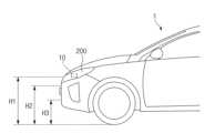
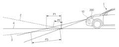
도 1을 참조하면, 본 발명에 따른 오브젝트 센싱장치(10)는, 외부 이물질의 침입으로 인한 오염 방지, 오브젝트의 신속하고 정확한 검출 등을 위하여 헤드램프, 안개등, 브레이크등, 사이드램프, 방향 지시등 등과 같은 다양한 차량용 램프조립체 내에 장착될 수 있다.Referring to FIG. 1, the
또한, 본 발명에 따른 오브젝트 센싱장치(10)는 차량의 전방 상단부에 배치됨으로써 오브젝트 센싱장치(10)의 지상고를 상대적으로 높일 수 있다. 이를 통해 차량이 언덕길 등과 같이 높낮이가 변화하는 지형을 주행할 때 지형 변화, 차량의 외부에 위치한 다른 차량, 사람 등과 같은 오브젝트를 신속하고 정확하게 인지할 수 있다.In addition, the
예컨대, 전방 헤드램프조립체(200)는 지상고 법규(headlight height regulations)에 따라 정해진 높이(H1) 이상의 위치에 배치되어야 한다. 이에 따라, 도 1과 같이 본 발명의 실시예에 따른 오브젝트 센싱장치(10)가 각 전방 헤드램프조립체(200) 내에 배치될 수 있고, 이를 통해 오브젝트 센싱장치(10)는 차량의 전방에서 오브젝트를 정확하게 인지할 수 있는 높이(H1)에 위치할 수 있다.For example, the
한편, 종래의 오브젝트 센싱장치는 차량의 전방 그릴의 중앙부 또는 하단에 배치됨에 따라 오브젝트 센싱장치의 높이(H2, H3)가 상대적으로 낮게 배치될 수 있다. 이에, 차량이 언덕길 등과 같이 높낮이가 변화하는 지형을 주행할 때 지형 변화, 차량의 외부에 위치한 다른 차량, 사람 등과 같은 오브젝트를 늦게 인지할 수 있고, 이에 주행보조, 자율주행을 실행할 때 그 대응이 매우 늦고 승차감이나 연비가 나빠질 수 있는 단점이 있다. 반면에, 본 발명의 실시예에 따른 오브젝트 센싱장치(10)는 전방 헤드램프조립체(200)에 배치됨으로써 종래기술에 비해 상대적으로 높은 위치(H1)에 배치될 수 있다. 이에 따라, 차량이 언덕길 등과 같이 높낮이가 변화하는 지형을 주행할 때 지형 변화, 차량의 외부에 위치한 다른 차량, 사람 등과 같은 오브젝트를 신속하고 정확하게 인지할 수 있고, 이에 주행보조, 자율주행을 실행할 때 그 대응이 매우 신속하고 승차감이나 연비가 개선될 수 있는 장점이 있다.Meanwhile, since the conventional object sensing device is placed in the center or bottom of the front grill of the vehicle, the heights (H2, H3) of the object sensing device may be placed relatively low. Accordingly, when a vehicle is driving on terrain with varying heights, such as a hill, it may be late to recognize changes in the terrain and objects such as other vehicles or people located outside the vehicle, and the corresponding response is required when executing driving assistance or autonomous driving. It is very slow and has the disadvantage of deteriorating ride quality and fuel efficiency. On the other hand, the
이하, 설명의 편의를 위하여 도면 상에서 본 발명의 오브젝트 센싱장치(10)가 전방 헤드램프조립체(200) 내에 장착된 구성을 도시하고 설명하지만, 본 발명은 이에 한정되지 않고, 오브젝트 센싱장치(10)가 안개등, 방향지시등, 브레이크등, 전조등 등과 같은 다양한 차량용 램프조립체 내에 장착될 수 있다.Hereinafter, for convenience of explanation, the configuration in which the
도 2를 참조하면, 전방 헤드램프조립체(200)는 램프하우징(210)과, 램프하우징(210) 내에 장착된 헤드램프(220)와, 램프하우징(210)의 전방측에 장착된 램프커버(230)를 포함할 수 있다. 일 예에 따르면, 헤드램프(220)는 수직축(Y1)의 둘레로 회전하도록 구성될 수 있고, 이를 통해 헤드램프(220)는 차량의 주행방향 또는 조향방향을 따라 빛을 조사하도록 수평축 둘레로 회전하는 DBL(Dynamic Bending Lighting) 기능을 실행할 수 있다.Referring to Figure 2, the
램프하우징(210)는 헤드램프(220)가 장착되는 제1장착공간(201) 및 오브젝트 센싱장치(10)가 장착되는 제2장착공간(202)를 포함할 수 있다. 제1장착공간(201) 및 제2장착공간(202)은 헤드램프(220) 및 오브젝트 센싱장치(10)가 서로 간의 열영향을 받지 않도록 충분히 이격될 수 있다. 제1장착공간(201)은 헤드램프(220)에 의한 배광영역이 될 수 있고, 제2장착공간(202)은 오브젝트 센싱장치(10)에 의한 센싱영역이 될 수 있다.The
일 예에 따르면, 램프커버(230)는 오브젝트 센싱장치(10)의 센싱 성능을 저하시킬 수 있는 금속성분이 포함하지 않도록 구성됨이 바람직하다. 또한, 램프커버(230)는 오브젝트 센싱장치(10)의 센싱 성능을 높이도록 빛을 투과할 수 있는 재질로 이루어짐이 바람직하다.According to one example, the
한편, 전방 헤드램프조립체(200)는 램프커버(230)의 표면에 부착된 이물질을 세정하기 위한 자기세정기구(미도시)를 가질 수 있고, 이에 전방 헤드램프조립체(200)의 세정기구(미도시)에 의해 램프커버(230)의 표면에 부착된 오염물질이 세정됨에 따라 오브젝트 센싱장치(10)의 센싱기능 저하를 방지할 수 있다.Meanwhile, the
도 16을 참조하면, 한 쌍의 전방 헤드램프조립체(200a, 200b)가 차량의 전방에 장착될 수 있고, 각 오브젝트 센싱장치(10)가 각 전방 헤드램프조립체(200a, 200b) 내에 배치될 수 있다. 이에 따라, 오브젝트 센싱장치(10)가 차량의 전방에서 오브젝트를 정확하게 인지할 수 있는 높이(H1)에 배치될 수 있고, 한 쌍의 오브젝트 센싱장치(10)가 한 쌍의 전방 헤드램프조립체(200) 내에 개별적으로 장착됨으로써 스테레오 타입의 오브젝트 센싱시스템을 구성할 수 있다. 각 전방 헤드램프조립체(200a, 200b)의 헤드램프(220)는 차량의 조향방향을 따라 회전하는 DBL(Dynamic Bending Light)기능을 구현하도록 구성될 수 있다.Referring to FIG. 16, a pair of front headlamp assemblies (200a, 200b) may be mounted at the front of the vehicle, and each
도 2를 참조하면, 본 발명의 실시예에 따른 오브젝트 센싱장치(10)는, 전방 헤드램프조립체(200)의 램프하우징(210) 내에서 서로 직교하는 2개의 축(X, Y) 둘레로 이동(피벗)하도록 구성된 오브젝트 센서(11)를 포함할 수 있다. 일 예에 따르면, 오브젝트 센서(11)는 수평축(X)의 둘레로 틸팅하고 수직축(Y)의 둘레로 회전하도록 구성될 수 있다.Referring to FIG. 2, the
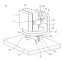
도 3 내지 도 7을 참조하면, 오브젝트 센싱장치(10)는 오브젝트 센서(11)를 수평축(X) 둘레로 틸팅시키도록 구성된 수직-틸팅기구(20)와, 오브젝트 센서(11)를 수직축(Y) 둘레로 회전시키도록 구성된 수평-로테이팅기구(30)를 포함할 수 있다.3 to 7, the
오브젝트 센서(11)는 라이다(lidar), 레이더(radar) 중에서 어느 하나이거나 라이다 및 레이더가 결합된 구조일 수 있다. 라이다는 레이저 시그널(laser signal)을 이용하는 센서이고, 레이더는 라디오 웨이브(radio wave)를 이용하는 센서이다.The
오브젝트 센서(11)는 센서홀더(12)에 장착될 수 있고, 센서홀더(12)는 지지바디(13)에 대해 수평축(X) 둘레로 틸팅하도록 구성될 수 있다. 지지바디(13)는 수평부(14) 및 수직부(15)를 가질 수 있다. 수직부(15)는 한 쌍의 지지돌기(16)를 가질 수 있으며, 센서홀더(12)는 한 쌍의 지지돌기(16)에 회전가능하게 장착되는 한 쌍의 제1피벗축(17)을 가질 수 있다.The
수직-틸팅기구(20)는 센서홀더(12)의 배면에 고정된 제1섹터기어(21)와, 제1섹터기어(21)에 치합되는 제1피니언(22)과, 제1피니언(22)을 회전시키는 제1엑츄에이터(23)를 포함할 수 있다.The vertical-tilting
제1섹터기어(21)는 일정 반경의 원호형상으로 이루어질 수 있다. 제1섹터기어(21)는 복수의 치형을 가질 수 있으며, 제1섹터기어(21)는 수직으로 배치될 수 있고, 제1섹터기어(21)는 제1피벗축(17) 둘레로 회전할 수 있다. 일 예에 따르면, 제1섹터기어(21)의 중심은 제1피벗축(17)의 중심과 일치할 수 있다.The
제1피니언(22)은 복수의 치형을 가질 수 있고, 제1피니언(22)의 치형들은 제1섹터기어(21)의 치형들과 치합될 수 있으며, 각 제1피니언(22)의 축선이 수평으로 연장됨으로써 한 쌍의 제1피니언(22)의 축선은 수평축선(X)이 될 수 있다.The
제1엑츄에이터(23)의 출력축은 제1피니언(22)의 중심에 결합될 수 있고, 이에 제1엑츄에이터(23)는 제1피니언(22)을 회전시키도록 구성될 수 있다. 제1엑츄에이터(23)는 지지바디(13)의 수직부(15)에 장착될 수 있다.The output shaft of the
수직-틸팅기구(20)는 제1엑츄에이터(23)에 의해 제1피니언(22)이 회전함에 따라 제1섹터기어(21)가 제1피벗축(17) 둘레로 회전할 수 있고, 이를 통해 오브젝트 센서(11)는 수평축(X) 둘레로 틸팅할 수 있다.The vertical-tilting
차량이 언덕길, 경사로 등을 주행할 때 수직-틸팅기구(20)에 의해 오브젝트 센서(11)가 수평축 둘레로 틸팅함으로써 오브젝트 센서(11)는 차량의 외부에 위치한 오브젝트를 정밀하게 센싱할 수 있다.When the vehicle drives on a hill, slope, etc., the
특히, 본 발명의 실시예에 따르면, 오브젝트 센싱장치(10)가 전방 헤드램프 조립체(200) 내에 배치됨으로써 오브젝트 센서(11)가 오브젝트를 인지할 수 있을 정도의 높이를 충분히 확보할 수 있고, 이를 통해 경사로 등과 같이 높낮이가 변화하는 지형을 주행할 때 오브젝트 센서(11)의 틸팅을 매우 유연하고 신속하게 실행할 수 있으므로 지형 변화, 선행 차량 등을 신속하고 정확하게 인지할 수 있다.In particular, according to an embodiment of the present invention, the
수평-로테이팅기구(30)는 지지바디(13)의 아래에 배치된 베이스(19)와, 베이스(19)에 장착된 제2섹터기어(31)와, 제2섹터기어(31)에 치합된 제2피니언(32)과, 제2피니언(32)을 회전시키는 제2엑츄에이터(33)를 포함할 수 있다.The horizontal-rotating
베이스(19)는 전방 헤드램프 조립체(200)의 램프하우징(210)에 장착될 수 있고, 지지바디(13)는 제2피벗축(18)을 통해 베이스(19)에 연결될 수 있다. 특히, 지지바디(13)의 수평부(14)가 제2피벗축(18)을 통해 베이스(19)에 회전가능하게 연결될 수 있고, 이를 통해 지지바디(13)는 제2피벗축(18) 둘레로 회전하도록 구성될 수 있다. 제2피벗축(18)의 축선이 수직으로 연장됨으로써 제2피벗축(18)의 축선은 수직축(Y)일 수 있다.The base 19 may be mounted on the
베이스(19)는 원호 형상의 슬롯(19a)을 가질 수 있고, 제2섹터기어(31)는 베이스(19)의 슬롯(19a)에 고정될 수 있다. 이에 제2섹터기어(31)는 일정 반경의 원호형상으로 이루어질 수 있다. 제2섹터기어(31)는 복수의 치형을 가질 수 있으며, 제2섹터기어(31)는 수평으로 배치될 수 있다. 지지바디(13)는 제2피벗축(18) 둘레로 회전할 수 있다. 일 예에 따르면, 제2섹터기어(31)의 중심은 제2피벗축(18)의 중심과 일치할 수 있다.The base 19 may have an arc-shaped
제2피니언(32)은 복수의 치형을 가질 수 있고, 제2피니언(32)의 치형들은 제2섹터기어(31)의 치형들과 치합될 수 있다. 제2피니언(32)은 수직으로 연장될 수 있다.The
제2엑츄에이터(33)의 출력축은 제2피니언(32)의 중심에 결합될 수 있고, 이에 제2엑츄에이터(33)는 제2피니언(32)을 회전시키도록 구성될 수 있다. 제2엑츄에이터(33)는 지지바디(13)의 수평부(14)에 장착될 수 있다.The output shaft of the
수평-로테이팅기구(30)는 제2엑츄에이터(33)에 의해 제2피니언(32)이 회전함에 따라 제2피니언(32)이 제2섹터기어(31)의 원호를 따라 이동할 수 있고, 이에 제2섹터기어9)는 제2피벗축(18) 둘레로 회전할 수 있고, 이를 통해 오브젝트 센서(11)는 수직축(Y)의 둘레로 회전할 수 있다.The horizontal-rotating
차량이 커브길을 주행하거나 유턴(U-turn)할 때 수평-로테이팅기구(30)에 의해 오브젝트 센서(11)가 수직축 둘레로 회전함으로써 차량의 외부에 위치한 오브젝트를 정확하게 센싱할 수 있다.When the vehicle drives on a curved road or makes a U-turn, the
본 발명의 오브젝트 센싱장치(10)는 지지바디(13)의 양 측면 및 후방면 등을 포위하는 히트프로텍터(40)를 더 포함할 수 있다. 히트프로텍터(40)는 헤드램프(220)의 열이 오브젝트 센서(11) 측으로 전달됨을 차단하도록 세라믹 소재 등과 같은 단열성 및 내열성을 가진 재질로 이루어질 수 있다.The
일 실시예에 따르면, 히트프로텍터(40)는 지지바디(13)의 후방면을 향해 면하는 제1벽(41)과, 지지바디(13)의 양 측면을 향해 면하는 한 쌍의 제2벽(42)을 포함할 수 있다. 지지바디(13)의 전방 및 상부를 개방될 수 있다.According to one embodiment, the
히트프로텍터(40)의 제1벽(41)의 하단 및 제2벽(42)들의 각 하단은 베이스(19)에 고정될 수 있고, 히트프로텍터(40)의 제1벽에는 쿨링팬(43)이 장착될 수 있다. 송풍가이드(44)가 쿨링팬(43)의 둘레에 배치될 수 있고, 송풍가이드(44)는 쿨링팬(43)에 의해 생성된 냉각풍을 오브젝트 센서(11)측으로 가이드하도록 구성될 수 있다.Each lower end of the
지지바디(13)는 쿨링팬(43)과 면하는 수직부(15)에 형성된 복수의 냉각홀(15a)을 가질 수 있고, 각 냉각홀(15a)은 슬롯 형상일 수 있다. 쿨링팬(43)에 의해 생성된 냉각풍이 냉각홀(15a)들을 통해 오브젝트 센서(11) 측으로 전달됨으로써 오브젝트 센서(11)의 과열이 방지될 수 있다.The
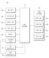
도 8은 본 발명의 실시예에 따른 오브젝트 센싱장치(10)가 연결된 차량 주행제어시스템(50)을 도시한다.Figure 8 shows a vehicle driving
차량 주행제어시스템(50)은 복수의 센서(52a, 52b, 52c, 52d, 52e)가 연결된 메인 컨트롤러(51)와, 메인 컨트롤러(51)와 협동하는 차량 컨트롤러(55)를 포함할 수 있다.The vehicle
복수의 센서(52a, 52b, 52c, 52d, 52e)는 헤드램프(220)의 DBL(Dynamic Bending Lighting)기능을 실행할 때 헤드램프(220)의 회전각 등을 센싱하는 DBL센서(52a), 차량의 현재 위치를 나타내고 목적지까지 길을 안내해주는 네비게이션(52b), 차량의 조향각를 센싱하는 조향각센서(52c), 차량의 속도를 센싱하는 차속센서(52d), 차량의 외부 환경을 촬영하는 카메라(52e) 등일 수 있다.A plurality of sensors (52a, 52b, 52c, 52d, 52e) include a DBL sensor (52a) that senses the rotation angle of the headlamp (220) when executing the DBL (Dynamic Bending Lighting) function of the headlamp (220), etc. A navigation system (52b) that displays the current location and guides the way to the destination, a steering angle sensor (52c) that senses the steering angle of the vehicle, a vehicle speed sensor (52d) that senses the vehicle's speed, and a camera (52e) that photographs the external environment of the vehicle. It may be, etc.
오브젝트 센싱장치(10)의 오브젝트 센서(11), 제1 및 제2 엑츄에이터()가 메인 컨트롤러(51)에 연결될 수 있다. 이에, 메인 컨트롤러(51)는 오브젝트 센서(11)로부터 오브젝트 센서(11)의 틸팅각, 회전각 등을 수신하고, 제1 및 제2 엑츄에이터(23, 33)에 제어명령을 전송하도록 구성될 수 있다.The
차량 컨트롤러(55)는 엔진을 제어하는 엔진 ECU(55a), 차량의 제동을 제어하는 제동 ECU(55b), 차량의 조향을 제어하는 조향 ECU(55c), 차량의 변속을 제어하는 변속 ECU(55d) 등을 포함할 수 있다.The
상술한 차량 주행제어시스템(50)은 주행보조 또는 자율주행 등을 실행하도록 구성될 수 있다.The vehicle
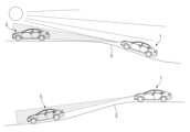
도 9a와 같이, 차량(1)이 오르막길(2)로 올라갈 때, 메인 컨트롤러(51)는 제1엑츄에이터(23) 측으로 상향 틸팅신호를 전송함으로써 도 9b와 같이 제1엑츄에이터(23)의 구동에 의해 제1피니언(22)이 반시계방향을 따라 회전하고, 제1피니언(22)과 치합된 제1섹터기어(21)는 제1피벗축(17) 둘레로 시계방향을 따라 회전할 수 있으며, 이를 통해 오브젝트 센서(11)는 상향으로 틸팅할 수 있다.As shown in FIG. 9A, when the
도 10a와 같이, 차량(1)이 내리막길(3)로 내려올때, 메인 컨트롤러(51)가 제1엑츄에이터(23) 측으로 오브젝트 센서(11)의 하향 틸팅신호를 전송함으로써 도 10b와 같이 제1엑츄에이터(23)의 구동에 의해 제1피니언(22)이 시계방향으로 회전하고, 제1피니언과 치합된 제1섹터기어(21)는 제1피벗축(17) 둘레로 반시계방향을 따라 회전하며, 이를 통해 오브젝트 센서(11)는 하향으로 틸팅할 수 있다.As shown in FIG. 10A, when the
도 11과 같이, 차량(1)이 오르막길(2)로 올라가고 내리막길(3)을 따라 내려갈때 카메라(52e)의 영상 촬영 및 오브젝트 센서(11)의 센싱 등에 의해 지형의 높낮이를 인식할 수 있고, 이를 통해 오브젝트 센서(11)가 상향 또는 하향으로 틸팅할 수 있다. 특히, 입력값의 신뢰도를 향상하기 위하여, 메인 컨트롤러(51)는 카메라(52e)로부터의 데이터 및 오브젝트 센서(11)로부터의 데이터를 비교 및 대조할 수 있다.As shown in FIG. 11, when the
도 12를 참조하면, 메인 컨트롤러(51)는 차량(1)이 오르막길(2)에 진입하기 전에 카메라(52e)에 의해 획득된 영상이미지의 면적(A1)과 차량이 오르막길(2)의 정점(8)에 진입하기 전에 카메라(52e)에 의해 획득된 영상이미지의 면적(A2)을 비교함으로써 지형의 높낮이(△H)를 인식 및 결정할 수 있다.Referring to FIG. 12, the
또한, 도 13을 참조하면, 메인 컨트롤러(51)는 오브젝트 센서(11)로부터 평탄한 도로(4)에 투사되는 에너지의 투사면적(P1)이 오브젝트 센서(11)로부터 오르막길(2)로 투사되는 에너지의 투사면적(P2) 보다 큰 것을 인식함으로써 차량(1)이 오르막길(2)로 진입하는 것을 판단할 수 있고, 이를 통해 메인 컨트롤러(51)는 오브젝트 센서(11)가 상향으로 틸팅하도록 제1엑츄에이터(23)를 제어할 수 있다. 메인 컨트롤러(51)는 오브젝트 센서(11)로부터 평탄한 도로(4)에 투사되는 에너지의 투사면적(P1)이 오브젝트 센서(11)로부터 내리막길(3)로 투사되는 에너지의 투사면적(P3) 보다 작은 것을 인식함으로써 차량(1)이 내리막길(3)로 진입하는 것을 판단할 수 있고, 이를 통해 메인 컨트롤러(51)는 오브젝트 센서(11)가 하향으로 틸팅하도록 제1엑츄에이터(23)를 제어할 수 있다.In addition, referring to FIG. 13, the
도 14를 참조하면, 차량(1)이 오르막길(2)을 따라 올라갈때 오브젝트 센서(11)가 상향으로 틸팅함으로써 선행 차량(5) 및 도로 조건 등을 능동적으로 인지할 수 있고, 차량(1)이 내리막길(3)을 따라 내려갈 때 오브젝트 센서(11)가 하향으로 틸팅함으로써 선행 차량(5) 및 도로 조건 등을 능동적으로 인지할 수 있다. 특히, 지면의 변화에 대응하여 오브젝트 센서(11)가 틸팅함에 따라 선행 차량(5)을 능동적으로 추적할 수 있으므로 햇빛을 회피할 수 있고, 이를 통해 햇빛에 의한 왜곡 및 간섭 등을 차단할 수 있으므로 오브젝트의 오인식을 방지할 수 있다. 즉, 차량(1)이 경사로를 따라 주행할 때 선행 차량(5) 및 지형 등을 정확하게 추적할 수 있으므로 그 인식율을 대폭 향상할 수 있다.Referring to FIG. 14, when the vehicle (1) goes uphill (2), the object sensor (11) tilts upward to actively recognize the preceding vehicle (5) and road conditions, and the vehicle (1) When going down this downhill road (3), the object sensor (11) tilts downward to actively recognize the preceding vehicle (5) and road conditions. In particular, as the
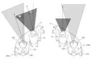
도 15를 참조하면, 차량(1)이 S자형 도로(6)을 주행할 때, 차량(Q)의 선회방향에 따라 오브젝트 센싱장치(10)의 오브젝트 센서(11)는 수평축 둘레로 회전할 수 있다. 특히, 한 쌍의 전방 헤드램프조립체(200a, 200b) 중에서 선회방향에 해당하는 선회측 전방 헤드램프조립체(200a)의 오브젝트 센서(11)만이 차량의 선회각도에 대응하도록 수평축 둘레로 회전하고, 차량(1)의 선회방향의 맞은측에 해당하는 전방 헤드램프조립체(200b)의 오브젝터 센서(11)는 원위치를 유지할 수 있다. 예컨대, 도 16과 같이, 차량(1)이 좌측으로 선회할 때 좌측에 위치한 전방 헤드램프조립체(200a)에 배치된 오브젝트 센싱장치(10)의 오브젝트 센서(11)만이 수직축 둘레를 따라 일정각도(θ)로 좌회전할 수 있고, 우측에 위치한 전방 헤드램프조립체(200b)에 배치된 오브젝트 센싱장치(10)의 오브젝트 센서(11)는 원위치를 유지한다. 그리고, 오브젝트 센싱장치(10)는 전방 헤드램프조립체(200a, 200b)의 헤드램프(220)가 DBL(Dynamic Bending Lighting) 기능과 연동할 수 있다. 이에 차량(1)이 좌측으로 선회할 때 좌측에 위치한 전방 헤드램프조립체(200a)의 헤드램프(220)만이 수직축 둘레를 따라 일정각도(θ')로 좌회전할 수 있고, 우측에 위치한 전방 헤드램프조립체(200b)의 헤드램프(220)는 원위치를 유지한다.Referring to FIG. 15, when the
도 17을 참조하면, 차량(1)이 작은 반경의 커브진 도로(7)를 따라 주행할 때, 차량(1)의 선회방향에 해당하는 선회측 전방 헤드램프조립체의 헤드램프 및 오브젝트 센서가 차량의 선회각도에 대응하도록 회전함으로써 커브진 도로(7)에서도 선행 차량(5) 및 주변 지행 등을 정확하고 신속하게 인지할 수 있다.Referring to FIG. 17, when the
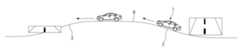
도 18을 참조하면, 차량(1)이 도로의 유턴구간 등에서 유턴할 때, 차량(1)의 선회방향에 해당하는 선회측 전방 헤드램프조립체의 헤드램프 및 오브젝트 센서가 차량의 선회각도에 대응하도록 회전하고, 차량(1)의 선회방향의 맞은편에 해당하는 반대측 전방 헤드램프조립체의 헤드램프 및 오브젝트 센서는 원위치를 유지할 수 있다. 이를 통해, 선행차량(1a), 주차차량(1b), 진입차량(1c) 등을 정확하고 신속하게 인지할 수 있다.Referring to FIG. 18, when the
도 15 내지 도 18에 도시된 바와 같이, 차량(1)이 S자형 도로(6), 커브진 도로(7), 유턴구간에서 선회할 때, 선회측에 해당하는 선회측 전방 헤드램프조립체의 오브젝트 센서 및 헤드램프만이 차량의 선회각도에 대응하도록 회전함으로써 오브젝트 센서(11)의 인지범위를 확장할 수 있고, 이를 통해 선행 차량, 주변 지형 등을 능동적으로 인지할 뿐만 아니라 그 선회 시의 속도를 안정적으로 제어할 수 있으므로 승차감의 변화, 사고 등을 미연에 방지할 수 있고, 연비 및 안전성을 확보할 수 있다.15 to 18, when the
도 19를 참조하면, 주행제어시스템(100)의 메인 컨트롤러(51)는 카메라(52e) 및 오브젝트 센서(11)로부터 전방도로의 환경 데이터를 수집한다(S1).Referring to FIG. 19, the
메인 컨트롤러(51)는 수집된 전방도로의 환경 데이터에 기초하여 지형 변화가 있는 지를 판단한다(S2).The
지형 변화가 있으면 메인 컨트롤러(51)는 지형 변화로 인해 선행 차량을 인지하는 것이 불가능한지를 판단한다(S3).If there is a change in terrain, the
지형 변화로 인해 선행 차량의 인지가 불가능하면 메인 컨트롤러(51)는 오브젝트 센싱장치(10)의 제1엑츄에이터(23) 측으로 상향 또는 하향 틸트 신호를 전달함(S4)으로써 오브젝트 센싱장치(10)의 오브젝트 센서(11)를 틸팅한다.If recognition of the preceding vehicle is impossible due to changes in terrain, the
그리고, 메인 컨트롤러(51)는 차속센서(52d)로부터 차량의 속도 데이터를 획득하고(S5), 틸트된 오브젝트 센서(11)에 의해 추출된 차선, 지형 변화 등에 대응하는 선행차량과의 거리를 계산한다(S6).Then, the
계산된 거리가 설정값 이하인지를 판단하고(S7), 계산된 거리가 설정값 이하이면 메인 컨트롤러(51)는 차속을 늦추거나 긴급제동 또는 VDC(Vehicle Dynamic Control)을 실행한다(S8).It is determined whether the calculated distance is less than the set value (S7), and if the calculated distance is less than the set value, the
도 20을 참조하면, 주행제어시스템(100)의 메인 컨트롤러(51)는 네비게이션(52b)으로부터 도로 데이터를 수집하고(S11), 조향각 센서(52c)로부터 조향 데이터를 획득하며(S12), 카메라(52e) 및 오브젝트 센서(11)로부터 전방도로의 환경 데이터를 수집한다(S13).Referring to FIG. 20, the
메인 컨트롤러(51)는 수집된 전방도로의 환경 데이터에 기초하여 차량의 선회 여부를 판단한다(S14).The
메인 컨트롤러(51)는 차량의 선회로 인해 선행 차량을 인지하는 것이 불가능한지를 판단한다(S15).The
차량의 선회로 인해 선행 차량의 인지가 불가능하면 메인 컨트롤러(51)는 오브젝트 센싱장치(10)의 제2엑츄에이터(33) 측으로 좌측 또는 우측 회전 신호를 전달함(S16)으로써 오브젝트 센싱장치(10)의 오브젝트 센서(11)를 수직축 둘레로 회전시킨다.If it is impossible to recognize the preceding vehicle due to the vehicle turning, the
그리고, 메인 컨트롤러(51)는 차속센서(52d)로부터 차량의 속도 데이터를 획득하고(S17), 회전된 오브젝트 센서(11)에 의해 추출된 차선, 지형 변화 등에 대응하는 선행차량과의 거리를 계산한다(S18).Then, the
계산된 거리가 설정값 이하인지를 판단하고(S19), 계산된 거리가 설정값 이하이면 메인 컨트롤러(51)는 차속을 늦추거나 긴급제동 또는 VDC(Vehicle Dynamic Control)을 실행한다(S20).It is determined whether the calculated distance is less than the set value (S19), and if the calculated distance is less than the set value, the
도 21을 참조하면, 주행제어시스템(100)의 메인 컨트롤러(51)는 DBL센서(52a)으로부터 각 전방 헤드램프조립체(200a, 200b)의 헤드램프(220)의 회전 정보를 수집하고(S21), 카메라(52e) 및 오브젝트 센서(11)로부터 전방도로의 환경 데이터를 수집한다(S22).Referring to FIG. 21, the
메인 컨트롤러(51)는 수집된 전방도로의 환경 데이터에 기초하여 차량의 선회 여부를 판단한다(S23).The
메인 컨트롤러(51)는 차량의 선회로 인해 선행 차량을 인지하는 것이 불가능한지를 판단한다(S24).The
차량의 선회로 인해 선행 차량의 인지가 불가능하면 메인 컨트롤러(51)는 오브젝트 센싱장치(10)의 제2엑츄에이터(33) 측으로 좌측 또는 우측 회전 신호를 전달함(S25)으로써 오브젝트 센싱장치(10)의 오브젝트 센서(11)를 수직축 둘레로 회전시킨다.If recognition of the preceding vehicle is impossible due to the vehicle turning, the
그리고, 메인 컨트롤러(51)는 차속센서(52d)로부터 차량의 속도 데이터를 획득하고(S26), 회전된 오브젝트 센서(11)에 의해 추출된 차선, 지형 변화 등에 대응하는 선행차량과의 거리를 계산한다(S27).Then, the
계산된 거리가 설정값 이하인지를 판단하고(S28), 계산된 거리가 설정값 이하이면 메인 컨트롤러(51)는 차속을 늦추거나 긴급제동 또는 VDC(Vehicle Dynamic Control)을 실행한다(S29).It is determined whether the calculated distance is less than the set value (S28), and if the calculated distance is less than the set value, the
이상과 같은 본 발명의 실시예에 따른 오브젝트 센싱장치(10)는 램프 하우징(210) 내에 위치함으로써 높은 지상고를 통해 운전환경에 대한 인지성을 확보하고, 레이아웃 및 센서 작동환경의 요구사항을 다각적으로 만족시킬 수 있다. 또한, 오브젝트 센싱장치(10)는 수직 틸팅기능에 의해 지형변화(지형의 높낮이 변화 등)를 용이하게 인지함으로써 사각지대 해소, 선행 차량을 용이하게 인식함으로써 급작스러운 선행 차량 발견이나 오인식 등으로 인한 급제동 및 제어 불능상태로 인한 사고 가능성을 최소화할 수 있다. 그리고, 오브젝트 센싱장치(10)는 수평로테이팅기능에 의해 연속된 선회로의 선행 차량의 추적 및 및 인지력 개선과 자율 주행에 의한 유턴과 인터체인지 진입 및 탈출, 주차장 진입 및 탈출 등 다양한 주행환경에서의 주행능력을 확장할 수 있다.The
또한, 본 발명의 오브젝트 센싱장치(10)의 수직 틸팅기능 및 수평로테이팅기능은 자율주행에 필수적인 Lidar(Light Detection and Ranging)센서, 자동긴급제동시스템 (Autonomous Emergency Braking system) 뿐만 아니라, 초음파를 이용한 주차보조센서(Front/Rear Parking Assistant Sensor)와 같이 종래의 다양한 센서에도 적용이 가능하며, 차량의 좌/우에 장착된 스테레오 타입의 오브젝트 센싱시스템으로 구현될 수 있으므로 차량의 중앙에 장착된 센서대비 인지범위가 확대되는 효과가 있다.In addition, the vertical tilting function and horizontal rotating function of the
그리고, 본 발명의 오브젝트 센싱장치(10)는 정상작동 조건이나 카메라의 화각을 만족시키기 용이하며 현재까지 작동조건 만족을 위한 디자인 수정량을 최소화할 수 있다. 이는 다양한 센서가 복합적으로 탑재 요구되는 상황에도 용이하다.In addition, the
이상의 설명은 본 발명의 기술 사상을 예시적으로 설명한 것에 불과한 것으로서, 본 발명이 속하는 기술 분야에서 통상의 지식을 가진 자라면 본 발명의 본질적인 특성에서 벗어나지 않는 범위에서 다양한 수정 및 변형이 가능할 것이다.The above description is merely an illustrative explanation of the technical idea of the present invention, and various modifications and variations will be possible to those skilled in the art without departing from the essential characteristics of the present invention.
따라서, 본 발명에 개시된 실시예들은 본 발명의 기술 사상을 한정하기 위한 것이 아니라 설명하기 위한 것이고, 이러한 실시예에 의하여 본 발명의 기술 사상의 범위가 한정되는 것은 아니다. 본 발명의 보호 범위는 아래의 청구범위에 의하여 해석되어야 하며, 그와 동등한 범위 내에 있는 모든 기술 사상은 본 발명의 권리범위에 포함되는 것으로 해석되어야 할 것이다.Accordingly, the embodiments disclosed in the present invention are not intended to limit the technical idea of the present invention, but are for illustrative purposes, and the scope of the technical idea of the present invention is not limited by these embodiments. The scope of protection of the present invention should be interpreted in accordance with the claims below, and all technical ideas within the equivalent scope should be construed as being included in the scope of rights of the present invention.
10: 오브젝트 센싱장치11: 오브젝트 센서
12: 센서홀더13: 지지바디
14: 수평부15: 수직부
16: 지지돌기17: 제1피벗축
18: 제2피벗축19: 베이스
20: 수직-틸팅기구21: 제1섹터기어
22: 제1피니언23: 제1엑츄에이터
30: 수평-로테이팅기구31: 제2섹터기어
32: 제2피니언33: 제2엑츄에이터
40: 히트 프로텍터41: 제1벽
42: 제2벽43: 쿨링벽
44: 송풍가이드50: 차량 주행제어시스템
51: 메인컨트롤러55: 차량 컨트롤러
200: 전방 헤드램프조립체210: 램프하우징
220: 헤드램프230: 헤드커버10: object sensing device 11: object sensor
12: Sensor holder 13: Support body
14: horizontal part 15: vertical part
16: Support projection 17: First pivot axis
18: second pivot axis 19: base
20: vertical-tilting mechanism 21: first sector gear
22: first pinion 23: first actuator
30: horizontal-rotating mechanism 31: second sector gear
32: second pinion 33: second actuator
40: Heat Protector 41: First Wall
42: second wall 43: cooling wall
44: Blowing guide 50: Vehicle driving control system
51: main controller 55: vehicle controller
200: Front headlamp assembly 210: Lamp housing
220: headlamp 230: head cover
Claims (14)
Translated fromKorean상기 오브젝트 센서를 수평축 둘레로 틸팅시키도록 구성된 수직-틸팅기구; 및
상기 오브젝트 센서를 수직축 둘레로 회전시키도록 구성된 수평-로테이팅기구;를 포함하고,
상기 오브젝트 센서는 센서홀더에 장착되고, 상기 센서홀더는 지지바디에 대해 수평축 둘레로 틸팅하도록 장착되며,
상기 수직-틸팅기구는 상기 센서홀더의 배면에 고정된 제1섹터기어와, 상기 제1섹터기어에 치합되는 제1피니언과, 상기 제1피니언을 회전시키는 제1엑츄에이터를 포함하는 오브젝트 센싱장치.Object sensor mounted on the front of the vehicle;
a vertical-tilting mechanism configured to tilt the object sensor about a horizontal axis; and
A horizontal-rotating mechanism configured to rotate the object sensor about a vertical axis,
The object sensor is mounted on a sensor holder, and the sensor holder is mounted to tilt around a horizontal axis with respect to the support body,
The vertical-tilting mechanism includes a first sector gear fixed to the back of the sensor holder, a first pinion engaged with the first sector gear, and a first actuator for rotating the first pinion.
상기 오브젝트 센서는 차량의 램프조립체 내에 장착되는 오브젝트 센싱장치.In claim 1,
The object sensor is an object sensing device mounted within a lamp assembly of a vehicle.
상기 지지바디는 한 쌍의 지지돌기를 가지고, 상기 센서홀더는 상기 한 쌍의 지지돌기에 회전가능하게 장착되는 한 쌍의 제1피벗축을 가지며, 상기 한 쌍의 제1피벗축의 축선은 수평축인 오브젝트 센싱장치.
In claim 1,
The support body has a pair of support protrusions, the sensor holder has a pair of first pivot axes rotatably mounted on the pair of support protrusions, and the axis of the pair of first pivot axes is a horizontal axis. Sensing device.
상기 제1엑츄에이터는 상기 지지바디에 장착되는 오브젝트 센싱장치.In claim 1,
The first actuator is an object sensing device mounted on the support body.
상기 수평-로테이팅기구는 지지바디의 아래에 위치하는 베이스와, 상기 베이스에 장착된 제2섹터기어와, 상기 제2섹터기어에 치합되는 제2피니언과, 상기 제2피니언을 회전시키는 제2엑츄에이터를 포함하는 오브젝트 센싱장치.In claim 1,
The horizontal-rotating mechanism includes a base located below the support body, a second sector gear mounted on the base, a second pinion engaged with the second sector gear, and a second pinion that rotates the second pinion. Object sensing device including an actuator.
상기 지지바디는 상기 베이스에 대해 제2피벗축을 통해 회전가능하게 연결되며, 상기 제2피벗축의 축선은 수직축인 오브젝트 센싱장치.In claim 7,
The support body is rotatably connected to the base through a second pivot axis, and the axis of the second pivot axis is a vertical axis.
상기 베이스는 원호 형상의 슬롯을 가지고, 상기 제2섹터기어는 상기 베이스의 슬롯에 고정되는 오브젝트 센싱장치.In claim 8,
The base has an arc-shaped slot, and the second sector gear is fixed to the slot of the base.
상기 지지바디의 양 측면 및 후방면을 포위하는 히트프로텍터를 더 포함하는 오브젝트 센싱장치.In claim 7,
An object sensing device further comprising a heat protector surrounding both sides and a rear surface of the support body.
상기 히트프로텍터는 상기 지지바디의 후방면을 향해 면하는 제1벽과, 상기 지지바디의 양 측면을 향해 면하는 한 쌍의 제2벽을 가지는 오브젝트 센싱장치.In claim 10,
The heat protector is an object sensing device having a first wall facing the rear surface of the support body and a pair of second walls facing both sides of the support body.
상기 히트프로텍터는 상기 제1벽에 장착된 쿨링팬을 더 포함하는 오브젝트 센싱장치.In claim 11,
The heat protector is an object sensing device further comprising a cooling fan mounted on the first wall.
상기 히트프로텍터는 상기 쿨링팬의 둘레에 배치되는 송풍가이드를 더 포함하는 오브젝트 센싱장치.In claim 12,
The heat protector is an object sensing device further comprising a blowing guide disposed around the cooling fan.
상기 지지바디는 상기 쿨링팬과 면하는 부분에 복수의 냉각홀을 가지는 오브젝트 센싱장치.In claim 13,
The support body is an object sensing device having a plurality of cooling holes in a portion facing the cooling fan.
Priority Applications (4)
| Application Number | Priority Date | Filing Date | Title |
|---|---|---|---|
| KR1020180148688AKR102610744B1 (en) | 2018-11-27 | 2018-11-27 | Object sensing apparatus |
| DE102019118090.2ADE102019118090A1 (en) | 2018-11-27 | 2019-07-04 | Object detection device |
| CN201910605571.0ACN111239767B (en) | 2018-11-27 | 2019-07-05 | Object sensing apparatus |
| US16/511,939US11417112B2 (en) | 2018-11-27 | 2019-07-15 | Object sensing apparatus |
Applications Claiming Priority (1)
| Application Number | Priority Date | Filing Date | Title |
|---|---|---|---|
| KR1020180148688AKR102610744B1 (en) | 2018-11-27 | 2018-11-27 | Object sensing apparatus |
Publications (2)
| Publication Number | Publication Date |
|---|---|
| KR20200062820A KR20200062820A (en) | 2020-06-04 |
| KR102610744B1true KR102610744B1 (en) | 2023-12-07 |
Family
ID=70546122
Family Applications (1)
| Application Number | Title | Priority Date | Filing Date |
|---|---|---|---|
| KR1020180148688AActiveKR102610744B1 (en) | 2018-11-27 | 2018-11-27 | Object sensing apparatus |
Country Status (4)
| Country | Link |
|---|---|
| US (1) | US11417112B2 (en) |
| KR (1) | KR102610744B1 (en) |
| CN (1) | CN111239767B (en) |
| DE (1) | DE102019118090A1 (en) |
Families Citing this family (8)
| Publication number | Priority date | Publication date | Assignee | Title |
|---|---|---|---|---|
| KR102663206B1 (en)* | 2019-04-23 | 2024-05-03 | 현대자동차주식회사 | Lidar ntegrated lamp device for vehicle |
| KR102634026B1 (en)* | 2019-10-25 | 2024-02-08 | 현대모비스 주식회사 | Sensor cluster device and vehicle comprising the same |
| JP2022014975A (en)* | 2020-07-08 | 2022-01-21 | トヨタ自動車株式会社 | Vehicle peripheral monitoring device |
| AT524633A1 (en)* | 2020-12-22 | 2022-07-15 | Avl List Gmbh | METHOD OF CONTROLLING A LIGHT CONE |
| JPWO2023017796A1 (en)* | 2021-08-10 | 2023-02-16 | ||
| JP2023061263A (en)* | 2021-10-19 | 2023-05-01 | スタンレー電気株式会社 | lamp device |
| KR102751215B1 (en)* | 2022-06-24 | 2025-01-10 | 디와이오토 주식회사 | Lamp system for vehicle with integrated cleaning nozzle and autonomous driving sensor |
| JP2025008058A (en)* | 2023-07-04 | 2025-01-20 | 株式会社ソミックマネージメントホールディングス | Autonomous Vehicle Device |
Citations (1)
| Publication number | Priority date | Publication date | Assignee | Title |
|---|---|---|---|---|
| JP2008162391A (en)* | 2006-12-27 | 2008-07-17 | Koito Mfg Co Ltd | Vehicular lamp |
Family Cites Families (32)
| Publication number | Priority date | Publication date | Assignee | Title |
|---|---|---|---|---|
| US3707721A (en)* | 1954-10-05 | 1972-12-26 | Sperry Rand Corp | Servo control system |
| US4142695A (en)* | 1971-10-27 | 1979-03-06 | Raytheon Company | Vehicle guidance system |
| NL8400008A (en)* | 1984-01-03 | 1985-08-01 | Hollandse Signaalapparaten Bv | ARRANGEMENT FOR A ROUND SEARCH. |
| JPH06286521A (en)* | 1993-02-10 | 1994-10-11 | Ford Motor Co | Method and device for automatic shifting of car head light to low beam |
| JP3259475B2 (en)* | 1993-10-27 | 2002-02-25 | ミノルタ株式会社 | Distance measuring device |
| KR200171900Y1 (en)* | 1996-12-31 | 2000-04-01 | 정몽규 | Irradiation angle adjusting device of headlamp according to steering angle |
| KR19990007582A (en)* | 1998-10-09 | 1999-01-25 | 이인애 | Traffic Surveillance Vehicle |
| EP1130416A3 (en)* | 2000-03-02 | 2002-01-30 | Denso Corporation | Forward condition detecting apparatus for vehicles |
| JP2001325816A (en)* | 2000-05-15 | 2001-11-22 | Koito Mfg Co Ltd | Headlight for vehicle |
| JP3560540B2 (en)* | 2000-10-03 | 2004-09-02 | 株式会社デンソー | Automatic adjustment of the headlight optical axis direction for vehicles |
| KR100681756B1 (en) | 2004-12-14 | 2007-02-15 | 성균관대학교산학협력단 | Variable exchange scrambling method |
| KR20080007780A (en)* | 2006-07-18 | 2008-01-23 | 현대자동차주식회사 | Radar Steering with Adaptive Cruise Control System |
| US7965384B2 (en)* | 2007-09-27 | 2011-06-21 | Omron Scientific Technologies, Inc. | Clutter rejection in active object detection systems |
| JP2009120068A (en)* | 2007-11-15 | 2009-06-04 | Tokai Rika Co Ltd | Acceleration sensor |
| IL192601A (en)* | 2008-07-03 | 2014-07-31 | Elta Systems Ltd | Sensing/emitting apparatus, system and method |
| IT1391142B1 (en)* | 2008-07-11 | 2011-11-18 | Univ Firenze | LIGHTING DEVICE FOR TRACKING THE ROUTE |
| CN101788668B (en)* | 2010-01-31 | 2012-05-30 | 中国海洋大学 | Quasi double doppler laser radar device and measuring method thereof |
| KR20110120128A (en) | 2010-04-28 | 2011-11-03 | 서울대학교산학협력단 | Directional Control System and Method for Vehicle Radar and Vision System |
| KR20130136107A (en) | 2012-06-04 | 2013-12-12 | 현대모비스 주식회사 | An automobile |
| DE102012107544B3 (en)* | 2012-08-17 | 2013-05-23 | Faro Technologies, Inc. | Optical scanning device i.e. laser scanner, for evaluating environment, has planetary gears driven by motor over vertical motor shaft and rotating measuring head relative to foot, where motor shaft is arranged coaxial to vertical axle |
| JP6019959B2 (en)* | 2012-09-06 | 2016-11-02 | 富士通株式会社 | Object detection device, object detection program, and vehicle |
| US10233819B2 (en)* | 2013-05-03 | 2019-03-19 | Deere & Company | Dual-pivot hinge for fan |
| AT514402B1 (en)* | 2013-05-16 | 2015-09-15 | Zizala Lichtsysteme Gmbh | vehicle headlights |
| KR102173994B1 (en) | 2014-03-18 | 2020-11-04 | 주식회사 만도 | Tuning method and control device of vehicle radar |
| KR102312410B1 (en) | 2014-12-03 | 2021-10-13 | 현대모비스 주식회사 | Apparatus Controlling Location of Ultrasonic Sensor for Vehicle and Method Thereof |
| DE102015213694A1 (en)* | 2015-07-21 | 2017-01-26 | Robert Bosch Gmbh | Sensor system for detecting protruding or exposed objects in the vicinity of a vehicle |
| CN205618400U (en)* | 2016-04-14 | 2016-10-05 | 台州通达机电有限公司 | Energy -saving blower motor for car |
| ITUA20163925A1 (en)* | 2016-05-30 | 2017-11-30 | Magneti Marelli Spa | Electrical machine with tangential architecture with improved air cooling |
| DE102016011327A1 (en)* | 2016-09-21 | 2018-03-22 | Wabco Gmbh | LiDAR sensor with compact design |
| FR3058227B1 (en)* | 2016-10-27 | 2018-11-02 | Thales | FLEXW MULTIFUNCAL RADAR, IN PARTICULAR FOR AUTOMOBILE |
| CN107064953A (en)* | 2017-03-21 | 2017-08-18 | 华勤通讯技术有限公司 | A kind of localization method and device based on laser radar |
| CN107702685A (en)* | 2017-11-13 | 2018-02-16 | 深圳中天云隼科技有限公司 | Precision angle head |
- 2018
- 2018-11-27KRKR1020180148688Apatent/KR102610744B1/enactiveActive
- 2019
- 2019-07-04DEDE102019118090.2Apatent/DE102019118090A1/enactivePending
- 2019-07-05CNCN201910605571.0Apatent/CN111239767B/enactiveActive
- 2019-07-15USUS16/511,939patent/US11417112B2/enactiveActive
Patent Citations (1)
| Publication number | Priority date | Publication date | Assignee | Title |
|---|---|---|---|---|
| JP2008162391A (en)* | 2006-12-27 | 2008-07-17 | Koito Mfg Co Ltd | Vehicular lamp |
Also Published As
| Publication number | Publication date |
|---|---|
| US11417112B2 (en) | 2022-08-16 |
| DE102019118090A1 (en) | 2020-05-28 |
| KR20200062820A (en) | 2020-06-04 |
| CN111239767B (en) | 2024-06-07 |
| CN111239767A (en) | 2020-06-05 |
| US20200167577A1 (en) | 2020-05-28 |
Similar Documents
| Publication | Publication Date | Title |
|---|---|---|
| KR102610744B1 (en) | Object sensing apparatus | |
| EP3428027B1 (en) | Driving system for vehicle | |
| CN102897083B (en) | The light distribution control of head light | |
| EP2281719B1 (en) | Light distribution control system for automotive headlamp | |
| CN103097196B (en) | Device and method for adjusting the lighting of a vehicle in unclear curves | |
| US8738235B2 (en) | Detection method for a motor vehicle | |
| JP5075355B2 (en) | Obstacle detection device having an imaging system for automobiles | |
| JP5375880B2 (en) | Vehicle headlamp device | |
| WO2021153622A1 (en) | Vehicle control device, vehicle control method, and vehicle control system | |
| JP2012228978A (en) | Vehicular headlight apparatus | |
| JP2009040227A (en) | Vehicular headlight control device | |
| JP2008105518A (en) | Camera built-in lamp | |
| CN116176404B (en) | Automatic control method and control system for high beam and low beam lamps and vehicle with system | |
| JP5623145B2 (en) | VEHICLE LIGHT SYSTEM, ITS CONTROL DEVICE, AND VEHICLE LIGHT | |
| CN110356312A (en) | Anti-glare control method, system and the vehicle of vehicle | |
| JP4586342B2 (en) | Headlamp control system | |
| JP2018024351A (en) | Automatic operation system | |
| JP2009184640A (en) | Headlight device of vehicle | |
| JP2006096158A (en) | Light distribution control device for vehicle headlight | |
| US6926430B2 (en) | Anti-dazzle safety device for a motor vehicle | |
| KR102394952B1 (en) | Lamp for vehicle and controlling method applied to the same | |
| JP3833822B2 (en) | Vehicle headlight control device | |
| CN115675447A (en) | Parking information prompt method, system, vehicle, electronic device and storage medium | |
| CN103448607A (en) | An automobile | |
| JP2009029367A (en) | Head lamp control device for vehicle |
Legal Events
| Date | Code | Title | Description |
|---|---|---|---|
| PA0109 | Patent application | St.27 status event code:A-0-1-A10-A12-nap-PA0109 | |
| R18-X000 | Changes to party contact information recorded | St.27 status event code:A-3-3-R10-R18-oth-X000 | |
| R18-X000 | Changes to party contact information recorded | St.27 status event code:A-3-3-R10-R18-oth-X000 | |
| P22-X000 | Classification modified | St.27 status event code:A-2-2-P10-P22-nap-X000 | |
| PG1501 | Laying open of application | St.27 status event code:A-1-1-Q10-Q12-nap-PG1501 | |
| PN2301 | Change of applicant | St.27 status event code:A-3-3-R10-R13-asn-PN2301 St.27 status event code:A-3-3-R10-R11-asn-PN2301 | |
| A201 | Request for examination | ||
| PA0201 | Request for examination | St.27 status event code:A-1-2-D10-D11-exm-PA0201 | |
| P22-X000 | Classification modified | St.27 status event code:A-2-2-P10-P22-nap-X000 | |
| D13-X000 | Search requested | St.27 status event code:A-1-2-D10-D13-srh-X000 | |
| D14-X000 | Search report completed | St.27 status event code:A-1-2-D10-D14-srh-X000 | |
| E902 | Notification of reason for refusal | ||
| PE0902 | Notice of grounds for rejection | St.27 status event code:A-1-2-D10-D21-exm-PE0902 | |
| E13-X000 | Pre-grant limitation requested | St.27 status event code:A-2-3-E10-E13-lim-X000 | |
| P11-X000 | Amendment of application requested | St.27 status event code:A-2-2-P10-P11-nap-X000 | |
| P13-X000 | Application amended | St.27 status event code:A-2-2-P10-P13-nap-X000 | |
| E701 | Decision to grant or registration of patent right | ||
| PE0701 | Decision of registration | St.27 status event code:A-1-2-D10-D22-exm-PE0701 | |
| PR0701 | Registration of establishment | St.27 status event code:A-2-4-F10-F11-exm-PR0701 | |
| PR1002 | Payment of registration fee | St.27 status event code:A-2-2-U10-U11-oth-PR1002 Fee payment year number:1 | |
| PG1601 | Publication of registration | St.27 status event code:A-4-4-Q10-Q13-nap-PG1601 |