KR102609740B1 - Fixing unit for thigh, fixing unit for calf and power assisting robot having the same - Google Patents
Fixing unit for thigh, fixing unit for calf and power assisting robot having the sameDownload PDFInfo
- Publication number
- KR102609740B1 KR102609740B1KR1020180021295AKR20180021295AKR102609740B1KR 102609740 B1KR102609740 B1KR 102609740B1KR 1020180021295 AKR1020180021295 AKR 1020180021295AKR 20180021295 AKR20180021295 AKR 20180021295AKR 102609740 B1KR102609740 B1KR 102609740B1
- Authority
- KR
- South Korea
- Prior art keywords
- thigh
- calf
- sub
- frame
- main
- Prior art date
- Legal status (The legal status is an assumption and is not a legal conclusion. Google has not performed a legal analysis and makes no representation as to the accuracy of the status listed.)
- Active
Links
- 210000000689upper legAnatomy0.000titleclaimsabstractdescription389
- 244000309466calfSpecies0.000titleclaimsabstractdescription278
- 210000003205muscleAnatomy0.000claimsabstractdescription44
- 210000002414legAnatomy0.000claimsabstractdescription37
- 210000001624hipAnatomy0.000claimsabstractdescription11
- 210000004197pelvisAnatomy0.000claimsabstractdescription6
- 230000008878couplingEffects0.000claimsdescription142
- 238000010168coupling processMethods0.000claimsdescription142
- 238000005859coupling reactionMethods0.000claimsdescription142
- 238000004804windingMethods0.000claimsdescription82
- 238000003780insertionMethods0.000claimsdescription14
- 230000037431insertionEffects0.000claimsdescription14
- 239000006260foamSubstances0.000claimsdescription7
- 230000003387muscularEffects0.000claims3
- 238000000605extractionMethods0.000claims2
- 238000010586diagramMethods0.000description17
- 238000000034methodMethods0.000description4
- 238000011109contaminationMethods0.000description3
- 230000006866deteriorationEffects0.000description3
- 230000000694effectsEffects0.000description2
- 208000034819Mobility LimitationDiseases0.000description1
- 230000032683agingEffects0.000description1
- 238000005452bendingMethods0.000description1
- 238000004140cleaningMethods0.000description1
- 239000013013elastic materialSubstances0.000description1
- 238000005516engineering processMethods0.000description1
- 210000004394hip jointAnatomy0.000description1
- 210000000629knee jointAnatomy0.000description1
- 238000012986modificationMethods0.000description1
- 230000004048modificationEffects0.000description1
- 239000011359shock absorbing materialSubstances0.000description1
- 238000010618wire wrapMethods0.000description1
Images


Classifications
- A—HUMAN NECESSITIES
- A61—MEDICAL OR VETERINARY SCIENCE; HYGIENE
- A61H—PHYSICAL THERAPY APPARATUS, e.g. DEVICES FOR LOCATING OR STIMULATING REFLEX POINTS IN THE BODY; ARTIFICIAL RESPIRATION; MASSAGE; BATHING DEVICES FOR SPECIAL THERAPEUTIC OR HYGIENIC PURPOSES OR SPECIFIC PARTS OF THE BODY
- A61H3/00—Appliances for aiding patients or disabled persons to walk about
- A—HUMAN NECESSITIES
- A61—MEDICAL OR VETERINARY SCIENCE; HYGIENE
- A61H—PHYSICAL THERAPY APPARATUS, e.g. DEVICES FOR LOCATING OR STIMULATING REFLEX POINTS IN THE BODY; ARTIFICIAL RESPIRATION; MASSAGE; BATHING DEVICES FOR SPECIAL THERAPEUTIC OR HYGIENIC PURPOSES OR SPECIFIC PARTS OF THE BODY
- A61H1/00—Apparatus for passive exercising; Vibrating apparatus; Chiropractic devices, e.g. body impacting devices, external devices for briefly extending or aligning unbroken bones
- A61H1/02—Stretching or bending or torsioning apparatus for exercising
- A61H1/0237—Stretching or bending or torsioning apparatus for exercising for the lower limbs
- A61H1/0255—Both knee and hip of a patient, e.g. in supine or sitting position, the feet being moved together in a plane substantially parallel to the body-symmetrical plane
- A61H1/0262—Walking movement; Appliances for aiding disabled persons to walk
- A—HUMAN NECESSITIES
- A61—MEDICAL OR VETERINARY SCIENCE; HYGIENE
- A61H—PHYSICAL THERAPY APPARATUS, e.g. DEVICES FOR LOCATING OR STIMULATING REFLEX POINTS IN THE BODY; ARTIFICIAL RESPIRATION; MASSAGE; BATHING DEVICES FOR SPECIAL THERAPEUTIC OR HYGIENIC PURPOSES OR SPECIFIC PARTS OF THE BODY
- A61H3/00—Appliances for aiding patients or disabled persons to walk about
- A61H2003/007—Appliances for aiding patients or disabled persons to walk about secured to the patient, e.g. with belts
- A—HUMAN NECESSITIES
- A61—MEDICAL OR VETERINARY SCIENCE; HYGIENE
- A61H—PHYSICAL THERAPY APPARATUS, e.g. DEVICES FOR LOCATING OR STIMULATING REFLEX POINTS IN THE BODY; ARTIFICIAL RESPIRATION; MASSAGE; BATHING DEVICES FOR SPECIAL THERAPEUTIC OR HYGIENIC PURPOSES OR SPECIFIC PARTS OF THE BODY
- A61H2201/00—Characteristics of apparatus not provided for in the preceding codes
- A61H2201/16—Physical interface with patient
- A61H2201/1602—Physical interface with patient kind of interface, e.g. head rest, knee support or lumbar support
- A61H2201/1628—Pelvis
- A61H2201/163—Pelvis holding means therefor
- A—HUMAN NECESSITIES
- A61—MEDICAL OR VETERINARY SCIENCE; HYGIENE
- A61H—PHYSICAL THERAPY APPARATUS, e.g. DEVICES FOR LOCATING OR STIMULATING REFLEX POINTS IN THE BODY; ARTIFICIAL RESPIRATION; MASSAGE; BATHING DEVICES FOR SPECIAL THERAPEUTIC OR HYGIENIC PURPOSES OR SPECIFIC PARTS OF THE BODY
- A61H2201/00—Characteristics of apparatus not provided for in the preceding codes
- A61H2201/16—Physical interface with patient
- A61H2201/1602—Physical interface with patient kind of interface, e.g. head rest, knee support or lumbar support
- A61H2201/164—Feet or leg, e.g. pedal
- A61H2201/1642—Holding means therefor
- A—HUMAN NECESSITIES
- A61—MEDICAL OR VETERINARY SCIENCE; HYGIENE
- A61H—PHYSICAL THERAPY APPARATUS, e.g. DEVICES FOR LOCATING OR STIMULATING REFLEX POINTS IN THE BODY; ARTIFICIAL RESPIRATION; MASSAGE; BATHING DEVICES FOR SPECIAL THERAPEUTIC OR HYGIENIC PURPOSES OR SPECIFIC PARTS OF THE BODY
- A61H2201/00—Characteristics of apparatus not provided for in the preceding codes
- A61H2201/16—Physical interface with patient
- A61H2201/1602—Physical interface with patient kind of interface, e.g. head rest, knee support or lumbar support
- A61H2201/165—Wearable interfaces
Landscapes
- Health & Medical Sciences (AREA)
- Epidemiology (AREA)
- Pain & Pain Management (AREA)
- Physical Education & Sports Medicine (AREA)
- Rehabilitation Therapy (AREA)
- Life Sciences & Earth Sciences (AREA)
- Animal Behavior & Ethology (AREA)
- General Health & Medical Sciences (AREA)
- Public Health (AREA)
- Veterinary Medicine (AREA)
- Orthopedic Medicine & Surgery (AREA)
- Rehabilitation Tools (AREA)
Abstract
Translated fromKoreanDescription
Translated fromKorean본 발명은 허벅지 고정유닛, 종아리 고정유닛 및 이를 포함하는 근력 보조 로봇에 관한 것이다.The present invention relates to a thigh fixation unit, a calf fixation unit, and a muscle strength assistance robot including the same.
최근 로봇 관련 기술의 폭넓은 적용에 따라, 장애나 노화 등으로 근력이 저하되어 보행이 어려운 사람들을 위한 보행보조장치가 널리 사용되고 있다.Recently, with the widespread application of robot-related technology, walking assistance devices for people who have difficulty walking due to reduced muscle strength due to disability or aging are being widely used.
일반적으로 보행보조장치는 사용자가 탑승한 후 전동식으로 구동되는 탑승식 장치와, 사용자가 착용하고 보행 등의 재활 훈련을 하는 착용식 장치가 있다.In general, walking assistance devices include a ride-on device that is electrically driven after the user gets on board, and a wearable device that the user wears and performs rehabilitation training such as walking.
착용식(wearable type) 장치는 다관절의 골격 구조를 갖는 일종의 로봇으로, 사용자가 착용했을 때 사용자의 근력을 보조하는 역할을 한다. 착용식 장치는 모터 등의 구동장치로부터 발생되는 구동력을 사용자에게 제공함으로써 근력을 보조한다.A wearable type device is a type of robot with a multi-joint skeletal structure that assists the user's muscle strength when worn. Wearable devices assist muscle strength by providing driving force generated from a driving device such as a motor to the user.
이중에서 종래기술에 따른 착용식(wearable type) 장치는 일본공개특허 제2006-087533호에 "보행 보조 장치의 허리 부분 지지구"로 개시되어 있다.Among them, a wearable type device according to the prior art is disclosed in Japanese Patent Publication No. 2006-087533 as “lumbar support device for walking assistance device.”
보다 구체적으로, 도 1 및 도 2에 도시한 바와 같이, 종래의 보행 보조 장치는 대퇴부 지지부의 상하 방향 중간 위치에 한 쌍의 대퇴부 결합 클립(9)가 소정 범위를 상하로 슬라이드 가능하게 결합된다. 그리고 대퇴부 결합 클립(9)은 탄성의 C자형 부재로 이루어진다.More specifically, as shown in FIGS. 1 and 2, in the conventional walking assistance device, a pair of thigh coupling clips 9 are coupled to a mid-position in the vertical direction of the thigh support portion so as to be able to slide up and down a predetermined range. And the thigh coupling clip 9 is made of an elastic C-shaped member.
또한, 종아리부 지지부의 상하 방향 중간 위치에는 한 쌍의 종아리부 결합 클립(10)이 소정 범위를 상하로 슬라이드 가능하게 결합된다. 그리고 종아리부 결합 클립(10) 역시 탄성의 C자형 부재로 이루어진다.In addition, a pair of calf coupling clips 10 are coupled to the mid-position of the calf support part in the vertical direction so as to be able to slide up and down over a predetermined range. And the calf coupling clip 10 is also made of an elastic C-shaped member.
상기한 바와 같이 이루어 짐에 따라, 종래기술에 따른 종래의 보행 보조 장치의 종아리 및 허벅지 고정구조는 사용자가 탄성의 C자형 부재로 이루어진 대퇴구 결합 클립(9)와 종아리부 결합 클립(10)에 각각 종아리와 허벅지를 고정할 수 있을 수 있다.As described above, the calf and thigh fixing structure of the conventional walking assistance device according to the prior art allows the user to attach the thigh coupling clip 9 and the calf coupling clip 10 made of an elastic C-shaped member. It may be possible to secure the calf and thigh respectively.
그리나, 대퇴구 결합 클립(9)와 종아리부 결합 클립은 단순히 일체형으로 이루어진 C자형 탄성부재로 이루어짐에 따라, 사용자의 다양한 신체구조에 맞도록 변형시켜 사용할 수 없는 문제점을 지니고 있다.However, since the thigh coupling clip 9 and the calf coupling clip are simply made of an integrated C-shaped elastic member, they have a problem in that they cannot be modified and used to suit the user's various body structures.
또한, 종래기술에 따른 보행 보조 장치의 종아리 및 허벅지 고정구조는 사용자가 착용한 후 고정할 수 있는 고정구조를 포함하고 있지 않아, 착용 후 의도치 않게 벗겨질 수 있어 안전상 위험한 문제점을 지지고 있다.In addition, the calf and thigh fixing structure of the walking assistance device according to the prior art does not include a fixing structure that can be fixed after the user wears it, so it can be unintentionally removed after wearing, which poses a safety hazard.
또한, 종래기술에 따른 보행 보조 장치의 종아리 및 허벅지 고정구조는 사용자가 착용 후 고정의 조임 정도를 조절할 수 없어, 사용자의 신체구조 및 사용 목적에 맞도록 조정하여 사용할 수 없는 문제점을 지니고 있다.In addition, the calf and thigh fixation structure of the walking assistance device according to the prior art has a problem in that the user cannot adjust the tightness of the fixation after wearing it, so it cannot be adjusted to suit the user's body structure and purpose of use.
또한, 종래기술에 따른 보행 보조 장치의 종아리 및 허벅지 고정구조는 신체에 접촉되는 부위가 소프트하게 이루어지지 않음에 따라 사용자가 착용시 불편하고, 불쾌감을 느낄 수 있는 문제점을 지니고 있다.In addition, the calf and thigh fixation structure of the walking assistance device according to the prior art has a problem in that the user may feel uncomfortable and uncomfortable when wearing it because the area in contact with the body is not soft.
또한, 종래기술에 따른 보행 보조 장치의 종아리 및 허벅지 고정구조는 벨트에 의해 추가로 고정할 수 있으나 미사용시 벨트가 외부로 노출되어 있어, 벨트 오염, 벨트 파손 및 미관저하의 문제점을 지니고 있다.In addition, the calf and thigh fixing structure of the walking assistance device according to the prior art can be additionally fixed with a belt, but the belt is exposed to the outside when not in use, which has problems of belt contamination, belt damage, and deterioration of aesthetics.
본 발명은 사용자가 근력 보조 로봇을 착용할 경우, 허벅지 고정유닛 및 종아리 고정유닛에 각각 자신의 허벅지와 종아리가 삽입된 후 자연스럽게 피팅됨에 따라 사용자의 신체구조와 무관하게 사용할 수 있는 근력 보조 로봇의 허벅지 고정유닛 및 종아리 고정유닛을 제공하기 위한 것이다.The present invention provides a thigh of a strength assistance robot that can be used regardless of the user's body structure as the user's thighs and calves are inserted into the thigh fixation unit and the calf fixation unit, respectively, and then naturally fit, when the user wears the strength assistance robot. It is intended to provide a fixation unit and a calf fixation unit.
본 발명은 사용자가 근력 보조 로봇을 착용하고, 벨트 결합부를 이용하여 허벅지와 종아리에 대한 착용상태를 고정함에 따라 안전하게 사용할 수 있는 근력 보조 로봇의 허벅지 고정유닛 및 종아리 고정유닛을 제공하기 위한 것이다.The present invention is to provide a thigh fixing unit and a calf fixing unit of a muscle strength assistance robot that can be safely used by a user wearing the muscle strength assistance robot and fixing the wearing condition on the thigh and calf using a belt joint.
본 발명은 사용자가 허벅지와 종아리에 각각 허벅지 고정유닛 및 종아리 고정유닛을 고정시킨 후, 사용자의 신체 사이즈 및 사용 목적에 맞도록 조임정도를 조절할 수 있는 있는 근력 보조 로봇의 허벅지 고정유닛 및 종아리 고정유닛을 제공하기 위한 것이다.The present invention provides a thigh fixing unit and calf fixing unit of a muscle strength assistance robot that allows the user to fix the thigh fixing unit and calf fixing unit to the thigh and calf, respectively, and then adjust the degree of tightening to suit the user's body size and purpose of use. It is intended to provide.
본 발명은 사용자가 허벅지와 종아리에 각각 허벅지 고정유닛 및 종아리 고정유닛의 결합상태를 해제시킬 경우, 원터치 방식으로 간편하게 해제시킬 수 있는 근력 보조 로봇의 허벅지 고정유닛 및 종아리 고정유닛을 제공하기 위한 것이다.The present invention is intended to provide a thigh fixing unit and a calf fixing unit of a muscle strength assistance robot that can be easily released with a one-touch method when the user releases the coupling state of the thigh fixing unit and the calf fixing unit to the thigh and calf, respectively.
본 발명은 사용자의 신체에 접촉되는 부위를 소프트한 영역으로 형성시킴에 따라 사용자가 편안하게 착용하고 움직일 수 있는 근력 보조 로봇의 허벅지 고정유닛 및 종아리 고정유닛을 제공하기 위한 것이다.The present invention is intended to provide a thigh fixing unit and a calf fixing unit for a muscle strength assistance robot that can be comfortably worn and moved by the user by forming a soft area at the area in contact with the user's body.
본 발명은 사용자의 허벅지 및 종아리를 고정하는 벨트가 미사용시 외부로 노출되지 않도록 수납가능한 근력 보조 로봇의 허벅지 고정유닛 및 종아리 고정유닛을 제공하기 위한 것이다.The present invention is to provide a thigh fixing unit and a calf fixing unit for a muscle strength assistance robot that can be stored so that the belt that fixes the user's thighs and calves is not exposed to the outside when not in use.
본 발명의 목적들은 이상에서 언급한 목적으로 제한되지 않으며, 언급되지 않은 본 발명의 다른 목적 및 장점들은 하기의 설명에 의해서 이해될 수 있고, 본 발명의 실시예에 의해 보다 분명하게 이해될 것이다. 또한, 본 발명의 목적 및 장점들은 특허 청구 범위에 나타낸 수단 및 그 조합에 의해 실현될 수 있음을 쉽게 알 수 있을 것이다.The objects of the present invention are not limited to the objects mentioned above, and other objects and advantages of the present invention that are not mentioned can be understood by the following description and will be more clearly understood by the examples of the present invention. Additionally, it will be readily apparent that the objects and advantages of the present invention can be realized by the means and combinations thereof indicated in the patent claims.
본 발명에 따른 근력 보조 로봇의 허벅지 고정유닛 및 종아리 고정유닛은 메인 허벅지 지지부의 양측에 탄성적으로 지지되도록 힌지결합된 제1 서브 허벅지 지지부와 제2 서브 허벅지 지지부를 포함하여 신체구조와 무관하게 허벅지 고정유닛 및 종아리 고정유닛이 신체에 피팅되도록 사용할 수 있다.The thigh fixation unit and the calf fixation unit of the muscle strength assistance robot according to the present invention include a first sub-thigh support portion and a second sub-thigh support portion that are hinged to be elastically supported on both sides of the main thigh support portion, so that the thigh is maintained regardless of the body structure. The fixation unit and calf fixation unit can be used to fit the body.
본 발명에 따른 근력 보조 로봇의 허벅지 고정유닛 및 종아리 고정유닛은 벨트 결합부를 포함하여 허벅지 및 종아리를 벨트로 고정시켜 안전하게 사용할 수 있다.The thigh fixation unit and the calf fixation unit of the muscle strength assistance robot according to the present invention include a belt joint and can be safely used by fixing the thigh and calf with a belt.
본 발명에 따른 근력 보조 로봇의 허벅지 고정유닛 및 종아리 고정유닛은 와이어 권취 구조체를 포함하고, 벨트 결합부를 이용하여 허벅지 및 종아리를 각각 벨트로 고정시킨 상태에서 와이어 권취 구조체를 이용하여 벨트의 길이를 신체 사이즈에 맞도록 조정할 수 있다.The thigh fixing unit and the calf fixing unit of the muscle strength assistance robot according to the present invention include a wire winding structure, and while the thigh and calf are respectively fixed with a belt using a belt joint, the length of the belt is adjusted to the body using the wire winding structure. You can adjust it to fit your size.
본 발명에 따른 근력 보조 로봇의 허벅지 고정유닛 및 종아리 고정유닛은 벨트 결합부의 결합상태를 고정하거나 해제시키는 버튼식 다이얼을 포함하여 원터치 방식으로 허벅지 및 종아리에 고정된 벨트의 결합을 해제시킬 수 있다.The thigh fixation unit and the calf fixation unit of the muscle strength assistance robot according to the present invention include a button-type dial that fixes or releases the coupling state of the belt coupling portion, and can release the coupling of the belt fixed to the thigh and calf with a one-touch method.
본 발명에 따른 근력 보조 로봇의 허벅지 고정유닛 및 종아리 고정유닛은 쿠션부를 포함하여 사용자에게 부드러운 질감 및 쿠션감을 제공할 수 있다.The thigh fixing unit and the calf fixing unit of the muscle strength assistance robot according to the present invention can provide a soft texture and cushioning feeling to the user by including a cushion part.
본 발명에 따른 근력 보조 로봇의 허벅지 고정유닛 및 종아리 고정유닛은 벨트에 연결된 와이어 권취부와, 와이어 권취부에 와이어 권취력을 제공하는 판 스프링을 포함하여 버튼식 다이얼을 통해 벨트 결합부의 결합상태를 해제시킬 경우, 판 스프링의 복원력에 의해 와이어가 권취되고, 와이어의 권취에 연동되어 벨트가 외부로 노출되지 않도록 수납시킬 수 있다.The thigh fixing unit and the calf fixing unit of the muscle strength assistance robot according to the present invention include a wire winding unit connected to a belt and a leaf spring that provides wire winding force to the wire winding unit, and the coupling state of the belt coupling unit is monitored through a button-type dial. When released, the wire is wound by the restoring force of the leaf spring, and in conjunction with the winding of the wire, the belt can be stored so that it is not exposed to the outside.
본 발명에 따른 근력 보조 로봇의 허벅지 고정유닛 및 종아리 고정유닛은 사용자가 근력 보조 로봇을 착용하기 위해 허벅지 고정유닛 및 종아리 고정유닛에 각각 허벅지와 종아리가 삽입할 경우 서브 바디부가 벌어졌다가 다시 좁혀짐에 따라 허벅지와 종아리에 맞도록 피팅된다.The thigh fixing unit and calf fixing unit of the strength assistance robot according to the present invention causes the sub-body portion to open and then narrow again when the user inserts the thigh and calf into the thigh fixing unit and the calf fixing unit, respectively, to wear the strength assistance robot. It is fitted to fit the thighs and calves.
이에 따라 사용자의 신체구조와 무관하게 남녀노소 누구나 사용할 수 있고, 착용감을 향상시킬 수 있게 된다.As a result, anyone regardless of the user's body structure can use it, regardless of age, and the wearing comfort can be improved.
본 발명에 따른 근력 보조 로봇의 허벅지 고정유닛 및 종아리 고정유닛은 벨트 결합부를 이용하여 허벅지와 종아리를 벨트가 각각 감싸도록 고정함에 따라, 의도하지 않게 근력 보조 로봇이 허벅지 또는 종아리로부터 이탈되는 상태를 미연에 방지할 수 있어 보다 안전하게 사용할 수 있게 된다.The thigh fixation unit and calf fixation unit of the strength assistance robot according to the present invention uses a belt joint to fix the thigh and calf so that the belts respectively surround them, thereby preventing the strength assistance robot from unintentionally being separated from the thigh or calf. This makes it possible to use it more safely.
본 발명에 따른 근력 보조 로봇의 허벅지 고정유닛 및 종아리 고정유닛은 사용자가 허벅지와 종아리에 각각 허벅지 고정유닛 및 종아리 고정유닛을 고정시킨 후, 사용자의 신체 사이즈 및 사용 목적에 맞도록 조임정도를 조절할 수 있는 있다.The thigh fixing unit and calf fixing unit of the muscle strength assistance robot according to the present invention allows the user to fix the thigh fixing unit and calf fixing unit to the thigh and calf, respectively, and then adjust the degree of tightening to suit the user's body size and purpose of use. There is.
이에 따라, 사용자는 앉아서 허벅지 고정유닛과 종아리 고정유닛을 1차로 고정하고, 일어선 상태에서 조임정도를 조절하여 2차로 고정함에 따라 헐렁거림 없이 허벅지 고정유닛과 종아리 고정유닛을 고정시켜 사용할 수 있게 된다.Accordingly, the user can sit down and fix the thigh fixing unit and the calf fixing unit first, and adjust the degree of tightness while standing up to fix it secondarily, thereby fixing the thigh fixing unit and the calf fixing unit without looseness. .
본 발명에 따른 근력 보조 로봇의 허벅지 고정유닛 및 종아리 고정유닛은 사용자가 허벅지와 종아리에 각각 허벅지 고정유닛 및 종아리 고정유닛의 결합상태를 해제시킬 경우, 원터치 방식으로 간편하게 해제시킬 수 있다.The thigh fixation unit and calf fixation unit of the muscle strength assistance robot according to the present invention can be easily released with a one-touch method when the user releases the coupling state of the thigh fixation unit and calf fixation unit to the thigh and calf, respectively.
이에 따라 사용자는 근력 보조 로봇을 착용한 상태에서 간편하고 빠르게 벋을 수 있게 된다.As a result, users will be able to easily and quickly get off their feet while wearing the strength assistance robot.
본 발명에 따른 근력 보조 로봇의 허벅지 고정유닛 및 종아리 고정유닛은 사용자의 신체에 접촉되는 부위를 소프트한 영역으로 형성시킴에 따라 사용자가 편안하게 착용하고 움직일 수 있다.The thigh fixation unit and the calf fixation unit of the muscle strength assistance robot according to the present invention form a soft area at the area in contact with the user's body, allowing the user to wear and move comfortably.
이에 따라 사용자는 장시간 근력 보조 로봇을 사용할 경우에도 허벅지 고정유닛 및 종아리 고정유닛의 접촉 영역에 무리가 가지 않고 사용할 수 있게 된다.Accordingly, even when using the strength assistance robot for a long period of time, the user can use it without causing strain to the contact areas of the thigh fixation unit and calf fixation unit.
본 발명에 따른 근력 보조 로봇의 허벅지 고정유닛 및 종아리 고정유닛은 벨트 결합부를 해제시킬 경우, 사용자의 허벅지 및 종아리를 고정하는 벨트가 본체 내부로 수납됨에 따라 미사용시 외부로 노출되지 않게 된다.When the belt coupling portion of the thigh fixing unit and the calf fixing unit of the strength assistance robot according to the present invention is released, the belt fixing the user's thighs and calves is stored inside the main body and is not exposed to the outside when not in use.
이에 따라 허벅지 고정유닛 및 종아리 고정유닛의 미사용시에는 벨트가 외부로 노출되어 있어, 벨트 오염, 벨트 파손 및 미관저하의 문제점을 미연에 방지할 수 있게 된다.Accordingly, when the thigh fixing unit and the calf fixing unit are not in use, the belt is exposed to the outside, making it possible to prevent belt contamination, belt damage, and deterioration of aesthetics.
상술한 효과와 더불어 본 발명의 구체적인 효과는 이하 발명을 실시하기 위한 구체적인 사항을 설명하면서 함께 기술한다.In addition to the above-described effects, specific effects of the present invention are described below while explaining specific details for carrying out the invention.
도 1은 종래기술에 따른 보행 보조 장치를 개략적으로 도시한 구성도이다.
도 2는 종래기술에 따른 보행 보조 장치의 개략적인 사용상태도이다.
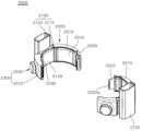
도 3은 본 발명의 일실시예에 따른 근력 보조 로봇에 장착된 허벅지 및 종아리 고정유닛을 개략적으로 도시한 구성도이다.
도 4은 도 3에 도시한 근력 보조 로봇의 개략적인 개략적인 측면도이다.
도 5는 도 3에 도시한 근력 보조 로봇에 있어서 허벅지 고정유닛을 개략적으로 도시한 사시도이다.
도 6은 도 5에 도시한 허벅지 고정유닛에 있어서, 허벅지 벨트 결합부가 해제된 상태를 개략적으로 도시한 구성도이다.
도 7은 도 6에 도시한 허벅지 고정유닛의 개략적인 평면도이다.
도 8는 도 6에 도시한 허벅지 고정유닛에 있어서, 메인 허벅지 지지부, 제1 서브 허벅지 지지부 및 제2 서브 허벅지 지지부의 프레임에 대한 개략적인 분해사시도이다.
도 9는 도 8에 도시한 내측 메인 허벅지 프레임, 내측 제1 서브 허벅지 프레임 및 내측 제2 서브 허벅지 프레임이 결합된 상태를 개략적으로 도시한 구성도이다.
도 10은 도 7에 도시한 허벅지 고정유닛의 개략적인 사용상태도이다.
도 11는 도 5에 도시한 허벅지 고정유닛의 개략적인 단면도이다.
도 12는 도 5에 도시한 허벅지 고정유닛의 개략적인 분해사시도이다.
도 13은 도 11에 도시한 허벅지 고정유닛의 개략적인 제1 사용상태도이다.
도 14는 도 11에 도시한 허벅지 고정유닛의 개략적인 제2 사용상태도이다.
도 15는 도 3에 도시한 근력 보조 로봇에 있어서, 종아리 고정유닛을 개략적으로 도시한 사시도이다.
도 16은 도 15에 도시한 종아리 고정유닛에 있어서, 종아리 벨트 결합부가 해제된 상태를 개략적으로 도시한 구성도이다.
도 17은 도 16에 도시한 종아리 고정유닛의 개략적인 평면도이다.
도 18은 도 16에 도시한 종아리 고정유닛에 있어서, 메인 종아리 지지부, 제1 서브 종아리 바디부 및 제2 서브 종아리 바디부의 프레임에 대한 개략적인 분해사시도이다.
도 19는 도 15에 도시한 종아리 고정유닛의 개략적인 단면도이다.
도 20은 도 15에 도시한 종아리 고정유닛의 개략적인 분해사시도이다.1 is a diagram schematically showing the configuration of a walking assistance device according to the prior art.
Figure 2 is a schematic diagram of a state of use of a walking assistance device according to the prior art.
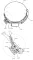
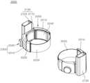
Figure 3 is a configuration diagram schematically showing a thigh and calf fixation unit mounted on a muscle strength assistance robot according to an embodiment of the present invention.
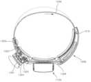
Figure 4 is a schematic side view of the muscle strength assistance robot shown in Figure 3.
Figure 5 is a perspective view schematically showing a thigh fixing unit in the muscle assistance robot shown in Figure 3.
Figure 6 is a configuration diagram schematically showing the thigh fixing unit shown in Figure 5 in a state in which the thigh belt coupling portion is released.
Figure 7 is a schematic plan view of the thigh fixing unit shown in Figure 6.
Figure 8 is a schematic exploded perspective view of the frames of the main thigh support part, the first sub thigh support part, and the second sub thigh support part in the thigh fixing unit shown in Figure 6.
FIG. 9 is a configuration diagram schematically showing a state in which the inner main thigh frame, the inner first sub-thigh frame, and the inner second sub-thigh frame shown in FIG. 8 are combined.
Figure 10 is a schematic diagram of the use state of the thigh fixing unit shown in Figure 7.
Figure 11 is a schematic cross-sectional view of the thigh fixing unit shown in Figure 5.
Figure 12 is a schematic exploded perspective view of the thigh fixing unit shown in Figure 5.
Figure 13 is a schematic first use state diagram of the thigh fixing unit shown in Figure 11.
Figure 14 is a schematic second use state diagram of the thigh fixing unit shown in Figure 11.
Figure 15 is a perspective view schematically showing a calf fixing unit in the muscle strength assistance robot shown in Figure 3.
Figure 16 is a configuration diagram schematically showing the calf fixing unit shown in Figure 15 in a state in which the calf belt coupling portion is released.
Figure 17 is a schematic plan view of the calf fixing unit shown in Figure 16.
Figure 18 is a schematic exploded perspective view of the frame of the main calf support part, the first sub calf body part, and the second sub calf body part in the calf fixing unit shown in Figure 16.
Figure 19 is a schematic cross-sectional view of the calf fixing unit shown in Figure 15.
Figure 20 is a schematic exploded perspective view of the calf fixing unit shown in Figure 15.
본 명세서 및 특허청구범위에 사용된 용어나 단어는 통상적이거나 사전적인 의미로 한정해서 해석되어서는 아니 되며, 발명자는 그 자신의 발명을 가장 최선의 방법으로 설명하기 위해 용어의 개념을 적절하게 정의할 수 있다는 원칙에 입각하여, 본 발명의 기술적 사상에 부합되는 의미와 개념으로 해석되어야만 한다. 또한, 본 명세서에 기재된 실시예와 도면에 도시된 구성은 본 발명의 가장 바람직한 하나의 실시예에 불과할 뿐이고, 본 발명의 기술적 사상을 모두 대변하는 것은 아니므로, 본 출원시점에 있어서 이들을 대체할 수 있는 다양한 균등물과 변형예들이 있을 수 있음을 이해하여야 한다.Terms or words used in this specification and claims should not be construed as limited to their ordinary or dictionary meanings, and the inventor may appropriately define the concept of terms in order to explain his or her invention in the best way. Based on the principle that it can be done, it must be interpreted with meaning and concept consistent with the technical idea of the present invention. In addition, the embodiments described in this specification and the configurations shown in the drawings are only one of the most preferred embodiments of the present invention and do not represent the entire technical idea of the present invention, so they cannot be replaced at the time of filing the present application. It should be understood that there may be various equivalents and variations.
도 3은 본 발명의 일실시예에 따른 근력 보조 로봇에 장착된 허벅지 및 종아리 고정유닛을 개략적으로 도시한 구성도이고, 도 4은 도 3에 도시한 근력 보조 로봇의 개략적인 개략적인 측면도이다.Figure 3 is a configuration diagram schematically showing a thigh and calf fixation unit mounted on a muscle strength assistance robot according to an embodiment of the present invention, and Figure 4 is a schematic side view of the muscle strength assistance robot shown in Figure 3.
도시한 바와 같이, 근력 보조 로봇(1)는 사용자가 하체에 착용하고 보행 등의 재활 훈련을 할 때 사용자의 하체 근력을 보조한다.As shown, the
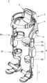
보다 구체적으로, 근력 보조 로봇(1)은 메인 컨트롤 유닛(2), 서브 컨트롤 유닛(3), 메인 프레임 유닛(4), 서브 프레임 유닛(5), 레그 유닛(6) 및 신발 고정 유닛(7)을 포함한다.More specifically, the strength assistance robot (1) includes a main control unit (2), a sub-control unit (3), a main frame unit (4), a sub-frame unit (5), a leg unit (6), and a shoe fixing unit (7). ) includes.
또한, 메인 컨트롤 유닛(2)은 근력 보조 로봇(1)의 기능을 제거하기 위한 것으로 메인 프레임 유닛(4) 상에 구비된다. 또한, 메인 컨트롤 유닛(2)은 사용자의 허리 에 대향되도록 위치한다.In addition, the main control unit (2) is provided on the main frame unit (4) to eliminate the function of the muscle assistance robot (1). Additionally, the
그리고 메인 컨트롤 유닛(2)은 사용자의 신체 사이즈에 따라 메인 프레임 유닛(4)의 폭을 조절할 수 있다. 또한, 메인 컨트롤 유닛(2)은 근력 보조 로봇의 동작을 위해 전원을 제공하는 배터리 팩을 구비할 수 있다. 메인 컨트롤 유닛(2)에는 서브 프레임 유닛(5)이 결합된다.And the main control unit (2) can adjust the width of the main frame unit (4) according to the user's body size. Additionally, the
서브 프레임 유닛(5)은 사용자의 허리를 지지하고, 허리에 결합되는 부분이다. 서브 프레임 유닛(5)은 원터치 방식으로 길이 조절이 가능한 벨트에 의해 사용자의 허리에 장착된다. 사용자의 허리와 접촉되는 부분은 충격 흡수가 가능한 소재가 부착되어 사용자의 착용감을 향상시킬 수 있다.The
메인 프레임 유닛(4)은 메인 컨트롤 유닛(2)을 지지하며, 사용자의 골반과 허리측에 대향되도록 위치되며, 사용자의 골반 일측에서 타측까지를 감싸는 형태를 갖는다.The
또한, 메인 프레임 유닛(4)은 대략 'U'자 형상으로, 절곡된 부분에 메인 컨트롤 유닛(2)이 장착된다. 메인 프레임 유닛(4)의 절곡된 부분은 사용자의 허리 쪽에 위치한다.In addition, the
그리고 메인 프레임 유닛(4)의 양단부는 사용자의 다리를 향해 하향 배치된다. 따라서 메인 프레임 유닛(4)은 양측에 경사진 부분이 존재하게 되는데, 이 부분에 서브 컨트롤 유닛(3)이 각각 구비된다.And both ends of the
또한, 서브 컨트롤 유닛(3)은 사용자의 근력을 보조하는 보조력의 강약을 조절하는 부분이다. 그리고 서브 컨트롤 유닛(3)은 회전 다이얼 방식으로 보조력을 조절할 수 있다.Additionally, the
또한, 서브 컨트롤 유닛(3)에는 보조력의 정도를 램프로 표시하는 인디케이터가 구비될 수 있다. 서브 컨트롤 유닛(3) 내부에 보조력을 제공하는 구동수단이 구비될 수 있다. 서브 컨트롤 유닛(3)의 하측에 레그 유닛(6)이 결합된다.Additionally, the
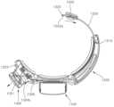
다음으로, 레그 유닛(6)은 사용자의 양쪽 다리에 각각 착용되어야 하므로 한 쌍으로 구비된다.Next, the
또한, 레그 유닛(6)은 어퍼 레그 프레임(6a), 레그 구동부(6b), 벨트(6c), 로어 레그 프레임(6d), 허벅지 고정유닛(6e) 및 종아리 고정유닛(6f)를 포함한다.In addition, the
그리고 어퍼 레그 프레임(6a)은 사용자의 허벅지 쪽에 장착되고, 레그 구동부(6b)은 어퍼 레그 프레임(6a) 상에 구비되어 보조력을 제공한다.The
그리고 허벅지 고정유닛(6e)은 어퍼 레그 프레임(6a)에 장착된다.And the
또한, 로어 레그 프레임(6d)은 사용자의 종아리 쪽에 장착되고, 벨트(6c)는 허벅지 고정유닛(6e)과 종아리 고정유닛(6f)에 결합되어 사용자의 다리를 감싸도록 구성된다.In addition, the
그리고 종아리 고정유닛(6f)은 로어 레그 프레임(6d)에 장착된다.And the calf fixing unit (6f) is mounted on the lower leg frame (6d).
그리고 허벅지 고정유닛(6e)은 사용자의 다리 중에서 허벅지에 결합되고, 종아리 고정유닛(6f)은 사용자의 다리 중에서 종아리에 결합된다.And the
보다 구체적으로, 어퍼 레그 프레임(6a) 및 로어 레그 프레임(6d), 레그 구동부(6b)는 사용자의 보행 시 관절 부위의 원활한 굽힘 운동을 위해 사용자의 다리 측면에 배치된다. 또한, 허벅지 고정유닛(6e)과 종아리 고정유닛(6f)에는 원터치 다이얼 방식으로 길이가 조절되는 벨트(6c)가 각각 구비된다.More specifically, the
또한, 어퍼 레그 프레임(6a) 및 로어 레그 프레임(6d)은 벨트(6c)에 의해 사용자의 다리에 탈착 가능하게 결합된다. 어퍼 레그 프레임(6a) 및 로어 레그 프레임(6d)은 레그 구동부(6b)를 기준으로 사용자의 무릎 관절 운동 방향에 대응하는 방향으로 회전된다.Additionally, the
그리고 어퍼 레그 프레임(6a)의 상측은 메인 프레임 유닛(4)의 고관절 구조에 의해 바깥쪽으로 소정 각도 벌어질 수 있다. 또한, 어퍼 레그 프레임(6a) 및 로어 레그 프레임(6d)은 사용자의 다리 각도에 대응하여 안쪽 또는 바깥쪽으로 각도 조절이 가능한 다관절 구조를 가질 수 있다.Additionally, the upper side of the
또한, 레그 구동부(6b)는 모터와 기어 세트 등으로 구성될 수 있으며, 사용자가 다리를 움직일 때 사용자의 근력을 보조하는 보조력을 발생시킨다. 레그 구동부(6b)는 적절한 보조력을 발생시킬 수 있는 모터 및 기어 세트 이외에 다른 구성품으로 대체될 수 있다. 로어 레그 프레임(6d)의 하단에 신발 고정 유닛(7)이 결합된다.Additionally, the
다음으로, 신발 고정 유닛(7)은 레그 유닛(6)에 결합되며, 사용자가 신발을 신은 상태에서 사용자의 발을 지지한다. 신발 고정 유닛(7)은 사용자의 신발이 삽입되는 부분의 길이 조절이 가능하다. 따라서 신발 고정 유닛(7)은 신발 사이즈에 상관없이 모든 사용자의 신발을 고정시킬 수 있다.Next, the
이하, 본 발명의 일실시예에 따른 근력 보조 로봇의 허벅지 고정유닛 및 종아리 고정유닛에 대하여 보다 자세히 기술한다.Hereinafter, the thigh fixation unit and calf fixation unit of the muscle strength assistance robot according to an embodiment of the present invention will be described in more detail.
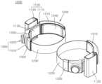
도 5는 도 3에 도시한 근력 보조 로봇에 있어서 허벅지 고정유닛을 개략적으로 도시한 사시도이고, 도 6은 도 5에 도시한 허벅지 고정유닛에 있어서, 허벅지 벨트 결합부가 해제된 상태를 개략적으로 도시한 구성도이고, 도 7은 도 6에 도시한 허벅지 고정유닛의 개략적인 평면도이다.Figure 5 is a perspective view schematically showing the thigh fixing unit in the strength assistance robot shown in Figure 3, and Figure 6 is a schematic diagram showing the thigh fixing unit shown in Figure 5 in a state in which the thigh belt coupling portion is released. It is a configuration diagram, and Figure 7 is a schematic plan view of the thigh fixing unit shown in Figure 6.
도시한 바와 같이, 허벅지 고정유닛(1000)은 어퍼 레그 프레임(도 3에 6a으로 도시함)에 각각 장착되는 한 쌍으로 이루어진다.As shown, the
보다 구체적으로, 허벅지 고정유닛(1000)은 메인 허벅지 지지부(1100), 제1 서브 허벅지 지지부(1200) 및 제2 서브 허벅지 지지부(1300)를 포함한다.More specifically, the
그리고 메인 허벅지 지지부(1100)의 일측에는 제1 서브 허벅지 지지부(1200)가 결합되고, 메인 허벅지 지지부(1100)의 타측에는 제2 서브 허벅지 지지부(1300)가 결합된다.And the first
즉, 메인 허벅지 지지부(1100)를 중심으로 양측에는 제1 서브 허벅지 지지부(1200)와 제2 서브 허벅지 지지부(1300)가 결합된다.That is, the first
또한, 메인 허벅지 지지부(1100)는 메인 허벅지 프레임(1110)과 레그 결합 프레임(1120)을 포함한다.Additionally, the main
그리고 메인 허벅지 프레임(1110)의 중심부 외측에는 레그 결합 프레임(1120)이 장착된다.And a
또한, 레그 결합 프레임(1120)은 어퍼 레그 프레임(도 3에 6a로 도시함)에 결합되기 위한 것으로, 어퍼 레그 프레임이 삽입결합 되도록 중공부(1121)가 형성될 수 있다.In addition, the
그리고 제1 서브 허벅지 지지부(1200)는 제1 서브 허벅지 프레임(1210), 허벅지 벨트 결합부(1220) 및 허벅지 벨트(1230)를 포함한다.And the first
또한, 제1 서브 허벅지 프레임(1210)은 메인 허벅지 프레임(1110)에 힌지 결합된다.Additionally, the first
또한, 허벅지 벨트 결합부(1220)는 허벅지 벨트 결합부 바디(1221)와 래치(latch)고리 플레이트(1222)를 포함한다.Additionally, the thigh
그리고 허벅지 벨트 결합부 바디(1221)의 일단부에는 허벅지 벨트(1230)가 결합되고, 타측에는 벨트 결합 플레이트(1222)가 결합된다.And the
또한, 벨트 결합 플레이트(1222)는 제2 서브 허벅지 지지부(1300)의 허벅지 와이어 권취 구조체(1320)에 탈부착 가능하도록 결합되기 위한 것이고, 래치걸이(도 11에 1323으로 도시함)가 삽입되는 슬릿(1222a)이 형성된다.In addition, the
그리고 허벅지 벨트 결합부 바디(1221)는 허벅지 벨트(1230) 입출에 의해 의해 제1 서브 허벅지 프레임(1210)에 인출 가능하도록 결합된다.And the thigh
또한, 허벅지 벨트(1230)의 일측은 허벅지 벨트 결합부(1220)에 연결되고, 타측은 제1 서브 허벅지 지지부에 인입출 가능하도록 수납된다. 또한, 허벅지 벨트(1230)는 탄성을 갖는 재료로 이루어질 수 있다.In addition, one side of the
그리고 제2 서브 허벅지 지지부(1300)는 제2 서브 허벅지 프레임(1310) 및 허벅지 와이어 권취 구조체(1320)를 포함한다.And the second
또한, 허벅지 와이어 권취 구조체(1320)는 허벅지 벨트 결합부(1220)를 고정 또는 해제시키고, 허벅지 벨트(1230)에 연결된 허벅지 와이어(도 11에 1326로 도시함)의 권취를 조작하기 위한 것이다.In addition, the thigh
그리고 허벅지 고정유닛(1000)는 대략적으로 원통형인 허벅지에 고정되기 위한 것으로, 메인 허벅지 프레임(1110)에 제1 서브 허벅지 프레임(1210)와 제2 서브 허벅지 프레임(1310)이 결합될 경우, 전체적으로 "C"형상으로 이루어진다.And the
이를 위해 제1 서브 허벅지 프레임(1210)와 제2 서브 허벅지 프레임(1310)의 내측면은 서로 대칭된 곡면으로 이루어진다,To this end, the inner surfaces of the first
또한, 메인 허벅지 지지부(1100), 제1 서브 허벅지 지지부(1200) 및 제2 서브 허벅지 지지부(1300)에는 각각 허벅지 쿠션부(1130, 1240, 1330)가 결합된다.Additionally,
그리고 쿠션부(1130, 1240, 1330)는 사용자에게 부드러운 질감 및 쿠션감을 제공하기 위한 것으로, 소프트 폼, 쿠션시트 등으로 다양하게 구현될 수 있다.Additionally, the
또한, 상기 허벅지 쿠션부(1130, 1240, 1330)는 세척이 용이하도록 벨크로 등에 의해 탈부착 가능하도록 메인 허벅지 지지부(1100), 제1 서브 허벅지 지지부(1200) 및 제2 서브 허벅지 지지부(1300)에 결합될 수 있다.In addition, the
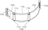
도 8는 도 6에 도시한 허벅지 고정유닛에 있어서, 메인 허벅지 지지부, 제1 서브 허벅지 지지부 및 제2 서브 허벅지 지지부의 프레임에 대한 개략적인 분해사시도이고, 도 9는 도 8에 도시한 내측 메인 허벅지 프레임, 내측 제1 서브 허벅지 프레임 및 내측 제2 서브 허벅지 프레임이 결합된 상태를 개략적으로 도시한 구성도이다.Figure 8 is a schematic exploded perspective view of the frames of the main thigh support part, the first sub thigh support part, and the second sub thigh support part in the thigh fixing unit shown in Figure 6, and Figure 9 is a schematic exploded perspective view of the inner main thigh shown in Figure 8. This is a configuration diagram schematically showing a state in which the frame, the inner first sub-thigh frame, and the inner second sub-thigh frame are combined.
도시한 바와 같이, 메인 허벅지 프레임(1110)의 양측에는 제1 서브 허벅지 프레임(1210)과 제2 서브 허벅지 프레임(1310)이 허벅지 탄성부재(1110c)에 의해 힌지 결합된다.As shown, the first
보다 구체적으로, 메인 허벅지 프레임(1110)은 내측 메인 허벅지 프레임(1110a), 외측 메인 허벅지 프레임(1110b) 및 허벅지 탄성부재(1110c)를 포함한다.More specifically, the
또한, 내측 메인 허벅지 프레임(1110a)의 일단부에는 제1 서브 허벅지 힌지 결합부인 제1 서브 허벅지 프레임 결합부(1111a)와, 제2 서브 허벅지 힌지 결합부인 제2 서브 허벅지 프레임 결합부(1112a)가 형성된다.In addition, at one end of the inner
또한, 허벅지 탄성부재(1110c)는 제1 허벅지 탄성부재(1111c)와 제2 허벅지 탄성부재(1112c)를 포함한다. 그리고 제1 허벅지 탄성부재(1111c)와 제2 허벅지 탄성부재(1112c)는 각각 양단부에 인출된 결합부가 형성되고, 원통형상으로 이루어진다.Additionally, the thigh
그리고 제1 허벅지 탄성부재(1111c)는 제1 서브 허벅지 프레임(1210)을 내측 메인 허벅지 프레임(1110a)에 탄성적으로 결합시키기 위한 것이다.And the first thigh
그리고 제2 허벅지 탄성부재(1112c)는 제2 서브 허벅지 프레임(1230)을 내측 메인 허벅지 프레임(1110a)에 탄성적으로 결합시키기 위한 것이다.And the second thigh
다음으로, 제1 서브 허벅지 프레임(1210)은 내측 제1 서브 허벅지 프레임(1210a)과 외측 제1 서브 허벅지 프레임(1210b)을 포함한다.Next, the first
또한, 내측 제1 서브 허벅지 프레임(1210a)의 일단부에는 제1 서브 허벅지 프레임 결합부(1111a)에 대응되는 제1 메인 허벅지 프레임 결합부(1211a)가 형성된다.Additionally, a first main thigh
그리고, 제2 서브 허벅지 프레임(1310)은 내측 제2 서브 허벅지 프레임(1310a)과 외측 제2 서브 허벅지 프레임(1310b)을 포함한다.And, the second
또한, 내측 제2 서브 허벅지 프레임(1310a)의 일단부에는 제2 서브 허벅지 프레임 결합부(1112a)에 대응되는 제2 메인 허벅지 프레임 결합부(1311a)가 형성된다.Additionally, a second main thigh
그리고 제1 서브 허벅지 프레임 결합부(1111a)에 제1 허벅지 탄성부재(1111c)의 일단부가 결합되고, 제1 메인 허벅지 프레임 결합부(1211a)에 제1 허벅지 탄성부재(1111c)의 타단부가 결합된 상태로, 제1 서브 허벅지 프레임 결합부(1111a)에 제1 메인 허벅지 프레임 결합부(1211a)가 결합된다.And one end of the first thigh elastic member (1111c) is coupled to the first sub thigh frame coupling portion (1111a), and the other end of the first thigh elastic member (1111c) is coupled to the first main thigh frame coupling portion (1211a). In this state, the first main thigh
이 때, 제1 서브 허벅지 프레임 결합부(1111a)에는 제1 허벅지 탄성부재(1111c)가 수용되기 위한 삽입홈이 형성될 수 있다.At this time, an insertion groove for receiving the first thigh
또한, 제2 서브 허벅지 프레임 결합부(1112a)에 제2 허벅지 탄성부재(1112c)의 일단부가 결합되고, 제2 메인 허벅지 프레임 결합부(1311a)에 제2 허벅지 탄성부재(1112c)의 타단부가 결합된 상태로, 제2 서브 허벅지 프레임 결합부(1112a)에 제2 메인 허벅지 프레임 결합부(1311a)가 결합된다.In addition, one end of the second thigh
이 때, 제2 서브 허벅지 프레임 결합부(1112a)에는 제2 허벅지 탄성부재(1112c)가 수용되기 위한 삽입홈이 형성될 수 있다.At this time, an insertion groove for receiving the second thigh
상기한 바와 같이 이루어짐에 따라, 제1 서브 허벅지 프레임(1210)과 제2 서브 허벅지 프레임(1310)은 메인 허벅지 프레임(1110)에 제1 허벅지 탄성부재(1111c)와 제2 허벅지 탄성부재(1112c)에 의해 탄성지지된 상태로 힌지 결합된다.As described above, the first
또한, 내측 제1 서브 허벅지 프레임(1210a)에는 허벅지 벨트(1230)의 인입과 인출을 위한 허벅지 벨트 인입출 홀(1212a)가 형성된다.In addition, a thigh
또한, 내측 제2 서브 허벅지 프레임(1310a)에는 허벅지 벨트 결합부(1220)의 벨트 결합 플레이트(1222)의 삽입을 위한 삽입홀(1312a)가 형성된다.Additionally, an
도 10은 도 7에 도시한 허벅지 고정유닛의 개략적인 사용상태도이다.Figure 10 is a schematic diagram of the use state of the thigh fixing unit shown in Figure 7.
도시한 바와 같이, 허벅지 고정유닛(1000)는 메인 허벅지 지지부(1100)를 중심으로 제1 서브 허벅지 지지부(1200)와 제2 서브 허벅지 지지부(1300)가 힌지 결합된다. 또한, 제1 서브 허벅지 지지부(1200)와 제2 서브 허벅지 지지부(1300)는 메인 허벅지 지지부(1100)에 허벅지 탄성부재(1110c)에 의해 탄성적으로 지지됨에 따라 도 10에 화살표로 도시한 바와 같이 회동가능하게 된다.As shown, in the
이에 따라, 사용자가 보행 보조 장치를 착용하기 위해 허벅지 고정유닛(1000)에 허벅지(T)를 화살표 방향으로 삽입할 경우, 제1 서브 허벅지 지지부(1200)와 제2 서브 허벅지 지지부(1300)는 허벅지 탄성부재(1110c)가 인장되면서 회동된다.Accordingly, when the user inserts the thigh (T) in the direction of the arrow into the
그리고 허벅지가 삽입된 이후, 허벅지 탄성부재(1110c)의 복원력에 의해 제1 서브 허벅지 지지부(1200)와 제2 서브 허벅지 지지부(1300)는 사용자의 허벅지를 감싸도록 회동된다.And after the thigh is inserted, the first
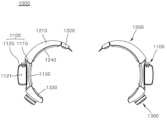
도 11는 도 5에 도시한 허벅지 고정유닛의 개략적인 단면도이고, 도 12는 도 5에 도시한 허벅지 고정유닛의 개략적인 분해사시도이다.FIG. 11 is a schematic cross-sectional view of the thigh fixing unit shown in FIG. 5, and FIG. 12 is a schematic exploded perspective view of the thigh fixing unit shown in FIG. 5.
도시한 바와 같이, 제1 서브 허벅지 지지부(1200)의 제1 서브 허벅지 프레임(1210)에는 허벅지 벨트(1230)가 수용된다.As shown, the
전술한 바와 같이, 허벅지 벨트(1230)의 일단부는 허벅지 벨트 결합부(1220)에 결합되고, 허벅지 벨트(1230)의 타단부는 허벅지 와이어(1326)에 결합된다.As described above, one end of the
또한, 허벅지 벨트 결합부(1220)는 허벅지 벨트 결합부 바디(1221)와 벨트 결합 플레이트(1222)를 포함한다. 그리고 허벅지 벨트 결합부 바디(1221)의 일단부에는 허벅지 벨트(1230)가 결합되고, 타단부에는 벨트 결합 플레이트(1222)가 결합된다.Additionally, the thigh
또한, 벨트 결합 플레이트(1222)에는 슬릿(1222a)이 형성된다.Additionally, a
또한, 제2 서브 허벅지 지지부(1300)는 제2 서브 허벅지 프레임(1310)과 허벅지 와이어 권취 구조체(1320)를 포함한다.Additionally, the second
보다 구체적으로, 허벅지 와이어 권취 구조체(1320)는 버튼식 다이얼(1321), 와이어 권취 바디(1322), 래치걸이(1323), 허벅지 와이어 권취부(1324), 판 스프링(1325) 및 허벅지 와이어(1326)를 포함한다.More specifically, the thigh
또한, 버튼식 다이얼(1321)는 와이어 권취 바디(1322)에 회동에 가능하도록 결합된다. 즉, 버튼식 다이얼(1321)는 허벅지 와이어의 권취를 위해 회동가능하도록 와이어 권취 바디(1322)에 결합된다.Additionally, the button-
그리고 와이어 권취 바디(1322)에는 벨트 결합 플레이트(1222)의 고정을 위한 래치걸이(1323)가 결합되고, 버튼식 다이얼(1321)는 와이어 권취 바디(1322)를 선형으로 이동시킴에 따라 래치걸이(1323)를 이동시킬 수 있다.And a
또한, 와이어 권취 바디(1322)에는 허벅지 와이어 권취부(1324)가 삽입결합된다.In addition, a thigh
또한, 허벅지 와이어 권취부(1324)는 원통형상으로 이루어지고 측면에 허벅지 와이어가 삽입되는 홀(1324a)이 형성되고, 중심부에 버튼식 다이얼(1321)의 이동에 따라 선택적으로 연결되기 위한 돌출부(1324b)가 형성된다.In addition, the thigh
즉, 버튼식 다이얼(1321)가 돌출부(1324b)에 결합될 경우 버튼식 다이얼(1321)의 회동에 의해 허벅지 와이어 권취부(1324)는 회동되고, 버튼식 다이얼(1321)가 돌출부(1324b)로부터 이탈될 경우, 허벅지 와이어 권취부(1324)는 버튼식 다이얼(1321)에 제약받지 않고 회동가능하게 된다.That is, when the
또한, 허벅지 와이어 권취부(1324)에는 허벅지 와이어가 결합된 판 스프링(1325)이 삽입 결합된다. 그리고 판 스프링(1325)에는 허벅지 와이어(1326)가 연결된다.In addition, a
그리고 판 스프링(1325)은 허벅지 와이어 권취부에 연결되고, 허벅지 와이어 권취부의 회동에 따라 압축 또는 복원되어 허벅지 와이어의 권취력을 제공한다. 그리고 허벅지 와이어(1326)에 연결된 허벅지 벨트(1230)는 허벅지 와이어의 이동에 연동된다.And the
도 13은 도 11에 도시한 허벅지 고정유닛의 개략적인 제1 사용상태도이다.Figure 13 is a schematic first use state diagram of the thigh fixing unit shown in Figure 11.
도시한 바와 같이, 허벅지 벨트 결합부(1220)는 제1 서브 허벅지 프레임(1210)로부터 인출되고, 래치 고리 플레이트(1222)의 슬릿(1222a)에는 허벅지 와이어 권취 구조체(1320)의 래치걸이(1323)가 삽입된다.As shown, the thigh
또한, 허벅지 와이어(1326)는 허벅지 와이어 권취부(1324)로부터 인출되고, 판 스프링(1325)는 압축된 상태가 된다.Additionally, the
그리고, 버튼식 다이얼(1321)는 허벅지 와이어 권취부(1324)의 돌출부(1324b)에 결합된 상태이다.And, the button-
이때 사용자는 허벅지 벨트(1230)의 길이를 조절하기 위해 버튼식 다이얼(1321)를 회동시키면, 버튼식 다이얼(1321)의 회동에 연동되어 허벅지 와이어 권취부(1324)는 회동되고, 허벅지 와이어(1326)는 허벅지 와이어 권취부(1324)에 감긴다.At this time, when the user rotates the
그리고 허벅지 와이어(1326)가 화살표 방향으로 이동됨에 따라 허벅지 와이어(1326)에 연결된 허벅지 벨트(1230)의 일측은 제1 서브 허벅지 프레임(1210)으로 인입된다.And as the
이에 따라, 외부로 노출된 허벅지 벨트(1230)의 길이는 조정되고, 사용자는 자신의 허벅지에 맞도록 허벅지 벨트의 길이를 조절할 수 있게 된다.Accordingly, the length of the externally exposed
또한, 허벅지의 근육은 앉아 있을 때와 서있을 때의 형상 및 크기가 상이하다. 본 발명에 따른 허벅지 고정유닛은 허벅지 벨트 결합부의 고정 이후에 허벅지 벨트의 길이조정이 가능함에 따라 사용자가 앉아서 근력 보조 로봇을 착용하고, 일어 선 상태에서 본인의 허벅지에 맞도록 허벅지 벨트의 길이를 조절할 수 있게 된다.Additionally, the shape and size of the thigh muscles are different when sitting and standing. The thigh fixing unit according to the present invention allows the length of the thigh belt to be adjusted after fixing the thigh belt joint, so that the user can sit down, wear the strength assistance robot, and adjust the length of the thigh belt to fit the user's thigh while standing up. It becomes possible.
도 14는 도 11에 도시한 허벅지 고정유닛의 개략적인 제2 사용상태도이다.Figure 14 is a schematic second use state diagram of the thigh fixing unit shown in Figure 11.
도시한 바와 같이, 사용자가 허벅지 고정유닛의 허벅지 벨트 결합부(1220)를 해제하기 위해 버튼식 다이얼(1321)를 제2 서브 허벅지 프레임(1310)의 외측방향으로 잡아당긴다.As shown, the user pulls the button-
이에 따라, 버튼식 다이얼(1321)의 인출에 연동되어, 와이어 권취 바디(1322)에 장착된 래치걸이(1323)는 래치 고리 플레이트(1222)의 슬릿(1222a)으로부터 이탈된다.Accordingly, in conjunction with the withdrawal of the
또한, 버튼식 다이얼(1321)는 인출되면서, 허벅지 와이어 권취부(1324)의 돌출부(1324b)로부터 결합 해제된다.Additionally, the
이에 따라, 판 스프링의 복원력에 의해 허벅지 와이어 권취부(1324)는 회동되고, 허벅지 와이어 권취부(1324)의 회동에 의해 허벅지 와이어는 허벅지 와이어 권취부(1324)에 감기고, 허벅지 벨트(1230)는 화살표로 도시한 바와 같이 제1 서브 허벅지 프레임(1210)의 내부로 자동으로 이동되고, 허벅지 벨트 결합부(1220)는 제1 서브 허벅지 프레임(1210)에 접하도록 이동된다.Accordingly, the thigh
상기한 바와 같이 조작됨에 따라, 사용자는 버튼식 다이얼의 간단한 조작으로 허벅지 벨트 결합부(1220)를 고정 해제하고, 허벅지 벨트는 자동으로 감김에 따라 사용자는 편리하게 근력 보조 로봇을 벗을 수 있다.As described above, the user can unfasten the thigh
또한, 허벅지 벨트(1230)는 제1 서브 허벅지 프레임(1210)에 내재됨에 따라 미사용시 허벅지 벨트의 노출에 따른 허벅지 벨트 오염, 허벅지 벨트 파손 및 미관저하의 문제점을 미연에 방지할 수 있게 된다.In addition, since the
도 15는 도 3에 도시한 근력 보조 로봇에 있어서, 종아리 고정유닛을 개략적으로 도시한 사시도이고, 도 16는 도 15에 도시한 종아리 고정유닛에 있어서, 종아리 벨트 결합부가 해제된 상태를 개략적으로 도시한 구성도이고, 도 17은 도 16에 도시한 종아리 고정유닛의 개략적인 평면도이다.FIG. 15 is a perspective view schematically showing the calf fixation unit in the muscle strength assistance robot shown in FIG. 3, and FIG. 16 schematically shows the calf fixation unit shown in FIG. 15 in a state in which the calf belt coupling portion is released. This is a configuration diagram, and FIG. 17 is a schematic plan view of the calf fixing unit shown in FIG. 16.
도시한 바와 같이 종아리 고정유닛은 허벅지 고정유닛과 동일한 구성을 포함한다.As shown, the calf fixing unit includes the same configuration as the thigh fixing unit.
보다 구체적으로, 종아리 고정유닛(2000)은 메인 종아리 지지부(2100), 제1 서브 종아리 바디부(2200) 및 제2 서브 종아리 바디부(2300)를 포함한다.More specifically, the
그리고 메인 종아리 지지부(2100)의 일측에는 제1 서브 종아리 바디부(2200)가 결합되고, 메인 종아리 지지부(2100)의 타측에는 제2 서브 종아리 바디부(2300)가 결합된다.And the first
또한, 메인 종아리 지지부(2100)는 메인 종아리 프레임(2110)과 레그 결합 프레임(2120)을 포함한다.Additionally, the main
또한, 레그 결합 프레임(2120)은 어퍼 레그 프레임이 삽입결합 되도록 중공부(2121)가 형성될 수 있다.Additionally, the
그리고 제1 서브 종아리 바디부(2200)는 제1 서브 종아리 프레임(2210), 종아리 벨트 결합부(2220) 및 종아리 벨트(2230)를 포함한다.And the first
또한, 제1 서브 종아리 프레임(2210)은 메인 종아리 프레임(2110)에 힌지결합된다.Additionally, the first
또한, 종아리 벨트 결합부(2220)는 종아리 벨트 결합부 바디(2221)와 벨트 결합 플레이트(2222)를 포함한다.Additionally, the calf
그리고 종아리 벨트 결합부 바디(2221)의 일단부에는 종아리 종아리 벨트(2230)가 결합되고, 타측에는 벨트 결합 플레이트(2222)가 결합된다.And the
또한, 벨트 결합 플레이트(2222)는 제2 서브 종아리 바디부(2300)의 종아리 와이어 권취 구조체(2320)에 탈부착 가능하도록 결합되기 위한 것이고, 래치걸이가 삽입되는 슬릿(2222a)이 형성된다.In addition, the
그리고 종아리 벨트 결합부 바디(2221)는 종아리 종아리 벨트(2230) 입출에 의해 의해 제1 서브 종아리 프레임(2210)에 인출가능하도록 결합된다.And the calf
그리고 제2 서브 종아리 바디부(2300)는 제2 서브 종아리 프레임(2310) 및 종아리 와이어 권취 구조체(2320)를 포함한다.And the second
또한, 종아리 와이어 권취 구조체(2320)는 종아리 벨트 결합부(2220)를 고정 또는 해제시키고, 종아리 벨트(2230)에 연결된 종아리 와이어의 권취를 조작하기 위한 것이다.In addition, the calf
그리고 종아리 고정유닛(2000)는 대략적으로 원통형인 종아리에 고정되기 위한 것으로, 메인 종아리 프레임(2110)에 제1 서브 종아리 프레임(2210)와 제2 서브 종아리 프레임(2310)이 결합될 경우, 전체적으로 "C"형상으로 이루어진다.In addition, the
이를 위해 제1 서브 종아리 프레임(2210)와 제2 서브 종아리 프레임(2310)의 내측면은 서로 대칭된 곡면으로 이루어진다,To this end, the inner surfaces of the first
또한, 메인 종아리 지지부(2100), 제1 서브 종아리 바디부(2200) 및 제2 서브 종아리 바디부(2300)에는 각각 종아리 쿠션부(2130, 2240, 2330)가 결합된다.In addition,
도 18은 도 16에 도시한 종아리 고정유닛에 있어서, 메인 종아리 지지부, 제1 서브 종아리 바디부 및 제2 서브 종아리 바디부의 프레임에 대한 개략적인 분해사시도이다.Figure 18 is a schematic exploded perspective view of the frame of the main calf support part, the first sub calf body part, and the second sub calf body part in the calf fixing unit shown in Figure 16.
도시한 바와 같이, 메인 종아리 프레임(2110)의 양측에는 제1 서브 종아리 프레임(2210)과 제2 서브 종아리 프레임(2310)이 종아리 탄성부재(2110c)에 의해 힌지결합된다.As shown, a first
보다 구체적으로, 메인 종아리 프레임(2110)은 내측 메인 종아리 프레임(2110a), 외측 메인 종아리 프레임(2110b) 및 종아리 탄성부재(2110c)를 포함한다.More specifically, the
또한, 내측 메인 종아리 프레임(2110a)의 일단부에는 제1 서브 종아리 프레임 결합부(2111a)와, 제2 서브 종아리 프레임 결합부(2112a)가 형성된다.Additionally, a first sub-calf
또한, 종아리 탄성부재(2110c)는 제1 종아리 탄성부재(2111c)와 제2 종아리 탄성부재(2112c)를 포함한다. 그리고 제1 종아리 탄성부재(2111c)와 제2 종아리 탄성부재(2112c)는 각각 양단부에 인출된 결합부가 형성되고, 원통형상으로 이루어진다.Additionally, the calf
그리고 제1 종아리 탄성부재(2111c)는 제1 서브 종아리 프레임을 내측 메인 종아리 프레임(2110a)에 탄성적으로 결합시키기 위한 것이다.And the first calf
그리고 제2 종아리 탄성부재(2112c)는 제2 서브 종아리 프레임을 내측 메인 종아리 프레임(2110a)에 탄성적으로 결합시키기 위한 것이다.And the second calf
다음으로, 제1 서브 종아리 프레임(2210)는 내측 제1 서브 종아리 프레임(2210a)과 외측 제1 서브 종아리 프레임(2210b)을 포함한다.Next, the first
또한, 내측 제1 서브 종아리 프레임(2210a)의 일단부에는 제1 서브 종아리 프레임 결합부(2111a)에 대응되는 제1 메인 종아리프레임 결합부(2211a)가 형성된다.Additionally, a first main calf
그리고 제2 서브 종아리 프레임(2310)은 내측 제2 서브 종아리 프레임(2310a)과 외측 제2 서브 종아리 프레임(2310b)을 포함한다.And the second
또한, 내측 제2 서브 종아리 프레임(2310a)의 일단부에는 제2 서브 종아리 프레임 결합부(2112a)에 대응되는 제2 메인 종아리 프레임 결합부(2311a)가 형성된다.Additionally, a second main calf
그리고 제1 서브 종아리 프레임 결합부(2111a)에 제1 종아리 탄성부재(2111c)의 일단부가 결합되고, 제1 메인 종아리 프레임 결합부(2211a)에 제1 종아리 탄성부재(2111c)의 타단부가 결합된 상태로, 제1 서브 종아리 프레임 결합부(2111a)에 제1 메인 종아리 프레임 결합부(2211a)가 결합된다.And one end of the first calf elastic member (2111c) is coupled to the first sub-calf frame coupling portion (2111a), and the other end of the first calf elastic member (2111c) is coupled to the first main calf frame coupling portion (2211a). In this state, the first main calf
이 때, 제1 서브 종아리 프레임 결합부(2111a)에는 제1 종아리 탄성부재(2111c)가 수용되기 위한 삽입홈이 형성될 수 있다.At this time, an insertion groove for receiving the first calf
또한, 제2 서브 종아리 프레임 결합부(2112a)에 제2 종아리 탄성부재(2112c)의 일단부가 결합되고, 제2 메인 종아리 프레임 결합부(2311a)에 제2 종아리 탄성부재(2112c)의 타단부가 결합된 상태로, 제2 서브 종아리 프레임 결합부(2112a)에 제2 메인 종아리 프레임 결합부(2311a)가 결합된다.In addition, one end of the second calf
이 때, 제2 서브 종아리 프레임 결합부(2112a)에는 제2 종아리 탄성부재(2112c)가 수용되기 위한 삽입홈이 형성될 수 있다.At this time, an insertion groove for receiving the second calf
상기한 바와 같이 이루어짐에 따라, 제1 서브 종아리 프레임(2210)과 제2 서브 종아리 프레임(2310)은 메인 종아리 프레임(2110)에 제1 종아리 탄성부재(2111c)와 제2 종아리 탄성부재(2112c)에 의해 탄성지지된 상태로 힌지 결합된다.As described above, the first
또한, 내측 제1 서브 종아리 프레임(2210a)에는 종아리 벨트(2230)의 인입과 인출을 위한 종아리 벨트 인입출 홀(2212a)가 형성된다.In addition, a calf
또한, 내측 제2 서브 종아리 프레임(2310a)에는 종아리 벨트 결합부(2220)의 벨트 결합 플레이트(2222)의 삽입을 위한 삽입홀(2312a)이 형성된다.Additionally, an
도 19는 도 15에 도시한 종아리 고정유닛의 개략적인 단면도이고, 도 20은 도 15에 도시한 종아리 고정유닛의 개략적인 분해사시도이다.FIG. 19 is a schematic cross-sectional view of the calf fixing unit shown in FIG. 15, and FIG. 20 is a schematic exploded perspective view of the calf fixing unit shown in FIG. 15.
도시한 바와 같이, 제2 서브 종아리 바디부(2300)는 제2 서브 종아리 프레임(2310)과 종아리 종아리 와이어 권취 구조체(2320)를 포함한다.As shown, the second
보다 구체적으로, 종아리 와이어 권취 구조체(2320)는 종아리 버튼식 다이얼(2321), 와이어 권취 바디(2322), 래치걸이(2323), 종아리 와이어 권취부(2324), 판 스프링(2325) 및 종아리 와이어(2326)를 포함한다.More specifically, the calf
또한, 버튼식 다이얼(2321)는 와이어 권취 바디(2322)에 회동에 가능하도록 결합된다. 즉, 버튼식 다이얼(2321)는 종아리 와이어의 권취를 위해 회동가능하도록 와이어 권취 바디(2322)에 결합된다.Additionally, the button-
그리고 와이어 권취 바디(2322)에는 와 벨트 결합 플레이트(2222)의 고정을 위한 래치걸이(2323)가 결합되고, 버튼식 다이얼(2321)는 와이어 권취 바디(2322)를 선형으로 이동시킴에 따라 래치걸이(2323)를 이동시킬 수 있다.And a
또한, 와이어 권취 바디(2322)에는 종아리 와이어 권취부(2324)가 삽입결합된다.Additionally, a calf
또한, 종아리 와이어 권취부(2324)는 원통형상으로 이루어지고 측면에 종아리 와이어가 삽입되는 홀(1324a)이 형성되고, 중심부에 버튼식 다이얼(2321)의 이동에 따라 선택적으로 연결되는 되는 돌출부(2324b)가 형성된다.In addition, the calf
즉, 버튼식 다이얼(2321)가 돌출부(2324b)에 결합될 경우 버튼식 다이얼(2321)의 회동에 의해 종아리 와이어 권취부(2324)는 회동되고, 버튼식 다이얼(2321)가 돌출부(2324b)로부터 이탈될 경우, 종아리 와이어 권취부(2324)는 버튼식 다이얼(2321)에 제약받지 않고 회동가능하게 된다.That is, when the button-
또한, 종아리 와이어 권취부(2324)에는 종아리 와이어가 결합된 판 스프링(2325)이 삽입 결합된다. 그리고 판 스프링(2325)에는 종아리 와이어(2326)가 연결된다.Additionally, a
그리고 판 스프링(2325)은 종아리 와이어(2326)의 이동에 따라 압축되고, 복원력에 의해 종아리 와이어를 이동시킨다. 그리고 종아리 와이어(2326)에 연결된 종아리 벨트(2230)는 와이어의 이동에 연동된다.And the
전술된 실시예는 모든 면에서 예시적인 것이며 한정적인 것이 아닌 것으로 이해되어야 하며, 본 발명의 범위는 전술된 상세한 설명보다는 후술될 특허청구범위에 의해 나타내어질 것이다. 그리고 후술될 특허청구범위의 의미 및 범위는 물론, 그 등가개념으로부터 도출되는 모든 변경 및 변형 가능한 형태가 본 발명의 범위에 포함되는 것으로 해석되어야 한다.The above-described embodiments should be understood in all respects as illustrative and not restrictive, and the scope of the present invention will be indicated by the claims to be described later rather than the detailed description given above. In addition, the meaning and scope of the patent claims to be described later, as well as all changes and modifications derived from the equivalent concept, should be construed as being included in the scope of the present invention.
1: 근력 보조 로봇2: 메인 컨트롤 유닛
3: 서브 컨트롤 유닛4: 메인 프레임 유닛
5: 서브 프레임 유닛6b: 레그 구동부
6: 레그 유닛6d: 로어 레그 프레임
6c: 벨트6a: 어퍼 레그 프레임
6f: 종아리 고정유닛7: 신발 고정 유닛
9: 결합 클립10: 종아리부 결합 클립
1000: 허벅지 고정유닛1100: 메인 허벅지 지지부
1110a: 내측 메인 허벅지 프레임1110: 메인 허벅지 프레임
1110b: 외측 메인 허벅지 프레임1110c: 허벅지 탄성부재
1111a: 제1 서브 허벅지 프레임 결합부1111c: 제1 허벅지 탄성부재
1112a: 제2 서브 허벅지 프레임 결합부1112c: 제2 허벅지 탄성부재
1120: 결합 프레임1121: 중공부
1200: 제1 서브 허벅지 지지부1210a: 내측 제1 서브 허벅지 프레임
1210b: 외측 제1 서브 허벅지 프레임1210: 제1 서브 허벅지 프레임
1211a: 제1 메인 허벅지 프레임 결합부1212a: 허벅지 벨트 인입출 홀
1220: 허벅지 벨트 결합부1221: 허벅지 벨트 결합부 바디
1222a: 슬릿1222: 플레이트
1230: 허벅지 벨트1300: 제2 서브 허벅지 지지부
1310a: 내측 제2 서브 허벅지 프레임1310b: 외측 제2 서브 허벅지 프레임
1310: 제2 서브 허벅지 프레임
1311a: 제2 메인 허벅지 프레임 결합부
1312a: 삽입을 위한 삽입홀1320: 허벅지 와이어 권취 구조체
1321: 버튼식 다이얼1322: 와이어 권취 바디
1323: 래치걸이1324b: 돌출부
1324a: 홀1324: 허벅지 와이어 권취부
1325: 판 스프링1326: 허벅지 와이어
2000: 종아리 고정유닛2100: 메인 종아리 지지부
2110a: 내측 메인 종아리 프레임2110: 메인 종아리 프레임
2110b: 외측 메인 종아리 프레임2110c: 종아리 탄성부재
2111a: 제1 서브 종아리 프레임 결합부2111c: 제1 종아리 탄성부재
2112a: 제2 서브 종아리 프레임 결합부2112c: 제2 종아리 탄성부재
2120: 레그 결합 프레임2121: 중공부
2200: 제1 서브 종아리 바디부2210a: 내측 제1 서브 종아리 프레임
2210b: 외측 제1 서브 종아리 프레임2210: 제1 서브 종아리 프레임
2211a: 결합부2212a: 종아리 벨트 인입출 홀
2220: 종아리 벨트 결합부2221: 종아리 벨트 결합부 바디
2222: 벨트 결합 플레이트2222a: 슬릿
2230: 종아리 벨트2300: 제2 서브 종아리 바디부
2310a: 내측 제2 서브 종아리 프레임2310b: 외측 제2 서브 종아리 프레임
2310: 제2 서브 종아리 프레임
2311a: 제2 메인 종아리 프레임 결합부
2312a: 삽입홀
2320: 종아리 와이어 권취 구조체
2321: 버튼식 다이얼2322: 와이어 권취 바디
2323: 래치걸이2324b: 돌출부
2324: 종아리 와이어 권취부2325: 판 스프링
2326: 종아리 와이어2321: 버튼식 다이얼
1130, 1240, 1330: 허벅지 쿠션부
2130, 2240, 2330: 종아리 쿠션부1: Strength assistance robot 2: Main control unit
3: Sub-control unit 4: Main frame unit
5:
6:
6c:
6f: Calf fixing unit 7: Shoe fixing unit
9: Combination clip 10: Calf joint clip
1000: Thigh fixing unit 1100: Main thigh support unit
1110a: inner main thigh frame 1110: main thigh frame
1110b: Outer
1111a: first sub-thigh
1112a: Second sub-thigh
1120: combined frame 1121: hollow part
1200: first
1210b: Outer first sub-thigh frame 1210: First sub-thigh frame
1211a: First main thigh
1220: Thigh belt joint 1221: Thigh belt joint body
1222a: slit 1222: plate
1230: thigh belt 1300: second sub thigh support
1310a: inner second
1310: Second sub thigh frame
1311a: Second main thigh frame joint
1312a: Insertion hole for insertion 1320: Thigh wire winding structure
1321: Button dial 1322: Wire winding body
1323:
1324a: Hole 1324: Thigh wire winding part
1325: leaf spring 1326: thigh wire
2000: Calf fixing unit 2100: Main calf support unit
2110a: medial main calf frame 2110: main calf frame
2110b: Outer
2111a: first sub-calf
2112a: second sub-calf
2120: Leg combination frame 2121: Hollow section
2200: first
2210b: outer first sub-calf frame 2210: first sub-calf frame
2211a: Coupling
2220: calf belt joint 2221: calf belt joint body
2222:
2230: calf belt 2300: second sub-calf body part
2310a: medial second
2310: Second sub-calf frame
2311a: Second main calf frame joint
2312a: Insertion hole
2320: Calf wire winding structure
2321: Button dial 2322: Wire wound body
2323:
2324: Calf wire winding part 2325: Leaf spring
2326: Calf wire 2321: Button dial
1130, 1240, 1330: Thigh cushion part
2130, 2240, 2330: Calf cushion part
Claims (20)
Translated fromKorean상기 메인 프레임 유닛의 양단부에 각각 구비되며 사용자의 근력을 보조하는 보조력의 강약을 조절하는 서브 컨트롤 유닛;
상기 메인 프레임 유닛의 전면에 설치되어 사용자의 허리를 고정하는 서브 프레임 유닛;
상기 메인 프레임 유닛의 양단에 각각 설치되고, 하방으로 연장되도록 형성되고, 상기 사용자의 근력을 보조하는 보조력을 발생시키고, 허벅지를 고정하는 허벅지 고정유닛과 종아리를 고정하는 종아리 고정유닛을 포함하는 레그 유닛; 및
상기 레그 유닛의 하단에 설치되어 상기 사용자의 발을 지지하는 신발 고정 유닛을 포함하고,
상기 허벅지 고정유닛은 메인 허벅지 지지부와, 상기 메인 허벅지 지지부의 일측에 힌지 결합된 제1 서브 허벅지 지지부와, 상기 메인 허벅지 지지부의 타측에 힌지 결합된 제2 서브 허벅지 지지부를 포함하고,
상기 종아리 고정유닛은 메인 종아리 지지부와, 상기 메인 종아리 지지부의 일측에 힌지 결합된 제1 서브 종아리 바디부와, 상기 메인 종아리 지지부의 타측에 힌지 결합된 제2 서브 종아리 바디부를 포함하며,
상기 메인 허벅지 지지부는 제1 허벅지 탄성부재 및 제2 허벅지 탄성부재를 포함하고, 상기 제1 서브 허벅지 지지부는 제1 허벅지 탄성부재에 의해 상기 메인 허벅지 지지부에 탄성적으로 지지되고, 제2 서브 허벅지 지지부는 제2 허벅지 탄성부재에 의해 상기 메인 허벅지 지지부에 탄성적으로 지지되고,
상기 메인 종아리 지지부는 제1 종아리 탄성부재 및 제2 종아리 탄성부재를 포함하고, 상기 제1 서브 종아리 바디부는 제1 종아리 탄성부재에 의해 상기 메인 종아리 지지부에 탄성적으로 지지되고, 제2 서브 종아리 바디부는 제2 종아리 탄성부재에 의해 상기 메인 종아리 지지부에 탄성적으로 지지되고,
상기 메인 허벅지 지지부, 상기 제1 서브 허벅지 지지부, 상기 제2 서브 허벅지 지지부에는 사용자의 허벅지에 대향되는 일면에 소프트 폼 또는 쿠션시트로 이루어진 허벅지 쿠션부가 결합되고,
상기 메인 종아리 지지부, 상기 제1 서브 종아리 바디부, 상기 제2 서브 종아리 바디부에는 사용자의 종아리에 대향되는 일면에 소프트 폼 또는 쿠션시트로 이루어진 종아리 쿠션부가 결합된
근력 보조 로봇.A main frame unit formed to surround the user's pelvis;
a sub-control unit provided at each end of the main frame unit and controlling the intensity of an auxiliary force that assists the user's muscular strength;
a sub-frame unit installed in front of the main frame unit to secure the user's waist;
A leg that is installed at both ends of the main frame unit, is formed to extend downward, generates an auxiliary force to assist the user's muscle strength, and includes a thigh fixing unit for fixing the thigh and a calf fixing unit for fixing the calf. unit; and
A shoe fixing unit installed at the bottom of the leg unit to support the user's feet,
The thigh fixing unit includes a main thigh support unit, a first sub thigh support unit hinged to one side of the main thigh support unit, and a second sub thigh support unit hinged to the other side of the main thigh support unit,
The calf fixation unit includes a main calf support portion, a first sub calf body portion hinged to one side of the main calf support portion, and a second sub calf body portion hinged to the other side of the main calf support portion,
The main thigh support part includes a first thigh elastic member and a second thigh elastic member, the first sub thigh support part is elastically supported by the main thigh support part by the first thigh elastic member, and the second sub thigh support part is elastically supported on the main thigh support unit by a second thigh elastic member,
The main calf support unit includes a first calf elastic member and a second calf elastic member, the first sub-calf body part is elastically supported by the main calf support unit by the first calf elastic member, and the second sub-calf body The portion is elastically supported on the main calf support portion by a second calf elastic member,
A thigh cushion made of soft foam or a cushion sheet is coupled to the main thigh support, the first sub-thigh support, and the second sub-thigh support on a surface opposite to the user's thigh,
The main calf support part, the first sub calf body part, and the second sub calf body part are coupled to a calf cushion made of soft foam or a cushion sheet on one side opposite to the user's calf.
Muscle assist robot.
상기 메인 프레임 유닛의 양단부에 각각 구비되며 사용자의 근력을 보조하는 보조력의 강약을 조절하는 서브 컨트롤 유닛;
상기 메인 프레임 유닛의 전면에 설치되어 사용자의 허리를 고정하는 서브 프레임 유닛;
상기 메인 프레임 유닛의 양단에 각각 설치되고, 하방으로 연장되도록 형성되고, 상기 사용자의 근력을 보조하는 보조력을 발생시키고, 허벅지를 고정하는 허벅지 고정유닛과 종아리를 고정하는 종아리 고정유닛을 포함하는 레그 유닛; 및
상기 레그 유닛의 하단에 설치되어 상기 사용자의 발을 지지하는 신발 고정 유닛을 포함하고,
상기 허벅지 고정유닛은 메인 허벅지 지지부와, 상기 메인 허벅지 지지부의 일측에 힌지 결합된 제1 서브 허벅지 지지부와, 상기 메인 허벅지 지지부의 타측에 힌지 결합된 제2 서브 허벅지 지지부를 포함하고,
상기 종아리 고정유닛은 메인 종아리 지지부와, 상기 메인 종아리 지지부의 일측에 힌지 결합된 제1 서브 종아리 바디부와, 상기 메인 종아리 지지부의 타측에 힌지 결합된 제2 서브 종아리 바디부를 포함하며,
상기 메인 허벅지 지지부는
제1 서브 허벅지 힌지 결합부와 제2 서브 허벅지 힌지 결합부가 양측에 형성된 메인 허벅지 프레임을 포함하며,
상기 제1 서브 허벅지 지지부는 상기 제1 서브 허벅지 힌지 결합부에 회동가능하도록 결합되는 제1 메인 허벅지 프레임 결합부를 포함하며,
상기 제2 서브 허벅지 지지부는 상기 제2 서브 허벅지 힌지 결합부에 회동가능하도록 결합되는 제2 메인 허벅지 프레임 결합부를 포함하며,
상기 메인 허벅지 지지부는 상기 제1 메인 허벅지 프레임 결합부에 결합되는 제1 허벅지 탄성부재와, 상기 제2 메인 허벅지 프레임 결합부에 결합되는 제2 허벅지 탄성부재를 포함하고,
상기 제1 서브 허벅지 지지부는
상기 메인 허벅지 프레임에 힌지 결합되는 상기 제1 서브 허벅지 프레임과,
상기 제2 서브 허벅지 지지부에 탈부착 가능하도록 결합되는 허벅지 벨트 결합부와,
상기 허벅지 벨트 결합부에 일측이 연결되고, 상기 제1 서브 허벅지 프레임에 타측이 인입출 가능하도록 수납된 허벅지 벨트를 포함하는
근력 보조 로봇.A main frame unit formed to surround the user's pelvis;
a sub-control unit provided at each end of the main frame unit and controlling the intensity of an auxiliary force that assists the user's muscular strength;
a sub-frame unit installed in front of the main frame unit to secure the user's waist;
A leg that is installed at both ends of the main frame unit, is formed to extend downward, generates an auxiliary force to assist the user's muscle strength, and includes a thigh fixing unit for fixing the thigh and a calf fixing unit for fixing the calf. unit; and
A shoe fixing unit installed at the bottom of the leg unit to support the user's feet,
The thigh fixing unit includes a main thigh support unit, a first sub thigh support unit hinged to one side of the main thigh support unit, and a second sub thigh support unit hinged to the other side of the main thigh support unit,
The calf fixation unit includes a main calf support portion, a first sub calf body portion hinged to one side of the main calf support portion, and a second sub calf body portion hinged to the other side of the main calf support portion,
The main thigh support part
It includes a main thigh frame with a first sub-thigh hinge coupling portion and a second sub-thigh hinge coupling portion formed on both sides,
The first sub-thigh support portion includes a first main thigh frame coupling portion rotatably coupled to the first sub-thigh hinge coupling portion,
The second sub-thigh support portion includes a second main thigh frame coupling portion rotatably coupled to the second sub-thigh hinge coupling portion,
The main thigh support unit includes a first thigh elastic member coupled to the first main thigh frame coupling portion, and a second thigh elastic member coupled to the second main thigh frame coupling portion,
The first sub thigh support portion
The first sub-thigh frame hinged to the main thigh frame,
a thigh belt coupling portion detachably coupled to the second sub thigh support portion;
One side is connected to the thigh belt coupling portion, and the other side includes a thigh belt stored in the first sub-thigh frame so as to be retractable and removable.
Muscle assist robot.
상기 제2 서브 허벅지 지지부는
상기 메인 허벅지 프레임에 힌지 결합되는 제2 서브 허벅지 프레임과,
상기 허벅지 벨트 결합부를 탈부착 가능하도록 고정 또는 해제하는 허벅지 와이어 권취 구조체를 포함하고,
상기 허벅지 벨트 결합부는 슬릿이 형성된 벨트 결합 플레이트를 포함하고,
상기 허벅지 와이어 권취 구조체는 상기 슬릿에 삽입 또는 이탈되는 래치걸이를 포함하고,
상기 허벅지 와이어 권취 구조체는
상기 래치걸이가 결합된 와이어 권취 바디와,
상기 와이어 권취 바디에 회동에 가능하도록 결합된 버튼식 다이얼과,
상기 버튼식 다이얼의 이동에 따라 선택적으로 상기 버튼식 다이얼에 연결되기 위한 돌출부가 형성된 허벅지 와이어 권취부와
상기 허벅지 와이어 권취부에 일단이 연결되고 타단이 상기 허벅지 벨트에 연결되어, 상기 허벅지 와이어 권취부의 회동에 따라 감기고 풀리는 허벅지 와이어와,
상기 허벅지 와이어 권취부에 결합되고, 허벅지 와이어 권취부의 회동에 따라 압축 또는 복원되어 허벅지 와이어의 권취력을 제공하는 판 스프링을 더 포함하는
근력 보조 로봇.According to claim 4,
The second sub thigh support unit
a second sub-thigh frame hinged to the main thigh frame;
It includes a thigh wire winding structure that secures or releases the thigh belt coupling part to make it detachable,
The thigh belt coupling portion includes a belt coupling plate with a slit,
The thigh wire winding structure includes a latch hook that is inserted into or removed from the slit,
The thigh wire winding structure is
A wire winding body to which the latch hanger is coupled,
a button-type dial rotatably coupled to the wire winding body;
a thigh wire winding portion formed with a protrusion for selectively connecting to the button-type dial according to movement of the button-type dial;
a thigh wire that has one end connected to the thigh wire winding unit and the other end connected to the thigh belt, and is wound and unwound according to rotation of the thigh wire winding unit;
It is coupled to the thigh wire winding unit and is compressed or restored according to the rotation of the thigh wire winding unit, further comprising a leaf spring that provides winding force of the thigh wire.
Muscle assist robot.
상기 메인 허벅지 프레임은
내측 메인 허벅지 프레임과, 상기 내측 메인 허벅지 프레임에 결합되는 외측 메인 허벅지 프레임을 포함하고,
상기 내측 메인 허벅지 프레임의 일단부에는 상기 제1 서브 허벅지 힌지 결합부인 제1 서브 허벅지 프레임 결합부가 형성되고, 상기 내측 메인 허벅지 프레임의 타단부에는 상기 제2 서브 허벅지 힌지 결합부인 제2 서브 허벅지 프레임 결합부가 형성되고,
상기 내측 메인 허벅지 프레임에는 소프트 폼 또는 쿠션시트로 이루어진 쿠션부가 결합되고,
상기 제1 서브 허벅지 프레임은
내측 제1 서브 허벅지 프레임과, 상기 내측 제1 서브 허벅지 프레임에 결합되는 외측 제1 서브 허벅지 프레임을 포함하고,
상기 내측 제1 서브 허벅지 프레임의 일단부에는 제1 서브 허벅지 프레임 결합부에 대응되는 제1 메인 허벅지 프레임 결합부가 형성되고,
상기 내측 제1 서브 허벅지 프레임에는 소프트 폼 또는 쿠션시트로 이루어진 쿠션부가 결합되고,
상기 내측 제1 서브 허벅지 프레임에는 상기 허벅지 벨트의 인입과 인출을 위한 허벅지 벨트 인입출 홀이 형성된
근력 보조 로봇.According to claim 4,
The main thigh frame is
It includes an inner main thigh frame and an outer main thigh frame coupled to the inner main thigh frame,
A first sub-thigh frame coupling portion, which is the first sub-thigh hinge coupling portion, is formed on one end of the inner main thigh frame, and a second sub-thigh frame coupling portion, which is the second sub-thigh hinge coupling portion, is formed on the other end of the inner main thigh frame. Wealth is formed,
A cushion portion made of soft foam or cushion seat is coupled to the inner main thigh frame,
The first sub thigh frame is
It includes an inner first sub-thigh frame and an outer first sub-thigh frame coupled to the inner first sub-thigh frame,
A first main thigh frame coupling portion corresponding to the first sub thigh frame coupling portion is formed at one end of the inner first sub thigh frame,
A cushion portion made of soft foam or a cushion seat is coupled to the inner first sub-thigh frame,
The inner first sub-thigh frame is provided with a thigh belt insertion/extraction hole for inserting and withdrawing the thigh belt.
Muscle assist robot.
상기 제2 서브 허벅지 프레임은
내측 제2 서브 허벅지 프레임과, 상기 내측 제2 서브 허벅지 프레임에 결합되는 외측 제2 서브 허벅지 프레임을 포함하고,
상기 내측 제2 서브 허벅지 프레임의 일단부에는 제2 서브 허벅지 프레임 결합부에 대응되는 제2 메인 허벅지 프레임 결합부가 형성되고,
상기 내측 제2 서브 허벅지 바디 프레임에는 상기 허벅지 벨트 결합부의 벨트 결합 플레이트의 삽입을 위한 삽입홀이 형성된
근력 보조 로봇.According to claim 6,
The second sub thigh frame is
It includes an inner second sub-thigh frame and an outer second sub-thigh frame coupled to the inner second sub-thigh frame,
A second main thigh frame coupling portion corresponding to the second sub thigh frame coupling portion is formed at one end of the inner second sub thigh frame,
An insertion hole is formed in the inner second sub-thigh body frame for insertion of the belt coupling plate of the thigh belt coupling portion.
Muscle assist robot.
상기 메인 프레임 유닛의 양단부에 각각 구비되며 사용자의 근력을 보조하는 보조력의 강약을 조절하는 서브 컨트롤 유닛;
상기 메인 프레임 유닛의 전면에 설치되어 사용자의 허리를 고정하는 서브 프레임 유닛;
상기 메인 프레임 유닛의 양단에 각각 설치되고, 하방으로 연장되도록 형성되고, 상기 사용자의 근력을 보조하는 보조력을 발생시키고, 허벅지를 고정하는 허벅지 고정유닛과 종아리를 고정하는 종아리 고정유닛을 포함하는 레그 유닛; 및
상기 레그 유닛의 하단에 설치되어 상기 사용자의 발을 지지하는 신발 고정 유닛을 포함하고,
상기 허벅지 고정유닛은 메인 허벅지 지지부와, 상기 메인 허벅지 지지부의 일측에 힌지 결합된 제1 서브 허벅지 지지부와, 상기 메인 허벅지 지지부의 타측에 힌지 결합된 제2 서브 허벅지 지지부를 포함하고,
상기 종아리 고정유닛은 메인 종아리 지지부와, 상기 메인 종아리 지지부의 일측에 힌지 결합된 제1 서브 종아리 바디부와, 상기 메인 종아리 지지부의 타측에 힌지 결합된 제2 서브 종아리 바디부를 포함하며,
상기 메인 종아리 지지부는 제1 서브 종아리 프레임 결합부와 제2 서브 종아리 프레임 결합부가 양측에 형성된 메인 종아리 프레임을 포함하며,
상기 제1 서브 종아리 바디부는 상기 제1 서브 종아리 프레임 결합부에 회동가능하도록 결합되는 제1 메인 종아리 프레임 결합부가 형성되며,
상기 제2 서브 종아리 바디부는 상기 제2 서브 종아리 프레임 결합부에 회동가능하도록 결합되는 제2 메인 종아리 프레임 결합부가 형성되며,
상기 메인 종아리 지지부는 제1 메인 종아리 프레임 결합부에 결합되는 제1 종아리 탄성부재와, 상기 제2 메인 종아리 프레임 결합부에 결합되는 제2 종아리 탄성부재를 포함하는
근력 보조 로봇.A main frame unit formed to surround the user's pelvis;
a sub-control unit provided at each end of the main frame unit and controlling the intensity of an auxiliary force that assists the user's muscular strength;
a sub-frame unit installed in front of the main frame unit to secure the user's waist;
A leg that is installed at both ends of the main frame unit, is formed to extend downward, generates an auxiliary force to assist the user's muscle strength, and includes a thigh fixing unit for fixing the thigh and a calf fixing unit for fixing the calf. unit; and
A shoe fixing unit installed at the bottom of the leg unit to support the user's feet,
The thigh fixing unit includes a main thigh support unit, a first sub thigh support unit hinged to one side of the main thigh support unit, and a second sub thigh support unit hinged to the other side of the main thigh support unit,
The calf fixation unit includes a main calf support portion, a first sub calf body portion hinged to one side of the main calf support portion, and a second sub calf body portion hinged to the other side of the main calf support portion,
The main calf support unit includes a main calf frame with a first sub-calf frame coupling portion and a second sub-calf frame coupling portion formed on both sides,
The first sub-calf body part is formed with a first main calf frame coupling part that is rotatably coupled to the first sub calf frame coupling part,
The second sub-calf body part is formed with a second main calf frame coupling part that is rotatably coupled to the second sub calf frame coupling part,
The main calf support unit includes a first calf elastic member coupled to the first main calf frame coupling portion, and a second calf elastic member coupled to the second main calf frame coupling portion.
Muscle assist robot.
상기 제1 서브 종아리 바디부는
상기 메인 종아리 프레임에 힌지 결합되는 상기 제1 서브 종아리 프레임과,
상기 제2 서브 종아리 바디부에 탈부착 가능하도록 결합되는 종아리 벨트 결합부와,
상기 종아리 벨트 결합부에 일측이 연결되고, 상기 제1 서브 종아리 프레임에 타측이 인입출 가능하도록 수납된 종아리 벨트를 포함하고,
상기 제2 서브 종아리 바디부는
상기 메인 종아리 프레임에 힌지 결합되는 제2 서브 종아리 프레임과,
상기 종아리 벨트 결합부를 탈부착 가능하도록 고정 또는 해제하는 종아리 와이어 권취 구조체를 포함하고,
상기 종아리 벨트 결합부는 슬릿이 형성된 벨트 결합 플레이트를 포함하고,
상기 종아리 와이어 권취 구조체는
상기 슬릿에 삽입 또는 이탈되는 래치걸이와,
상기 래치걸이가 결합된 와이어 권취 바디와,
상기 와이어 권취 바디에 회동에 가능하도록 결합된 버튼식 다이얼과,
상기 버튼식 다이얼의 이동에 따라 선택적으로 상기 버튼식 다이얼에 연결되기 위한 돌출부가 형성된 종아리 와이어 권취부와
상기 종아리 와이어 권취부에 일단이 연결되고 타단이 상기 종아리 벨트에 연결되어, 상기 종아리 와이어 권취부의 회동에 따라 감기고 풀리는 종아리 와이어와,
상기 종아리 와이어 권취부에 결합되고, 종아리 와이어 권취부의 회동에 따라 압축 또는 복원되어 종아리 와이어의 권취력을 제공하는 판 스프링을 포함하고,
상기 메인 종아리 프레임은
내측 메인 종아리 프레임과, 상기 내측 메인 종아리 프레임에 결합되는 외측 메인 종아리 프레임을 포함하고,
상기 내측 메인 종아리 프레임의 일단부에는 상기 제1 서브 종아리 프레임 결합부가 형성되고, 상기 내측 메인 종아리 프레임의 타단부에는 상기 제2 서브 종아리 프레임 결합부가 형성되고,
상기 내측 메인 종아리 프레임에는 소프트 폼 또는 쿠션시트로 이루어진 쿠션부가 결합된
근력 보조 로봇.According to claim 8,
The first sub-calf body part
The first sub-calf frame hinged to the main calf frame,
a calf belt coupling portion detachably coupled to the second sub-calf body;
One side is connected to the calf belt coupling portion, and the other side is stored in the first sub-calf frame to be retractable and removable,
The second sub-calf body part
a second sub-calf frame hinged to the main calf frame;
It includes a calf wire winding structure that secures or releases the calf belt coupling part to make it detachable,
The calf belt coupling portion includes a belt coupling plate with a slit,
The calf wire winding structure is
A latch hook inserted into or removed from the slit,
A wire winding body to which the latch hanger is coupled,
a button-type dial rotatably coupled to the wire winding body;
A calf wire winding portion formed with a protrusion for selectively connecting to the button-type dial according to movement of the button-type dial;
A calf wire connected at one end to the calf wire winding unit and the other end connected to the calf belt, and wound and unwound as the calf wire winding unit rotates,
It is coupled to the calf wire winding unit and includes a leaf spring that is compressed or restored according to rotation of the calf wire winding unit to provide winding force of the calf wire,
The main calf frame is
It includes an inner main calf frame and an outer main calf frame coupled to the inner main calf frame,
The first sub-calf frame coupling portion is formed at one end of the inner main calf frame, and the second sub-calf frame coupling portion is formed at the other end of the inner main calf frame,
The inner main calf frame is coupled with a cushion section made of soft foam or cushion seat.
Muscle assist robot.
상기 제1 서브 종아리 프레임은
내측 제1 서브 종아리 프레임과, 상기 내측 제1 서브 종아리 프레임에 결합되는 외측 제1 서브 종아리 프레임을 포함하고,
상기 내측 제1 서브 종아리 프레임의 일단부에는 상기 제1 서브 종아리 프레임 결합부에 대응되는 상기 제1 메인 종아리 프레임 결합부가 형성되고,
상기 내측 제1 서브 종아리 프레임에는 소프트 폼 또는 쿠션시트로 이루어진 쿠션부가 결합되고,
상기 내측 제1 서브 종아리 프레임에는 상기 종아리 벨트의 인입과 인출을 위한 종아리 벨트 인입출 홀이 형성되고,
상기 제2 서브 종아리 프레임은
내측 제2 서브 종아리 프레임과, 상기 내측 제2 서브 종아리 프레임에 결합되는 외측 제2 서브 종아리 프레임을 포함하고,
상기 내측 제2 서브 종아리 프레임의 일단부에는 상기 제2 서브 종아리 프레임 결합부에 대응되는 상기 제2 메인 종아리 프레임 결합부가 형성되고,
상기 내측 제2 서브 종아리 프레임에는 상기 종아리 벨트 결합부의 상기 벨트 결합 플레이트의 삽입을 위한 삽입홀이 형성된
근력 보조 로봇.
According to clause 9,
The first sub-calf frame is
It includes a first inner sub-calf frame and an outer first sub-calf frame coupled to the inner first sub-calf frame,
The first main calf frame coupling portion corresponding to the first sub calf frame coupling portion is formed at one end of the inner first sub calf frame,
A cushion portion made of soft foam or cushion seat is coupled to the inner first sub-calf frame,
A calf belt insertion/extraction hole is formed in the inner first sub-calf frame for inserting and withdrawing the calf belt,
The second sub-calf frame is
It includes a second inner sub-calf frame and a second outer sub-calf frame coupled to the inner second sub-calf frame,
The second main calf frame coupling portion corresponding to the second sub calf frame coupling portion is formed at one end of the inner second sub calf frame,
An insertion hole for inserting the belt coupling plate of the calf belt coupling portion is formed in the inner second sub-calf frame.
Muscle assist robot.
Priority Applications (1)
| Application Number | Priority Date | Filing Date | Title |
|---|---|---|---|
| KR1020180021295AKR102609740B1 (en) | 2018-02-22 | 2018-02-22 | Fixing unit for thigh, fixing unit for calf and power assisting robot having the same |
Applications Claiming Priority (1)
| Application Number | Priority Date | Filing Date | Title |
|---|---|---|---|
| KR1020180021295AKR102609740B1 (en) | 2018-02-22 | 2018-02-22 | Fixing unit for thigh, fixing unit for calf and power assisting robot having the same |
Publications (2)
| Publication Number | Publication Date |
|---|---|
| KR20190101225A KR20190101225A (en) | 2019-08-30 |
| KR102609740B1true KR102609740B1 (en) | 2023-12-04 |
Family
ID=67776291
Family Applications (1)
| Application Number | Title | Priority Date | Filing Date |
|---|---|---|---|
| KR1020180021295AActiveKR102609740B1 (en) | 2018-02-22 | 2018-02-22 | Fixing unit for thigh, fixing unit for calf and power assisting robot having the same |
Country Status (1)
| Country | Link |
|---|---|
| KR (1) | KR102609740B1 (en) |
Families Citing this family (4)
| Publication number | Priority date | Publication date | Assignee | Title |
|---|---|---|---|---|
| KR102265666B1 (en)* | 2020-10-27 | 2021-06-16 | 금오공과대학교 산학협력단 | Muscle force assisting device of the exoskeleton robot |
| KR20220130481A (en) | 2021-03-18 | 2022-09-27 | 삼성전자주식회사 | Electronic device and method for photographing an image using the angle of view of the camera module |
| CN113001526A (en)* | 2021-04-26 | 2021-06-22 | 倪诚 | Framework for wearable exoskeleton and transmission structure thereof |
| KR102675177B1 (en)* | 2023-11-20 | 2024-06-13 | 코스모로보틱스 주식회사 | Assist control system |
Family Cites Families (2)
| Publication number | Priority date | Publication date | Assignee | Title |
|---|---|---|---|---|
| KR101099521B1 (en)* | 2009-12-24 | 2011-12-27 | 한국산재의료원 | Wearable walking assistance robot suit |
| KR101290173B1 (en)* | 2011-10-26 | 2013-07-30 | 한양대학교 에리카산학협력단 | Wearable robot to assist muscular strength |
- 2018
- 2018-02-22KRKR1020180021295Apatent/KR102609740B1/enactiveActive
Also Published As
| Publication number | Publication date |
|---|---|
| KR20190101225A (en) | 2019-08-30 |
Similar Documents
| Publication | Publication Date | Title |
|---|---|---|
| KR102609740B1 (en) | Fixing unit for thigh, fixing unit for calf and power assisting robot having the same | |
| JP5161036B2 (en) | Walking assist device | |
| JP4326580B2 (en) | Walking assistance device thigh orthosis | |
| KR101146112B1 (en) | Power-driven walking supporting device | |
| US20190254914A1 (en) | Leg belt to effectively support the leg and wearable assistive device having the same | |
| CN113908435B (en) | Joint support device with electrode pad unit | |
| KR20190108861A (en) | Fixing unit for thigh, fixing unit for calf and wearable robot having the same | |
| JP2010012249A (en) | Lumbar traction apparatus | |
| KR102549443B1 (en) | Fixing unit for thigh, fixing unit for calf and power assisting robot having the same | |
| JP2008546460A (en) | Processing equipment for the human body | |
| JP4930826B2 (en) | Nursing aid | |
| JP6142350B1 (en) | Lower body assist device and lower body assist method | |
| KR102547246B1 (en) | Power assisting robot having improved waist support structure | |
| KR20190101274A (en) | Leg fixing part for effectively support the leg and power assisting robot having the same | |
| JP4936564B2 (en) | Nursing aid | |
| KR200275189Y1 (en) | Exercis appliances for belt type of a straightening of human body | |
| JP2005074138A (en) | Sitting posture assisting apparatus | |
| KR102707912B1 (en) | Standing Wheelchair | |
| KR102543753B1 (en) | Power assisting robot having improved waist support structure | |
| CN119606659B (en) | Wheelchair for rehabilitation | |
| CN216754918U (en) | Active apparatus for driving affected lower limb to exercise by healthy lower limb | |
| JP2004358184A (en) | Body training apparatus and body training method | |
| JP3962869B2 (en) | Rehabilitation aid | |
| JP6160415B2 (en) | Chair for walking assist device | |
| EP4140463A1 (en) | Wearing module and motion assistance device comprising same |
Legal Events
| Date | Code | Title | Description |
|---|---|---|---|
| PA0109 | Patent application | Patent event code:PA01091R01D Comment text:Patent Application Patent event date:20180222 | |
| PG1501 | Laying open of application | ||
| PA0201 | Request for examination | Patent event code:PA02012R01D Patent event date:20210222 Comment text:Request for Examination of Application Patent event code:PA02011R01I Patent event date:20180222 Comment text:Patent Application | |
| E902 | Notification of reason for refusal | ||
| PE0902 | Notice of grounds for rejection | Comment text:Notification of reason for refusal Patent event date:20220930 Patent event code:PE09021S01D | |
| E90F | Notification of reason for final refusal | ||
| PE0902 | Notice of grounds for rejection | Comment text:Final Notice of Reason for Refusal Patent event date:20230426 Patent event code:PE09021S02D | |
| E701 | Decision to grant or registration of patent right | ||
| PE0701 | Decision of registration | Patent event code:PE07011S01D Comment text:Decision to Grant Registration Patent event date:20231025 | |
| GRNT | Written decision to grant | ||
| PR0701 | Registration of establishment | Comment text:Registration of Establishment Patent event date:20231130 Patent event code:PR07011E01D | |
| PR1002 | Payment of registration fee | Payment date:20231130 End annual number:3 Start annual number:1 | |
| PG1601 | Publication of registration |