KR102603585B1 - Charging device for cleaner - Google Patents
Charging device for cleanerDownload PDFInfo
- Publication number
- KR102603585B1 KR102603585B1KR1020160108641AKR20160108641AKR102603585B1KR 102603585 B1KR102603585 B1KR 102603585B1KR 1020160108641 AKR1020160108641 AKR 1020160108641AKR 20160108641 AKR20160108641 AKR 20160108641AKR 102603585 B1KR102603585 B1KR 102603585B1
- Authority
- KR
- South Korea
- Prior art keywords
- vacuum cleaner
- cleaner
- charging
- link member
- fixing
- Prior art date
- Legal status (The legal status is an assumption and is not a legal conclusion. Google has not performed a legal analysis and makes no representation as to the accuracy of the status listed.)
- Active
Links
Images


Classifications
- A—HUMAN NECESSITIES
- A47—FURNITURE; DOMESTIC ARTICLES OR APPLIANCES; COFFEE MILLS; SPICE MILLS; SUCTION CLEANERS IN GENERAL
- A47L—DOMESTIC WASHING OR CLEANING; SUCTION CLEANERS IN GENERAL
- A47L9/00—Details or accessories of suction cleaners, e.g. mechanical means for controlling the suction or for effecting pulsating action; Storing devices specially adapted to suction cleaners or parts thereof; Carrying-vehicles specially adapted for suction cleaners
- A47L9/0009—Storing devices ; Supports, stands or holders
- A47L9/0063—External storing devices; Stands, casings or the like for the storage of suction cleaners
- A—HUMAN NECESSITIES
- A47—FURNITURE; DOMESTIC ARTICLES OR APPLIANCES; COFFEE MILLS; SPICE MILLS; SUCTION CLEANERS IN GENERAL
- A47L—DOMESTIC WASHING OR CLEANING; SUCTION CLEANERS IN GENERAL
- A47L9/00—Details or accessories of suction cleaners, e.g. mechanical means for controlling the suction or for effecting pulsating action; Storing devices specially adapted to suction cleaners or parts thereof; Carrying-vehicles specially adapted for suction cleaners
- A47L9/28—Installation of the electric equipment, e.g. adaptation or attachment to the suction cleaner; Controlling suction cleaners by electric means
- A47L9/2868—Arrangements for power supply of vacuum cleaners or the accessories thereof
- A47L9/2873—Docking units or charging stations
- A—HUMAN NECESSITIES
- A47—FURNITURE; DOMESTIC ARTICLES OR APPLIANCES; COFFEE MILLS; SPICE MILLS; SUCTION CLEANERS IN GENERAL
- A47L—DOMESTIC WASHING OR CLEANING; SUCTION CLEANERS IN GENERAL
- A47L9/00—Details or accessories of suction cleaners, e.g. mechanical means for controlling the suction or for effecting pulsating action; Storing devices specially adapted to suction cleaners or parts thereof; Carrying-vehicles specially adapted for suction cleaners
- A47L9/32—Handles
- A47L9/322—Handles for hand-supported suction cleaners
- A—HUMAN NECESSITIES
- A47—FURNITURE; DOMESTIC ARTICLES OR APPLIANCES; COFFEE MILLS; SPICE MILLS; SUCTION CLEANERS IN GENERAL
- A47L—DOMESTIC WASHING OR CLEANING; SUCTION CLEANERS IN GENERAL
- A47L5/00—Structural features of suction cleaners
- A47L5/12—Structural features of suction cleaners with power-driven air-pumps or air-compressors, e.g. driven by motor vehicle engine vacuum
- A47L5/22—Structural features of suction cleaners with power-driven air-pumps or air-compressors, e.g. driven by motor vehicle engine vacuum with rotary fans
- A47L5/225—Convertible suction cleaners, i.e. convertible between different types thereof, e.g. from upright suction cleaners to sledge-type suction cleaners
- A—HUMAN NECESSITIES
- A47—FURNITURE; DOMESTIC ARTICLES OR APPLIANCES; COFFEE MILLS; SPICE MILLS; SUCTION CLEANERS IN GENERAL
- A47L—DOMESTIC WASHING OR CLEANING; SUCTION CLEANERS IN GENERAL
- A47L5/00—Structural features of suction cleaners
- A47L5/12—Structural features of suction cleaners with power-driven air-pumps or air-compressors, e.g. driven by motor vehicle engine vacuum
- A47L5/22—Structural features of suction cleaners with power-driven air-pumps or air-compressors, e.g. driven by motor vehicle engine vacuum with rotary fans
- A47L5/24—Hand-supported suction cleaners
- A47L5/26—Hand-supported suction cleaners with driven dust-loosening tools
- A—HUMAN NECESSITIES
- A47—FURNITURE; DOMESTIC ARTICLES OR APPLIANCES; COFFEE MILLS; SPICE MILLS; SUCTION CLEANERS IN GENERAL
- A47L—DOMESTIC WASHING OR CLEANING; SUCTION CLEANERS IN GENERAL
- A47L5/00—Structural features of suction cleaners
- A47L5/12—Structural features of suction cleaners with power-driven air-pumps or air-compressors, e.g. driven by motor vehicle engine vacuum
- A47L5/22—Structural features of suction cleaners with power-driven air-pumps or air-compressors, e.g. driven by motor vehicle engine vacuum with rotary fans
- A47L5/28—Suction cleaners with handles and nozzles fixed on the casings, e.g. wheeled suction cleaners with steering handle
- A—HUMAN NECESSITIES
- A47—FURNITURE; DOMESTIC ARTICLES OR APPLIANCES; COFFEE MILLS; SPICE MILLS; SUCTION CLEANERS IN GENERAL
- A47L—DOMESTIC WASHING OR CLEANING; SUCTION CLEANERS IN GENERAL
- A47L5/00—Structural features of suction cleaners
- A47L5/12—Structural features of suction cleaners with power-driven air-pumps or air-compressors, e.g. driven by motor vehicle engine vacuum
- A47L5/22—Structural features of suction cleaners with power-driven air-pumps or air-compressors, e.g. driven by motor vehicle engine vacuum with rotary fans
- A47L5/38—Built-in suction cleaner installations, i.e. with fixed tube system to which, at different stations, hoses can be connected
- A—HUMAN NECESSITIES
- A47—FURNITURE; DOMESTIC ARTICLES OR APPLIANCES; COFFEE MILLS; SPICE MILLS; SUCTION CLEANERS IN GENERAL
- A47L—DOMESTIC WASHING OR CLEANING; SUCTION CLEANERS IN GENERAL
- A47L9/00—Details or accessories of suction cleaners, e.g. mechanical means for controlling the suction or for effecting pulsating action; Storing devices specially adapted to suction cleaners or parts thereof; Carrying-vehicles specially adapted for suction cleaners
- A47L9/0009—Storing devices ; Supports, stands or holders
- A47L9/0018—Storing devices ; Supports, stands or holders integrated in or removably mounted upon the suction cleaner for storing parts of said suction cleaner
- A47L9/0027—Storing devices ; Supports, stands or holders integrated in or removably mounted upon the suction cleaner for storing parts of said suction cleaner specially adapted for holding the suction cleaning tools
- A—HUMAN NECESSITIES
- A47—FURNITURE; DOMESTIC ARTICLES OR APPLIANCES; COFFEE MILLS; SPICE MILLS; SUCTION CLEANERS IN GENERAL
- A47L—DOMESTIC WASHING OR CLEANING; SUCTION CLEANERS IN GENERAL
- A47L9/00—Details or accessories of suction cleaners, e.g. mechanical means for controlling the suction or for effecting pulsating action; Storing devices specially adapted to suction cleaners or parts thereof; Carrying-vehicles specially adapted for suction cleaners
- A47L9/0009—Storing devices ; Supports, stands or holders
- A47L9/0054—Stands or the like for temporary interruption of work
- A—HUMAN NECESSITIES
- A47—FURNITURE; DOMESTIC ARTICLES OR APPLIANCES; COFFEE MILLS; SPICE MILLS; SUCTION CLEANERS IN GENERAL
- A47L—DOMESTIC WASHING OR CLEANING; SUCTION CLEANERS IN GENERAL
- A47L9/00—Details or accessories of suction cleaners, e.g. mechanical means for controlling the suction or for effecting pulsating action; Storing devices specially adapted to suction cleaners or parts thereof; Carrying-vehicles specially adapted for suction cleaners
- A47L9/28—Installation of the electric equipment, e.g. adaptation or attachment to the suction cleaner; Controlling suction cleaners by electric means
- A47L9/2868—Arrangements for power supply of vacuum cleaners or the accessories thereof
- A47L9/2884—Details of arrangements of batteries or their installation
- A—HUMAN NECESSITIES
- A47—FURNITURE; DOMESTIC ARTICLES OR APPLIANCES; COFFEE MILLS; SPICE MILLS; SUCTION CLEANERS IN GENERAL
- A47L—DOMESTIC WASHING OR CLEANING; SUCTION CLEANERS IN GENERAL
- A47L9/00—Details or accessories of suction cleaners, e.g. mechanical means for controlling the suction or for effecting pulsating action; Storing devices specially adapted to suction cleaners or parts thereof; Carrying-vehicles specially adapted for suction cleaners
- A47L9/32—Handles
- A47L9/325—Handles for wheeled suction cleaners with steering handle
- H—ELECTRICITY
- H01—ELECTRIC ELEMENTS
- H01M—PROCESSES OR MEANS, e.g. BATTERIES, FOR THE DIRECT CONVERSION OF CHEMICAL ENERGY INTO ELECTRICAL ENERGY
- H01M10/00—Secondary cells; Manufacture thereof
- H01M10/42—Methods or arrangements for servicing or maintenance of secondary cells or secondary half-cells
- H01M10/44—Methods for charging or discharging
- H—ELECTRICITY
- H01—ELECTRIC ELEMENTS
- H01M—PROCESSES OR MEANS, e.g. BATTERIES, FOR THE DIRECT CONVERSION OF CHEMICAL ENERGY INTO ELECTRICAL ENERGY
- H01M10/00—Secondary cells; Manufacture thereof
- H01M10/42—Methods or arrangements for servicing or maintenance of secondary cells or secondary half-cells
- H01M10/46—Accumulators structurally combined with charging apparatus
- H—ELECTRICITY
- H01—ELECTRIC ELEMENTS
- H01M—PROCESSES OR MEANS, e.g. BATTERIES, FOR THE DIRECT CONVERSION OF CHEMICAL ENERGY INTO ELECTRICAL ENERGY
- H01M10/00—Secondary cells; Manufacture thereof
- H01M10/42—Methods or arrangements for servicing or maintenance of secondary cells or secondary half-cells
- H01M10/48—Accumulators combined with arrangements for measuring, testing or indicating the condition of cells, e.g. the level or density of the electrolyte
- H—ELECTRICITY
- H02—GENERATION; CONVERSION OR DISTRIBUTION OF ELECTRIC POWER
- H02J—CIRCUIT ARRANGEMENTS OR SYSTEMS FOR SUPPLYING OR DISTRIBUTING ELECTRIC POWER; SYSTEMS FOR STORING ELECTRIC ENERGY
- H02J7/00—Circuit arrangements for charging or depolarising batteries or for supplying loads from batteries
- H02J7/0042—Circuit arrangements for charging or depolarising batteries or for supplying loads from batteries characterised by the mechanical construction
- H02J7/0044—Circuit arrangements for charging or depolarising batteries or for supplying loads from batteries characterised by the mechanical construction specially adapted for holding portable devices containing batteries
- H—ELECTRICITY
- H02—GENERATION; CONVERSION OR DISTRIBUTION OF ELECTRIC POWER
- H02J—CIRCUIT ARRANGEMENTS OR SYSTEMS FOR SUPPLYING OR DISTRIBUTING ELECTRIC POWER; SYSTEMS FOR STORING ELECTRIC ENERGY
- H02J7/00—Circuit arrangements for charging or depolarising batteries or for supplying loads from batteries
- H02J7/0042—Circuit arrangements for charging or depolarising batteries or for supplying loads from batteries characterised by the mechanical construction
- H02J7/0045—Circuit arrangements for charging or depolarising batteries or for supplying loads from batteries characterised by the mechanical construction concerning the insertion or the connection of the batteries
- H—ELECTRICITY
- H02—GENERATION; CONVERSION OR DISTRIBUTION OF ELECTRIC POWER
- H02J—CIRCUIT ARRANGEMENTS OR SYSTEMS FOR SUPPLYING OR DISTRIBUTING ELECTRIC POWER; SYSTEMS FOR STORING ELECTRIC ENERGY
- H02J7/00—Circuit arrangements for charging or depolarising batteries or for supplying loads from batteries
- H02J7/0047—Circuit arrangements for charging or depolarising batteries or for supplying loads from batteries with monitoring or indicating devices or circuits
- H02J7/0048—Detection of remaining charge capacity or state of charge [SOC]
- A—HUMAN NECESSITIES
- A47—FURNITURE; DOMESTIC ARTICLES OR APPLIANCES; COFFEE MILLS; SPICE MILLS; SUCTION CLEANERS IN GENERAL
- A47L—DOMESTIC WASHING OR CLEANING; SUCTION CLEANERS IN GENERAL
- A47L5/00—Structural features of suction cleaners
- H—ELECTRICITY
- H02—GENERATION; CONVERSION OR DISTRIBUTION OF ELECTRIC POWER
- H02J—CIRCUIT ARRANGEMENTS OR SYSTEMS FOR SUPPLYING OR DISTRIBUTING ELECTRIC POWER; SYSTEMS FOR STORING ELECTRIC ENERGY
- H02J7/00—Circuit arrangements for charging or depolarising batteries or for supplying loads from batteries
- H02J7/0047—Circuit arrangements for charging or depolarising batteries or for supplying loads from batteries with monitoring or indicating devices or circuits
Landscapes
- Engineering & Computer Science (AREA)
- Mechanical Engineering (AREA)
- Power Engineering (AREA)
- Electrochemistry (AREA)
- General Chemical & Material Sciences (AREA)
- Chemical & Material Sciences (AREA)
- Chemical Kinetics & Catalysis (AREA)
- Manufacturing & Machinery (AREA)
- Robotics (AREA)
- Charge And Discharge Circuits For Batteries Or The Like (AREA)
- Electric Vacuum Cleaner (AREA)
- Electric Suction Cleaners (AREA)
- Physical Vapour Deposition (AREA)
- Secondary Cells (AREA)
- Cleaning In General (AREA)
- Filters For Electric Vacuum Cleaners (AREA)
- Battery Mounting, Suspending (AREA)
Abstract
Translated fromKoreanDescription
Translated fromKorean본 발명은 청소기의 충전대에 관한 것이다.The present invention relates to a charging base for a vacuum cleaner.
청소기는 청소 대상 영역의 먼지나 이물을 흡입하거나 닦아 청소를 수행하는 기기이다.A vacuum cleaner is a device that performs cleaning by suctioning or wiping away dust or foreign substances in the area to be cleaned.
이러한 청소기는, 사용자가 직접 청소기를 이동시키면서 청소를 수행하기 위한 수동 청소기와, 스스로 주행하면서 청소를 수행하는 자동 청소기로 구분될 수 있다. 수동 청소기는, 청소기의 형태에 따라, 캐니스터 타입의 청소기, 업라이트 타입의 청소기, 핸디형 청소기, 스틱형 청소기 등으로 구분될 수 있다.These vacuum cleaners can be divided into manual vacuum cleaners, which perform cleaning while the user moves the vacuum cleaner, and automatic vacuum cleaners, which perform cleaning while traveling on their own. Manual vacuum cleaners can be classified into canister-type cleaners, upright-type cleaners, hand-held cleaners, stick-type cleaners, etc., depending on the type of cleaner.
상술한 청소기는 충전식 배터리를 내장하도록 구성될 수 있으며, 충전식 배터리는 수시로 충전되어야만 청소기의 동작을 위한 전원을 공급할 수 있다. 따라서, 청소기는 충전식 배터리를 충전하는 동시에 청소기를 거치할 수 있는 충전대를 필요로 한다.The above-described vacuum cleaner may be configured to have a built-in rechargeable battery, and the rechargeable battery must be charged from time to time to supply power for the operation of the vacuum cleaner. Therefore, the vacuum cleaner requires a charging stand that can hold the vacuum cleaner while charging the rechargeable battery.
선행문헌인 공개특허공보 제 10-2012-0103956호에는 진공 청소기의 충전대에 대한 내용이 개시된다.Publication No. 10-2012-0103956, a prior document, discloses information about a charging base for a vacuum cleaner.
선행문헌의 진공 청소기의 충전대는 진공 청소기를 충전하는 동시에 거치하도록, 진공 청소기의 헤드를 거치하기 위한 받침대 및 진공 청소기를 충전하기 위한 충전핀이 구비된 지지대를 포함한다.The charging stand for a vacuum cleaner in the prior literature includes a stand for mounting the head of the vacuum cleaner and a support provided with a charging pin for charging the vacuum cleaner so that the vacuum cleaner can be charged and mounted at the same time.
선행문헌의 충전대는 진공 청소기를 지지하기 위하여 수직 방향으로 돌출 지지편을 포함한다. 다만, 이러한 선행문헌의 돌출 지지편은 단순히 진공 청소기의 하측에서 삽입되는 구조이므로 진공 청소기를 안정적으로 지지하기 어려운 단점이 있다.The charging stand of the prior literature includes a support piece that protrudes in a vertical direction to support the vacuum cleaner. However, since the protruding support piece of this prior literature is simply inserted from the lower side of the vacuum cleaner, it has the disadvantage of being difficult to stably support the vacuum cleaner.
본 발명이 해결하고자 하는 과제는 청소기를 거치하는 것과 별개로 청소기를 고정시킬 수 있는 별도의 고정부재를 구비하는 청소기의 충전대를 제공하는 것이다.The problem to be solved by the present invention is to provide a charging stand for a vacuum cleaner that has a separate fixing member that can hold the vacuum cleaner separately from mounting the vacuum cleaner.
본 발명의 또 다른 과제는 청소기의 상측 및 하측을 각각 별도의 부재로 고정함으로써 청소기를 안정적으로 고정할 수 있는 청소기 충전대를 제공하는 것이다.Another object of the present invention is to provide a vacuum cleaner charging stand that can stably fix the vacuum cleaner by fixing the upper and lower sides of the vacuum cleaner with separate members.
상기 과제를 해결하기 위하여, 본 발명의 일 측면에 따른 청소기의 충전대는 충전단자가 구비되는 제1본체; 상기 청소기를 지지하는 제2본체; 및 상기 청소기를 고정시키기 위한 록킹부를 포함하고, 상기 록킹부에 일 방향으로 소정의 힘이 가해지면 상기 록킹부가 일측으로 회전하여 상기 청소기와 결합함으로써 상기 청소기를 고정하고, 상기 록킹부에 타 방향으로 소정의 힘이 가해지면 상기 록킹부가 타측으로 회전함으로써 상기 청소기와의 결합이 해제된다. 상기 록킹부는 상기 청소기의 배터리 하우징을 고정시킬 수 있다.In order to solve the above problem, the charging stand of a vacuum cleaner according to one aspect of the present invention includes a first body provided with a charging terminal; a second body supporting the vacuum cleaner; and a locking part for fixing the vacuum cleaner, wherein when a predetermined force is applied to the locking part in one direction, the locking part rotates to one side and engages with the vacuum cleaner, thereby fixing the cleaner, and rotating the locking part in the other direction. When a predetermined force is applied, the locking part rotates to the other side and the connection with the vacuum cleaner is released. The locking unit may secure the battery housing of the vacuum cleaner.
청소기의 안정적으로 고정하기 위하여, 본 발명의 다른 측면에 따른 청소기 충전대는 충전단자가 구비되는 제1본체; 상기 청소기를 지지하는 제2본체; 상기 청소기의 배터리 하우징과 결합함으로써 상기 청소기를 고정시키기 위한 제1고정부재; 및 상기 청소기의 먼지통과 결합함으로써 상기 청소기를 고정시키는 제2고정부재를 포함하고, 상기 제2본체에는 상기 청소기의 먼지통과 접촉하여 상기 청소기의 이동을 가이드하는 청소기 가이드가 구비된다.
본 발명의 또 다른 측면에 따른 청소기 충전대는, 청소기를 충전하기 위한 충전단자가 구비되는 제1본체; 상기 제1본체와 연결되며, 상기 청소기를 지지하는 제2본체; 상기 제 2 본체에서 함몰되어 형성되며, 상기 청소기에서 분리된 배터리를 수용하는 배터리 수용공간; 및 상기 제1본체에 구비되며, 상기 청소기를 고정시키기 위한 록킹부를 포함하고, 상기 록킹부에 상기 청소기가 고정되면 상기 청소기가 상기 배터리 수용공간을 커버한다.In order to stably fix the vacuum cleaner, the vacuum cleaner charging stand according to another aspect of the present invention includes a first body provided with a charging terminal; a second body supporting the vacuum cleaner; a first fixing member for fixing the vacuum cleaner by engaging the battery housing of the vacuum cleaner; and a second fixing member that fixes the cleaner by engaging with the dust bin of the cleaner, and the second body is provided with a cleaner guide that contacts the dust bin of the cleaner and guides the movement of the cleaner.
A vacuum cleaner charging stand according to another aspect of the present invention includes a first body provided with a charging terminal for charging a vacuum cleaner; a second body connected to the first body and supporting the vacuum cleaner; a battery accommodating space formed by being recessed in the second body and accommodating a battery separated from the vacuum cleaner; and a locking part provided in the first main body for fixing the vacuum cleaner, and when the vacuum cleaner is fixed to the locking part, the vacuum cleaner covers the battery accommodation space.
본 발명의 실시 예에 따르면, 청소기를 거치하는 제2본체와 별개로 록킹부가 청소기의 배터리 하우징과 결합함으로써 청소기를 안정적으로 거치할 수 있다.According to an embodiment of the present invention, the locking part, separate from the second body that holds the vacuum cleaner, is combined with the battery housing of the vacuum cleaner, so that the vacuum cleaner can be stably mounted.
또한, 본 발명의 청소기 충전대에 의하면, 청소기가 청소기 가이드에 의해 가이드되는 과정에서 록킹부의 가압부를 가압하면, 록킹부가 회전함으로써 청소기와 결합할 수 있으므로 청소기를 손쉽게 고정할 수 있는 장점이 있다.In addition, according to the vacuum cleaner charging base of the present invention, when the pressing portion of the locking portion is pressed while the vacuum cleaner is guided by the vacuum cleaner guide, the locking portion rotates and engages with the vacuum cleaner, which has the advantage of easily fixing the vacuum cleaner.
또한, 본 발명의 청소기 충전대에 의하면, 록킹부에 복수의 링크 부재 및 탄성부재가 연결됨으로써 록킹부의 열린 상태 또는 닫힌 상태가 유지될 수 있으므로 사용자 편의성이 향상될 수 있다.In addition, according to the vacuum cleaner charging base of the present invention, the locking part can be maintained in an open or closed state by connecting a plurality of link members and elastic members to the locking part, thereby improving user convenience.
또한, 본 발명의 청소기 충전대에 의하면, 록킹부를 이용하여 청소기의 배터리 하우징을 고정하고 고정돌기는 청소기의 먼지통과 결합함으로써, 청소기의 상측 및 하측을 동시에 고정할 수 있으므로 청소기를 더욱 안정적으로 고정시킬 수 있다.In addition, according to the vacuum cleaner charging stand of the present invention, the battery housing of the vacuum cleaner is fixed using a locking part, and the fixing protrusion is combined with the dust bin of the vacuum cleaner, so that the upper and lower sides of the vacuum cleaner can be fixed simultaneously, making it possible to fix the vacuum cleaner more stably. there is.
또한, 상기 고정돌기는 탄성부에 의해 탄성 지지되므로 청소기의 고정홈에 삽입되기 용이하며, 상기 고정돌기는 조작버튼에 의해 청소기로부터 분리될 수 있으므로, 청소기를 청소기 충전대에 장착하거나 탈거하는 것이 용이한 장점이 있다.In addition, the fixing protrusion is elastically supported by an elastic part, so it is easy to be inserted into the fixing groove of the vacuum cleaner, and the fixing protrusion can be separated from the vacuum cleaner by using an operation button, making it easy to attach or remove the vacuum cleaner from the vacuum cleaner charging base. There is an advantage.
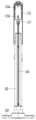
도 1은 본 발명의 일 실시 예에 따른 청소기의 충전대의 사시도이다.
도 2는 도 1의 청소기의 충전대의 정면도이다.
도 4은 도 1의 청소기의 충전대의 배면도이다.
도 5는 청소기의 충전대에 청소기가 거치된 모습을 보여주는 도면이다.
도 6의 (a)는 청소기가 지지부에 결합되는 모습을 보여주는 도면이다.
도 6의 (b)는 록킹부가 청소기에 결합되는 모습을 보여주는 도면이다.
도 18은 청소기의 충전대에서 보조 배터리가 분리된 모습을 보여주는 도면이다.
도 19은 도 18의 제2본체의 내부를 보여주는 도면이다.
도 20은 제1본체의 종단면도이다.
도 21은 충전대에서 노즐이 분리된 모습을 보여주는 도면이다.
은 충전대가 스탠드에서 분리된 모습을 보여주는 도면이다.
도 23는 청소기가 거치된 충전대가 벽면에 장착된 모습을 보여주는 도면이다.
도 24은 제1본체가 바닥면에 의해 지지되는 모습을 보여주는 도면이다.1 is a perspective view of a charging stand for a vacuum cleaner according to an embodiment of the present invention.
Figure 2 is a front view of the charging stand of the vacuum cleaner of Figure 1.
Figure 4 is a rear view of the charging stand of the vacuum cleaner of Figure 1.
Figure 5 is a diagram showing the vacuum cleaner mounted on the charging stand of the vacuum cleaner.
Figure 6(a) is a diagram showing the vacuum cleaner being coupled to the support part.
Figure 6(b) is a diagram showing the locking part being coupled to the vacuum cleaner.
Figure 18 is a diagram showing the auxiliary battery separated from the charging base of the vacuum cleaner.
FIG. 19 is a diagram showing the interior of the second body of FIG. 18.
Figure 20 is a longitudinal cross-sectional view of the first main body.
Figure 21 is a diagram showing the nozzle separated from the charging base.
This is a diagram showing the charging base separated from the stand.
Figure 23 is a diagram showing the charging station with the vacuum cleaner mounted on the wall.
Figure 24 is a view showing the first body supported by the bottom surface.
이하, 본 발명의 일부 실시 예들을 예시적인 도면을 통해 상세하게 설명한다. 각 도면의 구성요소들에 참조부호를 부가함에 있어서, 동일한 구성요소들에 대해서는 비록 다른 도면상에 표시되더라도 가능한 한 동일한 부호를 가지도록 하고 있음에 유의해야 한다. 또한, 본 발명의 실시 예를 설명함에 있어, 관련된 공지 구성 또는 기능에 대한 구체적인 설명이 본 발명의 실시예에 대한 이해를 방해한다고 판단되는 경우에는 그 상세한 설명은 생략한다.Hereinafter, some embodiments of the present invention will be described in detail through illustrative drawings. When adding reference numerals to components in each drawing, it should be noted that identical components are given the same reference numerals as much as possible even if they are shown in different drawings. Additionally, when describing embodiments of the present invention, if detailed descriptions of related known configurations or functions are judged to impede understanding of the embodiments of the present invention, the detailed descriptions will be omitted.
또한, 본 발명의 실시예의 구성 요소를 설명하는 데 있어서, 제 1, 제 2, A, B, (a), (b) 등의 용어를 사용할 수 있다. 이러한 용어는 그 구성 요소를 다른 구성 요소와 구별하기 위한 것일 뿐, 그 용어에 의해 해당 구성 요소의 본질이나 차례 또는 순서 등이 한정되지 않는다. 어떤 구성 요소가 다른 구성요소에 "연결", "결합" 또는 "접속"된다고 기재된 경우, 그 구성 요소는 그 다른 구성요소에 직접적으로 연결되거나 접속될 수 있지만, 각 구성 요소 사이에 또 다른 구성 요소가 "연결", "결합" 또는 "접속"될 수도 있다고 이해되어야 할 것이다.Additionally, in describing the components of the embodiment of the present invention, terms such as first, second, A, B, (a), and (b) may be used. These terms are only used to distinguish the component from other components, and the nature, sequence, or order of the component is not limited by the term. When a component is described as being "connected," "coupled," or "connected" to another component, that component may be directly connected or connected to that other component, but there is no need for another component between each component. It should be understood that may be “connected,” “combined,” or “connected.”
도 1은 본 발명의 일 실시 예에 따른 청소기의 충전대의 사시도이고, 도 3는 도 1의 청소기의 충전대의 정면도이고, 도 4은 도 1의 청소기의 충전대의 배면도이고, 도 5는 청소기의 충전대에 청소기가 거치된 모습을 보여주는 도면이다.FIG. 1 is a perspective view of the charging stand of the vacuum cleaner according to an embodiment of the present invention, FIG. 3 is a front view of the charging stand of the vacuum cleaner of FIG. 1, FIG. 4 is a rear view of the charging stand of the vacuum cleaner of FIG. 1, and FIG. 5 is a view of the charging stand of the vacuum cleaner of FIG. 1. This is a diagram showing the vacuum cleaner mounted on the charging stand.
도 1 내지 도 5를 참조하면, 본 발명의 일 측면에 따른 청소기의 충전대(10)는 청소기(300)를 충전하기 위한 충전대(100)를 포함한다. 상기 충전대(100)는 상기 청소기(300)를 지지하는 동시에 상기 청소기(300)에 구비된 배터리를 충전할 수 있다.Referring to Figures 1 to 5, the
상기 청소기(300)는 흡입모터가 구비된 청소기 본체(310), 배터리가 수용되는 배터리 하우징(320), 연장관(330) 및 흡입노즐(340)을 포함할 수 있다. 상기 청소기 본체(310)에서 발생한 흡입력에 의해서 외부의 공기는 상기 흡입노즐(340) 및 상기 연장관(330)을 통해 상기 청소기 본체(310)로 유입된다. 상기 청소기 본체(310)에는 상기 흡입노즐(340)을 통해 유입되는 공기에 포함된 먼지가 집진되는 먼지통(315)이 구비될 수 있다.The
상기 충전대(100)는 제1본체(110)를 포함한다.The
상기 제1본체(110)에는 제1충전단자(113)가 구비된다. 상기 제1충전단자(113)는 상기 청소기(300)의 단자와 접촉하여 상기 청소기(300)에 내장된 배터리를 충전할 수 있다.The
상기 충전대(100)는 상기 제1본체(110)와 연결되며, 보조 배터리(302)가 수용되는 제2본체(130)를 포함한다. 상기 보조 배터리(302)는 상기 청소기(300)에 탈착 가능하게 연결되어 상기 청소기(300)를 구동하기 위한 전원을 공급할 수 있다. 도시된 것과 같이, 상기 제2본체(130)는 상기 제1본체(110)와 일체로 형성될 수 있다. 상기 제2본체(130)에는 상기 보조 배터리(302)를 충전하기 위한 제2충전단자(131)(도 19 참조)가 구비될 수 있다.The
상기 제1충전단자(113)에 의한 상기 청소기(300)의 충전과, 상기 제2충전단자(131)에 의한 상기 보조 배터리(302)의 충전은 각각 독립적으로 이루어질 수 있다. 구체적으로, 상기 청소기(300)의 충전과 상기 보조 배터리(302)의 충전은 동시에 이루어지거나, 어느 하나의 충전이 이루어진 후에 나머지 하나의 충전이 이루어질 수 있다. 일례로, 상기 제1충전단자(113)에 의한 상기 청소기(300)의 배터리가 완충된 후 상기 제2충전단자(131)에 의한 상기 보조 배터리(302)의 충전이 시작될 수 있다.Charging of the
상기 제1본체(110)에는 여분의 노즐(303, 304)이 결합될 수 있다. 상기 노즐(303, 304)은 청소기 등에 탈착 가능할 수 있다. 일반적으로 청소기는 교체 가능한 흡입노즐을 용도에 따라 복수개로 구비할 수 있다. 따라서, 사용하지 않는 흡입노즐은 보관이 불편한 단점이 있으나, 이와 같이 상기 흡입노즐(303, 304)을 상기 제1본체(110)에 결합된 상태로 보관하게 되면 분실 위험이 감소하며, 사용 편의성이 향상될 수 있다. 상기 여분의 노즐(303, 304)을 "액세서리"라 이름할 수 있다.
상기 제1본체(110)에는 상기 청소기 본체(310)를 고정하기 위한 고정돌기(116)가 구비될 수 있다. 상기 고정돌기(116)는 상기 제2본체(130)에서 돌출되어 형성될 수 있다. 또한, 상기 고정돌기(116)에는 탄성부(미도시)가 연결됨으로써 외력에 의해 상기 제2본체(130)에 선택적으로 인입될 수 있다. 한편, 도시된 것과 달리 상기 고정돌기(116)는 상기 제2본체(130)가 아니라 상기 제1본체(110)에 구비될 수도 있다. 상기 고정돌기(116)를 "제2고정부재"라 이름할 수 있다.The
상기 고정돌기(116)는 상기 청소기 본체(310)에 삽입됨으로써 상기 청소기 본체(310)를 고정할 수 있다. 상기 청소기 본체(310)에는 상기 고정돌기(116)가 삽입되는 고정홈(미도시)이 형성될 수 있다.The fixing protrusion 116 may be inserted into the cleaner
한편, 도시되지 않았으나, 상기 충전대(100)에는 상기 고정돌기(116)의 인출입을 제어하기 위한 조작버튼(미도시)이 구비될 수 있다. 구체적으로, 사용자가 상기 조작버튼을 누르면 상기 고정돌기(116)가 상기 제2본체(130)로 삽입됨으로써 상기 고정돌기(116)와 상기 청소기 본체(310) 사이의 결합이 해제될 수 있다.Meanwhile, although not shown, the charging
상기 제2본체(130)에는 상기 청소기 본체(310)의 장착을 가이드하기 위한 청소기 가이드(137)가 구비될 수 있다. 상기 청소기 가이드(137)는 바닥면과 나란하게 형성될 수 있다. 상기 청소기 본체(310)는 상기 청소기 가이드(137)를 따라 후방으로 가이드되어 상기 제1충전단자(113)와 접촉할 수 있다. 상기 청소기 가이드(137)는 상기 청소기 본체(310)를 가이드하는 동시에 상기 청소기 본체(310)의 하중을 지지할 수 있다. 필요에 따라, 상기 청소기 가이드(137)를 "청소기 지지부(137)"라 이름할 수 있다.The
상기 청소기 가이드(137)의 상방에 상기 청소기(300)가 거치되는 경우, 상기 보조 배터리(302)가 외부에서 보이지 않도록 차폐될 수 있다. 도시된 것과 같이 상기 청소기 가이드(137)는 상기 제2본체(130)와 일체로 형성될 수 있으나 이와 같은 특징으로 제한되는 것은 아니다.When the
상기 고정돌기(116)는 상기 청소기 가이드(137)의 후단부 측에 구비될 수 있다. 이에 따라, 상기 청소기 본체(310)는 상기 청소기 가이드(137)를 따라 상기 제1충전단자(113) 측으로 가이드된 후 상기 고정돌기(116)와 결합할 수 있다.The fixing protrusion 116 may be provided at the rear end of the
상기 충전대(100)는 상기 제1본체(110)에 구비되는 록킹부(120)를 더 포함할 수 있다. 상기 록킹부(120)는 상기 제1본체(110)의 상측에 구비될 수 있다. 상기 록킹부(120)는 상기 청소기(300)와 결합하여 상기 청소기(300)를 안정적으로 고정할 수 있다. 상기 록킹부(120)를 "제1고정부재" 또는 "상부 고정부재"라 이름할 수 있다.The charging
구체적으로, 상기 록킹부(120)는 상기 배터리 하우징(320)과 결합하여 상기 청소기(300)를 지지할 수 있다. 상기 록킹부(120)의 내주면은 상기 배터리 하우징(320)의 외주면을 감싸도록 상기 배터리 하우징(320)의 외주면과 대응되는 형상으로 이루어질 수 있다.Specifically, the locking
사용자는 상기 록킹부(120)를 전후방으로 선택적으로 회전시켜 상기 배터리 하우징(320)과 결합시킬 수 있다. 상기 록킹부(120)에는 사용자가 파지하기 용이하도록 마찰력이 제공되는 미끄럼 방지부(122)가 구비될 수 있다. 상기 미끄럼 방지부(122)는 상기 록킹부(120)의 외주면에 돌출된 다수의 돌기를 포함할 수 있다.The user can selectively rotate the locking
상기 청소기(300) 충전대(10)는 상기 충전대(100)를 지지하기 위한 지지유닛(200)을 더 포함할 수 있다.The charging
상기 지지유닛(200)은 바닥면에 안착되는 베이스(210) 및 상기 베이스(210)에 구비되는 스탠드(220)를 포함할 수 있다. 상기 스탠드(220)는 상기 충전대(100)에 분리 가능하게 결합될 수 있다. 상기 스탠드(220)는 상기 베이스(210)와 결합하며, 연직 상방으로 연장될 수 있다.The
상기 스탠드(220)의 하단부는 상기 베이스(210)와 연결되고, 상기 스탠드(220)의 상단부는 상기 충전대(100)와 연결된다. 상기 스탠드(220)의 상단부는 상기 충전대(100)의 무게 중심(G)의 연직 하방에서 상기 충전대(100)와 연결될 수 있다. 이에 따라, 상기 스탠드(220)는 상기 충전대(100)를 안정적으로 지지할 수 있다.The lower end of the
상기 제1본체(110)에는 전원을 공급하기 위한 전선(114)이 구비될 수 있다. 상기 전선(114)은 상기 제1본체(110)의 배면(111)에서 연장된다.The
상기 제1본체(110)에는 상기 전선(114)이 연결되는 연결단자(117)가 구비될 수 있다. 상기 전선(114)의 일단부는 상기 연결단자(117)를 통해 상기 제1본체(110)와 연결될 수 있다.The
상기 연결단자(117)에는 상기 제1충전단자(113)와 상기 제2충전단자(131)가 연결된다. 이에 따라, 상기 전선(114)을 통해 인가되는 전원이 상기 제1충전단자(113) 및 상기 제2충전단자(131)에 공급될 수 있다.The
상기 연결단자(117)는 상기 제1본체(110)의 배면(111)에 구비될 수 있다. 또한, 상기 연결단자(117)는 상기 제1충전단자(113)와 상기 제2충전단자(131)의 사이에 배치될 수 있다. 즉, 상기 연결단자(117)는 상기 제1충전단자(113)의 하방에 배치되고, 상기 제2충전단자(131)는 상기 연결단자(117)의 하방에 배치될 수 있다.The
상기 전선(114)의 타단부에는 전원 플러그(미도시)가 연결될 수 있다. 상기 전원 플러그는 콘센트 등에 연결됨으로써 외부 전원을 공급받을 수 있다.A power plug (not shown) may be connected to the other end of the
상기 전선(114)은 상기 스탠드(220)와 결합할 수 있다. 구체적으로, 상기 전선(114)은 상기 스탠드(220)의 배면에 연결되어 상기 베이스(210)로 연장될 수 있다. 상기 스탠드(220)의 배면에는 상기 전선(114)을 고정하기 위한 부재가 구비될 수 있다.The
상기 전선(114)은 상기 베이스(210)의 상단을 통해 상기 베이스(210)의 내부로 연장되고, 상기 베이스(210)의 측면부 또는 저면부를 통해 다시 상기 베이스(210)의 외부로 연장될 수 있다.The
상기 베이스(210)에는 상기 전선(114)을 감기 위한 코드릴(cord reel)(미도시)이 구비될 수 있다. 구체적으로, 상기 코드릴은 상기 베이스(210)의 내부에 구비될 수 있다. 따라서, 사용자는 필요에 따라 상기 전선(114)의 연장 길이를 조절할 수 있다.The base 210 may be provided with a cord reel (not shown) for winding the
상기 베이스(210)는 상기 청소기(300)의 흡입노즐(340)이 거치되는 경사면(213) 및 상기 청소기(300)의 흡입노즐(340)의 이탈을 방지하기 위한 스토퍼(215)를 포함할 수 있다.The base 210 may include an
상기 스토퍼(215)는 상기 경사면(213)의 단부에 돌출되어 형성될 수 있다. 상기 스토퍼(215)는 상기 흡입노즐(34)이 상기 베이스(210)에 안정적으로 안착된 상태를 유지할 수 있도록 지지하는 역할을 한다.The
한편, 상기 제1본체(110)에는 먼지 수집부(미도시)가 구비될 수 있다. 상기 먼지 수집부는 상기 청소기 본체(310)에 구비된 먼지통(315)과 연통될 수 있다. 상기 먼지통(315)에 집진된 먼지는 상기 청소기 본체(310)의 흡입모터에 발생하는 흡입력 또는 상기 먼지 수집부에 구비된 별도의 장치에서 발생한 흡입력 의해 상기 먼지 수집부로 이동할 수 있다. 상기 먼지 수집부가 구비됨으로써 사용자가 상기 먼지통(315)에 집진된 먼지를 직접 비우지 않아도 되므로 사용자 편의성이 향상될 수 있다.Meanwhile, the
상기 제1본체(110)의 배면(111)에는 벽면과 일정 거리를 유지하기 위한 이격부재(미도시)가 구비될 수 있다. 상기 이격부재는 상기 제1본체(110)의 배면(111)에서 후방을 향하여 연장되어 형성될 수 있다. 상기 이격부재가 구비됨에 따라 상기 제1본체(110)가 외력에 의해 벽면에 충돌하는 현상을 방지할 수 있다.The
상기 제1본체(110)의 배면(111)에는 상기 충전대(100)를 벽면 등에 고정하기 위한 고정부(115a, 115b)가 구비될 수 있다. 이에 따라, 상기 충전대(100)는 상기 스탠드(220)에서 분리된 상태에서 벽면에 고정될 수 있다(도 23 참조). 상기 고정부(115a, 115b)는 홀 또는 홈 형상으로 이루어질 수 있다. 이에 따라, 상기 고정부(115a, 115b)에 벽면에 설치된 못 등이 삽입됨으로써, 상기 제1본체(110)가 벽면에 고정될 수 있다.The
이하에서는, 상기 충전대(10)에 상기 청소기(300)가 결합되는 방법에 대하여 설명한다.Hereinafter, a method of attaching the
도 6는 충전대에 청소기가 결합되는 모습을 보여주는 도면이다. 구체적으로, 도 6의 (a)는 청소기가 지지부에 결합되는 모습을 보여주며, 도 6의 (b)는 록킹부가 청소기에 결합되는 모습을 보여준다.Figure 6 is a diagram showing the vacuum cleaner being coupled to the charging base. Specifically, Figure 6(a) shows the cleaner being coupled to the support part, and Figure 6(b) shows the locking part being coupled to the cleaner.
도 6를 참조하면, 상기 청소기 본체(310)는 상기 청소기 가이드(137)에 지지된 상태에서 상기 청소기 가이드(137)를 따라 전후방으로 이동할 수 있다. 이에 따라, 상기 청소기 본체(310)는 상기 제1충전단자(113)와 선택적으로 접촉할 수 있다.Referring to FIG. 6 , the cleaner
상기 록킹부(120)는 상기 제1본체(110)에 소정 각도 범위 내에서 회전 가능하게 연결될 수 있다. 도 6의 (a)는 상방으로 최대한 회전한 상태를 보여준다. 상기 록킹부(120)가 상방으로 최대한 회전한 상태를 상기 록킹부(120)가 "열린 상태"라고 지칭할 수 있다. 반대로, 상기 록킹부(120)가 상기 청소기(300)와 결합된 상태를 "닫힌 상태"라 지칭할 수 있다.The
상기 록킹부(120)에는 가압부(123)가 구비될 수 있다. 상기 가압부(123)는 상기 록킹부(120)의 내측에 구비될 수 있다. 상기 가압부(123)는 상기 청소기 본체(310)가 상기 청소기 가이드(137)를 따라 이동하는 과정에서 상기 배터리 하우징(320)에 의해 가압될 수 있다.The locking
상기 배터리 하우징(320)이 상기 가압부(123)를 가압하면, 상기 록킹부(120)가 작동할 수 있다.When the
구체적으로, 상기 록킹부(120)가 작동하면, 상기 록킹부(120)는 전방으로 회전하여 상기 배터리 하우징(320)의 외주면과 결합할 수 있다. 이에 따라, 상기 록킹부(120)는 상기 배터리 하우징(320)의 적어도 일부를 커버할 수 있다.Specifically, when the
상기 록킹부(120)가 전방으로 회전하면 상기 제1본체(110)의 내부에 구비된 탄성부재는 상기 록킹부(120)가 전방으로 회전한 상태를 유지하도록 탄성력을 제공할 수 있다. 이에 따라, 상기 록킹부(120)는 상기 배터리 하우징(320)을 상기 제1본체(110)에 고정하는 역할을 할 수 있다.When the
이하에서는 상기 록킹부(120)의 세부 구성 및 작동 원리에 대하여 상세히 설명한다.Hereinafter, the detailed configuration and operating principle of the
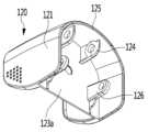
도 7은 제1본체에서 록킹부가 탈거된 모습을 보여주는 도면이고, 도 8은 록킹부의 배면을 보여주는 도면이다.Figure 7 is a diagram showing the locking part removed from the first body, and Figure 8 is a diagram showing the rear of the locking part.
도 7 및 도 8을 참조하면, 상기 록킹부(120)는 커버부(121) 및 가압부(123)를 포함한다. 상기 커버부(121)는 아치 형상으로 이루어지며, 상기 커버부(121)의 저면에는 상기 가압부(123)가 연결될 수 있다.Referring to Figures 7 and 8, the locking
상기 록킹부(120)가 상기 청소기(300)와 결합하는 경우, 상기 커버부(121)는 상기 청소기(300)의 배터리 하우징(320)의 적어도 일부를 감싼다.When the locking
상기 가압부(123)의 배면(123a)에는 상기 제1본체(110)에 회전 가능하게 결합되는 제1힌지부(124)가 구비된다.A
상기 제1힌지부(124)는 상기 제1본체(110)에 구비된 힌지 결합부(1104)와 힌지 결합된다. 이에 따라, 상기 록킹부(120)는 상기 제1힌지부(124)를 중심으로 상하 방향으로 회전할 수 있다. 도시된 것과 같이 상기 제1힌지부(124)는 한 쌍으로 구성될 수 있다.The
상기 록킹부(120)의 상측 방향의 회전 범위는 상기 록킹부(120)의 후단부(125)에 의해 제한될 수 있다. 즉, 상기 록킹부(120)가 상측 방향으로 일정 각도 이상 회전하면 상기 록킹부(120)의 후단부(125)가 상기 제1본체(110)의 일단부(상부 스토퍼)에 접촉함으로써 상기 록킹부(120)의 상측 방향의 회전 범위를 제한할 수 있다.The upward rotation range of the locking
상기 제1본체(110)에는 상기 제1충전단자(113)가 돌출되는 전면 커버(1101)가 구비된다.The
상기 전면 커버(1101)에는 상기 록킹부(120)의 하측으로의 회전 범위를 제한하기 위한 하부 스토퍼(1102)가 구비될 수 있다.The
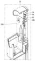
상기 전면 커버(1101)에는 개구부(1103)가 형성될 수 있다. 상기 록킹부(120)의 일부는 상기 개구부(1103)에 삽입됨으로써 상기 록킹부(120)의 작동을 위한 탄성력을 제공받을 수 있다. 상기 록킹부(120)로 탄성력을 전달하기 위해 상기 제1본체(110)의 내부에 링크 부재가 구비된다.An
상기 가압부(123)의 배면(123a)에는 상기 링크부재와 연결되는 제2힌지부(126)를 포함한다. 이하에서는, 상기 록킹부(120)의 작동 원리에 대하여 상세히 설명한다.The
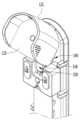
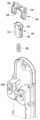
도 9는 제1본체에서 전면커버탈거된 모습을 보여주는 도면이고, 도 10은 도 9의 록킹부가 상측으로 회전한 모습을 보여주는 도면이고, 도 11은 도 9에서 록킹부가 제거된 모습을 보여주는 도면이고, 도 12는 록킹부가 상측으로 회전한 경우의 링크 부재의 모습을 보여주는 도면이고, 도 13은 도 11의 분해사시도이고, 도 14는 록킹부의 닫힌 상태에서 단면이 제1링크부재를 지나도록 절개한 충전대의 종단면도이고, 도 15는 록킹부가 닫힌 상태에서 단면이 제2링크부재를 지나도록 절개한 충전대의 종단면도이고, 도 16은 록킹부가 닫힌 상태에서 단면이 제2링크부재의 가이드부재를 지나도록 절개한 충전대의 종단면도이고, 도 17은 록킹부가 열린 상태에서의 충전대의 종단면도이다.Figure 9 is a diagram showing the front cover removed from the first body, Figure 10 is a diagram showing the locking part in Figure 9 rotated upward, and Figure 11 is a diagram showing the locking part in Figure 9 removed. , FIG. 12 is a view showing the link member when the locking portion is rotated upward, FIG. 13 is an exploded perspective view of FIG. 11, and FIG. 14 is a cross section cut through the first link member in the closed state of the locking portion. Figure 15 is a longitudinal cross-sectional view of the charging station with the locking part closed and the cross-section passing through the second link member. Figure 16 is a longitudinal cross-sectional view of the charging station with the locking part closed and the cross-section passing through the guide member of the second link member. Figure 17 is a vertical cross-sectional view of the charging stand cut in Figure 17 is a longitudinal cross-sectional view of the charging stand with the locking part open.
도 9 내지 도 17을 참조하면, 상기 제1본체(110)의 내부에는 상기 록킹부(120)와 연결되는 복수의 링크부재(140, 150)가 구비될 수 있다.Referring to FIGS. 9 to 17 , a plurality of
상기 복수의 링크부재(140, 150)는 상기 록킹부(120)와 연결되는 제1링크부재(140)와 상기 제1링크부재(140)와 연결되는 제2링크부재(150)를 포함한다.The plurality of
상기 제1링크부재(140)의 일측은 상기 록킹부(120)에 회전 가능하게 연결되고, 상기 제1링크부재(140)의 타측은 상기 제2링크부재(150)에 회전 가능하게 연결된다. 상기 제2링크부재(150)는 상기 제1본체(110) 내부에 상하로 이동 가능하게 설치된다.One side of the
상기 제1링크부재(140)는 본체부(142)와, 상기 본체부(142)에 구비되며 상기 록킹부(120)에 회전 가능하게 연결되는 제1힌지축(144) 및 상기 본체부(142)에 구비되며 상기 제2링크부재(150)에 회전 가능하게 연결되는 제2힌지축(146)을 포함할 수 있다.The
상기 제1힌지축(144)은 상기 록킹부(120)의 제2힌지부(126)와 결합할 수 있다. 이에 따라, 상기 제1링크부재(140)는 상기 록킹부(120)에 대하여 회전할 수 있다.The
상기 제2링크부재(150)는 본체부(152)와, 상기 본체부(152)에 구비되며 상기 제1링크부재(140)의 제2힌지축(146)이 결합되는 결합홈(154) 및 상기 본체부(152)에 구비되며 상기 제1본체(110)와 결합하여 상하로 이동하기 위한 가이드부재(156)를 포함할 수 있다.The
상기 결합홈(154)는 상방으로 개구된 형상으로 이루어질 수 있다. 상기 제1링크부재(140)의 제2힌지축(146)은 상기 개구된 부분을 통해 상기 결합홈(154)에 삽입될 수 있다. 이처럼, 상기 결합홈(154)는 상방으로 개구된 형상으로 이루어짐으로써 상기 제1링크부재(140)와 상기 제2링크부재(150)를 손쉽게 결합할 수 있다.The
상기 제1본체(110)에는 상기 제2링크부재(150)의 상하 방향 이동을 가이드하기 위한 가이드리브(1106)가 구비될 수 있다. 상기 가이드리브(1106)는 상하 방향으로 연장되어 형성될 수 있다. 또한, 상기 가이드리브(1106)는 상기 제2링크부재(150)의 가이드부재(156)에 삽입될 수 있다. 이에 따라, 상기 제2링크부재(150)는 상하 방향으로 이동이 가이드될 수 있다.The
한편, 도시된 것과 같이 상기 결합홈(154)과 상기 가이드부재(156)는 일체로 형성될 수 있다.Meanwhile, as shown, the
상기 제2링크부재(150)의 하방에는 탄성부재(160)가 구비될 수 있다. 상기 탄성부재(160)의 일측은 상기 제2링크부재(150)의 하방에 연결되고, 상기 탄성부재(160)의 타측은 상기 제1본체(110)에 고정된다. 상기 탄성부재(160)는 상기 제2링크부재(150)에 상방으로 탄성력을 가할 수 있다. 상기 제2링크부재(150)에는 상기 탄성부재(160)의 적어도 일부가 삽입되는 삽입홈(153)이 형성될 수 있다.An
상기 록킹부(120)가 닫힌 상태, 즉 상기 록킹부(120)가 하방으로 최대한 회전한 상태에서는 상기 제1링크부재(140)는 후방으로 최대한 회전한 상태로 유지된다. 구체적으로, 상기 제1링크부재(140)는 상기 제2링크부재(150)의 이동 궤적을 기준으로 후방으로 회전한 상태로 유지될 수 있다. 따라서, 상기 탄성부재(160)가 상기 제2링크부재(150)에 상방으로 탄성력을 가하더라도 상기 제2링크부재(150)는 상승하지 않게 된다.When the
반대로, 상기 록킹부(120)가 열릴 경우, 즉 상기 록킹부(120)가 상방으로 회전하면, 상기 제1링크부재(140)의 제1힌지축(144)은 상기 록킹부(120)를 따라 전방 상측으로 이동한다. 이 때, 상기 제1링크부재(140)의 제2힌지축(144)은 상기 제2링크부재(150)에 의해 상하 방향으로만 이동이 가능하며 전후방으로의 이동이 제한되므로 상측으로 이동한다. 상기 탄성부재(160)는 상기 제2링크부재(150)에 상방으로 탄성력을 가하므로, 상기 제1링크부재(140)의 상승에 의해 상기 제2링크부재(150)도 상기 제1링크부재(140)를 따라 상승하게 된다.Conversely, when the locking
상기 록킹부(120)가 상방으로 최대한 회전한 상태에서는 상기 탄성부재(160)의 탄성력에 의해 상기 록킹부(120)의 열린 상태가 유지될 수 있다. 이 때, 상기 록킹부(120)에 하방으로 소정의 크기 이상의 회전력을 가하면, 상기 록킹부(120)는 다시 닫힌 상태로 변경될 수 있다.When the locking
한편, 도시되지 않았으나, 상기 충전대(100)에는 상기 제2링크부재(150)를 상승 또는 하강시키기 위한 조작버튼(미도시)이 구비될 수 있다. 사용자는 상기 버튼을 조작하여, 상기 제2링크부재(150)를 자동으로 상승시킴으로써 상기 록킹부(120)를 열림 상태로 회전시키거나, 상기 제2링크부재(150)를 자동으로 하강시킴으로써 상기 록킹부(120)를 닫힘 상태로 회전시킬 수 있다.Meanwhile, although not shown, the charging
상기 록킹부(120)의 회전을 제어하기 위한 조작버튼을 "제1조작버튼"이라 이름하고, 상기 고정돌기(116)를 제어하기 위한 조작버튼을 "제2조작버튼"이라 이름 할 수 있다.The operation button for controlling the rotation of the
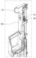
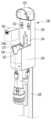
도 18은 청소기의 충전대에서 보조 배터리가 분리된 모습을 보여주는 도면이고, 도 19은 도 18의 제2본체의 내부를 보여주는 도면이고, 도 20은 제1본체의 종단면도이다.FIG. 18 is a view showing the auxiliary battery separated from the charging base of the vacuum cleaner, FIG. 19 is a view showing the interior of the second body of FIG. 18, and FIG. 20 is a longitudinal cross-sectional view of the first body.
도 18 내지 도 20을 참조하면, 상기 제2본체(130)에는 상기 보조 배터리(302)를 수용하기 위한 배터리 수용공간(130a)이 형성된다. 상기 배터리 수용공간(130a)은 상기 제2본체(130)에 하방으로 함몰되어 형성될 수 있다.Referring to FIGS. 18 to 20, a
상기 제2본체(130)의 내측에는 상기 보조 배터리(302)를 충전시키기 위한 제2충전단자(131)가 구비된다. 상기 제2충전단자(131)는 상기 제1충전단자(113) 보다 하측에 배치될 수 있다. 상기 제2충전단자(131)는 상기 제2본체(130)에 수용된 보조 배터리(302)와 선택적으로 접촉할 수 있다.A
상기 제2본체(130)에는 상기 제2충전단자(131)가 구비되는 함몰부(133)가 구비될 수 있다.The
상기 함몰부(133)는 상기 제2본체(130)의 바닥면에서 하방으로 함몰되어 형성될 수 있다. 상기 제2충전단자(131)는 상기 함몰부(133)의 바닥면에 구비되며, 상기 함몰부(133)의 바닥면으로부터 상방으로 돌출되어 형성될 수 있다.The
상기 제2충전단자(131)가 상방으로 돌출된 길이는 함몰부(133)의 깊이보다 짧게 형성될 수 있다. 이에 따라, 상기 제2충전단자(131)의 상단부는 상기 배터리 수용공간(130a)의 바닥면(130b)보다 하측에 배치될 수 있다. 즉, 상기 제2충전단자(131)는 상기 함몰부(133)에 수용되므로, 상기 제2충전단자(131)가 외력에 의해 손상되는 현상을 최소화할 수 있다.The length in which the
상기 배터리 수용공간(130a)의 일측에는 사용자가 상기 배터리 수용공간(130a)에 수용된 보조 배터리(302)를 파지하기 용이하도록 하기 위한 홈부(132, 134)가 형성될 수 있다. 사용자는 상기 홈부(132, 134)를 통해 상기 보조 배터리(302)의 측면부를 파지할 수 있다.
상기 홈부(132, 134)는 상기 배터리 수용공간(130a)의 전방에 구비되는 제1홈부(132)와, 상기 배터리 수용공간(130a)의 후방에 구비되는 제2홈부(134)를 포함할 수 있다. 상기 제1홈부(132)는 상기 제2본체(130)의 전방에 U자 형상으로 절개된 형상으로 이루어질 수 있으며, 상기 제2홈부(134)는 상기 제1본체(110)에서 후방을 향하여 함몰되어 형성될 수 있다.The
사용자는 상기 제2홈부(134)에 손가락을 삽입함으로써 상기 보조 배터리(302)의 후면부와 접촉할 수 있으며, 상기 제1홈부(132)를 통해 노출되는 상기 보조 배터리(302)의 전면부와 접촉할 수 있다. 이에 따라, 사용자는 상기 보조 배터리(302)를 파지한 상태에서, 제2본체(130)에 상기 보조 배터리(302)를 인입 또는 인출할 수 있다.The user can contact the rear part of the
상기 제1본체(110)는 상기 보조 배터리(302)의 잔량을 표시하기 위한 표시부(135)를 더 포함할 수 있다. 상기 표시부(135)는 상기 제2본체(130)에 인접하게 배치될 수 있다.The
상기 표시부(135)는 다양한 색상을 표시할 수 있는 엘이디(LED) 조명을 포함할 수 있다. 일례로, 상기 표시부(135)는 상기 보조 배터리(302)의 잔량을 3단계로 표시할 수 있다. 구체적으로, 상기 표시부(135)는 상기 보조 배터리(302)의 잔량을 상중하로 나누고 각 단계에 따라 다른 색상을 표시할 수 있다. 또한, 상기 표시부(135)는 상기 보조 배터리(302)의 충전 중에는 점멸됨으로써 충전 상태를 사용자에게 알릴 수 있다.The
상기 제2본체(130)에는 상기 보조 배터리(302)의 인출 또는 인입을 가이드하기 위한 배터리 가이드(136)가 구비될 수 있다. 상기 배터리 가이드(136)는 상기 청소기 가이드(137)의 하측에 구비되며, 하방으로 연장되어 형성될 수 있다.The
상기 배터리 가이드(136)는 상기 보조 배터리(302)와 대응되는 형상으로 이루어질 수 있다. 이에 따라, 상기 제2본체(130)로 인입되는 보조 배터리(302)의 단자의 위치가 상기 제2충전단자(131)의 위치와 정확하게 정렬될 수 있다. 도시되지 않았으나, 상기 배터리 가이드(136)에는 상기 보조 배터리(302)의 인출 또는 인입을 보다 효과적으로 가이드하기 위한 돌기 또는 홈이 형성될 수 있다.The
상기 배터리 가이드(136)에는 상기 보조 배터리(302)가 인출입되는 입구부(138)가 구비될 수 있다. 상기 입구부(138)는 상기 배터리 가이드(136)의 상방에 배치될 수 있으며, 소정의 높이를 갖도록 형성될 수 있다.The
상기 보조 배터리(302)의 삽입이 용이하도록 상기 입구부(138)는 상기 배터리 가이드(136)와 단차지도록 형성될 수 있다. 구체적으로, 상기 입구부(138)의 내주면은 상기 배터리 가이드(136)의 내주면보다 외측에 형성될 수 있다. 이에 따라 상기 입구부(138)는 상기 배터리 가이드(136)보다 넓은 폭을 갖도록 형성될 수 있다.To facilitate insertion of the
즉, 상기 배터리 가이드(136)는 상기 보조 배터리(302)와 대응되는 형상으로 이루어지므로 직접 삽입하기 어려운 문제가 있으나, 상기 배터리 가이드(136)보다 폭이 넓은 입구부(138)가 구비됨으로써 상기 보조 배터리(302)를 손쉽게 삽입할 수 있다.That is, the
상기 제2본체(130)에는 배수홀(139)이 구비될 수 있다. 상기 배수홀(139)은 상기 제2본체(130)의 저면에 형성되며 외부 공간과 연통될 수 있다. 상기 배수홀(139)은 상기 제2본체(130) 내부로 유입되는 물 등의 액체가 상기 제2본체(130) 내부에 고이는 것을 방지하기 위한 것이다. 이에 따라, 상기 충전단자(139)가 물 등의 액체에 의해 손상되는 현상을 방지할 수 있다.The
상기 배수홀(139)은 상기 함몰부(133)에 구비될 수 있으며, 상기 제2충전단자(131)와 인접하게 배치될 수 있다. 이에 따라, 상기 제2충전단자(131) 주변부에 고인 물 등의 액체가 곧바로 배수될 수 있다. 또한, 상기 배수홀(139)은 도시된 것과 달리 복수 개로 제공될 수 있다.The
도 21은 충전대에서 노즐이 분리된 모습을 보여주는 도면이다.Figure 21 is a diagram showing the nozzle separated from the charging base.
도 21을 참조하면, 상기 제1본체(110)에는 상기 여분의 노즐(303, 304)이 선택적으로 결합되는 연결부(118a, 118b)가 구비된다. 상기 연결부(118a, 118b)는 상기 제1본체(110)의 일측으로부터 연장되어 형성될 수 있다.Referring to FIG. 21, the
사용자는 필요에 따라 각각의 노즐(303, 304)을 상기 연결부(118a, 118b)에 탈착할 수 있다. 이에 따라, 상기 여분의 노즐(303, 304)의 보관 및 사용이 용이하게 되므로 사용자 편의성이 향상될 수 있다.The user can attach and detach each nozzle (303, 304) from the connecting portions (118a, 118b) as needed. Accordingly, storage and use of the
은 충전대가 스탠드에서 분리된 모습을 보여주는 도면이고, 도 23는 청소기가 거치된 충전대가 벽면에 장착된 모습을 보여주는 도면이다.is a drawing showing the charging stand separated from the stand, and Figure 23 is a drawing showing the charging stand with the vacuum cleaner mounted on the wall.
및 도 23를 참조하면, 상기 제1본체(110)에는 상기 스탠드(220)가 결합되는 결합부(119)가 형성될 수 있다. 상기 스탠드(220)는 상기 결합부(119)에 분리 가능하게 결합될 수 있다. 이에 따라, 사용자는 상기 제1본체(110)와 상기 스탠드(220)를 손쉽게 분리할 수 있다. And referring to FIG. 23, a
필요에 따라, 사용자는 상기 고정부(115a, 115b)를 이용하여 상기 제1본체(110)를 벽면(2)에 고정할 수 있다.If necessary, the user can fix the
도 24은 제1본체가 바닥면에 의해 지지되는 모습을 보여주는 도면이다.Figure 24 is a view showing the first body supported by the bottom surface.
도 24을 참조하면, 상기 제1본체(110)의 배면(111)은 바닥면에 의해 지지될 수 있다. 이를 위하여 상기 제1본체(110)의 배면(111)은 평평한 형상으로 이루어질 수 있다. 이처럼, 상기 제1본체(110)는 사용 상황에 따라 다양한 방법으로 거치될 수 있으므로, 사용자 편의성이 증대될 수 있다.Referring to FIG. 24, the
100: 충전대110: 제1본체
120: 록킹부200: 지지유닛
210: 베이스220: 스탠드
300: 청소기100: Charging stand 110: First body
120: locking unit 200: support unit
210: Base 220: Stand
300: Vacuum cleaner
Claims (18)
Translated fromKorean상기 제1본체와 연결되며, 상기 청소기를 지지하는 제2본체; 및
상기 제1본체에 회전 가능하게 연결되며, 상기 청소기의 배터리 하우징을 고정시키기 위한 록킹부를 포함하고,
상기 록킹부에 일 방향으로 소정의 힘이 가해지면 상기 록킹부가 일측으로 회전하여 상기 청소기와 결합함으로써 상기 청소기를 고정하고,
상기 록킹부에 타 방향으로 소정의 힘이 가해지면 상기 록킹부가 타측으로 회전함으로써 상기 청소기와의 결합이 해제되는 청소기 충전대.A first body provided with a charging terminal for charging the vacuum cleaner;
a second body connected to the first body and supporting the vacuum cleaner; and
It is rotatably connected to the first body and includes a locking portion for fixing the battery housing of the vacuum cleaner,
When a predetermined force is applied to the locking portion in one direction, the locking portion rotates to one side and engages the vacuum cleaner to fix the vacuum cleaner,
A vacuum cleaner charging base in which when a predetermined force is applied to the locking part in the other direction, the locking part rotates to the other side, thereby releasing the coupling with the vacuum cleaner.
상기 제1본체에는 탄성부재 및 상기 탄성부재의 탄성력을 상기 록킹부로 전달하기 위한 링크부재가 구비되며,
상기 링크부재는 상기 록킹부에 연결되어 상기 록킹부가 닫힌 상태 또는 열린 상태를 유지하도록 탄성력을 전달하는 청소기 충전대.According to claim 1,
The first body is provided with an elastic member and a link member for transmitting the elastic force of the elastic member to the locking portion,
The link member is connected to the locking unit and transmits elastic force to maintain the locking unit in a closed or open state.
상기 링크부재는 복수 개로 구비되며,
상기 복수의 링크부재는 상기 록킹부에 회전 가능하게 연결되는 제1링크부재 및
상기 제1링크부재와 연결되며, 소정의 범위 내에서 상하 방향으로 이동 가능한 제2링크부재를 포함하는 청소기 충전대.According to claim 2,
The link member is provided in plural pieces,
The plurality of link members include a first link member rotatably connected to the locking unit and
A vacuum cleaner charging stand connected to the first link member and including a second link member capable of moving up and down within a predetermined range.
상기 제1링크부재는,
상기 록킹부에 회전 가능하게 연결되는 제1힌지축 및
상기 제2링크부재에 회전 가능하게 연결되는 제2힌지축을 포함하는 청소기 충전대.According to claim 3,
The first link member is,
A first hinge shaft rotatably connected to the locking unit and
A vacuum cleaner charging stand including a second hinge shaft rotatably connected to the second link member.
상기 제2링크부재에는 상기 제2힌지축이 삽입되는 결합홈이 구비되는 청소기 충전대.According to claim 4,
A vacuum cleaner charging base wherein the second link member is provided with a coupling groove into which the second hinge shaft is inserted.
상기 결합홈은 상방으로 개구된 형상으로 이루어지는 청소기 충전대.According to claim 5,
A vacuum cleaner charging base in which the coupling groove has an upward opening shape.
상기 제2링크부재에는, 상기 제2링크부재의 상하 방향의 이동을 가이드하는 가이드부재가 구비되는 청소기 충전대.According to claim 6,
A vacuum cleaner charging stand, wherein the second link member is provided with a guide member that guides movement of the second link member in the vertical direction.
상기 탄성부재의 일측은 상기 제1본체에 결합되고, 상기 탄성부재의 타측은 상기 제2링크부재의 하측에 결합되며,
상기 탄성부재는 상기 제2링크부재에 상측으로 탄성력을 제공하는 청소기 충전대.According to claim 3,
One side of the elastic member is coupled to the first body, and the other side of the elastic member is coupled to the lower side of the second link member,
The elastic member is a vacuum cleaner charging stand that provides elastic force upward to the second link member.
상기 제2링크부재에는 상기 탄성부재의 적어도 일부가 삽입되는 삽입홈이 형성되는 청소기 충전대.According to claim 3,
A vacuum cleaner charging stand in which an insertion groove into which at least a portion of the elastic member is inserted is formed in the second link member.
상기 록킹부는,
상기 제1본체에 회전 가능하게 연결되는 제1힌지부 및
상기 제1링크부재에 회전 가능하게 연결되는 제2힌지부를 포함하는 청소기 충전대.According to claim 3,
The locking part,
A first hinge portion rotatably connected to the first body and
A vacuum cleaner charging stand including a second hinge portion rotatably connected to the first link member.
상기 록킹부에는 상기 청소기가 상기 충전단자에 접촉되는 과정에서 가압되는 가압부가 구비되며,
상기 가압부가 가압되면 상기 록킹부가 회전하여 상기 청소기와 결합하는 청소기 충전대.According to claim 1,
The locking part is provided with a pressurizing part that is pressed when the vacuum cleaner comes into contact with the charging terminal,
A vacuum cleaner charging base in which the locking part rotates and engages the vacuum cleaner when the pressing part is pressed.
상기 제2링크부재를 상승 또는 하강시키기 위한 조작버튼을 더 포함하는 청소기 충전대.According to claim 3,
A vacuum cleaner charging stand further comprising an operation button for raising or lowering the second link member.
상기 제1본체에는,
상기 록킹부의 하측 방향의 회전 범위를 제한하는 하부 스토퍼 및
상기 록킹부의 상측 방향의 회전 범위를 제한하는 상부 스토퍼가 구비되는 청소기 충전대.According to claim 1,
In the first body,
A lower stopper that limits the downward rotation range of the locking unit, and
A vacuum cleaner charging stand provided with an upper stopper that limits the upward rotation range of the locking unit.
상기 제1본체와 연결되며, 상기 청소기를 지지하는 제2본체;
상기 제1본체에 구비되며, 상기 청소기의 배터리 하우징과 결합함으로써 상기 청소기를 고정시키기 위한 제1고정부재; 및
상기 제2본체에 구비되며, 상기 청소기의 먼지통과 결합함으로써 상기 청소기를 고정시키는 제2고정부재를 포함하고,
상기 제2본체에는 상기 청소기의 먼지통과 접촉하여 상기 청소기의 이동을 가이드하는 청소기 가이드가 구비되고,
상기 제1고정부재는 상기 제1본체에 회전 가능하게 연결되며, 상기 청소기의 배터리 하우징에 결함됨으로써 상기 청소기를 고정시키는 청소기 충전대.A first body provided with a charging terminal for charging the vacuum cleaner;
a second body connected to the first body and supporting the vacuum cleaner;
a first fixing member provided on the first body and configured to fix the vacuum cleaner by engaging the battery housing of the vacuum cleaner; and
A second fixing member provided in the second body and fixing the vacuum cleaner by engaging the dust bin of the vacuum cleaner,
The second body is provided with a cleaner guide that contacts the dust bin of the cleaner and guides the movement of the cleaner,
The first fixing member is rotatably connected to the first main body and fixes the cleaner by attaching to the battery housing of the cleaner.
상기 청소기의 먼지통에는 상기 제2고정부재가 삽입되는 고정홈이 형성되며,
상기 청소기의 단자가 상기 충전단자에 접촉되면, 상기 제2고정부재는 상기 청소기의 고정홈에 삽입되어 상기 청소기를 고정시키는 청소기 충전대.According to claim 14,
A fixing groove into which the second fixing member is inserted is formed in the dust bin of the vacuum cleaner,
When the terminal of the cleaner contacts the charging terminal, the second fixing member is inserted into the fixing groove of the cleaner to fix the cleaner.
상기 제1본체와 연결되며, 상기 청소기를 지지하는 제2본체;
상기 제1본체에 구비되며, 상기 청소기의 배터리 하우징과 결합함으로써 상기 청소기를 고정시키기 위한 제1고정부재; 및
상기 제2본체에 구비되며, 상기 청소기의 먼지통과 결합함으로써 상기 청소기를 고정시키는 제2고정부재를 포함하고,
상기 제2본체에는 상기 청소기의 먼지통과 접촉하여 상기 청소기의 이동을 가이드하는 청소기 가이드가 구비되고,
상기 제2고정부재에는 탄성부가 연결되며, 상기 제2고정부재는 상기 탄성부의 탄성력에 의해 지지되는 청소기 충전대.A first body provided with a charging terminal for charging the vacuum cleaner;
a second body connected to the first body and supporting the vacuum cleaner;
a first fixing member provided on the first body and configured to fix the vacuum cleaner by engaging the battery housing of the vacuum cleaner; and
A second fixing member provided in the second body and fixing the vacuum cleaner by engaging the dust bin of the vacuum cleaner,
The second body is provided with a cleaner guide that contacts the dust bin of the cleaner and guides the movement of the cleaner,
A vacuum cleaner charging stand in which an elastic part is connected to the second fixing member, and the second fixing member is supported by the elastic force of the elastic part.
상기 제1본체와 연결되며, 상기 청소기를 지지하는 제2본체;
상기 제 2 본체에서 함몰되어 형성되며, 상기 청소기에서 분리된 배터리를 수용하는 배터리 수용공간; 및
상기 제1본체에 구비되며, 상기 청소기를 고정시키기 위한 록킹부를 포함하고,
상기 록킹부에 상기 청소기가 고정되면 상기 청소기가 상기 배터리 수용공간을 커버하는 청소기 충전대.A first body provided with a charging terminal for charging the vacuum cleaner;
a second body connected to the first body and supporting the vacuum cleaner;
a battery accommodating space formed by being recessed in the second body and accommodating a battery separated from the vacuum cleaner; and
It is provided in the first body and includes a locking part for fixing the vacuum cleaner,
A vacuum cleaner charging stand in which the vacuum cleaner covers the battery storage space when the vacuum cleaner is fixed to the locking part.
Priority Applications (14)
| Application Number | Priority Date | Filing Date | Title |
|---|---|---|---|
| JP2018558753AJP7080825B2 (en) | 2016-05-09 | 2017-05-08 | Vacuum cleaner stand |
| CN201780028291.7ACN109068921B (en) | 2016-05-09 | 2017-05-08 | Vacuum cleaner holder |
| AU2017264270AAU2017264270B2 (en) | 2016-05-09 | 2017-05-08 | Cleaner holder |
| US15/589,616US10405719B2 (en) | 2016-05-09 | 2017-05-08 | Cleaner holder |
| EP22210222.0AEP4176785B1 (en) | 2016-05-09 | 2017-05-08 | Cleaner holder |
| CN202110088034.0ACN112826365B (en) | 2016-05-09 | 2017-05-08 | Vacuum cleaner holder |
| PCT/KR2017/004740WO2017196027A1 (en) | 2016-05-09 | 2017-05-08 | Vacuum stand |
| EP20185467.6AEP3756521B1 (en) | 2016-05-09 | 2017-05-08 | Cleaner holder |
| EP17796327.9AEP3456236B1 (en) | 2016-05-09 | 2017-05-08 | Cleaner holder |
| US15/590,187US10342404B2 (en) | 2016-05-09 | 2017-05-09 | Cleaner holder |
| US15/918,080US10194779B2 (en) | 2016-05-09 | 2018-03-12 | Cleaner holder |
| US15/918,048US10299650B2 (en) | 2016-05-09 | 2018-03-12 | Cleaner holder |
| US15/918,163US10299651B2 (en) | 2016-05-09 | 2018-03-12 | Cleaner holder |
| US16/360,571US11399676B2 (en) | 2016-05-09 | 2019-03-21 | Cleaner holder |
Applications Claiming Priority (2)
| Application Number | Priority Date | Filing Date | Title |
|---|---|---|---|
| KR1020160056462 | 2016-05-09 | ||
| KR1020160056462 | 2016-05-09 |
Publications (2)
| Publication Number | Publication Date |
|---|---|
| KR20170126379A KR20170126379A (en) | 2017-11-17 |
| KR102603585B1true KR102603585B1 (en) | 2023-11-20 |
Family
ID=60808282
Family Applications (7)
| Application Number | Title | Priority Date | Filing Date |
|---|---|---|---|
| KR1020160108641AActiveKR102603585B1 (en) | 2016-05-09 | 2016-08-25 | Charging device for cleaner |
| KR1020160108639AActiveKR102626405B1 (en) | 2016-05-09 | 2016-08-25 | Charging device for cleaner |
| KR1020160108642AActiveKR102603584B1 (en) | 2016-05-09 | 2016-08-25 | Stand for Cleaner |
| KR1020160108640AActiveKR102626404B1 (en) | 2016-05-09 | 2016-08-25 | Charging device for cleaner and holder for cleaner |
| KR1020160171723AActiveKR101968588B1 (en) | 2016-05-09 | 2016-12-15 | Stand for Cleaner |
| KR1020160177828AActiveKR101832328B1 (en) | 2016-05-09 | 2016-12-23 | Charging device for cleaner |
| KR1020210044175AActiveKR102405363B1 (en) | 2016-05-09 | 2021-04-05 | Charging device for cleaner |
Family Applications After (6)
| Application Number | Title | Priority Date | Filing Date |
|---|---|---|---|
| KR1020160108639AActiveKR102626405B1 (en) | 2016-05-09 | 2016-08-25 | Charging device for cleaner |
| KR1020160108642AActiveKR102603584B1 (en) | 2016-05-09 | 2016-08-25 | Stand for Cleaner |
| KR1020160108640AActiveKR102626404B1 (en) | 2016-05-09 | 2016-08-25 | Charging device for cleaner and holder for cleaner |
| KR1020160171723AActiveKR101968588B1 (en) | 2016-05-09 | 2016-12-15 | Stand for Cleaner |
| KR1020160177828AActiveKR101832328B1 (en) | 2016-05-09 | 2016-12-23 | Charging device for cleaner |
| KR1020210044175AActiveKR102405363B1 (en) | 2016-05-09 | 2021-04-05 | Charging device for cleaner |
Country Status (8)
| Country | Link |
|---|---|
| US (4) | US10660493B2 (en) |
| EP (9) | EP3888515B1 (en) |
| JP (5) | JP6864010B2 (en) |
| KR (7) | KR102603585B1 (en) |
| CN (9) | CN109068920B (en) |
| AU (12) | AU2017262302B2 (en) |
| DE (3) | DE112017002372B4 (en) |
| TW (3) | TWI732857B (en) |
Families Citing this family (93)
| Publication number | Priority date | Publication date | Assignee | Title |
|---|---|---|---|---|
| US12156626B2 (en) | 2009-03-13 | 2024-12-03 | Omachron Intellectual Property Inc. | Surface cleaning apparatus |
| KR102335152B1 (en)* | 2014-02-28 | 2021-12-06 | 삼성전자주식회사 | Indoor unit of air-conditioner and blade unit applying the same |
| US11950745B2 (en) | 2014-12-17 | 2024-04-09 | Omachron Intellectual Property Inc. | Surface cleaning apparatus |
| WO2017196000A1 (en) | 2016-05-09 | 2017-11-16 | 엘지전자 주식회사 | Vacuum stand |
| WO2017196005A1 (en) | 2016-05-09 | 2017-11-16 | 엘지전자 주식회사 | Vacuum stand |
| US10405719B2 (en) | 2016-05-09 | 2019-09-10 | Lg Electronics Inc. | Cleaner holder |
| WO2017195999A1 (en) | 2016-05-09 | 2017-11-16 | 엘지전자 주식회사 | Vacuum stand |
| US10342404B2 (en)* | 2016-05-09 | 2019-07-09 | Lg Electronics Inc. | Cleaner holder |
| KR102603585B1 (en) | 2016-05-09 | 2023-11-20 | 엘지전자 주식회사 | Charging device for cleaner |
| WO2017196024A2 (en) | 2016-05-09 | 2017-11-16 | 엘지전자 주식회사 | Cleaner holder |
| KR102519650B1 (en)* | 2017-03-03 | 2023-04-10 | 엘지전자 주식회사 | Supporting device for cleaner and cleaner unit |
| CN109953685B (en)* | 2017-12-23 | 2024-10-22 | 天佑电器(苏州)有限公司 | Combination of dust collector and accessory frame, dust collector and accessory frame |
| GB2569821B (en)* | 2017-12-30 | 2020-04-29 | Dyson Technology Ltd | A cleaning appliance |
| CN107997677B (en)* | 2018-01-17 | 2020-02-11 | 小狗电器互联网科技(北京)股份有限公司 | Storage device of handheld dust collector |
| JP6941784B2 (en)* | 2018-03-30 | 2021-09-29 | パナソニックIpマネジメント株式会社 | Vacuum cleaner |
| JP6959177B2 (en)* | 2018-04-20 | 2021-11-02 | 日立グローバルライフソリューションズ株式会社 | Vacuum cleaner and vacuum cleaner storage |
| KR102485723B1 (en)* | 2018-05-29 | 2023-01-09 | 삼성전자주식회사 | Stand for Cleaner and Cleaning device having the same |
| MY206343A (en)* | 2018-06-22 | 2024-12-12 | Bissell Inc | Surface cleaning apparatus and tray |
| CN108695947A (en)* | 2018-07-02 | 2018-10-23 | 小狗电器互联网科技(北京)股份有限公司 | Dust catcher charging equipment and dust collecting system |
| CN108695944A (en)* | 2018-07-02 | 2018-10-23 | 小狗电器互联网科技(北京)股份有限公司 | Dust catcher charging equipment and dust collecting system |
| CN108670122B (en)* | 2018-07-02 | 2024-05-03 | 小狗电器互联网科技(北京)股份有限公司 | Dust collector charging device and dust collector charging equipment |
| CN108599338B (en)* | 2018-07-02 | 2024-02-27 | 小狗电器互联网科技(北京)股份有限公司 | Dust collector charging rack and dust collection system |
| CN108695945A (en)* | 2018-07-02 | 2018-10-23 | 小狗电器互联网科技(北京)股份有限公司 | Dust catcher charging equipment and dust collecting system |
| CN108599337A (en)* | 2018-07-02 | 2018-09-28 | 小狗电器互联网科技(北京)股份有限公司 | Dust catcher charging mechanism and dust catcher charging equipment |
| CN108736548A (en)* | 2018-07-02 | 2018-11-02 | 小狗电器互联网科技(北京)股份有限公司 | Dust catcher charging rack and dust collecting system |
| WO2020027452A1 (en) | 2018-07-30 | 2020-02-06 | 엘지전자 주식회사 | Cleaner holder and cleaner unit |
| KR102164719B1 (en)* | 2018-07-30 | 2020-10-12 | 엘지전자 주식회사 | Holder for cleaner and cleaner unit |
| USD912346S1 (en)* | 2018-08-29 | 2021-03-02 | Samsung Electronics Co., Ltd. | Stand for cleaner |
| KR102061513B1 (en)* | 2018-08-30 | 2020-01-02 | 삼성전자주식회사 | Stand for cleaner and cleaning device having the same |
| KR102557817B1 (en)* | 2018-09-04 | 2023-07-21 | 엘지전자 주식회사 | Wireless cleaner charging station and method for controlling the same |
| CN110960144A (en)* | 2018-09-28 | 2020-04-07 | 苏州凯丽达电器有限公司 | A lifting charging stand and a vacuum cleaner charging system |
| CN112911980A (en)* | 2018-10-30 | 2021-06-04 | 三菱电机株式会社 | Charging stand and electric dust collector system |
| CN109512335B (en)* | 2018-11-28 | 2021-04-20 | 苏州凯丽达电器有限公司 | Dust collector charging terminal seat with adjustable charging terminal position |
| CN109512334B (en)* | 2018-11-28 | 2021-04-20 | 苏州凯丽达电器有限公司 | Assembly of portable dust collector and charging terminal base |
| WO2020107245A1 (en)* | 2018-11-28 | 2020-06-04 | 苏州凯丽达电器有限公司 | Assembly of hand-held dust collector and charging terminal base |
| WO2020107244A1 (en)* | 2018-11-28 | 2020-06-04 | 苏州凯丽达电器有限公司 | Vacuum cleaner charging terminal base on which position of charging terminal may be adjusted |
| GB2580309B (en)* | 2018-12-24 | 2021-03-17 | Dyson Technology Ltd | Storage dock for a battery-powered vacuum cleaner |
| CN109589041B (en)* | 2018-12-29 | 2024-11-12 | 北京石头世纪科技股份有限公司 | Vacuum cleaner racks and cleaning systems |
| KR20200119063A (en)* | 2019-04-09 | 2020-10-19 | 엘지전자 주식회사 | Cleaner, charging device therefor, and cleaner package including same |
| ES2956793T3 (en) | 2019-04-18 | 2023-12-28 | Vorwerk Co Interholding | Operating procedure of a cleaning system, base station and filtration device |
| DE102019002827A1 (en)* | 2019-04-18 | 2020-10-22 | Vorwerk & Co. Interholding Gmbh | Base station and method of assembling a base station |
| CN113659657B (en)* | 2019-04-24 | 2023-08-01 | 添可智能科技有限公司 | Charging seat for dust collector and dust collector charging system |
| CN111904322B (en)* | 2019-05-07 | 2021-11-05 | 江苏美的清洁电器股份有限公司 | Dust deposition base and cleaning equipment assembly with same |
| CN110025257A (en)* | 2019-05-24 | 2019-07-19 | 苏州市伟克斯电器有限公司 | Dust catcher accepting rack and dust suction device assembly |
| KR20210015602A (en)* | 2019-07-31 | 2021-02-10 | 엘지전자 주식회사 | Cleaner |
| DE102019121524A1 (en)* | 2019-08-09 | 2021-02-11 | Miele & Cie. Kg | Wall bracket for vacuum cleaner, vacuum cleaner and floor care system |
| US11583156B2 (en) | 2019-08-14 | 2023-02-21 | Samsung Electronics Co., Ltd. | Stand for cleaner and cleaning apparatus having the same |
| KR102236107B1 (en)* | 2019-10-22 | 2021-04-05 | 프린텍 주식회사 | Hand blender comprising isolation structure of battery |
| KR20210073120A (en) | 2019-12-10 | 2021-06-18 | 엘지전자 주식회사 | Vacuum cleaner and controll method thereof |
| CN119769935A (en)* | 2019-12-31 | 2025-04-08 | 北京石头世纪科技股份有限公司 | A vacuum cleaner bracket assembly |
| WO2021143864A1 (en)* | 2020-01-16 | 2021-07-22 | 江苏美的清洁电器股份有限公司 | Storage station of vacuum cleaner, and vacuum cleaner device assembly |
| KR102865444B1 (en)* | 2020-01-17 | 2025-09-25 | 엘지전자 주식회사 | Cleaning apparatus |
| CN113317716A (en)* | 2020-02-29 | 2021-08-31 | 无锡清易智慧科技有限公司 | Vacuum cleaner docking device |
| KR102488294B1 (en)* | 2020-03-03 | 2023-01-13 | 엘지전자 주식회사 | Cleaner station, cleaner system and controlling method of cleaner station |
| WO2021177699A1 (en)* | 2020-03-03 | 2021-09-10 | 엘지전자 주식회사 | Vacuum cleaner station, vacuum cleaner system, and method for controlling vacuum cleaner station |
| KR20210019940A (en)* | 2020-06-22 | 2021-02-23 | 엘지전자 주식회사 | Station for cleaner and controlling method thereof |
| CN111329388B (en)* | 2020-04-14 | 2021-07-23 | 无锡清易智慧科技有限公司 | Hanger and dust collector accessory |
| KR20210128786A (en)* | 2020-04-17 | 2021-10-27 | 엘지전자 주식회사 | Docking station and dust removal syatem inclduing the same |
| KR102566393B1 (en)* | 2020-07-03 | 2023-08-14 | 삼성전자주식회사 | Cleaning device having vacuum cleaner and docking station |
| CN111920347B (en)* | 2020-08-12 | 2021-08-20 | 义乌市巨界机械设备有限公司 | Integrated automatic cleaning machine |
| CN114246506B (en)* | 2020-09-24 | 2022-12-09 | 江苏美的清洁电器股份有限公司 | Charging device and cleaning device |
| KR20220046312A (en)* | 2020-10-07 | 2022-04-14 | 엘지전자 주식회사 | Cleaner station, cleaner system including same, and residual dust removal method using the cleaner system |
| KR102406189B1 (en) | 2020-10-07 | 2022-06-10 | 엘지전자 주식회사 | Cleaner system |
| KR102392550B1 (en) | 2020-10-29 | 2022-04-28 | 오장근 | stick type wireless vacuum cleaner with automatic suction power control |
| US20240115096A1 (en)* | 2020-12-07 | 2024-04-11 | Aktiebolaget Electrolux | Vacuum cleaner stand |
| USD992226S1 (en)* | 2020-12-11 | 2023-07-11 | Samsung Electronics Co., Ltd. | Vacuum cleaner |
| CN115530661A (en)* | 2021-03-15 | 2022-12-30 | 宁波富佳实业股份有限公司 | Waterproof handle and waterproof handheld dust collector host |
| USD1085600S1 (en)* | 2021-04-21 | 2025-07-22 | Samsung Electronics Co., Ltd. | Stand for cleaner |
| AU2022282156A1 (en)* | 2021-05-28 | 2023-12-21 | Globe (jiangsu) Co., Ltd. | Charging apparatus and application thereof |
| CN113287968B (en)* | 2021-06-11 | 2022-09-09 | 莱克电气股份有限公司 | Hand-held vacuum cleaner |
| JP1707525S (en)* | 2021-06-16 | 2022-02-15 | Charging stand for vacuum cleaner | |
| KR102792001B1 (en)* | 2021-06-23 | 2025-04-08 | 엘지전자 주식회사 | Cleaner station |
| USD1041108S1 (en)* | 2021-07-15 | 2024-09-03 | Alfred Kaercher Se & Co. Kg | Docking station for a floor cleaning machine |
| US12433461B2 (en)* | 2022-07-05 | 2025-10-07 | Sharkninja Operating Llc | Vacuum cleaner |
| CN113576320A (en)* | 2021-08-10 | 2021-11-02 | 苏州日新电器科技有限公司 | Dust catcher charging base and dust catcher subassembly |
| KR102376262B1 (en) | 2021-08-30 | 2022-03-21 | (주) 캐치웰 | Cleaning apparatus with automatic electric charging and dust discharging |
| USD1065989S1 (en)* | 2021-09-21 | 2025-03-11 | Aktiebolaget Electrolux | Vacuum cleaner wall mount |
| JP2023067214A (en)* | 2021-10-29 | 2023-05-16 | 日立グローバルライフソリューションズ株式会社 | vacuum cleaner charger |
| CN220144215U (en) | 2021-11-05 | 2023-12-08 | 尚科宁家运营有限公司 | Surface cleaning device |
| KR20230089398A (en) | 2021-12-13 | 2023-06-20 | 엘지전자 주식회사 | dust collecting device having the air cleaner and air cleaner |
| KR20230089403A (en) | 2021-12-13 | 2023-06-20 | 엘지전자 주식회사 | dust collecting device for vacuum cleaner |
| KR20230089400A (en) | 2021-12-13 | 2023-06-20 | 엘지전자 주식회사 | dust collecting device |
| KR20230089397A (en) | 2021-12-13 | 2023-06-20 | 엘지전자 주식회사 | dust collecting device for vacuum cleaner |
| KR20230089399A (en) | 2021-12-13 | 2023-06-20 | 엘지전자 주식회사 | dust collecting device |
| KR20230089620A (en) | 2021-12-13 | 2023-06-21 | 엘지전자 주식회사 | dust collecting device |
| KR20230089402A (en) | 2021-12-13 | 2023-06-20 | 엘지전자 주식회사 | dust collecting device |
| KR20230089401A (en) | 2021-12-13 | 2023-06-20 | 엘지전자 주식회사 | dust collecting device |
| KR20230089396A (en) | 2021-12-13 | 2023-06-20 | 엘지전자 주식회사 | dust collecting device for vacuum cleaner |
| ES2945508B2 (en)* | 2021-12-31 | 2023-12-18 | Cecotec Res And Development S L | VACUUM CLEANER MAINTENANCE STATION WASTE COMPACTOR |
| KR200498019Y1 (en) | 2022-03-16 | 2024-05-23 | (주) 캐치웰 | Docking station for holding wireless vacuum cleaner |
| CN114795026B (en)* | 2022-03-25 | 2025-07-25 | 添可智能科技有限公司 | Charging base station and cleaning system |
| WO2024006871A1 (en)* | 2022-06-30 | 2024-01-04 | Techtronic Cordless Gp | Floor cleaner and charging station |
| US12374747B1 (en)* | 2022-09-23 | 2025-07-29 | Amazon Technologies, Inc. | Battery cradle system for a robot |
Citations (2)
| Publication number | Priority date | Publication date | Assignee | Title |
|---|---|---|---|---|
| JP2014200379A (en)* | 2013-04-02 | 2014-10-27 | アイリスオーヤマ株式会社 | Vacuum cleaner |
| CN105395132A (en)* | 2015-12-16 | 2016-03-16 | 苏州爱建电器有限公司 | Handheld dust collector with bracket |
Family Cites Families (103)
| Publication number | Priority date | Publication date | Assignee | Title |
|---|---|---|---|---|
| US1041314A (en) | 1908-04-20 | 1912-10-15 | John F Mahlstedt | Printing-machine. |
| JPS4965558U (en)* | 1972-09-16 | 1974-06-07 | ||
| JPS4965558A (en) | 1972-10-23 | 1974-06-25 | ||
| JPS6017373Y2 (en)* | 1975-06-28 | 1985-05-28 | トヨタ車体株式会社 | Vehicle door opening/closing device |
| JPS608295B2 (en) | 1975-07-04 | 1985-03-01 | 日本ピストンリング株式会社 | How to combine valve stem and valve guide |
| JPS5315768A (en) | 1976-07-28 | 1978-02-14 | Nippon Telegr & Teleph Corp <Ntt> | Production of semiconductor device |
| JPS53157568U (en)* | 1977-05-16 | 1978-12-11 | ||
| US4157500A (en) | 1977-10-31 | 1979-06-05 | Societe d'Exploitation de Produits et de Techniques pour l'Aeronautique & l'Automatique | Multiperiodical phasemeter |
| JPS55174850U (en)* | 1979-05-31 | 1980-12-15 | ||
| JPS6346059Y2 (en)* | 1980-12-26 | 1988-11-30 | ||
| JPS57112755A (en) | 1980-12-29 | 1982-07-13 | Dainippon Printing Co Ltd | Masking film for plate making |
| JPH0696352B2 (en) | 1985-01-17 | 1994-11-30 | 凸版印刷株式会社 | Plate material for electrostatic printing |
| JPH0140400Y2 (en)* | 1985-04-01 | 1989-12-04 | ||
| JPS62290428A (en)* | 1986-06-09 | 1987-12-17 | 東芝テック株式会社 | Electric cleaner |
| JPH0784659B2 (en) | 1986-12-05 | 1995-09-13 | 松下電器産業株式会社 | Sputtering target |
| JPH01209929A (en)* | 1988-02-17 | 1989-08-23 | Matsushita Electric Ind Co Ltd | Charger for chargeable type cleaner |
| JPH03272720A (en) | 1990-03-23 | 1991-12-04 | Mitsubishi Electric Corp | vacuum cleaner |
| JPH0584161A (en) | 1991-09-26 | 1993-04-06 | Matsushita Electric Ind Co Ltd | Vacuum cleaner |
| JP3262432B2 (en)* | 1993-11-30 | 2002-03-04 | 松下電器産業株式会社 | Stand for mobile phone |
| JP3015517U (en)* | 1995-03-06 | 1995-09-05 | 株式会社田窪工業所 | Furniture fall prevention device |
| JPH0936565A (en)* | 1995-07-19 | 1997-02-07 | Ricoh Co Ltd | Electronic and electrical equipment |
| US5904238A (en) | 1996-08-08 | 1999-05-18 | Kabushiki Kaisha Iseki Kaihatsu Koki | Duel belt conveyor system |
| US5926909A (en)* | 1996-08-28 | 1999-07-27 | Mcgee; Daniel | Remote control vacuum cleaner and charging system |
| KR19980018401U (en)* | 1996-09-30 | 1998-07-06 | 배순훈 | Refrigerator fall prevention device |
| JPH11205427A (en)* | 1998-01-13 | 1999-07-30 | Sanyo Electric Co Ltd | Charger for cordless telephone set |
| JP2000040534A (en) | 1998-07-22 | 2000-02-08 | Smk Corp | Charging device |
| JP2000048863A (en)* | 1998-07-30 | 2000-02-18 | Sanyo Electric Co Ltd | Battery charger |
| JP2001149289A (en)* | 1999-09-13 | 2001-06-05 | Matsushita Electric Ind Co Ltd | Rechargeable vacuum cleaner |
| JP2001095168A (en)* | 1999-09-27 | 2001-04-06 | Matsushita Electric Ind Co Ltd | Charging device and vacuum cleaner |
| JP3186033B2 (en)* | 1999-10-27 | 2001-07-11 | 株式会社日立製作所 | Electric vacuum cleaner |
| KR200194997Y1 (en) | 2000-03-16 | 2000-09-01 | 주식회사우림전자 | Direct current power supply device used both as battery charge |
| JP3505467B2 (en) | 2000-03-30 | 2004-03-08 | 株式会社東芝 | Semiconductor integrated circuit |
| JP2001321310A (en) | 2000-05-16 | 2001-11-20 | Hitachi Ltd | Electric vacuum cleaner |
| JP3861564B2 (en)* | 2000-05-17 | 2006-12-20 | 株式会社日立製作所 | Vacuum cleaner |
| JP2001353112A (en)* | 2000-06-15 | 2001-12-25 | Sanyo Electric Co Ltd | Electric vacuum cleaner |
| KR100391277B1 (en) | 2000-12-14 | 2003-07-12 | 기아자동차주식회사 | Apparatus for indicating the time of exchanging a brake pad for vehicles |
| JP2001212052A (en)* | 2000-12-27 | 2001-08-07 | Matsushita Electric Ind Co Ltd | Electric vacuum cleaner |
| KR200246448Y1 (en)* | 2001-06-20 | 2001-10-17 | 김석철 | Apparatus for hnging clothes |
| KR20030041568A (en) | 2001-11-20 | 2003-05-27 | 황복희 | Washing tub for steam cleaner |
| JP2003324503A (en)* | 2002-04-26 | 2003-11-14 | Sony Corp | Charging system, portable terminal device, and cradle |
| DE10231388A1 (en)* | 2002-07-08 | 2004-02-05 | Alfred Kärcher Gmbh & Co. Kg | Tillage system |
| JP3749204B2 (en) | 2002-07-16 | 2006-02-22 | 林純薬工業株式会社 | Method for recovering cerium from chromium etchant |
| JP2004121469A (en) | 2002-10-01 | 2004-04-22 | Matsushita Electric Ind Co Ltd | Rechargeable vacuum cleaner |
| KR100506314B1 (en)* | 2003-01-09 | 2005-08-05 | 삼성전자주식회사 | Battery charger for mobile phone |
| JP4091855B2 (en) | 2003-02-10 | 2008-05-28 | 嵯峨電機工業株式会社 | Portable lighting and charger used for charging |
| JP4205466B2 (en) | 2003-03-20 | 2009-01-07 | 日立アプライアンス株式会社 | Electric vacuum cleaner |
| JP4576812B2 (en) | 2003-08-27 | 2010-11-10 | 日本電気株式会社 | Holder for portable information terminal device, portable information terminal device, and program |
| KR100614320B1 (en)* | 2003-12-26 | 2006-08-18 | 엘지전자 주식회사 | Rotating structure of image display device |
| KR100575668B1 (en)* | 2003-12-30 | 2006-05-03 | 엘지전자 주식회사 | Robot Vacuum Cleaner |
| CN2798172Y (en)* | 2005-01-04 | 2006-07-19 | 张原荣 | wireless mouse charging stand |
| KR100560332B1 (en)* | 2005-06-01 | 2006-03-14 | 삼성광주전자 주식회사 | Dust collecting / fixing device and cyclone dust collecting device having the same |
| KR100715774B1 (en)* | 2005-07-22 | 2007-05-08 | 엘지전자 주식회사 | Robot Cleaner and Charging Station and Cleaning System |
| CN1951310A (en)* | 2005-10-17 | 2007-04-25 | 乐金电子(天津)电器有限公司 | Charging device of automatic dust collector |
| KR100648961B1 (en) | 2005-10-28 | 2006-11-27 | 삼성광주전자 주식회사 | Vacuum cleaner |
| KR100657736B1 (en)* | 2005-11-24 | 2006-12-14 | 주식회사 대우일렉트로닉스 | Vacuum cleaner with charging function for robot cleaner |
| JP2007190289A (en)* | 2006-01-20 | 2007-08-02 | Twinbird Corp | Vacuum cleaner |
| GB2474176A (en)* | 2006-07-18 | 2011-04-06 | Dyson Technology Ltd | A hand-held vacuum cleaner with handle and suction pipe relatively angled |
| GB2441962B (en)* | 2006-09-20 | 2011-03-02 | Dyson Technology Ltd | A support device |
| US9888817B2 (en) | 2014-12-17 | 2018-02-13 | Omachron Intellectual Property Inc. | Surface cleaning apparatus |
| US7843167B2 (en) | 2007-01-22 | 2010-11-30 | Snap-on Incorporated, Inc. | Battery charger with charge indicator |
| CN101357051A (en)* | 2007-08-02 | 2009-02-04 | 三星光州电子株式会社 | Suction Inlet Assembly for Vacuum Cleaners |
| KR101330734B1 (en)* | 2007-08-24 | 2013-11-20 | 삼성전자주식회사 | Robot cleaner system having robot cleaner and docking station |
| DE102008011723B4 (en)* | 2008-02-28 | 2015-08-20 | Vorwerk & Co. Interholding Gmbh | Vacuum cleaners, in particular household vacuum cleaners, and methods for operating a vacuum cleaner |
| CN201337394Y (en) | 2008-12-25 | 2009-11-04 | 李文钦 | Dust-absorbing and air-cleaning composite structure |
| JP2011142733A (en)* | 2010-01-06 | 2011-07-21 | Sony Corp | Charger |
| GB2478599B (en) | 2010-03-12 | 2014-07-16 | Dyson Technology Ltd | A vacuum cleaning arrangement |
| DE102010038095B4 (en)* | 2010-10-11 | 2022-07-21 | Vorwerk & Co. Interholding Gmbh | Emptying station for an accumulator-operated electric vacuum cleaner |
| KR101192540B1 (en)* | 2010-12-20 | 2012-10-17 | (주)마미로봇 | Multifunction charger for wireless cleaner |
| KR101256636B1 (en) | 2011-03-11 | 2013-04-19 | (주)월드생활가전 | Vacuum cleaner |
| KR20120103956A (en)* | 2011-03-11 | 2012-09-20 | (주)월드생활가전 | Support for vacuum cleaner |
| JP5983062B2 (en) | 2012-06-08 | 2016-08-31 | セイコーエプソン株式会社 | Arrangement structure of charger and charging terminal |
| CN103479296A (en)* | 2012-06-12 | 2014-01-01 | 乐金电子(天津)电器有限公司 | Vacuum dust collector with sterilization base |
| CN202840553U (en)* | 2012-07-19 | 2013-03-27 | 烟台炅旼电器有限公司 | Multifunctional charging stand for wireless sweeper/manual cleaner |
| DE102012108652A1 (en)* | 2012-09-14 | 2014-03-20 | Alfred Kärcher Gmbh & Co. Kg | vacuum cleaner |
| JP2014124443A (en)* | 2012-12-27 | 2014-07-07 | Iris Ohyama Inc | Vacuum cleaner |
| JP2015024124A (en)* | 2013-06-20 | 2015-02-05 | パナソニックIpマネジメント株式会社 | Vacuum cleaner |
| JP2015012946A (en)* | 2013-07-04 | 2015-01-22 | パナソニック株式会社 | Electric vacuum cleaner |
| WO2015001670A1 (en)* | 2013-07-05 | 2015-01-08 | 三菱電機株式会社 | Electric fan and electric vacuum cleaner |
| EP2848173B1 (en)* | 2013-09-05 | 2020-05-13 | Samsung Electronics Co., Ltd. | Vacuum cleaner |
| CA2833555C (en)* | 2013-11-18 | 2020-03-10 | Canplas Industries Ltd. | Handheld vacuum cleaner and docking assembly for connecting to a central vacuum system |
| JP6297833B2 (en) | 2013-12-24 | 2018-03-20 | 東芝ライフスタイル株式会社 | Electric vacuum cleaner |
| JP6151193B2 (en)* | 2014-01-20 | 2017-06-21 | 日立アプライアンス株式会社 | Electric vacuum cleaner |
| WO2015129387A1 (en)* | 2014-02-27 | 2015-09-03 | 三菱電機株式会社 | Electric vacuum cleaner |
| JP6237376B2 (en)* | 2014-03-24 | 2017-11-29 | 三菱電機株式会社 | Cleaning system |
| KR101615430B1 (en)* | 2014-05-09 | 2016-04-25 | 엘지전자 주식회사 | Vacuum cleaner |
| JP2016021999A (en)* | 2014-07-16 | 2016-02-08 | 三菱電機株式会社 | Electric vacuum cleaner |
| KR101653449B1 (en) | 2014-08-21 | 2016-09-01 | 엘지전자 주식회사 | Vacuum cleaner |
| KR102238138B1 (en) | 2014-08-27 | 2021-04-09 | 삼성전자주식회사 | Supporter and vacuum cleaner having the same |
| CN204192519U (en) | 2014-09-11 | 2015-03-11 | 乐金电子(天津)电器有限公司 | The charging base of portable dust collector |
| KR101637684B1 (en)* | 2014-09-26 | 2016-07-07 | 엘지전자 주식회사 | Vacuum cleaner |
| DE102014119191A1 (en) | 2014-12-19 | 2016-06-23 | Vorwerk & Co. Interholding Gmbh | Base station for a vacuum cleaner |
| JP6278129B2 (en) | 2015-01-14 | 2018-02-14 | 三菱電機株式会社 | Vacuum cleaner system |
| CN205162974U (en)* | 2015-12-16 | 2016-04-20 | 苏州爱建电器有限公司 | Hand vacuum cleaner's support and hand vacuum cleaner |
| CN205162975U (en) | 2015-12-16 | 2016-04-20 | 苏州爱建电器有限公司 | Hand vacuum cleaner's support and hand vacuum cleaner |
| CN205162976U (en)* | 2015-12-16 | 2016-04-20 | 苏州爱建电器有限公司 | Hand vacuum cleaner with support |
| US10342404B2 (en) | 2016-05-09 | 2019-07-09 | Lg Electronics Inc. | Cleaner holder |
| WO2017196024A2 (en) | 2016-05-09 | 2017-11-16 | 엘지전자 주식회사 | Cleaner holder |
| US10405719B2 (en) | 2016-05-09 | 2019-09-10 | Lg Electronics Inc. | Cleaner holder |
| WO2017196000A1 (en)* | 2016-05-09 | 2017-11-16 | 엘지전자 주식회사 | Vacuum stand |
| WO2017195999A1 (en) | 2016-05-09 | 2017-11-16 | 엘지전자 주식회사 | Vacuum stand |
| KR102603585B1 (en) | 2016-05-09 | 2023-11-20 | 엘지전자 주식회사 | Charging device for cleaner |
| WO2017196005A1 (en) | 2016-05-09 | 2017-11-16 | 엘지전자 주식회사 | Vacuum stand |
| US11583156B2 (en)* | 2019-08-14 | 2023-02-21 | Samsung Electronics Co., Ltd. | Stand for cleaner and cleaning apparatus having the same |
- 2016
- 2016-08-25KRKR1020160108641Apatent/KR102603585B1/enactiveActive
- 2016-08-25KRKR1020160108639Apatent/KR102626405B1/enactiveActive
- 2016-08-25KRKR1020160108642Apatent/KR102603584B1/enactiveActive
- 2016-08-25KRKR1020160108640Apatent/KR102626404B1/enactiveActive
- 2016-12-15KRKR1020160171723Apatent/KR101968588B1/enactiveActive
- 2016-12-23KRKR1020160177828Apatent/KR101832328B1/enactiveActive
- 2017
- 2017-04-21AUAU2017262302Apatent/AU2017262302B2/enactiveActive
- 2017-04-21DEDE112017002372.6Tpatent/DE112017002372B4/enactiveActive
- 2017-04-21CNCN201780026389.9Apatent/CN109068920B/enactiveActive
- 2017-04-21EPEP21170646.0Apatent/EP3888515B1/enactiveActive
- 2017-04-21EPEP24174296.4Apatent/EP4403081A3/enactivePending
- 2017-04-21AUAU2017262301Apatent/AU2017262301B2/enactiveActive
- 2017-04-21JPJP2018558229Apatent/JP6864010B2/enactiveActive
- 2017-04-21EPEP17796300.6Apatent/EP3456233B1/enactiveActive
- 2017-04-21CNCN202110418780.1Apatent/CN112932327B/enactiveActive
- 2017-04-21EPEP22187112.2Apatent/EP4111926B1/enactiveActive
- 2017-04-24CNCN201720437052.4Upatent/CN207444894U/enactiveActive
- 2017-04-25TWTW106113811Apatent/TWI732857B/enactive
- 2017-04-25TWTW106113810Apatent/TWI725175B/enactive
- 2017-04-25TWTW106113813Apatent/TWI743109B/enactive
- 2017-04-25EPEP20185478.3Apatent/EP3753462B1/enactiveActive
- 2017-04-25EPEP17796305.5Apatent/EP3456235B1/enactiveActive
- 2017-04-25AUAU2017264266Apatent/AU2017264266B2/enactiveActive
- 2017-04-25JPJP2018558233Apatent/JP6715953B2/enactiveActive
- 2017-05-02CNCN201720478898.2Upatent/CN207444895U/enactiveActive
- 2017-05-02CNCN201720478851.6Upatent/CN207444901U/enactiveActive
- 2017-05-08EPEP17796327.9Apatent/EP3456236B1/enactiveActive
- 2017-05-08AUAU2017264271Apatent/AU2017264271B2/enactiveActive
- 2017-05-08JPJP2018558753Apatent/JP7080825B2/enactiveActive
- 2017-05-08AUAU2017264270Apatent/AU2017264270B2/enactiveActive
- 2017-05-08EPEP22210222.0Apatent/EP4176785B1/enactiveActive
- 2017-05-08CNCN201780028291.7Apatent/CN109068921B/enactiveActive
- 2017-05-08AUAU2017262323Apatent/AU2017262323A1/ennot_activeAbandoned
- 2017-05-08CNCN201790000843.9Upatent/CN209884042U/enactiveActive
- 2017-05-08CNCN201790000846.2Upatent/CN209391859U/enactiveActive
- 2017-05-08CNCN202110088034.0Apatent/CN112826365B/enactiveActive
- 2017-05-08DEDE212017000131.3Upatent/DE212017000131U1/enactiveActive
- 2017-05-08DEDE212017000132.1Upatent/DE212017000132U1/enactiveActive
- 2017-05-08EPEP20185467.6Apatent/EP3756521B1/enactiveActive
- 2017-05-09USUS15/590,057patent/US10660493B2/enactiveActive
- 2019
- 2019-01-18AUAU2019100056Apatent/AU2019100056B4/ennot_activeExpired
- 2019-01-18AUAU2019100057Apatent/AU2019100057B4/ennot_activeExpired
- 2019-03-21USUS16/360,571patent/US11399676B2/enactiveActive
- 2020
- 2020-03-10AUAU2020201739Apatent/AU2020201739B2/enactiveActive
- 2020-06-09JPJP2020099956Apatent/JP6934984B2/enactiveActive
- 2020-06-12AUAU2020203898Apatent/AU2020203898B2/enactiveActive
- 2021
- 2021-04-01JPJP2021062941Apatent/JP7377238B2/enactiveActive
- 2021-04-05KRKR1020210044175Apatent/KR102405363B1/enactiveActive
- 2021-04-14AUAU2021202241Apatent/AU2021202241B2/enactiveActive
- 2022
- 2022-03-08USUS17/689,496patent/US12150614B2/enactiveActive
- 2022-11-29AUAU2022279412Apatent/AU2022279412B2/enactiveActive
- 2023
- 2023-11-03USUS18/501,688patent/US12108923B2/enactiveActive
Patent Citations (2)
| Publication number | Priority date | Publication date | Assignee | Title |
|---|---|---|---|---|
| JP2014200379A (en)* | 2013-04-02 | 2014-10-27 | アイリスオーヤマ株式会社 | Vacuum cleaner |
| CN105395132A (en)* | 2015-12-16 | 2016-03-16 | 苏州爱建电器有限公司 | Handheld dust collector with bracket |
Also Published As
Similar Documents
| Publication | Publication Date | Title |
|---|---|---|
| KR102603585B1 (en) | Charging device for cleaner | |
| US10405719B2 (en) | Cleaner holder | |
| US11839348B2 (en) | Cleaner holder | |
| US11363928B2 (en) | Cleaner holder |
Legal Events
| Date | Code | Title | Description |
|---|---|---|---|
| PA0109 | Patent application | Patent event code:PA01091R01D Comment text:Patent Application Patent event date:20160825 | |
| PG1501 | Laying open of application | ||
| A201 | Request for examination | ||
| PA0201 | Request for examination | Patent event code:PA02012R01D Patent event date:20210804 Comment text:Request for Examination of Application Patent event code:PA02011R01I Patent event date:20160825 Comment text:Patent Application | |
| E902 | Notification of reason for refusal | ||
| PE0902 | Notice of grounds for rejection | Comment text:Notification of reason for refusal Patent event date:20221108 Patent event code:PE09021S01D | |
| AMND | Amendment | ||
| E601 | Decision to refuse application | ||
| PE0601 | Decision on rejection of patent | Patent event date:20230517 Comment text:Decision to Refuse Application Patent event code:PE06012S01D Patent event date:20221108 Comment text:Notification of reason for refusal Patent event code:PE06011S01I | |
| X091 | Application refused [patent] | ||
| AMND | Amendment | ||
| PX0901 | Re-examination | Patent event code:PX09011S01I Patent event date:20230517 Comment text:Decision to Refuse Application Patent event code:PX09012R01I Patent event date:20230109 Comment text:Amendment to Specification, etc. | |
| PX0701 | Decision of registration after re-examination | Patent event date:20230824 Comment text:Decision to Grant Registration Patent event code:PX07013S01D Patent event date:20230808 Comment text:Amendment to Specification, etc. Patent event code:PX07012R01I Patent event date:20230517 Comment text:Decision to Refuse Application Patent event code:PX07011S01I Patent event date:20230109 Comment text:Amendment to Specification, etc. Patent event code:PX07012R01I | |
| X701 | Decision to grant (after re-examination) | ||
| GRNT | Written decision to grant | ||
| PR0701 | Registration of establishment | Comment text:Registration of Establishment Patent event date:20231114 Patent event code:PR07011E01D | |
| PR1002 | Payment of registration fee | Payment date:20231115 End annual number:3 Start annual number:1 | |
| PG1601 | Publication of registration |