KR102594792B1 - Organic light emitting display device and controlling method thereof - Google Patents
Organic light emitting display device and controlling method thereofDownload PDFInfo
- Publication number
- KR102594792B1 KR102594792B1KR1020160126512AKR20160126512AKR102594792B1KR 102594792 B1KR102594792 B1KR 102594792B1KR 1020160126512 AKR1020160126512 AKR 1020160126512AKR 20160126512 AKR20160126512 AKR 20160126512AKR 102594792 B1KR102594792 B1KR 102594792B1
- Authority
- KR
- South Korea
- Prior art keywords
- human body
- display panel
- organic light
- voltage
- light emitting
- Prior art date
- Legal status (The legal status is an assumption and is not a legal conclusion. Google has not performed a legal analysis and makes no representation as to the accuracy of the status listed.)
- Active
Links
Images


Classifications
- G—PHYSICS
- G09—EDUCATION; CRYPTOGRAPHY; DISPLAY; ADVERTISING; SEALS
- G09G—ARRANGEMENTS OR CIRCUITS FOR CONTROL OF INDICATING DEVICES USING STATIC MEANS TO PRESENT VARIABLE INFORMATION
- G09G3/00—Control arrangements or circuits, of interest only in connection with visual indicators other than cathode-ray tubes
- G09G3/20—Control arrangements or circuits, of interest only in connection with visual indicators other than cathode-ray tubes for presentation of an assembly of a number of characters, e.g. a page, by composing the assembly by combination of individual elements arranged in a matrix no fixed position being assigned to or needed to be assigned to the individual characters or partial characters
- G09G3/22—Control arrangements or circuits, of interest only in connection with visual indicators other than cathode-ray tubes for presentation of an assembly of a number of characters, e.g. a page, by composing the assembly by combination of individual elements arranged in a matrix no fixed position being assigned to or needed to be assigned to the individual characters or partial characters using controlled light sources
- G09G3/30—Control arrangements or circuits, of interest only in connection with visual indicators other than cathode-ray tubes for presentation of an assembly of a number of characters, e.g. a page, by composing the assembly by combination of individual elements arranged in a matrix no fixed position being assigned to or needed to be assigned to the individual characters or partial characters using controlled light sources using electroluminescent panels
- G09G3/32—Control arrangements or circuits, of interest only in connection with visual indicators other than cathode-ray tubes for presentation of an assembly of a number of characters, e.g. a page, by composing the assembly by combination of individual elements arranged in a matrix no fixed position being assigned to or needed to be assigned to the individual characters or partial characters using controlled light sources using electroluminescent panels semiconductive, e.g. using light-emitting diodes [LED]
- G09G3/3208—Control arrangements or circuits, of interest only in connection with visual indicators other than cathode-ray tubes for presentation of an assembly of a number of characters, e.g. a page, by composing the assembly by combination of individual elements arranged in a matrix no fixed position being assigned to or needed to be assigned to the individual characters or partial characters using controlled light sources using electroluminescent panels semiconductive, e.g. using light-emitting diodes [LED] organic, e.g. using organic light-emitting diodes [OLED]
- G09G3/3225—Control arrangements or circuits, of interest only in connection with visual indicators other than cathode-ray tubes for presentation of an assembly of a number of characters, e.g. a page, by composing the assembly by combination of individual elements arranged in a matrix no fixed position being assigned to or needed to be assigned to the individual characters or partial characters using controlled light sources using electroluminescent panels semiconductive, e.g. using light-emitting diodes [LED] organic, e.g. using organic light-emitting diodes [OLED] using an active matrix
- G09G3/3258—Control arrangements or circuits, of interest only in connection with visual indicators other than cathode-ray tubes for presentation of an assembly of a number of characters, e.g. a page, by composing the assembly by combination of individual elements arranged in a matrix no fixed position being assigned to or needed to be assigned to the individual characters or partial characters using controlled light sources using electroluminescent panels semiconductive, e.g. using light-emitting diodes [LED] organic, e.g. using organic light-emitting diodes [OLED] using an active matrix with pixel circuitry controlling the voltage across the light-emitting element
- G—PHYSICS
- G09—EDUCATION; CRYPTOGRAPHY; DISPLAY; ADVERTISING; SEALS
- G09G—ARRANGEMENTS OR CIRCUITS FOR CONTROL OF INDICATING DEVICES USING STATIC MEANS TO PRESENT VARIABLE INFORMATION
- G09G3/00—Control arrangements or circuits, of interest only in connection with visual indicators other than cathode-ray tubes
- G09G3/20—Control arrangements or circuits, of interest only in connection with visual indicators other than cathode-ray tubes for presentation of an assembly of a number of characters, e.g. a page, by composing the assembly by combination of individual elements arranged in a matrix no fixed position being assigned to or needed to be assigned to the individual characters or partial characters
- G09G3/22—Control arrangements or circuits, of interest only in connection with visual indicators other than cathode-ray tubes for presentation of an assembly of a number of characters, e.g. a page, by composing the assembly by combination of individual elements arranged in a matrix no fixed position being assigned to or needed to be assigned to the individual characters or partial characters using controlled light sources
- G09G3/30—Control arrangements or circuits, of interest only in connection with visual indicators other than cathode-ray tubes for presentation of an assembly of a number of characters, e.g. a page, by composing the assembly by combination of individual elements arranged in a matrix no fixed position being assigned to or needed to be assigned to the individual characters or partial characters using controlled light sources using electroluminescent panels
- G09G3/32—Control arrangements or circuits, of interest only in connection with visual indicators other than cathode-ray tubes for presentation of an assembly of a number of characters, e.g. a page, by composing the assembly by combination of individual elements arranged in a matrix no fixed position being assigned to or needed to be assigned to the individual characters or partial characters using controlled light sources using electroluminescent panels semiconductive, e.g. using light-emitting diodes [LED]
- G09G3/3208—Control arrangements or circuits, of interest only in connection with visual indicators other than cathode-ray tubes for presentation of an assembly of a number of characters, e.g. a page, by composing the assembly by combination of individual elements arranged in a matrix no fixed position being assigned to or needed to be assigned to the individual characters or partial characters using controlled light sources using electroluminescent panels semiconductive, e.g. using light-emitting diodes [LED] organic, e.g. using organic light-emitting diodes [OLED]
- G09G3/3225—Control arrangements or circuits, of interest only in connection with visual indicators other than cathode-ray tubes for presentation of an assembly of a number of characters, e.g. a page, by composing the assembly by combination of individual elements arranged in a matrix no fixed position being assigned to or needed to be assigned to the individual characters or partial characters using controlled light sources using electroluminescent panels semiconductive, e.g. using light-emitting diodes [LED] organic, e.g. using organic light-emitting diodes [OLED] using an active matrix
- G09G3/3233—Control arrangements or circuits, of interest only in connection with visual indicators other than cathode-ray tubes for presentation of an assembly of a number of characters, e.g. a page, by composing the assembly by combination of individual elements arranged in a matrix no fixed position being assigned to or needed to be assigned to the individual characters or partial characters using controlled light sources using electroluminescent panels semiconductive, e.g. using light-emitting diodes [LED] organic, e.g. using organic light-emitting diodes [OLED] using an active matrix with pixel circuitry controlling the current through the light-emitting element
- G—PHYSICS
- G09—EDUCATION; CRYPTOGRAPHY; DISPLAY; ADVERTISING; SEALS
- G09G—ARRANGEMENTS OR CIRCUITS FOR CONTROL OF INDICATING DEVICES USING STATIC MEANS TO PRESENT VARIABLE INFORMATION
- G09G3/00—Control arrangements or circuits, of interest only in connection with visual indicators other than cathode-ray tubes
- G09G3/20—Control arrangements or circuits, of interest only in connection with visual indicators other than cathode-ray tubes for presentation of an assembly of a number of characters, e.g. a page, by composing the assembly by combination of individual elements arranged in a matrix no fixed position being assigned to or needed to be assigned to the individual characters or partial characters
- G09G3/2007—Display of intermediate tones
- G09G3/2074—Display of intermediate tones using sub-pixels
- G—PHYSICS
- G09—EDUCATION; CRYPTOGRAPHY; DISPLAY; ADVERTISING; SEALS
- G09G—ARRANGEMENTS OR CIRCUITS FOR CONTROL OF INDICATING DEVICES USING STATIC MEANS TO PRESENT VARIABLE INFORMATION
- G09G2300/00—Aspects of the constitution of display devices
- G09G2300/08—Active matrix structure, i.e. with use of active elements, inclusive of non-linear two terminal elements, in the pixels together with light emitting or modulating elements
- G09G2300/0809—Several active elements per pixel in active matrix panels
- G09G2300/0828—Several active elements per pixel in active matrix panels forming a digital to analog [D/A] conversion circuit
- G—PHYSICS
- G09—EDUCATION; CRYPTOGRAPHY; DISPLAY; ADVERTISING; SEALS
- G09G—ARRANGEMENTS OR CIRCUITS FOR CONTROL OF INDICATING DEVICES USING STATIC MEANS TO PRESENT VARIABLE INFORMATION
- G09G2300/00—Aspects of the constitution of display devices
- G09G2300/08—Active matrix structure, i.e. with use of active elements, inclusive of non-linear two terminal elements, in the pixels together with light emitting or modulating elements
- G09G2300/0809—Several active elements per pixel in active matrix panels
- G09G2300/0842—Several active elements per pixel in active matrix panels forming a memory circuit, e.g. a dynamic memory with one capacitor
- G—PHYSICS
- G09—EDUCATION; CRYPTOGRAPHY; DISPLAY; ADVERTISING; SEALS
- G09G—ARRANGEMENTS OR CIRCUITS FOR CONTROL OF INDICATING DEVICES USING STATIC MEANS TO PRESENT VARIABLE INFORMATION
- G09G2310/00—Command of the display device
- G09G2310/08—Details of timing specific for flat panels, other than clock recovery
- G—PHYSICS
- G09—EDUCATION; CRYPTOGRAPHY; DISPLAY; ADVERTISING; SEALS
- G09G—ARRANGEMENTS OR CIRCUITS FOR CONTROL OF INDICATING DEVICES USING STATIC MEANS TO PRESENT VARIABLE INFORMATION
- G09G2320/00—Control of display operating conditions
- G09G2320/02—Improving the quality of display appearance
- G09G2320/029—Improving the quality of display appearance by monitoring one or more pixels in the display panel, e.g. by monitoring a fixed reference pixel
- G09G2320/0295—Improving the quality of display appearance by monitoring one or more pixels in the display panel, e.g. by monitoring a fixed reference pixel by monitoring each display pixel
- G—PHYSICS
- G09—EDUCATION; CRYPTOGRAPHY; DISPLAY; ADVERTISING; SEALS
- G09G—ARRANGEMENTS OR CIRCUITS FOR CONTROL OF INDICATING DEVICES USING STATIC MEANS TO PRESENT VARIABLE INFORMATION
- G09G2320/00—Control of display operating conditions
- G09G2320/04—Maintaining the quality of display appearance
- G09G2320/043—Preventing or counteracting the effects of ageing
- G09G2320/045—Compensation of drifts in the characteristics of light emitting or modulating elements
- G—PHYSICS
- G09—EDUCATION; CRYPTOGRAPHY; DISPLAY; ADVERTISING; SEALS
- G09G—ARRANGEMENTS OR CIRCUITS FOR CONTROL OF INDICATING DEVICES USING STATIC MEANS TO PRESENT VARIABLE INFORMATION
- G09G2320/00—Control of display operating conditions
- G09G2320/06—Adjustment of display parameters
- G09G2320/0626—Adjustment of display parameters for control of overall brightness
- G—PHYSICS
- G09—EDUCATION; CRYPTOGRAPHY; DISPLAY; ADVERTISING; SEALS
- G09G—ARRANGEMENTS OR CIRCUITS FOR CONTROL OF INDICATING DEVICES USING STATIC MEANS TO PRESENT VARIABLE INFORMATION
- G09G2330/00—Aspects of power supply; Aspects of display protection and defect management
- G09G2330/02—Details of power systems and of start or stop of display operation
- G09G2330/021—Power management, e.g. power saving
- G—PHYSICS
- G09—EDUCATION; CRYPTOGRAPHY; DISPLAY; ADVERTISING; SEALS
- G09G—ARRANGEMENTS OR CIRCUITS FOR CONTROL OF INDICATING DEVICES USING STATIC MEANS TO PRESENT VARIABLE INFORMATION
- G09G2354/00—Aspects of interface with display user
Landscapes
- Engineering & Computer Science (AREA)
- Physics & Mathematics (AREA)
- Computer Hardware Design (AREA)
- General Physics & Mathematics (AREA)
- Theoretical Computer Science (AREA)
- Electroluminescent Light Sources (AREA)
- Control Of El Displays (AREA)
- Control Of Indicators Other Than Cathode Ray Tubes (AREA)
Abstract
Translated fromKoreanDescription
Translated fromKorean본 실시예들은 유기발광표시장치 및 그 제어방법에 관한 것이다.These embodiments relate to an organic light emitting display device and a control method thereof.
최근, 표시장치로서 각광받고 있는 유기발광표시장치는 스스로 발광하는 유기발광다이오드(OLED: Organic Light Emitting Diode)를 이용함으로써 응답속도가 빠르고, 발광효율과 휘도가 좋고, 시야각 등이 크다는 장점이 있다.Recently, organic light emitting display devices, which have been in the spotlight as display devices, have the advantages of fast response speed, good luminous efficiency and brightness, and large viewing angle by using organic light emitting diodes (OLEDs) that emit light on their own.
이러한 유기발광표시장치는 유기발광다이오드가 포함된 서브픽셀을 매트릭스 형태로 배열하고 스캔 신호에 의해 선택된 서브픽셀들의 밝기를 데이터의 계조에 따라 제어한다.This organic light emitting display device arranges subpixels containing organic light emitting diodes in a matrix form and controls the brightness of the subpixels selected by a scan signal according to the gradation of data.
이러한 유기발광표시장치는 다른 표시장치보다 시야각이 크기는 하지만, 여전히 보는 각도에 따라 영상의 휘도가 다르게 보임으로써, 영상을 보는 시야각이 넓을수록 휘도가 낮아 어둡게 보이는 단점이 있었다. 이에 따라, 시야각이 넓은 위치에서 시청하더라도 충분한 밝기의 휘도를 공급할 수 있는 방법을 모색할 필요가 있다.Although these organic light emitting display devices have a larger viewing angle than other display devices, the brightness of the image still appears different depending on the viewing angle, so the wider the viewing angle, the lower the brightness and the darker the image appears. Accordingly, there is a need to find a method that can provide sufficient brightness even when viewed from a position with a wide viewing angle.
한편, 유기발광표시장치의 각 서브픽셀은 유기발광다이오드의 구동을 위한 구동 트랜지스터를 포함하며, 각 서브픽셀의 구동 트랜지스터는 상이한 임계전압을 가질 수 있다. 이렇게 각 구동 트랜지스터의 임계전압이 상이하게 되면, 각 서브픽셀의 휘도가 다르게 나타날 수 있다. 이를 보상하기 위해, 유기발광표시장치를 일정 시간 이상 사용하거나 DC 전원이 오프된 경우, 각 구동 트랜지스터의 임계전압을 측정하여 상이한 임계전압을 보상하도록 하고 있다. 그런데 시청자가 일정 시간 이상 유기발광표시장치를 시청하지 않거나, AC 전원이 오프된 경우에는 이러한 보상과정을 수행할 수 없게 된다. 이에 따라, 임계전압을 실시간으로 보상할 수 없게 되어 유기발광표시장치에 표시되는 영상의 질이 떨어질 수 있다.Meanwhile, each subpixel of the organic light emitting display device includes a driving transistor for driving an organic light emitting diode, and the driving transistor of each subpixel may have a different threshold voltage. If the threshold voltage of each driving transistor is different, the luminance of each subpixel may appear different. To compensate for this, when the organic light emitting display device is used for more than a certain period of time or the DC power is turned off, the threshold voltage of each driving transistor is measured to compensate for the different threshold voltages. However, if the viewer does not watch the organic light emitting display device for a certain period of time or the AC power is turned off, this compensation process cannot be performed. Accordingly, the threshold voltage cannot be compensated for in real time, which may deteriorate the quality of the image displayed on the organic light emitting display device.
또한, 현재는 유기발광표시장치의 DC 전원이 공급되고 영상이 표시되는 동안, 시청자가 영상을 시청하지 않는 경우, 예를 들어, 시청자가 자리를 비우는 경우에도 영상이 계속 표시되므로, 에너지의 낭비를 초래하는 면이 있다.In addition, currently, while the DC power of the organic light emitting display device is supplied and the image is displayed, the image continues to be displayed even if the viewer is not watching the image, for example, when the viewer is away, thereby avoiding wastage of energy. There is a side that causes it.
본 실시예들은 상기와 같은 문제점을 해결하기 위한 것으로, 시야각이 넓은 위치에서 시청하더라도 충분한 밝기의 휘도를 공급할 수 있는 유기발광표시장치 및 그 제어방법을 제공하고자 한다.The present embodiments are intended to solve the above problems and provide an organic light emitting display device and a control method thereof that can supply sufficient brightness even when viewed from a position with a wide viewing angle.
또한, 본 실시예에서는 AC 전원이 오프되거나 시청시간이 일정 이하인 경우에도 실시간으로 각 구동 트랜지스터의 임계전압의 차이를 보상할 수 있는 유기발광표시장치 및 그 제어방법을 제공하고자 한다.In addition, this embodiment seeks to provide an organic light emitting display device and a control method thereof that can compensate for differences in threshold voltages of each driving transistor in real time even when the AC power is turned off or the viewing time is below a certain level.
또한, 본 실시예에서는 시청자가 자리를 비우는 경우에는 영상이 계속 표시되는 것을 방지하여 에너지를 절약할 수 있는 유기발광표시장치 및 그 제어방법을 제공하고자 한다.In addition, this embodiment seeks to provide an organic light emitting display device and a control method thereof that can save energy by preventing the image from continuing to be displayed when the viewer is away.
일 실시예는, 다수의 데이터 라인 및 다수의 게이트 라인에 의해 정의되는 다수의 서브픽셀이 배열된 표시패널을 포함하는 유기발광표시장치를 제공한다. 표시패널의 전방에 존재하는 인체를 감지하는 인체감지부를 제시한다. 인체감지부로부터의 감지 정보에 따라 인체의 존재 여부와 인체의 표시패널에 대한 위치를 판단하는 인체판단부를 제시한다. 인체판단부로부터의 판단결과에 따라, 표시패널의 휘도의 조절여부를 결정하는 휘도조절부를 제시한다. 휘도조절부로부터의 결정에 따라 서브픽셀에 제공되는 영상 데이터를 조절하는 타이밍 컨트롤러를 제시한다.One embodiment provides an organic light emitting display device including a display panel in which a plurality of subpixels defined by a plurality of data lines and a plurality of gate lines are arranged. We present a human body detection unit that detects a human body existing in front of the display panel. We present a human body determination unit that determines whether a human body exists and its location on the display panel according to the detection information from the human body detection unit. A brightness control unit is provided that determines whether to adjust the brightness of the display panel according to the judgment result from the human body determination unit. We present a timing controller that adjusts image data provided to subpixels according to decisions from the luminance control unit.
다른 실시예에서 다수의 데이터 라인 및 다수의 게이트 라인에 의해 정의되는 다수의 서브픽셀이 배열된 표시패널을 포함하는 유기발광표시장치의 제어방법을 제공한다. 표시패널의 전방에 존재하는 인체를 감지하는 감지단계를 제시한다. 감지단계로부터의 감지 정보에 따라 인체의 존재 여부와 인체의 표시패널에 대한 위치를 판단하는 판단단계를 제시한다. 판단단계로부터의 판단결과에 따라, 표시패널의 휘도의 조절여부를 결정하는 조절결정단계를 제시한다. 조절결정단계로부터의 결정에 따라 서브픽셀에 제공되는 데이터전압을 조절하는 조절단계를 제시한다.In another embodiment, a method of controlling an organic light emitting display device including a display panel in which a plurality of subpixels defined by a plurality of data lines and a plurality of gate lines are arranged is provided. We present a detection step that detects a human body existing in front of the display panel. A decision step is presented to determine whether a human body exists and the location of the human body on the display panel according to the sensing information from the detection step. According to the judgment result from the judgment step, an adjustment decision step is presented to determine whether to adjust the luminance of the display panel. We present an adjustment step that adjusts the data voltage provided to the subpixel according to the decision from the adjustment decision step.
이상에서 설명한 바와 같은 본 실시예들에 의하면, 인체를 감지하고, 시청자가 유기발광표시장치의 측면에 가까이 위치하는 경우에는 휘도를 상승시켜 시청자가 충분한 밝기를 가진 영상을 시청할 수 있도록 함으로써, 시청자의 만족도를 향상시킬 수 있다.According to the present embodiments as described above, the human body is detected and the brightness is increased when the viewer is located close to the side of the organic light emitting display device so that the viewer can watch an image with sufficient brightness, thereby Satisfaction can be improved.
또한, 본 실시예에 의하면, 인체가 감지되지 않으면, 휘도를 서서히 감소시키거나 블랙으로 전환시킴으로써, 에너지를 절약할 수 있도록 한다.Additionally, according to this embodiment, if the human body is not detected, energy can be saved by gradually reducing the luminance or converting it to black.
또한, 본 실시예에 의하면, 인체가 감지되지 않는 동안, 각 서브픽셀의 구동 트랜지스터의 임계전압을 산출하여 보상할 수 있도록 함으로써, AC 전원이 오프되거나 유기발광표시장치의 구동 시간이 일정 이하인 경우에도 임계전압을 산출할 수 있게 되어 임계전압의 차이를 보상할 수 있게 된다.In addition, according to this embodiment, the threshold voltage of the driving transistor of each subpixel can be calculated and compensated while the human body is not detected, even when the AC power is turned off or the driving time of the organic light emitting display device is below a certain level. Since the threshold voltage can be calculated, the difference in threshold voltage can be compensated.
도 1은 본 실시예들에 따른 유기발광표시장치의 개략적인 시스템 구성도이다.
도 2는 본 실시예들에 따른 유기발광표시장치의 서브픽셀 회로를 나타낸 도면이다.
도 3은 본 발명에 따른 타이밍 컨트롤러의 구성블럭도이다.
도 4는 본 실시예들에 따른 유기발광표시장치에서 휘도를 조절하는 영역을 나타낸 개념도이다.
도 5는 본 실시예에 따른 휘도의 조절에 따른 다양한 모드를 나타낸 그래프이다.
도 6a 및 도 6b는 본 실시예에 따른 유기발광표시장치에서 인체감지를 통해 휘도를 조절하는 과정을 나타낸 흐름도이다.1 is a schematic system configuration diagram of an organic light emitting display device according to the present embodiments.
Figure 2 is a diagram showing a subpixel circuit of an organic light emitting display device according to the present embodiments.
Figure 3 is a block diagram of a timing controller according to the present invention.
Figure 4 is a conceptual diagram showing an area for controlling luminance in the organic light emitting display device according to the present embodiments.
Figure 5 is a graph showing various modes according to luminance adjustment according to this embodiment.
6A and 6B are flowcharts showing a process of adjusting luminance through human body detection in an organic light emitting display device according to this embodiment.
이하, 본 발명의 실시예들은 도면을 참고하여 상세하게 설명한다. 다음에 소개되는 실시예들은 당업자에게 본 발명의 사상이 충분히 전달될 수 있도록 하기 위해 예로서 제공되는 것이다. 따라서, 본 발명은 이하 설명되는 실시예들에 한정되지 않고 다른 형상으로 구체화될 수도 있다. 그리고 도면들에 있어서, 장치의 크기 및 두께 등은 편의를 위하여 과장되어 표현될 수도 있다. 명세서 전체에 걸쳐서 동일한 참조번호들은 동일한 구성요소들을 나타낸다.Hereinafter, embodiments of the present invention will be described in detail with reference to the drawings. The embodiments introduced below are provided as examples so that the idea of the present invention can be sufficiently conveyed to those skilled in the art. Accordingly, the present invention is not limited to the embodiments described below and may be embodied in other forms. And in the drawings, the size and thickness of the device may be exaggerated for convenience. Like reference numerals refer to like elements throughout the specification.
본 발명의 이점 및 특징, 그리고 그것들을 달성하는 방법은 첨부되는 도면과 함께 상세하게 후술되어 있는 실시예들을 참조하면 명확해질 것이다. 그러나, 본 발명은 이하에서 개시되는 실시예들에 한정되는 것이 아니라 서로 다른 다양한 형상으로 구현될 것이며, 단지 본 실시예들은 본 발명의 개시가 완전하도록 하며, 본 발명이 속하는 기술분야에서 통상의 지식을 가진 자에게 발명의 범주를 완전하게 알려주기 위해 제공되는 것이며, 본 발명은 청구항의 범주에 의해 정의될 뿐이다. 명세서 전체에 걸쳐 동일 참조 부호는 동일 구성요소를 지칭한다. 도면에서 층 및 영역들의 크기 및 상대적인 크기는 설명의 명료성을 위해 과장될 수 있다.The advantages and features of the present invention and methods for achieving them will become clear by referring to the embodiments described in detail below along with the accompanying drawings. However, the present invention is not limited to the embodiments disclosed below and will be implemented in various different forms, but the present embodiments only serve to complete the disclosure of the present invention and are within the scope of common knowledge in the technical field to which the present invention pertains. It is provided to fully inform those who have the scope of the invention, and the present invention is only defined by the scope of the claims. Like reference numerals refer to like elements throughout the specification. The sizes and relative sizes of layers and regions in the drawings may be exaggerated for clarity of explanation.
소자(element) 또는 층이 다른 소자 또는 "위(on)" 또는 "상(on)"으로 지칭되는 것은 다른 소자 또는 층의 바로 위뿐만 아니라 중간에 다른 층 또는 다른 소자를 개재한 경우를 모두 포함한다. 반면, 소자가 "직접 위(directly on)" 또는 "바로 위"로 지칭되는 것은 중간에 다른 소자 또는 층을 개재하지 않는 것을 나타낸다.When an element or layer is referred to as another element or “on” or “on” it includes not only those directly on top of another element or layer, but also all cases where there is another layer or element in between. do. On the other hand, referring to an element as “directly on” or “directly on” indicates that there is no intervening element or layer.
공간적으로 상대적인 용어인 "아래(below, beneath)", "하부 (lower)", "위(above)", "상부(upper)" 등은 도면에 도시되어 있는 바와 같이 하나의 소자 또는 구성 요소들과 다른 소자 또는 구성 요소들과의 상관관계를 용이하게 기술하기 위해 사용될 수 있다. 공간적으로 상대적인 용어는 도면에 도시되어 있는 방향에 더하여 사용시 또는 동작 시 소자의 서로 다른 방향을 포함하는 용어로 이해 되어야 한다. 예를 들면, 도면에 도시되어 있는 소자를 뒤집을 경우, 다른 소자의 "아래(below)" 또는 "아래(beneath)"로 기술된 소자는 다른 소자의 "위(above)"에 놓여질 수 있다. 따라서, 예시적인 용어인 "아래"는 아래와 위의 방향을 모두 포함 할 수 있다.Spatially relative terms such as “below, beneath,” “lower,” “above,” and “upper” refer to one element or component as shown in the drawing. It can be used to easily describe the correlation with other elements or components. Spatially relative terms should be understood as terms that include different directions of the element during use or operation in addition to the direction shown in the drawings. For example, if an element shown in the drawings is turned over, an element described as “below” or “beneath” another element may be placed “above” the other element. Accordingly, the illustrative term “down” can include both downward and upward directions.
또한, 본 발명의 구성 요소를 설명하는 데 있어서, 제 1, 제 2, A, B, (a), (b) 등의 용어를 사용할 수 있다. 이러한 용어는 그 구성 요소를 다른 구성 요소와 구별하기 위한 것일 뿐, 그 용어에 의해 해당 구성 요소의 본질, 차례, 순서 또는 개수 등이 한정되지 않는다.Additionally, when describing the components of the present invention, terms such as first, second, A, B, (a), and (b) may be used. These terms are only used to distinguish the component from other components, and the nature, sequence, order, or number of the components are not limited by the term.
도 1은 본 실시예들에 따른 유기발광표시장치의 개략적인 시스템 구성도이다.1 is a schematic system configuration diagram of an organic light emitting display device according to the present embodiments.
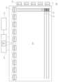
도 1을 참조하면, 본 실시예들에 따른 유기발광표시장치(100)는, 다수의 데이터라인(DL1~DLm) 및 다수의 게이트라인(GL1~GLn)이 배치되고, 다수의 서브픽셀(SP: Sub Pixel)이 배치된 표시패널(110)과, 표시패널(110)의 상단 또는 하단에 연결되고 다수의 데이터라인(DL1~DLm)을 구동하는 소스 드라이버(120)와, 다수의 게이트라인(GL1~GLn)을 구동하는 게이트 드라이버(130)와, 소스 드라이버(120) 및 게이트 드라이버(130)를 제어하는 타이밍 컨트롤러(140)와, 인체를 감지한 결과를 타이밍 컨트롤러(140)로 제공하는 인체감지부(170) 등을 포함한다.Referring to FIG. 1, the organic light
도 1을 참조하면, 표시패널(110)에는 다수의 서브픽셀(SP)이 매트릭스 타입으로 배치된다.Referring to FIG. 1, a plurality of subpixels (SP) are arranged in a matrix type on the
소스 드라이버(120)는, 다수의 데이터라인(DL1~DLm)으로 데이터전압을 공급함으로써, 다수의 데이터라인(DL1~DLm)을 구동한다.The
게이트 드라이버(130)는, 타이밍 컨트롤러(140)의 제어에 따라, 온(On) 전압 또는 오프(Off) 전압의 스캔 신호를 다수의 게이트라인(GL1~GLn)으로 순차적으로 공급하여 다수의 게이트라인(GL1~GLn)을 순차적으로 구동한다. 여기서, 게이트 드라이버(130)는 스캔 드라이버라고도 한다.The
게이트 드라이버(130)는, 구동 방식이나 패널 설계 방식 등에 따라서, 도 1에서와 같이, 표시패널(110)의 일 측에만 위치할 수도 있고, 경우에 따라서는, 양측에 위치할 수도 있다. 또한, 게이트 드라이버(130)는, 하나 이상의 게이트 드라이버 집적회로(GDIC: Gate Driver Integrated Circuit)를 포함할 수 있다.The
소스 드라이버(120)는, 특정 게이트라인이 열리면, 타이밍 컨트롤러(140)로부터 수신한 영상 데이터(Data)를 아날로그 형태의 데이터전압(Vdata)으로 변환하여 다수의 데이터라인(DL1~DLm)으로 공급함으로써, 다수의 데이터라인(DL1~DLm)을 구동한다.When a specific gate line is opened, the
소스 드라이버(120)는, 적어도 하나의 소스 드라이버 집적회로(SDIC: Source Driver Integrated Circuit)를 포함하여 다수의 데이터라인을 구동할 수 있다.The
각 전술한 게이트 드라이버 집적회로 또는 소스 드라이버 집적회로는, 테이프 오토메티드 본딩(TAB: Tape Automated Bonding) 방식 또는 칩 온 글래스(COG) 방식으로 표시패널(110)의 본딩 패드(Bonding Pad)에 연결되거나, 표시패널(110)에 직접 배치될 수도 있으며, 경우에 따라서, 표시패널(110)에 집적화되어 배치될 수도 있다.Each of the above-described gate driver integrated circuits or source driver integrated circuits is connected to the bonding pad of the
각 소스 드라이버 집적회로는, 쉬프트 레지스터, 래치 회로 등을 포함하는 로직부와, 디지털 아날로그 컨버터(DAC: Digital Analog Converter)와, 출력 버퍼와, 아날로그 디지털 컨버터(310)(ADC: Analog Digital Converter) 등을 포함할 수 있다.Each source driver integrated circuit includes a logic unit including a shift register, a latch circuit, etc., a digital analog converter (DAC: Digital Analog Converter), an output buffer, an analog-to-digital converter (310) (ADC: Analog Digital Converter), etc. may include.
여기서, 아날로그 디지털 컨버터(310)는 복수의 서브픽셀과 센싱라인을 통해 연결되어 있으며, 각 서브픽셀의 구동 트랜지스터의 임계전압을 감지할 수 있다.Here, the analog-to-
한편, 본 실시예들에 따른 유기발광표시장치(Organic Light Emitting Display Device)는, 각 서브픽셀(SP)이 유기발광다이오드(OLED: Organic Light Emitting Diode)와, 이를 구동하기 위한 트랜지스터(DRT: Driving Transistor) 등의 회로 소자로 구성되어 있다. 각 서브픽셀(SP)을 구성하는 회로 소자의 종류 및 개수는, 제공 기능 및 설계 방식 등에 따라 다양하게 정해질 수 있다.Meanwhile, in the organic light emitting display device according to the present embodiments, each subpixel (SP) includes an organic light emitting diode (OLED) and a transistor (DRT: driving driving device) for driving the organic light emitting diode (OLED). It is composed of circuit elements such as transistors. The type and number of circuit elements constituting each subpixel (SP) may be determined in various ways depending on the provided function and design method.
도 2는 본 실시예들에 따른 유기발광표시장치의 서브픽셀 회로를 나타낸 도면이다.Figure 2 is a diagram showing a subpixel circuit of an organic light emitting display device according to the present embodiments.
도 2의 서브픽셀은 i번째 데이터라인(DLi, 1=i≤=m)으로부터 데이터전압(Vdata)을 공급받는 임의의 서브픽셀이다.The subpixel in FIG. 2 is an arbitrary subpixel that receives the data voltage (Vdata) from the i-th data line (DLi, 1=i≤=m).
도 2를 참조하면, 서브픽셀 회로는 구동 트랜지스터(DRT), 스위칭 트랜지스터(SWT: Switching Transistor), 센싱 트랜지스터(SENT: Sensing Transistor), 스토리지 캐패시터(Cst: Storage Capacitor)를 포함할 수 있다.Referring to FIG. 2, the subpixel circuit may include a driving transistor (DRT), a switching transistor (SWT), a sensing transistor (SENT), and a storage capacitor (Cst).
구동 트랜지스터(DRT)는 유기발광다이오드(OLED)로 구동 전류를 공급해줌으로써 유기발광다이오드(OLED)를 구동하며, 구동 트랜지스터(DRT)는 유기발광다이오드(OLED)와 구동전압(EVDD)을 공급하는 구동전압 라인(DVL) 사이에 연결될 수 있다. 구동 트랜지스터(DRT)는 소스 노드 또는 드레인 노드에 해당하는 제1노드(N1), 게이트 노드에 해당하는 제2노드(N2), 드레인 노드 또는 소스 노드에 해당하는 제3노드(N3)를 갖는다.The driving transistor (DRT) drives the organic light-emitting diode (OLED) by supplying driving current to the organic light-emitting diode (OLED), and the driving transistor (DRT) supplies driving voltage (EVDD) to the organic light-emitting diode (OLED). It can be connected between voltage lines (DVL). The driving transistor DRT has a first node N1 corresponding to the source node or the drain node, a second node N2 corresponding to the gate node, and a third node N3 corresponding to the drain node or source node.
스위칭 트랜지스터(SWT)는 데이터라인(DLi)과 구동 트랜지스터(DRT)의 제2노드(N2) 사이에 연결되고, 게이트 노드로 스캔 신호(SCAN)를 인가받아 턴온된다. 스위칭 트랜지스터(SWT)는 스캔 신호(SCAN)에 의해 턴온되어 데이터라인(DLi)으로부터 공급된 데이터전압(Vdata)을 구동 트랜지스터(DRT)의 제2노드(N2)로 전달해준다.The switching transistor (SWT) is connected between the data line (DLi) and the second node (N2) of the driving transistor (DRT), and is turned on by receiving a scan signal (SCAN) to the gate node. The switching transistor (SWT) is turned on by the scan signal (SCAN) and transfers the data voltage (Vdata) supplied from the data line (DLi) to the second node (N2) of the driving transistor (DRT).
센싱 트랜지스터(SENT)는 구동 트랜지스터(DRT)의 제1노드(N1)와 기준전압(VREF)을 공급하는 기준전압 라인(RVL) 사이에 연결되고, 게이트 노드로 스캔 신호의 일종인 센싱 신호(SENSE)를 인가받아 턴온된다. 센싱 트랜지스터(SENT)는 센싱 신호(SENSE)에 의해 턴온되어 기준전압 라인(RVL)을 통해 공급되는 기준전압(VREF)을 구동 트랜지스터(DRT)의 제1노드(N1)에 인가해준다. 또한, 센싱 트랜지스터(SENT)는 센싱 구성이 구동 트랜지스터(DRT)의 제1노드(N1)의 전압을 센싱할 수 있도록 센싱 경로로서의 역할도 해줄 수 있다.The sensing transistor (SENT) is connected between the first node (N1) of the driving transistor (DRT) and the reference voltage line (RVL) that supplies the reference voltage (VREF), and the sensing signal (SENSE), a type of scan signal, is connected to the gate node. ) is authorized and turns on. The sensing transistor (SENT) is turned on by the sensing signal (SENSE) and applies the reference voltage (VREF) supplied through the reference voltage line (RVL) to the first node (N1) of the driving transistor (DRT). Additionally, the sensing transistor (SENT) can also serve as a sensing path so that the sensing configuration can sense the voltage of the first node (N1) of the driving transistor (DRT).
한편, 스캔 신호(SCAN) 및 센싱 신호(SENSE)는 다른 게이트라인을 통해 스위칭 트랜지스터(SWT)의 게이트 노드 및 센싱 트랜지스터(SENT)의 게이트 노드로 각각 인가될 수도 있다. 경우에 따라서는, 스캔 신호(SCAN) 및 센싱 신호(SENSE)는 동일한 신호로서, 동일한 게이트라인을 통해 스위칭 트랜지스터(SWT)의 게이트 노드 및 센싱 트랜지스터(SENT)의 게이트 노드로 각각 인가될 수도 있다.Meanwhile, the scan signal SCAN and the sensing signal SENSE may be applied to the gate node of the switching transistor SWT and the gate node of the sensing transistor SENT, respectively, through other gate lines. In some cases, the scan signal SCAN and the sensing signal SENSE are the same signal and may be applied to the gate node of the switching transistor SWT and the gate node of the sensing transistor SENT, respectively, through the same gate line.
본 실시예들에 따른 유기발광표시장치(100)는, 센싱 구동을 제어하기 위하여, 즉, 서브픽셀(SP) 내 구동 트랜지스터(DRT)의 제1노드(N1)의 전압 인가 상태를 제어하기 위하여, 샘플링 스위치(SW)를 포함할 수 있다. 이 샘플링 스위치(SW)를 통해, 기준전압 라인(RVL)의 일단(Nc)은 기준전압 공급노드(Na) 또는 아날로그 디지털 컨버터(310)의 노드(Nb)와 연결될 수 있다.The organic light emitting
기준전압 라인(RVL)은, 기본적으로는, 기준전압(VREF)을 센싱 트랜지스터(SENT)를 통해 구동 트랜지스터(DRT)의 제1노드(N1)로 공급해주는 라인이다. 한편, 기준전압 라인(RVL)에는 라인 캐패시터(Cline)가 형성되는데, 아날로그 디지털 컨버터(310)는 필요한 시점에 기준전압 라인(RVL) 상의 라인 캐패시터(Cline)에 충전된 전압을 센싱한다. 따라서, 아래에서는, 기준전압 라인(RVL)을 센싱라인이라고도 기재한다.The reference voltage line (RVL) is basically a line that supplies the reference voltage (VREF) to the first node (N1) of the driving transistor (DRT) through the sensing transistor (SENT). Meanwhile, a line capacitor Cline is formed on the reference voltage line RVL, and the analog-to-
이러한 기준전압 라인(RVL)은, 일 예로, 서브픽셀 열마다 1개씩 배치될 수도 있고, 둘 이상의 서브픽셀 열마다 1개씩 배치될 수도 있다.For example, one such reference voltage line RVL may be arranged for each subpixel column, or one for each subpixel column of two or more subpixels.
예를 들어, 1개의 픽셀이 4개의 서브픽셀(적색 서브픽셀, 흰색 서브픽셀, 녹색 서브픽셀, 청색 서브픽셀)로 구성된 경우, 1개의 픽셀 열마다 1개씩 배치될 수도 있다.For example, if one pixel consists of four subpixels (red subpixel, white subpixel, green subpixel, and blue subpixel), one pixel may be placed in each pixel column.
소스 드라이버 집적회로의 아날로그 디지털 컨버터(310)는 다수 서브픽셀(SP) 라인 중에서 센싱 구동이 이루어지는 서브픽셀(SP)의 구동 트랜지스터(DRT)의 제1노드(N1)의 전압을 감지하며, 제1노드(N1)의 전압은 제1노드(N1)에 전기적으로 연결된 센싱라인(RVL)의 전압을 감지하여 알아낼 수 있다. 이때, 아날로그 디지털 컨버터(310)는, 센싱라인(RVL)으로 흐르는 전류를 이용하여 센싱라인(RVL) 상의 라인 캐패시터(Cline)에 충전된 전압을 센싱하게 되며, 여기서, 라인 캐패시터(Cline)에 충전된 전압은 센싱라인(RVL)의 전압이고, 이 전압은 구동 트랜지스터(DRT)의 제1노드(N1)의 전압과 동일하다.The analog-to-
센싱 구동시, 구동 트랜지스터(DRT)의 제1노드(N1)의 전압이 라인 캐패시터(Cline)에 저장되고, 아날로그 디지털 컨버터(310)는 구동 트랜지스터(DRT)의 제1노드(N1)의 전압을 직접 센싱하는 것이 아니라, 구동 트랜지스터(DRT)의 제1노드(N1)의 전압이 저장되는 라인 캐패시터(Cline)의 충전 전압을 센싱하기 때문에, 센싱 트랜지스터(SENT)의 턴오프 시에도, 구동 트랜지스터(DRT)의 제1노드(N1)의 전압을 센싱할 수 있다.During sensing operation, the voltage of the first node (N1) of the driving transistor (DRT) is stored in the line capacitor (Cline), and the analog-to-
이러한 서브픽셀(SP)의 구동 트랜지스터(DRT)의 임계전압(Vth)을 산출하기 위해서는 먼저 아날로그 디지털 컨버터(310)에서 각 구동 트랜지스터(DRT)의 제1노드(N1)의 전압을 센싱해야 한다.In order to calculate the threshold voltage (Vth) of the driving transistor (DRT) of the subpixel (SP), the analog-to-
아날로그 디지털 컨버터(310)는 타이밍 컨트롤러의 전압보상부(145)로부터의 제어에 따라, 라인 캐패시터(Cline)에 충전된 전압을 센싱하여 제1노드의 전압을 센싱한다. 이를 위해, 전압보상부(145)는 샘플링 스위치(SW)를 기준전압(Vref) 측으로 스위칭하여 각 서브픽셀(SP)에 기준전압이 인가되도록 한 다음, 다시 샘플링 스위치(SW)를 아날로그 디지털 컨버터(310)로 스위칭하여, 아날로그 디지털 컨버터(310)에서 제1노드(N1)의 전압을 측정하도록 한다. 그런 다음, 아날로그 디지털 컨버터(310)에서 센싱된 제1노드(N1)의 전압은 전압보상부(145)로 제공되고, 전압보상부(145)에서는 각 구동 트랜지스터(DRT)의 임계전압(Vth)을 산출한다. 산출된 임계전압(Vth)은 타이밍 컨트롤러의 메모리(147)에 저장되고, 타이밍 컨트롤러(140)에서는 각 서브픽셀(SP)에 제공될 데이터전압(Vdata)이 임계전압(Vth)의 차이가 보상되도록 영상 데이터를 조절하여 소스 드라이버로 전달한다. 이에 따라, 표시패널(110)의 모든 서브픽셀의 휘도가 설정된 상태로 표시되기 때문에 선명하고 균일한 화질의 영상이 표시될 수 있다.The analog-to-
한편, 타이밍 컨트롤러(140)는, 소스 드라이버(120) 및 게이트 드라이버(130)로 각종 제어신호를 공급하여, 소스 드라이버(120) 및 게이트 드라이버(130)를 제어한다.Meanwhile, the
타이밍 컨트롤러(140)는, 각 프레임에서 구현하는 타이밍에 따라 스캔을 시작하고, 외부에서 입력되는 입력 영상 데이터를 소스 드라이버(120)에서 사용하는 데이터 신호 형식에 맞게 전환하여 전환된 영상 데이터(Data)를 출력하고, 스캔에 맞춰 적당한 시간에 데이터 구동을 통제한다.The
타이밍 컨트롤러(140)는, 외부로부터 입력된 입력 영상 데이터를 소스 드라이버(120)에서 사용하는 데이터 신호 형식에 맞게 전환하여 전환된 영상 데이터(Data)를 출력하는 것 이외에, 소스 드라이버(120) 및 게이트 드라이버(130)를 제어하기 위하여, 수직 동기 신호(Vsync), 수평 동기 신호(Hsync), 입력 DE 신호, 클럭 신호 등의 타이밍 신호를 입력받아, 각종 제어 신호들을 생성하여 소스 드라이버(120) 및 게이트 드라이버(130)로 출력한다.The
예를 들어, 타이밍 컨트롤러(140)는, 게이트 드라이버(130)를 제어하기 위하여, 게이트 스타트 펄스(GSP: Gate Start Pulse), 게이트 쉬프트 클럭(GSC: Gate Shift Clock), 게이트 출력 인에이블 신호(GOE: Gate Output Enable) 등을 포함하는 각종 게이트 제어 신호(GCS: Gate Control Signal)를 출력한다.For example, the
여기서, 게이트 스타트 펄스(GSP)는 게이트 드라이버(130)를 구성하는 하나 이상의 게이트 드라이버 집적회로의 동작 스타트 타이밍을 제어한다. 게이트 쉬프트 클럭(GSC)은 하나 이상의 게이트 드라이버 집적회로에 공통으로 입력되는 클럭 신호로서, 스캔 신호(게이트 펄스)의 쉬프트 타이밍을 제어한다. 게이트 출력 인에이블 신호(GOE)는 하나 이상의 게이트 드라이버 집적회로의 타이밍 정보를 지정하고 있다.Here, the gate start pulse (GSP) controls the operation start timing of one or more gate driver integrated circuits constituting the
또한, 타이밍 컨트롤러(140)는, 소스 드라이버(120)를 제어하기 위하여, 소스 스타트 펄스(SSP: Source Start Pulse), 소스 샘플링 클럭(SSC: Source Sampling Clock), 소스 출력 인에이블 신호(SOE: Souce Output Enable) 등을 포함하는 각종 데이터 제어 신호(DCS: Data Control Signal)를 출력한다.Additionally, the
여기서, 소스 스타트 펄스(SSP)는 소스 드라이버(120)를 구성하는 하나 이상의 소스 드라이버 집적회로의 데이터 샘플링 시작 타이밍을 제어한다. 소스 샘플링 클럭(SSC)은 소스 드라이버 집적회로 각각에서 데이터의 샘플링 타이밍을 제어하는 클럭 신호이다. 소스 출력 인에이블 신호(SOE)는 소스 드라이버(120)의 출력 타이밍을 제어한다.Here, the source start pulse (SSP) controls the data sampling start timing of one or more source driver integrated circuits constituting the
한편, 본 실시예에 따른 타이밍 컨트롤러(140)는 컨트롤 인쇄회로기판(160) 상에 배치되며, 도 3에 도시된 바와 같이, 인체감지부(170)에서 감지된 결과를 이용하여 인체의 위치를 판단하는 인체판단부(141)와, 각 서브픽셀(SP)의 구동 트랜지스터(DRT)의 임계전압에 따른 보상을 결정하는 전압보상부(145)와, 소스 드라이버로 제공되는 영상 데이터의 휘도값을 조절하는 휘도조절부(143)와, 각 구동 트랜지스터(DRT)의 임계전압을 저장하는 메모리(147)를 포함할 수 있다.Meanwhile, the
인체감지부(170)는, 유기발광표시장치(100)의 전방에 인체가 존재하는지 여부와 인체가 어느 위치에 존재하는지를 감지하기 위한 것으로서, 인체를 감지하기 위한 다양한 수단으로 구성될 수 있다. 예를 들어, 인체감지부(170)로는 초음파를 이용한 초음파센서, 인체의 이미지를 촬영하는 카메라 등을 적용할 수 있으며, 인체감지부(170)는 이에 한정되지 아니하고 인체를 감지할 수 있는 여하한 장치로 구성될 수 있다.The human
인체감지부(170)에서 감지된 정보는 타이밍 컨트롤러의 인체판단부(141)로 전달될 수 있다.Information detected by the human
인체판단부(141)에서는 인체감지부(170)에서 감지된 정보에 따라, 인체의 존재 여부와 표시패널(110)에 대한 인체의 위치를 판단하게 된다. 인체판단부(141)에서는 유기발광표시장치(100)에 대한 인체의 위치를 각도로 산출할 수 있다. 이때 유기발광표시장치(100)의 중심을 0도로 설정하고, 유기발광표시장치(100)의 우측과 좌측을 각각 90도로 하여 인체의 위치를 좌측 90도 내지 우측 90도 사이에서 산출할 수도 있고, 도 4에 도시된 바와 같이, 유기발광표시장치(100)의 우측 또는 좌측을 0도로 하고, 좌측 또는 우측을 180로 하여 인체의 위치를 산출할 수도 있다.The human
인체판단부(141)에서 판단된 인체의 존재 여부와 위치에 대한 정보는 각각 전압보상부(145)와 휘도조절부(143)로 제공될 수 있다.Information on the existence and location of the human body determined by the human
전압보상부(145)에서는 인체판단부(141)로부터 제공된 인체의 존재 여부에 따라, 아날로그 디지털 컨버터(310)에서 감지된 제1노드(N1)의 전압과 데이터전압(Vdata)을 이용하여 각 서브픽셀(SP)의 구동 트랜지스터(DRT)의 임계전압(Vth)을 산출하고, 산출된 임계전압(Vth)을 메모리(147)에 저장한다.The
타이밍 컨트롤러(140)에서는 메모리(147)에 저장된 임계전압을 이용하여 각 서브픽셀(SP)에 제공되는 데이터전압(Vdata)이 조절되도록 조절된 휘도가 포함된 영상 데이터를 소스 드라이버로 제공할 수 있다.The
한편, 전압보상부(145)는, 인체판단부(141)에서 제공된 정보에 따라 인체가 존재하지 않는다고 판단되면, 미리 설정된 소정 시간을 대기하고, 소정 시간이 경과하면, 전압보상을 위한 각 서브픽셀(SP)의 구동 트랜지스터(DRT)의 임계전압(Vth)을 산출하는 산출과정을 개시하도록 한다.Meanwhile, if the
먼저, 전압보상부(145)는 DC 전원을 오프시켜 표시패널(110)에 제공되는 전원을 차단하고, 센싱라인에 설치된 샘플링 스위치(SW)가 기준전압과 연결되도록 한 다음, 일정 시간이 경과하면 샘플링 스위치(SW)가 아날로그 디지털 컨버터(310)에 연결되도록 함으로써, 각 구동 트랜지스터(DRT)의 전압을 센싱하도록 한다. 그런 다음, 전압보상부(145)는 데이터전압(Vdata)과 각 구동 트랜지스터(DRT) 전압 간의 차이를 산출하여 임계전압(Vth)을 산출하게 된다.First, the
또한, 전압보상부(145)는 산출된 구동 트랜지스터(DRT)의 임계전압(Vth)을 메모리(147)에 저장하고, 차후에 유기발광표시장치(100)의 DC 전원이 온되면, 해당 임계전압(Vth)에 따라 각 서브픽셀(SP)에 제공되는 데이터전압(Vdata)이 조절되도록 한다. 이에 따라, 각 서브픽셀(SP)의 임계전압(Vth)의 차이에 따라 발생하는 색상 및 휘도의 차이를 보상할 수 있다. 뿐만 아니라, 유기발광표시장치(100)의 구동중, 시청자가 자리를 비운 사이에 각 구동 트랜지스터(DRT)의 임계전압(Vth)을 산출하여 신속하게 보상할 수 있도록 함으로써, 보다 고품질의 영상을 제공할 수 있다.In addition, the
휘도조절부(143)는 인체감지부(170)로부터 감지된 결과에 따라, 인체가 존재하는 경우, 인체의 위치에 따라 휘도를 조절할 수 있다. 휘도조절부(143)는 인체가 존재하는 경우 인체가 표시패널(110)의 정면에 위치하는지, 표시패널(110)의 정면으로부터 일정 각도 벗어난 위치, 즉 시야각이 큰 위치에 존재하는지에 따라 휘도를 조절할 수 있다. 즉, 휘도조절부(143)는 인체가 표시패널(110)의 정면으로부터 미리 설정된 일정 시야각 내에 위치하면, 휘도의 조절이 필요없다고 판단할 수 있다. 그러나 휘도조절부(143)는 인체가 표시패널(110)의 정면으로부터 일정 시야각 외부에 존재하는 경우, 표시패널(110)의 휘도를 상승시킬 수 있다.If a human body exists, the
예를 들어, 휘도조절부(143)는, 도 4에 도시된 바와 같이, 인체가 표시패널(110)의 A에서 A' 사이에 위치하고 있는 경우, 즉, 인체가 표시패널(110)의 중심을 기준으로 좌우 각각 일정 시야각 이내에 위치하는 경우에는 휘도를 조절하지 아니하고 정상 휘도로 출력되도록 한다.For example, as shown in FIG. 4, the
반면, 휘도조절부(143)는 인체가 표시패널(110)의 A에서 B 사이, A'에서 B' 사이에 위치하는 경우, 즉, 인체가 표시패널(110)의 중심을 기준으로 일정 시야각 외부에 존재하는 경우에는 휘도를 상승시킴으로써, 표시패널(110)에 표시되는 영상이 밝아지도록 한다. 이에 따라, 시청자가 표시패널(110)의 정면을 기준으로 일정 시야각 외부에 위치하는 경우에도 충분히 밝은 영상을 시청할 수 있다.On the other hand, the
한편, 휘도조절부(143)는 인체감지부(170)에서 인체를 감지하지 못하고 소정 시간이 경과한 경우, 인체를 감지할 때까지 휘도를 일정 레벨로 순간적으로 감지시키거나 점차적으로 감소시킬 수 있다. 즉, 시청자가 표시패널(110)을 시청하고 있지 아니한 경우에는 휘도를 감소시킴으로써, 불필요하게 전력이 낭비되는 것을 방지할 수 있다. 이에 따라, 이렇게 휘도조절부(143)가 휘도를 감소시키는 모드를 전력절약모드라 한다.Meanwhile, when a predetermined time has elapsed without the human
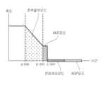
예를 들어, 도 5에 도시된 바와 같이, 휘도조절부(143)는, 인체감지부(170)로부터 감지결과에 따라, 인체가 감지되지 아니한 시간이 a분이 경과하면, 전력절약모드로 돌입하여 휘도를 감소시킬 수 있다. 이때, 휘도조절부(143)는, 전력절양모드에서 휘도를 미리 설정된 레벨로 급격히 감소시킬 수도 있고, 도 5에 도시된 바와 같이, 일정 기울기를 가지고 서서히 감소시킬 수도 있다.For example, as shown in FIG. 5, the
이렇게 휘도조절부(143)에서 전력절약모드에 돌입하여 휘도를 감소시킬 경우, 표시패널(110) 전체에 대해 정상 휘도를 일정 비율로 감소시키게 된다. 즉, 휘도가 254인 경우와 휘도가 10인 경우, 동일한 비율, 예를 들어 50%의 비율로 휘도를 감소시키게 되면, 휘도가 254인 경우에는 127로 감소되고, 휘도가 10인 경우에는 5로 감소된다.When the
또한, 휘도조절부(143)는, 전략절약모드에 돌입한 이후, 인체가 감지되지 않은 시간이 미리 설정된 시간을 경과하면, 휘도를 0 또는 0에 가까운 상태로 출력함으로써, 표시패널(110)이 블랙으로 또는 어둡게 표시되도록 한다. 이때, 전압보상부(145)가 작동하여 각 서브픽셀(SP)의 구동 트랜지스터(DRT)의 임계전압(Vth)이 산출 및 보상되도록 한다. 이 모드를 전압센싱모드라 한다. 이러한 전압센싱모드에서 표시패널(110)을 어둡게 함으로써, 각 구동 트랜지스터(DRT)의 센싱시 발생하는 라인이 표시패널(110)에 표시되지 않도록 할 수 있다.In addition, the
한편, 휘도조절부(143)는 전력절약모드와 전압센싱모드 사이에 일정 버퍼모드를 둘 수 있다. 즉, 도 5에 도시된 바와 같이, 전력절약모드가 b-a분으로 설정되어 있는 경우, b-a분이 경과한 이후 바로 전압센싱모드로 돌입하는 것이 아니라, c-b분 정도의 버퍼모드를 두어 전압센싱모드로 돌입하는 것을 지연시킬 수 있다.Meanwhile, the
전력절약모드에서 휘도를 서서히 감소시키는 경우, 버퍼모드에서는 더이상 휘도를 감소시키지 아니하고, 전력절약모드의 마지막 휘도를 버퍼모드에서는 유지시킬 수 있다.When the luminance is gradually reduced in the power saving mode, the luminance is no longer reduced in the buffer mode, and the last luminance in the power saving mode can be maintained in the buffer mode.
전압센싱모드가 완료되고, 여전히 인체가 감지되지 아니하면, 휘도조절부(143)는 표시패널(110)을 내부 패턴으로 동작시키는 AGP(Auto Generation Pattern) 모드에 돌입하도록 한다. 이때, 유기발광표시장치(100)의 내부 패턴은 블랙이므로, 휘도조절부(143)는 표시패널(110)이 블랙으로 표시되도록 한다. 이러한 AGP 모드에 의해 전력소비를 감소시킬 수 있다.When the voltage sensing mode is completed and the human body is still not detected, the
이러한 타이밍 컨트롤러(140)는, 적어도 하나의 소스 드라이버 집적회로가 본딩된 소스 인쇄회로기판과 연성 플랫 케이블(FFC: Flexible Flat Cable) 또는 연성 인쇄 회로(FPC: Flexible Printed Circuit) 등의 연결 매체를 통해 연결된 컨트롤 인쇄회로기판(Control Printed Circuit Board)에 배치될 수 있다.This
이러한 구성에 의한 유기발광표시장치(100)에서 인체감지를 통해 휘도 조절, 구동 트랜지스터(DRT)의 임계전압(Vth) 보상, AGP 기능을 구현하는 과정을 도 6을 참조하여 설명하면 다음과 같다.The process of implementing the brightness control, threshold voltage (Vth) compensation of the driving transistor (DRT), and AGP function through human body detection in the organic light emitting
도 6에 도시된 바와 같이, 유기발광표시장치(100)에 AC 전원과 DC 전원이 제공되어 턴온되면(S600), 인체감지부(170)에서는 인체를 감지하고(S605), 감지 결과를 타이밍 컨트롤러(140)로 제공할 수 있다. 타이밍 컨트롤러(140)의 인체판단부(141)에서는 인체의 존재 여부와, 인체의 위치를 판단하여 휘도조절부(143)로 전달하게 된다(S610).As shown in FIG. 6, when AC power and DC power are provided to the organic light emitting
인체판단부(141)에서 인체가 존재한다고 판단하고, 인체가 표시패널(110)의 중심을 기준으로 미리 설정된 소정 시야각 내에 위치하는지 판단하면(S615-Y), 휘도조절부(143)는 정상 휘도의 출력을 결정한다(S620). 반면, 인체가 표시패널(110)의 중심을 기준으로 소정 범위안에 위치하지 않는 경우(S615-N), 휘도조절부(143)에서는 휘도를 정상 휘도보다 일정 비율 높여서 출력하도록 결정한다(S625). 휘도조절부(143)에서 결정된 휘도에 따라, 타이밍 컨트롤러(140)에서 데이터전압(Vdata)을 조절하여 소스 드라이버로 제공하게 된다. 이에 따라, 시청자가 표시패널(110)의 중심에 대해 일정 범위 벗어난 측면에서 시청할 경우에도 충분히 밝은 영상을 볼 수 있게 된다.When the human
이러한 과정은 유기발광표시장치(100)가 턴오프될 때까지 반복된다(S630).This process is repeated until the organic light emitting
한편, S610에서 인체판단부(141)에서 인체가 존재하지 않는다고 판단하면(S610-N), 휘도조절부(143)는 인체가 존재하지 아니한 시간이 미리 설정된 일정 시간을 경과하였는지 확인한다(S635). 그런 다음, 휘도조절부(143)에서는 표시패널(110)의 휘도를 저하시켜 전력절약모드에 돌입할 수 있다(S640). 이때, 휘도조절부(143)는 휘도를 일정 레벨로 순간적으로 저하시킬 수도 있고, 해당 레벨까지 일정 기울기를 가지고 서서히 감소시킬 수도 있다.Meanwhile, if the human
휘도조절부(143)는 전력절약모드 중 지속적으로 인체판단부(141)로부터 인체의 존재여부에 대한 정보를 제공받게 되며, 인체가 존재하지 않는 상태에서(S645), 전력절약모드에 돌입한 이후 일정 시간이 경과하면(S650), 버퍼모드에 돌입하여 더이상 휘도를 감소시키지 않고 일정 시간동안 유지시키게 된다(S655).The
그런 다음, 버퍼모드 동안에도 인체가 감지되지 아니하고 일정 시간이 경과하면(S660), 휘도조절부(143)는 휘도를 급격히 저하시켜 블랙 화면을 제공한다.Then, when a certain period of time elapses without the human body being detected even during the buffer mode (S660), the
전압보상부(145)에서는 인체감지부(170)에서 인체의 존재여부가 감지되지 않는다고 감지되면, 휘도조절부(143)에서의 전력절약모드과 버퍼모드를 합한 시간만큼 대기한 다음, 전압센싱모드를 시작할 수 있다(S665).When the
전압센싱모드가 시작되면, 전압보상부(145)에서는 샘플링 스위치(SW)를 기준전압 공급노드(Na)에 연결시켜 기준전압을 공급받고, 일정 시간이 경과하면 샘플링 스위치(SW)를 아날로그 디지털 컨버터(310)측 노드(Nb)에 연결시켜 센싱이 이루어지도록 한다.When the voltage sensing mode starts, the
그러면 아날로그 디지털 컨버터(310)에서는 제1노드(N1)의 전압을 감지하여 전압보상부(145)로 전달한다. 전압보상부(145)에서는 타이밍 컨트롤러(140)로부터 데이터전압(Vdata)에 대한 정보를 제공받고, 데이터전압(Vdata)에서 제1노드의 전압을 뺀 임계전압(Vth)를 산출한다. 전압보상부(145)는 산출된 임계전압(Vth)을 메모리(147)에 저장하고, 임계전압에 따라 각 서브픽셀(SP)에 제공되는 보상전압값을 산출할 수 있다. 이렇게 산출된 보상전압값은 인체판단부(141)에서 인체가 감지되었다고 판단하고, 표시패널(110)에 정상 휘도가 제공될 때, 타이밍 컨트롤러(140)는 각 서브픽셀(SP)에 제공되는 데이터전압(Vdata)을 조절하게 된다.Then, the analog-to-
이러한 전압보상 공정중에도 휘도조절부(143)는 인체판단부(141)에서 판단된 인체 존재 여부에 대한 정보를 제공받으며, 휘도조절부(143)는 전압보상공정이 완료되었는데도 인체가 감지되지 않으면(S670,S675-N), AGP 모드에 돌입한다(S680). 휘도조절부(143)는 표시패널(110)이 블랙으로 표시되도록 휘도를 0으로 조절하여 출력되도록 한다. AGP 모드는 인체판단부(141)에서 인체가 감지되었다고 판단될 때까지 지속될 수 있다(S685). 이러한 과정 중 언제든지 인체가 감지되면, 휘도조절부(143)는 휘도를 정상 휘도로 복원하여 영상이 표시되도록 한다(S690).Even during this voltage compensation process, the
이와 같이, 본 실시예에서는 인체를 감지하여 시청자가 유기발광표시장치(100)의 측면에 가까이 위치하는 경우에는 휘도를 상승시켜 시청자가 충분한 밝기를 가진 영상을 시청할 수 있도록 함으로써, 시청자의 만족도를 향상시킬 수 있다. 또한, 본 발명에서는 인체가 감지되지 않으면, 휘도를 서서히 감소시키거나 블랙으로 전환시켜 에너지를 절약할 수 있도록 한다. 뿐만 아니라, 인체가 감지되지 않는 동안, 각 서브픽셀(SP)의 구동 트랜지스터(DRT)의 임계전압(Vth)을 감지하여 보상할 수 있도록 함으로써, AC 전원이 오프되거나 유기발광표시장치(100)의 구동 시간이 일정 이하인 경우에도 임계전압을 감지할 수 있게 되어 임계전압(Vth)의 차이를 보상할 수 있게 된다.As such, in this embodiment, when the human body is detected and the viewer is located close to the side of the organic light emitting
상술한 실시예에 설명된 특징, 구조, 효과 등은 본 발명의 적어도 하나의 실시예에 포함되며, 반드시 하나의 실시예에만 한정되는 것은 아니다. 나아가, 각 실시예에서 예시된 특징, 구조, 효과 등은 실시예들이 속하는 분야의 통상의 지식을 가지는 자에 의하여 다른 실시예들에 대해서도 조합 또는 변형되어 실시 가능하다. 따라서 이러한 조합과 변형에 관계된 내용들은 본 발명의 범위에 포함되는 것으로 해석되어야 할 것이다.The features, structures, effects, etc. described in the above-described embodiments are included in at least one embodiment of the present invention and are not necessarily limited to only one embodiment. Furthermore, the features, structures, effects, etc. illustrated in each embodiment can be combined or modified and implemented in other embodiments by a person with ordinary knowledge in the field to which the embodiments belong. Therefore, contents related to such combinations and modifications should be construed as being included in the scope of the present invention.
또한, 이상에서 실시예들을 중심으로 설명하였으나 이는 단지 예시일 뿐 본 발명을 한정하는 것이 아니며, 본 발명이 속하는 분야의 통상의 지식을 가진 자라면 본 실시예의 본질적인 특성을 벗어나지 않는 범위에서 이상에 예시되지 않은 여러 가지의 변형과 응용이 가능함을 알 수 있을 것이다. 예를 들어, 실시예들에 구체적으로 나타난 각 구성 요소는 변형하여 실시할 수 있는 것이다. 그리고 이러한 변형과 응용에 관계된 차이점들은 첨부한 청구 범위에서 규정하는 본 발명의 범위에 포함되는 것으로 해석되어야 할 것이다.In addition, although the description has been made focusing on the embodiments above, this is only an example and does not limit the present invention, and those skilled in the art will understand the above examples without departing from the essential characteristics of the present embodiments. You will be able to see that various modifications and applications are possible. For example, each component specifically shown in the embodiments can be modified and implemented. And these variations and differences in application should be construed as being included in the scope of the present invention as defined in the attached claims.
100 : 유기발광표시장치
110 : 표시패널
140 : 타이밍 컨트롤러
141 : 인체판단부
143 : 휘도조절부
145 : 전압보상부
170 : 인체감지부100: Organic light emitting display device
110: display panel
140: timing controller
141: Human body judgment unit
143: Brightness control unit
145: Voltage compensation unit
170: Human body detection unit
Claims (12)
Translated fromKorean상기 표시패널의 전방에 존재하는 인체를 감지하는 인체감지부;
상기 인체감지부로부터의 감지 정보에 따라 상기 인체의 존재 여부와 상기 인체의 상기 표시패널에 대한 위치를 판단하는 인체판단부;
상기 인체판단부로부터의 판단결과에 따라, 상기 표시패널의 휘도의 조절여부를 결정하는 휘도조절부; 및
상기 휘도조절부로부터의 결정에 따라 상기 서브픽셀에 제공되는 영상 데이터를 조절하는 타이밍 컨트롤러;를 포함하며,
상기 휘도조절부는 상기 인체판단부에서 인체가 존재하지 않는 것으로 판단되면, 상기 표시패널의 휘도를 일정 레벨까지 감소시키는 전력절약모드로 돌입하며,
상기 전력절약모드로 돌입한 후 일정 시간동안 상기 인체판단부로부터 상기 인체가 존재하지 않는다는 정보를 제공받으면 상기 휘도를 소정 레벨 이하로 저하시키는 전압센싱모드로 돌입하도록 하는 유기발광표시장치.
An organic light emitting display device including a display panel in which a plurality of subpixels defined by a plurality of data lines and a plurality of gate lines are arranged,
a human body detection unit that detects a human body existing in front of the display panel;
a human body determination unit that determines whether the human body exists and the position of the human body with respect to the display panel according to the sensing information from the human body detection unit;
a brightness control unit that determines whether to adjust the brightness of the display panel according to a decision result from the human body determination unit; and
A timing controller that adjusts image data provided to the subpixel according to a decision from the brightness control unit,
When the brightness control unit determines that there is no human body in the human body determination unit, the brightness control unit enters a power saving mode that reduces the brightness of the display panel to a certain level,
An organic light emitting display device that enters a voltage sensing mode that lowers the luminance below a predetermined level when information is received from the human body determination unit that the human body does not exist for a certain period of time after entering the power saving mode.
상기 휘도조절부는 상기 인체판단부에서 인체가 상기 표시패널의 중앙 영역으로부터 소정 각도 범위 밖에 존재하는 경우, 상기 표시패널의 휘도를 증가시키는 유기발광표시장치.According to paragraph 1,
The organic light emitting display device wherein the brightness control unit increases the brightness of the display panel when the human body determination unit determines that a human body exists outside a predetermined angle range from the central area of the display panel.
상기 각 서브픽셀에는,
유기발광다이오드와,
상기 유기발광다이오드를 구동하며, 상기 유기발광다이오드와 전기적으로 연결되는 제1노드, 데이터전압이 인가되는 제2노드, 구동 전압 라인으로부터 구동 전압이 인가되는 제3노드를 갖는 구동 트랜지스터와,
상기 구동 트랜지스터의 제2노드와 데이터 라인 사이에 전기적으로 연결되는 스위칭 트랜지스터와,
상기 구동 트랜지스터의 제1노드와 기준 전압이 인가되는 기준전압 라인 사이에 전기적으로 연결되는 센싱 트랜지스터와,
상기 기준전압 라인의 전압을 측정하는 아날로그 디지털 컨버터와,
상기 기준전압 라인과 상기 아날로그 디지털 컨버터 사이에 전기적으로 연결된 샘플링 스위치와,
상기 인체감지부로부터의 감지결과, 인체가 미리 설정된 소정 시간동안 감지되지 않는 경우, 상기 기준전압 라인에 상기 기준 전압을 인가하여 상기 기준전압 라인을 초기화시키고, 상기 기준전압 라인을 초기화시킨 이후, 일정 시간이 경과하면 상기 샘플링 스위치를 턴온시켜 상기 아날로그 디지털 컨버터와 상기 기준전압 라인을 전기적으로 연결시켜 상기 아날로그 디지털 컨버터에서 상기 기준전압 라인의 전압을 측정하도록 하는 전압보상부를 포함하는 유기발광표시장치.
According to paragraph 1,
In each subpixel,
Organic light emitting diode,
A driving transistor that drives the organic light-emitting diode and has a first node electrically connected to the organic light-emitting diode, a second node to which a data voltage is applied, and a third node to which a driving voltage is applied from a driving voltage line;
a switching transistor electrically connected between a second node of the driving transistor and a data line;
A sensing transistor electrically connected between the first node of the driving transistor and a reference voltage line to which a reference voltage is applied,
An analog-to-digital converter that measures the voltage of the reference voltage line,
a sampling switch electrically connected between the reference voltage line and the analog-to-digital converter;
As a result of the detection from the human body detection unit, if the human body is not detected for a preset period of time, the reference voltage is applied to the reference voltage line to initialize the reference voltage line, and after initializing the reference voltage line, An organic light emitting display device comprising a voltage compensation unit that turns on the sampling switch as time elapses to electrically connect the analog-to-digital converter and the reference voltage line to measure the voltage of the reference voltage line from the analog-to-digital converter.
상기 휘도조절부는 상기 전압보상부에서 상기 샘플링 스위치를 동작시켜 상기 기준전압 라인의 전압을 측정하면, 상기 휘도를 소정 레벨 이하로 저하시키는 전압센싱모드로 돌입하도록 하는 유기발광표시장치.
According to paragraph 4,
The organic light emitting display device wherein the luminance control unit enters a voltage sensing mode that lowers the luminance below a predetermined level when the voltage compensation unit operates the sampling switch to measure the voltage of the reference voltage line.
상기 휘도조절부는, 상기 전압센싱모드가 진행 및 완료되는 동안 상기 인체판단부로부터 상기 인체가 존재하지 않는다는 정보를 제공받으면 상기 표시패널에 내부 패턴이 표시되도록 휘도를 조절하여 AGP 모드로 돌입하도록 하는 유기발광표시장치.According to clause 5,
The brightness control unit, when receiving information that the human body does not exist from the human body determination unit while the voltage sensing mode is in progress and completed, adjusts the brightness so that an internal pattern is displayed on the display panel to enter the AGP mode. Light emitting display device.
상기 표시패널의 전방에 존재하는 인체를 감지하는 감지단계;
상기 감지단계로부터의 감지 정보에 따라 상기 인체의 존재 여부와 상기 인체의 상기 표시패널에 대한 위치를 판단하는 판단단계;
상기 판단단계로부터의 판단결과에 따라, 상기 표시패널의 휘도의 조절여부를 결정하는 조절결정단계; 및
상기 조절결정단계로부터의 결정에 따라 상기 서브픽셀에 제공되는 데이터전압을 조절하는 조절단계;를 포함하며,
상기 조절결정단계는 상기 인체가 존재하지 않는 것으로 판단되면, 상기 표시패널의 휘도를 일정 레벨까지 감소시키는 전력절약모드로 돌입하는 단계를 포함하며,
상기 전력절약모드의 돌입 후 인체가 미리 설정된 소정 시간동안 감지되지 않는 경우, 상기 각 서브픽셀의 구동 트랜지스터의 임계전압을 측정하는 전압센싱모드로 돌입하는 단계를 포함하는 유기발광표시장치의 제어방법.
In the control method of an organic light emitting display device including a display panel in which a plurality of subpixels defined by a plurality of data lines and a plurality of gate lines are arranged,
A detection step of detecting a human body existing in front of the display panel;
A determination step of determining whether the human body exists and the position of the human body with respect to the display panel according to the sensing information from the sensing step;
an adjustment decision step of determining whether to adjust the luminance of the display panel according to the decision result from the decision step; and
An adjustment step of adjusting the data voltage provided to the subpixel according to the decision from the adjustment decision step,
The adjustment decision step includes entering a power saving mode that reduces the brightness of the display panel to a certain level when it is determined that the human body does not exist,
When a human body is not sensed for a predetermined period of time after entering the power saving mode, entering a voltage sensing mode of measuring a threshold voltage of a driving transistor of each subpixel.
상기 조절결정단계는 상기 인체가 상기 표시패널의 중앙 영역으로부터 소정 각도 범위 밖에 존재하는 경우, 상기 표시패널의 휘도를 증가시키는 단계를 포함하는 유기발광표시장치의 제어방법.In clause 7,
The control determining step includes increasing the luminance of the display panel when the human body exists outside a predetermined angle range from the central area of the display panel.
상기 전압센싱모드에 돌입하면 상기 휘도를 소정 레벨 이하로 저하시키는 단계를 포함하는 유기발광표시장치의 제어방법.
In clause 7,
A control method for an organic light emitting display device, comprising lowering the luminance below a predetermined level when entering the voltage sensing mode.
상기 전압센싱모드가 진행 및 완료되는 동안 상기 인체가 존재하지 않는다는 정보를 제공받으면 상기 표시패널에 내부 패턴이 표시되도록 휘도를 조절하여 AGP 모드로 돌입하는 단계를 포함하는 유기발광표시장치의 제어방법.According to clause 11,
A control method for an organic light emitting display device comprising: adjusting brightness so that an internal pattern is displayed on the display panel and entering the AGP mode when receiving information that the human body is not present while the voltage sensing mode is in progress and completed.
Priority Applications (3)
| Application Number | Priority Date | Filing Date | Title |
|---|---|---|---|
| KR1020160126512AKR102594792B1 (en) | 2016-09-30 | 2016-09-30 | Organic light emitting display device and controlling method thereof |
| US15/714,635US10388225B2 (en) | 2016-09-30 | 2017-09-25 | Organic light emitting display device and method of controlling same |
| CN201710915970.8ACN107886895B (en) | 2016-09-30 | 2017-09-30 | Organic light-emitting display device and control method thereof |
Applications Claiming Priority (1)
| Application Number | Priority Date | Filing Date | Title |
|---|---|---|---|
| KR1020160126512AKR102594792B1 (en) | 2016-09-30 | 2016-09-30 | Organic light emitting display device and controlling method thereof |
Publications (2)
| Publication Number | Publication Date |
|---|---|
| KR20180036838A KR20180036838A (en) | 2018-04-10 |
| KR102594792B1true KR102594792B1 (en) | 2023-10-30 |
Family
ID=61758406
Family Applications (1)
| Application Number | Title | Priority Date | Filing Date |
|---|---|---|---|
| KR1020160126512AActiveKR102594792B1 (en) | 2016-09-30 | 2016-09-30 | Organic light emitting display device and controlling method thereof |
Country Status (3)
| Country | Link |
|---|---|
| US (1) | US10388225B2 (en) |
| KR (1) | KR102594792B1 (en) |
| CN (1) | CN107886895B (en) |
Families Citing this family (6)
| Publication number | Priority date | Publication date | Assignee | Title |
|---|---|---|---|---|
| JP6220466B2 (en) | 2014-12-18 | 2017-10-25 | 堺ディスプレイプロダクト株式会社 | Liquid crystal display device and driving method of liquid crystal display device |
| WO2016207982A1 (en)* | 2015-06-23 | 2016-12-29 | 堺ディスプレイプロダクト株式会社 | Liquid crystal display device and method for driving liquid crystal display device |
| KR102594792B1 (en)* | 2016-09-30 | 2023-10-30 | 엘지디스플레이 주식회사 | Organic light emitting display device and controlling method thereof |
| JP6693495B2 (en)* | 2017-12-15 | 2020-05-13 | ソニー株式会社 | Information processing apparatus, information processing method, and recording medium |
| KR102650817B1 (en)* | 2019-05-22 | 2024-03-26 | 삼성전자주식회사 | Display device |
| CN111429851B (en)* | 2020-04-15 | 2021-11-16 | 北京睿智航显示科技有限公司 | Display device control method and display device |
Citations (4)
| Publication number | Priority date | Publication date | Assignee | Title |
|---|---|---|---|---|
| JP2010026045A (en)* | 2008-07-16 | 2010-02-04 | Sharp Corp | Display device, display method, program, and recording medium |
| WO2011104948A1 (en) | 2010-02-24 | 2011-09-01 | シャープ株式会社 | Light emitting device for image display, and image display device |
| CN202615757U (en) | 2012-06-13 | 2012-12-19 | 上嘉(天津)文化传播有限公司 | Self-adaptive adjustment LED (light-emitting diode) display screen |
| WO2016122671A1 (en) | 2015-01-30 | 2016-08-04 | Hewlett-Packard Development Company, L.P. | Electronic display illumination |
Family Cites Families (61)
| Publication number | Priority date | Publication date | Assignee | Title |
|---|---|---|---|---|
| US4513317A (en)* | 1982-09-28 | 1985-04-23 | The United States Of America As Represented By The Administrator Of The National Aeronautics And Space Administration | Retinally stabilized differential resolution television display |
| JP3244798B2 (en)* | 1992-09-08 | 2002-01-07 | 株式会社東芝 | Moving image processing device |
| US5900863A (en)* | 1995-03-16 | 1999-05-04 | Kabushiki Kaisha Toshiba | Method and apparatus for controlling computer without touching input device |
| JPH0984038A (en)* | 1995-09-20 | 1997-03-28 | Mitsubishi Electric Corp | Image generation device |
| US6430997B1 (en)* | 1995-11-06 | 2002-08-13 | Trazer Technologies, Inc. | System and method for tracking and assessing movement skills in multidimensional space |
| US5930383A (en)* | 1996-09-24 | 1999-07-27 | Netzer; Yishay | Depth sensing camera systems and methods |
| KR100279633B1 (en)* | 1998-12-08 | 2001-02-01 | 구자홍 | 2-axis power rotating device and its control method |
| US6346950B1 (en)* | 1999-05-20 | 2002-02-12 | Compaq Computer Corporation | System and method for display images using anamorphic video |
| US6292713B1 (en)* | 1999-05-20 | 2001-09-18 | Compaq Computer Corporation | Robotic telepresence system |
| US6781606B2 (en)* | 1999-05-20 | 2004-08-24 | Hewlett-Packard Development Company, L.P. | System and method for displaying images using foveal video |
| US6931596B2 (en)* | 2001-03-05 | 2005-08-16 | Koninklijke Philips Electronics N.V. | Automatic positioning of display depending upon the viewer's location |
| US7023499B2 (en)* | 2001-09-21 | 2006-04-04 | Williams Cassandra S | Television receiver with motion sensor |
| US6583808B2 (en)* | 2001-10-04 | 2003-06-24 | National Research Council Of Canada | Method and system for stereo videoconferencing |
| JP4147054B2 (en)* | 2002-05-17 | 2008-09-10 | オリンパス株式会社 | Stereoscopic observation device |
| US7883415B2 (en)* | 2003-09-15 | 2011-02-08 | Sony Computer Entertainment Inc. | Method and apparatus for adjusting a view of a scene being displayed according to tracked head motion |
| US20070004513A1 (en)* | 2002-08-06 | 2007-01-04 | Igt | Gaming machine with layered displays |
| US7446757B2 (en)* | 2002-09-17 | 2008-11-04 | Brother Kogyo Kabushiki Kaisha | Foldable display, input device provided with the display and foldable keyboard, and personal computer provided with the input device |
| US6879879B2 (en)* | 2002-10-31 | 2005-04-12 | Hewlett-Packard Development Company, L.P. | Telepresence system with automatic user-surrogate height matching |
| US6920376B2 (en)* | 2002-10-31 | 2005-07-19 | Hewlett-Packard Development Company, L.P. | Mutually-immersive mobile telepresence system with user rotation and surrogate translation |
| US7388981B2 (en)* | 2003-02-27 | 2008-06-17 | Hewlett-Packard Development Company, L.P. | Telepresence system with automatic preservation of user head size |
| US7593546B2 (en)* | 2003-03-11 | 2009-09-22 | Hewlett-Packard Development Company, L.P. | Telepresence system with simultaneous automatic preservation of user height, perspective, and vertical gaze |
| US8745541B2 (en)* | 2003-03-25 | 2014-06-03 | Microsoft Corporation | Architecture for controlling a computer using hand gestures |
| AU2003901528A0 (en)* | 2003-03-31 | 2003-05-01 | Seeing Machines Pty Ltd | Eye tracking system and method |
| US7154526B2 (en)* | 2003-07-11 | 2006-12-26 | Fuji Xerox Co., Ltd. | Telepresence system and method for video teleconferencing |
| TWI225752B (en)* | 2003-07-15 | 2004-12-21 | Benq Corp | A monitor with adjustable angle and operation method thereof |
| US7092001B2 (en)* | 2003-11-26 | 2006-08-15 | Sap Aktiengesellschaft | Video conferencing system with physical cues |
| DE602005017272D1 (en)* | 2004-06-10 | 2009-12-03 | Humanscale Corp | MECHANISM FOR THE POSITION ADJUSTMENT OF A DEVICE APPLIED |
| US7626569B2 (en)* | 2004-10-25 | 2009-12-01 | Graphics Properties Holdings, Inc. | Movable audio/video communication interface system |
| US7714801B2 (en)* | 2005-01-05 | 2010-05-11 | Nokia Corporation | Foldable electronic device and a flexible display device |
| JP4727301B2 (en)* | 2005-06-01 | 2011-07-20 | 株式会社日立製作所 | Display device |
| JP4951881B2 (en)* | 2005-06-20 | 2012-06-13 | 株式会社日立製作所 | Image display device and image display device stand |
| US9092834B2 (en)* | 2005-12-09 | 2015-07-28 | General Electric Company | System and method for automatically adjusting medical displays |
| PL384694A1 (en)* | 2008-03-14 | 2009-09-28 | Furniture In Motion, Inc. | Display screen head, especially of a flat television screen |
| US8031272B2 (en)* | 2007-07-19 | 2011-10-04 | International Business Machines Corporation | System and method of adjusting viewing angle for display |
| JP2009110320A (en)* | 2007-10-31 | 2009-05-21 | Fujitsu Ltd | Display device |
| SE532789C2 (en)* | 2007-11-14 | 2010-04-13 | Cgm Ab | Table with synchronized displays |
| US8115877B2 (en)* | 2008-01-04 | 2012-02-14 | International Business Machines Corporation | System and method of adjusting viewing angle for display based on viewer positions and lighting conditions |
| TWI378329B (en)* | 2008-02-12 | 2012-12-01 | Shenzhen China Star Optoelect | Method for controlling angle of display and self-adjusting display device |
| US20090319459A1 (en)* | 2008-02-20 | 2009-12-24 | Massachusetts Institute Of Technology | Physically-animated Visual Display |
| CN102005200A (en)* | 2009-08-28 | 2011-04-06 | 英华达(上海)电子有限公司 | System, device and method for regulating display direction |
| US8400564B2 (en)* | 2010-05-03 | 2013-03-19 | Microsoft Corporation | Image capture |
| US20120075166A1 (en)* | 2010-09-29 | 2012-03-29 | Samsung Electronics Co. Ltd. | Actuated adaptive display systems |
| KR101729023B1 (en)* | 2010-10-05 | 2017-04-21 | 엘지전자 주식회사 | Mobile terminal and operation control method thereof |
| KR101865586B1 (en)* | 2011-04-08 | 2018-06-11 | 삼성디스플레이 주식회사 | Organic Light Emitting Display Device and Driving Method Thereof |
| KR101856089B1 (en)* | 2011-05-31 | 2018-06-21 | 삼성디스플레이 주식회사 | Organic Light Emitting Display Device and Driving Method Thereof |
| US9829970B2 (en)* | 2011-06-27 | 2017-11-28 | International Business Machines Corporation | System for switching displays based on the viewing direction of a user |
| FR2978267A1 (en)* | 2011-07-18 | 2013-01-25 | St Microelectronics Rousset | METHOD AND DEVICE FOR CONTROLLING AN APPARATUS BASED ON THE DETECTION OF PERSONS NEAR THE DEVICE |
| US9075451B2 (en)* | 2012-02-24 | 2015-07-07 | Blackberry Limited | Handheld device with notification message viewing |
| CN103578430B (en)* | 2012-07-18 | 2015-10-07 | 中国移动通信集团公司 | A kind of method of brightness of automatic adjustable liquid crystal display screen and electronic equipment |
| US8890812B2 (en)* | 2012-10-25 | 2014-11-18 | Jds Uniphase Corporation | Graphical user interface adjusting to a change of user's disposition |
| KR102016391B1 (en)* | 2012-12-03 | 2019-08-30 | 엘지디스플레이 주식회사 | Organic Light Emitting Display Device and Method for Operating The Same |
| KR20150020920A (en)* | 2013-08-19 | 2015-02-27 | 엘지전자 주식회사 | Image display apparatus and operation method thereof |
| KR102013377B1 (en)* | 2013-08-19 | 2019-10-21 | 엘지디스플레이 주식회사 | Organic Light Emitting Display Device and Driving Method thereof |
| KR102181236B1 (en)* | 2014-04-18 | 2020-11-23 | 삼성디스플레이 주식회사 | Display apparatus and method of controlling display apparatus |
| CN104183216A (en)* | 2014-08-15 | 2014-12-03 | 青岛海信电器股份有限公司 | Method and device for controlling brightness of display screen of displayer |
| KR102245823B1 (en)* | 2014-09-16 | 2021-04-30 | 삼성디스플레이 주식회사 | LIQUID CRYSTAL DISPLAY DEVICE and DRIVING METHOD THEREOF |
| CN104361849A (en)* | 2014-11-27 | 2015-02-18 | 上海斐讯数据通信技术有限公司 | Display adjusting system and method of displayer |
| US9898078B2 (en)* | 2015-01-12 | 2018-02-20 | Dell Products, L.P. | Immersive environment correction display and method |
| US10452135B2 (en)* | 2015-07-30 | 2019-10-22 | Dell Products L.P. | Display device viewing angel compensation system |
| KR102477979B1 (en)* | 2015-10-16 | 2022-12-19 | 삼성디스플레이 주식회사 | Display device and control method of the same |
| KR102594792B1 (en)* | 2016-09-30 | 2023-10-30 | 엘지디스플레이 주식회사 | Organic light emitting display device and controlling method thereof |
- 2016
- 2016-09-30KRKR1020160126512Apatent/KR102594792B1/enactiveActive
- 2017
- 2017-09-25USUS15/714,635patent/US10388225B2/enactiveActive
- 2017-09-30CNCN201710915970.8Apatent/CN107886895B/enactiveActive
Patent Citations (4)
| Publication number | Priority date | Publication date | Assignee | Title |
|---|---|---|---|---|
| JP2010026045A (en)* | 2008-07-16 | 2010-02-04 | Sharp Corp | Display device, display method, program, and recording medium |
| WO2011104948A1 (en) | 2010-02-24 | 2011-09-01 | シャープ株式会社 | Light emitting device for image display, and image display device |
| CN202615757U (en) | 2012-06-13 | 2012-12-19 | 上嘉(天津)文化传播有限公司 | Self-adaptive adjustment LED (light-emitting diode) display screen |
| WO2016122671A1 (en) | 2015-01-30 | 2016-08-04 | Hewlett-Packard Development Company, L.P. | Electronic display illumination |
Also Published As
| Publication number | Publication date |
|---|---|
| CN107886895B (en) | 2020-07-10 |
| US20180096655A1 (en) | 2018-04-05 |
| US10388225B2 (en) | 2019-08-20 |
| KR20180036838A (en) | 2018-04-10 |
| CN107886895A (en) | 2018-04-06 |
Similar Documents
| Publication | Publication Date | Title |
|---|---|---|
| KR102594792B1 (en) | Organic light emitting display device and controlling method thereof | |
| KR102120467B1 (en) | Timing controller of operating selective sensing and organic light emitting display device comprising thereof | |
| JP6753769B2 (en) | Image driving method of organic light emitting display device, organic light emitting display panel, organic light emitting display device, and organic light emitting diode deterioration sensing driving method of organic light emitting display device | |
| KR102607397B1 (en) | Power Control Circuit For Display Device | |
| US9741283B2 (en) | Over-current control device and organic light emitting display device adopting the same | |
| KR102364165B1 (en) | Display device and driving method of the same | |
| KR20130036661A (en) | Organic light-emitting display device | |
| KR102419150B1 (en) | Organic light-emitting display device, and compensation method of thereof | |
| KR102414311B1 (en) | Organic light emitting display device and method for controlling luminance of the organic light emitting display device | |
| KR20230166722A (en) | Display device and display driving method | |
| KR20170064179A (en) | Organic light emitting display panel, organic light emitting display device and the method for driving the same | |
| KR20170036569A (en) | Organic light emitting display panel, organic light emitting display device, and the method for driving the organic light emitting display device | |
| KR20150028407A (en) | Organic light emitting display and method of driving the same | |
| KR102347837B1 (en) | Controller, organic light emitting display device and the method for driving the organic light emitting display device | |
| KR102523251B1 (en) | Organic light emitting display device and method for driving the organic light emitting display device | |
| KR102430466B1 (en) | Controller, organic light emitting display panel, organic light emitting display device, and the method for driving the organic light emitting display device | |
| KR102416750B1 (en) | Organic light emitting display device and the method for driving the same | |
| KR20190080036A (en) | Organic light emitting display device and method for driving the organic light emitting display device | |
| KR20140117742A (en) | Organic light-emitting display device and Apparatus for compensating the same | |
| KR20180039804A (en) | Controller, organic light emitting display device and method for driving thereof | |
| KR20170080902A (en) | Timing controller, organic light emitting display device, and defect management method | |
| US20240257679A1 (en) | Display device and driving method thereof | |
| US12340752B2 (en) | Display device and driving method thereof | |
| US20240257680A1 (en) | Display device and driving method thereof | |
| KR20190048486A (en) | Organic light emitting display device and method for driving the organic light emitting display device |
Legal Events
| Date | Code | Title | Description |
|---|---|---|---|
| PA0109 | Patent application | Patent event code:PA01091R01D Comment text:Patent Application Patent event date:20160930 | |
| PG1501 | Laying open of application | ||
| A201 | Request for examination | ||
| PA0201 | Request for examination | Patent event code:PA02012R01D Patent event date:20210708 Comment text:Request for Examination of Application Patent event code:PA02011R01I Patent event date:20160930 Comment text:Patent Application | |
| E902 | Notification of reason for refusal | ||
| PE0902 | Notice of grounds for rejection | Comment text:Notification of reason for refusal Patent event date:20220731 Patent event code:PE09021S01D | |
| PE0902 | Notice of grounds for rejection | Comment text:Notification of reason for refusal Patent event date:20230228 Patent event code:PE09021S01D | |
| E701 | Decision to grant or registration of patent right | ||
| PE0701 | Decision of registration | Patent event code:PE07011S01D Comment text:Decision to Grant Registration Patent event date:20230829 | |
| GRNT | Written decision to grant | ||
| PR0701 | Registration of establishment | Comment text:Registration of Establishment Patent event date:20231024 Patent event code:PR07011E01D | |
| PR1002 | Payment of registration fee | Payment date:20231025 End annual number:3 Start annual number:1 | |
| PG1601 | Publication of registration |