KR102594428B1 - Apparatus For Laser Emitting using Robot-Arm - Google Patents
Apparatus For Laser Emitting using Robot-ArmDownload PDFInfo
- Publication number
- KR102594428B1 KR102594428B1KR1020160047354AKR20160047354AKR102594428B1KR 102594428 B1KR102594428 B1KR 102594428B1KR 1020160047354 AKR1020160047354 AKR 1020160047354AKR 20160047354 AKR20160047354 AKR 20160047354AKR 102594428 B1KR102594428 B1KR 102594428B1
- Authority
- KR
- South Korea
- Prior art keywords
- link
- laser
- mirror
- disposed
- base
- Prior art date
- Legal status (The legal status is an assumption and is not a legal conclusion. Google has not performed a legal analysis and makes no representation as to the accuracy of the status listed.)
- Active
Links
- 239000012636effectorSubstances0.000claimsdescription28
- 230000033001locomotionEffects0.000claimsdescription27
- 238000011282treatmentMethods0.000description86
- 238000000034methodMethods0.000description15
- 230000004044responseEffects0.000description12
- 230000001133accelerationEffects0.000description10
- 238000013532laser treatmentMethods0.000description10
- 230000001678irradiating effectEffects0.000description8
- 239000003638chemical reducing agentSubstances0.000description7
- 238000010586diagramMethods0.000description6
- 230000000694effectsEffects0.000description5
- 210000003128headAnatomy0.000description4
- 230000008569processEffects0.000description4
- 206010014970EphelidesDiseases0.000description3
- 208000003351MelanosisDiseases0.000description3
- 230000003247decreasing effectEffects0.000description3
- 238000012423maintenanceMethods0.000description3
- 239000011505plasterSubstances0.000description3
- 230000014509gene expressionEffects0.000description2
- 206010040844Skin exfoliationDiseases0.000description1
- 208000005392SpasmDiseases0.000description1
- 230000009471actionEffects0.000description1
- 230000008859changeEffects0.000description1
- 239000003086colorantSubstances0.000description1
- 238000005516engineering processMethods0.000description1
- 238000002474experimental methodMethods0.000description1
- 210000000887faceAnatomy0.000description1
- 230000001815facial effectEffects0.000description1
- 230000003779hair growthEffects0.000description1
- 238000005259measurementMethods0.000description1
- 238000002360preparation methodMethods0.000description1
- 230000003658preventing hair lossEffects0.000description1
- 230000001737promoting effectEffects0.000description1
- 230000009467reductionEffects0.000description1
- 230000036560skin regenerationEffects0.000description1
- 238000002560therapeutic procedureMethods0.000description1
- 230000002087whitening effectEffects0.000description1
- 230000037303wrinklesEffects0.000description1
Images


Classifications
- A—HUMAN NECESSITIES
- A61—MEDICAL OR VETERINARY SCIENCE; HYGIENE
- A61N—ELECTROTHERAPY; MAGNETOTHERAPY; RADIATION THERAPY; ULTRASOUND THERAPY
- A61N5/00—Radiation therapy
- A61N5/06—Radiation therapy using light
- A61N5/0613—Apparatus adapted for a specific treatment
- A61N5/0616—Skin treatment other than tanning
- A—HUMAN NECESSITIES
- A61—MEDICAL OR VETERINARY SCIENCE; HYGIENE
- A61B—DIAGNOSIS; SURGERY; IDENTIFICATION
- A61B18/00—Surgical instruments, devices or methods for transferring non-mechanical forms of energy to or from the body
- A61B18/18—Surgical instruments, devices or methods for transferring non-mechanical forms of energy to or from the body by applying electromagnetic radiation, e.g. microwaves
- A61B18/20—Surgical instruments, devices or methods for transferring non-mechanical forms of energy to or from the body by applying electromagnetic radiation, e.g. microwaves using laser
- A61B18/203—Surgical instruments, devices or methods for transferring non-mechanical forms of energy to or from the body by applying electromagnetic radiation, e.g. microwaves using laser applying laser energy to the outside of the body
- A—HUMAN NECESSITIES
- A61—MEDICAL OR VETERINARY SCIENCE; HYGIENE
- A61N—ELECTROTHERAPY; MAGNETOTHERAPY; RADIATION THERAPY; ULTRASOUND THERAPY
- A61N5/00—Radiation therapy
- A61N5/06—Radiation therapy using light
- A61N5/067—Radiation therapy using light using laser light
- A—HUMAN NECESSITIES
- A61—MEDICAL OR VETERINARY SCIENCE; HYGIENE
- A61B—DIAGNOSIS; SURGERY; IDENTIFICATION
- A61B18/00—Surgical instruments, devices or methods for transferring non-mechanical forms of energy to or from the body
- A61B2018/00315—Surgical instruments, devices or methods for transferring non-mechanical forms of energy to or from the body for treatment of particular body parts
- A61B2018/00452—Skin
- A61B2018/0047—Upper parts of the skin, e.g. skin peeling or treatment of wrinkles
- A—HUMAN NECESSITIES
- A61—MEDICAL OR VETERINARY SCIENCE; HYGIENE
- A61N—ELECTROTHERAPY; MAGNETOTHERAPY; RADIATION THERAPY; ULTRASOUND THERAPY
- A61N5/00—Radiation therapy
- A61N5/06—Radiation therapy using light
- A61N2005/0626—Monitoring, verifying, controlling systems and methods
- A—HUMAN NECESSITIES
- A61—MEDICAL OR VETERINARY SCIENCE; HYGIENE
- A61N—ELECTROTHERAPY; MAGNETOTHERAPY; RADIATION THERAPY; ULTRASOUND THERAPY
- A61N5/00—Radiation therapy
- A61N5/06—Radiation therapy using light
- A61N2005/0632—Constructional aspects of the apparatus
- A61N2005/0633—Arrangements for lifting or hinging the frame which supports the light sources
Landscapes
- Health & Medical Sciences (AREA)
- Life Sciences & Earth Sciences (AREA)
- Biomedical Technology (AREA)
- Engineering & Computer Science (AREA)
- Physics & Mathematics (AREA)
- Nuclear Medicine, Radiotherapy & Molecular Imaging (AREA)
- Optics & Photonics (AREA)
- General Health & Medical Sciences (AREA)
- Veterinary Medicine (AREA)
- Public Health (AREA)
- Animal Behavior & Ethology (AREA)
- Surgery (AREA)
- Radiology & Medical Imaging (AREA)
- Pathology (AREA)
- Otolaryngology (AREA)
- Molecular Biology (AREA)
- Medical Informatics (AREA)
- Biophysics (AREA)
- Heart & Thoracic Surgery (AREA)
- Electromagnetism (AREA)
- Laser Beam Processing (AREA)
Abstract
Translated fromKoreanDescription
Translated fromKorean본 발명은 로봇암을 이용한 레이저 조사 장치에 관한 것이다.The present invention relates to a laser irradiation device using a robot arm.
오늘날 치료 등의 목적을 위해 레이저빔을 피부에 조사하여 시술하는 다양한 레이저 치료 기법이 개발되고 있으며, 레이저 치료 기법의 이용을 위한 의료용 레이저 장치 역시 활발하게 연구되고 있다.Today, various laser treatment techniques that apply laser beams to the skin for treatment purposes are being developed, and medical laser devices for using laser treatment techniques are also being actively researched.
레이저를 이용한 치료 기법은 탈모 방지나 발모 촉진, 피부 박피, 피부 재생, 미백, 주름이나 반점 제거, 기미 제거 등 다양한 목적으로 사용되고 있다.Treatment techniques using lasers are used for a variety of purposes, including preventing hair loss, promoting hair growth, skin peeling, skin regeneration, whitening, removing wrinkles and spots, and removing freckles.
그러나 종래에는 레이저 치료 장치를 사용자, 예컨대 의사가 수동으로 조작하면서 치료를 수행하였다.However, in the past, treatment was performed while the laser treatment device was manually operated by a user, such as a doctor.
이에 따라, 치료의 정밀도가 저하됨으로써 치료의 신뢰성이 저하되는 문제점이 있다.Accordingly, there is a problem that the reliability of treatment is reduced as the precision of treatment is reduced.
아울러, 종래에는 레이저 치료에 소요되는 시간이 과도하게 길다는 문제점이 있다.In addition, there is a problem in the related art that the time required for laser treatment is excessively long.
본 발명은 레이저 장치가 자동으로 객체(환자)를 스캔하고, 스캔한 정보를 바탕으로 객체의 표면(환자의 피부)에 레이저를 조사하는 로봇암을 이용한 레이저 조사 장치를 제공하는데 그 목적이 있다.The purpose of the present invention is to provide a laser irradiation device using a robot arm in which the laser device automatically scans an object (patient) and irradiates a laser to the surface of the object (patient's skin) based on the scanned information.
본 발명에 따른 로봇암을 이용한 레이저 조사 장치는 제 1 베이스부(First Base Part), 상기 제 1 베이스부에 회전가능하도록 커플링(Coupling)되는 제 2 베이스부(Second Base Part), 상기 제 2 베이스부에 스윙(Swing)가능하도록 커플링되는 제 1 링크(First Link), 상기 제 1 링크에 스윙가능하도록 커플링되는 제 2 링크(Second Link), 일단은 상기 제 2 베이스부에 커플링되고, 타단은 상기 제 2 링크에 커플링되는 보조 링크(Auxiliary Link), 상기 제 1 베이스부에 배치되며, 레이저를 발생시키는 레이저부(Laser Part), 상기 제 1 베이스부에 배치되며, 상기 제 2 베이스부를 회전시키는 제 1 모터부(First Motor Part), 상기 제 2 베이스부에 배치되며, 상기 제 1 링크를 스윙시키는 제 2 모터부(Second Motor Part) 및 상기 제 2 베이스부에 배치되며, 상기 보조 링크를 통해 상기 제 2 링크를 스윙시키는 제 3 모터부(Third Motor Part)를 포함할 수 있다.The laser irradiation device using a robot arm according to the present invention includes a first base part, a second base part rotatably coupled to the first base part, and the second base part. A first link coupled to the base to be able to swing, a second link to be swingable to the first link, one end coupled to the second base, and , the other end is an auxiliary link coupled to the second link, a laser part disposed in the first base portion and generating a laser, disposed in the first base portion, and the second A first motor part that rotates the base part, disposed in the second base part, a second motor part that swings the first link, and a second motor part that swings the first link and are arranged in the second base part, It may include a third motor part that swings the second link through an auxiliary link.
또한, 상기 제 3 모터부는 상기 보조 링크를 상하로 운동시키고, 상기 보조 링크의 상하운동에 의해 상기 제 2 링크가 스윙할 수 있다.Additionally, the third motor unit moves the auxiliary link up and down, and the second link can swing by the up and down movement of the auxiliary link.
또한, 상기 제 2 링크에 커플링되는 말단부(End Part)를 더 포함하고, 상기 말단부는 레이저를 조사하는 엔드이펙터(End-Effector)를 포함할 수 있다.In addition, it may further include an end part coupled to the second link, and the end part may include an end-effector that irradiates a laser.
또한, 말단부는 상기 제 2 링크에 커플링되며, 제 1 축(First Axis)을 중심으로 회전가능한 제 1 말단부분(First End Part), 상기 제 1 말단부분에 커플링되며, 상기 제 1 축과 직교하는 제 2 축(Second Axis)을 중심으로 회전가능한 제 2 말단부분(Second End Part) 및 상기 제 2 말단부분에 커플링되며, 상기 제 2 축과 직교하는 제 3 축(Third Axis)을 중심으로 회전가능한 제 3 말단부분(Third End Part)을 더 포함하고, 상기 엔드이펙터는 상기 제 3 말단부분에 배치될 수 있다.In addition, the distal end is coupled to the second link, and a first end part is rotatable about a first axis, coupled to the first end part, and the first axis and A second end part rotatable about a second axis orthogonal to the second axis, coupled to the second end part, and centered on a third axis orthogonal to the second axis. It may further include a third end part that can be rotated, and the end effector may be disposed at the third end part.
또한, 상기 제 1 말단부분을 상기 제 1 축을 중심으로 회전시키는 제 4 모터부(Fourth Motor Part), 상기 제 2 말단부분을 상기 제 2 축을 중심으로 회전시키는 제 5 모터부(Fifth Motor Part) 및 상기 제 3 말단부분을 상기 제 3 축을 중심으로 회전시키는 제 6 모터부(Sixth Motor Part)를 더 포함할 수 있다.In addition, a fourth motor part that rotates the first distal part about the first axis, a fifth motor part that rotates the second distal part about the second axis, and It may further include a sixth motor part that rotates the third end portion about the third axis.
또한, 상기 제 1 링크, 상기 제 2 링크, 상기 제 1 말단부분, 상기 제 2 말단부분 및 상기 제 3 말단부분은 각각 속이 비어있는 파이프(Pipe) 타입일 수 있다.Additionally, the first link, the second link, the first end portion, the second end portion, and the third end portion may each be of a hollow pipe type.
또한, 상기 레이저부에 대응하며, 상기 제 2 베이스부에 배치되는 제 1 미러부(First Mirror Part), 상기 제 1 미러부에 대응되며, 상기 제 1 링크에 배치되는 제 2 미러부(Second Mirror Part), 상기 제 2 미러부에 대응되며, 상기 제 2 링크에 배치되는 제 3 미러부(Third Mirror Part), 상기 제 3 미러부에 대응되며, 상기 제 1 말단부분에 배치되는 제 4 미러부(Fourth Mirror Part), 상기 제 4 미러부에 대응되며, 상기 제 2 말단부분에 배치되는 제 5 미러부(Fifth Mirror Part) 및 상기 제 5 미러부에 대응되며, 상기 제 3 말단부분에 배치되는 제 6 미러부(Sixth Mirror Part)를 포함할 수 있다.In addition, a first mirror part corresponding to the laser part and disposed in the second base part, a second mirror part corresponding to the first mirror part and disposed in the first link Part), a third mirror part corresponding to the second mirror part and disposed on the second link, a fourth mirror part corresponding to the third mirror part and disposed at the first end portion (Fourth Mirror Part), corresponding to the fourth mirror part and disposed at the second end portion, and a fifth mirror part (Fifth Mirror Part) corresponding to the fifth mirror part and disposed at the third end portion. It may include a sixth mirror part.
또한, 상기 레이저부에서 발생된 레이저는 상기 제 1 미러부, 상기 제 2 미러부, 상기 제 3 미러부, 상기 제 4 미러부, 상기 제 5 미러부 및 상기 제 6 미러부를 통해 상기 엔드이펙터에 도달하고, 상기 엔드이펙터를 통해 외부로 조사될 수 있다.In addition, the laser generated from the laser unit is transmitted to the end effector through the first mirror unit, the second mirror unit, the third mirror unit, the fourth mirror unit, the fifth mirror unit, and the sixth mirror unit. reaches and can be irradiated to the outside through the end effector.
본 발명에 따른 로봇암을 이용한 레이저 조사 장치는 레이저 치료의 정밀도를 향상시킬 수 있으며, 레이저 치료에 소요되는 시간을 줄이는 효과가 있다.The laser irradiation device using a robot arm according to the present invention can improve the precision of laser treatment and has the effect of reducing the time required for laser treatment.
도 1 내지 도 3은 본 발명에 따른 로봇암을 이용한 레이저 조사 장치의 구성에 대해 설명하기 위한 도면,
도 4 내지 도 29는 본 발명에 따른 레이저 조사 방법에 대해 설명하기 위한 도면이고,
도 30 내지 도 38은 로봇암에 대해 설명하기 위한 도면이다.1 to 3 are diagrams for explaining the configuration of a laser irradiation device using a robot arm according to the present invention;
4 to 29 are diagrams for explaining the laser irradiation method according to the present invention;
Figures 30 to 38 are diagrams for explaining the robot arm.
이하, 첨부된 도면을 참조하여 본 발명에 따른 로봇암을 이용한 레이저 조사 장치에 대해 상세히 설명한다.Hereinafter, a laser irradiation device using a robot arm according to the present invention will be described in detail with reference to the attached drawings.
본 발명은 다양한 변경을 가할 수 있고 여러 가지 실시예를 가질 수 있는 바, 특정 실시예들을 도면에 예시하고 상세한 설명에 상세하게 설명하고자 한다. 이는 본 발명을 특정한 실시 형태에 대해 한정하려는 것이 아니며, 본 발명의 사상 및 기술 범위에 포함되는 모든 변경, 균등물 내지 대체물을 포함하는 것으로 이해될 수 있다.Since the present invention can make various changes and have various embodiments, specific embodiments will be illustrated in the drawings and described in detail in the detailed description. This is not intended to limit the present invention to specific embodiments, but may be understood to include all changes, equivalents, and substitutes included in the spirit and technical scope of the present invention.
본 발명을 설명함에 있어서 제 1, 제 2 등의 용어는 다양한 구성요소들을 설명하는데 사용될 수 있지만, 상기 구성요소들은 상기 용어들에 의해 한정되지 않을 수 있다. 상기 용어들은 하나의 구성요소를 다른 구성요소로부터 구별하는 목적으로만 사용될 수 있다. 예를 들어, 본 발명의 권리 범위를 벗어나지 않으면서 제 1 구성요소는 제 2 구성요소로 명명될 수 있고, 유사하게 제 2 구성요소도 제 1 구성요소로 명명될 수 있다.In describing the present invention, terms such as first and second may be used to describe various components, but the components may not be limited by the terms. The above terms may be used only for the purpose of distinguishing one component from another. For example, a first component may be referred to as a second component, and similarly, the second component may be referred to as a first component without departing from the scope of the present invention.
및/또는 이라는 용어는 복수의 관련된 기재된 항목들의 조합 또는 복수의 관련된 기재된 항목들 중의 어느 항목을 포함할 수 있다.The term and/or may include any of a plurality of related stated items or a combination of a plurality of related stated items.
어떤 구성요소가 다른 구성요소에 "연결되어" 있다거나 "접속되어" 있다고 언급되는 경우는, 그 다른 구성요소에 직접적으로 연결되어 있거나 또는 접속되어 있을 수도 있지만, 중간에 다른 구성요소가 존재할 수도 있다고 이해될 수 있다. 반면에, 어떤 구성요소가 다른 구성요소에 "직접 연결되어" 있다거나 "직접 접속되어" 있다고 언급된 때에는, 중간에 다른 구성요소가 존재하지 않는 것으로 이해될 수 있다.When a component is said to be "connected" or "connected" to another component, it means that it may be directly connected to or connected to that other component, but that other components may also exist in between. It can be understood. On the other hand, when a component is referred to as being “directly connected” or “directly connected” to another component, it can be understood that there are no other components in between.
본 출원에서 사용한 용어는 단지 특정한 실시예를 설명하기 위해 사용된 것으로, 본 발명을 한정하려는 의도가 아니다. 단수의 표현은 문맥상 명백하게 다르게 뜻하지 않는 한, 복수의 표현을 포함할 수 있다.The terms used in this application are only used to describe specific embodiments and are not intended to limit the invention. Singular expressions may include plural expressions, unless the context clearly indicates otherwise.
본 출원에서, "포함하다" 또는 "가지다" 등의 용어는 명세서상에 기재된 특징, 숫자, 단계, 동작, 구성요소, 부품 또는 이들을 조합한 것이 존재함을 지정하려는 것으로서, 하나 또는 그 이상의 다른 특징들이나 숫자, 단계, 동작, 구성요소, 부품 또는 이들을 조합한 것들의 존재 또는 부가 가능성을 미리 배제하지 않는 것으로 이해될 수 있다.In this application, terms such as “comprise” or “have” are intended to designate the presence of features, numbers, steps, operations, components, parts, or combinations thereof described in the specification, and one or more other features It can be understood that it does not exclude in advance the possibility of the existence or addition of elements, numbers, steps, operations, components, parts, or combinations thereof.
다르게 정의되지 않는 한, 기술적이거나 과학적인 용어를 포함해서 여기서 사용되는 모든 용어들은 본 발명이 속하는 기술 분야에서 통상의 지식을 가진 자에 의해 일반적으로 이해되는 것과 동일한 의미를 가질 수 있다. 일반적으로 사용되는 사전에 정의되어 있는 것과 같은 용어들은 관련 기술의 문맥상 가지는 의미와 일치하는 의미를 가지는 것으로 해석될 수 있으며, 본 출원에서 명백하게 정의하지 않는 한, 이상적이거나 과도하게 형식적인 의미로 해석되지 않을 수 있다.Unless otherwise defined, all terms used herein, including technical or scientific terms, may have the same meaning as commonly understood by a person of ordinary skill in the technical field to which the present invention pertains. Terms defined in commonly used dictionaries can be interpreted as having meanings consistent with the meanings they have in the context of related technologies, and unless clearly defined in this application, are interpreted as having an ideal or excessively formal meaning. It may not work.
아울러, 이하의 실시예는 당 업계에서 평균적인 지식을 가진 자에게 보다 완전하게 설명하기 위해서 제공되는 것으로서, 도면에서의 요소들의 형상 및 크기 등은 보다 명확한 설명을 위해 과장될 수 있다.In addition, the following examples are provided to provide a more complete explanation to those with average knowledge in the art, and the shapes and sizes of elements in the drawings may be exaggerated for clearer explanation.
이하에서는 설명의 편의를 위해 환자의 얼굴 피부에 레이저를 조사하는 경우를 예로 들어 설명하지만, 본 발명에 따른 장치 및 방법은 소정의 객체의 표면에 레이저를 조사하는 것이라면 어떠한 것에든지 적용될 수 있다.Hereinafter, for convenience of explanation, the case of irradiating a laser to a patient's facial skin will be described as an example, but the device and method according to the present invention can be applied to any object that irradiates a laser to the surface of a predetermined object.
도 1 내지 도 3은 본 발명에 따른 로봇암을 이용한 레이저 조사 장치의 구성에 대해 설명하기 위한 도면이다.1 to 3 are diagrams for explaining the configuration of a laser irradiation device using a robot arm according to the present invention.
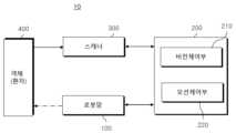
도 1을 살펴보면, 본 발명에 따른 레이저 조사 장치(10)는 스캐너(Scanner, 300), 로봇암(Robot-Arm, 100) 및 제어부(200)를 포함할 수 있다.Looking at Figure 1, the
스캐너(300)는 객체를 스캔하여 로우 데이터(Raw Data)를 수집할 수 있다. 여기서, 로우 데이터는 2차원 이미지(2D Image)와 깊이 정보(Depth Information)를 포함할 수 있다.The
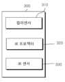
이를 위해, 스캐너(300)는, 도 2의 경우와 같이, 2차원 컬러 이미지(2D Image)를 촬영하는 컬러센서(310), 3차원 깊이 데이터(3D Depth Data)를 획득하는 IR 프로젝터(320)와 IR 센서(330)를 포함할 수 있다.For this purpose, the
IR 프로젝터(320)가 IR 광을 객체(400)의 표면, 즉 환자의 피부에 조사하면, IR 센서(330)가 객체(400)의 표면에 반사되는 IR 광을 검출하여 깊이 데이터를 획득할 수 있다.When the
컬러센서(310)는 객체의 표면을 촬영하여 2차원 컬러 이미지를 획득할 수 있다.The
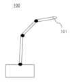
로봇암(100)은, 도 3에서와 같이, 엔드이펙터(End-Effector, EE, 101)를 장착하고, 제어부(200)의 제어에 따라 객체(400)의 표면에 레이저를 조사할 수 있다. 자세하게는, 로봇암(100)은 가이드 경로(GP)에 대응하여 객체(400)의 표면에 레이저를 조사할 수 있다. 레이저는 엔드이펙터(101)를 통해 방출될 수 있다.As shown in FIG. 3, the
이러한 로봇암(100)을 매니퓰레이터(Manipulator)라고 볼 수 있다.This
제어부(200)는 레이저 조사 장치(10)의 전반적인 기능 및 동작을 제어할 수 있다.The
제어부(200)는 비전 제어부(210)와 모션 제어부(220)를 포함할 수 있다.The
비전 제어부(210)는 스캐너(300)로부터 로우 데이터를 전송받고, 전송받은 로우 데이터를 근거로 하여 객체(400)의 3차원 이미지를 구성할 수 있다. 아울러, 비전 제어부(210)는 3차원 이미지 상에서 객체(400)의 표면상에 관심영역(Region Of Interest, ROI)을 설정할 수 있다.The
관심영역(ROI)은 레이저 조사가 필요한 부분을 포함하는 영역일 수 있다.The region of interest (ROI) may be an area containing a portion requiring laser irradiation.
예를 들면, 비전 제어부(210)는 스캐너(300)로부터 전송받은 데이터를 기반으로 하여 객체(400)의 표면의 색(Color) 또는 명암 중 적어도 하나를 판별하고, 이를 근거로 하여 관심영역을 설정할 수 있다.For example, the
자세하게는, 비전 제어부(210)는 스캐너(300)가 촬영한 객체(400)의 2차원 컬러 이미지로부터 객체(400)의 표면에서 색이 주위와 다른 부분 및/또는 명암이 주위와 다른 부분을 검출할 수 있다. 아울러, 색 및/또는 명암이 주위와 다른 부분을 포함하도록 관심영역을 설정하는 것이 가능하다.In detail, the
이하에서는, 객체의 표면에서 색 및/또는 명도가 주위와 다른 치료부분(Region Of Therapy, ROT)이라고 칭할 수 있다. 치료부분(ROT)은 사람의 피부에 생기는 점, 기미, 주근깨 등을 예로 들 수 있다.Hereinafter, the surface of the object may be referred to as a region of therapy (ROT) whose color and/or brightness is different from the surrounding area. Examples of treatment areas (ROT) include moles, spots, and freckles that appear on human skin.
모션 제어부(220)는 비전 제어부(210)가 판단한 정보를 근거로 하여 관심영역(ROI)을 지나는 가이드 경로(Guide Path, GP)를 설정하고, 상황에 따라 가이드 경로(GP)를 수정할 수 있다.The
아울러, 모션 제어부(220)는 로봇암(100)의 움직임을 제어하고, 상황에 따라 로봇암(100)을 긴급정지시켜 레이저의 조사를 긴급중단시킬 수 있다.In addition, the
본 발명에 따른 레이저 조사 장치(10)는 수동모드 및 자동모드에서 각각 동작할 수 있다.The
예를 들면, 자동모드에서는 스캐너(300)가 객체(400)의 표면을 스캔하여 객체(400)의 표면에 대한 정보를 획득하고, 이를 근거로 하여 제어부(200)가 로봇암(100)을 제어하여 객체(400)의 표면에 레이저를 조사할 수 있다.For example, in automatic mode, the
반면에, 수동모드에서는 제어권을 사용자, 예컨대 의사에게 위임할 수 있다. 수동모드에서는 로봇암(100)이 사용자가 제어에 따라 동작할 수 있다.On the other hand, in manual mode, control can be delegated to a user, such as a doctor. In manual mode, the
본 발명에 따른 레이저 조사 장치(10)를 이용한 레이저 조사 방법에 대해 첨부된 도면을 참조하여 상세히 살펴보면 아래와 같다.The laser irradiation method using the
도 4 내지 도 29는 본 발명에 따른 레이저 조사 방법에 대해 설명하기 위한 도면이다. 이하에서는 이상에서 설명한 내용에 대한 설명은 생략될 수 있다.4 to 29 are diagrams for explaining the laser irradiation method according to the present invention. Hereinafter, description of the content described above may be omitted.
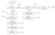
도 4를 살펴보면, 현재 모드 설정이 자동모드인지의 여부를 판단(S100)할 수 있다. 판단결과, 자동모드가 아닌 경우에는 현재 모드 설정이 수동모드인지의 여부를 판단(S110)할 수 있다.Looking at FIG. 4, it is possible to determine whether the current mode setting is automatic mode (S100). As a result of the determination, if it is not the automatic mode, it is possible to determine whether the current mode setting is the manual mode (S110).
사용자가 소정의 스위치를 이용하여 수동모드 또는 자동모드 중 어느 하나를 선택하는 것이 가능하다. 또는, 사용자가 제어부(200)에 소정의 명령을 입력하여 수동모드 또는 자동모드 중 어느 하나를 선택하여 설정하는 것이 가능하다.It is possible for the user to select either manual mode or automatic mode using a predetermined switch. Alternatively, it is possible for the user to select and set either manual mode or automatic mode by entering a predetermined command into the
제 S110단계에서의 판단결과, 수동모드가 아닌 경우에는 미리 설정된 다른 기능(Default)을 수행(S120)할 수 있다.As a result of the determination in step S110, if the manual mode is not selected, another preset function (default) can be performed (S120).
반면에, 판단결과 수동모드인 경우에는 수동모드 설정을 확인(S130)하고, 사용자에게 제어권을 위임(S140)할 수 있다.On the other hand, if the determination result is manual mode, the manual mode setting can be confirmed (S130) and control rights can be delegated to the user (S140).
여기서, 제어권을 사용자에게 위임한다는 것은 제어부(200)가 스스로 판단하여 로봇암(100)을 동작시키는 것을 제한하는 것을 의미할 수 있다.Here, delegating control to the user may mean restricting the
수동모드에서는 사용자가 자신의 힘으로 로봇암(100)을 동작시키면서 레이저 치료를 수행할 수 있다.In the manual mode, the user can perform laser treatment while operating the
한편, 제 S100단계에서 판단결과 자동모드인 경우에는 스캐너(300)가 제어부(200)의 제어에 따라 객체(400)의 표면을 스캔(S150)할 수 있다. 스캐너(300)의 스캔에 따라 2차원 이미지와 깊이 정보를 포함하는 로우 데이터가 생성될 수 있다.Meanwhile, in the case of the automatic mode as a result of the determination in step S100, the
이후, 비전 제어부(210)는 스캐너(300)가 획득한 로우 데이터를 근거로 하여 3차원 이미지를 구성(S160)할 수 있다.Thereafter, the
예를 들면, 도 5의 (A)와 같은 사람의 머리 형태의 석고상(Plaster Cast)을 스캔하면, 도 5의 (B)와 같은 형태로 3차원 이미지가 구성될 수 있다.For example, when a plaster cast in the shape of a human head, as shown in (A) of FIG. 5, is scanned, a three-dimensional image may be formed in the form as shown in (B) of FIG. 5.
이하에서는 설명의 편의를 위해 객체(400)에 대해 사람의 머리 형태의 석고상을 일례로 들어 설명하기로 한다.Hereinafter, for convenience of explanation, the
3차원 이미지를 구성한 이후, 3차원 이미지 상에서 객체(400)의 표면상에 관심영역(ROI)을 설정(S170)할 수 있다.After constructing the 3D image, a region of interest (ROI) can be set (S170) on the surface of the
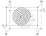
예를 들면, 도 5의 (C)의 경우와 같이 3차원 이미지 상에서 객체(400)의 표면에 제 1 코너 포인트(Pcor, 1), 제 2 코너 포인트(Pcor, 2), 제 3 코너 포인트(Pcor, 3) 및 제 4 코너 포인트(Pcor, 4)를 설정할 수 있다. 이후, 제 1, 2, 3, 4 코너 포인트를 꼭지점으로 하여 구획되는 영역을 관심영역(ROI)으로 설정할 수 있다.For example, as in the case of Figure 5 (C), a first corner point (Pcor, 1), a second corner point (Pcor, 2), and a third corner point (Pcor, 1) are placed on the surface of the
여기서는, 4개의 코너 포인트를 이용하여 관심영역(ROI)을 설정하였으나, 상황에 따라 사용되는 코너 포인트의 개수는 변경될 수 있다. 예를 들면, 3개 이상의 코너 포인트를 이용하여 관심영역(ROI)을 설정하는 것이 가능하다.Here, the region of interest (ROI) was set using four corner points, but the number of corner points used may change depending on the situation. For example, it is possible to set a region of interest (ROI) using three or more corner points.
이하에서는, 설명의 편의를 위해 제 1 코너 포인트(Pcor, 1)를 제 1 포인트(P1), 제 2 코너 포인트(Pcor, 2)를 제 2 포인트(P2), 제 3 코너 포인트(Pcor, 3)를 제 3 포인트(P3), 제 4 코너 포인트(Pcor, 4)를 제 4 포인트(P4)라고 칭할 수 있다.Hereinafter, for convenience of explanation, the first corner point (Pcor, 1) is referred to as the first point (P1), the second corner point (Pcor, 2) is referred to as the second point (P2), and the third corner point (Pcor, 3). ) may be referred to as the third point (P3), and the fourth corner point (Pcor, 4) may be referred to as the fourth point (P4).
이후, 관심영역(ROI)을 지나는 가이드 경로(GP)를 설정(S180)할 수 있다.Afterwards, a guide path (GP) passing through the region of interest (ROI) can be set (S180).
예를 들면, 도 6에서와 같이, 관심영역(ROI) 내에서 가이드 경로(GP)를 설정하는 것이 가능하다.For example, as shown in FIG. 6, it is possible to set a guide path (GP) within a region of interest (ROI).
가이드 경로(GP)의 시작지점, 즉 레이저를 조사하기 시작하는 지점은 Ps로 표시하고, 가이드 경로(GP)의 종료지점, 즉 레이저 조사가 종료되는 지점은 Pt로 표시하였다.The starting point of the guide path (GP), i.e., the point where laser irradiation begins, is denoted as Ps, and the end point of the guide path (GP), i.e., the point where laser irradiation ends, is denoted as Pt.
이후, 가이드 경로(GP)에 대응하여 레이저를 조사(S190)할 수 있다.Afterwards, the laser may be irradiated (S190) in response to the guide path (GP).
가이드 경로(GP)는 로봇암(100)이 레이저를 조사하는 경로를 포함할 수 있다. 다르게 표현하면, 로봇암(100)은 가이드 경로(GP)에 대응하여 이동하면서 객체의 표면에 레이저를 조사하는 것이 가능하다.The guide path (GP) may include a path along which the
가이드 경로(GP)는 레이저의 탄착지점을 연결한 경로를 포함하는 것으로 볼 수 있다.The guide path (GP) can be viewed as including a path connecting the laser's impact point.
한편, 관심영역(ROI)은 객체(400)의 표면의 색 또는 명암 중 적어도 하나에 근거하여 설정될 수 있다. 이에 대해, 첨부된 도 7을 참조하여 살펴보면 아래와 같다.Meanwhile, the region of interest (ROI) may be set based on at least one of the color or brightness of the surface of the
도 7을 살펴보면, 관심영역(ROI)을 설정하는 단계(S170)에서는 먼저 객체(400)의 표면의 색 및/또는 명암을 판별(S171)할 수 있다. 객체(400)의 2차원 컬러 이미지로부터 객체(400)의 표면의 색 및/또는 명암을 판단할 수 있다.Referring to FIG. 7 , in the step of setting a region of interest (ROI) (S170), the color and/or brightness of the surface of the
이후, 판별값을 비교(S172)할 수 있다.Afterwards, the discrimination values can be compared (S172).
이후, 판별값을 비교/분석하여 객체(400)의 표면에서 색 또는 명암 중 적어도 하나가 주위와 다른 치료부분(ROT)을 검출(S173)할 수 있다. 다르게 표현하면, 객체(400)의 표면에서 색 또는 명도 중 적어도 하나를 근거로 하여 일반부분(RON)과 치료부분(ROT)을 구분할 수 있다.Thereafter, the discrimination value may be compared/analyzed to detect a treatment area (ROT) on the surface of the
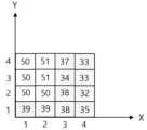
예를 들어, 도 8의 경우와 같이, 총 16개의 단위 영역(Unit Area)이 4×4 형식으로 배열되어 이루어진 영역을 가정하여 보자. 도 8에서 각각의 단위 영역에 표시된 숫자는 명도값(Brightness Value)을 의미할 수 있다.For example, as in the case of FIG. 8, let's assume an area consisting of a total of 16 unit areas arranged in a 4×4 format. In FIG. 8, the numbers displayed in each unit area may mean brightness value.
여기서, 기준 명도값을 40이라고 가정하면, 명도값이 40보다 작은 (1, 1), (2, 1), (3, 1), (3, 2), (3, 3), (3, 4), (4, 1), (4, 2), (4, 3) 및 (4, 4)의 단위 영역을 치료 영역(ROT)으로 판별할 수 있다. 나머지 부분은 일반부분(Region Of Normal, RON)이라고 할 수 있다. 치료부분(ROT)의 명도는 다른 부분, 즉 일반부분(RON)의 명도보다 더 낮아서 상대적으로 더 어두울 수 있다. 이와 유사하게, 치료부분(ROT)의 컬러는 일반부분(RON)의 컬러보다 더 짙을 수 있다. 컬러가 짙다는 것은 더 어둡다는 것을 의미할 수 있다.Here, assuming that the standard brightness value is 40, (1, 1), (2, 1), (3, 1), (3, 2), (3, 3), (3, The unit areas of 4), (4, 1), (4, 2), (4, 3), and (4, 4) can be determined as the treatment area (ROT). The remaining part can be called the Region Of Normal (RON). The brightness of the treated area (ROT) may be lower and relatively darker than the brightness of the other area, that is, the normal area (RON). Similarly, the color of the treated area (ROT) may be darker than the color of the normal area (RON). Darker colors can mean darker.
이처럼, 치료부분(ROT)의 명도값은 미리 설정된 기준 명도값보다 더 낮은 부분이라고 할 수도 있다.In this way, the brightness value of the treatment area (ROT) can be said to be a part that is lower than the preset standard brightness value.
기준 명도값은 객체(400)의 표면의 상태, 특징, 컬러톤 등의 요인에 따라 다양하게 변경될 수 있다.The reference brightness value may vary depending on factors such as the surface condition, characteristics, and color tone of the
예를 들어, 얼굴이 전체적으로 밝은 백인의 경우에는 기준 명도값을 상대적으로 높게 설정할 수 있다. 그 이유는 얼굴이 전체적으로 밝은 경우에는 점, 기미 등의 치료가 필요한 부분, 즉 치료부분이 더 두드러지게 보일 수 있기 때문이다.For example, in the case of a white person with an overall bright face, the standard brightness value can be set relatively high. This is because if the overall face is bright, the areas that require treatment, such as moles and freckles, may appear more prominently.
반면에, 얼굴이 백인에 비해 전체적으로 어두운 황인종의 경우에는 기준 명도값을 백인에 비해 상대적으로 낮게 설정할 수 있다.On the other hand, in the case of yellow people whose faces are overall darker than those of white people, the standard brightness value can be set relatively lower than that of white people.
치료부분(ROT)을 검출한 이후에, 관심영역(ROI)을 설정(S174)할 수 있다.After detecting the treatment area (ROT), a region of interest (ROI) can be set (S174).
관심영역(ROI)은 치료영역(ROT)을 포함할 수 있다.The region of interest (ROI) may include a region of treatment (ROT).
도 9의 (A)의 경우와 같이, 객체(400)의 표면상의 소정 영역(R1) 상에 주위의 일반영역(RON)과 명도 및/또는 컬러가 다른 치료영역(ROT)이 포함되어 있는 경우를 가정하여 보자. 도 9에서 치료영역(ROT)의 형태는 설명의 편의를 위해 임의로 설정한 것으로 본 발명이 이에 한정되는 것은 아니다.As in the case of Figure 9 (A), when a treatment area (ROT) that is different in brightness and/or color from the surrounding general area (RON) is included on a predetermined area (R1) on the surface of the
이러한 경우, 도 9의 (B)와 같이, 제 1 포인트(P1)와 제 2 포인트(P2)를 연결하는 제 1 라인(L1)이 치료영역(ROT)과 접하고, 제 2 포인트(P2)와 제 3 포인트(P3)를 연결하는 제 2 라인(L2)이 치료영역(ROT)과 접하고, 제 3 포인트(P3)와 제 4 포인트(P4)를 연결하는 제 3 라인(L3)이 치료영역(ROT)과 접하고, 제 4 포인트(P4)와 제 1 포인트(P1)를 연결하는 제 4 라인(L4)이 치료영역(ROT)과 접하도록 제 1, 2, 3, 4 포인트(P1, P2, P3, P4)를 설정할 수 있다.In this case, as shown in Figure 9 (B), the first line (L1) connecting the first point (P1) and the second point (P2) is in contact with the treatment area (ROT), and the second point (P2) The second line (L2) connecting the third point (P3) is in contact with the treatment area (ROT), and the third line (L3) connecting the third point (P3) and the fourth point (P4) is in contact with the treatment area (ROT). The first, second, third and fourth points (P1, P2, P3, P4) can be set.
아울러, 제 1, 2, 3, 4 포인트(P1, P2, P3, P4)로 구획되는 영역을 관심영역(ROI)으로 설정할 수 있다.In addition, the area divided by the first, second, third, and fourth points (P1, P2, P3, and P4) can be set as a region of interest (ROI).
이러한 경우, 치료영역(ROT)은 관심영역(ROI) 내에 포함될 수 있다. 아울러, 관심영역(ROI)은 치료영역(ROT) 뿐 아니라 일반영역(RON)의 일부도 포함할 수 있다.In this case, the region of treatment (ROT) may be included within the region of interest (ROI). In addition, the region of interest (ROI) may include not only the treatment region (ROT) but also a portion of the general region (RON).
이하에서는, 일반영역(RON)에서 관심영역(ROI)에 포함된 부분을 제 2 일반영역(RON2)이라고 하고, 일반영역(RON)에서 관심영역(ROI)에 포함되지 않는 부분을 제 1 일반영역(RON1)이라고 할 수 있다.Hereinafter, the part of the general area (RON) included in the region of interest (ROI) is referred to as the second general area (RON2), and the part of the general area (RON) not included in the region of interest (ROI) is referred to as the first general area. It can be said to be (RON1).
도 9에서는 관심영역(ROI)을 설정할 때, 인접하는 두 개의 포인트를 연결하는 라인이 치료영역(ROT)에 접하는 경우만을 설명하였지만, 본 발명은 이에 한정되지 않을 수 있다.In FIG. 9 , only the case where a line connecting two adjacent points touches a region of treatment (ROT) is described when setting a region of interest (ROI), but the present invention may not be limited to this.
예를 들면, 도 10의 경우와 같이, 인접하는 두 개의 포인트를 연결하는 라인(L1, L2, L3, L4) 중 적어도 하나는 치료영역(ROT)에 접하지 않을 수 있다.For example, as in the case of FIG. 10, at least one of the lines L1, L2, L3, and L4 connecting two adjacent points may not be in contact with the treatment area ROT.
이처럼, 관심영역(ROI)을 설정하는 방법은 다양하게 변경될 수 있다.In this way, the method of setting the region of interest (ROI) can be changed in various ways.
만약, 치료영역(ROT)의 형태가 다각형 형태인 경우에는 포인트의 설정 위치에 따라 치료영역(ROT)과 관심영역(ROI)이 동일한 경우도 발생할 수 있다.If the shape of the treatment area (ROT) is polygonal, the treatment area (ROT) and the region of interest (ROI) may be the same depending on the point setting location.
한편, 가이드 경로(GP)는 치료영역(GOT) 내에서 설정되는 것이 가능하다.Meanwhile, the guide path (GP) can be set within the treatment area (GOT).
예를 들면, 도 11의 경우와 같이, 치료영역(ROT) 내에서 지그재그 형태로 가이드 경로(GP)를 설정하는 것이 가능하다.For example, as in the case of FIG. 11, it is possible to set the guide path (GP) in a zigzag shape within the treatment area (ROT).
이처럼, 가이드 경로(GP)는 치료영역(ROT)을 지나고, 레이저는 치료영역(ROT)에 조사되는 것이 가능하다.In this way, it is possible for the guide path (GP) to pass through the treatment area (ROT) and the laser to be irradiated to the treatment area (ROT).
한편, 레이저 조사의 시작단계와 종료단계에서는 레이저의 강도(Intensity, Strength) 및/또는 주파수를 조절하는 것이 가능하다. 이에 대해 살펴보면 아래와 같다.Meanwhile, it is possible to adjust the intensity and/or frequency of the laser at the start and end stages of laser irradiation. Looking at this, it is as follows.
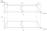
도 12의 (A)를 살펴보면, 레이저를 조사하는 단계의 시작단계에서는 레이저의 강도(Intensity, Strength) 또는 주파수 중 적어도 하나를 점진적으로 상승시키고, 조사단계의 종료단계에서는 레이저의 강도 또는 주파수 중 적어도 하나를 점진적으로 감소시킬 수 있다.Looking at (A) of FIG. 12, at the beginning of the laser irradiation step, at least one of the intensity or frequency of the laser is gradually increased, and at the end of the irradiation step, at least one of the intensity or frequency of the laser is increased. One can gradually reduce it.
이하에서는, 레이저의 시작단계를 가속구간(D1)이라 칭하고, 레이저의 종료단계를 감소구간(D3)이라고 칭할 수 있다.Hereinafter, the starting stage of the laser may be referred to as an acceleration section (D1), and the ending stage of the laser may be referred to as a reduction section (D3).
도 12의 (B)와 같이, 가속구간(D1)에서는 로봇암(100)의 이동속도가 증가할 수 있다. 즉, 로봇암(100)이 가속될 수 있다. 가속구간(D1)의 발생이유는 로봇암(100)을 동작시키는 모터에 전력을 공급하는 시점부터 원하는 회전속도에 도달하는데 까지 어느 정도의 시간이 소요되기 때문이다.As shown in (B) of FIG. 12, the moving speed of the
아울러, 감속구간(D3)에서는 로봇암(100)의 이동속도가 감소할 수 있다. 즉, 로봇암(100)이 감속될 수 있다. 감속구간(D3)이 발생하는 이유도 가속구간(D1)과 유사하게 로봇암(100)을 동작시키는 모터에 전력 공급을 차단하는 시점부터 모터가 정지하는데 까지 어느 정도의 시간이 소요되기 때문이다.In addition, the moving speed of the
이와 같이, 가속구간(D1)에서 레이저의 강도 및/또는 주파수를 점진적으로 상승시키고, 감속구간(D3)에서 레이저의 강도 및/또는 주파수를 점진적으로 감소시키게 되면, 레이저를 보다 균일하게 조사하는 것이 가능할 수 있다.In this way, if the intensity and/or frequency of the laser is gradually increased in the acceleration section (D1) and the intensity and/or frequency of the laser is gradually decreased in the deceleration section (D3), it is possible to irradiate the laser more uniformly. It may be possible.
레이저의 강도 및/또는 주파수는 로봇암(100)의 이동속도와 비례할 수 있다.The intensity and/or frequency of the laser may be proportional to the moving speed of the
가속구간(D1)과 감속구간(D3)의 사이구간은 유지구간(D2)이라고 할 수 있다.The section between the acceleration section (D1) and the deceleration section (D3) can be called the maintenance section (D2).
유지구간(D2)에서는 레이저의 조사가 중단되는 않는다면 레이저의 강도 및/또는 주파수는 대략 일정하게 유지될 수 있다.In the maintenance period D2, the intensity and/or frequency of the laser may be maintained approximately constant as long as the laser irradiation is not stopped.
유지구간(D2)에서는 로봇암(100)의 속도는 대략 일정하게 유지될 수 있다. 다르게 표현하면, 로봇암(100)의 가속이 종료되는 시점부터 감속이 시작되는 시점까지의 기간(D2)동안 로봇암(100)의 속도는 일정하게 유지될 수 있다.In the maintenance period D2, the speed of the
도 13의 (A)와 같이, 가속구간(D1)에서 계단형으로 레이저의 강도 및/또는 주파수를 증가시키거나, 감속구간(D3)에서 계단형으로 레이저의 강도 및/또는 주파수를 감소시키는 경우도 가능할 수 있다. 이러한 경우에도, 가속구간(D1)에서 레이저의 강도 및/또는 주파수를 점진적으로 상승시키고, 감속구간(D3)에서 레이저의 강도 및/또는 주파수를 점진적으로 감소시키는 것으로 볼 수 있다.As shown in Figure 13 (A), when the intensity and/or frequency of the laser is increased in a stepwise manner in the acceleration section (D1), or the intensity and/or frequency of the laser is decreased in a stepwise manner in the deceleration section (D3) It may also be possible. Even in this case, it can be seen that the intensity and/or frequency of the laser is gradually increased in the acceleration section (D1) and the intensity and/or frequency of the laser is gradually decreased in the deceleration section (D3).
한편, 가이드 경로(GP)는 관심영역(ROI) 내에서 치료영역(ROT)을 벗어나는 것이 가능할 수 있다.Meanwhile, the guide path (GP) may be able to deviate from the region of treatment (ROT) within the region of interest (ROI).
예를 들면, 도 14의 경우와 같이, 관심영역(ROI)은 치료부분(ROT)과 일반부분, 즉 제 2 일반부분(RON2)을 함께 포함하는 경우에, 가이드 경로(GP)는 치료부분(ROT)과 제 2 일반부분(RON2)을 모두 통과할 수 있다. 이러한 경우, 레이저는 치료부분(ROT)에 대응해서 턴-온(Trun-On)되고, 제 2 일반부분(RON2)에 대응해서 턴-오프(Turn-Off)되는 것이 가능하다.For example, as in the case of Figure 14, when the region of interest (ROI) includes both the treatment part (ROT) and the general part, that is, the second general part (RON2), the guide path (GP) is the treatment part ( You can pass both the ROT) and the second general section (RON2). In this case, it is possible for the laser to be turned on in response to the treatment portion (ROT) and turned off in response to the second general portion (RON2).
이처럼, 관심영역(ROI) 내에서 치료영역(ROT)의 형태와는 관계없이 가이드 경로(GP)를 설정하는 것이 가능하다.In this way, it is possible to set a guide path (GP) within the region of interest (ROI) regardless of the shape of the region of treatment (ROT).
이러한 경우, 가이드 경로(GP)는 치료영역(ROT)을 지나는 부분과 치료영역(ROT)을 벗어나서 제 2 일반영역(RON2)을 지나는 부분(T1, T2, T3, T4)을 포함할 수 있다.In this case, the guide path (GP) may include a part that passes through the treatment area (ROT) and a part (T1, T2, T3, T4) that goes beyond the treatment area (ROT) and passes through the second general area (RON2).
로봇암(100)은, 도 15에 나타난 바와 같이, 가이드 경로(GP)에서 제 2 일반영역(RON2)을 지나는 부분에 대응해서는 레이저를 턴-오프(Turn-Off)시킬 수 있다. 다르게 표현하면, 로봇암(100)이 가이드 경로(GP)를 따라 레이저를 조사하는 과정에서 객체(400)의 표면의 색 또는 명도 중 적어도 하나에 따라 레이저를 온/오프시키는 것으로 볼 수 있다. 즉, 로봇암(100)이 가이드 경로(GP)에 대응하여 이동하다가 주위보다 색이 더 짙거나 명도가 더 낮은 부분, 즉 치료영역(ROT)에 대응되면 레이저를 턴-온(Turn-On)시키고, 주위보다 색이 더 옅거나 명도가 더 높은 부분, 즉 일반영역(RON)에 대응되면 레이저를 턴-오프시킬 수 있는 것이다.As shown in FIG. 15, the
도 15를 살펴보면 로봇암(100)이 제 2 일반영역(RON2)을 지나는 기간(T1, T2, T3, T4) 동안 레이저의 주파수 및/또는 강도가 거의 0으로 설정되는 것을 알 수 있다.Looking at FIG. 15, it can be seen that the frequency and/or intensity of the laser is set to almost 0 during the period (T1, T2, T3, T4) during which the
이러한 경우, 로봇암의 움직임을 대략 일정하게 유지할 수 있어서 치료의 정밀도를 향상시킬 수 있다.In this case, the movement of the robot arm can be kept approximately constant, thereby improving the precision of treatment.
한편, 모션 제어부(220)의 제어 하에, 치료부분(ROT)의 색 및/또는 명도의 정도에 따라 레이저의 주파수, 조사시간, 조사회수 또는 강도(Intensity) 중 적어도 하나를 조절하는 것이 가능하다. 이에 대해 살펴보면 아래와 같다.Meanwhile, under the control of the
도 16을 살펴보면, 치료부분(ROT)은 제 1 치료부분(ROT1)과 제 2 치료부분(ROT2)을 포함할 수 있다. 여기서, 제 2 치료부분(ROT2)의 색은 제 1 치료부분(ROT1)의 색보다 더 짙거나, 제 2 치료부분(ROT2)의 명도는 제 1 치료부분(ROT1)의 명도보다 더 낮을 수 있다. 다르게 표현하면, 제 2 치료부분(ROT2)의 색의 짙음의 정도는 미리 설정된 임계값보다 더 짙고, 제 1 치료부분(ROT1)의 색의 짙음의 정도는 미리 설정된 임계값보다 더 옅은 것으로 볼 수 있다. 또는, 제 2 치료부분(ROT2)의 명도는 미리 설정된 임계명도값보다 더 낮고, 제 1 치료부분(ROT1)의 명도는 미리 설정된 임계명도값보다 더 높은 것으로 볼 수 있다.Referring to FIG. 16, the treatment portion (ROT) may include a first treatment portion (ROT1) and a second treatment portion (ROT2). Here, the color of the second treatment part (ROT2) may be darker than the color of the first treatment part (ROT1), or the brightness of the second treatment part (ROT2) may be lower than the brightness of the first treatment part (ROT1). . Expressed differently, the degree of color darkness of the second treatment part (ROT2) can be seen as being darker than the preset threshold, and the degree of color density of the first treatment part (ROT1) can be seen as being lighter than the preset threshold. there is. Alternatively, the brightness of the second treatment portion (ROT2) may be lower than the preset threshold brightness value, and the brightness of the first treatment portion (ROT1) may be viewed as being higher than the preset threshold brightness value.
제 2 치료부분(ROT2)은 제 1 치료부분(ROT1)에 비해 집중적인 치료가 필요한 부분이라고 볼 수 있다.The second treatment part (ROT2) can be seen as a part that requires more intensive treatment than the first treatment part (ROT1).
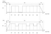
레이저의 시작지점(Ps)에서 시작하여 순차적으로 가이드 경로(GP) 상에서 제 2 일반영역(RON2)과 제 1 치료영역(ROT1)의 경계점을 제 1 지점(X1)이라 하고, 제 1 치료영역(ROT1)과 제 2 치료영역(ROT2)의 경계점을 제 2 지점(X2)이라 하고, 제 2 치료영역(ROT2)과 제 2 일반영역(RON2)의 경계점을 제 3 지점(X3)이라 하고, 제 2 일반영역(RON2)과 제 1 치료영역(ROT1)의 경계점을 제 4 지점(X4)이라 하고, 제 1 치료영역(ROT1)과 제 2 치료영역(ROT2)의 경계점을 제 5 지점(X5)이라 하고, 제 2 치료영역(ROT2)과 제 1 치료영역(ROT1)의 경계점을 제 6 지점(X6)이라 하고, 제 1 치료영역(ROT1)과 제 2 치료영역(ROT2)의 경계점을 제 7 지점(X7)이라 하고, 제 2 치료영역(ROT2)과 제 1 치료영역(ROT1)의 경계점을 제 8 지점(X8)이라 가정하자.Starting from the starting point of the laser (Ps), the boundary point between the second general area (RON2) and the first treatment area (ROT1) on the guide path (GP) is called the first point (X1), and the first treatment area ( The boundary point between the second treatment area (ROT1) and the second treatment area (ROT2) is called the second point (X2), the boundary point between the second treatment area (ROT2) and the second general area (RON2) is called the third point (X3), and the boundary point between the second treatment area (ROT2) and the second general area (RON2) is called the third point (X3). 2 The boundary point between the general area (RON2) and the first treatment area (ROT1) is called the fourth point (X4), and the boundary point between the first treatment area (ROT1) and the second treatment area (ROT2) is called the fifth point (X5). The boundary point between the second treatment area (ROT2) and the first treatment area (ROT1) is called the 6th point (X6), and the boundary point between the first treatment area (ROT1) and the second treatment area (ROT2) is called the 7th point. Let us assume that the point is X7, and that the boundary point between the second treatment area (ROT2) and the first treatment area (ROT1) is the eighth point (X8).
도 17에서와 같이, 레이저의 시작지점(Ps)부터 제 1 지점(X1)의 사이 및 제 3 지점(X3)부터 제 4 지점(X4)의 사이에서는 레이저를 턴-오프시킬 수 있다. 다르게 표현하면, Ps-X1 구간 및 X3-X4구간은 제 2 일반영역(RON2)에 포함되는 구간이기 때문에 로봇암(100)이 레이저를 조사하지 않을 수 있다.As shown in FIG. 17, the laser can be turned off between the laser start point (Ps) and the first point (X1) and between the third point (X3) and the fourth point (X4). In other words, the Ps-X1 section and the X3-X4 section are included in the second general area RON2, so the
X1-X2 구간, X4-X5 구간, X6-X7 구간 및 제 8 지점(X8)부터 감속구간(D3)이 시작되기 이전까지의 구간에서는 레이저의 주파수를 제 1 주파수(f1)로 설정할 수 있다.In the X1-X2 section,
반면에, X2-X3 구간, X5-X6 구간 및 X7-X8 구간에서는 레이저의 주파수를 제 1 주파수(f1)보다 높은 제 2 주파수(f2)로 설정할 수 있다.On the other hand, in the X2-X3 section, X5-X6 section, and X7-X8 section, the frequency of the laser can be set to a second frequency (f2) that is higher than the first frequency (f1).
이러한 경우, 제 2 치료영역(ROT2)에 상대적으로 더 강한 레이저가 조사될 수 있어서 치료 효율이 향상될 수 있다.In this case, a relatively stronger laser can be irradiated to the second treatment area (ROT2), thereby improving treatment efficiency.
도 18의 (A)를 살펴보면, X1-X3구간, X4-X8 구간 및 제 8 지점(X8)부터 감속구간(D3)이 시작되기 이전까지의 구간에서는 레이저의 주파수를 제 1 주파수(f1)로 동일하게 설정할 수 있다.Looking at (A) of Figure 18, in the section X1-X3, section X4-X8, and the section from the 8th point ( It can be set the same way.
이처럼, 레이저의 주파수를 유지한 상태에서, 도 18의 (B)와 같이, 가속구간(D1)이 종료되는 지점부터 제 2 지점(X2)까지의 구간, X3-X5 구간, X6-X7 구간 및 제 8 지점(X8)부터 감속구간(D3)이 시작되기 이전까지의 구간에서는 로봇암(100)의 이동속도를 제 1 속도(V1)로 설정할 수 있다. 반면에, X2-X3구간, X5-X6구간 및 X7-X8구간에서는 로봇암(100)의 이동속도를 제 1 속도(V1)보다 느린 제 2 속도(V2)로 설정할 수 있다.In this way, while maintaining the frequency of the laser, as shown in (B) of Figure 18, the section from the point where the acceleration section (D1) ends to the second point (X2), the section X3-X5, the section X6-X7, and In the section from the eighth point (X8) to before the start of the deceleration section (D3), the moving speed of the
이러한 경우, 제 2 치료영역(ROT2)에 상대적으로 더 오랫동안 레이저가 조사될 수 있어서 치료 효율이 향상될 수 있다.In this case, the laser can be irradiated to the second treatment area (ROT2) for a relatively longer period of time, thereby improving treatment efficiency.
한편, 제 2 치료영역(ROT2)에 대해서는 치료 횟수를 제 1 치료영역(ROT1)에 비해 상대적으로 더 많게 설정할 수 있다. 이에 대해, 첨부된 도 19를 참조하여 설명한다. 도 19의 (A)는 로봇암(100)이 관심영역(ROI) 내에서 가이드 경로(GP)에 따라 객체(400)의 표면에 레이저를 조사하여 레이저 치료를 1회차 실시하는 것이고, 도 19의 (B)는 1회차 치료가 종료된 이후에 실시하는 2회차 치료에 해당될 수 있다.Meanwhile, the number of treatments for the second treatment area (ROT2) can be set to be relatively greater than that for the first treatment area (ROT1). This will be explained with reference to the attached FIG. 19. In Figure 19 (A), the
도 19의 (A)를 살펴보면, 1회차 치료과정에서는, X1-X3구간, X4-X8 구간 및 제 8 지점(X8)부터 감속구간(D3)이 시작되기 이전까지의 구간에서는 로봇암(100)이 레이저를 조사하고, 여기서 레이저의 주파수를 제 1 주파수(f1)로 동일하게 설정할 수 있다.Looking at (A) of FIG. 19, in the first treatment process, the
도 19의 (B)를 살펴보면, 2회차 치료과정에서는, 제 2 치료영역(ROT2)에 대응하는 X2-X3구간, X5-X6구간 및 X7-X8구간에서는 로보암(100)이 레이저를 조사하고, 여기서 레이저의 주파수를 제 2 주파수(f2)와 제 1 주파수(f1)의 차이만큼으로 동일하게 설정할 수 있다.Looking at (B) of FIG. 19, in the second treatment process, the
그러면, 제 2 치료영역(ROT2)에서는 제 2 주파수(f2)의 레이저가 조사되는 것과 유사한 치료효과가 발생할 수 있다.Then, a treatment effect similar to that in which a laser of the second frequency f2 is irradiated may occur in the second treatment area ROT2.
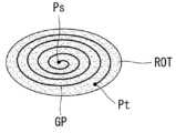
한편, 가이드 경로(GP)를 나선형(Spiral)으로 설정하는 것이 바람직할 수 있다. 이에 대해 살펴보면 아래와 같다.Meanwhile, it may be desirable to set the guide path (GP) to a spiral shape. Looking at this, it is as follows.
도 20을 살펴보면, 관심영역(ROI)의 중앙영역에서 시작하여 외곽에서 종료되도록 나선형의 가이드 경로(GP)를 설정하는 것이 가능하다. 즉, 가이드 경로(GP)의 시작지점(Ps)이 종료지점(Pt)보다 상대적으로 더 관심영역(ROI)의 중앙영역에 위치할 수 있다.Looking at Figure 20, it is possible to set a spiral guide path (GP) to start from the central area of the region of interest (ROI) and end at the outside. In other words, the starting point (Ps) of the guide path (GP) may be located relatively more in the central area of the region of interest (ROI) than the ending point (Pt).
이처럼, 가이드 경로(GP)를 나선형으로 설정하게 되면 로봇암(100)이 급격하게 방향전환을 하는 것을 방지함으로써 보다 균일하게 레이저를 객체(400)의 표면에 조사할 수 있다.In this way, if the guide path (GP) is set to be spiral, the
나선형의 가이드 경로(GP)를 설정하는 경우에도, 도 21의 경우와 같이, 가이드 경로(GP)는 제 2 일반영역(RON2)과 치료영역(ROT)을 함께 지나는 것이 가능하다.Even when setting a spiral guide path (GP), as in the case of FIG. 21, it is possible for the guide path (GP) to pass through the second general area (RON2) and the treatment area (ROT) together.
이러한 경우에도, 가이드 경로(GP) 상에서 제 2 일반영역(RON2)을 지나는 부분(T11, T12, T13)에서는 레이저를 턴-오프시킬 수 있다.Even in this case, the laser can be turned off in the portions (T11, T12, and T13) passing through the second general area (RON2) on the guide path (GP).
도 22를 살펴보면, 가이드 경로(GP)는 관심영역(ROI)을 벗어나는 것도 가능할 수 있다. 이러한 경우에는, 치료영역(ROT)에 보다 촘촘하게 레이저를 조사하여 치료 효과를 높일 수 있다.Looking at FIG. 22, it may be possible for the guide path (GP) to deviate from the region of interest (ROI). In this case, the treatment effect can be improved by irradiating the laser more closely to the treatment area (ROT).
가이드 경로(GP) 상에서 관심영역(ROI)을 벗어나는 부분에 대응해서는 레이저를 턴-오프시킬 수 있다.The laser can be turned off in response to a portion of the guide path (GP) that falls outside the region of interest (ROI).
가이드 경로(GP)는 나선형인 조건 하에서 그 형태는 다양하게 변경될 수 있다.The shape of the guide path (GP) can be changed in various ways under the condition that it is spiral.
예를 들면, 도 23의 경우와 같이, 치료영역(ROT)이 타원형인 경우에 가이드 경로(GP)도 타원형으로 설정하는 것이 가능하다.For example, as in the case of FIG. 23, when the treatment area (ROT) is oval, it is possible to set the guide path (GP) to be oval as well.
본 발명에서는 치료 효과를 높이고, 치료 정밀도를 향상시키기 위해, 도 24의 경우와 같이, 로봇암(100)의 엔드이펙터(101)가 객체(400)의 표면에 대략 수직으로 레이저를 조사하는 것이 바람직할 수 있다.In the present invention, in order to increase the treatment effect and improve the treatment precision, it is preferable that the
이를 위해, 로봇암(100)은 충분한 자유도(Degree Of Freedom, DOF)를 갖는 것이 바람직할 수 있다. 자세하게는, 로봇암(100)은 적어도 5 자유도를 갖는 것이 바람직할 수 있으며, 예외적인 상황에 대비하여 6 자유도를 갖는 것이 더욱 바람직할 수 있다.For this purpose, it may be desirable for the
본 발명에 따른 레이저 조사 장치(10)를 이용하여 실시한 레이저 조사 실험이 도 25 내지 도 26에 개시되어 있다.Laser irradiation experiments conducted using the
도 25를 살펴보면, 레이저 발사부(Laser Emitter), 모터(Motor), 모터 드라이브(Motor Drive), 반사미러(Mirror) 및 엔드이펙터(EE)를 포함하는 로봇암(100)이 사람 머리 형태의 석고상인 객체(400)의 표면에 레이저를 조사하는 경우의 일례가 개시되어 있다.Looking at Figure 25, the
모터와 모터 드라이브는 로봇암(100)을 동작시킬 수 있다.The motor and motor drive can operate the
레이저 발사부가 레이저를 발사하면 반사미러가 이를 소정 각도로 반사하여 엔드이펙터에 도달하도록 할 수 있다.When the laser emitter fires a laser, the reflection mirror reflects it at a predetermined angle so that it reaches the end effector.
그러면, 엔드이펙터가 레이저를 객체(400)의 표면에 조사할 수 있다.Then, the end effector can irradiate the laser onto the surface of the
도 26을 살펴보면, 가이드 경로(GP)가 객체(400)의 표면상에 나선형으로 설정되는 것을 확인할 수 있다. 도 26은 객체(400)의 표면에 레이저가 조사되는 것을 일정 기간 동안 촬영하여 가이드 경로(GP)와 같은 형태로 구현한 것으로 볼 수 있다.Looking at FIG. 26, it can be seen that the guide path GP is set in a spiral shape on the surface of the
한편, 상황에 따라 레이저 조사를 정지시키거나 혹은 가이드 경로를 수정하는 것이 가능하다. 이에 대해 살펴보면 아래와 같다.Meanwhile, it is possible to stop laser irradiation or modify the guide path depending on the situation. Looking at this, it is as follows.
도 27을 살펴보면, 가이드 경로(GP)를 설정하거나 레이저를 조사한 이후에 객체(400)의 움직임의 여부를 판단(S200)할 수 있다. 예를 들면, 객체(400)의 사람의 머리인 경우, 코, 양쪽 눈 등 특정 부위를 관찰하여 해당 부위에 움직임이 있는지를 판단할 수 있다. 또는, 객체(400)의 표면 움직이는 경우, 예를 들어 사람의 얼굴 피부에 경련이 발생하는 등의 이유로 인해 피부에 움직임이 있는 경우에도 객체(400)의 움직임이 있는 것으로 볼 수 있다.Referring to FIG. 27, it is possible to determine whether the
판단결과, 객체(400)의 움직임이 없는 경우에는 설정된 가이드 경로(GP)를 유지(S210)할 수 있다.As a result of the determination, if there is no movement of the
반면에, 판단결과 객체(400)의 움직임이 있는 경우에는 객체(400)의 움직임량을 측정(S220)할 수 있다. 객체(400)의 움직임량을 측정한다는 것은 객체(400)가 얼마만큼이나 움직였는지를 판단하는 것으로 볼 수 있다.On the other hand, if there is movement of the
움직임량을 측정한 결과, 움직임량이 미리 설정된 임계범위를 초과하는지의 여부를 판단(S230)할 수 있다.As a result of measuring the amount of movement, it can be determined (S230) whether the amount of movement exceeds a preset threshold range.
판단결과, 객체(400)의 움직임량이 미리 설정된 임계범위를 초과하는 경우에는 긴급정지(S240) 모드를 발동시킬 수 있다. 이러한 경우, 레이저 조사를 긴급 정지시킬 수 있다.As a result of the determination, if the amount of movement of the
반면에, 객체(400)의 움직임량이 임계범위를 초과하지 않는 경우에는 움직임량을 고려하여 관심영역(ROI)을 재설정(S250)할 수 있다.On the other hand, if the amount of movement of the
여기서는, 스캐너(300)가 객체(400)의 움직임을 포착하고, 비전 제어부(210)가 관심영역(ROI)을 새롭게 설정하면, 모션 제어부(220)가 가이드 경로를 보상/수정하는 것으로 볼 수 있다.Here, when the
아울러, 관심영역(ROI)의 재설정에 대응하여 가이드 경로(GP)도 수정(S260)할 수 있다.In addition, the guide path (GP) can also be modified (S260) in response to resetting the region of interest (ROI).
예를 들어, 도 28의 경우와 같이, 객체(400)가 좌상측으로 1cm 움직였다면 관심영역(ROI)도 좌상측으로 1cm 이동시킬 수 있는 것이다. 이에 대응하여 가이드 경도(GP)도 좌상측으로 1cm 이동할 수 있다.For example, as in the case of FIG. 28, if the
이후, 수정된 가이드 경로(GP)에 대응하여 객체(400)의 표면에 레이저를 조사(S270)할 수 있다.Thereafter, a laser may be irradiated to the surface of the
이처럼, 레이저 시술과정에서 객체(400)의 움직임이 발생하는 경우, 객체(400)의 움직임에 따라 실시간으로 가이드 경로(GP)를 수정하는 것이 가능할 수 있다.As such, when movement of the
레이저 조사 장치(10)에 진동이 발생하는 경우 혹은 힘이 가해지는 경우에도 긴급정지 모드를 발동시킬 수 있다.The emergency stop mode can be activated even when vibration occurs or force is applied to the
예를 들면, 도 29와 같이, 가이드 경로(GP)를 설정하거나 레이저를 조사한 이후에 레이저 조사 장치(10)에 진동이 발생하거나 혹은 힘이 가해지는지의 여부를 판단(S300)할 수 있다.For example, as shown in FIG. 29, it may be determined (S300) whether vibration occurs or force is applied to the
판단결과, 진동이 없거나 힘이 가해지지 않는 경우에는 설정된 가이드 경로(GP)를 유지(S310)할 수 있다.As a result of the determination, if there is no vibration or no force is applied, the set guide path (GP) can be maintained (S310).
반면에, 판단결과 진동이 발생하거나 혹은 힘이 가해지는 경우에는 진동 및/또는 힘을 측정(S320)할 수 있다.On the other hand, if vibration occurs or force is applied as a result of the determination, the vibration and/or force can be measured (S320).
측정결과, 미리 설정된 기준값 이상의 진동이 발생하거나 혹은 미리 설정된 임계값 이상의 힘이 가해지는지의 여부를 판단(S330)할 수 있다.As a result of the measurement, it can be determined (S330) whether vibration exceeding a preset reference value occurs or a force exceeding a preset threshold value is applied.
판단결과, 기준값 이상의 진동이 발생하거나 혹은 임계값 이상의 힘이 가해지는 경우에는 긴급정지 모드(S340)를 발동시킬 수 있다. 이러한 경우, 레이저 조사를 긴급 정지시킬 수 있다.As a result of the determination, if vibration exceeding the standard value occurs or force exceeding the threshold value is applied, the emergency stop mode (S340) can be activated. In this case, laser irradiation can be urgently stopped.
반면에, 발생한 진동이 기준값 이하이거나 혹은 가해지는 힘이 임계값 이하인 경우에는 진동 및/또는 힘을 고려하여 관심영역(ROI)을 재설정(S350)할 수 있다.On the other hand, if the generated vibration is below the reference value or the applied force is below the threshold, the region of interest (ROI) can be reset (S350) taking the vibration and/or force into consideration.
아울러, 관심영역(ROI)의 재설정에 대응하여 가이드 경로(GP)도 수정(S360)할 수 있다.In addition, the guide path (GP) can also be modified (S360) in response to resetting the region of interest (ROI).
이후, 수정된 가이드 경로(GP)에 대응하여 객체(400)의 표면에 레이저를 조사(S370)할 수 있다.Thereafter, a laser may be irradiated to the surface of the
예를 들어, 시술도중에 지진이 발생하여 로봇암(100)에 기준값 이상의 진동이 발생하는 경우에 레이저 조사 장치(10)를 긴급정지시켜 레이저 조사를 정지시킬 수 있다. 또는, 시술도중에 사용자(의사 등)가 시술 오류를 발견하여 로봇암(100)을 손으로 잡아채서 로봇암(100)에 임계값 이상의 힘이 가해지는 경우에 레이저 조사 장치(10)를 긴급정지시켜 레이저 조사를 정지시킬 수 있다.For example, if an earthquake occurs during a procedure and vibrations exceeding a standard value occur in the
이상에서 설명한 레이저 조사 장치에 적용되는 로봇암에 대해 첨부된 도면을 참조하여 설명하면 아래와 같다.The robot arm applied to the laser irradiation device described above will be described with reference to the attached drawings as follows.
도 30 내지 도 39는 로봇암에 대해 설명하기 위한 도면이다. 이하에서는 이상에서 설명한 내용에 대한 설명은 생략될 수 있다. 이상에서 설명한 내용은 이하의 로봇암(100)을 이용하여 구현될 수 있다.Figures 30 to 39 are diagrams for explaining the robot arm. Hereinafter, description of the content described above may be omitted. The contents described above can be implemented using the
이하에서 설명할 제 1 링크(130), 제 2 링크(140), 제 1 말단부분(161), 제 2 말단부분(162) 및 제 3 말단부분(163)은 각각 속이 비어있는 파이프(Pipe) 타입일 수 있다. 이에 따라, 레이저부(500)가 발산하는 레이저가 소정의 미러(Mirror)에 반사되면서 제 1 링크(130), 제 2 링크(140), 제 1 말단부분(161), 제 2 말단부분(162) 및 제 3 말단부분(163)을 통해 엔드이펙터(101)까지 전달될 수 있다. 이에 대해서는 이하에서 보다 상세히 설명한다.The
도 30 내지 도 34를 살펴보면, 로봇암(100)은 제 1 베이스부(First Base Part, 110), 제 2 베이스부(Second Base Part, 120), 제 1 링크(First Link, 130), 제 2 링크(Second Link, 140), 보조 링크(Auxiliary Link, 150), 레이저부(Laser Part, 500), 제 1 모터부(First Motor Part, 170), 제 2 모터부(Second Motor Part, 180) 및 제 3 모터부(Third Motor Part, 190)를 포함할 수 있다.30 to 34, the
레이저부(500)는 제 1 베이스부(110)에 배치되며, 레이저를 발생시킬 수 있다.The laser unit 500 is disposed on the
제 2 베이스부(120)는 제 1 베이스부(110)에 회전가능하도록 커플링(Coupling)될 수 있다.The
도 32를 살펴보면, 제 2 베이스부(120)는 제 1 베이스부(110)에서 회전운동하는 것을 확인할 수 있다.Looking at FIG. 32, it can be seen that the
제 1 모터부(170)는 제 1 베이스부(110)에 배치되며, 제 2 베이스부(120)를 회전시킬 수 있다.The
도 30, 도 31 및 도 33을 참조하면, 제 1 링크(130)는 제 2 베이스부(120)에 스윙(Swing)가능하도록 커플링될 수 있다.Referring to FIGS. 30, 31, and 33, the
제 2 모터부(180)는 제 2 베이스부(180)에 배치되며, 제 1 링크(130)를 스윙시킬 수 있다.The second motor unit 180 is disposed on the second base unit 180 and can swing the
도 33에는 제 1 링크(130)가 제 2 베이스부(120)와의 연결부분을 축으로 스윙운동하는 경우의 일례가 개시되어 있다.Figure 33 shows an example in which the
제 2 베이스부(120)에는 제 1 미러부(First Mirror Part, 600)가 배치될 수 있다. 제 1 미러부(600)는 레이저부(500)에 대응되어 레이저부(500)가 발산하는 레이저를 제 1 링크(130)를 향해 반사시킬 수 있다.A first mirror part (First Mirror Part) 600 may be disposed in the
제 1 링크(130)에는 제 1 미러부(600)에 대응되는 제 2 미러부(Second Mirror Part, 610)가 배치될 수 있다. 제 2 미러부(610)는, 도 33 및 도 34에 개시된 바와 같이, 제 1 서브 미러(First Sub Mirror, 611)와 제 2 서브 미러(Second Sub Mirror, 612)를 포함할 수 있다.A second mirror part 610 corresponding to the
제 1 서브 미러(611)는 제 1 미러부(600)에 대응되고, 제 2 서브 미러(612)는 제 1 서브 미러(611)에 대응될 수 있다.The first sub-mirror 611 may correspond to the
제 2 미러부(610)는 제 1 미러부(600)가 반사한 레이저를 제 2 링크(140)를 향해 반사시킬 수 있다. 자세하게는, 제 2 미러부(610)의 제 1 서브 미러(611)는 제 1 미러부(600)가 반사한 레이저를 제 2 서브 미러(612)를 향해 반사시키고, 제 2 서브 미러(612)는 제 1 서브 미러(611)가 반사한 레이저를 제 2 링크(140)에 설치되는 제 3 미러부(Third Mirror Part, 620)를 향해 반사할 수 있다. 제 3 미러부(620)는 제 2 서브 미러(612)가 반사한 레이저를 말단부(160)를 향해 반사할 수 있다.The second mirror unit 610 may reflect the laser reflected by the
도 30, 도 31 및 도 34를 참조하며, 제 2 링크(140)는 제 1 링크(130)에 스윙가능하도록 커플링될 수 있다.30, 31, and 34, the
보조 링크(150)의 일단은 제 2 베이스부(120)에 커플링되고, 타단은 제 2 링크(140)에 커플링될 수 있다. 이를 위해, 제 2 링크(140)의 일단에는 제 2 링크(140)의 연장방향과 반대의 방향으로 연장되는 제 1 연장암(First Extending Arm, 141)이 배치될 수 있다. 아울러, 제 2 베이스부(120)에는 제 2 감속기(520)가 배치되고, 제 2 감속기(520)에는 제 2 연장암(Second Extending Arm, 151)이 배치될 수 있다.One end of the
보조 링크(150)의 일단은 제 2 연장암(151)에 연결됨으로써 제 2 베이스부(120)에 커플링되고, 보조 링크(150)의 타단은 제 1 연장암(141)에 연결됨으로써 제 2 링크(140)에 커플링될 수 있다.One end of the
제 3 모터부(190)는 제 2 베이스부(120)에 배치되며, 보조 링크(150)를 통해 제 2 링크(140)를 스윙시킬 수 있다. 자세하게는, 제 3 모터부(190)는 보조 링크(150)를 상하로 운동시키고, 보조 링크(150)의 상하운동에 의해 제 2 링크(140)가 스윙할 수 있다. 예를 들면, 제 3 모터부(190)가 회전하면 제 2 연장암(151)이 움직이고, 이에 따라 도 34의 경우와 같이 보조 링크(150)가 상하로 움직이고, 이로 인해 제 2 링크(140)가 스윙운동할 수 있다.The third motor unit 190 is disposed on the
제 2 감속기(520)는 제 3 모터부(190)에 연결되며, 제 3 모터부(190)의 회전수를 필요한 회전수로 감속할 수 있다. 경우에 따라 제 2 감속기(520)는 생략되는 것이 가능하다.The
도 30 및 도 31에 개시된 바와 같이, 제 2 베이스부(120)에는 제 1 감속기(510)가 더 배치될 수 있다.As shown in FIGS. 30 and 31, a first reducer 510 may be further disposed in the
제 1 감속기(510)는 제 2 모터부(180)에 연결되며, 제 2 모터부(180)의 회전수를 필요한 회전수로 감속할 수 있다. 경우에 따라 제 1 감속기(510)는 생략되는 것이 가능하다.The first reducer 510 is connected to the second motor unit 180 and can reduce the rotation speed of the second motor unit 180 to the required rotation speed. In some cases, the first reducer 510 may be omitted.
제 2 링크(140)에는 말단부(End Part, 160)가 커플링될 수 있다.An
도 35 내지 도 36을 살펴보면, 말단부(160)는 제 1 말단부분(First End Part, 161), 제 2 말단부분(Second End Part, 162) 및 제 3 말단부분(Third End Part, 163)을 포함할 수 있다.35 to 36, the
아울러, 말단부(160)는 레이저를 객체, 예컨대 환자의 피부에 조사하는 엔드이펙터(End-Effector, EE, 101)를 포함할 수 있다. 엔드이펙터(101)는 제 3 말단부분(163)에 배치될 수 있다.In addition, the
제 1 말단부분(161)은 제 2 링크(140)에 커플링되며, 제 1 축(First Axis, X1)을 중심으로 회전할 수 있다.The first
제 2 말단부분(162)은 제 1 말단부분(161)에 커플링되며, 제 1 축(X1)과 직교하는 제 2 축(Second Axis, X2)을 중심으로 회전할 수 있다.The second
제 3 말단부분(163)은 제 2 말단부분(162)에 커플링되며, 제 2 축(X2)과 직교하는 제 3 축(Third Axis, X3)을 중심으로 회전가능하다.The third
제 1, 2, 3 말단부분(161, 162, 163)은 각각 'ㄱ'자형 엘보(Elbow) 파이프일 수 있다.The first, second, and
제 1 말단부분(161)에는 제 3 미러부(620)에 대응되는 제 4 미러부(Fourth Mirror Part, 630)가 배치될 수 있다. 예를 들면, 제 4 미러부(630)는 제 1 말단부분(161)의 구부러진 부분에 배치될 수 있다.A fourth mirror part (Fourth Mirror Part) 630 corresponding to the third mirror part (620) may be disposed in the first distal part (161). For example, the
제 2 말단부분(162)에는 제 4 미러부(630)에 대응되는 제 5 미러부(Fifth Mirror Part, 640)가 배치될 수 있다. 예를 들면, 제 5 미러부(640)는 제 2 말단부분(162)의 구부러진 부분에 배치될 수 있다.A
제 3 말단부분(163)에는 제 5 미러부(640)에 대응되는 제 6 미러부(Sixth Mirror Part, 650)가 배치될 수 있다. 예를 들면, 제 6 미러부(650)는 제 3 말단부분(163)의 구부러진 부분에 배치될 수 있다.A sixth mirror part (650) corresponding to the fifth mirror part (640) may be disposed in the third end portion (163). For example, the
제 1 말단부분(161)은 제 4 모터부(Fourth Motor Part, 164)에 의해 제 1 축(X1)을 중심으로 회전할 수 있다. 제 4 모터부(164)는 제 1 말단부분(161)에 배치될 수 있다.The first
제 2 말단부분(162)은 제 5 모터부(Fifth Motor Part, 165)에 의해 제 2 축(X2)을 중심으로 회전할 수 있다. 제 5 모터부(165)는 제 2 말단부분(162)에 배치될 수 있다.The second
제 3 말단부분(163)은 제 6 모터부(Sixth Motor Part, 166)에 의해 제 3 축(X3)을 중심으로 회전할 수 있다. 제 6 모터부(166)는 제 3 말단부분(163)에 배치될 수 있다.The third
레이저부(500)가 레이저를 발사하면, 도 37의 경우와 같이, 발사된 레이저는 제 1 미러부(600), 제 2 미러부(610)의 제 1 서브미러(611) 및 제 2 서브미러(612)에 의해 반사되어 제 3 미러부(620)를 향할 수 있다.When the laser unit 500 emits a laser, as in the case of FIG. 37, the emitted laser is transmitted to the
이후, 제 2 서브미러(612)에 의해 반사된 레이저는 제 3 미러부(620), 제 4 미러부(630), 제 5 미러부(640) 및 제 6 미러부(650)를 통해 엔드이펙터(101)에 도달할 수 있다. 아울러, 엔드이펙터(101)에 도달한 레이저는 엔드이펙터(101)를 통해 외부로 조사될 수 있다.Thereafter, the laser reflected by the
한편, 제 3 말단부분(163)은 움직임은 제 1 말단부분(161) 및/또는 제 2 말단부분(162)의 움직임에 비해 제한될 수 있다.Meanwhile, the movement of the third
예를 들면, 레이저를 조사할 위치가 정해지면, 우선적으로 제 1 링크(130) 및/또는 제 2 링크(140)를 움직여서 엔드이펙터(101)를 해당 위치에 최대한 근접시키고, 이후 제 1 말단부분(161) 및/또는 제 2 말단부분(162)을 움직여서 엔드이펙터(101)를 해당 위치에 더욱 근접시킬 수 있다. 만약, 제 1 링크(130), 제 2 링크(140), 제 1 말단부분(161) 및/또는 제 2 말단부분(162)의 움직임으로 엔드이펙터를 원하는 위치에 위치시키기가 어려운 경우에는 제 3 말단부분(163)을 움직여서 엔드이펙터를 조작할 수 있다.For example, when the location to irradiate the laser is determined, the
또는, 제 3 말단부분(163)의 최대 동작 범위를 제 1 말단부분(161) 및/또는 제 2 말단부분(162)의 동작 범위보다 작게 설정하는 것이 가능하다.Alternatively, it is possible to set the maximum operating range of the third
한편, 제 2 미러부(610)를 제 1 서브 미러(611)와 제 2 서브 미러(612)로 구성하면 로봇암(100)의 활동반경을 넓혀 레이저 치료의 효율을 향상시킬 수 있다.Meanwhile, if the second mirror unit 610 is composed of the
자세하게는, 도 34의 경우와 같이, 제 1 링크(130)의 일단에 제 1 서브 미러(611)를 배치하고 제 1 링크(130)의 타단에 제 2 서브 미러(612)를 배치하면 레이저부(500)가 발사한 레이저를 효과적으로 제 2 링크(140)를 향해 반사할 수 있으며, 아울러 제 2 링크(140)의 스윙 방향을 보다 자유롭게 설정할 수 있다. 예를 들면, 제 1 링크(130)의 스윙 방향과 제 2 링크(140)의 스윙 방향을 대략 동일하게 하는 것이 가능하다.In detail, as in the case of FIG. 34, if the
이러한 경우, 도 38의 (A), (B), (C)와 같이, 제 1 링크(130)와 제 2 링크(140)를 동일한 방향으로 이동시킬 수 있기 때문에 로봇암(100)의 활동반경이 더욱 넓어질 수 있다.In this case, as shown in (A), (B), and (C) of Figure 38, the
이와 같이, 상술한 본 발명의 기술적 구성은 본 발명이 속하는 기술분야의 당업자가 본 발명의 그 기술적 사상이나 필수적 특징을 변경하지 않고서 다른 구체적인 형태로 실시될 수 있다는 것을 이해할 수 있을 것이다.As such, a person skilled in the art will understand that the technical configuration of the present invention described above can be implemented in other specific forms without changing the technical idea or essential features of the present invention.
그러므로 이상에서 기술한 실시예들은 모든 면에서 예시적인 것이며 한정적인 것이 아닌 것으로서 이해되어야 하고, 본 발명의 범위는 전술한 상세한 설명보다는 후술하는 특허청구범위에 의하여 나타내어지며, 특허청구범위의 의미 및 범위 그리고 그 등가개념으로부터 도출되는 모든 변경 또는 변형된 형태가 본 발명의 범위에 포함되는 것으로 해석되어야 한다.Therefore, the embodiments described above should be understood in all respects as illustrative and not restrictive, and the scope of the present invention is indicated by the claims described later rather than the detailed description above, and the meaning and scope of the claims. And all changes or modified forms derived from the equivalent concept should be construed as falling within the scope of the present invention.
Claims (8)
Translated fromKorean상기 제 1 베이스부에 회전가능하도록 커플링(Coupling)되는 제 2 베이스부(Second Base Part);
상기 제 2 베이스부에 스윙(Swing)가능하도록 커플링되는 제 1 링크(First Link);
상기 제 1 링크에 스윙가능하도록 커플링되는 제 2 링크(Second Link);
일단은 상기 제 2 베이스부에 커플링되고, 타단은 상기 제 2 링크에 커플링되는 보조 링크(Auxiliary Link);
상기 제 1 베이스부에 배치되며, 레이저를 발생시키는 레이저부(Laser Part);
상기 제 1 베이스부에 배치되며, 상기 제 2 베이스부를 회전시키는 제 1 모터부(First Motor Part);
상기 제 2 베이스부에 배치되며, 상기 제 1 링크를 스윙시키는 제 2 모터부(Second Motor Part); 및
상기 제 2 베이스부에 배치되며, 상기 보조 링크를 통해 상기 제 2 링크를 스윙시키는 제 3 모터부(Third Motor Part);
를 포함하는 장치.First Base Part;
a second base part rotatably coupled to the first base part;
A first link coupled to the second base portion so as to be swingable;
a second link swingably coupled to the first link;
An auxiliary link, one end of which is coupled to the second base portion and the other end of which is coupled to the second link;
a laser part disposed on the first base part and generating laser;
a first motor part disposed on the first base part and rotating the second base part;
a second motor part disposed on the second base part and swinging the first link; and
a third motor part disposed on the second base part and swinging the second link through the auxiliary link;
A device containing a.
상기 제 3 모터부는 상기 보조 링크를 상하로 운동시키고,
상기 보조 링크의 상하운동에 의해 상기 제 2 링크가 스윙하는 장치.According to claim 1,
The third motor unit moves the auxiliary link up and down,
A device in which the second link swings by the up and down movement of the auxiliary link.
상기 제 2 링크에 커플링되는 말단부(End Part)를 더 포함하고,
상기 말단부는 레이저를 조사하는 엔드이펙터(End-Effector)를 포함하는 장치.According to claim 1,
Further comprising an end part coupled to the second link,
The distal end is a device including an end-effector that irradiates a laser.
상기 말단부는
상기 제 2 링크에 커플링되며, 제 1 축(First Axis)을 중심으로 회전가능한 제 1 말단부분(First End Part);
상기 제 1 말단부분에 커플링되며, 상기 제 1 축과 직교하는 제 2 축(Second Axis)을 중심으로 회전가능한 제 2 말단부분(Second End Part); 및
상기 제 2 말단부분에 커플링되며, 상기 제 2 축과 직교하는 제 3 축(Third Axis)을 중심으로 회전가능한 제 3 말단부분(Third End Part);
을 더 포함하고,
상기 엔드이펙터는 상기 제 3 말단부분에 배치되는 장치.According to claim 3,
The distal part is
A first end part coupled to the second link and rotatable about a first axis;
a second end part coupled to the first end part and rotatable about a second axis perpendicular to the first axis; and
a third end part coupled to the second end part and rotatable about a third axis perpendicular to the second axis;
It further includes,
The end effector is a device disposed at the third end portion.
상기 제 1 말단부분을 상기 제 1 축을 중심으로 회전시키는 제 4 모터부(Fourth Motor Part);
상기 제 2 말단부분을 상기 제 2 축을 중심으로 회전시키는 제 5 모터부(Fifth Motor Part); 및
상기 제 3 말단부분을 상기 제 3 축을 중심으로 회전시키는 제 6 모터부(Sixth Motor Part);
를 더 포함하는 장치.According to claim 4,
a fourth motor part that rotates the first distal portion about the first axis;
a fifth motor part that rotates the second end portion about the second axis; and
a sixth motor part that rotates the third end portion about the third axis;
A device further comprising:
상기 제 1 링크, 상기 제 2 링크, 상기 제 1 말단부분, 상기 제 2 말단부분 및 상기 제 3 말단부분은 각각 속이 비어있는 파이프(Pipe) 타입인 장치.According to claim 5,
The first link, the second link, the first end portion, the second end portion, and the third end portion are each of a hollow pipe type device.
상기 레이저부에 대응하며, 상기 제 2 베이스부에 배치되는 제 1 미러부(First Mirror Part);
상기 제 1 미러부에 대응되며, 상기 제 1 링크에 배치되는 제 2 미러부(Second Mirror Part);
상기 제 2 미러부에 대응되며, 상기 제 2 링크에 배치되는 제 3 미러부(Third Mirror Part);
상기 제 3 미러부에 대응되며, 상기 제 1 말단부분에 배치되는 제 4 미러부(Fourth Mirror Part);
상기 제 4 미러부에 대응되며, 상기 제 2 말단부분에 배치되는 제 5 미러부(Fifth Mirror Part); 및
상기 제 5 미러부에 대응되며, 상기 제 3 말단부분에 배치되는 제 6 미러부(Sixth Mirror Part);
를 포함하는 장치.According to claim 6,
a first mirror part corresponding to the laser part and disposed on the second base part;
a second mirror part corresponding to the first mirror part and disposed on the first link;
a third mirror part corresponding to the second mirror part and disposed on the second link;
a fourth mirror part corresponding to the third mirror part and disposed at the first end portion;
a fifth mirror part corresponding to the fourth mirror part and disposed at the second end portion; and
a sixth mirror part corresponding to the fifth mirror part and disposed at the third end portion;
A device containing a.
상기 레이저부에서 발생된 레이저는 상기 제 1 미러부, 상기 제 2 미러부, 상기 제 3 미러부, 상기 제 4 미러부, 상기 제 5 미러부 및 상기 제 6 미러부를 통해 상기 엔드이펙터에 도달하고, 상기 엔드이펙터를 통해 외부로 조사되는 장치.According to claim 7,
The laser generated from the laser unit reaches the end effector through the first mirror unit, the second mirror unit, the third mirror unit, the fourth mirror unit, the fifth mirror unit, and the sixth mirror unit, , a device that is irradiated to the outside through the end effector.
Priority Applications (6)
| Application Number | Priority Date | Filing Date | Title |
|---|---|---|---|
| KR1020160047354AKR102594428B1 (en) | 2016-04-19 | 2016-04-19 | Apparatus For Laser Emitting using Robot-Arm |
| PCT/KR2017/003440WO2017183825A1 (en) | 2016-04-19 | 2017-03-29 | Laser irradiation apparatus and method using robot arm |
| JP2018555459AJP2019513501A (en) | 2016-04-19 | 2017-03-29 | Laser irradiation apparatus and method using robot arm |
| EP17786094.7AEP3446750B1 (en) | 2016-04-19 | 2017-03-29 | Laser irradiation apparatus using robot arm |
| US16/094,821US11103310B2 (en) | 2016-04-19 | 2017-03-29 | Laser irradiation apparatus and method using robot arm |
| CN201780024732.6ACN109069855A (en) | 2016-04-19 | 2017-03-29 | Utilize the laser irradiation device and method of mechanical arm |
Applications Claiming Priority (1)
| Application Number | Priority Date | Filing Date | Title |
|---|---|---|---|
| KR1020160047354AKR102594428B1 (en) | 2016-04-19 | 2016-04-19 | Apparatus For Laser Emitting using Robot-Arm |
Publications (2)
| Publication Number | Publication Date |
|---|---|
| KR20170119401A KR20170119401A (en) | 2017-10-27 |
| KR102594428B1true KR102594428B1 (en) | 2023-10-26 |
Family
ID=60300459
Family Applications (1)
| Application Number | Title | Priority Date | Filing Date |
|---|---|---|---|
| KR1020160047354AActiveKR102594428B1 (en) | 2016-04-19 | 2016-04-19 | Apparatus For Laser Emitting using Robot-Arm |
Country Status (1)
| Country | Link |
|---|---|
| KR (1) | KR102594428B1 (en) |
Citations (3)
| Publication number | Priority date | Publication date | Assignee | Title |
|---|---|---|---|---|
| US4473074A (en) | 1981-09-28 | 1984-09-25 | Xanar, Inc. | Microsurgical laser device |
| US6434416B1 (en) | 1998-11-10 | 2002-08-13 | Olympus Optical Co., Ltd. | Surgical microscope |
| CN104923431A (en) | 2014-03-18 | 2015-09-23 | 上海飞机制造有限公司 | Spraying robot driven by multiple parallelogram links in parallel |
Family Cites Families (2)
| Publication number | Priority date | Publication date | Assignee | Title |
|---|---|---|---|---|
| IL40603A (en)* | 1972-10-17 | 1975-12-31 | Laser Ind Ltd | Laser device with articulated arm |
| KR101015881B1 (en) | 2010-06-17 | 2011-02-23 | 이용수 | Scar and Skin Disease Treatment System Using Laser and Its Method |
- 2016
- 2016-04-19KRKR1020160047354Apatent/KR102594428B1/enactiveActive
Patent Citations (3)
| Publication number | Priority date | Publication date | Assignee | Title |
|---|---|---|---|---|
| US4473074A (en) | 1981-09-28 | 1984-09-25 | Xanar, Inc. | Microsurgical laser device |
| US6434416B1 (en) | 1998-11-10 | 2002-08-13 | Olympus Optical Co., Ltd. | Surgical microscope |
| CN104923431A (en) | 2014-03-18 | 2015-09-23 | 上海飞机制造有限公司 | Spraying robot driven by multiple parallelogram links in parallel |
Also Published As
| Publication number | Publication date |
|---|---|
| KR20170119401A (en) | 2017-10-27 |
Similar Documents
| Publication | Publication Date | Title |
|---|---|---|
| KR102594430B1 (en) | Apparatus and Method For Laser Emitting using Robot-Arm | |
| EP3446750B1 (en) | Laser irradiation apparatus using robot arm | |
| CN110382048B (en) | Area division method for laser treatment, laser treatment method and device using the same | |
| EP3446751A1 (en) | Method for controlling moving pattern for laser treatment and laser irradiation device using same | |
| KR102594427B1 (en) | Apparatus and Method For Laser Emitting using Robot-Arm | |
| JP5925353B2 (en) | Device for skin treatment | |
| US20160106516A1 (en) | Systems for automated biomechanical computerized surgery | |
| WO2001060274A3 (en) | Method and apparatus for treating an undesired presence on the skin of an individual | |
| KR102594429B1 (en) | Apparatus and Method For Laser Emitting using Robot-Arm | |
| KR102594428B1 (en) | Apparatus For Laser Emitting using Robot-Arm | |
| JP2000245525A (en) | Laser therapy instrument | |
| KR20190076280A (en) | Device for laser treatment and control method for the same | |
| JP3921306B2 (en) | Laser therapy device | |
| KR20180064087A (en) | Method of movement pattern control for laser therapy and laser emitting device | |
| CN113015474A (en) | System, method and computer program for verifying scene features | |
| TWI450742B (en) | Optical apparatus | |
| JP6860946B1 (en) | Hair removal device and hair removal method | |
| KR20180102031A (en) | Area grouping method for laser therapy, laser therapy method and apparatus thereof | |
| CN120513062A (en) | Three-dimensional or higher-dimensional high-precision medical treatment system and method using pulse laser group | |
| KR20230053062A (en) | Laser irradiation apparatus using object recognition and control method thereof |
Legal Events
| Date | Code | Title | Description |
|---|---|---|---|
| PA0109 | Patent application | Patent event code:PA01091R01D Comment text:Patent Application Patent event date:20160419 | |
| N231 | Notification of change of applicant | ||
| PN2301 | Change of applicant | Patent event date:20160909 Comment text:Notification of Change of Applicant Patent event code:PN23011R01D | |
| PG1501 | Laying open of application | ||
| PA0201 | Request for examination | Patent event code:PA02012R01D Patent event date:20210312 Comment text:Request for Examination of Application Patent event code:PA02011R01I Patent event date:20160419 Comment text:Patent Application | |
| E902 | Notification of reason for refusal | ||
| PE0902 | Notice of grounds for rejection | Comment text:Notification of reason for refusal Patent event date:20230213 Patent event code:PE09021S01D | |
| E701 | Decision to grant or registration of patent right | ||
| PE0701 | Decision of registration | Patent event code:PE07011S01D Comment text:Decision to Grant Registration Patent event date:20230919 | |
| GRNT | Written decision to grant | ||
| PR0701 | Registration of establishment | Comment text:Registration of Establishment Patent event date:20231023 Patent event code:PR07011E01D | |
| PR1002 | Payment of registration fee | Payment date:20231023 End annual number:3 Start annual number:1 | |
| PG1601 | Publication of registration | ||
| PR1001 | Payment of annual fee | Payment date:20250122 Start annual number:4 End annual number:4 |